Embed Size (px)
Citation preview
Energy Harvesting Device
The Ohio State University
Department of Electrical and Computer Engineering
Backyard Scientists
Thomas R. Caly
Joel Mansfield
Sung Ook Choi
Derek Reese

Executive Summary
1. Introduction Today’s rising world energy consumption is an increasingly important factor in our choice of vehicles. With the push for increased development and efficiency in alternate energy, we aim to develop a product design to harvest the energy from motion and thermal losses in vehicle engines to better meet tomorrow’s power demands in the automotive industry. 2. Background Research To successfully design and build these energy harvesting devices, it was necessary to research thermoelectric transducers and linear generator devices. Design of voltage rectifiers, regulators and the linear motor/generators were also researched. Testing of the both devices was also completed to obtain feedback and continue making modifications to our design. 3. Requirements Analysis The linear generators and thermocouples must capture lost thermal energy from vehicle motion and engine block. This energy must be converted to electrical energy and used to charge or power a small electronic device through a voltage regulating mechanism. 4. Design Approach The design approach of our energy harnessing system involves a top down approach. Based on fundamentals we were able to create the design using functional system blocks. Many of the pieces are created by manufacturing companies and were simply purchased for this project, such as the thermoelectric generator. Others, like the linear machine, are adapted from existing manufactured parts. Ultimately, all of these functional blocks must be integrated to work well together and produce the desired power output. 5. Report of Work/Schedule A Gantt chart was created and it was used to schedule design work. In figures 2 and 3 this chart now outlines the actual work that has been performed in The Ohio State University electrical and computer engineering design class. The already completed work includes documentation and formulation of a well‐defined plan, fabrication of prototypes and testing. 6. Personnel This group is composed of 4 people who are undergraduate students in Electrical and Computer Engineering at the Ohio State University. Each group member has a variety of academic and industrial experience relating with this project. Individual tasks were divided into several parts by specialization and preference of each member however each member might support other tasks. 8. Design Review Strategy Review of our project yielded significant changes to our design. It was decided to use the linear generator in conjunction with a thermoelectric generator to obtain enough power for the charging of small electronic devices in an automobile or worn on a person for use in the military. A decision was also made to eliminate the implementation of a microcontroller which was originally designed for decision making and motoring applications. These changes required further testing and research.
2
Table of Contents
Executive Summary
Table of Contents
1. Introduction…………………………………………………………………………………………………………………..4 1.1. Purpose……………………………………………………………………………………………………………….….4
1.2. Problem Statement…………………………………………………………………………………………….....4
1.3. Scope………………………………………………………………………………………………………………………4
2. Design……………………………………………………………………………………………………………………………5 2.1. Linear Generator……………………………………………………….……………………………………….…….5
2.2. Thermoelectric Generator…………………………………………………………………….……………………6
2.3. Microcontroller…………………………………………………………………………..…………………………….11
3. Report of Work/Schedule…………………………………………………………………………………………….9
4. Personnel…………………………………………………………………………………………………………………….10 5. Design Review Strategy………………………………………………………………………………………………11
List of Figures and Charts
Fig 1. System Diagram………………………………………………………………………………………………………….5
Fig 2. Thermoelectric Generator………………………………………………………………………………………….7
Fig 3. Thermoelectric Generator model………………………………………………………………………………..8
Fig 4. Linear Generator Schematic……………………………………………………….……………………………….6
Fig 5. High level MCU Schematic…………………………………………………………………………………………..12
Fig 6. Circuit For Voltage Control…………………………………………………………………………….…………….9
Fig 7. Detailed Schematic of MCU …………………………………………………………………………………………12
Fig 8. ADC10 Block Diagram……………………………………………………………………………………………………13
Fig 9. ADC10 Block Diagram…………………………………………………………………………………………………..14
3
Introduction
Purpose
This document serves as the project report for the senior Electrical Engineering capstone course project
of Joel Mansfield, Sungook Choi, Derek Reese and Thomas Caly at The Ohio State University. We have
developed an energy scavenging device that can power small consumer electronics while decreasing the
need to use energy sources derived from fossil fuels such as oil and natural gas.
Problem Statement
In today’s world, energy consumption is a major consideration in the vehicles that we buy. With a finite
supply of petroleum resources, average fuel costs are rising. And also with hybrid and fuel cell
automobiles becoming more popular and available, it is highly desirable to harness a maximum amount
of energy from these power sources as this can reduce the effect battery charging has on the
environment.
Scope
The project will focus on the design, fabrication, and/or implementation of both the linear electric
motor and the thermoelectric generator. The extent of their implementation includes using these
energy scavengers to charge or power a small electronic device through the wasted energy in the form
of heat and motion in a typical internal combustion engine powered automobile. This includes installing
the linear generator and thermoelectric generator on a vehicle and creating a usable output from these
devices to provide 5 V DC supply for charging a mobile phone while driving the vehicle.
Design
The system level design of the Backyard Scientist energy scavenging installation can be seen in figure 1
below. This system consists of four main devices to achieve a DC voltage source capable of powering a
small electronic device. The linear generator creates a varying AC signal that is rectified by a TI UC3611
Schottky diode bridge. The DC signal from the diode bridge charges a supercapacitor which acts to
stabilize the signal and store energy. The thermoelectric generator is a DC voltage source with amplitude
that is proportional to the heat differential across the device. As the vehicle’s engine temperature rises
to its operating point, the voltage will rise and also contribute to the charging of the supercapacitor. The
voltage regulator circuit will create a constant 5 volt source whenever the input is above six volts. Since
4
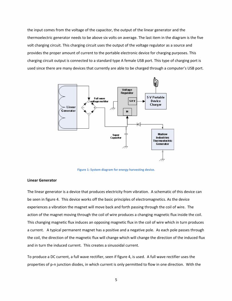
the input comes from the voltage of the capacitor, the output of the linear generator and the
thermoelectric generator needs to be above six volts on average. The last item in the diagram is the five
volt charging circuit. This charging circuit uses the output of the voltage regulator as a source and
provides the proper amount of current to the portable electronic device for charging purposes. This
charging circuit output is connected to a standard type A female USB port. This type of charging port is
used since there are many devices that currently are able to be charged through a computer’s USB port.
Figure 1: System diagram for energy harvesting device.
Linear Generator
The linear generator is a device that produces electricity from vibration. A schematic of this device can
be seen in figure 4. This device works off the basic principles of electromagnetics. As the device
experiences a vibration the magnet will move back and forth passing through the coil of wire. The
action of the magnet moving through the coil of wire produces a changing magnetic flux inside the coil.
This changing magnetic flux induces an opposing magnetic flux in the coil of wire which in turn produces
a current. A typical permanent magnet has a positive and a negative pole. As each pole passes through
the coil, the direction of the magnetic flux will change which will change the direction of the induced flux
and in turn the induced current. This creates a sinusoidal current.
To produce a DC current, a full wave rectifier, seen if figure 4, is used. A full wave rectifier uses the
properties of p‐n junction diodes, in which current is only permitted to flow in one direction. With the
5
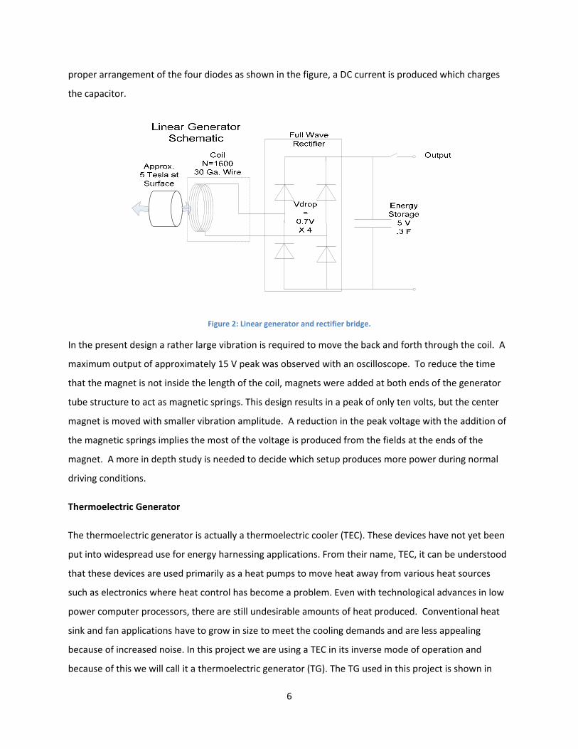
proper arrangement of the four diodes as shown in the figure, a DC current is produced which charges
the capacitor.
Figure 2: Linear generator and rectifier bridge.
In the present design a rather large vibration is required to move the back and forth through the coil. A
maximum output of approximately 15 V peak was observed with an oscilloscope. To reduce the time
that the magnet is not inside the length of the coil, magnets were added at both ends of the generator
tube structure to act as magnetic springs. This design results in a peak of only ten volts, but the center
magnet is moved with smaller vibration amplitude. A reduction in the peak voltage with the addition of
the magnetic springs implies the most of the voltage is produced from the fields at the ends of the
magnet. A more in depth study is needed to decide which setup produces more power during normal
driving conditions.
Thermoelectric Generator
The thermoelectric generator is actually a thermoelectric cooler (TEC). These devices have not yet been
put into widespread use for energy harnessing applications. From their name, TEC, it can be understood
that these devices are used primarily as a heat pumps to move heat away from various heat sources
such as electronics where heat control has become a problem. Even with technological advances in low
power computer processors, there are still undesirable amounts of heat produced. Conventional heat
sink and fan applications have to grow in size to meet the cooling demands and are less appealing
because of increased noise. In this project we are using a TEC in its inverse mode of operation and
because of this we will call it a thermoelectric generator (TG). The TG used in this project is shown in
6
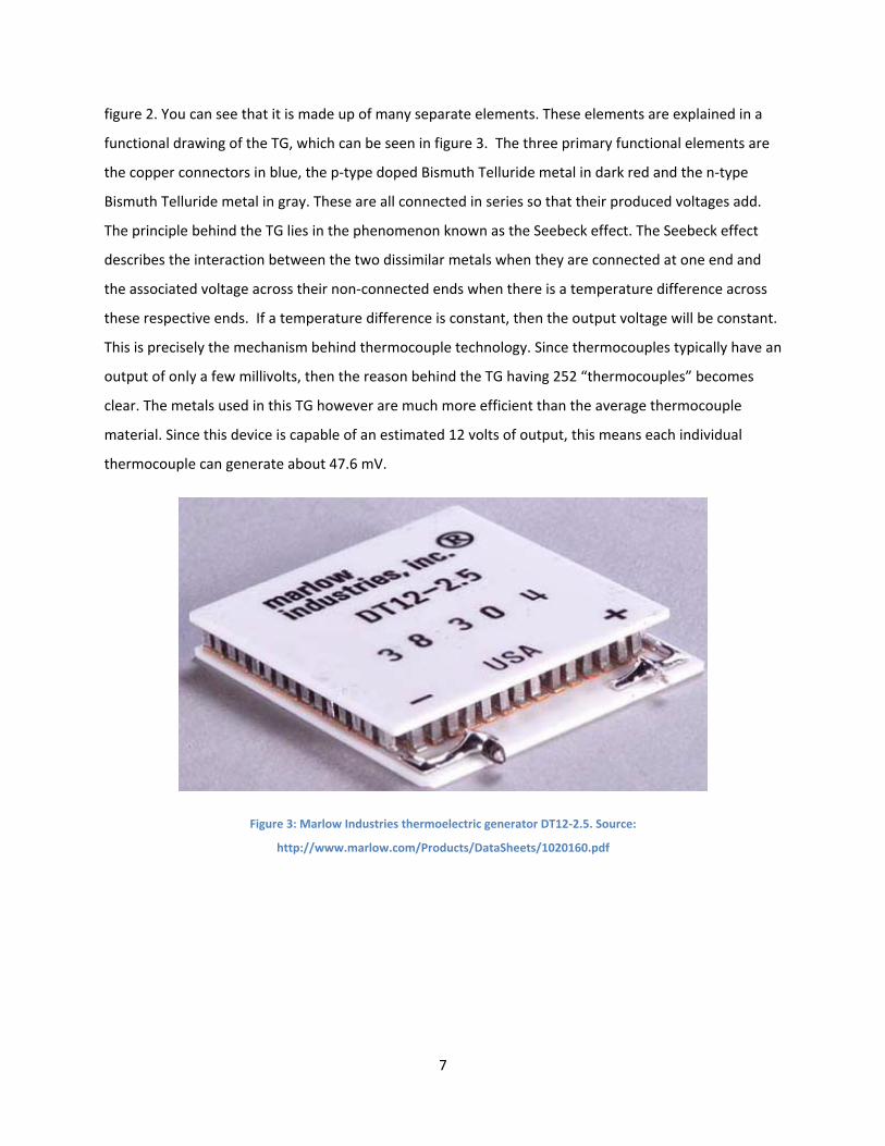
figure 2. You can see that it is made up of many separate elements. These elements are explained in a
functional drawing of the TG, which can be seen in figure 3. The three primary functional elements are
the copper connectors in blue, the p‐type doped Bismuth Telluride metal in dark red and the n‐type
Bismuth Telluride metal in gray. These are all connected in series so that their produced voltages add.
The principle behind the TG lies in the phenomenon known as the Seebeck effect. The Seebeck effect
describes the interaction between the two dissimilar metals when they are connected at one end and
the associated voltage across their non‐connected ends when there is a temperature difference across
these respective ends. If a temperature difference is constant, then the output voltage will be constant.
This is precisely the mechanism behind thermocouple technology. Since thermocouples typically have an
output of only a few millivolts, then the reason behind the TG having 252 “thermocouples” becomes
clear. The metals used in this TG however are much more efficient than the average thermocouple
material. Since this device is capable of an estimated 12 volts of output, this means each individual
thermocouple can generate about 47.6 mV.
Figure 3: Marlow Industries thermoelectric generator DT12‐2.5. Source:
http://www.marlow.com/Products/DataSheets/1020160.pdf
7
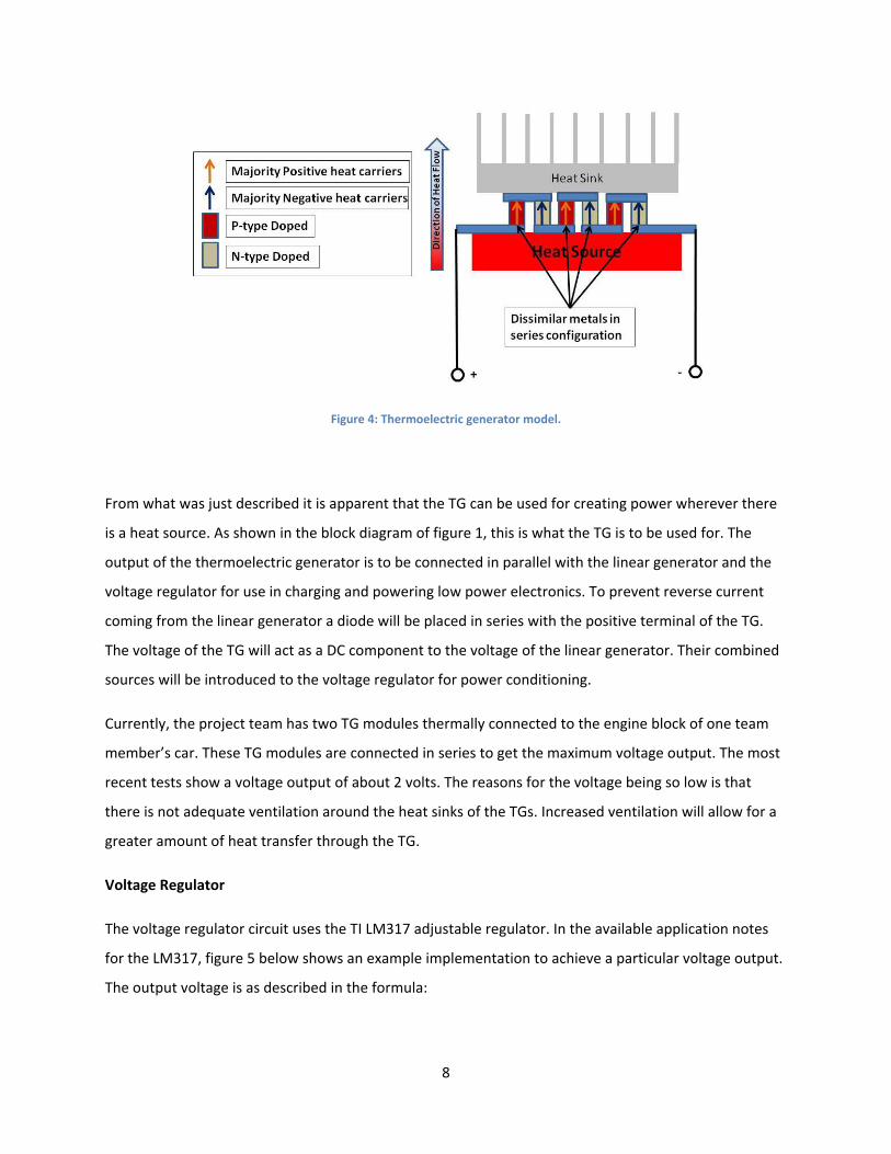
Figure 4: Thermoelectric generator model.
From what was just described it is apparent that the TG can be used for creating power wherever there
is a heat source. As shown in the block diagram of figure 1, this is what the TG is to be used for. The
output of the thermoelectric generator is to be connected in parallel with the linear generator and the
voltage regulator for use in charging and powering low power electronics. To prevent reverse current
coming from the linear generator a diode will be placed in series with the positive terminal of the TG.
The voltage of the TG will act as a DC component to the voltage of the linear generator. Their combined
sources will be introduced to the voltage regulator for power conditioning.
Currently, the project team has two TG modules thermally connected to the engine block of one team
member’s car. These TG modules are connected in series to get the maximum voltage output. The most
recent tests show a voltage output of about 2 volts. The reasons for the voltage being so low is that
there is not adequate ventilation around the heat sinks of the TGs. Increased ventilation will allow for a
greater amount of heat transfer through the TG.
Voltage Regulator
The voltage regulator circuit uses the TI LM317 adjustable regulator. In the available application notes
for the LM317, figure 5 below shows an example implementation to achieve a particular voltage output.
The output voltage is as described in the formula:
8
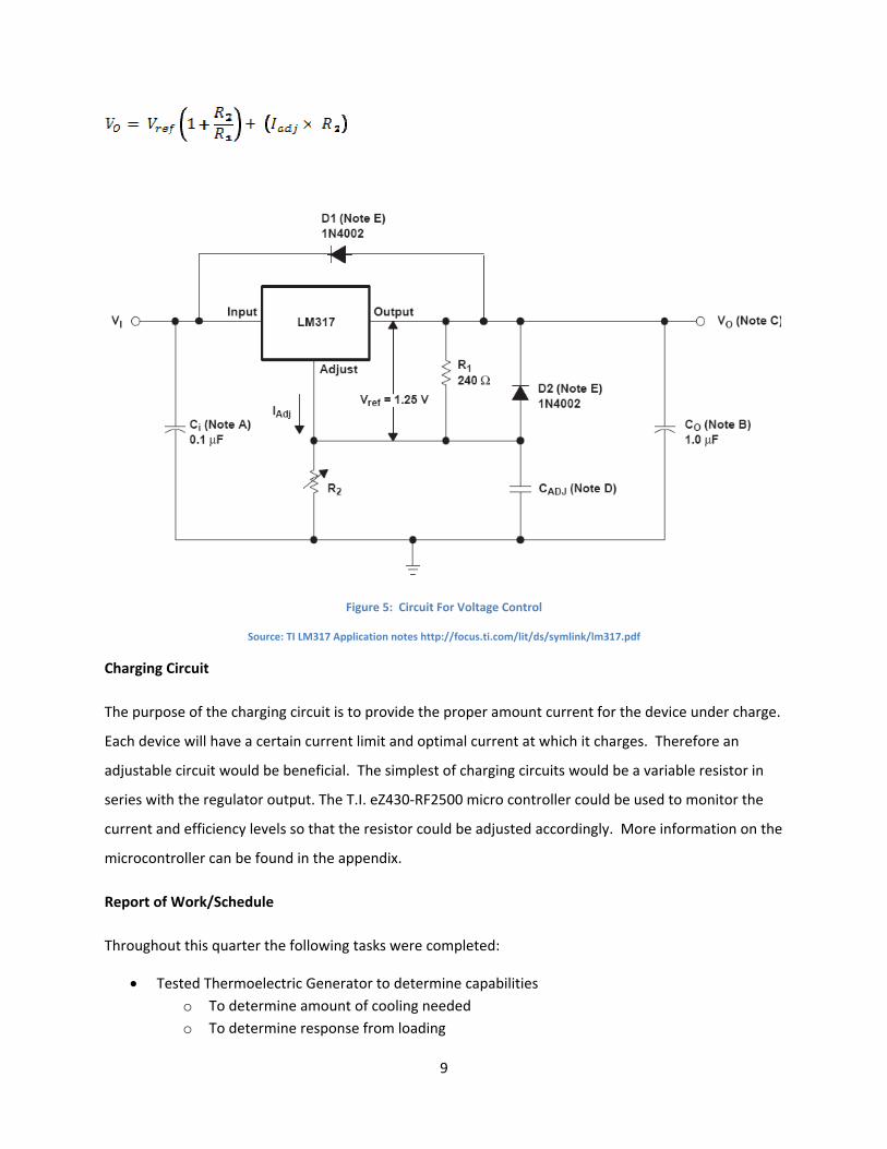
Figure 5: Circuit For Voltage Control
Source: TI LM317 Application notes http://focus.ti.com/lit/ds/symlink/lm317.pdf
Charging Circuit
The purpose of the charging circuit is to provide the proper amount current for the device under charge.
Each device will have a certain current limit and optimal current at which it charges. Therefore an
adjustable circuit would be beneficial. The simplest of charging circuits would be a variable resistor in
series with the regulator output. The T.I. eZ430‐RF2500 micro controller could be used to monitor the
current and efficiency levels so that the resistor could be adjusted accordingly. More information on the
microcontroller can be found in the appendix.
Report of Work/Schedule
Throughout this quarter the following tasks were completed:
• Tested Thermoelectric Generator to determine capabilities o To determine amount of cooling needed o To determine response from loading
9

• Installed Thermoelectric Generator on Car
• Analyzed Design of Linear Generator with Oscilloscope
• Began Programming and debugging microcontroller to monitor voltage levels
Personnel
Sungook Choi has extensive experience by design project of Low Noise Amplifier Design Project and
Analysis and Simulation of a Sequential Machine. In addition, he has laboratory experience with Noise
Figure Meter, Network Analyzer, AutoCAD Professional 8, VHDL, Xilinx ISE 10. He will be supervising the
circuit board design.
Derek Reese has focused primarily on electromagnetics and power with in the Electrical Engineering
department but has some experience with circuit and controls. He will be overseeing the selection and
programming of the microcontroller and plans to help with the power electronics. He will also be taking
an independent study winter quarter to further his knowledge in microcontrollers and or power
electronics.
Joel Mansfield has current research experience in the areas of electromagnetics and imaging techniques.
His educational focuses are in electromagnetics and power. He is capable of using many types of
electronic measurement equipment such as oscilloscopes, multi‐meters, network analyzers and
frequency generators. Additionally, he is knowledgeable in software programs like Agilent ADS and
MATLAB. He will be in charge of the task of system integration and thermoelectric generator installation
and tuning.
Thomas Caly is a senior electrical engineering student at the Ohio State University. Having
studied in France at the INSA de Lyon and completed an internship in the electromagnetic compatibility,
his main area of focus is in electromagnetics and more specifically antenna design, microwave (RF)
circuits, integrated optics, and data acquisition and processing in Synthetic Aperture Radar. He will be
supervising the design of the charging circuit/power electronics.
10

Design Review
At the beginning of this project it was the team’s goal to build a shock absorber using a linear generator.
This goal turned out to be a bit unrealistic given the allowed time for this project. A new plan was
devised to reduce the size of the linear generator and use this for applications on a smaller scale such as
supplying energy low power electronic devices used in the field by the military. This would provide
great benefit because it would reduce need to rely on battery power. The design of this linear generator
would be quiet simple but very reliable. Some changes were discussed about the design of this linear
generator. Due to the need for large vibrations to move the magnet through the coil, magnetic springs
were suggested. In fact, when these were added, it greatly reduced the force required to move the
magnet.
The team also brought about the idea to produce electricity from heat using a thermoelectric generator.
Given the specs on the generator, it was believed that this could be used to charge a battery of a car.
There were problems achieving this though due to cooling issues. The thermoelectric generator is now
going to be used to power small electronic devices.
The original design did not include a way to log the power output of the device, so some preliminary
work was done to achieve this with the TI MSP430 series microcontroller. The details of the work is
shown in the appendix.
11
Appendix
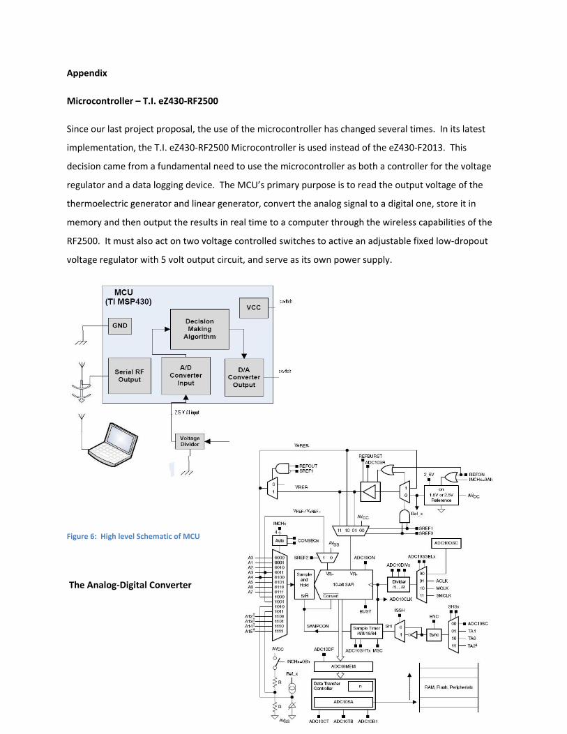
Microcontroller – T.I. eZ430‐RF2500
Since our last project proposal, the use of the microcontroller has changed several times. In its latest
implementation, the T.I. eZ430‐RF2500 Microcontroller is used instead of the eZ430‐F2013. This
decision came from a fundamental need to use the microcontroller as both a controller for the voltage
regulator and a data logging device. The MCU’s primary purpose is to read the output voltage of the
thermoelectric generator and linear generator, convert the analog signal to a digital one, store it in
memory and then output the results in real time to a computer through the wireless capabilities of the
RF2500. It must also act on two voltage controlled switches to active an adjustable fixed low‐dropout
voltage regulator with 5 volt output circuit, and serve as its own power supply.
Figure 6: High level Schematic of MCU
The Analog‐Digital Converter
12

The ADC module of the microcontroller supports fast, 10‐bit analog‐to‐digital conversions with an easy
to use data transfer controller (DTC). The ADC will be used to convert the analog voltage output of the
thermoelectric generator and linear generator into a digital output that can be stored in the RAM of the
MCU and then used for various functions.
The ADC10 module can be used through the programming of various controllers, namely ADC10CTL0,
ADC10CTL1, ADC10AE0, ADC10AE1, ADC10DTC0, ADC10DTC1, and
ADC10SA. For our configuration we decided on the
the block diagram in Figure 6:
F
• Internal voltage reference (SREFx) –
• ADC10 Sample and Hold time (ADC1
• Multiple sample and conversion on
• Reference‐generator voltage (REFO
• Interrupts (ADC10IE) ‐ Enabled
• Input Channel Select (INCHx) and An
• Sample and Hold Source (SHSx) – AD
• ADC10 Data Format (ISSH) – Straigh
• ADC10 Clock Source Select (ADC10S
• Conversion Sequence Mode (CONSE
• ADC10 One‐block transfer mode (AD
ADC10SC set
• 64 Transfers per block (ADC10DTC1
For information on individual bit setting for each co
User Guide.
The main two control registers being ADC10CTL0 an
1
igure 7: Detailed Schematic of MCU
following parameters, which can be referenced to
Vr+ = Vref+ and Vr‐ = Vss
0SHTx)– 64x ADC10CLKs
(MSC)‐ continous sample‐conversions
N) – set to 2.5V
alog Input Enable Register (ADC10AE0x) – A1
C10SC bit
t Binary
SELx) – MCLK
Qx) – Repeat Single‐channel
C10DTC0), Enable on ENC, start conversion on
) with start address of 0200h – 027Fh
ntroller, please refer to the TI MSP430F2xxx Family
d ADC10CTL1, they are set as follows:
3
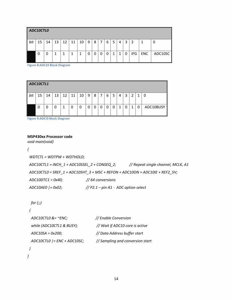
ADC10CTL0
bit 15 14 13 12 11 10 9 8 7 6 5 4 3 2 1 0
0 0 1 1 1 1 0 0 0 0 1 1 0 IFG ENC ADC10SC
Figure 8:ADC10 Block Diagram
ADC10CTL1
bit 15 14 13 12 11 10 9 8 7 6 5 4 3 2 1 0
0 0 0 1 0 0 0 0 0 0 0 1 0 1 0 ADC10BUSY
Figure 9:ADC!0 Block Diagram
MSP430xx Processor code void main(void)
{
WDTCTL = WDTPW + WDTHOLD;
ADC10CTL1 = INCH_1 + ADC10SSEL_2 + CONSEQ_2; // Repeat single channel, MCLK, A1
ADC10CTL0 = SREF_1 + ADC10SHT_3 + MSC + REFON + ADC10ON + ADC10IE + REF2_5V;
ADC10DTC1 = 0x40; // 64 conversions
ADC10AE0 |= 0x02; // P2.1 – pin A1 ‐ ADC option select
for (;;)
{
ADC10CTL0 &= ~ENC; // Enable Conversion
while (ADC10CTL1 & BUSY); // Wait if ADC10 core is active
ADC10SA = 0x200; // Data Address buffer start
ADC10CTL0 |= ENC + ADC10SC; // Sampling and conversion start
}
}
14