Embed Size (px)
Citation preview
BRUNSWICK COUNTY, NORTH CAROLINA
ENGINEERING DESIGN MANUAL
TECHNICAL SPECIFICATIONS
AND STANDARD DETAILS
FOR WATER AND SEWER SYSTEMS
June 2014
June 2014 Brunswick County Engineering Department Revision 1.3
ENGINEERING DESIGN MANUAL, TECHNICAL SPECIFICATIONS, AND STANDARD DETAILS
TABLE OF CONTENTS
A. INTRODUCTION B. SECTION 1: DESIGN GUIDANCE MANUAL
• Administrative Information
• Plan Review and Approval Process
• Construction Process
• Substantial Completion Process
• Final Acceptance Process
• Legal Documents Requirements
A) Easements B) Plats C) Deed of Dedication D) Lien Waiver Affidavit E) Water and Sewer Indemnity Agreements
• Water, Sewer, and Pump Station Design Information
A) Water Systems B) Gravity Sewer Systems C) Sewer Force Main Systems D) Sewage Pumping Station Systems E) Sand, Oil, and Grease Interceptor Systems F) Low Pressure Sewer Systems with Grinder Pumps G) Vacuum Sewer Systems
• Other Design Information A) Cross Connection and Backflow Protection Policy B) Wastewater Pumping Station Design Guidelines C) Brunswick County Rural Sewer Policy D) Drawing Submittals Required for a Sewer Pump Station in Brunswick County
2
June 2014 Brunswick County Engineering Department Revision 1.3
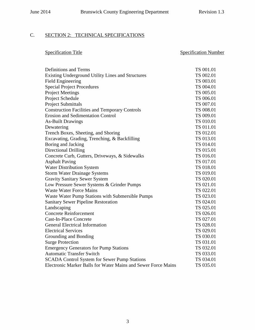
C. SECTION 2: TECHNICAL SPECIFICATIONS Specification Title Specification Number Definitions and Terms TS 001.01 Existing Underground Utility Lines and Structures TS 002.01 Field Engineering TS 003.01 Special Project Procedures TS 004.01 Project Meetings TS 005.01 Project Schedule TS 006.01 Project Submittals TS 007.01 Construction Facilities and Temporary Controls TS 008.01 Erosion and Sedimentation Control TS 009.01 As-Built Drawings TS 010.01 Dewatering TS 011.01 Trench Boxes, Sheeting, and Shoring TS 012.01 Excavating, Grading, Trenching, & Backfilling TS 013.01 Boring and Jacking TS 014.01 Directional Drilling TS 015.01 Concrete Curb, Gutters, Driveways, & Sidewalks TS 016.01 Asphalt Paving TS 017.01 Water Distribution System TS 018.01 Storm Water Drainage Systems TS 019.01 Gravity Sanitary Sewer System TS 020.01 Low Pressure Sewer Systems & Grinder Pumps TS 021.01 Waste Water Force Mains TS 022.01 Waste Water Pump Stations with Submersible Pumps TS 023.01 Sanitary Sewer Pipeline Restoration TS 024.01 Landscaping TS 025.01 Concrete Reinforcement TS 026.01 Cast-In-Place Concrete TS 027.01 General Electrical Information TS 028.01 Electrical Services TS 029.01 Grounding and Bonding TS 030.01 Surge Protection TS 031.01 Emergency Generators for Pump Stations TS 032.01 Automatic Transfer Switch TS 033.01 SCADA Control System for Sewer Pump Stations TS 034.01 Electronic Marker Balls for Water Mains and Sewer Force Mains TS 035.01
3
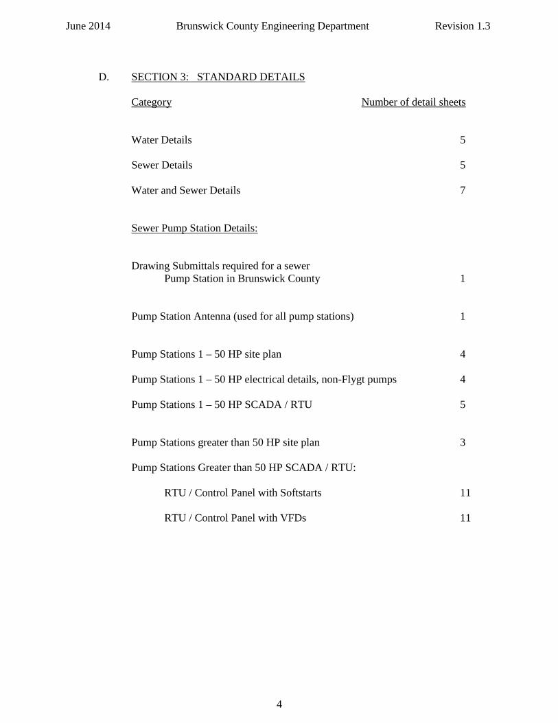
June 2014 Brunswick County Engineering Department Revision 1.3 D. SECTION 3: STANDARD DETAILS Category Number of detail sheets
Water Details 5
Sewer Details 5 Water and Sewer Details 7 Sewer Pump Station Details:
Drawing Submittals required for a sewer Pump Station in Brunswick County 1 Pump Station Antenna (used for all pump stations) 1
Pump Stations 1 – 50 HP site plan 4 Pump Stations 1 – 50 HP electrical details, non-Flygt pumps 4
Pump Stations 1 – 50 HP SCADA / RTU 5 Pump Stations greater than 50 HP site plan 3 Pump Stations Greater than 50 HP SCADA / RTU:
RTU / Control Panel with Softstarts 11 RTU / Control Panel with VFDs 11
4
June 2014 Brunswick County Engineering Department Revision 1.3
INTRODUCTION
Any proposed additions to the water distribution and sanitary sewer collection systems of Brunswick County must meet minimum design standards to conform to State rules and the requirements of the Brunswick County Engineering and Public Utilities departments. The County requirements are contained in this “Engineering Design Manual, Technical Specifications, and Standard Details for Water and Sewer Systems” manual, hereinafter referred to as the “County Design Manual”, or the “Design Manual”. This design manual is divided into three sections. These are:
• A general Design Section to assist with understanding design requirements, legal requirements, and plan review and approval procedures,
• Technical Specifications for the use of the design and contracting community, and
• Standard Details for water and sewer infrastructure to be included in all plan submittals.
Adherence to State and County regulations and this Design Manual will ensure a quality water and sewer system for the citizens of Brunswick County, and will also facilitate an increased system life span as well as a reduction in overall cost of operations and maintenance. These guidelines have been adopted by the Brunswick County Commissioners, and shall be incorporated into the design and construction of all water distribution and sanitary sewer systems. Brunswick County realizes that there are occasions when extenuating circumstances occur and, therefore, these guidelines sometimes will not be the best choice for certain situations. In these cases please consult with County Engineering to obtain approval for any alternative designs. Meetings may be requested with County Engineering at:
Brunswick County Engineering Department Building G 20 Referendum Drive, NE Bolivia, NC 28422
(910) 253-2500 [email protected] Copies of this Design Manual can be obtained from the Brunswick County web page or County Engineering.
This design manual is subject to updates on a periodic basis. Revisions will be posted on the Brunswick County web page or may be obtained from County Engineering. Pages are dated and numbered to assist in the maintenance of current information. It is the responsibility of the public to ensure they have the most recently approved version of the Design Manual for their use.
5
June 2014 Brunswick County Engineering Department Revision 1.3 Any questions or comments concerning this Design Manual should be submitted to the Brunswick County Engineering Department at 910.253.2500 or [email protected]. Brunswick County will only consider for ownership, operation, and maintenance water and sanitary sewer systems installed:
1) Within the boundaries of Brunswick County and in the service area of the County Public Utilities Department,
2) In accordance with this Design Manual,
3) In accordance with Brunswick County’s most recent Water and Wastewater
Master Plans. Developers and their design engineers are encouraged to contact Brunswick County, prior to beginning design, to ensure their project is consistent with Brunswick County Public Utilities’ master planning for water and sewer systems,
4) In accordance with the latest version of the Brunswick County Sewer Use
Ordinance and Utility Policy, 5) In accordance with all minimum design criteria for water and sewer systems as
published by the North Carolina Department of Environmental and Natural Resources, Divisions of Water Quality and Public Water Supply,
6) In accordance with plans and specifications approved by Brunswick County and
complying with the procedures outlined in this Design Manual, 7) In accordance with the provisions of a detailed agreement approved by the Board
of Commissioners if either or both of these systems require the installation of water supply facilities or wastewater treatment disposal facilities,
8) In accordance with the provisions of any water and/or sewer transmission
reimbursement agreements approved by the Board of Commissioners.
6
June 2014 Brunswick County Engineering Department Revision 1.3
SECTION 1
DESIGN GUIDANCE MANUAL
BRUNSWICK COUNTY ENGINEERING DEPARTMENT
7
June 2014 Brunswick County Engineering Department Revision 1.3
ADMINISTRATIVE INFORMATION The following is a general description of the responsibilities of the parties involved with the design, review and approval of water and sewer installation projects in Brunswick County: 1) Brunswick County Engineering Department
a) County Engineering will review plans submitted by a licensed professional engineer in the State of North Carolina and grant approval after all review comments have been satisfactory addressed.
b) The County reserves the right to request changes in the work that is not in
accordance with this Design Manual, or if work is being performed in an improper manner that may result in incorrect installation of the water and/or the sanitary sewer system.
c) The County reserves the right to disallow work from an Engineer or Developer
who consistently does not comply with this Design Manual and other County policies.
d) The County reserves the right to request revisions to the Design Engineer’s plans
for any discrepancies found during construction that may have been overlooked during review of the plans and specifications.
e) Pre-Construction Conferences are required with County Engineering prior to any
work on County owned utility systems. 2) Design Engineer of Record
a) The Design Engineer of Record is a North Carolina state licensed professional engineer hired by a developer or property owner to prepare a set of plans and specifications for submittal to County Engineering for review and approval.
b) The Design Engineer will:
1) Prepare plans and specifications in accordance with this Design Manual, all North Carolina Department of Environment and Natural Resources (NCDENR) regulations, and all other local, state and federal regulations pertaining to the project. 2) Ensure plans are consistent with Brunswick County’s water and sewer master plans.
3) Submit plans and specifications to County Engineering for review and
approval. 4) Make any revisions necessary to the plans and specifications to comply
with any and all plan review comments received from Brunswick County Engineering Department staff.
8
June 2014 Brunswick County Engineering Department Revision 1.3 5) Submit for all required permits with State agencies on behalf of their
clients after plan approval is received from County Engineering. 6) Attend the mandatory Pre-Construction Conference once all permits are
issued and the conference is scheduled as requested.
7) Review all phases of the work in progress during construction and conduct any required testing of systems in order to be able to issue “Engineering Certification” for the project.
8) Promptly furnish Brunswick County with pertinent information
concerning any changes which may be necessary during the progress of the work. No major changes shall be performed without the prior approval of Brunswick County.
9) Obtain final approval from Brunswick County and applicable state and
federal agencies. 10) Provide sealed record drawings (asbuilts) in paper, PDF, and AutoCAD
format at the conclusion of the project per County requirements. Currently the AutoCAD format for submitted record drawings must be AutoCAD 2007 or later version. Individual PDFs of each plan sheet must also be provided as part of the asbuilt record drawing submittal.
9
June 2014 Brunswick County Engineering Department Revision 1.3
PLAN REVIEW AND APPROVAL PROCESS
The following is a general description of the plan submittal, review, and approval process for proposed extensions of the Brunswick County water distribution and sanitary sewer collection systems: 1) General Information a) For new water and/or sewer main extensions a complete plan submittal shall
consist of the following items: (1) set of plans including County standard details, County technical specifications, engineering calculations, related modeling information for water, sewer, and fire flow as applicable, water and / or sewer main extension permit applications, Engineer’s Report, and engineering narrative. All submittals must be sealed by a North Carolina state licensed professional engineer.
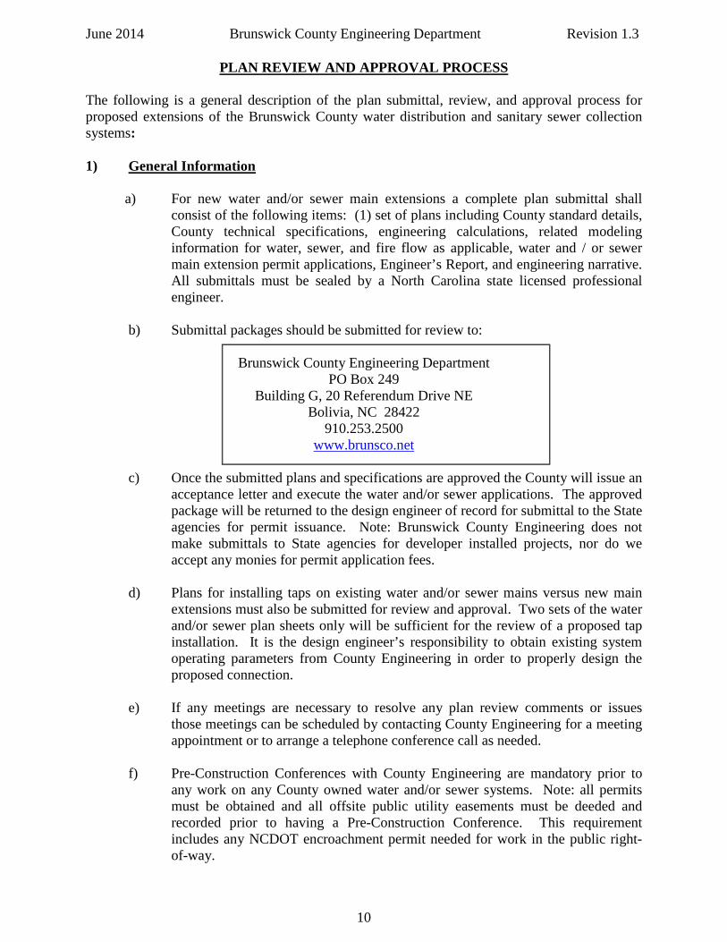
b) Submittal packages should be submitted for review to:
Brunswick County Engineering Department PO Box 249
Building G, 20 Referendum Drive NE Bolivia, NC 28422
910.253.2500 www.brunsco.net
c) Once the submitted plans and specifications are approved the County will issue an
acceptance letter and execute the water and/or sewer applications. The approved package will be returned to the design engineer of record for submittal to the State agencies for permit issuance. Note: Brunswick County Engineering does not make submittals to State agencies for developer installed projects, nor do we accept any monies for permit application fees.
d) Plans for installing taps on existing water and/or sewer mains versus new main
extensions must also be submitted for review and approval. Two sets of the water and/or sewer plan sheets only will be sufficient for the review of a proposed tap installation. It is the design engineer’s responsibility to obtain existing system operating parameters from County Engineering in order to properly design the proposed connection.
e) If any meetings are necessary to resolve any plan review comments or issues
those meetings can be scheduled by contacting County Engineering for a meeting appointment or to arrange a telephone conference call as needed.
f) Pre-Construction Conferences with County Engineering are mandatory prior to
any work on any County owned water and/or sewer systems. Note: all permits must be obtained and all offsite public utility easements must be deeded and recorded prior to having a Pre-Construction Conference. This requirement includes any NCDOT encroachment permit needed for work in the public right-of-way.
10
June 2014 Brunswick County Engineering Department Revision 1.3
2) Preliminary Plan Approval
a) Developers, Designers, Planners, Engineers and others associated with submitting design proposals should ensure that the proposed project conforms to the most recent edition of the County’s water and sewer master plans.
b) Plans that only require installing new taps to existing water and/or sewer mains
versus new main extensions will be reviewed on an expedited basis.
c) For water and/or sewer main extensions the Design Engineer shall submit a preliminary review package to Brunswick County. The package shall include the following at a minimum:
1) One set of water and / or wastewater utility plans. Plans should include:
a) Cover sheet showing general location of project utilizing the Brunswick County Standard Title Sheet. The Standard Title Sheet is available on the County website on the Engineering Department webpage
b) Complete water and / or sewer systems design, including plan and profile for proposed gravity sewer systems, and associated County Standard Details
c) Location and width of all existing public and private access and utility easements d) Location and width of all proposed private access and utility easements
e) Location and width of all proposed public access and utility easements to be dedicated to Brunswick County
f) Location and width of all proposed temporary construction
easements
g) Indicate all rights-of-way as either public or private. Plans should also indicate ownership of existing roadways h) For all commercial developments show location of all proposed water and sewer service taps and size of water meter i) County Tax Map Parcel ID number for the project property
2) One set of typed calculations sealed by the Engineer. 3) Engineer’s Report for water main extension requests. 4) Any required water and / or sewer modeling information.
11
June 2014 Brunswick County Engineering Department Revision 1.3 d) Upon review and approval County Engineering will return to the Design
Engineer:
1) Written review comments on the proposed design. 2) Written approval if no changes are required. 3) Notification of any required encroachment applications, certifications,
permits, or easements. 4) Request for any other required information pertinent to the proposed
project. 3) Final Plan Approval
a) Once preliminary plan approval is received, the design Engineer shall submit the following to County Engineering:
1) One complete set of plans addressing all corrections requested by County
Engineering. The final submittal will be checked against the set of plans and specifications retained by County Engineering during “Preliminary Plan Approval” for completeness and accuracy.
2) Completed permit applications to be signed by the County management
authority. These include water, sewer, pump station, NCDOT encroachment, etc., permit applications. Note: it is the responsibility of the design engineer of record to submit the permit applications to the appropriate State agencies for permitting along with any required permit applications fees after permit application execution by the County.
3) Letter from the County (or Municipality) Fire Marshall indicating
approval of fire hydrant locations, FDC placement on buildings, proximity of a fire hydrant to any proposed FDC, etc.
b) County Engineering will prepare for pickup by the Engineer:
1) One set of plans and specifications marked “Approved for Construction”. 2) Executed water, sewer, and/or NCDOT encroachment permit applications
for the applicant to use for submittal to State agencies for permitting. 3) The “Plans & Specifications Approval Letter” for use in submitting permit
applications to the DENR / PWSS / DWQ.
12
June 2014 Brunswick County Engineering Department Revision 1.3
CONSTRUCTION PROCESS
The following is a general description of the construction process for proposed extensions of the Brunswick County water distribution and sanitary sewer collection systems: 1) General Information
a) The following items (as applicable) must be received by Brunswick County Engineering prior to scheduling a Pre-Construction Conference (“PreCon”) and receiving permission to work on utility systems owned by Brunswick County:
• DENR / PWSS water main extension permit • DENR / DWQ sewer main extension permit • DENR/DWQ sewer pump station permit • DENR/DWQ low pressure sewer main extension permit • NCDOT Right of Way Encroachment • Deed of Easement recorded for any required offsite public utility
easements • Shop Drawings - Brunswick County may require the submittal of Shop
Drawings for pumps, valves, hydrants, and other appurtenances involving construction of water and sewer systems. Notification will be made in writing to the Developer’s design engineer if shop drawings are deemed necessary by County Engineering for review and approval
• Stormwater Permits – State and County – if required to begin any site grading preparatory to installation of water and/or sewer infrastructure
b) Construction should be coordinated in advance with County Engineering – a
minimum of forty-eight (48) hours notice is required for scheduling purposes for the pre-construction meeting.
c) PreCons are held at County Engineering in the conference room at the specified
time scheduled by the Engineering Department. At the discretion of the County Engineer and the Engineering Inspector assigned to the construction project a field PreCon may be allowed. All field PreCons will be scheduled by the Engineering Inspector assigned to the project.
d) The design engineer and North Carolina licensed utility contractor must attend the
PreCon – if any utility work is to be sub-contracted to a second firm that firm must also be a North Carolina licensed utility contractor and must attend the PreCon. The utility contractor foreman, supervisor, or project manager who will oversee daily work activities in the field must be present at the PreCon.
e) NCDOT requires a separate PreCon before beginning any work in the public
rights-of-way – this PreCon must be scheduled by the Developer or the Design Engineer for developer installed infrastructure. The County Engineering Inspector will attend the NCDOT PreCon as the County representative. All requirements in the issued NCDOT Encroachment Permit must be fulfilled by the contractor preparatory to beginning work on the project.
13
June 2014 Brunswick County Engineering Department Revision 1.3 2) Construction Activity a) After the completion of all required pre-construction meetings the contractor may
commence construction on the project with a forty-eight (48) hour notice to the County Engineering Inspector.
b) Once construction commences the primary contact person for the project will be
the County Engineering Inspector assigned to the project. c) All water, sewer, and pump station infrastructure will be installed in accordance
with this Design Manual, and in accordance with the requirements in all State issued permits for the project.
d) All required system testing will be conducted in accordance with this Design
Manual, and under the direction of the County Engineering Inspector. e) If any requirements for carrying out construction are not met, Brunswick County
reserves the right to issue a Stop Work Order for the project. f) If a Stop Work Order is issued for a project, a second PreCon will be required
before work can commence again to discuss the issues and required corrective actions. This PreCon will be held in the offices of County Engineering to discuss the relevant issues and requirements for work to be allowed to commence again.
g) At the completion of construction and prior to start up the developer, design
engineer, or contractor must provide (3) copies minimum, or as specified in the relevant Technical Specification for a particular system or piece of equipment, all operational, maintenance, and service manuals (O & M Manuals) as needed for any pump station equipment or other specialty type equipment specific to the project.
h) The project will be deemed Substantially Complete once all the requirements in
the SUBSTANTIAL COMPLETION section of this Design Manual have been met and approved by County Engineering staff.
i) There is a mandatory one year warranty that must be provided by the Developer
for all developer installed water, sewer, and pump station infrastructure. This warranty begins on the date of recordation of the Deed of Dedication and Affidavit by the Brunswick County Legal Department after review and acceptance by the Brunswick County Board of Commissioners at a regularly scheduled Board meeting.
14
June 2014 Brunswick County Engineering Department Revision 1.3
SUBSTANTIAL COMPLETION PROCESS
The following is a general description of the process for proposed extensions of the Brunswick County water distribution and sanitary sewer collection systems to be deemed “Substantially Complete”:
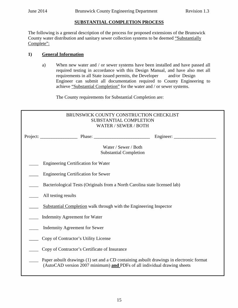
1) General Information a) When new water and / or sewer systems have been installed and have passed all
required testing in accordance with this Design Manual, and have also met all requirements in all State issued permits, the Developer and/or Design Engineer can submit all documentation required to County Engineering to achieve “Substantial Completion” for the water and / or sewer systems.
The County requirements for Substantial Completion are:
BRUNSWICK COUNTY CONSTRUCTION CHECKLIST SUBSTANTIAL COMPLETION
WATER / SEWER / BOTH
Project: ________________ Phase: ________________________ Engineer: __________________
Water / Sewer / Both Substantial Completion
____ Engineering Certification for Water ____ Engineering Certification for Sewer ____ Bacteriological Tests (Originals from a North Carolina state licensed lab) ____ All testing results ____ Substantial Completion walk through with the Engineering Inspector ____ Indemnity Agreement for Water ____ Indemnity Agreement for Sewer ____ Copy of Contractor’s Utility License ____ Copy of Contractor’s Certificate of Insurance ____ Paper asbuilt drawings (1) set and a CD containing asbuilt drawings in electronic format (AutoCAD version 2007 minimum) and PDFs of all individual drawing sheets
15
June 2014 Brunswick County Engineering Department Revision 1.3 b) The Construction Checklist for Substantial Completion is available on the County website at www.brunsco.net or may be obtained from County Engineering. c) The Water Indemnity Agreement and the Sewer Indemnity Agreement are
available on the County website at www.brunsco.net or may be obtained from County Engineering.
d) Once newly installed water and sewer systems have achieved Substantial Completion a letter will be sent to the design engineer, and Brunswick County will allow a water meter to be installed and water service to commence. NOTE: a Certificate of Occupancy (C.O) will not be issued until Final Acceptance (Deed of Dedication) has occurred. e) The requirements for asbuilt (record) drawings are covered in detail in Technical
Specification 010.01: As-Built Drawings. 1) Basic information required for asbuilts:
Cover sheet with subdivision or project name, date, scale, and north arrow. Sealed by a North Carolina licensed Professional Land Surveyor or Professional Engineer (engineer seal required for all profiles).
For sewer projects, the asbuilt plans shall include accurate information regarding pipe size, pipe material, pipe length, manhole construction (size of manhole, invert, rim, alignment, and location), services, and pump stations along with any relevant rights-of-way, utility easements, and property boundaries.
For pump stations, the asbuilt plans shall include accurate information regarding interior and exterior pipe sizes, material, and length, as well as all structural dimensions of the pump station, all electrical equipment (make and model), pump information (make, model, and impeller size), and site layout information. Both top view and side view drawings are required on the asbuilt plans.
For water projects, the asbuilt plans shall include accurate information regarding pipe size, pipe material, pipe length, valve locations, hydrant locations, fitting locations, services, and blow off locations along with any relevant rights-of-way, utility easements, and property boundaries.
Refer to Technical Specification 010.01: As-Built Drawings for complete asbuilt record drawings requirements.
f) Contact Brunswick County Engineering Department concerning any guidance needed with the Substantial Completion Process.
16
June 2014 Brunswick County Engineering Department Revision 1.3
FINAL ACCEPTANCE OF INSTALLED INFRASTRUCTURE PROCESS
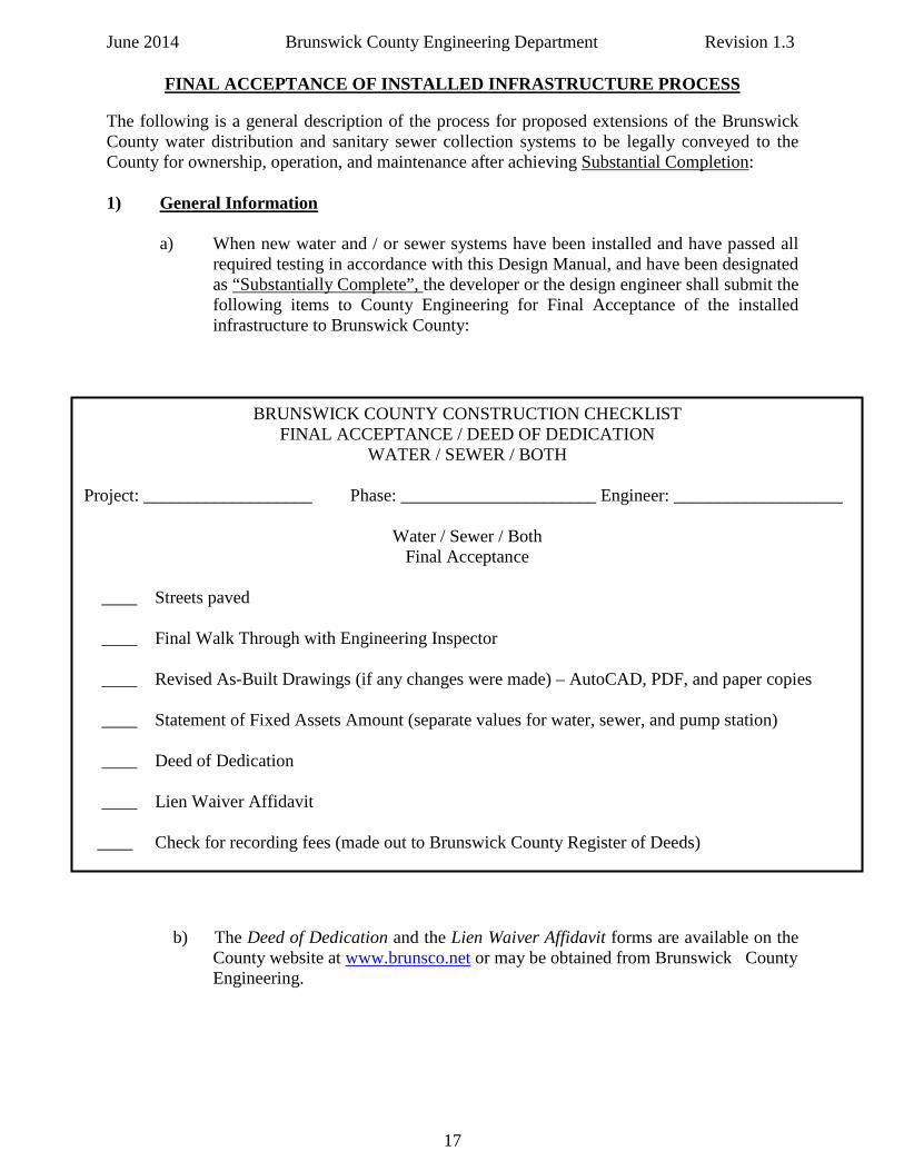
The following is a general description of the process for proposed extensions of the Brunswick County water distribution and sanitary sewer collection systems to be legally conveyed to the County for ownership, operation, and maintenance after achieving Substantial Completion:
1) General Information a) When new water and / or sewer systems have been installed and have passed all
required testing in accordance with this Design Manual, and have been designated as “Substantially Complete”, the developer or the design engineer shall submit the following items to County Engineering for Final Acceptance of the installed infrastructure to Brunswick County:
b) The Deed of Dedication and the Lien Waiver Affidavit forms are available on the
County website at www.brunsco.net or may be obtained from Brunswick County Engineering.
BRUNSWICK COUNTY CONSTRUCTION CHECKLIST FINAL ACCEPTANCE / DEED OF DEDICATION
WATER / SEWER / BOTH
Project: ___________________ Phase: ______________________ Engineer: ___________________
Water / Sewer / Both Final Acceptance
____ Streets paved ____ Final Walk Through with Engineering Inspector ____ Revised As-Built Drawings (if any changes were made) – AutoCAD, PDF, and paper copies ____ Statement of Fixed Assets Amount (separate values for water, sewer, and pump station) ____ Deed of Dedication ____ Lien Waiver Affidavit ____ Check for recording fees (made out to Brunswick County Register of Deeds)
17
June 2014 Brunswick County Engineering Department Revision 1.3 c) Once all required items have been received and approved by County Engineering
the dedication package will be forwarded to the County Attorney for review and placement on the Board of Commissioner’s agenda for final acceptance.
d) The County Attorney will record the Deed of Dedication and Affidavit after
acceptance by the Board of Commissioners. The required one year warranty period for developer installed infrastructure will commence on the date of recording of the Deed of Dedication and Affidavit.
e) Contact Brunswick County Engineering Department concerning any guidance
needed with the Final Acceptance process.
18
June 2014 Brunswick County Engineering Department Revision 1.3
Legal Document Requirements
The following information is provided as a general guide concerning permanent easements, pump station sites, temporary construction easements, plat maps, and the Deed of Dedication. 1) Public Utility Easements
a) Public Utility Easements (PUE) shall be conveyed to Brunswick County in a standard format that is acceptable to County Engineering and County Legal. b) All required public utility easements needed for a project shall be deeded and recorded at the Brunswick County Registry of Deeds prior to requesting a Pre- Construction Conference to install any water and sewer infrastructure. c) All required offsite public utility easements required for a Plat Map shall be deeded and recorded either a) with the requested Plat Map or, b) as a separate Deed of Easement prior to the requested Plat Map being signed by County Engineering. d) All onsite public utility easements can be deeded at the time of dedication of any publically permitted infrastructure including utility easements for pump station sites. e) A developer must grant a public utility easement over all private streets within a subdivision if any public infrastructure is installed within the private street rights- of-way. This public easement may be granted with the Deed of Dedication for the infrastructure being legally conveyed to Brunswick County.
f) Water and sewer mains shall be installed outside of street pavement whenever possible. g) All water and sewer mains within a public utility easement shall be installed per County standards and must meet DENR/PWSS/DWQ requirements for separation between water and sewer mains. h) Structures are not permitted within public utility easements. i) Clear all easements of trees and debris. The easement is to be grassed unless other
treatment is specifically approved by Brunswick County. j) Any proposed facility to be constructed within a public utility easement or any crossing of a public utility easement will require permission of County
Engineering and / or Public Utilities prior to commencement of construction. k) All references to easements herein shall refer to permanent public utility
easements. Temporary construction easements shall be exclusive of the descriptions herein.
l) No trees or shrubs shall be planted in public utility easements.
19
June 2014 Brunswick County Engineering Department Revision 1.3
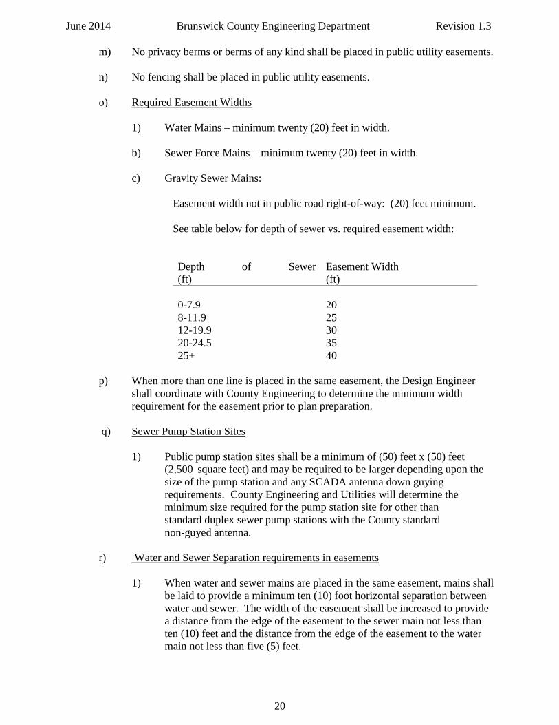
m) No privacy berms or berms of any kind shall be placed in public utility easements. n) No fencing shall be placed in public utility easements. o) Required Easement Widths
1) Water Mains – minimum twenty (20) feet in width. b) Sewer Force Mains – minimum twenty (20) feet in width. c) Gravity Sewer Mains:
Easement width not in public road right-of-way: (20) feet minimum. See table below for depth of sewer vs. required easement width: Depth of Sewer (ft)
Easement Width (ft)
0-7.9
20
8-11.9 25 12-19.9 30 20-24.5 35 25+ 40
p) When more than one line is placed in the same easement, the Design Engineer shall coordinate with County Engineering to determine the minimum width requirement for the easement prior to plan preparation. q) Sewer Pump Station Sites 1) Public pump station sites shall be a minimum of (50) feet x (50) feet (2,500 square feet) and may be required to be larger depending upon the size of the pump station and any SCADA antenna down guying requirements. County Engineering and Utilities will determine the minimum size required for the pump station site for other than standard duplex sewer pump stations with the County standard non-guyed antenna. r) Water and Sewer Separation requirements in easements 1) When water and sewer mains are placed in the same easement, mains shall be laid to provide a minimum ten (10) foot horizontal separation between water and sewer. The width of the easement shall be increased to provide a distance from the edge of the easement to the sewer main not less than ten (10) feet and the distance from the edge of the easement to the water main not less than five (5) feet.
20
June 2014 Brunswick County Engineering Department Revision 1.3
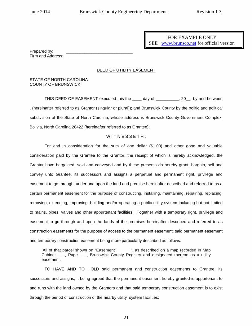
Prepared by: _____________________________ Firm and Address: _____________________________
DEED OF UTILITY EASEMENT
STATE OF NORTH CAROLINA COUNTY OF BRUNSWICK THIS DEED OF EASEMENT executed this the ____ day of __________, 20__, by and between
, (hereinafter referred to as Grantor (singular or plural)); and Brunswick County by the politic and political
subdivision of the State of North Carolina, whose address is Brunswick County Government Complex,
Bolivia, North Carolina 28422 (hereinafter referred to as Grantee);
W I T N E S S E T H :
For and in consideration for the sum of one dollar ($1.00) and other good and valuable
consideration paid by the Grantee to the Grantor, the receipt of which is hereby acknowledged, the
Grantor have bargained, sold and conveyed and by these presents do hereby grant, bargain, sell and
convey unto Grantee, its successors and assigns a perpetual and permanent right, privilege and
easement to go through, under and upon the land and premise hereinafter described and referred to as a
certain permanent easement for the purpose of constructing, installing, maintaining, repairing, replacing,
removing, extending, improving, building and/or operating a public utility system including but not limited
to mains, pipes, valves and other appurtenant facilities. Together with a temporary right, privilege and
easement to go through and upon the lands of the premises hereinafter described and referred to as
construction easements for the purpose of access to the permanent easement; said permanent easement
and temporary construction easement being more particularly described as follows:
All of that parcel shown on “Easement_______”, as described on a map recorded in Map Cabinet____, Page ___, Brunswick County Registry and designated thereon as a utility easement.
TO HAVE AND TO HOLD said permanent and construction easements to Grantee, its
successors and assigns, it being agreed that the permanent easement hereby granted is appurtenant to
and runs with the land owned by the Grantors and that said temporary construction easement is to exist
through the period of construction of the nearby utility system facilities;
FOR EXAMPLE ONLY SEE www.brunsco.net for official version
21
June 2014 Brunswick County Engineering Department Revision 1.3 The facilities to be placed under and upon and across the said permanent easement shall remain
the property of the Grantee. The Grantee shall have the right to inspect, remove, repair, replace,
maintain and improve the facility together with the rights of ingress and egress to the facilities, and to
make such changes and additions to the facilities upon the permanent easement as the Grantee from
time to time may deem advisable.
Except as otherwise stated herein, Grantee shall at all times have the right to keep the areas of
permanent easement clear of all buildings or structures and such vegetation as will, in its judgment,
interfere with the purpose of this easement. Except as otherwise stated herein, the Grantors expressly
promise and agree not to construct or allow to be constructed any building, structure or other
improvement and further, promises not to plant or allow to be planted any trees, shrubs, bushes,
undergrowth or other vegetation which Grantee may determine in its sole discretion would permit
encroachment or interference with Grantee’s rights hereunder. It is expressly understood and agreed
hereunder that the Grantors and their successors and assigns shall retain the right to cultivate the ground
lying within the boundaries of the permanent easement and use said easement for any other lawful
purpose, however, such cultivation or use shall not be inconsistent with the rights herein granted to the
Grantee, and Grantee, unless otherwise stated herein, shall not be liable to any damages or loss due to
the exercise of its rights hereunder within this easement.
Upon termination of the nearby construction work and its formal acceptance by the Grantee, the
Grantee then automatically relinquishes the temporary construction easement and all rights there
acquired.
By acceptance of this deed of easement, the Grantee agrees that it will restore the surface of the
land to its approximate level prior to the construction by filling or grading in the course of construction or
maintenance of the aforesaid facilities so long as the same are not inconsistent with or do not interfere
with the rights herein granted to the Grantee. It is specifically agreed that any trees removed for the
construction or maintenance work will not be replaced.
The construction or maintenance area may be seeded by the Grantee, but the Grantee will not be
responsible for landscaping or otherwise improving the area. It is understood and agreed that the
execution and clearing of this deed by the Grantors and its acceptance by the Grantee shall not obligate
the Grantee to construct or maintain any mains, pipes, valves or other utility system facilities or permit any
connection to its utility system, or maintain any roadway which may be within this easement.
22
June 2014 Brunswick County Engineering Department Revision 1.3
The use of the masculine gender includes the feminine and neuter; and the singular number uses
herein shall particularly include the plural.
IN WITNESS WHEREOF, the parties of the first part have hereunto set their hands and seals the day and
year first above written.
_________________________________________(SEAL)
_________________________________________(SEAL)
STATE OF ________________________ COUNTY OF ______________________ I, ________________________, a Notary Public of the County and State aforesaid, certify that ___________________________________________________ personally came before me this day and acknowledged the execution of the foregoing instrument. Witness my hand and official stamp or seal, this _____ day of __________________, 20___. ______________________________ Notary Public My commission expires: ___________________
23
June 2014 Brunswick County Engineering Department Revision 1.3 IN CONSIDERATION of the sum of $_______ to it in hand paid, the receipt whereof is hereby acknowledged, _____________________________ joins in the execution of this easement in order to subordinate the lien of its security interest in the subject property created by that certain deed of trust recorded in Book ______, Page ____ in the office of the Register of Deeds of Brunswick County, to this instrument. CORPORATE SEAL _____________________________ By: President ATTEST: _____________________________(SEAL) Secretary STATE OF _____________________ COUNTY OF ___________________ I, __________________________, a Notary Public in and for the state and county aforesaid, hereby certify that _______________________________ personally came before me this date and acknowledged that he/she is secretary of ___________________and that by authority duly given and as an act of the company, the foregoing instrument was signed in its name and by its president, sealed with its corporate seal and attested by _______________ as its secretary. Witness my hand and official stamp or seal this the ___ day of _______________, 19___. _______________________________(SEAL) Notary Public My commission expires: ___________________
24
June 2014 Brunswick County Engineering Department Revision 1.3 2) Temporary Construction Easements a) Temporary Construction Easements may be required for bore and jack operations, horizontal directional drilling operations, pipe staging areas, equipment laydown areas, pump station construction, and other situations related to the installation of water, sewer, and pump station infrastructure. b) For a County Capital Improvement Program (CIP) project any required Temporary Construction Easements will be negotiated by County staff with the private property owner. c) For developer installed infrastructure projects the Developer, Engineer, and / or Contractor is responsible for obtaining any required Temporary Construction Easements. d) A copy of any agreement between the Developer, Engineer, and /or Contractor, and the private land owner, for a temporary construction easement, shall be provided to County Engineering before commencement of any work related to the project on that private property.
e) Contact Brunswick County Engineering Department with any questions concerning temporary construction easement requirements.
25
June 2014 Brunswick County Engineering Department Revision 1.3
ACCESS AND TEMPORARY CONSTRUCTION EASEMENT
NORTH CAROLINA COUNTY OF BRUNSWICK PARCEL NUMBER: ___________________________________ THIS DEED OF EASEMENT, entered into this the __________ day of ___________________, 20__ , by and between ________________, hereinafter referred to as the GRANTORS, and Brunswick County, whose mailing address is Post Office Box 249, Bolivia, NC 28422, hereinafter referred to as the GRANTEE. The designations Grantor and Grantee as used herein shall include said parties, their heirs, successors, and assigns, and shall include singular, plural, feminine, or neuter as required by context. WITNESSETH THAT the GRANTORS, for themselves, their heirs, successors, executors, and assigns, for and in consideration of the sum of $ 10 and other valuable considerations agreed to be paid by the GRANTEE to the GRANTORS, do hereby give, grant and convey unto the GRANTEE, its successors, and assigns, a temporary easement for construction purposes, subject to the terms and provisions hereinafter set forth, over a portion of real property described in deed(s) recorded in Deed Book _____ Page _____, in the office of the Register of Deeds of Brunswick County, said easement being described as follows:
The temporary construction easement to be acquired from the above property is illustrated by the attached survey and described as follows:
Description Contained in Exhibit 1 There are no conditions to this ACCESS AND TEMPORARY CONSTRUCTION EASEMENT not expressed herein: TO HAVE AND TO HOLD said temporary easement for water and/or sewer construction purposes, subject to the terms and provisions hereinabove set forth, unto the GRANTEE, its successors and assigns, and the GRANTORS, for themselves, their heirs, successors, executors and assigns, hereby warrant and covenant that they are the sole owners of the property; that they solely have the right to grant the said temporary easement; and that they will warrant and defend title to the same against the lawful claims of all persons whomsoever, and the GRANTORS, for themselves, their heirs, successors, executors and assigns, release the GRANTEE from any and all claims for damages by reasons of said temporary easement herein conveyed over property of the GRANTORS and the past and future use thereof by the GRANTEE, its successors and assigns, for all purposes for which the GRANTEE, its successors and assigns, is authorized by law to subject the same, subject to the terms and provisions hereinabove set forth.
Insert terms and conditions of the Temporary Construction Easement herein……………………….. 1. 2. 3.
FOR EXAMPLE ONLY
26
June 2014 Brunswick County Engineering Department Revision 1.3 IN WITNESS WHEREOF, we have hereunto set our hand and affixed our seals the day and year first above written. IN WITNESS WHEREOF, the parties of the first part have hereunto set their hands and seals the day and
year first above written.
_____________________________(SEAL) _____________________________(SEAL) STATE OF NORTH CAROLINA COUNTY OF BRUNSWICK I certify that the following persons personally came before me this day, each acknowledging to me that he or she signed the foregoing document: This _____ day of ___________, 2010. _______________________________ (OFFICIAL SEAL) _________________________ Notary Public My commission expires:__________________ STATE OF NORTH CAROLINA COUNTY OF BRUNSWICK I certify that the following persons personally came before me this day, each acknowledging to me that he or she signed the foregoing document: This _____ day of ___________, 2010. ____________________________________ (OFFICIAL SEAL) _________________________ Notary Public My commission expires:__________________
27
June 2014 Brunswick County Engineering Department Revision 1.3 3) Plats a) All plats that create a subdivision of land, or plats of easements, or plats of rights- of-way, or any other proposed plat, that are submitted for Engineering Department review and approval, shall meet all County standards for design and recordation contained within the most recent version of the Brunswick County Unified Development Ordinance and all applicable Engineering and Utilities utility easement and drainage easement standards. b) Contact Brunswick County Engineering Department at 910.253.2500 or [email protected] with any questions concerning plat maps.
28
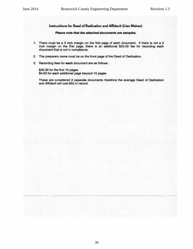
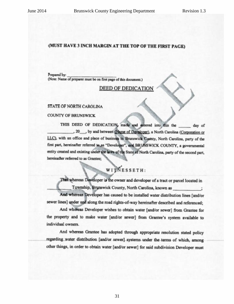
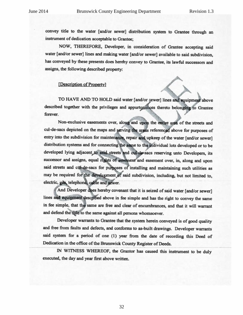
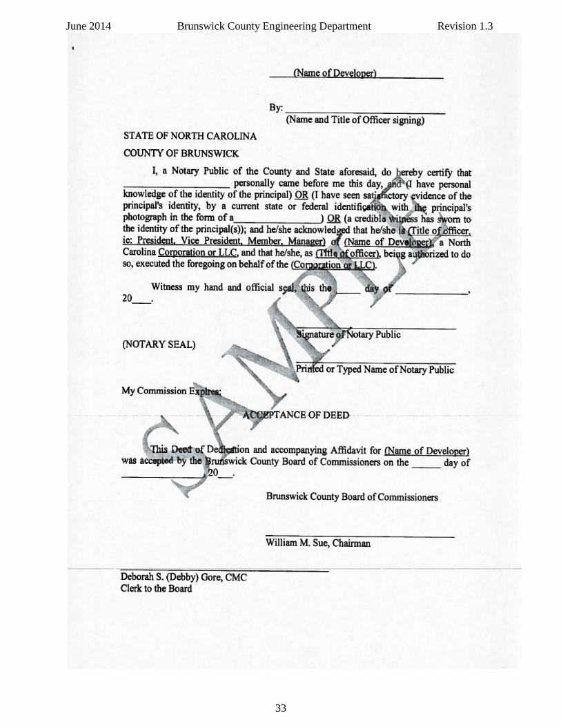
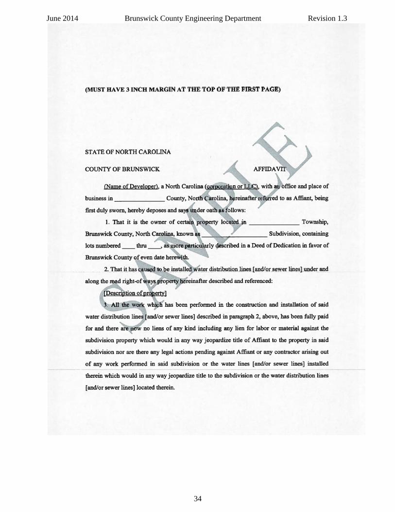
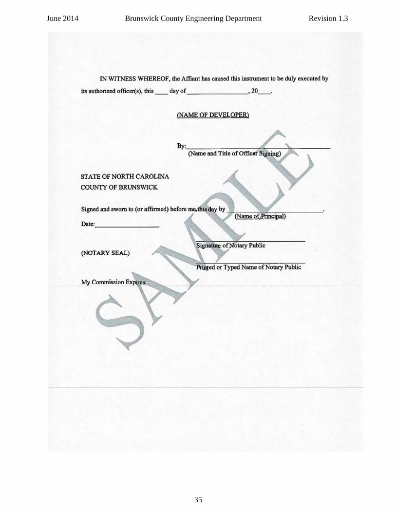
June 2014 Brunswick County Engineering Department Revision 1.3 4) Deed of Dedication & Lien Waiver Affidavit a) As previously stated, for developer installed infrastructure that is permitted in the County’s name, the final dedication to the County will require the submittal of the County’s Deed of Dedication and Lien Waiver Affidavit. b) Contact Brunswick County Engineering Department at 910.253.2500 or [email protected] for further information. c) The County’s Deed of Dedication and Lien Waiver can be found on the County’s website at www.brunsco.net on the County Engineering webpage.
29
June 2014 Brunswick County Engineering Department Revision 1.3
30
June 2014 Brunswick County Engineering Department Revision 1.3
31
June 2014 Brunswick County Engineering Department Revision 1.3
32
June 2014 Brunswick County Engineering Department Revision 1.3
33
June 2014 Brunswick County Engineering Department Revision 1.3
34
June 2014 Brunswick County Engineering Department Revision 1.3
35
June 2014 Brunswick County Engineering Department Revision 1.3 5) Water and Sewer Indemnity Agreements a) As previously stated, for developer installed infrastructure that is permitted in the County’s name, one of the requirements for Substantial Completion of the water and / or sewer infrastructure are for the Developer to execute either the Water Indemnity Agreement or the Sewer Indemnity Agreement, or both forms if both water and sewer was installed. b) Contact Brunswick County Engineering Department at 910.253.2500 or [email protected] for further information. c) The County’s Water Indemnity Agreement and the Sewer Indemnity Agreement can be found on the County website at www.brunsco.net on the County Engineering webpage.
36
June 2014 Brunswick County Engineering Department Revision 1.3
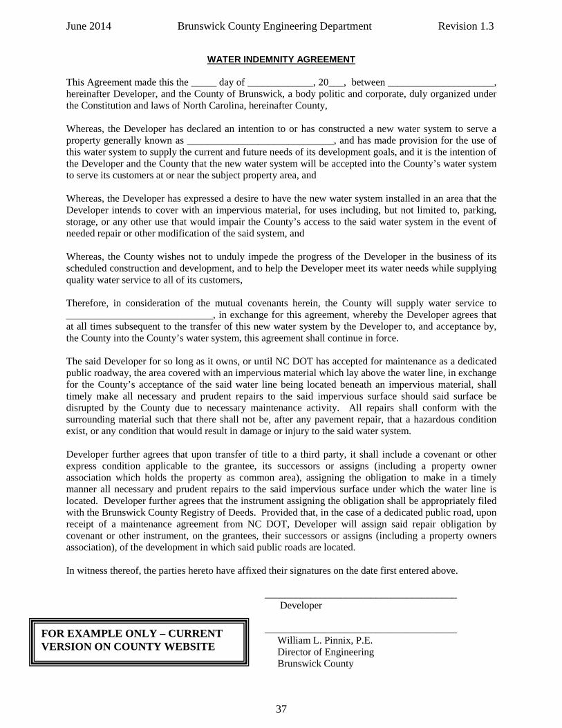
WATER INDEMNITY AGREEMENT
This Agreement made this the _____ day of _____________, 20___, between _____________________, hereinafter Developer, and the County of Brunswick, a body politic and corporate, duly organized under the Constitution and laws of North Carolina, hereinafter County, Whereas, the Developer has declared an intention to or has constructed a new water system to serve a property generally known as _____________________________, and has made provision for the use of this water system to supply the current and future needs of its development goals, and it is the intention of the Developer and the County that the new water system will be accepted into the County’s water system to serve its customers at or near the subject property area, and Whereas, the Developer has expressed a desire to have the new water system installed in an area that the Developer intends to cover with an impervious material, for uses including, but not limited to, parking, storage, or any other use that would impair the County’s access to the said water system in the event of needed repair or other modification of the said system, and Whereas, the County wishes not to unduly impede the progress of the Developer in the business of its scheduled construction and development, and to help the Developer meet its water needs while supplying quality water service to all of its customers, Therefore, in consideration of the mutual covenants herein, the County will supply water service to _____________________________, in exchange for this agreement, whereby the Developer agrees that at all times subsequent to the transfer of this new water system by the Developer to, and acceptance by, the County into the County’s water system, this agreement shall continue in force. The said Developer for so long as it owns, or until NC DOT has accepted for maintenance as a dedicated public roadway, the area covered with an impervious material which lay above the water line, in exchange for the County’s acceptance of the said water line being located beneath an impervious material, shall timely make all necessary and prudent repairs to the said impervious surface should said surface be disrupted by the County due to necessary maintenance activity. All repairs shall conform with the surrounding material such that there shall not be, after any pavement repair, that a hazardous condition exist, or any condition that would result in damage or injury to the said water system. Developer further agrees that upon transfer of title to a third party, it shall include a covenant or other express condition applicable to the grantee, its successors or assigns (including a property owner association which holds the property as common area), assigning the obligation to make in a timely manner all necessary and prudent repairs to the said impervious surface under which the water line is located. Developer further agrees that the instrument assigning the obligation shall be appropriately filed with the Brunswick County Registry of Deeds. Provided that, in the case of a dedicated public road, upon receipt of a maintenance agreement from NC DOT, Developer will assign said repair obligation by covenant or other instrument, on the grantees, their successors or assigns (including a property owners association), of the development in which said public roads are located. In witness thereof, the parties hereto have affixed their signatures on the date first entered above. ______________________________________ Developer ______________________________________ William L. Pinnix, P.E. Director of Engineering Brunswick County
FOR EXAMPLE ONLY – CURRENT VERSION ON COUNTY WEBSITE
37
June 2014 Brunswick County Engineering Department Revision 1.3
SEWER INDEMNITY AGREEMENT
This Agreement made this the _____ day of _____________, 20___, between _____________________, hereinafter Developer, and the County of Brunswick, a body politic and corporate, duly organized under the Constitution and laws of North Carolina, hereinafter County, Whereas, the Developer has declared an intention to or has constructed a new sewer system to serve a property generally known as _____________________________, and has made provision for the use of this sewer system to supply the current and future needs of its development goals, and it is the intention of the Developer and the County that the new sewer system will be accepted into the County’s sewer system to serve its customers at or near the subject property area, and Whereas, the Developer has expressed a desire to have the new sewer system installed in an area that the Developer intends to cover with an impervious material, for uses including, but not limited to, parking, storage, or any other use that would impair the County’s access to the said sewer system in the event of needed repair or other modification of the said system, and Whereas, the County wishes not to unduly impede the progress of the Developer in the business of its scheduled construction and development, and to help the Developer meet its sewer needs while supplying quality sewer service to all of its customers, Therefore, in consideration of the mutual covenants herein, the County will supply sewer service to _____________________________, in exchange for this agreement, whereby the Developer agrees that at all times subsequent to the transfer of this new sewer system by the Developer to, and acceptance by, the County into the County’s sewer system, this agreement shall continue in force. The said Developer for so long as it owns, or until NC DOT has accepted for maintenance as a dedicated public roadway, the area covered with an impervious material which lay above the sewer line, in exchange for the County's acceptance of the said sewer line being located beneath an impervious material, shall timely make all necessary and prudent repairs to the said impervious surface should said surface be disrupted by the County due to necessary maintenance activity. All repairs shall conform with the surrounding material such that there shall not be, after any pavement repair, that a hazardous condition exist, or any condition that would result in damage or injury to the said sewer system. Developer further agrees that upon transfer of title to a third party, it shall include a covenant or other express condition applicable to the grantee, its successors or assigns (including a property owner association which holds title to the property as common area), assigning the obligation to make in a timely manner all necessary and prudent repairs to the said impervious surface under which the sewer line is located. Developer further agrees that the instrument assigning the obligation shall be appropriately filed with the Brunswick County Registry of Deeds. Provided that, in the case of a dedicated public road, upon receipt of a maintenance agreement from NC DOT, Developer will assign said repair obligation by covenant or other instrument, on the grantees, their successors or assigns (including a property owners association), of the development in which said public roads are located. In witness thereof, the parties hereto have affixed their signatures on the date first entered above. ______________________________________ Developer ______________________________________ William L. Pinnix, P.E. Director of Engineering Brunswick County
FOR EXAMPLE ONLY – CURRENT VERSION ON COUNTY WEBSITE
38

June 2014 Brunswick County Engineering Department Revision 1.3
THIS PAGE INTENTIONALLY LEFT BLANK
39
June 2014 Brunswick County Engineering Department Revision 1.3
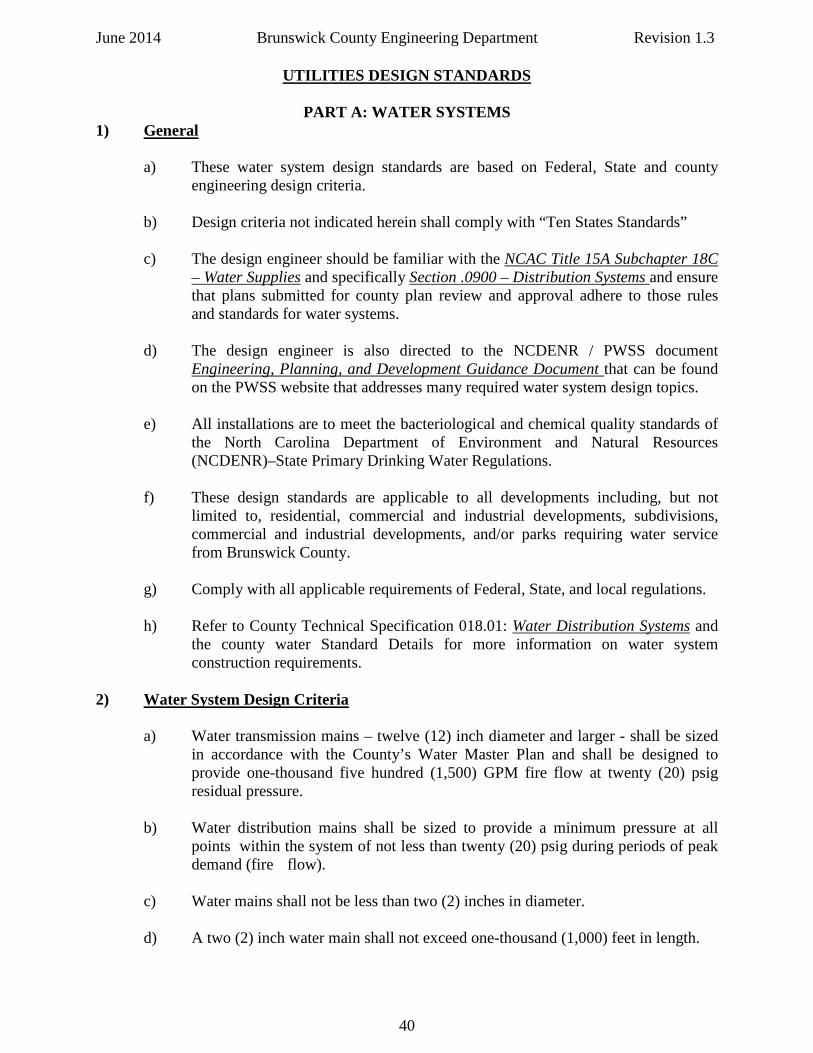
UTILITIES DESIGN STANDARDS
PART A: WATER SYSTEMS 1) General
a) These water system design standards are based on Federal, State and county engineering design criteria.
b) Design criteria not indicated herein shall comply with “Ten States Standards” c) The design engineer should be familiar with the NCAC Title 15A Subchapter 18C
– Water Supplies and specifically Section .0900 – Distribution Systems and ensure that plans submitted for county plan review and approval adhere to those rules and standards for water systems.
d) The design engineer is also directed to the NCDENR / PWSS document
Engineering, Planning, and Development Guidance Document that can be found on the PWSS website that addresses many required water system design topics.
e) All installations are to meet the bacteriological and chemical quality standards of
the North Carolina Department of Environment and Natural Resources (NCDENR)–State Primary Drinking Water Regulations.
f) These design standards are applicable to all developments including, but not
limited to, residential, commercial and industrial developments, subdivisions, commercial and industrial developments, and/or parks requiring water service from Brunswick County.
g) Comply with all applicable requirements of Federal, State, and local regulations. h) Refer to County Technical Specification 018.01: Water Distribution Systems and
the county water Standard Details for more information on water system construction requirements.
2) Water System Design Criteria
a) Water transmission mains – twelve (12) inch diameter and larger - shall be sized in accordance with the County’s Water Master Plan and shall be designed to provide one-thousand five hundred (1,500) GPM fire flow at twenty (20) psig residual pressure.
b) Water distribution mains shall be sized to provide a minimum pressure at all
points within the system of not less than twenty (20) psig during periods of peak demand (fire flow).
c) Water mains shall not be less than two (2) inches in diameter. d) A two (2) inch water main shall not exceed one-thousand (1,000) feet in length.
40
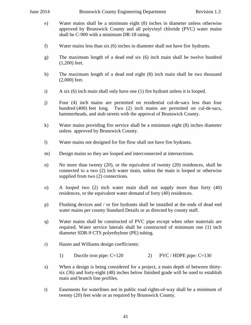
June 2014 Brunswick County Engineering Department Revision 1.3 e) Water mains shall be a minimum eight (8) inches in diameter unless otherwise
approved by Brunswick County and all polyvinyl chloride (PVC) water mains shall be C-900 with a minimum DR-18 rating.
f) Water mains less than six (6) inches in diameter shall not have fire hydrants. g) The maximum length of a dead end six (6) inch main shall be twelve hundred
(1,200) feet. h) The maximum length of a dead end eight (8) inch main shall be two thousand
(2,000) feet. i) A six (6) inch main shall only have one (1) fire hydrant unless it is looped. j) Four (4) inch mains are permitted on residential cul-de-sacs less than four
hundred (400) feet long. Two (2) inch mains are permitted on cul-de-sacs, hammerheads, and stub streets with the approval of Brunswick County.
k) Water mains providing fire service shall be a minimum eight (8) inches diameter
unless approved by Brunswick County. l) Water mains not designed for fire flow shall not have fire hydrants.
m) Design mains so they are looped and interconnected at intersections. n) No more than twenty (20), or the equivalent of twenty (20) residences, shall be
connected to a two (2) inch water main, unless the main is looped or otherwise supplied from two (2) connections.
o) A looped two (2) inch water main shall not supply more than forty (40)
residences, or the equivalent water demand of forty (40) residences. p) Flushing devices and / or fire hydrants shall be installed at the ends of dead end
water mains per county Standard Details or as directed by county staff. q) Water mains shall be constructed of PVC pipe except when other materials are
required. Water service laterals shall be constructed of minimum one (1) inch diameter SDR-9 CTS polyethylene (PE) tubing.
r) Hazen and Williams design coefficients:
1) Ductile iron pipe: C=120 2) PVC / HDPE pipe: C=130
s) When a design is being considered for a project, a main depth of between thirty-
six (36) and forty-eight (48) inches below finished grade will be used to establish main and branch line profiles.
t) Easements for waterlines not in public road rights-of-way shall be a minimum of
twenty (20) feet wide or as required by Brunswick County.
41
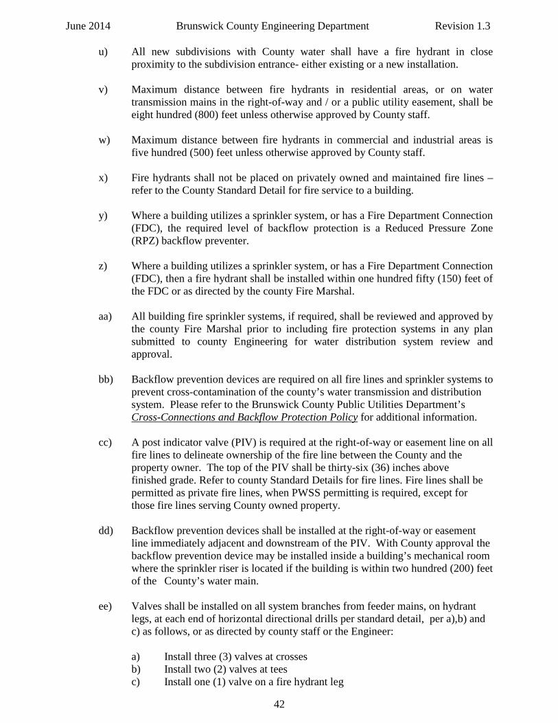
June 2014 Brunswick County Engineering Department Revision 1.3 u) All new subdivisions with County water shall have a fire hydrant in close
proximity to the subdivision entrance- either existing or a new installation. v) Maximum distance between fire hydrants in residential areas, or on water
transmission mains in the right-of-way and / or a public utility easement, shall be eight hundred (800) feet unless otherwise approved by County staff.
w) Maximum distance between fire hydrants in commercial and industrial areas is
five hundred (500) feet unless otherwise approved by County staff. x) Fire hydrants shall not be placed on privately owned and maintained fire lines –
refer to the County Standard Detail for fire service to a building. y) Where a building utilizes a sprinkler system, or has a Fire Department Connection
(FDC), the required level of backflow protection is a Reduced Pressure Zone (RPZ) backflow preventer.
z) Where a building utilizes a sprinkler system, or has a Fire Department Connection
(FDC), then a fire hydrant shall be installed within one hundred fifty (150) feet of the FDC or as directed by the county Fire Marshal.
aa) All building fire sprinkler systems, if required, shall be reviewed and approved by
the county Fire Marshal prior to including fire protection systems in any plan submitted to county Engineering for water distribution system review and approval.
bb) Backflow prevention devices are required on all fire lines and sprinkler systems to prevent cross-contamination of the county’s water transmission and distribution system. Please refer to the Brunswick County Public Utilities Department’s Cross-Connections and Backflow Protection Policy for additional information. cc) A post indicator valve (PIV) is required at the right-of-way or easement line on all fire lines to delineate ownership of the fire line between the County and the property owner. The top of the PIV shall be thirty-six (36) inches above finished grade. Refer to county Standard Details for fire lines. Fire lines shall be permitted as private fire lines, when PWSS permitting is required, except for those fire lines serving County owned property. dd) Backflow prevention devices shall be installed at the right-of-way or easement line immediately adjacent and downstream of the PIV. With County approval the backflow prevention device may be installed inside a building’s mechanical room where the sprinkler riser is located if the building is within two hundred (200) feet of the County’s water main. ee) Valves shall be installed on all system branches from feeder mains, on hydrant legs, at each end of horizontal directional drills per standard detail, per a),b) and c) as follows, or as directed by county staff or the Engineer: a) Install three (3) valves at crosses b) Install two (2) valves at tees c) Install one (1) valve on a fire hydrant leg
42
June 2014 Brunswick County Engineering Department Revision 1.3
ff) For distribution mains isolation valves are required at approximately every one hundred (100) feet per one (1) inch diameter of the installed main up to a maximum distance of two thousand (2,000) feet between valves. For example, for an eight (8) inch diameter main install a main line isolation valve every eight hundred (800) feet. Place main line isolation valves in close proximity to fire hydrants. Also adjust main line isolation valve placement to take into account subdivision entrances, driveways, fences, street intersections, other underground utilities, etc, or as directed by county staff.
gg) For water transmission mains- defined as twelve (12) inches and larger - install an
isolation valve approximately every two hundred (200) feet per one (1) inch diameter of the installed main up to a maximum distance of five thousand (5,000) feet between valves. Place main line isolation valves in close proximity to fire hydrants. Also adjust main line isolation valve placement to take into account subdivision entrances, driveways, fences, street intersections, other underground utilities, etc, or as directed by county staff.
hh) All valves shall open left – no right hand open valves are allowed.
ii) Valves shall be rodded back to the cross or tee if within ten (10) feet of the cross or tee.
jj) Brunswick County is standardizing on the Sensus AMR / AMI water meter. All
water meter boxes used in the service area of Brunswick County Public Utilities must accommodate the Sensus AMR / AMI water meter. Refer to County Standard Details – Water, Sheet 2 of 5, and /or Technical Specification TS 018: Water Distribution Systems – for current water meter box manufacturers and model information.
3) Sizing of Mains
a) System Design and Fire Flow (pipe size six (6) inches and larger):
1) Size piping based on either (1/5) the instantaneous maximum flow plus fire flow or maximum instantaneous demand, whichever is greater. When fire protection is to be provided, system design should be such that fire flows and facilities are in accordance with the requirements of Brunswick County and the state Insurance Service Office (ISO).
2) The minimum acceptable design fire flow for one and two family dwellings shall be one-thousand (1,000) GPM at twenty (20) psig residual pressures. 3) The minimum acceptable design fire flow for other than one and two family dwellings shall be one thousand five hundred (1,500) GPM at twenty (20) psig residual pressure or as approved by the County Fire Marshal and / or the North Carolina State Rating Response System.
43
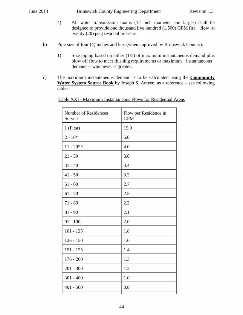
June 2014 Brunswick County Engineering Department Revision 1.3 4) All water transmission mains (12 inch diameter and larger) shall be designed to provide one thousand five hundred (1,500) GPM fire flow at twenty (20) psig residual pressure.
b) Pipe size of four (4) inches and less (when approved by Brunswick County):
1) Size piping based on either (1/5) of maximum instantaneous demand plus blow off flow to meet flushing requirements or maximum instantaneous demand -- whichever is greater.
c) The maximum instantaneous demand is to be calculated using the Community
Water System Source Book by Joseph S. Ameen, as a reference – see following tables:
Table XXI - Maximum Instantaneous Flows for Residential Areas
Number of Residences Served
Flow per Residence in GPM
1 (First)
15.0
2 - 10*
5.0
11 - 20**
4.0
21 - 30
3.8
31 - 40
3.4
41 - 50
3.2
51 - 60
2.7
61 - 70
2.5
71 - 80
2.2
81 - 90
2.1
91 - 100
2.0
101 - 125
1.8
126 - 150
1.6
151 - 175
1.4
176 - 200
1.3
201 - 300
1.2
301 - 400
1.0
401 - 500
0.8
44
June 2014 Brunswick County Engineering Department Revision 1.3 Number of Residences Served
Flow per Residence in GPM
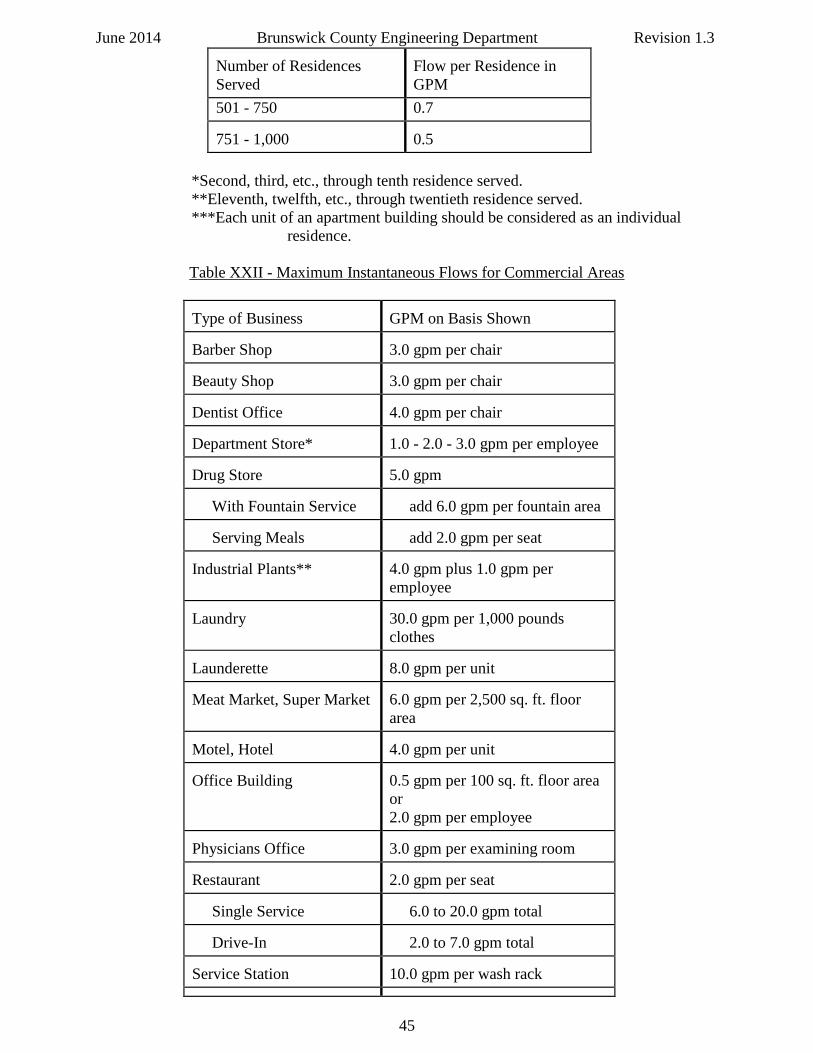
501 - 750 0.7 751 - 1,000
0.5
*Second, third, etc., through tenth residence served. **Eleventh, twelfth, etc., through twentieth residence served.
***Each unit of an apartment building should be considered as an individual residence.
Table XXII - Maximum Instantaneous Flows for Commercial Areas
Type of Business
GPM on Basis Shown
Barber Shop
3.0 gpm per chair
Beauty Shop
3.0 gpm per chair
Dentist Office
4.0 gpm per chair
Department Store*
1.0 - 2.0 - 3.0 gpm per employee
Drug Store
5.0 gpm
With Fountain Service
add 6.0 gpm per fountain area
Serving Meals
add 2.0 gpm per seat
Industrial Plants**
4.0 gpm plus 1.0 gpm per employee
Laundry
30.0 gpm per 1,000 pounds clothes
Launderette
8.0 gpm per unit
Meat Market, Super Market
6.0 gpm per 2,500 sq. ft. floor area
Motel, Hotel
4.0 gpm per unit
Office Building
0.5 gpm per 100 sq. ft. floor area or 2.0 gpm per employee
Physicians Office
3.0 gpm per examining room
Restaurant
2.0 gpm per seat
Single Service
6.0 to 20.0 gpm total
Drive-In
2.0 to 7.0 gpm total
Service Station
10.0 gpm per wash rack
45
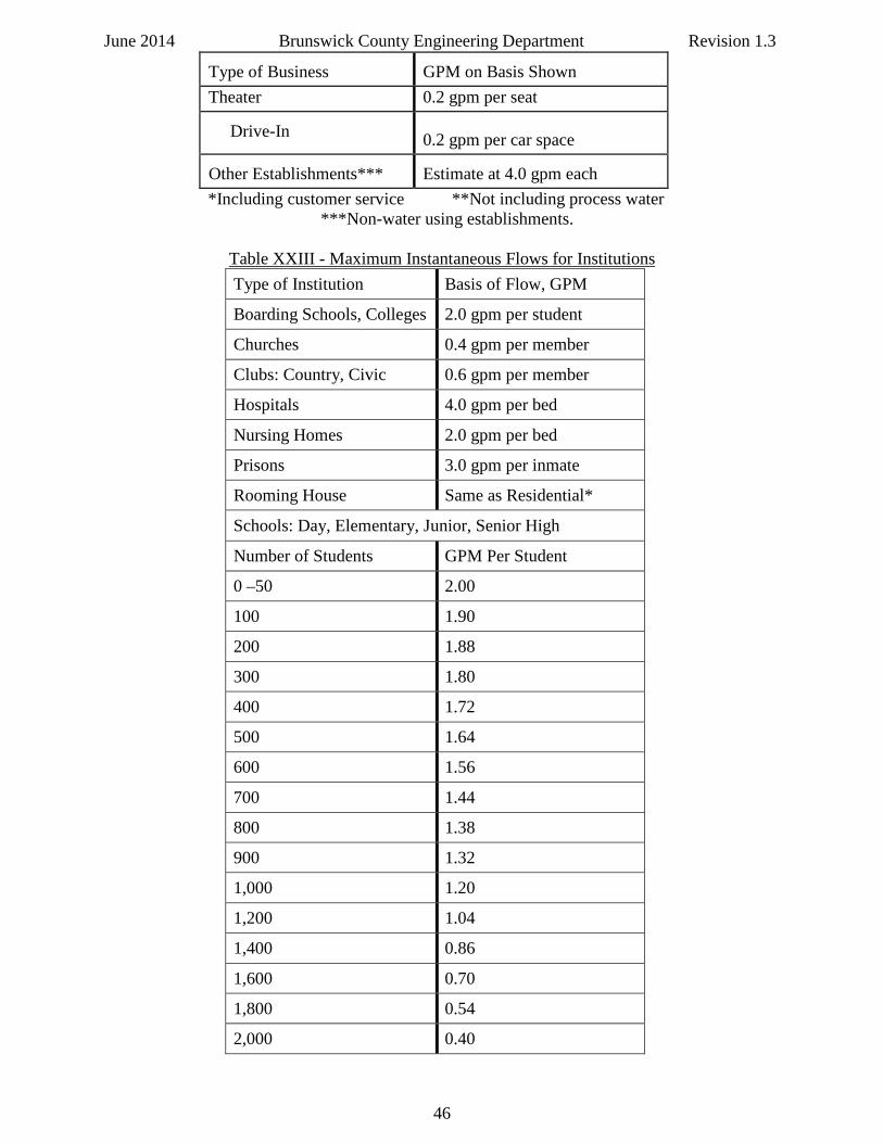
June 2014 Brunswick County Engineering Department Revision 1.3 Type of Business
GPM on Basis Shown
Theater 0.2 gpm per seat Drive-In
0.2 gpm per car space
Other Establishments***
Estimate at 4.0 gpm each
*Including customer service **Not including process water ***Non-water using establishments.
Table XXIII - Maximum Instantaneous Flows for Institutions Type of Institution Basis of Flow, GPM
Boarding Schools, Colleges 2.0 gpm per student
Churches 0.4 gpm per member
Clubs: Country, Civic 0.6 gpm per member
Hospitals 4.0 gpm per bed
Nursing Homes 2.0 gpm per bed
Prisons 3.0 gpm per inmate
Rooming House Same as Residential*
Schools: Day, Elementary, Junior, Senior High
Number of Students GPM Per Student
0 –50 2.00
100 1.90
200 1.88
300 1.80
400 1.72
500 1.64
600 1.56
700 1.44
800 1.38
900 1.32
1,000 1.20
1,200 1.04
1,400 0.86
1,600 0.70
1,800 0.54
2,000 0.40
46
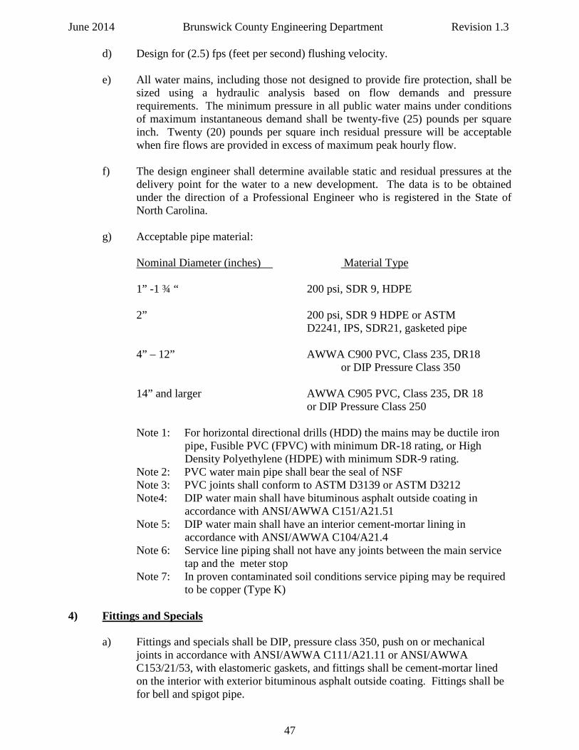
June 2014 Brunswick County Engineering Department Revision 1.3 d) Design for (2.5) fps (feet per second) flushing velocity.
e) All water mains, including those not designed to provide fire protection, shall be
sized using a hydraulic analysis based on flow demands and pressure requirements. The minimum pressure in all public water mains under conditions of maximum instantaneous demand shall be twenty-five (25) pounds per square inch. Twenty (20) pounds per square inch residual pressure will be acceptable when fire flows are provided in excess of maximum peak hourly flow.
f) The design engineer shall determine available static and residual pressures at the
delivery point for the water to a new development. The data is to be obtained under the direction of a Professional Engineer who is registered in the State of North Carolina.
g) Acceptable pipe material: Nominal Diameter (inches) Material Type 1” -1 ¾ “ 200 psi, SDR 9, HDPE 2” 200 psi, SDR 9 HDPE or ASTM D2241, IPS, SDR21, gasketed pipe 4” – 12” AWWA C900 PVC, Class 235, DR18
or DIP Pressure Class 350 14” and larger AWWA C905 PVC, Class 235, DR 18 or DIP Pressure Class 250 Note 1: For horizontal directional drills (HDD) the mains may be ductile iron
pipe , Fusible PVC (FPVC) with minimum DR-18 rating, or High Density Polyethylene (HDPE) with minimum SDR-9 rating.
Note 2: PVC water main pipe shall bear the seal of NSF Note 3: PVC joints shall conform to ASTM D3139 or ASTM D3212 Note4: DIP water main shall have bituminous asphalt outside coating in
accordance with ANSI/AWWA C151/A21.51 Note 5: DIP water main shall have an interior cement-mortar lining in accordance with ANSI/AWWA C104/A21.4 Note 6: Service line piping shall not have any joints between the main service tap and the meter stop Note 7: In proven contaminated soil conditions service piping may be required to be copper (Type K)
4) Fittings and Specials a) Fittings and specials shall be DIP, pressure class 350, push on or mechanical joints in accordance with ANSI/AWWA C111/A21.11 or ANSI/AWWA C153/21/53, with elastomeric gaskets, and fittings shall be cement-mortar lined on the interior with exterior bituminous asphalt outside coating. Fittings shall be for bell and spigot pipe.
47
June 2014 Brunswick County Engineering Department Revision 1.3 5) Materials and Requirements for Restrained Joints, Pipes, and Fittings on Water Systems
a) Restrained joints are required to prevent movement of system piping caused by forces in or on buried piping tees, valves, branches, bends, plugs, etc.
b) Restrained joints shall be installed as shown on the approved plans, standard
details, or as directed by county staff or the Engineer.
c) Concrete thrust blocking shall be installed as shown on the approved plans, standard details, or as directed by county staff or the Engineer.
d) All carrier pipe installed inside a casing shall be pressure class 350 ductile iron
pipe per county standard details with restrained joints.
e) All restrained joint systems shall have a pressure rating equal to or greater than that of the pipe on which they are installed.
f) Restraint type gaskets that provide internal restraint by means of stainless steel
inserts embedded within the gasket are not permitted for use in Brunswick County.
g) Ductile Iron Pipe (DIP)
1) Install restraints in strict accordance with the manufacturer’s recommendations.
2) All ductile iron horizontal directional drill and bore-and-jack installations
shall use boltless, integral, positive locking restraint systems that allow for joint deflection and disassembly should the need arise. The restrained joint system shall be a manufacturer’s standard restrained joint system such as American (Flex-Ring or Lok-Ring), U S Pipe (TR-Flex), or Griffin (Snap-Lok), or approved equal.
Note: the aforementioned boltless, integral, positive locking restraint systems are also acceptable for use in open cut pipe installation locations.
3) External bell restraint harness shall have ductile iron glands. The dimensions of the gland shall be such that it can be used with the standard mechanical joint bell. Twist off nuts with preset factory torque setting shall be used to ensure proper actuation of the restraint device. All nuts, bolts, and fasteners shall be high strength alloy steel. Mechanical joint restraints shall conform to ANSI/AWWA A21.11/C111 and ANSI/AWWA A21.53/C153, latest revision.
The restrained joint system shall be a manufacturer’s standard restrained
joint system manufactured by EBAA Iron, Inc., Smith-Blair, Inc., JCM, Inc., or approved equal.
48
June 2014 Brunswick County Engineering Department Revision 1.3
4) Restraint for valves and fittings shall have ductile iron glands. Twist off nuts with preset factory torque setting shall be used to ensure proper actuation of the restraint device. All nuts, bolts, and fasteners shall be high strength alloy steel. Mechanical joint restraints shall conform to ANSI/AWWA A21.11/C111 and ANSI/AWWA A21.53/C153, latest revision.
The restrained joint system shall be a manufacturer’s standard restrained
joint system manufactured by EBAA Iron, Inc., Smith-Blair, Inc., JCM, Inc., or approved equal.
5) Stainless steel rodding and fasteners, Type 304 minimum, is acceptable
per county standard details. Manufacturer’s restraint system and / or glands are preferred in lieu of rodding.
h) Polyvinyl Chloride Pipe (PVC)
1) Install restraints in strict accordance with the manufacturer’s recommendations.
2) External bell restraint harness shall have ductile iron glands. The
dimensions of the gland shall be such that it can be used with the standard mechanical joint bell. Twist off nuts with preset factory torque setting shall be used to ensure proper actuation of the restraint device. All nuts, bolts, and fasteners shall be high strength alloy steel. Mechanical joint restraints shall conform to ANSI/AWWA A21.11/C111 and ANSI/AWWA A21.53/C153, latest revision.
The restrained joint system shall be a manufacturer’s standard restrained
joint system manufactured by EBAA Iron, Inc., Smith-Blair, Inc., JCM, Inc., or approved equal.
3) Restraint for valves and fittings shall have ductile iron glands. Twist off
nuts with preset factory torque setting shall be used to ensure proper actuation of the restraint device. All nuts, bolts, and fasteners shall be high strength alloy steel. Mechanical joint restraints shall conform to ANSI/AWWA A21.11/C111 and ANSI/AWWA A21.53/C153, latest revision.
The restrained joint system shall be a manufacturer’s standard restrained
joint system manufactured by EBAA Iron, Inc., Smith-Blair, Inc., JCM, Inc., or approved equal.
4) Stainless steel rodding and fasteners, Type 304 minimum, is acceptable
per county standard details. Manufacturer’s restraint system and/or glands are preferred in lieu of rodding.
6) Valves
a) Provide two (2) valves for a tee intersection, (3) valves for a cross, and four (4) valves for two-offset tee intersections.
49
June 2014 Brunswick County Engineering Department Revision 1.3 b) Sufficient main valves shall be provided on water mains so that the number of
County water customers out of service due to a main break or maintenance activity is minimized. Refer to Section 2 ff) and 2 gg) for required valve spacing.
c) Brunswick County reserves the right to require additional valves on any design if
it is deemed in the best interest of current and future county water customers. d) Valves shall be properly located, operable, and at the correct elevation. All valves
and reducers shall be bolted or rodded to the tee or cross. Thrust blocking or other restraining methods shall be installed per standard details.
e) The maximum depth of the valve nut shall be five (5) feet. When valve extension
kits are used they must be manufactured by the same company that manufactured the
valve. f) Valve boxes shall be cast iron, adjustable, screw type with a lid marked WATER. The valve box shall be centered over the wrench nut and seated on compacted
backfill with a masonry brick under the valve box for support as shown on the standard details. Valve boxes shall not rest directly on the bonnet of the valve.
g) The valve box shall not touch the valve assembly. Valve boxes shall be brought
flush to finished grade. Concrete valve markers are required except inside platted subdivisions and on fire hydrant gate valves.
h) All valve boxes in traffic bearing areas shall be encased in a precast concrete pad of (3,000) psi concrete beneath the asphalt. Precast concrete valve box
encasements may be used for valve box encasement outside of traffic bearing areas.
i) Provide one (1) valve for each fire hydrant branch.
j) All valves shall be minimum two (2) inch diameter.
7) Industrial or Special Design Conditions
a) Design of water systems for industrial or other systems not covered in this section shall be approved on a special case basis only. Special requests shall be submitted to the Brunswick County Engineering Department for review.
8) Dead End Mains
a) Minimize dead end mains by looping of all mains whenever possible. b) Where permanent dead ends occur: provide a fire hydrant, water line stubout for
future line extension, an automatic flushing device on lines six (6) inches and larger, or a manual flushing device on lines less than six (6) inches in diameter. Flushing devices should be sized to provide flows which will give a velocity of at least (2.5) feet per second in the water main being flushed. A flushing device may be required to be an automatic type with UV resistant cover at the discretion of the County. See County Standard Water Details for further information.
50
June 2014 Brunswick County Engineering Department Revision 1.3 c) Do not connect any flushing device to any sanitary or storm sewer or any other
non-approved connection.
9) Separation of Water Mains and Sewer Mains a) Horizontal and Vertical Separation 1) Minimum horizontal separation between water mains and sanitary sewer
shall be ten (10) feet. The distance shall be measured edge of pipe to edge of pipe.
2) Should ten (10) foot separation not be feasible, then the water main may
be located closer to the sewer main provided that:
a) It is laid in a separate trench,
b) It is laid in the same trench with the water main located at one side on a bench of undisturbed earth,
c) In either of the above cases, crown elevation of the sewer main
shall be at least eighteen (18) inches below invert elevation of the water main.
3) Sewer mains crossing water mains shall be laid to provide a minimum
vertical separation of eighteen (18) inches between the invert of the water main and the crown elevation of the sewer main. The crossing shall be arranged perpendicularly so that the sewer main joints will be equidistant and at least ten (10) feet from the crossing in each direction.
4) If it is impossible to maintain the required horizontal and vertical
separation as described above, or anytime sewer must be laid above a water main, then both the water main and sewer main must be constructed of pressure class 350 ductile iron pipe with watertight joints and pressure tested to (150) psi to assure water tightness before backfilling. At the discretion of Brunswick County a ferrous sleeve may be installed around existing water mains and force mains to meet this requirement provided DENR approval for the ferrous sleeve is first obtained by the Engineer.
5) Mechanical joints will be required for the transition in the sewer main at
water main / sewer main crossings. Fernco couplings are not permitted to be used. Special structural support for the water and sewer mains may be required.
b) Special Cases involving water mains:
1) Water mains may not be placed in contaminated areas unless piping
material, including gaskets, are adequate to protect the water quality
2) Water mains may not be less than ten (10) feet from any waste water tile field or spray field.
51
June 2014 Brunswick County Engineering Department Revision 1.3 3) There may not be any connection between the water distribution system
and any pipes, pumps, hydrants, or tanks whereby unsafe water or other contaminated materials may be discharged or drawn into the system.
4) Neither steam condensate nor cooling water from jackets or other heat
exchange devices may be returned to the potable water supply.
10) Water Main, Sewer Main, and Storm Drainage System Interference Manholes
a) No water pipe shall pass through or come in contact with any part of a sewer manhole or storm drainage pipe or structure.
11) Exceptions a) Brunswick County Engineering must specifically approve any variance from any separation requirements when it is impossible to obtain the specified distances as stated herein. 12) Surface Water and Wetlands Crossings
a) Surface water and wetland crossings, whether over or under water, present special challenges. Brunswick County Engineering Department should be consulted before plans are prepared. Water mains crossing surface waters must be adequately supported and anchored, protected from damage and freezing, and be accessible for repair or replacement. Any support or anchoring system should be designed to be corrosion resistant using concrete and / or minimum Type 304 stainless steel. Water mains crossing under water bodies must maintain a minimum cover of three (3) feet from the deepest point to the crown of the pipe. When crossing water courses which are greater than fifteen (15) feet in width, the following must be provided:
1) The pipe material and joints shall be designed appropriately.
2) Valves must be located so that the section can be isolated for testing or
repair; the valves must be easily accessible, and not subject to flooding. 3) An automatic flushing device must be provided on the side opposite the
supply service. 13) Thrust Block Design
a) Maximum soil pressure: 1,000 lbs/sq ft.
b) Minimum water pressure: 150 psi.
c) Safety factor: 1.5.
d) Concrete: 2500 psi minimum
e) Refer to Water Standard Details for thrust blocking detail information.
52
June 2014 Brunswick County Engineering Department Revision 1.3 14) Cover Over Water Mains
a) Provide suitable cover on all water mains. Minimal cover depth for PVC pipe is thirty-six (36) inches – use ductile iron pipe if (36) inches depth of cover cannot be obtained for PVC pipe:
1) 4" - 24" diameter main: 36 inch minimum cover.
2) 30" diameter and larger main: 48 inches minimum cover. 3) All piping located within a public right-of-way shall be constructed in
accordance with applicable permits and Brunswick County’s minimum requirements.
4) Special conditions other than those listed above may be approved if
requested in writing from the Brunswick County. 5) No berms shall be placed over utility lines.
15) Tap Size in Relation to Main Size
a) As a general rule all water service taps shall be a minimum of one size smaller than the water main being tapped. In the case where the water service tap is the same size as the main being tapped a tapping sleeve, approved by County Engineering, must be utilized instead of a tapping saddle. Brunswick County reserves the right to stipulate the maximum size tap available off of any water main, or to require a cut-in tee instead of a tapping sleeve. It may be necessary to schedule a water system shutdown and install a main line tee versus a tapping saddle or tapping sleeve if the County requires the full size cut in tee.
b) Horizontal directionally drilled (HDD) pipe shall not have service taps.
16) Combination Air Valves
a) Mains shall be designed to minimize high points. At high points in water mains where there are no service taps within (2,000) feet, and where air can accumulate, provisions shall be made to remove the air by means of a combination air valve. Combination air valves shall not be used in situations where flooding of the manhole or chamber may occur. Air valves should be sized based on the size of the water main. Air valves should be detailed on the design drawings and approved by Brunswick County. Air valves shall be installed per county standard details.
17) Water Main Flushing Assemblies
a) All dead-end water mains shall be designed to include a standard flushing device. Mains six (6) inches and larger require an automatic flushing device. A standard fire hydrant or other approved flushing device must be utilized for main flushing. A temporary flushing device may be utilized in cases where the main is to be extended at a later date with approval of Brunswick County.
53
June 2014 Brunswick County Engineering Department Revision 1.3 b) Flushing devices and other such appurtenances to a water distribution system
shall not be connected directly to any storm drain or sanitary sewer. Blow-off chambers must include a removable extension to direct the water away from the blow-off box.
c) Refer to county standard details for additional information.
18) Water Services a) Water meters shall be installed for all service connections to water mains.
b) Brunswick County is standardizing on the Sensus AMI / AMR meter – see
County Engineering for any questions concerning proper meter selection.
c) All commercial and industrial service connections shall be sized appropriately and provided with fire service as required by local building codes. See location schematic standard detail.
d) All non-residential water meters and all irrigation water meters must have an
approved backflow cross-connection protective device installed to protect the County water distribution system against cross – contamination.
e) All new in-ground irrigation systems on lots platted and recorded after July 1, 2009 (ref: NCGS 143-355.4) are required to have a separate water meter for the irrigation system.
f) All new developments that will have public sewer in addition to public water are required to have a double water meter box on each lot to accommodate both the domestic and irrigation water meters – refer to county standard water meter details.
19) Utility Easements and Rights-of-Way
a) No trees or shrubs shall be planted in utility rights-of-way and/or public utility easements.
b) No privacy berms or berms of any kind shall be placed in utility rights-of-way and/or public utility easements.
c) No permanent structures or fencing shall be placed in utility rights-of-way and/or public utility easements. d) Public utility easements shall be a minimum twenty (20) feet wide unless prior approval is obtained from Brunswick County Engineering.
20) Valve Markers
a) Concrete valve markers shall be placed, in public rights-of-way, behind all valve boxes not installed for individual, residential, or commercial connection. Fire hydrant isolation valves are not required to have a concrete valve marker.
54
June 2014 Brunswick County Engineering Department Revision 1.3 Fiberglass valve markers may be utilized in utility easements. Refer to County
Standard Details. 21) Existing Driveways
a) For new utility lines crossing existing concrete or asphalt driveways, concrete driveways shall be removed and reinstalled to nearest expansion joints and asphalt drives shall be saw-cut and replaced to minimum three (3) feet from each side of the open excavation for the utility line installation.
22) Fire Hydrants
a) All hydrants shall be installed on a minimum six (6) inch water line and should be installed in close proximity to road intersections whenever possible. Only one (1) fire hydrant may be installed when the line is served by a six (6) inch tap and is not looped to another main. When placed at intersections hydrants shall be offset from the top of the intersection to minimize vehicular strikes to the hydrant. The minimum acceptable flow for fire hydrants is one thousand (1,000) gpm with twenty (20) psi residual pressure for residential and one-thousand-five-hundred (1,500) gpm with twenty (20) psi residual pressure for all other areas unless otherwise specified by the County Fire Marshal. The Engineer shall contact the local fire department and/or the County Fire Marshal during the design phase to coordinate the proper location of all fire hydrants within the project area.
b) In residential areas the maximum distance between fire hydrants, measured along street centerlines, shall be eight hundred (800) feet, unless otherwise approved by the County Fire Marshal. c) All new residential subdivisions shall have a fire hydrant placed at the entrance to the subdivision and thereafter a maximum of eight-hundred (800) feet apart.
d) In commercial, business, office, institutional and industrial zoning the maximum
distance between hydrants, measured along street centerlines, shall be five-hundred (500) feet, unless otherwise approved by the County Fire Marshal.
New buildings or additions that result in a total building area of ten-thousand
(10,000) square feet require hydrants to be installed at three-hundred (300) foot intervals along sides of the building that are accessible to fire jumpers. These hydrants shall be at least fifty (50) feet away from the building.
e) Where sprinkler systems are used, a fire department connection (FDC) shall be
installed and shall be within one hundred fifty (150) feet of an accessible fire hydrant, or as directed by the County Fire Marshal.
23) Automatic Fire Sprinkler Systems
a) All automatic fire sprinkler systems shall be approved by the County Fire Marshal. Design engineers shall obtain Fire Marshal review and approval as part of the plan review process prior to obtaining County Engineering plan review approval.
55
June 2014 Brunswick County Engineering Department Revision 1.3
b) When a fire protection system is proposed the type of backflow prevention assembly to be installed to protect the public water supply shall be commensurate with the degree of any actual or potential hazard. At a minimum the backflow protection device will consist of a double check detector valve assembly. Refer to Section W: “Cross – Connections and Backflow Protection Policy.
c) All backflow protection devices for automatic fire sprinklers will meet the
requirements listed in the Brunswick County Public Utilities Department “Cross – Connections and Backflow Protection Policy. At a minimum the backflow protection device will consist of a double check valve detector assembly including (2) check valves, (2) OS&Y gate valves, and (4) test cocks. All fire systems using toxic additives or booster pumping facilities shall be required to be protected with an approved reduced pressure principle assembly (RPZ or RP). These backflow prevention assemblies shall be American Water Works Association (AWWA), National Fire Protection Association (NFPA), and the Foundation for Cross Control and Hydraulic Research of the University of Southern California (FCCCHR-USC) approved. All fire sprinkler backflow protection devices shall be installed on the supply side of the sprinkler fire protection line.
d) The backflow prevention assembly shall be installed on the back side of the right-
of-way on the customer’s side of the water service and shall be installed above ground in an insulated box and shall be operated and maintain by the customer at his or her expense. No underground installations will be approved or accepted. If the building is (200) linear feet or less from the water main serving the building then the backflow prevention device may be installed inside the building.
e) A post indicator valve (PIV) shall be provided at the right-of-way line or edge of
easement line. The top of the PIV shall be thirty-six (36) inches above finished grade. The County shall own and maintain up to and including the PIV but not beyond the PIV on private property.
f) Where automatic fire sprinkler systems are used a fire department connection
(FDC) shall be provided at the direction of the County Fire Marshal. The FDC shall be located within one hundred fifty (150) feet of a fire hydrant, or as directed by the County Fire Marshal. When a sprinkler system serves only a part of a large structure, the FDC shall be labeled, with minimum (2) inch letters on a permanent sign, as to which section of the structure that sprinkler riser serves. Remote FDCs may be installed (versus wall mounted FDCs) with the approval of the County Fire Marshal – refer to County Water Standard Details.
24) Cross Connection and Backflow Protection Policy
a) Refer to the Brunswick County Public Utilities Department Cross –Connection and Backflow Protection Policy for a complete understanding of the required protection for County water mains for any proposed design.
b) The intent of this policy is to define the authority of Brunswick County as the
water purveyor, in the elimination of all hazards, both actual and potential, to the potable water within the County’s public water supply system.
56
June 2014 Brunswick County Engineering Department Revision 1.3
c) All commercial and industrial customers must have an approved backflow prevention device.
d) All irrigation systems must have an approved backflow prevention device.
25) New In-Ground Irrigation Systems
a) All new in-ground irrigation systems must have their own separate water meter with an approved backflow prevention device.
26) Locate Tape, Wire, and Electronic Marker Balls
a) Tape shall be three (3) inches wide, blue in color, bearing continuous message “CAUTION WATER LINE BURIED BELOW”. Tape shall be made of plastic or other permanent material, and shall be buried continuously above the water main at a depth of eighteen (18) inches below finished grade.
b) All water mains shall have a #12 AWG, high strength copper clad steel conductor
(HS-CCS) such as Copperhead Superflex, or approved equal, with HDPE insulation, and rated for direct burial. Listed and approved underground connectors shall be used for all splices. The wire shall be brought up in valve boxes per County Standard Detail. In any event, the wire shall be brought up into a valve box at 1,000 feet maximum intervals to provide wire access points. The wire shall be taped to the top of the water main at minimum ten (10) feet intervals.
c) The contractor shall be required to perform a signal strength test of the installed
tracer wire at the end of the project with County staff present. Refer to County Standard Details for tracer wire information.
d) Individual water services shall have tracer wire installed from the main to the
meter box. e) In addition to the tracing wire, electronic marker balls shall be installed on the
water main in accordance with Brunswick County Technical Specification TS 035.01: Electronic Markers for Water and Sewer Pressure Mains.
57
June 2014 Brunswick County Engineering Department Revision 1.3
UTILITIES DESIGN STANDARDS
PART B: GRAVITY SEWER SYSTEMS 1) General
a) The following sanitary sewer system design standards are based on Federal, State and local health requirements and Brunswick County engineering design criteria.
b) These design standards are applicable to all developments including but not
limited to residential, commercial and industrial developments, subdivisions and/or parks requiring sanitary sewer service from Brunswick County.
2) Gravity Sewer System Design Criteria
a) Minimum main line size for public sewer mains is eight (8) inches. Minimum main line size for private sewer mains is six (6) inches.
b) Service lines:
1) Single 4” or 6” PVC or DIP service lateral per residential unit. 2) A single 6” service line may serve two residential units upon specific
approval from County Engineering. 3) Commercial units utilize a single 6” service lateral. 4) Multi-family units shall have services designed by an engineer and may
utilize an 8”service line. 5) 8” service lines shall connect to a manhole only and not to a main. 6) No Fernco couplings allowed on sewer mains or service laterals.
c) Minimum Pipe Slope in Feet per Thousand Feet (Ft / 1000):
1) Gravity Sewer mains
a) 8-inch: 4 feet (= 0.40%) b) 10-inch: 2.8 feet (= 0.28%) c) 12-inch: 2.2 feet (= 0.22%) d) 15-inch: 1.5 feet (= 0.15%) e) 18-inch: 1.2 feet (= 0.12%) f) 20-inch or 21-inch: 1.0 foot (= 0.10%) g) 24-inch: 0.8 foot (=0.08%)
2) Service lines:
a) 6-inch: 1.0% b) 8-inch: 0.4%
Note: Sewers shall not be oversized to justify using flatter slopes.
58
June 2014 Brunswick County Engineering Department Revision 1.3 3) Capacity Design
a) Minimum flow for residential or apartment unit: 360 gallons per day per unit. b) All other flows: comply with the unit contributory loading criteria, North Carolina
Department of Environment and Natural Resources (NCDENR) regulations. 4) Sewer Mains
a) Straight alignment and uniform slope between manholes – no exceptions.
b) Depth adequate to receive wastewater from the lowest service and to prevent freezing.
c) If slopes are greater than twenty (20) percent then anchor using concrete blocking.
d) Where two or more mains of different diameters enter a sanitary manhole it is
required to match the crown elevations of the different size pipes. e) Service laterals to be a minimum of five (5) feet from each property corner pin
and as far from water laterals as possible depending on site conditions. f) Locate sewer mains and manholes outside of paved roadways whenever possible.
5) Separation of Sewer Mains and Water Mains a) Horizontal and Vertical Separation 1) Minimum horizontal separation between water mains and sanitary sewer
mains shall be ten (10) feet. The distance shall be measured edge of pipe to edge of pipe.
2) Should ten (10) foot separation not be feasible, then the water main may
be located closer to the sewer main provided that:
a) It is laid in a separate trench,
b) It is laid in the same trench with the water main located at one side on a bench of undistributed earth,
c) In either of the above cases, crown elevation of the sewer shall be
at least eighteen (18) inches below invert elevation of the water line.
3) Sewer mains crossing water mains shall be laid to provide a minimum
vertical separation of eighteen (18) inches between the invert of the water main and the crown elevation of the sewer main. The crossing shall be arranged perpendicularly so that the sewer main joints will be equidistant and at least ten (10) feet from the crossing in each direction.
59
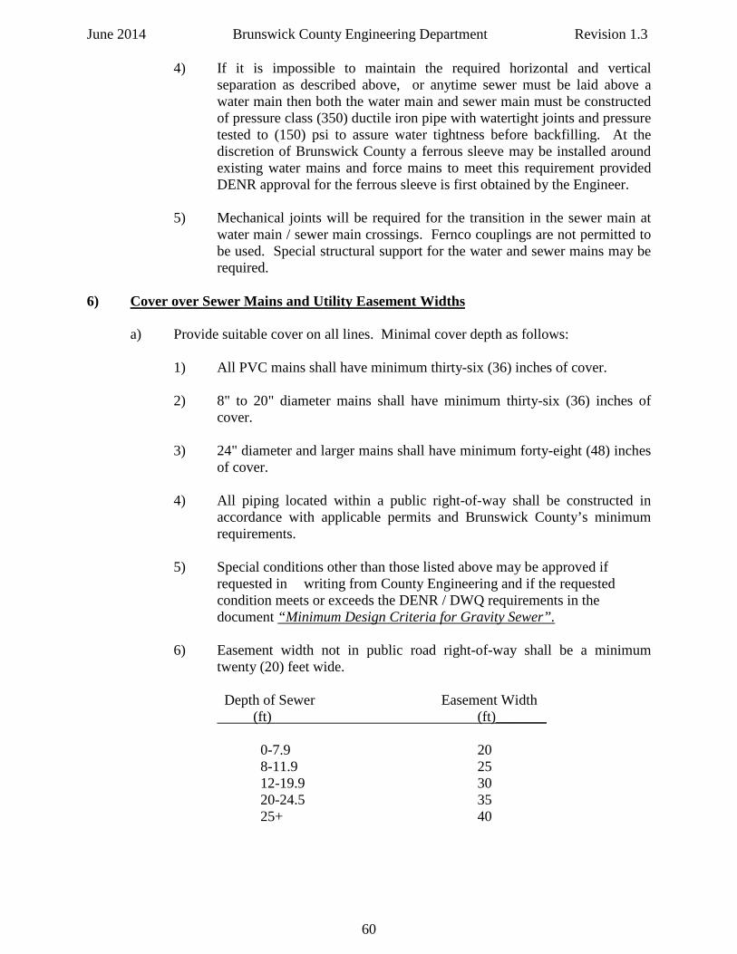
June 2014 Brunswick County Engineering Department Revision 1.3 4) If it is impossible to maintain the required horizontal and vertical
separation as described above, or anytime sewer must be laid above a water main then both the water main and sewer main must be constructed of pressure class (350) ductile iron pipe with watertight joints and pressure tested to (150) psi to assure water tightness before backfilling. At the discretion of Brunswick County a ferrous sleeve may be installed around existing water mains and force mains to meet this requirement provided DENR approval for the ferrous sleeve is first obtained by the Engineer.
5) Mechanical joints will be required for the transition in the sewer main at
water main / sewer main crossings. Fernco couplings are not permitted to be used. Special structural support for the water and sewer mains may be required.
6) Cover over Sewer Mains and Utility Easement Widths
a) Provide suitable cover on all lines. Minimal cover depth as follows:
1) All PVC mains shall have minimum thirty-six (36) inches of cover.
2) 8" to 20" diameter mains shall have minimum thirty-six (36) inches of cover.
3) 24" diameter and larger mains shall have minimum forty-eight (48) inches
of cover.
4) All piping located within a public right-of-way shall be constructed in accordance with applicable permits and Brunswick County’s minimum requirements.
5) Special conditions other than those listed above may be approved if requested in writing from County Engineering and if the requested condition meets or exceeds the DENR / DWQ requirements in the document “Minimum Design Criteria for Gravity Sewer”.
6) Easement width not in public road right-of-way shall be a minimum twenty (20) feet wide.
Depth of Sewer Easement Width
(ft) (ft)_______ 0-7.9 20 8-11.9 25 12-19.9 30 20-24.5 35 25+ 40
60
June 2014 Brunswick County Engineering Department Revision 1.3 7) Ductile Iron Pipe (DIP) required usage
a) Use ductile iron pipe where sanitary sewer:
1) Has a depth of cover less than thirty-six (36) inches. 2) Has a depth of cover greater than eighteen (18) feet.
3) Crosses beneath storm drain pipe with less than twenty-four (24) inches of
clearance – refer to County Standard Details for additional information.
4) Crosses above storm drainage or other pipe with less than two (2) feet of clearance.
5) Crosses creeks, rivers and other water bodies unless another pipe material
is specified by County Engineering. 6) Is installed within a casing pipe. 7) Cover is less than the minimum prescribed in Section F above. 8) Crosses through storm sewer interference junction boxes.
8) Sewer Manholes
a) Manhole diameters:
1) Up to eight (8) feet deep: minimum diameter four (4) feet. 2) Greater than eight (8) feet deep: minimum diameter five (5) feet. 3) Inside drop manholes: minimum diameter five (5) feet.
b) Extended bases are required on manhole base sections – see Standard Details.
c) Maximum manhole spacing: (400) feet standard – other spacing as requested and approved by County Engineering in accordance with DENR / DWQ regulations.
d) Minimal angle between sewer mains intersecting at manhole: (90) degrees or
greater to the downstream side – variances allowed by approval of County Engineering.
e) Manhole top elevations:
1) Shall be at or above finished grade elevation. 2) Set to match finished pavement grade if located in paved areas.
g) Use inside drop manholes where the difference in incoming and outgoing pipe
invert elevation is 30 inches or greater.
61
June 2014 Brunswick County Engineering Department Revision 1.3 h) Eccentric manhole cones on all manholes with 24 inch clear opening on the ring and cover.
i) Use water tight ring and covers in flood plan areas or areas subject to flooding.
j) Use shallow precast manholes with flat tops where necessary and approved by County Engineering. k) Provide 0.1 foot elevation fall through all manholes except straight through manholes. l) Manholes shall be coated with coal tar epoxy coating minimum 20 mils thick. m) Use vented manholes as required per DENR / DWQ requirements.
62
June 2014 Brunswick County Engineering Department Revision 1.3
UTILITIES DESIGN STANDARDS
PART C: SEWER FORCE MAINS
1) General Information
a) The following sewer force main design standards are based on Federal, State and local health requirements and Brunswick County engineering design criteria.
b) These design standards are applicable to all developments including, but not
limited to, residential, commercial and industrial developments, subdivisions and/or parks requiring sewer service from Brunswick County.
2) Sewer Force Main Design Criteria
a) Minimum pipe size shall be four (4) inches.
NOTE: Under conditions that arise from time to time, where normal installations cannot be implemented, Brunswick County will review submittals for a grinder station installation. Minimum pipe size for grinder pump station force mains is two (2) inches.
b) Design velocity shall be a minimum two (2) feet per second scouring velocity.
c) Maximum pipe size:
1) Provide so as to maintain the minimum two (2) feet per second scouring velocity and minimize pump discharge head.
d) Hazen and Williams design coefficient:
1) PVC: C = 130.
2) Ductile iron pipe: C = 120. 3) HDPE: C = 130. 4) Fusible PVC: C = 130.
3) Combination Air and Vacuum Release Valves
a) Provide at high points in the force main or as required by the DWQ Minimum Design Criteria for Pump Stations and Force Mains. Combination air / vacuum valves shall be installed where the distance between the low point and high point in the force main exceeds ten (10) vertical feet and at all localized high points in the force main.
b) Maintain minimum forty-eight (48) inches cover over force main at location of air release valves.
63
June 2014 Brunswick County Engineering Department Revision 1.3 c) Design force main to minimize the number of air release valves.
d) Provide at one thousand (1,000) foot intervals where force main is installed at no
slope. e) Refer to County Standard Details for additional information.
4) Plug and Check Valves
a) Force mains greater than (5,000) feet in length shall have a plug valve at the halfway point or as directed by the Engineer and /or County staff.
b) Where a force main connects to an existing force main:
1) Provide two (2) plug valves and a check valve on the smaller force main
(one upstream and one downstream of the check valve).
2) Locate all three (3) valves inside an accessible utility vault.
c) Refer to Technical Specification TS 022.01: Waste Water Force Mains and the County Standard Details.
5) Force Mains Entering Manholes
a) Force main to enter at the receiving manhole’s flow line if possible.
b) Force mains that do not enter at the receiving manhole’s invert must be constructed as an inside drop per County Standard Sewer Details.
c) The receiving manhole must be coated with Raven Lining Systems, Zebron 386,
Sewerkote (Duramar 1030), or other approved coating with a minimum twenty (20) mils thickness to protect against hydrogen sulfide corrosion.
6) Materials and Requirements for Restrained Joints, Pipes, and Fittings on Force Mains a) Restrained joints are required to prevent movement of system piping caused by forces in or on buried piping tees, valves, branches, bends, plugs, etc. b) Restrained joints shall be installed as shown on the approved plans, standard details, or as directed by county staff or the Engineer. c) Concrete thrust blocking shall be installed as shown on the approved plans, standard details, or as directed by county staff or the Engineer. d) All carrier pipe installed inside a casing shall be pressure class 350 ductile iron pipe per county standard details with restrained joints. e) All restrained joint systems shall have a pressure rating equal to or greater than that of the pipe on which they are installed.
64
June 2014 Brunswick County Engineering Department Revision 1.3 f) Restraint type gaskets that provide internal restraint by means of stainless steel inserts embedded within the gasket are not permitted for use in Brunswick County. g) Ductile Iron Pipe (DIP) 1) Install restraints in strict accordance with the manufacturer’s recommendations.
2) All ductile iron horizontal directional drill and bore-and-jack installations shall use boltless, integral, positive locking restraint systems that allow for joint deflection and disassembly should the need arise. The restrained joint system shall be a manufacturer’s standard restrained joint system such as American (Flex-Ring or Lok-Ring), U S Pipe (TR-Flex), or Griffin (Snap-Lok), or approved equal.
Note: the aforementioned boltless, integral, positive locking restraint systems are also acceptable for use in open cut pipe installation locations.
3) External bell restraint harness shall have ductile iron glands. The dimensions of the gland shall be such that it can be used with the standard mechanical joint bell. Twist off nuts with preset factory torque setting shall be used to ensure proper actuation of the restraint device. All nuts, bolts, and fasteners shall be high strength alloy steel. Mechanical joint restraints shall conform to ANSI/AWWA A21.11/C111 and ANSI/AWWA A21.53/C153, latest revision.
The restrained joint system shall be a manufacturer’s standard restrained
joint system manufactured by EBAA Iron, Inc., Smith-Blair, Inc., JCM, Inc., or approved equal.
4) Restraint for valves and fittings shall have ductile iron glands. Twist off
nuts with preset factory torque setting shall be used to ensure proper actuation of the restraint device. All nuts, bolts, and fasteners shall be high strength alloy steel. Mechanical joint restraints shall conform to ANSI/AWWA A21.11/C111 and ANSI/AWWA A21.53/C153, latest revision.
The restrained joint system shall be a manufacturer’s standard restrained joint system manufactured by EBAA Iron, Inc., Smith-Blair, Inc., JCM, Inc., or approved equal.
5) Stainless steel rodding and fasteners, Type 304 minimum, is acceptable
per county standard details. Manufacturer’s restraint system and / or glands are preferred in lieu of rodding.
h) Polyvinyl Chloride Pipe (PVC)
1) Install restraints in strict accordance with the manufacturer’s recommendations.
65
June 2014 Brunswick County Engineering Department Revision 1.3
2) External bell restraint harness shall have ductile iron glands. The dimensions of the gland shall be such that it can be used with the standard mechanical joint bell. Twist off nuts with preset factory torque setting shall be used to ensure proper actuation of the restraint device. All nuts, bolts, and fasteners shall be high strength alloy steel. Mechanical joint restraints shall conform to ANSI/AWWA A21.11/C111 and ANSI/AWWA A21.53/C153, latest revision.
The restrained joint system shall be a manufacturer’s standard restrained joint system manufactured by EBAA Iron, Inc., Smith-Blair, Inc., JCM, Inc., or approved equal.
3) Restraint for valves and fittings shall have ductile iron glands. Twist off
nuts with preset factory torque setting shall be used to ensure proper actuation of the restraint device. All nuts, bolts, and fasteners shall be high strength alloy steel. Mechanical joint restraints shall conform to ANSI/AWWA A21.11/C111 and ANSI/AWWA A21.53/C153, latest revision.
The restrained joint system shall be a manufacturer’s standard restrained joint system manufactured by EBAA Iron, Inc., Smith-Blair, Inc., JCM, Inc., or approved equal.
4) Stainless steel rodding and fasteners, Type 304 minimum, is acceptable
per county standard details. Manufacturer’s restraint system and/or glands are preferred in lieu of rodding.
7) Separation of Sewer Force Mains and Water Mains a) Horizontal and Vertical Separation:
1) Minimum horizontal separation between water mains and sewer force mains shall be ten (10) feet. The distance shall be measured edge of pipe to edge of pipe.
2) Should ten (10) foot separation not be feasible, then the water main may
be located closer to the force main provided that:
a) It is laid in a separate trench,
b) It is laid in the same trench with the water main located at one side on a bench of undistributed earth,
c) In either of the above cases, crown elevation of the force main shall be at least eighteen (18) inches below invert elevation of the water line. 3) Force mains crossing water mains shall be laid to provide a minimum
vertical separation of eighteen (18) inches between the invert of the water main and the crown elevation of the sewer force main.
66
June 2014 Brunswick County Engineering Department Revision 1.3 The crossing shall be arranged perpendicularly so that the sewer main
joints will be equidistant and at least 10 feet from the crossing in each direction.
4) If it is impossible to maintain the required horizontal and vertical
separation as described above, or anytime sewer must be laid above a water main then both the water main and force main must be constructed of pressure class (350) ductile iron pipe with watertight joints and pressure tested to (150) psi to assure water tightness before backfilling. At the discretion of Brunswick County a ferrous sleeve made be installed around existing water mains and force mains to meet this requirement provided DENR approval for the ferrous sleeve is first obtained by the Engineer.
5) Mechanical joints will be required for the transition in the sewer main at
water main / sewer main crossings. Fernco couplings are not permitted to be used. Special structural support for the water and sewer mains may be required.
8) Cover
a) Provide suitable cover on all sewer force mains. Minimal cover depth for PVC pipe shall be thirty-six (36) inches – if thirty-six (360 inch depth of cover cannot be obtained for PVC then ductile iron pipe shall be used.
1) 4” diameter through 24” diameter mains shall have thirty-six (36) inches
minimum cover.
2) 30" diameter and larger mains shall have forty-eight (48) inches minimum cover.
b) All piping located within a public right-of-way shall be constructed in accordance
with applicable permits and Brunswick County’s minimum requirements. All force mains located within NCDOT rights-of-way shall be minimum DR-18 rated.
c) Special conditions other than those listed above may be approved if requested in
writing and approved by County Engineering. 9) Ductile Iron Pipe (DIP) usage
a) Use ductile iron pipe where a sewer force main:
1) In accordance with Section (6) for water / force main crossings.
2) Crosses beneath storm drainage pipe with less than twenty –four (24) inches of clearance – refer to County Standard Details.
3) Crosses above storm drainage pipe with less than two (2) feet of clearance.
4) Is attached to bridges or other structures above grade.
5) Cover is less than the depth prescribed in Part (8) above.
67
June 2014 Brunswick County Engineering Department Revision 1.3
10) Valve Markers
a) Force main valve markers shall be placed behind all valve boxes not installed for individual, residential, or commercial connections. See standard details.
11) Existing Driveways
a) For new utility lines crossing existing concrete or asphalt drives, concrete driveways to be removed and reinstalled to nearest expansion joint and asphalt drives to be saw-cut and replaced to minimum three (3) feet from open excavation required to install the force main.
12) Locate Tape, Wire, and Electronic Marker Balls
a) Marking tape shall be three (3) inches wide, green or purple in color, bearing
continuous message "CAUTION SEWER LINE BURIED BELOW" or “CAUTION REUSE LINE BURIED BELOW”. Tape shall be made of plastic or other permanent material, and shall be buried continuously above the force main at a depth of eighteen (18) inches below finished grade.
b) All force mains shall have a #12 AWG, high strength copper clad steel conductor
(HS –CCS) such as Copperhead Superflex, or approved equal, with HDPE insulation, and rated for direct burial. Listed and approved underground connectors shall be used for all splices. The wire shall be brought up into a valve box at 1,000 feet maximum intervals to provide wire access points. The wire shall be taped to the top of the force main at minimum ten (10) foot intervals.
The contractor shall be required to perform a signal strength test of the installed
tracer wire at the end of the project with County Engineering and Public Utilities staff present. Refer to County Standard Details for tracer wire information.
c) In addition to the tracing wire, electronic marker balls shall be installed on the force main in accordance with Brunswick County Technical Specification TS 035.01: Electronic Marker Balls for Water Mains and Sewer Force Mains.
13) Low Pressure Sewer Service
a) Size low pressure sewer mains to maintain minimum flows per NCDENR requirements.
b) Locate valves, lines, grinder pump station and appurtenances in relation to buildings, easements, and rights-of-way lines as indicated in the County Standard Details.
c) Grinder pumps to have minimum 24-hour storage in the wetwell in case of a
power outage or required minimum per NCDENR / DWQ rules - whichever is greater – if a standby emergency power source is not installed.
d) Refer to Part (F) of this Design Manual and County Technical Specification TS
021.01: Low Pressure Sewer Systems and Grinder Pumps for additional information on low pressure sewer systems and force mains.
68
June 2014 Brunswick County Engineering Department Revision 1.3
UTILITIES DESIGN STANDARDS
PART D: SEWAGE PUMPING STATIONS 1) General Information
a) The following sanitary sewer pump station design guidelines are based on Federal, State and local health requirements and the Brunswick County Wastewater Pumping Station Design Guidelines.
b) These pump station design guidelines are not intended to be the complete list of
requirements for designing and constructing a sewer pump station that is acceptable to Brunswick County Engineering and Utilities Departments. The design engineer must refer to any and all Technical Specifications for pump stations, force mains, grinder pumps, etc., that are found in this Engineering Design Manual, Technical Specifications, and Standard Details for Water and Sewer Systems.
c) These design guidelines are applicable to all developments including but not
limited to residential, commercial and industrial developments, subdivisions and/or parks requiring sewer service from the Brunswick County and also for County Capital Improvement Program (CIP) projects.
d) Design criteria for abnormal circumstances are to be presented to County
Engineering for approval prior to preparation of plans and specifications.
e) Design Engineers undertaking a sewer pump station design are strongly encouraged to read the Brunswick County Wastewater Pumping Station Design Guidelines (available on the County Website and in this Engineering Design Manual, Technical Specifications, and Standard Details for Water and Sewer Systems), the DENR / DWQ Minimum Design Criteria for Pump Stations and Force Mains, and the DENR / DWQ NCAC Title 15A Subchapter 2T rules to ensure a thorough understanding of all pump station design requirements.
f) Contact County Engineering with any questions concerning permitting of pump
stations in Brunswick County. Refer to County Technical Specifications TS 023.01: Waste Water Pump Stations with Submersible Pumps and TS 032.01:Standby Emergency Power Generator for Sewer Pump Stations.
2) General Pump Station Design – (2) pump submersible station
a) Minimum of two (2) pumps of equal capacity with each capable of handling the design peak flow with the second pump out of service.
b) Minimum (2.5) peaking factor or per DENR Minimum Design Criteria for Pump
Stations and Force Mains. c) Suction and discharge piping: minimum four (4) inch diameter and capable of
passing minimum three (3) inch diameter spherical solids.
69
June 2014 Brunswick County Engineering Department Revision 1.3
d) Consideration is to be given when designing pumps of the ultimate sewer basin built out capacity requirements as outlined in Brunswick County’s Sewer Master Plan.
e) Provide a check valve and plug valve on each pump discharge line. f) Provide a discharge pressure gauge on the common force main within the valve
vault per County Pump Station Standard Details. g) Pumps shall have an operating point at or near peak efficiency.
h) Pumps shall be non-overloading for all duty points.
i) Provide all components of the pump station per County Technical Specifications and Standard Details.
j) Provide by-pass connection per pump station Standard Details.
k) Provide manhole on influent line at pump station per Standard Details. 1) The maximum depth of all pump stations shall not exceed thirty (30) feet.
Capacity or grade issues will be resolved by increasing the diameter of the wet-wells and the size of the gravity main in accordance with DENR / DWQ design rules for gravity sewers and pump stations.
m) Three phase power is required on all County pump stations. No phase converters
or “add-a-phase” systems are allowed. Single phase power may be allowed for pumps ten (10) HP and less as approved by County Engineering.
n) Transient Voltage Surge Suppressors (TVSS) are required for all services that
supply power to duplex sewer pump stations.
3) Wetwell Design Criteria
a) The wetwell shall be sized to accommodate the ultimate built out flow from the sewer basin in accordance with the Brunswick County sewer Master Plan.
b) Pump station flows to be determined using the “Unit Contributing Loading
Requirements” as otherwise outlined by NCDENR’s latest revision. c) Minimum allowable wetwell diameter shall be 8'-0". d) All wetwells shall be precast concrete with an extended base per Standard Detail. e) Normal operating volume shall prevent any one pump from starting more than six
(6) times per hour. f) Wetwell interior shall be coated with an approved hydrogen sulfide resistant
coating per County technical specification TS023.01: Waste Water Pump Stations with Submersible Pumps.
70
June 2014 Brunswick County Engineering Department Revision 1.3
1) Coatings shall be installed at twenty (20) mils nominal thickness. Contractor shall verify thickness during installation by the use of a wet film thickness gauge. Approved coatings are Raven Lining Systems, Zebron 386, Sewerkote (Duramar 1030), or approved equal.
2) Testing of coating: coatings shall be tested for pinholes using approved spark test method (high voltage holiday detection equipment). The installation contractor will correct any defect found during the test. The installation contractor shall provide a one-year warranty on the lining.
g) Wetwells to be located within the pump station to allow access with vacuum truck
and boom truck for ease of maintenance. h) Wetwells shall have a filleted bottom to direct flow toward the pumps and the
center of the wetwell.
i) No steps allowed inside wetwells.
j) The bottom slab of the wetwell shall be set on a minimum of eighteen (18) inches of # 57 washed stone. All over-excavated areas greater than eighteen (18) inches below the wetwell bottom invert shall be filled with concrete with a minimum strength of (3,000) psi.
k) The influent line shall terminate a minimum of twelve (12) inches inside the wetwell and shall enter the wetwell so as not to project sewer flow on the pump control floats.
l) The pump station site shall be graded and sloped to ensure positive drainage away
from the pump station. m) Pump station gravel shall extend eighteen (18) inches beyond the pump station
fence on all sides.
4) Electrical Design a) Electrical design of pump stations shall conform to the latest editions of the
National Electrical Code (NEC), the National Electric Manufacturers Association (NEMA), the Institute of Electrical and Electronic Engineers (IEEE), the Insulated Cable Engineers Association (ICEA), the American Society of Testing Materials (ASTM), the American National Standards Institute (ANSI), the requirements of the Occupational Safety Hazards Act (OSHA), the DENR / DWQ Minimum Design Criteria for Pump Stations and Force Mains, and all other applicable Federal, State and local laws and/or ordinances.
All material and equipment shall bear the inspection labels of Underwriters
Laboratories, Inc., if the material and equipment is of the class inspected by said laboratories.
71
June 2014 Brunswick County Engineering Department Revision 1.3 b) Design the electrical service to handle the ultimate capacity of the pump station.
Compile a load list which will include the horsepower of the two pumps as well as any miscellaneous loads. Submit the load information to the utility so that the utility can size the appropriate service feed prior to design of pump station controls. Acquire the available voltage, service ampere rating and available fault current from the utility for use in choosing a starting device for the motors. Main disconnect device shall be rated and labeled for use as service entrance equipment.
c) All conduit connections to electrical and SCADA panels shall utilize a watertight connector such as a Meyers Hub or approved equal and shall enter the bottoms of the panels – no side entries allowed. No condulet fittings (LL, LR, LB, C, or T) are allowed.
d) Provide GFI Duplex receptacle for pump station site maintenance use.
e) All electrical work shall be performed by a North Carolina state licensed electrical
contractor. f) Electrical permit shall be obtained from the applicable permitting agency by the
utility contractor.
g) All electrical components will be installed as shown on the Brunswick County Pump Station Standard Details. Any variances require prior approval from County Engineering.
h) The main circuit breaker ampere rating shall be sized larger than the current draw
of the pump station when both pumps are running and all miscellaneous loads are in use.
i) The automatic transfer switch ampere rating shall be sized larger than the current draw of the pump station when both pumps are running and all miscellaneous loads are in use.
j) The generator shall be sized large enough to operate both pumps and all miscellaneous loads. The generator shall include a weatherproof enclosure, stainless steel silencer, and base mounted fuel tank. Refer to County technical specification TS 032.01:StandbyEmergency Generator for Sewer Pump Stations.
k) Pump Starting Methods:
1) Full Voltage Non-Reversing (FVNR) Starter: Commonly referred to as an “across the line” starter. Full voltage starters are typically chosen for low horsepower applications. Starting a motor using a full voltage starter will create the most current draw and largest voltage drop out of all the available starting methods. Coordinate with the electrical utility to acquire the available fault current and determine the percent voltage drop on the system when starting a single pump using a full voltage starter.
72
June 2014 Brunswick County Engineering Department Revision 1.3 If the voltage drop on the system exceeds 35%, do not use a full voltage
starter. Full voltage starters shall be assigned a NEMA size based on the horsepower rating of the motor. The minimum size starter shall be
NEMA 1. 2) Reduced Voltage Solid State (RVSS) Starter: Commonly referred to as
an “soft starter”. Reduced voltage starters are typically chosen for pumping applications where a full voltage starter will create too large of a voltage drop on the system and where the pump only needs to operate at a single speed. Reduced voltage solid state starters will start the motor at a lower voltage and ramp the voltage up until the motor is at full speed, at which point the reduced voltage starter will lock in at its operating voltage. Starting a motor using a reduced voltage starter will have a lower starting current and a smaller voltage drop than an equivalent full voltage starter. Reduced voltage starters shall be sized to provide, indefinitely, 110% of the motor full load ampere (FLA) rating.
3) Variable Frequency Drive (VFD): Variable frequency drives (also
known as adjustable frequency drives) are used where the speed of the motor needs to be varied depending on a specific set of conditions. Often variable frequency drives are used in pumping applications to control the flow rate of the water leaving the pump station. When using variable frequency drives a number of conditions must be considered. Variable frequency drives create harmonic distortion on the electrical system. In order to ensure that this harmonic distortion does not create unnecessary problems a variable frequency drive must meet the requirements listed in IEEE 519 and have a total harmonic distortion (THD) that is less than 5% of the fundamental frequency. To achieve this, line reactors, DC link chokes, and harmonic filters may be placed between the utility and the variable frequency drive. Variable frequency drives also produce a significant amount of heat and therefore will often need to be in a conditioned space to extend the life cycle of the drive and to prevent overheating. Contact a variable frequency drive manufacturer for more information. Variable frequency drives shall be sized to provide, indefinitely, 110% of the motor full load ampere (FLA) rating.
l) Overcurrent protective devices directly ahead of motors in the electrical circuit
shall be sized to supply indefinitely 125% of the full load ampere (FLA) rating of the motor in accordance with the National Electric Code (NEC) requirements.
m) Conduit & Wire:
1) Wire Sizing: The wire shall be sized for all electrical loads based on the connected load amperage in accordance with the National Electric Code. Minimum wire size for power conductors shall be #12. Minimum wire size for discrete signal conductors shall be #14. Analog signal conductors shall be #16 twisted shielded pairs.
73
June 2014 Brunswick County Engineering Department Revision 1.3 2) Ground Conductor Sizing: A separate equipment grounding conductor
shall be provided for each circuit. The conductor shall be terminated at the proper device, terminal, or lug at the power source. Grounding conductors shall be sized based on the upstream overcurrent protective device as indicated in Article 250 of the National Electric Code. Minimum ground wire size when run with power conductors shall be #12. Minimum ground wire size for discrete or analog signal conductors shall be #14.
3) Conduit Sizing: Conduit shall be sized based on the size and number of
conductors in the conduit. Reference the tables in the NEC for conduit sizing information. Conduit shall be Schedule 80 PVC unless otherwise approved by County Engineering.
n) Provide ground rods and ground conductors to provide a sufficient ground grid.
The ground grid shall have a maximum resistance to ground of 5 ohms. Ground rods shall be a minimum 3/4" in diameter and 10' in length. Ground wires shall be exothermically welded to the ground rods. Refer to Pump Station Standard Details.
o) When the electrical equipment is located in a separate building and anytime
Variable Frequency Drives (VFDs) are used it is required to provide sufficient heating and cooling for the VFDs. Refer to County Pump Station standard details.
p) The duplex pump control panel shall have a factory applied white, heat reflective
finish if installed outdoors in open air on an open air equipment rack. q) The standby emergency generator shall be a Clarke, Caterpillar, Cummins, or
approved equal, and shall meet all electrical and technical specifications in Technical Specification # 032.01 – Emergency Generators for Pump Stations.
5) Pump Station SCADA / RTU
a) All SCADA / RTU panels shall conform to and be compatible with all existing and current Brunswick County SCADA systems as determined by County Engineering and Utilities Departments.
b) The minimum standard antenna tower shall be forty (40) feet in height, unguyed,
self- supporting, Rohn 65G, or equal, with manufacturer’s foundation requirements.
c) The radio signal strength must be (-) 80 dBA or better for County acceptance. d) Refer to the Brunswick County Standard Detail drawings for further information.
74
June 2014 Brunswick County Engineering Department Revision 1.3 6) Pump Station Site
a) Minimum 50’ x 50' (2,500 sq. ft.) is required. Larger pump stations will require a larger site. Pump stations will be deeded and conveyed to the County on the Deed of Dedication for developer installed infrastructure with a public utility easement
shown including and surrounding the pump station site.
b) Site shall be serviced by a gravel road with top of road two (2) feet above the 25-year flood elevation. Road and site drainage shall be included and approved by appropriate agency. The service road shall be a minimum twenty (20) feet in width and topped with a minimum twelve (12) inches of # 57 gravel.
c) Area within pump station site:
1) Geo-Fabric fabric underlayment. 2) Eight (8) inches of compacted # 57 stone. 3) Stone must extend eighteen (18) outside of pump station fence .
d) Pump Station fence 1) See Pump Station Standard Details for all fencing and signage details. 2) Brick fences will be reviewed and approved on a case by case basis. 3) Wooden fences shall not be allowed. 4) Black privacy slats required in all chain link fences. e) Design gate to allow entrance of service trucks without blocking the main
roadway.
f) Design site layout to allow access of service trucks to the pump station wetwell.
g) Power shall be located underground and shall be located on the rack in such a manner so the electric meter can be easily read from outside the fenced area.
h) The station shall have a 1” water service with an approved backflow prevention
device and a County water meter – see Pump Station Standard Details.
i) All power lines within the site shall be underground. No overhead power line will be allowed to cross the site.
7) Pump Station Operational Test a) A pump station drawdown performance test is required to be satisfactory
completed as part of the engineering certification and acceptance procedure for all newly constructed or upgraded sewer pump stations.
75
June 2014 Brunswick County Engineering Department Revision 1.3 b) The utility contractor, design engineer of record, and sewer pump manufacturer
representative is required to attend this drawdown test along with County Engineering and Public Utilities staff. Minimum forty-eight (48) hours notice is required to County Engineering to schedule a pump station operational drawdown test.
c) Contact County Engineering with any questions regarding the pump station
operational drawdown test procedure. 8) Pump Station Spare Parts and Manuals
a) The utility contractor shall furnish, on or before final inspection, one (1) complete set of spare parts for the specific pump station design. See technical specification TS 023.01: Waste Water Pump Stations with Submersible Pumps Technical Specification for required spare parts.
b) Required drawings, manuals, and electrical schematics will be provided per the
appropriate County technical specification for the pump station and associated equipment.
9) Low Pressure Sewer Grinder Pumps a) The use of grinder pumps may be allowed on a case by case basis as approved by
County Engineering. Refer to Part (F) of this Design Manual and also County Technical Specification TS 021.01: Low Pressure Sewer Systems and Grinder Pumps.
76
June 2014 Brunswick County Engineering Department Revision 1.3
UTILITIES DESIGN STANDARDS
PART E: SAND, OIL AND GREASE INTERCEPTORS 1) General Information
a) Grease, oil, and sand interceptors or traps shall be provided when, in the opinion of Brunswick County, they are necessary for the proper handling of wastewater containing excessive amounts of sand, oil, grease or other harmful ingredients. All interceptors or traps shall be of a type and capacity approved by the County and shall be properly located to facilitate ease of inspection, cleaning, and maintenance. All interceptors shall be installed by the Owner and continuously maintained in satisfactory and effective condition at the Owner’s expense.
b) There shall be no discharge to the County’s sewer collection system of any
wastewater containing fats, wax, grease or oils (of animal or vegetable origin - whether emulsified or not), in excess of one-hundred (100) mg/liter or containing substances which may solidify or become viscous at temperatures between 32 degrees F and 150 degrees F.
c) It is the intent of this Sand, Oil, and Grease Interceptor design guideline to
provide standards for the interceptor design, location, installation, operation, and maintenance in order to comply with all County requirements. It should be noted that failure to comply with this Standard shall be considered violations of the applicable sections of the existing Brunswick County Public Utilities Department’s Sewer Use Ordinance (SUO) and consequently, subject to applicable penalties and/or discontinuance of water and / or sewer service to the Owner.
d) Grease and oil traps or other interceptors shall be provided at the user’s expense
when such user operates an establishment preparing, processing, or serving food and / or food products.
e) Grease interceptors may also be required in other industrial or commercial
establishments when they are necessary for the proper handling of liquid wastes containing oil and / or grease in amounts in excess of one-hundred (100) mg / liter, or for any flammable wastes.
f) Sand, Oil, and Grease Interceptors shall not be required for residential users.
2) Definitions
a) Food Service Establishment Any commercial facility discharging kitchen or food preparation wastewaters including restaurants, motels, hotels, cafeterias, hospitals, schools, bars, etc. and any other facility which, in the County’s opinion, would require a grease trap installation by virtue of its operation. Such definition normally includes any establishment which is required to have a North Carolina State food service license.
77
June 2014 Brunswick County Engineering Department Revision 1.3
b) Grease Trap / Grease Interceptor
The device which is utilized to effect the separation of grease and oils in wastewater effluents from food service establishments. Such traps or interceptors may be of the "outdoor" or "underground" type normally referred to as large grease interceptors, or the "under-the-counter" package units normally referred to as the smaller grease traps. However, for the purposes of this Guideline, the words "trap" and "interceptor" are generally used interchangeably.
c) Sewer Use Ordinance (SUO) Brunswick County Public Utilities Department ordinance which covers
wastewater treatment and pretreatment as a condition of discharge to the County owned sewer collection and treatment system.
3) General Requirements
a) The following administrative, operational, and other general requirements are applicable to all food service establishments, new or existing:
1) All food service establishments in Brunswick County’s sewer service area
shall have grease handling facilities approved by Brunswick County. Establishments whose grease handling facilities are not in accordance with this Standard shall be given a compliance schedule with a deadline not to exceed three (3) months from initial notification date.
2) All food service establishment grease handling facilities and operations
shall be subject to periodic review, evaluation, and inspection by Brunswick County at any time. Results of inspections will be made available to facility owners, with overall ratings assigned and recommendations for correction and improvement (if necessary) delineated.
3) Any facility receiving three (3) consecutive unsatisfactory evaluations
shall be subject to penalties and restrictions as provided for Brunswick County for non-compliance.
4) Violations of these Grease Trap and Grease Interceptor Guidelines and / or
the Sewer Use Ordinance will be considered grounds for discontinuance of water and / or sewer service.
5) Food service establishments whose operations cause or allow excessive
grease to discharge or accumulate in the sewer collection system are liable to Brunswick County for all costs related to Brunswick County, such as service calls for line blockages, line cleanings, line and pump repairs, property damages, etc. including all labor, materials, equipment, and overhead. Failure to pay all service related charges may also be grounds for water and / or sewer service discontinuance.
78
June 2014 Brunswick County Engineering Department Revision 1.3
6) Maintenance contracts and / or records of grease removal frequencies for
grease handling facilities may be required at the discretion of the Brunswick County Public Utilities Department. These reports are to be submitted periodically to ensure routine and adequate system maintenance.
7) In the maintaining of the grease interceptors, the Owner(s) shall be
responsible for the proper removal and disposal by appropriate means of the captured material and shall maintain on site records of the dates and means of disposal which are subject to review by Brunswick County. Any removal and hauling of the collected materials not performed by Owner(s) personnel must be performed by currently licensed waste disposal firms. Materials removed from Sand, Oil, and Grease Interceptors is not to be discharged to the County’s sewer collection system.
8) Any food service establishment whose effluent is suspected or perceived
by Brunswick County Public Utilities Department to contain a concentration of greater than 100 mg / liter of oil and grease may be required to routinely sample their grease trap effluent and have it analyzed for oil and grease at the expense of the Owner and furnish a copy of the analysis to the County.
9) All grease traps and interceptors shall be designed, installed and located in
accordance with this requirement to allow for complete access to inspection, maintenance, and other required activities.
10) All grease traps and interceptors must be installed by properly licensed
plumbing contractors and /or licensed utility contractors.
4) Construction Standards
a) New Food Service Facilities (new construction) 1) All newly constructed (or newly located) food service establishments shall
be required to install a grease interceptor approved by Brunswick County. Grease interceptors shall be sized at 20 gallons per food service seat with no interceptor less than 1,000 gallons total capacity.
2) New facilities are required to submit plans, specifications, plumbing
diagrams, riser diagrams, etc. to Brunswick County for review and approval prior to installation. An approval letter for each new installation will be issued by the County prior to installation.
3) The construction and location criteria for grease interceptors shall be in
accordance with the Environmental Protection Agency (EPA) Guidance Document, "On Site Wastewater Treatment and Disposal Systems," Chapter 8. Refer to County standard details for grease interceptors.
79
June 2014 Brunswick County Engineering Department Revision 1.3
4) All grease interceptors must be directly accessible from the surface and must be fitted with an extended outlet sanitary tee that terminates 6" above the tank floor. The minimum access opening dimensions shall be 24" x 24" or a minimum of twenty-four (24) inches in diameter. Two (2) access openings (inlet and outlet) to underground traps are required and should have a 24” cast iron frame and cover easily removable by one person.
5) All below ground grease interceptors must be two-chambered. The dividing wall must be equipped with an extended elbow or sanitary tee terminating 12" above the tank floor. An extended outlet sanitary tee must also be provided at the outlet of the second chamber. Both chambers must be directly accessible from the surface. See grease interceptor Standard Details for reference.
6) Above criteria (1 thru 5) apply primarily to outdoor type (underground)
grease trap units. 7) Maintenance of grease traps and interceptors must include thorough
pump-out and / or cleaning as needed with a minimum frequency of four (4) times per year. Maintenance contracts may be required to be submitted to Brunswick County as called for in this standard. The Owner, however, is ultimately responsible for the proper maintenance of the grease trap facilities.
8) No new food service facility will be allowed to initiate operations until
grease handling facilities are installed and approved by Brunswick County.
9) For cases in which underground type grease interceptors are not feasible to
install, new food service establishments will be required to install adequate and approved "under-the-counter" grease traps for use on individual fixtures, including pot sinks, mop sinks, pre-rinse sinks, wok ovens, floor drains, and other potentially grease containing drains. In such cases, units will be considered acceptable only if approved flow control fittings are provided to the grease interceptor inlet to prevent overloading of the grease trap and to allow for proper interceptor operation.
10) Approved manufacturers shall include Zurn, Rockford, Thermaco, or
equal as approved by Brunswick County. Brunswick County approval of flow control devices and grease trap design must be given prior to installation. Dishwashers and garbage grinders shall not be piped directly to under-the-counter or underground type grease traps without prior Brunswick County approval.
b) Existing Food Service Facilities
1) All existing food service establishments (or renovated or expanded
establishments) shall have grease handling facilities approved by Brunswick County.
80
June 2014 Brunswick County Engineering Department Revision 1.3 Food service establishments without any grease handling facilities will be
given a compliance deadline not to exceed three (3) months from date of notification to have an approved grease interceptor installed.
Failure to install the required grease interceptor before the compliance
deadline will be considered a violation of this requirement and be subject to penalties regarding water and / or sewer service discontinuance.
2) For cases in which "outdoor" units are feasible to install, construction
requirements will be as specified herein. 3) Sizing of "under-the-counter" grease trap units will be in accordance with
(EPA) recommended ratings for commercial grease traps. The grease retention capacity rating in pounds shall be at least two (2) times the gpm flow rate of the type fixture which it serves.
4) Location of "under-the-counter" units must be as close to the source of the
wastewater as physically possible while remaining accessible for maintenance.
5) Wastewater from dishwashers and garbage grinders should not be
discharged to grease traps and interceptors unless approved by Brunswick County in advance.
6) In the maintaining of existing grease traps and interceptors, the Owner(s)
shall be responsible for the proper removal and disposal by appropriate means of the captured material and shall maintain records of the dates and means of disposal which are subject by Brunswick County.
7) In the event that an existing food service establishment’s grease handling
facilities are either under designed, substandard, or poorly operated, the Owner(s) will be notified, in writing, of the required improvements and given a compliance deadline not to exceed three (3) months to conform with the requirements of these guidelines.
8) Exclusive use of enzymes or other grease solvents, emulsifiers, etc. in lieu
of physical cleaning is not considered acceptable grease trap maintenance practice.
9) Grease consuming bacteria may be considered for interim approval for
grease trap maintenance, provided approval is obtained from Brunswick County, and providing that this control method is considered effective and satisfactory to Brunswick County’s Pretreatment Inspector. Exclusive use of bacteria (in lieu of physical cleaning) may not be sufficient for long-term grease trap maintenance especially for non-biodegradable waste fractions.
81
June 2014 Brunswick County Engineering Department Revision 1.3
c) New Food Service Establishments constructed within Existing Buildings
1) Where practical, new food service establishments locating in existing buildings will be required to comply with this requirement as applicable to new facilities, i.e., outdoor type grease interceptors (minimum size 1,000 gallons) shall be installed.
2) Where physically impossible to install "outdoor" units, "under-the-
counter" units may be allowed as with existing food service establishments provided prior approval of unit type, size, location, etc. is approved by Brunswick County. Flow control fittings and/or automatically cleaned units will be required in all cases. Maintenance contracts and/or clean-out records will also be required.
d) Refer to County standard details for grease interceptors for further information.
5) Sand and Oil Interceptor
a) Provide a precast concrete vault, 3,500 psi compressive strength concrete, usable liquid capacity not less than one thousand (1,000) gallons, six (6) inch diameter inlet and outlet tees, outlet tee to terminate six (6) inches above floor, the dividing wall must have a six (6) inch diameter tee that terminates twelve (12) inches above the floor.
b) Refer to County standard detail for the Sand and Oil Separator.
6) Location and Cleaning of Grease Interceptor
a) Grease interceptor must be easily accessible for cleaning and solids removal.
b) Remove solids when approximately seventy-five (75) percent of the interceptor’s capacity is reached.
7) Manhole Frame and Cover
a) Manhole ring and cover shall be gas and water tight providing a twenty-two (22) inch minimum clear opening.
b) Coat frames and covers with two (2) shop coats of bitumastic paint.
c) Provide watertight covers, where indicated, conforming to above requirements
and with frame tapped for four bolts, countersunk in cover, and provide a rubber gasket between the frame and cover.
d) Refer to County standard details for Sand and Oil Separator for further information.
82
June 2014 Brunswick County Engineering Department Revision 1.3 8) Enforcement
a) Failure to comply with these guidelines may be grounds for penalty imposition and / or discontinuance of water and / or wastewater service. Additionally, failure to comply may result in notification to the Brunswick County Health Department for request of enforcement action which may lead to revocation of food service permits.
b) For new food service establishments, Brunswick County may elect to request
from the appropriate building official that certificates of occupancy be withheld until compliance with Brunswick County’s requirements, including grease interceptor compliance is fully met by the business owner.
9) Recommended Ratings for Commercial “Under the Counter” Package Unit Grease Traps and Grease Interceptors Type of Fixture
Flow Rate GPM
Grease Retention Capacity Rating LB
Recommended Maximum Capacity Per Fixture Connected to Trap GAL
Restaurant kitchen sink
15
30
50.0
Single compartment scullery sink
20
40
50.0
Double-compartment scullery sink or triple compartment sink
25
50
62.5
(2) single compartment sinks
25
50
62.5
(2) double compartment sinks
35
70
87.5
Wok ovens
15
30
50
Other fixtures
*
*
*
Note: For multiple fixtures served by one tap, the required grease trap capacity will be
additive * As determined by Brunswick County
83
June 2014 Brunswick County Engineering Department Revision 1.3
UTILITIES DESIGN STANDARDS
PART F: LOW PRESSURE SEWER SYSTEMS AND GRINDER PUMPS
1) General Information a) The design engineer should be familiar with all DENR / DWQ rules and
minimum design criteria for low pressure sewer systems with grinder pumps. b) Several key points from NCAC Title 15A Subchapter 2T Section .0305 are: c) Per NCAC Title 15A Subchapter 2T Section .0305 (j) (2) only single family
residences may have a simplex (single) grinder pump. All other buildings connected to a low pressure sewer system shall at a minimum have duplex pumps and the station must be capable of pumping the peak flow with the largest pump out of service.
d) Per NCAC Title 15A Subchapter 2T Section .0305 (h) (1) (A) and (B) all non –
residential grinder pump stations shall have multiple pumps and a standby emergency power supply.
e) Per NCAC Title 15A Subchapter 2T Section .0305(h) (1) (A) and (B) all non –
residential grinder pump stations shall have controls that will automatically activate the standby power source and signal an alarm condition.
f) Per NCAC Title 15A Subchapter 2T Section .0305 (j) (1) the design engineer
shall submit hydraulic modeling of the proposed system to DENR / DWQ that incorporates the projected number of grinder pumps running at one time.
g) Other rules may apply to a low pressure design and it is the design engineer’s
responsibility to incorporate all relevant rules and design criteria in the proposed project.
h) As a general rule simplex grinder pumps are permitted as part of an overall low
pressure system design project and duplex grinder pumps are permitted in the private owner’s name.
i) There are three (3) existing situations that allow for variations on the design and
permitting of grinder pump stations. These are:
1) Per the Brunswick County Rural Sewer Program guidelines the County may allow a residential single family structure to be connected to a high pressure force main with a high discharge head simplex grinder pump. There are several restrictions and parameters that must be met before this type of connection is allowed. The pump station may have to be permitted through NCDENR. Contact Brunswick County Engineering Department for additional information on this program and type of connection,
84
June 2014 Brunswick County Engineering Department Revision 1.3 2) A community guardhouse with a simplex pump station (360 GPD
maximum) versus a duplex station permitted as part of a residential low pressure permit,
3) An Amenity Center High Head Duplex pump station (4,320 GPD
maximum) that is permitted as part of a residential low pressure permit. j) The design engineer may request a variance to one or more of these NCDENR
rules with the concurrence of Brunswick County. 2) Permitted by Regulation a) Per 15A NCAC 02T Section .0303 (3) (A) (B) (C) (D) and (E), a new pump
station or sewage ejector and force main are deemed “permitted by regulation” if all of the following criteria are met:
(A) the pump station serves a single building, (B) the force main does not traverse other property or parallel a street ROW, (C) the force main ties into a non-pressurized pipe / manhole / wetwell (ie, is
not part of an alternative sewer system), (D) the system is approved by the local building inspector as being in
complete compliance with the North Carolina Plumbing Code to the point of connection to the existing sewer, and,
(E) no other connections are made to the sewer without prior approval from
DENR / DWQ b) The design engineer should contact Brunswick County Engineering to discuss this
type of sewer connection if a project can possibly be served in this manner. 3) Design Parameters a) The low pressure sewer system design shall take into account the maximum build
out of the proposed service area. Adequate growth factors shall be consistent with the latest Brunswick County Sewer Master Plan. A meeting with Brunswick County Public Utilities staff may be necessary in order to ensure conformance with the Sewer Master Plan.
b) Low pressure sewer systems shall be the grinder pump type. c) Septic Tank Effluent Pump (STEP) systems are only allowed with the approval of
the Brunswick County Director of Public Utilities. d) Design flows shall be in accordance with DENR / DWQ design flow rates and
peaking factors.
85
June 2014 Brunswick County Engineering Department Revision 1.3 e) The peak design velocity in the force mains shall be between two (2) and five (5)
feet per second in all piping. The minimum allowable peak design velocity shall be two (2) feet per second.
f) Simplex grinder pump stations shall have a minimum storage volume of twenty-
four (24) hours of storage based on the permitted daily flow for the unit being served.
g) The minimum velocity in the low pressure sewer system force main shall not be
less than two (2) feet per second. h) Pumps shall not be rated for greater than one hundred–sixty (160) psi operating
pressure. i) In line cleanouts and shutoff valves shall be provided on low pressure sewer
mains. Spacing of cleanouts and shutoff valves shall not be less than (1) per six hundred (600) feet of main line in high density areas and not less than (1) perone thousand (1,000) feet of main line in low density areas.
j) Air and vacuum release valves are required per DENR / DWQ requirements and
County technical specification TS 022.01: Waste Water Force Mains. k) The contractor shall provide all operations and maintenance manuals as applicable
for the systems being installed to Brunswick County Public Utilities. 4) System Installation Information a) Refer to County technical specification TS 021.01: Low Pressure Sewer Systems
and Grinder Pumps.
86
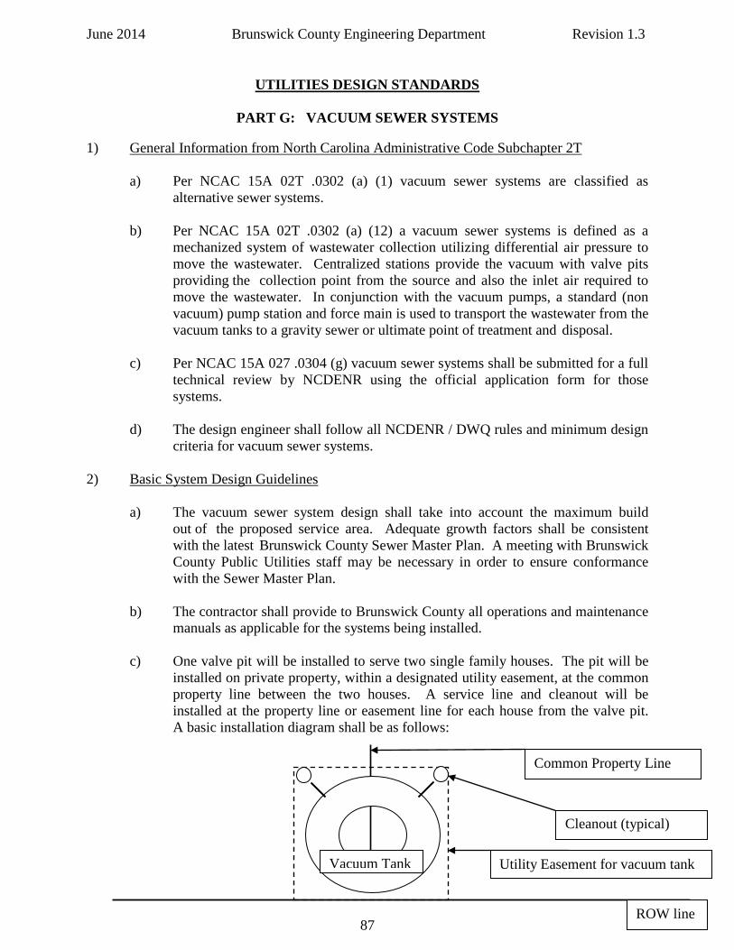
June 2014 Brunswick County Engineering Department Revision 1.3
UTILITIES DESIGN STANDARDS
PART G: VACUUM SEWER SYSTEMS
1) General Information from North Carolina Administrative Code Subchapter 2T
a) Per NCAC 15A 02T .0302 (a) (1) vacuum sewer systems are classified as alternative sewer systems.
b) Per NCAC 15A 02T .0302 (a) (12) a vacuum sewer systems is defined as a
mechanized system of wastewater collection utilizing differential air pressure to move the wastewater. Centralized stations provide the vacuum with valve pits providing the collection point from the source and also the inlet air required to move the wastewater. In conjunction with the vacuum pumps, a standard (non vacuum) pump station and force main is used to transport the wastewater from the vacuum tanks to a gravity sewer or ultimate point of treatment and disposal.
c) Per NCAC 15A 027 .0304 (g) vacuum sewer systems shall be submitted for a full
technical review by NCDENR using the official application form for those systems.
d) The design engineer shall follow all NCDENR / DWQ rules and minimum design
criteria for vacuum sewer systems. 2) Basic System Design Guidelines a) The vacuum sewer system design shall take into account the maximum build
out of the proposed service area. Adequate growth factors shall be consistent with the latest Brunswick County Sewer Master Plan. A meeting with Brunswick County Public Utilities staff may be necessary in order to ensure conformance with the Sewer Master Plan.
b) The contractor shall provide to Brunswick County all operations and maintenance
manuals as applicable for the systems being installed.
c) One valve pit will be installed to serve two single family houses. The pit will be installed on private property, within a designated utility easement, at the common property line between the two houses. A service line and cleanout will be installed at the property line or easement line for each house from the valve pit. A basic installation diagram shall be as follows:
ROW line
Common Property Line
Utility Easement for vacuum tank Vacuum Tank
Cleanout (typical)
87
June 2014 Brunswick County Engineering Department Revision 1.3
d) The standard valve pit has a maximum service capacity equivalent to twelve (12) bedrooms. A single family house cannot use more than one-half (1/2) of the pit capacity.
e) If a single family house needs more than one-half (1/2) the valve pit capacity,
based upon the number of bedrooms in the house, that house will require its own valve pit.
f) Large volume users such as schools, apartments, nursing homes, and single family
houses with more than twelve (12) bedrooms require a buffer tank instead of the standard valve pit. Buffer tanks are designed with a small operating sump in the lower portion, with additional emergency storage available in the tank.
g) Developer installed vacuum sewer systems – the developer will install the valve
pit and provide the vacuum interface valve to the county for future installation. h) For multi-family installations no more than twelve (12) bedrooms to a single
valve pit with a maximum of four (4) units to a single valve pit. i) Long runs of vacuum main without valve pits are not recommended. The lack of
valve pits, which act as energy inputs to the system to move the waste, could have a detrimental effect on system hydraulics.
j) The engineer shall design the system per AIRVAC design guidelines and provide
a statement from AIRVAC that the proposed system layout has been reviewed and approved by AIRVAC.
k) Valves shall be installed at all vacuum main intersections with sewer valve
markers per county standard detail. l) Separation requirements for water and sewer mains:
a) Horizontal and Vertical Separation
1) Minimum horizontal separation between water mains and sanitary sewer shall be ten (10) feet. The distance shall be measured edge of pipe to edge of pipe.
2) Should ten (10) foot separation not be feasible, then the water main
may be located closer to the sewer main provided that:
a) It is laid in a separate trench, b) It is laid in the same trench with the water main located at
one side on a bench of undistributed earth, c) In either of the above cases, crown elevation of the sewer
shall be at least eighteen (18) inches below invert elevation of the water line.
88
June 2014 Brunswick County Engineering Department Revision 1.3
3) Sewers crossing water mains shall be laid to provide a minimum vertical separation of eighteen (18) inches between the invert of the water main and the crown elevation of the sewer main. The crossing shall be arranged perpendicularly so that the sewer main joints will be equidistant and at least ten (10) feet from the crossing in each direction.
4) If it is impossible to maintain the required horizontal and vertical
separation as described above or anytime sewer must be laid above a water main then both the water main and sewer main must be constructed of pressure class 350 ductile iron pipe with watertight joints and pressure tested to (150) psi to assure water tightness before backfilling. At the discretion of Brunswick County a ferrous sleeve may be installed around existing water mains and force mains to meet this requirement provided DENR approval for the ferrous sleeve is first obtained by the Engineer.
5) Mechanical joints will be required for the transition in the sewer
main at water main / sewer main crossings. Fernco couplings are not permitted to be used. Special structural support for the water and sewer mains may be required.
3) Basic System Construction Guidelines
a) Typical vacuum piping network sizes are 4, 6, 8, and 10-inch pipes which connect the individual valve pits to the collection tank at the vacuum station.
b) Vacuum system piping shall be a PVC thermoplastic SDR-21 pipe conforming to
ASTM D-2241 and shall be green in color for sewer. c) Tee fittings and (90) degree bends shall not be used for vacuum sewers. Bends
are restricted to (45) degree ells only. Service laterals from the main shall utilize a wye fitting and never a tee fitting.
d) Solvent weld fittings shall be PVC schedule 40 per ASTM D-2466 from a PVC
compound having a cell classification of 12454 conforming to ASTM D-1784. e) Gasketed joint fittings shall be IPS diameter fabricated from SDR-21 PVC pipe
per ASTM D-2241 and shall be the “Rieber Style”, or approved equal, per ASTM D-3139.
f) The engineer shall verify that all fittings and mains are suitable for use in a
vacuum sewer system. g) Vacuum system mains shall be designed and constructed in a sawtooth profile per
AIRVAC specifications and as shown:
89
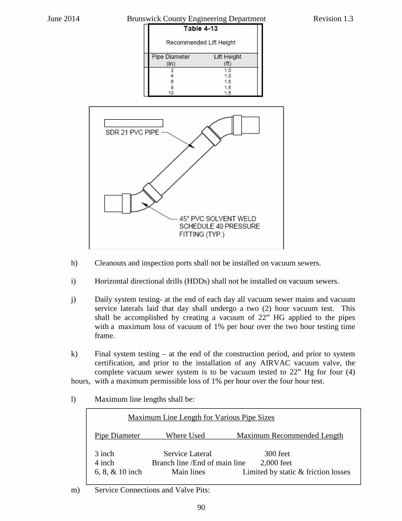
June 2014 Brunswick County Engineering Department Revision 1.3
h) Cleanouts and inspection ports shall not be installed on vacuum sewers. i) Horizontal directional drills (HDDs) shall not be installed on vacuum sewers. j) Daily system testing- at the end of each day all vacuum sewer mains and vacuum
service laterals laid that day shall undergo a two (2) hour vacuum test. This shall be accomplished by creating a vacuum of 22” HG applied to the pipes with a maximum loss of vacuum of 1% per hour over the two hour testing time frame.
k) Final system testing – at the end of the construction period, and prior to system
certification, and prior to the installation of any AIRVAC vacuum valve, the complete vacuum sewer system is to be vacuum tested to 22” Hg for four (4) hours, with a maximum permissible loss of 1% per hour over the four hour test.
l) Maximum line lengths shall be:
Maximum Line Length for Various Pipe Sizes
Pipe Diameter Where Used Maximum Recommended Length 3 inch Service Lateral 300 feet 4 inch Branch line /End of main line 2,000 feet 6, 8, & 10 inch Main lines Limited by static & friction losses
m) Service Connections and Valve Pits:
90
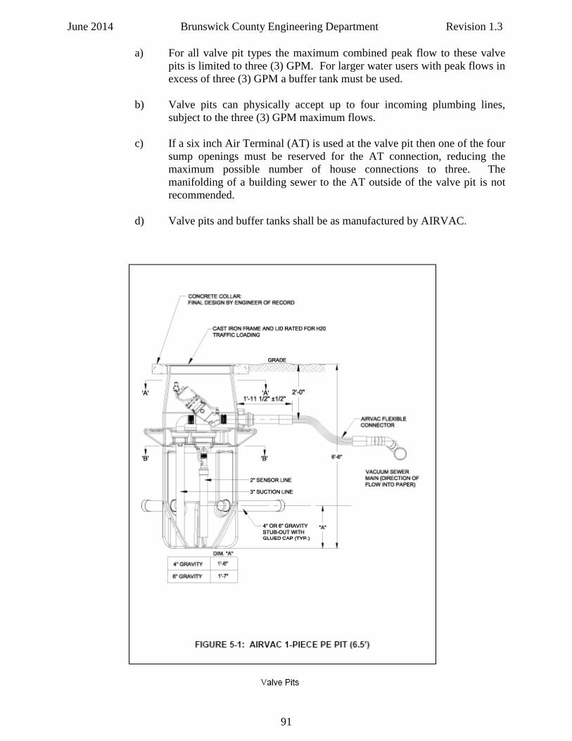
June 2014 Brunswick County Engineering Department Revision 1.3
a) For all valve pit types the maximum combined peak flow to these valve pits is limited to three (3) GPM. For larger water users with peak flows in excess of three (3) GPM a buffer tank must be used.
b) Valve pits can physically accept up to four incoming plumbing lines,
subject to the three (3) GPM maximum flows.
c) If a six inch Air Terminal (AT) is used at the valve pit then one of the four sump openings must be reserved for the AT connection, reducing the maximum possible number of house connections to three. The manifolding of a building sewer to the AT outside of the valve pit is not recommended.
d) Valve pits and buffer tanks shall be as manufactured by AIRVAC.
91
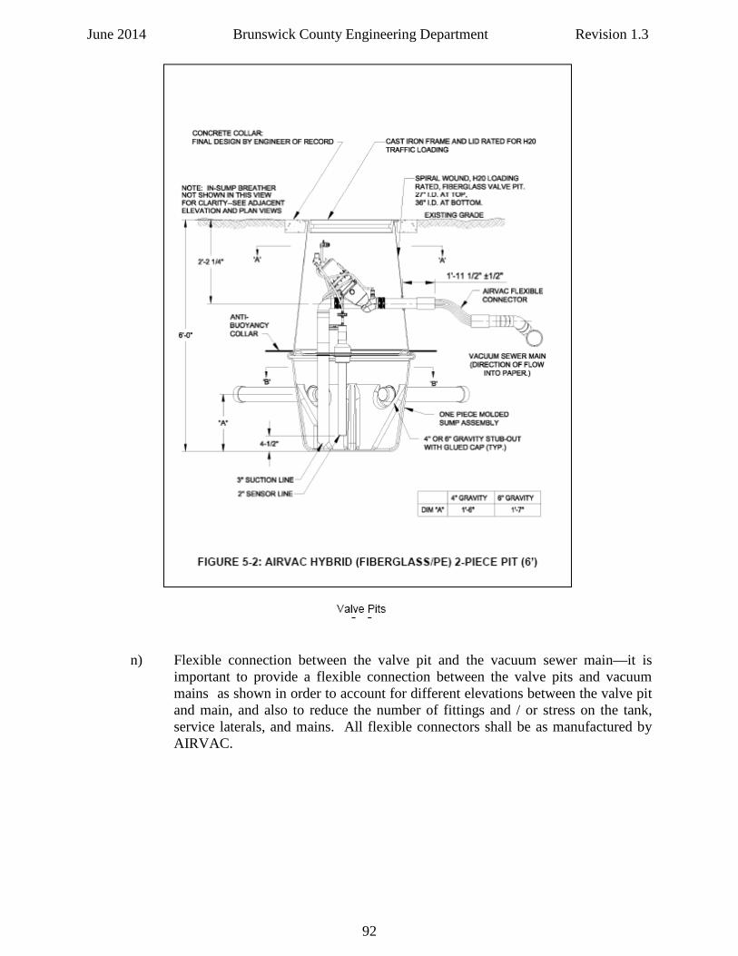
June 2014 Brunswick County Engineering Department Revision 1.3
n) Flexible connection between the valve pit and the vacuum sewer main—it is important to provide a flexible connection between the valve pits and vacuum mains as shown in order to account for different elevations between the valve pit and main, and also to reduce the number of fittings and / or stress on the tank, service laterals, and mains. All flexible connectors shall be as manufactured by AIRVAC.
92
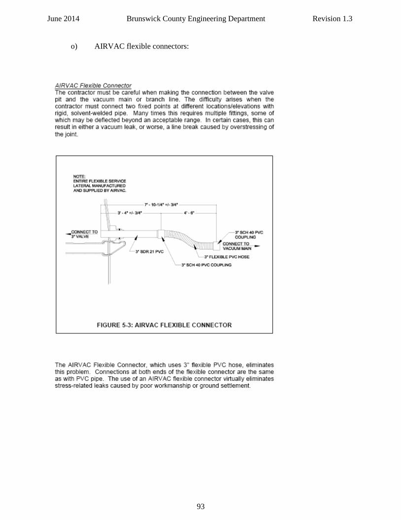
June 2014 Brunswick County Engineering Department Revision 1.3 o) AIRVAC flexible connectors:
93
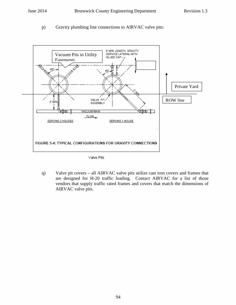
June 2014 Brunswick County Engineering Department Revision 1.3 p) Gravity plumbing line connections to AIRVAC valve pits:
q) Valve pit covers – all AIRVAC valve pits utilize cast iron covers and frames that are designed for H-20 traffic loading. Contact AIRVAC for a list of those vendors that supply traffic rated frames and covers that match the dimensions of AIRVAC valve pits.
ROW line
Private Yard
Vacuum Pits in Utility Easements
94
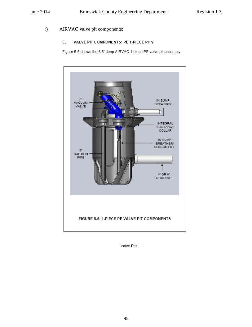
June 2014 Brunswick County Engineering Department Revision 1.3 r) AIRVAC valve pit components:
95
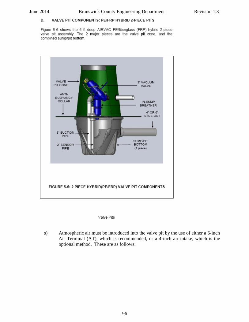
June 2014 Brunswick County Engineering Department Revision 1.3
s) Atmospheric air must be introduced into the valve pit by the use of either a 6-inch
Air Terminal (AT), which is recommended, or a 4-inch air intake, which is the optional method. These are as follows:
96
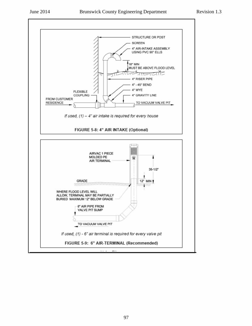
June 2014 Brunswick County Engineering Department Revision 1.3
97
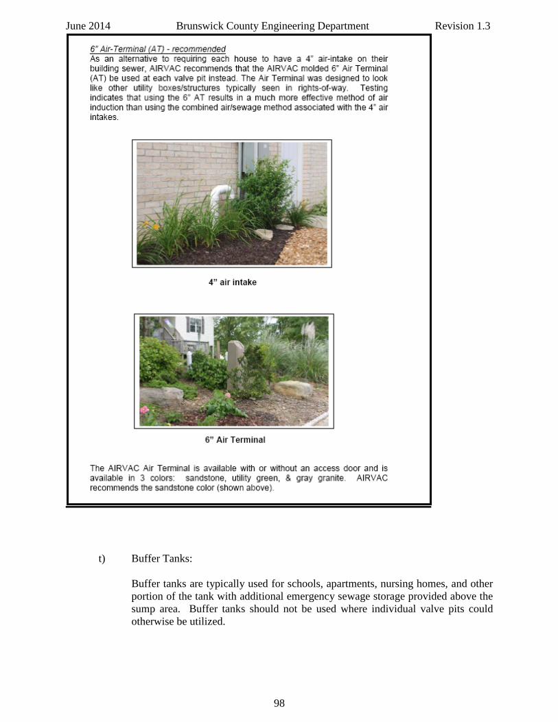
June 2014 Brunswick County Engineering Department Revision 1.3
t) Buffer Tanks:
Buffer tanks are typically used for schools, apartments, nursing homes, and other portion of the tank with additional emergency sewage storage provided above the sump area. Buffer tanks should not be used where individual valve pits could otherwise be utilized.
98
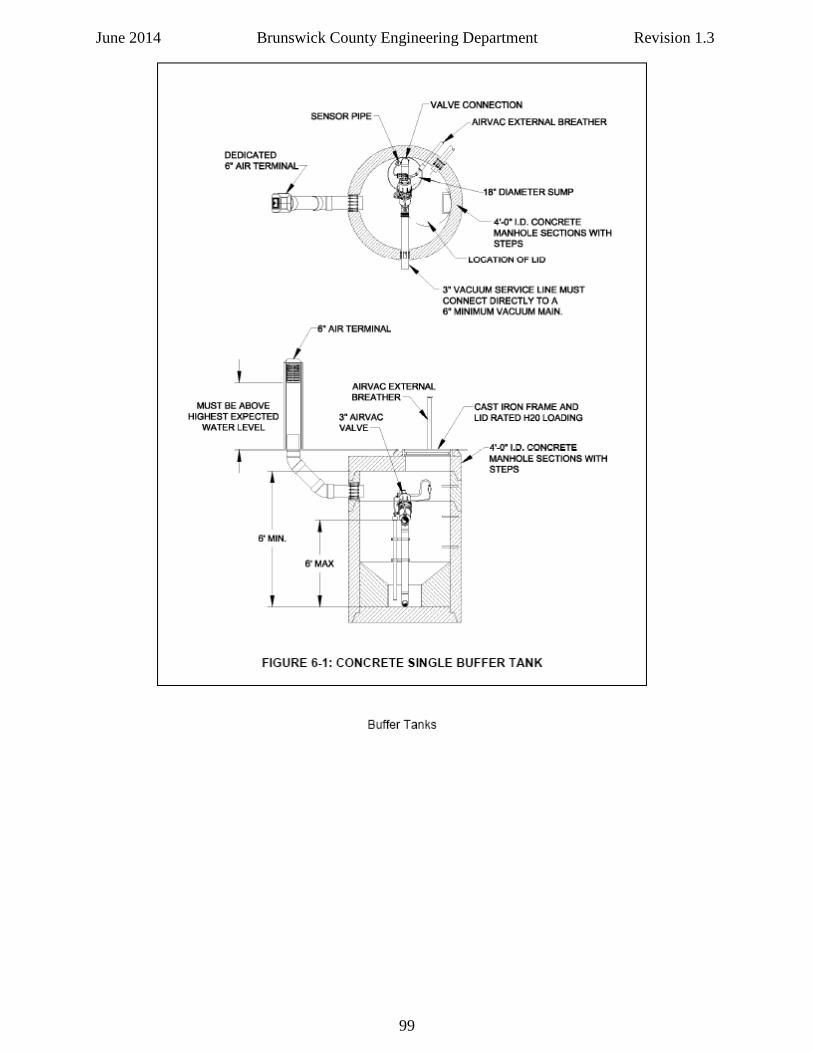
June 2014 Brunswick County Engineering Department Revision 1.3
99
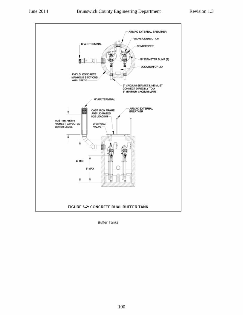
June 2014 Brunswick County Engineering Department Revision 1.3
100
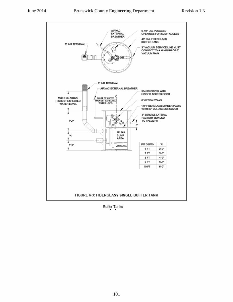
June 2014 Brunswick County Engineering Department Revision 1.3
101
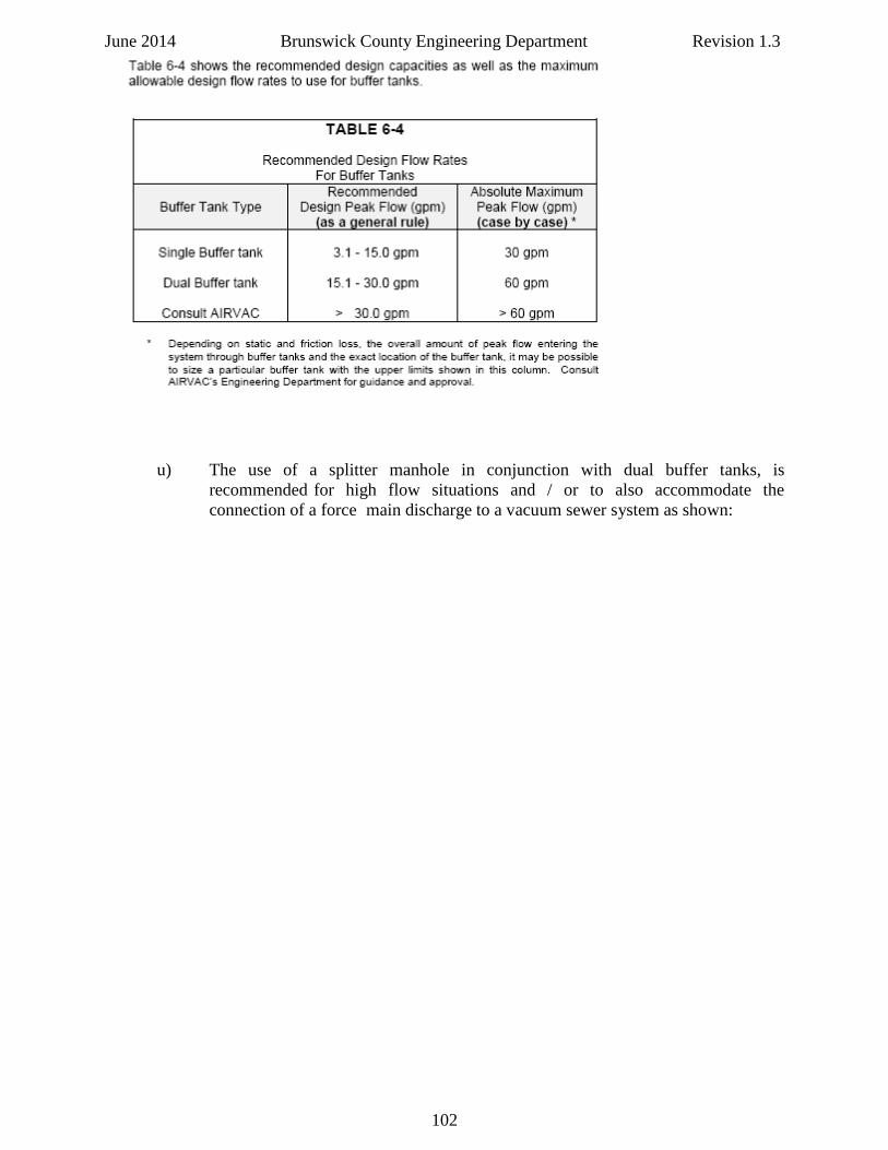
June 2014 Brunswick County Engineering Department Revision 1.3
u) The use of a splitter manhole in conjunction with dual buffer tanks, is recommended for high flow situations and / or to also accommodate the connection of a force main discharge to a vacuum sewer system as shown:
102
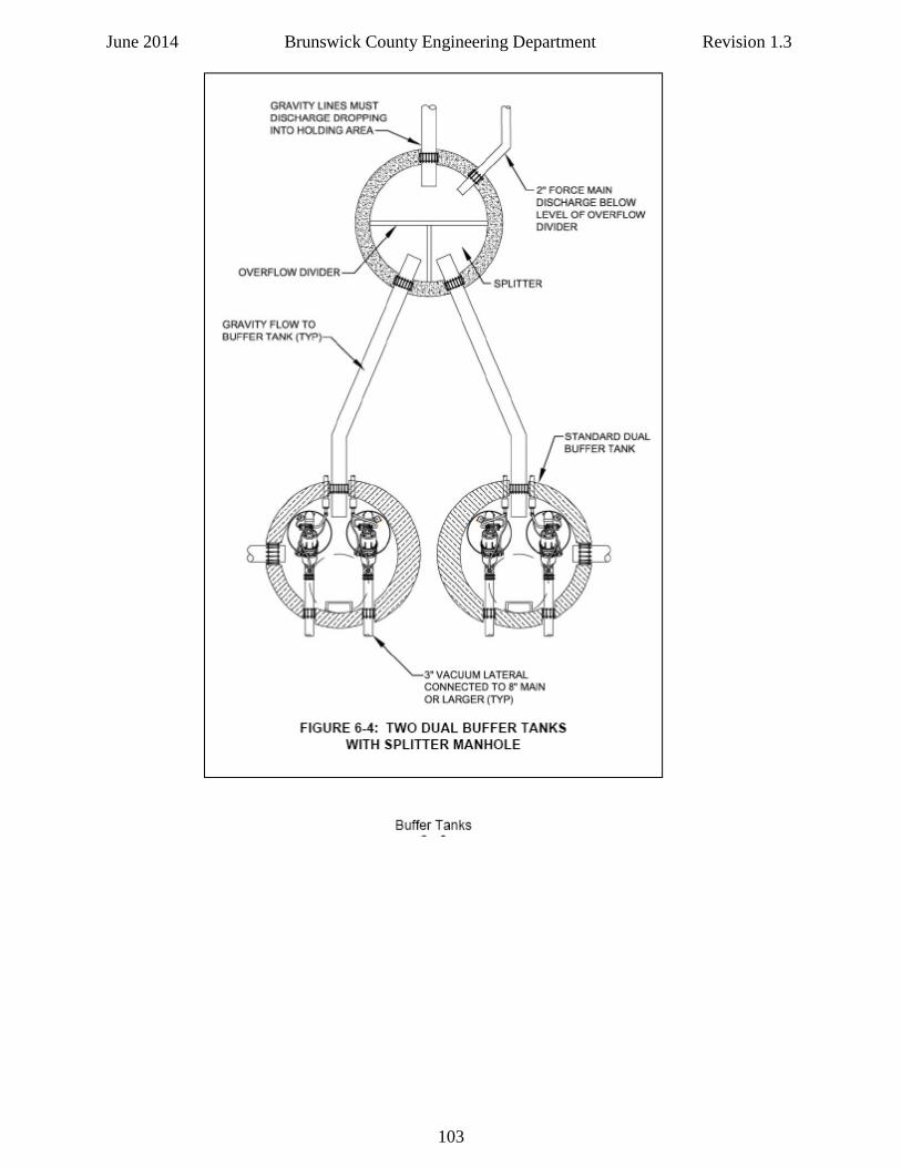
June 2014 Brunswick County Engineering Department Revision 1.3
103
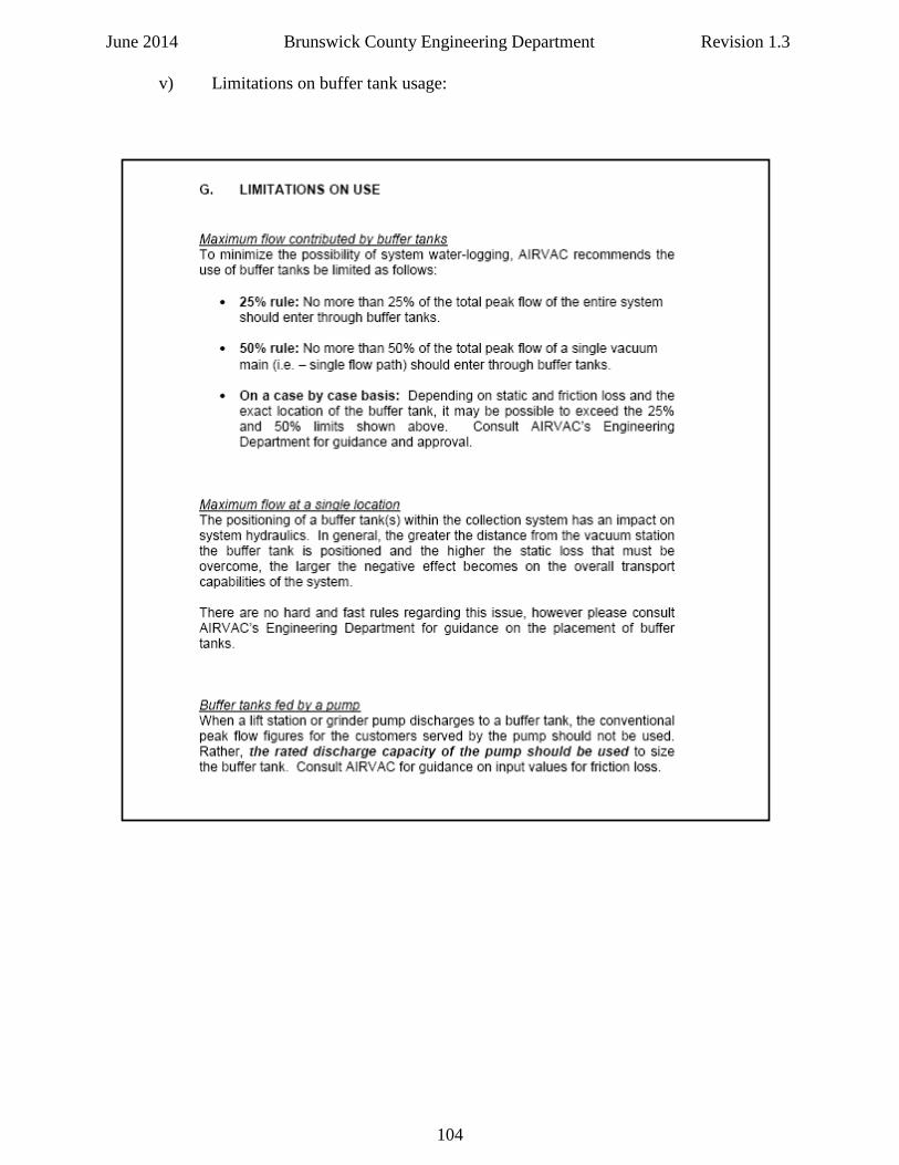
June 2014 Brunswick County Engineering Department Revision 1.3 v) Limitations on buffer tank usage:
104

June 2014 Brunswick County Engineering Department Revision 1.3
This page intentionally left blank
105