Embed Size (px)
Citation preview
5D-1ENGINEERING PRINCIPLES AND PRACTICES for Retrofitting Flood-Prone Residential Structures
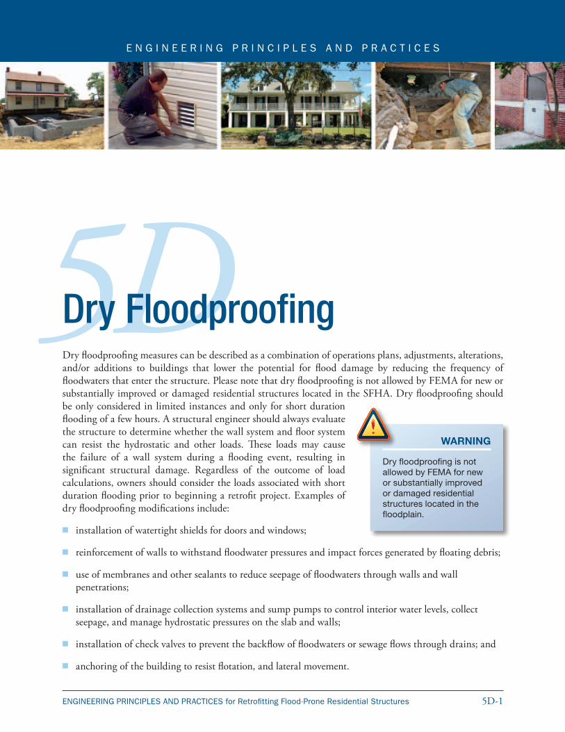
E N G I N E E R I N G P R I N C I P L E S A N D P R A C T I C E S
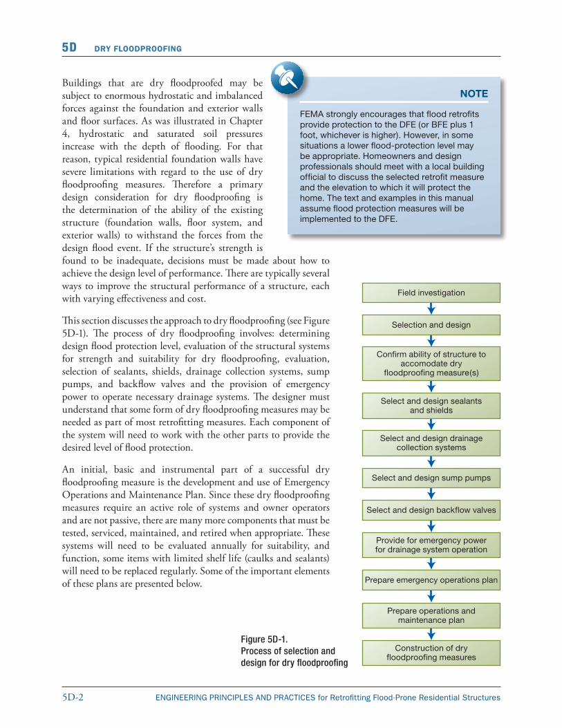
5DDry FloodproofingDry floodproofing measures can be described as a combination of operations plans, adjustments, alterations, and/or additions to buildings that lower the potential for flood damage by reducing the frequency of floodwaters that enter the structure. Please note that dry floodproofing is not allowed by FEMA for new or substantially improved or damaged residential structures located in the SFHA. Dry floodproofing should be only considered in limited instances and only for short duration flooding of a few hours. A structural engineer should always evaluate the structure to determine whether the wall system and floor system can resist the hydrostatic and other loads. These loads may cause the failure of a wall system during a flooding event, resulting in significant structural damage. Regardless of the outcome of load calculations, owners should consider the loads associated with short duration flooding prior to beginning a retrofit project. Examples of dry floodproofing modifications include:
� installation of watertight shields for doors and windows;
� reinforcement of walls to withstand floodwater pressures and impact forces generated by floating debris;
� use of membranes and other sealants to reduce seepage of floodwaters through walls and wall penetrations;
� installation of drainage collection systems and sump pumps to control interior water levels, collect seepage, and manage hydrostatic pressures on the slab and walls;
� installation of check valves to prevent the backflow of floodwaters or sewage flows through drains; and
� anchoring of the building to resist flotation, and lateral movement.
WARNING
Dry floodproofing is not allowed by FEMA for new or substantially improved or damaged residential structures located in the floodplain.
5D-2 ENGINEERING PRINCIPLES AND PRACTICES for Retrofitting Flood-Prone Residential Structures
5D DRY FLOODPROOFING
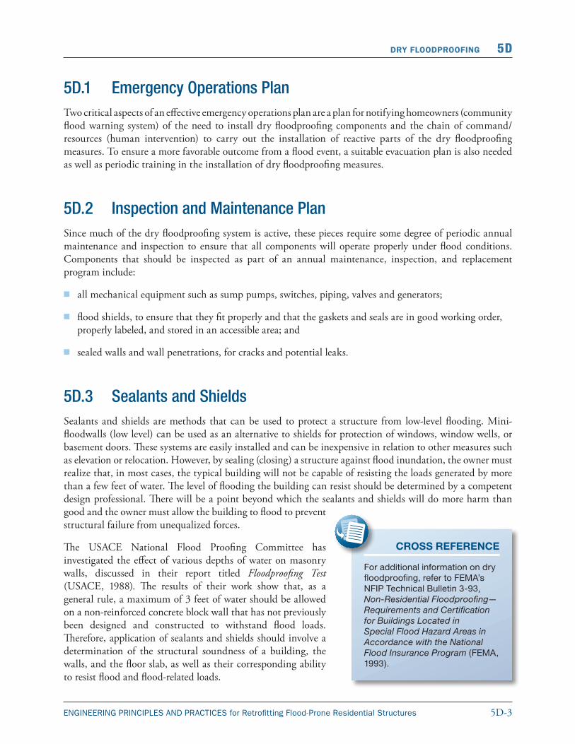
Buildings that are dry floodproofed may be subject to enormous hydrostatic and imbalanced forces against the foundation and exterior walls and floor surfaces. As was illustrated in Chapter 4, hydrostatic and saturated soil pressures increase with the depth of flooding. For that reason, typical residential foundation walls have severe limitations with regard to the use of dry floodproofing measures. Therefore a primary design consideration for dry floodproofing is the determination of the ability of the existing structure (foundation walls, floor system, and exterior walls) to withstand the forces from the design flood event. If the structure’s strength is found to be inadequate, decisions must be made about how to achieve the design level of performance. There are typically several ways to improve the structural performance of a structure, each with varying effectiveness and cost.
This section discusses the approach to dry floodproofing (see Figure 5D-1). The process of dry floodproofing involves: determining design flood protection level, evaluation of the structural systems for strength and suitability for dry floodproofing, evaluation, selection of sealants, shields, drainage collection systems, sump pumps, and backflow valves and the provision of emergency power to operate necessary drainage systems. The designer must understand that some form of dry floodproofing measures may be needed as part of most retrofitting measures. Each component of the system will need to work with the other parts to provide the desired level of flood protection.
An initial, basic and instrumental part of a successful dry floodproofing measure is the development and use of Emergency Operations and Maintenance Plan. Since these dry floodproofing measures require an active role of systems and owner operators and are not passive, there are many more components that must be tested, serviced, maintained, and retired when appropriate. These systems will need to be evaluated annually for suitability, and function, some items with limited shelf life (caulks and sealants) will need to be replaced regularly. Some of the important elements of these plans are presented below.
NOTE
FEMA strongly encourages that flood retrofits provide protection to the DFE (or BFE plus 1 foot, whichever is higher). However, in some situations a lower flood-protection level may be appropriate. Homeowners and design professionals should meet with a local building official to discuss the selected retrofit measure and the elevation to which it will protect the home. The text and examples in this manual assume flood protection measures will be implemented to the DFE.
Figure 5D-1.Process of selection and design for dry floodproofing
5D-3ENGINEERING PRINCIPLES AND PRACTICES for Retrofitting Flood-Prone Residential Structures
DRY FLOODPROOFING 5D
5D.1 Emergency Operations PlanTwo critical aspects of an effective emergency operations plan are a plan for notifying homeowners (community flood warning system) of the need to install dry floodproofing components and the chain of command/resources (human intervention) to carry out the installation of reactive parts of the dry floodproofing measures. To ensure a more favorable outcome from a flood event, a suitable evacuation plan is also needed as well as periodic training in the installation of dry floodproofing measures.
5D.2 Inspection and Maintenance PlanSince much of the dry floodproofing system is active, these pieces require some degree of periodic annual maintenance and inspection to ensure that all components will operate properly under flood conditions. Components that should be inspected as part of an annual maintenance, inspection, and replacement program include:
� all mechanical equipment such as sump pumps, switches, piping, valves and generators;
� flood shields, to ensure that they fit properly and that the gaskets and seals are in good working order, properly labeled, and stored in an accessible area; and
� sealed walls and wall penetrations, for cracks and potential leaks.
5D.3 Sealants and ShieldsSealants and shields are methods that can be used to protect a structure from low-level flooding. Mini-floodwalls (low level) can be used as an alternative to shields for protection of windows, window wells, or basement doors. These systems are easily installed and can be inexpensive in relation to other measures such as elevation or relocation. However, by sealing (closing) a structure against flood inundation, the owner must realize that, in most cases, the typical building will not be capable of resisting the loads generated by more than a few feet of water. The level of flooding the building can resist should be determined by a competent design professional. There will be a point beyond which the sealants and shields will do more harm than good and the owner must allow the building to flood to prevent structural failure from unequalized forces.
The USACE National Flood Proofing Committee has investigated the effect of various depths of water on masonry walls, discussed in their report titled Floodproofing Test (USACE, 1988). The results of their work show that, as a general rule, a maximum of 3 feet of water should be allowed on a non-reinforced concrete block wall that has not previously been designed and constructed to withstand flood loads. Therefore, application of sealants and shields should involve a determination of the structural soundness of a building, the walls, and the floor slab, as well as their corresponding ability to resist flood and flood-related loads.
CROSS REFERENCE
For additional information on dry floodproofing, refer to FEMA’s NFIP Technical Bulletin 3-93, Non-Residential Floodproofing—Requirements and Certification for Buildings Located in Special Flood Hazard Areas in Accordance with the National Flood Insurance Program (FEMA, 1993).
5D-4 ENGINEERING PRINCIPLES AND PRACTICES for Retrofitting Flood-Prone Residential Structures
5D DRY FLOODPROOFING
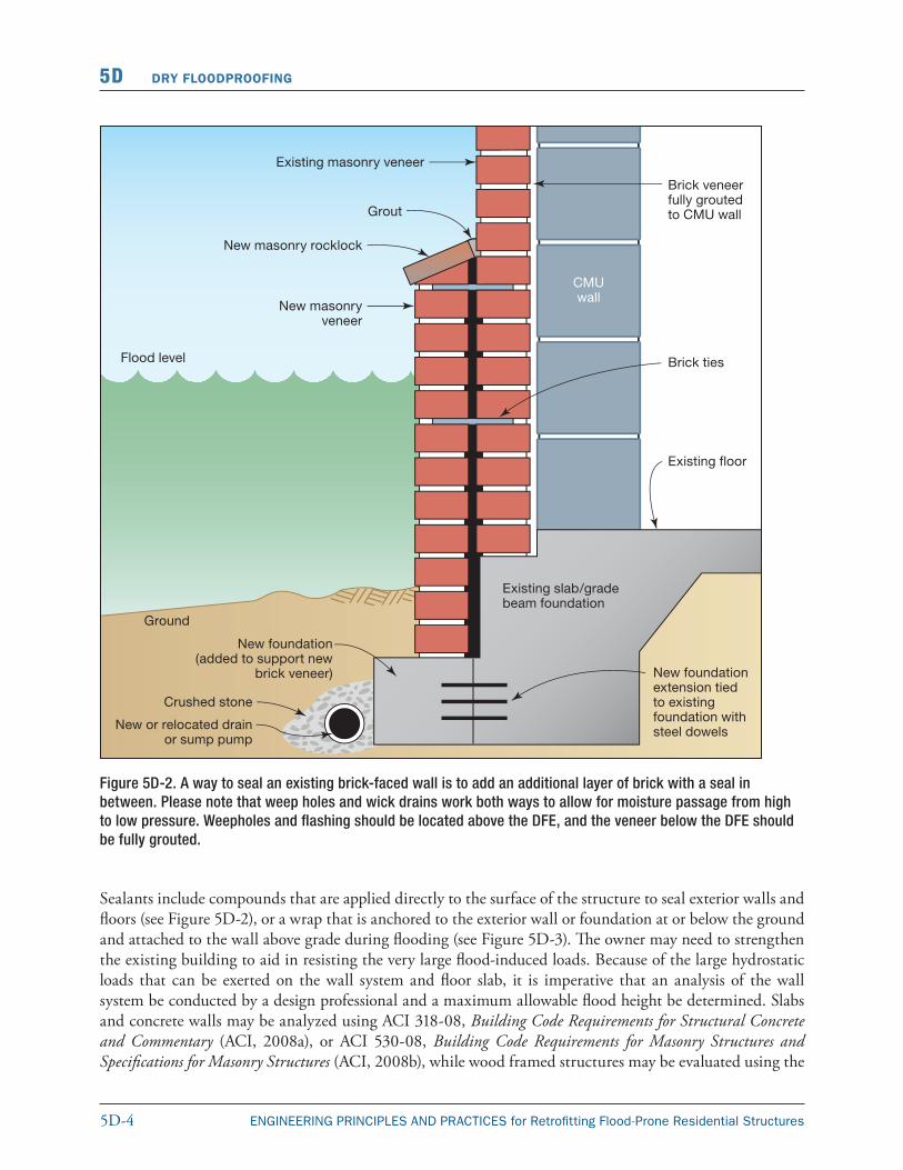
Sealants include compounds that are applied directly to the surface of the structure to seal exterior walls and floors (see Figure 5D-2), or a wrap that is anchored to the exterior wall or foundation at or below the ground and attached to the wall above grade during flooding (see Figure 5D-3). The owner may need to strengthen the existing building to aid in resisting the very large flood-induced loads. Because of the large hydrostatic loads that can be exerted on the wall system and floor slab, it is imperative that an analysis of the wall system be conducted by a design professional and a maximum allowable flood height be determined. Slabs and concrete walls may be analyzed using ACI 318-08, Building Code Requirements for Structural Concrete and Commentary (ACI, 2008a), or ACI 530-08, Building Code Requirements for Masonry Structures and Specifications for Masonry Structures (ACI, 2008b), while wood framed structures may be evaluated using the
Figure 5D-2. A way to seal an existing brick-faced wall is to add an additional layer of brick with a seal in between. Please note that weep holes and wick drains work both ways to allow for moisture passage from high to low pressure. Weepholes and flashing should be located above the DFE, and the veneer below the DFE should be fully grouted.
5D-5ENGINEERING PRINCIPLES AND PRACTICES for Retrofitting Flood-Prone Residential Structures
DRY FLOODPROOFING 5D
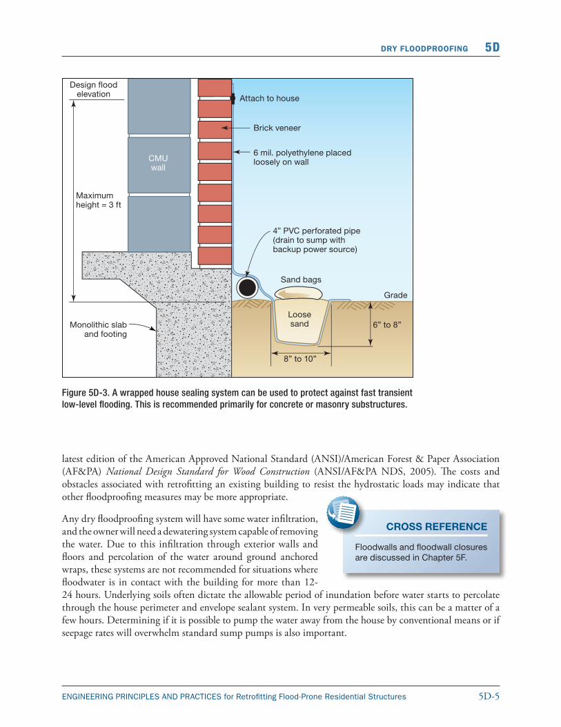
Figure 5D-3. A wrapped house sealing system can be used to protect against fast transient low-level flooding. This is recommended primarily for concrete or masonry substructures.
latest edition of the American Approved National Standard (ANSI)/American Forest & Paper Association (AF&PA) National Design Standard for Wood Construction (ANSI/AF&PA NDS, 2005). The costs and obstacles associated with retrofitting an existing building to resist the hydrostatic loads may indicate that other floodproofing measures may be more appropriate.
Any dry floodproofing system will have some water infiltration, and the owner will need a dewatering system capable of removing the water. Due to this infiltration through exterior walls and floors and percolation of the water around ground anchored wraps, these systems are not recommended for situations where floodwater is in contact with the building for more than 12-24 hours. Underlying soils often dictate the allowable period of inundation before water starts to percolate through the house perimeter and envelope sealant system. In very permeable soils, this can be a matter of a few hours. Determining if it is possible to pump the water away from the house by conventional means or if seepage rates will overwhelm standard sump pumps is also important.
CROSS REFERENCE
Floodwalls and floodwall closures are discussed in Chapter 5F.
5D-6 ENGINEERING PRINCIPLES AND PRACTICES for Retrofitting Flood-Prone Residential Structures
5D DRY FLOODPROOFING
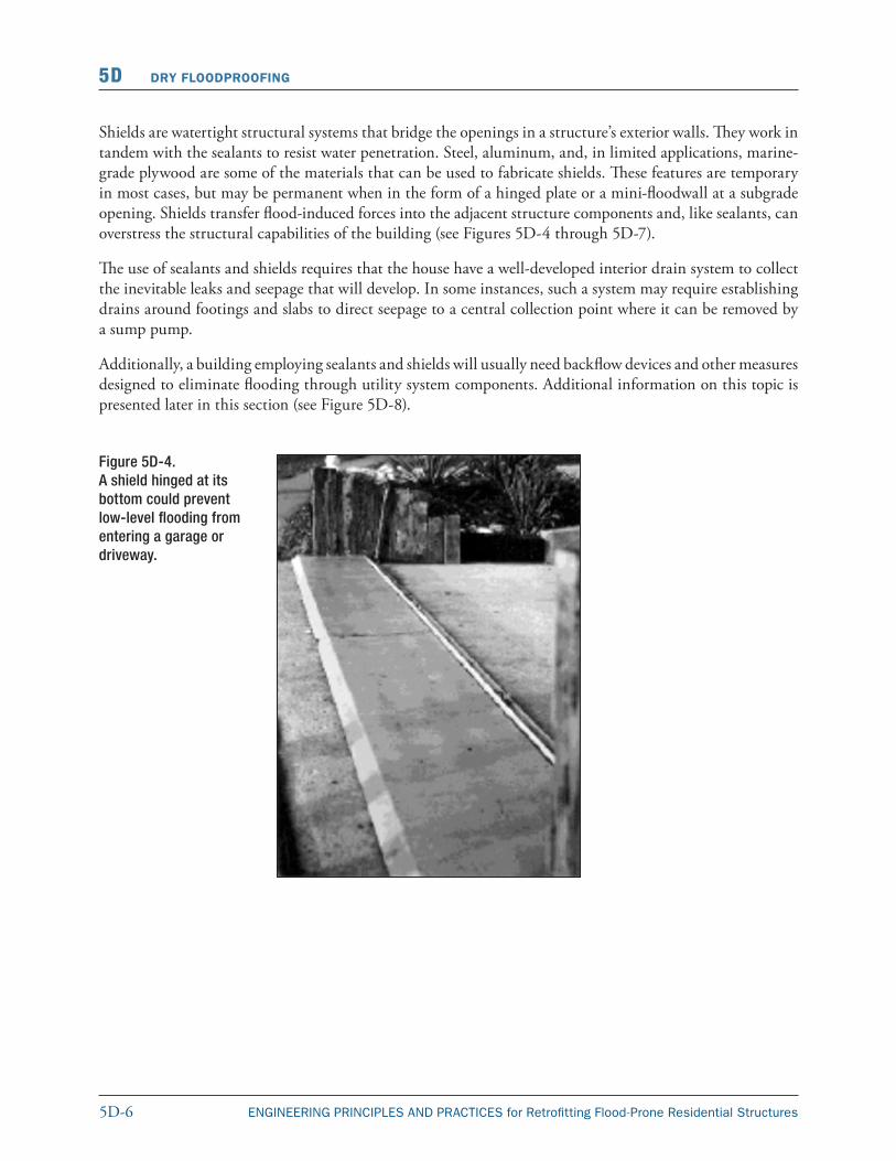
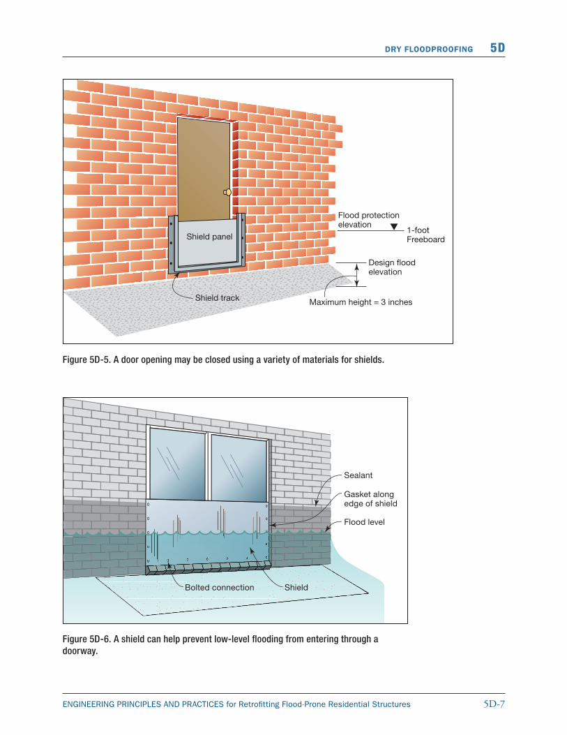
Shields are watertight structural systems that bridge the openings in a structure’s exterior walls. They work in tandem with the sealants to resist water penetration. Steel, aluminum, and, in limited applications, marine-grade plywood are some of the materials that can be used to fabricate shields. These features are temporary in most cases, but may be permanent when in the form of a hinged plate or a mini-floodwall at a subgrade open ing. Shields transfer flood-induced forces into the adjacent structure components and, like sealants, can overstress the structural capabilities of the building (see Figures 5D-4 through 5D-7).
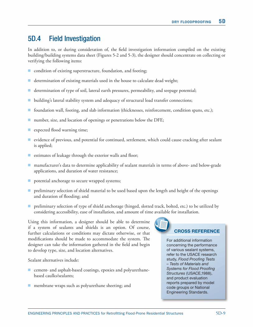
The use of sealants and shields requires that the house have a well-developed interior drain system to collect the inevitable leaks and seepage that will develop. In some instances, such a system may require establishing drains around footings and slabs to direct seepage to a central collection point where it can be removed by a sump pump.
Additionally, a building employing sealants and shields will usually need backflow devices and other measures designed to eliminate flooding through utility system components. Additional information on this topic is presented later in this section (see Figure 5D-8).
Figure 5D-4. A shield hinged at its bottom could prevent low-level flooding from entering a garage or driveway.
5D-7ENGINEERING PRINCIPLES AND PRACTICES for Retrofitting Flood-Prone Residential Structures
DRY FLOODPROOFING 5D
Figure 5D-5. A door opening may be closed using a variety of materials for shields.
Figure 5D-6. A shield can help prevent low-level flooding from entering through a doorway.
5D-8 ENGINEERING PRINCIPLES AND PRACTICES for Retrofitting Flood-Prone Residential Structures
5D DRY FLOODPROOFING
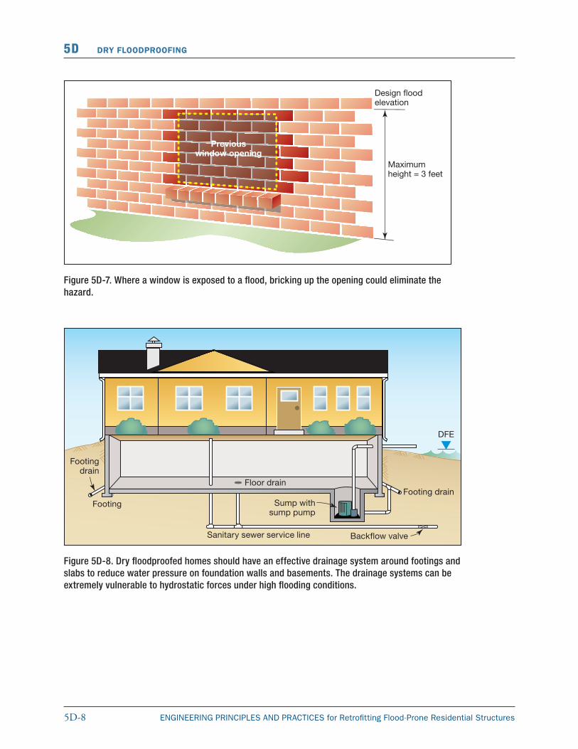
Figure 5D-7. Where a window is exposed to a flood, bricking up the opening could eliminate the hazard.
Figure 5D-8. Dry floodproofed homes should have an effective drainage system around footings and slabs to reduce water pressure on foundation walls and basements. The drainage systems can be extremely vulnerable to hydrostatic forces under high flooding conditions.
5D-9ENGINEERING PRINCIPLES AND PRACTICES for Retrofitting Flood-Prone Residential Structures
DRY FLOODPROOFING 5D
5D.4 Field InvestigationIn addition to, or during consideration of, the field investigation information compiled on the existing building/building systems data sheet (Figures 5-2 and 5-3), the designer should concentrate on collecting or verifying the following items:
� condition of existing superstructure, foundation, and footing;
� determination of existing materials used in the house to calculate dead weight;
� determination of type of soil, lateral earth pressures, permeability, and seepage potential;
� building’s lateral stability system and adequacy of structural load transfer connections;
� foundation wall, footing, and slab information (thicknesses, reinforcement, condition spans, etc.);
� number, size, and location of openings or penetrations below the DFE;
� expected flood warning time;
� evidence of previous, and potential for continued, settlement, which could cause cracking after sealant is applied;
� estimates of leakage through the exterior walls and floor;
� manufacturer’s data to determine applicability of sealant materials in terms of above- and below-grade applications, and duration of water resistance;
� potential anchorage to secure wrapped systems;
� preliminary selection of shield material to be used based upon the length and height of the openings and duration of flooding; and
� preliminary selection of type of shield anchorage (hinged, slotted track, bolted, etc.) to be utilized by considering accessibility, ease of installation, and amount of time available for installation.
Using this information, a designer should be able to determine if a system of sealants and shields is an option. Of course, further calculations or conditions may dictate otherwise, or that modifications should be made to accommodate the system. The designer can take the information gathered in the field and begin to develop type, size, and location alternatives.
Sealant alternatives include:
� cement- and asphalt-based coatings, epoxies and polyurethane-based caulks/sealants;
� membrane wraps such as polyurethane sheeting; and
CROSS REFERENCE
For additional information concern ing the performance of various sealant systems, refer to the USACE research study, Flood Proofing Tests – Tests of Materials and Systems for Flood Proofing Structures (USACE,1988), and product evaluation reports prepared by model code groups or National Engineering Standards.
5D-10 ENGINEERING PRINCIPLES AND PRACTICES for Retrofitting Flood-Prone Residential Structures
5D DRY FLOODPROOFING
� brick veneers over a waterproof coating on the existing concrete or CMU block foundation; brick veneers below the DFE must be fully grouted.
Shield alternatives include:
� a permanent low wall to protect doors and window wells against low-level flooding;
� bricking in a nonessential opening with an impermeable membrane; and
� drop-in, bolted, and hinged shields that cover an opening in the existing structure.
5D.5 Confirm Structure is Designed to Accommodate Dry Floodproofing Measures
A critical step in the development of initial type, size, and location of the sealant and shield systems is to determine the ability of the existing superstructure and foundation to resist the expected flood- and non-flood-related forces. The flood forces are illustrated in Figure 5D-9 and the design process is illustrated in Figure 5D-10.
Step 1: Calculate flood and flood-related forces.
The calculation of flood and flood-related forces (hydrostatic, hydrodynamic, buoyancy, soil, and debris impact forces) as well as determination of seepage and interior drainage rates was presented in Chapter 4. The designer should account for any non-flood-related forces (i.e., wind, seismic, etc.) by incorporating those forces into Steps 2-6. The determination of non-flood related forces was presented in Chapter 4.
Step 2: Check flotation of the superstructure.
Residential structures that are determined to be watertight should be checked to ensure that the entire sub- and super-structure will not float. However, it is reasonable to assume that most residential construction will fail prior to flotation of the structure. This failure will most likely occur through the slab-on-grade breaking (heaving/cracking), a window or door failing inward, or extensive leakage through wall penetrations. Should
Figure 5D-9. Illustration of hydrostatic force
5D-11ENGINEERING PRINCIPLES AND PRACTICES for Retrofitting Flood-Prone Residential Structures
DRY FLOODPROOFING 5D
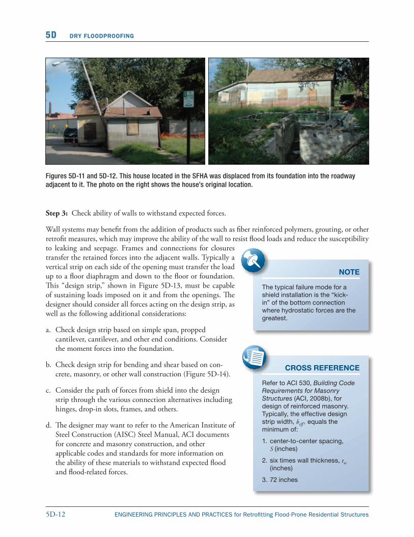
the designer wish to check the failure assumption, guidance is provided in Step 5. If floodwaters come into contact with a wood floor diaphragm (elevated floor or crawlspace home), the floor system/building super-structure should be checked for flotation (Figures 5D-11 and 5D-12).
Check the sum of the vertical hydrostatic (buoyancy) forces acting upward against the gravity forces (dead load) acting downward on the structure. The gravity forces acting downward should be greater than the buoyancy forces acting upward (Figure 5D-9). If this is not the case, the designer should consider choosing another floodproofing method or designing an anti-flotation system. The homeowner should make this decision based upon technical and cost information supplied by the designer.
Figure 5D-10. Existing building structural evaluations
5D-12 ENGINEERING PRINCIPLES AND PRACTICES for Retrofitting Flood-Prone Residential Structures
5D DRY FLOODPROOFING
Figures 5D-11 and 5D-12. This house located in the SFHA was displaced from its foundation into the roadway adjacent to it. The photo on the right shows the house’s original location.
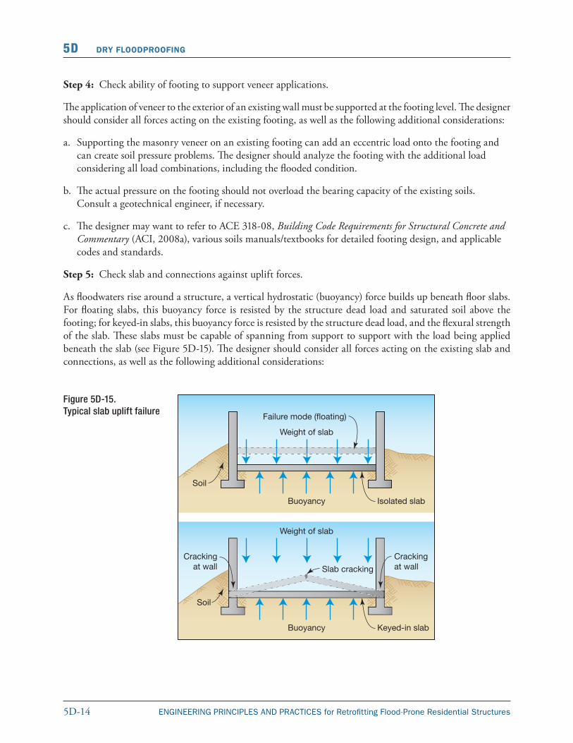
Step 3: Check ability of walls to withstand expected forces.
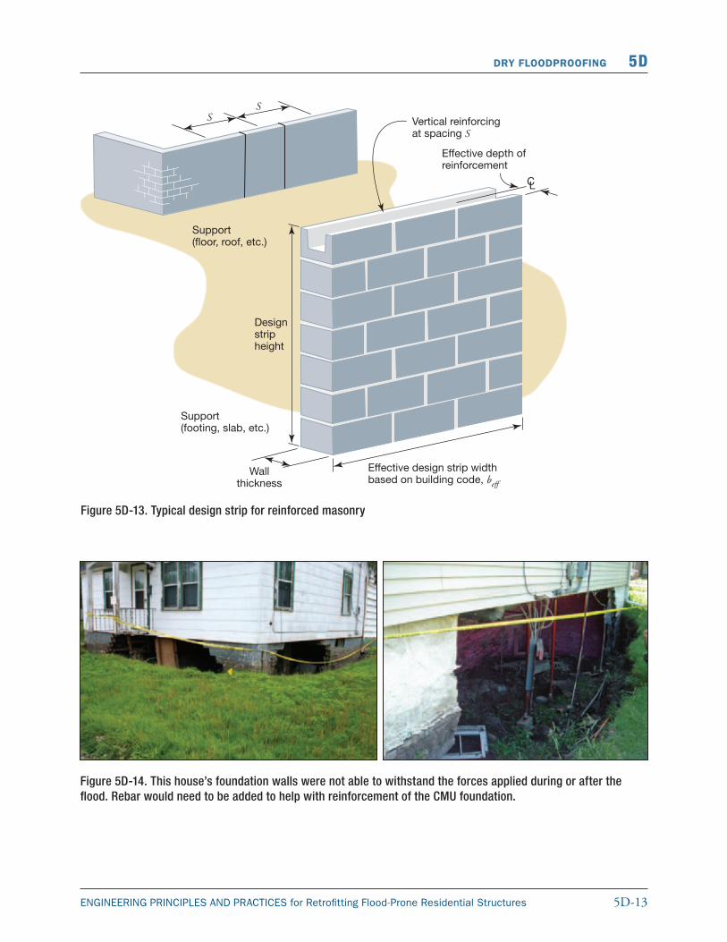
Wall systems may benefit from the addition of products such as fiber reinforced polymers, grouting, or other retrofit measures, which may improve the ability of the wall to resist flood loads and reduce the susceptibility to leaking and seepage. Frames and connections for closures transfer the retained forces into the adjacent walls. Typically a vertical strip on each side of the opening must transfer the load up to a floor diaphragm and down to the floor or foundation. This “design strip,” shown in Figure 5D-13, must be capable of sustaining loads imposed on it and from the openings. The designer should consider all forces acting on the design strip, as well as the following additional considerations:
a. Check design strip based on simple span, propped cantilever, cantilever, and other end conditions. Consider the moment forces into the foundation.
b. Check design strip for bending and shear based on con-crete, masonry, or other wall construction (Figure 5D-14).
c. Consider the path of forces from shield into the design strip through the various connection alternatives including hinges, drop-in slots, frames, and others.
d. The designer may want to refer to the American Institute of Steel Construction (AISC) Steel Manual, ACI documents for concrete and masonry construction, and other applicable codes and standards for more information on the ability of these materials to withstand expected flood and flood-related forces.
CROSS REFERENCE
Refer to ACI 530, Building Code Requirements for Masonry Structures (ACI, 2008b), for design of reinforced masonry. Typically, the effective design strip width, beff , equals the minimum of:
1. center-to-center spacing, S (inches)
2. six times wall thickness, tw (inches)
3. 72 inches
NOTE
The typical failure mode for a shield installation is the “kick-in” of the bottom connection where hydrostatic forces are the greatest.
5D-13ENGINEERING PRINCIPLES AND PRACTICES for Retrofitting Flood-Prone Residential Structures
DRY FLOODPROOFING 5D
Figure 5D-13. Typical design strip for reinforced masonry
Figure 5D-14. This house’s foundation walls were not able to withstand the forces applied during or after the flood. Rebar would need to be added to help with reinforcement of the CMU foundation.
5D-14 ENGINEERING PRINCIPLES AND PRACTICES for Retrofitting Flood-Prone Residential Structures
5D DRY FLOODPROOFING
Step 4: Check ability of footing to support veneer applications.
The application of veneer to the exterior of an existing wall must be supported at the footing level. The designer should consider all forces acting on the existing footing, as well as the following additional considerations:
a. Supporting the masonry veneer on an existing footing can add an eccentric load onto the footing and can create soil pressure problems. The designer should analyze the footing with the additional load considering all load combinations, including the flooded condition.
b. The actual pressure on the footing should not overload the bearing capacity of the existing soils. Consult a geotechnical engineer, if necessary.
c. The designer may want to refer to ACE 318-08, Building Code Requirements for Structural Concrete and Commentary (ACI, 2008a), various soils manuals/textbooks for detailed footing design, and applicable codes and standards.
Step 5: Check slab and connections against uplift forces.
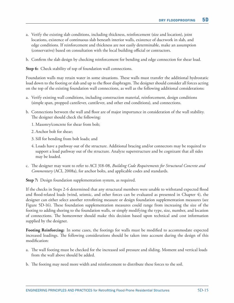
As floodwaters rise around a structure, a vertical hydrostatic (buoyancy) force builds up beneath floor slabs. For floating slabs, this buoyancy force is resisted by the structure dead load and saturated soil above the footing; for keyed-in slabs, this buoyancy force is resisted by the structure dead load, and the flexural strength of the slab. These slabs must be capable of spanning from support to support with the load being applied beneath the slab (see Figure 5D-15). The designer should consider all forces acting on the existing slab and connections, as well as the following additional considerations:
Figure 5D-15. Typical slab uplift failure
5D-15ENGINEERING PRINCIPLES AND PRACTICES for Retrofitting Flood-Prone Residential Structures
DRY FLOODPROOFING 5D
a. Verify the existing slab conditions, including thickness, reinforcement (size and location), joint locations, existence of continuous slab beneath interior walls, existence of ductwork in slab, and edge conditions. If reinforcement and thickness are not easily determinable, make an assumption (conservative) based on consultation with the local building official or contractors.
b. Confirm the slab design by checking reinforcement for bending and edge connection for shear load.
Step 6: Check stability of top of foundation wall connections.
Foundation walls may retain water in some situations. These walls must transfer the additional hydrostatic load down to the footing or slab and up to the floor diaphragm. The designer should consider all forces acting on the top of the existing foundation wall connections, as well as the following additional considerations:
a. Verify existing wall conditions, including construction material, reinforcement, design conditions (simple span, propped cantilever, cantilever, and other end conditions), and connections.
b. Connections between the wall and floor are of major importance in consideration of the wall stability. The designer should check the following:
1. Masonry/concrete for shear from bolt;
2. Anchor bolt for shear;
3. Sill for bending from bolt loads; and
4. Loads have a pathway out of the structure. Additional bracing and/or connectors may be required to support a load pathway out of the structure. Analyze superstructure and be cognizant that all sides may be loaded.
c. The designer may want to refer to ACI 318-08, Building Code Requirements for Structural Concrete and Commentary (ACI, 2008a), for anchor bolts, and applicable codes and standards.
Step 7: Design foundation supplementation system, as required.
If the checks in Steps 2-6 determined that any structural members were unable to withstand expected flood and flood-related loads (wind, seismic, and other forces can be evaluated as presented in Chapter 4), the designer can either select another retrofitting measure or design foundation supplementation measures (see Figure 5D-16). These foundation supplementation measures could range from increasing the size of the footing to adding shoring to the foundation walls, or simply modifying the type, size, number, and location of connections. The homeowner should make this decision based upon technical and cost information supplied by the designer.
Footing Reinforcing: In some cases, the footings for walls must be modified to accommodate expected increased loadings. The following considerations should be taken into account during the design of this modification:
a. The wall footing must be checked for the increased soil pressure and sliding. Moment and vertical loads from the wall above should be added.
b. The footing may need more width and reinforcement to distribute these forces to the soil.
5D-16 ENGINEERING PRINCIPLES AND PRACTICES for Retrofitting Flood-Prone Residential Structures
5D DRY FLOODPROOFING
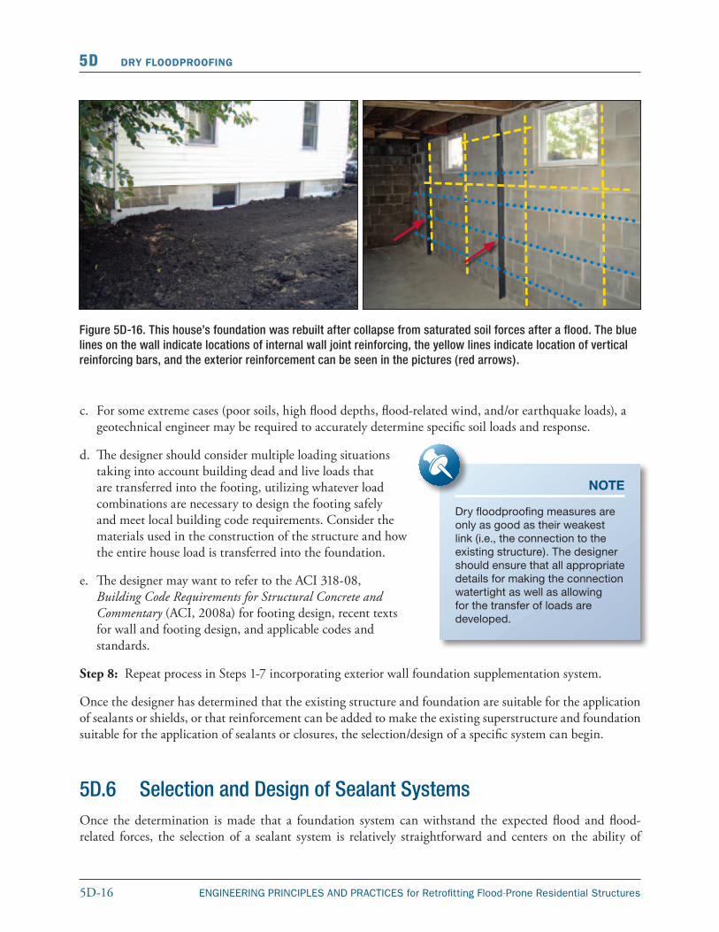
Figure 5D-16. This house’s foundation was rebuilt after collapse from saturated soil forces after a flood. The blue lines on the wall indicate locations of internal wall joint reinforcing, the yellow lines indicate location of vertical reinforcing bars, and the exterior reinforcement can be seen in the pictures (red arrows).
c. For some extreme cases (poor soils, high flood depths, flood-related wind, and/or earthquake loads), a geotechnical engineer may be required to accurately determine specific soil loads and response.
d. The designer should consider multiple loading situations taking into account building dead and live loads that are transferred into the footing, utilizing whatever load combinations are necessary to design the footing safely and meet local building code requirements. Consider the materials used in the construction of the structure and how the entire house load is transferred into the foundation.
e. The designer may want to refer to the ACI 318-08, Building Code Requirements for Structural Concrete and Commentary (ACI, 2008a) for footing design, recent texts for wall and footing design, and applicable codes and standards.
Step 8: Repeat process in Steps 1-7 incorporating exterior wall foundation supplementation system.
Once the designer has determined that the existing structure and foundation are suitable for the application of sealants or shields, or that reinforcement can be added to make the existing superstructure and foundation suitable for the application of sealants or closures, the selection/design of a specific system can begin.
NOTE
Dry floodproofing measures are only as good as their weakest link (i.e., the connection to the existing structure). The designer should en sure that all appropriate details for making the connection watertight as well as allowing for the transfer of loads are developed.
5D.6 Selection and Design of Sealant SystemsOnce the determination is made that a foundation system can withstand the expected flood and flood-related forces, the selection of a sealant system is relatively straightforward and centers on the ability of
5D-17ENGINEERING PRINCIPLES AND PRACTICES for Retrofitting Flood-Prone Residential Structures
DRY FLOODPROOFING 5D
the manufacturer’s product to be compatible with the length and depth of flooding expected and the type of construction materials used in the structure.
5D.6.1 Coatings
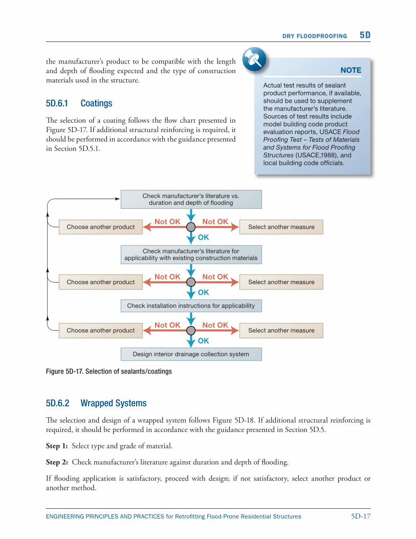
The selection of a coating follows the flow chart presented in Figure 5D-17. If additional structural reinforcing is required, it should be performed in accordance with the guidance presented in Section 5D.5.1.
NOTE
Actual test results of sealant product performance, if available, should be used to supplement the manufacturer’s literature. Sources of test results include model building code product evaluation reports, USACE Flood Proofing Test – Tests of Materials and Systems for Flood Proofing Structures (USACE,1988), and local building code officials.
Figure 5D-17. Selection of sealants/coatings
5D.6.2 Wrapped Systems
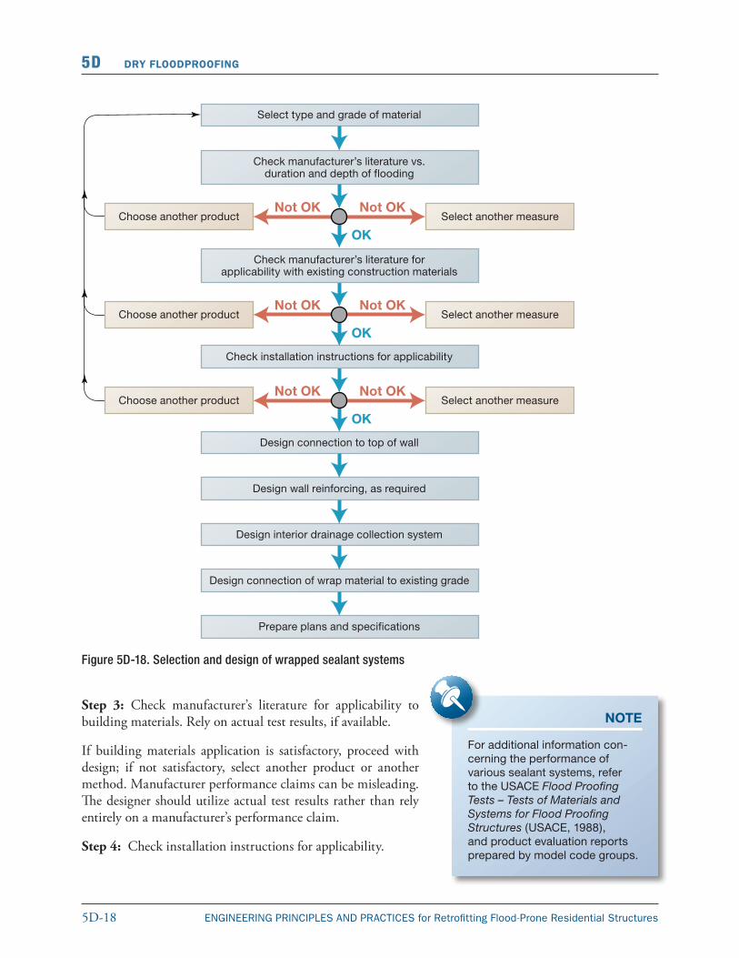
The selection and design of a wrapped system follows Figure 5D-18. If additional structural reinforcing is required, it should be performed in accordance with the guidance presented in Section 5D.5.
Step 1: Select type and grade of material.
Step 2: Check manufacturer’s literature against duration and depth of flooding.
If flooding application is satisfactory, proceed with design; if not satisfactory, select another product or another method.
5D-18 ENGINEERING PRINCIPLES AND PRACTICES for Retrofitting Flood-Prone Residential Structures
5D DRY FLOODPROOFING
Figure 5D-18. Selection and design of wrapped sealant systems
Step 3: Check manufacturer’s literature for applicability to building materials. Rely on actual test results, if available.
If building materials application is satisfactory, proceed with design; if not satisfactory, select another product or another method. Manufacturer performance claims can be misleading. The designer should utilize actual test results rather than rely entirely on a manufacturer’s performance claim.
Step 4: Check installation instructions for applicability.
NOTE
For additional information con-cerning the performance of various sealant systems, refer to the USACE Flood Proofing Tests – Tests of Materials and Systems for Flood Proofing Structures (USACE, 1988), and product evaluation reports prepared by model code groups.
5D-19ENGINEERING PRINCIPLES AND PRACTICES for Retrofitting Flood-Prone Residential Structures
DRY FLOODPROOFING 5D
If installation procedure is satisfactory, proceed with design; if not satisfactory, select another product or another method.
Step 5: Design connection to top of wall.
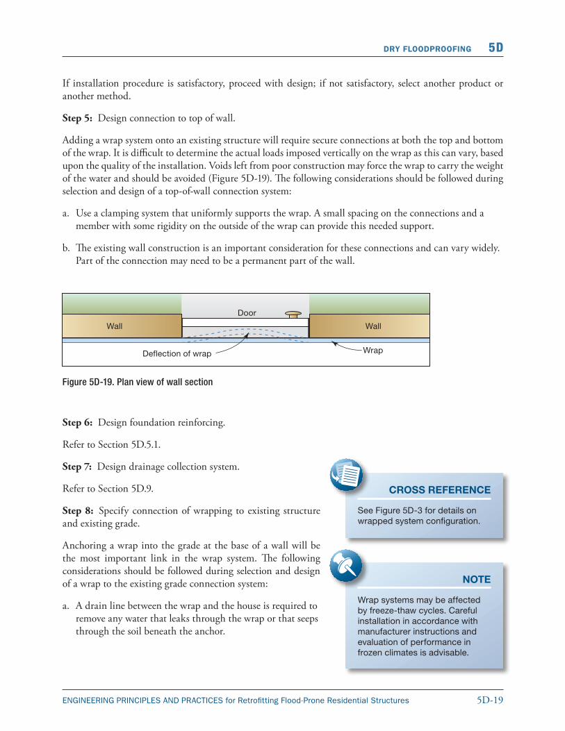
Adding a wrap system onto an existing structure will require secure connections at both the top and bottom of the wrap. It is difficult to determine the actual loads imposed vertically on the wrap as this can vary, based upon the quality of the installation. Voids left from poor construction may force the wrap to carry the weight of the water and should be avoided (Figure 5D-19). The following considerations should be followed during selection and design of a top-of-wall connection system:
a. Use a clamping system that uniformly supports the wrap. A small spacing on the connections and a member with some rigidity on the outside of the wrap can provide this needed support.
b. The existing wall construction is an important consideration for these connections and can vary widely. Part of the connection may need to be a permanent part of the wall.
Figure 5D-19. Plan view of wall section
Step 6: Design foundation reinforcing.
Refer to Section 5D.5.1.
Step 7: Design drainage collection system.
Refer to Section 5D.9.
Step 8: Specify connection of wrapping to existing structure and existing grade.
Anchoring a wrap into the grade at the base of a wall will be the most important link in the wrap system. The following considerations should be followed during selection and design of a wrap to the existing grade connection system:
a. A drain line between the wrap and the house is required to remove any water that leaks through the wrap or that seeps through the soil beneath the anchor.
CROSS REFERENCE
See Figure 5D-3 for details on wrapped system configuration.
NOTE
Wrap systems may be affected by freeze-thaw cycles. Careful instal lation in accordance with manufac turer instructions and evaluation of performance in frozen climates is advisable.
5D-20 ENGINEERING PRINCIPLES AND PRACTICES for Retrofitting Flood-Prone Residential Structures
5D DRY FLOODPROOFING
b. As with the top-of-wall connection, wrap forces are difficult to determine. It is best to follow details that have worked in the past and are compatible to the specific structure.
c. It is recommended that the end of the wrap be buried at least below the layer of topsoil. Additional ballast may be needed (sandbags, stone, etc.) to prevent wrap movement in a saturated and/or frozen soil condition.
d. The designer may want to refer to the product literature for wrap material and applicable codes and standards.
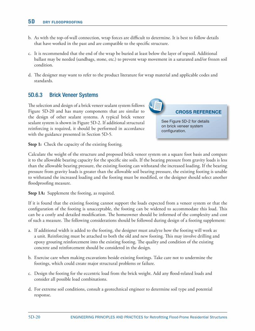
5D.6.3 Brick Veneer Systems
The selection and design of a brick veneer sealant system follows Figure 5D-20 and has many components that are similar to the design of other sealant systems. A typical brick veneer sealant system is shown in Figure 5D-2. If additional structural reinforcing is required, it should be performed in accordance with the guidance presented in Section 5D-5.
Step 1: Check the capacity of the existing footing.
Calculate the weight of the structure and proposed brick veneer system on a square foot basis and compare it to the allowable bearing capacity for the specific site soils. If the bearing pressure from gravity loads is less than the allowable bearing pressure, the existing footing can withstand the increased loading. If the bearing pressure from gravity loads is greater than the allowable soil bearing pressure, the existing footing is unable to withstand the increased loading and the footing must be modified, or the designer should select another floodproofing measure.
Step 1A: Supplement the footing, as required.
If it is found that the existing footing cannot support the loads expected from a veneer system or that the configuration of the footing is unacceptable, the footing can be widened to accommodate this load. This can be a costly and detailed modification. The homeowner should be informed of the complexity and cost of such a measure. The following considerations should be followed during design of a footing supplement:
a. If additional width is added to the footing, the designer must analyze how the footing will work as a unit. Reinforcing must be attached to both the old and new footing. This may involve drilling and epoxy grouting reinforcement into the existing footing. The quality and condition of the existing concrete and reinforcement should be considered in the design.
b. Exercise care when making excavations beside existing footings. Take care not to undermine the footings, which could create major structural problems or failure.
c. Design the footing for the eccentric load from the brick weight. Add any flood-related loads and consider all possible load combinations.
d. For extreme soil conditions, consult a geotechnical engineer to determine soil type and potential response.
CROSS REFERENCE
See Figure 5D-2 for details on brick veneer system configuration.
5D-21ENGINEERING PRINCIPLES AND PRACTICES for Retrofitting Flood-Prone Residential Structures
DRY FLOODPROOFING 5D
Figure 5D-20. Selection/design of a brick veneer sealant system
e. The designer may want to refer to ACI 318, Building Code Requirements for Structural Concrete and Commentary (ACI, 2008ba), a soils manual/textbook for detailed footing design, and to applicable codes and standards.
5D-22 ENGINEERING PRINCIPLES AND PRACTICES for Retrofitting Flood-Prone Residential Structures
5D DRY FLOODPROOFING
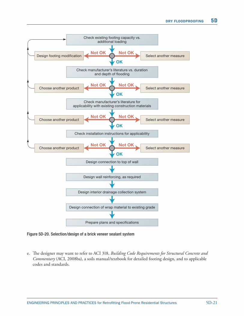
Step 1B: Design foundation reinforcing (as required).
Concrete footings can come in a wide variety of configurations. Design of footings, especially those involved with retaining of materials, can become quite complex. There are many books that deal with the design of special foundations and, once the stresses are determined, the ACI 318, Building Code Requirements for Structural Concrete and Commentary (ACI, 2008ba), can provide guidelines for concrete reinforcement design.
Steps 2–9 are similar to the design of wrapped sealant systems. Refer to the previous section for details on these steps.
Appendix C contains a design example that illustrates the process of analysis of a wood-framed wall system to resist flood and wind loads. Please note that ACI 530-08, Building Code Requirements for Masonry Structures (ACE, 2008b), does not allow veneers to be considered a structural load resisting system. The wall structural wall system must be capable of resisting the entire lateral loads applied. This same process should be used for any dry floodproofing measure.
5D.7 Selection and Design of Shield SystemsOnce the determination is made that a foundation system can withstand the expected flood and flood-related forces, the selection of a shield system is relatively straightforward and centers on the ability of the selected material to structurally secure the opening, be compatible with the existing construction materials, and be responsive to the duration and depth of flooding expected.
5D.7.1 Plate Shields
The selection and design of a plate shield follows Figure 5D-21. If additional existing structural reinforcing is required, it should be performed in accordance with the guidance presented in the preceding section.
Step 1: Select the plate shield material.
Plate shield material selection may be driven by the size of the opening or the duration of flooding. For example, plywood shields would not hold up during long-term flooding.
a. Consider flood duration and select steel or aluminum materials for long duration flooding and consider marine grade plywood materials for short duration flooding.
b. Consider opening size and select steel and aluminum materials with stiffeners for larger openings and shored plywood with appropriate bracing for small openings.
c. Installation of all shields should be quick and easy. Lighter materials such as plywood and aluminum are suitable for most homeowner installation.
NOTE
Industry has developed manufactured closure systems that may be applicable to specific situations. For additional information on the companies that manufacture these products, contact your local floodplain management or engineering office.
5D-23ENGINEERING PRINCIPLES AND PRACTICES for Retrofitting Flood-Prone Residential Structures
DRY FLOODPROOFING 5D
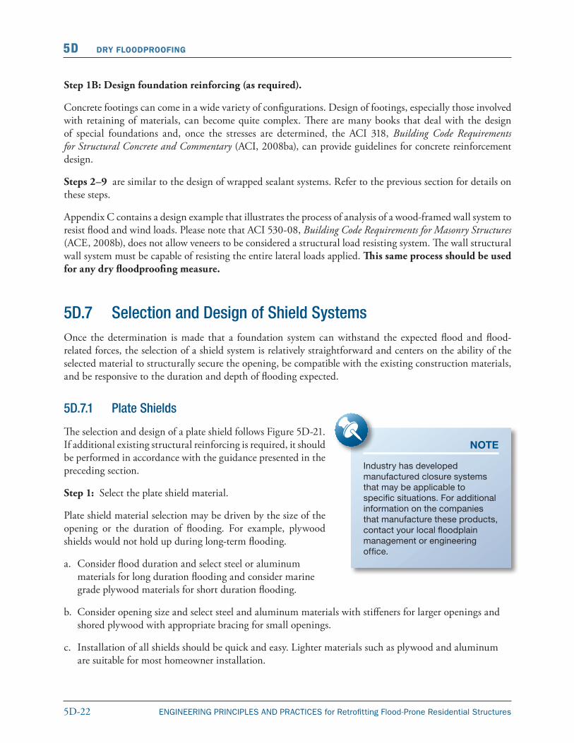
Step 2: Determine panel stresses.
The designer should check the shield panel either as a plate or a horizontal/vertical span across the opening.
a. Using end conditions and attachments to determine how the panel will work, calculate stresses based on bending of the plate. In larger plate applications, also compute the end shear.
b. Compare these stresses to the allowable stresses from the appropriate source.
c. Some shields may have a free end at the top or other unusual configuration. These will need to be addressed on a case-by-case basis.
d. Adjust the plate thickness to select the most economical section. If the plate does not work for larger thicknesses, add stiffeners.
e. The designer may want to refer to the AISC 325, Steel Construction Manual (AISC, 2005) for steel plate design, an aluminum design manual, Aluminum Association (AA), Aluminum Construction Manual
Figure 5D-21. Selection/design of plate shields
NOTE
The use of plywood shields in long-term exposure situations may induce possible swelling and deterioration of the laminating glue.
5D-24 ENGINEERING PRINCIPLES AND PRACTICES for Retrofitting Flood-Prone Residential Structures
5D DRY FLOODPROOFING
(AA, 1959), ANSI/AF&PA National Design Specification for Wood Construction (ANSI/AF&PA, 2005) for plywood design, and applicable codes and standards.
Step 3A: Check deflections.
A plate shield that is acceptable for stresses may not be acceptable for deflection.
a. Calculate deflections for the panel and evaluate on the basis of connections and sealants.
b. If the deflection is unacceptable, add stiffeners.
c. Deflection may be controlled by alternative plate materials.
d. The designer may want to refer to the AISC 325, Steel Construction Manual (AISC, 2005), the Aluminum Construction Manual (Aluminum Association [AA], 1959), the ANSI/AF&PA National Design Specification for Wood Construction (ANSI/AF&PA, 2005) for plywood design, and applicable codes and standards.
Step 3B: Stiffen as required.
Plate overstress or deflection may be solved through the use of stiffeners.
a. Select the section to be used as a stiffener. Angles may be used for steel or aluminum and wood stock for plywood.
b. Calculate the stresses and deflection based on the com posite section of stiffener and plate.
c. Calculate the horizontal shear between the two sections and design the connections to carry this load.
d. Keep plate connections and frame in mind when detailing stiffeners.
e. The designer may want to refer to the AISC 325, Steel Construction Manual (AISC, 2005), the Aluminum Construction Manual (Aluminum Association [AA], 1959), the ANSI/AF&PA National Design Specification for Wood Construction (ANSI/AF&PA, 2005) for plywood design, mechanics of materials tests, and applicable codes and standards.
Step 4A: Design the connections.
Plate connections must be easy to install and able to handle the loads from the plate into the frame and surrounding wall.
a. Determine the type of connection (hinged, free top, bolted, latching dogs, etc.).
b. Consider ease of installation and aesthetics.
c. Connection must operate in conjunction with gasket or sealant to prevent leakage.
d. Connection must be capable of resisting some forces in the direction opposite of surges.
e. The designer may want to refer to the AISC 325, Steel Construction Manual (AISC, 2005), for bolted connections; ACI 530, Building Code Requirements for Masonry Structures (ACI, 2008b), for connections into concrete and masonry, and applicable codes and standards.
5D-25ENGINEERING PRINCIPLES AND PRACTICES for Retrofitting Flood-Prone Residential Structures
DRY FLOODPROOFING 5D
Step 4B: Select the gasket or waterproofing.
Gaskets or waterproofing materials, which form the interface between shields and the existing structure, are vital elements of the dry floodproofing system. They should be flexible, durable, and applicable to the specific situation.
a. Determine the type of gasket or waterproofing required.
b. Consider ease of installation and ability to work with plate/connections as a single unit.
c. Gasket/waterproofing must be able to withstand expected forces.
d. Gasket/waterproofing must be able to function during climatic extremes.
e. The designer should refer to manufacturer’s literature and check against duration/depth of flooding and applicability to selected building materials.
Step 6: Check adjacent walls, lintels, sills, and top/bottom connections.
Structural components adjacent to the shield panel, such as adjacent walls, lintels, sills, and top/bottom connections, should be checked against maximum loading conditions. Different methods of attachment may load the adjacent wall differently.
Walls adjacent to the shield should be anchored into the footing to resist base shear. Lintels/sills should be checked for biaxial bending resulting from lateral loading. Top connections should be evaluated for shear resistance and ability to transfer loads to the joists.
5D.8 Construction Considerations for Sealants and ShieldsThe use of sealants and shields may require careful attention to critical installation activities. When using shields and sealants, it is vital that:
� the sealant be applied in accordance with the manufacturer’s instructions;
� wrapped systems are anchored properly and the surrounding soil recompacted;
� shields are tightly installed with associated caulking or gaskets, utilizing the proper grade of materials and paying close attention to the anchoring details; and
� multiple closures are accurately labeled and stored in an easily accessible space.
5D.9 Drainage Collection SystemsThe expected reductions in hydrostatic loading imposed on the building from floodwaters depend on many factors. Drainage systems are typically designed to eliminate excess hydrostatic loads from storm runoff or high water tables and not high floodwaters. For short duration flooding at low levels, underdrain systems may reduce flood loads for dry floodproofing designs. These systems may also be utilized in concert with
5D-26 ENGINEERING PRINCIPLES AND PRACTICES for Retrofitting Flood-Prone Residential Structures
5D DRY FLOODPROOFING
elevation, floodwall, and levee measures. These systems collect drainage and seepage from areas along, adjacent to, or inside the retrofitting measure and the sump pump installation, which transmits the collected drainage and seepage away from the building’s foundation. Determination of the amount of surface water inflow and infiltration was presented in Chapter 4. This section presents the parameters that govern the design of these systems.
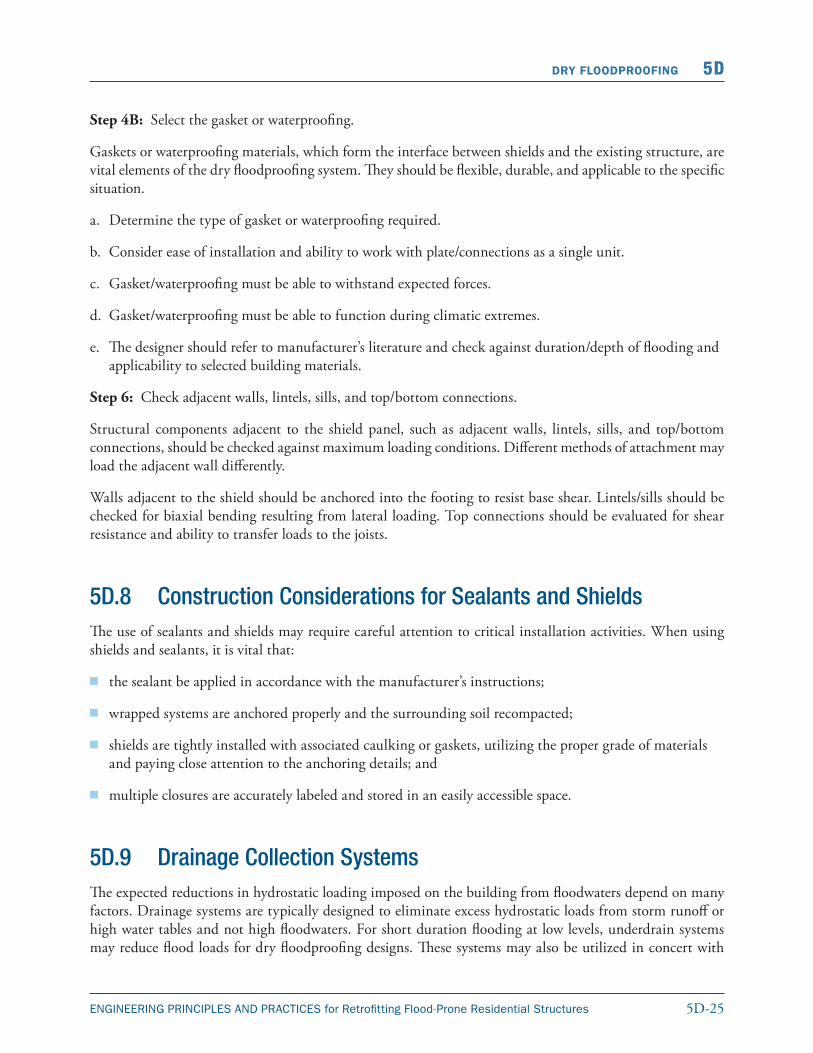
Typical homes with basements are constructed on concrete footings upon which concrete or CMU block foundation walls are constructed. In some instances, the foundation walls are parged, and covered with a waterproof coating and/or perforated pipe underdrains are installed to carry water away from the exterior foundation walls (see Figure 5D-22). The excavations are then backfilled and compacted.
Check building codes to see if any maximum heights of unbalanced fill requirements apply for the given construction. However, in practice, this fill material is not and often cannot be compacted to a density equal to that of the undisturbed soils around the house. Because of the density difference, the fill material is capable of conducting and holding more water than the soil around it and frequently provides a storage area for the soil water. As flood levels rise around the structure, the combined water and soil pressure in the areas
NOTE
Check building codes to see if any maximum height of unbalanced fill requirements apply for the given construction.
Figure 5D-22.Typical residential masonry block wall construction
5D-27ENGINEERING PRINCIPLES AND PRACTICES for Retrofitting Flood-Prone Residential Structures
DRY FLOODPROOFING 5D
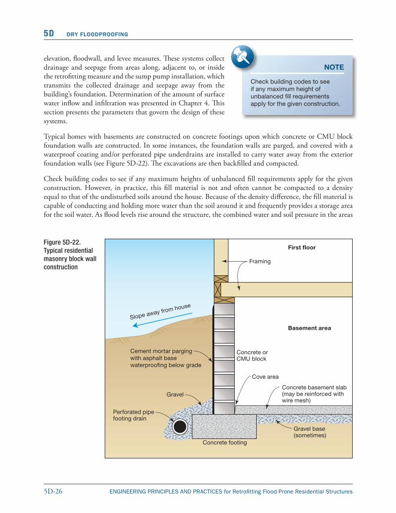
adjacent to the foundation increases to the point of cracking foundation walls and/or entering the basement through existing cracks to relieve the pressure (see Figure 5D-23).
Figure 5D-23.Common faults contributing to seepage into basements
Depending upon site-specific soil conditions, high water tables, and local drainage characteristics, slab-on-grade houses may experience similar seepage problems. In addition, elevating and/or dry floodproofing a slab-on-grade house may also necessitate the installation of drainage collection systems to counteract buoyancy and lateral hydrostatic forces. Drainage collection systems consisting of perforated pipe drains are designed to collect this water and discharge it away from the structure, thereby relieving the pressure buildup against the foundation walls. Several types of drainage collection systems exist, including French drains, exterior underdrains, and interior drains. Poorly conceived drainage collection systems can result in water being drained into sumps at a rate that will exceed the capacity practical methods for removing the water (e.g., sump pumps). Although these systems typically drain storm runoff, excessive flood loads can overwhelm sump pumps and flood basements. Drainage systems may provide the most benefit to properties that are adjacent to floodplains where floodwaters may quickly elevate the water table a few feet above normal. In these situations, drainage systems may limit water seepage into basements or the lowest floors.
5D-28 ENGINEERING PRINCIPLES AND PRACTICES for Retrofitting Flood-Prone Residential Structures
5D DRY FLOODPROOFING
5D.9.1 French Drains
French drains are used to help dewater saturated soil adjacent to a foundation. They are simply trenches filled with gravel, filter fabric, and sometimes plastic pipe. A typical French drain section is shown in Figure 5D-24. The effectiveness of French drains is closely tied to the existence of a suitable discharge point and the slope/depth of the trench. A suitable discharge for the drain usually means an open stream, swale, ditch, or slope to which the drain can be run. If such a discharge point is not available, a French drain is generally not feasible.
If feasible, the French drain should be dug to a sufficient depth to ensure the capture of soil water that might infiltrate the fill material in the footing area of the basement. The slope of the trench should be such that good flow can be maintained between the gravel stones. This typically means a minimum slope of 1.0 percent or more.
NOTE
French drains are generally not suitable for areas subject to fre quent inundation due to the lack of a gravity discharge point during a flood. However, they can be ef fective in keeping localized drain age away from the foundation (providing a significant flood doesn’t occur). In some flood conditions, French drains can provide an easy way for floodwaters to inundate a foundation.
Figure 5D-24.Typical French drain system
5D.9.2 Exterior Underdrain Systems
Exterior underdrain systems are generally the most reliable drainage collection system when combined with some type of foundation parging and waterproofing. Their chief advantage is that they will remove water that would otherwise exert pressure against the foundation walls and floors.
Underdrains are normally constructed of continuous perforated plastic pipe laid on a gravel filter bed, with drain holes facing up. The underdrains are placed along the building foundation just below the footing and carry water that collects to a gravity discharge or sump pump for disposal into a public drainage system, natural drainage course, or ground surface as permitted by local agencies (see Figures 5D-25 and 5D-26). These systems may not be sufficient when water tables or floodwaters exceed a few feet above the lowest floor (or basement).
NOTE
Similar to the French drain, an exterior underdrain system with gravity discharge will not work during a flood. Sump pump discharge with a backup energy source may provide some dewatering benefits in more frequent low-level flooding conditions, but may not be sufficient in high floodwaters.
5D-29ENGINEERING PRINCIPLES AND PRACTICES for Retrofitting Flood-Prone Residential Structures
DRY FLOODPROOFING 5D
Figure 5D-25. Typical exterior underdrain system with sump pump showing two alternative configurations in the side view
5D.9.3 Interior Drain System
Interior drain systems are designed to relieve hydrostatic pressure from the exterior basement walls and floors and do not require that the soil be excavated from around the exterior basement walls for installation. Sump pumps are perhaps the most familiar of all methods used to dewater basements. The sump is generally constructed so that its bottom is well below the base of the basement floor slab. Water in the areas adjacent to the basement walls and floor migrate toward the area of least pressure along the lines of least resistance, in this case toward and into the sump. It may be necessary to provide a more readily accessible path of least resistance for water that has collected in the fill material and around the house to follow. To achieve this, pipe segments are inserted and sometimes drilled through the basement wall and into the fill behind. These pipe seg ments are then connected to larger diameter pipes running along a gravel-filled trench or cove area into the basement floor and into one or more sumps (see Figure 5D-27). These systems may be overwhelmed by quickly rising water tables.
5D-30 ENGINEERING PRINCIPLES AND PRACTICES for Retrofitting Flood-Prone Residential Structures
5D DRY FLOODPROOFING
Figure 5D-26. Details of a combination underdrain and foundation waterproofing system
Figure 5D-27. Typical interior drain systems
5D-31ENGINEERING PRINCIPLES AND PRACTICES for Retrofitting Flood-Prone Residential Structures
DRY FLOODPROOFING 5D
5D.9.4 Types of Sump Pumps
Two types of sump pumps commonly used are the submersible and the pedestal. The submersible type has a watertight motor that is directly connected to the pump casing and installed at the bottom of the sump. The pedestal sump pump uses an open motor supported on a pipe column with the pump at its base. A long shaft inside the column connects the motor to the pump impeller. Figure 5D-28 depicts both of these pumps. Submersible pumps are preferred because they will continue to operate if the flood level exceeds the height of the pump.
In selecting a sump pump for use in residential floodproofing, the designer should consider the advantages of each pump type and make a selection based on requirements determined from investigation of the residence. Considerations include pump capacity (gpm or gallons per hour [gph]), pump head (vertical height that the water is lifted), and electrical power required (residential electrical power is usually 120/240 volts AC, single phase). Sump pump motors generally range in size from 1/4 horsepower to 1/2 horsepower designed to operate on either 120 or 240 volts.
Figure 5D-28. Types of sump pumps
NOTE
Battery powered marine-type bilge pumps are an alternative to sump pumps/electrical generator installations.
5D-32 ENGINEERING PRINCIPLES AND PRACTICES for Retrofitting Flood-Prone Residential Structures
5D DRY FLOODPROOFING
The type of float switch system to turn on the pump is also an important component. Many pumps use one of four types of switches. The diaphragm switch is activated by water pressure and is the most expensive type, but not necessarily the most reliable. A vertical action float switch has a float attached to a vertical rod, which activates the switch as it rises from the water level. This is inexpensive and relatively reliable. The tethered float switch works similar to the vertical action, but is only tethered by a line instead of a vertical rod. This method is inexpensive, but can experience many problems. The final common option is an electronic float free switch, which uses a wire that senses contact with water. This switch system may also include an audible alarm and some more expensive units also include options for connecting a backup pump. While all of these are viable options for residential application, it is important to evaluate the benefits and understand the reliability of each system.
If a pump system is depended on for dry floodproofing, it is important to verify that the pump(s) are working properly. One of the most common failure modes with sump pumps is the malfunction of the switch from internal or external causes. It is important to be familiar with pump switches and the proper procedure for replacing the switch. Although this can be an inexpensive part, the malfunction of a switch can negate the effectiveness of other floodproofing measures. Other common issues are an improperly working float (tells the sump pump when to operate), this may be caused by an obstruction that needs to be cleared or debris attached to the float, which make it less buoyant. A blocked intake or impeller is another issue associated with the failure of sump pumps to operate properly. Prior to doing any maintenance on a sump pump, it is important to make sure it is unplugged or disconnected from its power source.
5D.9.5 Infiltration versus Inundation
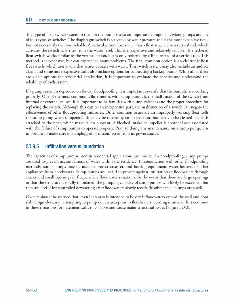
The capacities of sump pumps used in residential applications are limited. In floodproofing, sump pumps are used to prevent accumulations of water within the residence. In conjunction with other floodproofing methods, sump pumps may be used to protect areas around heating equipment, water heaters, or other appliances from floodwaters. Sump pumps are useful to protect against infiltration of floodwaters through cracks and small openings in frequent low floodwater situations. In the event that there are large openings or that the structure is totally inundated, the pumping capacity of sump pumps will likely be exceeded, but they are useful for controlled dewatering after floodwaters slowly recede (if submersible pumps are used).
Owners should be warned that, even if an area is intended to be dry if floodwaters exceed the wall and floor slab design elevation, attempting to pump out an area prior to floodwaters receding is unwise. It is common in these situations for basement walls to collapse and cause major structural issues (Figure 5D-29).
5D-33ENGINEERING PRINCIPLES AND PRACTICES for Retrofitting Flood-Prone Residential Structures
DRY FLOODPROOFING 5D
Figure 5D-29. Foundation wall failure due to pumping out basement while ground was still saturated with water
5D.9.6 Coordination with Other Floodproofing Methods
Design and installation of a sump pump should be coordinated with other floodproofing methods such as sealants and shields, protection of utility systems (furnaces, water heaters, etc.), and emergency power.
5D.9.7 Field Investigation
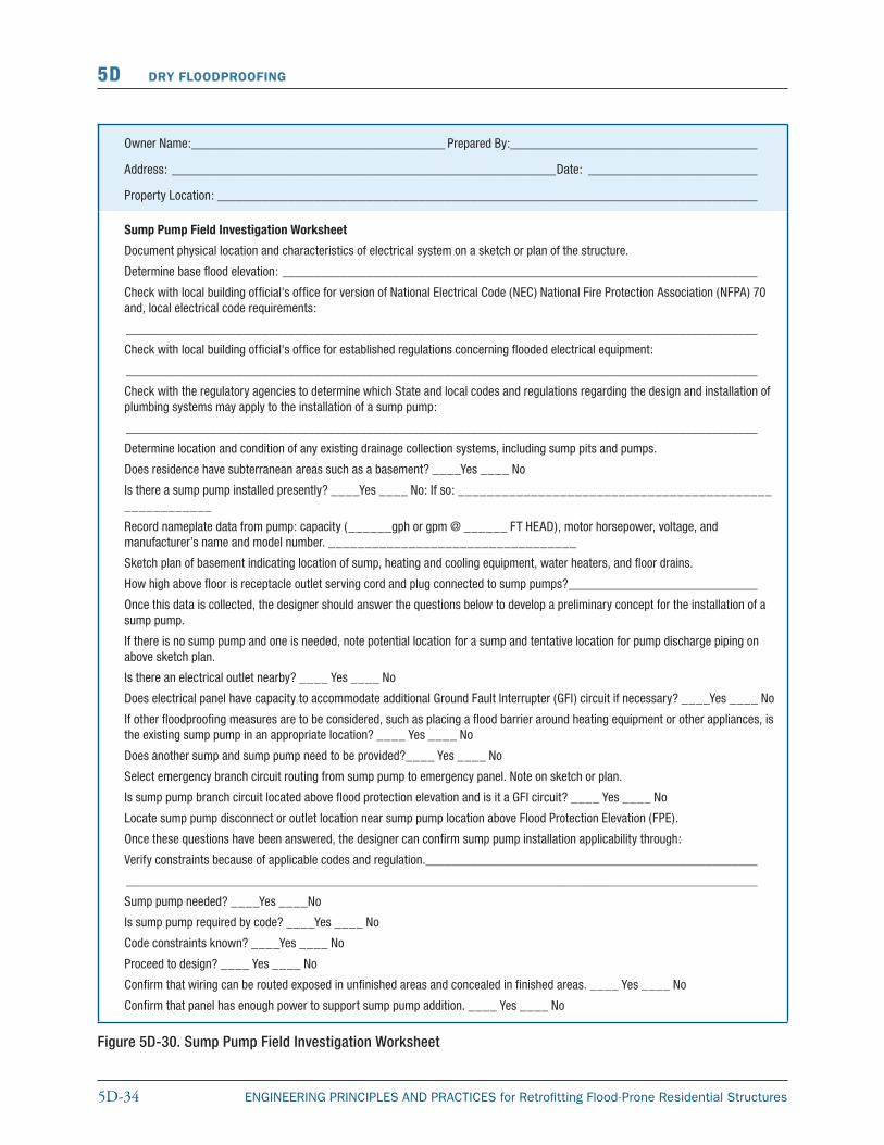
Detailed information about the existing structure must be obtained to make decisions and calculations concerning the feasibility of using a sump pump. Use Figures 5-2 and 5-3 as a guide to record information about the residence. Items that the designer may require are covered in the sump pump field investigation worksheet (see Figure 5D-30).
5D-34 ENGINEERING PRINCIPLES AND PRACTICES for Retrofitting Flood-Prone Residential Structures
5D DRY FLOODPROOFING
Owner Name: _______________________________________ Prepared By:______________________________________
Address: ___________________________________________________________Date: __________________________
Property Location: ___________________________________________________________________________________
Sump Pump Field Investigation Worksheet
Document physical location and characteristics of electrical system on a sketch or plan of the structure.
Determine base flood elevation: _________________________________________________________________________
Check with local building official's office for version of National Electrical Code (NEC) National Fire Protection Association (NFPA) 70 and, local electrical code requirements:
_________________________________________________________________________________________________
Check with local building official's office for established regulations concerning flooded electrical equipment:
_________________________________________________________________________________________________
Check with the regulatory agencies to determine which State and local codes and regulations regarding the design and installation of plumbing systems may apply to the installation of a sump pump:
_________________________________________________________________________________________________
Determine location and condition of any existing drainage collection systems, including sump pits and pumps.
Does residence have subterranean areas such as a basement? ____Yes ____ No
Is there a sump pump installed presently? ____Yes ____ No: If so: _______________________________________________________
Record nameplate data from pump: capacity (______gph or gpm @ ______ FT HEAD), motor horsepower, voltage, and manufacturer’s name and model number. __________________________________
Sketch plan of basement indicating location of sump, heating and cooling equipment, water heaters, and floor drains.
How high above floor is receptacle outlet serving cord and plug connected to sump pumps? _____________________________
Once this data is collected, the designer should answer the questions below to develop a preliminary concept for the installation of a sump pump.
If there is no sump pump and one is needed, note potential location for a sump and tentative location for pump discharge piping on above sketch plan.
Is there an electrical outlet nearby? ____ Yes ____ No
Does electrical panel have capacity to accommodate additional Ground Fault Interrupter (GFI) circuit if necessary? ____Yes ____ No
If other floodproofing measures are to be considered, such as placing a flood barrier around heating equipment or other appliances, is the existing sump pump in an appropriate location? ____ Yes ____ No
Does another sump and sump pump need to be provided?____ Yes ____ No
Select emergency branch circuit routing from sump pump to emergency panel. Note on sketch or plan.
Is sump pump branch circuit located above flood protection elevation and is it a GFI circuit? ____ Yes ____ No
Locate sump pump disconnect or outlet location near sump pump location above Flood Protection Elevation (FPE).
Once these questions have been answered, the designer can confirm sump pump installation applicability through:
Verify constraints because of applicable codes and regulation.___________________________________________________
_________________________________________________________________________________________________
Sump pump needed? ____Yes ____No
Is sump pump required by code? ____Yes ____ No
Code constraints known? ____Yes ____ No
Proceed to design? ____ Yes ____ No
Confirm that wiring can be routed exposed in unfinished areas and concealed in finished areas. ____ Yes ____ No
Confirm that panel has enough power to support sump pump addition. ____ Yes ____ No
Figure 5D-30. Sump Pump Field Investigation Worksheet
5D-35ENGINEERING PRINCIPLES AND PRACTICES for Retrofitting Flood-Prone Residential Structures
DRY FLOODPROOFING 5D
5D.9.8 Design
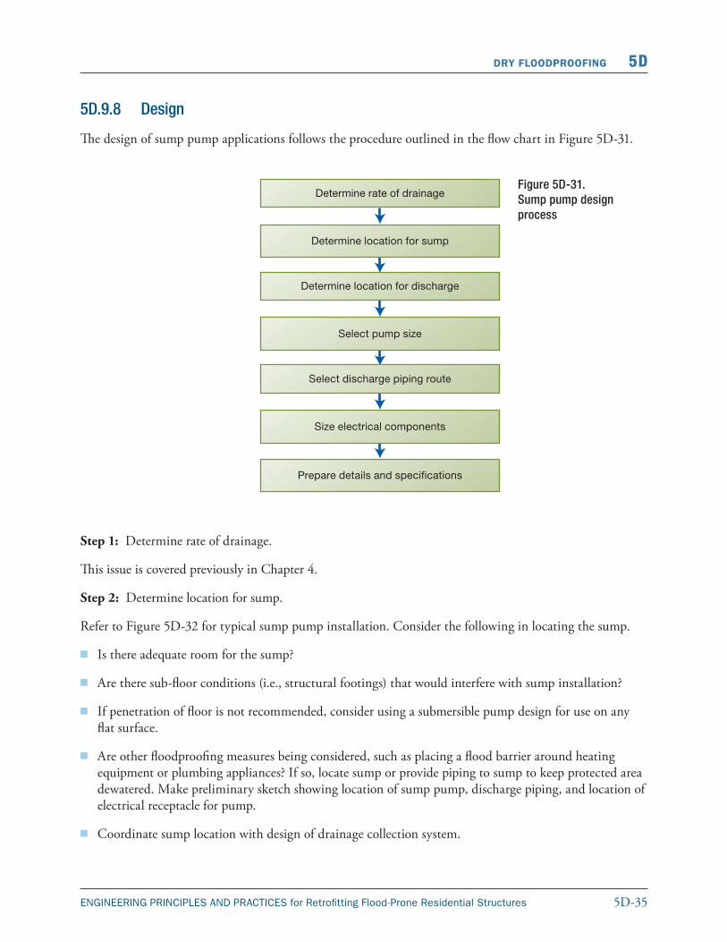
The design of sump pump applications follows the procedure outlined in the flow chart in Figure 5D-31.
Figure 5D-31. Sump pump design process
Step 1: Determine rate of drainage.
This issue is covered previously in Chapter 4.
Step 2: Determine location for sump.
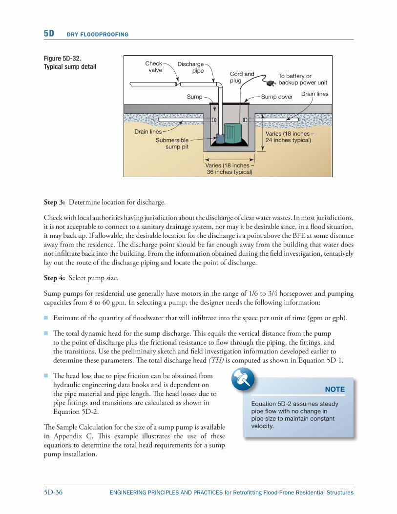
Refer to Figure 5D-32 for typical sump pump installation. Consider the following in locating the sump.
� Is there adequate room for the sump?
� Are there sub-floor conditions (i.e., structural footings) that would interfere with sump installation?
� If penetration of floor is not recommended, consider using a submersible pump design for use on any flat surface.
� Are other floodproofing measures being considered, such as placing a flood barrier around heating equipment or plumbing appliances? If so, locate sump or provide piping to sump to keep protected area dewatered. Make preliminary sketch showing location of sump pump, discharge piping, and location of electrical receptacle for pump.
� Coordinate sump location with design of drainage collection system.
5D-36 ENGINEERING PRINCIPLES AND PRACTICES for Retrofitting Flood-Prone Residential Structures
5D DRY FLOODPROOFING
Step 3: Determine location for discharge.
Check with local authorities having jurisdiction about the discharge of clear water wastes. In most jurisdictions, it is not acceptable to connect to a sanitary drainage system, nor may it be desirable since, in a flood situation, it may back up. If allowable, the desirable location for the discharge is a point above the BFE at some distance away from the residence. The discharge point should be far enough away from the building that water does not infiltrate back into the building. From the information obtained during the field investigation, tentatively lay out the route of the discharge piping and locate the point of discharge.
Step 4: Select pump size.
Sump pumps for residential use generally have motors in the range of 1/6 to 3/4 horsepower and pumping capacities from 8 to 60 gpm. In selecting a pump, the designer needs the following information:
� Estimate of the quantity of floodwater that will infiltrate into the space per unit of time (gpm or gph).
� The total dynamic head for the sump discharge. This equals the vertical distance from the pump to the point of discharge plus the frictional resistance to flow through the piping, the fittings, and the transitions. Use the preliminary sketch and field investigation information developed earlier to determine these parameters. The total discharge head (TH) is computed as shown in Equation 5D-1.
� The head loss due to pipe friction can be obtained from hydraulic engineering data books and is dependent on the pipe material and pipe length. The head losses due to pipe fittings and transitions are calculated as shown in Equation 5D-2.
The Sample Calculation for the size of a sump pump is available in Appendix C. This example illustrates the use of these equations to determine the total head requirements for a sump pump installation.
Figure 5D-32. Typical sump detail
NOTE
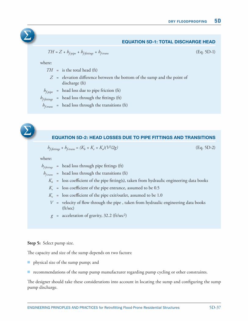
Equation 5D-2 assumes steady pipe flow with no change in pipe size to maintain constant velocity.
5D-37ENGINEERING PRINCIPLES AND PRACTICES for Retrofitting Flood-Prone Residential Structures
DRY FLOODPROOFING 5D
(Eq. 5D-1)
EQUATION 5D-1: TOTAL DISCHARGE HEAD
TH = Z + hf-pipe + hf-fittings + hf-trans
where: TH = is the total head (ft) Z = elevation difference between the bottom of the sump and the point of
discharge (ft) hf-pipe = head loss due to pipe friction (ft) hf-fittings = head loss through the fittings (ft) hf-trans = head loss through the transitions (ft)
EQUATION 5D-2: HEAD LOSSES DUE TO PIPE FITTINGS AND TRANSITIONS
hf-fittings + hf-trans = (Kb + Ke + Ko)(V2/2g) (Eq. 5D-2)
where: hf-fittings = head loss through pipe fittings (ft) hf-trans = head loss through the transitions (ft) Kb = loss coefficient of the pipe fitting(s), taken from hydraulic engineering data books Ke = loss coefficient of the pipe entrance, assumed to be 0.5 Ko = loss coefficient of the pipe exit/outlet, assumed to be 1.0 V = velocity of flow through the pipe , taken from hydraulic engineering data books
(ft/sec) g = acceleration of gravity, 32.2 (ft/sec2)
Step 5: Select pump size.
The capacity and size of the sump depends on two factors:
� physical size of the sump pump; and
� recommendations of the sump pump manufacturer regarding pump cycling or other constraints.
The designer should take these considerations into account in locating the sump and configuring the sump pump discharge.
5D-38 ENGINEERING PRINCIPLES AND PRACTICES for Retrofitting Flood-Prone Residential Structures
5D DRY FLOODPROOFING
Step 6: Select discharge piping route:
� measure minimize length of pipe between sump and discharge point;
� avoid utility and structural components along route;
� attach discharge pipe to structure as required by code; and
� protect discharge point against erosion.
Step 7: Size electrical components:
� obtain horsepower and full load amperage rating for sump pump;
� select GFI circuit, as required by code;
� size minimum circuit ampacity and maximum fuse size;
� size maximum circuit breaker size; and
� obtain recommended fuse size or circuit breaker size from manufacturer and compare to above maximum and minimum NEC sizes.
At this point, the designer should prepare a floor plan sketch showing the location of the sump pump, routing of discharge line, location of discharge point, and preliminary specifications for the sump pump, sump, piping, and appurtenances, and confirm the preliminary design with the homeowner, covering the following items:
� verify that proposed location of sump pump is feasible;
� verify electrical availability for sump pump;
� verify existing conditions along proposed routing of discharge piping and at location of discharge pipe termination;
� confirm selection and size of sump pump;
� confirm size and location of sump; and
� confirm special considerations regarding existing conditions affecting design and installation of sump pump and sump.
Step 8: Create details and specifications and prepare final plans showing:
� floor plan with location of sump and backwater valves;
� routing of discharge pipe and location of termination;
� details, notes, and schedules;
� sump pump detail;
5D-39ENGINEERING PRINCIPLES AND PRACTICES for Retrofitting Flood-Prone Residential Structures
DRY FLOODPROOFING 5D
� wall, floor, and wall penetration details:
� sump construction details;
� installation notes;
� equipment notes (or schedule); and
� discharge pipe termination;
� prepare specifications (on drawing or as a specifications booklet):
� pipe and fittings;
� insulation;
� hangers and supports;
� valves (including backwater valves); and
� sump pumps.
Coordinate plans with work of others on additional floodproofing measures that may be proposed at the same residence.
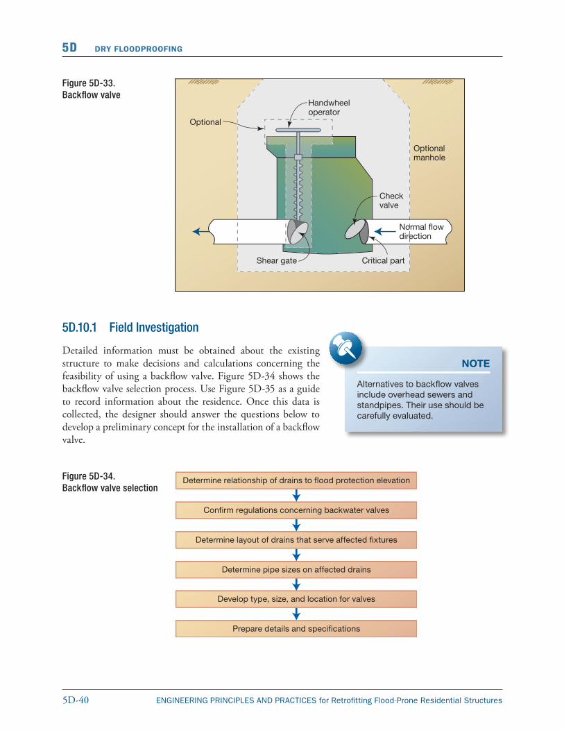
5D.10 Backflow Valves Backflow valves can help prevent backflow through the sanitary sewer and/or drainage systems into the house. They should be considered for sanitary sewer drainage systems that have fixtures below the FPE. In some instances, combined sewers (sanitary and storm) present the greatest need for backflow valves because they can prevent both a health and flooding hazard. Backflow valves are not foolproof: their effectiveness can be reduced because of fouling of the internal mechanism by soil or debris. Periodic maintenance is required.
The backflow valve is similar to a check valve used in domestic water systems (see Figure 5D-33). It has an internal hinged plate that opens in the normal direction of flow. If flow is reversed (“backflow”), the hinged plate closes over the inlet to the valve. The valve generally has a cast-iron body with a removable cover for access and corrosion-resistant internal parts. The valves are available in nominal sizes from 2 to 8 inches in diameter.
As an added feature, some manufacturers include a shear gate mechanism that can be manually operated to close the drain line when backflow conditions exist. The valve would remain open during normal use. A second type of backflow valve is a ball float check valve (see Figure 5D-34) that can be installed on the bottom of outlet floor drains to prevent water from flowing up through the drain. This type of valve is often built into floor drains or traps in newer construction.
Advanced backflow valve systems have ejector pump attachments that are used to pump sewage around the backflow valve, forcing it into the sewer system during times of flooding. This system is useful in maintaining normal operation of sanitary and drainage system components during a flood. Figure 5D-33 presents the backflow valve design process.
NOTE
Depending upon the hydrostatic pressure in the sewer system, a simple wood plug can be used to close floor drains.
5D-40 ENGINEERING PRINCIPLES AND PRACTICES for Retrofitting Flood-Prone Residential Structures
5D DRY FLOODPROOFING
Figure 5D-33. Backflow valve
5D.10.1 Field Investigation
Detailed information must be obtained about the existing structure to make decisions and calculations concerning the feasibility of using a backflow valve. Figure 5D-34 shows the backflow valve selection process. Use Figure 5D-35 as a guide to record information about the residence. Once this data is collected, the designer should answer the questions below to develop a preliminary concept for the installation of a backflow valve.
Figure 5D-34.Backflow valve selection
NOTE
Alternatives to backflow valves include overhead sewers and standpipes. Their use should be carefully evaluated.
5D-41ENGINEERING PRINCIPLES AND PRACTICES for Retrofitting Flood-Prone Residential Structures
DRY FLOODPROOFING 5D
5D.10.2 Design
The designer should follow the process illustrated in Figure 5D-34.
Owner Name: _______________________________________ Prepared By:______________________________________
Address: ___________________________________________________________Date: __________________________
Property Location: ___________________________________________________________________________________
Backflow Valve Field Investigation Worksheet
Does residence have plumbing fixtures or floor drains below flood protection elevation (FPE): ____ Yes ____ No
Is building drainage system equipped with backflow valves, or do floor drains have backflow device? ____ Yes ____ No:
If so, locate on a floor plan sketch of the residence.
If there are no backflow valves and they are needed, consider the following in selecting a location for their installation.
Can adequate clearance be maintained to remove access cover and service valve? ____ Yes ____ No
Are there any codes that regulate or restrict installation of such valves? ____ Yes ____ No
If yes, explain: ______________________________________________________________________________________
Tentatively locate on sketch box where backflow valves might be installed.
Proceed To Design? _____Yes _____No
Figure 5D-35. Backflow Valve Field Investigation Worksheet
The elements of this process include:
Step 1: Determine relationship of drains to FPE.
If any drain or pipe fixtures are located below the FPE, backflow valves should be installed. If all drains and fixtures are located above the FPE, backflow valves are not necessary.
Step 2: Confirm regulations concerning backflow valves.
Based upon information collected during the field investigation, confirm the regulations governing the installation of backflow valves.
Step 3: Determine layout of drains that serve the impacted fixtures.
Make a floor plan sketch showing location of all plumbing fixtures and appliances, floor drains, and drain piping below the FPE.
Step 4: Determine pipe sizes on impacted drains.
Obtain the size of drainage lines below the FPE from the field investigation.
Step 5: Determine type, size, and location for valves.
5D-42 ENGINEERING PRINCIPLES AND PRACTICES for Retrofitting Flood-Prone Residential Structures
5D DRY FLOODPROOFING
Determine type, size, and location of backflow valves required, paying considerable attention to any special conditions related to installation. Factors to be considered include:
� clearance for access and maintenance;
� cutting and patching of concrete floors; and
� indicating on the floor plan sketch the tentative location(s) of the backflow valve(s).
At this point, the designer should confirm the preliminary design with the homeowner, discussing the following items:
� verify that proposed locations of backflow valves are feasible;
� verify existing conditions at location of proposed backflow valve installation;
� confirm the size and location of needed backflow valves; and
� confirm special considerations regarding existing conditions affecting design and installation of backflow valves.
Step 6: Prepare details and specifications.
The final plans and specifications should include the following items:
� floor plan with location of backflow valves;
� details, notes, and schedules:
� backflow valve detail;
� wall, floor, and wall penetration details;
� installation notes; and
� equipment notes (or schedule);
� specifications governing the installation of:
� pipes and fittings;
� insulation;
� hangers and supports; and
� valves.
Coordinate plans with work of others on additional floodproofing measures that may be proposed at the same residence.
NOTE
If possible, backflow valves should be located outside a structure so as to minimize damage should the pressurized line fail.
5D-43ENGINEERING PRINCIPLES AND PRACTICES for Retrofitting Flood-Prone Residential Structures
DRY FLOODPROOFING 5D
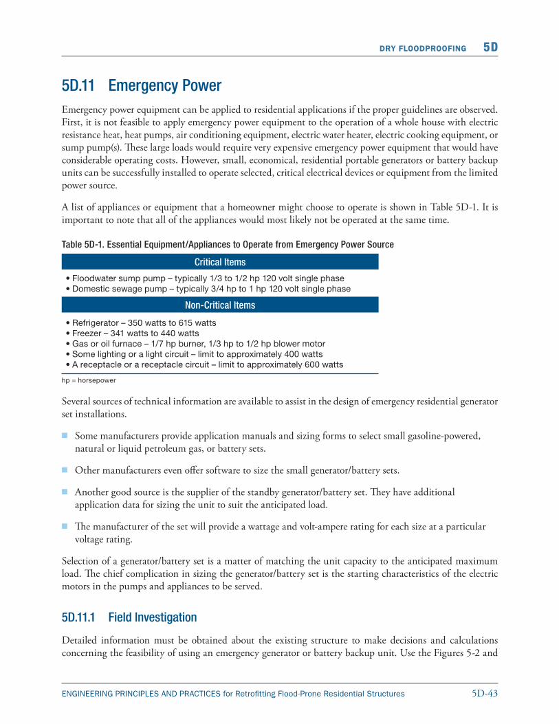
5D.11 Emergency PowerEmergency power equipment can be applied to residential applications if the proper guidelines are observed. First, it is not feasible to apply emergency power equipment to the operation of a whole house with electric resistance heat, heat pumps, air conditioning equipment, electric water heater, electric cooking equipment, or sump pump(s). These large loads would require very expensive emergency power equipment that would have considerable operating costs. However, small, economical, residential portable genera tors or battery backup units can be successfully installed to operate selected, critical electrical devices or equipment from the limited power source.
A list of appliances or equipment that a homeowner might choose to operate is shown in Table 5D-1. It is important to note that all of the appliances would most likely not be operated at the same time.
Table 5D-1. Essential Equipment/Appliances to Operate from Emergency Power Source
Critical Items
•Floodwater sump pump – typically 1/3 to 1/2 hp 120 volt single phase•Domestic sewage pump – typically 3/4 hp to 1 hp 120 volt single phase
Non-Critical Items
•Refrigerator – 350 watts to 615 watts•Freezer – 341 watts to 440 watts•Gas or oil furnace – 1/7 hp burner, 1/3 hp to 1/2 hp blower motor •Some lighting or a light circuit – limit to approximately 400 watts •A receptacle or a receptacle circuit – limit to approximately 600 watts
hp = horsepower
Several sources of technical information are available to assist in the design of emergency residential generator set installations.
� Some manufacturers provide application manuals and sizing forms to select small gasoline-powered, natural or liquid petroleum gas, or battery sets.
� Other manufacturers even offer software to size the small generator/battery sets.
� Another good source is the supplier of the standby generator/battery set. They have additional application data for sizing the unit to suit the anticipated load.
� The manufacturer of the set will provide a wattage and volt-ampere rating for each size at a particular voltage rating.
Selection of a generator/battery set is a matter of matching the unit capacity to the anticipated maximum load. The chief complication in sizing the generator/battery set is the starting characteristics of the electric motors in the pumps and appliances to be served.
5D.11.1 Field Investigation
Detailed information must be obtained about the existing structure to make decisions and calculations concerning the feasibility of using an emergency generator or battery backup unit. Use the Figures 5-2 and
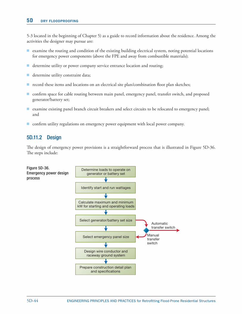
5D-44 ENGINEERING PRINCIPLES AND PRACTICES for Retrofitting Flood-Prone Residential Structures
5D DRY FLOODPROOFING
5-3 located in the beginning of Chapter 5) as a guide to record information about the residence. Among the activities the designer may pursue are:
� examine the routing and condition of the existing building electrical system, noting potential locations for emergency power components (above the FPE and away from combustible materials);
� determine utility or power company service entrance location and routing;
� determine utility constraint data;
� record these items and locations on an electrical site plan/combination floor plan sketches;
� confirm space for cable routing between main panel, emergency panel, transfer switch, and proposed generator/battery set;
� examine existing panel branch circuit breakers and select circuits to be relocated to emergency panel; and
� confirm utility regulations on emergency power equipment with local power company.
5D.11.2 Design
The design of emergency power provisions is a straightforward process that is illustrated in Figure 5D-36. The steps include:
Figure 5D-36.Emergency power design process
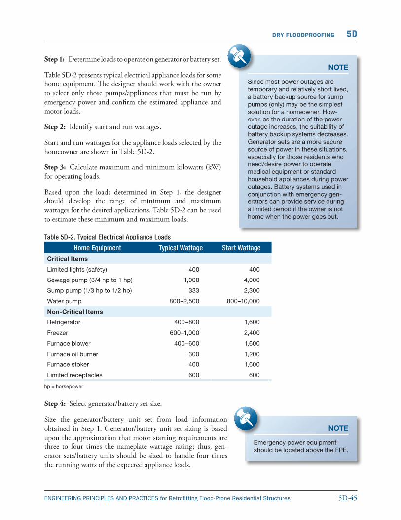
5D-45ENGINEERING PRINCIPLES AND PRACTICES for Retrofitting Flood-Prone Residential Structures
DRY FLOODPROOFING 5D
Step 1: Determine loads to operate on generator or battery set.
Table 5D-2 presents typical electrical appliance loads for some home equipment. The designer should work with the owner to select only those pumps/appliances that must be run by emergency power and confirm the estimated appliance and motor loads.
Step 2: Identify start and run wattages.
Start and run wattages for the appliance loads selected by the homeowner are shown in Table 5D-2.
Step 3: Calculate maximum and minimum kilowatts (kW) for operating loads.
Based upon the loads determined in Step 1, the designer should develop the range of minimum and maximum wattages for the desired applications. Table 5D-2 can be used to estimate these minimum and maximum loads.
Table 5D-2. Typical Electrical Appliance Loads
Home Equipment Typical Wattage Start Wattage
Critical Items
Limited lights (safety) 400 400
Sewage pump (3/4 hp to 1 hp) 1,000 4,000
Sump pump (1/3 hp to 1/2 hp) 333 2,300
Water pump 800–2,500 800–10,000
Non-Critical Items
Refrigerator 400–800 1,600
Freezer 600–1,000 2,400
Furnace blower 400–600 1,600
Furnace oil burner 300 1,200
Furnace stoker 400 1,600
Limited receptacles 600 600
hp = horsepower
Step 4: Select generator/battery set size.
Size the generator/battery unit set from load information obtained in Step 1. Generator/battery unit set sizing is based upon the approximation that motor starting requirements are three to four times the nameplate wattage rating; thus, gen-erator sets/battery units should be sized to handle four times the running watts of the expected appliance loads.
NOTE
Since most power outages are tem porary and relatively short lived, a battery backup source for sump pumps (only) may be the simplest solution for a homeowner. How-ever, as the duration of the power outage increases, the suitability of battery backup systems decreases. Generator sets are a more secure source of power in these situations, especially for those residents who need/desire power to operate medi cal equipment or standard household appliances during power outages. Battery systems used in conjunction with emergency gen-erators can provide service during a limited period if the owner is not home when the power goes out.
NOTE
Emergency power equipment should be located above the FPE.
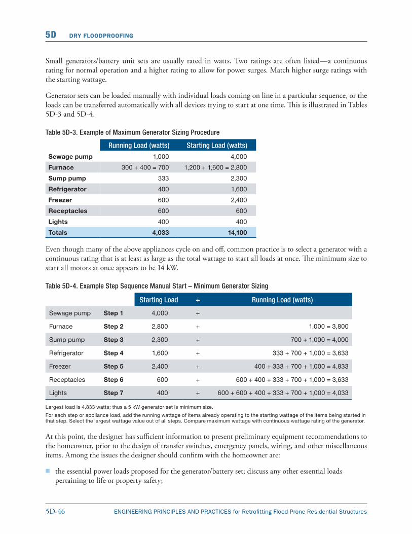
5D-46 ENGINEERING PRINCIPLES AND PRACTICES for Retrofitting Flood-Prone Residential Structures
5D DRY FLOODPROOFING
Small generators/battery unit sets are usually rated in watts. Two ratings are often listed—a continuous rating for normal operation and a higher rating to allow for power surges. Match higher surge ratings with the starting wattage.
Generator sets can be loaded manually with individual loads coming on line in a particular sequence, or the loads can be transferred automatically with all devices trying to start at one time. This is illustrated in Tables 5D-3 and 5D-4.
Table 5D-3. Example of Maximum Generator Sizing Procedure
Running Load (watts) Starting Load (watts)
Sewage pump 1,000 4,000
Furnace 300 + 400 = 700 1,200 + 1,600 = 2,800
Sump pump 333 2,300
Refrigerator 400 1,600
Freezer 600 2,400
Receptacles 600 600
Lights 400 400
Totals 4,033 14,100
Even though many of the above appliances cycle on and off, common practice is to select a generator with a continuous rating that is at least as large as the total wattage to start all loads at once. The minimum size to start all motors at once appears to be 14 kW.
Table 5D-4. Example Step Sequence Manual Start – Minimum Generator Sizing
Starting Load + Running Load (watts)
Sewage pump Step 1 4,000 +
Furnace Step 2 2,800 + 1,000 = 3,800
Sump pump Step 3 2,300 + 700 + 1,000 = 4,000
Refrigerator Step 4 1,600 + 333 + 700 + 1,000 = 3,633
Freezer Step 5 2,400 + 400 + 333 + 700 + 1,000 = 4,833
Receptacles Step 6 600 + 600 + 400 + 333 + 700 + 1,000 = 3,633
Lights Step 7 400 + 600 + 600 + 400 + 333 + 700 + 1,000 = 4,033
Largest load is 4,833 watts; thus a 5 kW generator set is minimum size.
For each step or appliance load, add the running wattage of items already operating to the starting wattage of the items being started in that step. Select the largest wattage value out of all steps. Compare maximum wattage with continuous wattage rating of the generator.
At this point, the designer has sufficient information to present preliminary equipment recommendations to the homeowner, prior to the design of transfer switches, emergency panels, wiring, and other miscellaneous items. Among the issues the designer should confirm with the homeowner are:
� the essential power loads proposed for the generator/battery set; discuss any other essential loads pertaining to life or property safety;
5D-47ENGINEERING PRINCIPLES AND PRACTICES for Retrofitting Flood-Prone Residential Structures
DRY FLOODPROOFING 5D
� generator/battery set siting and proposed location; this should be discussed in light of unit weight, portage, storage, and handling methods; and
� provisions for fuel storage and fuel storage safety.
The designer should also:
� educate the homeowner on battery operating time and/or generator operating time vs. fuel tank capacity;
� present initial generator/battery set cost and future operating costs;
� discuss requirements for having equipment located above the FPE; and
� discuss generator heat radiation and exhaust precautions to prevent carbon monoxide poisoning.
Step 5: Select transfer switch size.
Transfer switches are designed to transfer emergency loads from the main house system to the generator/battery system in the event of a power failure. After power has been restored, the transfer switch is used to transfer power from the generator/battery set to the house system. Transfer switches can be manual or automatic. It is important to check with local code officials regarding requirements for how transfer switches are set up.
Manual transfer switches generally have the following characteristics:
� double-pole, double-throw, nonfusible, safety switch, general duty with factory installed solid neutral, and ground bus. Double-pole, double-throw transfer switch es are typically required to prevent accidentally feeding power back into the utility lines to workers servicing the line. This switch also protects the generator set from damage when the power is restored;
� transfer switches are available with National Electrical Manufacturers Association (NEMA) 1 enclosures for indoor mounting and NEMA 3R enclosures for outdoor locations;
� the voltage rating of transfer switches is typically 250 volts; and
� available sizes are 30 amp, 60 amp, 100 amp, and 200 amp.
The designer should consider the following items when selecting a manual transfer switch:
� coordinate amperage to match emergency panel rating, continuous current rating of branch circuits, genset over current protection, and panel branch feeder circuit breaker size;
� fusible manual transfer switches are required as service entrance equipment and are required if the panel circuit breaker size does not correspond to the emergency panel size and generator/battery set circuit breaker size;
� several manufacturer models are not load break rated and require load shedding before transfer operation; these switches must be used for isolation only—they do not have quick make-quick break operation;
5D-48 ENGINEERING PRINCIPLES AND PRACTICES for Retrofitting Flood-Prone Residential Structures
5D DRY FLOODPROOFING
� some transfer switches are “lock out” capable in the “off” position;
� switches should have door interlocks to prevent the door from opening with the handle in the “on” position and
� avoid locating the transfer switch at a meter or service entrance outdoor location. Switches are not service entrance rated unless they are fusible and, with this scenario the total house load is transferred to the genset. This method requires a much larger switch and cannot be taken out of service without de-energizing the entire dwelling.
Automatic transfer switches are much more expensive than manual transfer switches and require an electrical start option for the generator/battery set. These switches are usually not cost-effective for homeowner generator/battery set installations, but may in certain applications involving life safety issues, warrant the added expense.
Automatic transfer switches automatically start the generator/battery set upon loss of regular power and transfer the emergency load to the generator/battery source. After power has been restored for some time, the transfer switch automatically transfers back to normal power source. The generator set continues to run for some time unloaded until the set has cooled down and then it shuts off. The designer should contact the manufacturers for specific applications data for these automatic transfer switch devices.
Step 6: Select emergency panel size.
Equipment and appliances that need to be powered by a generator/battery set are typically wired in an emergency panel box. The design of the emergency panel box should be conducted with the following considerations in mind:
� select branch circuit loads for emergency operation;
� size branch circuit over current devices in emergency panel to protect equipment and conductor feeding equipment; appliance circuits and motor loads should be sized in accordance with NEC requirements;
� size panel bus based upon NEC requirements and on continuous rating at 125 percent calculated load for items that could operate over 3 hours;
� verify panel box size vs. number and size of circuit breakers; and
� see Tables 5D-5 and 5D-6 for minimum panel bus sizes and emergency panel specification criteria.
Table 5D-5. Minimum Panel Bus Sizes
Ampacity Pole Spaces
30 2
70 2
100 8
125 12–24
5D-49ENGINEERING PRINCIPLES AND PRACTICES for Retrofitting Flood-Prone Residential Structures
DRY FLOODPROOFING 5D
Table 5D-6. Emergency Panel Specification Criteria
Load center type residential panel
Main lug
Indoor NEMA 1 enclosure above flood protection level with isolated neutral for sub panel application
Same short circuit current rating as main panel with ground bar kit
Pole spaces as required for appliance and motor circuit breakers
At this point, the designer should confirm several items with the homeowner including:
� emergency panel location above flood protection level;
� transfer switch location above flood protection level; and
� no load transfer switch operation.
Step 7: Design wire conductor and raceway ground system.
Select route for wiring between panel, transfer switch, and generator set and specific wiring materials in accordance with local electric codes or NEC.
Operations and Maintenance Issues: The following instructions should be provided to the homeowner with generator equipment.
For manual start generators, operating procedures include:
1. Turn off or disconnect all electrical equipment, including essential equipment in emergency panel. CAUTION: Make sure solid state appliances remain off while standby power is operating.
2. Connect generator to receptacle.
3. Place transfer switch in generator position.
4. Start generator and bring it up to proper speed (1,800 revolutions per minute [rpm] or 3,600 rpm). Check generator volt meter; it should read 115-125 volts; the frequency meter should read 60 hertz plus or minus three hertz.
5. Start the motors and equipment individually, letting the genset return to normal engine speed after each load has been applied. The load should be applied in the sequence used to determine the genset size and generally with the largest motor load applied first. If the generator cuts out, turn off all the electrical equipment and restart.
6. Check the volt meter frequently. If it falls below 200 volts for 240-volt equipment or 100 volts for 120-volt equipment, reduce the load by turning off some equipment.
7. When normal power has been restored, turn off all the electrical equipment slowly, one load at a time. Turn off all emergency loads, place transfer switch in normal load position, and turn electrical equipment back on.
WARNING
If problems occur, turn off existing panel circuit breaker feeding the transfer switch before investigating problems with faulty connections or wiring.
5D-50 ENGINEERING PRINCIPLES AND PRACTICES for Retrofitting Flood-Prone Residential Structures
5D DRY FLOODPROOFING
8. Turn off genset circuit breaker. However, allow genset to run approximately 5 minutes for cool-down. Then turn off generator engine. Return generator to storage location.
For manual start generators, maintenance procedures include:
1. Operate generator at about 50 percent load monthly or bimonthly to ensure reliability.
2. Check for fuel leaks.
3. Change engine oil per manufacturer’s requirements.
4. Replace or use the fuel supply about every 30 to 45 days to prevent moisture condensation in the tank and fuel breakdown. Gasoline additives can keep gasoline-powered generator fuel from breaking down.
5. Keep tank full.
6. Replace air filter element per manufacturer’s requirements.
5D.11.3 Construction
All wiring shall be installed by licensed electricians to meet NEC requirements, local electrical regulations, and requirements of the local power company. Bond ground from generator emergency panel through transfer switch back to main service panel.
5D.12 Non-Residential ConstructionDry floodproofing can also be used with varying degrees of success on non-residential engineered buildings. The general concepts for dry floodproofing are the same for any structure. The application of the concepts can vary as to the size and nature of the building and its use. Due to the more robust nature of the construction, the more thorough examination of load path, and more rigorous inspection cycle, non-residential engineered buildings are more likely to have success in managing the overloads that occur with flood conditions. Extreme caution is still required to avoid the unintended consequences of creating more damage than was thought to have been avoided by the flood. Structural failure issues must be examined closely.
Options available to non-residential engineered construction are:
� permanent closure of non-essential vulnerable openings;
� watertight core areas;
� enhanced flood shields; and
� pressure relief systems to balance protect against structural failure (similar to wet floodproofing).
5D.12.1 Permanent Closure of Openings
For instance, an owner may be able to permanently close some vulnerable openings lower in the structure (window wells and coal chutes) on non-residential structures that are not required for safety egress; this
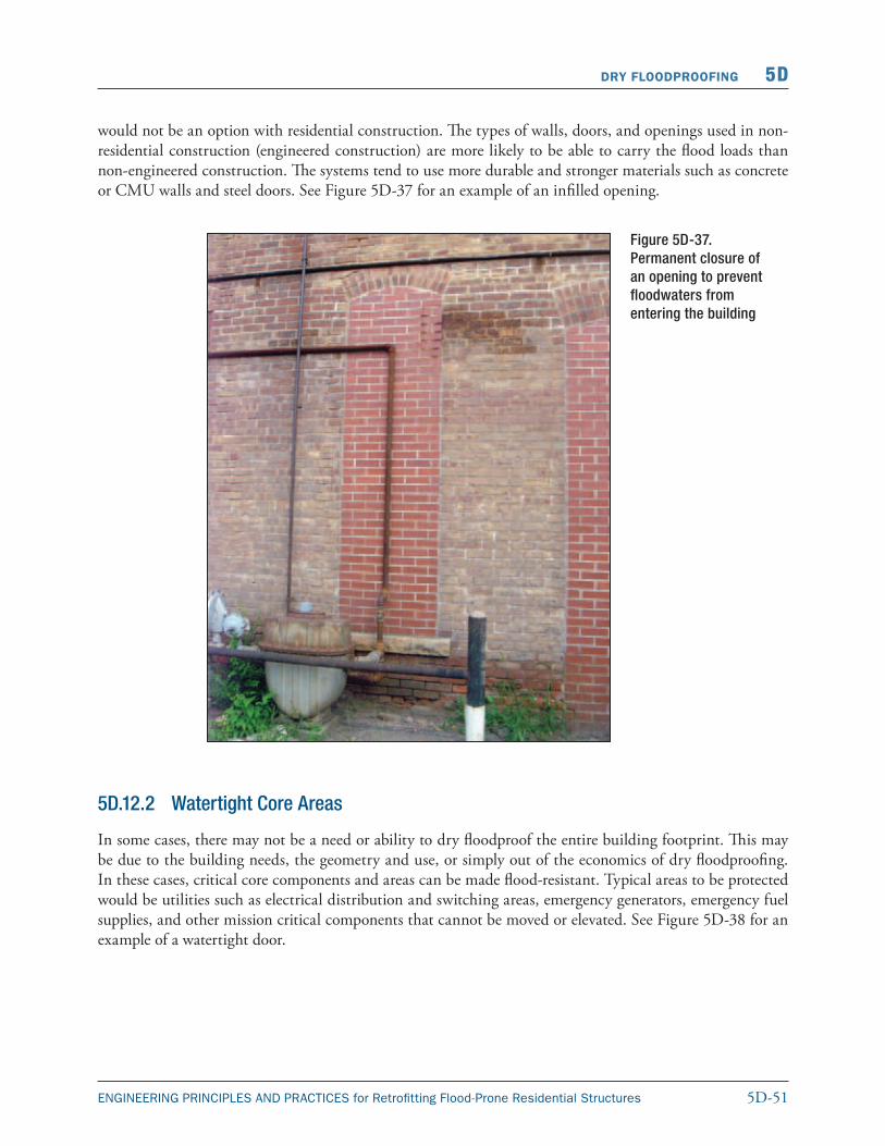
5D-51ENGINEERING PRINCIPLES AND PRACTICES for Retrofitting Flood-Prone Residential Structures
DRY FLOODPROOFING 5D
would not be an option with residential construction. The types of walls, doors, and openings used in non-residential construction (engineered construction) are more likely to be able to carry the flood loads than non-engineered construction. The systems tend to use more durable and stronger materials such as concrete or CMU walls and steel doors. See Figure 5D-37 for an example of an infilled opening.
Figure 5D-37. Permanent closure of an opening to prevent floodwaters from entering the building
5D.12.2 Watertight Core Areas
In some cases, there may not be a need or ability to dry floodproof the entire building footprint. This may be due to the building needs, the geometry and use, or simply out of the economics of dry floodproofing. In these cases, critical core components and areas can be made flood-resistant. Typical areas to be protected would be utilities such as electrical distribution and switching areas, emergency generators, emergency fuel supplies, and other mission critical components that cannot be moved or elevated. See Figure 5D-38 for an example of a watertight door.
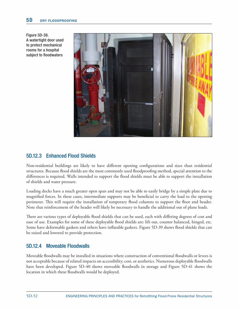
5D-52 ENGINEERING PRINCIPLES AND PRACTICES for Retrofitting Flood-Prone Residential Structures
5D DRY FLOODPROOFING
Figure 5D-38. A watertight door used to protect mechanical rooms for a hospital subject to floodwaters
5D.12.3 Enhanced Flood Shields
Non-residential buildings are likely to have different opening configurations and sizes than residential structures. Because flood shields are the most commonly used floodproofing method, special attention to the differences is required. Walls intended to support the flood shields must be able to support the installation of shields and water pressure.
Loading docks have a much greater open span and may not be able to easily bridge by a simple plate due to magnified forces. In these cases, intermediate supports may be beneficial to carry the load to the opening perimeter. This will require the installation of temporary flood columns to support the floor and header. Note that reinforcement of the header will likely be necessary to handle the additional out of plane loads.
There are various types of deployable flood shields that can be used, each with differing degrees of cost and ease of use. Examples for some of these deployable flood shields are: lift out, counter balanced, hinged, etc. Some have deformable gaskets and others have inflatable gaskets. Figure 5D-39 shows flood shields that can be raised and lowered to provide protection.
Moveable floodwalls may be installed in situations where construction of conventional floodwalls or levees is not acceptable because of related impacts on accessibility, cost, or aesthetics. Numerous deployable floodwalls have been developed. Figure 5D-40 shows moveable floodwalls in storage and Figure 5D-41 shows the location in which these floodwalls would be deployed.
5D.12.4 Moveable Floodwalls
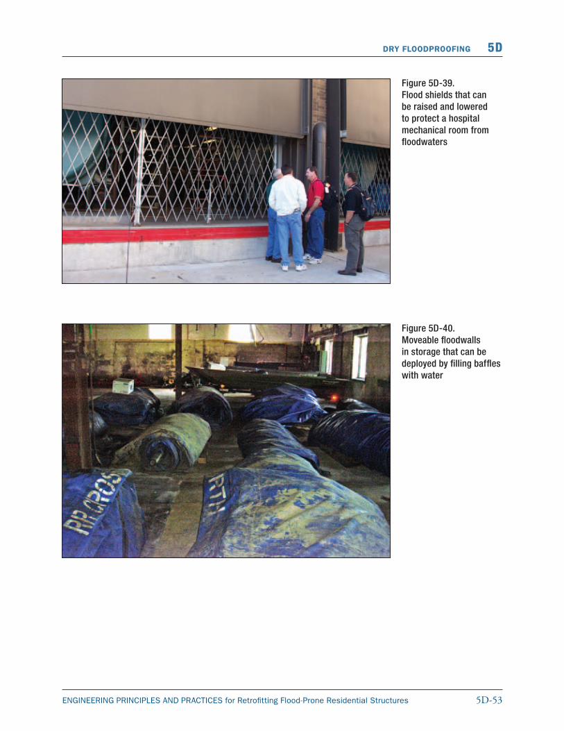
5D-53ENGINEERING PRINCIPLES AND PRACTICES for Retrofitting Flood-Prone Residential Structures
DRY FLOODPROOFING 5D
Figure 5D-39. Flood shields that can be raised and lowered to protect a hospital mechanical room from floodwaters
Figure 5D-40. Moveable floodwalls in storage that can be deployed by filling baffles with water
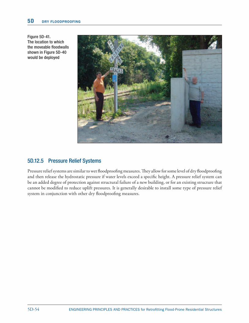
5D-54 ENGINEERING PRINCIPLES AND PRACTICES for Retrofitting Flood-Prone Residential Structures
5D DRY FLOODPROOFING
Figure 5D-41. The location to which the moveable floodwalls shown in Figure 5D-40 would be deployed
5D.12.5 Pressure Relief Systems
Pressure relief systems are similar to wet floodproofing measures. They allow for some level of dry floodproofing and then release the hydrostatic pressure if water levels exceed a specific height. A pressure relief system can be an added degree of protection against structural failure of a new building, or for an existing structure that cannot be modified to reduce uplift pressures. It is generally desirable to install some type of pressure relief system in conjunction with other dry floodproofing measures.


![PRINCIPLES, PRACTICES, AND SOCIAL MOVEMENTS · 2006] PRINCIPLES, PRACTICES, AND SOCIAL MOVEMENTS 931 practices. Yet, even though principles like the anticlassification prin-ciple](https://img.pdfslide.net/doc/110x75/5ebe1b38c94693584f0b4160/principles-practices-and-social-movements-2006-principles-practices-and-social.jpg)