Embed Size (px)
Citation preview
IPS-E-CE-130
This Standard is the property of Iranian Ministry of Petroleum. All rights are reserved to the owner. Neither whole nor any part of this document may be disclosed to any third party, reproduced, stored in any retrieval system or transmitted in any form or by any means without the prior written consent of the Iranian Ministry of Petroleum.
ENGINEERING STANDARD
FOR
PILES
ORIGINAL EDITION
JAN. 1996
This standard specification is reviewed and updated by the relevant technical committee on Nov. 1997(1) and Oct. 2004(2). The approved modifications are included in the present issue of IPS.
Jan. 1996
IPS-E-CE-130
1
CONTENTS : PAGE No.
1. SCOPE ............................................................................................................................................ 2
2. REFERENCES ................................................................................................................................ 2
3. NOMENCLATURE .......................................................................................................................... 4
4. UNITS .............................................................................................................................................. 4
5. PRIOR TO PILING: FOUNDATION INVESTIGATION................................................................... 4
6. GENERAL REQUIREMENTS FOR PILING ................................................................................... 5
7. STEEL PILES.................................................................................................................................. 8
7.1 General ..................................................................................................................................... 8
7.2 Materials................................................................................................................................... 9
7.3 Design Requirements ........................................................................................................... 10
8. CAST-IN-PLACE CONCRETE PILES.......................................................................................... 11
8.1 General ................................................................................................................................... 11
8.2 Drilled or Augered Uncased Piles ....................................................................................... 12
8.3 Driven Uncased Piles............................................................................................................ 12
8.4 Enlarged Base Piles.............................................................................................................. 13
8.5 Steel Cased Piles .................................................................................................................. 13
9. PRECAST CONCRETE PILES..................................................................................................... 14
9.1 General ................................................................................................................................... 14
9.2 Reinforced Piles .................................................................................................................... 14
9.3 Prestressed Concrete Piles ................................................................................................. 15
10. TIMBER (WOODEN) PILES ....................................................................................................... 15
11. COMPOSITE PILES.................................................................................................................... 17
12. CAISSON PILES......................................................................................................................... 17
APPENDICES:
APPENDIX A CHOICE OF PILES ............................................................................................... 19
APPENDIX B TYPICAL PILE CHARACTERISTICS AND USES............................................... 22

Jan. 1996
IPS-E-CE-130
2
1. SCOPE
This Engineering Standard provides basic requirements governing the design and the selection of piling materials for land and marine construction. It applies to structural steel, steel pipe (plain or filled with concrete), cast-in-place concrete, precast concrete, timber, composite and caisson type piles.
Where necessary, guidance for the protection of steel piles and preservance of timber piles has been provided.
This Standard does not cover sheet piling. For the design requirements of sheet piling, reference is made to IPS-E-CE- 140 "Retaining Walls".
Throughout this Standard, the symbol AR denotes Authorized Representative of the Owner.
Note 1:
This standard specification is reviewed and updated by the relevant technical committee on Nov. 1997. The approved modifications by T.C. were sent to IPS users as amendment No. 2 by circular No 13 on Nov. 1997. These modifications are included in the present issue of IPS.
Note 2:
This standard specification is reviewed and updated by the relevant technical committee on Oct. 2004. The approved modifications by T.C. were sent to IPS users as amendment No. 2 by circular No 251 on Oct. 2004. These modifications are included in the present issue of IPS.
2. REFERENCES
Throughout this Standard the following dated and undated standards/codes are referred to. These referenced documents shall, to the extent specified herein, form a part of this standard. For dated references, the edition cited applies. The applicability of changes in dated references that occur after the cited date shall be mutually agreed upon by the company and the vendor. For undated references, the latest edition of the referenced documents (including any supplements and amendments) applies.
ACI STANDARD (AMERICAN CONCRETE INSTITUTE)
318 "Building Code Requirements for Reinforced Concrete"
543 R 2000 "Design, Manufacture and Installation of Concrete Piles"
AISC SPECIFICATION (AMERICAN INSTITUTE FOR STEEL CONSTRUCTION)
"Specification for the Design, Fabrication, and Erection of Structural Steel for Buildings"
API STANDARD (AMERICAN PETROLEUM INSTITUTE)
API 5L 2000 "Specification for Line Pipe"
ASTM STANDARDS (AMERICAN SOCIETY FOR TESTING AND MATERIALS)
A 36 "Specification for Structural Steel"
A 252 "Specification for Welded and Seamless Steel Pipe Piles"
A 283 "Specification for Low and Intermediate Tensile Strength Carbon
Jan. 1996
IPS-E-CE-130
3
Steel Plates"
A 416 "Specification for Uncoated Seven-wire Stress-relieved Steel Strand for Prestressed Concrete"
A 572/A 572M "Standard Specification for High-Strength Low-Alloy Columbium-Vanadium Structural Steel"
A 633/A 633M "Standard Specification for Normalized High-Strength Low-Alloy Structural Steel Plates"
C 150 Rev. A "Specification for Portland Cement"
D 25 "Specification for Round Timber Piles"
D 2899 "Establishing Design / Stresses for Round Timber Piles"
D 1143 "Standard Test Method for Piles under Static Axial Compressive Load"
D 3689 "Standard Test Method for Individual Piles Under Static Axial Tensile Load"
AWPA STANDARD (AMERICANWATERANDPOWERASSOCIATION)
C 3 "Piles-Preservative Treatment by Pressure Processes"
M 4 "Care of Preservative-Treated Wood Products"
AWS (AMERICAN WELDING SOCIETY)
D 1.1/D 1.1 M 2002 "Structural Welding Code"
BSI (BRITISH STANDARDS INSTITUTION)
BS 5896:1980 "Steel Wire for Prestressed Concrete"
BS 8004 1996 "Code of Practice for Foundation"
IPS (IRANIAN PETROLEUM STANDARDS)
IPS-E-GN-100 "Engineering Standard for Units"
IPS-E-CE-140 "Engineering Standard for Retaining Walls & Slope Protection"
IPS-E-CE-200 "Engineering Standard for Concrete Structure"
IPS-E-CE-210 "Engineering Standard for Steel Structures"
IPS-E-CE-500 "Engineering Standard for Loads"
IPS-C-TP-101 "Construction Standard for Surface Preparation"
SSPC SPECIFICATION
SP 5 "White Metal Blast Cleaning"
UNIFORM BUILDING CODE
UBC-88 "Section 2908: Piles-General Requirements"
"Section 2909: Specific Pile Requirements"
Jan. 1996
IPS-E-CE-130
4
3. SYMBOLS
Throughout this Standard, the following symbols are used:
Fy or fy = specified yield strength of reinforcement in MPa.
fc = specified compression strength of concrete in MPa.
4. UNITS
International System of Units (SI) in accordance with IPS-E-GN-100 shall be used.
5. PRIOR TO PILING: FOUNDATION INVESTIGATION
5.1 General
The classification of the soil at each site shall be determined by a recognized soil engineering laboratory.
5.2 Investigation
The classification shall be based on observation and any necessary tests of the materials disclosed by borings or excavations made in appropriate locations. Additional studies may be necessary to evaluate soil strength, the effect of moisture variation on soil-bearing capacity, compressibility and expansiveness.
5.3 Reports
The soil classification and design bearing capacity shall be shown on the plans. The AR shall require submission of a written report of the investigation which shall include, but need not be limited to, the following information:
a) A plot showing the location of all test borings and/or excavations.
b) Descriptions and classifications of the materials encountered.
c) Elevation of the water table, if encountered.
d) Recommendations for foundation type and design criteria including bearing capacity, provisions to minimize
the effects of expansive soils and the effects of adjacent loads.
e) Expected total and differential settlement. (See also Sub-clause 6.1)
5.4 Expansive Soils
When expansive soils are present, the AR may require that special provisions be made in the foundation design and construction to safeguard against damage due to this expansiveness. He may require a special investigation and report to provide this design and construction criteria.
5.5 Adjacent Loads
Where footings are placed at varying elevations the effect of adjacent loads shall be included in the foundation design.
5.6 Drainage
Provisions shall be made for the control and drainage of surface water around structures.
Jan. 1996
IPS-E-CE-130
5
5.7 Plans and Drawings
5.7.1 Piling plans
The piling shall be based on calculations and data as specified in IPS-E-CE-500: "Loads".
5.7.2 Piling drawings
The drawing shall include:
-The location of all piles, whereby raking piles, if any, shall be clearly indicated with reference level(s) for setting out.
-The required minimum ultimate bearing capacity(ies) of the piles.
-The required minimum penetration depth(s) and, if the characteristics of piles and the driving equipment are known, the minimum number of blows of the hammer per 300 mm penetration.
-General notes and reference drawings, and cut-off levels of the piles.
6. GENERAL REQUIREMENTS FOR PILING
6.1 General
Pile foundations shall be designed and installed on the basis of a foundation investigation as defined in Clause 5.
The investigation and report provisions of Clause 5 shall be expanded to include but not be limited to the following:
a) Recommended pile types and installed capacities. For additional information concerning choice of piles, see Appendix A and section 7 BS 8004-1996, and for typical pile characteristics and uses, see Table B-1 of Appendix B.
b) Driving criteria.
c) Installation and field inspection procedures.
d) Pile load test requirements.
e) Durability of pile materials.
f) Designation of bearing stratum or strata.
g) Field inspection and reporting procedures
6.2 Interconnection
Individual pile caps and caissons of every structure subjected to seismic forces shall be interconnected by ties. Such ties shall be capable of resisting, in tension or compression, a minimum horizontal force equal to 10 percent of the larger column vertical load.
6.3 Column Action
All piles standing unbraced in air, water or material not capable of lateral support, shall conform with the applicable column formula as specified in Concrete Structures, and Steel Structures.
Such piles driven into firm ground may be considered fixed and laterally supported at 1.5 meter below the ground surface and in soft material at 3 meters below the ground surface unless otherwise prescribed by the AR after a foundation investigation by an approved soil engineering laboratory.
Jan. 1996
IPS-E-CE-130
6
6.4 Group Action
The bearing capacity of a pile group consisting of end bearing piles or piles driven into granular strata at normal spacing may be considered at least equal to the sum of the bearing capacities of the individual piles. The bearing capacity of a friction pile group in cohesive soil should be checked by evaluating the shear strength and bearing capacity of the soil and by considering that the pile group is supported by shear on the periphery of the group and by end bearing on the base area of the group. The use of group reduction formulas based on spacing and number of piles is not recommended.
6.5 Jetting
Jetting shall not be used except where and as specifically permitted by the AR. When used, jetting shall be carried out in such a manner that the carrying capacity of existing piles and structures shall not be impaired. After withdrawal of the jet, piles shall be driven down until the required resistance is obtained.
All piles placed with the aid of jets shall be firmly seated by driving with a hammer without jetting, until at least an additional 1.5 m of penetration is secured, or until refusal is reached.
Acceptable procedures for water-jetting are as follows:
a) A minimum of two water jet pipes placed symmetrically about the pile and operated simultaneously.
b) If approved by AR, a method entailing water jet pipe encased in the pile may be used.
6.6 Protection of Pile Materials
Where the boring records of site conditions indicate possible deleterious action on pile materials because of soil constituents, changing water levels or other factors, such materials shall be adequately protected by methods or processes approved by the AR.
The effectiveness of such methods or processes for the particular purpose shall have been thoroughly established by satisfactory service records or other evidence which demonstrates the effectiveness of such protective measures.
6.7 Pile Caps
Pile caps shall be of reinforced concrete. The soil immediately below the pile cap shall not be considered as carrying any vertical load. The tops of all piles shall be embedded not less than 75 mm into pile caps and the caps shall extend at least 100 mm beyond the edges of all piles. The tops of all piles shall be cut back to sound material before capping.
6.8 Allowable Pile Loads
6.8.1 Determination of allowable loads
The allowable axial and lateral loads on piles shall be determined by an approved formula, load tests or method of analysis.
6.8.2 Piles in subsiding areas
Where piles are driven through subsiding fills or other subsiding strata and derive support from underlying firmer materials, the downward frictional forces which are imposed on piles by the subsiding upper strata shall be included in the design.
Jan. 1996
IPS-E-CE-130
7
6.8.3 Driving formula
The allowable compressive load on any pile when determined by the application of an approved driving formula shall not exceed 36 metric tons. The formula load shall be determined for gravity-drop or power-actuated hammers and the hammer energy used shall be the maximum consistent with the size, strength and weight of the driven piles. The use of a follower shall be permitted only with the approval of the AR. The introduction of fresh hammer cushion or pile cushion material just prior to final penetration shall not be permitted.
6.8.4 Load tests
When greater compressive loads per pile than permitted by sub-clause 6.8.3 are desired or when the design load for any pile foundation is in doubt, control test piles shall be tested in accordance with ASTM D 1143. At least one pile shall be test loaded in each area of uniform subsoil conditions.
In subsequent driving of the balance of foundation piles, all piles shall be deemed to have a supporting capacity equal to the control pile when such piles are of the same type, size and relative length as the test pile, are installed using the same or comparable methods and equipment as the test pile, are installed in similar subsoil conditions as the test pile and when the rate of penetration of such piles is equal to or less than that of the test pile through a comparable driving distance.
6.8.5 Allowable lateral load
When required by the design, the lateral load capacity of a single pile or a pile group shall be determined by an approved method of analysis or by lateral load tests to at least twice the proposed design working load. The resulting allowable load shall be not more than one-half of that test load which produces a gross lateral movement of 25 mm at the ground surface.
6.8.6 Batter or raking piles
When large lateral loads are to be resisted by a pile group, it is recommended to consider the use of piles driven at a slope with the vertical, i.e. batter or raking piles. For the purpose of design, batter piles are assumed to carry all lateral loads.
When batter piles are used together with vertical piles, the design of the foundation structure should consider that the batter piles will accept a portion of the vertical load. The inclination and position of the batter piling should be selected such that when a lateral load is applied, the resultant of the lateral and vertical loadings is axial and the effects of bending moments are kept to a minimum.
The acceptable range for pile batters is from 1 horizontal to 12 vertical
( ) to a batter of 5 to 12 ( ). It should be noted that in case the batter exceeds 1 to 4 ( ), the driving may require special equipment with the resulting increased cost.
6.8.7 Uplift capacity
When required by the design, the uplift capacity of a single pile shall be determined in accordance with ASTM D 3689 or an approved method of analysis based upon a minimum factor of safety of three. The maximum allowable uplift load shall be one-half that load which produces an upward movement of the pile but equal to the gross elastic extension of the pile plus 2.54 mm. For pile groups subjected to uplift, the allowable working uplift load for the group shall be the lesser of:
a) The proposed individual pile uplift working load times the number of piles in the group, or
b) Two-thirds of the effective weight of the pile group and the soil contained within a block defined by the perimeter of the group and the length of the pile.
Jan. 1996
IPS-E-CE-130
8
6.8.8 Bearing capacity
Individual piles and groups of piles shall develop ultimate load capacities of at least twice the design working loads in the designated bearing layers. Analysis shall show that no soil layer underlying the designated bearing layers causes the bearing capacity safety factor to be less than two.
6.8.9 Bent piles
The load carrying capacity of piles discovered to have a sharp or sweeping bend may be determined by an approved method of analysis or by load testing a representative pile.
6.8.10 Overloads on piles
The maximum compressive load on any pile due to mislocation shall not exceed 110% of the allowable design load.
6.9 Pile Spacing
A general rule for minimum pile spacing is 3 times the average diameter for round or octagonal piles and 3 times the diagonal dimension of square piles. However regardless of pile size, a minimum distance between piles is usually specified. Spacing is measured from center to center of the piles.
For more information see section 2.1.4 ACI 543R-2000.
Several factors should be considered in establishing the pile spacing. For example, the following considerations might require an increase in the normal pile spacing:
a) For piles deriving their principal support by friction.
b) For extremely long piles, especially if they are flexible in order to minimize tip interference.
c) For uncased cast-in-place concrete piles where pile driving could damage adjacent unset concrete shafts
d) For piles carrying very high loads.
e) For piles that are driven in obstructed ground.
f) Where group capacity governs.
g) Where passive soil pressures are considered a major factor in developing pile lateral load capacity.
h) Where excessive ground heave conditions exist.
Special installation methods could be used as an alternative to increasing pile spacing. For example, predrilling for cases (b), (e), and (h) above; or staggered driving sequence for case (c). Closer than normal spacing might be permitted for end bearing piles installed in predrilled holes.
Under special conditions, the pile spacing might be determined by the available area for the required number of piles.
7. STEEL PILES
7.1 General
This Clause gives guidance on the selection of material and engineering design for structural steel piles, steel pipe piles and concrete-filled steel pipe piles.
Jan. 1996
IPS-E-CE-130
9
7.2 Materials
7.2.1 Structural steel piles
Structural steel piles shall consist of rolled H-sections in accordance with ASTM-A 36.
7.2.2 Steel pipe piles
Steel pipe piles shall be per ASTM A 252 Gr 2 or 3, API 5L Gr B. and the following:
a) Strength of welds (shop and field) including the type of joint preparation and percent penetration shall be developed for the specific application and submitted to the AR for approval. Welding procedure and welder qualification shall be per AWS D1.1.
b) Complete penetration welds are required for all piles which will be subjected to tensile or flexural stresses.
c) Pipe smaller than 200 mm NPS shall not be used.
d) A minimum corrosion allowance of 1.5 mm shall be added to the calculated wall thickness.
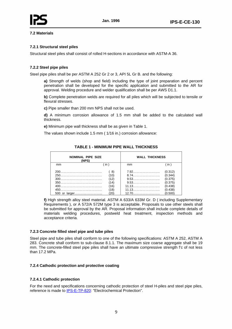
e) Minimum pipe wall thickness shall be as given in Table 1.
The values shown include 1.5 mm ( 1/16 in.) corrosion allowance:
TABLE 1 - MINIMUM PIPE WALL THICKNESS
NOMINAL PIPE SIZE (NPS)
WALL THICKNESS
mm ( in ) 200…………………………………. ( 8) 250…………………………………. (10) 300…………………………………. (12) 350…………………………………. (14) 400…………………………………. (16) 450…………………………………. (18) 500 or larger……………………... (20)
mm ( in ) 7.92…………………….. (0.312) 8.74…………………….. (0.344) 9.53…………………….. (0.375) 9.53…………………….. (0.375) 11.13…………………….. (0.438) 11.13…………………….. (0.438) 12.70…………………….. (0.500)
f) High strength alloy steel material. ASTM A 633/A 633M Gr. D ( including Supplementary Requirements ), or A 572/A 572M type 3 is acceptable. Proposals to use other steels shall be submitted for approval by the AR. Proposal information shall include complete details of materials welding procedures, postweld heat treatment, inspection methods and acceptance criteria.
7.2.3 Concrete filled steel pipe and tube piles
Steel pipe and tube piles shall conform to one of the following specifications: ASTM A 252, ASTM A 283. Concrete shall conform to sub-clause 8.1.1. The maximum size coarse aggregate shall be 19 mm. The concrete-filled steel pipe piles shall have an ultimate compressive strength f’c of not less than 17.2 MPa.
7.2.4 Cathodic protection and protective coating
7.2.4.1 Cathodic protection
For the need and specifications concerning cathodic protection of steel H-piles and steel pipe piles, reference is made to IPS-E-TP-820: "Electrochemical Protection".
Jan. 1996
IPS-E-CE-130
10
7.2.4.2 Protective coatings
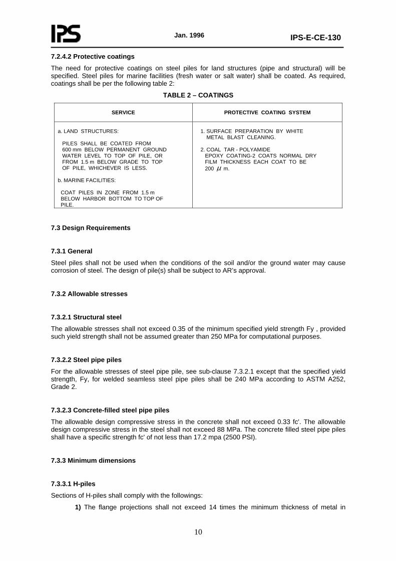
The need for protective coatings on steel piles for land structures (pipe and structural) will be specified. Steel piles for marine facilities (fresh water or salt water) shall be coated. As required, coatings shall be per the following table 2:
TABLE 2 – COATINGS
SERVICE
PROTECTIVE COATING SYSTEM
a. LAND STRUCTURES: PILES SHALL BE COATED FROM 600 mm BELOW PERMANENT GROUND WATER LEVEL TO TOP OF PILE, OR FROM 1.5 m BELOW GRADE TO TOP OF PILE, WHICHEVER IS LESS. b. MARINE FACILITIES: COAT PILES IN ZONE FROM 1.5 m BELOW HARBOR BOTTOM TO TOP OF PILE.
1. SURFACE PREPARATION BY WHITE METAL BLAST CLEANING. 2. COAL TAR - POLYAMIDE EPOXY COATING-2 COATS NORMAL DRY FILM THICKNESS EACH COAT TO BE 200 μ m.
7.3 Design Requirements
7.3.1 General
Steel piles shall not be used when the conditions of the soil and/or the ground water may cause corrosion of steel. The design of pile(s) shall be subject to AR’s approval.
7.3.2 Allowable stresses
7.3.2.1 Structural steel
The allowable stresses shall not exceed 0.35 of the minimum specified yield strength Fy , provided such yield strength shall not be assumed greater than 250 MPa for computational purposes.
7.3.2.2 Steel pipe piles
For the allowable stresses of steel pipe pile, see sub-clause 7.3.2.1 except that the specified yield strength, Fy, for welded seamless steel pipe piles shall be 240 MPa according to ASTM A252, Grade 2.
7.3.2.3 Concrete-filled steel pipe piles
The allowable design compressive stress in the concrete shall not exceed 0.33 fc'. The allowable design compressive stress in the steel shall not exceed 88 MPa. The concrete filled steel pipe piles shall have a specific strength fc' of not less than 17.2 mpa (2500 PSI).
7.3.3 Minimum dimensions
7.3.3.1 H-piles
Sections of H-piles shall comply with the followings:
1) The flange projections shall not exceed 14 times the minimum thickness of metal in
Jan. 1996
IPS-E-CE-130
11
either the flange or the web and the flange widths shall be not less than 80% of the depth of the section.
2) The nominal depth in the direction of the web shall be not less than 200 mm.
3) Flanges and web shall have a minimum nominal thickness of 9.5 mm.
7.3.3.2 Steel pipe piles
Steel pipe piles driven open ended shall have a nominal outside diameter of not less than 250 mm and a minimum wall thickness of 6.4 mm for diameters less than 350 mm and a minimum wall thickness of 9.5 mm for diameters 350 mm and over. Pipe of less wall thickness may be driven open ended if a suitable cutting shoe is provided.
7.3.3.3 Concrete-filled steel pipe piles
Piles shall have a nominal outside diameter of not less than 200 mm and a minimum wall thickness in accordance with sub-clause 7.3.3.2 except that for mandrel driven pipe piles the minimum wall thickness may be 2.5 mm.
Reinforcement steel shall conform to sub-clause 8.1.2 . Reinforcement shall not be placed within 25 mm of the steel casing.
8. CAST-IN-PLACE CONCRETE PILES
8.1 General
8.1.1 Material
Concrete piles cast in place against earth in drilled or bored holes shall be made in such a manner as to ensure the exclusion of any foreign matter and to secure a full-sized shaft. The length of such piles shall be limited to not more than 30 times the average diameter.
The selection of type of cast-in-place concrete piles shall be based on competent soil investigations.
When concrete is placed through a funnel hopper at the top of the pile, the concrete mix shall be designed and proportioned so as to produce a cohesive workable mix having a slump of not less than 100 mm and not more than 150 mm. If concrete is to be pumped, the mix design including slump shall be adjusted to produce a pumpable concrete.
Concrete for piles shall have a minimum 28 days compressive strength of 21 MPa. Where soil investigations indicate the likelihood of considerable sulfate attack, consideration shall be given to the use of Type II or Type V Portland Cement as specified in ASTM C 150 Specifications for Portland Cement.
Piles may be either of the permanent or removable steel shell type, may be open or closed end and may be of plain or reinforced concrete.
8.1.2 Reinforcement
Except for steel dowels embedded 1.50 m or less in the pile and as provided in 8.2, reinforcement when required shall be assembled and tied together and shall be placed in the pile as a unit before the reinforced portion of the pile is filled with concrete.
Jan. 1996
IPS-E-CE-130
12
8.2 Drilled or Augered Uncased Piles
8.2.1 Allowable stresses
The allowable design stress in the concrete of drilled uncased piles shall not exceed 0.33 f’c. The allowable design stress in the concrete of augered cast-in-place piles shall not exceed 0.25 f’c.
8.2.2 Dimensions
The pile length shall not exceed 30 times the average diameter. The minimum diameter shall be 300 mm.
Exception:
The length of pile shall be permitted to exceed 30 times the diameter, provided the design and installation of the pile foundation is under the direct supervision of an approved soil engineering laboratory knowledgeable in the field of soil mechanics and pile foundations, which shall certify that the piles as installed satisfy the design criteria.
8.2.3 If concrete is placed by pumping through a hollow-stem auger, the auger shall not be permitted to rotate during withdrawal and shall be withdrawn in a steady continuous motion. Concreting pumping pressures shall be measured and shall be maintained high enough at all times to offset hydrostatic and lateral earth pressures. Concrete volumes shall be measured to insure that the volume of concrete placed in each pile is equal to or greater than the theoretical volume of the hole created by the auger. If the installation process of any pile is interrupted or a loss of concreting pressure occurs, the pile shall be redrilled to original depth and reformed. Augered cast-in-place piles shall not be installed within 6 pile diameters center to center of a pile filled with concrete less than 24 hours old unless approved by the AR. If the concrete ,level in any completed pile drops, the pile shall be rejected and replaced.
8.2.4 Reinforcement
For piles installed with a hollow stem auger, longitudinal steel reinforcement may be placed without lateral ties, provided it is placed through ducts in the auger prior to filling the pile with concrete. All pile reinforcement shall have a concrete cover of not less than 64 mm.
8.3 Driven Uncased Piles
8.3.1 Allowable stress
The allowable design stress in the concrete shall not exceed 0.25 f’c applied to a cross sectional area not greater than the inside area of the drive casing or mandrel.
8.3.2 Dimensions
The pile length shall not exceed 30 times the average diameter. The minimum diameter shall be 300 mm.
8.3.3 Concrete cover
All pile reinforcement shall have a concrete cover of not less than 64 mm measured from the inside face of the drive casing or mandrel.
Jan. 1996
IPS-E-CE-130
13
8.4 Enlarged Base Piles
8.4.1 Materials
Materials for enlarged base piles shall have similar specifications with Sub-clause 8.1.1 of this Standard for cast-inplace concrete piles with the following clarifications:
a) The maximum size for coarse aggregate for all concrete shall be 20 mm.
b) Compacted concrete shall have No slump.*
* No-slump concrete refers to concrete with a consistency corresponding to a slump of 25 mm or less. No-slump concrete is very dry, yet it must be sufficiently workable so that it can be placed and consolidated with the equipment to be used on the job.
8.4.2 Allowable stress
The allowable design compressive stress in the concrete shall not exceed 0.25 f’c except that where the concrete is placed in a permanent steel casing the allowable concrete stress may be increased to 0.33 f’c.
8.4.3 Bearing capacity
Pile bearing capacity shall be verified by load tests in accordance with Sub-clause 6.8.8.
8.4.4 Concrete cover
The minimum concrete cover shall be 60 mm for uncased shafts and 25 mm for cased shafts.
8.5 Steel Cased Piles
8.5.1 Material
Pile shells or casings shall be of steel and shall be sufficiently strong to resist collapse and sufficiently water tight to exclude any foreign materials during the placing of concrete. Steel shells shall have a sealed tip with a diameter of not less than 200 mm.
8.5.2 Allowable stresses
The allowable design compressive stress in the concrete shall not exceed 0.33 f’c except that the allowable concrete stress may be increased to a maximum value of 0.40 f’c for that portion of the pile meeting the following conditions:
1) The thickness of the steel shell is not less than 2.0 mm minimum.
2) The shell is seamless or is provided with seams of strength equal to the basic material and is of a configuration which will provide confinement to the cast in place concrete.
3) The ratio of steel yield strength, fy, to design, f’c, shall be not less than six.
4) The nominal pile diameter is not greater than 400 mm.
8.5.3 Reinforcement
Reinforcement shall not be placed within 25 mm of the steel shell. Reinforcing shall be considered necessary only for unsupported pile lengths or when the pile is designed to resist uplift or unbalanced lateral loads.
Jan. 1996
IPS-E-CE-130
14
9. PRECAST CONCRETE PILES
9.1 General
9.1.1 Design and manufacture
All piles shall be designed and manufactured in accordance with accepted practice and to resist all stresses induced by handling, driving and service loads. The minimum lateral dimension shall be 200 mm. All corners of square piles shall be chamfered. Longitudinal steel shall be arranged in a symmetrical pattern and shall be laterally tied with steel ties or wire spiral spaced not more than 76 mm apart center-to-center for a distance of 600 mm from the ends of the pile and not more than 150 mm elsewhere except that at the ends of each pile the first five ties or spirals shall be spaced 25 mm center to center.
9.2 Reinforced Piles
9.2.1 Design
The minimum amount of longitudinal reinforcement expressed as a percentage of the gross cross-sectional area of the pile shall be 1% for piles 12 m. and shorter and 1 ½% for piles longer than 12 m. and shall consist of at least four bars.
9.2.2 Material
Precast concrete piles shall have a specified compressive strength fc' of not less than 20.68 mpa (3000 PSI) and shall develop a compressive strength of not less than 20.68 mpa (3000 PSI) before driving. Where sub-surface investigations indicate the likelihood of considerable sulfate attack, consideration shall be given to the use of Type II or Type V Portland Cement as specified in ASTM C150-Specifications for Portland Cement.
9.2.3 Allowable stress
The allowable compressive stress in the concrete shall not exceed 0.33 f’c applied to the gross cross sectional area of the pile.
9.2.4 Reinforcement
The steel reinforcing shall be so designed that the stresses will remain within the permissible limits under all loading conditions, including those due to the handling of the piles.
9.2.5 Concrete cover
9.2.5.1 Reinforcement for piles cast in the field and also for piles not manufactured under plant control conditions shall have a concrete cover of not less than 50 mm.
9.2.5.2 Reinforcement for piles manufactured under plant control conditions shall have a concrete cover of not less than 32 mm for 15 mm bars and smaller, and not less than 38 mm for 19 mm through 43 mm bars except that longitudinal bars spaced less than 38 mm clear distance apart shall be considered bundled bars for which the minimum concrete cover shall be equal to that for equivalent diameter of the bundled bars.
9.2.5.3 Reinforcement for all piles exposed to seawater shall have a concrete cover of not less than 76 mm.
Jan. 1996
IPS-E-CE-130
15
9.3 Prestressed Concrete Piles
9.3.1 General
In cases where hard driving through dense layers is to be expected, prestressed concrete piles shall be specified to minimize the chance of cracks from tensile shock waves.
Also for reasons other than above, prestressed concrete piles may be advantageously used and shall therefore be considered in piling design.
9.3.2 Material
a) Concrete quality
The concrete shall contain at least 420 kg cement per m3 concrete in place.
All concrete shall have a 28 day specified compressive strength f’c of not less than 34.5 MPa.
b) Aggregates
The maximum size of the coarse aggregate shall not exceed 25 mm.
c) Prestressing wires
Prestressing wires shall be of high tensile steel in accordance with ASTM A 416. Oil tempered prestressing wires shall not be used.
9.3.3 Allowable stress
The maximum allowable design compressive stress fc in concrete shall be determined as follows:
fc = 0.33 f’c - 0.27f pc
Where:
f pc = The effective prestress stress on the gross section.
Under normal load conditions the stress in the prestressing wires shall not exceed one-half of their guaranteed ultimate tensile strength.
9.3.4 Concrete cover
All prestressing steel and pile reinforcement shall have a concrete cover of not less than 30 mm for square piles of 300 mm or smaller size and 40 mm for larger piles except that for piles exposed to seawater, the minimum protective concrete cover shall be not less than 75 mm.
10. TIMBER (WOODEN) PILES
10.1 Material
Except where untreated piles are permitted, wood piles shall be pressure treated in accordance with Sub-clause 10.2.
Untreated piles may be used only when it has been established that the cutoff will be below lowest
Jan. 1996
IPS-E-CE-130
16
groundwater level assumed to exist during the life of the structure. Every wood pile shall conform to ASTM D 25.
10.2 Preservative Treatment
10.2.1 Timber piles used to support permanent structures shall be treated in accordance with this section unless it is established that the tops of untreated timber piles will be below lowest ground water level assumed to exist during the life of the structure.
10.2.2 Preservative and minimum final retention shall be in accordance with AWPA Standard C3.
10.2.3 Preservative and minimum final retention for sawn timber piles shall be in accordance with AWPA Standard C24.
10.2.4 When timber piles are used in salt water, the treatment shall conform to AWPB MP1, MP2, or MP4.
10.2.5 Pile cut-offs shall be treated in accordance with AWPA M4.
10.3 Allowable Stresses
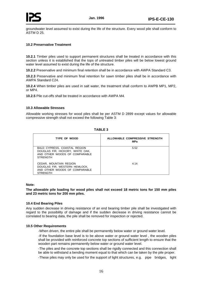
Allowable working stresses for wood piles shall be per ASTM D 2899 except values for allowable compressive strength shall not exceed the following Table 3:
TABLE 3
TYPE OF WOOD
ALLOWABLE COMPRESSIVE STRENGTH
MPa
BALD CYPRESS, COASTAL REGION DOUGLAS FIR, HICKORY, WHITE OAK, AND OTHER WOODS OF COMPARABLE STRENGTH CEDAR, MOUNTAIN REGION DOUGLAS FIR, WESTERN HEMLOCK, AND OTHER WOODS OF COMPARABLE STRENGTH
5.52
4.14
Note: The allowable pile loading for wood piles shall not exceed 18 metric tons for 150 mm piles and 23 metric tons for 200 mm piles. 10.4 End Bearing Piles Any sudden decrease in driving resistance of an end bearing timber pile shall be investigated with regard to the possibility of damage and if the sudden decrease in driving resistance cannot be correlated to bearing data, the pile shall be removed for inspection or rejected. 10.5 Other Requirements
-When driven, the entire pile shall be permanently below water or ground water level. -If the foundation base level is to be above water or ground water level , the wooden piles shall be provided with reinforced concrete top sections of sufficient length to ensure that the wooden part remains permanently below water or ground water level. -The piles and the concrete top sections shall be rigidly connected and this connection shall be able to withstand a bending moment equal to that which can be taken by the pile proper. -These piles may only be used for the support of light structures, e.g. pipe bridges, light
Jan. 1996
IPS-E-CE-130
17
vessels, pump foundations, etc. 11. COMPOSITE PILES 11.1 Design Composite piles are used in ground conditions where conventional piles are unsuitable or uneconomical. They may consist of a combination of bored and driven piles, or driven piles embodying two types of material. A frequently used type of composite pile is the concrete and timber pile. This type combines the cheapness and ease of handling of the timber pile with the durability of the concrete pile. The susceptibility of the former to decay above the ground water table has already been mentioned. Thus the timber pile is terminated below lowest ground water level and the upper portion formed in concrete. Another method of composite piling is to use a hollow precast concrete driven section which remains in position after a timber pile has been driven down the interior to the required penetration. Composite steel H-section and concrete piles can be driven in a similar manner to concrete and timber piles. The concrete portion is used in the zone above and immediately below ground level which is most susceptible to corrosion. The design of such composite piles should provide a rigid connection between the two components. 11.2 Limitation of Load The maximum allowable load shall be limited by the capacity of the weakest section incorporated in the pile. 11.3 Splices Splices between concrete section and steel or wood sections shall be designed to prevent separation of the sections both before and after the concrete portion has been set, and to insure the alignment and transmission of the total pile load. Splices shall be designed to resist uplift due to upheaval during driving of adjacent piles and shall develop the full compressive strength and not less than 50% of the strength in tension and bending of the weaker section. 12. CAISSON PILES 12.1 Definition Caissons are deep foundation units which often function similar to piles. However, these are essentially end-bearing units and designed as deep footings combined with concrete shafts to carry the structure loads to the bearing stratum. Caisson piles shall consist of a shaft section of concrete filled pipe extending to bedrock with an uncased socket drilled into the bedrock and filled with concrete. The caisson pile shall have a full length structural steel core or a stub core installed in the rock socket and extending into the pipe portion a distance equal to the socket depth. 12.2 Design The depth of the rock socket shall be sufficient to develop the full load bearing capacity of the caisson pile with a minimum factor of safety of two but the depth shall be not less than the outside diameter of the pipe. The design of the rock socket may be predicated on the sum of the allowable bearing pressure on the bottom of the socket plus bond along the sides of the socket. The minimum outside diameter of the caisson pile shall be 460 mm and the diameter of the rock socket shall be approximately equal to the inside diameter of the pipe. 12.3 Material Pipe and steel cores shall conform to the material requirements of Sub-clause 7.2.2. Pipe shall have a minimum wall thickness of 9.5 mm and shall be fitted with a suitable steel driving shoe welded to the bottom of the pipe. All concrete shall have a 28 day specified compressive
Jan. 1996
IPS-E-CE-130
18
strength f’c of not less than 28 MPa. The concrete mix shall be designed and proportioned so as to produce a cohesive workable mix with a slump of from 100 to 150 mm. 12.4 Structural Core The gross plan area of the structural steel core shall not exceed 25% of the gross caisson section. The minimum clearance between the structural core and the pipe shall be 50 mm. If cores are to be spliced, the ends shall be milled or ground to provide full contact and shall be full depth welded. 12.5 Allowable Stresses The allowable design compressive stresses shall not exceed the following:
Concrete, 0.33 f’c ; steel pipe, 0.35 f y; structural steel core, 0.50 fy.
Jan. 1996
IPS-E-CE-130
19
APPENDICES
APPENDIX A
CHOICE OF PILES
CHOICE OF TYPE
See section 7.3.2 BS 8004-1986.
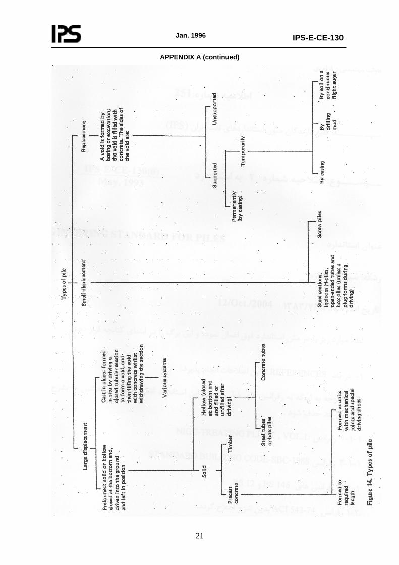
Piles may be divided into three main types, depending on their effect on the soil as shown in Fig. A-1. These are as follows:
a) Large displacement piles. These include all types of solid pile, including timber and precast concrete and steel or concrete tubes closed at the lower end by a shoe or plug, which may either be left in place or extruded to form an enlarged foot.
b) Small displacement piles. These include rolled steel sections, such as H piles, open-ended tubes and hollow sections if the ground enters freely during driving.
However, it should be recognized that open-ended tubes and hollow sections frequently plug and become displacement piles particularly in cohesive soils. H-piles may behave similarly.
c) Replacement piles. These are formed by boring or other methods of excavation; the borehole may be lined with a casing or tube that is either left in place or extracted as the hole is filled.
When considering a bored pile in soft or granular ground especially when water-bearing, particular care will need to be taken to ensure the integrity of the pile shaft and to avoid:
1) disturbance causing instability of the bearing stratum and the surrounding ground;
2) an inflow of water which could cause a disturbance to the bearing stratum or the surrounding ground;
3) an inflow of water or soil causing damage to the unset concrete in the pile or piles recently installed nearby.
When a displacement pile is installed, its volume has to be accommodated below the ground surface by vertical and lateral displacements of the soil. Effects of consequential heave or compaction may be unacceptable to adjacent structures.
In some soils the vertical and lateral displacement or heave resulting from subsequent piling may carry with it piles that have already been installed. This may cause end bearing piles to be lifted off their bearing stratum. If lifting is suspected, careful levelling from a datum unaffected by the piling should be made on the heads of piles already driven before and after driving subsequent piles. Risen piles which depend largely on end bearing and which are capable of being redriven should be redriven to the specified resistance.
Driven cast in situ piles should not normally be redriven after concreting and should be replaced or supplemented or the required resistance developed by pre-loading the piles.
1The soil around a driven pile is disturbed during installation and with a pile group the volume of soil affected may be considerable. Mitigation of this effect can be obtained by the use of small displacement piles, or by pre-boring over part of the depth of displacement piles or, if the ground conditions are suitable, by the use of bored piles. Where large displacement piles are to be employed in ground liable to heave, the effects on adjacent piles and structures can usually be minimized by working outward from the center of a group or by commencing with the piles adjacent to the structure and progressing away from it.
Where vibration or noise has to be reduced to a minimum, piles formed by augering are generally preferable. However, piles driven under carefully controlled conditions do not necessarily cause appreciable vibration and may then be used safely under skilled supervision. When working near existing structures which are founded on loose sands or silts, particularly if these are saturated, it is essential to avoid the use of methods which cause dangerous vibrations, because these may have
Jan. 1996
IPS-E-CE-130
20
the effect of temporarily reducing the shear strength of the ground beneath the adjoining foundations.
Rapid settlement may also occur due to consolidation of loose sands and silts. If bored piles are used in loose sands and silts, care should be taken to prevent inflow of soil into the boreholes, as this might cause loss of support by the removal of soil from beneath adjacent foundations or create unstable water-filled cavities outside the pile shaft, leading to voids in the shaft during concreting or the washing out of cement.
Where headroom is limited, a pile installed in sections by jacking it into the ground may be used, for example where underpinning is to be carried out, but care is required to ensure that the reaction available is adequate. Some rigs for installing bored piles and some proprietary rigs for driven piles are also capable of working in confined headroom.
Whilst they are rarely used, screw piles are suitable for the construction of structures such as wharves, piers and jetties where there is soft alluvial soil to a considerable depth.
They may also be used to withstand uplift forces.
Timber piles may be used in permanent work where the conditions are such that deterioration will not occur.
(to be continued)
Jan. 1996
IPS-E-CE-130
21
APPENDIX A (continued)
Jan. 1996
IPS-E-CE-130
22
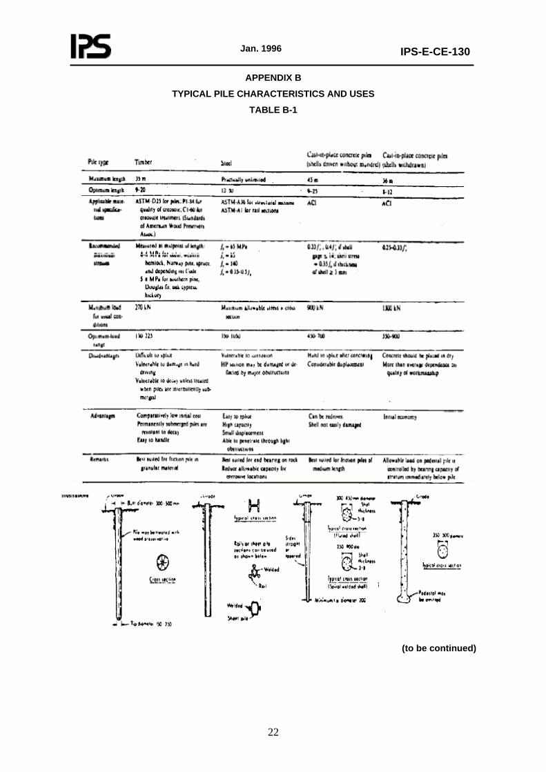
APPENDIX B
TYPICAL PILE CHARACTERISTICS AND USES
TABLE B-1
(to be continued)
Jan. 1996
IPS-E-CE-130
23
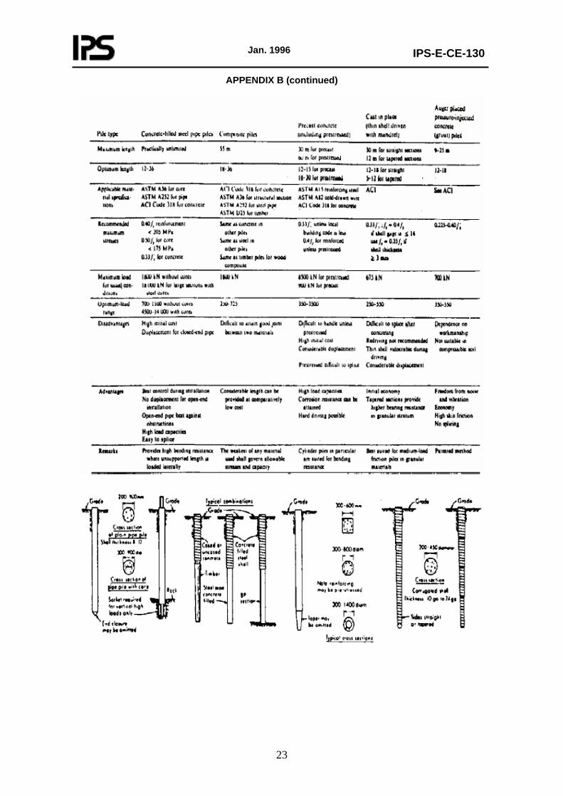
APPENDIX B (continued)