Embed Size (px)
Citation preview

ENSTROM F-28F/280F SERIES MAINTENANCE MANUAL
Revision 10, dated Feb 7/19, applies to the Enstrom F-28F/280F Series Maintenance Manual, 1985 Edition/1990 2nd Edition. Place this cover sheet behind the “Record of Revisions” card after removing and inserting the pages listed below.
Remove Pages Insert Pages
Cover (title page) Cover (title page)
ix through x ix through x
None xiii through xiv
MM-4-39 through MM-4-42 MM-4-39 through MM-4-42
MM-8-0 through MM-8-0.3 MM-8-0 through MM-8-0.3
MM-8-11 through MM-8-16 MM-8-11 through MM-8-16.2
MM-12-17 through MM-12-22 MM-12-17 through MM-12-22
MM-21-1 through MM-21-8 MM-21-1 through MM-21-8
MM-21-13 through MM-21-14 MM-21-13 through MM-21-14
None MM-21-33 through MM-21-58
None MM-24-7 through MM-24-8
............................................................. End of List .........................................................................

INTENTIONALLY LEFT BLANK
ENSTROM F-28F AND 280F SERIES MAINTENANCE MANUAL
Copyright 1985-2019 The Enstrom Helicopter Corporation
2209 22nd Street Menominee, Michigan 49858-3515
Telephone: 906-863-1200
Fax: 906-863-6821 www.enstromhelicopter.com

INTENTIONALLY LEFT BLANK
ENSTROM F-28F/280F SERIES MAINTENANCE MANUAL
Rev. 10 ix Feb 7/19
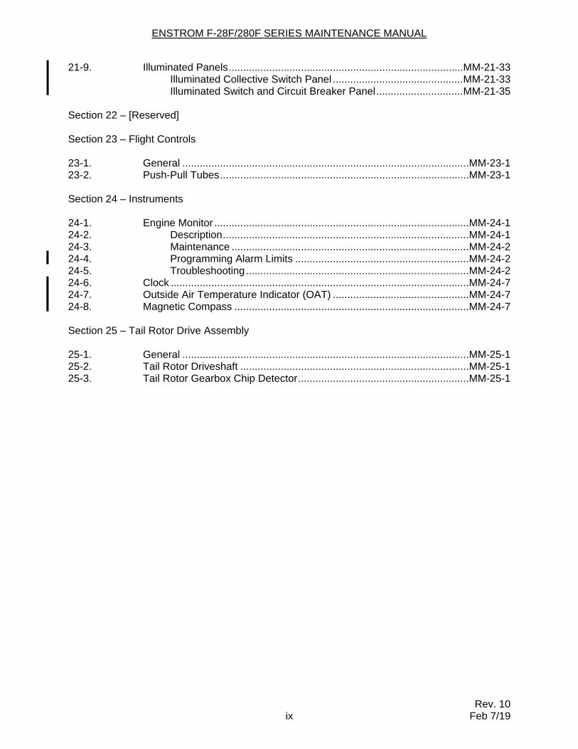
21-9. Illuminated Panels ................................................................................. MM-21-33 Illuminated Collective Switch Panel ............................................. MM-21-33 Illuminated Switch and Circuit Breaker Panel .............................. MM-21-35 Section 22 – [Reserved] Section 23 – Flight Controls 23-1. General ................................................................................................... MM-23-1 23-2. Push-Pull Tubes ...................................................................................... MM-23-1 Section 24 – Instruments 24-1. Engine Monitor ........................................................................................ MM-24-1 24-2. Description ..................................................................................... MM-24-1 24-3. Maintenance .................................................................................. MM-24-2 24-4. Programming Alarm Limits ............................................................ MM-24-2 24-5. Troubleshooting ............................................................................. MM-24-2 24-6. Clock ....................................................................................................... MM-24-7 24-7. Outside Air Temperature Indicator (OAT) ............................................... MM-24-7 24-8. Magnetic Compass ................................................................................. MM-24-7 Section 25 – Tail Rotor Drive Assembly 25-1. General ................................................................................................... MM-25-1 25-2. Tail Rotor Driveshaft ............................................................................... MM-25-1 25-3. Tail Rotor Gearbox Chip Detector ........................................................... MM-25-1

ENSTROM F-28F/280F SERIES MAINTENANCE MANUAL
Rev. 5 x Nov 5/13
INTENTIONALLY LEFT BLANK
ENSTROM F-28F/280F SERIES MAINTENANCE MANUAL
Rev. 10 xiii Feb 7/19
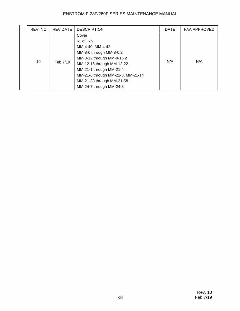
REV. NO REV DATE DESCRIPTION DATE FAA APPROVED
10 Feb 7/19
Cover
ix, xiii, xiv
MM-4-40, MM-4-42
MM-8-0 through MM-8-0.2
MM-8-12 through MM-8-16.2
MM-12-18 through MM-12-22
MM-21-1 through MM-21-4
MM-21-6 through MM-21-8, MM-21-14
MM-21-33 through MM-21-58
MM-24-7 through MM-24-8
N/A N/A

ENSTROM F-28F/280F SERIES MAINTENANCE MANUAL
Rev. 10 xiv Feb 7/19
INTENTIONALLY LEFT BLANK
ENSTROM F-28F/280F SERIES MAINTENANCE MANUAL
Rev. 4 MM-4-39 Jun 21/12
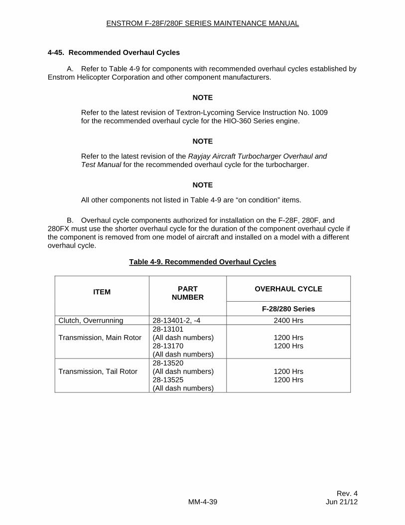
4-45. Recommended Overhaul Cycles
A. Refer to Table 4-9 for components with recommended overhaul cycles established by Enstrom Helicopter Corporation and other component manufacturers.
NOTE
Refer to the latest revision of Textron-Lycoming Service Instruction No. 1009 for the recommended overhaul cycle for the HIO-360 Series engine.
NOTE
Refer to the latest revision of the Rayjay Aircraft Turbocharger Overhaul and Test Manual for the recommended overhaul cycle for the turbocharger.
NOTE
All other components not listed in Table 4-9 are “on condition” items.
B. Overhaul cycle components authorized for installation on the F-28F, 280F, and 280FX must use the shorter overhaul cycle for the duration of the component overhaul cycle if the component is removed from one model of aircraft and installed on a model with a different overhaul cycle.
Table 4-9. Recommended Overhaul Cycles
ITEM
PART
NUMBER
OVERHAUL CYCLE
F-28/280 Series
Clutch, Overrunning 28-13401-2, -4 2400 Hrs
Transmission, Main Rotor
28-13101 (All dash numbers) 28-13170 (All dash numbers)
1200 Hrs 1200 Hrs
Transmission, Tail Rotor
28-13520 (All dash numbers) 28-13525 (All dash numbers)
1200 Hrs 1200 Hrs
ENSTROM F-28F/280F SERIES MAINTENANCE MANUAL
Rev. 10 MM-4-40 Feb 7/19
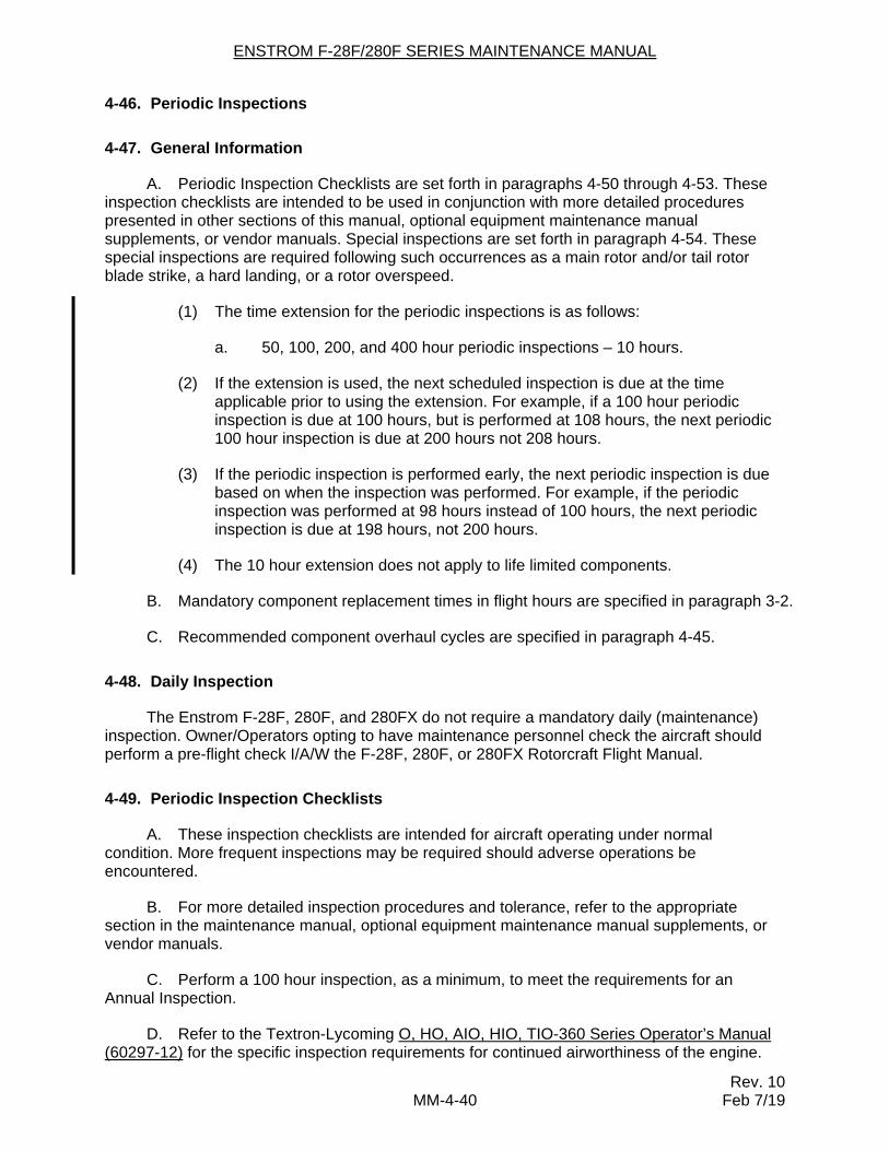
4-46. Periodic Inspections
4-47. General Information
A. Periodic Inspection Checklists are set forth in paragraphs 4-50 through 4-53. These inspection checklists are intended to be used in conjunction with more detailed procedures presented in other sections of this manual, optional equipment maintenance manual supplements, or vendor manuals. Special inspections are set forth in paragraph 4-54. These special inspections are required following such occurrences as a main rotor and/or tail rotor blade strike, a hard landing, or a rotor overspeed.
(1) The time extension for the periodic inspections is as follows:
a. 50, 100, 200, and 400 hour periodic inspections – 10 hours.
(2) If the extension is used, the next scheduled inspection is due at the time applicable prior to using the extension. For example, if a 100 hour periodic inspection is due at 100 hours, but is performed at 108 hours, the next periodic 100 hour inspection is due at 200 hours not 208 hours.
(3) If the periodic inspection is performed early, the next periodic inspection is due based on when the inspection was performed. For example, if the periodic inspection was performed at 98 hours instead of 100 hours, the next periodic inspection is due at 198 hours, not 200 hours.
(4) The 10 hour extension does not apply to life limited components.
B. Mandatory component replacement times in flight hours are specified in paragraph 3-2.
C. Recommended component overhaul cycles are specified in paragraph 4-45.
4-48. Daily Inspection
The Enstrom F-28F, 280F, and 280FX do not require a mandatory daily (maintenance) inspection. Owner/Operators opting to have maintenance personnel check the aircraft should perform a pre-flight check I/A/W the F-28F, 280F, or 280FX Rotorcraft Flight Manual.
4-49. Periodic Inspection Checklists
A. These inspection checklists are intended for aircraft operating under normal condition. More frequent inspections may be required should adverse operations be encountered.
B. For more detailed inspection procedures and tolerance, refer to the appropriate section in the maintenance manual, optional equipment maintenance manual supplements, or vendor manuals.
C. Perform a 100 hour inspection, as a minimum, to meet the requirements for an Annual Inspection.
D. Refer to the Textron-Lycoming O, HO, AIO, HIO, TIO-360 Series Operator’s Manual (60297-12) for the specific inspection requirements for continued airworthiness of the engine.
ENSTROM F-28F/280F SERIES MAINTENANCE MANUAL
Rev. 8 MM-4-41 Sep 20/17
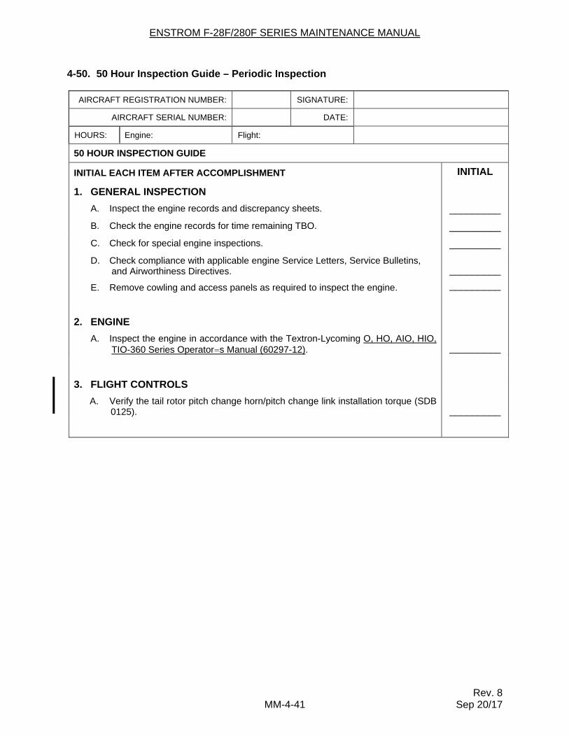
4-50. 50 Hour Inspection Guide – Periodic Inspection
AIRCRAFT REGISTRATION NUMBER: SIGNATURE:
AIRCRAFT SERIAL NUMBER: DATE:
HOURS: Engine: Flight:
50 HOUR INSPECTION GUIDE
INITIAL EACH ITEM AFTER ACCOMPLISHMENT INITIAL
1. GENERAL INSPECTION
A. Inspect the engine records and discrepancy sheets. _________
B. Check the engine records for time remaining TBO. _________
C. Check for special engine inspections. _________
D. Check compliance with applicable engine Service Letters, Service Bulletins, and Airworthiness Directives.
_________
E. Remove cowling and access panels as required to inspect the engine. _________
2. ENGINE
A. Inspect the engine in accordance with the Textron-Lycoming O, HO, AIO, HIO, TIO-360 Series Operator=s Manual (60297-12).
_________
3. FLIGHT CONTROLS
A. Verify the tail rotor pitch change horn/pitch change link installation torque (SDB 0125).
_________
ENSTROM F-28F/280F SERIES MAINTENANCE MANUAL
Rev. 10 MM-4-42 Feb 7/19
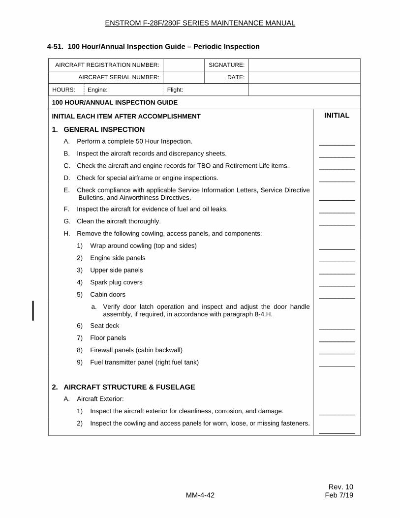
4-51. 100 Hour/Annual Inspection Guide – Periodic Inspection
AIRCRAFT REGISTRATION NUMBER: SIGNATURE:
AIRCRAFT SERIAL NUMBER: DATE:
HOURS: Engine: Flight:
100 HOUR/ANNUAL INSPECTION GUIDE
INITIAL EACH ITEM AFTER ACCOMPLISHMENT INITIAL
1. GENERAL INSPECTION
A. Perform a complete 50 Hour Inspection. _________
B. Inspect the aircraft records and discrepancy sheets. _________
C. Check the aircraft and engine records for TBO and Retirement Life items. _________
D. Check for special airframe or engine inspections. _________
E. Check compliance with applicable Service Information Letters, Service Directive Bulletins, and Airworthiness Directives.
_________
F. Inspect the aircraft for evidence of fuel and oil leaks. _________
G. Clean the aircraft thoroughly. _________
H. Remove the following cowling, access panels, and components:
1) Wrap around cowling (top and sides) _________
2) Engine side panels _________
3) Upper side panels _________
4) Spark plug covers _________
5) Cabin doors _________
a. Verify door latch operation and inspect and adjust the door handle assembly, if required, in accordance with paragraph 8-4.H.
6) Seat deck _________
7) Floor panels _________
8) Firewall panels (cabin backwall) _________
9) Fuel transmitter panel (right fuel tank) _________
2. AIRCRAFT STRUCTURE & FUSELAGE
A. Aircraft Exterior:
1) Inspect the aircraft exterior for cleanliness, corrosion, and damage. _________
2) Inspect the cowling and access panels for worn, loose, or missing fasteners. _________
ENSTROM F-28F/280F SERIES MAINTENANCE MANUAL
Rev. 10 MM-8-0 Feb 7/19
SECTION 8
STRUCTURE
TABLE OF CONTENTS
Paragraph Description Page
Table of Contents ...................................................................................... MM-8-0 8-1 Cabin ........................................................................................................ MM-8-1 Removal ............................................................................................. MM-8-1 Inspection ........................................................................................... MM-8-2 Repair ................................................................................................. MM-8-2 Installation .......................................................................................... MM-8-2 8-2 Windshields and Windows ..................................................................... MM-8-4 Inspection ........................................................................................... MM-8-4 Repair ................................................................................................. MM-8-4 F-28F Windshield Removal ............................................................................................. MM-8-4 Installation .......................................................................................... MM-8-6 280F Series Windshield Removal ............................................................................................. MM-8-8 Installation .......................................................................................... MM-8-8 Overhead and Lower Windows (All F-28F and 280F/FX) Removal ........................................................................................... MM-8-10 Installation ........................................................................................ MM-8-11 8-4 Cabin Doors ........................................................................................... MM-8-11 F-28F Cabin Door Removal – Door ................................................................................ MM-8-11 Inspection – Door ............................................................................ MM-8-12 Repair – Door ................................................................................... MM-8-13 Installation – Door ............................................................................. MM-8-13 Removal – Glass .............................................................................. MM-8-13 Installation – Glass ........................................................................... MM-8-14 280F Series Cabin Door Removal – Door ................................................................................ MM-8-14 Disassembly – Door ...................................................................... MM-8-16.1 Assembly – Door ........................................................................... MM-8-16.1 Inspection – Door .......................................................................... MM-8-16.2 Repair – Door ................................................................................ MM-8-16.2 Installation – Door .......................................................................... MM-8-16.2 Installation – Glass ........................................................................ MM-8-16.2 8-5 [Reserved – Original content incorporated into Paragraph 8-4] 8-6 [Reserved – Original content incorporated into Paragraph 8-2] 8-7 Seat Belts, Lap Type ............................................................................. MM-8-17 Removal ........................................................................................... MM-8-17 Installation ........................................................................................ MM-8-17 8-8 Seat Deck ............................................................................................... MM-8-18 Removal ........................................................................................... MM-8-19 Inspection ......................................................................................... MM-8-19 Repair ............................................................................................... MM-8-19 Installation ........................................................................................ MM-8-19
ENSTROM F-28F/280F SERIES MAINTENANCE MANUAL
Rev. 10 MM-8-0.1 Feb 7/19
SECTION 8
STRUCTURE
TABLE OF CONTENTS
Paragraph Description Page
8-9 Landing Gear ......................................................................................... MM-8-19 Landing Gear Assembly Removal ........................................................................................... MM-8-19 Inspection ......................................................................................... MM-8-21 Skid Shoes Inspection ......................................................................................... MM-8-23 Replacement .................................................................................... MM-8-23 Ground Handling Wheels Operational Description .................................................................... MM-8-23 Removal ........................................................................................... MM-8-23 Installation ........................................................................................ MM-8-24 Oleo Struts Removal ........................................................................................... MM-8-27 Disassembly ..................................................................................... MM-8-27 Inspection ......................................................................................... MM-8-28 Assembly .......................................................................................... MM-8-28 Installation ........................................................................................ MM-8-36 Landing Gear Fairings (280FX) Removal – Access to Service the Oleo Strut .................................... MM-8-37 Removal – Access for Oleo Strut Removal ...................................... MM-8-37 Inspection ......................................................................................... MM-8-37 Assembly – After Oleo Replacement ................................................ MM-8-37 8-10 Pylon ...................................................................................................... MM-8-39 Removal and Installation .................................................................. MM-8-39 Inspection ......................................................................................... MM-8-39 Repair ............................................................................................... MM-8-39 8-11 Baggage Compartment ......................................................................... MM-8-39 Removal ........................................................................................... MM-8-39 Inspection ......................................................................................... MM-8-41 Repair ............................................................................................... MM-8-41 Installation ........................................................................................ MM-8-41 8-12 Tailcone Assembly ................................................................................ MM-8-42 Removal ........................................................................................... MM-8-42 Inspection ......................................................................................... MM-8-42 Repair ............................................................................................... MM-8-42 Installation ........................................................................................ MM-8-42 8-12.1 Tubular Tail Rotor Guard (F-28F Post-1986; 280FX) .......................... MM-8-44 Removal ........................................................................................... MM-8-44 Inspection ......................................................................................... MM-8-44 Installation ........................................................................................ MM-8-45 8-12.2 Tail Rotor Driveshaft Cover (280FX) .................................................... MM-8-45 Cover Opening – Tail Rotor Driveshaft Access ................................ MM-8-45 Inspection ......................................................................................... MM-8-45 Cover Closing ................................................................................... MM-8-45
ENSTROM F-28F/280F SERIES MAINTENANCE MANUAL
Rev. 10 MM-8-0.2 Feb 7/19
SECTION 8
STRUCTURE
TABLE OF CONTENTS
Paragraph Description Page
8-13 Torque Tube Extension ........................................................................ MM-8-46 Removal ........................................................................................... MM-8-46 Inspection ......................................................................................... MM-8-46 Repair ............................................................................................... MM-8-46 Installation ........................................................................................ MM-8-48 8-14 Horizontal Stabilizers (F-28F Pre-1986) ............................................... MM-8-48 Removal ........................................................................................... MM-8-48 Inspection ......................................................................................... MM-8-48 Installation ........................................................................................ MM-8-49 8-15 Horizontal Stabilizers (280F) ................................................................ MM-8-49 Removal ........................................................................................... MM-8-49 Inspection ......................................................................................... MM-8-50 Installation ........................................................................................ MM-8-50 8-16 Horizontal and Vertical Stabilizers (F-28F Post-1986; 280FX) .......... MM-8-50 Removal ........................................................................................... MM-8-50 Inspection ......................................................................................... MM-8-51 Installation ........................................................................................ MM-8-51 Assembly – Endplate ........................................................................ MM-8-51 8-17 Airscoop (280FX) ................................................................................... MM-8-59 Removal – Access (Upper Drive System/Main Rotor Gearbox Removal) .......................................................................................... MM-8-59 Installation ........................................................................................ MM-8-59

ENSTROM F-28F/280F SERIES MAINTENANCE MANUAL
Rev. 8 MM-8-0.3 Sep 20/17
INTENTIONALLY LEFT BLANK
ENSTROM F-28F/280F SERIES MAINTENANCE MANUAL
Rev. 8 MM-8-11 Sep 20/17
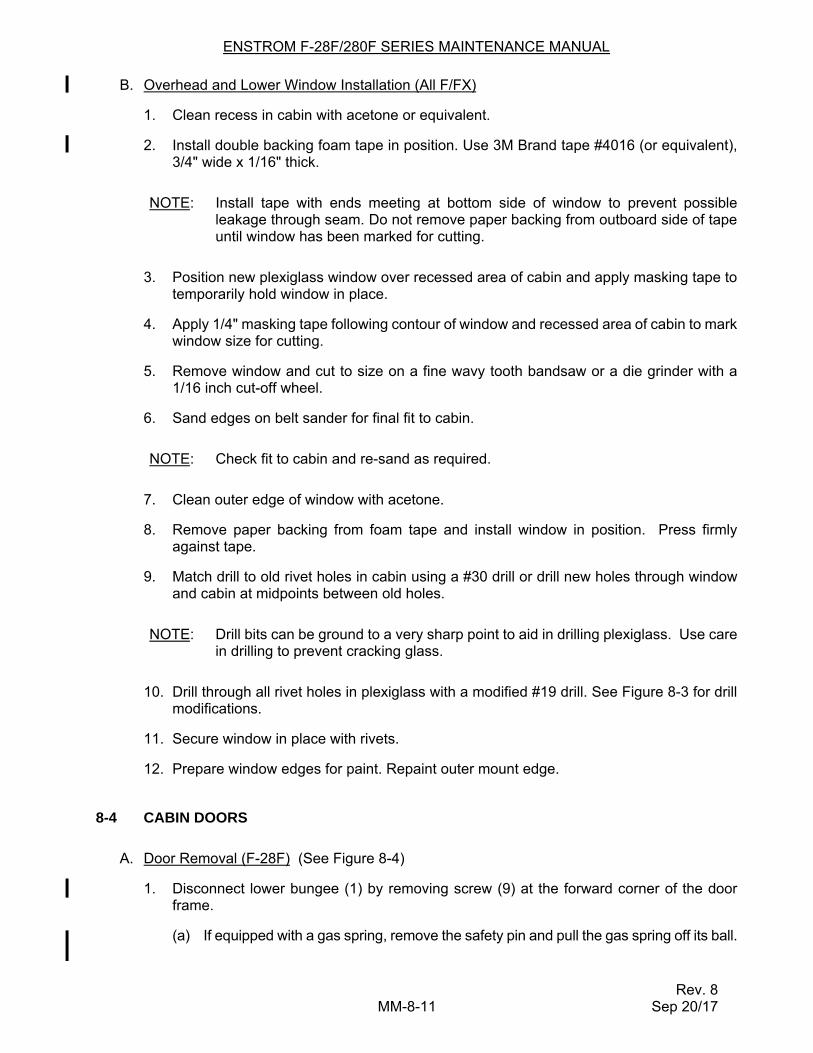
B. Overhead and Lower Window Installation (All F/FX)
1. Clean recess in cabin with acetone or equivalent.
2. Install double backing foam tape in position. Use 3M Brand tape #4016 (or equivalent), 3/4" wide x 1/16" thick.
NOTE: Install tape with ends meeting at bottom side of window to prevent possible leakage through seam. Do not remove paper backing from outboard side of tape until window has been marked for cutting.
3. Position new plexiglass window over recessed area of cabin and apply masking tape to temporarily hold window in place.
4. Apply 1/4" masking tape following contour of window and recessed area of cabin to mark window size for cutting.
5. Remove window and cut to size on a fine wavy tooth bandsaw or a die grinder with a 1/16 inch cut-off wheel.
6. Sand edges on belt sander for final fit to cabin.
NOTE: Check fit to cabin and re-sand as required.
7. Clean outer edge of window with acetone.
8. Remove paper backing from foam tape and install window in position. Press firmly against tape.
9. Match drill to old rivet holes in cabin using a #30 drill or drill new holes through window and cabin at midpoints between old holes.
NOTE: Drill bits can be ground to a very sharp point to aid in drilling plexiglass. Use care in drilling to prevent cracking glass.
10. Drill through all rivet holes in plexiglass with a modified #19 drill. See Figure 8-3 for drill modifications.
11. Secure window in place with rivets.
12. Prepare window edges for paint. Repaint outer mount edge.
8-4 CABIN DOORS
A. Door Removal (F-28F) (See Figure 8-4)
1. Disconnect lower bungee (1) by removing screw (9) at the forward corner of the door frame.
(a) If equipped with a gas spring, remove the safety pin and pull the gas spring off its ball.
ENSTROM F-28F/280F SERIES MAINTENANCE MANUAL
Rev. 10 MM-8-12 Feb 7/19
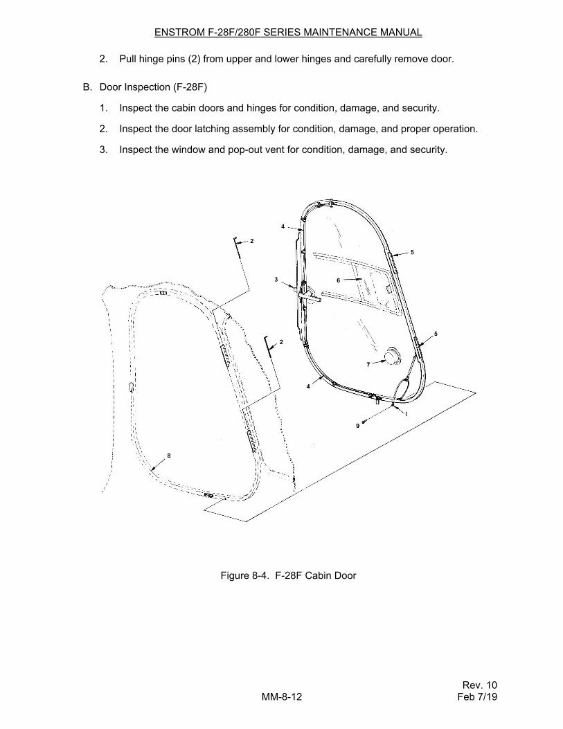
2. Pull hinge pins (2) from upper and lower hinges and carefully remove door.
B. Door Inspection (F-28F)
1. Inspect the cabin doors and hinges for condition, damage, and security.
2. Inspect the door latching assembly for condition, damage, and proper operation.
3. Inspect the window and pop-out vent for condition, damage, and security.
Figure 8-4. F-28F Cabin Door
ENSTROM F-28F/280F SERIES MAINTENANCE MANUAL
Rev. 10 MM-8-13 Feb 7/19
C. Door Repair (F-28F)
1. Repair the door I/A/W AC 43.13-1B. Contact The Enstrom Helicopter Corporation Customer Service for detailed damage and repair limitations.
2. Replace the seal strips around the door if deteriorated or damaged. Attach the new seal using trim adhesive 8031 (3M) or equivalent.
3. Replace components of the door latching assembly that are unserviceable.
D. Door Installation (F-28F) (See Figure 8-4)
1. Align door to hinges and install hinge pins (2).
2. Attach lower bungee (1) or gas spring, if equipped, with screw (9) at the forward corner of the door frame.
3. Check operation of the door latch and upper and lower retaining lugs.
E. Door Glass Removal (F-28F) (See Figure 8-4)
NOTE: For installation of door glass on later F-28F model doors (S/N 744 and subsequent), refer to the Enstrom Helicopter Corporation website, 280FX Technical Tips for replacing the door glass. Otherwise, the door should be returned to Enstrom Helicopter Service for glass replacement.
1. Disconnect cables and remove door handle (3).
NOTE: Remove the roll pin from the inboard door handle and separate and remove external door handle.
2. Remove cables (4) and lower bungee (1) from door frame.
3. Mark door hinges (5) as to their position on door frame and remove hinges.
NOTE: Hinges cannot be alternated for upper and lower positions.
4. Remove sliding vent window (6) and snap vents (7).
5. Remove foam strip from outer edge of door frame.
6. Remove screws securing T-molding (8) and remove molding.
7. Remove screws from door glass. Heat bonded area of plexiglass with a portable heat gun and remove glass from door frame.
NOTE: Use care in glass removal to prevent distortion of tubular door frame.
8. Remove excess bonding adhesive from door frame with a putty knife. Sand frame clean.
ENSTROM F-28F/280F SERIES MAINTENANCE MANUAL
Rev. 10 MM-8-14 Feb 7/19
NOTE: When ordering a replacement door glass, be sure to specify if a sliding vent window and/or snap vents are required so they can be installed at the factory.
F. Door Glass Installation (F-28F) (See Figure 8-4)
NOTE: Check fit of door frame to cabin before locating glass on frame.
1. Position new glass on door frame and match drill to screw holes using a #41 drill. Countersink holes using an 82 countersink.
NOTE: Replacement door glass has been rough cut to size. Final sanding of plexiglass to door frame is completed after bonding procedure is done.
2. Remove door glass from frame and clean bonding surfaces of both items using acetone or equivalent.
3. Apply bonding adhesive PR-1425 B-2 (or equivalent) to bonding surface of door frame. Spread adhesive approximately 1/8" to 3/16" thick.
4. Carefully install door glass on door frame.
NOTE: Install enough screws in door glass and frame to hold glass in position. DO NOT tighten screws until bonding adhesive is set up (approximately 24 hours).
5. Install screws to secure door glass to frame.
6. Final fit plexiglass to door frame by sanding on belt sander.
7. Install T-molding (8) to door frame and secure with screws.
8. Install foam strip on outer edge of door frame.
9. Install and secure hinges (5) to their previously marked position on door frame.
10. Prepare and repaint door frame.
11. Install and secure door handles (3), cables (4), and latches.
12. Install lower bungee (1) or gas spring at forward corner of door frame, as applicable.
13. Install door on aircraft and check operation of door handle and latch.
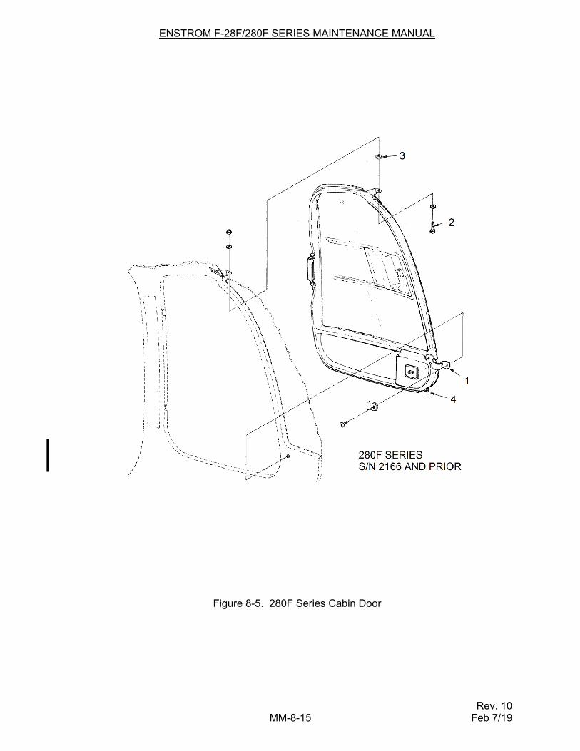
G. Door Removal (280F Series) (S/N 2166 and Prior) (See Figure 8-5)
1. Remove screw from door strap (1) on the lower corner of the door.
(a) If equipped with a gas spring, remove the safety pin and pull the gas spring off its ball.
2. Remove bolt (2) and spacer (3) from hinge pivot point at top of door.
3. Carefully lift door from cabin frame.
ENSTROM F-28F/280F SERIES MAINTENANCE MANUAL
Rev. 10 MM-8-15 Feb 7/19
Figure 8-5. 280F Series Cabin Door
ENSTROM F-28F/280F SERIES MAINTENANCE MANUAL
Rev. 10 MM-8-16 Feb 7/19
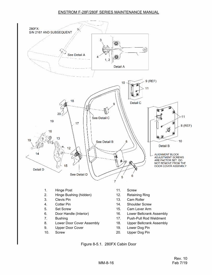
1. Hinge Post 11. Screw 2. Hinge Bushing (hidden) 12. Retaining Ring 3. Clevis Pin 13. Cam Roller 4. Cotter Pin 14. Shoulder Screw 5. Set Screw 15. Cam Lever Arm 6. Door Handle (Interior) 16. Lower Bellcrank Assembly 7. Bushing 17. Push-Pull Rod Weldment 8. Lower Door Cover Assembly 18. Upper Bellcrank Assembly 9. Upper Door Cover 19. Lower Dog Pin 10. Screw 20. Upper Dog Pin
Figure 8-5.1. 280FX Cabin Door
ENSTROM F-28F/280F SERIES MAINTENANCE MANUAL
Rev. 10 MM-8-16.1 Feb 7/19
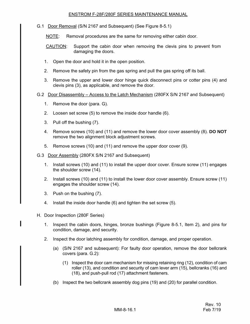
G.1 Door Removal (S/N 2167 and Subsequent) (See Figure 8-5.1)
NOTE: Removal procedures are the same for removing either cabin door.
CAUTION: Support the cabin door when removing the clevis pins to prevent from damaging the doors.
1. Open the door and hold it in the open position.
2. Remove the safety pin from the gas spring and pull the gas spring off its ball.
3. Remove the upper and lower door hinge quick disconnect pins or cotter pins (4) and clevis pins (3), as applicable, and remove the door.
G.2 Door Disassembly – Access to the Latch Mechanism (280FX S/N 2167 and Subsequent)
1. Remove the door (para. G).
2. Loosen set screw (5) to remove the inside door handle (6).
3. Pull off the bushing (7).
4. Remove screws (10) and (11) and remove the lower door cover assembly (8). DO NOT remove the two alignment block adjustment screws.
5. Remove screws (10) and (11) and remove the upper door cover (9).
G.3 Door Assembly (280FX S/N 2167 and Subsequent)
1. Install screws (10) and (11) to install the upper door cover. Ensure screw (11) engages the shoulder screw (14).
2. Install screws (10) and (11) to install the lower door cover assembly. Ensure screw (11) engages the shoulder screw (14).
3. Push on the bushing (7).
4. Install the inside door handle (6) and tighten the set screw (5).
H. Door Inspection (280F Series)
1. Inspect the cabin doors, hinges, bronze bushings (Figure 8-5.1, Item 2), and pins for condition, damage, and security.
2. Inspect the door latching assembly for condition, damage, and proper operation.
(a) (S/N 2167 and subsequent): For faulty door operation, remove the door bellcrank covers (para. G.2):
(1) Inspect the door cam mechanism for missing retaining ring (12), condition of cam roller (13), and condition and security of cam lever arm (15), bellcranks (16) and (18), and push-pull rod (17) attachment fasteners.
(b) Inspect the two bellcrank assembly dog pins (19) and (20) for parallel condition.
ENSTROM F-28F/280F SERIES MAINTENANCE MANUAL
Rev. 10 MM-8-16.2 Feb 7/19
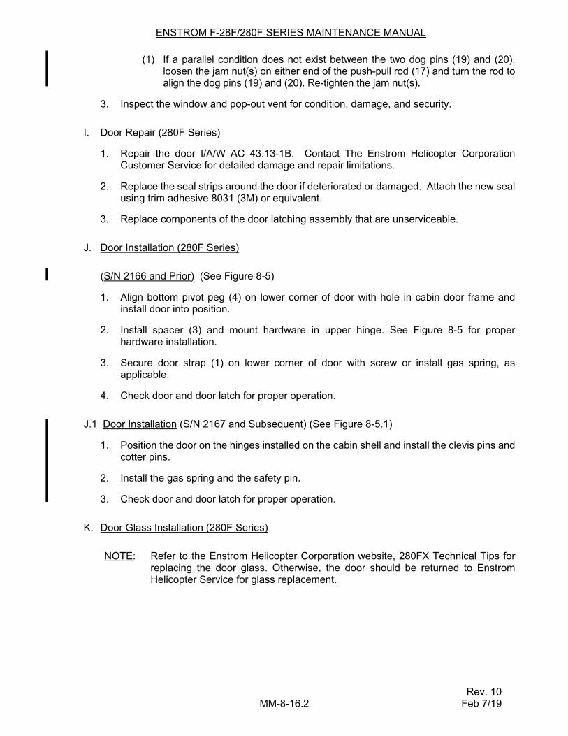
(1) If a parallel condition does not exist between the two dog pins (19) and (20), loosen the jam nut(s) on either end of the push-pull rod (17) and turn the rod to align the dog pins (19) and (20). Re-tighten the jam nut(s).
3. Inspect the window and pop-out vent for condition, damage, and security.
I. Door Repair (280F Series)
1. Repair the door I/A/W AC 43.13-1B. Contact The Enstrom Helicopter Corporation Customer Service for detailed damage and repair limitations.
2. Replace the seal strips around the door if deteriorated or damaged. Attach the new seal using trim adhesive 8031 (3M) or equivalent.
3. Replace components of the door latching assembly that are unserviceable.
J. Door Installation (280F Series)
(S/N 2166 and Prior) (See Figure 8-5)
1. Align bottom pivot peg (4) on lower corner of door with hole in cabin door frame and install door into position.
2. Install spacer (3) and mount hardware in upper hinge. See Figure 8-5 for proper hardware installation.
3. Secure door strap (1) on lower corner of door with screw or install gas spring, as applicable.
4. Check door and door latch for proper operation.
J.1 Door Installation (S/N 2167 and Subsequent) (See Figure 8-5.1)
1. Position the door on the hinges installed on the cabin shell and install the clevis pins and cotter pins.
2. Install the gas spring and the safety pin.
3. Check door and door latch for proper operation.
K. Door Glass Installation (280F Series)
NOTE: Refer to the Enstrom Helicopter Corporation website, 280FX Technical Tips for replacing the door glass. Otherwise, the door should be returned to Enstrom Helicopter Service for glass replacement.
ENSTROM F-28F/280F SERIES MAINTENANCE MANUAL
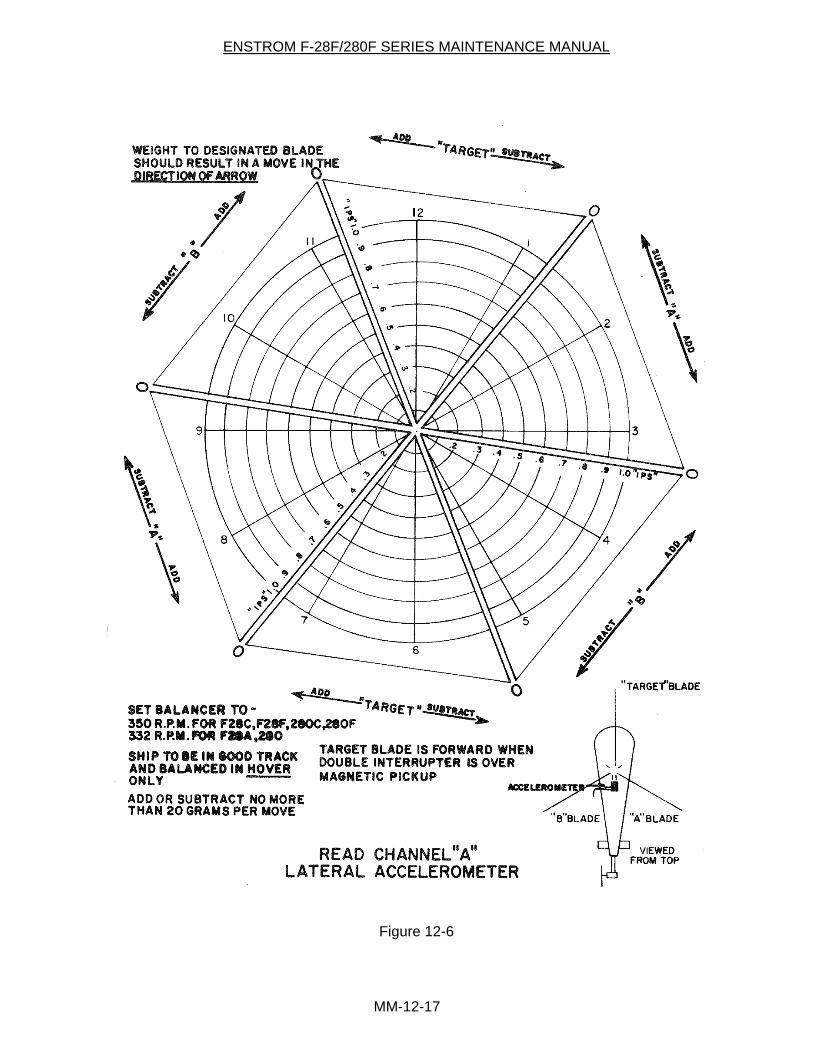
MM-12-17
Figure 12-6
ENSTROM F-28F/280F SERIES MAINTENANCE MANUAL
Rev. 10 MM-12-18 Feb 7/19
(5) Add or subtract "tip weights" until IPS is below .2 IPS and aircraft is smooth.
NOTE: The addition or subtraction of tip weights will sometimes affect the "vertical." If so, revert back to Item J for corrections.
L. Forward Flight Tracking
(1) Level flight in cruise, rpm stable (3050 RPM)
(2) Observe track with Strobex and record conditions.
(3) Switch balancer to channel "B" and record "clock angle" and "IPS."
(4) Plot move on vertical chart "B."
(5) Adjust condition using inboard tab.
NOTE: (a) Use no more than 2 per move.
(b) Do not bend inboard tab in opposite direction of an outboard tab on the same blade. If this move is required, subtract a degree of tab from the outboard.
(c) Observe cyclic feedback.
(d) Any time a move is made on an outboard tab it will require a pitch link adjustment to make hover smooth.
12-4 COLLECTIVE PITCH CONTROL STICK
1. Description
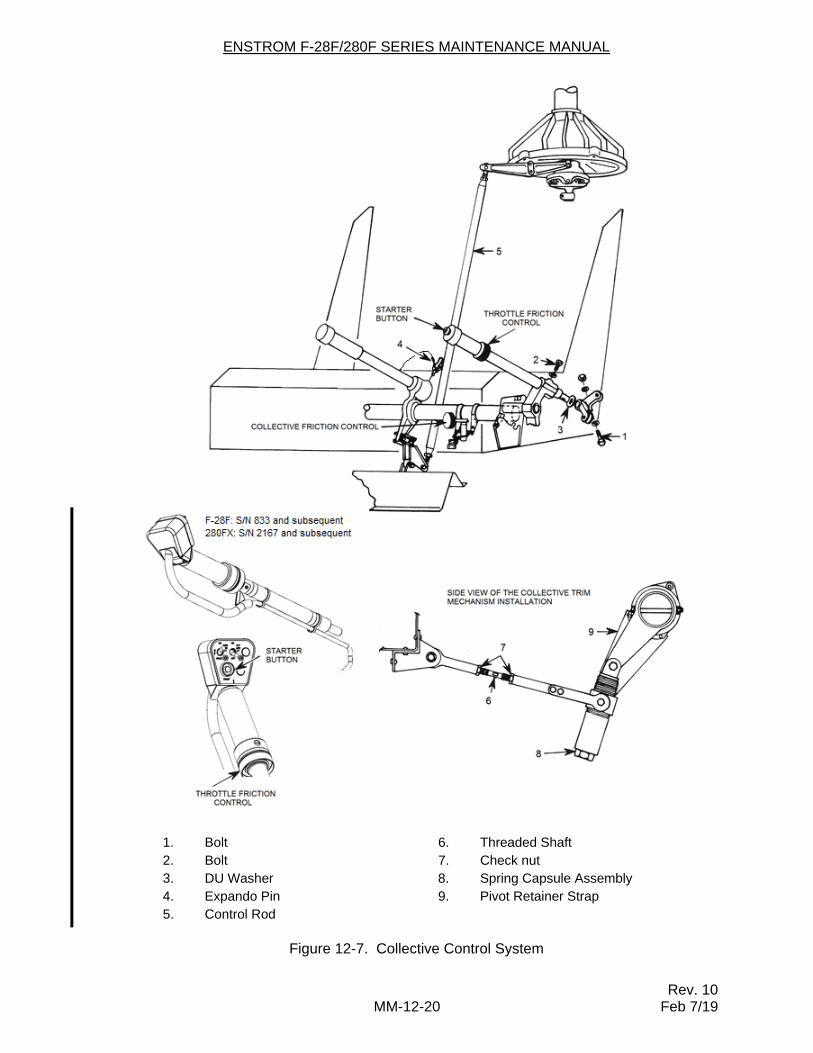
The collective pitch control stick controls rate of climb when pulled upward by increasing the pitch of all three main rotor blades simultaneously and to the same degree. Downward movement of the collective stick decreases the pitch of the blades which decreases lift on the rotor and allows for a controlled descent. The collective pitch control stick is incorporated into the throttle correlator system. This mechanism combines the throttle motion with the collective stick movement such that the proper power inputs are automatically established as the collective stick is moved. The correlator is designed to keep the rotor/engine rpm within the desired green band for the majority of all flight regimes. Friction control is provided on the throttle grip of the collective stick. See Figure 12-7 for locations of the friction control points.
For F-28F S/N 809 through S/N 832 and 280FX S/N 2001 through S/N 2166, the engine starter button is located on the end of the pilot's and co-pilot’s collective sticks (if equipped with dual start). Subsequent S/N are equipped with an illuminated control switch box mounted on the forward end of the collective stick. The control box includes the starter button, and forward and aft landing light switches.
ENSTROM F-28F/280F SERIES MAINTENANCE MANUAL
Rev. 10 MM-12-19 Feb 7/19
2. Pilot’s Collective Control Stick
A. Pilot’s Collective – Removal (Figure 12- 7)
(1) Remove fiberglass cowl over collective stick.
(2) Disconnect electrical wiring, as applicable.
(a) Disconnect starter button wires at the quick disconnect terminals.
(b) (Illuminated collective control only) Disconnect the electrical harness from the electrical connector on the cockpit floor.
(3) Remove bolt (1) connecting throttle bellcrank to collective stick
NOTE: Do not disconnect the co-pilot collective linkage or the correlator linkage attached to the throttle bellcrank.
(4) Cut safety wire and remove bolt (2) from top of collective bellcrank.
95) Remove collective stick from collective and throttle bellcranks. Keep DU washer (3) for reinstallation.
B. Pilot's Collective – Installation
(1) Install collective stick into collective bellcrank and align holes.
(2) Install washer and bolt (2). Torque bolt and safety wire with .032 wire.
(3) Install DU washer (3) on stick with DU side of washer facing forward toward grip.
(4) Install throttle bellcrank and align holes.
(5) Install bolt (1), washers, nut and torque.
(6) Connect electrical wiring, as applicable.
(a) Connect wire terminals for starter button.
(b) (Illuminated collective control only) Connect the electrical harness to the connector on the cockpit floor.
(7) Cycle collective stick up and down and rotate throttle to check freedom of movement.
(8) Install fiberglass cowl and screws.
NOTE: Grease or oil build-up on torque tube may cause collective friction to slip. To remedy this problem spray Loctite 7471 Primer T, or equivalent, into slotted area of collective clamp on torque tube until oil is removed.
ENSTROM F-28F/280F SERIES MAINTENANCE MANUAL
Rev. 10 MM-12-20 Feb 7/19
1. Bolt 6. Threaded Shaft 2. Bolt 7. Check nut 3. DU Washer 8. Spring Capsule Assembly 4. Expando Pin 9. Pivot Retainer Strap 5. Control Rod
Figure 12-7. Collective Control System
ENSTROM F-28F/280F SERIES MAINTENANCE MANUAL
Rev. 10 MM-12-21 Feb 7/19
3. Co-Pilot’s Collective Control Stick (See Figure 12-7)
A. Co-Pilot’s Collective – Removal
(1) (Illuminated collective control only) Disconnect the electrical harness from the electrical connector on the cockpit floor.
(2) Lift tab of the expando pin (4) to a vertical position and pull to remove.
(3) Remove co-pilot's stick from collective bellcrank.
B. Co-Pilot’s Collective – Installation
(1) Align slot in end of collective stick with bolt in collective bellcrank and slide into place.
(2) Align expando pin holes and install pin.
(3) Flip eccentric tab of expando pin to secure.
(4) (Illuminated collective control only) Connect the electrical harness to the connector on the cockpit floor.
NOTE: To adjust tightness of expando pin, loosen set screw on side and rotate pin to required tension. Tighten set screw. The expanding segments must be contained for tight fit.
12-5 COLLECTIVE TRIM SYSTEM (FIGURE 12-9)
NOTE: Refer to Service Information Letter SIL 0184, latest revision, regarding a collective trim system update to simplify collective balance adjustment.
A. Collective Trim
(1) Remove fiberglass seat deck.
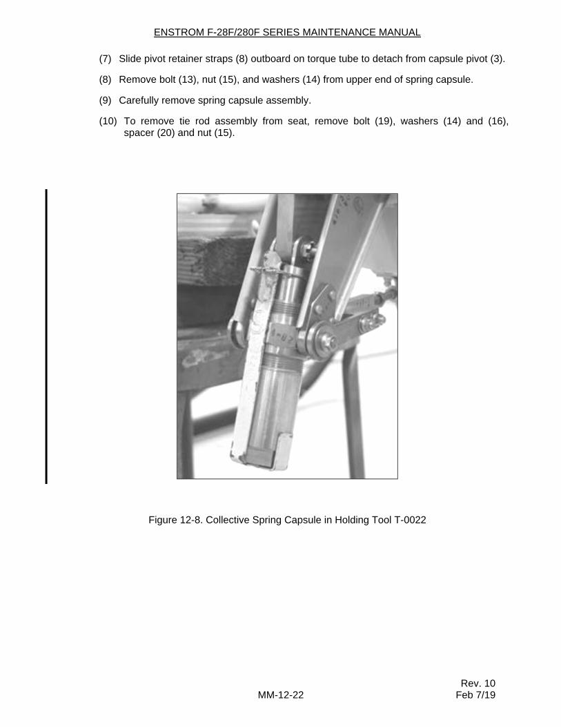
(2) With collective stick down and spring capsule in compressed position, install special tool T-0022 between bottom of hex nut and top of spring housing.
(3) Secure tool T-0022 in position by wrapping upper end with .032 safety wire. See Figure 12-8.
WARNING: With the spring capsule in compressed position there is approximately 180 lbs of force exerted by the springs. Handle with extreme care.
(4) Remove nuts (1) and washers (2) from spring capsule pivot (3).
(5) Remove bolts (5), washers (6), and nuts (7) from brackets (4). Remove brackets.
(6) Remove bolt (9), washers (10) and nut (11) from pivot retainer straps (8). Remove spacer (12).
ENSTROM F-28F/280F SERIES MAINTENANCE MANUAL
Rev. 10 MM-12-22 Feb 7/19
(7) Slide pivot retainer straps (8) outboard on torque tube to detach from capsule pivot (3).
(8) Remove bolt (13), nut (15), and washers (14) from upper end of spring capsule.
(9) Carefully remove spring capsule assembly.
(10) To remove tie rod assembly from seat, remove bolt (19), washers (14) and (16), spacer (20) and nut (15).
Figure 12-8. Collective Spring Capsule in Holding Tool T-0022
ENSTROM F-28F/280F SERIES MAINTENANCE MANUAL SUPPLEMENT
Rev. 10 MM-21-1 Feb 7/19
SECTION 21
ELECTRICAL SYSTEMS AND COMPONENTS
21-1. General – Reference Section 6 for Other Information
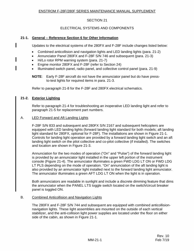
Updates to the electrical systems of the 280FX and F-28F include changes listed below:
Combined anticollision and navigation lights and LED landing lights (para. 21-2) Annunciator Panel 280FX and F-28F S/N 746 and subsequent (para. 21-3) Hi/Lo rotor RPM warning system (para. 21-7) Engine monitor 280FX and F-28F (refer to Section 24) Illuminated switch panel, radio panel, and collective control panel (para. 21-9)
NOTE: Early F-28F aircraft do not have the annunciator panel but do have press-to-test lights for required items in para. 21-3.
Refer to paragraph 21-8 for the F-28F and 280FX electrical schematics.
21-2. Exterior Lighting
Refer to paragraph 21-4 for troubleshooting an inoperative LED landing light and refer to paragraph 21-5 for replacement part numbers.
A. LED Forward and Aft Landing Lights
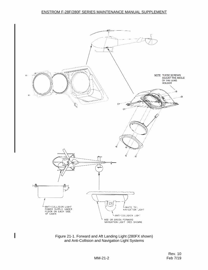
F-28F S/N 833 and subsequent and 280FX S/N 2167 and subsequent helicopters are equipped with LED landing lights (forward landing light standard for both models; aft landing light standard for 280FX, optional for F-28F). The installations are shown in Figure 21-1. Controls for landing light operation are provided by a forward landing light switch and an aft landing light switch on the pilot collective and co-pilot collective (if installed). The switches and location are shown in Figure 21-3.
Annunciation for the two modes of operation (“On” and “Pulse”) of the forward landing light is provided by an annunciator light installed in the upper left portion of the instrument console (Figure 21-4). The annunciator illuminates a green FWD LDG LT ON or FWD LDG LT PLS depending on the mode of operation. “On” annunciation of the aft landing light is also provided by an annunciator light installed next to the forward landing light annunciator. The annunciator illuminates a green AFT LDG LT ON when the light is in operation.
Both annunciators are readable in sunlight and include a discrete dimming feature that dims
the annunciator when the PANEL LTS toggle switch located on the switch/circuit breaker panel is toggled ON.
B. Combined Anticollision and Navigation Lights
The 280FX and F-28F S/N 744 and subsequent are equipped with combined anticollision-navigation lights. These light assemblies are mounted on the outside of each vertical stabilizer, and the anti-collision light power supplies are located under the floor on either side of the cabin, as shown in Figure 21-1.
ENSTROM F-28F/280F SERIES MAINTENANCE MANUAL SUPPLEMENT
Rev. 10 MM-21-2 Feb 7/19
Figure 21-1. Forward and Aft Landing Light (280FX shown) and Anti-Collision and Navigation Light Systems
ENSTROM F-28F/280F SERIES MAINTENANCE MANUAL SUPPLEMENT
Rev. 10 MM-21-3 Feb 7/19
21-3. Annunciator Panel
All of the warning and caution lights for 280FX helicopters are contained in an annunciator panel, which is located at the top of the instrument panel. On early production helicopters, the warning lights include LOW ROTOR RPM, CLUTCH ENGAGE, and LOW FUEL PRESS; the caution lights include OVERBOOST, MRGB CHIP, and TRGB CHIP. On later production helicopters, STARTER RELAY is added to the warning lights and LOW VOLTAGE is added to the caution lights.
The annunciator panel for F-28F helicopters was optional equipment starting with S/N 746. Later F-28F production helicopters incorporated the annunciator panel with all eight segments as standard equipment.
For aircraft equipped with the Hi/Low Rotor RPM Warning System, ROTOR RPM replaces LOW ROTOR RPM in the annunciator panel.
Pressing the “press-to-test” switch at the extreme left of the panel will illuminate all of the indicator lights.
A. Lamp Replacement – Annunciator Panel
Each indicator light contains two lamps. These lamps can be replaced as follows:
(1) Press inward on the right edge of the indicator until indicator opens.
(2) Swing indicator fully open.
(3) Grasp base of lamp firmly and pull lamp out of socket.
(4) Insert replacement lamp and push into place.
(5) Swing indicator closed.
(6) Push on left side of indicator to close.
B. Clutch Disengagement Warning Circuit
The clutch disengagement warning circuit consists of a microswitch on the clutch plate which operates a red warning light in the annunciator panel. This switch is normally closed and completes a circuit to ground when the clutch is disengaged. When the clutch snaps overcenter into the engaged position, an arm on the actuating mechanism opens the switch, which turns out the light. The “normally open” side of this switch arms the rotor rpm circuit.
If the clutch disengagement light does not go out when the clutch is engaged, or if the light comes on in flight, this indicates that the clutch is misrigged or the clutch actuator cable needs servicing. The problem must be found and corrected before the aircraft is returned to service. Press to test warning indicator on F-28F.
C. Low Fuel Pressure Warning Circuit
The low fuel pressure warning circuit comprises a pressure switch in the fuel line between the electric boost pump and the engine-driven fuel pump which activates a red light in the annunciator panel. If the pressure in this fuel line drops below 15 psi, the switch will turn on the red light. This circuit provides the pilot with a warning if the electric boost pump should
ENSTROM F-28F/280F SERIES MAINTENANCE MANUAL SUPPLEMENT
Rev. 10 MM-21-4 Feb 7/19
fail. This light does not indicate the condition of the engine-driven fuel pump. Press to test warning indicator on F-28F.
D. Low Rotor RPM Circuit
The low rotor rpm circuit comprises a magnetic sensor in the main rotor transmission, a signal conditioning unit behind the passenger’s seat, an amber light in the annunciator panel, and a warning horn. The magnetic sensor is located in the forward portion of the main rotor transmission housing. It is positioned to sense the passage of the ring gear teeth. The signal is sent to a small unit located in the backrest of the passenger’s seat. The unit reads the signal from the magnetic sensor and activates the light and the warning horn.
The system is armed by the same switch which activates the clutch disengagement light. Thus, the low rotor rpm light will be on only when the clutch disengaged light is out, and the main rotor rpm is below 334. In addition, the warning horn is wired through a position switch on the collective torque tube such that the horn will not operate with the collective fully down. The horn has a pulsing tone of 2900 Hz at 80-95 decibels.
After the engine is started, the following sequence should occur in the annunciator panel. The red clutch disengagement light will be on until the clutch is engaged. When the clutch snaps into the engaged position, the red clutch disengagement light will go out and the amber low rotor rpm light will turn on. The low rotor rpm light will remain on until the rotor rpm exceeds 334. The horn will sound if the rotor rpm is below 334 and collective is raised off the lower stop.
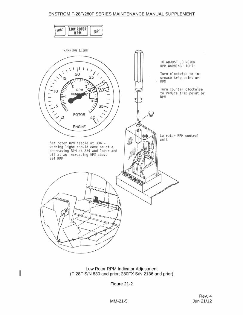
This system is set to trigger the light and horn at 334 rpm ±1 rpm. The system can be adjusted with a potentiometer on the top of the signal conditioning unit. The position of the magnetic sensor was set at the factory and will need no readjustment. Contact Enstrom Product Support for service on the magnetic sensor. For electrical schematic see Diagram 21-4, for RPM adjustment on low rotor indicator see Figure 21-2.
E. Hi/Lo Rotor RPM Circuit
F-28F S/N 831 and subsequent and 280FX S/N 2136 and subsequent are equipped with a Hi/Lo Rotor RPM Circuit. Refer to paragraph 21-7 for maintenance procedures.
F. Overboost Circuit
The overboost circuit consists of a pressure switch behind the instrument panel and connected to the manifold pressure line which activates an amber warning light in the annunciator panel. The light will illuminate between 37.0 and 40.5 in-Hg manifold pressure. The light may be triggered by short pressure pulses which will not appear on the manifold pressure gauge. The manifold pressure gauge is the primary manifold pressure indicator, while the annunciator panel is a secondary indicator. The manifold pressure gauge should be used to determine severity of any overboost.
G. Main and Tail Rotor Gearbox Chip Detectors
The main and tail rotor gearboxes are equipped with magnetic chip detectors which operate amber lights in the annunciator panel. There is a separate circuit and light for each gearbox. When a chip attaches to the chip detector, it completes a circuit to ground, turning on the light. Further information on the chip detectors is included in Sections 19 and 25, which describe the main and tail rotor transmissions, respectively.
ENSTROM F-28F/280F SERIES MAINTENANCE MANUAL SUPPLEMENT
Rev. 4 MM-21-5 Jun 21/12
Low Rotor RPM Indicator Adjustment (F-28F S/N 830 and prior; 280FX S/N 2136 and prior)
Figure 21-2
ENSTROM F-28F/280F SERIES MAINTENANCE MANUAL SUPPLEMENT
Rev. 10 MM-21-6 Feb 7/19
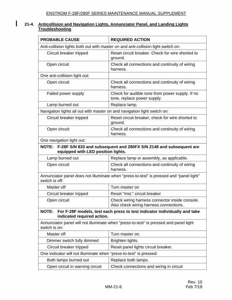
21-4. Anticollision and Navigation Lights, Annunciator Panel, and Landing Lights Troubleshooting
PROBABLE CAUSE REQUIRED ACTION
Anti-collision lights both out with master on and anti-collision light switch on:
Circuit breaker tripped Reset circuit breaker. Check for wire shorted to ground.
Open circuit Check all connections and continuity of wiring harness.
One anti-collision light out:
Open circuit Check all connections and continuity of wiring harness.
Failed power supply Check for audible tone from power supply. If no tone, replace power supply.
Lamp burned out Replace lamp.
Navigation lights all out with master on and navigation light switch on:
Circuit breaker tripped Reset circuit breaker, check for wire shorted to ground.
Open circuit Check all connections and continuity of wiring harness.
One navigation light out:
NOTE: F-28F S/N 833 and subsequent and 280FX S/N 2148 and subsequent are equipped with LED position lights.
Lamp burned out Replace lamp or assembly, as applicable.
Open circuit Check all connections and continuity of wiring harness.
Annunciator panel does not illuminate when “press-to-test” is pressed and “panel light” switch is off:
Master off Turn master on
Circuit breaker tripped Reset “Inst.” circuit breaker
Open circuit Check wiring harness connector inside console. Also check wiring harness connections.
NOTE: For F-28F models, test each press to test indicator individually and take indicated required action.
Annunciator panel will not illuminate when “press-to-test” is pressed and panel light switch is on:
Master off Turn master on.
Dimmer switch fully dimmed Brighten lights.
Circuit breaker tripped Reset panel lights circuit breaker.
One indicator will not illuminate when “press-to-test” is pressed:
Both lamps burned out Replace both lamps.
Open circuit in warning circuit Check connections and wiring in circuit
ENSTROM F-28F/280F SERIES MAINTENANCE MANUAL SUPPLEMENT
Rev. 10 MM-21-7 Feb 7/19
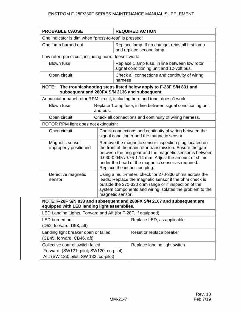
PROBABLE CAUSE REQUIRED ACTION
One indicator is dim when “press-to-test” is pressed:
One lamp burned out Replace lamp. If no change, reinstall first lamp and replace second lamp.
Low rotor rpm circuit, including horn, doesn’t work:
Blown fuse Replace 1 amp fuse, in line between low rotor signal conditioning unit and 12-volt bus.
Open circuit Check all connections and continuity of wiring harness
NOTE: The troubleshooting steps listed below apply to F-28F S/N 831 and subsequent and 280FX S/N 2136 and subsequent.
Annunciator panel rotor RPM circuit, including horn and tone, doesn’t work:
Blown fuse Replace 1 amp fuse, in line between signal conditioning unit and bus.
Open circuit Check all connections and continuity of wiring harness.
ROTOR RPM light does not extinguish:
Open circuit Check connections and continuity of wiring between the signal conditioner and the magnetic sensor.
Magnetic sensor improperly positioned
Remove the magnetic sensor inspection plug located on the front of the main rotor transmission. Ensure the gap between the ring gear and the magnetic sensor is between 0.030-0.045”/0.76-1.14 mm. Adjust the amount of shims under the head of the magnetic sensor as required. Replace the inspection plug.
Defective magnetic sensor
Using a multi-meter, check for 270-330 ohms across the leads. Replace the magnetic sensor if the ohm check is outside the 270-330 ohm range or if inspection of the system components and wiring isolates the problem to the magnetic sensor.
NOTE: F-28F S/N 833 and subsequent and 280FX S/N 2167 and subsequent are equipped with LED landing light assemblies.
LED Landing Lights, Forward and Aft (for F-28F, if equipped)
LED burned out (D52, forward; D53, aft)
Replace LED, as applicable
Landing light breaker open or failed (CB45, forward; CB46, aft)
Reset or replace breaker
Collective control switch failed Forward: (SW121, pilot; SW120, co-pilot) Aft: (SW 133, pilot; SW 132, co-pilot)
Replace landing light switch
ENSTROM F-28F/280F SERIES MAINTENANCE MANUAL SUPPLEMENT
Rev. 10 MM-21-8 Feb 7/19
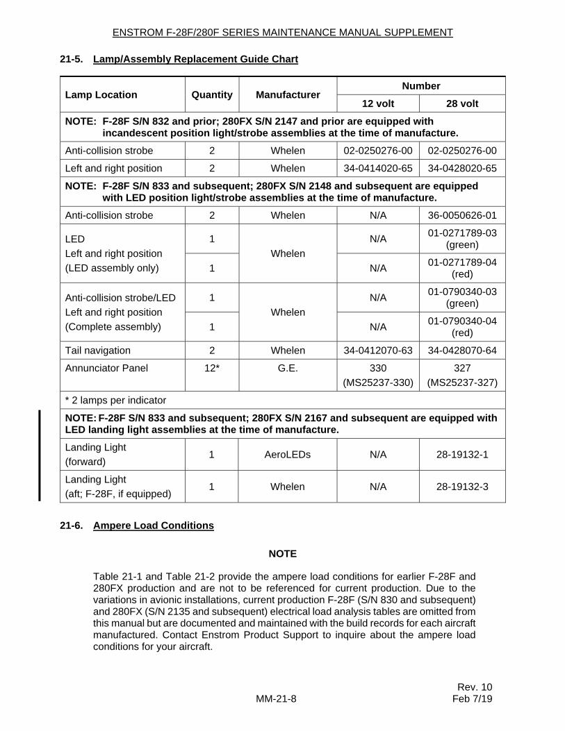
21-5. Lamp/Assembly Replacement Guide Chart
Lamp Location Quantity Manufacturer Number
12 volt 28 volt
NOTE: F-28F S/N 832 and prior; 280FX S/N 2147 and prior are equipped with incandescent position light/strobe assemblies at the time of manufacture.
Anti-collision strobe 2 Whelen 02-0250276-00 02-0250276-00
Left and right position 2 Whelen 34-0414020-65 34-0428020-65
NOTE: F-28F S/N 833 and subsequent; 280FX S/N 2148 and subsequent are equipped with LED position light/strobe assemblies at the time of manufacture.
Anti-collision strobe 2 Whelen N/A 36-0050626-01
LED
Left and right position
(LED assembly only)
1
Whelen
N/A 01-0271789-03
(green)
1 N/A 01-0271789-04
(red)
Anti-collision strobe/LED
Left and right position
(Complete assembly)
1
Whelen
N/A 01-0790340-03
(green)
1 N/A 01-0790340-04
(red)
Tail navigation 2 Whelen 34-0412070-63 34-0428070-64
Annunciator Panel 12* G.E. 330
(MS25237-330)
327
(MS25237-327)
* 2 lamps per indicator
NOTE: F-28F S/N 833 and subsequent; 280FX S/N 2167 and subsequent are equipped with LED landing light assemblies at the time of manufacture.
Landing Light
(forward) 1 AeroLEDs N/A 28-19132-1
Landing Light
(aft; F-28F, if equipped) 1 Whelen N/A 28-19132-3
21-6. Ampere Load Conditions
NOTE
Table 21-1 and Table 21-2 provide the ampere load conditions for earlier F-28F and 280FX production and are not to be referenced for current production. Due to the variations in avionic installations, current production F-28F (S/N 830 and subsequent) and 280FX (S/N 2135 and subsequent) electrical load analysis tables are omitted from this manual but are documented and maintained with the build records for each aircraft manufactured. Contact Enstrom Product Support to inquire about the ampere load conditions for your aircraft.
ENSTROM F-28F/280F SERIES MAINTENANCE MANUAL SUPPLEMENT
Rev. 4 MM-21-13 Jun 21/12
(7) Run up the aircraft in accordance with the operator’s manual. Check the CLUTCH ENGAGE warning light extinguishes and the ROTOR RPM light illuminates when the clutch is engaged.
(8) Increase the power to bring rotor up to 334 rpm and check the ROTOR RPM warning light extinguishes at 333 ± 1 rpm. If the light does not illuminate or extinguish at 333 ± 1 rpm, refer to paragraph D, step (2)a for adjustment.
WARNING
The following test procedure requires flying the aircraft in an autorotation. The test should be conducted by an appropriately rated pilot using appropriate safety precautions.
(9) Fly the aircraft to an altitude and location where an autorotation can be safely performed and recovered.
(10) Enter a stabilized autorotation and allow the rotor RPM to build to the upper red line, 385 RPM
CAUTION
Rotor RPM can build very quickly in autorotation. Use care when approaching the upper red line.
NOTE
The aircraft will have to be moderately heavy to achieve a high enough autorotation RPM. An accelerated maneuver, such as a turn or flare, may also be required to increase the RPM.
(11) Check that the ROTOR RPM warning light illuminates above 385 ± 2 RPM. Do not allow the rotor RPM to exceed 390.
NOTE
If the collective is fully down, the horn and tone will not activate.
(12) Bring RPM down. Check that the ROTOR RPM warning light extinguishes below 385 ± 2 RPM.
(13) If the warning light does not illuminate or extinguish at 385 ± 2 RPM, refer to paragraph D, step (2)b for adjustment.
(14) Check the operation of the ROTOR RPM and CLUTCH ENGAGE warning lights during the shutdown procedure
ENSTROM F-28F/280F SERIES MAINTENANCE MANUAL SUPPLEMENT
Rev. 10 MM-21-14 Feb 7/19
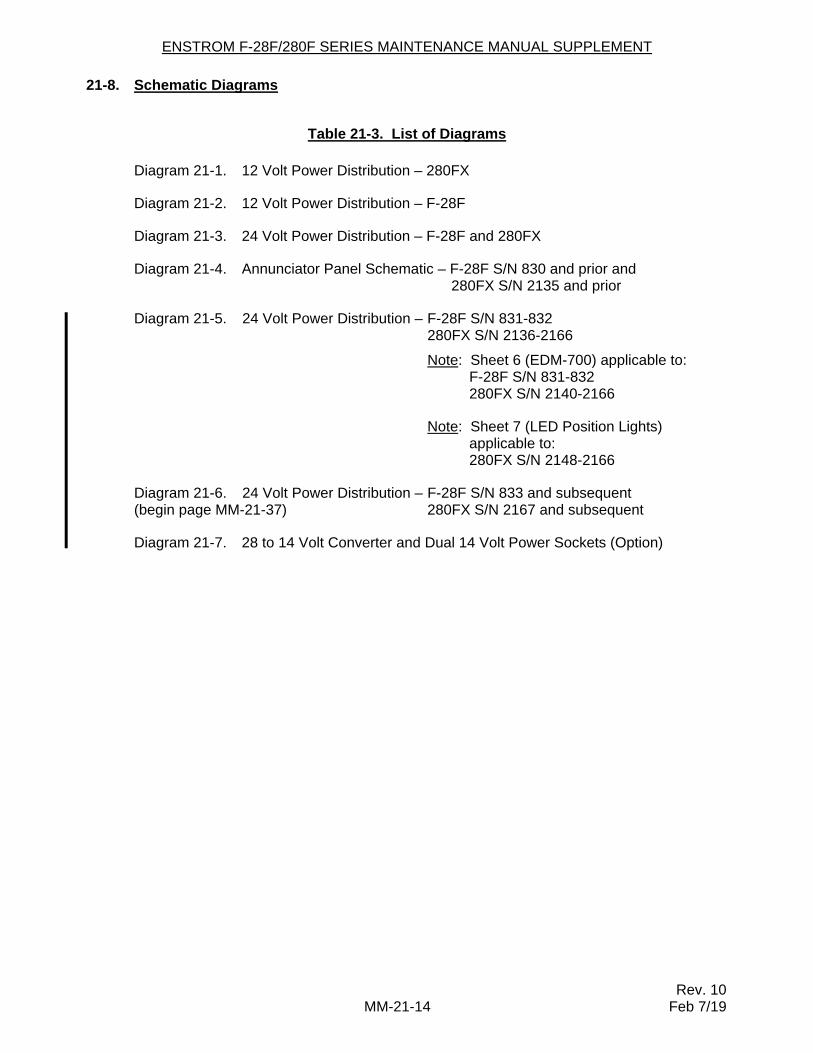
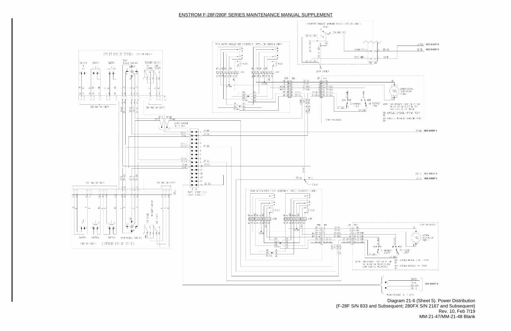
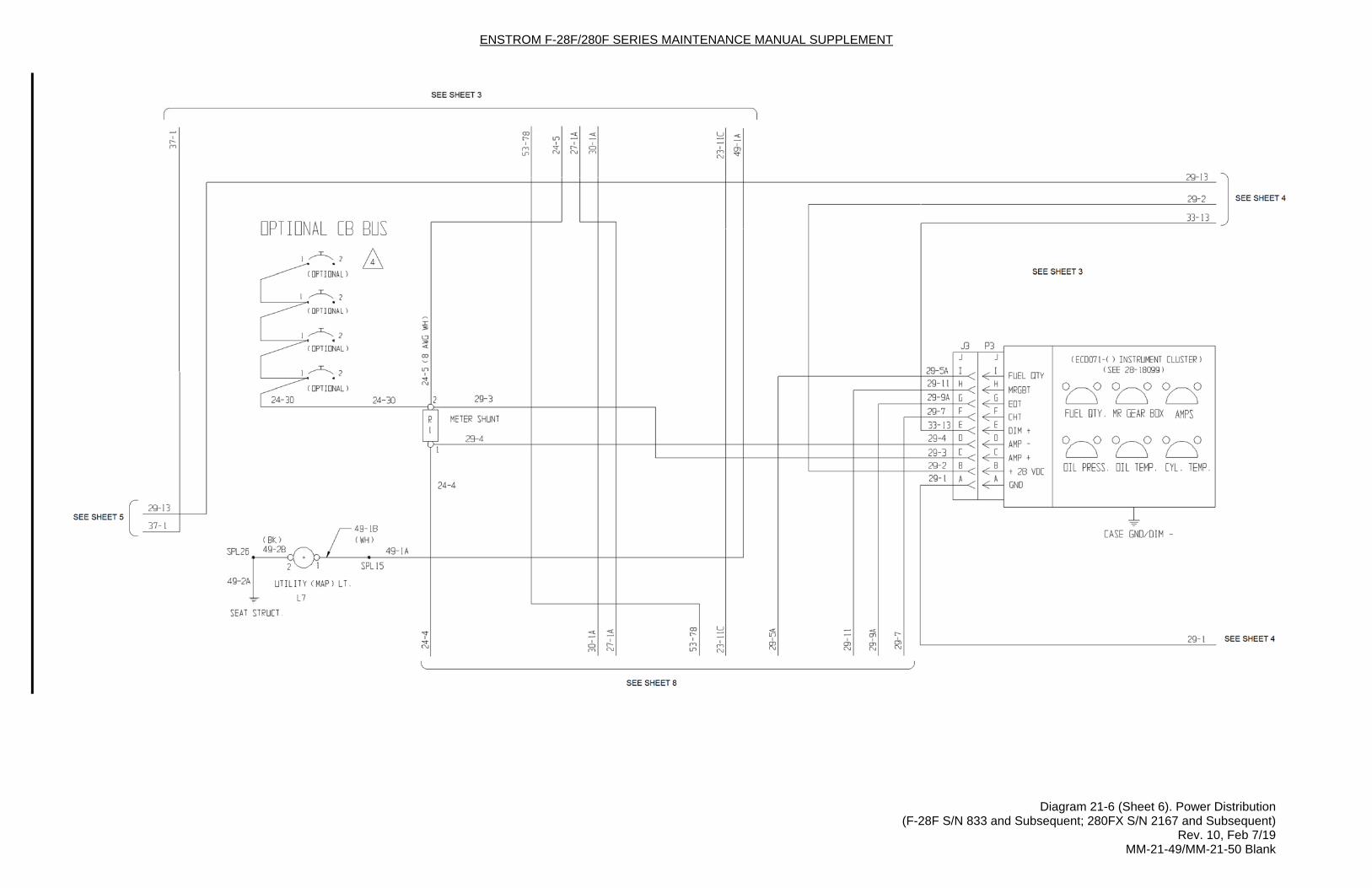
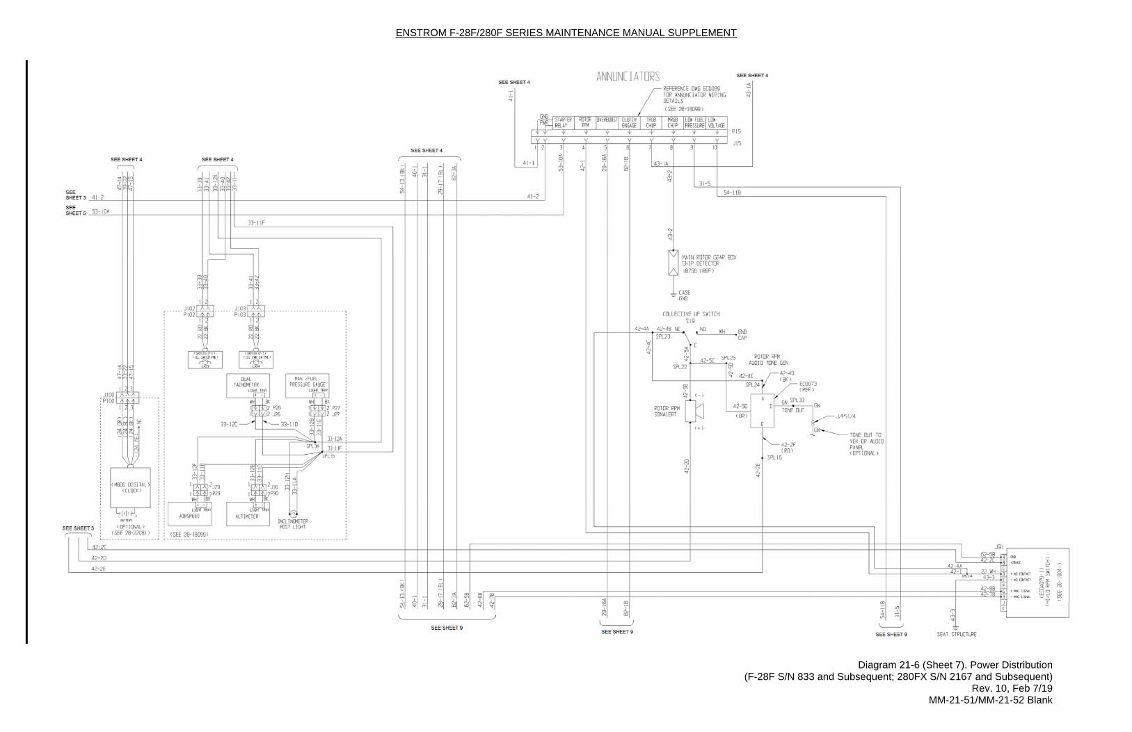
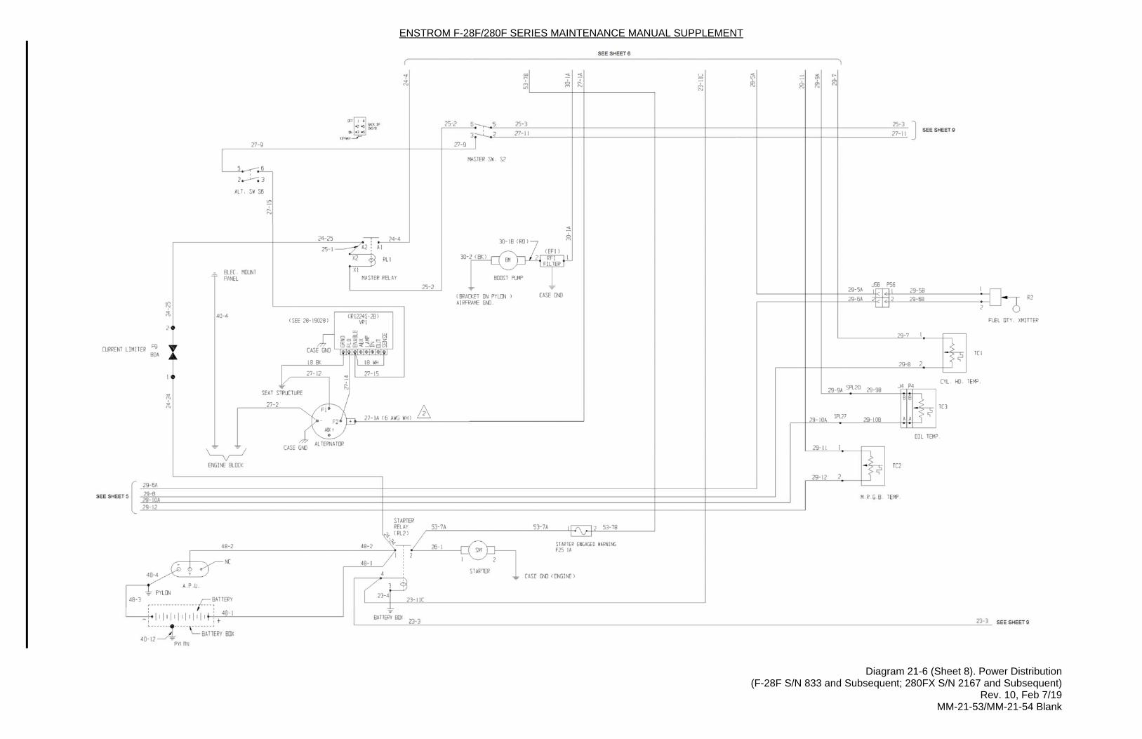
21-8. Schematic Diagrams
Table 21-3. List of Diagrams
Diagram 21-1. 12 Volt Power Distribution – 280FX
Diagram 21-2. 12 Volt Power Distribution – F-28F
Diagram 21-3. 24 Volt Power Distribution – F-28F and 280FX
Diagram 21-4. Annunciator Panel Schematic – F-28F S/N 830 and prior and 280FX S/N 2135 and prior
Diagram 21-5. 24 Volt Power Distribution – F-28F S/N 831-832 280FX S/N 2136-2166
Note: Sheet 6 (EDM-700) applicable to: F-28F S/N 831-832 280FX S/N 2140-2166
Note: Sheet 7 (LED Position Lights) applicable to:
280FX S/N 2148-2166
Diagram 21-6. 24 Volt Power Distribution – F-28F S/N 833 and subsequent (begin page MM-21-37) 280FX S/N 2167 and subsequent
Diagram 21-7. 28 to 14 Volt Converter and Dual 14 Volt Power Sockets (Option)
ENSTROM F-28F/280F SERIES MAINTENANCE MANUAL SUPPLEMENT
Rev. 10 MM-21-33 Feb 7/19
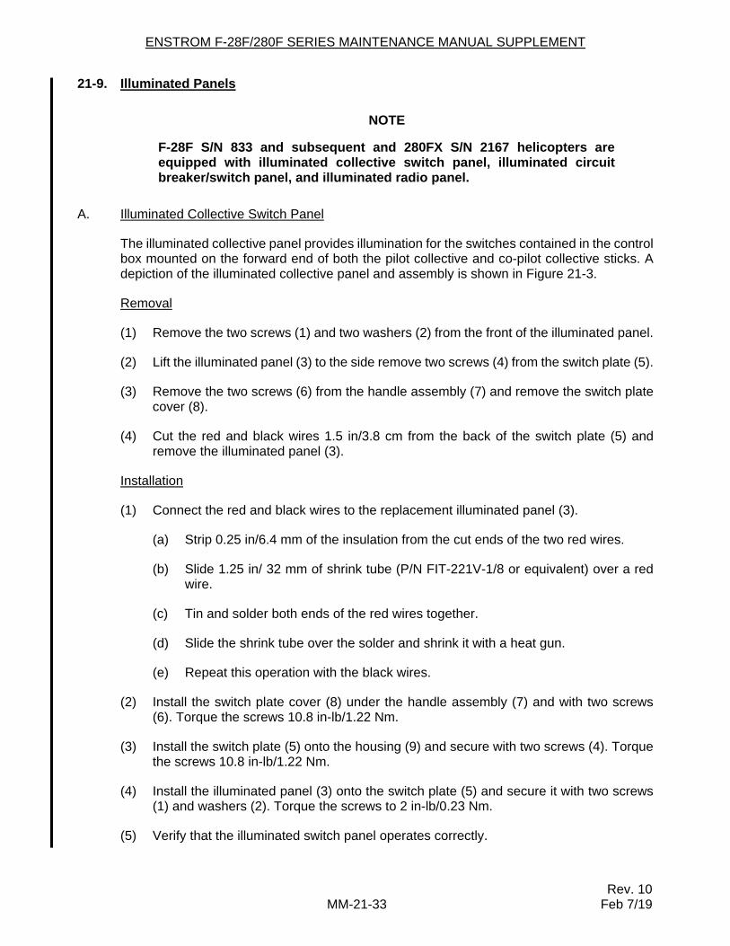
21-9. Illuminated Panels
NOTE
F-28F S/N 833 and subsequent and 280FX S/N 2167 helicopters are equipped with illuminated collective switch panel, illuminated circuit breaker/switch panel, and illuminated radio panel.
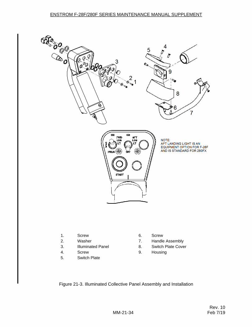
A. Illuminated Collective Switch Panel
The illuminated collective panel provides illumination for the switches contained in the control box mounted on the forward end of both the pilot collective and co-pilot collective sticks. A depiction of the illuminated collective panel and assembly is shown in Figure 21-3.
Removal
(1) Remove the two screws (1) and two washers (2) from the front of the illuminated panel.
(2) Lift the illuminated panel (3) to the side remove two screws (4) from the switch plate (5).
(3) Remove the two screws (6) from the handle assembly (7) and remove the switch plate cover (8).
(4) Cut the red and black wires 1.5 in/3.8 cm from the back of the switch plate (5) and remove the illuminated panel (3).
Installation
(1) Connect the red and black wires to the replacement illuminated panel (3).
(a) Strip 0.25 in/6.4 mm of the insulation from the cut ends of the two red wires.
(b) Slide 1.25 in/ 32 mm of shrink tube (P/N FIT-221V-1/8 or equivalent) over a red wire.
(c) Tin and solder both ends of the red wires together.
(d) Slide the shrink tube over the solder and shrink it with a heat gun.
(e) Repeat this operation with the black wires.
(2) Install the switch plate cover (8) under the handle assembly (7) and with two screws (6). Torque the screws 10.8 in-lb/1.22 Nm.
(3) Install the switch plate (5) onto the housing (9) and secure with two screws (4). Torque the screws 10.8 in-lb/1.22 Nm.
(4) Install the illuminated panel (3) onto the switch plate (5) and secure it with two screws (1) and washers (2). Torque the screws to 2 in-lb/0.23 Nm.
(5) Verify that the illuminated switch panel operates correctly.
ENSTROM F-28F/280F SERIES MAINTENANCE MANUAL SUPPLEMENT
Rev. 10 MM-21-34 Feb 7/19
1. Screw 6. Screw 2. Washer 7. Handle Assembly 3. Illuminated Panel 8. Switch Plate Cover 4. Screw 9. Housing 5. Switch Plate
Figure 21-3. Illuminated Collective Panel Assembly and Installation
ENSTROM F-28F/280F SERIES MAINTENANCE MANUAL SUPPLEMENT
Rev. 10 MM-21-35 Feb 7/19
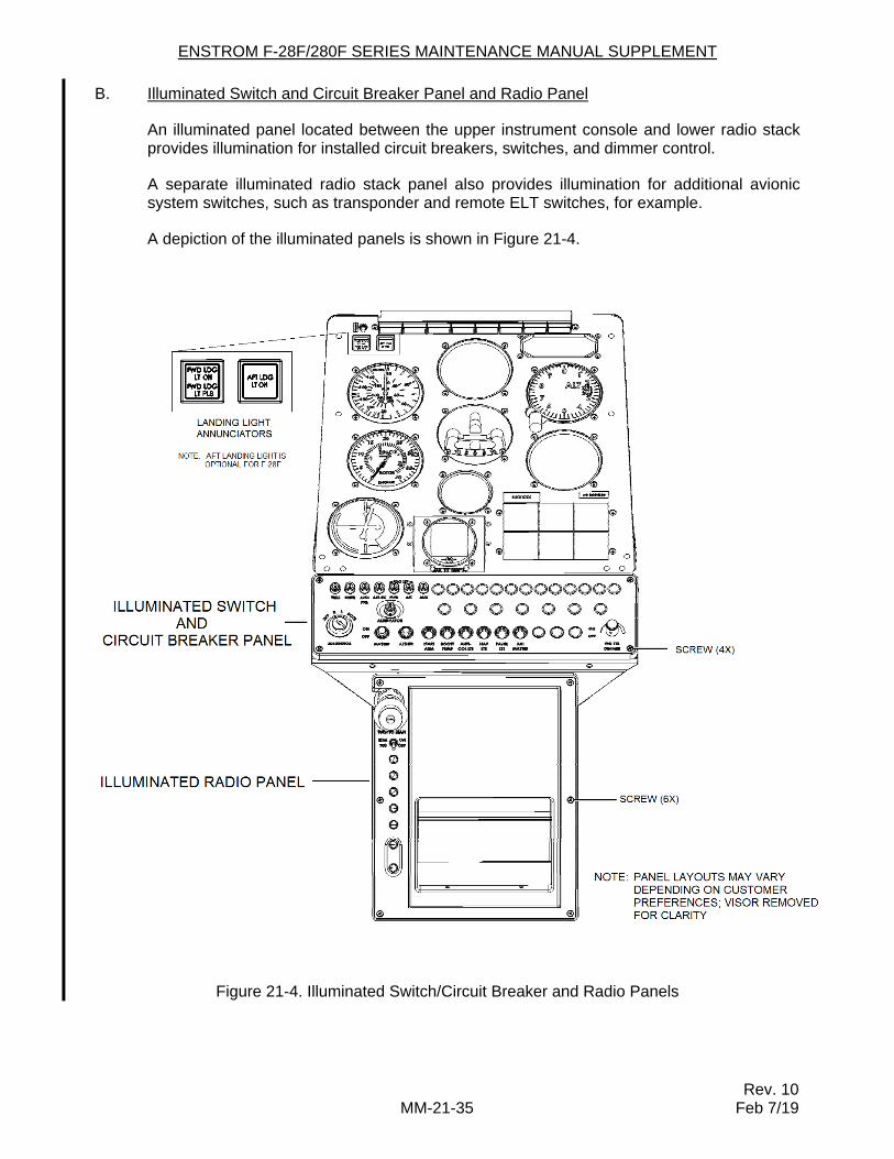
B. Illuminated Switch and Circuit Breaker Panel and Radio Panel
An illuminated panel located between the upper instrument console and lower radio stack provides illumination for installed circuit breakers, switches, and dimmer control.
A separate illuminated radio stack panel also provides illumination for additional avionic system switches, such as transponder and remote ELT switches, for example.
A depiction of the illuminated panels is shown in Figure 21-4.
Figure 21-4. Illuminated Switch/Circuit Breaker and Radio Panels
ENSTROM F-28F/280F SERIES MAINTENANCE MANUAL SUPPLEMENT
Rev. 10 MM-21-36 Feb 7/19
Removal – Switch and circuit breaker panel:
(1) Remove power from the aircraft.
(2) Center all toggle switches and remove the PNL LTS DIMMER knob.
(3) Remove the screws (4X) (Figure 21-4).
(4) Lift the panel away from the console to access the electrical connector.
(5) Disconnect the electrical connector and remove the panel.
Removal – Radio panel:
(1) Remove power from the aircraft.
(2) Center all toggle switches.
(3) Remove the screws (6X) (Figure 21-4).
(4) Lift the panel away from the console to access the electrical connector.
(5) Disconnect the electrical connector and remove the panel.
Installation – Switch and circuit breaker panel and radio panel:
(1) Connect the electrical connector.
(2) Install the panel in position.
(3) Install the screws, as required (Figure 21-4).
(4) Install the dimmer knob, if required, and toggle all switches to OFF or as required, as applicable.
(5) Apply aircraft power and check the illuminated panel operation.
ENSTROM F-28F/280F SERIES MAINTENANCE MANUAL SUPPLEMENT
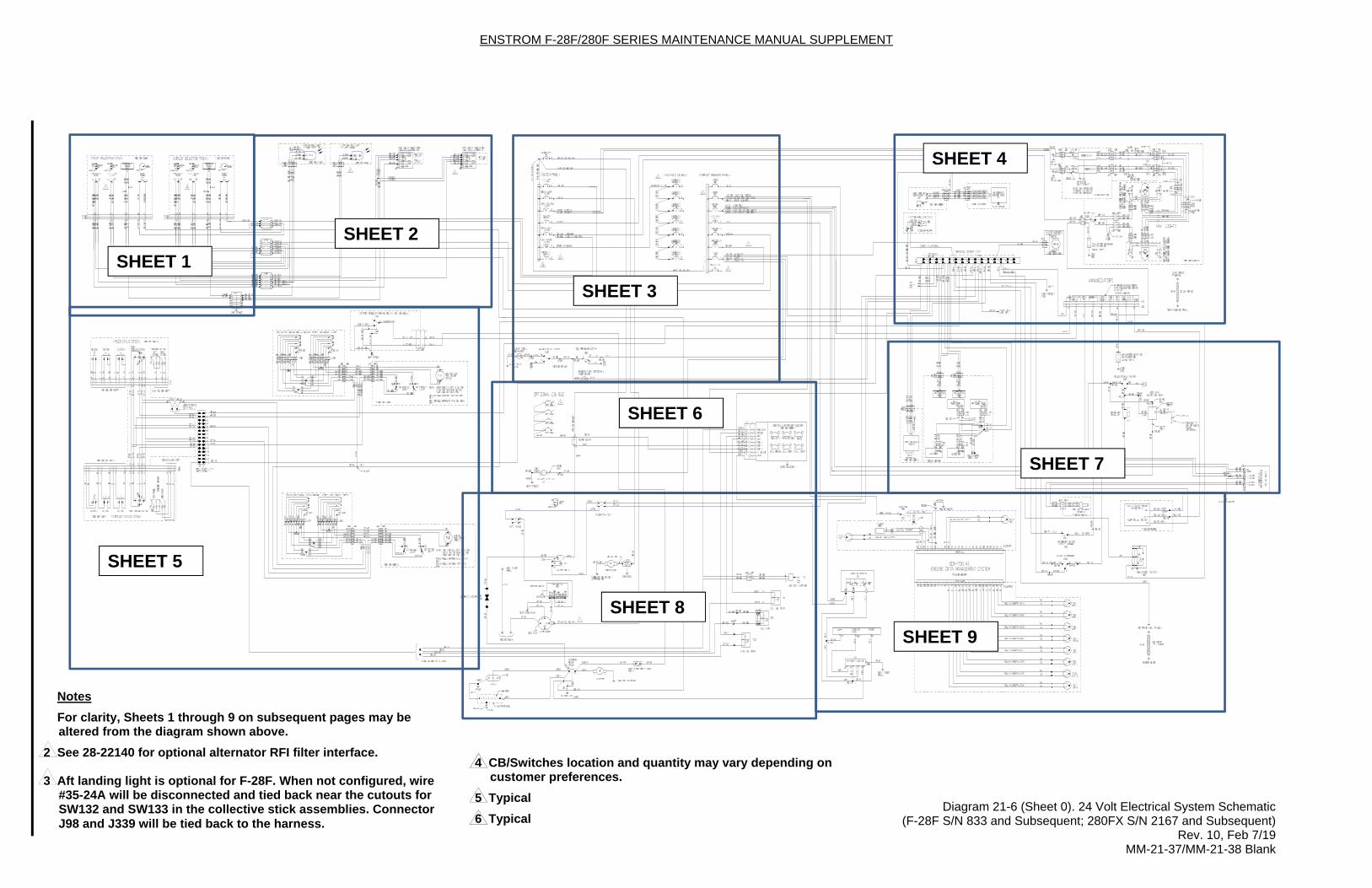
Diagram 21-6 (Sheet 0). 24 Volt Electrical System Schematic (F-28F S/N 833 and Subsequent; 280FX S/N 2167 and Subsequent) Rev. 10, Feb 7/19 MM-21-37/MM-21-38 Blank
SHEET 1
SHEET 2
SHEET 3
SHEET 4
SHEET 5
SHEET 6
SHEET 8
SHEET 7
SHEET 9
Notes
For clarity, Sheets 1 through 9 on subsequent pages may be altered from the diagram shown above.
2 See 28-22140 for optional alternator RFI filter interface. 3 Aft landing light is optional for F-28F. When not configured, wire
#35-24A will be disconnected and tied back near the cutouts for SW132 and SW133 in the collective stick assemblies. Connector J98 and J339 will be tied back to the harness.
4 CB/Switches location and quantity may vary depending on customer preferences.
5 Typical
6 Typical

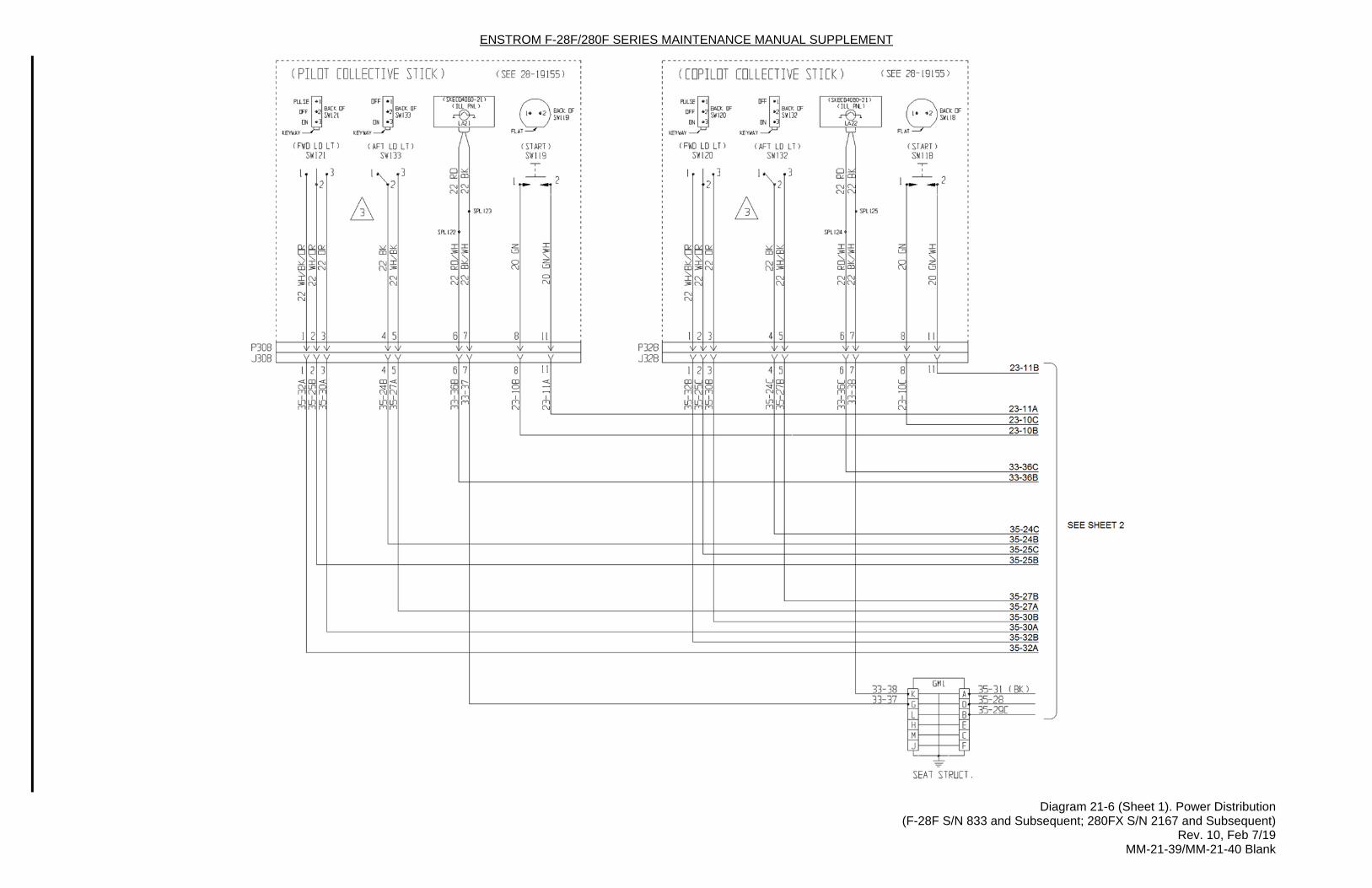
ENSTROM F-28F/280F SERIES MAINTENANCE MANUAL SUPPLEMENT
Diagram 21-6 (Sheet 1). Power Distribution (F-28F S/N 833 and Subsequent; 280FX S/N 2167 and Subsequent) Rev. 10, Feb 7/19 MM-21-39/MM-21-40 Blank

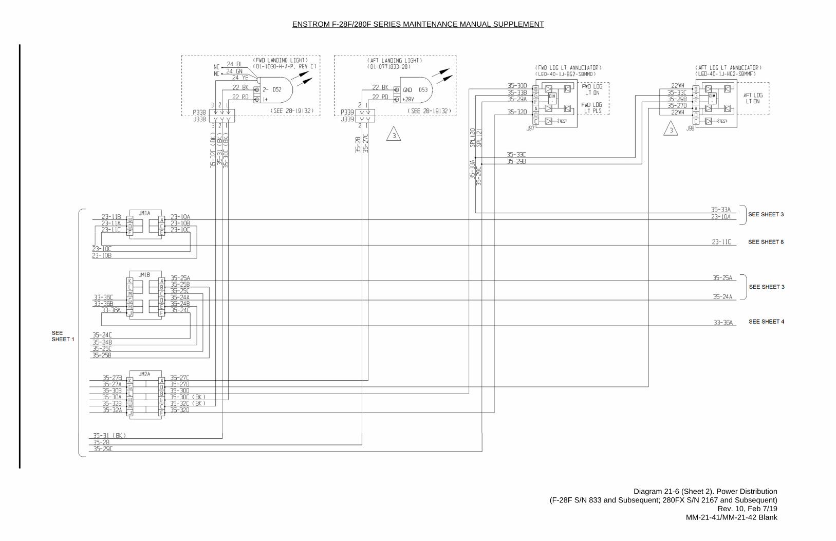
ENSTROM F-28F/280F SERIES MAINTENANCE MANUAL SUPPLEMENT
Diagram 21-6 (Sheet 2). Power Distribution (F-28F S/N 833 and Subsequent; 280FX S/N 2167 and Subsequent) Rev. 10, Feb 7/19 MM-21-41/MM-21-42 Blank

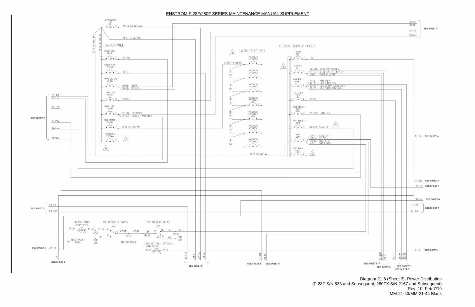
ENSTROM F-28F/280F SERIES MAINTENANCE MANUAL SUPPLEMENT
Diagram 21-6 (Sheet 3). Power Distribution (F-28F S/N 833 and Subsequent; 280FX S/N 2167 and Subsequent) Rev. 10, Feb 7/19 MM-21-43/MM-21-44 Blank

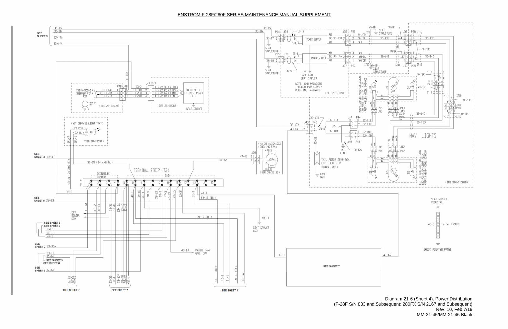
ENSTROM F-28F/280F SERIES MAINTENANCE MANUAL SUPPLEMENT
Diagram 21-6 (Sheet 4). Power Distribution (F-28F S/N 833 and Subsequent; 280FX S/N 2167 and Subsequent) Rev. 10, Feb 7/19 MM-21-45/MM-21-46 Blank

ENSTROM F-28F/280F SERIES MAINTENANCE MANUAL SUPPLEMENT
Diagram 21-6 (Sheet 5). Power Distribution (F-28F S/N 833 and Subsequent; 280FX S/N 2167 and Subsequent) Rev. 10, Feb 7/19 MM-21-47/MM-21-48 Blank

ENSTROM F-28F/280F SERIES MAINTENANCE MANUAL SUPPLEMENT
Diagram 21-6 (Sheet 6). Power Distribution (F-28F S/N 833 and Subsequent; 280FX S/N 2167 and Subsequent) Rev. 10, Feb 7/19 MM-21-49/MM-21-50 Blank

ENSTROM F-28F/280F SERIES MAINTENANCE MANUAL SUPPLEMENT
Diagram 21-6 (Sheet 7). Power Distribution (F-28F S/N 833 and Subsequent; 280FX S/N 2167 and Subsequent) Rev. 10, Feb 7/19 MM-21-51/MM-21-52 Blank

ENSTROM F-28F/280F SERIES MAINTENANCE MANUAL SUPPLEMENT
Diagram 21-6 (Sheet 8). Power Distribution (F-28F S/N 833 and Subsequent; 280FX S/N 2167 and Subsequent) Rev. 10, Feb 7/19 MM-21-53/MM-21-54 Blank

ENSTROM F-28F/280F SERIES MAINTENANCE MANUAL SUPPLEMENT
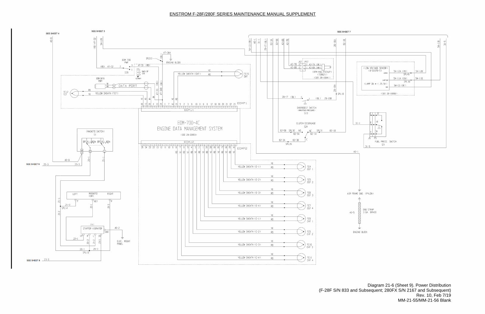
Diagram 21-6 (Sheet 9). Power Distribution (F-28F S/N 833 and Subsequent; 280FX S/N 2167 and Subsequent) Rev. 10, Feb 7/19 MM-21-55/MM-21-56 Blank

ENSTROM F-28F/280F SERIES MAINTENANCE MANUAL SUPPLEMENT
Rev. 10 MM-21-57 Feb 7/19
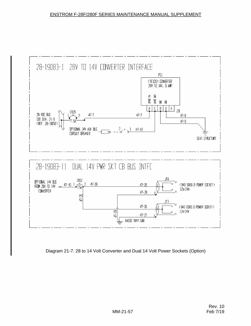
Diagram 21-7. 28 to 14 Volt Converter and Dual 14 Volt Power Sockets (Option)

ENSTROM F-28F/280F SERIES MAINTENANCE MANUAL SUPPLEMENT
Rev. 10 MM-21-58 Feb 7/19
INTENTIONALLY LEFT BLANK
ENSTROM F-28F/280F SERIES MAINTENANCE MANUAL SUPPLEMENT
Rev. 10 MM-24-7 Feb 7/19
24-6. Clock
A digital clock, if equipped, may be installed in the switch and circuit breaker panel or the instrument panel (F-28F S/N 833 and subsequent; 280FX S/N 2167 and subsequent). The clock is powered by an internal alkaline battery which should be replaced every 12 months. Vendor information is provided in Table 24-3.
Refer to paragraph 7-18 for removal and installation instructions.
Refer to the vendor’s published literature for clock specifications and operation (see Table 24-3).
24-7. Outside Air Temperature Indicator (OAT)
OAT indication is shown by the numeric display on the engine monitoring system (GEM or EDM). The interior, top cabin mounted outside air temperature indicator was discontinued for F-28F S/N 832 and subsequent and 280FX S/N 2147 and subsequent.
Refer to the vendor’s published manuals for OAT display (see Table 24-3).
24-8. Magnetic Compass
NOTE
Due to improved performance, F-28F S/N 833 and subsequent and 280FX S/N 2167 and subsequent helicopters are equipped from the factory with a SIRS Navigation Aircraft Compass.
The compass installation is mounted to the center windshield post and includes the correction
card adjacent the compass. The compass may feature a fluorescent card legend, LED illumination, and silicone card damping.
Power for illumination is provided by the PNL LT switch and brightness may be controlled with the DIMMER PANEL LT knob.
Refer to paragraph 7-18 for removal and installation instructions.
Refer to paragraph 7-19 for inspection requirements.
In the event the compass must be replaced, refer to the manufacturer’s installation instructions. Vendor information is provided in Table 24-3.
ENSTROM F-28F/280F SERIES MAINTENANCE MANUAL SUPPLEMENT
Rev. 10 MM-24-8 Feb 7/19
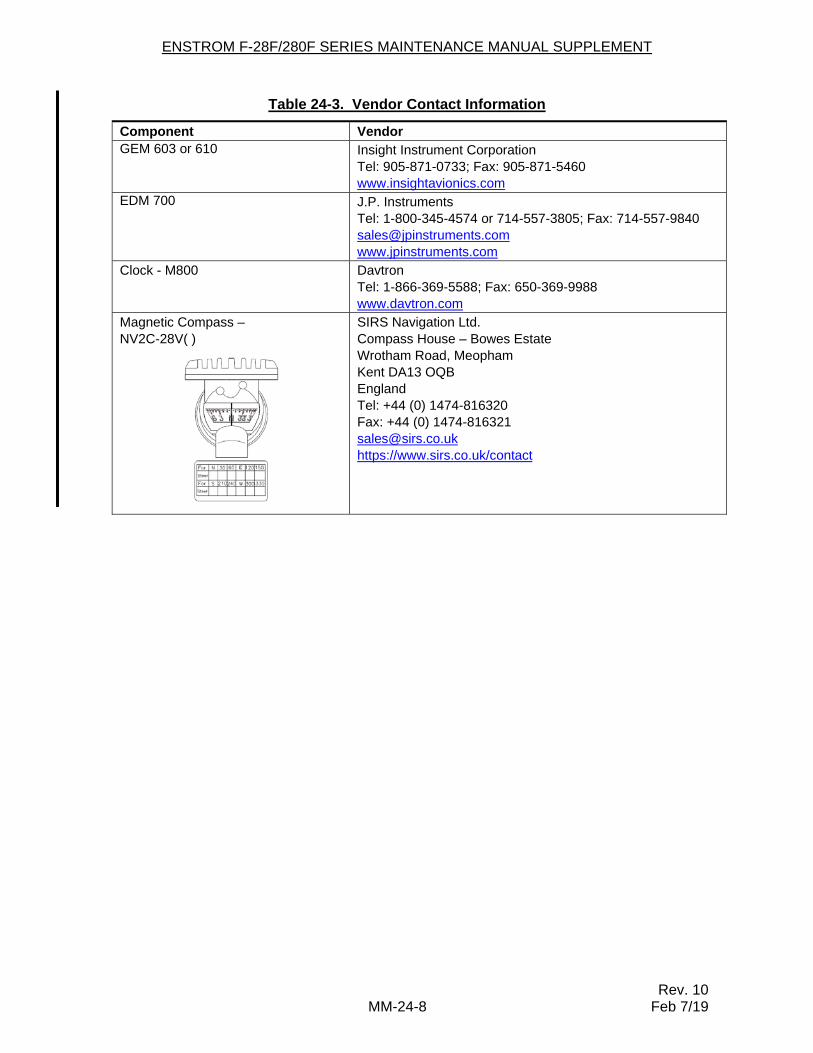
Table 24-3. Vendor Contact Information
Component Vendor GEM 603 or 610 Insight Instrument Corporation
Tel: 905-871-0733; Fax: 905-871-5460 www.insightavionics.com
EDM 700 J.P. Instruments Tel: 1-800-345-4574 or 714-557-3805; Fax: 714-557-9840 [email protected] www.jpinstruments.com
Clock - M800 Davtron Tel: 1-866-369-5588; Fax: 650-369-9988 www.davtron.com
Magnetic Compass – NV2C-28V( )
SIRS Navigation Ltd. Compass House – Bowes Estate Wrotham Road, Meopham Kent DA13 OQB England Tel: +44 (0) 1474-816320 Fax: +44 (0) 1474-816321 [email protected] https://www.sirs.co.uk/contact