Embed Size (px)
Citation preview

Enterprise Information Architecture Patterns forGovernment
Rute Sofia Caronho Lemos
Thesis to obtain the Master of Science Degree in
Information Systems and Computer Engineering
Supervisor: Prof. André Ferreira Ferrão Couto e Vasconcelos
Examination CommitteeChairperson:
Supervisor:Member of the Committee:
Prof. José Carlos Martins DelgadoProf. André Ferreira Ferrão Couto e VasconcelosProf. José Luís Brinquete Borbinha
October 2016

Acknowledgments
I owe my deepest gratitude to Professor André Vasconcelos. This dissertation would not have beenpossible without his valuable guidance and expertise and it was an honor to have him as my advisor.
I am also thankful to Lisdália Sanches and Marco Pedro from AMA for the support given in my thesisand for their participation in reunions and revision of my results, thus adding value to this dissertation.
I am indebted to my family for supporting me throughout all my studies at university. I would like todeeply thank and dedicate this dissertation to my grandmother Maria de Jesus Caronho, my mother IldaCaronho, my brother Hugo and my father António Lemos for all their love, support and dedication.
A special dedication to my grandfather Vitor Manuel da Fonseca Caronho, who passed away lastyear. He has always supported and guided me with much love and to who forever I will always beindebted.
I would also like to thank the scholarship given by INESC-ID.Finally, I would like to show my gratitude to my colleagues and friends that directly or indirectly helped
me during this dissertation.
i

In memory of my dear grandfather, Vitor Caronho. I owe everything to
you and grandma. Thank you for always being there for me.
ii
Abstract
Currently, there isn’t a specific method to find patterns for Enterprise Information Architecture in thearea of Government. The goal of this work is to investigate the use of patterns and anti-patterns andpropose a method to generate Enterprise Information Architecture patterns catalog for the PortugueseGovernment. Using patterns the organizations are expected to document proven practice solutions forrecurring problems in a given context, in order to be used when creating new Enterprise InformationArchitecture in future projects.
To accomplish that, we propose a five-phased method to generate patterns which involves the se-lection of Enterprise Information Architecture documents with similar context, the comparison betweenthem using an iterative process with weighted similarity rules, the generation of the pattern, classifyingit as a pattern or anti-pattern, and its documentation.
For demonstration purposes, an example based on a practical case is shown. It is also demonstratedthe use of the method in the specific case of a Portuguese Government Agency, AMA.
Evaluation was made using interviews and also by comparison with other Enterprise InformationArchitecture approaches.
Keywords: Enterprise Information Architecture, Patterns, Informational Entities, PatternDocumentation.
iii
Resumo
Atualmente, não existe um método específico de descoberta de padrões de Arquitetura de InformaçãoEmpresarial na área da Administração Pública. O objectivo deste trabalho é investigar o uso de padrõese anti-padrões e propor um método para gerar um catálogo de padrões de Arquitetura de InformaçõesEmpresariais para a Administração Pública Portuguesa. Usando padrões, é expectável que a organi-zação documente práticas de soluções comprovadas num dado contexto, de forma a serem usados emfuturos projectos que envolvam a criação de uma nova Arquitetura de Informação Empresarial.
Para se atingir o objectivo mencionado, propomos um método de cinco fases que envolve a seleçãode documentos de Arquitetura de Informações Empresariais com contexto semelhante entre si, a com-paração entre essas arquiteturas usando um processo iterativo com pesos nas regras de similaridade,a geração dos padrões, a classificação como padrão ou anti-padrão e a documentação dos mesmos.
Para demonstrar o método, um exemplo baseado num caso prático é mostrado. Também é demons-trado o método numa agência da Administração Portuguesa, a AMA.
A avaliação foi feita recorrendo à comparação com outras frameworks de Arquiteturas de InformaçãoEmpresariais.
Palavras-chave: Arquitectura Informacional, Padrões, Entidades Informacionais, Documentação dePadrões.
iv
Contents
List of Tables vii
List of Figures viii
Acronyms ix
1 Introduction 11.1 Motivation . . . . . . . . . . . . . . . . . . . . . . . . . . . . . . . . . . . . . . . . . . . . . 11.2 Problem Statement . . . . . . . . . . . . . . . . . . . . . . . . . . . . . . . . . . . . . . . . 21.3 Contributions . . . . . . . . . . . . . . . . . . . . . . . . . . . . . . . . . . . . . . . . . . . 31.4 Research Method . . . . . . . . . . . . . . . . . . . . . . . . . . . . . . . . . . . . . . . . 31.5 Document Structure . . . . . . . . . . . . . . . . . . . . . . . . . . . . . . . . . . . . . . . 5
2 Related Work 62.1 Enterprise Architecture . . . . . . . . . . . . . . . . . . . . . . . . . . . . . . . . . . . . . 62.2 Information Architecture . . . . . . . . . . . . . . . . . . . . . . . . . . . . . . . . . . . . . 72.3 Enterprise Information Architecture . . . . . . . . . . . . . . . . . . . . . . . . . . . . . . . 92.4 Data Modeling . . . . . . . . . . . . . . . . . . . . . . . . . . . . . . . . . . . . . . . . . . 11
2.4.1 UML . . . . . . . . . . . . . . . . . . . . . . . . . . . . . . . . . . . . . . . . . . . . 112.4.2 Entity-Relationship Modeling . . . . . . . . . . . . . . . . . . . . . . . . . . . . . . 122.4.3 Comparison between ER Model and UML . . . . . . . . . . . . . . . . . . . . . . . 12
2.5 Pattern . . . . . . . . . . . . . . . . . . . . . . . . . . . . . . . . . . . . . . . . . . . . . . 132.5.1 Documentation of Patterns . . . . . . . . . . . . . . . . . . . . . . . . . . . . . . . 13
2.6 Work developed by AMA . . . . . . . . . . . . . . . . . . . . . . . . . . . . . . . . . . . . . 142.7 Reverse Engineering . . . . . . . . . . . . . . . . . . . . . . . . . . . . . . . . . . . . . . . 15
2.7.1 Removal of tables exclusive to DBs . . . . . . . . . . . . . . . . . . . . . . . . . . . 152.7.2 Removal of attributes exclusive to DBs . . . . . . . . . . . . . . . . . . . . . . . . . 152.7.3 Removal of Foreign Keys . . . . . . . . . . . . . . . . . . . . . . . . . . . . . . . . 162.7.4 Removal of Tables which contain only exclusive Foreign Keys . . . . . . . . . . . . 16
2.8 Other related work . . . . . . . . . . . . . . . . . . . . . . . . . . . . . . . . . . . . . . . . 172.9 Discussion . . . . . . . . . . . . . . . . . . . . . . . . . . . . . . . . . . . . . . . . . . . . 20
3 Solution Proposal 213.1 1st Phase - Gathering of EIA documents . . . . . . . . . . . . . . . . . . . . . . . . . . . . 233.2 2nd Phase - Comparison of the EIA . . . . . . . . . . . . . . . . . . . . . . . . . . . . . . . 23
3.2.1 Representation of EIA in a Relational Databases Model . . . . . . . . . . . . . . . 273.2.2 Representation of EIA in an UML Model . . . . . . . . . . . . . . . . . . . . . . . . 273.2.3 Representation of EIA both in Relational Databases and UML Models . . . . . . . 28
v
3.3 3rd Phase - Generation of the pattern . . . . . . . . . . . . . . . . . . . . . . . . . . . . . . 303.3.1 Pattern Generation Rules . . . . . . . . . . . . . . . . . . . . . . . . . . . . . . . . 30
3.3.1.1 Pattern Generation Rule 1 . . . . . . . . . . . . . . . . . . . . . . . . . . 303.3.1.2 Pattern Generation Rule 2 . . . . . . . . . . . . . . . . . . . . . . . . . . 303.3.1.3 Pattern Generation Rule 3 . . . . . . . . . . . . . . . . . . . . . . . . . . 313.3.1.4 Pattern Generation Rule 4 . . . . . . . . . . . . . . . . . . . . . . . . . . 323.3.1.5 Pattern Generation Rule 5 . . . . . . . . . . . . . . . . . . . . . . . . . . 32
3.4 4th Phase - Classification of the Pattern . . . . . . . . . . . . . . . . . . . . . . . . . . . . 333.5 5th Phase - Documentation of the pattern in EIA Catalog . . . . . . . . . . . . . . . . . . . 343.6 Discussion . . . . . . . . . . . . . . . . . . . . . . . . . . . . . . . . . . . . . . . . . . . . 35
4 Demonstration 374.1 Demonstration with an Academic Example . . . . . . . . . . . . . . . . . . . . . . . . . . 374.2 AMA Demonstration . . . . . . . . . . . . . . . . . . . . . . . . . . . . . . . . . . . . . . . 42
4.2.1 Gathering of AMA’s EIA documents . . . . . . . . . . . . . . . . . . . . . . . . . . 424.2.2 Comparison of AMA’s EIA documents . . . . . . . . . . . . . . . . . . . . . . . . . 434.2.3 Generation of AMA’s patterns . . . . . . . . . . . . . . . . . . . . . . . . . . . . . . 464.2.4 Classification of AMA’s patterns . . . . . . . . . . . . . . . . . . . . . . . . . . . . 474.2.5 Documentation of AMA’s patterns . . . . . . . . . . . . . . . . . . . . . . . . . . . 47
4.3 Discussion . . . . . . . . . . . . . . . . . . . . . . . . . . . . . . . . . . . . . . . . . . . . 48
5 Evaluation 495.1 Discussion . . . . . . . . . . . . . . . . . . . . . . . . . . . . . . . . . . . . . . . . . . . . 52
6 Conclusion 546.1 Results Achieved . . . . . . . . . . . . . . . . . . . . . . . . . . . . . . . . . . . . . . . . . 546.2 Communication . . . . . . . . . . . . . . . . . . . . . . . . . . . . . . . . . . . . . . . . . . 556.3 Lessons Learned and Final Thoughts . . . . . . . . . . . . . . . . . . . . . . . . . . . . . 566.4 Limitations . . . . . . . . . . . . . . . . . . . . . . . . . . . . . . . . . . . . . . . . . . . . 566.5 Future Work . . . . . . . . . . . . . . . . . . . . . . . . . . . . . . . . . . . . . . . . . . . . 57
References 58
A Informational Architecture of AMA 61
B Liferay DB used on Portal do Cidadão 62
C AMA’s EIA Patterns Catalog 63
vi
List of Tables
2.1 Data features by Inmon. . . . . . . . . . . . . . . . . . . . . . . . . . . . . . . . . . . . . . 92.2 Different types of diagrams in UML language. . . . . . . . . . . . . . . . . . . . . . . . . . 112.3 ER and UML comparative analysis. . . . . . . . . . . . . . . . . . . . . . . . . . . . . . . . 12
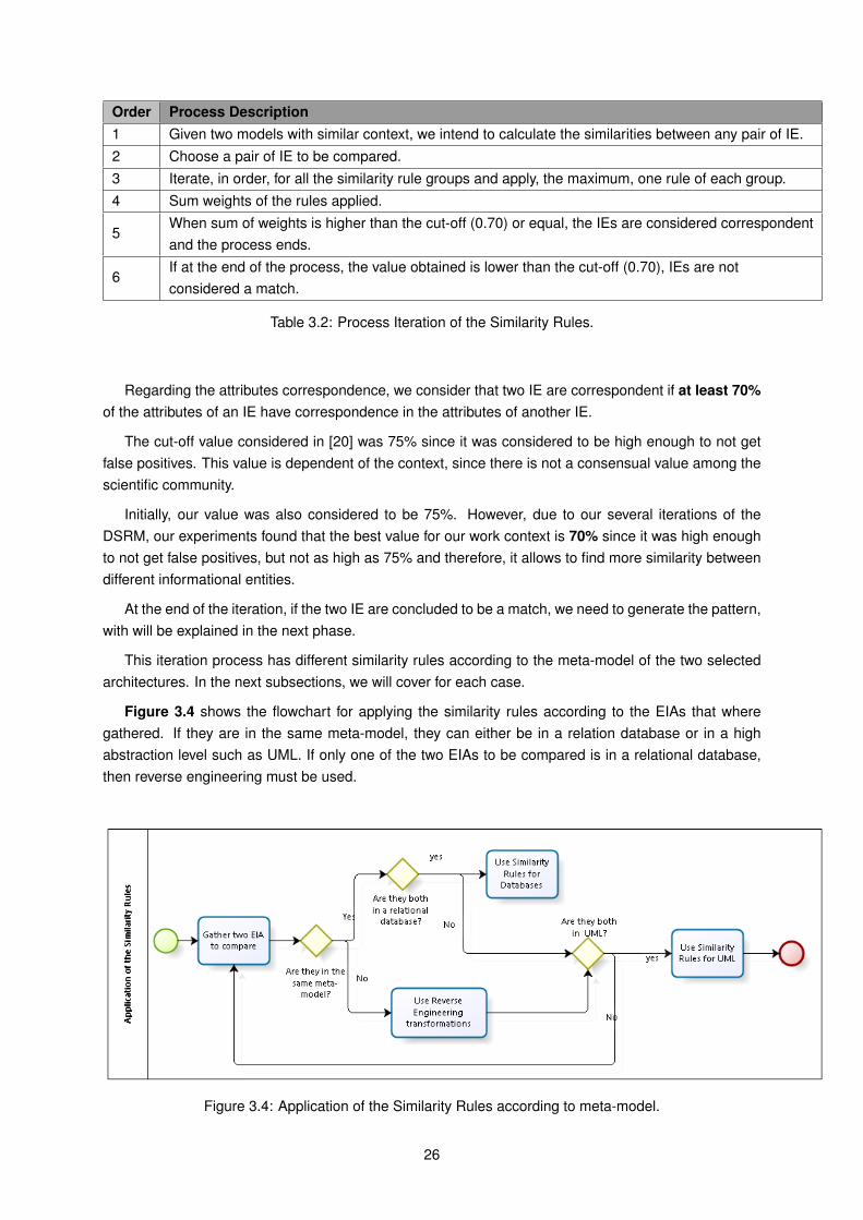
3.1 Conditions when selecting EIAs to be compared. . . . . . . . . . . . . . . . . . . . . . . . 233.2 Process Iteration of the Similarity Rules. . . . . . . . . . . . . . . . . . . . . . . . . . . . . 263.3 Similarity Rules for Relational Databases. . . . . . . . . . . . . . . . . . . . . . . . . . . . 273.4 Similarity Rules for EIA modeled in UML. . . . . . . . . . . . . . . . . . . . . . . . . . . . 283.5 Classification of Patterns and Anti-patterns . . . . . . . . . . . . . . . . . . . . . . . . . . 34
5.1 Analysis of the number of people needed to create each catalog. . . . . . . . . . . . . . . 505.2 Comparison of the catalogs according to quality factors of Moody & Shanks. . . . . . . . . 515.3 Differences between our work method and Brás’ method. . . . . . . . . . . . . . . . . . . 525.4 Comparison between our work method and Yesika’s. . . . . . . . . . . . . . . . . . . . . . 53
vii
List of Figures
1.1 The DSRM process. . . . . . . . . . . . . . . . . . . . . . . . . . . . . . . . . . . . . . . . 4
2.1 The Enterprise Architecture layers. . . . . . . . . . . . . . . . . . . . . . . . . . . . . . . . 72.2 A conceptual approach to EIA Reference Architecture. . . . . . . . . . . . . . . . . . . . . 102.3 Removal of tables exclusive do DBs . . . . . . . . . . . . . . . . . . . . . . . . . . . . . . 152.4 Removal of attributes exclusive to BDs. . . . . . . . . . . . . . . . . . . . . . . . . . . . . 162.5 Removal of Foreign Keys. . . . . . . . . . . . . . . . . . . . . . . . . . . . . . . . . . . . . 162.6 Removal of Tables which contain only exclusive Foreign Keys. . . . . . . . . . . . . . . . . 17
3.1 Process model of the solution proposal. . . . . . . . . . . . . . . . . . . . . . . . . . . . . 213.2 Solution Proposal steps. . . . . . . . . . . . . . . . . . . . . . . . . . . . . . . . . . . . . . 223.3 Flowchart of the process to calculate the name similarity between IEs. . . . . . . . . . . . 243.4 Application of the Similarity Rules according to meta-model. . . . . . . . . . . . . . . . . . 263.5 Reverse Engineering transformations. . . . . . . . . . . . . . . . . . . . . . . . . . . . . . 293.6 Rule 1 of the Pattern Generation. . . . . . . . . . . . . . . . . . . . . . . . . . . . . . . . . 303.7 Rule 2 of the Pattern Generation. . . . . . . . . . . . . . . . . . . . . . . . . . . . . . . . . 313.8 Rule 3 of the Pattern Generation. . . . . . . . . . . . . . . . . . . . . . . . . . . . . . . . . 313.9 Rule 4 of the Pattern Generation. . . . . . . . . . . . . . . . . . . . . . . . . . . . . . . . . 323.10 Rule 4 of the Pattern Generation. . . . . . . . . . . . . . . . . . . . . . . . . . . . . . . . . 333.11 Structure of the documented patterns. . . . . . . . . . . . . . . . . . . . . . . . . . . . . . 35
4.1 Database tables of Model A from the academic example. . . . . . . . . . . . . . . . . . . 384.2 Model B from academic example. . . . . . . . . . . . . . . . . . . . . . . . . . . . . . . . . 394.3 Model A after reverse engineering techniques, from academic example. . . . . . . . . . . 404.4 The resulting pattern from academic example. . . . . . . . . . . . . . . . . . . . . . . . . 414.5 Relational Database of AMA with tables that only have meaning in a DB model. . . . . . . 434.6 Relational Database of AMA with tables containing exclusively and only foreign keys. . . . 444.7 Relational Database of AMA with table with foreign keys. . . . . . . . . . . . . . . . . . . . 444.8 Relational Database of AMA with an example table named Group_. . . . . . . . . . . . . 454.9 IE Group_ from Portal do Cidadão modeled to UML. . . . . . . . . . . . . . . . . . . . . . 454.10 Balcão do Empreendedor translated to English, due to phase 1 conditions. . . . . . . . . 464.11 Example of an AMA’s generated pattern. . . . . . . . . . . . . . . . . . . . . . . . . . . . . 474.12 AMA example of a generated pattern documented in AMA’s EIA Pattern Catalog. . . . . . 48
5.1 Part of AMA’s Service Catalog. . . . . . . . . . . . . . . . . . . . . . . . . . . . . . . . . . 495.2 The data model quality factors by Mood & Shanks. . . . . . . . . . . . . . . . . . . . . . . 50
viii
Acronyms
AMA Agência para a Modernização Administrativa. 2, 3, 5, 36, 42
DB DataBase. 7, 15, 16, 28
DSRM Design Science Research Methodology. 3, 26
EA Enterprise Architecture. 6, 17
EIA Enterprise Information Architecture. 1–3, 5, 21, 25, 27, 35, 42
ER Entity-Relationship. 11
FK Foreign Key. 37
IA Information Architecture. 7
IDEF1X Integration DEFinition for information modeling. 12
IE Informational Entity. 8, 18, 19, 21, 23, 25, 31, 32
IS Information Systems. 2, 3
IT Information Technology. 9
PA Public Administration. 1–3, 21
PK Primary Key. 37
UML Unified Modeling Language. 11, 27
URI Uniform Resource Identifier. 24
ix

Chapter 1
Introduction
Enterprise Information Architecture (EIA) has become very important for business sustainability andcompetitive advantage today. According to Godinez et al. [1], firms of all dimensions search for prac-tical ways to create business value by using information and correlating insights to be able to predictoutcomes. This information era poses unique challenges, such as how to make information quick andeasily accessible to people and processes that need it, and at the same time, how to protect and securethat information and mitigate risks inherent in business decision making [1].
As enterprises become increasingly information based, making improvements in their informationactivities is a top priority to assure their continuing competitiveness. A key to achieve these improve-ments is developing an Enterprise Information Architecture. An EIA can be viewed as a structured setof multidimensional interrelated elements that support all information processes [2].
1.1 Motivation
Information and systems for its management are critical elements for the efficient and effective opera-tion of today’s knowledge dependent organizations [3]. From an organization’s perspective, informationmanagement ensures that valuable information is acquired and exploited to its fullest extent. Becauseof the critical dependency of organizations on information, improving its overall management can yieldsignificant operational benefits to all areas of an organization and importantly its overall efficiency, com-petitiveness and responsiveness [3].
Therefore, improving the management of information has been a real concern for organizations, andfor that reason, EIA in organizations is extremely important. Public Administration (PA) is no different,and, as a result, the development and improvement of an EIA as a reference for the PA has become afundamental goal.
The discovery and use of patterns for EIA can help enterprises meet their future needs, reduce in-compatibilities, missing elements and unnecessary duplication in information. A large number of papersand books published about patterns supports the view that the concept of the design pattern is val-ued by many experienced developers as a categorization of recurring issues (and solutions), as well asproviding a widely used vocabulary for discussing design [4].
The experience of experts enables them to find solutions for many recurring problems, creatingdesign patterns. Juniors can resolve problems as if they have many years of experience by reusingsolutions for similar problems [5]. Despite the importance of patterns, there is not a process that allowsits discovery, since the specification of patterns is realized by experts.
Defining patterns for any type of architecture in order to make use of the knowledge and experience
1
acquired by architects through their projects is necessary, since it can help reducing effort and time inthe development of architectures and can be a guide for future works with similar contexts [6].
There are many patterns and anti-patterns yet to be discovered, because standard existing patterns,such as client-server [7], don’t cover all existing architectures in EIA [8]. Even though each system isunique, there are many systems with similar areas with similar architectures, and as such, there’s aprobability that patterns can be discovered.
Also in the Portuguese Administration context we have faced the lack of specific methodologiesfor improving and updating the Enterprise Information Architecture, regarding future projects with sim-ilar context. As so, this thesis proposes a pattern-based approach for improving currently existing ap-proaches for EIA, with special attention to PA organizations, where we will make an EIA patterns catalogfor Government, to be used as the basis in future projects with akin context.
This work will be focused on the Portuguese Government organization, more specifically, Agênciapara a Modernização Administrativa (AMA), the agency responsible for the execution of the project ofthe information architecture for the Portuguese public administration.
1.2 Problem Statement
This section describes the “Identify Problem & Motivate” step of the DSRM Process Model and has theobjective to describe the research problem and to justify the value of a solution.
Information management systems that are not well aligned to the organization or the existing Infor-mation Systems (IS) infrastructure can have a significant detrimental effect on the organization and itsperformance [9].
Because of the critical dependency of organizations on information, improving its overall manage-ment can yield significant operational benefits to all areas of an organization as well as its overall effi-ciency, competitiveness and responsiveness [10].
Saiz et al. [11] confirm that in the literature, there are some frameworks that deal with performancemanagement/measurement for inter-organizational contexts, and that each framework deals in detailcertain aspects of performance measurement and present a specific structure. However, the authorssay that practically all of these frameworks present a common gap: the low degree of consideration ofinformation treatment (acquisition, analysis, storage). As such, they recognize the importance of de-veloping information architectures, methodologies and systems to facilitate performance management’ssuccess in the long term [11].
Ernst, in [12], states that methods for EA management (which includes EIA) are documented on atoo generic level to solve problems occurring in the EA management context. He also states that existingmethods are often too company-specific and can therefore not be used as a general solution to existingproblems. He affirms that a few engineering oriented approaches to EA management are currently indevelopment, but none of them can be considered to be widely accepted in the EA community. Typicalframeworks for managing the EA also only partially contribute to the solution of the aforementionedproblems as they may be helpful for an architect in his daily work, but knowing them does not make onean architect, because experience and knowledge is required to apply a framework.
In the Portuguese Public Admnistration context, as declared by EORG@AP Group and by Gomes[13], one of the main concerns that need to be regulated at the Public Administration’s Enterprise Ar-chitecture is the accessibility, reliability, ontology and security of the information entities. Furthermore,information entities are part of the independent components in the Enterprise Architecture and theyrepresent all the human resources, material and immaterial involved in the activities performed.
Fowler [14] stated that "Frequently I find that many aspects of a project revisit problems I have faced
2
before". Good architecture is a critical factor in the success of the system development. As mentionedin the previous chapters, a prominent approach to document knowledge in software engineering arepatterns, which originally were introduced in architecture where patterns are used to document recurringsolutions to common problems in a given context [12].
Regarding the development of the IS in some sectors of the PA, the non-conformity with a certain setof norms and requirements can lead to the lack of interoperability between those systems [15], and theincrease in the difficulties in its maintenance [16].
Therefore, the importance of information in the Portuguese PA, the lack of specific methodologies forimproving and developing the Enterprise Information Architectures and the nonexistence of a methodto create an EIA patterns catalog in the Portuguese Public Administration regarding future projects withsimilar context, lead us to need for the Portuguese Public Administration to have a catalog of EIA patternsto be used as the basis for future projects that have akin context with former PA projects.
The questions that this research will address are:
• Is it possible to create a catalog of Information Architectures patterns to be used by the PortuguesePA, specifically AMA ?
• How do we compare different Enterprise Information Architectures?
• How can we extract patterns and anti-patterns?
• How do we document Enterprise Information Architecture patterns and anti-patterns?
1.3 Contributions
Based on the problem questions described above, this thesis contributes to the development of bothEnterprise Information Architecture and pattern themes, especially among the Portuguese Public Ad-ministration. As such, we aim such contributions by:
• Stressing the importance of using patterns in Enterprise Information Architecture;
• Defining the conditions for generating Enterprise Information Architecture patterns;
• Proposing a method to compare different Enterprise Information Architectures, based ondifferent methodologies;
• Propose a method to extract Enterprise Information Architectures patterns;
• Define how to document those patterns;
• Creation of an EIA patterns catalog to be used by AMA.
In addition, to disseminate this work, the paper [17] was accepted and presented at 8o INForum 1.
1.4 Research Method
The methodology applied is Design Science Research Methodology (DSRM), where a proposal is de-veloped and validated to solve our problem [18]. It is a system of principles, practices and proceduresneeded to execute a study. Its objective is to overcome research paradigms, for instance the traditional
1http://inforum.org.pt/INForum2016
3
descriptive and interpretative research, in which the outputs are mostly explanatory and, one coulddispute, are often not applicable in practice [19].
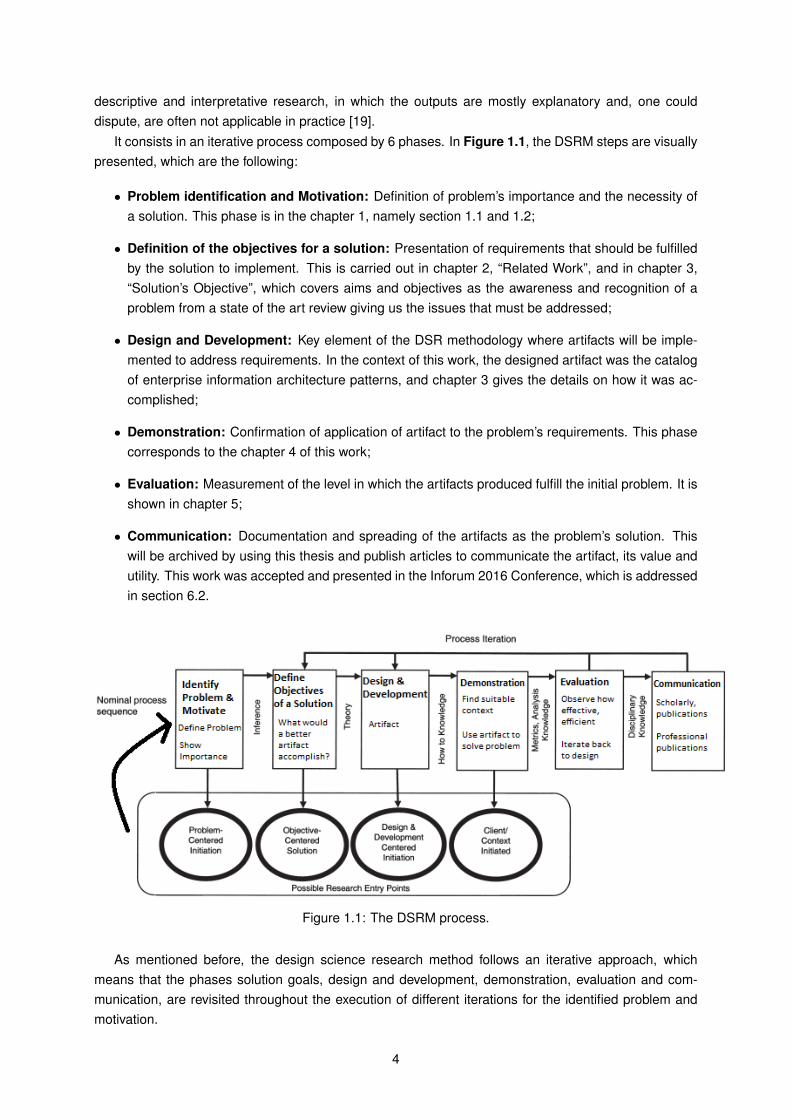
It consists in an iterative process composed by 6 phases. In Figure 1.1, the DSRM steps are visuallypresented, which are the following:
• Problem identification and Motivation: Definition of problem’s importance and the necessity ofa solution. This phase is in the chapter 1, namely section 1.1 and 1.2;
• Definition of the objectives for a solution: Presentation of requirements that should be fulfilledby the solution to implement. This is carried out in chapter 2, “Related Work”, and in chapter 3,“Solution’s Objective”, which covers aims and objectives as the awareness and recognition of aproblem from a state of the art review giving us the issues that must be addressed;
• Design and Development: Key element of the DSR methodology where artifacts will be imple-mented to address requirements. In the context of this work, the designed artifact was the catalogof enterprise information architecture patterns, and chapter 3 gives the details on how it was ac-complished;
• Demonstration: Confirmation of application of artifact to the problem’s requirements. This phasecorresponds to the chapter 4 of this work;
• Evaluation: Measurement of the level in which the artifacts produced fulfill the initial problem. It isshown in chapter 5;
• Communication: Documentation and spreading of the artifacts as the problem’s solution. Thiswill be archived by using this thesis and publish articles to communicate the artifact, its value andutility. This work was accepted and presented in the Inforum 2016 Conference, which is addressedin section 6.2.
Figure 1.1: The DSRM process.
As mentioned before, the design science research method follows an iterative approach, whichmeans that the phases solution goals, design and development, demonstration, evaluation and com-munication, are revisited throughout the execution of different iterations for the identified problem andmotivation.
4
It finishes when the answer to the stated problem is achieved, having as evidence the outcome ofthe results of applying the proposed solution.
If there is no positive answer to the stated problem, goals of the solution should be revised and adifferent approach should be addressed.
The starting point was the evaluation of a previous work by Brás [20]. For the problem stated insection 1.2, various iterative actions where overseen. On the first iteration, a evaluation of a previouswork by Brás [20] was carried out, since part of his work was going to be used for this thesis. During thenext iterations, some improvements were being made, such as the need to add a new similarity rule forcomparing different EIAs after initially established in the design and development phase of the DSRM.There were also some modifications on the pattern generation rules. A basic condition was also addedin our solution proposal after an evaluation phase of an DSRM iteration. Due to the several iterationsand experiments, we were also able to choose the best value for the cut-off in the matching process ofour solution proposal.
1.5 Document Structure
This dissertation is composed by six chapters. To be coherent with our research work, this disserta-tion will follow the same structure as DSRM which phases are easily mapped to the structure of thisdocument.
First, in chapter 1, the motivation, problem statement, contributions and research method are pre-sented.
In chapter 2, the related work is detailed, namely Information architecture, Enterprise InformationArchitecture, the definition of patterns and its documentation, among other related works.
The Problem Statement section and the Related Work chapter identify the problem and the motivationbehind the research work.
In chapter 3, the solution hypothesis and proposal are presented, where the objectives of the solutionare detailed as well as the proposed solution.
In chapter 4, we demonstrate the application of our artifact with an academic example and also witha sample of AMA’s EIA, namely the comparison between Portal do Cidadão with Balcão do Empreende-dor.
In chapter 5, we show the evaluation and analysis results.Finally in chapter 6, some conclusions are presented, some lessons learned are detailed and sug-
gestions for future work are given.The communication step of the DSRM is addressed in section 6.2.
5
Chapter 2
Related Work
In this chapter, it is presented a literature review of the topics related and most relevant to this work.This chapter starts by introducing the concepts of the different types of architectures, followed by
the definition of a graphical notation for representing software systems - and the information entities byInmon. Later on, it’ll be introduced the concept of patterns and methods to document them. The workdeveloped by AMA will be described as well as other related works concerning this thesis’ theme.
2.1 Enterprise Architecture
Aier [21] states that the basic idea about Enterprise Architecture (EA) is to map the most importantartifacts of an enterprise together with their relationships to a model. The modeling seeks to describethe reciprocal dependencies of the subjects of organization of an enterprise on an aggregated level.This is done for documentation and for analysis reasons, but also to plan the future development [12].
Ersnt [12] noted that there are various definitions of EA which lead to the problem that there is nogeneral accepted definition of the term, ending up in confusion in discussions about this topic. Hepursued a similar approach like TOGAF and resorts to ISO/IEC 42010 standard as a basis for thedefinition of EA which is the following: “the enterprise architecture is the fundamental conception ofthe enterprise in its environment embodied in its elements, their relationships to each other and to itsenvironment, and the principles guiding its design and evolution” [12].
The Zachman Framework says that an organization doesn’t have just one architecture, but a setof them, arranged as layers. Each of these layers produce artifacts that answer six organizationalquestions (what, where, when, why, who and how) [22]. The alignment between business and IT andthe coordinated steering based on information about the EA are the most important aspects of EAmanagement.
The complexity of the Enterprise Architecture can be represented based on a collection of architec-tural layers: each layer supports the needs of the one above it, with the top one precisely supporting thecapabilities required by the business strategy [1]. These layers are shown in Figure 2.1.
The layers mentioned above are the described in more detail as it follows [1]:
• Enterprise Strategy Layer: this layer mainly describes an enterprise strategy regarding productportfolio and appropriate customer segments, appropriate delivery and distribution channels in thegiven market environment, competitors and core competencies, and capabilities of the company;
• Business Layer: in order to develop an Enterprise Architecture, it is necessary to provide theprocess and integrated tools to identify the as-is state of the organization (the business and IT
6
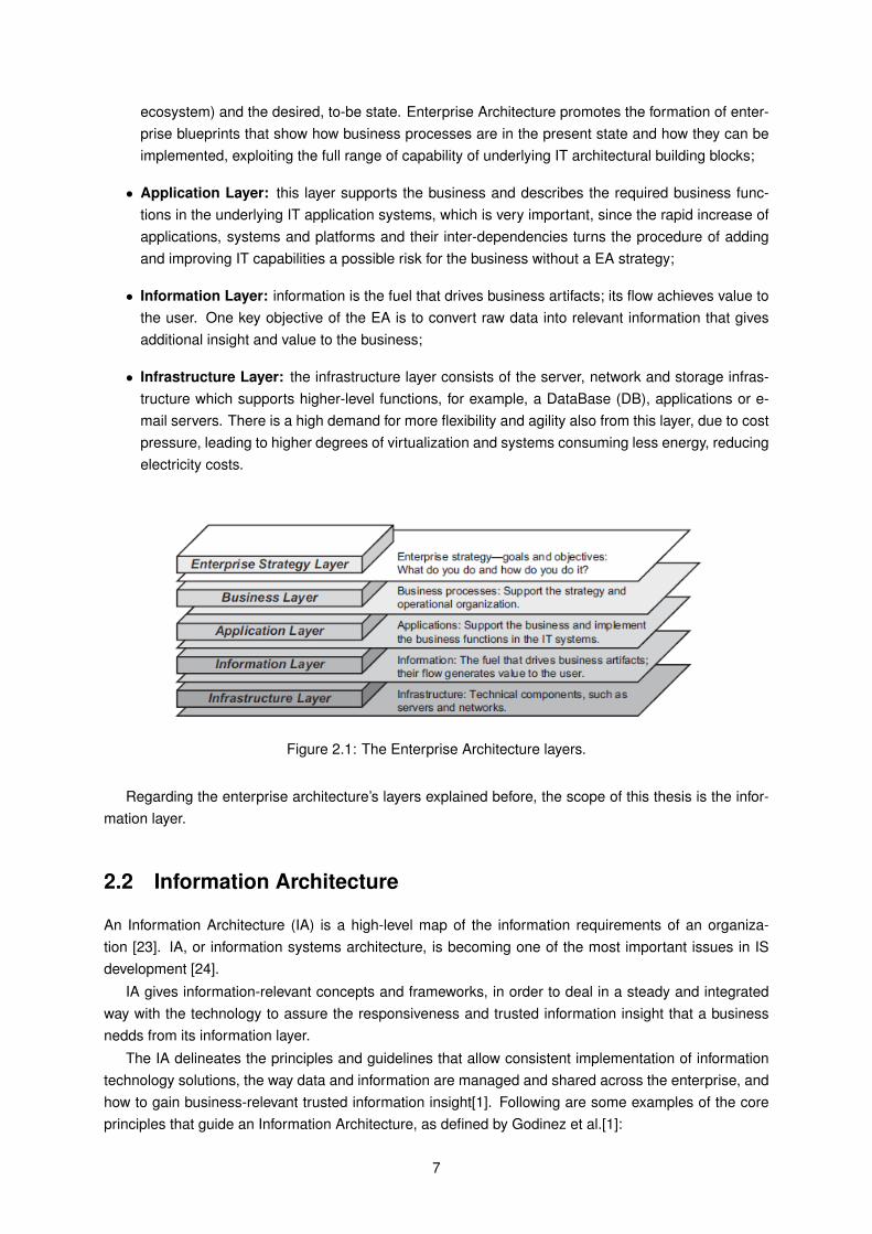
ecosystem) and the desired, to-be state. Enterprise Architecture promotes the formation of enter-prise blueprints that show how business processes are in the present state and how they can beimplemented, exploiting the full range of capability of underlying IT architectural building blocks;
• Application Layer: this layer supports the business and describes the required business func-tions in the underlying IT application systems, which is very important, since the rapid increase ofapplications, systems and platforms and their inter-dependencies turns the procedure of addingand improving IT capabilities a possible risk for the business without a EA strategy;
• Information Layer: information is the fuel that drives business artifacts; its flow achieves value tothe user. One key objective of the EA is to convert raw data into relevant information that givesadditional insight and value to the business;
• Infrastructure Layer: the infrastructure layer consists of the server, network and storage infras-tructure which supports higher-level functions, for example, a DataBase (DB), applications or e-mail servers. There is a high demand for more flexibility and agility also from this layer, due to costpressure, leading to higher degrees of virtualization and systems consuming less energy, reducingelectricity costs.
Figure 2.1: The Enterprise Architecture layers.
Regarding the enterprise architecture’s layers explained before, the scope of this thesis is the infor-mation layer.
2.2 Information Architecture
An Information Architecture (IA) is a high-level map of the information requirements of an organiza-tion [23]. IA, or information systems architecture, is becoming one of the most important issues in ISdevelopment [24].
IA gives information-relevant concepts and frameworks, in order to deal in a steady and integratedway with the technology to assure the responsiveness and trusted information insight that a businessnedds from its information layer.
The IA delineates the principles and guidelines that allow consistent implementation of informationtechnology solutions, the way data and information are managed and shared across the enterprise, andhow to gain business-relevant trusted information insight[1]. Following are some examples of the coreprinciples that guide an Information Architecture, as defined by Godinez et al.[1]:
7
• Access and exchange of information: information services should give unconstrained accessto the appropriate users at the right time;
• Service re-use: promote the discovery, selection and re-usability of services and reassure theuse of uniform interfaces when possible;
• Information Governance: proper information technology should support the execution of an In-formation Governance strategy in an efficient way;
• Standards: a group of coherent standards for data and technology should be defined to facilitatesimplification across the Information Infrastructure.
When a Information Architecture is well designed and implemented, the consistent use of informationby all significant services and business applications is facilitated, as well as the access and transactionof information with services. The discovery and reuse of services is also promoted. For all the rea-sons mentioned above, a IA can deliver a stable, responsive, and consistent information-centric systembehavior [24].
Regarding the composition of an IA, it’s possible to distinguish three fundamental concepts[25]:
• Informational Entity (IE): any concept that has a meaning in the business context and in which ispossible and relevant to store information.
This concept can be, for example, a person, a place or anything physical and is usually character-ized by having a name, an unique identifier, a description and its structural relationship with otherinformational entities (and the derived relations with processes and applications);
• Attribute: any characteristic that defines an informational entity;
• Relationship: any pair of attributes related between themselves that add detail in the businesscontext.
To conclude, we can say that an IA is composed by informational entities, characterized by its at-tributes and by the relationships that the different informational entities establish between themselves.
Another concept of Information Architecture is the Inmon taxonomy, introduced by W. Inmon, which isa methodology to classify data. According to [26], data can be classified according to three dimensions:primitive vs. derived; historic vs. projected; publics vs. private. As so, there’s the following data types:
• Primitive Data: are specified with a single fact;
• Derived Data: calculated data aggregated or summarized; based on one or more primitive dataor other data derived from;
• Historical Data: record unambiguous and irrefutable facts; the values recorded are accurate andthere is agreement about the means to obtain or calculate them;
• Projected Data: are estimates, predictions or inferences from facts that might happen and theremay not be unanimity about the means to obtain or calculate;
• Public Data: data that have multiple stakeholders and may be visible outside the organization. Itsintegrity is maintained by the organization;
• Private Data: are owned by a single individual or group of individuals. They reflect specific needsand may not be relevant or not to make sense out of a limited context. Its integrity is managedlocally.
8
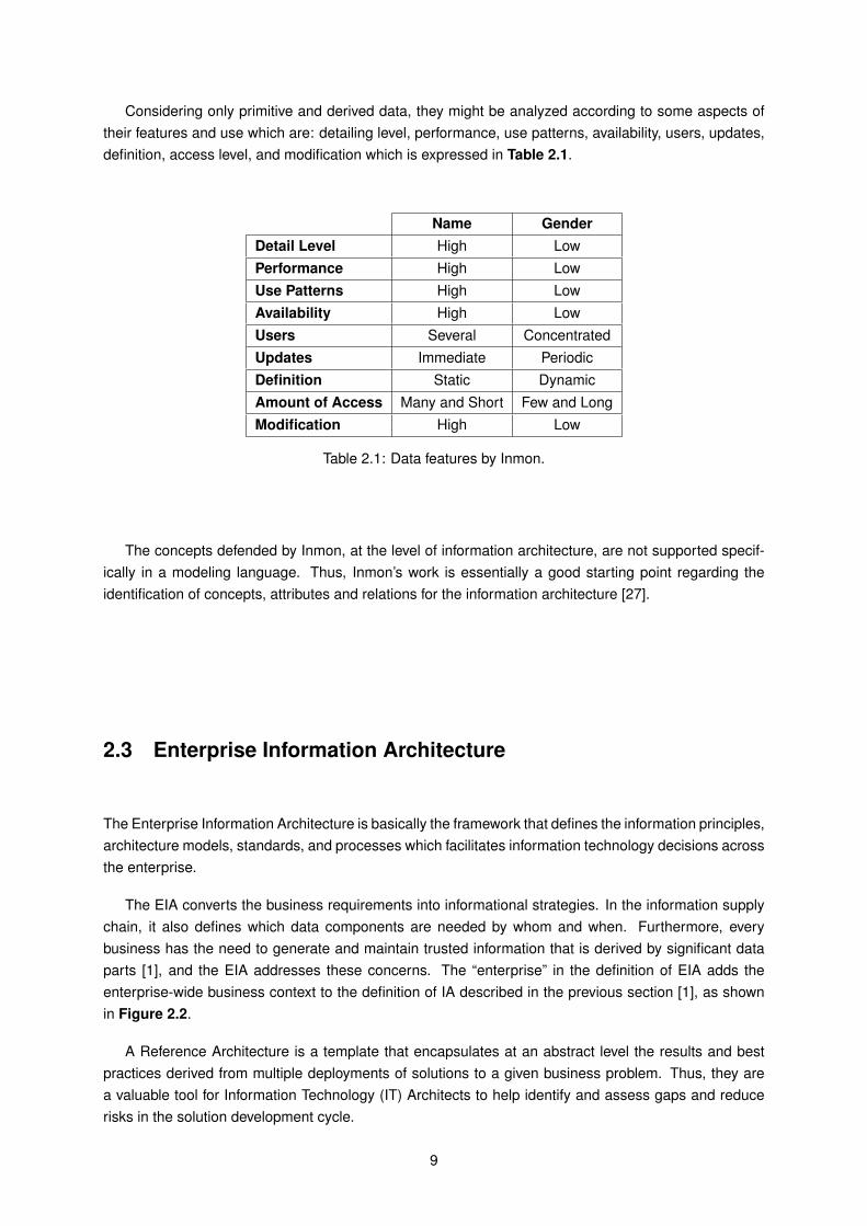
Considering only primitive and derived data, they might be analyzed according to some aspects oftheir features and use which are: detailing level, performance, use patterns, availability, users, updates,definition, access level, and modification which is expressed in Table 2.1.
Name GenderDetail Level High LowPerformance High LowUse Patterns High LowAvailability High LowUsers Several ConcentratedUpdates Immediate PeriodicDefinition Static DynamicAmount of Access Many and Short Few and LongModification High Low
Table 2.1: Data features by Inmon.
The concepts defended by Inmon, at the level of information architecture, are not supported specif-ically in a modeling language. Thus, Inmon’s work is essentially a good starting point regarding theidentification of concepts, attributes and relations for the information architecture [27].
2.3 Enterprise Information Architecture
The Enterprise Information Architecture is basically the framework that defines the information principles,architecture models, standards, and processes which facilitates information technology decisions acrossthe enterprise.
The EIA converts the business requirements into informational strategies. In the information supplychain, it also defines which data components are needed by whom and when. Furthermore, everybusiness has the need to generate and maintain trusted information that is derived by significant dataparts [1], and the EIA addresses these concerns. The “enterprise” in the definition of EIA adds theenterprise-wide business context to the definition of IA described in the previous section [1], as shownin Figure 2.2.
A Reference Architecture is a template that encapsulates at an abstract level the results and bestpractices derived from multiple deployments of solutions to a given business problem. Thus, they area valuable tool for Information Technology (IT) Architects to help identify and assess gaps and reducerisks in the solution development cycle.
9
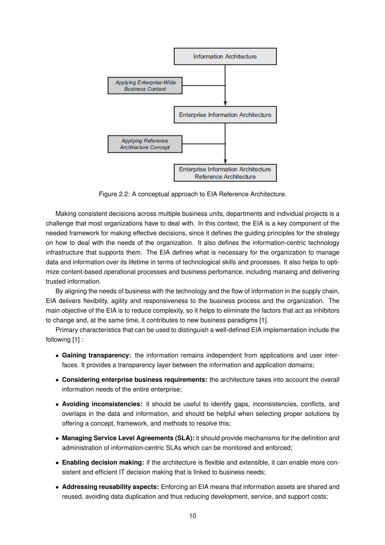
Figure 2.2: A conceptual approach to EIA Reference Architecture.
Making consistent decisions across multiple business units, departments and individual projects is achallenge that most organizations have to deal with. In this context, the EIA is a key component of theneeded framework for making effective decisions, since it defines the guiding principles for the strategyon how to deal with the needs of the organization. It also defines the information-centric technologyinfrastructure that supports them. The EIA defines what is necessary for the organization to managedata and information over its lifetime in terms of technological skills and processes. It also helps to opti-mize content-based operational processes and business perfomance, including manaing and deliveringtrusted information.
By aligning the needs of business with the technology and the flow of information in the supply chain,EIA delivers flexibility, agility and responsiveness to the business process and the organization. Themain objective of the EIA is to reduce complexity, so it helps to eliminate the factors that act as inhibitorsto change and, at the same time, it contributes to new business paradigms [1].
Primary characteristics that can be used to distinguish a well-defined EIA implementation include thefollowing [1] :
• Gaining transparency: the information remains independent from applications and user inter-faces. It provides a transparency layer between the information and application domains;
• Considering enterprise business requirements: the architecture takes into account the overallinformation needs of the entire enterprise;
• Avoiding inconsistencies: it should be useful to identify gaps, inconsistencies, conflicts, andoverlaps in the data and information, and should be helpful when selecting proper solutions byoffering a concept, framework, and methods to resolve this;
• Managing Service Level Agreements (SLA): it should provide mechanisms for the definition andadministration of information-centric SLAs which can be monitored and enforced;
• Enabling decision making: if the architecture is flexible and extensible, it can enable more con-sistent and efficient IT decision making that is linked to business needs;
• Addressing reusability aspects: Enforcing an EIA means that information assets are shared andreused, avoiding data duplication and thus reducing development, service, and support costs;
10
• Addressing data scope: The Information Reference Model (see Chapter 3) used by the enter-prise describes the scope of the used data and information supported by the EIA;
• Defining a technology strategy: It establishes the framework upon which the technology strate-gies adopted by the enterprise depend. In addition, it defines the set of principles that guide howan organization’s information systems and technology infrastructure are engineered.
2.4 Data Modeling
We address two different approaches for data modeling: Entity-Relationship (ER) modeling and UMLmodeling. Those are the ones that are mostly used among industry, and we found them as the ones thatshould be studied in order to help us developing our work. Data modeling using UML is addressed first,followed by a resume of Entity-relationship modeling.
2.4.1 UML
The Unified Modeling Language (UML), is an open standard controlled by the Object ManagementGroup (OMG) which is a family of graphical notations, defined over a single meta-model. It is useful inthe design and description of software systems, especially those which use an object-oriented approach[28].
To date, UML is mainly used in industry for designing object-oriented program code. Although it canbe used for designing databases, it had little success in displacing other approaches such as ER for thispurpose [29]. However, Halpin [29] states that UML is a very important language that could well becomepopular for database design in the future. As such, we address UML notation in the data-modelingcontext, especially because of the background information regarding our problem and solution.
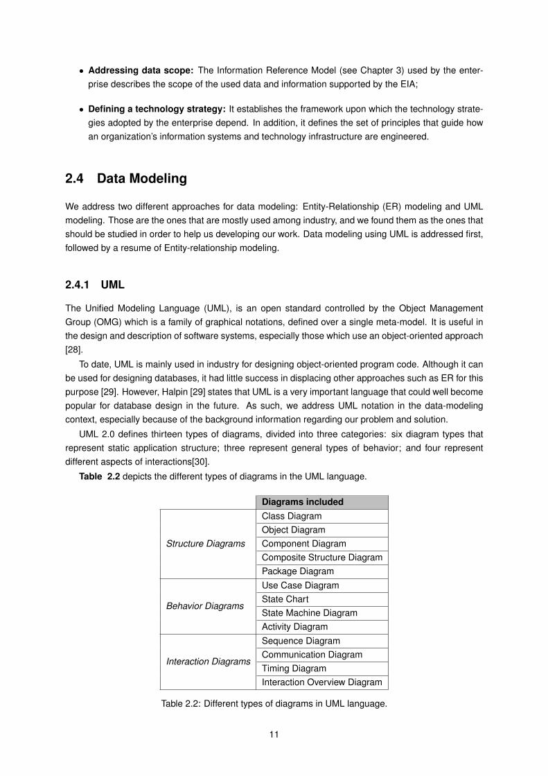
UML 2.0 defines thirteen types of diagrams, divided into three categories: six diagram types thatrepresent static application structure; three represent general types of behavior; and four representdifferent aspects of interactions[30].
Table 2.2 depicts the different types of diagrams in the UML language.
Diagrams includedClass DiagramObject DiagramComponent DiagramComposite Structure Diagram
Structure Diagrams
Package DiagramUse Case DiagramState ChartState Machine Diagram
Behavior Diagrams
Activity DiagramSequence DiagramCommunication DiagramTiming Diagram
Interaction Diagrams
Interaction Overview Diagram
Table 2.2: Different types of diagrams in UML language.
11
The one which is used in this thesis is the class diagram represents the static view of an applicationand describes the attributes and operations of a class and also the constraints imposed on the system.The class diagram is the only UML diagram that can be mapped directly with object oriented languagesand therefore, it is widely used in the modeling of object oriented systems [28].
Furthermore, the class diagram shows a collection of classes, interfaces, associations, collaborationsamong the elements of the static view and constraints, while describing the functions performed by thesystem.
2.4.2 Entity-Relationship Modeling
The ER approach was originally introduced by Chen, in 1976 [31]. Its original notation uses rectanglesfor entity types and diamonds for relationships. Attributes may be defined, but are excluded from the ERdiagram.
Although the ER diagrams do not display attributes, relationships may have attributes, but they can’tplay roles in other relationships, according to [29]. Relationships are formalized in terms of orderedtuples of entities, allowing the order to be dropped if role names are used [31].
Citing [29], one problem with the ER approach is that there is an abounding number of versions ofthe ER modeling, with no single standard. Nonetheless, in industry, the most popular versions of pureER are the Barker and Information Engineering notations[32]. Another popular notation is IntegrationDEFinition for information modeling (IDEF1X) [33], which is a hybrid of ER and relational notation.
2.4.3 Comparison between ER Model and UML
With the two data modeling approaches described, we are going to analyze them taking in considerationboth their key features and this work’s context. As such, we focused this comparative analysis in thefollowing vectors, based on [13]:
• Entities representation: defines how well an entity is represented in the modeling language;
• Attributes representation: how well the relationships are depicted in the modeling language;
• Relationships representation: how well the relationships are depicted in the modeling language;
• Alignment with enterprise context: aims to frame the modeling language in this work’s context,especially the Enterprise Information Architecture context. This vector raises with the restrictionsof the EIA patterns that we aim in our research.
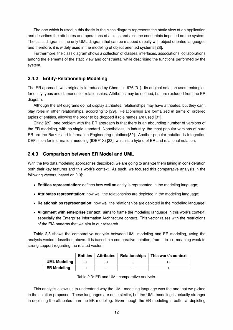
Table 2.3 shows the comparative analysis between UML modeling and ER modeling, using theanalysis vectors described above. It is based in a comparative notation, from – to ++, meaning weak tostrong support regarding the related vector.
Entities Attributes Relationships This work’s contextUML Modeling ++ ++ + ++ER Modeling ++ + ++ +
Table 2.3: ER and UML comparative analysis.
This analysis allows us to understand why the UML modeling language was the one that we pickedin the solution proposed. These languages are quite similar, but the UML modeling is actually strongerin depicting the attributes than the ER modeling. Even though the ER modeling is better at depicting
12
the relationships between entities, it lacks when considering our context, since the work at presentdeveloped in the IA area in the Portuguese Public Administration already uses UML modeling as basis.
2.5 Pattern
Pattern is a concept well-known and used in various disciplines. One of these disciplines is architec-ture, which also established one of the earliest definitions for patterns. Patterns evolved from severalinitiatives. Kent Beck and Ward Cunning-ham, two of the pioneers of Smalltalk, came across the ideasof Christopher Alexander, who had developed a theory and collection of patterns in architecture [14].Alexander developed a range of theories about patterns in architecture and published these in a seriesof books [34].
Alexander et al. [34] declared that “each pattern describes a problem which occurs over and overagain in our environment, and then describes the core of the solution to that problem, in such a way thatyou can use this solution a million times over, without ever doing it the same way twice. Each pattern isa three-part rule, which expresses a relation between a certain context, a problem and a solution”.
Fowler [14] stated that as a result of the diversity of patterns community, he had difficulty in definingthe term pattern. He further affirms that we all think we can recognize a pattern when we see it, we thinkmost of us would agree in most cases, but we cannot come up with a single definition. He concludedthat “a pattern is an idea that has been useful in one practical context and will probably be useful inothers”.
The fourth volume of the Pattern-Oriented Software Architecture series [35] defines a pattern asfollows: “a pattern describes a particular recurring design problem that arises in specific design contextsand presents a well-proven solution for the problem. The solution is specified by describing the roles of itsconstituent participants, their responsibilities and relationships, and the ways in which they collaborate”.
Douglass explained in his book [36] that over the years, experienced developers have encounteredthe same problems over and over, and even if they are not exactly the same problems, they have verythings in common. He believes that the very best developers abstract these problems and their solutionsinto generalized approaches (patterns) that have proved consistently effective.
Patterns have become accepted in many different areas and described as very useful because theyreuse knowledge already acquired from experienced users and they capture and document provenpractices [12].
Anti-pattern is also a concept worth mentioning. It describes a commonly occurring solution to aproblem that generates decidedly negative consequences [37]. The anti-pattern may be the result ofa manager or a developer not having sufficient knowledge or experience in solving a particular type ofproblem, or having applied a perfectly good pattern in the wrong context.
2.5.1 Documentation of Patterns
One of the most popular pattern forms is the Alexandrian Form [34], which consists of:
• Name: Should be memorable, usable and distict;
• Prologue: One sentence per pattern that can be expected to precede this pattern;
• Epilogue: One sentence per pattern that can be expected to follow this pattern;
• Problem statement: One or two sentences that summarize the problem solved by the pattern;
• Solution: One or two sentences that tell what to do to solve the problem;
13
• Diagram: A picture or two, hand sketched or photographed, that illustrate the pattern (and some-times the lack of the pattern);
• Discussion: Anywhere from 4 to 40 paragraphs that illuminate the system of forces resolved bythe pattern.
One of the criticisms for this method of documenting patterns is that it breaks the flow of the patternand makes you worry too much about whether issues should be discussed in the problem half or thesolution half.
Another pattern form mentioned in several books is the Portland form [12], which consists of thefollowing parts:
• Name;
• Context: The context and a brief description of the problem;
• Problem: Cause of the problem followed by the forces that must be resolved in order, roughly,from strongest to weakest and with conflicts between the forces highlighted;
• Solution: Describe a solution that resolves the strongest forces in this context;
• Resulting context: What has been resolved and what needs to be addressed next? What newpossibilities are available at this point and what new problems have arisen? What possibilities areno longer available, among others;
• Summary: Discussion about the greater context in which this pattern belongs, related patterns,and the specific relationships between those patterns and this one.
Buschmann et al. [35] concluded that there is no ideal pattern form and creating a new pattern orselecting an existing one should always have in consideration the experience of the author, the intentthat the pattern author has in mind when documenting a pattern, and the target audience.
2.6 Work developed by AMA
This work is developed in collaboration with Agência para a Modernização Administrativa (AMA), theagency responsible for the execution of the project of the information architecture for the Portuguesepublic administration. In order to be able to develop the intended catalog with enterprise informationarchitecture patterns, a initial phase of the solution’s architecture will consist on the analysis of twospecific contexts of the Portuguese public administration modernization, and it’s important to describethem as it constitutes the state of the art in the subject in Portugal and will provide us a initial basis towork on.
Being this work developed in collaboration with AMA, we will have access to the projects currentlyunder its orientation, like the Citizen Portal and the Entrepreneur Counter, that already integrate a fair setof information regarding the citizen and the entrepreneur. We will also have access to AMA’s InformationArchitecture.
A brief description of two of the projects of AMA that we will have access to and which will be usedto compare Enterprise Information Architectures is as it follows:
• Citizen Portal (Portal do Cidadão, in Portuguese): Its main goal is to simplify the relationshipbetween the citizens and the public organisms, being a privileged channel to the services providedby the public administration, where the citizens can also consult information online. Its data is in aMySQL and SQL database;
14
• Entrepreneur Counter (Balcão do Empreendedor, in Portuguese): It’s the point of access to theservices related to business activity, where the entrepreneurs can have access to various typesof contents, like how to create a company, register a trademark, get certificates or how to obtainactivities licensing. Its data is viewed in documents who use the UML standard.
• AMA’s Information Architecture: the document containing the model of AMA’s entities, its rela-tionships and specializations. It’s in a high abstraction level of representation 1.
2.7 Reverse Engineering
An abstraction for a software artifact is a succinct description that suppresses the details that are unim-portant to software developer and emphasizes the information that is important. According to [38],reverse engineering is the process of analyzing a subject system to identify the system’s componentsand their interrelationships and create representations of the system in another form or at a higher levelof abstraction.
Reverse engineering in and of itself does not involve changing the subject system or creating a newsystem. It is a process of examination, not a process of change or replication. Reverse engineering isuseful to abstract models of DBs in order to create representations of those models in a higher abstrac-tion level [20].
In this thesis, the set of transformations in reverse engineering will be used in the solution proposal(section 3.1). Those transformations are the following, adapted from [39] and [20]:
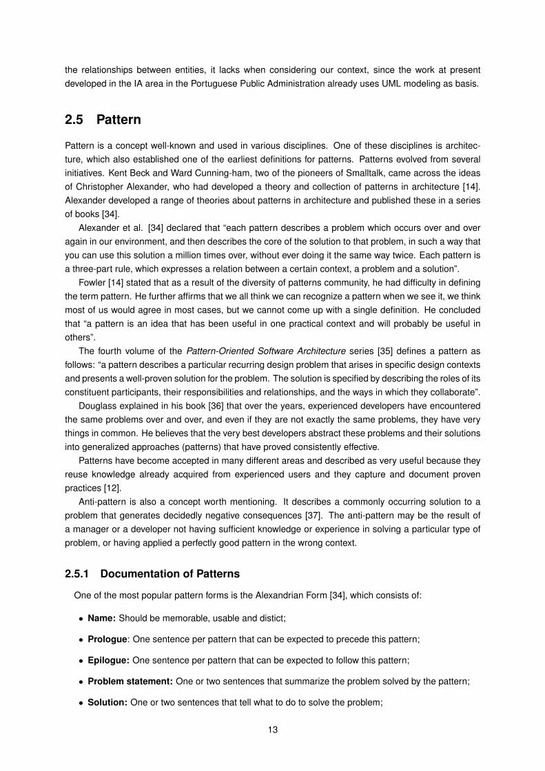
2.7.1 Removal of tables exclusive to DBs
Tables that only have a meaning and utility at the DB level must be removed in a higher abstraction level.Figure 2.3 depicts that table Act_HI_ACTINST has initially three attributes, proc_def_ID, proc_inst_ID
and call_proc_inst_ID, that only have utility at the DB representation level. Thus, in the final result, thistable is removed.
Figure 2.3: Removal of tables exclusive do DBs
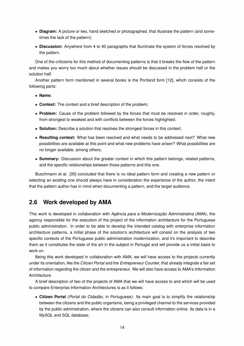
2.7.2 Removal of attributes exclusive to DBs
Attributes that only have a meaning and utility at the DB level must be removed in a higher abstractionlevel. Figure 2.4 shows that table T has initially two attributes, db_createdBy and db_lastUpdatedBy,that only have utility at the DB level. As such, in the final result, these two attributes are removed.
1https://m6.ama.pt/docs/ArquiteturaInformacional.pdf
15
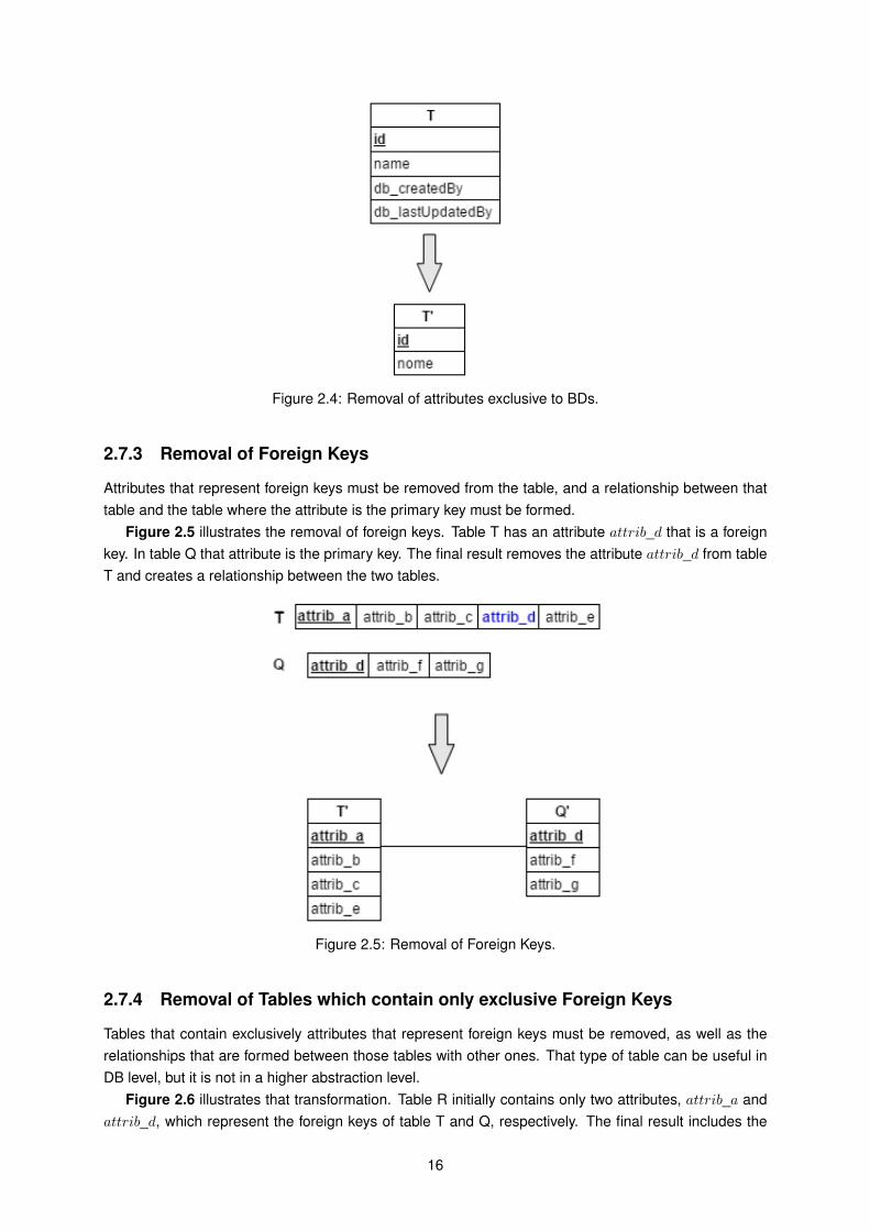
Figure 2.4: Removal of attributes exclusive to BDs.
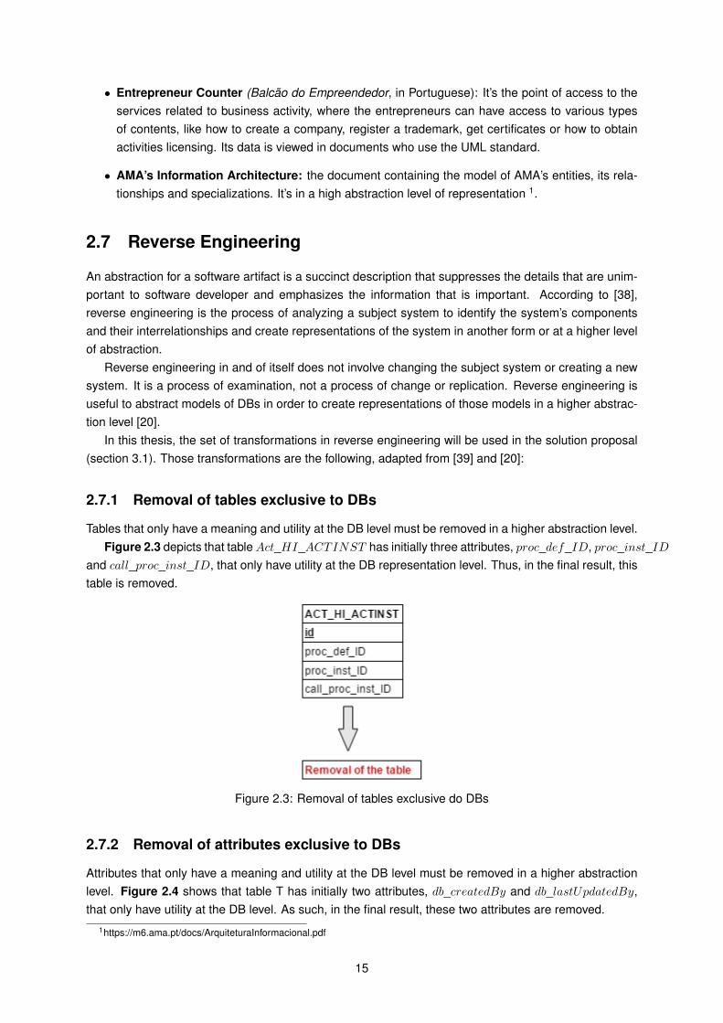
2.7.3 Removal of Foreign Keys
Attributes that represent foreign keys must be removed from the table, and a relationship between thattable and the table where the attribute is the primary key must be formed.
Figure 2.5 illustrates the removal of foreign keys. Table T has an attribute attrib_d that is a foreignkey. In table Q that attribute is the primary key. The final result removes the attribute attrib_d from tableT and creates a relationship between the two tables.
Figure 2.5: Removal of Foreign Keys.
2.7.4 Removal of Tables which contain only exclusive Foreign Keys
Tables that contain exclusively attributes that represent foreign keys must be removed, as well as therelationships that are formed between those tables with other ones. That type of table can be useful inDB level, but it is not in a higher abstraction level.
Figure 2.6 illustrates that transformation. Table R initially contains only two attributes, attrib_a andattrib_d, which represent the foreign keys of table T and Q, respectively. The final result includes the
16
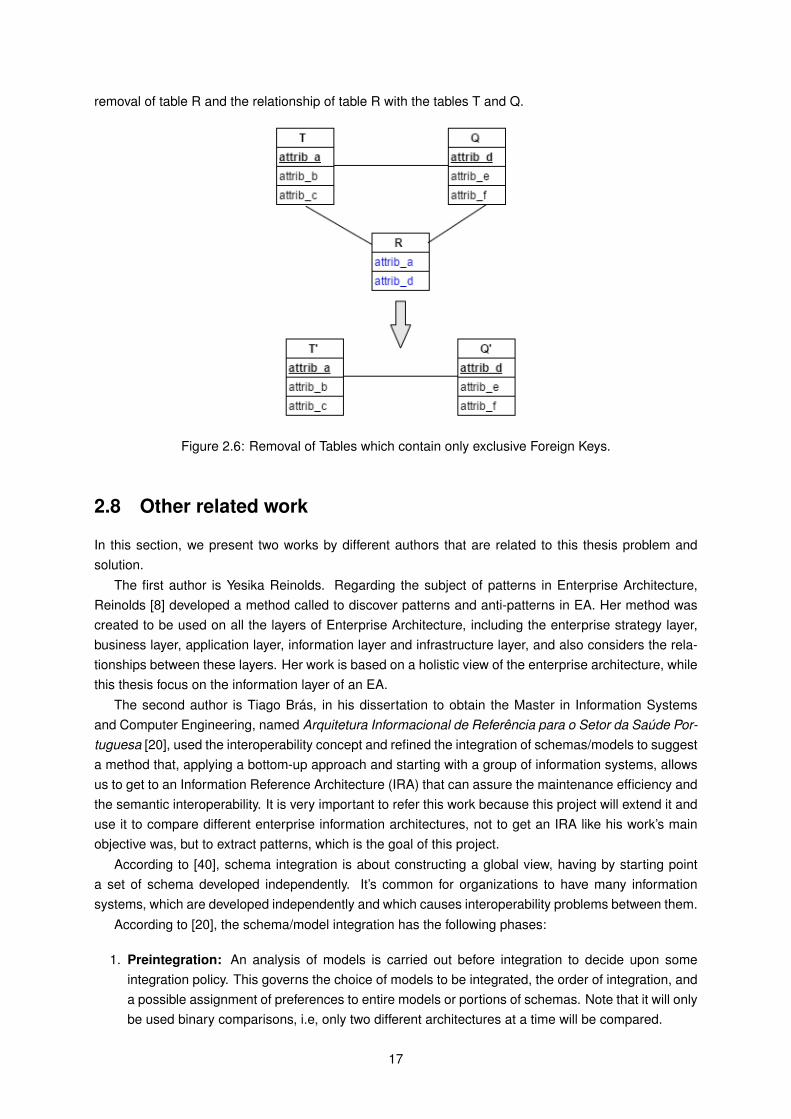
removal of table R and the relationship of table R with the tables T and Q.
Figure 2.6: Removal of Tables which contain only exclusive Foreign Keys.
2.8 Other related work
In this section, we present two works by different authors that are related to this thesis problem andsolution.
The first author is Yesika Reinolds. Regarding the subject of patterns in Enterprise Architecture,Reinolds [8] developed a method called to discover patterns and anti-patterns in EA. Her method wascreated to be used on all the layers of Enterprise Architecture, including the enterprise strategy layer,business layer, application layer, information layer and infrastructure layer, and also considers the rela-tionships between these layers. Her work is based on a holistic view of the enterprise architecture, whilethis thesis focus on the information layer of an EA.
The second author is Tiago Brás, in his dissertation to obtain the Master in Information Systemsand Computer Engineering, named Arquitetura Informacional de Referência para o Setor da Saúde Por-tuguesa [20], used the interoperability concept and refined the integration of schemas/models to suggesta method that, applying a bottom-up approach and starting with a group of information systems, allowsus to get to an Information Reference Architecture (IRA) that can assure the maintenance efficiency andthe semantic interoperability. It is very important to refer this work because this project will extend it anduse it to compare different enterprise information architectures, not to get an IRA like his work’s mainobjective was, but to extract patterns, which is the goal of this project.
According to [40], schema integration is about constructing a global view, having by starting pointa set of schema developed independently. It’s common for organizations to have many informationsystems, which are developed independently and which causes interoperability problems between them.
According to [20], the schema/model integration has the following phases:
1. Preintegration: An analysis of models is carried out before integration to decide upon someintegration policy. This governs the choice of models to be integrated, the order of integration, anda possible assignment of preferences to entire models or portions of schemas. Note that it will onlybe used binary comparisons, i.e, only two different architectures at a time will be compared.
17
Global strategies for integration, namely, the amount of designer interaction and the number ofschemas to be integrated at one time, are also decided in this phase. Collection of additional infor-mation relevant to integration, such as assertions or constraints among views, is also consideredto be a part of this phase.
2. Comparison of the Models: Models are analyzed and compared to determine the mappingamong concepts and detect possible conflicts. Inter-schema properties may be discovered whilecomparing models.
Giving two models S1 and S2, having a match means that for each concept in S1, we try to finda concept in S2 that it will be semantically similar. In this model matching phase, we may find thefollowing heterogeneity:
• Syntactic Heterogeneity: differences at the level of the formats used in the representation ofthe elements;
• Structural Heterogeneity: differences at the level of the types and structures used to representelements;
• Semantic Heterogeneity: differences in the interpretations that various people make of oneelement;
• System Heterogeneity: differences at the level of the system architectures, operation sys-tems, hardware types, among others.
2.1 Similarity between IE According to [20] and [41], two IE are similar if they share a set ofcharacteristics between them. Formally, we can quantify this similarity in the following way:
• Similarity(A,B) ∈ [0...1];
• Similarity(A,B) = 1: the two IE are equal;
• Similarity(A,B) = 0: the two IE don’t have common characteristics between themselves;
• 0 < Similarity(A,B) < 1: the two IE are not 100% equal, but they have some commoncharacteristics.
2.2 Similarity Rules According to [42], there is a set of rules to verify the existence of similaritybetween IE of different models. Note that these rules are grouped by order of importance and thatnone of them can, by itself, take any definitive conclusion of the similarity between the IE. Therelevant rules for this work are:
Group 1 - Assured Equality
• Rule 1 - If two IE have the same Uniform Resource Identifier (URI), they are equal;
• Rule 2 - If two IE have the same instances, they are equal.
Group 2 - Terminological Similarity - compares the IA’s labels.
• Rule 3 - If the name of two IE is the same or similar, it is likely that the two IE are equal orsimilar.
Group 3 - Internal Structure Similarity - compares the internal structure of the IE.
• Rule 4 - If the attributes of two IE are equal, it is likely that the two IE are also equal;
18
• Rule 5 - If the description of two IE is similar, it is likely that the two IE are also similar.
Group 4 - Structure and Extension Similarity - Compares the external structure of the IE (rules 6-9)and compares the instances of the IE (rules 10-12).
• Rule 6 - If the hierarchical path to the IE is equal, the compared IE are similar;
• Rule 7 - If the super entities are the same, the compared IE are similar;
• Rule 8 - If the sub entities are the same, the compared IE are similar;
• Rule 9 - If two IE have equal “sisters IE”, the compared IE are similar;
• Rule 10 - If two instances have the same “mother IE”, they are similar;
• Rule 11 - IE that have equal instance quantity are similar;
• Rule 12 - If two instances are connected to another instance through the same property, theyare similar among themselves.
2.3 Model Matching Process To get to a correct matching we shouldn’t use one of the rules, buta process that uses various of the rules mentioned above.
In [20] and [42], it is suggested a matching process between models, which has the following steps:
(a) Given two models, we want to calculate the similarities between any pair of IE;
(b) Choose a pair of IE to be compared;
(c) Iterate, in order, for all the similarity rule groups defined above and apply, at maximum, onerule of each group;
(d) Sum weights of the rules applied;
(e) When sum of weights is higher than the cut-off (0.75), IE are considered correspondent andthe process ends;
(f) If at the end of the process, the value obtained is lower than the cut-off (0.75), IE are notconsidered correspondent.
To each similarity rule, it is assigned a weight between 0 and 1.
At the end of this process, a matrix of similarity is obtained with the values of similarity for the IEthat were compared. This process has a minimum value to conclude that two IE are similar namedcut-off. By analyzing this matrix, all the pairs that have values below this cut-off are discarded.There is no consensual value in the scientific community, since it depends on the context this valueneeds to be applied on.
3. Conforming the Models: Once conflicts are detected, an effort is made to resolve them so thatthe merging of various models is possible. Automatic conflict resolution is generally not feasible;close interaction with designers and users is required before compromises can be achieved in anyreal-life integration activity.
4. Merging of the Models: Now the models are ready to be unified, giving rise to some intermediateintegrated model(s). We have the following rules in the unification of models:
• Rule 1 - If two IE in two different models are a match, the result of the unification is a uniqueIE that makes reference to the two original concepts.
• Rule 2 - If an IE in a "A" model is a specialization of a B IE in a "B" model, the result of theunification is the establishment of a relation of specialization between A and B in a new "E"model.
19

2.9 Discussion
This chapter presented the state-of-the-art for Enterprise Information Architecture and patterns in gen-eral, as well as a practical approach to abstract concepts to a higher level, to be used in the methodproposed. It also explained the UML language that will be used in this work for representing EnterpriseInformation Architectures, since it is a standard notation for software design and flexible.
The idea was to provide a knowledge background of the concepts used in the sections 3, 4 and 5 ofthis work. It hopes to serve as a guideline of thoughts on understanding the use and the importance ofpatterns in Enterprise Information Architectures.
20
Chapter 3
Solution Proposal
The main goal of this thesis is the:
Development of a method to create an Enterprise Information Architecture Patterns andAnti-Patterns Catalog as a categorization of recurring issues and its proposed solutions.
Thus, our work is a pattern-based approach to improve currently existing methods for future EIAprojects of the PA based on previous successful projects (that have similar context). The objectives ofthis work are listed below:
• Identification of correspondences between IE of different information architectures and identifica-tion of IE attributes between different Enterprise Information Architectures from AMA;
• Identify common problems in this specific industry concerning Enterprise Information Architectureand extract the patterns;
• Creation of an AMA’s EIA Patterns Catalog;
• Implement solutions to this specific industry based on historical data analyzed and informationnecessary for optimized architecture design decisions;
• Reduce the costs for creating a Patterns Catalog, by reducing the number of human resourcesnecessary to develop it.
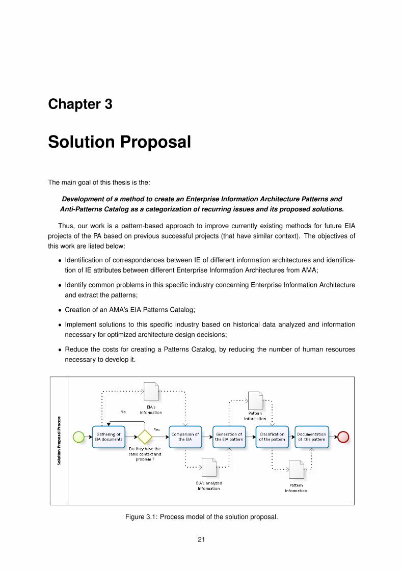
Figure 3.1: Process model of the solution proposal.
21
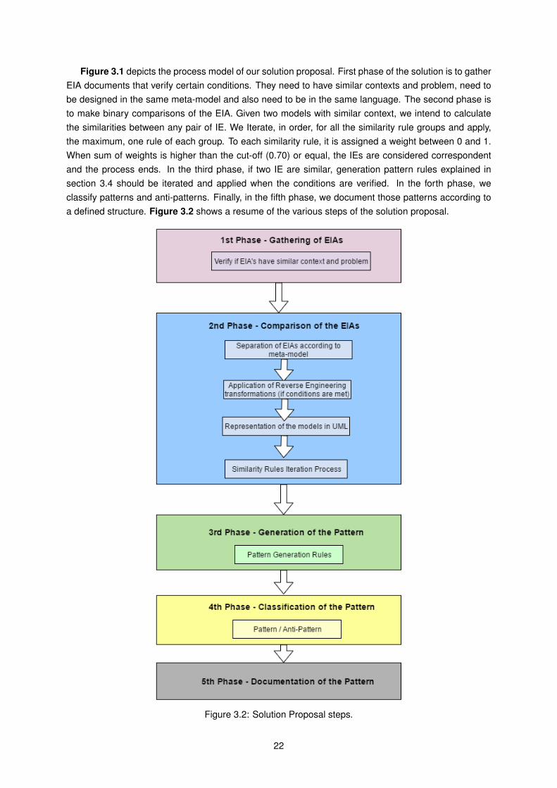
Figure 3.1 depicts the process model of our solution proposal. First phase of the solution is to gatherEIA documents that verify certain conditions. They need to have similar contexts and problem, need tobe designed in the same meta-model and also need to be in the same language. The second phase isto make binary comparisons of the EIA. Given two models with similar context, we intend to calculatethe similarities between any pair of IE. We Iterate, in order, for all the similarity rule groups and apply,the maximum, one rule of each group. To each similarity rule, it is assigned a weight between 0 and 1.When sum of weights is higher than the cut-off (0.70) or equal, the IEs are considered correspondentand the process ends. In the third phase, if two IE are similar, generation pattern rules explained insection 3.4 should be iterated and applied when the conditions are verified. In the forth phase, weclassify patterns and anti-patterns. Finally, in the fifth phase, we document those patterns according toa defined structure. Figure 3.2 shows a resume of the various steps of the solution proposal.
Figure 3.2: Solution Proposal steps.
22
3.1 1st Phase - Gathering of EIA documents
First, we need to gather all the Enterprise Information Architecture documents that we will later analyze.In this phase, it is important to analyze different EIA documents so to find architectures that have similarcontexts and functions.
The architecture needs to be designed in the same meta-model and also needs to have a similarcontext and a similar problem. They cannot be compared to find patterns if they don’t meet theseconditions.
The architectures should preferentially be represented in UML, as explained in section 2.4.3 of thiswork. If not, the modeling of the information systems may be necessary in the next phase to conceptu-alize and to have a formal representation of the IS. The architectures can only proceed to comparison ifthey have the same meta-model (for this thesis, it is UML, explained in section 2.4), as well as the samecontext and problems. It is also relevant to mention that the two EIA that will be compared, need to bein the same language. If they are not, they should be translated to English.
In order to understand the architectures that are analyzed, it is necessary to gather information aboutthem. In this phase, one must note that the architectures have a considerable amount of information,which requires some considerable effort at the beginning [43].
Once we have defined which Enterprise Information Architectures will be used, and once we haveconfirmed that they have the same context and problem, we can proceed to the second phase.
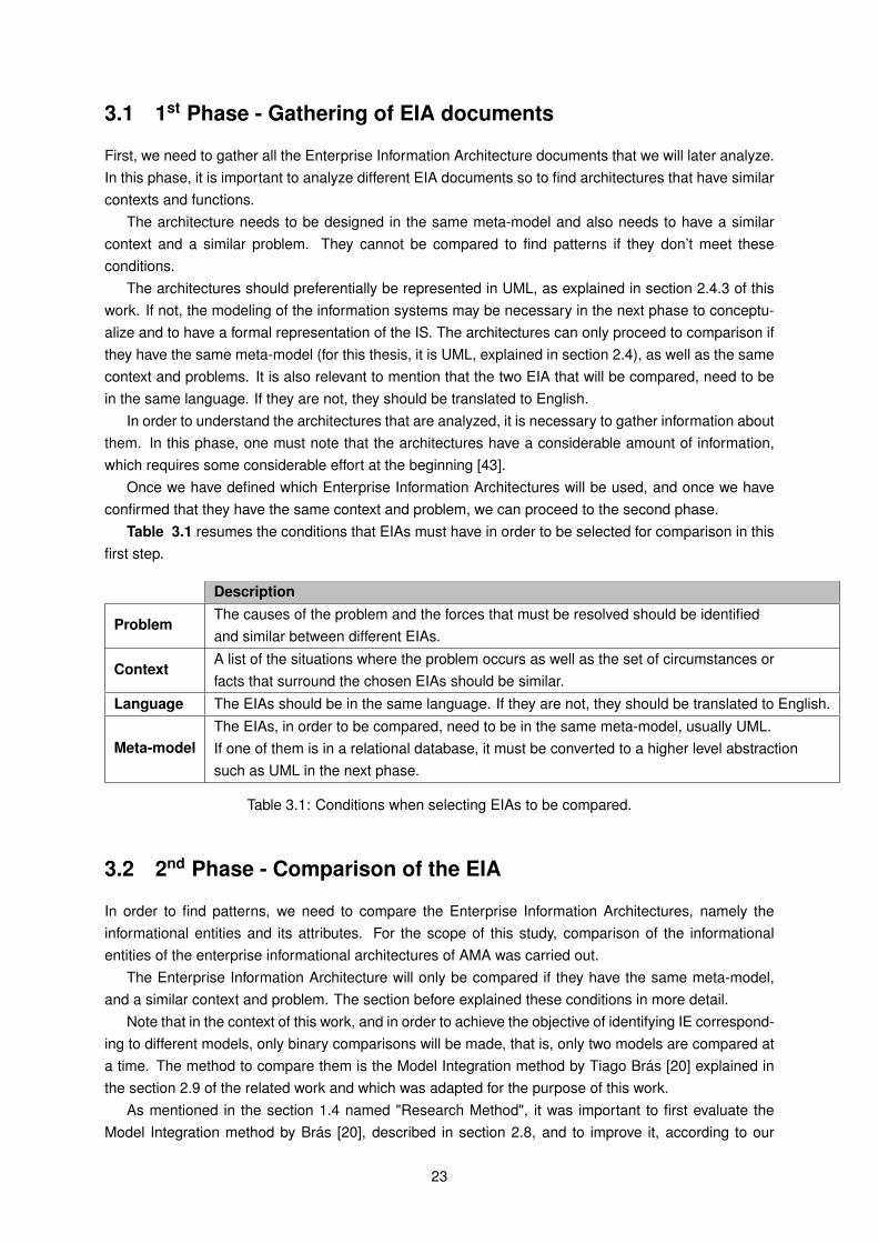
Table 3.1 resumes the conditions that EIAs must have in order to be selected for comparison in thisfirst step.
Description
ProblemThe causes of the problem and the forces that must be resolved should be identifiedand similar between different EIAs.
ContextA list of the situations where the problem occurs as well as the set of circumstances orfacts that surround the chosen EIAs should be similar.
Language The EIAs should be in the same language. If they are not, they should be translated to English.
Meta-modelThe EIAs, in order to be compared, need to be in the same meta-model, usually UML.If one of them is in a relational database, it must be converted to a higher level abstractionsuch as UML in the next phase.
Table 3.1: Conditions when selecting EIAs to be compared.
3.2 2nd Phase - Comparison of the EIA
In order to find patterns, we need to compare the Enterprise Information Architectures, namely theinformational entities and its attributes. For the scope of this study, comparison of the informationalentities of the enterprise informational architectures of AMA was carried out.
The Enterprise Information Architecture will only be compared if they have the same meta-model,and a similar context and problem. The section before explained these conditions in more detail.
Note that in the context of this work, and in order to achieve the objective of identifying IE correspond-ing to different models, only binary comparisons will be made, that is, only two models are compared ata time. The method to compare them is the Model Integration method by Tiago Brás [20] explained inthe section 2.9 of the related work and which was adapted for the purpose of this work.
As mentioned in the section 1.4 named "Research Method", it was important to first evaluate theModel Integration method by Brás [20], described in section 2.8, and to improve it, according to our
23
needs. As such, we used one of the phases of Brás’ method, called "Comparison of the Models" forthis second phase of our method. The improvements were the addition of three more rules that wereconsidered relevant, with a total of 15 different similarity rules. We also made a division of the similarityrules that should be used according to the model representation of the EIAs.
In this second phase of our method to compare EIA patterns, first it’s necessary to define the conceptof two matching IEs in this work, which is the following:
Matching IEs: Giving two IEs, IE1 and IE2, having a match means that for each concept inIE1, we try to find a concept in IE2 that it will be semantically similar.
Two names are correspondent if they have the same or synonymous labels, or if they have the sameUniform Resource Identifier (URI), or if the name correspondence techniques allow us to establish whichare the same or similar. To verify if two IE have the same name or are similar, it’s necessary to use aalgorithm to calculate it, such as Levenshtein Metric, Smith Waterman, JaroMetric, among others [44].
However, before calculating any type of name similarity, it is necessary to verify if some words aresynonyms or antonyms. If both words are synonyms, them these words have 100% similarity and if theyare antonyms, their similarity is 0%. Also, in the case that some words prepositions or conjunctions, thesimilarity of these words is not calculated.
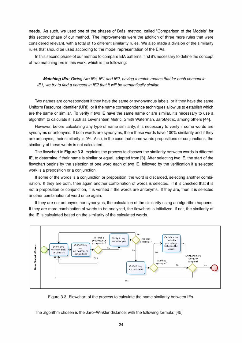
The flowchart in Figure 3.3. explains the process to discover the similarity between words in differentIE, to determine if their name is similar or equal, adapted from [8]. After selecting two IE, the start of theflowchart begins by the selection of one word each of two IE, followed by the verification if a selectedwork is a preposition or a conjunction.
If some of the words is a conjunction or preposition, the word is discarded, selecting another combi-nation. If they are both, then again another combination of words is selected. If it is checked that it isnot a preposition or conjunction, it is verified if the words are antonyms. If they are, then it is selectedanother combination of word once again.
If they are not antonyms nor synonyms, the calculation of the similarity using an algorithm happens.If they are more combination of words to be analyzed, the flowchart is initialized, if not, the similarity ofthe IE is calculated based on the similarity of the calculated words.
Figure 3.3: Flowchart of the process to calculate the name similarity between IEs.
The algorithm chosen is the Jaro–Winkler distance, with the following formula: [45]
24
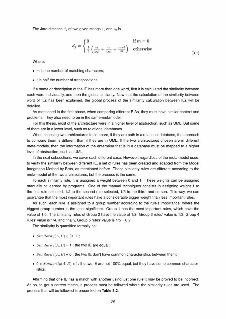
The Jaro distance dj of two given strings s1 and s2 is
(3.1)
Where:
• m is the number of matching characters;
• t is half the number of transpositions.
If a name or description of the IE has more than one word, first it is calculated the similarity betweeneach word individually, and then the global similarity. Now that the calculation of the similarity betweenword of IEs has been explained, the global process of the similarity calculation between IEs will bedetailed.
As mentioned in the first phase, when comparing different EIAs, they must have similar context andproblems. They also need to be in the same-metamodel.
For this thesis, most of the architecture were in a higher level of abstraction, such as UML. But someof them are in a lower level, such as relational databases.
When choosing two architectures to compare, if they are both in a relational database, the approachto compare them is different than if they are in UML. If the two architectures chosen are in differentmeta-models, then the information of the enterprise that is in a database must be mapped to a higherlevel of abstraction, such as UML.
In the next subsections, we cover each different case. However, regardless of the meta-model used,to verify the similarity between different IE, a set of rules has been created and adapted from the ModelIntegration Method by Brás, as mentioned before. These similarity rules are different according to themeta-model of the two architectures, but the process is the same.
To each similarity rule, it is assigned a weight between 0 and 1. These weights can be assignedmanually or learned by programs. One of the manual techniques consists in assigning weight 1 tothe first rule selected, 1/2 to the second rule selected, 1/3 to the third, and so son. This way, we canguarantee that the most important rules have a considerable bigger weight than less important rules.
As such, each rule is assigned to a group number according to the rule’s importance, where thebiggest group number is the least significant. Group 1 has the most important rules, which have thevalue of 1.0. The similarity rules of Group 2 have the value of 1/2. Group 3 rules’ value is 1/3, Group 4rules’ value is 1/4, and finally, Group 5 rules’ value is 1/5 = 0.2.
The similarity is quantified formally as:
• Similarity(A,B) ∈ [0...1];
• Similarity(A,B) = 1 : the two IE are equal;
• Similarity(A,B) = 0 : the two IE don’t have common characteristics between them;
• 0 < Similarity(A,B) < 1: the two IE are not 100% equal, but they have some common character-istics.
Affirming that one IE has a match with another using just one rule it may be proved to be incorrect.As so, to get a correct match, a process most be followed where the similarity rules are used. Theprocess that will be followed is presented on Table 3.2.
25
Order Process Description1 Given two models with similar context, we intend to calculate the similarities between any pair of IE.2 Choose a pair of IE to be compared.3 Iterate, in order, for all the similarity rule groups and apply, the maximum, one rule of each group.4 Sum weights of the rules applied.
5When sum of weights is higher than the cut-off (0.70) or equal, the IEs are considered correspondentand the process ends.
6If at the end of the process, the value obtained is lower than the cut-off (0.70), IEs are notconsidered a match.
Table 3.2: Process Iteration of the Similarity Rules.
Regarding the attributes correspondence, we consider that two IE are correspondent if at least 70%of the attributes of an IE have correspondence in the attributes of another IE.
The cut-off value considered in [20] was 75% since it was considered to be high enough to not getfalse positives. This value is dependent of the context, since there is not a consensual value among thescientific community.
Initially, our value was also considered to be 75%. However, due to our several iterations of theDSRM, our experiments found that the best value for our work context is 70% since it was high enoughto not get false positives, but not as high as 75% and therefore, it allows to find more similarity betweendifferent informational entities.
At the end of the iteration, if the two IE are concluded to be a match, we need to generate the pattern,with will be explained in the next phase.
This iteration process has different similarity rules according to the meta-model of the two selectedarchitectures. In the next subsections, we will cover for each case.
Figure 3.4 shows the flowchart for applying the similarity rules according to the EIAs that wheregathered. If they are in the same meta-model, they can either be in a relation database or in a highabstraction level such as UML. If only one of the two EIAs to be compared is in a relational database,then reverse engineering must be used.
Figure 3.4: Application of the Similarity Rules according to meta-model.
26
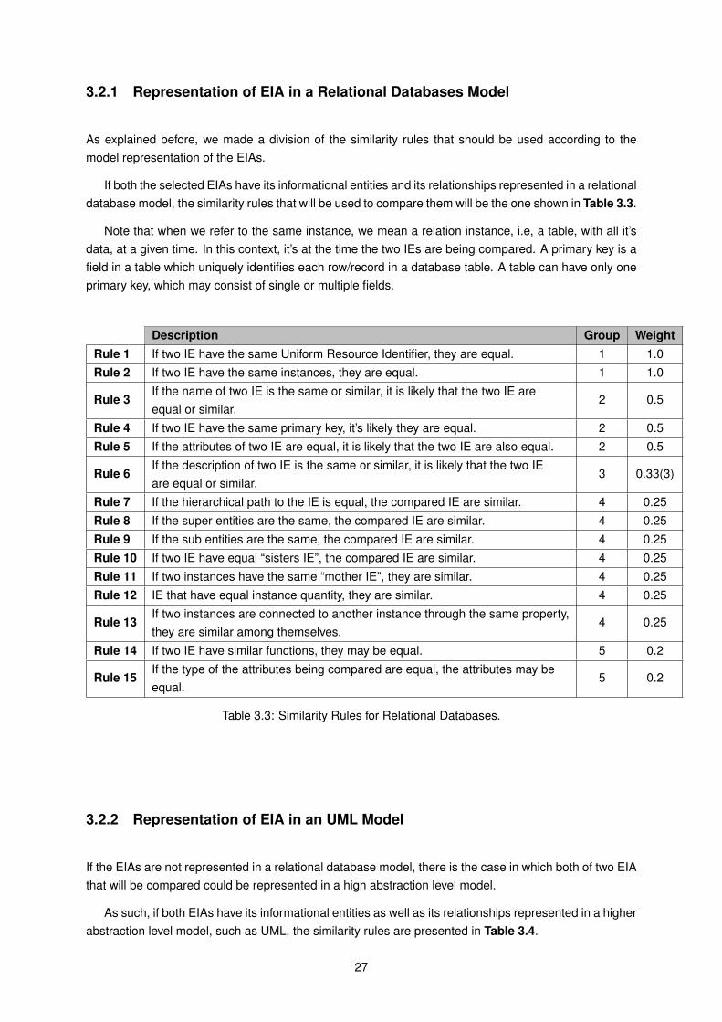
3.2.1 Representation of EIA in a Relational Databases Model
As explained before, we made a division of the similarity rules that should be used according to themodel representation of the EIAs.
If both the selected EIAs have its informational entities and its relationships represented in a relationaldatabase model, the similarity rules that will be used to compare them will be the one shown in Table 3.3.
Note that when we refer to the same instance, we mean a relation instance, i.e, a table, with all it’sdata, at a given time. In this context, it’s at the time the two IEs are being compared. A primary key is afield in a table which uniquely identifies each row/record in a database table. A table can have only oneprimary key, which may consist of single or multiple fields.
Description Group WeightRule 1 If two IE have the same Uniform Resource Identifier, they are equal. 1 1.0Rule 2 If two IE have the same instances, they are equal. 1 1.0
Rule 3If the name of two IE is the same or similar, it is likely that the two IE areequal or similar.
2 0.5
Rule 4 If two IE have the same primary key, it’s likely they are equal. 2 0.5Rule 5 If the attributes of two IE are equal, it is likely that the two IE are also equal. 2 0.5
Rule 6If the description of two IE is the same or similar, it is likely that the two IEare equal or similar.
3 0.33(3)
Rule 7 If the hierarchical path to the IE is equal, the compared IE are similar. 4 0.25Rule 8 If the super entities are the same, the compared IE are similar. 4 0.25Rule 9 If the sub entities are the same, the compared IE are similar. 4 0.25Rule 10 If two IE have equal “sisters IE”, the compared IE are similar. 4 0.25Rule 11 If two instances have the same “mother IE”, they are similar. 4 0.25Rule 12 IE that have equal instance quantity, they are similar. 4 0.25
Rule 13If two instances are connected to another instance through the same property,they are similar among themselves.
4 0.25
Rule 14 If two IE have similar functions, they may be equal. 5 0.2
Rule 15If the type of the attributes being compared are equal, the attributes may beequal.
5 0.2
Table 3.3: Similarity Rules for Relational Databases.
3.2.2 Representation of EIA in an UML Model
If the EIAs are not represented in a relational database model, there is the case in which both of two EIAthat will be compared could be represented in a high abstraction level model.
As such, if both EIAs have its informational entities as well as its relationships represented in a higherabstraction level model, such as UML, the similarity rules are presented in Table 3.4.
27
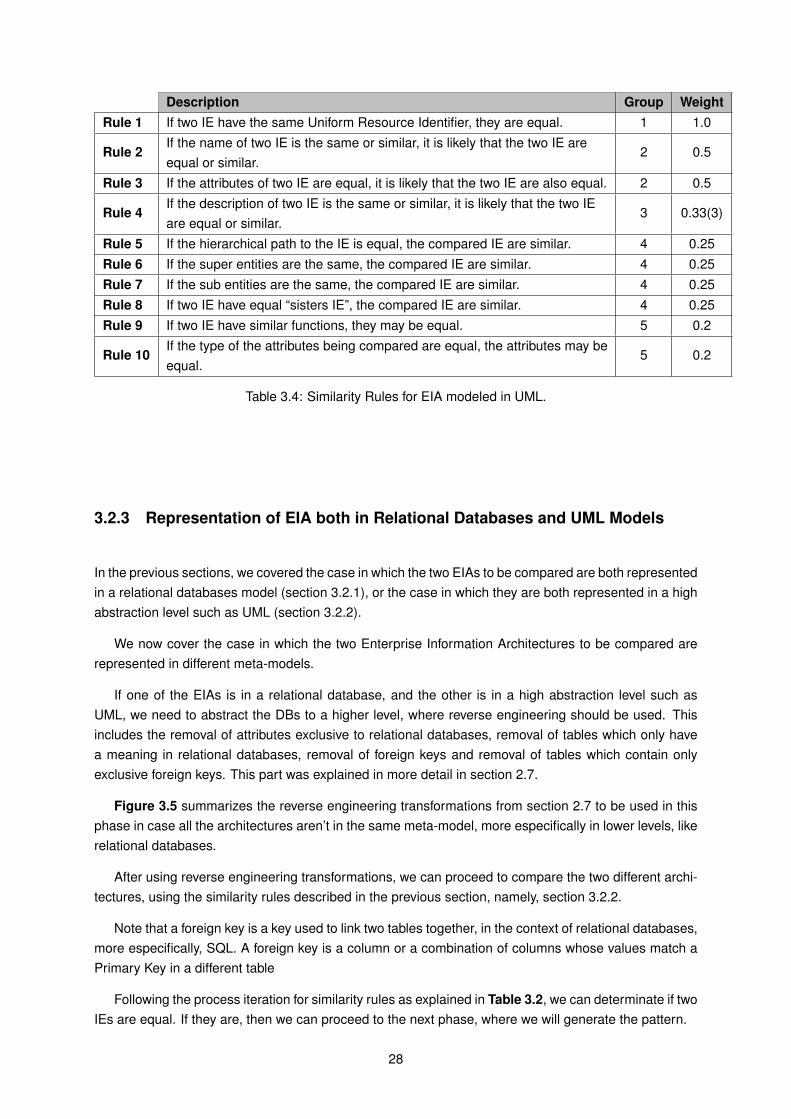
Description Group WeightRule 1 If two IE have the same Uniform Resource Identifier, they are equal. 1 1.0
Rule 2If the name of two IE is the same or similar, it is likely that the two IE areequal or similar.
2 0.5
Rule 3 If the attributes of two IE are equal, it is likely that the two IE are also equal. 2 0.5
Rule 4If the description of two IE is the same or similar, it is likely that the two IEare equal or similar.
3 0.33(3)
Rule 5 If the hierarchical path to the IE is equal, the compared IE are similar. 4 0.25Rule 6 If the super entities are the same, the compared IE are similar. 4 0.25Rule 7 If the sub entities are the same, the compared IE are similar. 4 0.25Rule 8 If two IE have equal “sisters IE”, the compared IE are similar. 4 0.25Rule 9 If two IE have similar functions, they may be equal. 5 0.2
Rule 10If the type of the attributes being compared are equal, the attributes may beequal.
5 0.2
Table 3.4: Similarity Rules for EIA modeled in UML.
3.2.3 Representation of EIA both in Relational Databases and UML Models
In the previous sections, we covered the case in which the two EIAs to be compared are both representedin a relational databases model (section 3.2.1), or the case in which they are both represented in a highabstraction level such as UML (section 3.2.2).
We now cover the case in which the two Enterprise Information Architectures to be compared arerepresented in different meta-models.
If one of the EIAs is in a relational database, and the other is in a high abstraction level such asUML, we need to abstract the DBs to a higher level, where reverse engineering should be used. Thisincludes the removal of attributes exclusive to relational databases, removal of tables which only havea meaning in relational databases, removal of foreign keys and removal of tables which contain onlyexclusive foreign keys. This part was explained in more detail in section 2.7.
Figure 3.5 summarizes the reverse engineering transformations from section 2.7 to be used in thisphase in case all the architectures aren’t in the same meta-model, more especifically in lower levels, likerelational databases.
After using reverse engineering transformations, we can proceed to compare the two different archi-tectures, using the similarity rules described in the previous section, namely, section 3.2.2.
Note that a foreign key is a key used to link two tables together, in the context of relational databases,more especifically, SQL. A foreign key is a column or a combination of columns whose values match aPrimary Key in a different table
Following the process iteration for similarity rules as explained in Table 3.2, we can determinate if twoIEs are equal. If they are, then we can proceed to the next phase, where we will generate the pattern.
28
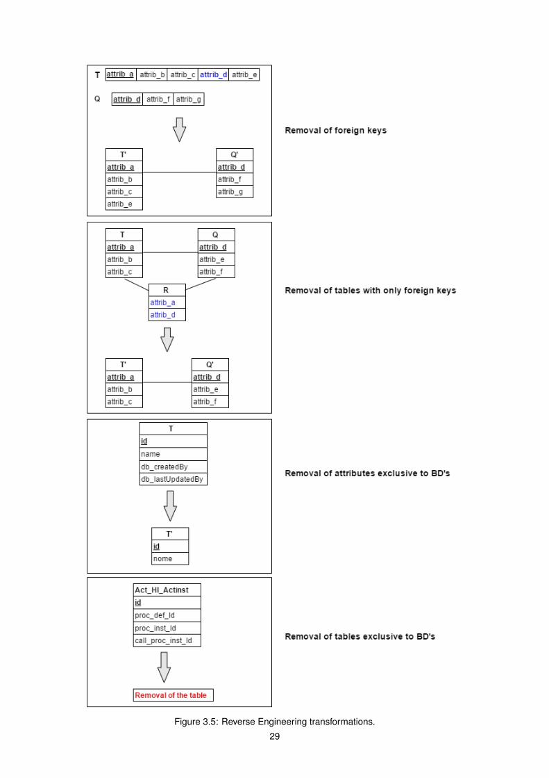
Figure 3.5: Reverse Engineering transformations.
29
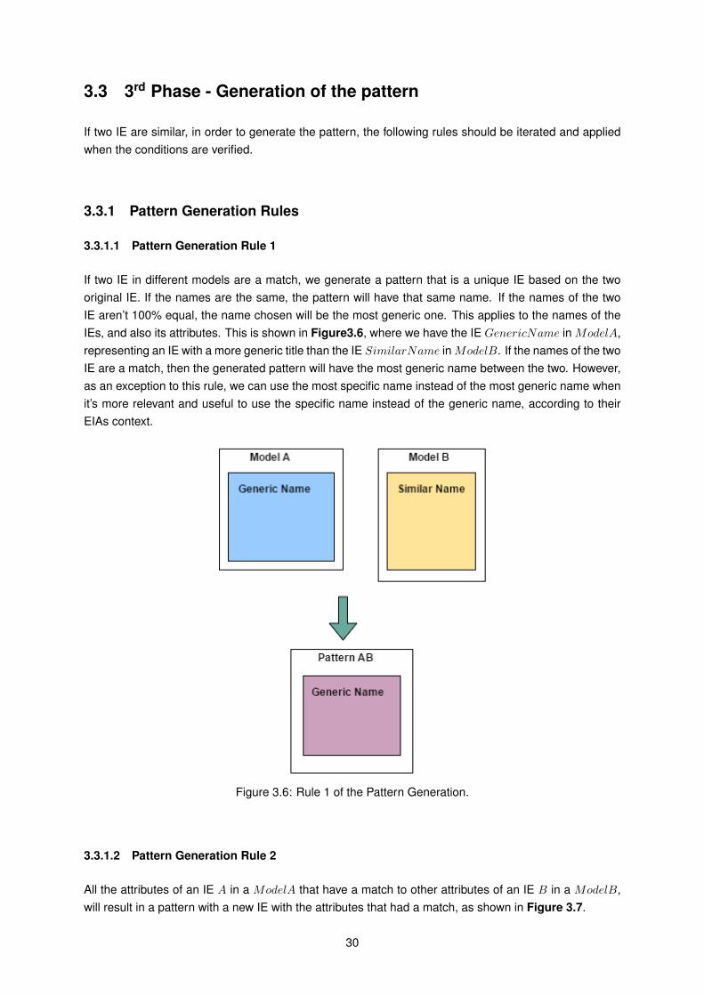
3.3 3rd Phase - Generation of the pattern
If two IE are similar, in order to generate the pattern, the following rules should be iterated and appliedwhen the conditions are verified.
3.3.1 Pattern Generation Rules
3.3.1.1 Pattern Generation Rule 1
If two IE in different models are a match, we generate a pattern that is a unique IE based on the twooriginal IE. If the names are the same, the pattern will have that same name. If the names of the twoIE aren’t 100% equal, the name chosen will be the most generic one. This applies to the names of theIEs, and also its attributes. This is shown in Figure3.6, where we have the IE GenericName in ModelA,representing an IE with a more generic title than the IE SimilarName in ModelB. If the names of the twoIE are a match, then the generated pattern will have the most generic name between the two. However,as an exception to this rule, we can use the most specific name instead of the most generic name whenit’s more relevant and useful to use the specific name instead of the generic name, according to theirEIAs context.
Figure 3.6: Rule 1 of the Pattern Generation.
3.3.1.2 Pattern Generation Rule 2
All the attributes of an IE A in a ModelA that have a match to other attributes of an IE B in a ModelB,will result in a pattern with a new IE with the attributes that had a match, as shown in Figure 3.7.
30
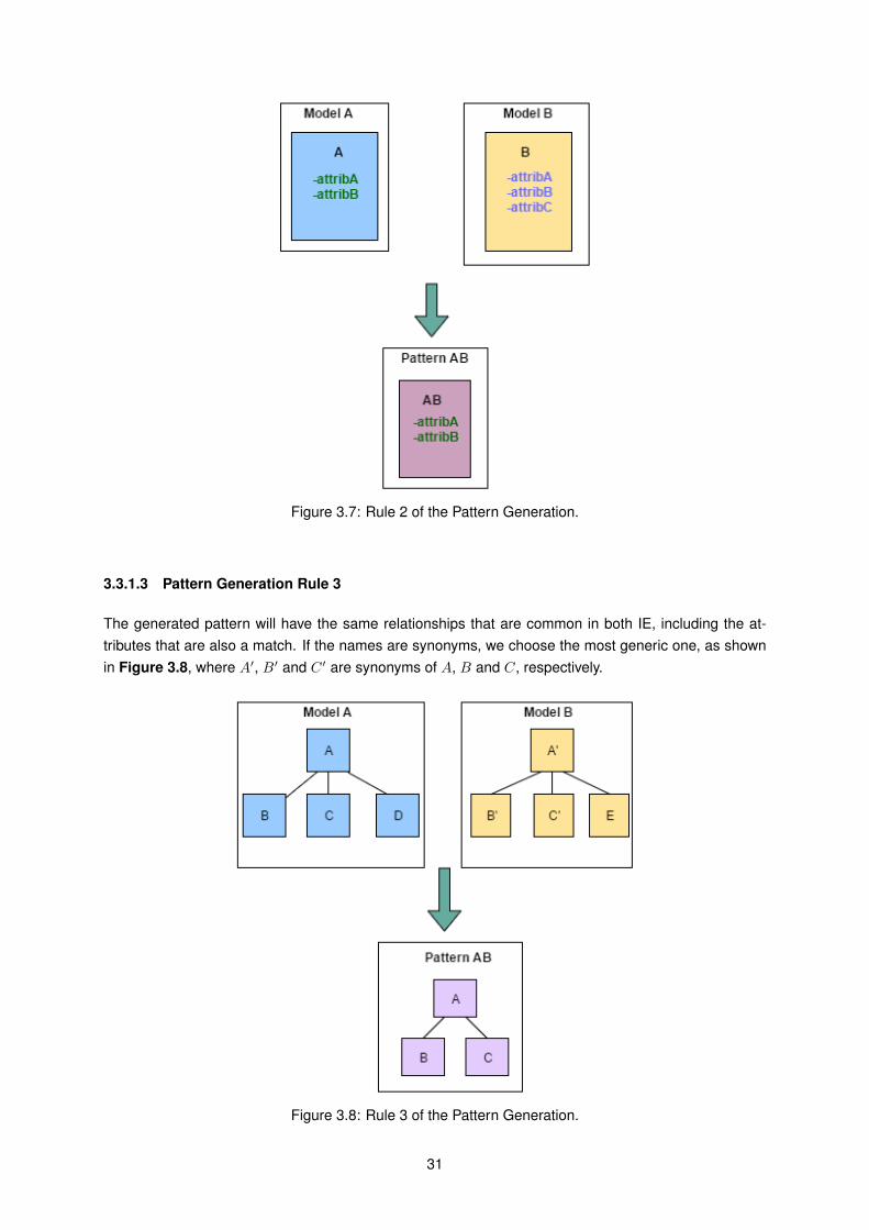
Figure 3.7: Rule 2 of the Pattern Generation.
3.3.1.3 Pattern Generation Rule 3
The generated pattern will have the same relationships that are common in both IE, including the at-tributes that are also a match. If the names are synonyms, we choose the most generic one, as shownin Figure 3.8, where A′, B′ and C ′ are synonyms of A, B and C, respectively.
Figure 3.8: Rule 3 of the Pattern Generation.
31
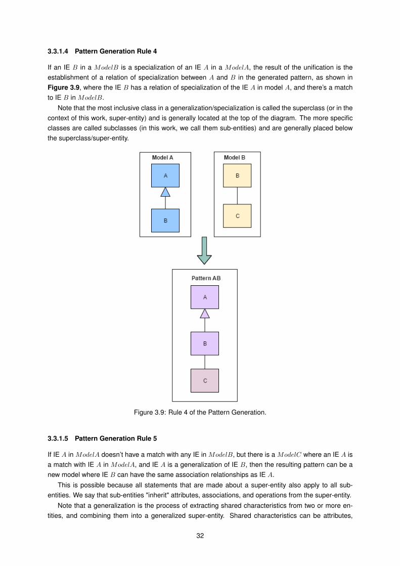
3.3.1.4 Pattern Generation Rule 4
If an IE B in a ModelB is a specialization of an IE A in a ModelA, the result of the unification is theestablishment of a relation of specialization between A and B in the generated pattern, as shown inFigure 3.9, where the IE B has a relation of specialization of the IE A in model A, and there’s a matchto IE B in ModelB.
Note that the most inclusive class in a generalization/specialization is called the superclass (or in thecontext of this work, super-entity) and is generally located at the top of the diagram. The more specificclasses are called subclasses (in this work, we call them sub-entities) and are generally placed belowthe superclass/super-entity.
Figure 3.9: Rule 4 of the Pattern Generation.
3.3.1.5 Pattern Generation Rule 5
If IE A in ModelA doesn’t have a match with any IE in ModelB, but there is a ModelC where an IE A isa match with IE A in ModelA, and IE A is a generalization of IE B, then the resulting pattern can be anew model where IE B can have the same association relationships as IE A.
This is possible because all statements that are made about a super-entity also apply to all sub-entities. We say that sub-entities "inherit" attributes, associations, and operations from the super-entity.
Note that a generalization is the process of extracting shared characteristics from two or more en-tities, and combining them into a generalized super-entity. Shared characteristics can be attributes,
32

relationships/associations, or methods.This rule is summarized in Figure 3.10.
Figure 3.10: Rule 4 of the Pattern Generation.
.
3.4 4th Phase - Classification of the Pattern
We also need to reflect about the discovered patterns and realize if the patterns provide us relevant oradditional information.
Patterns have become accepted in many different disciplines, because it is better to use patternsthen to reinvent the wheel every time a problem has to be solved. That is exactly what patterns are allabout, they document knowledge about solutions to recurring problems in a way that it can be reused byothers having the same problem. Documenting patterns is not simply following an instruction but has tobe learned and trained.
We need to verify practical aspects about the usage of these patterns and to list the consequences touse them in the architecture. To list the consequences we can use the documentation or/and the people’sexperience. After that, we need to classify the consequences of the patterns. The classifications consistin two levels: positive or negative. To do the classification we must use the information about theconsequences previously collected.
Here we defined patterns and anti-patterns. In this phase, it is important that collaborators with ex-pertise in the Enterprise Information Architectures analyzed provide their validation and their conclusionregarding if the patterns are positive or negative. If the patterns are considered positive then they areclassified as a pattern. If they are considered to have negative consequences, we classify them asanti-patterns.
How exactly do we distinguish if a pattern is positive or negative? We need to analyze their implica-tions.
33

Description Consequencesis a piece of literature that describes a design problem and a general solutionfor the problem in a particular context.describes a particular recurring design problem that arises inspecific designcontexts and presents a well-proven solution for the problem.Patternis a general, reusable solution to a common problem in a given context.
Positive
describes a commonly occurring solution to a problem that generatesdecidedly negative consequences.is a negative solution that presents more problems than they address.documents a solution to a recurring problemin a specific context, whichhas proven not to work in practice.Anti-patternis just like a pattern, except that instead of a solution it gives somethingthat looks superficially like a solution but isn’t one.
Negative
Table 3.5: Classification of Patterns and Anti-patterns
Anti-Patterns highlight the most common problems that face the software industry and provide thetools to enable you to recognize these problems and to determine their underlying causes, while apattern describes a recurring design problem that arises in specific design contexts and presents awell-proven solution for the problem.
Table 3.5 shows the differences between a pattern and anti-pattern, using definitions by differentauthors. Brown et al. affirm that “an anti-pattern is a literary form that describes a commonly occurringsolution to a problem that generates decidedly negative consequences. The anti-pattern may be theresult of a manager or a developer not knowing any better, not having sufficient knowledge or experiencein solving a particular type of problem, or having applied a perfectly good pattern in the wrong context".He further affirms that when properly documented, an anti-pattern describes a general form, the primarycauses which led to the general form; symptoms describing how to recognize the general form; theconsequences of the general form; and a refactored solution describing how to change the AntiPatterninto a healthier situation [37].
Collaborators of the enterprise who are more aware of the information architectures should give theirperspective if they classify it as a pattern or an anti-pattern.
3.5 5th Phase - Documentation of the pattern in EIA Catalog
The pattern form selected for documenting patterns is important for the applicability of the patterns. Al-though, various pattern forms are known (some of the most popular were explained in the related worksection), there are five essential elements included in all of them, which are: identification, context, prob-lem, solution and consequences. Buschmann et al. [5] give an overview about these elements and theirpurpose. We adapted their documentation form. The way we organized our Information ArchitecturePatterns and Anti-Patterns catalog is as it follows:
1. Pattern/Anti-Pattern: Define if it is classified as a pattern or as an anti-pattern.
2. Pattern’s ID: An unique alphanumerical identifier.
3. Identification: Name and classification for identifying pattern. The name should be memorable,usable, and distinct. Additionally, it is important for creating a vocabulary for the domain underconsideration.
4. Context: Situation giving rise to a problem. No problem exists in a vacuum, there is alwaysa surrounding context. The context helps to determine where to use the pattern, and provides
34
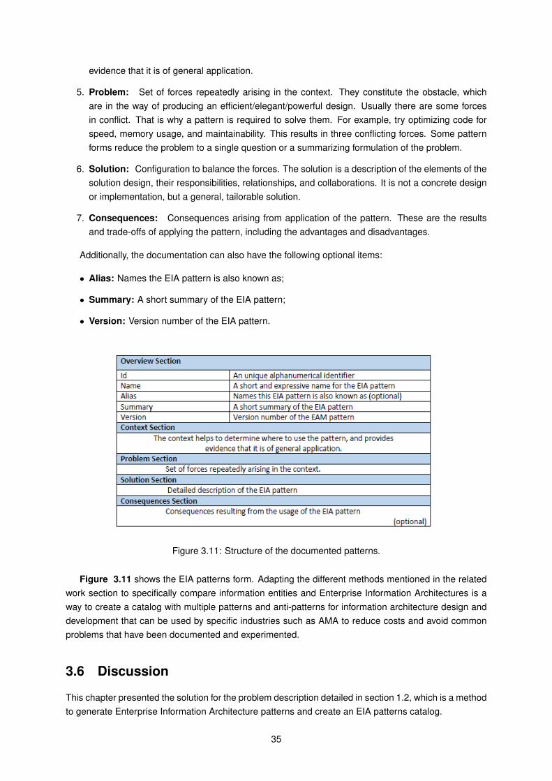
evidence that it is of general application.
5. Problem: Set of forces repeatedly arising in the context. They constitute the obstacle, whichare in the way of producing an efficient/elegant/powerful design. Usually there are some forcesin conflict. That is why a pattern is required to solve them. For example, try optimizing code forspeed, memory usage, and maintainability. This results in three conflicting forces. Some patternforms reduce the problem to a single question or a summarizing formulation of the problem.
6. Solution: Configuration to balance the forces. The solution is a description of the elements of thesolution design, their responsibilities, relationships, and collaborations. It is not a concrete designor implementation, but a general, tailorable solution.
7. Consequences: Consequences arising from application of the pattern. These are the resultsand trade-offs of applying the pattern, including the advantages and disadvantages.
Additionally, the documentation can also have the following optional items:
• Alias: Names the EIA pattern is also known as;
• Summary: A short summary of the EIA pattern;
• Version: Version number of the EIA pattern.
Figure 3.11: Structure of the documented patterns.
Figure 3.11 shows the EIA patterns form. Adapting the different methods mentioned in the relatedwork section to specifically compare information entities and Enterprise Information Architectures is away to create a catalog with multiple patterns and anti-patterns for information architecture design anddevelopment that can be used by specific industries such as AMA to reduce costs and avoid commonproblems that have been documented and experimented.
3.6 Discussion
This chapter presented the solution for the problem description detailed in section 1.2, which is a methodto generate Enterprise Information Architecture patterns and create an EIA patterns catalog.
35

The first phase of the solution is to gather EIA documents that verify certain conditions. They need tohave similar contexts and problem. The architecture also needs to be designed in the same meta-modeland also needs to be in the same language, preferable English.
The second phase is to make binary comparisons of the EIA. Given two models with similar context,we intend to calculate the similarities between any pair of IE. If one of the EIAs is in a relational database,and the other is in a high abstraction level such as UML, we need to abstract the DBs to a higher level,where reverse engineering is used. If two IE are similar, in order to generate the pattern, generationpattern rules explained in section 3.3 should be iterated and applied when the conditions are verified.In the forth phase, we classify patterns and anti-patterns. Finally, in the fifth phase, we document thosepatterns according to a defined structure presented in section 3.5.
By applying these steps in EIAs with similar context, we proposed to create an EIA patterns catalogfor AMA.
36
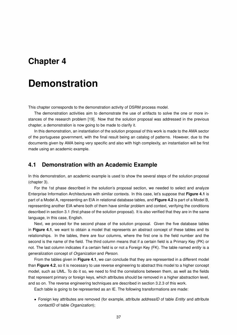
Chapter 4
Demonstration
This chapter corresponds to the demonstration activity of DSRM process model.The demonstration activities aim to demonstrate the use of artifacts to solve the one or more in-
stances of the research problem [19]. Now that the solution proposal was addressed in the previouschapter, a demonstration is now going to be made to clarify it.
In this demonstration, an instantiation of the solution proposal of this work is made to the AMA sectorof the portuguese government, with the final result being an catalog of patterns. However, due to thedocuments given by AMA being very specific and also with high complexity, an instantiation will be firstmade using an academic example.
4.1 Demonstration with an Academic Example
In this demonstration, an academic example is used to show the several steps of the solution proposal(chapter 3).
For the 1st phase described in the solution’s proposal section, we needed to select and analyzeEnterprise Information Architectures with similar contexts. In this case, let’s suppose that Figure 4.1 ispart of a Model A, representing an EIA in relational database tables, and Figure 4.2 is part of a Model B,representing another EIA where both of them have similar problem and context, verifying the conditionsdescribed in section 3.1 (first phase of the solution proposal). It is also verified that they are in the samelanguage, in this case, English.
Next, we proceed for the second phase of the solution proposal. Given the five database tablesin Figure 4.1, we want to obtain a model that represents an abstract concept of these tables and itsrelationships. In the tables, there are four columns, where the first one is the field number and thesecond is the name of the field. The third column means that if a certain field is a Primary Key (PK) ornot. The last column indicates if a certain field is or not a Foreign Key (FK). The table named entity is ageneralization concept of Organization and Person.
From the tables given in Figure 4.1, we can conclude that they are represented in a different modelthan Figure 4.2, so it is necessary to use reverse engineering to abstract this model to a higher conceptmodel, such as UML. To do it so, we need to find the correlations between them, as well as the fieldsthat represent primary or foreign keys, which attributes should be removed in a higher abstraction level,and so on. The reverse engineering techniques are described in section 3.2.3 of this work.
Each table is going to be represented as an IE. The following transformations are made:
• Foreign key attributes are removed (for example, attribute addressID of table Entity and attributecontactID of table Organization);
37
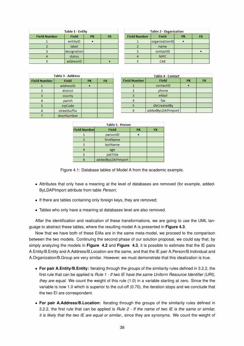
Figure 4.1: Database tables of Model A from the academic example.
• Attributes that only have a meaning at the level of databases are removed (for example, added-ByLDAPImport attribute from table Person;
• If there are tables containing only foreign keys, they are removed;
• Tables who only have a meaning at databases level are also removed.
After the identification and realization of these transformations, we are going to use the UML lan-guage to abstract these tables, where the resulting model A is presented in Figure 4.3.
Now that we have both of these EIAs are in the same meta-model, we proceed to the comparisonbetween the two models. Continuing the second phase of our solution proposal, we could say that, bysimply analyzing the models in Figure 4.2 and Figure 4.3, it is possible to estimate that the IE pairsA.Entity/B.Entity and A.Address/B.Location are the same, and that the IE pair A.Person/B.Individual andA.Organization/B.Group are very similar. However, we must demonstrate that this idealization is true.
• For pair A.Entity/B.Entity: Iterating through the groups of the similarity rules defined in 3.2.2, thefirst rule that can be applied is Rule 1 - If two IE have the same Uniform Resource Identifier (URI),they are equal. We count the weight of this rule (1.0) in a variable starting at zero. Since the thevariable is now 1.0 which is superior to the cut-off (0.70), the iteration stops and we conclude thatthe two EI are correspondent.
• For pair A.Address/B.Location: Iterating through the groups of the similarity rules defined in3.2.2, the first rule that can be applied is Rule 2 - If the name of two IE is the same or similar,it is likely that the two IE are equal or similar., since they are synonyms. We count the weight of
38
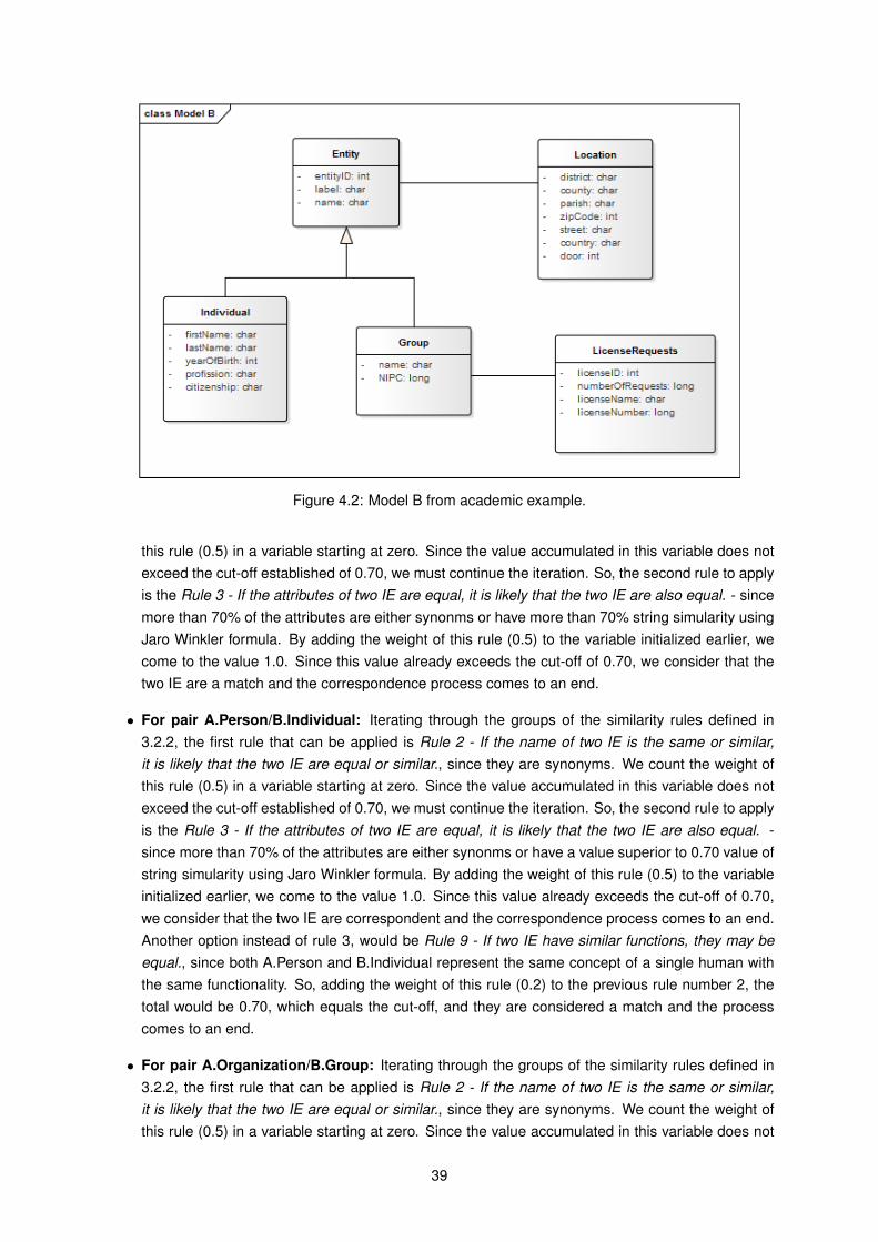
Figure 4.2: Model B from academic example.
this rule (0.5) in a variable starting at zero. Since the value accumulated in this variable does notexceed the cut-off established of 0.70, we must continue the iteration. So, the second rule to applyis the Rule 3 - If the attributes of two IE are equal, it is likely that the two IE are also equal. - sincemore than 70% of the attributes are either synonms or have more than 70% string simularity usingJaro Winkler formula. By adding the weight of this rule (0.5) to the variable initialized earlier, wecome to the value 1.0. Since this value already exceeds the cut-off of 0.70, we consider that thetwo IE are a match and the correspondence process comes to an end.
• For pair A.Person/B.Individual: Iterating through the groups of the similarity rules defined in3.2.2, the first rule that can be applied is Rule 2 - If the name of two IE is the same or similar,it is likely that the two IE are equal or similar., since they are synonyms. We count the weight ofthis rule (0.5) in a variable starting at zero. Since the value accumulated in this variable does notexceed the cut-off established of 0.70, we must continue the iteration. So, the second rule to applyis the Rule 3 - If the attributes of two IE are equal, it is likely that the two IE are also equal. -since more than 70% of the attributes are either synonms or have a value superior to 0.70 value ofstring simularity using Jaro Winkler formula. By adding the weight of this rule (0.5) to the variableinitialized earlier, we come to the value 1.0. Since this value already exceeds the cut-off of 0.70,we consider that the two IE are correspondent and the correspondence process comes to an end.Another option instead of rule 3, would be Rule 9 - If two IE have similar functions, they may beequal., since both A.Person and B.Individual represent the same concept of a single human withthe same functionality. So, adding the weight of this rule (0.2) to the previous rule number 2, thetotal would be 0.70, which equals the cut-off, and they are considered a match and the processcomes to an end.
• For pair A.Organization/B.Group: Iterating through the groups of the similarity rules defined in3.2.2, the first rule that can be applied is Rule 2 - If the name of two IE is the same or similar,it is likely that the two IE are equal or similar., since they are synonyms. We count the weight ofthis rule (0.5) in a variable starting at zero. Since the value accumulated in this variable does not
39
Figure 4.3: Model A after reverse engineering techniques, from academic example.
exceed the cut-off established of 0.70, we must continue the iteration. So, the second rule to applyis the rule 3 for the same reasons as mentioned previously. Other rules could also apply, but sincethe cut-off value is reached, the two IE are considered a match and the process ends.
• For pair A.Contact/B.LicenseRequests: There are no rules that apply to these IE pair, so weconclude that they are not a match.
Finally, we can now generate the pattern, which is the third phase of our solution proposal. We applythe pattern generation rules defined in the section 3.3.1, such as Rule 1 - if two IE in different modelsare a match, we generate a pattern that is a unique IE based on the two original IE. If the names are thesame, the pattern will have that same name. If the names of the two IE aren’t 100% equal, the namechosen will be the most generic one. This applies to the names of the IEs, and also its attributes.
We need also to apply Pattern Generation Rule 2 - All the attributes of an IE A in a ModelA that havea match to other attributes of an IE B in a ModelB, will result in a pattern with a new IE with the attributesthat had a match. - and Rule 3 The generated pattern will have the same relationships that are commonin both IE, including the attributes that are also a match. The attributes who had a match are the onesthat in the previous phase were concluded to be synonyms or to have more than 0.70 in Jaro Winklersimilarity.
The other Pattern Generation Rules presented in section 3.3.1 don’t apply to this case.The resulting pattern is represented in Figure 4.4.Next, we proceed to the forth phase. We need to analyze if this pattern has a positive or negative
consequences. Analyzing table 3.5 from section 3.4, we conclude that this pattern should be classified
40
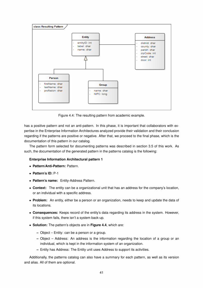
Figure 4.4: The resulting pattern from academic example.
has a positive pattern and not an anti-pattern. In this phase, it is important that collaborators with ex-pertise in the Enterprise Information Architectures analyzed provide their validation and their conclusionregarding if the patterns are positive or negative. After that, we proceed to the final phase, which is thedocumentation of this pattern in our catalog.
The pattern form selected for documenting patterns was described in section 3.5 of this work. Assuch, the documentation of the generated pattern in the patterns catalog is the following:
Enterprise Information Architectural pattern 1
• Pattern/Anti-Pattern: Pattern.
• Pattern’s ID: P-1
• Pattern’s name: Entity-Address Pattern.
• Context: The entity can be a organizational unit that has an address for the company’s location,or an individual with a specific address.
• Problem: An entity, either be a person or an organization, needs to keep and update the data ofits locations.
• Consequences: Keeps record of the entity’s data regarding its address in the system. However,if this system fails, there isn’t a system back-up.
• Solution: The pattern’s objects are in Figure 4.4, which are:
– Object – Entity: can be a person or a group.
– Object – Address: An address is the information regarding the location of a group or anindividual, which is kept in the information system of an organization.
– Entity has Address: The Entity unit uses Address to support its activities.
Additionally, the patterns catalog can also have a summary for each pattern, as well as its versionand alias. All of them are optional.
41
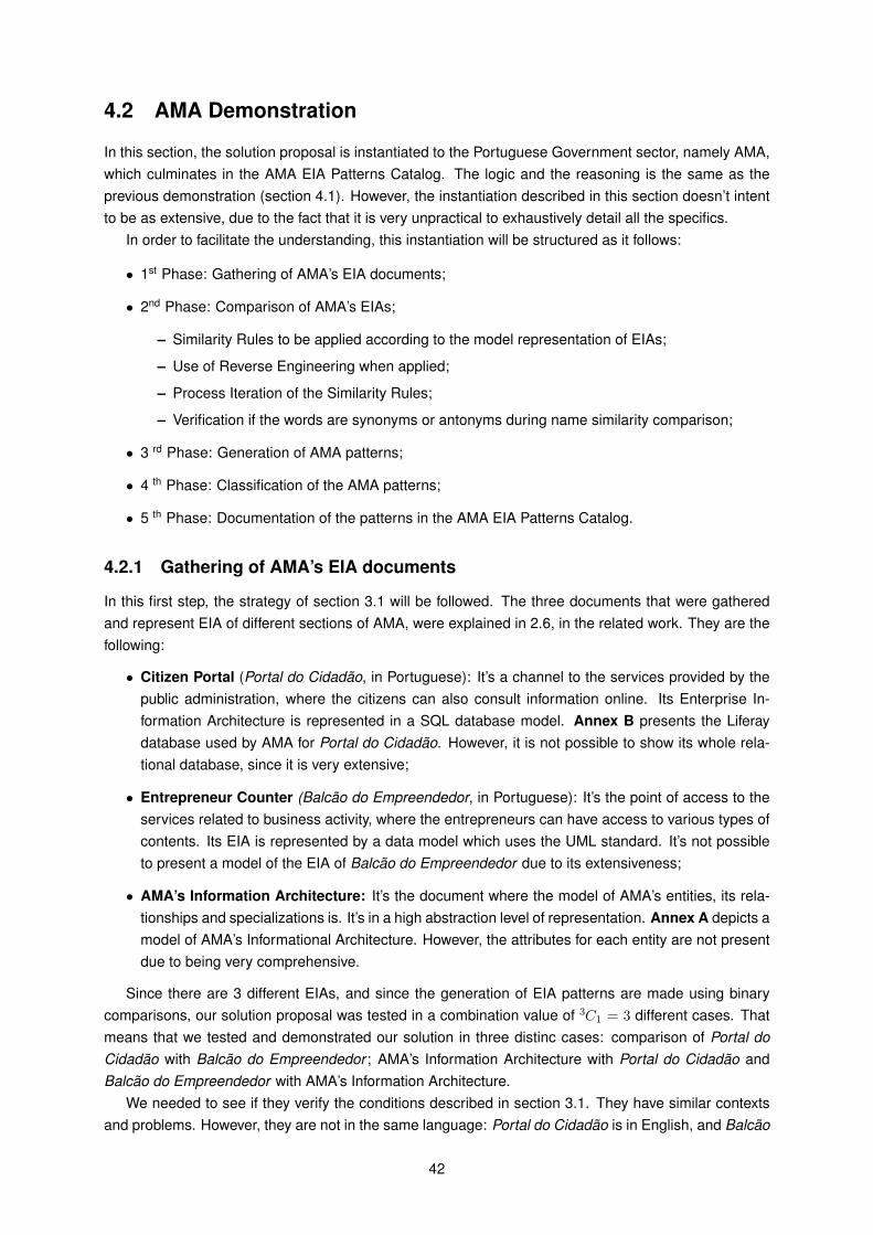
4.2 AMA Demonstration
In this section, the solution proposal is instantiated to the Portuguese Government sector, namely AMA,which culminates in the AMA EIA Patterns Catalog. The logic and the reasoning is the same as theprevious demonstration (section 4.1). However, the instantiation described in this section doesn’t intentto be as extensive, due to the fact that it is very unpractical to exhaustively detail all the specifics.
In order to facilitate the understanding, this instantiation will be structured as it follows:
• 1st Phase: Gathering of AMA’s EIA documents;
• 2nd Phase: Comparison of AMA’s EIAs;
– Similarity Rules to be applied according to the model representation of EIAs;
– Use of Reverse Engineering when applied;
– Process Iteration of the Similarity Rules;
– Verification if the words are synonyms or antonyms during name similarity comparison;
• 3 rd Phase: Generation of AMA patterns;
• 4 th Phase: Classification of the AMA patterns;
• 5 th Phase: Documentation of the patterns in the AMA EIA Patterns Catalog.
4.2.1 Gathering of AMA’s EIA documents
In this first step, the strategy of section 3.1 will be followed. The three documents that were gatheredand represent EIA of different sections of AMA, were explained in 2.6, in the related work. They are thefollowing:
• Citizen Portal (Portal do Cidadão, in Portuguese): It’s a channel to the services provided by thepublic administration, where the citizens can also consult information online. Its Enterprise In-formation Architecture is represented in a SQL database model. Annex B presents the Liferaydatabase used by AMA for Portal do Cidadão. However, it is not possible to show its whole rela-tional database, since it is very extensive;
• Entrepreneur Counter (Balcão do Empreendedor, in Portuguese): It’s the point of access to theservices related to business activity, where the entrepreneurs can have access to various types ofcontents. Its EIA is represented by a data model which uses the UML standard. It’s not possibleto present a model of the EIA of Balcão do Empreendedor due to its extensiveness;
• AMA’s Information Architecture: It’s the document where the model of AMA’s entities, its rela-tionships and specializations is. It’s in a high abstraction level of representation. Annex A depicts amodel of AMA’s Informational Architecture. However, the attributes for each entity are not presentdue to being very comprehensive.
Since there are 3 different EIAs, and since the generation of EIA patterns are made using binarycomparisons, our solution proposal was tested in a combination value of 3C1 = 3 different cases. Thatmeans that we tested and demonstrated our solution in three distinc cases: comparison of Portal doCidadão with Balcão do Empreendedor ; AMA’s Information Architecture with Portal do Cidadão andBalcão do Empreendedor with AMA’s Information Architecture.
We needed to see if they verify the conditions described in section 3.1. They have similar contextsand problems. However, they are not in the same language: Portal do Cidadão is in English, and Balcão
42
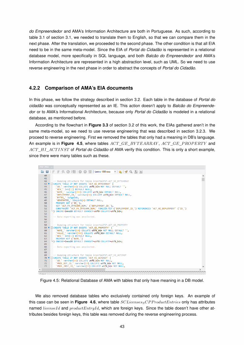
do Empreendedor and AMA’s Information Architecture are both in Portuguese. As such, according totable 3.1 of section 3.1, we needed to translate them to English, so that we can compare them in thenext phase. After the translation, we proceeded to the second phase. The other condition is that all EIAneed to be in the same meta-model. Since the EIA of Portal do Cidadão is represented in a relationaldatabase model, more specifically in SQL language, and both Balcão do Empreendedor and AMA’sInformation Architecture are represented in a high abstraction level, such as UML. So we need to usereverse engineering in the next phase in order to abstract the concepts of Portal do Cidadão.
4.2.2 Comparison of AMA’s EIA documents
In this phase, we follow the strategy described in section 3.2. Each table in the database of Portal docidadão was conceptually represented as an IE. This action doesn’t apply to Balcão do Empreende-dor or to AMA’s Informational Architecture, because only Portal do Cidadão is modeled in a relationaldatabase, as mentioned before.
According to the flowchart in Figure 3.3 of section 3.2 of this work, the EIAs gathered aren’t in thesame meta-model, so we need to use reverse engineering that was described in section 3.2.3. Weproceed to reverse engineering. First we removed the tables that only had a meaning in DB’s language.An example is in Figure 4.5, where tables ACT_GE_BY TEARRAY , ACT_GE_PROPERTY andACT_HI_ACTINST of Portal do Cidadão of AMA verify this condition. This is only a short example,since there were many tables such as these.
Figure 4.5: Relational Database of AMA with tables that only have meaning in a DB model.
We also removed database tables who exclusively contained only foreign keys. An example ofthis case can be seen in Figure 4.6, where table SCLicensesSCPProductEntries only has attributesnamed licenseId and productEntryId, which are foreign keys. Since the table doesn’t have other at-tributes besides foreign keys, this table was removed during the reverse engineering process.
43
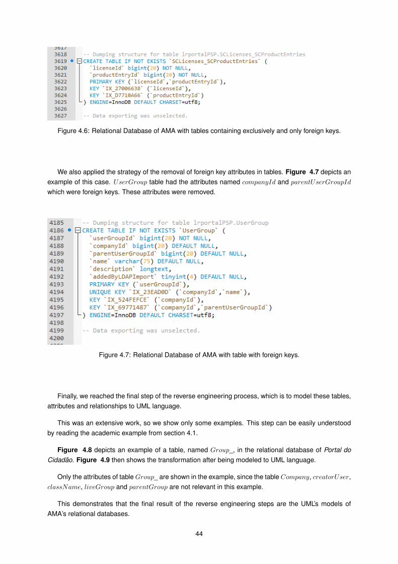
Figure 4.6: Relational Database of AMA with tables containing exclusively and only foreign keys.
We also applied the strategy of the removal of foreign key attributes in tables. Figure 4.7 depicts anexample of this case. UserGroup table had the attributes named companyId and parentUserGroupId
which were foreign keys. These attributes were removed.
Figure 4.7: Relational Database of AMA with table with foreign keys.
Finally, we reached the final step of the reverse engineering process, which is to model these tables,attributes and relationships to UML language.
This was an extensive work, so we show only some examples. This step can be easily understoodby reading the academic example from section 4.1.
Figure 4.8 depicts an example of a table, named Group_, in the relational database of Portal doCidadão. Figure 4.9 then shows the transformation after being modeled to UML language.
Only the attributes of table Group_ are shown in the example, since the table Company, creatorUser,className, liveGroup and parentGroup are not relevant in this example.
This demonstrates that the final result of the reverse engineering steps are the UML’s models ofAMA’s relational databases.
44
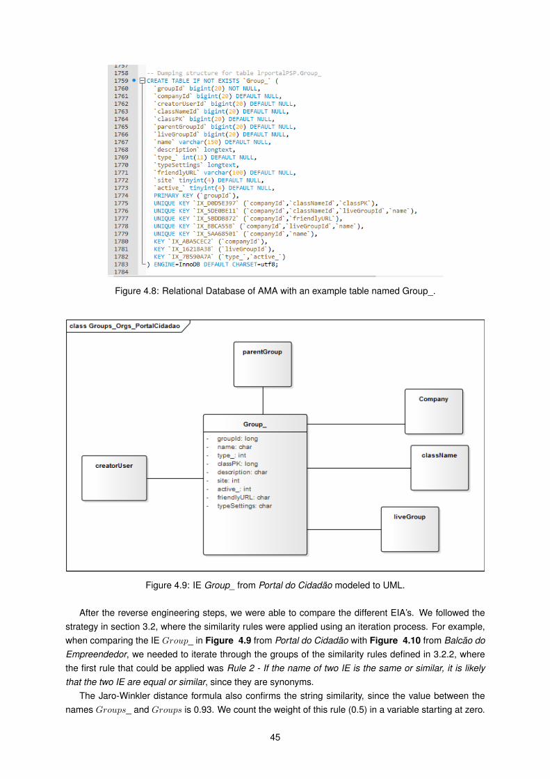
Figure 4.8: Relational Database of AMA with an example table named Group_.
Figure 4.9: IE Group_ from Portal do Cidadão modeled to UML.
After the reverse engineering steps, we were able to compare the different EIA’s. We followed thestrategy in section 3.2, where the similarity rules were applied using an iteration process. For example,when comparing the IE Group_ in Figure 4.9 from Portal do Cidadão with Figure 4.10 from Balcão doEmpreendedor, we needed to iterate through the groups of the similarity rules defined in 3.2.2, wherethe first rule that could be applied was Rule 2 - If the name of two IE is the same or similar, it is likelythat the two IE are equal or similar, since they are synonyms.
The Jaro-Winkler distance formula also confirms the string similarity, since the value between thenames Groups_ and Groups is 0.93. We count the weight of this rule (0.5) in a variable starting at zero.
45
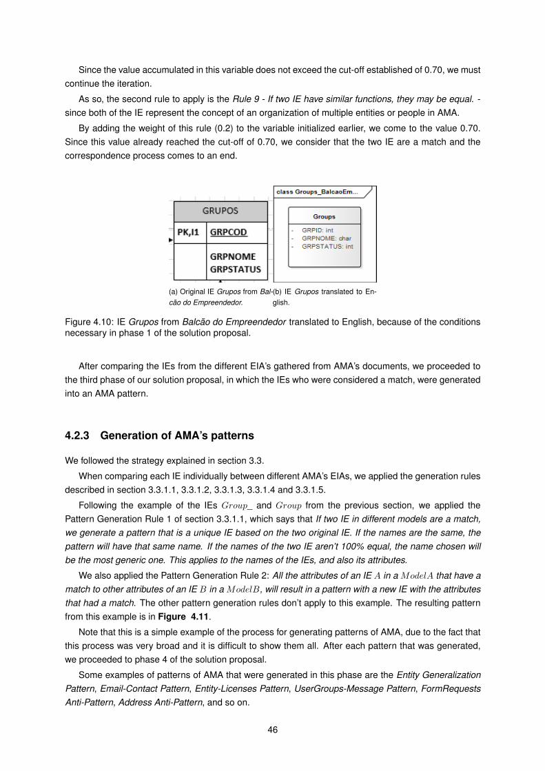
Since the value accumulated in this variable does not exceed the cut-off established of 0.70, we mustcontinue the iteration.
As so, the second rule to apply is the Rule 9 - If two IE have similar functions, they may be equal. -since both of the IE represent the concept of an organization of multiple entities or people in AMA.
By adding the weight of this rule (0.2) to the variable initialized earlier, we come to the value 0.70.Since this value already reached the cut-off of 0.70, we consider that the two IE are a match and thecorrespondence process comes to an end.
(a) Original IE Grupos from Bal-cão do Empreendedor.
(b) IE Grupos translated to En-glish.
Figure 4.10: IE Grupos from Balcão do Empreendedor translated to English, because of the conditionsnecessary in phase 1 of the solution proposal.
After comparing the IEs from the different EIA’s gathered from AMA’s documents, we proceeded tothe third phase of our solution proposal, in which the IEs who were considered a match, were generatedinto an AMA pattern.
4.2.3 Generation of AMA’s patterns
We followed the strategy explained in section 3.3.
When comparing each IE individually between different AMA’s EIAs, we applied the generation rulesdescribed in section 3.3.1.1, 3.3.1.2, 3.3.1.3, 3.3.1.4 and 3.3.1.5.
Following the example of the IEs Group_ and Group from the previous section, we applied thePattern Generation Rule 1 of section 3.3.1.1, which says that If two IE in different models are a match,we generate a pattern that is a unique IE based on the two original IE. If the names are the same, thepattern will have that same name. If the names of the two IE aren’t 100% equal, the name chosen willbe the most generic one. This applies to the names of the IEs, and also its attributes.
We also applied the Pattern Generation Rule 2: All the attributes of an IE A in a ModelA that have amatch to other attributes of an IE B in a ModelB, will result in a pattern with a new IE with the attributesthat had a match. The other pattern generation rules don’t apply to this example. The resulting patternfrom this example is in Figure 4.11.
Note that this is a simple example of the process for generating patterns of AMA, due to the fact thatthis process was very broad and it is difficult to show them all. After each pattern that was generated,we proceeded to phase 4 of the solution proposal.
Some examples of patterns of AMA that were generated in this phase are the Entity GeneralizationPattern, Email-Contact Pattern, Entity-Licenses Pattern, UserGroups-Message Pattern, FormRequestsAnti-Pattern, Address Anti-Pattern, and so on.
46
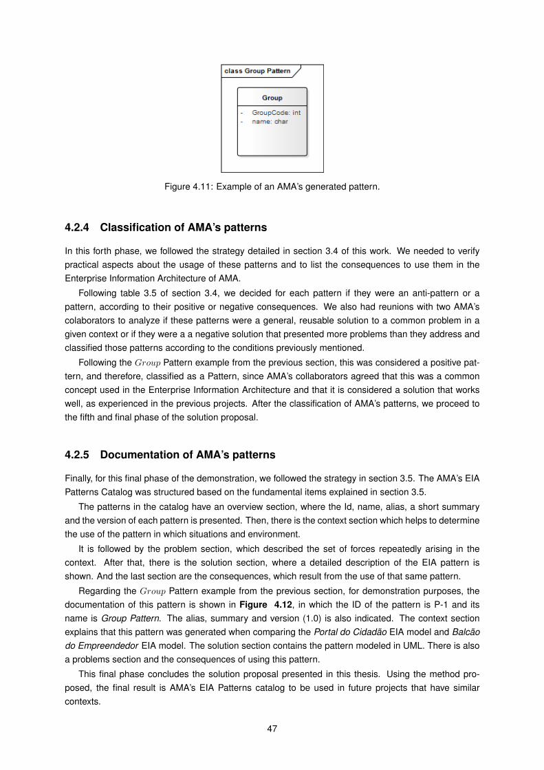
Figure 4.11: Example of an AMA’s generated pattern.
4.2.4 Classification of AMA’s patterns
In this forth phase, we followed the strategy detailed in section 3.4 of this work. We needed to verifypractical aspects about the usage of these patterns and to list the consequences to use them in theEnterprise Information Architecture of AMA.
Following table 3.5 of section 3.4, we decided for each pattern if they were an anti-pattern or apattern, according to their positive or negative consequences. We also had reunions with two AMA’scolaborators to analyze if these patterns were a general, reusable solution to a common problem in agiven context or if they were a a negative solution that presented more problems than they address andclassified those patterns according to the conditions previously mentioned.
Following the Group Pattern example from the previous section, this was considered a positive pat-tern, and therefore, classified as a Pattern, since AMA’s collaborators agreed that this was a commonconcept used in the Enterprise Information Architecture and that it is considered a solution that workswell, as experienced in the previous projects. After the classification of AMA’s patterns, we proceed tothe fifth and final phase of the solution proposal.
4.2.5 Documentation of AMA’s patterns
Finally, for this final phase of the demonstration, we followed the strategy in section 3.5. The AMA’s EIAPatterns Catalog was structured based on the fundamental items explained in section 3.5.
The patterns in the catalog have an overview section, where the Id, name, alias, a short summaryand the version of each pattern is presented. Then, there is the context section which helps to determinethe use of the pattern in which situations and environment.
It is followed by the problem section, which described the set of forces repeatedly arising in thecontext. After that, there is the solution section, where a detailed description of the EIA pattern isshown. And the last section are the consequences, which result from the use of that same pattern.
Regarding the Group Pattern example from the previous section, for demonstration purposes, thedocumentation of this pattern is shown in Figure 4.12, in which the ID of the pattern is P-1 and itsname is Group Pattern. The alias, summary and version (1.0) is also indicated. The context sectionexplains that this pattern was generated when comparing the Portal do Cidadão EIA model and Balcãodo Empreendedor EIA model. The solution section contains the pattern modeled in UML. There is alsoa problems section and the consequences of using this pattern.
This final phase concludes the solution proposal presented in this thesis. Using the method pro-posed, the final result is AMA’s EIA Patterns catalog to be used in future projects that have similarcontexts.
47
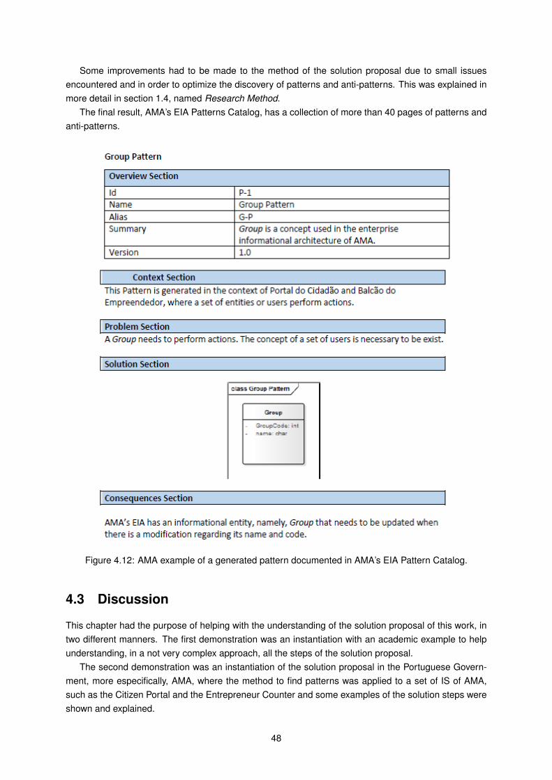
Some improvements had to be made to the method of the solution proposal due to small issuesencountered and in order to optimize the discovery of patterns and anti-patterns. This was explained inmore detail in section 1.4, named Research Method.
The final result, AMA’s EIA Patterns Catalog, has a collection of more than 40 pages of patterns andanti-patterns.
Figure 4.12: AMA example of a generated pattern documented in AMA’s EIA Pattern Catalog.
4.3 Discussion
This chapter had the purpose of helping with the understanding of the solution proposal of this work, intwo different manners. The first demonstration was an instantiation with an academic example to helpunderstanding, in a not very complex approach, all the steps of the solution proposal.
The second demonstration was an instantiation of the solution proposal in the Portuguese Govern-ment, more especifically, AMA, where the method to find patterns was applied to a set of IS of AMA,such as the Citizen Portal and the Entrepreneur Counter and some examples of the solution steps wereshown and explained.
48
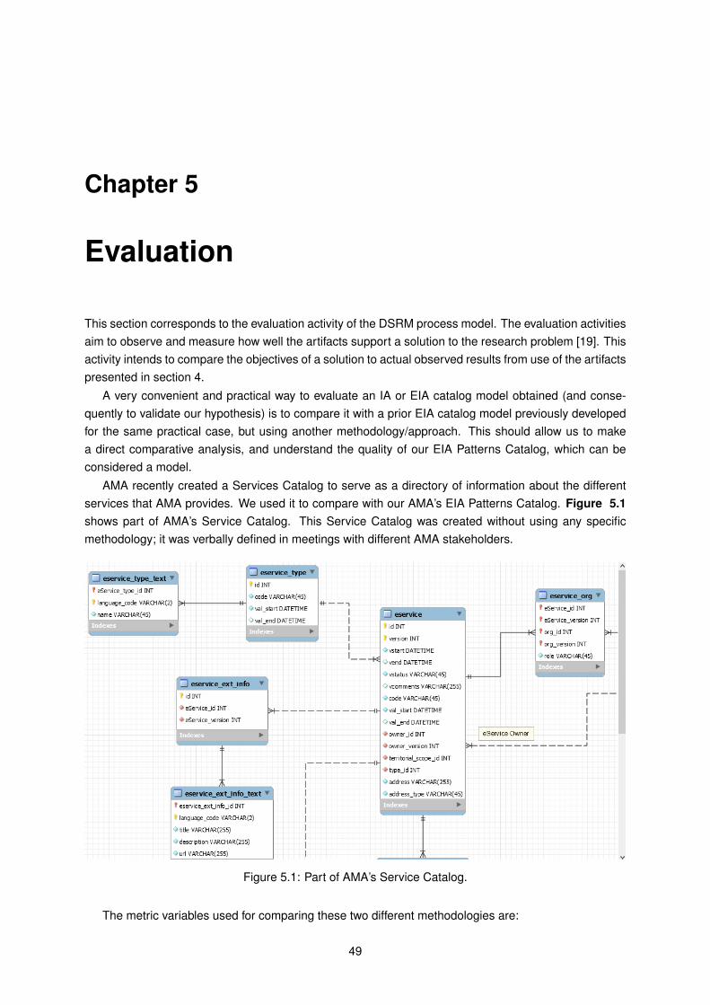
Chapter 5
Evaluation
This section corresponds to the evaluation activity of the DSRM process model. The evaluation activitiesaim to observe and measure how well the artifacts support a solution to the research problem [19]. Thisactivity intends to compare the objectives of a solution to actual observed results from use of the artifactspresented in section 4.
A very convenient and practical way to evaluate an IA or EIA catalog model obtained (and conse-quently to validate our hypothesis) is to compare it with a prior EIA catalog model previously developedfor the same practical case, but using another methodology/approach. This should allow us to makea direct comparative analysis, and understand the quality of our EIA Patterns Catalog, which can beconsidered a model.
AMA recently created a Services Catalog to serve as a directory of information about the differentservices that AMA provides. We used it to compare with our AMA’s EIA Patterns Catalog. Figure 5.1shows part of AMA’s Service Catalog. This Service Catalog was created without using any specificmethodology; it was verbally defined in meetings with different AMA stakeholders.
Figure 5.1: Part of AMA’s Service Catalog.
The metric variables used for comparing these two different methodologies are:
49
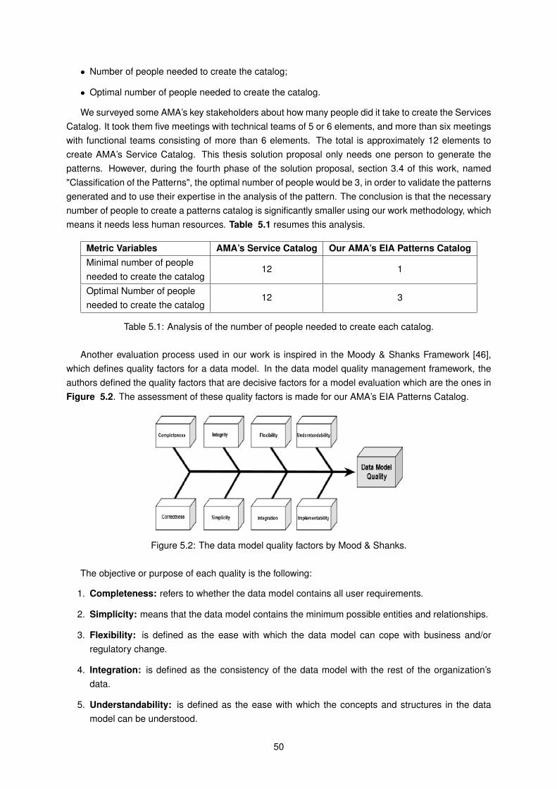
• Number of people needed to create the catalog;
• Optimal number of people needed to create the catalog.
We surveyed some AMA’s key stakeholders about how many people did it take to create the ServicesCatalog. It took them five meetings with technical teams of 5 or 6 elements, and more than six meetingswith functional teams consisting of more than 6 elements. The total is approximately 12 elements tocreate AMA’s Service Catalog. This thesis solution proposal only needs one person to generate thepatterns. However, during the fourth phase of the solution proposal, section 3.4 of this work, named"Classification of the Patterns", the optimal number of people would be 3, in order to validate the patternsgenerated and to use their expertise in the analysis of the pattern. The conclusion is that the necessarynumber of people to create a patterns catalog is significantly smaller using our work methodology, whichmeans it needs less human resources. Table 5.1 resumes this analysis.
Metric Variables AMA’s Service Catalog Our AMA’s EIA Patterns CatalogMinimal number of peopleneeded to create the catalog
12 1
Optimal Number of peopleneeded to create the catalog
12 3
Table 5.1: Analysis of the number of people needed to create each catalog.
Another evaluation process used in our work is inspired in the Moody & Shanks Framework [46],which defines quality factors for a data model. In the data model quality management framework, theauthors defined the quality factors that are decisive factors for a model evaluation which are the ones inFigure 5.2. The assessment of these quality factors is made for our AMA’s EIA Patterns Catalog.
Figure 5.2: The data model quality factors by Mood & Shanks.
The objective or purpose of each quality is the following:
1. Completeness: refers to whether the data model contains all user requirements.
2. Simplicity: means that the data model contains the minimum possible entities and relationships.
3. Flexibility: is defined as the ease with which the data model can cope with business and/orregulatory change.
4. Integration: is defined as the consistency of the data model with the rest of the organization’sdata.
5. Understandability: is defined as the ease with which the concepts and structures in the datamodel can be understood.
50
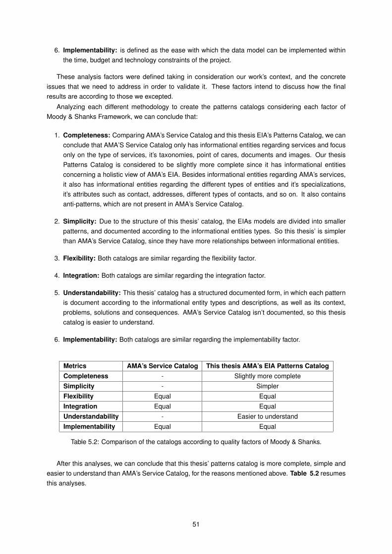
6. Implementability: is defined as the ease with which the data model can be implemented withinthe time, budget and technology constraints of the project.
These analysis factors were defined taking in consideration our work’s context, and the concreteissues that we need to address in order to validate it. These factors intend to discuss how the finalresults are according to those we excepted.
Analyzing each different methodology to create the patterns catalogs considering each factor ofMoody & Shanks Framework, we can conclude that:
1. Completeness: Comparing AMA’s Service Catalog and this thesis EIA’s Patterns Catalog, we canconclude that AMA’S Service Catalog only has informational entities regarding services and focusonly on the type of services, it’s taxonomies, point of cares, documents and images. Our thesisPatterns Catalog is considered to be slightly more complete since it has informational entitiesconcerning a holistic view of AMA’s EIA. Besides informational entities regarding AMA’s services,it also has informational entities regarding the different types of entities and it’s specializations,it’s attributes such as contact, addresses, different types of contacts, and so on. It also containsanti-patterns, which are not present in AMA’s Service Catalog.
2. Simplicity: Due to the structure of this thesis’ catalog, the EIAs models are divided into smallerpatterns, and documented according to the informational entities types. So this thesis’ is simplerthan AMA’s Service Catalog, since they have more relationships between informational entities.
3. Flexibility: Both catalogs are similar regarding the flexibility factor.
4. Integration: Both catalogs are similar regarding the integration factor.
5. Understandability: This thesis’ catalog has a structured documented form, in which each patternis document according to the informational entity types and descriptions, as well as its context,problems, solutions and consequences. AMA’s Service Catalog isn’t documented, so this thesiscatalog is easier to understand.
6. Implementability: Both catalogs are similar regarding the implementability factor.
Metrics AMA’s Service Catalog This thesis AMA’s EIA Patterns CatalogCompleteness - Slightly more completeSimplicity - SimplerFlexibility Equal EqualIntegration Equal EqualUnderstandability - Easier to understandImplementability Equal Equal
Table 5.2: Comparison of the catalogs according to quality factors of Moody & Shanks.
After this analyses, we can conclude that this thesis’ patterns catalog is more complete, simple andeasier to understand than AMA’s Service Catalog, for the reasons mentioned above. Table 5.2 resumesthis analyses.
51
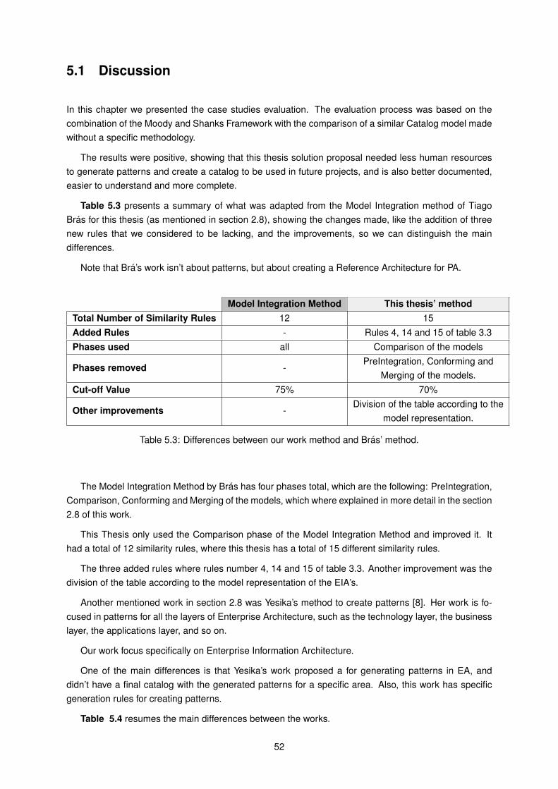
5.1 Discussion
In this chapter we presented the case studies evaluation. The evaluation process was based on thecombination of the Moody and Shanks Framework with the comparison of a similar Catalog model madewithout a specific methodology.
The results were positive, showing that this thesis solution proposal needed less human resourcesto generate patterns and create a catalog to be used in future projects, and is also better documented,easier to understand and more complete.
Table 5.3 presents a summary of what was adapted from the Model Integration method of TiagoBrás for this thesis (as mentioned in section 2.8), showing the changes made, like the addition of threenew rules that we considered to be lacking, and the improvements, so we can distinguish the maindifferences.
Note that Brá’s work isn’t about patterns, but about creating a Reference Architecture for PA.
Model Integration Method This thesis’ methodTotal Number of Similarity Rules 12 15Added Rules - Rules 4, 14 and 15 of table 3.3Phases used all Comparison of the models
Phases removed -PreIntegration, Conforming and
Merging of the models.Cut-off Value 75% 70%
Other improvements -Division of the table according to the
model representation.
Table 5.3: Differences between our work method and Brás’ method.
The Model Integration Method by Brás has four phases total, which are the following: PreIntegration,Comparison, Conforming and Merging of the models, which where explained in more detail in the section2.8 of this work.
This Thesis only used the Comparison phase of the Model Integration Method and improved it. Ithad a total of 12 similarity rules, where this thesis has a total of 15 different similarity rules.
The three added rules where rules number 4, 14 and 15 of table 3.3. Another improvement was thedivision of the table according to the model representation of the EIA’s.
Another mentioned work in section 2.8 was Yesika’s method to create patterns [8]. Her work is fo-cused in patterns for all the layers of Enterprise Architecture, such as the technology layer, the businesslayer, the applications layer, and so on.
Our work focus specifically on Enterprise Information Architecture.
One of the main differences is that Yesika’s work proposed a for generating patterns in EA, anddidn’t have a final catalog with the generated patterns for a specific area. Also, this work has specificgeneration rules for creating patterns.
Table 5.4 resumes the main differences between the works.
52
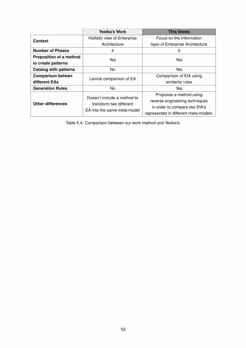
Yesika’s Work This thesis
ContextHollistic view of Enterprise
ArchitectureFocus on the Information
layer of Enterprise ArchitectureNumber of Phases 4 5Proposition of a methodto create patterns
Yes Yes
Catalog with patterns No YesComparison betwendifferent EAs
Lexical comparison of EAComparison of EIA using
similarity rulesGeneration Rules No Yes
Other differencesDoesn’t include a method to
transform two differentEA into the same meta-model
Proposes a method usingreverse engineering techniquesin order to compare two EIA’s
represented in different meta-models.
Table 5.4: Comparison between our work method and Yesika’s.
53
Chapter 6
Conclusion
6.1 Results Achieved
We believe that the solution proposal described in this work adds value to it’s surrounding context: thedevelopment of a method to generate EIA patterns and the creation of a catalog with those patterns, forthe Portuguese Public Administration.
The main contributions of this work are directly related to the main questions in the section 1.2 of thiswork and to the objectives in section 3. As such, it is important to relate these two components.
• To the main question "Is it possible to create a catalog of Information Architectures patterns to beused by the Portuguese PA, specifically AMA?" is related with the objective Creation of a AMA’sEIA Patterns Catalog and implement solutions to this specific industry based on historical dataanalyzed and information necessary for optimized architecture design decisions;.
• The question "How do we compare different Enterprise Information Architectures?" is related withthe following objectives: Identification of correspondences between IE of different information ar-chitectures and identification of IE attributes between different Enterprise Information Architecturesfrom AMA;
• The question "How can we extract patterns and anti-patterns?" has a correspondence with thefollowing objective: development of a method to create an Enterprise Information Architecture Pat-terns and Anti-Patterns Catalog as a categorization of recurring issues and its proposed solutions.
• The question "How do we document Enterprise Information Architecture patterns and anti-patterns?"is related with the objective Creation of a AMA’s EIA Patterns Catalog.
We describe next the way each of the defined objectives were accomplished, by giving, at the sametime, the answer to the questions matched with them:
• Development of a method to create an Enterprise Information Architecture Patterns andAnti-Patterns Catalog as a categorization of recurring issues and its proposed solutions:The 5-phased method proposed in chapter 3 allows us to create an EIA Patterns Catalog withthe generated patterns, in which the first phase of the solution is to gather EIA documents thathave similar contexts, problems, and are in the same meta-model and language. The secondphase is to make binary comparisons of the EIA, in which given two models with similar context,we calculate the similarities between any pair of IE. We Iterate, in order, for all the similarity rulegroups and apply one rule of each group. To each similarity rule, it is assigned a weight between
54
0 and 1. When sum of weights is higher than the cut-off (0.70) or equal, the IEs are considereda match and the process ends. In the third phase, if two IE are similar, generation pattern rulesexplained in section 3.4 should be iterated and applied when the conditions are verified. In theforth phase, we classify patterns and anti-patterns. Finally, in the fifth phase, we document thosepatterns according to a defined structure. Evaluation in section 5 shows that this method requiresless human resources, with the minimum been 1 (while AMA’s Service Catalog made without aspecific methodology required 12 human resources) and it is better documented. The final resultwas an EIA Patterns Catalog for AMA;
• Identification of correspondences between IE of different information architectures andIdentification of IE attributes between different Enterprise Information Architectures fromAMA: With the second phase of the solution proposal, in section 3.2, named Comparison of theEIA, these objectives were accomplished with the matching process that was defined using a totalof 15 similarity rules (8 regarding structure and extension similarity between IEs, 4 about inter-nal structure, 2 about assured equality and 1 regarding terminological similarity) to compare thedifferent informational entities and its attributes and relationships;
• Identify common problems in this specific industry concerning Enterprise Information Ar-chitecture and extract the patterns: This objective has also been accomplished, with the thirdphase of our solution proposal, in section 3.3, which has 5 generation rules, in which we define, forexample, that the pattern will have the same name, attributes, relationships that were considereda match between the IEs during the comparison phase, and with the forth phase, in section 3.4,where we propose a method to extract the patterns and classify them as a pattern if they havepositive consequences or anti-pattern, if it’s a bad a solution;
• Implement solutions to this specific industry based on historical data analyzed and infor-mation necessary for optimized architecture design decisions: It has been possible to achievethis objective with the final artifact of this research, which is the AMA’s EIA Patterns Catalog, whichhas a total of 41 patterns, including 3 anti-patterns, and where each pattern is documented accord-ing to their name, type, context, problem to solve, consequences, among other optional sections;
• Reduce the costs for creating a Patterns Catalog, by reducing the number of human re-sources necessary to develop it: This final objective has also been achieved, where the chapter5 of our paper concluded that our methodology only needs, at minimum, 1 person to develop a Pat-terns Catalog, while the current Service’s Catalog of AMA created without a specific methodology,needed 12 people. Our EIA Patterns Catalog also serves as a guideline to avoid common mistakesin future projects of AMA (with similar contexts), by not using the anti-patterns documented in thecatalog.
6.2 Communication
This section corresponds to activity 6 of DSRM methodology - Communication.Considering this investigation’s scope, a paper has been accepted and presented in 8o INForum
- Simpósio de Informática, realized in Instituto Superior Técnico, Universidade de Lisboa, in Septem-ber 9th, 2016, in Lisbon, where this work’s solution proposal regarding comparing different EnterpriseInformation Architectures and extracting patterns was addressed [17].
Furthermore, this document contributes to the communication of the investigation that has beenmade, since it presents, to the scientific community, a new study component for work to be developed inthe future.
55
6.3 Lessons Learned and Final Thoughts
Patterns have become accepted in many different areas and described as very useful because theyreuse knowledge already acquired from experienced users and they capture and document provenpractices. The importance of information in the Portuguese PA and Government, the lack of specificmethodologies for improving and developing the Enterprise Information Architectures and the nonexis-tence of a methodology for creating an EIA patterns catalog in the Portuguese Public Administrationregarding future projects with similar context, lead us to need for the Portuguese Public Administrationto have a catalog of EIA patterns to be used as the basis for future projects that have akin context withformer PA projects.
A solution presented is the development of a method to create patterns and anti-patterns for Enter-prise Information Architecture and the creation of a catalog to be used by the Portuguese Government,more especifically AMA, since patterns are a way to document proven practice solutions for recurringproblems in a given context and proved to be a valuable approach for documenting knowledge.
Chapter 1 defined and described the Design Science Research Methodology that was applied on tosupport our work on scientific basis, and therefore guarantee its validity and continuity. We also clarifiedthe problem and established the motivation towards the solution. The fundamental concepts and relatedwork were explained on chapter 2.
The solution objective’s, mentioned above, and solution architecture were described in chapter 3,where the Model Integration method developed by Brás [20] was adapted. We explained that our processhas five phases: gathering of the EIA documents (where we analyze and select IAs with similar meta-model and context), comparison of the EIA (we use an iteration process with 15 rules of similarity, withdifferent weights, to conclude if each pair of IE is correspondent or not), generation of the pattern (weuse 5 rules to generate the pattern and classify it as a pattern or anti-pattern), classification as a patternor anti-pattern, and finally, the documentation of the pattern, where we write our pattern form for ourAMA’s EIA Patterns Catalog.
On chapter 5, a demonstration was performed. An academic example was used and the process ofcreating AMA’s EIA patterns catalog was explained.
Finally, on chapter 6 we showed how this work was evaluated, by using assessed criteria to makea comparison with other service catalog by AMA. In Appendix A, we present AMA’s Information Archi-tecture. Appendix B contains the Liferay Database that was used in Portal do Cidadão’s database, andappendix C contains the final result: AMA’s EIA Patterns Catalog.
By using the knowledge gathered under the thesis development, and by applying it into the develop-ment of the work during various iterations, we propose a methodology for generating EIA patterns forthe Portuguese Government, that will serve as a guide for the PA in order to achieve a consistent andoptimized Enterprise Information Architecture in future projects with similar context.
6.4 Limitations
Along with the contributions that our work was able to give, we also need to stress its limitations. Theselimitations are related both to decisions that we have taken during our work, and also due to the timelimitations associated with this thesis.
One of the limitations is the lack of adequate comparative term for the final results. Since EnterpriseInformation Architecture patterns are practically nonexistent in multiple areas, it’s difficult to chose theright metrics and compare our method and our final catalog with already existing methods to createpatterns for Enterprise Architectures.
56
Another limitation is that this method is not automated. This is due to the fact that the EnterpriseInformation Architectures are usually represented in relational databases models or in higher abstractionlevel models, such as UML or EA model, which is difficult to make a automated comparison betweenthem since they are in different meta-models. Initially, this thesis’ solution proposal was to automatethe pattern generation process for EIAs represented in ArchiMate Model, with the help of the ArchiModelling tool who has the functionality of exporting architectures to XML. However, the PortuguesePA, more specifically, AMA, the agency we worked with, didn’t have any of their EIAs represented inArchiMate model, so it wasn’t possible to do it, and our solution proposal was adapted.
6.5 Future Work
Firstly, we think that our proposal has potential, in order to be considered a good methodology to developEnterprise Information Architecture patterns. However, we believe that this methodology can still beimproved.
There is still plenty of research that can be done having this thesis as a basis.Based on the outcomes of this work, we may point some following opportunities for related future
work, such as applying it to more study cases. We believe that the application of this methodology tomore cases where is possible to compare the results with defined Enterprise Information Architecturesis quite relevant. This could improve the feedback received from such a comparative analysis, and woulddefinitely improve the quality of the methodology as well as extend it.
This, it is important to conduct further DSRM work, integrating more aspects to compare differentEnterprise Information Architectures.
It is also possible to extend the scope and/or depth of the thesis work, e.g. by developing solution’sproposal that addresses the inconsistencies detected and by eemonstrating and evaluating the methodin more government owned companies.
Another relevant improvement is to automate the process of our solution proposal.In short, as enterprises become increasingly information based, making improvements in their in-
formation activities is a top priority to assure their continuing competitiveness and a key to achievingthese improvements is developing an Enterprise Information Architecture. Therefore, this research workcan help creating value by capturing patterns that can be useful in future projects with similar context,regarding the Portuguese Government and PA.
57
References
[1] Godinez, M., Hechler, E., Koenig, K., Lockwood, S., Oberhofer, M. and Schroeck, M., The Art ofEnterprise Information Architecture: A Systems-Bases Approach for Unlocking Business Insight.IBM Press, 1993.
[2] Watson, R. W., “An Enterprise Information Architecture: A Case Study for Decentralized Organiza-tions,” IEEE Computer Society, 2000.
[3] Martin, A., Dmitriev, D. and Akeroyd, J., “A resurgence of interest in Information Architecture,”International Journal of Information Management, vol. 30, pp. 6–12, 2010.
[4] Zhang, C. and Budgen, D., “What do we know about the effectiveness of software design patterns?,”IEEE transactions on software engineering, vol. 38, no. 5, pp. 1213 – 1231, 2012.
[5] Buschmann, F., Meunier, R., Rohnert, H., Sommerlad, P. and Stal, M., Pattern-Oriented SoftwareArchitecture Volume 1: A System of Patterns. Wiley, 2001.
[6] Harrison, N., Avgeriou, P. and Zdun, U., “Using Patterns to Capture Architectural Decisions,” IEEEComputer Society, vol. 24, no. 4, 2007.
[7] Fowler, M., Patterns of Enterprise Application Architecture. Addison-Wesley, 2002.
[8] Reinolds, Y., “PATETA: PATterns for EnTerprise reference Architectures,” Master’s thesis, InstitutoSuperior Técnico, Universidade de Lisboa, 2015.
[9] Hicks, B., “Lean information management: Understanding and eliminating waste,” InternationalJournal of Information Management: The Journal for Information Professionals, vol. 27, no. 4,pp. 233–249, 2007.
[10] Chaffey, D. and Wood, S., Business information management, improving performance using infor-mation systems. Addison-Wesley, 2004.
[11] Saiz, J., Rodriguez, R., Bas, A. and Verdecho, M., “An information architecture for a performancemanagement framework by collaborating SMEs,” Computers in Industry, vol. 61, no. 7, p. 676–685,2010.
[12] Ernst, A., “A Pattern-based Approach to Enterprise Architecture Management,” Master’s thesis,Fakultät für Informatik der Technischen Universität München, 2010.
[13] Gomes, B., “Information Architecture and Enterprise Ontologies,” Master’s thesis, Instituto SuperiorTécnico, Universidade de Lisboa, 2011.
[14] Fowler, M., Analysis Patterns: Reusable Object Models. Addison-Wesley Professional, 1 ed., 1996.
58
[15] Agência para a Modernização Administrativa, “Interoperabilidade na Administração Pública. Pro-cedimentos para a adesão à iAP - Plataforma de Interoperabilidade da Administração Pública,” (inportuguese), 2011.
[16] ISO 9126, Information Technology - Software Product Evaluation - Software Quality Characteristicsand Metrics. International Organization for Standardization, 2001.
[17] Lemos, R. and Vasconcelos, A., “Enterprise Information Patterns for Government,” in 8o INForum -Simpósio Nacional de Informática, Instituto Superior Técnico, Universidade de Lisboa, 2016.
[18] Hevner, A.R., March, S.T., Park, J. and Ram, S., “Design Science in Information Systems Re-search,” MIS Quarterly, vol. 28, no. 1, pp. 75–105, 2004.
[19] Peffers, K., Tuunanen, T., Rothenberger, M. and Chatterjee, S., “A design science research method-ology for information systems research,” Journal of Management Information Systems, vol. 24,no. 3, pp. 45–78, 2008.
[20] Brás, T., “Arquitetura Informacional de Referência para o Setor da Saúde Portuguesa,” Master’sthesis, Instituto Superior Técnico, Universidade de Lisboa, 2015.
[21] Aier, S., Riege, C. and Winter, R., “Unternehmensarchitektur - Literaturüberblick und Stand derPraxis,” Wirtschaftsinformatik, vol. 50, no. 4, pp. 292–304, 2008.
[22] Zachman, J., “A Framework for Information Systems Architecture,” IBM Systems Journal, vol. 26,no. 3, p. 276, 1987.
[23] Brancheau, J. and Wetherbe, J., “Information architectures: Methods and practice, InformationProcessing and Management,” Journal Information Processing and Management: an InternationalJournal, vol. 22, no. 6, pp. 453 – 463, 1986.
[24] Allen, B. and Boynton, A., “Information architecture: In search of efficient flexibility,” MIS Quarterly,vol. 15, no. 4, pp. 435–445, 1991.
[25] Vasconcelos, A., “Arquitecturas de Sistemas de Informação no Contexto do Negócio,” Master’sthesis, Instituto Superior Técnico, Universidade de Lisboa, 2001.
[26] Inmon, W., Data Architecture: The Information Paradigm. Wellesley, MA, USA: QED InformationSciences, 2 ed., 1989.
[27] Vasconcelos, A., Caetano, A., Neves, J., Sinogas, P., Mendes, R. and Tribolet, J., “A frameworkfor modeling strategy, business processes and information systems,” Enterprise Distributed ObjectComputing Conference, 2001.
[28] Fowler, M., UML Distilled: A Brief Guide to the Standard Object Modeling Language. Addison-Wesley, 2 ed., 2003.
[29] Halpin, T., Information Modeling and Relational Databases: From Conceptual Analysis to LogicalDesign. San Diego: Morgan Kaufmann, 1 ed., 2001.
[30] The Object Management Group, “Introduction To OMG’s Unified Modeling Language,” 2015.
[31] Chen, P., “The entity-relationship model—toward a unified view of data,” ACM Transactions onDatabase Systems (TODS), vol. 1, no. 1, pp. 9–36, 1976.
[32] Barker, R., CASE Method: Entity Relationship Modelling. Addison-Wesley Professional, 1990.
59
[33] Adelsberger, H. and Körner, F., “Data modeling with IDEF1X,” in Information Management in Com-puter Integrated Manufacturing, pp. 355–391, Springer, 2005.
[34] Alexander, C., Ishikawa, S. and Silverstein, M., A Pattern Language: Towns, Buildings, Construc-tion. USA: Oxford University Press, 1977.
[35] Buschmann, F., Henney, K. and Schmidt, D., Pattern- Oriented Software Architecture Volume 4: APattern Language for Distributed Computing. Wiley, 2007.
[36] Douglass, B., Real-Time Design Patterns: Robust Scalable Architecture for Real-Time Systems.Addison-Wesley Professional, 2002.
[37] Brown, W., Malveau, R., McCormick, H. and Mowbray, T., AntiPatterns: refactoring software, archi-tectures, and projects in crisis. New York, NY, USA: Wiley & Sons, 1998.
[38] Chikofsky, E.J. and Cross, J.H., “Reverse engineering and design recovery: a taxonomy,” IEEESoftware, vol. 7, no. 1, pp. 13–17, 1990.
[39] Bagui, S. and Earp, R., Database Design Using Entity-Relationship Diagrams, Second Edition.Auerbach Publications , 2011.
[40] Batini, C., Lenzerini, M. and Navathe, S. B., “A comparative analysis of methodologies for databaseschema integration,” Journal ACM Computing Surveys (CSUR), vol. 18, no. 4, pp. 323–364, 1986.
[41] Sheth, P., “Changing Focus on Interoperability in Information Systems: From System, Syntax,Structure to Semantics,” in Interoperating Geographic Information Systems, pp. 5–29, SpringerUS, 1999.
[42] Ehrig, M. and Sure, Y, “Ontology Mapping – An Integrated Approach,” in The Semantic Web: Re-search and Applications, pp. 76–91, Springer Berlin Heidelberg, 2004.
[43] Silva, L. and Silva, F., “Reconhecimento de Padrões Arquitecturais em Sistemas Legados Java,”tech. rep., Universidade da Tecnologia e do Trabalho, 2008.
[44] Gondima, F., “Algoritmo de comparação de strings para integração de esquemas de dados,” Mas-ter’s thesis, Universidade Federal de Pernambuco, 2006.
[45] Winkler, W. E., “String Comparator Metrics and Enhanced Decision Rules in the Fellegi-SunterModel of Record Linkage,” Proceedings of the Section on Survey Research, pp. 354–359, 1990.
[46] Moody, D. and Shanks, G., “Improving the quality of data models: empirical validation of a qualitymanagement framework,” Information Systems, vol. 28, no. 6, p. 619–650, 2003.
60
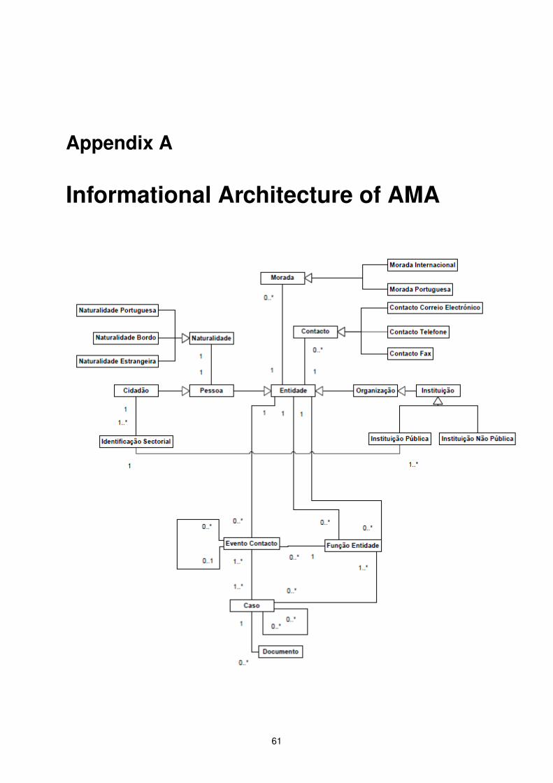
Appendix A
Informational Architecture of AMA
61
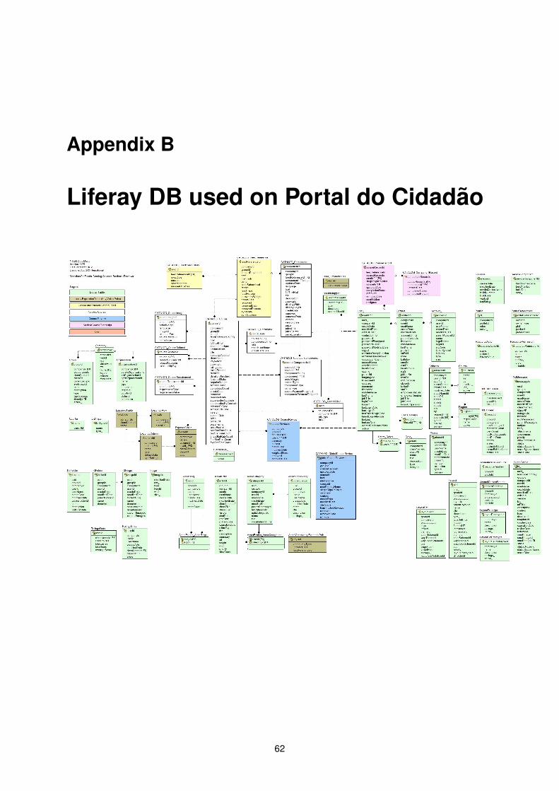
Appendix B
Liferay DB used on Portal do Cidadão
62

Appendix C
AMA’s EIA Patterns Catalog
63
1
Enterprise Information Architecture
Patterns Catalog for AMA
Release 1.0
October 2016
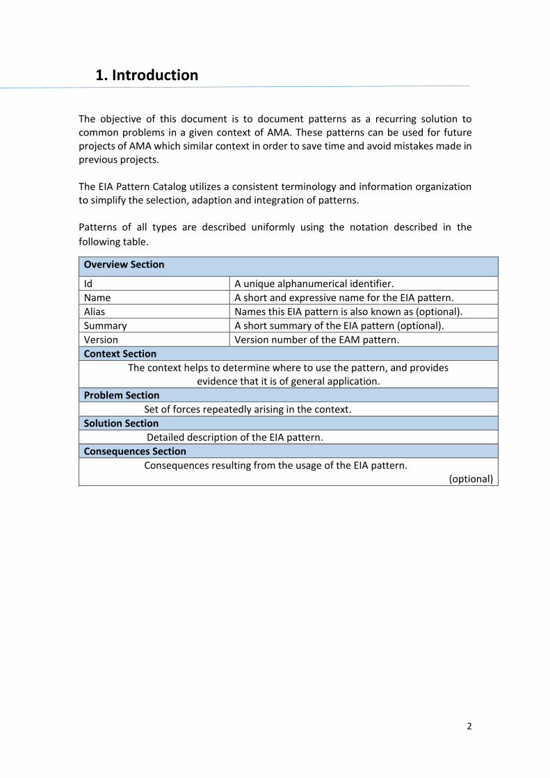
2
1. Introduction The objective of this document is to document patterns as a recurring solution to common problems in a given context of AMA. These patterns can be used for future projects of AMA which similar context in order to save time and avoid mistakes made in previous projects. The EIA Pattern Catalog utilizes a consistent terminology and information organization to simplify the selection, adaption and integration of patterns. Patterns of all types are described uniformly using the notation described in the
following table.
Overview Section
Id A unique alphanumerical identifier.
Name A short and expressive name for the EIA pattern.
Alias Names this EIA pattern is also known as (optional).
Summary A short summary of the EIA pattern (optional).
Version Version number of the EAM pattern.
Context Section
The context helps to determine where to use the pattern, and provides evidence that it is of general application.
Problem Section
Set of forces repeatedly arising in the context.
Solution Section
Detailed description of the EIA pattern.
Consequences Section
Consequences resulting from the usage of the EIA pattern. (optional)
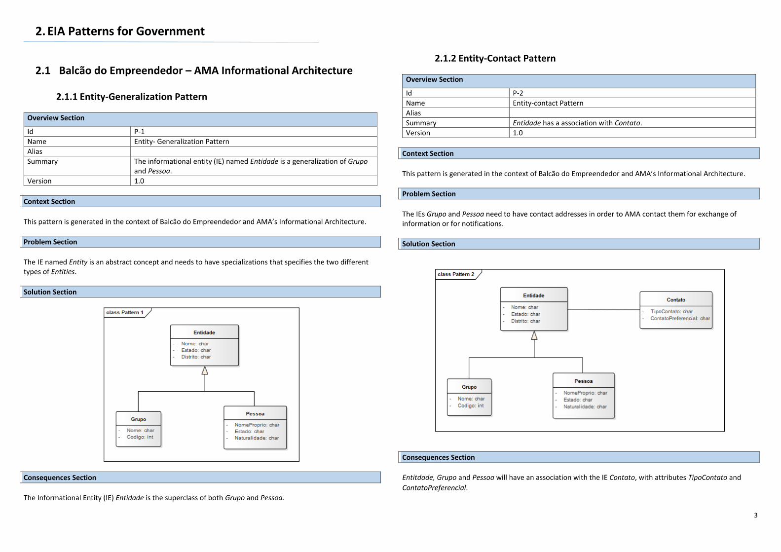
3
2. EIA Patterns for Government
2.1 Balcão do Empreendedor – AMA Informational Architecture
2.1.1 Entity-Generalization Pattern
Overview Section
Id P-1
Name Entity- Generalization Pattern
Alias
Summary The informational entity (IE) named Entidade is a generalization of Grupo and Pessoa.
Version 1.0
Context Section This pattern is generated in the context of Balcão do Empreendedor and AMA’s Informational Architecture.
Problem Section The IE named Entity is an abstract concept and needs to have specializations that specifies the two different types of Entities.
Solution Section
Consequences Section The Informational Entity (IE) Entidade is the superclass of both Grupo and Pessoa.
2.1.2 Entity-Contact Pattern
Overview Section
Id P-2
Name Entity-contact Pattern
Alias
Summary Entidade has a association with Contato.
Version 1.0
Context Section This pattern is generated in the context of Balcão do Empreendedor and AMA’s Informational Architecture.
Problem Section The IEs Grupo and Pessoa need to have contact addresses in order to AMA contact them for exchange of information or for notifications.
Solution Section
Consequences Section Entitdade, Grupo and Pessoa will have an association with the IE Contato, with attributes TipoContato and
ContatoPreferencial.
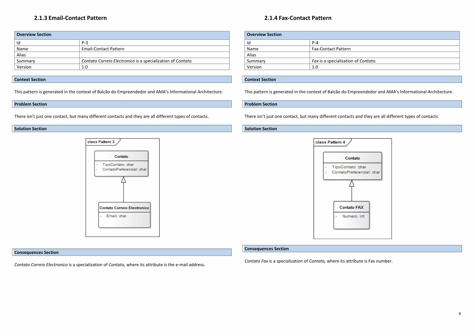
4
2.1.3 Email-Contact Pattern
Overview Section
Id P-3
Name Email-Contact Pattern
Alias
Summary Contato Correio Electronico is a specialization of Contato.
Version 1.0
Context Section This pattern is generated in the context of Balcão do Empreendedor and AMA’s Informational Architecture.
Problem Section There isn’t just one contact, but many different contacts and they are all different types of contacts.
Solution Section
Consequences Section Contato Correio Electronico is a specialization of Contato, where its attribute is the e-mail address.
2.1.4 Fax-Contact Pattern
Overview Section
Id P-4
Name Fax-Contact Pattern
Alias
Summary Fax is a specialization of Contato.
Version 1.0
Context Section This pattern is generated in the context of Balcão do Empreendedor and AMA’s Informational Architecture.
Problem Section There isn’t just one contact, but many different contacts and they are all different types of contacts.
Solution Section
Consequences Section Contato Fax is a specialization of Contato, where its attribute is Fax number.
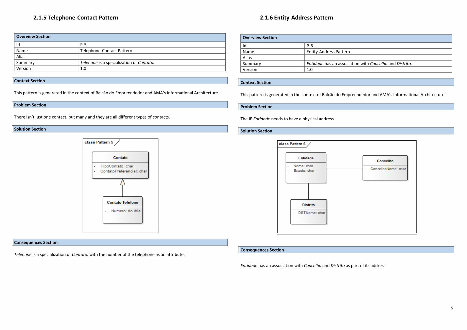
5
2.1.5 Telephone-Contact Pattern
Overview Section
Id P-5
Name Telephone-Contact Pattern
Alias
Summary Telehone is a specialization of Contato.
Version 1.0
Context Section This pattern is generated in the context of Balcão do Empreendedor and AMA’s Informational Architecture.
Problem Section There isn’t just one contact, but many and they are all different types of contacts.
Solution Section
Consequences Section
Telehone is a specialization of Contato, with the number of the telephone as an attribute.
2.1.6 Entity-Address Pattern
Overview Section
Id P-6
Name Entity-Address Pattern
Alias
Summary Entidade has an association with Concelho and Distrito.
Version 1.0
Context Section This pattern is generated in the context of Balcão do Empreendedor and AMA’s Informational Architecture.
Problem Section The IE Entidade needs to have a physical address.
Solution Section
Consequences Section
Entidade has an association with Concelho and Distrito as part of its address.
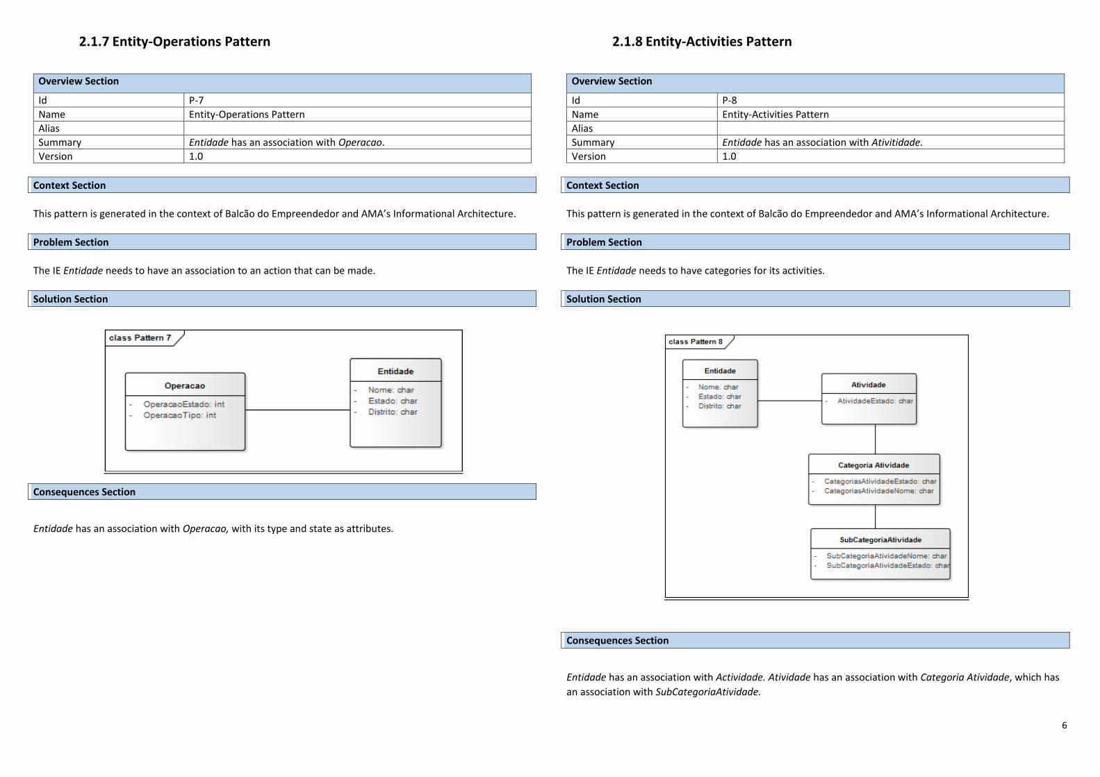
6
2.1.7 Entity-Operations Pattern
Overview Section
Id P-7
Name Entity-Operations Pattern
Alias
Summary Entidade has an association with Operacao.
Version 1.0
Context Section This pattern is generated in the context of Balcão do Empreendedor and AMA’s Informational Architecture.
Problem Section The IE Entidade needs to have an association to an action that can be made.
Solution Section
Consequences Section
Entidade has an association with Operacao, with its type and state as attributes.
2.1.8 Entity-Activities Pattern
Overview Section
Id P-8
Name Entity-Activities Pattern
Alias
Summary Entidade has an association with Ativitidade.
Version 1.0
Context Section This pattern is generated in the context of Balcão do Empreendedor and AMA’s Informational Architecture.
Problem Section The IE Entidade needs to have categories for its activities.
Solution Section
Consequences Section
Entidade has an association with Actividade. Atividade has an association with Categoria Atividade, which has
an association with SubCategoriaAtividade.
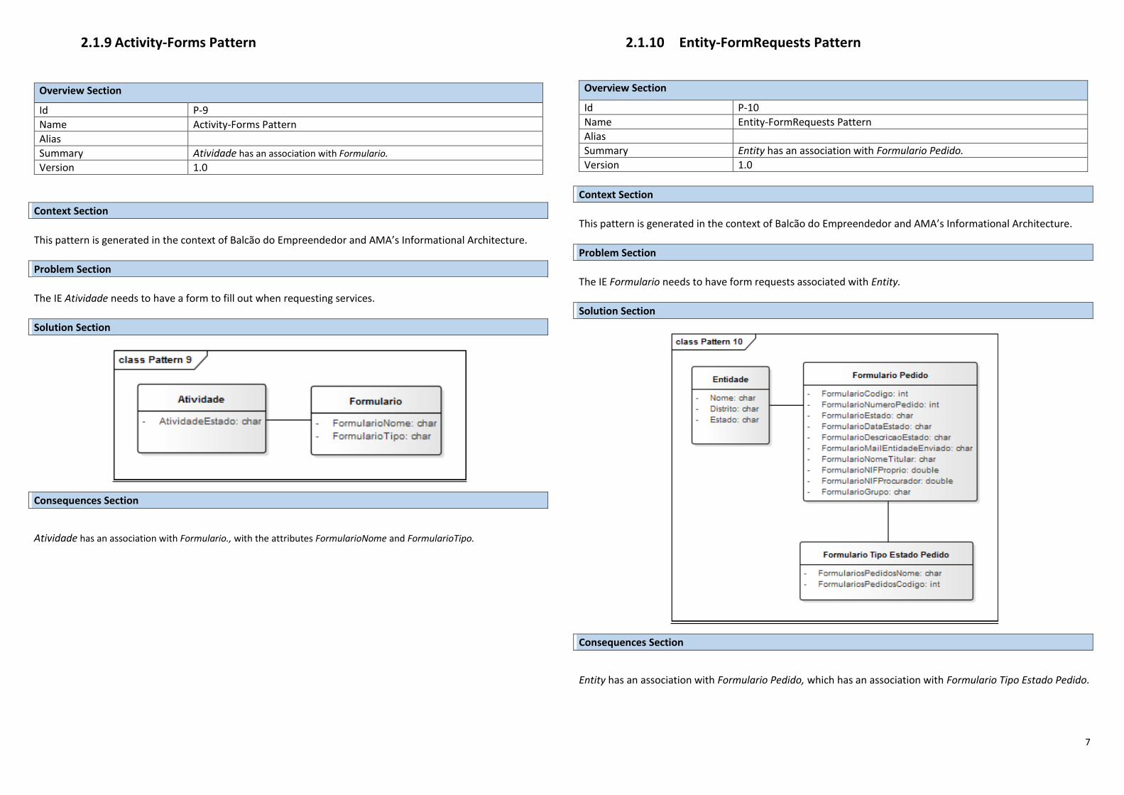
7
2.1.9 Activity-Forms Pattern
Overview Section
Id P-9
Name Activity-Forms Pattern
Alias
Summary Atividade has an association with Formulario.
Version 1.0
Context Section This pattern is generated in the context of Balcão do Empreendedor and AMA’s Informational Architecture.
Problem Section The IE Atividade needs to have a form to fill out when requesting services.
Solution Section
Consequences Section
Atividade has an association with Formulario., with the attributes FormularioNome and FormularioTipo.
2.1.10 Entity-FormRequests Pattern
Overview Section
Id P-10
Name Entity-FormRequests Pattern
Alias
Summary Entity has an association with Formulario Pedido.
Version 1.0
Context Section This pattern is generated in the context of Balcão do Empreendedor and AMA’s Informational Architecture.
Problem Section The IE Formulario needs to have form requests associated with Entity.
Solution Section
Consequences Section
Entity has an association with Formulario Pedido, which has an association with Formulario Tipo Estado Pedido.
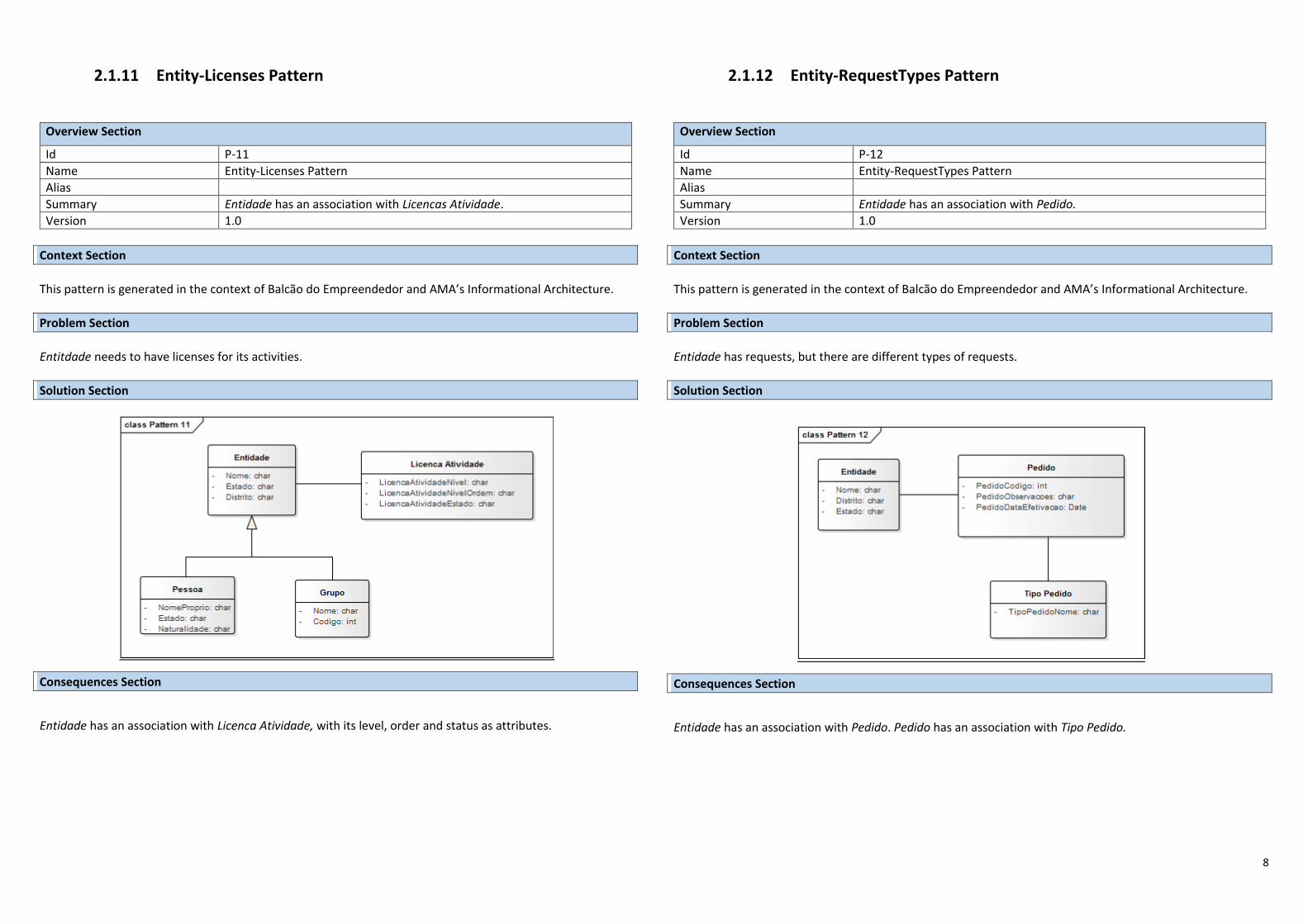
8
2.1.11 Entity-Licenses Pattern
Overview Section
Id P-11
Name Entity-Licenses Pattern
Alias
Summary Entidade has an association with Licencas Atividade.
Version 1.0
Context Section This pattern is generated in the context of Balcão do Empreendedor and AMA’s Informational Architecture.
Problem Section Entitdade needs to have licenses for its activities.
Solution Section
Consequences Section
Entidade has an association with Licenca Atividade, with its level, order and status as attributes.
2.1.12 Entity-RequestTypes Pattern
Overview Section
Id P-12
Name Entity-RequestTypes Pattern
Alias
Summary Entidade has an association with Pedido.
Version 1.0
Context Section This pattern is generated in the context of Balcão do Empreendedor and AMA’s Informational Architecture.
Problem Section Entidade has requests, but there are different types of requests.
Solution Section
Consequences Section
Entidade has an association with Pedido. Pedido has an association with Tipo Pedido.
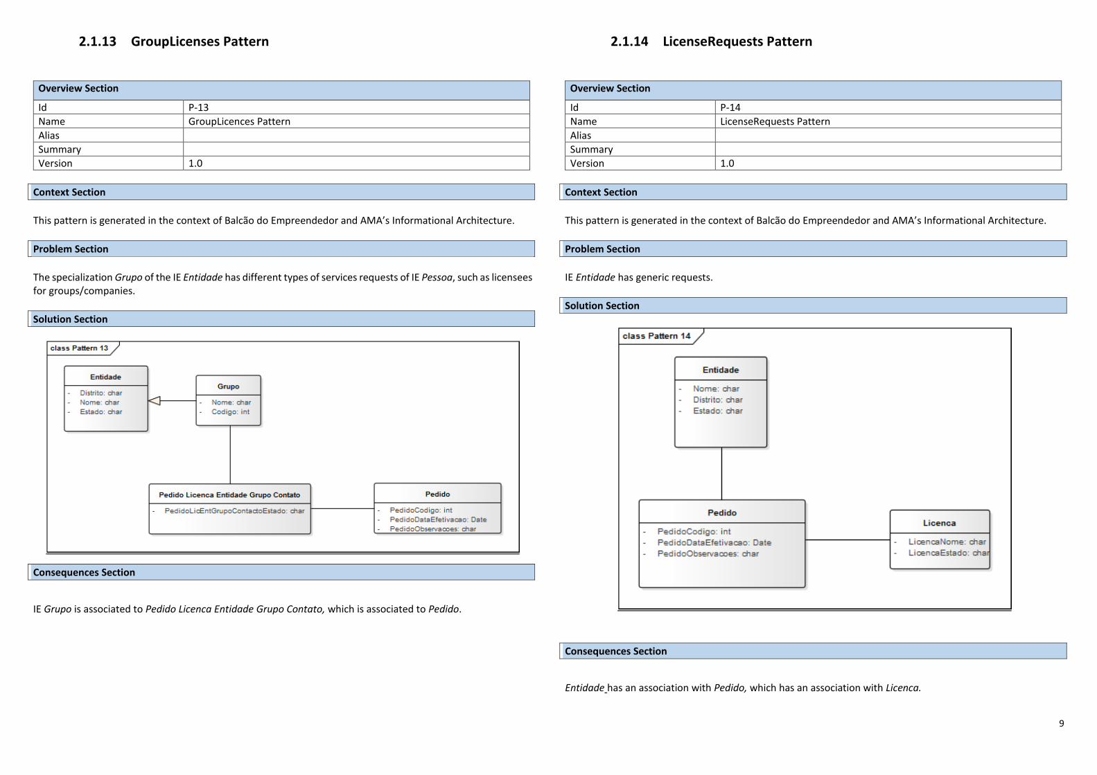
9
2.1.13 GroupLicenses Pattern
Overview Section
Id P-13
Name GroupLicences Pattern
Alias
Summary
Version 1.0
Context Section This pattern is generated in the context of Balcão do Empreendedor and AMA’s Informational Architecture.
Problem Section The specialization Grupo of the IE Entidade has different types of services requests of IE Pessoa, such as licensees for groups/companies.
Solution Section
Consequences Section
IE Grupo is associated to Pedido Licenca Entidade Grupo Contato, which is associated to Pedido.
2.1.14 LicenseRequests Pattern
Overview Section
Id P-14
Name LicenseRequests Pattern
Alias
Summary
Version 1.0
Context Section This pattern is generated in the context of Balcão do Empreendedor and AMA’s Informational Architecture.
Problem Section IE Entidade has generic requests.
Solution Section
Consequences Section
Entidade has an association with Pedido, which has an association with Licenca.
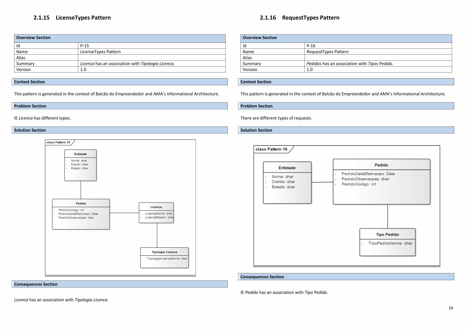
10
2.1.15 LicenseTypes Pattern
Overview Section
Id P-15
Name LicenseTypes Pattern
Alias
Summary Licenca has an association with Tipologia Licenca.
Version 1.0
Context Section This pattern is generated in the context of Balcão do Empreendedor and AMA’s Informational Architecture.
Problem Section IE Licenca has different types.
Solution Section
Consequences Section
Licenca has an association with Tipologia Licenca.
2.1.16 RequestTypes Pattern
Overview Section
Id P-16
Name RequestTypes Pattern
Alias
Summary Pedidos has an association with Tipos Pedido.
Version 1.0
Context Section This pattern is generated in the context of Balcão do Empreendedor and AMA’s Informational Architecture.
Problem Section There are different types of requests.
Solution Section
Consequences Section
IE Pedido has an association with Tipo Pedido.
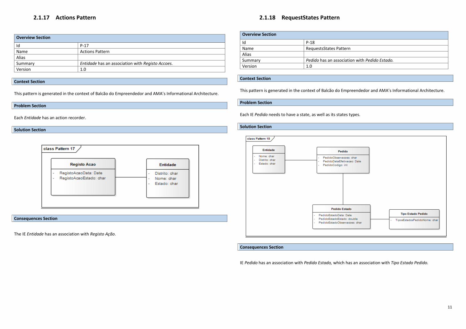
11
2.1.17 Actions Pattern
Overview Section
Id P-17
Name Actions Pattern
Alias
Summary Entidade has an association with Registo Accoes.
Version 1.0
Context Section This pattern is generated in the context of Balcão do Empreendedor and AMA’s Informational Architecture.
Problem Section Each Entidade has an action recorder.
Solution Section
Consequences Section
The IE Entidade has an association with Registo Ação.
2.1.18 RequestStates Pattern
Overview Section
Id P-18
Name RequestsStates Pattern
Alias
Summary Pedido has an association with Pedido Estado.
Version 1.0
Context Section This pattern is generated in the context of Balcão do Empreendedor and AMA’s Informational Architecture.
Problem Section Each IE Pedido needs to have a state, as well as its states types.
Solution Section
Consequences Section
IE Pedido has an association with Pedido Estado, which has an association with Tipo Estado Pedido.
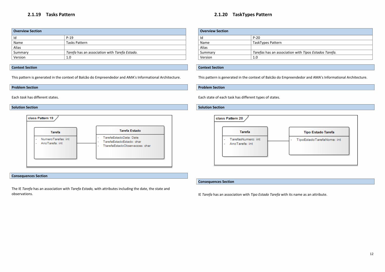
12
2.1.19 Tasks Pattern
Overview Section
Id P-19
Name Tasks Pattern
Alias
Summary Tarefa has an association with Tarefa Estado.
Version 1.0
Context Section This pattern is generated in the context of Balcão do Empreendedor and AMA’s Informational Architecture.
Problem Section Each task has different states.
Solution Section
Consequences Section
The IE Tarefa has an association with Tarefa Estado, with attributes including the date, the state and
observations.
2.1.20 TaskTypes Pattern
Overview Section
Id P-20
Name TaskTypes Pattern
Alias
Summary Tarefas has an association with Tipos Estados Tarefa.
Version 1.0
Context Section This pattern is generated in the context of Balcão do Empreendedor and AMA’s Informational Architecture.
Problem Section Each state of each task has different types of states.
Solution Section
Consequences Section
IE Tarefa has an association with Tipo Estado Tarefa with its name as an attribute.
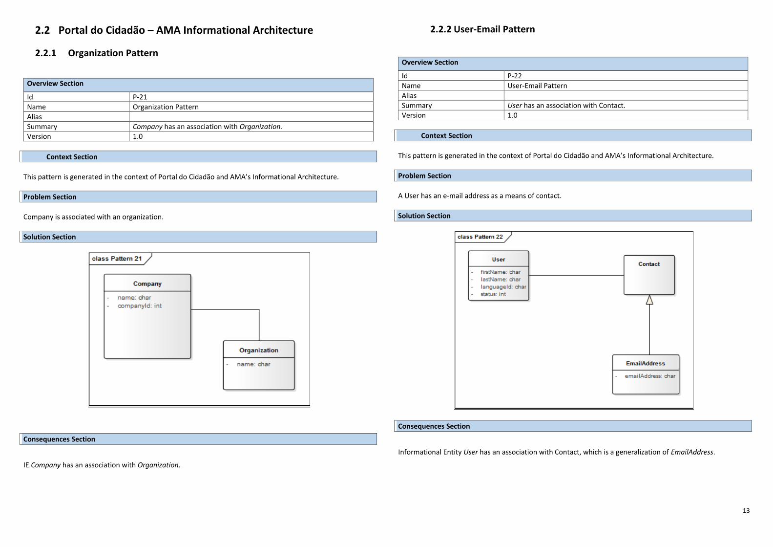
13
2.2 Portal do Cidadão – AMA Informational Architecture
2.2.1 Organization Pattern
Overview Section
Id P-21
Name Organization Pattern
Alias
Summary Company has an association with Organization.
Version 1.0
Context Section This pattern is generated in the context of Portal do Cidadão and AMA’s Informational Architecture.
Problem Section Company is associated with an organization.
Solution Section
Consequences Section
IE Company has an association with Organization.
2.2.2 User-Email Pattern
Overview Section
Id P-22
Name User-Email Pattern
Alias
Summary User has an association with Contact.
Version 1.0
Context Section This pattern is generated in the context of Portal do Cidadão and AMA’s Informational Architecture.
Problem Section A User has an e-mail address as a means of contact.
Solution Section
Consequences Section
Informational Entity User has an association with Contact, which is a generalization of EmailAddress.
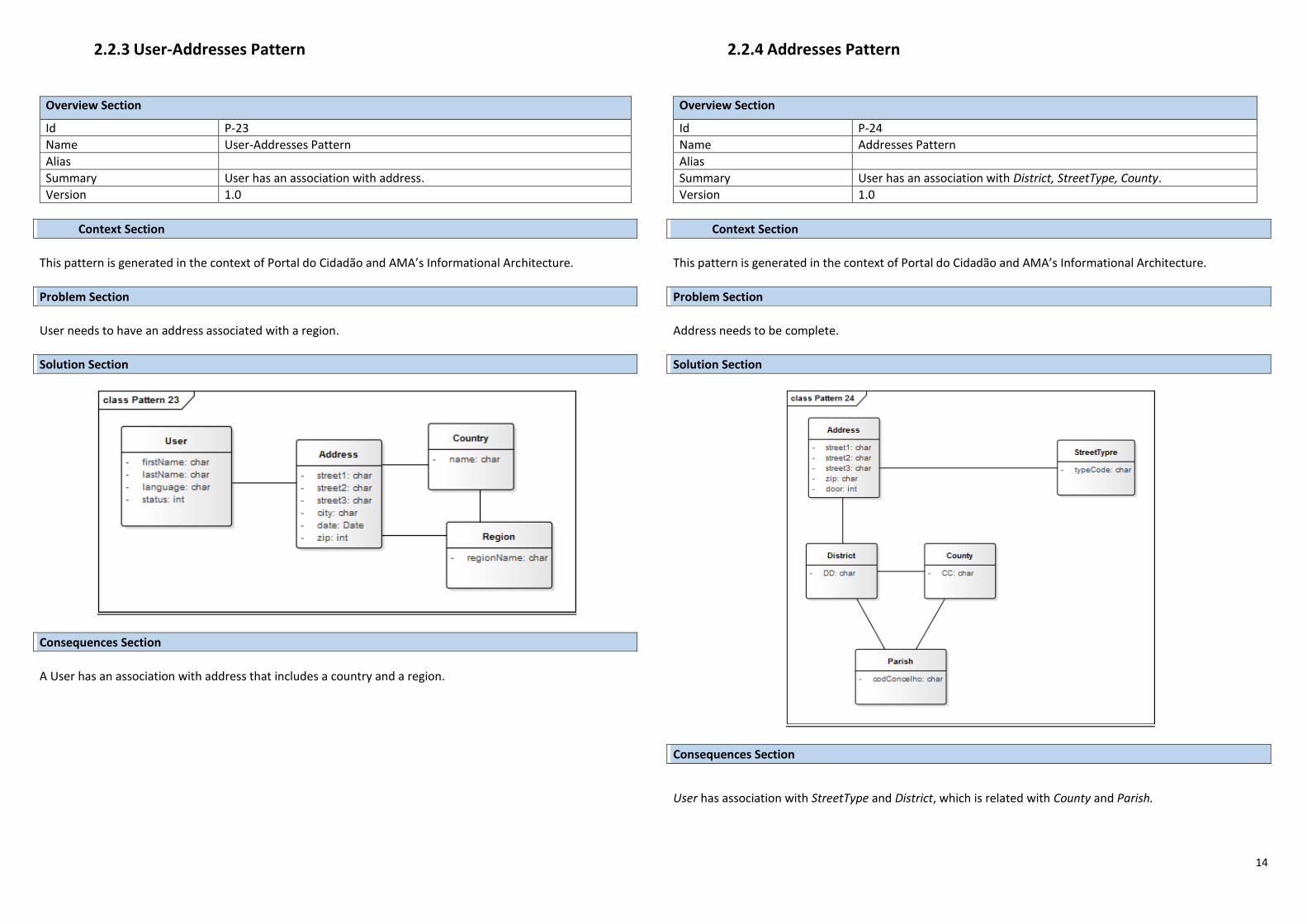
14
2.2.3 User-Addresses Pattern
Overview Section
Id P-23
Name User-Addresses Pattern
Alias
Summary User has an association with address.
Version 1.0
Context Section This pattern is generated in the context of Portal do Cidadão and AMA’s Informational Architecture.
Problem Section User needs to have an address associated with a region.
Solution Section
Consequences Section A User has an association with address that includes a country and a region.
2.2.4 Addresses Pattern
Overview Section
Id P-24
Name Addresses Pattern
Alias
Summary User has an association with District, StreetType, County.
Version 1.0
Context Section This pattern is generated in the context of Portal do Cidadão and AMA’s Informational Architecture.
Problem Section Address needs to be complete.
Solution Section
Consequences Section
User has association with StreetType and District, which is related with County and Parish.
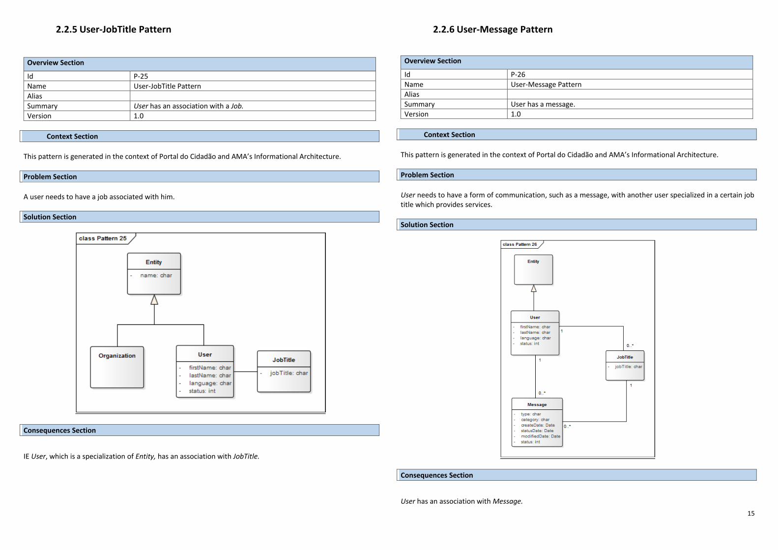
15
2.2.5 User-JobTitle Pattern
Overview Section
Id P-25
Name User-JobTitle Pattern
Alias
Summary User has an association with a Job.
Version 1.0
Context Section This pattern is generated in the context of Portal do Cidadão and AMA’s Informational Architecture.
Problem Section A user needs to have a job associated with him.
Solution Section
Consequences Section
IE User, which is a specialization of Entity, has an association with JobTitle.
2.2.6 User-Message Pattern
Overview Section
Id P-26
Name User-Message Pattern
Alias
Summary User has a message.
Version 1.0
Context Section This pattern is generated in the context of Portal do Cidadão and AMA’s Informational Architecture.
Problem Section User needs to have a form of communication, such as a message, with another user specialized in a certain job title which provides services.
Solution Section
Consequences Section
User has an association with Message.
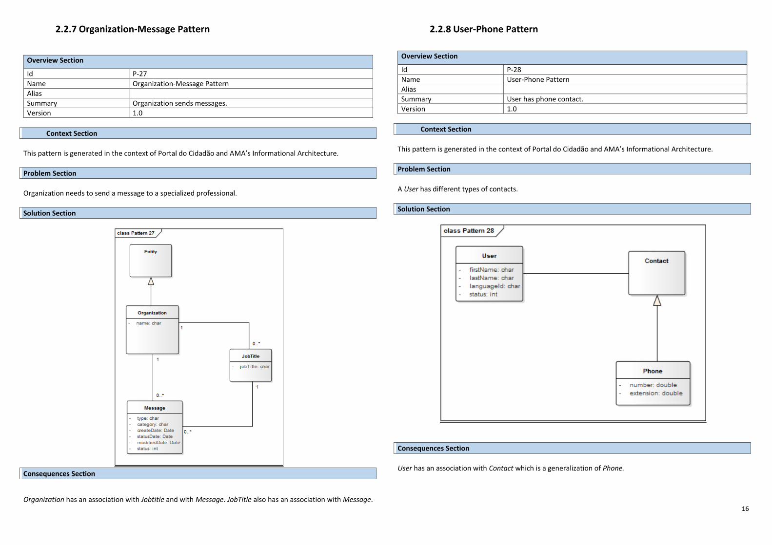
16
2.2.7 Organization-Message Pattern
Overview Section
Id P-27
Name Organization-Message Pattern
Alias
Summary Organization sends messages.
Version 1.0
Context Section This pattern is generated in the context of Portal do Cidadão and AMA’s Informational Architecture.
Problem Section Organization needs to send a message to a specialized professional.
Solution Section
Consequences Section
Organization has an association with Jobtitle and with Message. JobTitle also has an association with Message.
2.2.8 User-Phone Pattern
Overview Section
Id P-28
Name User-Phone Pattern
Alias
Summary User has phone contact.
Version 1.0
Context Section This pattern is generated in the context of Portal do Cidadão and AMA’s Informational Architecture.
Problem Section A User has different types of contacts.
Solution Section
Consequences Section User has an association with Contact which is a generalization of Phone.
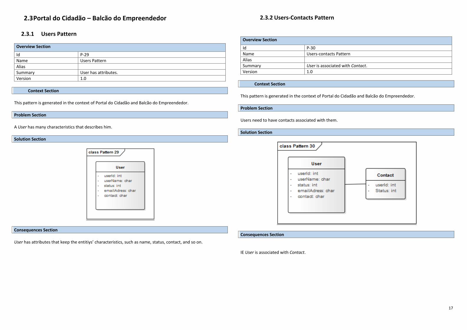
17
2.3 Portal do Cidadão – Balcão do Empreendedor 2.3.1 Users Pattern
Overview Section
Id P-29
Name Users Pattern
Alias
Summary User has attributes.
Version 1.0
Context Section This pattern is generated in the context of Portal do Cidadão and Balcão do Empreendedor.
Problem Section A User has many characteristics that describes him.
Solution Section
Consequences Section
User has attributes that keep the entitiys’ characteristics, such as name, status, contact, and so on.
2.3.2 Users-Contacts Pattern
Overview Section
Id P-30
Name Users-contacts Pattern
Alias
Summary User is associated with Contact.
Version 1.0
Context Section This pattern is generated in the context of Portal do Cidadão and Balcão do Empreendedor.
Problem Section Users need to have contacts associated with them.
Solution Section
Consequences Section
IE User is associated with Contact.
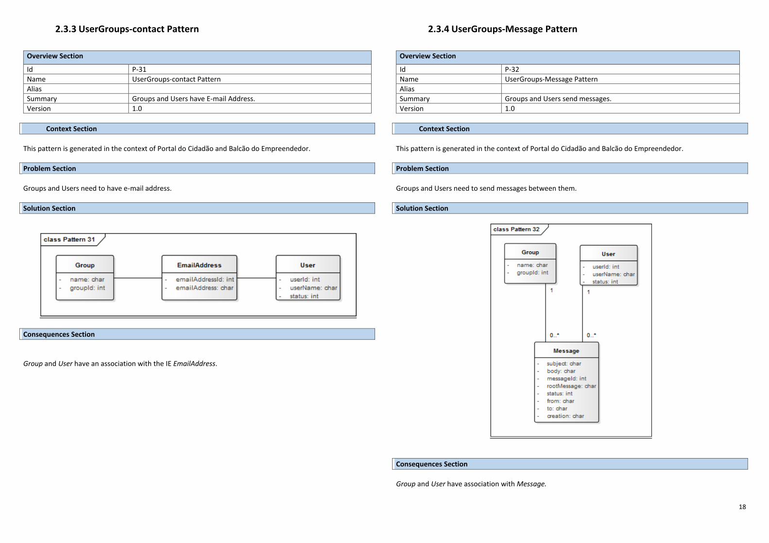
18
2.3.3 UserGroups-contact Pattern
Overview Section
Id P-31
Name UserGroups-contact Pattern
Alias
Summary Groups and Users have E-mail Address.
Version 1.0
Context Section This pattern is generated in the context of Portal do Cidadão and Balcão do Empreendedor.
Problem Section Groups and Users need to have e-mail address.
Solution Section
Consequences Section
Group and User have an association with the IE EmailAddress.
2.3.4 UserGroups-Message Pattern
Overview Section
Id P-32
Name UserGroups-Message Pattern
Alias
Summary Groups and Users send messages.
Version 1.0
Context Section This pattern is generated in the context of Portal do Cidadão and Balcão do Empreendedor.
Problem Section Groups and Users need to send messages between them.
Solution Section
Consequences Section
Group and User have association with Message.
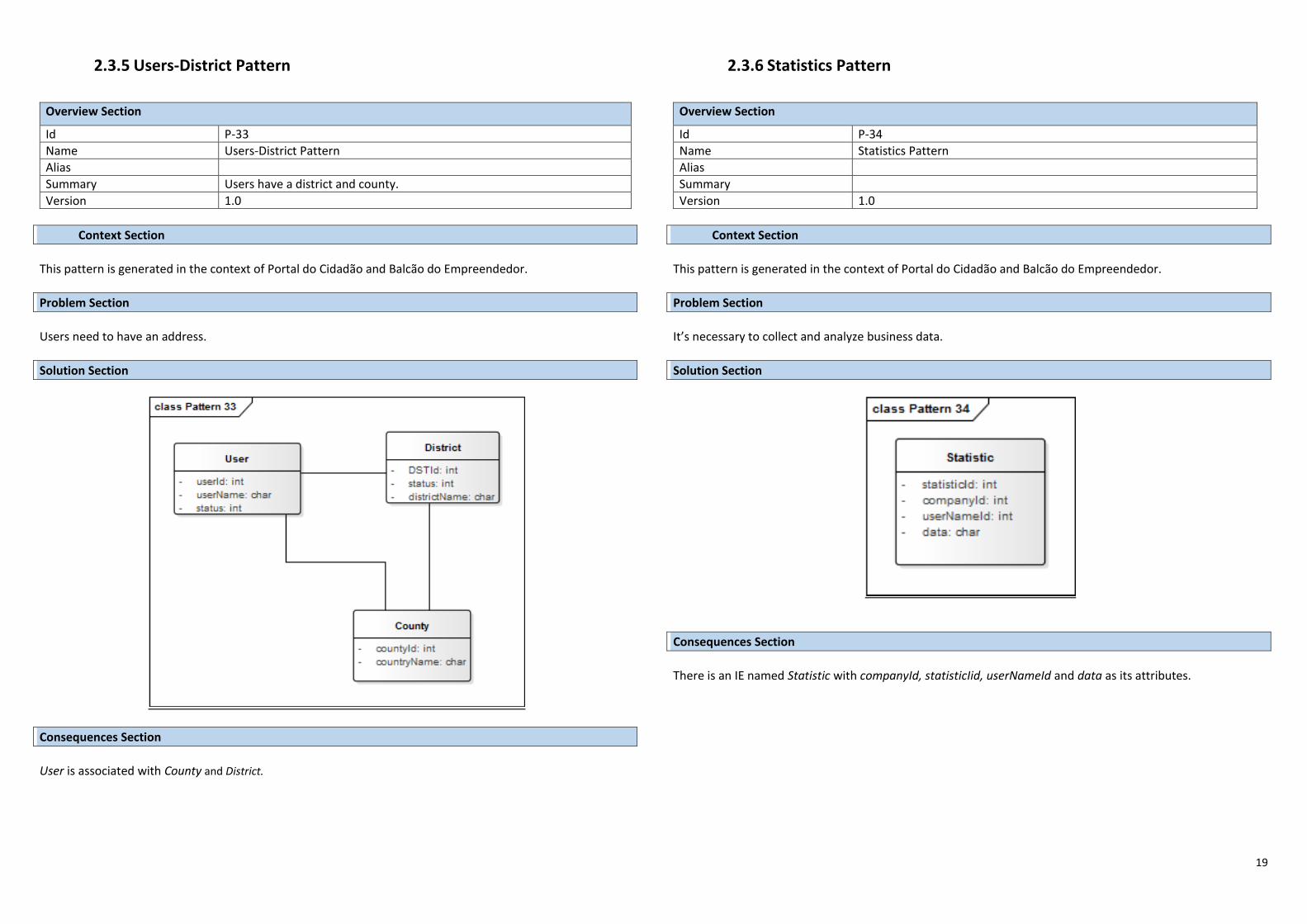
19
2.3.5 Users-District Pattern
Overview Section
Id P-33
Name Users-District Pattern
Alias
Summary Users have a district and county.
Version 1.0
Context Section This pattern is generated in the context of Portal do Cidadão and Balcão do Empreendedor.
Problem Section Users need to have an address.
Solution Section
Consequences Section
User is associated with County and District.
2.3.6 Statistics Pattern
Overview Section
Id P-34
Name Statistics Pattern
Alias
Summary
Version 1.0
Context Section This pattern is generated in the context of Portal do Cidadão and Balcão do Empreendedor.
Problem Section It’s necessary to collect and analyze business data.
Solution Section
Consequences Section
There is an IE named Statistic with companyId, statisticIid, userNameId and data as its attributes.
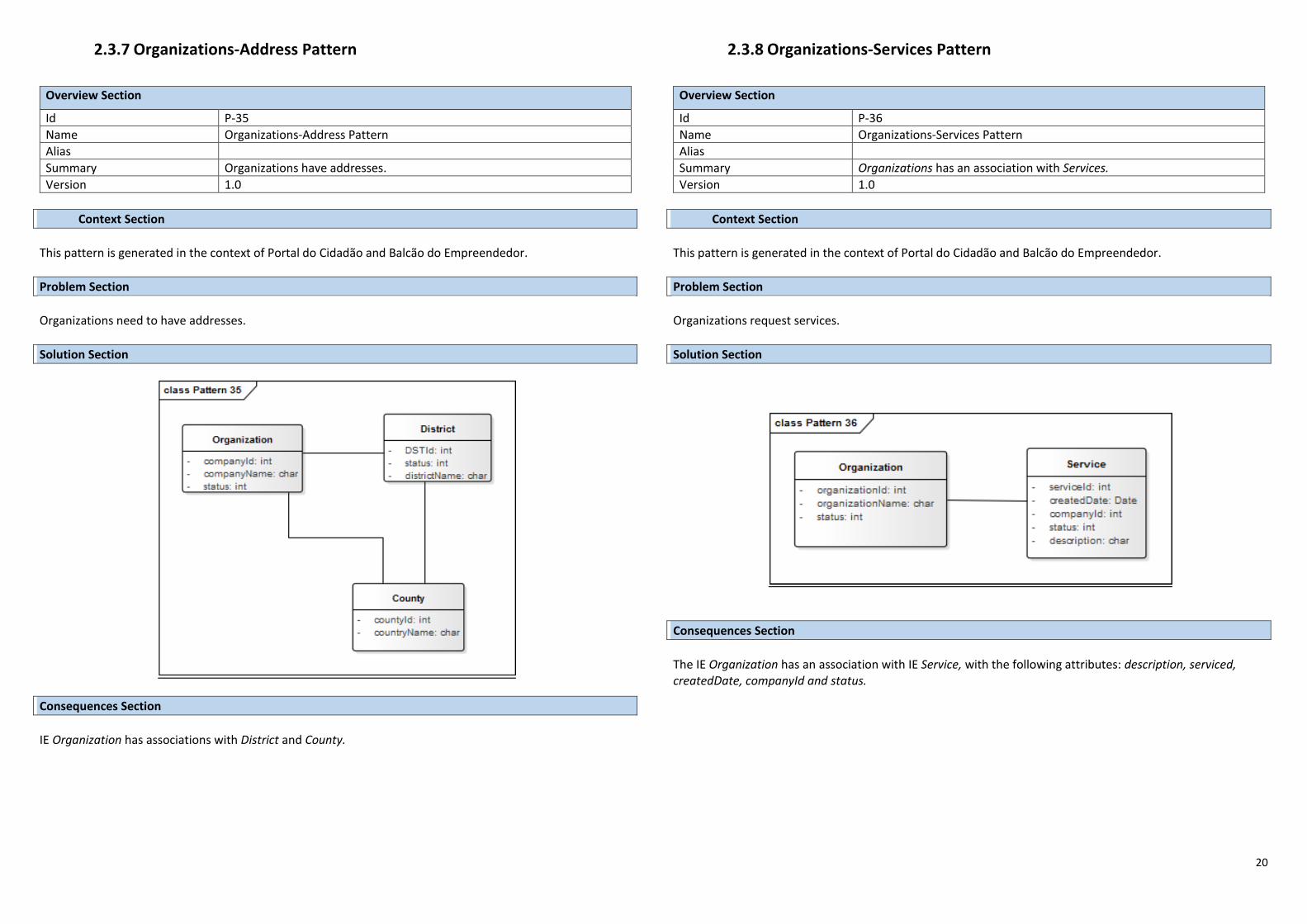
20
2.3.7 Organizations-Address Pattern
Overview Section
Id P-35
Name Organizations-Address Pattern
Alias
Summary Organizations have addresses.
Version 1.0
Context Section This pattern is generated in the context of Portal do Cidadão and Balcão do Empreendedor.
Problem Section Organizations need to have addresses.
Solution Section
Consequences Section
IE Organization has associations with District and County.
2.3.8 Organizations-Services Pattern
Overview Section
Id P-36
Name Organizations-Services Pattern
Alias
Summary Organizations has an association with Services.
Version 1.0
Context Section This pattern is generated in the context of Portal do Cidadão and Balcão do Empreendedor.
Problem Section Organizations request services.
Solution Section
Consequences Section
The IE Organization has an association with IE Service, with the following attributes: description, serviced, createdDate, companyId and status.
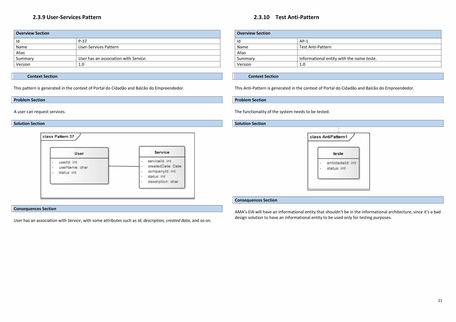
21
2.3.9 User-Services Pattern
Overview Section
Id P-37
Name User-Services Pattern
Alias
Summary User has an association with Service.
Version 1.0
Context Section This pattern is generated in the context of Portal do Cidadão and Balcão do Empreendedor.
Problem Section A user can request services.
Solution Section
Consequences Section
User has an association with Service, with some attributes such as Id, description, created data, and so on.
2.3.10 Test Anti-Pattern
Overview Section
Id AP-1
Name Test Anti-Pattern
Alias
Summary Informational entity with the name teste.
Version 1.0
Context Section This Anti-Pattern is generated in the context of Portal do Cidadão and Balcão do Empreendedor.
Problem Section The functionality of the system needs to be tested.
Solution Section ´
Consequences Section
AMA’s EIA will have an informational entity that shouldn’t be in the informational architecture, since it’s a bad design solution to have an informational entity to be used only for testing purposes.
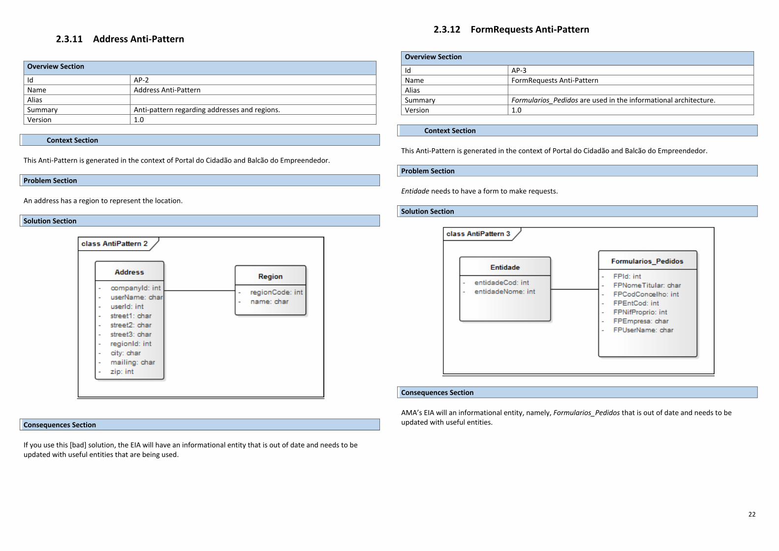
22
2.3.11 Address Anti-Pattern
Overview Section
Id AP-2
Name Address Anti-Pattern
Alias
Summary Anti-pattern regarding addresses and regions.
Version 1.0
Context Section This Anti-Pattern is generated in the context of Portal do Cidadão and Balcão do Empreendedor.
Problem Section An address has a region to represent the location.
Solution Section
Consequences Section
If you use this [bad] solution, the EIA will have an informational entity that is out of date and needs to be updated with useful entities that are being used.
2.3.12 FormRequests Anti-Pattern
Overview Section
Id AP-3
Name FormRequests Anti-Pattern
Alias
Summary Formularios_Pedidos are used in the informational architecture.
Version 1.0
Context Section This Anti-Pattern is generated in the context of Portal do Cidadão and Balcão do Empreendedor.
Problem Section Entidade needs to have a form to make requests.
Solution Section
Consequences Section AMA’s EIA will an informational entity, namely, Formularios_Pedidos that is out of date and needs to be updated with useful entities.


![Science of Computer Programmingpvelasco/files/2016... · Science of Computer Programming. ... Patterns of Enterprise Application Architecture [6], Service Oriented Architecture (SOA)](https://img.pdfslide.net/doc/110x75/605094d690a9227b817bcff0/science-of-computer-programming-pvelascofiles2016-science-of-computer-programming.jpg)