Embed Size (px)
Citation preview

Environmental Controls I/IGEnvironmental Controls I/IGEnvironmental Controls I/IGEnvironmental Controls I/IG
Lecture 7
Upfeed SystemsPipe Sizing Procedure Pipe Sizing Example
Lecture 7
Upfeed SystemsPipe Sizing Procedure Pipe Sizing Example

Upfeed SystemsUpfeed SystemsUpfeed SystemsUpfeed Systems
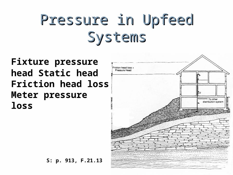
Pressure in Upfeed SystemsPressure in Upfeed Systems
Fixture pressure head Static headFriction head lossMeter pressure loss
S: p. 913, F.21.13
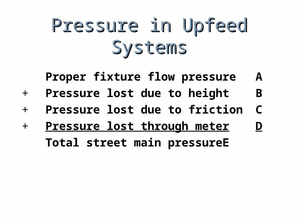
Pressure in Upfeed SystemsPressure in Upfeed Systems
Proper fixture flow pressureA+ Pressure lost due to heightB+ Pressure lost due to frictionC+ Pressure lost through meterD Total street main pressure E
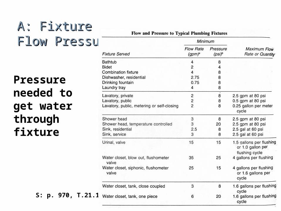
A: FixtureA: FixtureFlow PressureFlow Pressure
Pressure needed to get water through fixture
S: p. 970, T.21.14
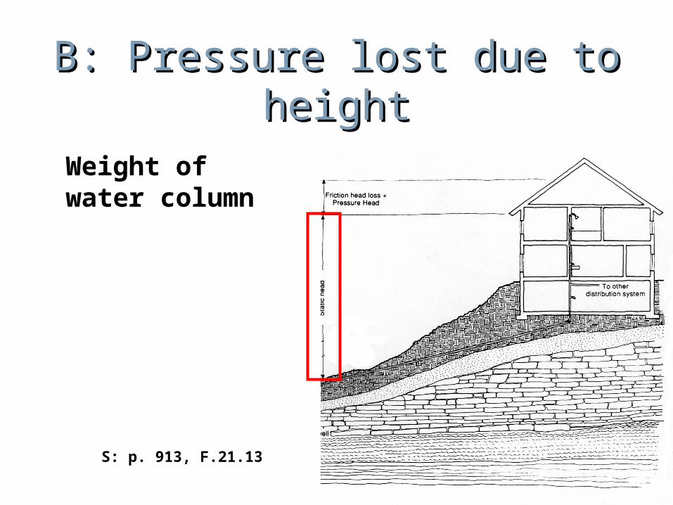
B: Pressure lost due to B: Pressure lost due to heightheight
Weight of water column
S: p. 913, F.21.13
C: Pressure loss due to C: Pressure loss due to frictionfriction
Initially unknown, must be calculated based on pressure remaining after accounting for the other factors
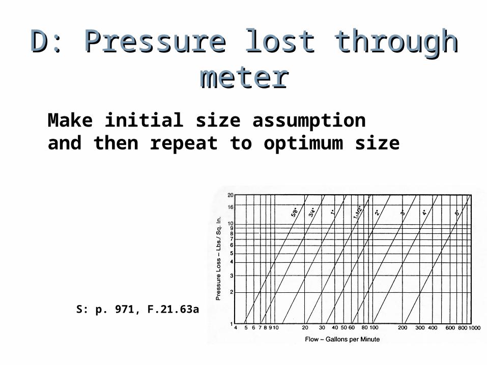
D: Pressure lost through D: Pressure lost through metermeter
Make initial size assumption and then repeat to optimum size
S: p. 971, F.21.63a
E: Total Street Main E: Total Street Main PressurePressure
Check with water company or fire department
Pipe Sizing ProcedurePipe Sizing ProcedurePipe Sizing ProcedurePipe Sizing Procedure
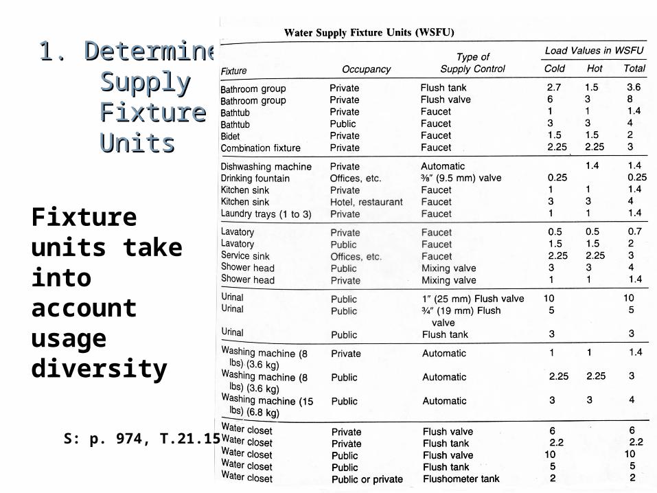
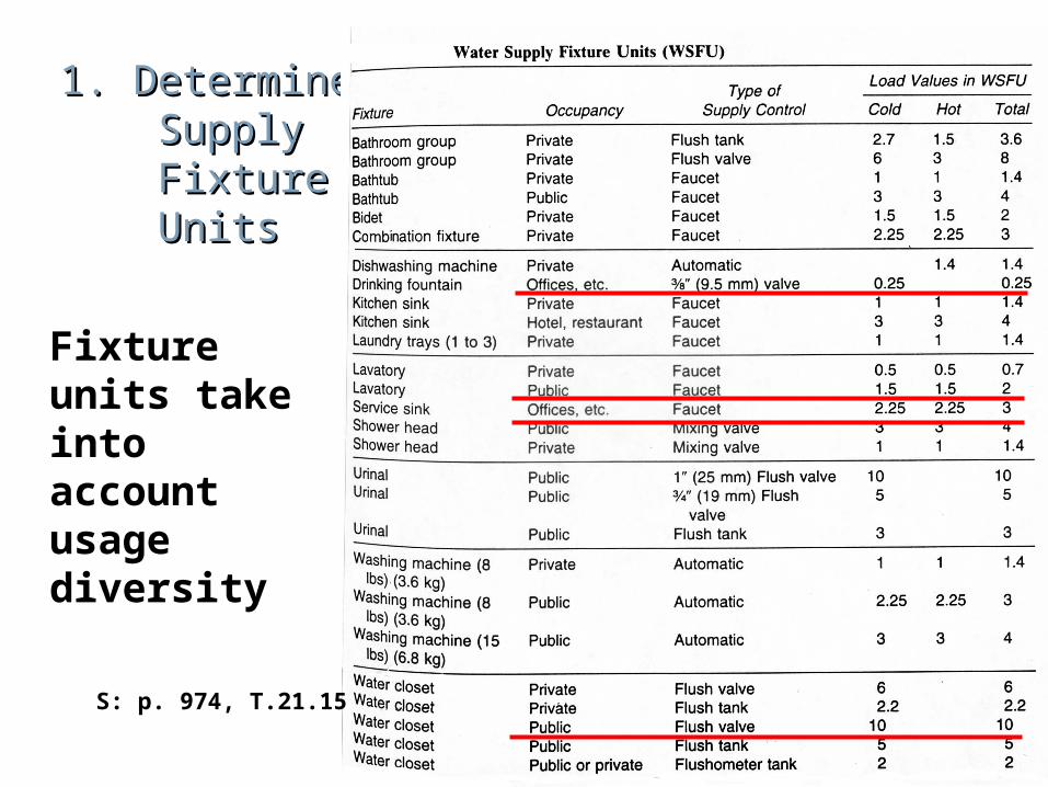
1. Determine 1. Determine Supply Supply Fixture Fixture Units Units
Fixture units take into account usage diversity
S: p. 974, T.21.15
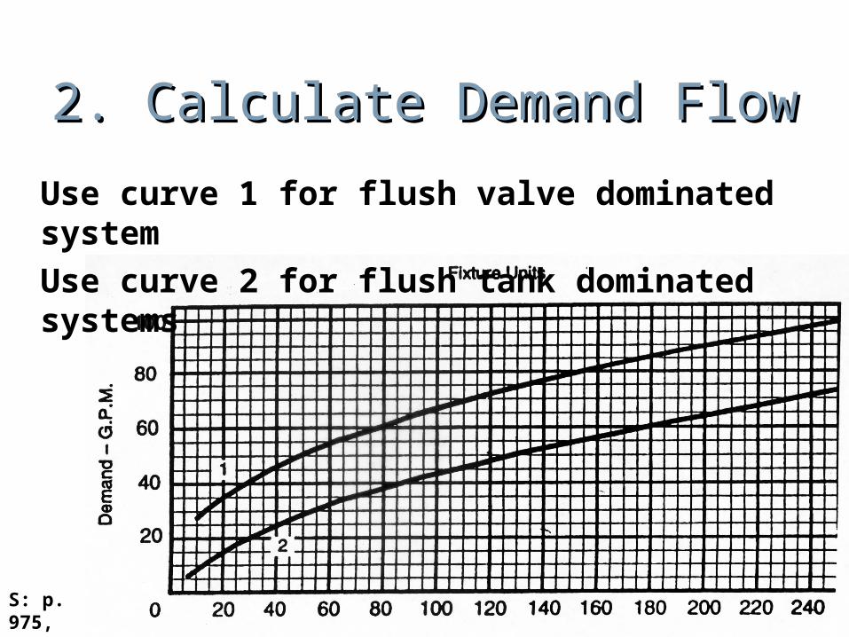
2. Calculate Demand Flow2. Calculate Demand Flow
Use curve 1 for flush valve dominated systemUse curve 2 for flush tank dominated systems
S: p. 975, F.21.65a
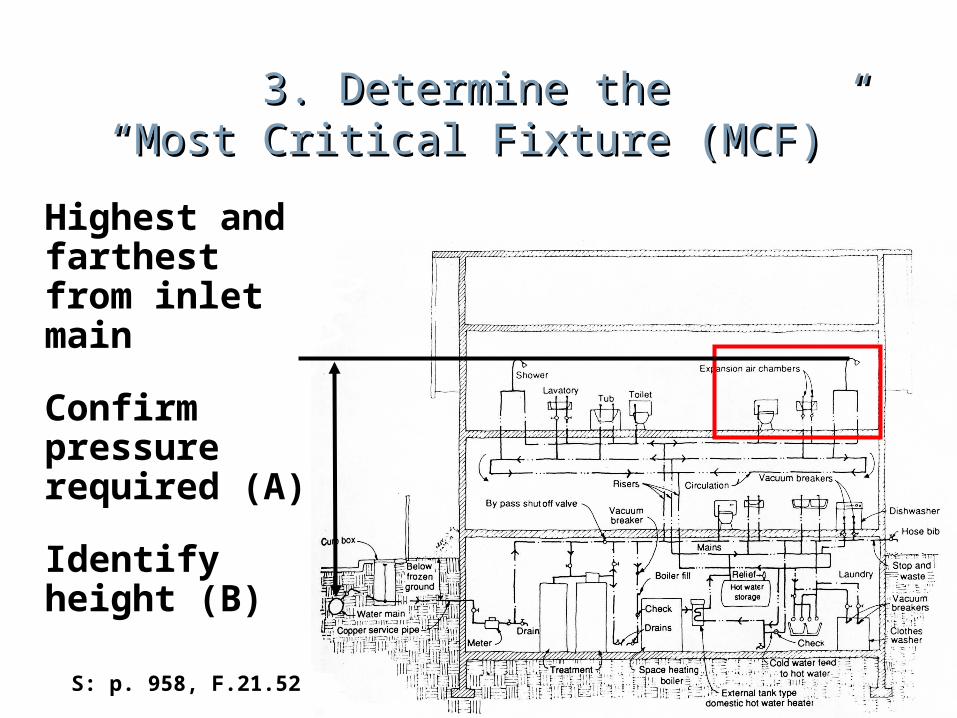
3. Determine the 3. Determine the “Most Critical Fixture (MCF)”“Most Critical Fixture (MCF)”
Highest and farthest from inlet main
Confirm pressure required (A)
Identify height (B)
S: p. 958, F.21.52
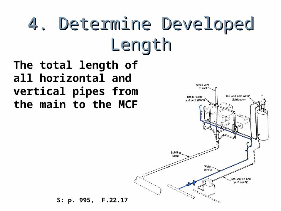
4. Determine Developed 4. Determine Developed LengthLength
The total length of all horizontal and vertical pipes from the main to the MCF
S: p. 995, F.22.17
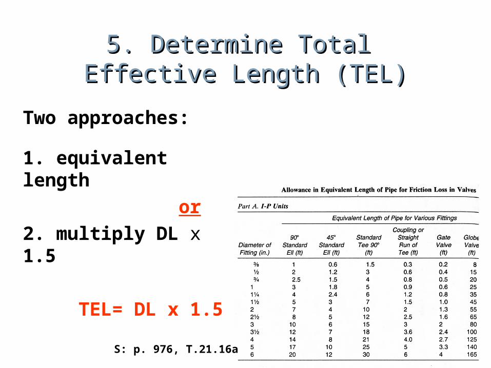
5. Determine Total 5. Determine Total Effective Length (TEL)Effective Length (TEL)
Two approaches:
1. equivalent length or2. multiply DL x 1.5
TEL= DL x 1.5
S: p. 976, T.21.16a
6. Determine Street 6. Determine Street Main Pressure (E)Main Pressure (E)
Contact utility company or fire department
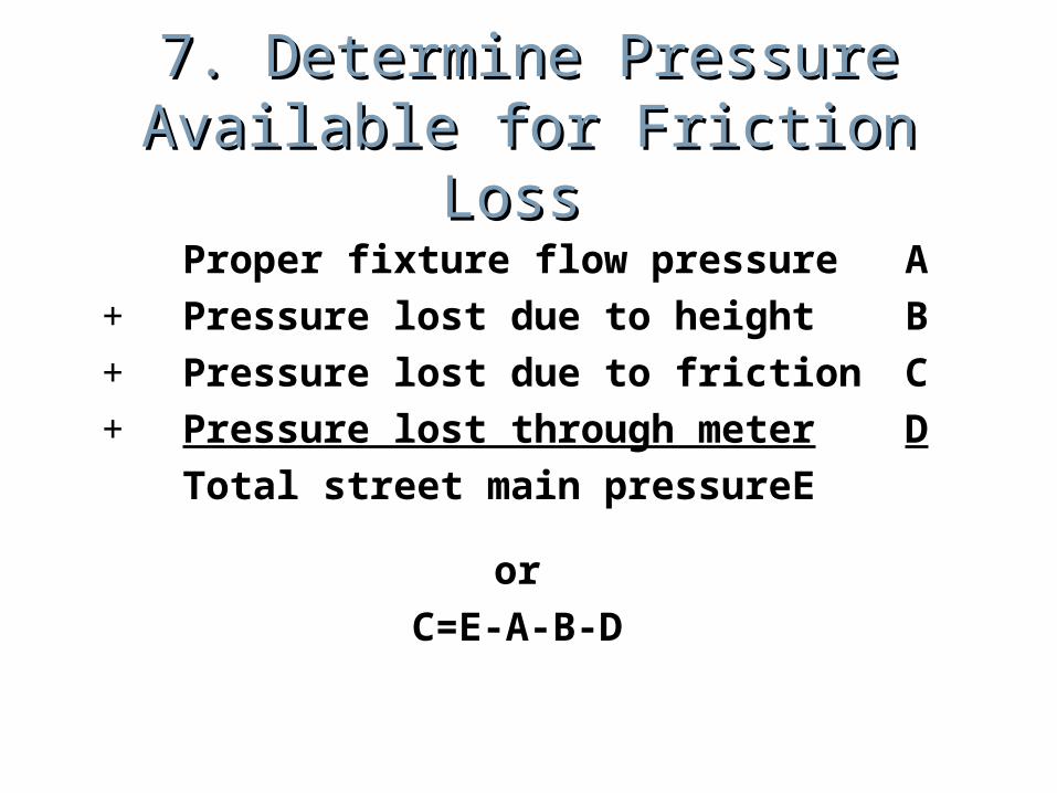
7. Determine Pressure 7. Determine Pressure Available for Friction Loss Available for Friction Loss
Proper fixture flow pressureA+ Pressure lost due to heightB+ Pressure lost due to frictionC+ Pressure lost through meter D Total street main pressure E
orC=E-A-B-D
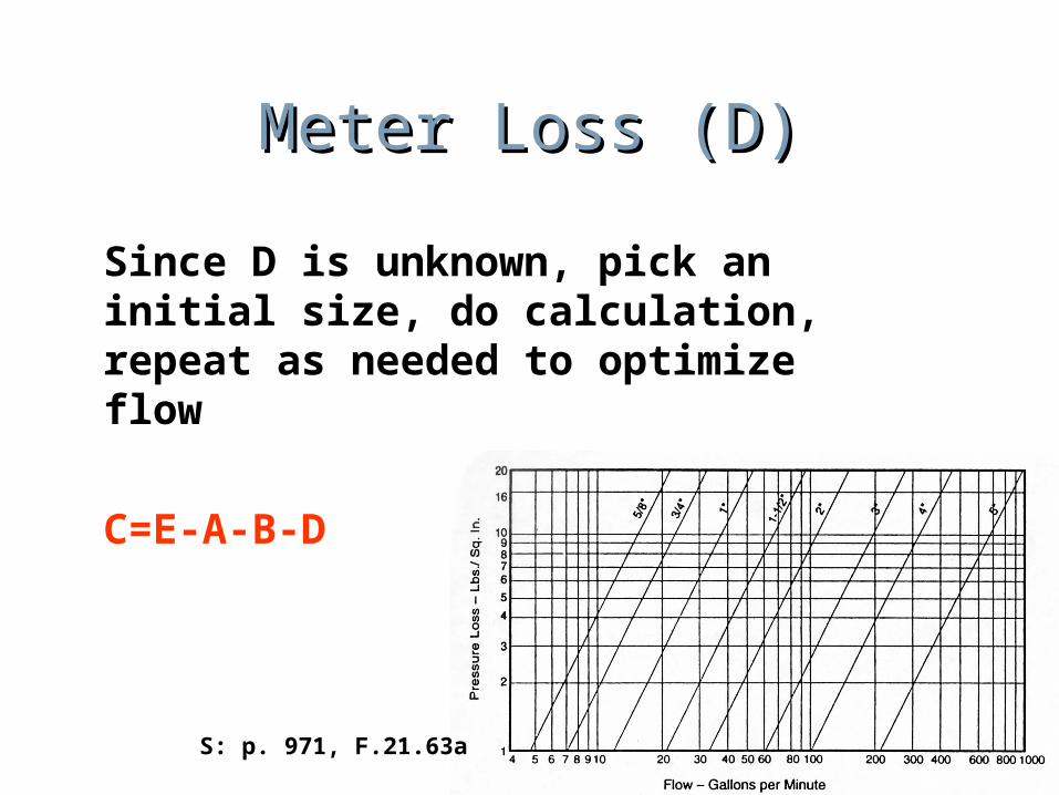
Meter Loss (D)Meter Loss (D)
Since D is unknown, pick an initial size, do calculation, repeat as needed to optimize flow
C=E-A-B-D
S: p. 971, F.21.63a
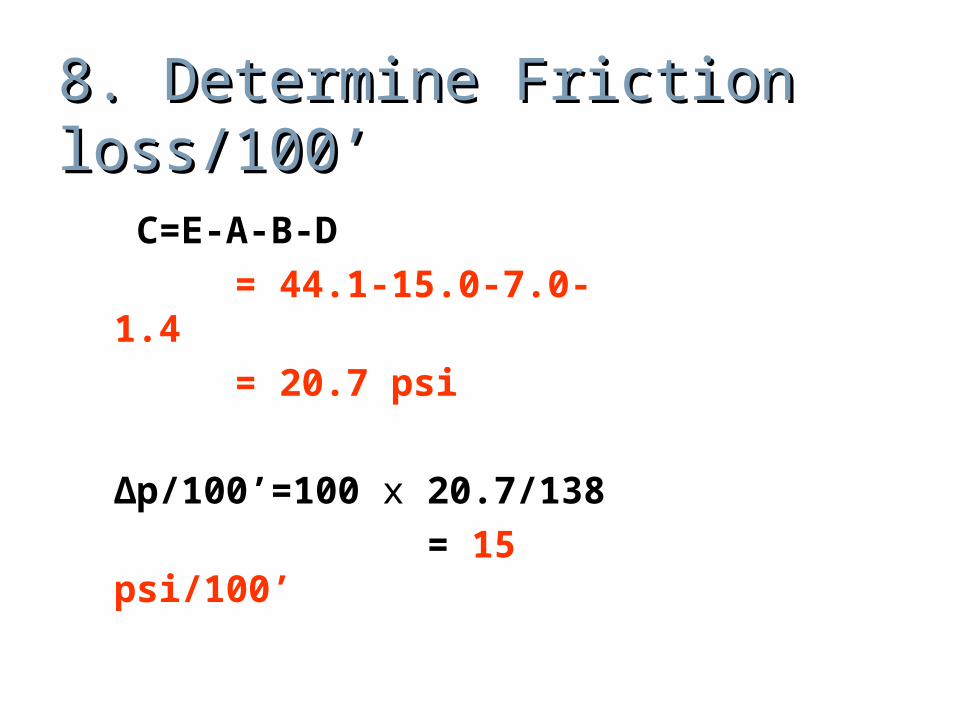
8. Determine Friction 8. Determine Friction loss/100’loss/100’
C=E-A-B-D
Δp/100’ = 100 x C/TEL
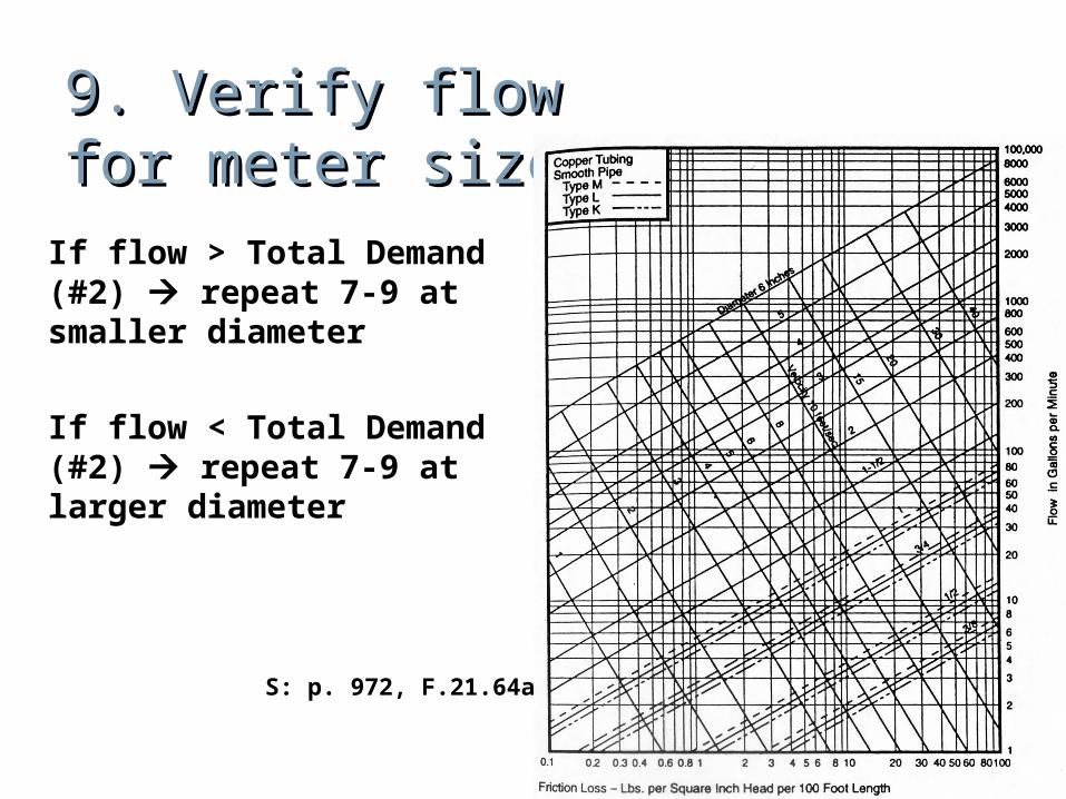
9. Verify flow 9. Verify flow for meter sizefor meter size
If flow > Total Demand (#2) repeat 7-9 at smaller diameter
If flow < Total Demand (#2) repeat 7-9 at larger diameter
S: p. 972, F.21.64a
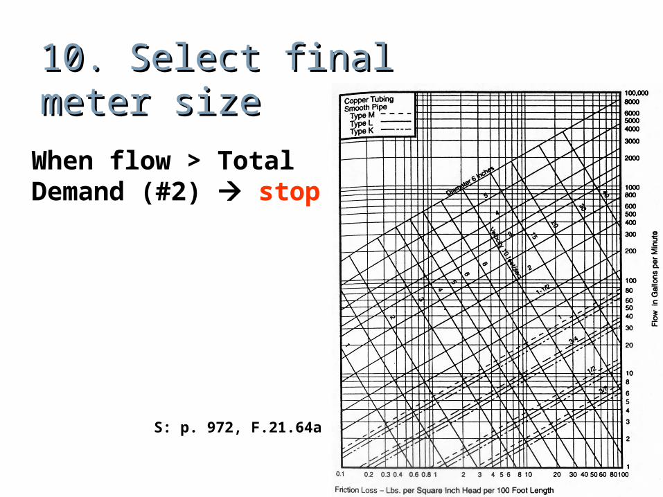
10. Select final10. Select finalmeter sizemeter size
When flow > Total Demand (#2) stop
S: p. 972, F.21.64a
Pipe Sizing ExamplePipe Sizing ExamplePipe Sizing ExamplePipe Sizing Example
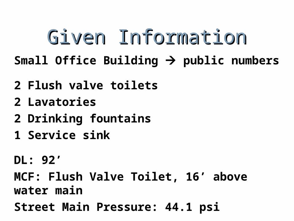
Given InformationGiven InformationSmall Office Building public numbers
2 Flush valve toilets2 Lavatories2 Drinking fountains1 Service sink
DL: 92’MCF: Flush Valve Toilet, 16’ above water mainStreet Main Pressure: 44.1 psi
1. Determine 1. Determine Supply Supply Fixture Fixture Units Units
Fixture units take into account usage diversity
S: p. 974, T.21.15
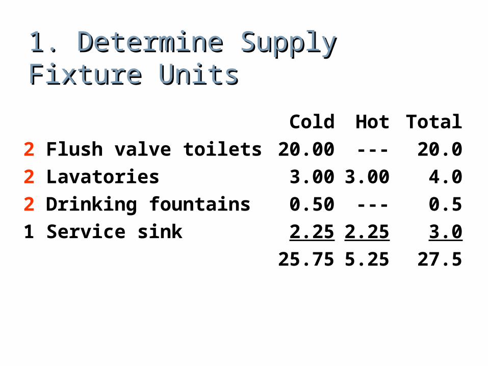
1. Determine Supply Fixture 1. Determine Supply Fixture UnitsUnits
Cold Hot Total2 Flush valve toilets 20.00 --- 20.02 Lavatories 3.00 3.00 4.02 Drinking fountains 0.50 --- 0.51 Service sink 2.25 2.25 3.0
25.75 5.25 27.5
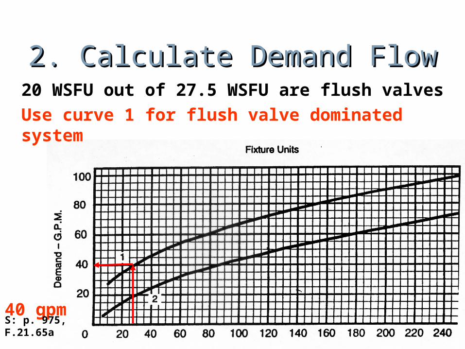
2. Calculate Demand Flow2. Calculate Demand Flow20 WSFU out of 27.5 WSFU are flush valves Use curve 1 for flush valve dominated system
40 gpmS: p. 975, F.21.65a
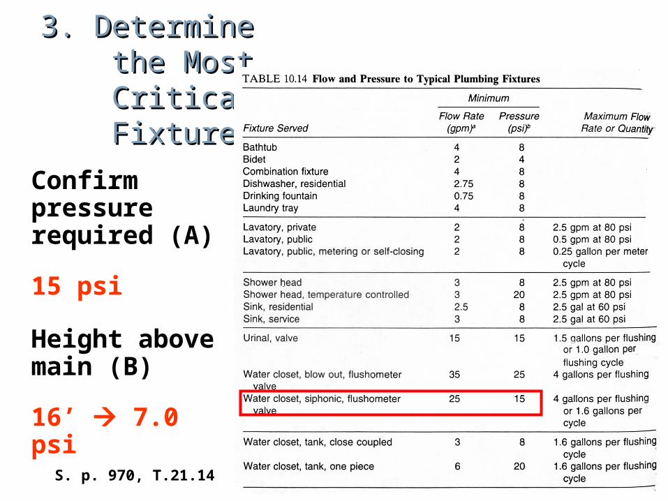
3. Determine 3. Determine the Most the Most Critical Critical Fixture Fixture
Confirm pressure required (A)
15 psi
Height above main (B)
16’ 7.0 psiS. p. 970, T.21.14
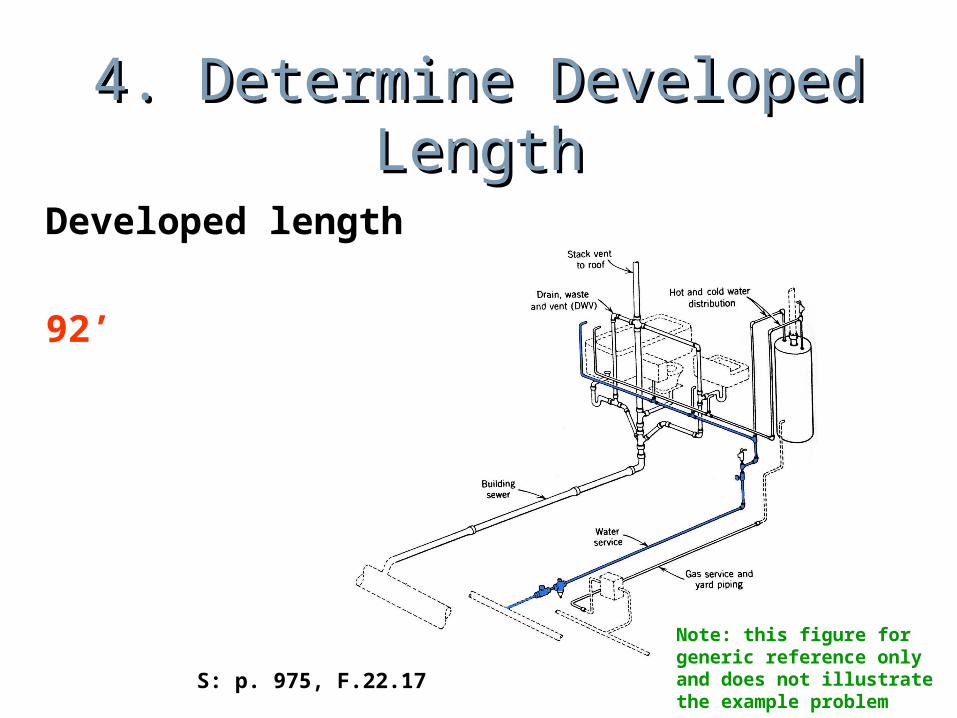
4. Determine Developed 4. Determine Developed LengthLength
Developed length
92’
S: p. 975, F.22.17
Note: this figure for generic reference only and does not illustrate the example problem
5. Determine Total 5. Determine Total Effective Length (TEL)Effective Length (TEL)
TEL= DL x 1.5 = 92 x 1.5 = 138’
6. Determine Street 6. Determine Street Main Pressure (E)Main Pressure (E)
44.1 psi
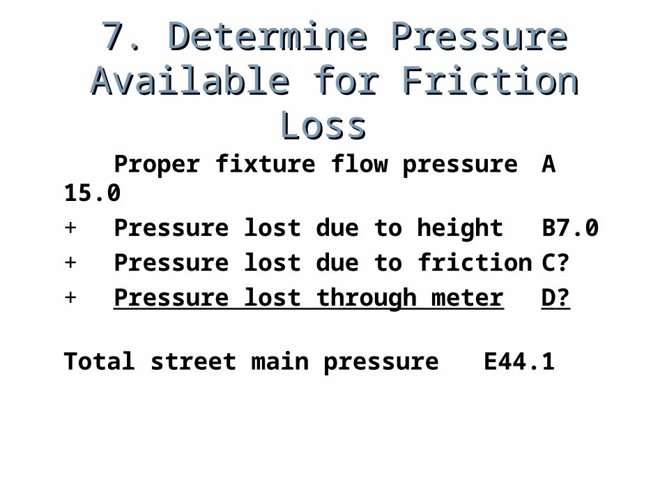
7. Determine Pressure 7. Determine Pressure Available for Friction Loss Available for Friction Loss
Proper fixture flow pressureA15.0+ Pressure lost due to heightB7.0+ Pressure lost due to frictionC ?+ Pressure lost through meter D?
Total street main pressure E44.1
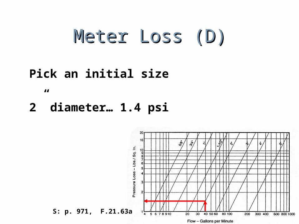
Meter Loss (D)Meter Loss (D)
Pick an initial size
2” diameter… 1.4 psi
S: p. 971, F.21.63a
8. Determine Friction 8. Determine Friction loss/100’loss/100’
C=E-A-B-D = 44.1-15.0-7.0-1.4 = 20.7 psi
Δp/100’=100 x 20.7/138 = 15 psi/100’
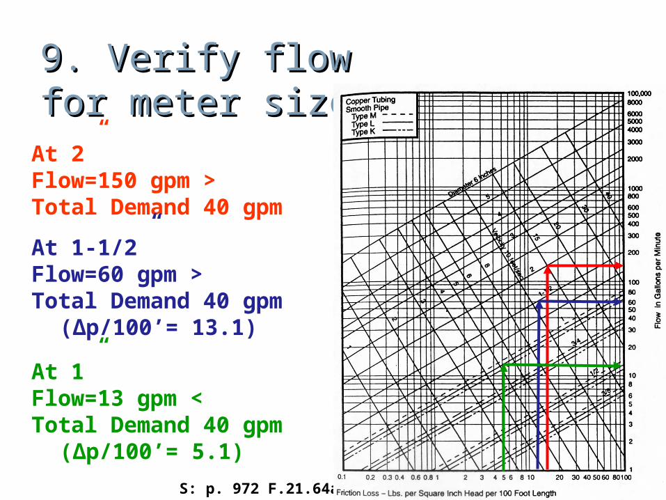
9. Verify flow 9. Verify flow for meter sizefor meter size
At 2” Flow=150 gpm > Total Demand 40 gpm
At 1-1/2”Flow=60 gpm > Total Demand 40 gpm
(Δp/100’= 13.1)
At 1”Flow=13 gpm < Total Demand 40 gpm
(Δp/100’= 5.1)S: p. 972 F.21.64a
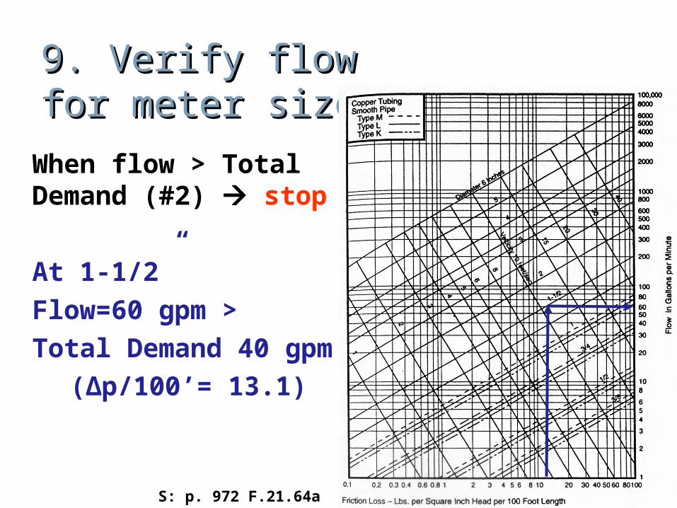
9. Verify flow 9. Verify flow for meter sizefor meter size
When flow > Total Demand (#2) stop
At 1-1/2”Flow=60 gpm > Total Demand 40 gpm
(Δp/100’= 13.1)
S: p. 972 F.21.64a
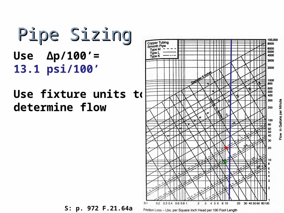
Pipe SizingPipe SizingUse Δp/100’= 13.1 psi/100’
Use fixture units to determine flow
S: p. 972 F.21.64a
Pipe SizingPipe Sizing
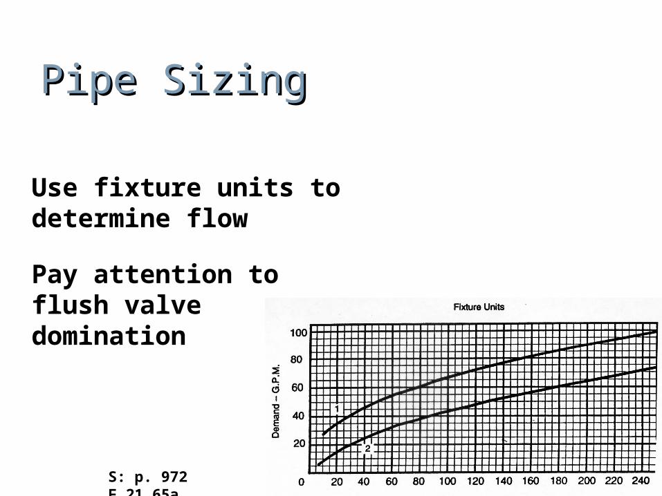
Use fixture units to determine flow
Pay attention to flush valve domination
S: p. 972 F.21.65a
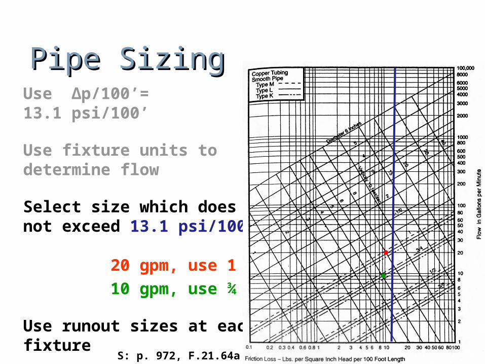
Pipe SizingPipe SizingUse Δp/100’= 13.1 psi/100’
Use fixture units to determine flow
Select size which does not exceed 13.1 psi/100’
20 gpm, use 1” 10 gpm, use ¾”
Use runout sizes at each fixture
S: p. 972, F.21.64a
Runout Runout Pipe SizingPipe Sizing
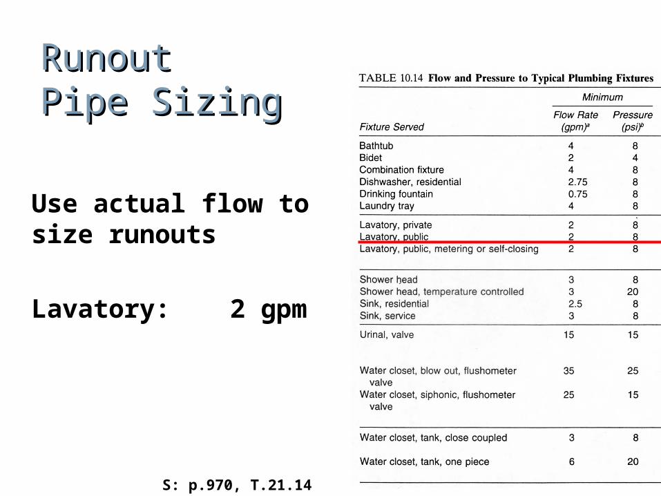
Use actual flow to size runouts
Lavatory: 2 gpm
S: p.970, T.21.14
Runout Runout Pipe SizingPipe Sizing
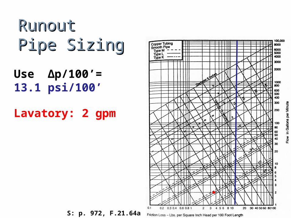
Use Δp/100’= 13.1 psi/100’
Lavatory: 2 gpm
S: p. 972, F.21.64a
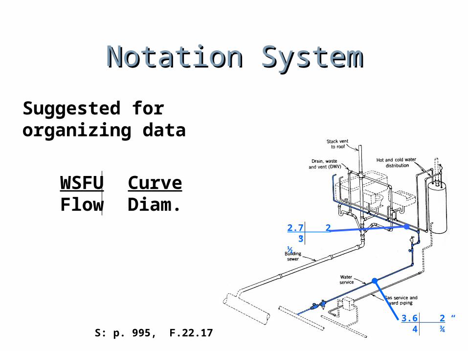
Notation SystemNotation System
Suggested for organizing data
WSFU CurveFlow Diam.
S: p. 995, F.22.17
3.6 2 4 ¾”
2.7 2 3 ½”