Embed Size (px)
Citation preview
Jefferson-Martin 230 kV Transmission Line Project D.6 GEOLOGY, SOILS, AND PALEONTOLOGY
D.6 Geology, Soils, and Paleontology Section D.6.1 provides a summary of existing geological, soil, and paleontological conditions present along the alignment of Pacific Gas and Electric Company’s (PG&E) proposed Jefferson-Martin 230 kV Transmission Line Project and associated geologic and seismic hazards. Descriptions of geologic and geologic hazards specific to segments of the transmission line are provided in Sections D.6.1.1 through D.6.1.4. Applicable regulations, plans, and standards are listed in Section D.6.2. Potential impacts and mitigation measures for the Proposed Project are presented in D.6.3; and alternatives are described and discussed in Sections D.6.4 through D.6.6. Mitigation monitoring, compliance, and reporting is discussed in Section D.6.7.
D.6.1 Environmental Setting for the Proposed Project
This section presents a discussion of the regional topography, geology, seismicity, soils, mineral and paleontological resources in the project area, followed in Section D.6.1.1 by a more specific discussion of each of these issues along the proposed alignment for each segment of the Proposed Project.
Baseline geologic information was collected from published and unpublished geologic, seismic, and geotechnical literature covering the Proposed Project and the surrounding area. The literature review was supplemented by a field reconnaissance of the proposed and alternative alignments. The literature review and field reconnaissance focused on the identification of specific geologic hazards and paleontologic resources.
The project alignment is located in the west-central portion of the Coast Ranges Geomorphic Province, which is characterized by a series of north-northwest trending ranges and valleys, few of which are continuous for more than 100 miles. The province extends from Santa Barbara County northward to the Oregon border (Norris and Webb, 1990) and varies in width from a few miles to 70 miles. In the project area the Coast Range is approximately 50 miles wide.
Topography
The proposed transmission line route traverses diverse topography ranging from the gently sloping floodplain of Colma Creek along the BART right of way (ROW) to moderate to steep slopes on San Bruno Mountain and the ridges east of the San Andreas Fault. Elevations along the proposed alignment range from about 15 feet at the Martin Substation to approximately 725 feet above mean sea level (msl) where the alignment crosses San Bruno Mountain along Guadalupe Canyon Parkway. Elevations were determined using TOPO software (TOPO, 2002).
Geology
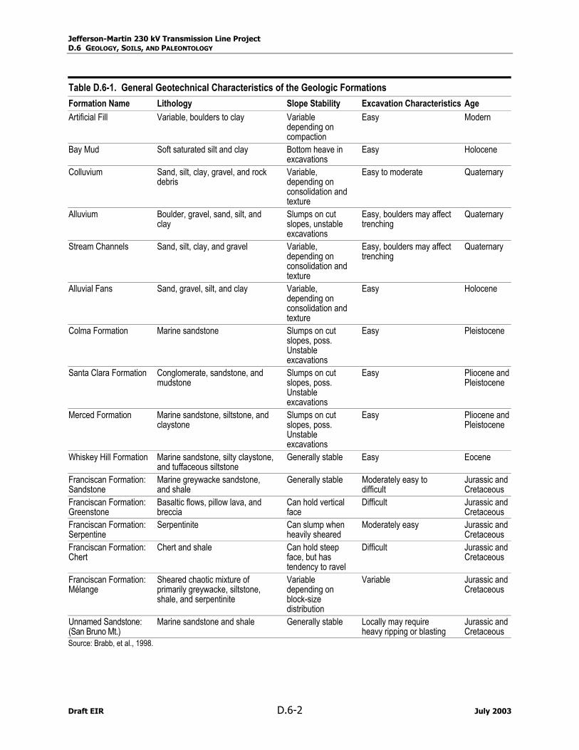
Geologic conditions anticipated to be encountered during construction of the Proposed Project are summarized in Table D.6-1. This table lists each geologic formation, a description of the formation's general rock type or lithology, the slope stability, excavation characteristics, and age of each formation along the proposed route.
July 2003 D.6-1 Draft EIR
Jefferson-Martin 230 kV Transmission Line Project D.6 GEOLOGY, SOILS, AND PALEONTOLOGY
Table D.6-1. General Geotechnical Characteristics of the Geologic Formations Formation Name Lithology Slope Stability Excavation Characteristics Age Artificial Fill Variable, boulders to clay Variable
depending on compaction
Easy Modern
Bay Mud Soft saturated silt and clay Bottom heave in excavations
Easy Holocene
Colluvium Sand, silt, clay, gravel, and rock debris
Variable, depending on consolidation and texture
Easy to moderate Quaternary
Alluvium Boulder, gravel, sand, silt, and clay
Slumps on cut slopes, unstable excavations
Easy, boulders may affect trenching
Quaternary
Stream Channels Sand, silt, clay, and gravel Variable, depending on consolidation and texture
Easy, boulders may affect trenching
Quaternary
Alluvial Fans Sand, gravel, silt, and clay Variable, depending on consolidation and texture
Easy Holocene
Colma Formation Marine sandstone Slumps on cut slopes, poss. Unstable excavations
Easy Pleistocene
Santa Clara Formation Conglomerate, sandstone, and mudstone
Slumps on cut slopes, poss. Unstable excavations
Easy Pliocene and Pleistocene
Merced Formation Marine sandstone, siltstone, and claystone
Slumps on cut slopes, poss. Unstable excavations
Easy Pliocene and Pleistocene
Whiskey Hill Formation Marine sandstone, silty claystone, and tuffaceous siltstone
Generally stable Easy Eocene
Franciscan Formation: Sandstone
Marine greywacke sandstone, and shale
Generally stable Moderately easy to difficult
Jurassic and Cretaceous
Franciscan Formation: Greenstone
Basaltic flows, pillow lava, and breccia
Can hold vertical face
Difficult Jurassic and Cretaceous
Franciscan Formation: Serpentine
Serpentinite Can slump when heavily sheared
Moderately easy Jurassic and Cretaceous
Franciscan Formation: Chert
Chert and shale Can hold steep face, but has tendency to ravel
Difficult Jurassic and Cretaceous
Franciscan Formation: Mélange
Sheared chaotic mixture of primarily greywacke, siltstone, shale, and serpentinite
Variable depending on block-size distribution
Variable Jurassic and Cretaceous
Unnamed Sandstone: (San Bruno Mt.)
Marine sandstone and shale Generally stable Locally may require heavy ripping or blasting
Jurassic and Cretaceous
Source: Brabb, et al., 1998.
Draft EIR D.6-2 July 2003
Jefferson-Martin 230 kV Transmission Line Project D.6 GEOLOGY, SOILS, AND PALEONTOLOGY
l
The geologic units exposed at the surface along the proposed alignment consist primarily of artificial fill, alluvium, colluvium, and stream channel deposits of Holocene and Quaternary age; marine sandstone, siltstone, and claystone of Pliocene and Pleistocene age; and Cretaceous and Tertiary age sandstone, shale, chert, greenstone, and serpentinite units of the Franciscan Group, an Unnamed Sandstone on San Bruno Mountain, and the Whiskey Hill Formation (Brabb, 1998). Holocene Bay Mud is not exposed at the surface along the project alignment but is thought to underlie the artificial fill along the San Francisco Bay margin and is expected to be encountered in excavations in the project area.
Artificial Fil
Artificial fill consists of loose to very well consolidated gravel, sand, silt, clay, rock fragments, organic matter, and man-made debris in various combinations. Thickness is variable and may exceed 30 meters in places. Some is compacted and quite firm, but fill made before 1965 is nearly always compacted and consists simply of dumped materials.
Bay Mud
Water-saturated estuarine mud, predominantly dark gray, green, and blue clay and silty clay underlying marshlands and tidal mud flats of San Francisco Bay. The mud also contains lenses of well-sorted, fine sand and silt, shelly layers (oysters), and peat. The mud interfingers with and grades into fine-grained deposits at the distal edge of alluvial fans. Mud varies in thickness from zero, at landward edge, to as much as 150 feet at the bay margin. Bay mud deposits are thought to underlie mapped artificial fill deposits at the mouth of Visitacion Valley near Martin Substation.
Stream Channel Deposits
Stream channel deposits in the project area consist of poorly to well-sorted sand, silt, silty sand, or sandy gravel with minor cobbles. Cobbles are more common in the mountainous valleys draining into San Andreas Lake and Upper and Lower Crystal Springs Reservoirs, and along San Mateo Creek. Many small stream channels are presently lined with concrete and diverted into artificially straightened channels which are lined with concrete or rip rap. This straightening is especially prevalent in the highly urbanized lower reaches of streams entering the estuary. The mapped distribution of stream channel deposits is controlled by the depiction of major creeks on the most recent United States Geologic Survey (USGS) 7.5-minute topographic maps. Only those deposits related to major creeks are mapped. In some places these deposits are under shallow water for some or all of the year, as a result of reservoir release and annual variation in rainfall.
Alluvium
Alluvium in the project area consists of unconsolidated gravel, sand, silt, and clay near streams and on the margins of San Andreas and Upper and Lower Crystal Springs Reservoirs. Alluvium may be encountered along the project alignment along the beds of former stream channels which have been straightened or diverted into underground pipes within the highly urbanized flatlands of the Colma Creek drainage. Alluvial deposits are generally less than 10 to 20 feet thick in most places.
Colluvium
Colluvium consists of loose to firm, friable, unsorted sand, silt, clay, gravel, rock debris, and organic material in varying proportions and is found along the western and northern slopes of San Bruno Mountain.
July 2003 D.6-3 Draft EIR
Jefferson-Martin 230 kV Transmission Line Project D.6 GEOLOGY, SOILS, AND PALEONTOLOGY
l
Alluvial Fan
Alluvial fan deposits are brown or tan, medium dense to dense, gravelly sand or sandy gravel that generally grades upward to sandy or silty clay. Near the distal fan edges, the deposits are typically brown, medium dense sand that fines upward to sandy or silty clay and interfinger with either alluvium or bay mud deposits.
Colma Formation
Yellowish-gray and gray, weathering to yellowish-orange and red-brown, friable to loose, fine- to medium-grained arkosic sand with subordinate amounts of gravel, silt, and clay. Total thickness in the project area is unknown, but may be as much as 200 feet.
Santa Clara Formation
The Santa Clara Formation is characterized as gray to red-brown poorly indurated conglomerate, sandstone, and mudstone in irregular and lenticular beds. Conglomerate consists mainly of subangular to subrounded cobbles in a sandy matrix but locally includes pebbles and boulders. Cobbles and pebbles are mainly chert, greenstone, and graywacke with some schist, serpentinite, and limestone. The Proposed Project alignment passes near but does not overlie this unit; however, portions of alterna-tive routes near the Jefferson Substation cross mapped areas of Santa Clara Formation.
Merced Formation
The Merced Formation consists of medium-gray weathering to yellowish gray and yellowish orange, medium- to very fine-grained, poorly indurated to friable sandstone, siltstone, and claystone, with some conglomerate lenses and a few friable beds of white volcanic ash. In many places sandstone is silty, clayey, or conglomeratic. Some of the conglomerate, especially where fossiliferous, is well cemented. Volcanic ash is in beds as much as 6 feet thick and consists largely of glass shards.
Whiskey Hil Formation
Eocene-age, light-gray to light brown coarse-grained arkosic sandstone, with light-gray to light brown silty claystone, glauconitic sandstone, and tuffaceous siltstone. Sandstone beds constitute about 30 percent of map unit. Tuffaceous and silty claystone beds are expansive. Locally, sandstone beds are well cemented with calcite. In places within this map unit, sandstone and claystone beds are chaotically disturbed.
Franciscan Group
The Franciscan Group consists of a complex assemblage of predominantly graywacke sandstone interbedded with lesser amounts of dark shale. Outcrops of serpentinite, submarine basalt (greenstone), limestone, chert, and metamorphic blue schist are also contained within the complex, usually bounded by faults, and often occurring in discontinuous blocks too small to depict on maps. Within the project area, the most common Franciscan unit is sheared rock, or mélange, predominantly consisting of serpentinite and shale with blocks of unsheared greywacke, chert, and greenstone. The dominant units mapped along the project alignment are described below.
Mélange (Sheared Rock). Chaotic mixture of all the Franciscan rock types, substantial portions of which have been sheared, but includes hard blocks of all other Franciscan rock types.
Draft EIR D.6-4 July 2003
Jefferson-Martin 230 kV Transmission Line Project D.6 GEOLOGY, SOILS, AND PALEONTOLOGY
Sandstone. Greenish-gray to buff, fine- to coarse-grained sandstone (graywacke), with interbedded siltstone and shale. Siltstone and shale interbeds constitute less than 20 percent of this unit, but in places form sequences as much as several tens of meters thick. In many places in the project area, shearing has obscured bedding relations; rock in which shale has been sheared to gouge constitutes about 10 percent of the unit. Gouge is concentrated in zones that are commonly less than 100 feet wide but in places may be as much as 500 feet wide.
Unnamed Sandstone of San Bruno Mountain. Dark-gray to yellowish-brown graywacke interbedded with shale, in approximately equal amounts. Unit resembles some Franciscan sandstone but the bedding is better developed herein. This unit is exposed in San Bruno Mountain, where it is about 3,250 feet thick. It probably represents a large, coherent block within the Franciscan Complex.
Serpentinite. Greenish-gray to bluish-green serpentine rock. Sheared serpentinite occurs in stringers and bands throughout the project area, enclosing variably abundant blocks of unsheared rock. Blocks are commonly less than 10 feet in diameter, but range in size from one inch to 20 feet; they consist of greenish-black serpentinite, schist, rodingite, ultramafic rock, and silica-carbonate rock, nearly all of which are too small to be shown at a reasonable map scale.
Greenstone. Dark-green to red altered basaltic rocks, including flows, pillow lavas, breccias, tuff breccias, tuffs, and minor related intrusive rocks, in unknown proportions. Unit includes some Franciscan chert and limestone bodies that are too small to map. Greenstone crops out in lenticular bodies varying in thickness from a few feet to many hundreds of feet.
Chert. White, green, red, and orange chert, in places interbedded with reddish-brown shale. Chert and shale commonly are rhythmically banded in thin layers, but chert also crops out in very thick layers. In San Carlos, chert has been altered along faults to tan- to light brown-colored clay. Chert and shale crop out in lenticular bodies as much as 250 feet thick; chert bodies are commonly associated with Franciscan greenstone.
Slope Stability
Important factors that affect the slope stability of an area include the steepness of the slope and the relative strength of the underlying rock material. The steeper the slope and/or the less strong the rock, the more likely the area is susceptible to landslides and slips. Such areas can be identified on maps showing the steepness of slopes (Graham and Pike, 1998) used in combination with a geologic map. Another indication of unstable slopes is the presence of old or recent landslides. The Landslide Folio (Wentworth, et al., 1997) shows areas where landslides exist.
The proposed alignment and the alternatives do not cross any areas identified as an existing landslide area or susceptible to landslides, with the exception of a few very steep areas on either side of the San Mateo Creek canyon near Crystal Springs Reservoir.
Faults and Seismicity
The seismicity of the project area is dominated by the northwest trending San Andreas Fault system (see Figure D.6-1). The San Andreas Fault system is responding to stress produced by the relative motions of the Pacific and North American Tectonic Plates. This stress is relieved by strain, predomi-nantly as right lateral strike slip faulting on the San Andreas and other related faults. The effects of this strain also include mountain building, basin development, deformation of Quaternary deposits, wide-spread regional uplift, and the generation of earthquakes (Wallace, 1990).
July 2003 D.6-5 Draft EIR
Jefferson-Martin 230 kV Transmission Line Project D.6 GEOLOGY, SOILS, AND PALEONTOLOGY
The Coast Ranges are characterized by numerous geologically young faults. These faults can be classi-fied as historically active, active, potentially active, or inactive, based on the following criteria (Hart, 1994):
• Faults that have generated earthquakes accompanied by surface rupture during historic time (approx-imately the last 200 years), and faults that exhibit seismic fault creep are defined as Historically Active.
• Faults that show geologic evidence of movement within Holocene time (approximately the last 11,000 years) are defined as Active.
• Faults that show geologic evidence of movement during the Quaternary (approximately the last 1.6 million years) are defined as Potentially Active.
• Faults that show direct geologic evidence of inactivity during all of Quaternary time or longer are classified as Inactive.
The most recent probability calculations by the USGS’s Earthquake Hazards Program for Northern California indicate a 62% probability of at least one magnitude 6.7 or greater earthquake on one of several active faults in the San Francisco Bay Area before 2032 (Working Group on California Earthquake Probabilities, 2003). A major quake could occur on any of four major fault zones. The zone with the highest probability is the Hayward/Rogers Creek fault zone with a 27% chance of a quake of magnitude greater than or equal to 6.7; the San Andreas Fault zone is ranked second with a 21% probability of a similar quake. The 62% is the combined probability for all four fault zones.
Since periodic earthquakes accompanied by surface displacement can be expected to continue in the study area through the lifetime of the Proposed Project, the effects of strong groundshaking and fault rupture are of primary concern to safe operation of the proposed transmission line and associated facilities.
Strong Groundshaking
The intensity of earthquake induced ground motions can be described using peak site accelerations, represented as a fraction of the accel-eration of gravity (g). The California Geological Survey’s Proba-bilistic Seismic Hazard Assessment Maps for the San Francisco quad-rangle were used to predict peak ground accelerations along the Proposed Project alignment. The Probabilistic Seismic Hazard Assessment Maps depict peak ground accelerations with a 10 percent probability of exceedance in 50 years. The results for the Proposed Project are presented in Table D.6-2.
Table D.6-2. Peak Ground Acceleration Proposed
Transmission Line Milepost
Peak Ground Acceleration
0.0 to 25.0 Greater than 0.7g
25.0 to 27.0 0.6 to 0.7g
Fault Rupture
Perhaps the most important single factor to be considered in the seismic design of transmission lines crossing active faults is the amount and type of potential ground surface displacement. The active San Andreas Fault is the most likely to rupture, other faults crossed by the project alignment include the Serra, San Bruno, and Hillside faults. Movement on the active San Andreas Fault was responsible for the 1906 San Francisco earthquake and exhibited as much as 20 feet of right lateral displacement (Lawson, 1908). Strike-slip earthquakes of magnitude 6.0 or greater are likely to be associated with surface fault rupture and offset (CGS, 1996).
Draft EIR D.6-6 July 2003

Jefferson-Martin 230 kV Transmission Line Project D.6 GEOLOGY, SOILS, AND PALEONTOLOGY
Figure D.6-1a. San Andreas Fault and Alquist-Priolo Earthquake Zone Near Jefferson Substation For security reasons this figure is not included in the online version of the report.
July 2003 D.6-7 Draft EIR
Jefferson-Martin 230 kV Transmission Line Project D.6 GEOLOGY, SOILS, AND PALEONTOLOGY
Figure D.6-1b. San Andreas Fault and Alquist-Priolo Earthquake Zone Near Proposed Transition Station For security reasons this figure is not included in the online version of the report.
Draft EIR D.6-8 July 2003
Jefferson-Martin 230 kV Transmission Line Project D.6 GEOLOGY, SOILS, AND PALEONTOLOGY
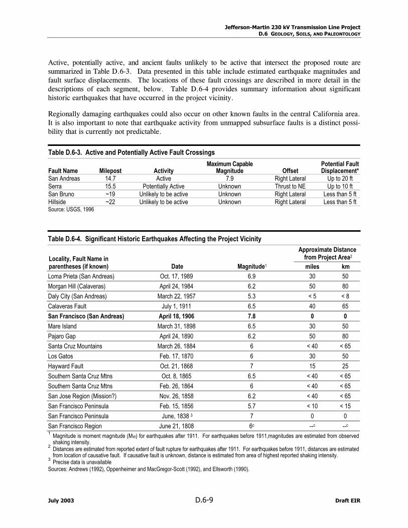
Active, potentially active, and ancient faults unlikely to be active that intersect the proposed route are summarized in Table D.6-3. Data presented in this table include estimated earthquake magnitudes and fault surface displacements. The locations of these fault crossings are described in more detail in the descriptions of each segment, below. Table D.6-4 provides summary information about significant historic earthquakes that have occurred in the project vicinity.
Regionally damaging earthquakes could also occur on other known faults in the central California area. It is also important to note that earthquake activity from unmapped subsurface faults is a distinct possi-bility that is currently not predictable.
Table D.6-3. Active and Potentially Active Fault Crossings
Fault Name Milepost Activity Maximum Capable
Magnitude Offset Potential Fault Displacement*
San Andreas 14.7 Active 7.9 Right Lateral Up to 20 ft Serra 15.5 Potentially Active Unknown Thrust to NE Up to 10 ft San Bruno ~19 Unlikely to be active Unknown Right Lateral Less than 5 ft Hillside ~22 Unlikely to be active Unknown Right Lateral Less than 5 ft Source: USGS, 1996
Table D.6-4. Significant Historic Earthquakes Affecting the Project Vicinity
Approximate Distance from Project Area2 Locality, Fault Name in
parentheses (if known) Date Magnitude1 miles km Loma Prieta (San Andreas) Oct. 17, 1989 6.9 30 50 Morgan Hill (Calaveras) April 24, 1984 6.2 50 80 Daly City (San Andreas) March 22, 1957 5.3 < 5 < 8 Calaveras Fault July 1, 1911 6.5 40 65 San Francisco (San Andreas) April 18, 1906 7.8 0 0 Mare Island March 31, 1898 6.5 30 50 Pajaro Gap April 24, 1890 6.2 50 80 Santa Cruz Mountains March 26, 1884 6 < 40 < 65 Los Gatos Feb. 17, 1870 6 30 50 Hayward Fault Oct. 21, 1868 7 15 25 Southern Santa Cruz Mtns Oct. 8, 1865 6.5 < 40 < 65 Southern Santa Cruz Mtns Feb. 26, 1864 6 < 40 < 65 San Jose Region (Mission?) Nov. 26, 1858 6.2 < 40 < 65 San Francisco Peninsula Feb. 15, 1856 5.7 < 10 < 15 San Francisco Peninsula June, 1838 3 7 0 0 San Francisco Region June 21, 1808 6c --c --c
1 Magnitude is moment magnitude (MW) for earthquakes after 1911. For earthquakes before 1911,magnitudes are estimated from observed shaking intensity.
2 Distances are estimated from reported extent of fault rupture for earthquakes after 1911. For earthquakes before 1911, distances are estimated from location of causative fault. If causative fault is unknown, distance is estimated from area of highest reported shaking intensity.
3 Precise data is unavailable Sources: Andrews (1992), Oppenheimer and MacGregor-Scott (1992), and Ellsworth (1990).
July 2003 D.6-9 Draft EIR
Jefferson-Martin 230 kV Transmission Line Project D.6 GEOLOGY, SOILS, AND PALEONTOLOGY
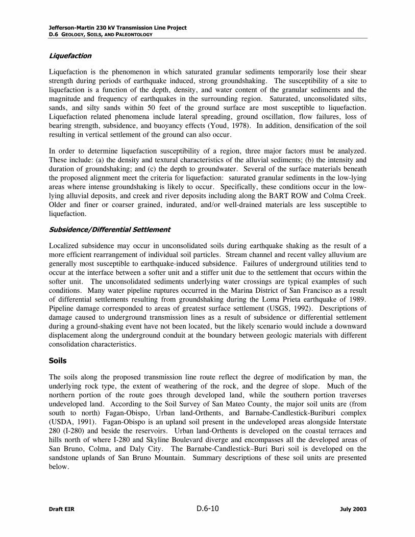
Liquefaction
Liquefaction is the phenomenon in which saturated granular sediments temporarily lose their shear strength during periods of earthquake induced, strong groundshaking. The susceptibility of a site to liquefaction is a function of the depth, density, and water content of the granular sediments and the magnitude and frequency of earthquakes in the surrounding region. Saturated, unconsolidated silts, sands, and silty sands within 50 feet of the ground surface are most susceptible to liquefaction. Liquefaction related phenomena include lateral spreading, ground oscillation, flow failures, loss of bearing strength, subsidence, and buoyancy effects (Youd, 1978). In addition, densification of the soil resulting in vertical settlement of the ground can also occur.
In order to determine liquefaction susceptibility of a region, three major factors must be analyzed. These include: (a) the density and textural characteristics of the alluvial sediments; (b) the intensity and duration of groundshaking; and (c) the depth to groundwater. Several of the surface materials beneath the proposed alignment meet the criteria for liquefaction: saturated granular sediments in the low-lying areas where intense groundshaking is likely to occur. Specifically, these conditions occur in the low-lying alluvial deposits, and creek and river deposits including along the BART ROW and Colma Creek. Older and finer or coarser grained, indurated, and/or well-drained materials are less susceptible to liquefaction.
Subsidence/Differential Settlement
Localized subsidence may occur in unconsolidated soils during earthquake shaking as the result of a more efficient rearrangement of individual soil particles. Stream channel and recent valley alluvium are generally most susceptible to earthquake-induced subsidence. Failures of underground utilities tend to occur at the interface between a softer unit and a stiffer unit due to the settlement that occurs within the softer unit. The unconsolidated sediments underlying water crossings are typical examples of such conditions. Many water pipeline ruptures occurred in the Marina District of San Francisco as a result of differential settlements resulting from groundshaking during the Loma Prieta earthquake of 1989. Pipeline damage corresponded to areas of greatest surface settlement (USGS, 1992). Descriptions of damage caused to underground transmission lines as a result of subsidence or differential settlement during a ground-shaking event have not been located, but the likely scenario would include a downward displacement along the underground conduit at the boundary between geologic materials with different consolidation characteristics.
Soils
The soils along the proposed transmission line route reflect the degree of modification by man, the underlying rock type, the extent of weathering of the rock, and the degree of slope. Much of the northern portion of the route goes through developed land, while the southern portion traverses undeveloped land. According to the Soil Survey of San Mateo County, the major soil units are (from south to north) Fagan-Obispo, Urban land-Orthents, and Barnabe-Candlestick-Buriburi complex (USDA, 1991). Fagan-Obispo is an upland soil present in the undeveloped areas alongside Interstate 280 (I-280) and beside the reservoirs. Urban land-Orthents is developed on the coastal terraces and hills north of where I-280 and Skyline Boulevard diverge and encompasses all the developed areas of San Bruno, Colma, and Daly City. The Barnabe-Candlestick–Buri Buri soil is developed on the sandstone uplands of San Bruno Mountain. Summary descriptions of these soil units are presented below.
Draft EIR D.6-10 July 2003
Jefferson-Martin 230 kV Transmission Line Project D.6 GEOLOGY, SOILS, AND PALEONTOLOGY
Fagan-Obispo (FO). These soils range from shallow to deep, on gently rolling to steep terrain. Soils are well drained and are developed on the variable rock types of the Franciscan Complex. Fagan soil is loamy and deep, and is underlain by sandstone and shale; deep accumulations may be susceptible to landsliding or slippage. Obispo soil is clayey and shallow, and is underlain by hard, serpentine rock. Obispo soils have a tendency to shrink/swell.
Urban Land–Orthents, Smoothed (UO). These soils are highly variable with respect to depth of development and steepness of slope on which they occur. The Urban land category includes generally well drained soils underlain by soft sandstone, whereas the Orthents, smoothed category comprises very shallow to very deep, well-drained, fine sandy loam over loam. Erosion hazard occurs where slopes are steep. Because of the high extent of modification of the surface soils, no engineering properties are reported for this soil type.
Barnabe-Candlestick-Buriburi complex (BCB). These soils range from very shallow to moderately deep, and from moderately to very steep well-drained soils underlain by hard sandstone of the Franciscan Complex. Candlestick soil, where thick, is susceptible to shallow landslides. Specific locations of Candlestick soils are not distinguished on the maps of the soil survey.
None of the soils are identified by the Soil Survey as suitable for construction materials.
Mineral Resources
No major mineral resources occur along the proposed or the alternative alignments. A few crushed rock quarries are mapped near the proposed alternative alignments. One quarry is located on the east side of San Andreas Lake near the southern end of the study area. This site appears to be close to the proposed alignment on the map, but is not visible on aerial photos. The map symbol may represent an old borrow pit used during the construction of the reservoir dam. A few crushed rock quarries are located on San Bruno Mountain, but none of them appear to be close enough to any of the proposed or alternative alignments so as to create an impact or be impacted by the project.
Paleontologic Resources
A discussion of the sensitivity of paleontologic resources is provided in Section D.6.3.1. In Northern California, fossils of land-dwelling vertebrates are considered significant. Two geologic units occur along the proposed alignment that meet the criteria of moderate to high sensitivity of paleontological resources, the Whiskey Hill Formation and the Colma Formation. The areas where these units occur are described in the following sections.
D.6.1.1 Jefferson Substation to Ralston Substation
Topography. The topography along the proposed route between the Jefferson and Ralston Substations is gently rolling hills that range from 350 feet to 680 feet in elevation.
Geology. The geologic units crossed by the alignment are mainly part of the Franciscan Complex. Franciscan rocks include large blocks of serpentine and sandstone. A large outcrop of serpentine is mapped from a few hundred feet north of the Jefferson Substation through Edgewood Park. Existing Towers 0/3 to 0/5 are founded in the serpentinite (serpentine rock). Towers 0/6 through 2/13 are founded in Franciscan mélange, a sheared and mixed unit containing numerous rock types. Towers 2/14 to 3/20 are located within the Tertiary Whiskey Hill formation, a softer sandstone unit that overlies the
July 2003 D.6-11 Draft EIR
Jefferson-Martin 230 kV Transmission Line Project D.6 GEOLOGY, SOILS, AND PALEONTOLOGY
Franciscan. Towers 3/21 to 4/26 are in Franciscan mélange again, and Tower 4/27 and the Ralston Substation are located in Franciscan serpentinite.
Slope Stability. Due to the rolling topography and lack of steep slopes, this route has no apparent risk from slope instability.
Faults and Seismicity. Jefferson Substation lies within an Alquist-Priolo Earthquake Hazard zone due to its proximity to the 1906 San Andreas Fault trace, but is not crossed by any trace of the San Andreas Fault. This part of the route would be subject to extreme groundshaking in the event of an earthquake on the San Andreas Fault. The peak ground acceleration could be higher than 70% gravity (g) (CDMG, 2002). Groundshaking due to earthquakes on other faults would be less severe in this area.
Soils. Jefferson Substation occupies Urban Land/Orthents (UO) soil, but immediately north of the substation, the alignment crosses mainly Fagan/Obispo (FO) soil. One small patch of UO occurs at the crossing of Highway 92. Soils are thin on the ridges and thick in the valleys and swales. Soil is extremely thin in areas where it is developed over serpentine rock.
Mineral Resources. No mineral resources occur near this section of the alignment.
Paleontology. Fossils are known to occur in the Whiskey Hill formation but significant fossils are not known from the Franciscan Complex.
D.6.1.2 Ralston Substation to Carolands Substation
Topography. The topography along the proposed route between the Ralston and Carolands Substations is gently rolling hills that range from 350 feet to 700 feet in elevation.
Geology. The geologic units that would be crossed by the alignment are mainly Franciscan Complex. Tower 4/27 at the Ralston Substation starts in serpentinite that continues to Tower 6/34. From Tower 6/35 and 6/35a to Tower 6/38, the route crosses mélange; then returns to serpentinite from Tower 7/39 to 8/51 at the Carolands Substation. The substation itself may be founded in deeply weathered serpentinite or mélange (it is unclear which is present).
Slope Stability. Due to the rolling topography and lack of steep slopes, few landslides occur along this route. None are mapped crossing the alignment. This route has no apparent risk from slope instability.
Faults and Seismicity. No faults cross this alignment of the Proposed Project. However, this part of the route will be subject to extreme groundshaking in the event of an earthquake on the San Andreas Fault. The peak ground acceleration could be higher than 70% g (CDMG, 2002). Groundshaking due to earthquakes on other faults would be less severe in this area.
Soils. Ralston Substation and most of the route occupies Fagan/Obispo soil. Urban Land/Orthents soil occurs where the alignment traverses developed areas.
Mineral Resources. No mineral resources occur near this section of the proposed alignment.
Paleontology. Significant fossils are not known to occur in the Franciscan Complex.
Draft EIR D.6-12 July 2003
Jefferson-Martin 230 kV Transmission Line Project D.6 GEOLOGY, SOILS, AND PALEONTOLOGY
D.6.1.3 Carolands Substation to Transition Station
Topography. The topography along the proposed route between the Carolands Substation and the proposed transition station is gently rolling ridge top ranging from about 300 feet to 710 feet in elevation except for San Mateo Creek Canyon which is narrow and steep-sided with the low elevation of 160 feet.
Geology. The geologic units crossed by the alignment are mainly the types of Franciscan Complex. Transmission Tower 8/51 at the Carolands Substation is in Franciscan serpentinite or mélange which continues to Tower 8/52. From Towers 8/53 to 9/60 the route crosses serpentinite, then crosses a patch of greenstone (hard basalt) at Tower 9/61, then returns to serpentinite from Towers 9/62 to 10/66. Greenstone is again present from Towers 10/67 and 10/68. Mélange is present from Towers 10/69 to 12/80. The stretch from Tower 12/81 to 13/86 crosses either Franciscan sandstone or a Franciscan with a thin covering of Merced Formation (a softer, younger sandstone). The northernmost part of this stretch, from Tower 13/87 to the proposed Transition Station, crosses Franciscan sandstone. Depending on the final location of the transition station, it may be founded in sandstone or heavily crushed and sheared fault gouge lying within the San Andreas Fault zone.
Slope Stability. Due to the rolling topography and lack of steep slopes, few landslides occur along this route. Very steep slopes occur on the sides of San Mateo Creek Canyon below Crystal Springs Dam. During a field investigation conducted for this project, a recent shallow landslip was observed below the existing tower on the north side of the canyon. The rock unit present on both sides of the canyon is Franciscan mélange, a sheared rock unit. New tower footings would need to be carefully placed to avoid areas of weak rock or to cause weakening of the existing slope.
Faults and Seismicity. The northern end of the alignment lies within the San Andreas Fault Zone. This part of the route will be subject to extreme groundshaking and possible ground rupture in the event of an earthquake on the San Andreas Fault. The peak ground acceleration could be higher than 70% g (CDMG, 2002). Groundshaking due to earthquakes on other faults would be less severe in the project area. Ground rupture of up to 20 feet could occur depending on the size of the earthquake and the location of the epicenter with respect to the Proposed Project.
Soils. This route would cross through more developed areas, as reflected in the soil designations. Urban UO soil occurs where the alignment traverses developed areas along neighborhoods, adjacent to the highway and through the golf course. Where the route parallels the San Andreas Reservoir, the soil is of the FO group.
Mineral Resources. No mineral resources occur near this section of the proposed alignment.
Paleontology. Fossils are known to occur in the Merced Formation, but significant fossils are not known from the Franciscan Complex.
D.6.1.4 Underground Segments
San Bruno Avenue
Topography. The topography along the proposed underground route between Skyline Boulevard and El Camino Real via San Bruno Avenue and to the BART ROW is gently sloping terrain from Buri Buri Ridge at about 480 feet to the base of the slope to about 20 feet in elevation.
July 2003 D.6-13 Draft EIR
Jefferson-Martin 230 kV Transmission Line Project D.6 GEOLOGY, SOILS, AND PALEONTOLOGY
Geology. The geologic units crossed by this underground segment include Franciscan sandstone (fs) from the proposed transition station part of the way down the hill. A thin covering of Merced Formation and artificial fill overlie the Franciscan soil just west of the I-280 crossing. The east side of I-280 is Colma formation with local areas of artificial fill.
Slope Stability. Due to the gently sloping topography, few landslides occur or would be expected to occur along this route.
Faults and Seismicity. This proposed segment crosses the San Andreas Fault at the Skyline-San Bruno intersection. The proposed transition station would be located within an Alquist-Priolo Earthquake Hazard zone and between several mapped traces of the fault. About a mile down the hill, just west of I-280, the alignment crosses the Serra Fault, a fault that is not classified as an Alquist-Priolo fault, but shows evidence of movement in the Late Quaternary (making it a potentially active fault). The peak ground acceleration along the route could be higher than 70% g (CDMG, 2002). Groundshaking due to earthquakes on other faults would be less severe in this area of the project.
Soils. This route crosses developed areas designated as having UO soil along neighborhoods and within the roads.
Mineral Resources. No mineral resources occur near this section of the proposed alignment.
Paleontology. Fossils are known to occur in both the Merced and Colma formations which may be encountered while trenching in the hill slope and lower hill slope portions of the proposed underground route. Fossils are known to occur in the Franciscan sandstone, but they are generally not deemed significant.
BART ROW
Topography. The topography along the proposed underground route in the BART ROW is nearly flat terrain ranging from 20 feet to 70 feet in elevation. The proposed alignment follows the BART ROW up the broad river valley that was made by Colma Creek.
Geology. The entire segment is in clean fill recently installed over the new BART extension. The BART tunnel is built into Colma Formation and recent alluvium.
Slope Stability. The segment crosses areas mapped as surficial deposits and is mostly flat. There is no risk of landslides or slope instability.
Faults and Seismicity. No faults cross the alignment of the proposed underground segment in the BART ROW. However, this part of the route will be subject to extreme groundshaking in the event of an earthquake on the San Andreas Fault. The peak ground acceleration could be as high as 60 to 70% g or higher in places (CDMG, 2002). Groundshaking due to earthquakes on other faults would be less severe in this area.
Soils. This portion of the underground route crosses developed areas designated as having UO soil.
Mineral Resources. No mineral resources occur near this section of the proposed underground alignment.
Paleontology. Fossils are known to occur in the Colma Formation; however, because the underground segment would be placed within disturbed BART ROW, no fossils would be encountered.
Draft EIR D.6-14 July 2003
Jefferson-Martin 230 kV Transmission Line Project D.6 GEOLOGY, SOILS, AND PALEONTOLOGY
Colma to Martin Substation
Topography. The topography along this portion of the proposed underground segment varies from 65 feet in elevation in the area of McLellan Drive and 15 feet in elevation at Martin Substation to 715 feet in elevation at the top of San Bruno Mountain.
Geology. The western portion of this segment to Guadalupe Canyon Parkway is entirely within Colma Formation as mapped, but because the Colma Formation may be thin along the hillside, the trench could be excavated into Franciscan sandstone below Colma Formation. Guadalupe Canyon Parkway is mapped as lying within Franciscan sandstone, but because the trench follows the roadway, excavations may only encounter disturbed material and fill. The final portion of this segment, near and at the Martin Substation, is through artificial fill.
Slope Stability. All route segments cross areas mapped as covered by thin surficial deposits (soil) with few landslides. San Bruno Mountain is composed of sturdy sandstone that is not susceptible to landsliding except in over-steepened areas. The route over San Bruno Mountain would follow Guadalupe Canyon Parkway and would not traverse any over-steepened areas.
Faults and Seismicity. No faults cross the alignment of this proposed underground segment. However, this part of the route will be subject to extreme groundshaking in the event of an earthquake on the San Andreas Fault. The peak ground acceleration could be as high as 60 to 70% g in the vicinity of Colma and South San Francisco; 50 to 60% g on San Bruno Mountain and at the Martin Substation (CDMG, 2002). Groundshaking due to earthquakes on other faults would be less severe in this area.
Soils. Soils along the majority of this segment, including near the south and north ends of the Guadalupe Canyon Parkway, are UO soils. The top of San Bruno Mountain is mapped as having Barnabe-Candlestick–Buri Buri (BCB) soil complex. The BCB soils are variously thin and thick depending on the local topography and depth of weathered sandstone bedrock.
Mineral Resources. Crushed rock quarries are present on San Bruno Mountain, though they are not within the ROW of the Guadalupe Canyon Parkway.
Paleontology. The western portion of this segment (Colma) is entirely within Colma Formation, which is known to contain fossils, but because the line would be installed within roadway ROWs where sediments are already disturbed, it would be less likely that undisturbed sediments would be encountered. However, if the trench were to penetrate undisturbed Colma Formation, there would be a slight chance of significant fossils being disturbed. The eastern segment, along the roadbed of Guadalupe Canyon Parkway, is not likely to contain undisturbed bedrock. However, if the trench penetrates undisturbed rock, there is a slight chance of disturbing fossils in the sandstone of San Bruno Mountain, though fossils in the Cretaceous-age marine sandstone are not likely to be significant.
D.6.2 Applicable Regulations, Plans, and Standards
Geologic resources and geotechnical hazards are governed primarily by local jurisdictions. The conservation elements and seismic safety elements of city and county general plans contain policies for the protection of geologic features and avoidance of hazards, but do not specifically address transmis-sion line construction projects. Local grading ordinances establish detailed procedures for pipeline con-struction, including trench backfill, compaction, and testing.
July 2003 D.6-15 Draft EIR
Jefferson-Martin 230 kV Transmission Line Project D.6 GEOLOGY, SOILS, AND PALEONTOLOGY
State. In California, the Alquist-Priolo Earthquake Fault Zoning Act of 1972 (formerly the Special Studies Zoning Act) regulates development and construction of buildings intended for human occupancy to avoid the hazard of surface fault rupture. While this Act does not specifically regulate pipelines, it does help define areas where fault rupture is most likely to occur. This Act groups faults into categories of active, potentially active, and inactive. Historic and Holocene age faults are considered active, Late Quaternary and Quaternary age faults are considered potentially active, and pre-Quaternary age faults are considered inactive. These classifications are qualified by the conditions that a fault must be shown to be "sufficiently active" and "well defined" by detailed site-specific geologic explorations in order to determine whether building setbacks should be established.
The California Building Code (CBC, 2001) is based on the 1997 Uniform Building Code, with the addition of more extensive structural seismic provisions. Chapter 16 of the CBC contains definitions of seismic sources and the procedure used to calculate seismic forces on structures. As the Proposed Project route lies within UBC Seismic Zone 4, provisions for design should follow the requirements of Chapter 16. Chapter 33 of the CBC contains requirements relevant to the construction of underground transmission lines. CCR Title 24, Section 3301.2 and 3301.3 et seq. contain the provisions requiring protection of the adjacent property during excavations and requires 10 days written notice and access to the excavation be given to the adjacent property owners. Relevant owners would include BART along which a large portion of the proposed underground segment is located.
Local. The safety elements of General Plans for the cities and the County along the proposed alignment contain policies for the avoidance of geologic hazards and/or the protection of unique geologic features. A survey of General Plans along the proposed alignment indicated that most municipalities require submittal of construction and operational safety plans for proposed construction in areas of identified geologic and seismic hazards for review and approval prior to issuance of permits. County and local grading ordinances establish detailed procedures for excavation and grading required for underground construction.
D.6.3 Environmental Impacts and Mitigation Measures for the Proposed Project
A wide range of potential impacts, including loss of mineral and paleontological resources, slope instability including landslides, debris flows and slope creep, and seismic hazards including surface fault rupture, strong groundshaking, liquefaction, and seismically induced landslides, was considered in this analysis. Each of these potential geologic, soils, and paleontologic impacts is discussed in the following sections.
D.6.3.1 Definition and Use of Significance Criteria
Geology
Geologic conditions were evaluated with respect to the impacts the project may have on the local geology, as well as the impact that specific geologic hazards may have upon the pipeline and its related facilities. The significance of these impacts was determined on the basis of National Environmental Policy Act (NEPA) and CEQA statutes, guidelines and appendices, thresholds of significance developed by local agencies, government codes and ordinances, and requirements stipulated by California Alquist-Priolo statutes. Significance criteria and methods of analysis were also based on standards set or expected by agencies for the evaluation of geologic hazards.
Draft EIR D.6-16 July 2003
Jefferson-Martin 230 kV Transmission Line Project D.6 GEOLOGY, SOILS, AND PALEONTOLOGY
Impact assessment was developed based on geologic and geotechnical engineering evaluation of the project. The assumptions and justification for site specific assessments are explained in the text.
Impacts of the project on the geologic environment would be considered significant if:
• Unique geologic features or geologic features of unusual scientific value for study or interpretation would be disturbed or otherwise adversely affected by the transmission line alignment and con-sequent construction activities
• Known mineral and/or energy resources would be rendered inaccessible by transmission line construction
• Geologic processes, such as landslides, could be triggered or accelerated by construction or disturbance of landforms
• Substantial alteration of topography would be required or could occur beyond that which would result from natural erosion and deposition.
Impacts of the following geologic hazards on the project would also be considered significant:
• High potential for ground rupture due to presence of an active earthquake fault at the transmission line route with attendant potential for damage to the transmission line or other project structures
• High potential for earthquake-induced groundshaking to cause liquefaction, settlement, lateral spreading and/or surface cracking along the route and probable attendant damage to the transmission line or other project structures
• Potential for failure of construction excavations due to the presence of loose saturated sand or soft clay.
Soils
Major topics considered for assessing the project soil impacts included the erosion potential, agri-cultural productivity, and the corrosive effects of the soil on the transmission line duct encasement.
The impact of the project on soils is considered significant if:
• Erosion could be triggered or accelerated so that successful revegetation would be impaired and/or siltation would cause significant impacts on water quality or aquatic habitats
• Erosion of native soils or poorly compacted backfill could increase to a rate that would expose the trans-mission line casing or undermine structural supports (see Section D.7, Hydrology and Water Resources).
• The productivity of prime agricultural land would be reduced by disruption, mixing, displacement, or compaction of soils
• Agricultural soils would be converted to non-agricultural use
The impact of natural soils on the transmission line project would be considered significant if:
• Corrosive soils would damage the transmission line casing
• Expansive soils would damage aboveground structures.
Paleontology
Determination of the “significance” of a fossil can only occur after a fossil has been found and identified by a qualified paleontologist. Until then, the actual significance is unknown. The most useful designation for
July 2003 D.6-17 Draft EIR
Jefferson-Martin 230 kV Transmission Line Project D.6 GEOLOGY, SOILS, AND PALEONTOLOGY
paleontological resources in an EIR document is the “sensitivity” of a particular geologic unit. Sensitivity refers to the likelihood of finding significant fossils within a geologic unit. In Northern California, fossils of land-dwelling vertebrates are considered significant. Such fossils are found in fluvial and lake deposits.
The following levels of sensitivity recognize the important relationship between fossils and the geologic formations within which they are preserved.
• High Sensitivity. High sensitivity is assigned to geologic formations known to contain paleontological localities with rare, well-preserved, and/or critical fossil materials for stratigraphic or paleoenvironmental interpretation, and fossils providing important information about the paleobiology and evolutionary history (phylogeny) of animal and plant groups. Generally speaking, highly sensitive formations are known to produce vertebrate fossil remains or are considered to have the potential to produce such remains.
• Moderate Sensitivity. Moderate sensitivity is assigned to geologic formations known to contain paleontological localities with moderately preserved, common elsewhere, or stratigraphically long-ranging fossil material. The moderate sensitivity category is also applied to geologic formations that are judged to have a strong, but unproven potential for producing important fossil remains (e.g., Pre-Holocene sedimentary rock units representing low to moderate energy, of marine to non-marine depositional settings).
• Low Sensitivity. Low sensitivity is assigned to geologic formations that, based on their relative youthful age and/or high-energy depositional history, are judged unlikely to produce important fossil remains. Typically, low sensitivity formations may produce invertebrate fossil remains in low abundance.
• Marginal Sensitivity. Marginal sensitivity is assigned to geologic formations that are composed either of pyroclastic volcanic rocks or metasedimentary rocks, but which nevertheless have a limited probability for producing fossil remains from certain sedimentary lithologies at localized outcrops.
• Zero Sensitivity. Zero sensitivity is assigned to geologic formations that are entirely plutonic (volcanic rocks formed beneath the earth's surface) in origin and therefore have no potential for producing fossil remains.
D.6.3.2 Applicant Proposed Measures
PG&E has committed to implementation of the Applicant Proposed Measures (APMs) presented in Table D.6-5 to reduce potential impacts. The CPUC will ensure that these APMs are implemented by monitoring their implementation concurrent with monitoring of adopted mitigation measures.
D.6.3.3 230 kV/60 kV Overhead Transmission Line
This segment of the proposed route lies parallel to the San Andreas Fault and within one mile of the fault trace. The northern end of the segment crosses over the surface trace of the 1906 rupture in two places. In the event of an earthquake along the San Andreas Fault adjacent to the project, this entire segment would be subject to severe groundshaking and near-field effects such as amplified ground motions in particular areas. In addition, the transmission towers in the vicinity of the fault crossings would be subject to the hazard of surface fault rupture, potentially causing damage or failure of tower structures.
Draft EIR D.6-18 July 2003
Jefferson-Martin 230 kV Transmission Line Project D.6 GEOLOGY, SOILS, AND PALEONTOLOGY
Table D.6-5. Applicant Proposed Measures – Geology, Soils, and Paleontology APM No. Measure 10.1 If fossils are encountered during construction, a qualified paleontologist will be contacted to examine the find and to deter-
mine its significance. If the find is deemed to have scientific value, the paleontologist and PG&E will devise a plan to either avoid impacts or to continue construction without disturbing the integrity of the find (e.g., by carefully excavating the material containing the resources). APM 10.1 is superseded by Mitigation Measure G-3a (see Impact G-3 discussion in Section D.6.3.3).
10.2 Overhead Transmission Lines. For overhead transmission lines, site-specific geotechnical investigations will be performed at proposed tower locations to evaluate the potential for fault surface rupture. Where significant potential for fault surface rupture exists, tower locations will be adjusted as possible. Incorporation of standard engineering practices as part of the Project will ensure that people or structures are not exposed to fault rupture hazards. Underground Transmission Lines. Site-specific geotechnical investigations will be performed at locations where under-ground portions of the proposed transmission line cross mapped fault zones and intersect individual fault traces. Where significant potential for fault surface rupture is identified, appropriate engineering measures, such as installing breakaway connections and strategically locating splice boxes outside of the fault zone, will be implemented to protect sensitive equipment and limit the extent of potential repairs. Appropriate operation and maintenance measures will be implemented to prepare for potential fault-rupture scenarios and facilitate timely repair of facilities, if necessary. Preparation measures may include storage and maintenance of spare parts and equipment that may be needed to repair or temporarily bypass portions of the transmission line damaged as a result of fault surface rupture. Spare parts and equipment will be stored at the transition station or nearby PG&E facilities. Overhead-Underground Transition Station. A geotechnical investigation will be performed at the proposed overhead-underground transition station location to identify primary and subsidiary traces of the San Andreas Fault. Critical tran-sition station facilities, including transmission-line support structures, the overhead-underground transition structure, and the control building, will not be sited over active or potentially active traces of the fault. To the extent feasible, station structures will be designed to accommodate anticipated displacement and distortion of the ground surface during a major earthquake along the San Andreas Fault zone. As with design of underground transmission lines, transition station facilities will be designed for ductility and strength using reinforced components and flexible connections. Overhead transmission-line spans will be designed to accommodate potential fault displacement between support structures.
Source: PG&E, 2002.
Jefferson Substation to Ralston Substation
During the review of the geologic conditions along the overhead alignment, no evidence was found of especially problematic soil conditions. However, the Proponent’s Environmental Assessment (PEA) describes the possible presence of soft or loose soils, and compressible soils; therefore, Impacts G-1 and G-2 are identified below. Other impacts are also defined.
Impact G-1: Soft or Loose Soils Along Alignment May Affect Tower Foundations and Footings, Excavation Stability, and Access to Construction Areas
Loose or saturated sands and soft clays present along the proposed alignment may pose difficulties in excavating for pole or tower foundations, in trenching during construction of underground facilities, and in access to project sites during construction. Mitigation Measure G-1a described below is recommended to reduce potential impacts associated with soft or loose soils to less than significant levels (Class II).
Mitigation Measure for Impact G-1
G-1a Perform Geotechnical Studies. The Applicant shall perform design-level geotechnical studies to identify areas of soft or loose soils along the alignment where they may affect tower footing excavation stability and/or access roads. Where soft or loose soils are found, Best Management Practices (BMPs) shall be followed for avoidance, improvement, or replacement of affected soil
July 2003 D.6-19 Draft EIR
Jefferson-Martin 230 kV Transmission Line Project D.6 GEOLOGY, SOILS, AND PALEONTOLOGY
areas. BMPs shall be identified and provided to the CPUC and SFPUC for review and approval at least 60 days before construction.
Impact G-2: Excavation, Grading, or Fill Placement During Construction Activities Could Cause Slope Instability
Destabilization of natural or constructed slopes could occur as a result of construction activities due to excavation, grading, or fill operations. Excavation operations associated with pole foundation construc-tion could result in unstable excavation slopes, caving, and displacement of the adjacent ground surface. This potential hazard would be mitigated to less than significant levels (Class II) through the implementation of Mitigation Measure G-2a, described below.
Mitigation Measure for Impact G-2
G-2a Protect against slope instability. Appropriate support and protection measures shall be implemented to maintain the stability of excavations and protect surrounding structures and utilities to limit ground deformation. Design-level geotechnical investigations shall be performed to evaluate subsurface conditions, identify potential hazards, and provide information for development of excavation plans and procedures. Appropriate construction methods and procedures, in accordance with State and federal health and safety codes, shall be followed to protect the safety of workers and the public during trenching and excavation operations. PG&E shall document compliance with this measure prior to the start of construction by submitting a report to the CPUC for review and approval; the report shall document the investigations and detail the specific support and protection measures that will be implemented.
Impact G-3: Paleontologic Resources May Be Destroyed by Construction Activities
Some fossil-bearing geologic formations are located in the project area. Fossils are particularly common in the Merced formation, and a little less common in the Colma and Whiskey Hill formations. PG&E has recommended APM 10.1, which requires the construction contractor to contact a qualified paleontologist to assess the significance of a resource if fossils are encountered during construction. To strengthen the intent of APM 10.1, and to ensure that impacts to paleontological resources are mitigated to less than significant levels (Class II), Mitigation Measure G-3a is recommended. Measure G-3a supersedes APM 10.1.
Mitigation Measure for Impact G-3
G-3a Consult a Paleontologist. Prior to construction, a qualified paleontologist shall be consulted regarding the likelihood of encountering significant fossils along the proposed alignment. The definition of a “qualified paleontologist” is provided by the Society of Vertebrate Paleontologists (SVP, 1999). If the paleontologist determines fossils may be present, a paleontologic monitor shall be present at each excavation that penetrates potentially fossiliferous undisturbed native soil or rock (not fill or Franciscan rock). Any fossils that are found shall be prepared for curation and donated to a public museum such as the Museum of Paleontology at the University of California at Berkeley. PG&E shall document compliance with this measure prior to the start of construction; a report documenting the likelihood of encountering significant fossils shall be provided to the CPUC for review and approval.
Draft EIR D.6-20 July 2003
Jefferson-Martin 230 kV Transmission Line Project D.6 GEOLOGY, SOILS, AND PALEONTOLOGY
Impact G-4: Naturally Occurring Asbestos Fibers May Be Encountered and Become Airborne Through Construction Activities
The Proposed Project alignment traverses mapped areas of Franciscan serpentinite rock which is known to contain naturally occurring chrysotile asbestos minerals in varying abundance. Serpentinite rock is also a constituent of Franciscan mélange. Though all serpentinite rocks may not contain sufficient quantities of asbestos to create a hazardous condition, excavation and grading activities could potentially cause the airborne transport of chrysotile asbestos fibers. Mitigation Measure A-3a (see Air Quality, Section D.10.3.1), which requires the preparation of an Asbestos Dust Mitigation Plan per the requirements of Title 17 of the California Code of Regulations, would reduce potential impacts associated with naturally occurring asbestos to levels that are less than significant (Class II).
Mitigation Measure for Impact G-4
Implementation of Air Quality Mitigation Measure A-3a would ensure that impacts associated with naturally occurring asbestos fibers becoming airborne would be reduced to less than significant levels.
Impact G-5: Strong Groundshaking from Local and Regional Seismic Sources
This portion of the proposed route would not cross any active trace of the San Andreas Fault, though it lies very close. Severe groundshaking should be expected in the event of an earthquake on the fault in this area. The alignment is also subject to groundshaking from any of several major, active faults in the region. While the shaking would be less severe from an earthquake that originates farther from the alignment, the effects, particularly on the ridgelines, could be damaging to project structures.
It is likely that the project facilities would be subjected to at least one moderate or larger earthquake occurring close enough to produce strong groundshaking in the project area. Estimated horizontal peak ground acceleration (PGA) experienced by project facilities would range upwards from approximately 0.6 g for a maximum capable earthquake on the San Andreas Fault. To reduce potential impacts to less than significant levels (Class II), Mitigation Measure G-5a is recommended, which requires incorporation of standard engineering practices as part of the project, to ensure that people or structures are not exposed to hazards associated with strong seismic groundshaking.
Mitigation Measure for Impact G-5
G-5a Reduce Effects of Groundshaking. The Applicant shall perform design-level geotechnical inves-tigations including site-specific seismic analyses to evaluate the peak ground accelerations for design of project components. The Applicant shall follow the Institute of Electrical and Electronics Engineers (IEEE) 693 “Recommended Practices for Seismic Design of Substations” which has specific requirements to mitigate past substation equipment damage. These design guidelines shall be implemented during construction of substation modifications and transition station construction. Substation and transition station control buildings shall be designed in accordance with the Uniform Building Code for sites in Seismic Zone 4 with near-field factors. Compliance with this measure shall be documented to the CPUC at least 60 days before construction.
Impact G-6: Seismically Induced Ground Failures Including Liquefaction, Lateral Spreading, Seismic Slope Instability, and Ground-Cracking
Seismically induced ground failure includes liquefaction, lateral spreading, seismic slope instability (landslide) and ground-cracking. Liquefaction occurs in low-lying areas where saturated noncohesive
July 2003 D.6-21 Draft EIR
Jefferson-Martin 230 kV Transmission Line Project D.6 GEOLOGY, SOILS, AND PALEONTOLOGY
sediments are found. Lateral spreading occurs along waterfronts or canals where non-cohesive soils could move out along a free-face. Slope instability and ground-cracking can occur anywhere, but is generally concentrated on hilltops, ridgelines, or very close to an active trace of the fault.
As much of the this portion of the overhead segment is located along hillsides or ridgelines, the possibility of seismic-induced ground failure in the form of slope instability or ground-cracking is high. Mitigation Measure G-6a below would reduce potentially significant impacts for all potential instances of ground failure along the project to less than significant levels (Class II).
Mitigation Measure for Impact G-6
G-6a Geotechnical Investigations for Liquefaction and Slope Instability. Since seismically induced ground failure has the potential to damage or destroy project components, the Applicant shall perform design-level geotechnical investigations to assess the potential for liquefaction, lateral spreading, seismic slope instability, and ground-cracking hazards to affect the approved project and all associated facilities. Where these hazards are found to exist, appropriate engineering design and construction measures shall be incorporated into the project designs. Appropriate measures could include construction of pile foundations, ground improve-ment of liquefiable zones, installation of flexible bus connections, and incorporation of slack in underground cables to allow ground deformations without damage to structures. PG&E shall submit a report of the required investigations to the CPUC for review and approval at least 60 days before construction.
Ralston Substation to Carolands Substation
No evidence of especially problematic soil conditions, slope instability, fault rupture, or paleontologic resources has been identified along this portion of the route. The following previously identified Class II impacts and mitigation measures may affect this portion of the overhead segment: Impact G-2 (slope instability) would be mitigated by Mitigation Measure G-2a; Impact G-3 (destruction of paleontologic resources) would be mitigated by Mitigation Measure G-3a; Impact G-4 (naturally occurring asbestos fibers) would be mitigated by Mitigation Measure A-3a; Impact G-5 (strong groundshaking) would be mitigated by Mitigation Measure G-5a; and Impact G-6 (seismically induced ground failures) would be mitigated by Mitigation Measure G-6a. In addition, Impact G-7 is applicable to this portion of the overhead route segment.
Impact G-7: Slope Instability Including Landslides, Earth Flows, and Debris Flows
Slope instability including landslides, earth flows, and debris flows has the potential to undermine foundations, cause distortion and distress to overlying structures, and displace or destroy project components. The area where landslides would be most likely to occur is the steep sides of San Mateo Creek Canyon where towers are proposed fairly close to the steep canyon sides. Impacts associated with slope instability would be mitigated to less than significant levels (Class II) with implementation of Mitigation Measure G-7a, below.
Mitigation Measure for Impact G-7
G-7a Geotechnical Surveys for Landslides. The Applicant shall perform design-level geotechnical surveys to evaluate the potential for unstable slopes, landslides, earth flows, and debris flows along the approved transmission line route and in the vicinity of other project facilities. Based on these surveys, approved project facilities shall be located away from very steep hillsides,
Draft EIR D.6-22 July 2003
Jefferson-Martin 230 kV Transmission Line Project D.6 GEOLOGY, SOILS, AND PALEONTOLOGY
debris-flow source areas, the mouths of steep sidehill drainages, and the mouths of canyons that drain steep terrain. A report documenting these surveys shall be submitted to the CPUC at least 60 days before construction.
Carolands Substation to Transition Station
This portion of the overhead line route would cross the steep-sided San Mateo Creek Canyon. The fol-lowing previously identified Class II impacts and mitigation measures may affect this portion of the overhead segment: Impact G-2 (slope instability) would be mitigated by Mitigation Measure G-2a; Impact G-3 (destruction of paleontologic resources) would be mitigated by Mitigation Measure G-3a; Impact G-4 (naturally occurring asbestos fibers) would be mitigated by Mitigation Measure A-3a; Impact G-5 (strong groundshaking) would be mitigated by Mitigation Measure G-5a; and Impact G-6 (seismically induced ground failures) would be mitigated by Mitigation Measure G-6a.
In addition, the following impact is applicable to this portion of the overhead line.
Impact G-8: Surface Fault Rupture at Crossings of Active and Potentially Active Fault Traces
Project facilities would be subject to hazards of surface fault rupture at crossings of active traces of the San Andreas Fault between MP 14.1 and 14.9 along the proposed route. Hazards would not be as great where the proposed alignment crosses traces of potentially active faults, such as Serra Fault along San Bruno Avenue, the Cañada Trace of San Andreas Fault, or the unnamed fault trace near the Jefferson Substation. Fault crossings where multiple feet of displacement are expected along active faults are best crossed as overhead lines with towers placed well outside the fault zone to allow for the flex in the cables to absorb offset. APM 10.2 requires geotechnical investigations for surface rupture potential to be conducted for proposed tower locations and to adjust tower locations if possible where surface rupture potential exist. In addition to APM 10.2, Mitigation Measure G-8a is recommended for overhead crossings to minimize the length of transmission line within fault zones. Impacts associated with overhead active fault crossings can be mitigated to less than significant levels (Class II) because they are able to distribute fault displacements over a comparatively long span.
Mitigation Measure for Impact G-8
G-8a Minimize Project Structures Within Active Fault Zone. Any fault crossing (overhead or underground) shall be made as close to perpendicular to the fault as possible to make the segment cross the shortest distance within an active fault zone. For crossings of active faults with overhead transmission lines, the towers shall be placed as far as feasible outside the area of mapped fault traces. Compliance with this measure shall be documented to the CPUC in a report submitted at least 60 days prior to the start of construction.
D.6.3.4 Transition Station
The proposed transition station would be located at the intersection of San Bruno and Skyline Boulevard on a Caltrans-owned vacant parcel. In addition to roadwork and grading, the station would have an 8-foot-high masonry wall, enclosing the equipment, a control building and an underground vault. The control building would be enclosed by another masonry wall, approximately 10 feet by 10 feet by 13 feet. The outside dimensions of the underground vault would be about 24 feet by 10 feet by 10 feet.
July 2003 D.6-23 Draft EIR
Jefferson-Martin 230 kV Transmission Line Project D.6 GEOLOGY, SOILS, AND PALEONTOLOGY
The proposed transition station site is located immediately adjacent to two active traces of the San Andreas Fault. APM 10.2 requires that to the extent feasible, the station structures be designed to accommodate anticipated displacement and distortion associated with fault rupture. However, because of the possible large offsets of up to 20 feet (the west side of the fault would move north relative to the east side) that could occur along these active traces, structures and equipment associated with the proposed transition station would unavoidably be susceptible to impacts from surface fault rupture (Impact G-8). Fault rupture impacts to the proposed transition station would be significant and not mitigable to a level that is less than significant (Class I).
Potentially significant impacts that are mitigable to less than significant levels (Class II) at the transition station include Impact G-5 (strong groundshaking), mitigated with Mitigation Measure G-5a, and Impact G-6 (seismically induced ground failures), mitigated with implementation of Mitigation Measure G-6a.
D.6.3.5 230 kV Underground Transmission Line
San Bruno Avenue
This portion of the proposed underground route traverses areas where Merced and Colma formations are present. Impact G-3 (destruction of non-renewable paleontologic resources) would be mitigated to less than significant levels (Class II) with implementation of Mitigation Measure G-3a. In addition, Impact G-5 (strong groundshaking from local and regional seismic sources) and Impact G-6 (seismically induced ground failures) would be mitigated to less than significant levels with implementation of Mitigation Measures G-5a and G-6a, respectively.
Two separate faults exist along this portion of the proposed underground route: traces of the active San Andreas Fault along the first 0.2-mile portion of the underground segment (i.e., from MP 14.7 to 14.9) and the potentially active Serra Fault along San Bruno Avenue. Potentially significant impacts to the proposed underground line between the transition station and the BART ROW include possible fault rupture caused by movement along active traces of the San Andreas Fault and the potentially active Serra Fault. APM 10.2 requires preparation of geotechnical investigations at locations where under-ground portions of the proposed transmission line cross mapped fault zones for fault surface rupture and requires engineering measures, such as installing breakaway connections and strategically locating splice boxes outside of the fault zone. However, Impact G-8 (fault rupture at crossings of active and potentially active fault traces) would be significant and unavoidable at the active San Andreas Fault trace crossings near the transition station (Class I) and would be mitigated to less than significant levels (Class II) with implementation of Mitigation Measure G-8a at the Serra Fault crossing. Although the San Andreas Fault trace crossings would be significant and unmitigable impacts, Mitigation Measure G-8a is recommended to reduce impacts to the maximum extent feasible.
BART ROW
Because the entire route that follows the BART ROW would be placed within the clean, engineered fill over the BART tunnel, it is unlikely that any geologic, soil, or paleontologic issues would be encountered except for seismically induced groundshaking. Impact G-5 (strong groundshaking from local and regional seismic sources) would be mitigated to less than significant levels (Class II) with implementation of Mitigation Measure G-5a.
Draft EIR D.6-24 July 2003
Jefferson-Martin 230 kV Transmission Line Project D.6 GEOLOGY, SOILS, AND PALEONTOLOGY
Colma to Martin Substation
The following previously identified Class II impacts and mitigation measures would also be applicable to this segment of the proposed underground line:
• Impact G-3 (destruction of non-renewable paleontologic resources) would be mitigated with Mitigation Measure G-3a
• Impact G-5 (strong groundshaking from local and regional seismic sources) would be mitigated with Mitigation Measure G-5a)
• Impact G-6 (seismically induced ground failures) would be mitigated with implementation of Mitigation Measure G-6a.
In addition, the following impacts (G-9 through G-11) and mitigation measures (where applicable) apply to this underground segment of the proposed route.
Impact G-9: Expansive, Soft, Loose and/or Compressible Soils
Problematic soils can cause construction and maintenance hazards. Expansive-soil, or shrink-swell behavior is a condition in which clay-rich soils react to changes in moisture content by expanding or contracting. Several of the natural soil types identified within this portion of the project area have moderate to high clay contents and many have moderate to high shrink-swell potential. Expansive soils may cause differ-ential and cyclical foundation movements that can cause damage and/or distress to structures and equipment. Potential operation impacts from loose sands, soft clays, and other potentially compressible soils include excessive settlement, low foundation-bearing capacity, and limitation of year-round access to project facilities. Implementation of Mitigation Measure G-9a, below, would reduce potential impacts to less than significant levels (Class II).
Mitigation Measure for Impact G-9
G-9a Implement Standard Engineering Methods for Problematic Soils. The Applicant shall perform design-level geotechnical studies to identify areas with potentially problematic soils and develop appropriate design features, including excavation of potentially problematic soils during construction and replacement with engineered backfill, ground-treatment processes, direction of surface water and drainage away from expansive foundation soils. Study results and proposed solutions shall be provided to the CPUC for review and approval at least 60 days before construction.
Impact G-10: Project May Impact Access to Mineral Resources
The only economically viable mineral resources located along or adjacent to the Proposed Project alignment are on the west side of San Bruno Mountain. The project alignment in this area lies exclusively within paved roadways, and are therefore excluded from mapped resource sectors. Project construction would not block access to existing quarry operations, therefore potential impacts to mineral resources are considered to be less than significant (Class III) and mitigation measures are not required.
Impact G-11: Corrosive Soils
Corrosive subsurface soils may exist in the area of the proposed underground route along Bayshore Boulevard where Bay Mud is present beneath the road fill. Corrosive soils could have a detrimental effect on concrete and metals. Depending on the degree of corrosivity of subsurface soils, concrete and
July 2003 D.6-25 Draft EIR
Jefferson-Martin 230 kV Transmission Line Project D.6 GEOLOGY, SOILS, AND PALEONTOLOGY
reinforcing steel in concrete structures and bare-metal structures exposed to these soils could deteriorate, eventually leading to structural failures. Implementation of Mitigation Measure G-11a would reduce potential impacts from corrosive soils to less than significant levels (Class II).
Mitigation Measure for Impact G-11
G-11a Implement Standard Engineering Methods for Corrosive Soils. The Applicant shall perform design-level geotechnical studies to identify the presence, if any, of potentially detrimental soil chemicals, such as chlorides and sulfates. Appropriate design measures for protection of rein-forcement, concrete, and metal-structural components against corrosion shall be utilized, such as use of corrosion-resistant materials and coatings, increased thickness of project components exposed to potentially corrosive conditions, and use of passive and/or active cathodic protection systems. Study results and proposed solutions shall be provided to the CPUC for review and approval at least 60 days before construction.
D.6.3.6 Substations, Switchyard, and Taps
Jefferson Substation
Jefferson Substation is located east of I-280 and is accessed by Cañada Road. Work necessary to accommodate the Proposed Project includes the relocation and addition of transmission poles and equipment. Rearrangement of new and existing equipment within the substation would require modifi-cation to the existing fence line and perimeter road within the existing substation boundaries. There are no fault crossings at the substation; the primary rock type is Franciscan sandstone.
Soils at the substation have moderate to high shrink-swell potential. Potentially significant impacts associated with shrink-swell potential soils (Impact G-9) would be mitigated to less than significant levels (Class II) with implementation of Mitigation Measure G-9a. The substation modifications would be subject to extreme groundshaking in the event of an earthquake on the San Andreas Fault. Potentially significant impacts associated with strong groundshaking (Impact G-5) would be mitigated to less than significant levels (Class II) with implementation of Mitigation Measure G-5a.
Ralston Substation
Ralston Substation is northeast of the I-280 and State Route 92 (SR 92). Existing lattice steel structures would be replaced by four new dead-end structures. Outside the substation fence, two new H-frame structures would be added to bring the line under the 230 kV circuit. A new lattice steel tower (Tower 5/27) would replace the existing lattice steel and wood pole tap structures. The station ground and conduit system would be modified and expanded within the existing substation footprint. There are no fault crossings at the substation; the primary rock type is Franciscan serpentinite beneath any fill that has previously been brought in for the substation.
Soils have moderate to high shrink-swell potential. Potentially significant impacts associated with soils with shrink-swell potential (Impact G-9) would be mitigated to less than significant levels (Class II) with implementation of Mitigation Measure G-9a. Impacts associated with excavations within asbestos-containing serpentine rock (Impact G-4) would be mitigated to less than significant levels (Class II) with implementation of Mitigation Measure A-3a. The substation modifications would be subject to extreme groundshaking in the event of an earthquake on the San Andreas Fault. Potentially significant impacts associated with strong groundshaking (Impact G-5) would be mitigated to less than significant levels (Class II) with implementation of Mitigation Measure G-5a.
Draft EIR D.6-26 July 2003
Jefferson-Martin 230 kV Transmission Line Project D.6 GEOLOGY, SOILS, AND PALEONTOLOGY
Hillsdale Junction Switchyard
The Hillsdale Junction Switchyard is located at MP 6.4, east of I-280. Bus and breaker modification would occur within the existing substation fence line. A new, single-circuit tubular steel pole (no tower number) would be installed outside and to the west of the existing switchyard footprint, north of new Tower 6/35. Hillsdale Junction is situated at the top of the ridge just south of the steep-sided San Mateo Canyon. There are no fault crossings at the substation and the primary rock type is Franciscan sheared rock (mélange) beneath any fill that has previously been brought in for the switchyard.
Soils have moderate to high shrink-swell potential. Potentially significant impacts associated with soils with shrink-swell potential (Impact G-9) would be mitigated to less than significant levels (Class II) with implementation of Mitigation Measure G-9a. Impacts associated with excavations within asbestos-containing serpentine rock (Impact G-4) would be mitigated to less than significant levels (Class II) with implementation of Mitigation Measure A-3a. The substation modifications would be subject to extreme groundshaking in the event of an earthquake on the San Andreas Fault. Potentially significant impacts associated with strong groundshaking (Impact G-5) would be mitigated to less than significant levels (Class II) with implementation of Mitigation Measure G-5a.
Carolands Substation
The Carolands Substation is located at MP 8.8, east of Skyline Road. There are no fault crossings at the substation and the primary rock type is Franciscan sheared rock (mélange) beneath any fill that has previously been brought in for the substation.
Soils have moderate to high shrink-swell potential. Potentially significant impacts associated with soils with shrink-swell potential (Impact G-9) would be mitigated to less than significant levels (Class II) with implementation of Mitigation Measure G-9a. Impacts associated with excavations within asbestos-containing serpentine rock (Impact G-4) would be mitigated to less than significant levels (Class II) with implementation of Mitigation Measure A-3a.
Martin Substation
The Martin Substation is located to the southwest of the intersection of Bayshore Boulevard and Geneva Avenue. Relocation of fence, roadway, existing wood poles, and tubular steel poles near the southern perimeter of the substation is proposed to expand the existing yard. There are no fault crossings at the substation and the primary rock type is Quaternary-age alluvial fan deposits beneath any fill that has previously brought in for the substation.
Soils at Martin Substation may be susceptible to ground failure during a major earthquake and have indeterminate shrink-swell potential. Impacts associated with seismic induced ground failure (Impact G-6) would be mitigated to less than significant levels (Class II) with implementation of Mitigation Measure G-6a, and impacts associated with shrink-swell hazard (Impact G-9) would be mitigated to less than significant levels (Class II) with implementation of Mitigation Measure G-9a. In addition, corrosive soils may be present beneath the fill at the substation. This impact (Impact G-11) would be mitigated to less than significant levels (Class II) with implementation of Mitigation Measure G-11a.
July 2003 D.6-27 Draft EIR
Jefferson-Martin 230 kV Transmission Line Project D.6 GEOLOGY, SOILS, AND PALEONTOLOGY
San Mateo and Monta Vista Substations
Monta Vista Substation. All upgrades would occur within the existing, enclosed control room. No changes would be visible from outside. Because the work would occur within an existing building, there are no geologic, soils, or paleontologic issues for proposed modifications to the Monta Vista Substation.
San Mateo. Modifications include requirement of a series reactor in the area presently used by the Substation Construction Field Office. The trailer office would be relocated onsite within the existing fence line and disturbed area. Because construction would occur within an existing substation without modifying the footprint, there are no geologic, soils, or paleontologic issues associated with the proposed modifications at the San Mateo Substation.
Tap Locations (Crystal Springs, Millbrae, San Andreas, San Bruno, Watershed)
The proposed San Bruno Tap at approximately MP 14.4 that would be on Tower 14/93B would be located within the San Andreas Fault Zone and on or nearly on a trace of the fault. Impacts to San Bruno Tap associated with potentially active fault rupture (Impact G-8) would be mitigated to less than significant levels (Class II) with implementation of Mitigation Measure G-8a.
The remaining taps (Watershed, Crystal Springs, Millbrae, and San Andreas) have no geological or soil impacts.
D.6.4 Southern Area Alternatives
D.6.4.1 PG&E Route Option 1B – Underground
Environmental Setting
This all-underground alternative would follow a route similar to the proposed overhead transmission line route. In general, this route lies west of, and downhill from the overhead route until just south of the Carolands Substation when the alternative route would turn east for a short span. It would then closely follow the proposed route until Trousdale Drive where it again would turn east to follow Trousdale downhill. At the intersection with El Camino Real, this alternative turns north to follow El Camino Real until the intersection with San Bruno Avenue. Topography is essentially the same as for the proposed route.
The geology of the section between Jefferson Substation and Trousdale Drive is nearly identical to that of the proposed overhead route. The Trousdale Drive portion crosses Franciscan sheared rock and patches of Merced Formation where not covered by artificial fill. Towards the base of the hill, the alignment crosses Colma Formation. Between Trousdale and San Bruno Avenue, the route follows El Camino Real with very little change in elevation and nearly entirely in Colma Formation. Most of the trench excavation would encounter the disturbed surface layer beneath paved roads; rock or undisturbed soil may be present toward the base of the trench. There are no mapped or potential slope stability problems along this portion of the alternative.
This alternative would cross several fault traces with late Quaternary movement. Like the Proposed Project, the south end of the underground alignment that follows Cañada Road would lie within an Alquist-Priolo (AP) Earthquake Hazard Zone of the San Andreas Fault. At about MP 1.0 or 1.1, the alignment crosses the Cañada trace, an older trace of the San Andreas Fault. At about MP 2.0, the
Draft EIR D.6-28 July 2003
Jefferson-Martin 230 kV Transmission Line Project D.6 GEOLOGY, SOILS, AND PALEONTOLOGY
alignment passes out of the AP zone. At about MP 5.3, the alignment follows Ralston Road for a short while before turning onto Highway 35 (Skyline Boulevard). Near the intersection of those two roads, the alignment re-enters the AP zone and gets to within 400 feet of a trace of the 1906 earthquake. The Trousdale Drive portion would cross several fault traces interpreted as late as Quaternary in age. While these faults are not considered active they may be potentially active. Seismic groundshaking would be as intense for this alternative as for the proposed route.
The only sensitive soils are located in the southern part of the route, near Jefferson Substation where the underground alternative follows Cañada Road, bypassing the sensitive Obispo soils developed over serpentine rock in Edgewood Park. North of the substation the route follows roads along the east side of the reservoirs, thus avoiding undisturbed soils. There are no mineral resources along this alternative route. Potentially significant fossils are known to exist in the Merced and Colma formations in this area.
Environmental Impacts and Mitigation Measures
Non-renewable paleontologic resources may be destroyed by construction activities where the alignment crosses through Whiskey Hill Formation, Merced Formation, or Colma Formation. Potential impacts associated with paleontological resources (Impact G-3) would be mitigated to less than significant levels (Class II) with implementation of Mitigation Measure G-3a. Naturally occurring asbestos fibers may be encountered and become airborne through construction activities when trenching through serpentine bedrock, serpentine soils, or sheared rock that includes serpentine. This impact (Impact G-4) would be mitigated to less than significant levels (Class II) with implementation of Mitigation Measure A-3a. This route is susceptible to seismically induced ground failures including liquefaction, lateral spreading, seismic slope instability, and ground-cracking especially on ridgetops, and adjacent to the reservoirs. This impact (Impact G-6) would be mitigated to less than significant levels (Class II) with implemen-tation of Mitigation Measure G-6a.
Project facilities along the Proposed alignment would be subject to surface fault rupture at crossings of potentially active traces of the San Andreas Fault. Because this fault trace is considered potentially active rather than active, (Impact G-8) would be mitigated to less than significant levels (Class II) with implementation of Mitigation Measure G-8a. Project facilities would be subject to strong ground-shaking from local and regional seismic sources. This impact (Impact G-5) would be mitigated to less than significant levels (Class II) with implementation of Mitigation Measure G-5a.
Comparison to Proposed Route Segment
The Route Option 1B Alternative crosses the potentially active Cañada trace of the San Andreas Fault. This trace is less likely to rupture than one of the traces that ruptured in 1906, though rupture at this trace is possible and should be taken into consideration given that reliability of electric service is one of the major objectives of this project. There is no area of difficult excavation along this route, and there are no impacts that cannot be mitigated to less than significant. This route avoids crossing the active traces of the San Andreas Fault.
D.6.4.2 Partial Underground Alternative
Environmental Setting
The topography associated with this alternative is the same as that of the proposed route, as are the geologic units, slope stability, and soils. The overhead portion in the first 2 miles of the alternative crosses the Cañada trace of the San Andreas Fault. Much of the route lies very close to the San Andreas Fault
July 2003 D.6-29 Draft EIR
Jefferson-Martin 230 kV Transmission Line Project D.6 GEOLOGY, SOILS, AND PALEONTOLOGY
and would be subjected to extreme groundshaking in the event of an earthquake on the San Andreas Fault. No mineral resources occur near this section of the alignment. Significant fossils have been found in the Whiskey Hill, Merced, and Colma formations; these formations are present along this alternative route.
Environmental Impacts and Mitigation Measures
Soft or loose soils along alignment may affect tower footings, excavation stability, and access to con-struction areas (Impact G-1). Mitigation Measure G-1a would reduce impacts to less than significant levels (Class II). Excavation, grading or fill placement during construction activities could cause slope instability (Impact G-2). This would most likely occur at the San Mateo Creek Canyon crossing. Mitigation Measure G-2a would reduce impacts to less than significant levels (Class II). Non-renewable paleontologic resources may be destroyed by construction activities where the alignment crosses through Whiskey Hill Formation, Merced Formation, and/or Colma Formation (Impact G-3). Mitigation Measure G-3a would reduce impacts to less than significant levels (Class II). Naturally occurring asbestos fibers may be encountered and become airborne through construction activities when trenching through serpentine bedrock, serpentine soils, or sheared rock that includes serpentine (Impact G-4). Mitigation Measure A-3a would reduce impacts to less than significant levels (Class II).
Project facilities would be subject to strong groundshaking from local and regional seismic sources (Impact G-5). Mitigation Measure G-5a would reduce impacts to less than significant levels (Class II). Project facilities along the proposed alignment would be subject to surface fault rupture at crossings of potentially active fault traces (Cañada trace of the San Andreas Fault) (Impact G-8). Because the Cañada trace is considered potentially active rather than active, Mitigation Measure G-8a would reduce this impact to less than significant levels (Class II). The route is susceptible to seismically induced ground failures including liquefaction, lateral spreading, seismic slope instability, and ground-cracking especially on ridgetops, and adjacent to the reservoirs (Impact G-6). Mitigation Measure G-6a would reduce impacts to less than significant levels (Class II).
Comparison to Proposed Route Segment
The overhead portion of the route crosses the Cañada trace of the San Andreas Fault. This trace is less likely to rupture than one of the traces that ruptured in 1906, though it is possible and should be taken into consideration given that reliability is one of the major objectives of this project. There is no area of difficult excavation along this route, and there are no impacts that cannot be mitigated to less than significant. This alternative would include additional underground line construction compared to the Proposed Project, which would result in more geology, soils, and paleontology potential impacts.
D.6.5 Northern Area Alternatives
D.6.5.1 West of Skyline Transition Station
Environmental Setting of the Alternative Transition Station
This transition station would be located near the top of Buri Buri Ridge in a relatively flat area. The location lies a few feet west of an active trace of the San Andreas Fault. The bedrock is likely fault gouge within the mapped sheared rock of the Franciscan Complex. The fault map shows two traces under Skyline Boulevard adjacent to the proposed alternative; both traces were broken in the 1906 earthquake. Extreme groundshaking with near field effects as well as potential fault rupture should be
Draft EIR D.6-30 July 2003
Jefferson-Martin 230 kV Transmission Line Project D.6 GEOLOGY, SOILS, AND PALEONTOLOGY
anticipated at this location. No problematic soils occur at this location; neither are mineral or paleonto-logic resources an issue.
Environmental Impacts and Mitigation Measures for the Alternative Transition Station
Project facilities at the West of Skyline Transition Station would be subject to surface fault rupture of two active traces of the San Andreas Fault (Impact G-8). No measures could mitigate the anticipated fault rupture impacts so the impact would be significant (Class I). Project facilities would be subject to extreme groundshaking from local and regional seismic sources (Impact G-5). This impact would be mitigated to less than significant levels (Class II) with implementation of Mitigation Measure G-5a.
Comparison to Proposed Transition Station
This alternative transition station would be directly on active traces of the San Andreas Fault. Because of the possible large offsets of up to 20 feet (the west side of the fault will move north relative to the east side), it is unlikely that underground cable leaving the transition station could accommodate that amount of deformation. Although significant (Class I) impacts are also identified under the proposed transition station, the proposed transition station site is not located directly on an active fault trace.
West of Skyline Transition Station with Proposed Underground Route
Environmental Setting
This portion of the route connects the alternative transition station with the proposed route on San Bruno Avenue. The route traverses the top of Buri Buri Ridge, crossing beneath Skyline Boulevard and over two active traces of the San Andreas Fault, to join with the proposed route just as it descends the hill. The bedrock is likely fault gouge within the mapped sheared rock of the Franciscan Complex. The fault map shows two traces under Skyline Boulevard; both traces were broken in the 1906 earth-quake. Extreme groundshaking with near field effects as well as potential fault rupture with offsets of as much as 20 feet should be anticipated at this location. No problematic soils occur at this location; neither are mineral or paleontologic resources an issue.
Environmental Impacts and Mitigation Measures
The underground transmission line from the West of Skyline Transition Station across Skyline Boulevard to the proposed alignment would be subject to surface fault rupture at crossings of active fault traces (two active traces of the San Andreas Fault, Impact G-8). No measures could mitigate the anticipated fault rupture impacts, so impacts would be significant (Class I). Although impact of the San Andreas Fault crossings could not be mitigated to levels less than significant, Mitigation Measure G-8a is recommended to reduce impacts to the maximum extent feasible.
Project facilities would be subject to extreme groundshaking from local and regional seismic sources (Impact G-5). This impact would be mitigated to less than significant levels (Class II) with Mitigation Measure G-5a.
Comparison to Proposed Route Segment
The use of the West of Skyline Transition Station with the proposed route would cause the transmission line to cross the entire San Andreas Fault zone underground. An overhead crossing of an active fault, as with the Proposed Project, has substantially less likelihood of transmission facility damage. Because of the possible large offsets of up to 20 feet (the west side of the fault will move north relative to the
July 2003 D.6-31 Draft EIR
Jefferson-Martin 230 kV Transmission Line Project D.6 GEOLOGY, SOILS, AND PALEONTOLOGY
east side), it is unlikely underground cable and duct bank could accommodate that amount of deformation and remain operational.
West of Skyline Transition Station with Sneath Lane Underground Route
Environmental Setting
From the alternative transition station, this route would continue north along Skyline Boulevard to Sneath Lane. The route would follow the top of the ridge, crossing beneath Skyline Boulevard and over one active trace of the San Andreas Fault, to follow Sneath Lane as it descends the hill. It ends at the BART ROW. The bedrock in the segment nearest Skyline Boulevard is likely fault gouge and sheared rock of the Franciscan Complex along the Skyline Boulevard portion. Artificial fill is mapped at the intersection of Skyline Boulevard with Sneath Lane and for a block or two south. The upper half of Sneath Lane crosses Merced Formation, the lower half crosses Colma Formation; both formations may contain sig-nificant fossils.
The Skyline Boulevard portion of this underground route segment would follow the mapped active trace of the San Andreas Fault for approximately 0.7 miles. No problematic soils occur at this location; neither are mineral resources an issue.
Environmental Impacts and Mitigation Measures
The buried transmission line along the proposed alignment would be subject to surface fault rupture at crossings and at locations where the transmission line is placed parallel and above active and potentially active fault traces (one or two active traces of the San Andreas Fault and a potentially active trace about 0.3 miles down the hill on Sneath Lane; Impact G-8). Not only would the route be subject to extreme groundshaking with near field effects, but there are also multiple locations along this alternative route where potential fault rupture with offsets of as much as 20 feet is possible. While no measures could mitigate the significant anticipated fault rupture impacts (Class I) associated with crossings of the active San Andreas traces, Mitigation Measure G-8a is recommended to reduce impacts associated with the potentially active fault crossing to less than significant levels (Class II). Project facilities would be subject to extreme groundshaking from local and regional seismic sources (Impact G-5). This impact would be mitigated to less than significant levels (Class II) with Mitigation Measure G-5a.
Comparison to Proposed Route Segment
This route lies on top of an active trace of the San Andreas Fault for almost 0.75 miles. Because of the possible large offsets of up to 20 feet (the west side of the fault will move north relative to the east side), it is unlikely underground cable could accommodate that amount of deformation. Also, because so much of the cable would be within the fault zone, repairs may be necessary to multiple parts of the cable, delaying power restoration after a damaging earthquake. The proposed route out of the tran-sition station would cross a very short segment of the fault zone.
West of Skyline Transition Station with Westborough Boulevard Underground
Environmental Setting
From the alternative transition station, this route would continue north along Skyline Boulevard until Westborough Boulevard. The route tracks along the top of the ridge, beneath Skyline Boulevard and above two active traces of the San Andreas Fault for about 2.1 miles. Skyline then turns to the west,
Draft EIR D.6-32 July 2003
Jefferson-Martin 230 kV Transmission Line Project D.6 GEOLOGY, SOILS, AND PALEONTOLOGY
away from the fault. At the intersection with Westborough, the route turns east and descends the hill to join the BART ROW at the base of the hill. Along the Skyline Boulevard portion that overlies the fault, bedrock is likely fault gouge and sheared rock of the Franciscan Complex. Where Skyline turns to the west, the bedrock is mapped as Franciscan greenstone, a difficult rock to excavate. About 0.3 miles east of the Westborough/Skyline intersection, the route crosses the active trace of the San Andreas Fault at right angles. More than one trace may be present here, with a potentially active trace about 0.4 miles from the Westborough/Skyline intersection. East of the San Andreas Fault, the bedrock is Merced Formation until about 0.5 miles east of I-280. The route then crosses Colma Formation. Merced and Colma formations both may contain significant fossils.
The Skyline Boulevard portion of this alternative segment follows the mapped trace of the active San Andreas Fault for approximately 2.1 miles. Not only would the route be subject to extreme ground-shaking with near field effects, but there is also the potential for fault rupture with offsets of as much as 20 feet along this route. Where the underground cable would be parallel to the fault, it would be stretched; where it would cross at right angles it would be sheared. No problematic soils occur at this location; neither are mineral resources an issue.
Environmental Impacts and Mitigation Measures
Non-renewable paleontologic resources may be destroyed by construction activities where the alignment crosses through Merced Formation or Colma Formation (Impact G-3). This impact would be mitigated to less than significant levels (Class II) with implementation of Mitigation Measure G-3a. The buried transmission line along the proposed alignment would be subject to surface fault rupture at crossings and at locations where the transmission line is placed parallel and above active and potentially active fault traces (one or two active traces of the San Andreas Fault and potentially active traces about 0.3 to 0.4 miles east on Westborough Blvd; Impact G-8). No measures could mitigate the significant (Class I) fault rupture impacts associated with crossings of the active San Andreas traces. However, Mitigation Measure G-8a is recommended to reduce impacts to the extent feasible. Project facilities would be subject to extreme groundshaking from local and regional seismic sources (Impact G-5). This impact would be mitigated to less than significant levels (Class II) with Mitigation Measure G-5a.
Comparison to Proposed Route Segment
This route lies on top of an active trace of the San Andreas Fault for more than two miles, then crosses the fault at a right angle. Because of the possible large offsets of up to 20 feet, it is unlikely under-ground cable could accommodate that amount of deformation. Also, because so much of the cable would be within the fault zone, repairs may be necessary to multiple parts of the cable, delaying power restoration after a damaging earthquake. The proposed transition station and route would cross through a relatively short segment of the fault zone.
D.6.5.2 Sneath Lane Transition Station
Environmental Setting of the Alternative Transition Station
This transition station location would be near the top of Buri Buri Ridge in a relatively flat area approx-imately 0.6 miles northwest of the West of Skyline Transition Station described in Section D.6.5.1. The location appears to lie west of the active trace of the San Andreas Fault which is mapped on the east side of Skyline Boulevard. The bedrock is likely fault gouge developed within greenstone of the Franciscan Complex, though the actual site has a thin cover of artificial fill. The A-P fault map shows one trace under Skyline Boulevard adjacent to the proposed alternative that was broken in the 1906
July 2003 D.6-33 Draft EIR
Jefferson-Martin 230 kV Transmission Line Project D.6 GEOLOGY, SOILS, AND PALEONTOLOGY
earthquake; this places the site within the Alquist-Priolo Earthquake Hazard zone. Extreme ground-shaking with near field effects as well as potential fault rupture should be anticipated at this location. No problematic soils occur at this location; neither are mineral or paleontologic resources an issue.
Environmental Impacts and Mitigation Measures for the Alternative Transition Station
The project facilities at this station site would be subject to surface fault rupture at a crossing of an active fault trace of the San Andreas Fault (Impact G-8). No mitigation could reduce the anticipated fault rupture impacts and resultant damage to less than significant; the impact remains significant (Class I).
Project facilities would be subject to extreme groundshaking from local and regional seismic sources (Impact G-5). This impact would be mitigated to less than significant levels (Class II) with Mitigation Measure G-5a.
Comparison to Proposed Transition Station
This alternative transition station would be immediately adjacent to an active trace of the San Andreas Fault, similar to the proposed transition station.
Sneath Lane Transition Station with Proposed Underground Route
Environmental Setting
This route would follow the top of Buri Buri Ridge along a relatively flat stretch of Skyline Boulevard for approximately one half mile between the Sneath Lane Transition Station location and the Skyline/San Bruno Avenue intersection. The proposed route appears to lie either on or within several feet of the active trace of the San Andreas Fault as mapped on the A-P fault map (CDMG, 2000). The bedrock is likely fault gouge developed within sheared rock of the Franciscan Complex, though the actual site has a thin cover of artificial fill. The site lies entirely within an Alquist-Priolo Earthquake Hazard zone. Extreme groundshaking with near field effects as well as potential fault rupture should be anticipated at this location. No problematic soils occur at this location; neither are mineral or paleontologic resources an issue.
Environmental Impacts and Mitigation Measures
The buried transmission line along this alternative alignment would be subject to surface fault rupture along the entire length until it joins the proposed route, because it would be parallel to and above an active trace of the San Andreas Fault (Impact G-8). No measures could mitigate the anticipated fault rupture impacts and resultant damage to less than significant; impacts would remain significant (Class I). Although this impact cannot be mitigated to less than significant levels, Mitigation Measure G-8a is recommended to reduce impacts to the extent feasible.
Project facilities would be subject to extreme groundshaking from local and regional seismic sources (Impact G-5). This impact would be mitigated to less than significant levels (Class II) with Mitigation Measure G-5a.
Comparison to Proposed Route Segment
This route would lie on top of the San Andreas Fault for one-half mile, and would connect to a transition station also within the fault zone. Because of the possible large offsets of up to 20 feet (the west side of the fault will move north relative to the east side), it is unlikely underground cable could
Draft EIR D.6-34 July 2003
Jefferson-Martin 230 kV Transmission Line Project D.6 GEOLOGY, SOILS, AND PALEONTOLOGY
accommodate that amount of deformation. Also, because so much of the cable would be within the fault zone, repairs may be necessary to multiple parts of the cable, delaying power restoration after a damaging earthquake. The proposed underground route would be nearly entirely outside of the fault zone, though the transition station would still be at risk due to its location within the fault zone.
Sneath Lane Transition Station with Sneath Lane Underground Route
Environmental Setting
The beginning of this route would connect to the alternative transition station at Sneath Lane then continue across Skyline Boulevard and over the San Andreas Fault, to follow Sneath Lane as it descends the hill, ending at the BART ROW. The bedrock is likely fault gouge and sheared rock of the Franciscan Complex along the Skyline Boulevard crossing. Artificial fill is mapped at the intersection with Sneath Lane and for a block or two east. The upper half of Sneath Lane crosses Merced Formation, the lower half crosses Colma Formation; both of which may contain significant fossils.
The first 0.1 miles of this alternative segment would cross the mapped active trace of the San Andreas Fault at a right angle. No problematic soils occur at this location; neither are mineral resources an issue.
Environmental Impacts and Mitigation Measures
The buried transmission line along this alternative alignment would be subject to surface fault rupture at the crossing of the active fault trace of the San Andreas Fault beneath Skyline Boulevard as well as a potentially active trace about 0.3 miles down the hill on Sneath Lane (Impact G-8). Not only would the route be subject to extreme groundshaking with near field effects, but the potential fault offset could be as much as 20 feet. The underground cable would likely be sheared during an earthquake. No measures could mitigate the significant (Class I) fault rupture impacts associated with crossing the active San Andreas trace, but Mitigation Measure G-8a is recommended to reduce impacts to the extent feasible.
Project facilities would be subject to extreme groundshaking from local and regional seismic sources (Impact G-5). This impact would be mitigated to less than significant levels (Class II) with Mitigation Measure G-5a.
Comparison to Proposed Route Segment
This route would cross the entire San Andreas Fault zone underground. Because of the possible large offsets of up to 20 feet (the west side of the fault will move north relative to the east side), it is unlikely underground cable could accommodate that amount of deformation, and would break. The proposed route would have only a short portion within the fault zone.
Sneath Lane Transition Station with Westborough Boulevard Underground
Environmental Setting
This route would begin at the Sneath Lane transition station then continues north along Skyline Boule-vard until Westborough Boulevard. The route tracks along the top of the ridge, beneath Skyline Boule-vard, and above an active trace of the San Andreas Fault for about 1.5 miles. Skyline then turns to the west, away from the fault. At the intersection with Westborough, the route would turns east and descends the hill to join the BART ROW at the base of the hill. Along the Skyline Boulevard portion
July 2003 D.6-35 Draft EIR
Jefferson-Martin 230 kV Transmission Line Project D.6 GEOLOGY, SOILS, AND PALEONTOLOGY
that overlies the fault, bedrock is likely fault gouge and sheared rock of the Franciscan Complex. Where Skyline turns to the west, the bedrock is mapped as Franciscan greenstone, a difficult rock to excavate. About 0.3 miles east of the Westborough/Skyline intersection, the route crosses the active trace of the San Andreas Fault at right angles. More than one trace may be present here, with a potentially active trace about 0.4 miles from the Westborough/Skyline intersection. East of the San Andreas Fault, the bedrock is Merced Formation until about half a mile east of I-280; the route then crosses Colma Formation. Merced and Colma formations both may contain significant fossils.
The Skyline Boulevard portion of this alternative segment follows the mapped trace of the San Andreas Fault for approximately 1.5 miles. Where the underground cable is parallel to the fault, it would be stretched; where it crosses at right angles it would be sheared. No problematic soils occur at this location; neither are mineral resources an issue.
Environmental Impacts and Mitigation Measures
Non-renewable paleontologic resources may be destroyed by construction activities where the alignment crosses through the Merced Formation and Colma Formation (Impact G-3). This impact would be mitigated to less than significant levels (Class II) with Mitigation Measure G-3a. The buried transmis-sion line along the proposed alignment would be subject to surface fault rupture at crossings and at locations where the transmission line would be placed parallel and above active and potentially active fault traces (one or two active traces of the San Andreas Fault under Skyline Boulevard and potentially active traces about 0.3 to 0.4 miles east on Westborough Boulevard; Impact G-8). Not only would the route be subject to extreme groundshaking with near field effects, but it would also be susceptible to multiple potential fault rupture locations where offsets may be as much as 20 feet. No measures could mitigate the significant (Class I) fault rupture impacts associated with crossings of the active San Andreas traces, but Mitigation Measure G-8a is recommended to reduce impacts to the extent feasible.
Project facilities would be subject to extreme groundshaking from local and regional seismic sources (Impact G-5). This impact would be mitigated to less than significant levels (Class II) with Mitigation Measure G-5a.
Comparison to Proposed Route Segment
This transmission line route would lies on top of the San Andreas Fault for 1.5 miles, then cross the fault at a right angle. Because of the possible large offsets of up to 20 feet, it is unlikely underground cable could accommodate that amount of deformation. Also, because so much of the cable would be within the fault zone, repairs may be necessary to multiple parts of the cable, delaying power resto-ration after a damaging earthquake. The proposed route would have a comparatively short segment within the fault zone.
D.6.5.3 Cherry Avenue Alternative
Environmental Setting
The entire route overlies Colma Formation along the lower flanks of the Buri Buri Ridge at approxi-mately the same elevation. Though the route is within existing roads, excavations may penetrate undis-turbed rock or soil in the lower parts of the trench. Colma Formation is known to yield significant fossils in some locations. No issues with slope stability or fault crossings are known. Soils may be expansive along this alternative segment. No mineral resources occur near this alternative segment. As with all route segments, severe groundshaking should be expected in the event of a nearby earthquake.
Draft EIR D.6-36 July 2003
Jefferson-Martin 230 kV Transmission Line Project D.6 GEOLOGY, SOILS, AND PALEONTOLOGY
Environmental Impacts and Mitigation Measures
Non-renewable paleontologic resources may be destroyed by construction activities where the alignment crosses through the Colma Formation (Impact G-3). This impact would be mitigated to less than significant levels with Mitigation Measure G-3a. Project facilities would be subject to strong groundshaking from local and regional seismic sources (Impact G-5). This impact would be mitigated to less than significant levels (Class II) with Mitigation Measure G-5a. Expansive, soft, loose and/or compressible soils may be present beneath the engineered soil of the roadbed and/or median. The impact associated with these soils (Impact G-9) would be mitigated to less than significant with implementation of Mitigation Measure G-9a.
Comparison to Proposed Route Segment
This alternative would have essentially the same impacts as the equivalent portion of the proposed route along the BART ROW.
D.6.5.4 PG&E’s Route Option 4B – East Market Street
Environmental Setting
The topography along the route is subdued, with a slight increase in elevation at the approach to Guadalupe Canyon Parkway. The entire route lies on Colma Formation, though because the line would be placed within streets, the immediate subsurface would be fill. The East Market Street portion of this alternative overlies an ancient drainage channel leading from Guadalupe Canyon. This area may be slightly more susceptible to exaggerated seismically induced groundshaking due to a thicker sequence of unconsol-idated sediments. There are no issues with slope stability, faults, or soils. No mineral resources occur near this section of the alignment. Significant fossils could occur in the Colma Formation.
Environmental Impacts and Mitigation Measures
Non-renewable paleontologic resources may be destroyed by construction activities where the alignment crosses through the Colma Formation (Impact G-3). This impact would be mitigated to less than signif-icant levels with Mitigation Measure G-3a. Project facilities would be subject to strong groundshaking from local and regional seismic sources (Impact G-5). This impact would be mitigated to less than sig-nificant levels (Class II) with Mitigation Measure G-5a.
Comparison to Proposed Route Segment
This alternative is nearly identical to the Proposed Project segment. Hoffman Street portion of the alternative route with the exception that the Market Street portion may be slightly more susceptible to exaggerated groundshaking during an earthquake.
D.6.5.5 Junipero Serra Alternative
Environmental Setting
The topography associated with this alternative route is moderate from Westborough north on Junipero Serra. On Serramonte, the route crosses the low point of Colma Valley (at Mission Road) then climbs slightly onto the west flank of San Bruno Mountain. The route crosses mostly Merced Formation until Serramonte when the rout crosses Colma Formation. Some patches of artificial fill are mapped along the Junipero Serra portion. Active traces of the San Andreas Fault along Skyline Boulevard and one
July 2003 D.6-37 Draft EIR
Jefferson-Martin 230 kV Transmission Line Project D.6 GEOLOGY, SOILS, AND PALEONTOLOGY
potentially active fault near Westchester Boulevard exist along this route. No issues with slope stability or mineral resources are noted. Certain locations along the route may be susceptible to expansive or loose soils. Significant fossils are known from both the Colma and Merced formations. The part of the route closest to Mission Road may be susceptible to exaggerated groundshaking or possibly liquefaction in the event of an earthquake.
Environmental Impacts and Mitigation Measures
Non-renewable paleontologic resources may be destroyed by construction activities where the alignment crosses through the Merced or Colma Formation (Impact G-3). This impact would be mitigated to less than significant levels with Mitigation Measure G-3a. The buried transmission line along this alignment would be subject to surface fault rupture where the transmission line would cross the active San Andreas Trace along Skyline Boulevard and where it would be placed parallel and above potentially active fault traces about 0.3 to 0.4 miles east on Westborough Boulevard (Impact G-8). No measures could mitigate the significant (Class I) fault rupture impacts associated with crossings of the active San Andreas traces, but Mitigation Measure G-8a is recommended to reduce impacts to the extent feasible.
Project facilities would be subject to strong groundshaking from local and regional seismic sources (Impact G-5). This impact would be mitigated to less than significant levels (Class II) with Mitigation Measure G-5a. Seismically induced ground failures (primarily liquefaction) along the floor of Colma Valley could occur during an moderate to severe earthquake (Impact G-6). This impact would be mitigable with implementation of Mitigation Measure G-6a). Expansive, soft, loose and/or compress-ible soils may be present beneath the engineered soil of the roadbed and/or median. The impact associated with these soils (Impact G-9) would be mitigated to less than significant with implementation of Mitiga-tion Measure G-9a.
Comparison to Proposed Route Segment
This route would cross longer sections of the active San Andreas Fault traces compared to the proposed route segment.
D.6.5.6 Modified Existing 230 kV Underground ROW
This route would begin at San Bruno Avenue and Huntington Avenue, then follow a mostly northerly route along streets and paved parking lots to the Martin Substation. Because of existing infrastructure and creeks, this route would need to make several waterway crossings using boring or directionally drilling. Towards the northern end, the route would follows Bayshore Boulevard before joining the proposed route at the corner of Guadalupe Canyon Parkway and Bayshore.
Environmental Setting
The portion of the alternative between the northern boundary of San Bruno and the center of South San Francisco would cross a large area of fill that presumably has been placed over Bay Mud. Colma Formation is present along the alignment in the low hill that separates South San Francisco from Brisbane. The alignment hugs the base of San Bruno Mountain at the southeast side; it crosses alternating Franciscan Sandstone and artificial fill as it makes it final approach to the Martin Substation. There is one mapped landslide on the side of San Bruno Mountain adjacent to the alternative corridor.
This alternative alignment would cross the Hillside Fault as the alignment crosses the topographic high point between South San Francisco and Brisbane. This fault is not considered active. Seismic groundshaking on
Draft EIR D.6-38 July 2003
Jefferson-Martin 230 kV Transmission Line Project D.6 GEOLOGY, SOILS, AND PALEONTOLOGY
this alternative would be similar in intensity to that of the proposed route. Very strong ground motion may be experienced in the areas underlain by artificial fill (South San Francisco and near Martin Substation).
Utility trenches placed in soils that either are or have a component of Bay Mud are likely to be corrosive (USDA, 1991). As most of the rest of the route lies within already-disturbed street and urban corridors, the local soil conditions would be highly variable and dependent on past activities. Potentially significant fossils are known from the Merced and Colma formations in this area.
Environmental Impacts and Mitigation Measures
Paleontologic resources may be destroyed by construction activities where the alignment crosses through the Colma Formation (Impact G-3). This impact would be mitigated to less than significant levels with Mitigation Measure G-3a.
Impacts associated with the Hillside Fault crossing (Impact G-8) would be less than significant (Class III) and would not require mitigation. Project facilities would be subject to strong groundshaking from local and regional seismic sources (Impact G-5). This impact would be mitigated to less than significant levels (Class II) with Mitigation Measure G-5a. Seismically induced ground failures including liquefaction, lateral spreading, seismic slope instability, and ground-cracking especially in areas adjacent to waterways could occur during an moderate to severe earthquake (Impact G-6). This impact would be mitigable with implementation of Mitigation Measure G-6a).
Comparison to Proposed Route Segment
There is no area of difficult excavation along this route, and there are no impacts that cannot be mitigated to less than significant levels. This alternative would include one crossing of the Hillside Fault, which is unlikely to be active, compared to no fault crossings associated with the BART ROW or Colma to Martin Substation segments of the proposed underground route.
D.6.6 Environmental Impacts of the No Project Alternative
The No Project Alternative scenario would result in the installation of new generation in the CCSF, and in improvements to existing utility systems. The utility system improvements would create only minor impacts to the geology and soil in the region. The impacts would occur in the areas where upgrades of existing systems take place, especially when earthwork is required (such as new foundations, footings or trenches). However, potential new generation facilities would require analysis of geologic and seismic impacts, requiring consideration of appropriate soils and foundations, and specific facility design to minimize damage in earthquakes or strong groundshaking.
D.6.7 Mitigation Monitoring, Compliance, and Reporting Table
Table D.6-6 presents the mitigation monitoring, compliance, and reporting information for Geology, Soils and Paleontology.
July 2003 D.6-39 Draft EIR
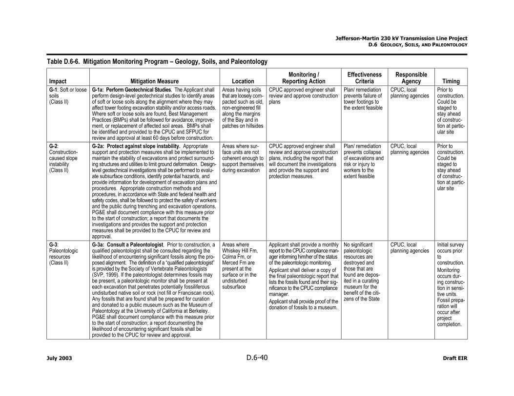
Jefferson-Martin 230 kV Transmission Line Project D.6 GEOLOGY, SOILS, AND PALEONTOLOGY
Table D.6-6. Mitigation Monitoring Program – Geology, Soils, and Paleontology
Impact Mitigation Measure Location Monitoring /
Reporting Action Effectiveness
Criteria Responsible
Agency TimingG-1: Soft or loose soils (Class II)
G-1a: Perform Geotechnical Studies. The Applicant shall perform design-level geotechnical studies to identify areas of soft or loose soils along the alignment where they may affect tower footing excavation stability and/or access roads. Where soft or loose soils are found, Best Management Practices (BMPs) shall be followed for avoidance, improve-ment, or replacement of affected soil areas. BMPs shall be identified and provided to the CPUC and SFPUC for review and approval at least 60 days before construction.
Areas having soils that are loosely com-pacted such as old, non-engineered fill along the margins of the Bay and in patches on hillsides
CPUC approved engineer shall review and approve construction plans
Plan/ remediation prevents failure of tower footings to the extent feasible
CPUC, local planning agencies
Prior to construction. Could be staged to stay ahead of construc-tion at partic-ular site
G-2: Construction-caused slope instability (Class II)
G-2a: Protect against slope instability. Appropriate support and protection measures shall be implemented to maintain the stability of excavations and protect surround-ing structures and utilities to limit ground deformation. Design-level geotechnical investigations shall be performed to evalu-ate subsurface conditions, identify potential hazards, and provide information for development of excavation plans and procedures. Appropriate construction methods and procedures, in accordance with State and federal health and safety codes, shall be followed to protect the safety of workers and the public during trenching and excavation operations. PG&E shall document compliance with this measure prior to the start of construction; a report that documents the investigations and provides the support and protection measures shall be provided to the CPUC for review and approval.
Areas where sur-face units are not coherent enough to support themselves during excavation
CPUC approved engineer shall review and approve construction plans, including the report that will document the investigations and provide the support and protection measures.
Plan/ remediation prevents collapse of excavations and risk or injury to workers to the extent feasible
CPUC, local planning agencies
Prior to construction. Could be staged to stay ahead of construc-tion at partic-ular site
G-3: Paleontologic resources (Class II)
G-3a: Consult a Paleontologist. Prior to construction, a qualified paleontologist shall be consulted regarding the likelihood of encountering significant fossils along the pro-posed alignment. The definition of a “qualified paleontologist” is provided by the Society of Vertebrate Paleontologists (SVP, 1999). If the paleontologist determines fossils may be present, a paleontologic monitor shall be present at each excavation that penetrates potentially fossiliferous undisturbed native soil or rock (not fill or Franciscan rock). Any fossils that are found shall be prepared for curation and donated to a public museum such as the Museum of Paleontology at the University of California at Berkeley. PG&E shall document compliance with this measure prior to the start of construction; a report documenting the likelihood of encountering significant fossils shall be provided to the CPUC for review and approval.
Areas where Whiskey Hill Fm, Colma Fm, or Merced Fm are present at the surface or in the undisturbed subsurface
Applicant shall provide a monthly report to the CPUC compliance man-ager informing him/her of the status of the paleontologic monitoring. Applicant shall deliver a copy of the final paleontologic report that lists the fossils found and their sig-nificance to the CPUC compliance manager. Applicant shall provide proof of the donation of fossils to a museum.
No significant paleontologic resources are destroyed and those that are found are depos-ited in a curating museum for the benefit of the citi-zens of the State
CPUC, local planning agencies
Initial survey occurs prior to construction. Monitoring occurs dur-ing construc-tion in sensi-tive units. Fossil prepa-ration will occur after project completion.
July 2003 D.6-40 Draft EIR
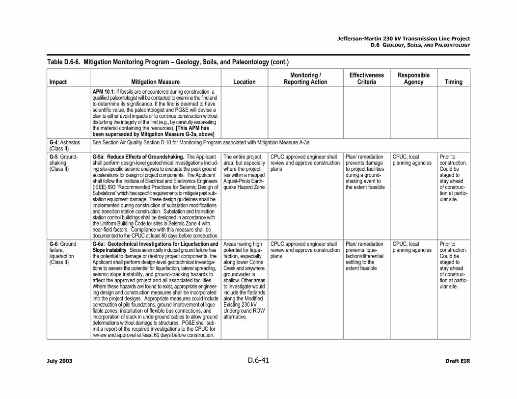
Jefferson-Martin 230 kV Transmission Line Project D.6 GEOLOGY, SOILS, AND PALEONTOLOGY
Table D.6-6. Mitigation Monitoring Program – Geology, Soils, and Paleontology (cont.)
Impact Mitigation Measure Location Monitoring /
Reporting Action Effectiveness
Criteria Responsible
Agency Timing APM 10.1: If fossils are encountered during construction, a qualified paleontologist will be contacted to examine the find and to determine its significance. If the find is deemed to have scientific value, the paleontologist and PG&E will devise a plan to either avoid impacts or to continue construction without disturbing the integrity of the find (e.g., by carefully excavating the material containing the resources). [This APM has been superseded by Mitigation Measure G-3a, above]
G-4: Asbestos (Class II)
See Section Air Quality Section D.10 for Monitoring Program associated with Mitigation Measure A-3a
G-5: Ground-shaking (Class II)
G-5a: Reduce Effects of Groundshaking. The Applicant shall perform design-level geotechnical investigations includ-ing site-specific seismic analyses to evaluate the peak ground accelerations for design of project components. The Applicant shall follow the Institute of Electrical and Electronics Engineers (IEEE) 693 “Recommended Practices for Seismic Design of Substations” which has specific requirements to mitigate past sub-station equipment damage. These design guidelines shall be implemented during construction of substation modifications and transition station construction. Substation and transition station control buildings shall be designed in accordance with the Uniform Building Code for sites in Seismic Zone 4 with near-field factors. Compliance with this measure shall be documented to the CPUC at least 60 days before construction.
The entire project area, but especially where the project lies within a mapped Alquist-Priolo Earth-quake Hazard Zone
CPUC approved engineer shall review and approve construction plans
Plan/ remediation prevents damage to project facilities during a ground-shaking event to the extent feasible
CPUC, local planning agencies
Prior to construction. Could be staged to stay ahead of construc-tion at partic-ular site.
G-6: Ground failure, liquefaction (Class II)
G-6a: Geotechnical Investigations for Liquefaction and Slope Instability. Since seismically induced ground failure has the potential to damage or destroy project components, the Applicant shall perform design-level geotechnical investiga-tions to assess the potential for liquefaction, lateral spreading, seismic slope instability, and ground-cracking hazards to affect the approved project and all associated facilities. Where these hazards are found to exist, appropriate engineer-ing design and construction measures shall be incorporated into the project designs. Appropriate measures could include construction of pile foundations, ground improvement of lique-fiable zones, installation of flexible bus connections, and incorporation of slack in underground cables to allow ground deformations without damage to structures. PG&E shall sub-mit a report of the required investigations to the CPUC for review and approval at least 60 days before construction.
Areas having high potential for lique-faction, especially along lower Colma Creek and anywhere groundwater is shallow. Other areas to investigate would include the flatlands along the Modified Existing 230 kV Underground ROW alternative.
CPUC approved engineer shall review and approve construction plans
Plan/ remediation prevents lique-faction/differential settling to the extent feasible
CPUC, local planning agencies
Prior to construction. Could be staged to stay ahead of construc-tion at partic-ular site.
July 2003 D.6-41 Draft EIR
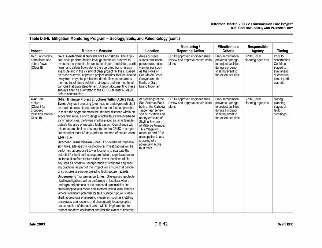
Jefferson-Martin 230 kV Transmission Line Project D.6 GEOLOGY, SOILS, AND PALEONTOLOGY
Table D.6-6. Mitigation Monitoring Program – Geology, Soils, and Paleontology (cont.)
Impact Mitigation Measure Location Monitoring /
Reporting Action Effectiveness
Criteria Responsible
Agency Timing G-7: Landslides, earth flows and debris flows (Class II)
G-7a: Geotechnical Surveys for Landslides. The Appli-cant shall perform design-level geotechnical surveys to evaluate the potential for unstable slopes, landslides, earth flows, and debris flows along the approved transmission line route and in the vicinity of other project facilities. Based on these surveys, approved project facilities shall be located away from very steep hillsides, debris-flow source areas, the mouths of steep sidehill drainages, and the mouths of canyons that drain steep terrain. A report documenting these surveys shall be submitted to the CPUC at least 60 days before construction
Areas of steep slopes and incom-petent rock, collu-vium or soil such as the sides of San Mateo Creek Canyon and the flanks of San Bruno Mountain
CPUC approved engineer shall review and approve construction plans
Plan/ remediation prevents damage to project facilities during a ground-shaking event to the extent feasible
CPUC, local planning agencies
Prior to construction. Could be staged to stay ahead of construc-tion at partic-ular site
G-8: Fault rupture (Class I for proposed transition station; Class II)
G-8a: Minimize Project Structures Within Active Fault Zone. Any fault crossing (overhead or underground) shall be made as close to perpendicular to the fault as possible to make the segment cross the shortest distance within an active fault zone. For crossings of active faults with overhead transmission lines, the towers shall be placed as far as feasible outside the area of mapped fault traces. Compliance with this measure shall be documented to the CPUC in a report submitted at least 60 days prior to the start of construction. APM 10.2: Overhead Transmission Lines. For overhead transmis-sion lines, site-specific geotechnical investigations will be performed at proposed tower locations to evaluate the potential for fault surface rupture. Where significant poten-tial for fault surface rupture exists, tower locations will be adjusted as possible. Incorporation of standard engineer-ing practices as part of the Project will ensure that people or structures are not exposed to fault rupture hazards. Underground Transmission Lines. Site-specific geotech-nical investigations will be performed at locations where underground portions of the proposed transmission line cross mapped fault zones and intersect individual fault traces. Where significant potential for fault surface rupture is iden-tified, appropriate engineering measures, such as installing breakaway connections and strategically locating splice boxes outside of the fault zone, will be implemented to protect sensitive equipment and limit the extent of potential
At crossings of the San Andreas Fault both at the Cañada Trace near Jeffer-son Substation and at any crossing of Skyline Blvd north of Millbrae Avenue. This mitigation measure and APM also applies to any crossing of a potentially active fault trace.
CPUC approved engineer shall review and approve construction plans
Plan/ remediation prevents damage to project facilities during a ground-shaking event to the extent feasible
CPUC, local planning agencies
During planning stages of fault crossings.
July 2003 D.6-42 Draft EIR
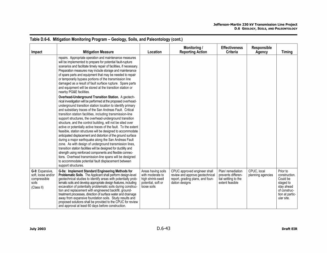
Jefferson-Martin 230 kV Transmission Line Project D.6 GEOLOGY, SOILS, AND PALEONTOLOGY
Table D.6-6. Mitigation Monitoring Program – Geology, Soils, and Paleontology (cont.)
Impact Mitigation Measure Location Monitoring /
Reporting Action Effectiveness
Criteria Responsible
Agency Timing repairs. Appropriate operation and maintenance measures will be implemented to prepare for potential fault-rupture scenarios and facilitate timely repair of facilities, if necessary. Preparation measures may include storage and maintenance of spare parts and equipment that may be needed to repair or temporarily bypass portions of the transmission line damaged as a result of fault surface rupture. Spare parts and equipment will be stored at the transition station or nearby PG&E facilities. Overhead-Underground Transition Station. A geotech-nical investigation will be performed at the proposed overhead-underground transition station location to identify primary and subsidiary traces of the San Andreas Fault. Critical transition station facilities, including transmission-line support structures, the overhead-underground transition structure, and the control building, will not be sited over active or potentially active traces of the fault. To the extent feasible, station structures will be designed to accommodate anticipated displacement and distortion of the ground surface during a major earthquake along the San Andreas Fault zone. As with design of underground transmission lines, transition station facilities will be designed for ductility and strength using reinforced components and flexible connec-tions. Overhead transmission-line spans will be designed to accommodate potential fault displacement between support structures.
G-9: Expansive, soft, loose and/or compressible soils (Class II)
G-9a: Implement Standard Engineering Methods for Problematic Soils. The Applicant shall perform design-level geotechnical studies to identify areas with potentially prob-lematic soils and develop appropriate design features, including excavation of potentially problematic soils during construc-tion and replacement with engineered backfill, ground-treatment processes, direction of surface water and drainage away from expansive foundation soils. Study results and proposed solutions shall be provided to the CPUC for review and approval at least 60 days before construction.
Areas having soils with moderate to high shrink-swell potential, soft or loose soils
CPUC approved engineer shall review and approve geotechnical report, grading plans, and foun-dation designs
Plan/ remediation prevents differen-tial settling to the extent feasible
CPUC, local planning agencies
Prior to construction. Could be staged to stay ahead of construc-tion at partic-ular site.
July 2003 D.6-43 Draft EIR
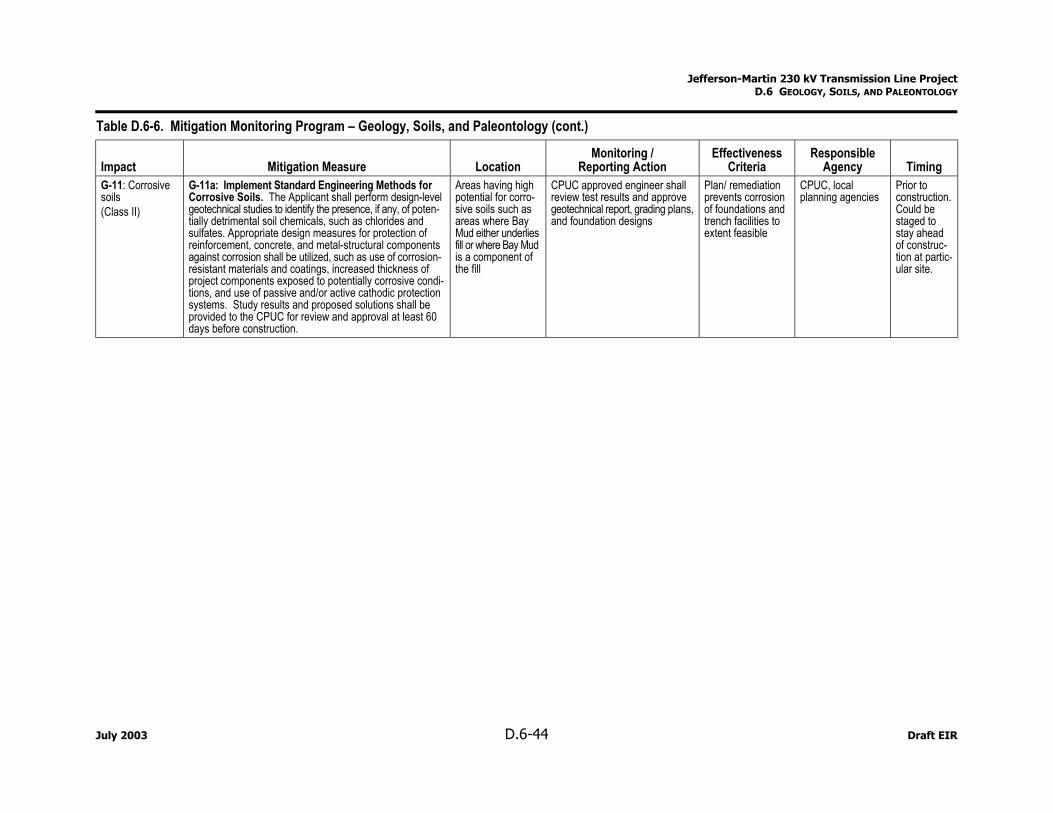
Jefferson-Martin 230 kV Transmission Line Project D.6 GEOLOGY, SOILS, AND PALEONTOLOGY
Table D.6-6. Mitigation Monitoring Program – Geology, Soils, and Paleontology (cont.)
Impact Mitigation Measure Location Monitoring /
Reporting Action Effectiveness
Criteria Responsible
Agency Timing G-11: Corrosive soils (Class II)
G-11a: Implement Standard Engineering Methods for Corrosive Soils. The Applicant shall perform design-level geotechnical studies to identify the presence, if any, of poten-tially detrimental soil chemicals, such as chlorides and sulfates. Appropriate design measures for protection of reinforcement, concrete, and metal-structural components against corrosion shall be utilized, such as use of corrosion-resistant materials and coatings, increased thickness of project components exposed to potentially corrosive condi-tions, and use of passive and/or active cathodic protection systems. Study results and proposed solutions shall be provided to the CPUC for review and approval at least 60 days before construction.
Areas having high potential for corro-sive soils such as areas where Bay Mud either underlies fill or where Bay Mud is a component of the fill
CPUC approved engineer shall review test results and approve geotechnical report, grading plans, and foundation designs
Plan/ remediation prevents corrosion of foundations and trench facilities to extent feasible
CPUC, local planning agencies
Prior to construction. Could be staged to stay ahead of construc-tion at partic-ular site.
July 2003 D.6-44 Draft EIR