Embed Size (px)
Citation preview
Journal of Advanced Ceramics 2018, 7(1): 17–29 ISSN 2226-4108https://doi.org/10.1007/s40145-017-0252-2 CN 10-1154/TQ
Research Article
www.springer.com/journal/40145
Epitaxial growth and cracking of highly tough
7YSZ splats by thermal spray technology
Lin CHEN, Guan-Jun YANG*
State Key Laboratory for Mechanical Behavior of Materials, School of Materials Science and Engineering, Xi’an Jiaotong University, Xi’an, Shaanxi 710049, China
Received: June 16, 2017; Revised: August 22, 2017; Accepted: October 27, 2017
© The Author(s) 2017. This article is published with open access at Springerlink.com
Abstract: Thermally sprayed coatings are essentially layered materials and contain large numbers of lamellar pores. It is thus quite necessary to clarify the formation mechanism of lamellar pores which significantly influence coating performances. In the present study, to elaborate the formation mechanism of lamellar pores, the yttria-stabilized zirconia (ZrO2–7 wt% Y2O3, 7YSZ) splats, which have high fracture toughness and tetragonal phase stability, were employed. Interestingly, anomalous epitaxial growth occurred for all deposition temperatures in spite of the extremely high cooling rate, which clearly indicated chemical bonding and complete contact at splat/substrate interface before splat cooling. However, transverse spallation substantially occurred for all deposition temperatures in spite of the high fracture toughness of 7YSZ, which revealed that the lamellar pores were from transverse cracking/spallation due to the large stress during splat cooling. Additionally, fracture mechanics analysis was carried out, and it was found that the stress arose from the constraint effect of the shrinkage of the splat by locally heated substrate with the value about 1.97 GPa. This clearly demonstrated that the stress was indeed large enough to drive transverse cracking/spallation forming lamellar pores during splat cooling. All of these contribute to understanding the essential features of lamellar bonding and further tailoring the coating structures and performance.
Keywords: epitaxial growth; crack patterns; transverse cracking/spallation; stress; locally heated substrate
1 Introduction
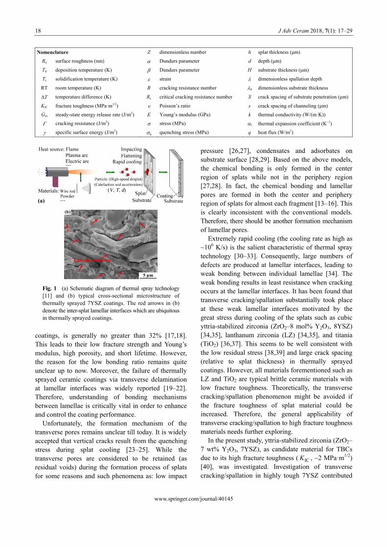
Thermally sprayed technology is widely used for deposition of thermal barrier coatings (TBCs) [1–4], abradable seal coatings [5,6], wear-resistant coatings [7,8], and functional layers in solid oxide fuel cells (SOFCs) [9,10], etc. The thermally sprayed coating is constructed by piling up the individual splats layer by layer (Fig. 1(a)) [11], so there are thus large numbers of inter-splat lamellar interfaces (see red arrows in Fig. * Corresponding author.
1(b)) in thermally sprayed coatings which significantly influence their functional properties. In addition, ubiquitous vertical cracks and transverse pores are widely observed in thermally sprayed coatings which are also of great importance to the coating performances [12–16]. Apparently, both the chemical bonding and mechanical anchoring (via friction) exist in thermally sprayed coatings. The former mainly sustains the loads, while the latter corresponds to lamellar pores. It is found that the bonding ratio, which is defined as the ratio of total bonded lamellar interface areas to the total apparent interface areas between splats in the E-mail: [email protected]
18 J Adv Ceram 2018, 7(1): 17–29
Nomenclature Z dimensionless number h splat thickness (μm)
Ra
surface roughness (nm) Dundurs parameter d depth (μm)
Td
deposition temperature (K) Dundurs parameter H substrate thickness (μm)
Ts
solidification temperature (K) strain dimensionless spallation depth
RT room temperature (K) R cracking resistance number 0 dimensionless substrate thickness
T temperature difference (K) Rc
critical cracking resistance number S crack spacing of substrate penetration (μm)
KIC
fracture toughness (MPa·m1/2) Poisson’s ratio s crack spacing of channeling (μm)
Gss
steady-state energy release rate (J/m2) E Young’s modulus (GPa) k thermal conductivity (W/(m·K))
cracking resistance (J/m2)
stress (MPa) t thermal expansion coefficient (K1)
specific surface energy (J/m2) q
quenching stress (MPa) q heat flux (W/m2)
Fig. 1 (a) Schematic diagram of thermal spray technology [11] and (b) typical cross-sectional microstructure of thermally sprayed 7YSZ coatings. The red arrows in (b) denote the inter-splat lamellar interfaces which are ubiquitous in thermally sprayed coatings.
coatings, is generally no greater than 32% [17,18]. This leads to their low fracture strength and Young’s modulus, high porosity, and short lifetime. However, the reason for the low bonding ratio remains quite unclear up to now. Moreover, the failure of thermally sprayed ceramic coatings via transverse delamination at lamellar interfaces was widely reported [19–22]. Therefore, understanding of bonding mechanisms between lamellae is critically vital in order to enhance and control the coating performance.
Unfortunately, the formation mechanism of the transverse pores remains unclear till today. It is widely accepted that vertical cracks result from the quenching stress during splat cooling [23–25]. While the transverse pores are considered to be retained (as residual voids) during the formation process of splats for some reasons and such phenomena as: low impact
pressure [26,27], condensates and adsorbates on substrate surface [28,29]. Based on the above models, the chemical bonding is only formed in the center region of splats while not in the periphery region [27,28]. In fact, the chemical bonding and lamellar pores are formed in both the center and periphery region of splats for almost each fragment [13–16]. This is clearly inconsistent with the conventional models. Therefore, there should be another formation mechanism of lamellar pores.
Extremely rapid cooling (the cooling rate as high as ~106 K/s) is the salient characteristic of thermal spray technology [30–33]. Consequently, large numbers of defects are produced at lamellar interfaces, leading to weak bonding between individual lamellae [34]. The weak bonding results in least resistance when cracking occurs at the lamellar interfaces. It has been found that transverse cracking/spallation substantially took place at these weak lamellar interfaces motivated by the great stress during cooling of the splats such as cubic yttria-stabilized zirconia (ZrO2–8 mol% Y2O3, 8YSZ) [34,35], lanthanum zirconia (LZ) [34,35], and titania (TiO2) [36,37]. This seems to be well consistent with the low residual stress [38,39] and large crack spacing (relative to splat thickness) in thermally sprayed coatings. However, all materials forementioned such as LZ and TiO2 are typical brittle ceramic materials with low fracture toughness. Theoretically, the transverse cracking/spallation phenomenon might be avoided if the fracture toughness of splat material could be increased. Therefore, the general applicability of transverse cracking/spallation to high fracture toughness materials needs further exploring.
In the present study, yttria-stabilized zirconia (ZrO2– 7 wt% Y2O3, 7YSZ), as candidate material for TBCs due to its high fracture toughness ( , ~2 MPa·m1/2) [40], was investigated. Investigation of transverse cracking/spallation in highly tough 7YSZ contributed
ICK
www.springer.com/journal/40145
J Adv Ceram 2018, 7(1): 17–29 19
2. 2 Splat deposition to deeply understanding the formation mechanism of lamellar pores in thermally sprayed coatings and further shedding light on the coating structure tailoring.
2 Experiment
2. 1 Powder and substrate material
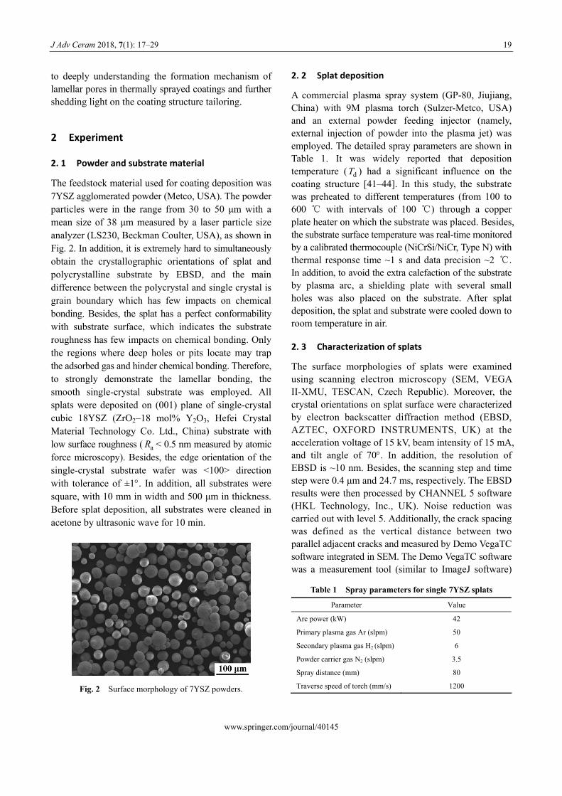
The feedstock material used for coating deposition was 7YSZ agglomerated powder (Metco, USA). The powder particles were in the range from 30 to 50 μm with a mean size of 38 μm measured by a laser particle size analyzer (LS230, Beckman Coulter, USA), as shown in Fig. 2. In addition, it is extremely hard to simultaneously obtain the crystallographic orientations of splat and polycrystalline substrate by EBSD, and the main difference between the polycrystal and single crystal is grain boundary which has few impacts on chemical bonding. Besides, the splat has a perfect conformability with substrate surface, which indicates the substrate roughness has few impacts on chemical bonding. Only the regions where deep holes or pits locate may trap the adsorbed gas and hinder chemical bonding. Therefore, to strongly demonstrate the lamellar bonding, the smooth single-crystal substrate was employed. All splats were deposited on (001) plane of single-crystal cubic 18YSZ (ZrO2–18 mol% Y2O3, Hefei Crystal Material Technology Co. Ltd., China) substrate with low surface roughness ( aR < 0.5 nm measured by atomic force microscopy). Besides, the edge orientation of the single-crystal substrate wafer was <100> direction with tolerance of ±1. In addition, all substrates were square, with 10 mm in width and 500 μm in thickness. Before splat deposition, all substrates were cleaned in acetone by ultrasonic wave for 10 min.
Fig. 2 Surface morphology of 7YSZ powders.
A commercial plasma spray system (GP-80, Jiujiang, China) with 9M plasma torch (Sulzer-Metco, USA) and an external powder feeding injector (namely, external injection of powder into the plasma jet) was employed. The detailed spray parameters are shown in Table 1. It was widely reported that deposition temperature ( ) had a significant influence on the coating structure [41–44]. In this study, the substrate was preheated to different temperatures (from 100 to 600 ℃ with intervals of 100 ℃) through a copper plate heater on which the substrate was placed. Besides, the substrate surface temperature was real-time monitored by a calibrated thermocouple (NiCrSi/NiCr, Type N) with thermal response time ~1 s and data precision ~2 ℃. In addition, to avoid the extra calefaction of the substrate by plasma arc, a shielding plate with several small holes was also placed on the substrate. After splat deposition, the splat and substrate were cooled down to room temperature in air.
dT
2. 3 Characterization of splats
The surface morphologies of splats were examined using scanning electron microscopy (SEM, VEGA II-XMU, TESCAN, Czech Republic). Moreover, the crystal orientations on splat surface were characterized by electron backscatter diffraction method (EBSD, AZTEC, OXFORD INSTRUMENTS, UK) at the acceleration voltage of 15 kV, beam intensity of 15 mA, and tilt angle of 70. In addition, the resolution of EBSD is ~10 nm. Besides, the scanning step and time step were 0.4 μm and 24.7 ms, respectively. The EBSD results were then processed by CHANNEL 5 software (HKL Technology, Inc., UK). Noise reduction was carried out with level 5. Additionally, the crack spacing was defined as the vertical distance between two parallel adjacent cracks and measured by Demo VegaTC software integrated in SEM. The Demo VegaTC software was a measurement tool (similar to ImageJ software)
Table 1 Spray parameters for single 7YSZ splats
Parameter Value
Arc power (kW) 42
Primary plasma gas Ar (slpm) 50
Secondary plasma gas H2 (slpm) 6
Powder carrier gas N2 (slpm) 3.5
Spray distance (mm) 80
Traverse speed of torch (mm/s) 1200
www.springer.com/journal/40145
20 J Adv Ceram 2018, 7(1): 17–29
with the measurement accuracy of about 0.1 μm. When measuring the crack spacing, all SEM images were taken at magnification larger than 1000×.
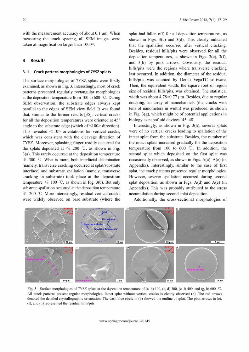
splat had fallen off) for all deposition temperatures, as shown in Figs. 3(c) and 3(d). This clearly indicated that the spallation occurred after vertical cracking. Besides, residual hills/pits were observed for all the deposition temperatures, as shown in Figs. 3(e), 3(f), and 3(h) by pink arrows. Obviously, the residual hills/pits were the regions where transverse cracking last occurred. In addition, the diameter of the residual hills/pits was counted by Demo VegaTC software. Then, the equivalent width, the square root of region size of residual hills/pits, was obtained. The statistical width was about 4.78±0.77 μm. Besides, due to regular cracking, an array of nanochannels (the cracks with tens of nanometers in width) was produced, as shown in Fig. 3(g), which might be of potential applications in biology as nanofluid devices [45–48].
3 Results
3. 1 Crack pattern morphologies of 7YSZ splats
The surface morphologies of 7YSZ splats were firstly examined, as shown in Fig. 3. Interestingly, most of crack patterns presented regularly rectangular morphologies at the deposition temperature from 100 to 600 ℃. During SEM observation, the substrate edges always kept parallel to the edges of SEM view field. It was found that, similar to the former results [35], vertical cracks for all the deposition temperatures were oriented at 45° angle to the substrate edge (which of <100> direction). This revealed <110> orientations for vertical cracks, which was consistent with the cleavage direction of 7YSZ. Moreover, splashing finger readily occurred for the splats deposited at ≤ 200 ℃, as shown in Fig. 3(a). This rarely occurred at the deposition temperature ≥ 300 ℃. What is more, both interfacial delamination (namely, transverse cracking occurred at splat/substrate interface) and substrate spallation (namely, transverse cracking in substrate) took place at the deposition temperature ≤ 100 ℃, as shown in Fig. 3(b). But only substrate spallation occurred at the deposition temperature ≥ 200 ℃. More interestingly, residual vertical cracks were widely observed on bare substrate (where the
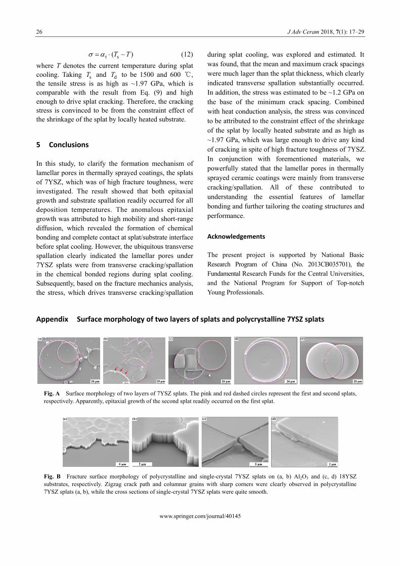
Interestingly, as shown in Fig. 3(h), several splats were of no vertical cracks leading to spallation of the intact splat from the substrate. Besides, the number of the intact splats increased gradually for the deposition temperature from 100 to 600 ℃ . In addition, the second splat which deposited on the first splat was occasionally observed, as shown in Figs. A(a)–A(e) (in Appendix). Interestingly, similar to the case of first splat, the crack patterns presented regular morphologies. However, severer spallation occurred during second splat deposition, as shown in Figs. A(d) and A(e) (in Appendix). This was probably attributed to the stress accumulation during second splat deposition.
Additionally, the cross-sectional morphologies of
Fig. 3 Surface morphologies of 7YSZ splats at the deposition temperature of (a, b) 100, (c, d) 300, (e, f) 400, and (g, h) 600 ℃. All crack patterns present regular morphologies. Intact splat without vertical cracks is clearly observed (h). The red arrows denoted the detailed crystallographic orientation. The dash blue circle in (b) showed the outline of splat. The pink arrows in (e), (f), and (h) represented the residual hills/pits.
www.springer.com/journal/40145
J Adv Ceram 2018, 7(1): 17–29 21
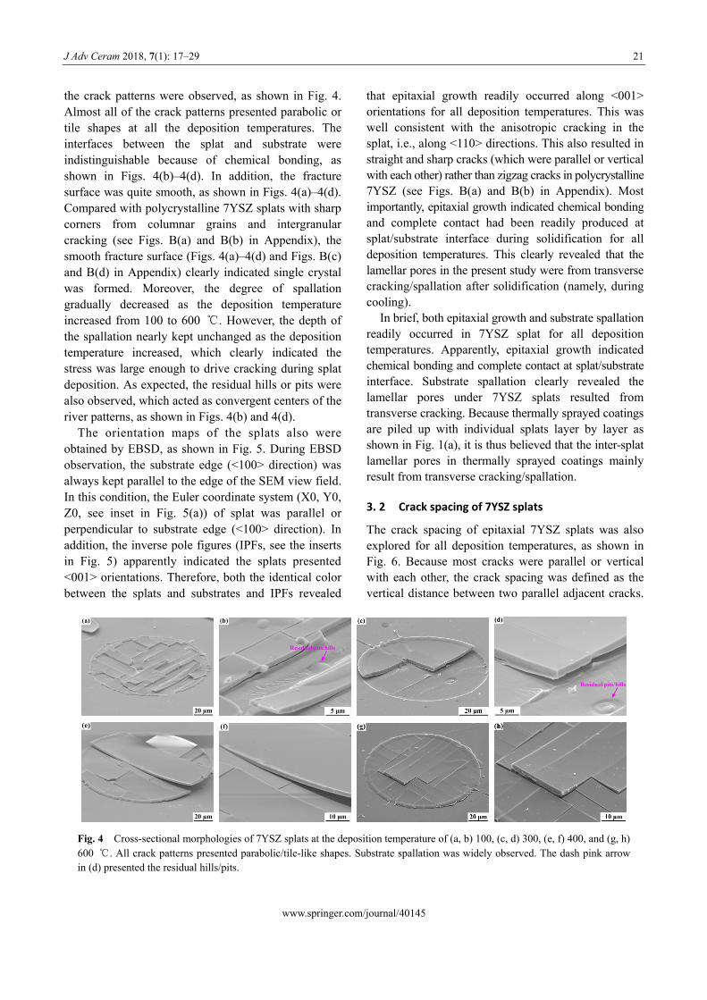
the crack patterns were observed, as shown in Fig. 4. Almost all of the crack patterns presented parabolic or tile shapes at all the deposition temperatures. The interfaces between the splat and substrate were indistinguishable because of chemical bonding, as shown in Figs. 4(b)–4(d). In addition, the fracture surface was quite smooth, as shown in Figs. 4(a)–4(d). Compared with polycrystalline 7YSZ splats with sharp corners from columnar grains and intergranular cracking (see Figs. B(a) and B(b) in Appendix), the smooth fracture surface (Figs. 4(a)–4(d) and Figs. B(c) and B(d) in Appendix) clearly indicated single crystal was formed. Moreover, the degree of spallation gradually decreased as the deposition temperature increased from 100 to 600 ℃. However, the depth of the spallation nearly kept unchanged as the deposition temperature increased, which clearly indicated the stress was large enough to drive cracking during splat deposition. As expected, the residual hills or pits were also observed, which acted as convergent centers of the river patterns, as shown in Figs. 4(b) and 4(d).
The orientation maps of the splats also were obtained by EBSD, as shown in Fig. 5. During EBSD observation, the substrate edge (<100> direction) was always kept parallel to the edge of the SEM view field. In this condition, the Euler coordinate system (X0, Y0, Z0, see inset in Fig. 5(a)) of splat was parallel or perpendicular to substrate edge (<100> direction). In addition, the inverse pole figures (IPFs, see the inserts in Fig. 5) apparently indicated the splats presented <001> orientations. Therefore, both the identical color between the splats and substrates and IPFs revealed
that epitaxial growth readily occurred along <001> orientations for all deposition temperatures. This was well consistent with the anisotropic cracking in the splat, i.e., along <110> directions. This also resulted in straight and sharp cracks (which were parallel or vertical with each other) rather than zigzag cracks in polycrystalline 7YSZ (see Figs. B(a) and B(b) in Appendix). Most importantly, epitaxial growth indicated chemical bonding and complete contact had been readily produced at splat/substrate interface during solidification for all deposition temperatures. This clearly revealed that the lamellar pores in the present study were from transverse cracking/spallation after solidification (namely, during cooling).
In brief, both epitaxial growth and substrate spallation readily occurred in 7YSZ splat for all deposition temperatures. Apparently, epitaxial growth indicated chemical bonding and complete contact at splat/substrate interface. Substrate spallation clearly revealed the lamellar pores under 7YSZ splats resulted from transverse cracking. Because thermally sprayed coatings are piled up with individual splats layer by layer as shown in Fig. 1(a), it is thus believed that the inter-splat lamellar pores in thermally sprayed coatings mainly result from transverse cracking/spallation.
3. 2 Crack spacing of 7YSZ splats
The crack spacing of epitaxial 7YSZ splats was also explored for all deposition temperatures, as shown in Fig. 6. Because most cracks were parallel or vertical with each other, the crack spacing was defined as the vertical distance between two parallel adjacent cracks.
Fig. 4 Cross-sectional morphologies of 7YSZ splats at the deposition temperature of (a, b) 100, (c, d) 300, (e, f) 400, and (g, h) 600 ℃. All crack patterns presented parabolic/tile-like shapes. Substrate spallation was widely observed. The dash pink arrow in (d) presented the residual hills/pits.
www.springer.com/journal/40145
22 J Adv Ceram 2018, 7(1): 17–29
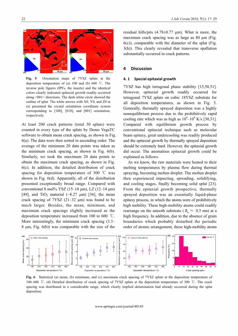
Fig. 5 Orientation maps of 7YSZ splats at the deposition temperature of (a) 100 and (b) 600 ℃. The inverse pole figures (IPFs, the inserts) and the identical colors clearly indicated epitaxial growth readily occurred along <001> directions. The dash white circle showed the outline of splat. The white arrows with X0, Y0, and Z0 in (a) presented the crystal orientation coordinate system corresponding to [100], [010], and [001] orientation, respectively.
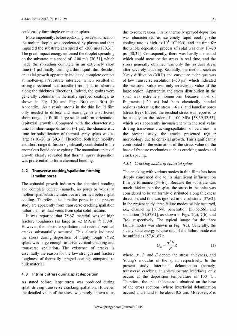
At least 200 crack patterns (total 30 splats) were counted in every type of the splats by Demo VegaTC software to obtain mean crack spacing, as shown in Fig. 6(a). The data were then sorted in ascending order. The average of the minimum 20 data points was taken as the minimum crack spacing, as shown in Fig. 6(b). Similarly, we took the maximum 20 data points to obtain the maximum crack spacing, as shown in Fig. 6(c). In addition, the detailed distribution of crack spacing for deposition temperature of 300 ℃ was shown in Fig. 6(d). Apparently, all of the distribution presented exceptionally broad range. Compared with conventional 8 mol% YSZ (15–18 μm), LZ (12–14 μm) [49], and TiO2 material (~8.27 μm) [36], the mean crack spacing of 7YSZ (21–32 μm) was found to be much larger. Besides, the mean, minimum, and maximum crack spacings slightly increased as the deposition temperature increased from 100 to 600 ℃. More interestingly, the minimum crack spacing (3.3– 8 μm, Fig. 6(b)) was comparable with the size of the
residual hills/pits (4.78±0.77 μm). What is more, the maximum crack spacing was as large as 80 μm (Fig. 6(c)), comparable with the diameter of the splat (Fig. 3(h)). This clearly revealed that transverse spallation substantially occurred in crack patterns.
4 Discussion
4. 1 Special epitaxial growth
7YSZ has high tetragonal phase stability [15,50,51]. However, epitaxial growth readily occurred for tetragonal 7YSZ splats on cubic 18YSZ substrate for all deposition temperatures, as shown in Fig. 5. Generally, thermally sprayed deposition was a highly nonequilibrium process due to the prohibitively rapid cooling rate which was as high as 104–108 K/s [30,31]. Compared with equilibrium growth process by conventional epitaxial technique such as molecular beam epitaxy, great undercooling was readily produced and the epitaxial growth by thermally sprayed deposition should be extremely hard. However, the epitaxial growth did occur. The anomalous epitaxial growth could be explained as follows.
As we know, the raw materials were heated to their melting temperatures by plasma flow during thermal spraying, becoming molten droplet. The molten droplet then experienced impacting, spreading, solidifying, and cooling stages, finally becoming solid splat [23]. From the epitaxial growth prospective, thermally sprayed deposition was an essentially liquid-phase epitaxy process, in which the atoms were of prohibitively high mobility. These high-mobility atoms could readily rearrange on the smooth substrate ( ≈ 0.5 nm) at a high frequency. In addition, due to the absence of grain boundaries which probably disturbed the periodic order of atomic arrangement, these high-mobility atoms
aR
Fig. 6 Statistical (a) mean, (b) minimum, and (c) maximum crack spacing of 7YSZ splats at the deposition temperature of 100–600 ℃. (d) Detailed distribution of crack spacing of 7YSZ splats at the deposition temperature of 300 ℃. The crack spacing was distributed in a considerable range, which clearly implied delamination had already occurred during the splat deposition.
www.springer.com/journal/40145
J Adv Ceram 2018, 7(1): 17–29 23
could easily form single-orientation splats.
More importantly, before epitaxial growth/solidification, the molten droplet was accelerated by plasma and then impacted the substrate at a speed of ~200 m/s [30,31]. The great impact energy enforced the droplet spreading on the substrate at a speed of ~100 m/s [30,31], which made the spreading complete in an extremely short time (~1 μs) finally forming a thin liquid film. Besides, epitaxial growth apparently indicated complete contact at molten-splat/substrate interface, which resulted in strong directional heat transfer (from splat to substrate along the thickness direction). Indeed, the grains were generally columnar in thermally sprayed coatings, as shown in Fig. 1(b) and Figs. B(a) and B(b) (in Appendix). As a result, atoms in the thin liquid film only needed to diffuse and rearrange in a sufficient short range to fulfill large-scale uniform orientation (epitaxial growth). Compared with the characteristic time for short-range diffusion (~1 μs), the characteristic time for solidification of thermal spray splats was as large as 10–20 μs [30,31]. Therefore, both high mobility and short-range diffusion significantly contributed to the anomalous liquid-phase epitaxy. The anomalous epitaxial growth clearly revealed that thermal spray deposition was preferential to form chemical bonding.
4. 2 Transverse cracking/spallation forming lamellar pores
The epitaxial growth indicates the chemical bonding and complete contact (namely, no pores or voids) at molten-splat/substrate interface are formed before splat cooling. Therefore, the lamellar pores in the present study are apparently from transverse cracking/spallation rather than residual voids from splat solidification.
It was reported that 7YSZ material was of high fracture toughness (as large as ~2 MPa·m1/2) [3,40]. However, the substrate spallation and residual vertical cracks substantially occurred. This clearly indicated the stress during deposition of highly tough 7YSZ splats was large enough to drive vertical cracking and transverse spallation. The existence of cracks is essentially the reason for the low strength and fracture toughness of thermally sprayed coatings compared to bulk material.
4. 3 Intrinsic stress during splat deposition
As stated before, large stress was produced during splat, driving transverse cracking/spallation. However, the detailed value of the stress was rarely known to us
due to some reasons. Firstly, thermally sprayed deposition was characterized as extremely rapid cooling (the cooling rate as high as 104–108 K/s), and the time for the whole deposition process of splat was only 10–20 μs [30,31]. Consequently, there was hardly a method which could measure the stress in real time, and the stress generally obtained was only the residual stress after severely cracking. Secondly, the method such as X-ray diffraction (XRD) and curvature technique was of low transverse resolution (~50 μs), which indicated the measured value was only an average value of the large region. Apparently, the stress distribution in the splat was extremely nonuniform because most of fragments (~20 μs) had both chemically bonded regions (tolerating the stress, ~6 μs) and lamellar pores (stress free). Indeed, the residual stress was reported to be usually on the order of ~100 MPa [38,39,52,53], which was apparently inconsistent with the real value driving transverse cracking/spallation of ceramics. In the present study, the cracks presented regular morphology due to epitaxial growth. This significantly contributed to the estimation of the stress value on the base of fracture mechanics such as cracking modes and crack spacing.
4.3.1 Cracking modes of epitaxial splats
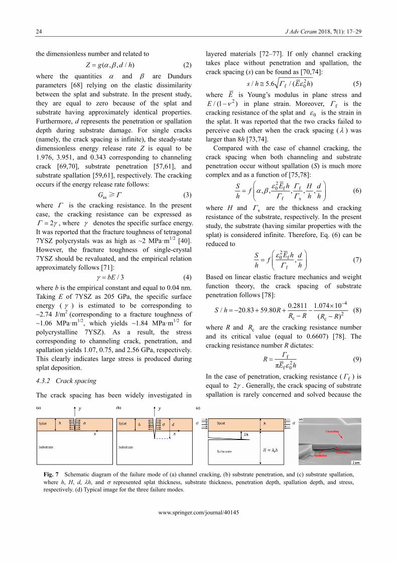
The cracking with various modes in thin films has been deeply concerned due to its significant influence on film performance [54–61]. Because the substrate was much thicker than the splat, the stress in the splat was considered to be uniformly distributed along thickness direction, and this was ignored in the substrate [37,62]. In the present study, three failure modes mainly occurred, i.e., channeling [63,64], penetration [56,65,66], and spallation [54,57,61], as shown in Figs. 7(a), 7(b), and 7(c), respectively. The typical image for the three failure modes was shown in Fig. 7(d). Generally, the steady-state energy release rate of the failure mode can be unified as [57,61,67]:
2
ssh
GE
Z (1)
where , h, and E denote the stress, thickness, and Young’s modulus of the splat, respectively. In the present study, interfacial delamination (namely, transverse cracking at splat/substrate interface) only occurs at the deposition temperature of 100 ℃ . Therefore, the splat thickness is obtained on the base of the cross sections (where interfacial delamination occurs) and found to be about 0.5 μm. Moreover, Z is
www.springer.com/journal/40145
24 J Adv Ceram 2018, 7(1): 17–29
the dimensionless number and related to
www.springer.com/journal/40145
( , , / )Z g d h (2)
layered materials [72–77]. If only channel cracking takes place without penetration and spallation, the crack spacing (s) can be found as [70,74]:
where the quantities and are Dundurs parameters [68] relying on the elastic dissimilarity between the splat and substrate. In the present study, they are equal to zero because of the splat and substrate having approximately identical properties. Furthermore, d represents the penetration or spallation depth during substrate damage. For single cracks (namely, the crack spacing is infinite), the steady-state dimensionless energy release rate Z is equal to be 1.976, 3.951, and 0.343 corresponding to channeling crack [69,70], substrate penetration [57,61], and substrate spallation [59,61], respectively. The cracking occurs if the energy release rate follows:
2
f 0/ 5.6 / ( )s h E h (5)
where E is Young’s modulus in plane stress and 2/ (1 )E in plane strain. Moreover, f is the
cracking resistance of the splat and 0 is the strain in the splat. It was reported that the two cracks failed to perceive each other when the crack spacing ( ) was larger than 8h [73,74].
Compared with the case of channel cracking, the crack spacing when both channeling and substrate penetration occur without spallation (S) is much more complex and as a function of [75,78]:
(3) ssG ≥
20 f f
f s
, , , , ,E hS
fh h
H d
h (6)
where is the cracking resistance. In the present case, the cracking resistance can be expressed as
, where
2 denotes the specific surface energy. It was reported that the fracture toughness of tetragonal 7YSZ polycrystals was as high as ~2 MPa·m1/2 [40]. However, the fracture toughness of single-crystal 7YSZ should be revaluated, and the empirical relation approximately follows [71]:
where H and s are the thickness and cracking resistance of the substrate, respectively. In the present study, the substrate (having similar properties with the splat) is considered infinite. Therefore, Eq. (6) can be reduced to
/ 3bE (4)
20 f
f
,E hS
fh h
d (7)
Based on linear elastic fracture mechanics and weight function theory, the crack spacing of substrate penetration follows [78]:
where b is the empirical constant and equal to 0.04 nm. Taking E of 7YSZ as 205 GPa, the specific surface energy ( ) is estimated to be corresponding to ~2.74 J/m2 (corresponding to a fracture toughness of ~1.06 MPa·m1/2, which yields ~1.84 MPa·m1/2 for polycrystalline 7YSZ). As a result, the stress corresponding to channeling crack, penetration, and spallation yields 1.07, 0.75, and 2.56 GPa, respectively. This clearly indicates large stress is produced during splat deposition.
4
2c c
0.2811 1.074 10/ 20.83 59.80
( )S h R
R R R R
(8)
where R and are the cracking resistance number and its critical value (equal to 0.6607) [78]. The cracking resistance number R dictates:
cR
f2
f 0π
ΓR
E h
(9)
In the case of penetration, cracking resistance ( ) is equal to
fΓ2 . Generally, the crack spacing of substrate
spallation is rarely concerned and solved because the
4.3.2 Crack spacing
The crack spacing has been widely investigated in
Fig. 7 Schematic diagram of the failure mode of (a) channel cracking, (b) substrate penetration, and (c) substrate spallation, where h, H, d, h, and represented splat thickness, substrate thickness, penetration depth, spallation depth, and stress, respectively. (d) Typical image for the three failure modes.
J Adv Ceram 2018, 7(1): 17–29 25
spallation won’t stop until meeting another defects [57], namely, the crack spacing is usually considered infinite.
In the present study, the crack patterns firstly experience penetration, then channel cracking, and last spallation. Therefore, the crack spacing is a result of the combined action of penetration and spallation. In this case, the normal crack spacing (S) has no use to sustain the mechanical equilibrium configuration. Inversely, the stress transfer from the splat to the substrate only takes place over the portion of the segment where no spallation propagates. This defines an effective crack spacing [77,79], which can be equivalent with this of pure penetration. The differences between the case with and without spallation only lie in the stored energy by delaminated composite beams in the former case.
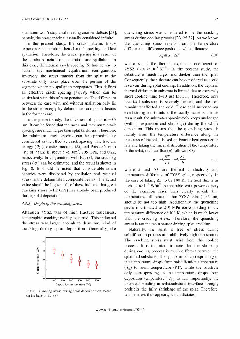
In the present study, the thickness of splats is ~0.5 μm. It can be found that the mean and maximum crack spacings are much larger than splat thickness. Therefore, the minimum crack spacing can be approximately considered as the effective crack spacing. The fracture energy ( 2 ), elastic modulus (E), and Poisson’s ratio ( ) of 7YSZ is about 5.48 J/m2, 205 GPa, and 0.22, respectively. In conjunction with Eq. (8), the cracking stress ( ) can be estimated, and the result is shown in Fig. 8. It should be noted that considerable strain energies were dissipated by spallation and residual stress in the delaminated composite beams. The actual value should be higher. All of these indicate that great cracking stress (~1.2 GPa) has already been produced during splat deposition.
4.3.3 Origin of the cracking stress
Although 7YSZ was of high fracture toughness, catastrophic cracking readily occurred. This indicated the stress was larger enough to drive any kind of cracking during splat deposition. Generally, the
Fig. 8 Cracking stress during splat deposition estimated on the base of Eq. (8).
quenching stress was considered to be the cracking stress during cooling process [23–25,39]. As we know, the quenching stress results from the temperature difference at difference positions, which dictates:
q t T (10)
where t is the thermal expansion coefficient of 7YSZ (~10.7×10⁻⁶
K1). In the present study, the substrate is much larger and thicker than the splat. Consequently, the substrate can be considered as a vast reservoir during splat cooling. In addition, the depth of thermal diffusion in substrate is limited due to extremely short cooling time (~10 μs) [30,31]. Therefore, only localized substrate is severely heated, and the rest remains unaffected and cold. These cold surroundings exert strong constraints to the locally heated substrate. As a result, the substrate approximately keeps unchanged (without expansion and shrinkage) during the whole deposition. This means that the quenching stress is mainly from the temperature difference along the thickness of the splat. Based on Fourier heat conduction law and taking the linear distribution of the temperature in the splat, the heat flux (q) follows [80]:
T Tq k k
x h
(11)
where k and ΔT are thermal conductivity and temperature difference of 7YSZ splat, respectively. In the case of taking ΔT to be 100 K, the heat flux is as high as 6×10⁸ W/m2, comparable with power density of the common laser. This clearly reveals that temperature difference in thin 7YSZ splat (~0.5 μm) should be not too high. Additionally, the quenching stress is estimated to 219 MPa corresponding to the temperature difference of 100 K, which is much lower than the cracking stress. Therefore, the quenching stress is not the main source driving splat cracking.
Naturally, the splat is free of stress during solidification process at prohibitively high temperature. The cracking stress must arise from the cooling process. It is important to note that the shrinkage during cooling process is much different between the splat and substrate. The splat shrinks corresponding to the temperature drops from solidification temperature ( ) to room temperature (RT), while the substrate only corresponding to the temperature drops from deposition temperature ( ) to RT. Importantly, the chemical bonding at splat/substrate interface strongly prohibits the fully shrinkage of the splat. Therefore, tensile stress thus appears, which dictates:
sT
dT
www.springer.com/journal/40145
26 J Adv Ceram 2018, 7(1): 17–29
www.springer.com/journal/40145
) (12) t s(T T during splat cooling, was explored and estimated. It was found, that the mean and maximum crack spacings were much lager than the splat thickness, which clearly indicated transverse spallation substantially occurred. In addition, the stress was estimated to be ~1.2 GPa on the base of the minimum crack spacing. Combined with heat conduction analysis, the stress was convinced to be attributed to the constraint effect of the shrinkage of the splat by locally heated substrate and as high as ~1.97 GPa, which was large enough to drive any kind of cracking in spite of high fracture toughness of 7YSZ. In conjunction with forementioned materials, we powerfully stated that the lamellar pores in thermally sprayed ceramic coatings were mainly from transverse cracking/spallation. All of these contributed to understanding the essential features of lamellar bonding and further tailoring the coating structures and performance.
where T denotes the current temperature during splat cooling. Taking and to be 1500 and 600 ℃, the tensile stress is as high as ~1.97 GPa, which is comparable with the result from Eq. (9) and high enough to drive splat cracking. Therefore, the cracking stress is convinced to be from the constraint effect of the shrinkage of the splat by locally heated substrate.
sT dT
5 Conclusions
In this study, to clarify the formation mechanism of lamellar pores in thermally sprayed coatings, the splats of 7YSZ, which was of high fracture toughness, were investigated. The result showed that both epitaxial growth and substrate spallation readily occurred for all deposition temperatures. The anomalous epitaxial growth was attributed to high mobility and short-range diffusion, which revealed the formation of chemical bonding and complete contact at splat/substrate interface before splat cooling. However, the ubiquitous transverse spallation clearly indicated the lamellar pores under 7YSZ splats were from transverse cracking/spallation in the chemical bonded regions during splat cooling. Subsequently, based on the fracture mechanics analysis, the stress, which drives transverse cracking/spallation
Acknowledgements
The present project is supported by National Basic
Research Program of China (No. 2013CB035701), the
Fundamental Research Funds for the Central Universities, and the National Program for Support of Top-notch
Young Professionals.
Appendix Surface morphology of two layers of splats and polycrystalline 7YSZ splats
Fig. A Surface morphology of two layers of 7YSZ splats. The pink and red dashed circles represent the first and second splats, respectively. Apparently, epitaxial growth of the second splat readily occurred on the first splat.
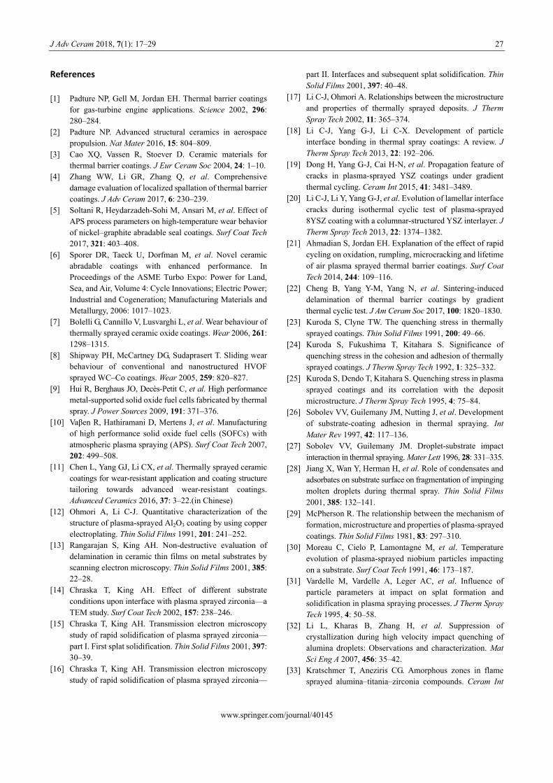
Fig. B Fracture surface morphology of polycrystalline and single-crystal 7YSZ splats on (a, b) Al2O3 and (c, d) 18YSZ substrates, respectively. Zigzag crack path and columnar grains with sharp corners were clearly observed in polycrystalline 7YSZ splats (a, b), while the cross sections of single-crystal 7YSZ splats were quite smooth.
J Adv Ceram 2018, 7(1): 17–29 27
References
[1] Padture NP, Gell M, Jordan EH. Thermal barrier coatings for gas-turbine engine applications. Science 2002, 296: 280–284.
[2] Padture NP. Advanced structural ceramics in aerospace propulsion. Nat Mater 2016, 15: 804–809.
[3] Cao XQ, Vassen R, Stoever D. Ceramic materials for thermal barrier coatings. J Eur Ceram Soc 2004, 24: 1–10.
[4] Zhang WW, Li GR, Zhang Q, et al. Comprehensive damage evaluation of localized spallation of thermal barrier coatings. J Adv Ceram 2017, 6: 230–239.
[5] Soltani R, Heydarzadeh-Sohi M, Ansari M, et al. Effect of APS process parameters on high-temperature wear behavior of nickel–graphite abradable seal coatings. Surf Coat Tech 2017, 321: 403–408.
[6] Sporer DR, Taeck U, Dorfman M, et al. Novel ceramic abradable coatings with enhanced performance. In Proceedings of the ASME Turbo Expo: Power for Land, Sea, and Air, Volume 4: Cycle Innovations; Electric Power; Industrial and Cogeneration; Manufacturing Materials and Metallurgy, 2006: 1017–1023.
[7] Bolelli G, Cannillo V, Lusvarghi L, et al. Wear behaviour of thermally sprayed ceramic oxide coatings. Wear 2006, 261: 1298–1315.
[8] Shipway PH, McCartney DG, Sudaprasert T. Sliding wear behaviour of conventional and nanostructured HVOF sprayed WC–Co coatings. Wear 2005, 259: 820–827.
[9] Hui R, Berghaus JO, Decès-Petit C, et al. High performance metal-supported solid oxide fuel cells fabricated by thermal spray. J Power Sources 2009, 191: 371–376.
[10] Vaβen R, Hathiramani D, Mertens J, et al. Manufacturing of high performance solid oxide fuel cells (SOFCs) with atmospheric plasma spraying (APS). Surf Coat Tech 2007, 202: 499–508.
[11] Chen L, Yang GJ, Li CX, et al. Thermally sprayed ceramic coatings for wear-resistant application and coating structure tailoring towards advanced wear-resistant coatings. Advanced Ceramics 2016, 37: 3–22.(in Chinese)
[12] Ohmori A, Li C-J. Quantitative characterization of the structure of plasma-sprayed Al2O3 coating by using copper electroplating. Thin Solid Films 1991, 201: 241–252.
[13] Rangarajan S, King AH. Non-destructive evaluation of delamination in ceramic thin films on metal substrates by scanning electron microscopy. Thin Solid Films 2001, 385: 22–28.
[14] Chraska T, King AH. Effect of different substrate conditions upon interface with plasma sprayed zirconia—a TEM study. Surf Coat Tech 2002, 157: 238–246.
[15] Chraska T, King AH. Transmission electron microscopy study of rapid solidification of plasma sprayed zirconia— part I. First splat solidification. Thin Solid Films 2001, 397: 30–39.
[16] Chraska T, King AH. Transmission electron microscopy study of rapid solidification of plasma sprayed zirconia—
part II. Interfaces and subsequent splat solidification. Thin Solid Films 2001, 397: 40–48.
[17] Li C-J, Ohmori A. Relationships between the microstructure and properties of thermally sprayed deposits. J Therm Spray Tech 2002, 11: 365–374.
[18] Li C-J, Yang G-J, Li C-X. Development of particle interface bonding in thermal spray coatings: A review. J Therm Spray Tech 2013, 22: 192–206.
[19] Dong H, Yang G-J, Cai H-N, et al. Propagation feature of cracks in plasma-sprayed YSZ coatings under gradient thermal cycling. Ceram Int 2015, 41: 3481–3489.
[20] Li C-J, Li Y, Yang G-J, et al. Evolution of lamellar interface cracks during isothermal cyclic test of plasma-sprayed 8YSZ coating with a columnar-structured YSZ interlayer. J Therm Spray Tech 2013, 22: 1374–1382.
[21] Ahmadian S, Jordan EH. Explanation of the effect of rapid cycling on oxidation, rumpling, microcracking and lifetime of air plasma sprayed thermal barrier coatings. Surf Coat Tech 2014, 244: 109–116.
[22] Cheng B, Yang Y-M, Yang N, et al. Sintering-induced delamination of thermal barrier coatings by gradient thermal cyclic test. J Am Ceram Soc 2017, 100: 1820–1830.
[23] Kuroda S, Clyne TW. The quenching stress in thermally sprayed coatings. Thin Solid Films 1991, 200: 49–66.
[24] Kuroda S, Fukushima T, Kitahara S. Significance of quenching stress in the cohesion and adhesion of thermally sprayed coatings. J Therm Spray Tech 1992, 1: 325–332.
[25] Kuroda S, Dendo T, Kitahara S. Quenching stress in plasma sprayed coatings and its correlation with the deposit microstructure. J Therm Spray Tech 1995, 4: 75–84.
[26] Sobolev VV, Guilemany JM, Nutting J, et al. Development of substrate-coating adhesion in thermal spraying. Int Mater Rev 1997, 42: 117–136.
[27] Sobolev VV, Guilemany JM. Droplet-substrate impact interaction in thermal spraying. Mater Lett 1996, 28: 331–335.
[28] Jiang X, Wan Y, Herman H, et al. Role of condensates and adsorbates on substrate surface on fragmentation of impinging molten droplets during thermal spray. Thin Solid Films 2001, 385: 132–141.
[29] McPherson R. The relationship between the mechanism of formation, microstructure and properties of plasma-sprayed coatings. Thin Solid Films 1981, 83: 297–310.
[30] Moreau C, Cielo P, Lamontagne M, et al. Temperature evolution of plasma-sprayed niobium particles impacting on a substrate. Surf Coat Tech 1991, 46: 173–187.
[31] Vardelle M, Vardelle A, Leger AC, et al. Influence of particle parameters at impact on splat formation and solidification in plasma spraying processes. J Therm Spray Tech 1995, 4: 50–58.
[32] Li L, Kharas B, Zhang H, et al. Suppression of crystallization during high velocity impact quenching of alumina droplets: Observations and characterization. Mat Sci Eng A 2007, 456: 35–42.
[33] Kratschmer T, Aneziris CG. Amorphous zones in flame sprayed alumina–titania–zirconia compounds. Ceram Int
www.springer.com/journal/40145
28 J Adv Ceram 2018, 7(1): 17–29
2011, 37: 181–188. [34] Chen L, Yang G-J. Anomalous epitaxial growth in
thermally sprayed YSZ and LZ splats. J Therm Spray Tech 2017, 26: 1168–1182.
[35] Chen L, Yang G-J, Li C-X. Formation of lamellar pores for splats via interfacial or sub-interfacial delamination at chemically bonded region. J Therm Spray Tech 2017, 26: 315–326.
[36] Chen L, Yang G-J, Li C-X, et al. Hierarchical formation of intrasplat cracks in thermal spray ceramic coatings. J Therm Spray Tech 2016, 25: 959–970.
[37] Chen L, Yang G-J, Li C-X, et al. Edge effect on crack patterns in thermally sprayed ceramic splats. J Therm Spray Tech 2017, 26: 302–314.
[38] Matejicek J, Sampath S. In situ measurement of residual stresses and elastic moduli in thermal sprayed coatings: Part 1: apparatus and analysis. Acta Mater 2003, 51: 863–872.
[39] Matejicek J, Sampath S, Brand PC, et al. Quenching, thermal and residual stress in plasma sprayed deposits: NiCrAlY and YSZ coatings. Acta Mater 1999, 47: 607–617.
[40] Vassen R, Cao X, Tietz F, et al. Zirconates as new materials for thermal barrier coatings. J Am Ceram Soc 2000, 83: 2023–2028.
[41] Sampath S, Jiang XY, Matejicek J, et al. Substrate temperature effects on splat formation, microstructure development and properties of plasma sprayed coatings Part I: Case study for partially stabilized zirconia. Mat Sci Eng A 1999, 272: 181–188.
[42] Jiang X, Matejicek J, Sampath S. Substrate temperature effects on the splat formation, microstructure development and properties of plasma sprayed coatings Part II: Case study for molybdenum. Mat Sci Eng B 1999, 272: 189–198.
[43] Sampath S, Jiang X. Splat formation and microstructure development during plasma spraying: Deposition temperature effects. Mat Sci Eng A 2001, 304–306: 144–150.
[44] Hao S, Li C-J, Yang G-J. Influence of deposition temperature on the microstructures and properties of plasma-sprayed Al2O3 coatings. J Therm Spray Tech 2011, 20: 160–169.
[45] Zhu X, Mills KL, Peters PR, et al. Fabrication of reconfigurable protein matrices by cracking. Nat Mater 2005, 4: 403–406.
[46] Huh D, Mills KL, Zhu X, et al. Tuneable elastomeric nanochannels for nanofluidic manipulation. Nat Mater 2007, 6: 424–428.
[47] Kim BC, Moraes C, Huang J, et al. Fracture-based fabrication of normally closed, adjustable, and fully reversible microscale fluidic channels. Small 2014, 10: 4020–4029.
[48] Kim BC, Moraes C, Huang J, et al. Fracture-based micro- and nanofabrication for biological applications. Biomater Sci 2014, 2: 288–296.
[49] Chen L, Yang GJ. Imaging the slit pores under the delaminated films by white light interference. J Therm
Spray Tech 2018, in press. [50] Levi CG. Metastability and microstructure evolution in the
synthesis of inorganics from precursors. Acta Mater 1998, 46: 787–800.
[51] Pascual C, Durán P. Subsolidus phase equilibia and ordering of the system ZrO2–Y2O3. J Am Ceram Soc 1983, 66: 23–27.
[52] Matejicek J, Sampath S, Gilmore D, et al. In situ measurement of residual stresses and elastic moduli in thermal sprayed coatings: Part 2: Processing effects on properties of Mo coatings. Acta Mater 2003, 51: 873–885.
[53] Matejicek J, Sampath S. Intrinsic residual stresses in single splats produced by thermal spray processes. Acta Mater 2001, 49: 1993–1999.
[54] Suo Z, Hutchinson JW. Steady-state cracking in brittle substrates beneath adherent films. Int J Solids Struct 1989, 25: 1337–1353.
[55] Suo Z, Hutchinson JW. Interface crack between two elastic layers. Int J Fract 1990, 43: 1–18.
[56] Ye T, Suo Z, Evans AG. Thin film cracking and the roles of substrate and interface. Int J Solids Struct 1992, 29: 2639–2648.
[57] Hutchinson JW, Suo Z. Mixed mode cracking in layered materials. Advances in Applied Mechanics 1992, 29: 63–191.
[58] Bagchi A, Evans AG. The mechanics and physics of thin film decohesion and its measurement. Interface Sci 1996, 3: 169–193.
[59] Evans AG, Hutchinson JW. The thermomechanical integrity of thin films and multilayers. Acta Metall Mater 1995, 43: 2507–2530.
[60] Thouless MD, Cao HC, Mataga PA. Delamination from surface cracks in composite materials. J Mater Sci 1989, 24: 1406–1412.
[61] Hutchinson JW. Stresses and failure modes in thin films and multilayers. Lecture Note, 1996. Available at https://www.seas.harvard.edu/hutchinson/papers/462-5.pdf.
[62] Yin HM, Paulino GH, Buttlar WG. An explicit elastic solution for a brittle film with periodic cracks. Int J Fract 2008, 153: 39–52.
[63] Huang R, Prévost JH, Huang ZY, et al. Channel-cracking of thin films with the extended finite element method. Eng Fract Mech 2003, 70: 2513–2526.
[64] Liu XH, Shaw TM, Lane MW, et al. Channel cracking in low-k films on patterned multi-layers. In Proceedings of the IEEE 2004 International Interconnect Technology Conference, 2004: 93–95.
[65] He MY, Hsueh CH, Becher PF. Deflection versus penetration of a wedge-loaded crack: Effects of branch-crack length and penetrated-layer width. Compos Part B-Eng 2000, 31: 299–308.
[66] Zhang Z, Suo Z. Split singularities and the competition between crack penetration and debond at a bimaterial interface. Int J Solids Struct 2007, 44: 4559–4573.
[67] Mei H, Pang Y, Huang R. Influence of interfacial
www.springer.com/journal/40145
J Adv Ceram 2018, 7(1): 17–29 29
www.springer.com/journal/40145
delamination on channel cracking of elastic thin films. Int J Fract 2007, 148: 331–342.
[68] Schmauder S, Meyer M. Correlation between Dundurs’ parameters and elastic constants. Z Metallkd 1992, 83: 524–527.
[69] Beuth JL. Cracking of thin bonded films in residual tension. Int J Solids Struct 1992, 29: 1657–1675.
[70] Krabbe M. Crack mechanisms and crack interaction in thin films. Technical Reports Mechanical Engineering, 2012. Available at https://tidsskrift.dk/me/article/view/21125/18625.
[71] Robertson J, Manning MI. Limits to adherence of oxide scales. Mater Sci Tech 1990, 6: 81–92.
[72] Shenoy VB, Schwartzman AF, Freund LB. Crack patterns in brittle thin films. Int J Fract 2001, 109: 29–45.
[73] Thouless MD. Crack spacing in brittle films on elastic substrates. J Am Ceram Soc 1990, 73: 2144–2146.
[74] Thouless MD, Olsson E, Gupta A. Cracking of brittle films on elastic substrates. Acta Metall Mater 1992, 40: 1287–1292.
[75] Thouless MD, Li Z, Douville NJ, et al. Periodic cracking of films supported on compliant substrates. J Mech Phys Solids 2011, 59: 1927–1937.
[76] Xia ZC, Hutchinson JW. Crack patterns in thin films. J Mech Phys Solids 2000, 48: 1107–1131.
[77] Nahta R, Moran B. Crack spacing in brittle films on dissimilar planar and axisymmetric elastic substrates. Eng Fract Mech 1995, 52: 513–524.
[78] Zhang T-Y, Zhao M-H. Equilibrium depth and spacing of cracks in a tensile residual stressed thin film deposited on a brittle substrate. Eng Fract Mech 2002, 69: 589–596.
[79] Nahta R, Moran B. Film cracking and debonding in a coated fiber. Int J Fract 1996, 79: 351–372.
[80] Bergman TL, Laing AS, Incropera FP, et al. Fundamentals of Heat and Mass Transfer, 7th edn. John Wiley & Sons Inc., 2011.
Open Access The articles published in this journal are distributed under the terms of the Creative Commons Attribution 4.0 International License (http://creativecommons.org/licenses/by/ 4.0/), which permits unrestricted use, distribution, and reproduction in any medium, provided you give appropriate credit to the original author(s) and the source, provide a link to the Creative Commons license, and indicate if changes were made.