Embed Size (px)
Citation preview
61©2005 Cooper Bussmann
Transformers — 600V or Less
Equipment Protection
The requirements of 450.3 cover only transformer protection. In practice, othercomponents must be considered in applying circuit overcurrent protection. Forcircuits with transformers, requirements for conductor protection per Articles240 and 310 and for panelboards per Article 408, must be observed. Refer to240.4(F), 240.21(B)(3), 240.21(C), 408.36(A) & (B).
Primary Fuse Protection Only [450.3(B)] (See Figure below) If secondary fuseprotection is not provided (as discussed in the next Section) then the primaryfuses must not be sized larger than as shown below.
Individual transformer primary fuses are not necessary where the primary circuit fuse provides this protection.
Fuse must not be larger than 125% of transformer primary F.L.A.When no transformer secondary protection is provided(exceptions as noted above).
Primary600V
or Less
Secondary600V
or Less
TRANSFORMER No SecondaryProtection
Individual primary transformer fuse or primary feeder fusemust not be larger than 250% of primary full-load currentwhen secondary fuses are provided at 125%, exceptas noted above.
Primary600V
Or Less
Secondary600V
Or Less
TRANSFORMER
Secondary Fuses at 125%of secondary F.L.A. exceptas noted above.
Primary Fuse OnlyPrimary Current Primary Fuse Rating9 amps or more 125% or next higher standard rating if
125% does not correspond to a standard fuse size.
2 amps to 9 amps 167% maximumLess than 2 amps 300% maximum
Primary and Secondary FusesSecondary Current Primary Fuse Rating Secondary Fuse Rating9 amps or more 250% max. 125% or next higher standard
rating if 125% does not corre-spond to a standard fuse size
Less than 9 amps 250% max. 167% max.
Note: Section 450.3 requirements pertain only to transformer protection. Additionalcircuit overcurrent protection for conductors or panelboards may be required perArticles 240, 310, 408, 430.72.
* Primary Fuse (600V or less) and Secondary Fuse (600V or less). If secondary (600V or less) fuses are sized not greater than 125% of trans-former secondary current, individual transformer fuses are not required in theprimary (600V or less) provided the primary feeder fuses are not larger than250% of the transformer rated primary current. [See Note 3 of Table 450.3(B)for overcurrent protection requirements of thermally protected transformers].
Note: Transformer overload protection will be sacrificed by using overcurrentprotective devices sized much greater than the transformer F.L.A. The limits of150%, 167%, 250% and 300% may not adequately protect transformers. It issuggested that for the highest degree of transformer overload protection thefuse size should be within 125% of the transformer full-load amps.
Normal magnetizing inrush currents for power transformers can range from 10times to 12 times the transformer full load current, for up to 6 cycles, and ashigh as 25 times transformer full load current at 0.01 seconds. Some
transformers may have inrush magnitudes substantially greater. Severe inrushshould be compared with melting times to assure that unnecessary opening ofthe device does not occur.
There is a wide fuse amp rating range available to properly protect transformers. Fusetron Class RK5 and Low-Peak Class RK1 dual-elementfuses can be sized on the transformer primary and/or secondary rated at125% of the transformer F.L.A. These dual-element fuses have sufficient time-delay to withstand the high magnetizing inrush currents of transformers. Thereis a wide amp rating selection in the 0 to 15A range for these dual-elementfuses to provide protection for even small control transformers.
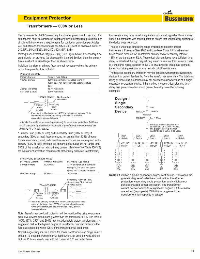
The required secondary protection may be satisfied with multiple overcurrentdevices that protect feeders fed from the transformer secondary. The total amprating of these multiple devices may not exceed the allowed value of a singlesecondary overcurrent device. If this method is chosen, dual-element, time-delay fuse protection offers much greater flexibility. Note the following examples:
Design 1 utilizes a single secondary overcurrent device. It provides the
greatest degree of selective coordination, transformer
protection, secondary cable protection, and switchboard/
panelboard/load center protection. The transformer
cannot be overloaded to a significant degree if future loads
are added (improperly). With this arrangement the
transformer’s full capacity is utilized.
62 ©2005 Cooper Bussmann
Transformers — 600V or Less
Equipment Protection
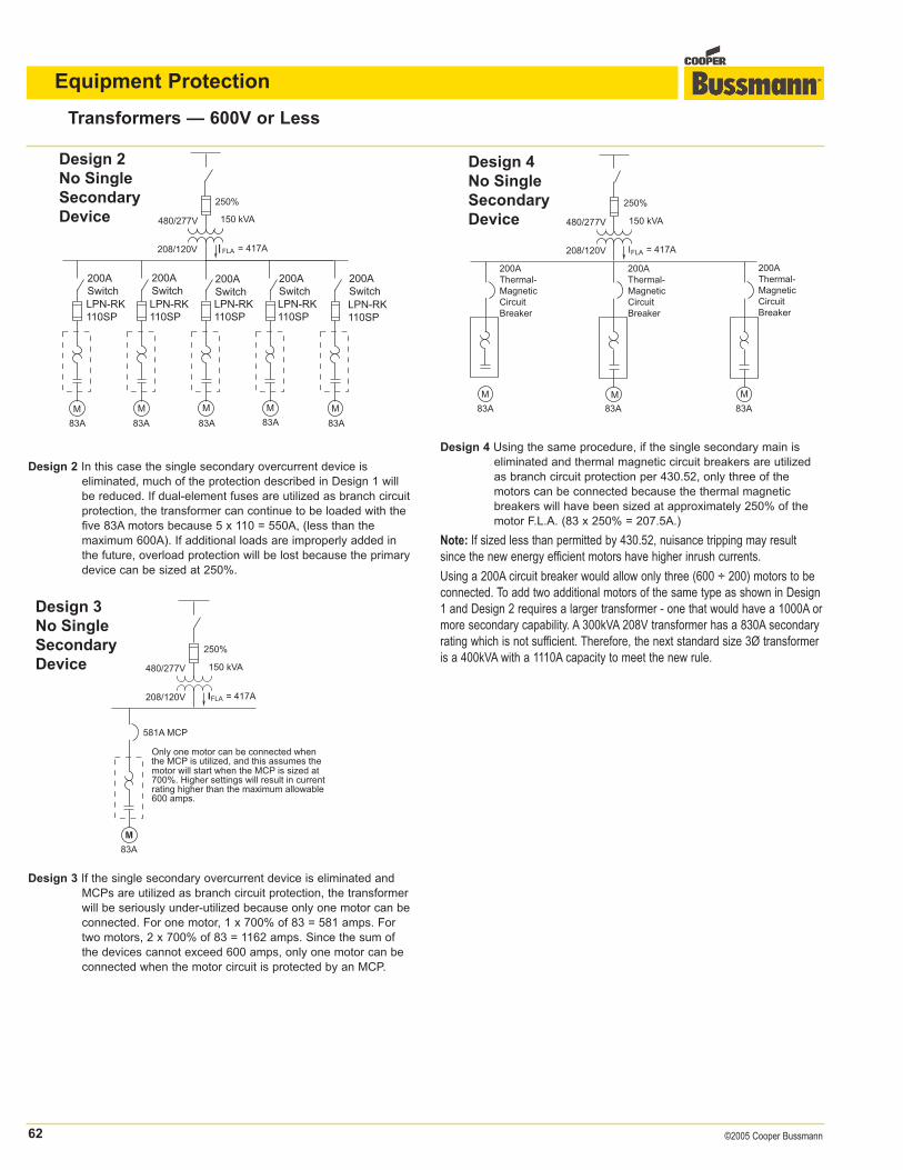
Design 2 In this case the single secondary overcurrent device is
eliminated, much of the protection described in Design 1 will
be reduced. If dual-element fuses are utilized as branch circuit
protection, the transformer can continue to be loaded with the
five 83A motors because 5 x 110 = 550A, (less than the
maximum 600A). If additional loads are improperly added in
the future, overload protection will be lost because the primary
device can be sized at 250%.
Design 3 If the single secondary overcurrent device is eliminated and
MCPs are utilized as branch circuit protection, the transformer
will be seriously under-utilized because only one motor can be
connected. For one motor, 1 x 700% of 83 = 581 amps. For
two motors, 2 x 700% of 83 = 1162 amps. Since the sum of
the devices cannot exceed 600 amps, only one motor can be
connected when the motor circuit is protected by an MCP.
Design 4 Using the same procedure, if the single secondary main is
eliminated and thermal magnetic circuit breakers are utilized
as branch circuit protection per 430.52, only three of the
motors can be connected because the thermal magnetic
breakers will have been sized at approximately 250% of the
motor F.L.A. (83 x 250% = 207.5A.)
Note: If sized less than permitted by 430.52, nuisance tripping may resultsince the new energy efficient motors have higher inrush currents.
Using a 200A circuit breaker would allow only three (600 ÷ 200) motors to beconnected. To add two additional motors of the same type as shown in Design1 and Design 2 requires a larger transformer - one that would have a 1000A ormore secondary capability. A 300kVA 208V transformer has a 830A secondaryrating which is not sufficient. Therefore, the next standard size 3Ø transformeris a 400kVA with a 1110A capacity to meet the new rule.
63©2005 Cooper Bussmann
Transformers — Over 600V
Equipment Protection
Primary and Secondary Protection
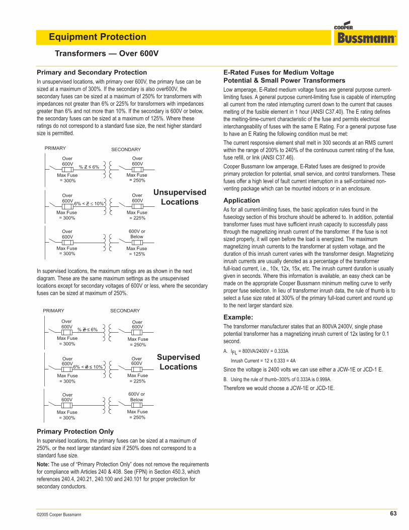
In unsupervised locations, with primary over 600V, the primary fuse can besized at a maximum of 300%. If the secondary is also over600V, the secondary fuses can be sized at a maximum of 250% for transformers withimpedances not greater than 6% or 225% for transformers with impedancesgreater than 6% and not more than 10%. If the secondary is 600V or below,the secondary fuses can be sized at a maximum of 125%. Where these ratings do not correspond to a standard fuse size, the next higher standardsize is permitted.
% Z ≤ 6% –
Max Fuse= 250%
Over600V
Over600V
Max Fuse= 300%
Max Fuse= 225%
Over600V
Over600V
Max Fuse= 300%
Max Fuse= 125%
600V or Below
Over600V
Max Fuse= 300%
PRIMARY SECONDARY
6% < Z ≤ 10%–
UnsupervisedLocations
Over600V
Max Fuse= 300%
PRIMARY SECONDARY
600V
600V 600V
600V600V orBelow
Over
Over Over
Over
Max Fuse= 300%
Max Fuse= 300%
Max Fuse= 225%
Max Fuse= 250%
Max Fuse= 250%
SupervisedLocations
% Z ≤ 6%
6% < Z ≤ 10%
In supervised locations, the maximum ratings are as shown in the next diagram. These are the same maximum settings as the unsupervised locations except for secondary voltages of 600V or less, where the secondaryfuses can be sized at maximum of 250%.
Primary Protection Only
In supervised locations, the primary fuses can be sized at a maximum of250%, or the next larger standard size if 250% does not correspond to a standard fuse size.
Note: The use of “Primary Protection Only” does not remove the requirementsfor compliance with Articles 240 & 408. See (FPN) in Section 450.3, which references 240.4, 240.21, 240.100 and 240.101 for proper protection for secondary conductors.
E-Rated Fuses for Medium Voltage
Potential & Small Power Transformers
Low amperage, E-Rated medium voltage fuses are general purpose current-limiting fuses. A general purpose current-limiting fuse is capable of interruptingall current from the rated interrupting current down to the current that causesmelting of the fusible element in 1 hour (ANSI C37.40). The E rating definesthe melting-time-current characteristic of the fuse and permits electrical interchangeability of fuses with the same E Rating. For a general purpose fuseto have an E Rating the following condition must be met:
The current responsive element shall melt in 300 seconds at an RMS currentwithin the range of 200% to 240% of the continuous current rating of the fuse,fuse refill, or link (ANSI C37.46).
Cooper Bussmann low amperage, E-Rated fuses are designed to provide primary protection for potential, small service, and control transformers. Thesefuses offer a high level of fault current interruption in a self-contained non-venting package which can be mounted indoors or in an enclosure.
Application
As for all current-limiting fuses, the basic application rules found in the fuseology section of this brochure should be adhered to. In addition, potentialtransformer fuses must have sufficient inrush capacity to successfully passthrough the magnetizing inrush current of the transformer. If the fuse is notsized properly, it will open before the load is energized. The maximum magnetizing inrush currents to the transformer at system voltage, and theduration of this inrush current varies with the transformer design. Magnetizinginrush currents are usually denoted as a percentage of the transformer full-load current, i.e., 10x, 12x, 15x, etc. The inrush current duration is usuallygiven in seconds. Where this information is available, an easy check can bemade on the appropriate Cooper Bussmann minimum melting curve to verifyproper fuse selection. In lieu of transformer inrush data, the rule of thumb is toselect a fuse size rated at 300% of the primary full-load current and round upto the next larger standard size.
Example:
The transformer manufacturer states that an 800VA 2400V, single phasepotential transformer has a magnetizing inrush current of 12x lasting for 0.1second.
A. IFL = 800VA/2400V = 0.333A
Inrush Current = 12 x 0.333 = 4A
Since the voltage is 2400 volts we can use either a JCW-1E or JCD-1 E.
B. Using the rule of thumb–300% of 0.333A is 0.999A.
Therefore we would choose a JCW-1E or JCD-1E.
64 ©2005 Cooper Bussmann
Transformers — Over 600V
Equipment Protection
Typical Potential Transformer Connections
The typical potential transformer connections encountered in industry can begrouped into two categories:
1. Those connections which require the fuse to pass only the magnetizing inrush of one potential transformer
2. Those connections which must pass the magnetizing inrush of more than one potential transformer
E-Rated Fuses for Medium Voltage
Transformers & Feeders
Cooper Bussmann E-Rated medium voltage fuses are general purpose current-limiting fuses. A general purpose current-limiting fuse is capable ofinterrupting all currents from the rated interrupted current down to the currentthat causes melting of the fusible element in 1 hour (ANSI C37.40). The fusescarry either an ‘E’ or an ‘X’ rating which defines the melting-time-current characteristic of the fuse. The ratings are used to allow electrical interchangeability among different manufacturers’ fuses.
For a general purpose fuse to have an E rating, the following conditions mustbe met:
1. 100E and below - the fuse element must melt in 300 seconds at 200% to 240% ofits rating (ANSI C37.46).
2. Above 100E - the fuse element must melt in 600 seconds at 220% to 264% of itsrating (ANSI C37.46).
A fuse with an ‘X’ rating does not meet the electrical inter-changeability for an‘E’ rated fuse but offers the user other ratings that may provide better protection for a particular application.
Application
Transformer protection is the most popular application of E-Rated fuses. Thefuse is applied to the primary of the transformer and is used solely to preventrupture of the transformer due to short circuits. It is important, therefore, tosize the fuse so that it does not clear on system inrush or permissible overloadcurrents. See section on transformers over 600V for applicable sizing recom-mendations. Magnetizing inrush must also be considered when sizing a fuse.In general, power transformers have a magnetizing inrush current of 12x thefull-load rating for a duration of 1⁄10 second.
Cooper Bussmann E-Rated Medium Voltage Fuse.
186 ©2005 Cooper Bussmann
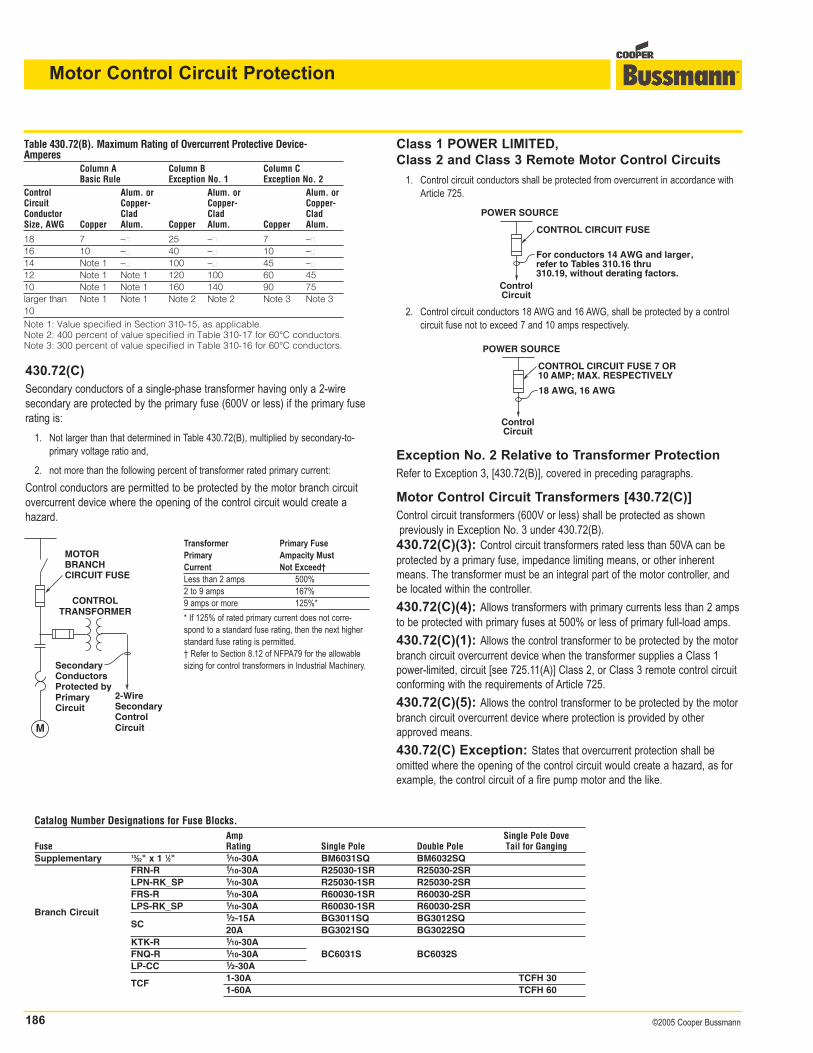
430.72(C)
Secondary conductors of a single-phase transformer having only a 2-wire secondary are protected by the primary fuse (600V or less) if the primary fuserating is:
1. Not larger than that determined in Table 430.72(B), multiplied by secondary-to-primary voltage ratio and,
2. not more than the following percent of transformer rated primary current:
Control conductors are permitted to be protected by the motor branch circuitovercurrent device where the opening of the control circuit would create a hazard.
Motor Control Circuit Protection
Table 430.72(B). Maximum Rating of Overcurrent Protective Device-Amperes
Column A Column B Column CBasic Rule Exception No. 1 Exception No. 2
Control Alum. or Alum. or Alum. orCircuit Copper- Copper- Copper-Conductor Clad Clad CladSize, AWG Copper Alum. Copper Alum. Copper Alum.
18 7 – 25 – 7 –16 10 – 40 – 10 –14 Note 1 – 100 – 45 –12 Note 1 Note 1 120 100 60 4510 Note 1 Note 1 160 140 90 75larger than Note 1 Note 1 Note 2 Note 2 Note 3 Note 310Note 1: Value specified in Section 310-15, as applicable.Note 2: 400 percent of value specified in Table 310-17 for 60°C conductors.Note 3: 300 percent of value specified in Table 310-16 for 60°C conductors.
M
MOTORBRANCH CIRCUIT FUSE
CONTROL TRANSFORMER
SecondaryConductorsProtected byPrimaryCircuit
2-WireSecondaryControlCircuit
CONTROL CIRCUIT FUSE
For conductors 14 AWG and larger,refer to Tables 310.16 thru310.19, without derating factors.
POWER SOURCE
ControlCircuit
CONTROL CIRCUIT FUSE 7 OR10 AMP; MAX. RESPECTIVELY
18 AWG, 16 AWG
POWER SOURCE
ControlCircuit
Transformer Primary FusePrimary Ampacity MustCurrent Not Exceed†Less than 2 amps 500%2 to 9 amps 167%9 amps or more 125%*
* If 125% of rated primary current does not corre-spond to a standard fuse rating, then the next higherstandard fuse rating is permitted.† Refer to Section 8.12 of NFPA79 for the allowablesizing for control transformers in Industrial Machinery.
Class 1 POWER LIMITED,
Class 2 and Class 3 Remote Motor Control Circuits
1. Control circuit conductors shall be protected from overcurrent in accordance withArticle 725.
2. Control circuit conductors 18 AWG and 16 AWG, shall be protected by a controlcircuit fuse not to exceed 7 and 10 amps respectively.
Exception No. 2 Relative to Transformer Protection
Refer to Exception 3, [430.72(B)], covered in preceding paragraphs.
Motor Control Circuit Transformers [430.72(C)]
Control circuit transformers (600V or less) shall be protected as shownpreviously in Exception No. 3 under 430.72(B).430.72(C)(3): Control circuit transformers rated less than 50VA can beprotected by a primary fuse, impedance limiting means, or other inherentmeans. The transformer must be an integral part of the motor controller, andbe located within the controller.
430.72(C)(4): Allows transformers with primary currents less than 2 ampsto be protected with primary fuses at 500% or less of primary full-load amps.
430.72(C)(1): Allows the control transformer to be protected by the motorbranch circuit overcurrent device when the transformer supplies a Class 1power-limited, circuit [see 725.11(A)] Class 2, or Class 3 remote control circuitconforming with the requirements of Article 725.
430.72(C)(5): Allows the control transformer to be protected by the motorbranch circuit overcurrent device where protection is provided by otherapproved means.
430.72(C) Exception: States that overcurrent protection shall be omitted where the opening of the control circuit would create a hazard, as forexample, the control circuit of a fire pump motor and the like.

187©2005 Cooper Bussmann
The following Selection Guide Tables simplify and permit easy application offuses for the protection of the motor control circuits in accordance within theNational Electrical Code®. Apply fuses per Table 1 for control circuit without acontrol transformer (see Circuit Diagrams 1 and 2). Apply fuses per Table 2 fora control circuit with a control transformer (see Circuit Diagrams 3 and 4).
Motor Control Circuit Protection
Table 2. Fuse Selection Guide–Control Circuit With Control Transformer (See Circuit Diagrams 3 and 4)Control Vpri/Vsec Ipri Isec
1Fuse C Fuse D or EXfmr (Volts) (Amps) (Amps)
2Req’d. If 4,5Maximum Required if BCPD and Fuse C (When Recommended AmpsRating BCPD Exceeds Amps Provided) Exceed These Amp Values
These Amps 18 AWG 16 AWG 14 AWG 12 AWG Time Non-TimeValues Wire Wire Wire Wire Delay1 Delay3
480/120 0.05 0.21 6See 0.25 0.25 0.25 0.25 0.25 0.25 0.60
25VA 480/24 0.05 1.00 430-72(C) 0.25 0.25 0.25 0.25 0.25 1.25 3.0240/120 0.10 0.21 Except. 1 0.50 0.50 0.50 0.50 0.50 0.25 0.60240/24 0.10 1.00 0.50 0.50 0.50 0.50 0.50 1.25 3.0480/120 0.10 0.42 0.5 0.50 0.50 0.50 0.50 0.50 0.50 1.0
50VA 480/24 0.10 2.10 0.5 0.50 0.50 0.50 0.50 0.50 2.5 6.0240/120 0.21 0.42 1.0 1.0 1.0 1.0 1.0 1.0 0.50 1.0240/24 0.21 2.10 1.0 1.0 1.0 1.0 1.0 1.0 2.5 6.0480/120 0.21 0.83 1.0 1.0 1.0 1.0 1.0 1.0 1.0 2.0
100VA 480/24 0.21 4.20 1.0 1.0 1.0/.359 1.0/.509 1.0 1.0 5.0 12.07
240/120 0.42 0.83 2.0 2.0 2.0 2.0 2.0 2.0 1.0 2.0240/24 0.42 4.20 2.0 2.0 2.0/.709 2.0/1.09 2.0 2.0 5.0 12.07
480/120 0.31 1.25 1.5 1.5 1.5 1.5 1.5 1.5 1.50 3.50
150VA 480/24 0.31 6.25 1.5 1.5 — 1.5/0.59 1.5 1.5 7.50 15.07
240/120 0.62 1.25 3.0 3.0 3.0 3.0 3.0 3.0 1.50 3.50240/24 0.62 6.25 3.0 3.0 — 3.0/1.09 3.0 3.0 7.50 15.07
480/120 0.42 1.67 2.0 2.0 2.0/1.759 2.0 2.0 2.0 2.0 5.0
200VA 480/24 0.42 8.33 2.0 2.0 — — 2.0 2.0 10.0 20.08
240/120 0.84 1.67 4.0 4.0 4.0/3.59 2.0 4.0 4.0 2.0 5.0240/24 0.84 8.33 4.0 4.0 — — 4.0 4.0 10.0 20.08
1 Time-Delay Fuses: FNQ, FNW, FNM, FNA–Supplementary Type; FNQ-R, FRN-R, FRS-R, LPN-RK_SP, LPS-RK_SP, LPJ_SP, LP-CC, SC6 & above–Branch Circuit Fuses (Rejection Type).2 For exceptions, see 430.72(C).3 Non-Time-Delay Fuses: KTK, BAN, BAF, MIN, MIC–Supplementary Fuses; KTK-R, JJN, JJS, SC⁄Ω™-5–Branch Circuit Fuses (Rejection Types).4 These are maximum values as allowed by 430.72(C). Closer sizing at 125%-300% may be possible for better overload protection using time-delay branch circuit fuses.5 Fuse shall be a rejection type branch circuit fuse when withstand rating of controller is greater than 10,000 amps RMS symmetrical6 These transformers less than 50VA still need protection–either primary overcurrent protection, inherent protection, or the equivalent. Note that the primary conductors may be protectedas shown in Circuit 1 Table 1. 7 Minimum copper secondary control conductor for this application is 14 AWG. 8 Minimum copper secondary control conductor for this application is 12AWG.
9 Smaller value applied to Fuse "E".
Control Circuit Without Control Transformer (See Table 1)
Circuit 1 Circuit 2
Control Circuit With Control Transformer (See Table 2)
Circuit 3 Circuit 4
BCPD(Branch CircuitProtective Device)
Cop per ControlCon duct orRemaining WithinEnclosure
A
BCPD(Branch CircuitProtective Device)
CopperControlConductorExtendingBeyondEnclosure
B
CopperControlConductorExtendingBeyondEnclosure
BCPD(Branch CircuitProtective Device)
Copper ControlConductorRemaining WithinEnclosure
D
C
C
BCPD(Branch CircuitProtective Device)
E
C
C
188 ©2005 Cooper Bussmann
Motor Control Circuit Protection
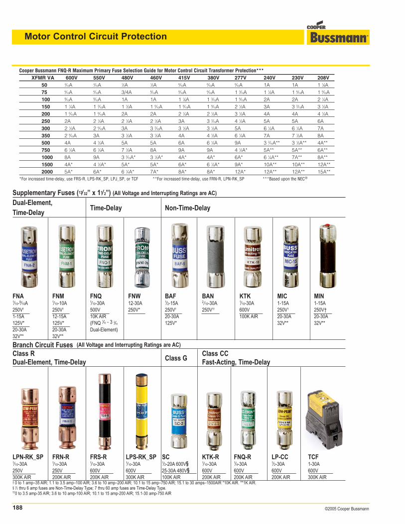
Supplementary Fuses (13/ 32” x 11/ 2”) (All Voltage and Interrupting Ratings are AC)
Dual-Element,Time-Delay Non-Time-Delay
Time-Delay
FNA FNM FNQ FNW BAF BAN KTK MIC MIN1/10-8/10A 1/10-10A 1/10-30A 12-30A 1/2-15A 2/10-30A 1/10-30A 1-15A 1-15A250V† 250V† 500V 250V* 250V† 250V†† 600V 250V† 250V†1-15A 12-15A 10K AIR 20-30A 100K AIR 20-30A 20-30A125V* 125V* (FNQ 1⁄10 - 3 2⁄10 125V* 32V** 32V**20-30A 20-30A Dual-Element)32V** 32V**
Branch Circuit Fuses (All Voltage and Interrupting Ratings are AC)
Class RClass G
Class CC Dual-Element, Time-Delay Fast-Acting, Time-Delay
LPN-RK_SP FRN-R FRS-R LPS-RK_SP SC KTK-R FNQ-R LP-CC TCF1/10-30A 1/10-30A 1/10-30A 1/10-30A 1/2-20A 600V§ 1/10-30A 1/4-30A 1/2-30A 1-30A250V 250V 600V 600V 25-30A 480V§ 600V 600V 600V 600V300K AIR 200K AIR 200K AIR 300K AIR 100K AIR 200K AIR 200K AIR 200K AIR 300K AIR† 0 to 1 amp–35 AIR; 1.1 to 3.5 amp–100 AIR; 3.6 to 10 amp–200 AIR; 10.1 to 15 amp–750 AIR; 15.1 to 30 amps–1500AIR *10K AIR. **1K AIR.§ 1/2 thru 6 amp fuses are Non-Time-Delay Type; 7 thru 60 amp fuses are Time-Delay Type.††0 to 3.5 amp-35 AIR; 3.6 to 10 amp-100 AIR; 10.1 to 15 amp-200 AIR; 15.1-30 amp-750 AIR
205©2005 Cooper Bussmann
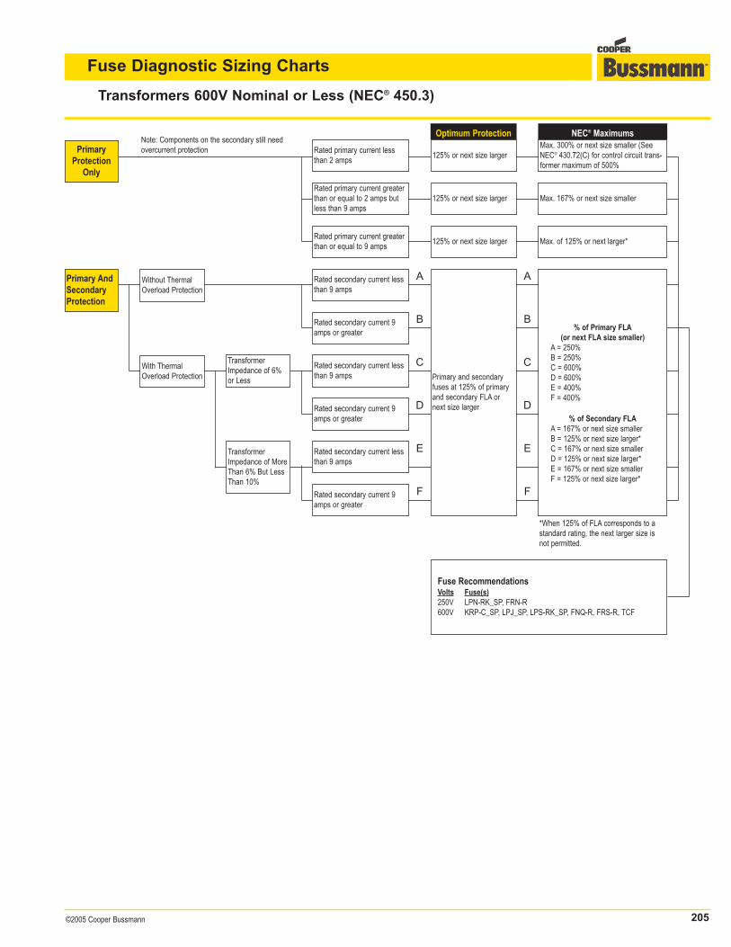
Fuse Diagnostic Sizing Charts
Transformers 600V Nominal or Less (NEC® 450.3)
PrimaryProtection
Only
*When 125% of FLA corresponds to astandard rating, the next larger size isnot permitted.
Primary AndSecondaryProtection
Optimum Protection
125% or next size larger
125% or next size larger
125% or next size larger Max. of 125% or next larger*
NEC® MaximumsMax. 300% or next size smaller (SeeNEC® 430.72(C) for control circuit trans-former maximum of 500%
Max. 167% or next size smaller
Rated secondary current 9amps or greater
Rated secondary current lessthan 9 amps
TransformerImpedance of 6%or Less
Rated secondary current 9amps or greater
Rated secondary current lessthan 9 amps
TransformerImpedance of MoreThan 6% But LessThan 10%
Rated secondary current lessthan 9 amps
Rated secondary current 9amps or greater
Without ThermalOverload Protection
With ThermalOverload Protection
Note: Components on the secondary still needovercurrent protection Rated primary current less
than 2 amps
Rated primary current greaterthan or equal to 9 amps
Rated primary current greaterthan or equal to 2 amps butless than 9 amps
Fuse RecommendationsVolts Fuse(s)250V LPN-RK_SP, FRN-R600V KRP-C_SP, LPJ_SP, LPS-RK_SP, FNQ-R, FRS-R, TCF
A A
B
C
D
E
F
B
C
D
E
F
Primary and secondaryfuses at 125% of primaryand secondary FLA ornext size larger
% of Primary FLA(or next FLA size smaller)
A = 250%B = 250%C = 600%D = 600%E = 400%F = 400%
% of Secondary FLAA = 167% or next size smallerB = 125% or next size larger*C = 167% or next size smallerD = 125% or next size larger*E = 167% or next size smallerF = 125% or next size larger*
206 ©2005 Cooper Bussmann
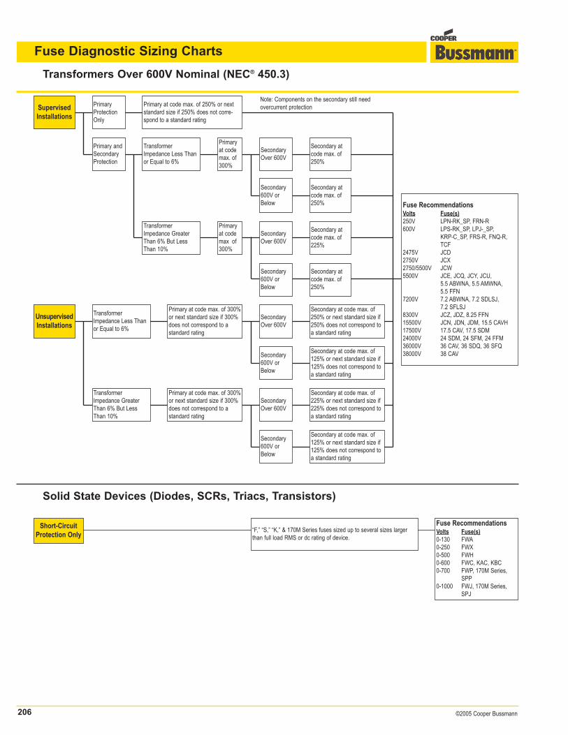
Fuse Diagnostic Sizing Charts
Transformers Over 600V Nominal (NEC® 450.3)
Solid State Devices (Diodes, SCRs, Triacs, Transistors)
SupervisedInstallations
UnsupervisedInstallations
Fuse RecommendationsVolts Fuse(s)250V LPN-RK_SP, FRN-R600V LPS-RK_SP, LPJ-_SP,
KRP-C_SP, FRS-R, FNQ-R,TCF
2475V JCD2750V JCX2750/5500V JCW5500V JCE, JCQ, JCY, JCU,
5.5 ABWNA, 5.5 AMWNA,5.5 FFN
7200V 7.2 ABWNA, 7.2 SDLSJ, 7.2 SFLSJ
8300V JCZ, JDZ, 8.25 FFN15500V JCN, JDN, JDM, 15.5 CAVH17500V 17.5 CAV, 17.5 SDM24000V 24 SDM, 24 SFM, 24 FFM36000V 36 CAV, 36 SDQ, 36 SFQ38000V 38 CAV
Note: Components on the secondary still needovercurrent protectionPrimary at code max. of 250% or next
standard size if 250% does not corre-spond to a standard rating
PrimaryProtectionOnly
TransformerImpedance Less Thanor Equal to 6%
Primaryat codemax. of300%
SecondaryOver 600V
Secondary atcode max. of250%
Secondary atcode max. of250%
Secondary atcode max. of225%
SecondaryOver 600V
Primaryat codemax. of300%
Secondary atcode max. of250%
SecondaryOver 600V
Primary at code max. of 300%or next standard size if 300%does not correspond to astandard rating
TransformerImpedance Less Thanor Equal to 6%
Primary at code max. of 300%or next standard size if 300%does not correspond to astandard rating
SecondaryOver 600V
Secondary at code max. of125% or next standard size if125% does not correspond toa standard rating
Secondary at code max. of225% or next standard size if225% does not correspond toa standard rating
Secondary at code max. of125% or next standard size if125% does not correspond toa standard rating
Secondary at code max. of250% or next standard size if250% does not correspond toa standard rating
TransformerImpedance GreaterThan 6% But LessThan 10%
Secondary600V orBelow
Secondary600V orBelow
Primary andSecondaryProtection
TransformerImpedance GreaterThan 6% But LessThan 10%
Secondary600V orBelow
Secondary600V orBelow
Short-CircuitProtection Only
“F,” “S,” “K,” & 170M Series fuses sized up to several sizes largerthan full load RMS or dc rating of device.
Fuse RecommendationsVolts Fuse(s)0-130 FWA0-250 FWX0-500 FWH0-600 FWC, KAC, KBC0-700 FWP, 170M Series,
SPP0-1000 FWJ, 170M Series,
SPJ


![Fuse Protection HR] No. 64229.0 Motion O size : 24.5cm 27 ... · PUMA SAFETY Fuse Motion Wns Protection Lining puma SAFETY . Title: emuneji_3a_omote_01 Created Date: 11/18/2014 5:20:44](https://img.pdfslide.net/doc/110x75/5f9754bad0bead5d24055f4d/fuse-protection-hr-no-642290-motion-o-size-245cm-27-puma-safety-fuse-motion.jpg)