Embed Size (px)
Citation preview
1 www.handsontec.com
Handson Technology
User Manual V1.2
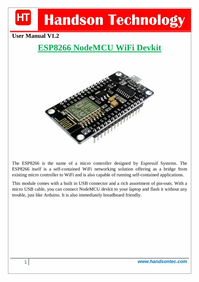
The ESP8266 is the name of a micro controller designed by Espressif Systems. The ESP8266 itself is a self-contained WiFi networking solution offering as a bridge from existing micro controller to WiFi and is also capable of running self-contained applications.
This module comes with a built in USB connector and a rich assortment of pin-outs. With a micro USB cable, you can connect NodeMCU devkit to your laptop and flash it without any trouble, just like Arduino. It is also immediately breadboard friendly.
ESP8266 NodeMCU WiFi Devkit
2 www.handsontec.com
Table of Contents 1. Specification:....................................................................................................................................................... 3
2. Pin Definition: ..................................................................................................................................................... 3
3. Using Arduino IDE ............................................................................................................................................... 3
3.1 Install the Arduino IDE 1.6.4 or greater ........................................................................................................ 4
3.2 Install the ESP8266 Board Package............................................................................................................... 4
3.3 Setup ESP8266 Support ............................................................................................................................... 5
3.4 Blink Test ..................................................................................................................................................... 7
3.5 Connecting via WiFi ..................................................................................................................................... 9
4. Flashing NodeMCU Firmware on the ESP8266 using Windows........................................................................... 12
4.1 Parts Required: ................................................................................................................................................ 12
4.2 Pin Assignment: ............................................................................................................................................... 12
4.3 Wiring: ............................................................................................................................................................ 13
4.4 Downloading NodeMCU Flasher for Windows ................................................................................................. 13
4.5 Flashing your ESP8266 using Windows ............................................................................................................ 13
5. Getting Started with the ESPlorer IDE ................................................................................................................ 15
5.1 Installing ESPlorer ............................................................................................................................................ 15
5.2 Schematics ...................................................................................................................................................... 18
5.3 Writing Your Lua Script .................................................................................................................................... 18
6. NodeMCU GPIO for Lua ......................................................................................................................................... 22
7. Web Resources: .................................................................................................................................................... 22
3 www.handsontec.com
1. Specification: • Voltage:3.3V. • Wi-Fi Direct (P2P), soft-AP. • Current consumption: 10uA~170mA. • Flash memory attachable: 16MB max (512K normal). • Integrated TCP/IP protocol stack. • Processor: Tensilica L106 32-bit. • Processor speed: 80~160MHz. • RAM: 32K + 80K. • GPIOs: 17 (multiplexed with other functions). • Analog to Digital: 1 input with 1024 step resolution. • +19.5dBm output power in 802.11b mode • 802.11 support: b/g/n. • Maximum concurrent TCP connections: 5.
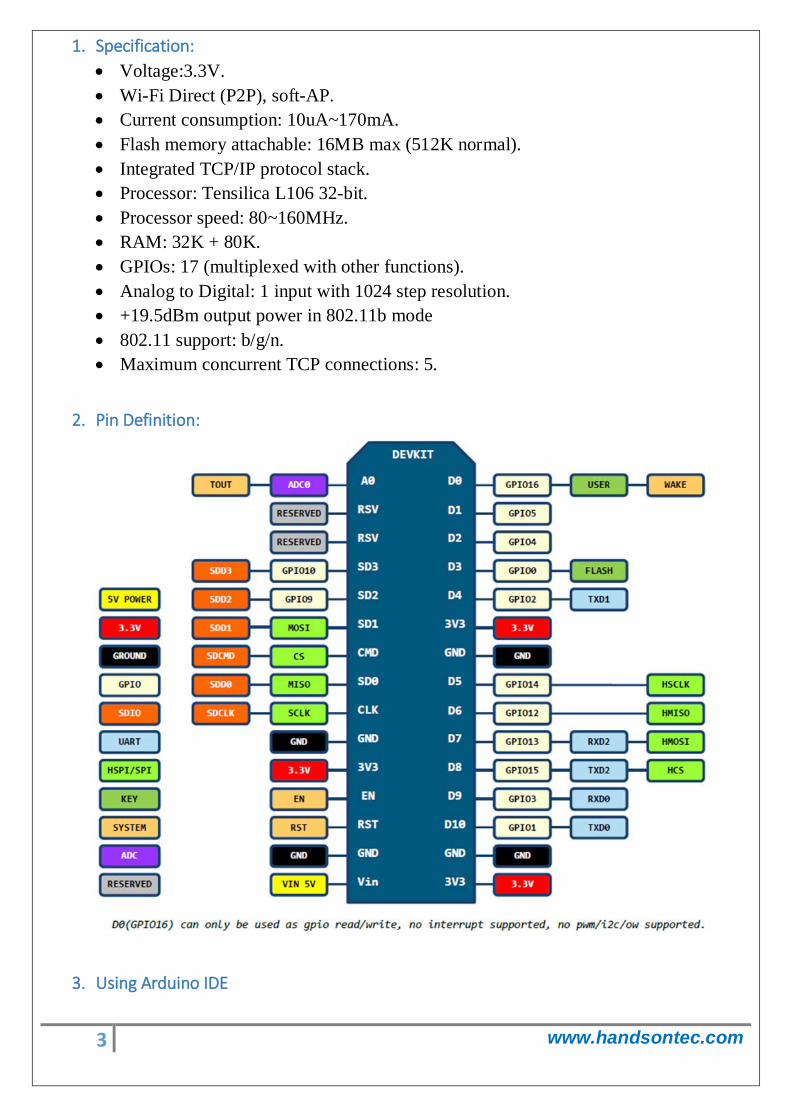
2. Pin Definition:
3. Using Arduino IDE
4 www.handsontec.com
The most basic way to use the ESP8266 module is to use serial commands, as the chip is basically a WiFi/Serial transceiver. However, this is not convenient. What we recommend is using the very cool Arduino ESP8266 project, which is a modified version of the Arduino IDE that you need to install on your computer. This makes it very convenient to use the ESP8266 chip as we will be using the well-known Arduino IDE. Following the below step to install ESP8266 library to work in Arduino IDE environment.
3.1 Install the Arduino IDE 1.6.4 or greater Download Arduino IDE from Arduino.cc (1.6.4 or greater) - don't use 1.6.2 or lower version! You can use your existing IDE if you have already installed it.
You can also try downloading the ready-to-go package from the ESP8266-Arduino project, if the proxy is giving you problems.
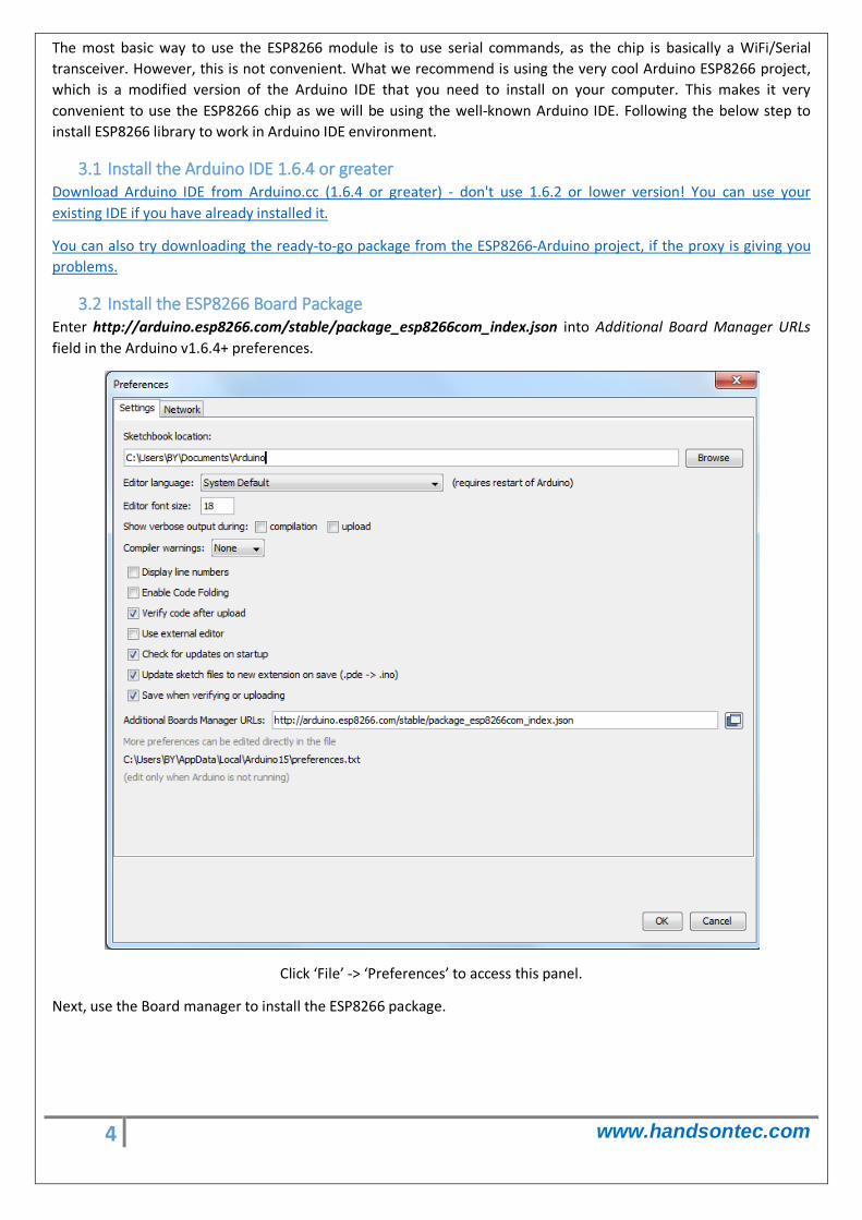
3.2 Install the ESP8266 Board Package Enter http://arduino.esp8266.com/stable/package_esp8266com_index.json into Additional Board Manager URLs field in the Arduino v1.6.4+ preferences.
Click ‘File’ -> ‘Preferences’ to access this panel.
Next, use the Board manager to install the ESP8266 package.

5 www.handsontec.com
Click ‘Tools’ -> ‘Board:’ -> ‘Board Manager…’ to access this panel.
Scroll down to ‘ esp8266 by ESP8266 Community ’ and click “Install” button to install the ESP8266 library package. Once installation completed, close and re-open Arduino IDE for ESP8266 library to take effect.
3.3 Setup ESP8266 Support When you've restarted Arduino IDE, select ‘Generic ESP8266 Module’ from the ‘Tools’ -> ‘Board:’ dropdown menu.
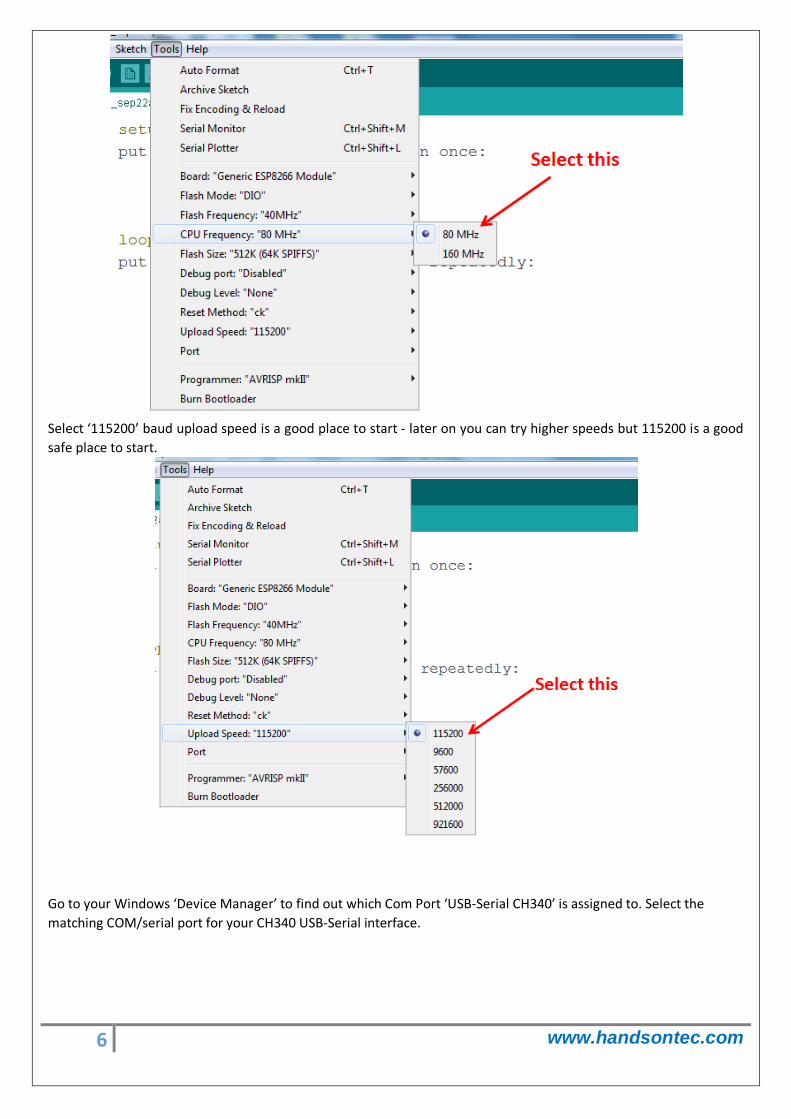
Select 80 MHz as the CPU frequency (you can try 160 MHz overclock later)
6 www.handsontec.com
Select ‘115200’ baud upload speed is a good place to start - later on you can try higher speeds but 115200 is a good safe place to start.
Go to your Windows ‘Device Manager’ to find out which Com Port ‘USB-Serial CH340’ is assigned to. Select the matching COM/serial port for your CH340 USB-Serial interface.
7 www.handsontec.com
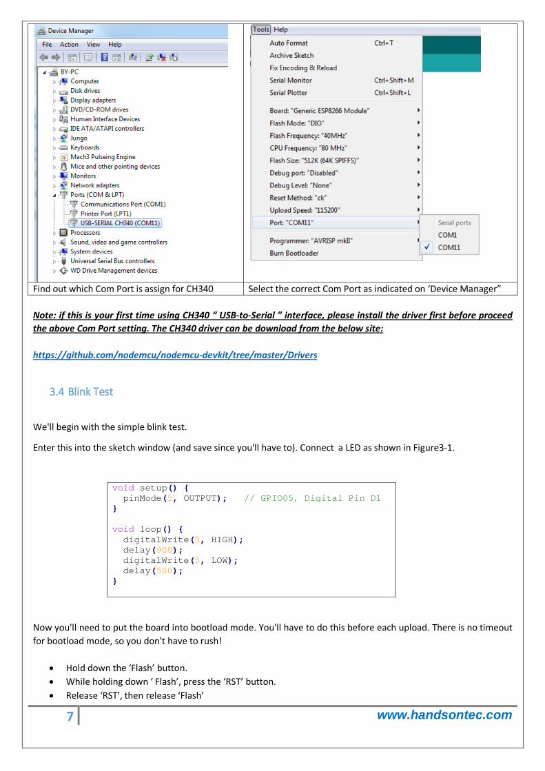
Find out which Com Port is assign for CH340 Select the correct Com Port as indicated on ‘Device Manager” Note: if this is your first time using CH340 “ USB-to-Serial ” interface, please install the driver first before proceed the above Com Port setting. The CH340 driver can be download from the below site:
3.4 Blink Test
https://github.com/nodemcu/nodemcu-devkit/tree/master/Drivers
We'll begin with the simple blink test.
Enter this into the sketch window (and save since you'll have to). Connect a LED as shown in Figure3-1.
void setup() { pinMode(5, OUTPUT); // GPIO05, Digital Pin D1 } void loop() { digitalWrite(5, HIGH); delay(900); digitalWrite(5, LOW); delay(500); }
Now you'll need to put the board into bootload mode. You'll have to do this before each upload. There is no timeout for bootload mode, so you don't have to rush!
• Hold down the ‘Flash’ button. • While holding down ‘ Flash’, press the ‘RST’ button. • Release ‘RST’, then release ‘Flash’
8 www.handsontec.com
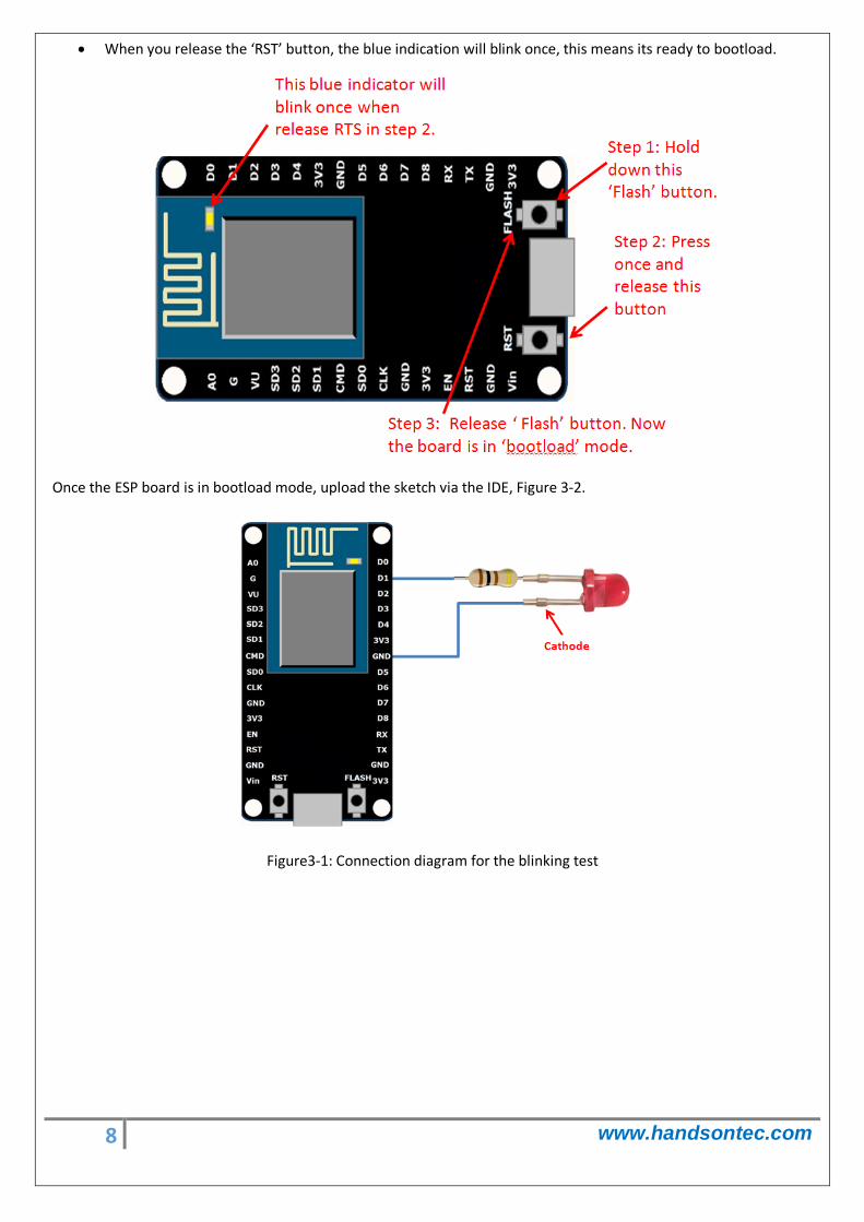
• When you release the ‘RST’ button, the blue indication will blink once, this means its ready to bootload.
Once the ESP board is in bootload mode, upload the sketch via the IDE, Figure 3-2.
Figure3-1: Connection diagram for the blinking test
9 www.handsontec.com
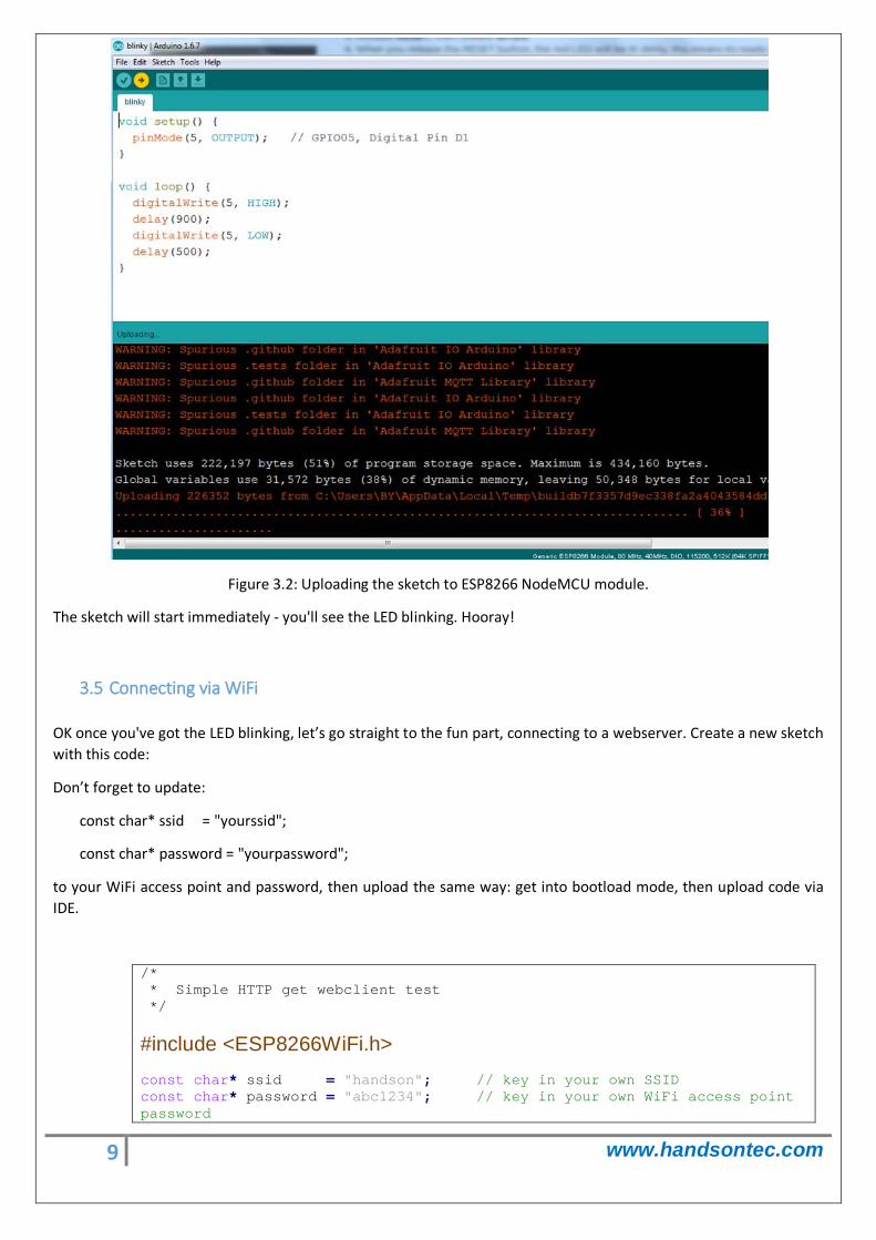
Figure 3.2: Uploading the sketch to ESP8266 NodeMCU module.
The sketch will start immediately - you'll see the LED blinking. Hooray!
3.5 Connecting via WiFi
OK once you've got the LED blinking, let’s go straight to the fun part, connecting to a webserver. Create a new sketch with this code:
Don’t forget to update:
const char* ssid = "yourssid";
const char* password = "yourpassword";
to your WiFi access point and password, then upload the same way: get into bootload mode, then upload code via IDE.
/* * Simple HTTP get webclient test */
#include <ESP8266WiFi.h> const char* ssid = "handson"; // key in your own SSID const char* password = "abc1234"; // key in your own WiFi access point password
10 www.handsontec.com
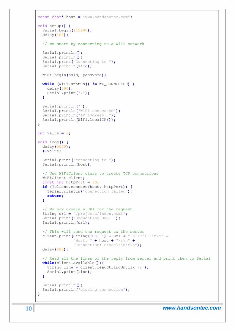
const char* host = "www.handsontec.com"; void setup() { Serial.begin(115200); delay(100); // We start by connecting to a WiFi network Serial.println(); Serial.println(); Serial.print("Connecting to "); Serial.println(ssid); WiFi.begin(ssid, password); while (WiFi.status() != WL_CONNECTED) { delay(500); Serial.print("."); } Serial.println(""); Serial.println("WiFi connected"); Serial.println("IP address: "); Serial.println(WiFi.localIP()); } int value = 0; void loop() { delay(5000); ++value; Serial.print("connecting to "); Serial.println(host); // Use WiFiClient class to create TCP connections WiFiClient client; const int httpPort = 80; if (!client.connect(host, httpPort)) { Serial.println("connection failed"); return; } // We now create a URI for the request String url = "/projects/index.html"; Serial.print("Requesting URL: "); Serial.println(url); // This will send the request to the server client.print(String("GET ") + url + " HTTP/1.1\r\n" + "Host: " + host + "\r\n" + "Connection: close\r\n\r\n"); delay(500); // Read all the lines of the reply from server and print them to Serial while(client.available()){ String line = client.readStringUntil('\r'); Serial.print(line); } Serial.println(); Serial.println("closing connection"); }
11 www.handsontec.com
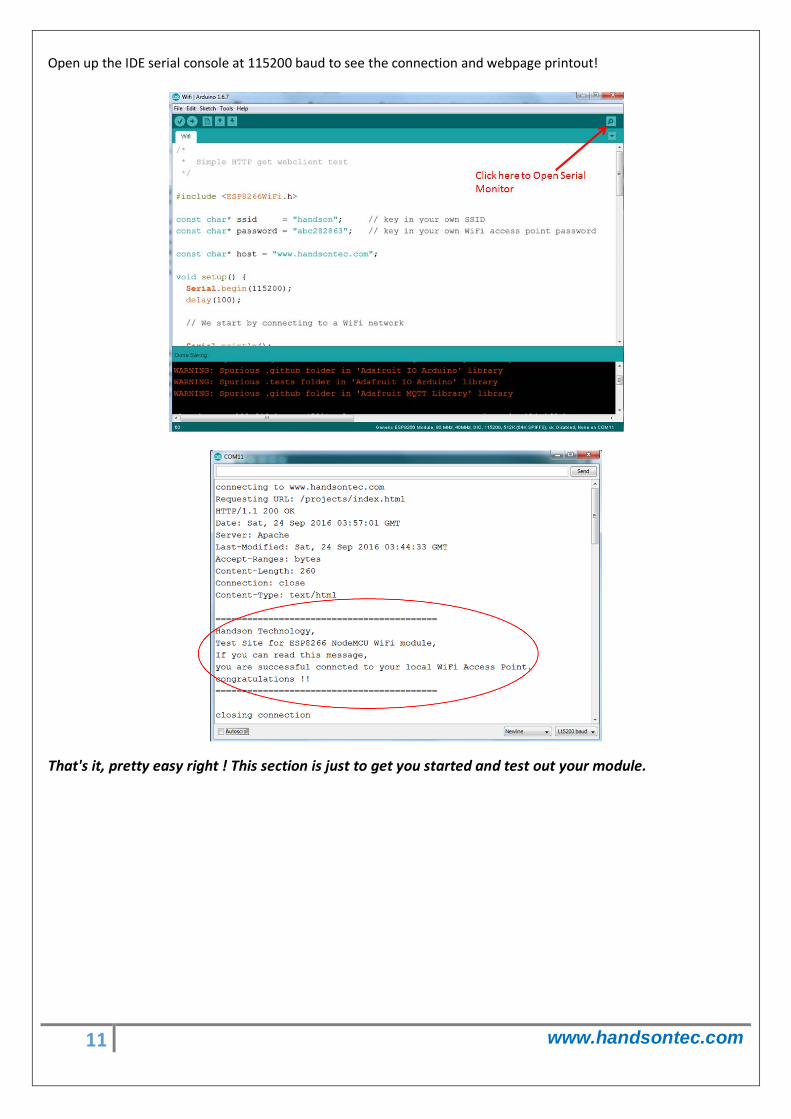
Open up the IDE serial console at 115200 baud to see the connection and webpage printout!
That's it, pretty easy right ! This section is just to get you started and test out your module.
12 www.handsontec.com
4. Flashing NodeMCU Firmware on the ESP8266 using Windows
Why flashing your ESP8266 module with NodeMCU?
NodeMCU is a firmware that allows you to program the ESP8266 modules with LUA script. And you’ll find it very similar to the way you program your Arduino. With just a few lines of code you can establish a WiFi connection, control the ESP8266 GPIOs, turning your ESP8266 into a web server and a lot more.
In this tutorial we are going to use another ESP8266 module with pin header adapter board which is breadboard friendly.
ESP8266 Module Breadboard Friendly with Header Connector
4.1 Parts Required:
• ESP8266 Module Breadboard Friendly • PL2303HX USB-UART Converter Cable • Some Male-to-Female Jumper Wires
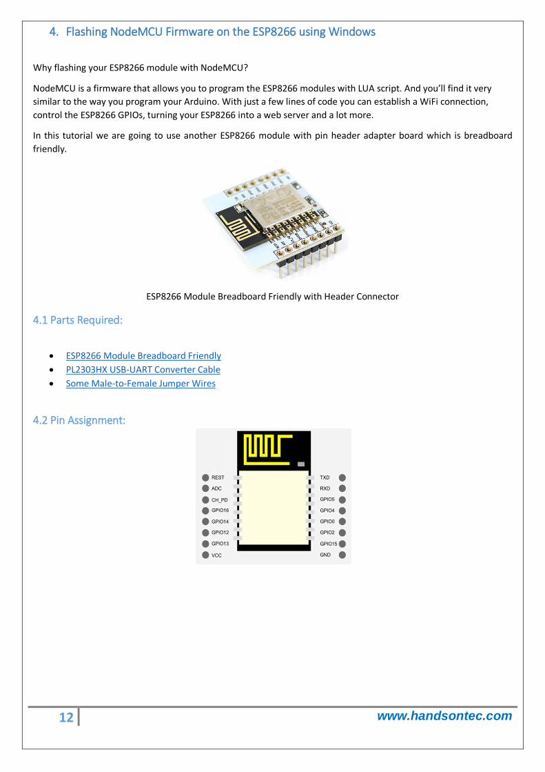
4.2 Pin Assignment:
13 www.handsontec.com
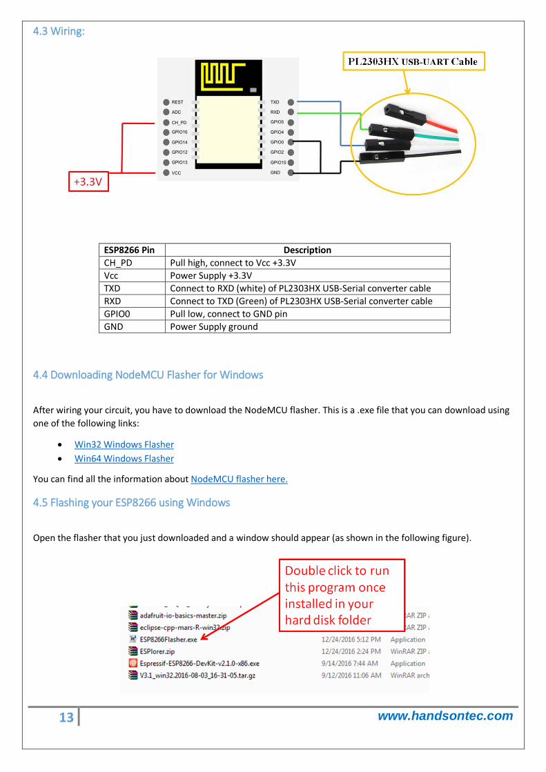
4.3 Wiring:
ESP8266 Pin Description CH_PD Pull high, connect to Vcc +3.3V Vcc Power Supply +3.3V TXD Connect to RXD (white) of PL2303HX USB-Serial converter cable RXD Connect to TXD (Green) of PL2303HX USB-Serial converter cable GPIO0 Pull low, connect to GND pin GND Power Supply ground
4.4 Downloading NodeMCU Flasher for Windows
After wiring your circuit, you have to download the NodeMCU flasher. This is a .exe file that you can download using one of the following links:
• Win32 Windows Flasher • Win64 Windows Flasher
You can find all the information about NodeMCU flasher here.
4.5 Flashing your ESP8266 using Windows
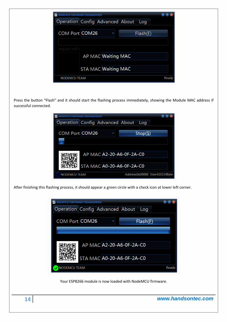
Open the flasher that you just downloaded and a window should appear (as shown in the following figure).
14 www.handsontec.com
Press the button “Flash” and it should start the flashing process immediately, showing the Module MAC address if successful connected.
After finishing this flashing process, it should appear a green circle with a check icon at lower left corner.
Your ESP8266 module is now loaded with NodeMCU firmware.
15 www.handsontec.com
5. Getting Started with the ESPlorer IDE
ESPlorer is an IDE (Integrated Development Environment) for ESP8266 devices. It’s a multi platform IDE, can be used in any OS environment, this simply means that it runs on Windows, Mac OS X or Linux.
Supported platforms:
• Windows(x86, x86-64) • Linux(x86, x86-64, ARM soft & hard float) • Solaris(x86, x86-64) • Mac OS X(x86, x86-64, PPC, PPC64)
This software allows you to establish a serial communications with your ESP8266 module, send commands, and upload code and much more.
Requirements:
• You need to have JAVA installed in your computer. If you don’t have, go to this website: http://java.com/download, download and install the latest version. It requires JAVA (SE version 7 and above) installed.
• In order to complete the sample project presented in this Guide you need to flash your ESP8266 with NodeMCU firmware. Refer to chapter-4 in this guide on how to flash the NodeMCU firmware.
Main Resources:
• ESPlorer Homepage: http://esp8266.ru/esplorer/ • GitHub Repository: https://github.com/4refr0nt/ESPlorer
5.1 Installing ESPlorer
Now let’s download the ESPlorer IDE, visit the following URL: http://esp8266.ru/esplorer/#download
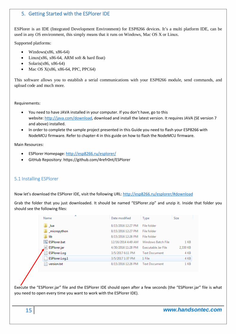
Grab the folder that you just downloaded. It should be named “ESPlorer.zip” and unzip it. Inside that folder you should see the following files:
Execute the “ESPlorer.jar” file and the ESPlorer IDE should open after a few seconds (the “ESPlorer.jar” file is what you need to open every time you want to work with the ESPlorer IDE).
16 www.handsontec.com
Note: If you’re on Mac OS X or Linux you simply use this command line in your terminal to run the ESPlorer: sudo java –jar ESPlorer.jar.
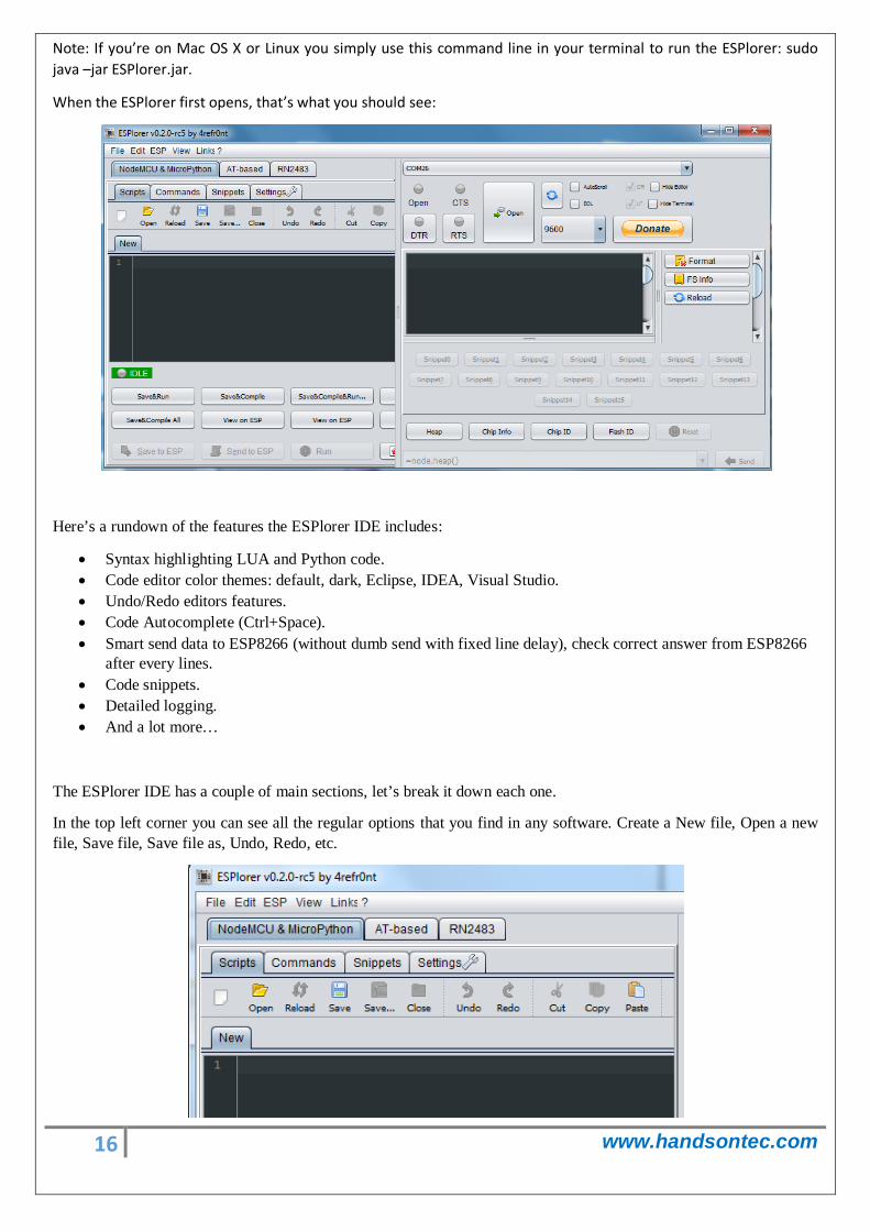
When the ESPlorer first opens, that’s what you should see:
Here’s a rundown of the features the ESPlorer IDE includes:
• Syntax highlighting LUA and Python code. • Code editor color themes: default, dark, Eclipse, IDEA, Visual Studio. • Undo/Redo editors features. • Code Autocomplete (Ctrl+Space). • Smart send data to ESP8266 (without dumb send with fixed line delay), check correct answer from ESP8266
after every lines. • Code snippets. • Detailed logging. • And a lot more…
The ESPlorer IDE has a couple of main sections, let’s break it down each one.
In the top left corner you can see all the regular options that you find in any software. Create a New file, Open a new file, Save file, Save file as, Undo, Redo, etc.
17 www.handsontec.com
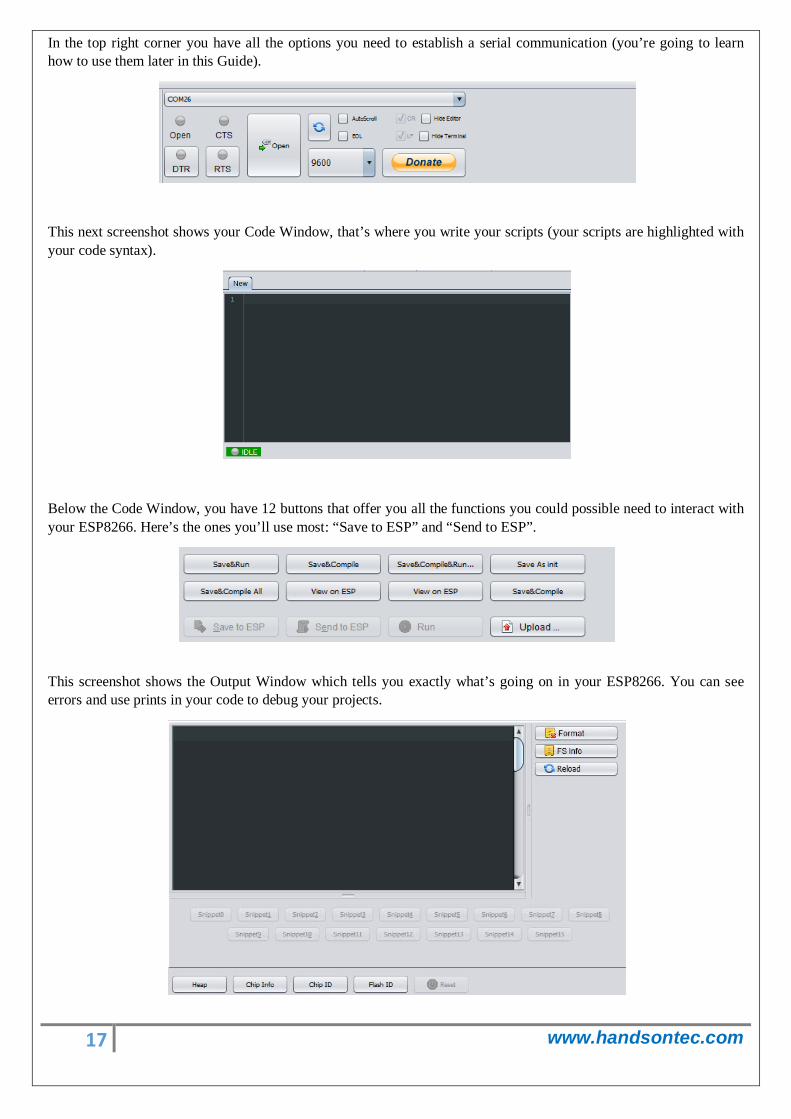
In the top right corner you have all the options you need to establish a serial communication (you’re going to learn how to use them later in this Guide).
This next screenshot shows your Code Window, that’s where you write your scripts (your scripts are highlighted with your code syntax).
Below the Code Window, you have 12 buttons that offer you all the functions you could possible need to interact with your ESP8266. Here’s the ones you’ll use most: “Save to ESP” and “Send to ESP”.
This screenshot shows the Output Window which tells you exactly what’s going on in your ESP8266. You can see errors and use prints in your code to debug your projects.
18 www.handsontec.com
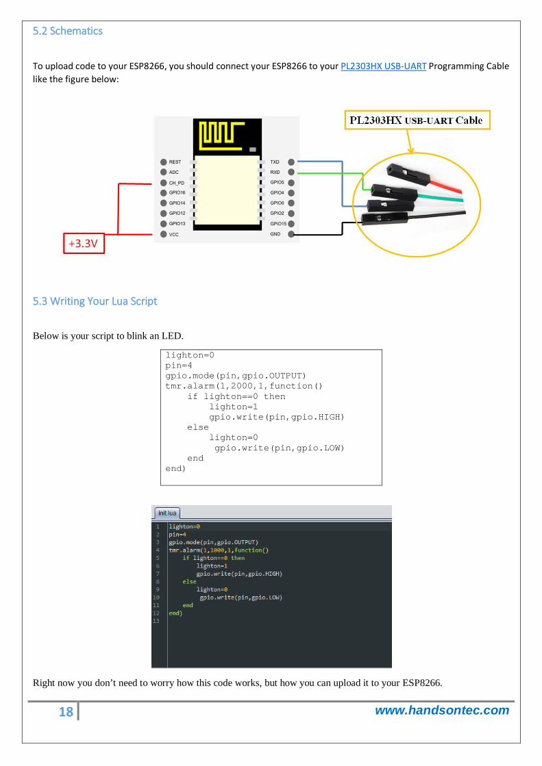
5.2 Schematics
To upload code to your ESP8266, you should connect your ESP8266 to your PL2303HX USB-UART Programming Cable like the figure below:
5.3 Writing Your Lua Script
Below is your script to blink an LED.
lighton=0 pin=4 gpio.mode(pin,gpio.OUTPUT) tmr.alarm(1,2000,1,function() if lighton==0 then lighton=1 gpio.write(pin,gpio.HIGH) else lighton=0 gpio.write(pin,gpio.LOW) end end)
Right now you don’t need to worry how this code works, but how you can upload it to your ESP8266.
19 www.handsontec.com
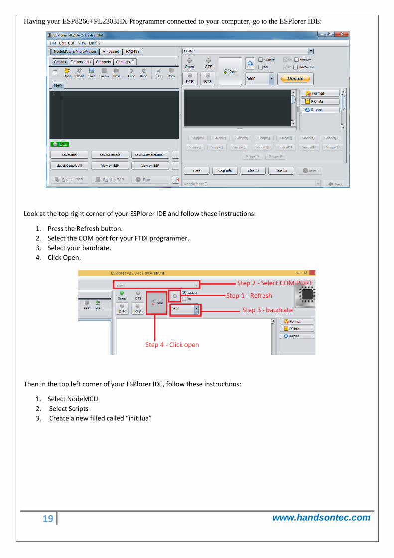
Having your ESP8266+PL2303HX Programmer connected to your computer, go to the ESPlorer IDE:
Look at the top right corner of your ESPlorer IDE and follow these instructions:
1. Press the Refresh button. 2. Select the COM port for your FTDI programmer. 3. Select your baudrate. 4. Click Open.
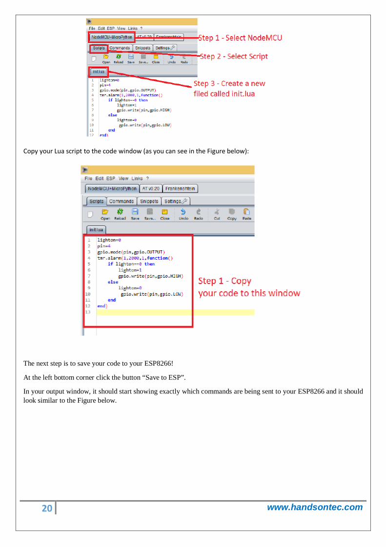
Then in the top left corner of your ESPlorer IDE, follow these instructions:
1. Select NodeMCU 2. Select Scripts 3. Create a new filled called “init.lua”
20 www.handsontec.com
Copy your Lua script to the code window (as you can see in the Figure below):
The next step is to save your code to your ESP8266!
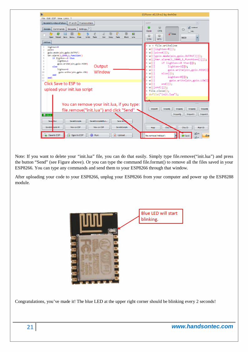
At the left bottom corner click the button “Save to ESP”.
In your output window, it should start showing exactly which commands are being sent to your ESP8266 and it should look similar to the Figure below.
21 www.handsontec.com
Note: If you want to delete your “init.lua” file, you can do that easily. Simply type file.remove(“init.lua”) and press the button “Send” (see Figure above). Or you can type the command file.format() to remove all the files saved in your ESP8266. You can type any commands and send them to your ESP8266 through that window.
After uploading your code to your ESP8266, unplug your ESP8266 from your computer and power up the ESP8288 module.
Congratulations, you’ve made it! The blue LED at the upper right corner should be blinking every 2 seconds!
22 www.handsontec.com
6. NodeMCU GPIO for Lua
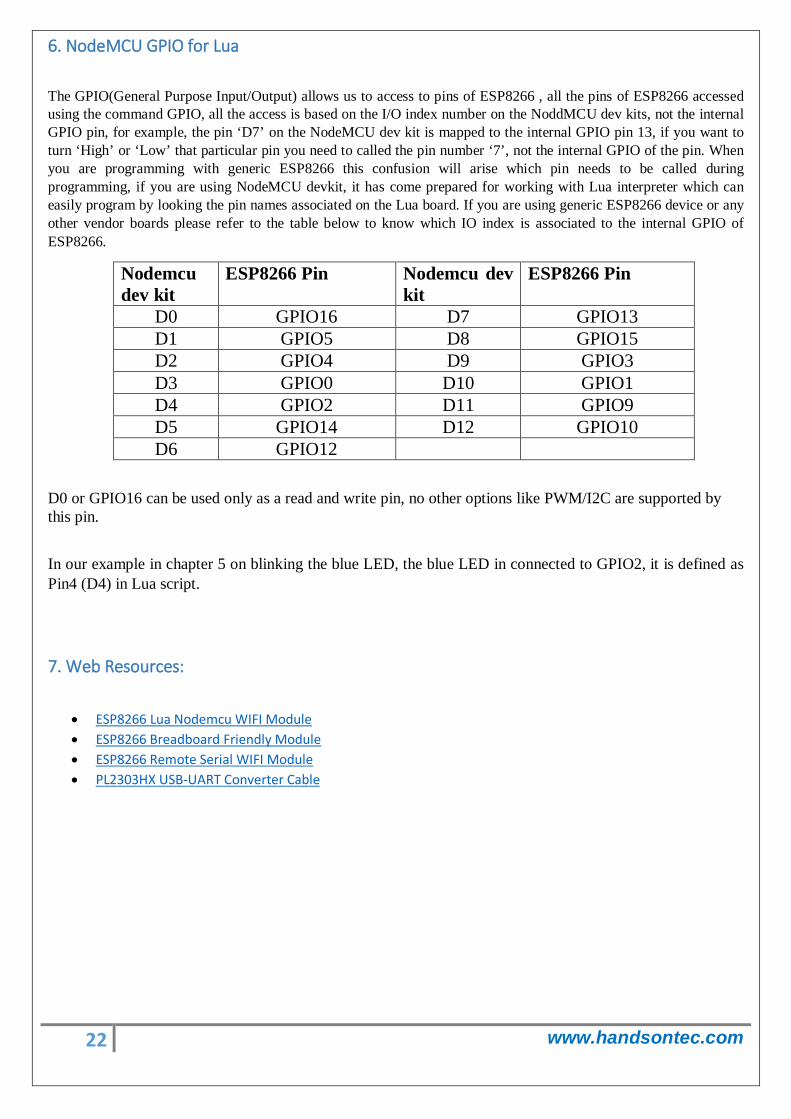
The GPIO(General Purpose Input/Output) allows us to access to pins of ESP8266 , all the pins of ESP8266 accessed using the command GPIO, all the access is based on the I/O index number on the NoddMCU dev kits, not the internal GPIO pin, for example, the pin ‘D7’ on the NodeMCU dev kit is mapped to the internal GPIO pin 13, if you want to turn ‘High’ or ‘Low’ that particular pin you need to called the pin number ‘7’, not the internal GPIO of the pin. When you are programming with generic ESP8266 this confusion will arise which pin needs to be called during programming, if you are using NodeMCU devkit, it has come prepared for working with Lua interpreter which can easily program by looking the pin names associated on the Lua board. If you are using generic ESP8266 device or any other vendor boards please refer to the table below to know which IO index is associated to the internal GPIO of ESP8266.
Nodemcu dev kit
ESP8266 Pin Nodemcu dev kit
ESP8266 Pin
D0 GPIO16 D7 GPIO13 D1 GPIO5 D8 GPIO15 D2 GPIO4 D9 GPIO3 D3 GPIO0 D10 GPIO1 D4 GPIO2 D11 GPIO9 D5 GPIO14 D12 GPIO10 D6 GPIO12
D0 or GPIO16 can be used only as a read and write pin, no other options like PWM/I2C are supported by this pin.
In our example in chapter 5 on blinking the blue LED, the blue LED in connected to GPIO2, it is defined as Pin4 (D4) in Lua script.
7. Web Resources:
• ESP8266 Lua Nodemcu WIFI Module • ESP8266 Breadboard Friendly Module • ESP8266 Remote Serial WIFI Module • PL2303HX USB-UART Converter Cable