Embed Size (px)
DESCRIPTION
eurocode 2, concrete, examples, EN 1992-1
Citation preview
Final Research Report: BD 2403
Companion DocumentEN 1992-1-1: Eurocode 2: Design of ConcreteStructures – Part 1: General rules and rulesfor buildings
Companion DocumentEN 1992-1-1: Eurocode 2: Design of ConcreteStructures – Part 1: General rules and rulesfor buildings
August 2007Department for Communities and Local Government: London
Final Research Report: BD 2403

The support of The Concrete Centre in finalising this report is acknowledged.
Whilst this document provides practical guidance on the use of Eurocode BS EN 1992-1-1 and
BS EN 1992-1-2 for the design of buildings, it shall only be applied in conjunction with both the
Eurocode and its National Annex published by the British Standards Institution.
It should be noted that this guidance has been based on the published Eurocode,
BS EN 1992-1-1:2004 and EN 1992-1-2: 2004 together with the draft of the respective National
Annexes, as available at the time of writing (January 2005).
Department for Communities and Local Government
Eland House
Bressenden Place
London
SW1E 5DU
Telephone: 020 7944 4400
Website: www.communities.gov.uk
© Crown Copyright, 2007
Copyright in the typographical arrangement rests with the Crown.
This publication, excluding logos, may be reproduced free of charge in any format or mediumfor research, private study or for internal circulation within an organisation. This is subject toit being reproduced accurately and not used in a misleading context. The material must beacknowledged as Crown copyright and the title of the publication specified.
Any other use of the contents of this publication would require a copyright licence. Please apply
for a Click-Use Licence for core material at www.opsi.gov.uk/click-use/system/online/pLogin.asp,
or by writing to the Office of Public Sector Information, Information Policy Team, St Clements
House, 2-16 Colegate, Norwich, NR3 1BQ. Fax: 01603 723000 or email:
If you require this publication in an alternative format please email
Communities and Local Government Publications
PO Box 236
Wetherby
West Yorkshire
LS23 7NB
Tel: 08701 226 236
Fax: 08701 226 237
Textphone: 08701 207 405
Email: [email protected]
or online via the Communities and Local Government website: www.communities.gov.uk
August 2007
Product Code: 07 BD 04723 (h)
CONTENTS
FOREWORD, SCOPE AND OBJECTIVES OF THE COMPANION GUIDE 50.1 Current status of Eurocodes 5
0.2 Scope and objectives of Companion Document to EN1992-1-1: Eurocode 2: 5
Design of Concrete Structures – Part 1: General rules and rules for buildings
0.3 Features of EN 1992–1–1 6
0.4 The Eurocodes, background, objectives and their status 6
0.5 Relationship between the Eurocodes and National Regulations/ 7
Public Authority Requirements
CHAPTER 1 8Introduction
1.1 The Eurocode System 8
1.2 Differences in philosophy between existing British Standards and Eurocodes 9
1.3 Supporting and related documents (product standards etc): 10
Required and available
1.4 Eurocode terminology and symbols 11
1.5 The use of EN1992-1-1 for structural concrete design 11
1.6 Role of National Annex – Using EN Eurocode at a National level 12
CHAPTER 2 15Basis of Structural Design
2.1 The use of EN1990 for structural concrete design 15
2.2 Resistance partial factors 21
CHAPTER 3 22Materials
3.1 Concrete – Comparison between EN 1992-1-1 and BS 8110 22
3.2 Reinforcement and prestressing steel – Comparisons between 23
EN 1992-1-1 and BS 8110
3.3 Ductility requirements 24
CHAPTER 4 25Durability and cover to reinforcement
4.1 Comparison between EN 1992-1-1 and BS 8110 25
4.2 Determination of required cover and link to design working life 25
and exposure class
CHAPTER 5 26Structural analysis
5.1 Load cases and combinations 26
5.2 Geometric Imperfections 27
5.3 Idealisation of structures 28
5.4 Redistribution 28
5.5 Slenderness and effective length of isolated members 28
5.6 Biaxial bending 29
CHAPTER 6 31Ultimate limit states
6.1 Design of flexural elements at the ultimate limit state 31
6.2 Shear 32
6.3 Torsion 36
6.4 Design of compression elements at the ultimate limit state 36
6.5 Flat slabs and design for punching shear 37
6.6 Material Partial Safety factors 39
6.7 Comparative design study 39
CHAPTER 7 42Serviceability limit states
7.1 Serviceability design and checks 42
7.2 Span/depth ratios 42
7.3 Partial factors for material properties for serviceability limit state 43
verifications
CHAPTER 8 44Additional guidance in EN 1992-1-1 (Sections 8–12 and Annexes)
8.1 Section 8 Detailing of reinforcement – general and Section 9 44
Detailing of members and particular rules
8.2 Section 10 Precast concrete elements and structures 45
8.3 Section 11 Lightweight aggregate concrete structures 45
8.4 Section 12 Plain and lightly reinforced concrete structures 45
8.5 Materials and Workmanship 45
8.6 Annexes to EN 1992-1-1 46
CHAPTER 9 47Conclusions
9.1 Availability of Guidance for EN 1992-1-1 47
9.2 Impact on the profession 48
9.3 Concluding remarks 48
REFERENCES 51
FOREWORD, SCOPE AND OBJECTIVESOF THE COMPANION GUIDE
0.1 Current status of EurocodesThe complete suite of the CEN Structural Eurocodes will be converted to full EN(European Standard) by 2005. This will include the package of codes relating tothe design of buildings in concrete. Following a period of co-existence betweenthe Eurocodes and the present National Codes, the National Codes will cease tobe maintained; this period is expected to be about 5 years after conversion. TheEuropean Commission, in close co-operation with representatives of MemberStates has prepared a document “Application and Use of the Eurocodes” [1],and Recommendations for the use of the Eurocodes [2].
0.2 Scope and objectives of CompanionDocument to EN1992-1-1: Eurocode 2: Designof Concrete Structures – Part 1: General rulesand rules for buildingsThis companion guide is intended to be a “high level” document, whose targetaudience are principally senior members of the profession. The document islikely to have a limited life and serve as an aid to introduce EN1992-1-1 [3]during the period of co-existence (see 0.1). This guide should not be useddirectly for design purposes. It follows the format of EN1992-1, with Chapters 1to 7 covering Sections 1 to 7 of EN 1992-1-1 and with Chapter 8 coveringSections 9 to 12. The Companion Document seeks to identify and discusswhere appropriate
• The main differences between EN 1992-1-1 and BS 8110
• Philosophical similarities between EN 1992-1-1 and BS 8110
• Changes in design principles
• Process change/design impact
• Information on handbooks, worked examples and other guidance on EN1992-1-1.
• Application within the UK together with the BSI National Annex.
5
For an explanation of the symbols used in this companion document, the readershould refer to EN 1991-1-1 or BS 8100 as appropriate
The editorial style of EN 1992-1-1 (see 0.3.2) is different from UK practice.BS 8110 gives direct guidance for the design of different member types, whereasEC2 concentrates on design principles. In this context the additional guidanceproduced by different organisations should prove invaluable to the UKprofession; in particular the EN 1992-1-1 “How to design leaflets” (see 9.1.2(2)),explaining the basic design concepts for structural elements.
0.3 Features of EN 1992–1–1EN 1992-1-1 gives general rules for all structures and comprehensive rules forthe design of buildings in plain, reinforced and prestressed concrete. Bothnormal weight and lightweight concrete are included.
The Sections in EN 1992-1-1 explain the basis of different phenomena (e.g.bending, shear, bond) rather than member types (e.g. beams, slabs, columns).
All Eurocodes use the limit state approach and the partial factor method ofverification.
0.4 The Eurocodes, background, objectives andtheir statusThe Commission of the European Community decided on an action programmein the field of construction based on article 95 of the Treaty of Rome. Within thisaction programme the Commission took the initiative to establish a set ofharmonised technical rules for the structural design of construction works, withthe following European Commission objective:
“The Eurocodes to establish a set of common technical rules for the design ofbuildings and civil engineering works which will ultimately replace thediffering rules in the various Member States”.
The Commission established in the mid 1970’s, a Steering Committeecontaining representatives of Member States, whose work on the Eurocodesprogramme, led to the publication of a set of first generation Eurocodes afterfifteen years.
In 1989 a Special Agreement was made between CEN and the EuropeanCommission bringing the responsibility of producing the structural Eurocodesto CEN. The agreement also specified that the Eurocodes are to serve asreference documents to be recognised by authorities of the Member States forthe following purposes:
a) as a means of compliance of building and civil engineering works with theEssential Requirements as set out in Council Directive 89/106/EEC (TheConstruction Products Directive), particularly Essential Requirement No 1 –
Companion Document to EN 1992-1-1
6

Mechanical resistance and stability and Essential Requirement No 2 –Safety in case of fire. The use of EN Eurocodes in technical specificationsfor products is described in the Commissions Guidance paper, ‘Applicationand Use of Eurocodes’. [1]
b) as a basis for specifying contracts for the execution of construction worksand related engineering services in the area of public works. This relates toCouncil Procurement Directives for:
• Works, which covers procurement by public authorities of civilengineering and building works, with a current (2004) threshold ofabout 5m Euros for an individual project, and
• Services, which covers procurement of services by public authorities,with current (2004) thresholds for Government Departments of 130kEuros and others, including local authorities of 200k Euros.
c) as a framework for drawing up harmonised technical specifications forconstruction products
0.5 Relationship between the Eurocodes andNational Regulations/Public AuthorityRequirementsThere is a clear and vital distinction between design codes and NationalRegulations/Public Authority Requirements. Harmonisation of Nationalrequirements is outside the scope of Eurocode development. It is the objectivehowever that the Eurocodes, together with their appropriate National Annexes,should be recognised in National Regulations as one of the routes for meetingcompliance. The legal status of the Eurocodes under the Building Regulationswill be exactly the same as that of the current National Codes of Practice. Inaccordance with normal rules following the introduction of EuropeanStandards, Eurocodes will be called up in public procurement specifications,and to be used for the design of products for the purpose of obtaining a CE(Conformité Européen) mark. See 0.4.
Foreword, scope and objectives of the Companion Guide
7
CHAPTER 1
Introduction
1.1 The Eurocode System
1.1.1 EUROCODE PROGRAMME AND THE RELATIONSHIP BETWEEN VARIOUSEUROCODES
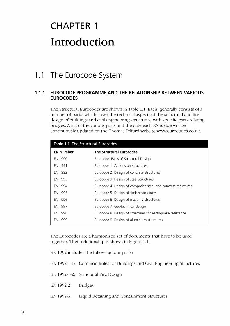
The Structural Eurocodes are shown in Table 1.1. Each, generally consists of anumber of parts, which cover the technical aspects of the structural and firedesign of buildings and civil engineering structures, with specific parts relatingbridges. A list of the various parts and the date each EN is due will becontinuously updated on the Thomas Telford website www.eurocodes.co.uk.
The Eurocodes are a harmonised set of documents that have to be usedtogether. Their relationship is shown in Figure 1.1.
EN 1992 includes the following four parts:
EN 1992-1-1: Common Rules for Buildings and Civil Engineering Structures
EN 1992-1-2: Structural Fire Design
EN 1992-2: Bridges
EN 1992-3: Liquid Retaining and Containment Structures
Table 1.1 The Structural Eurocodes
EN Number The Structural Eurocodes
EN 1990 Eurocode: Basis of Structural Design
EN 1991 Eurocode 1: Actions on structures
EN 1992 Eurocode 2: Design of concrete structures
EN 1993 Eurocode 3: Design of steel structures
EN 1994 Eurocode 4: Design of composite steel and concrete structures
EN 1995 Eurocode 5: Design of timber structures
EN 1996 Eurocode 6: Design of masonry structures
EN 1997 Eurocode 7: Geotechnical design
EN 1998 Eurocode 8: Design of structures for earthquake resistance
EN 1999 Eurocode 9: Design of aluminium structures
8
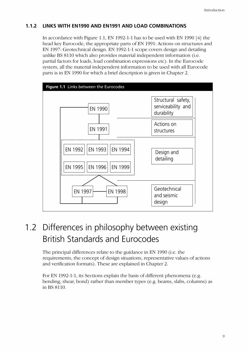
1.1.2 LINKS WITH EN1990 AND EN1991 AND LOAD COMBINATIONS
In accordance with Figure 1.1, EN 1992-1-1 has to be used with EN 1990 [4] thehead key Eurocode, the appropriate parts of EN 1991: Actions on structures andEN 1997: Geotechnical design. EN 1992-1-1 scope covers design and detailingunlike BS 8110 which also provides material independent information (i.e.partial factors for loads, load combination expressions etc). In the Eurocodesystem, all the material independent information to be used with all Eurocodeparts is in EN 1990 for which a brief description is given in Chapter 2.
1.2 Differences in philosophy between existingBritish Standards and EurocodesThe principal differences relate to the guidance in EN 1990 (i.e. therequirements, the concept of design situations, representative values of actionsand verification formats). These are explained in Chapter 2.
For EN 1992-1-1, its Sections explain the basis of different phenomena (e.g.bending, shear, bond) rather than member types (e.g. beams, slabs, columns) asin BS 8110.
Figure 1.1 Links between the Eurocodes
EN 1990EN 1990
EN 1991EN 1991
EN 1992EN 1992 EN 1993EN 1993 EN 1994EN 1994
EN 1995EN 1995 EN 1996EN 1996 EN 1999EN 1999
Structural Structural safetysafety,,serviceability serviceability andanddurabilitydurability
Actions onActions onstructuresstructures
Design andDesign anddetailingdetailing
EN 1997EN 1997 EN 1998EN 1998 GeotechnicalGeotechnicaland and seismicseismicdesigndesign
Introduction
9
1.3 Supporting and related documents (productstandards etc): Required and availableThe following standards are required for the use of EN 1992-1-1
1.3.1 GENERAL REFERENCE STANDARDS
EN 1990: Eurocode: Basis of structural design
EN 1991-1-5: Eurocode 1: Part 1-5: General actions: Thermal actions
EN 1991-1-6: Eurocode 1: Part 1-6: General actions: Actions during execution
1.3.2 OTHER REFERENCE STANDARDS
EN 1991: Eurocode 1: Actions on structures: all parts
EN 1997: Eurocode 7 Geotechnical design
EN 1998: Eurocode 8: Design of structures for earthquake resistance
EN 197-1: Cement: Composition, specification and conformity criteria forcommon cements
EN 206-1: Concrete: Specification, performance, production and conformity
EN 12390: testing hardened concrete
EN 10080: Steel for the reinforcement of concrete
EN 10138: Prestressing steels
EN ISO 17760: Permitted welding process for reinforcement
ENV 13670: Execution of concrete structures
EN 13791: Testing concrete
EN ISO 15630: Steel for the reinforcement and prestressing of concrete: Testmethods
hENs: Construction products relevant for concrete structures
Companion Document to EN 1992-1-1
10
1.4 Eurocode terminology and symbols
1.4.1 TERMINOLOGY
Most of the definitions given in the Eurocodes derive from ISO 2394R, ISO3898R, and ISO 8930R. In addition reference should be made to EN 1990 whichprovides a basic list of terms and definitions which are applicable to EN 1990 toEN 1999, thus ensuring a common basis for the Eurocode suite.
For the structural Eurocode suite, attention is drawn to the following keydefinitions, which may be different from current national practices:
• “Action” means a load, or an imposed deformation (e.g. temperature effectsor settlement)
• “Effects of Actions” or “Action effects” are internal moments and forces,bending moments, shear forces and deformations caused by actions
• “Strength” is a mechanical property of a material, in units of stress
• “Resistance” is a mechanical property of a cross-section of a member, or amember or structure.
1.4.2 SYMBOLS
The notation in the Eurocodes is based on ISO 3898R.
There are a few important changes from previous practice in the UK. Forexample, an x-x axis is along a member, a y-y axis is parallel to the flanges of asection, and z-z is the perpendicular to the flanges of a section.
Characteristic values of any parameter are distinguished by a subscript “k”.Design values have the subscript “d”.
1.5 The use of EN1992-1-1 for structural concretedesign
1.5.1 DISTINCTION BETWEEN PRINCIPLES AND APPLICATION RULES
The clauses in the EN 1991-1-2 are set out as either Principles or ApplicationRules. They are set out, as below, in EN 1990 and referred to by the otherEurocode parts.
• “Principles comprise general statements and definitions for which there isno alternative, as well as requirements and analytical models for whichno alternative is permitted unless specifically stated”
Introduction
11
• “The Principles are identified by the letter P following the paragraphnumber”. The word shall is always used in the Principle clauses
• “The Application Rules are generally recognised rules which comply withthe Principles and satisfy their requirements”
• “It is permissible to use alternative design rules different from theApplication Rules given in EN 1991-1-1 for works, provided that it is shownthat the alternative rules accord with the relevant Principles and are atleast equivalent with regard to the structural safety, serviceability anddurability which would be expected when using the Eurocodes”. (i.e. thesafety coefficient β as defined in EN 1990 [4] should be the same or greaterthan that of the application rule considered)
EN 1990 through a note to this point states
If an alternative design rule is substituted for an Application Rule, theresulting design cannot be claimed to be wholly in accordance with EN 1991-1-1 although the design will remain in accordance with the Principles of EN1991-1-1. When EN 1991-1-1 is used in respect of a property listed in an AnnexZ of a product standard or an ETAG, the use of an alternative design rule maynot be acceptable for CE marking.
With regard to the note to, the European Commission guidance paper L,Application and Use of the Eurocodes [1] states:
National Provisions should avoid replacing any EN Eurocode provisions, e.g.Application Rules, by national rules (codes, standards, regulatory provisions,etc).
When, however, National Provisions do provide that the designer may – evenafter the end of the co-existence period – deviate from or not apply the ENEurocodes or certain provisions thereof (e.g. Application Rules), then thedesign will not be called “a design according to EN Eurocodes”.
• “Application Rules are identified by a number in brackets” (only). The verbshould is normally used for application rules. The verb may is also used forexample as an alternative application rule. The verbs is and can are used fora definitive statement or as an assumption.
1.6 Role of National Annex – Using EN Eurocodeat a National levelIt is the responsibility of each national standards body (e.g. British StandardsInstitute (BSI) in the UK) to implement Eurocodes as national standards.
Companion Document to EN 1992-1-1
12

Keya: National Title Page; b: Foreword; c: EN Title page; d: EN Text; e: EN Annexes; f: National Annex
The national standard implementing each Eurocode part – will comprise,without any alterations, the full text of the Eurocode and its annexes aspublished by the CEN (Figure 1.2, boxes c, d and e). This may be preceded by anational title page (box a) and national foreword (box b), and may be followedby a national annex (box f). (See 1.6.1).
1.6.1 RULES AND CONTENTS OF NATIONAL ANNEXES FOR EUROCODES
The European Commission recognising the responsibility of regulatory andnational competent authorities in each EU Member State has safeguarded theirright to determine values related to safety matters at national level through anational annex. These safety matters include different levels of protection thatmay prevail at national, regional or local level, and ways of life.
A National Annex may only contain information on those parameters which areleft open in the Eurocode for national choice, known as Nationally DeterminedParameters, (see 1.6.2) to be used for the design of buildings and civilengineering works to be constructed in the country concerned. Where aEurocode Clause allows choice, a recommended value or method is given.
1.6.2 NATIONALLY DETERMINED PARAMETERS (NDPs)
NDPs will allow Member States to choose the level of safety, applicable to theirterritory. The values, classes or methods to be chosen or determined at nationallevel, are:
Figure 1.2 National Standards Implementing Eurocodes
a
bc
d
e
f
a
bc
d
e
f
Introduction
13
• Values and/or classes where alternatives are given in the Eurocode (e.g.levels of safety)
• Values to be used where only a symbol is given in the Eurocode (e.g. partialfactors)
• Country-specific data (geographical, climatic, etc) (e.g. snow maps)
• Procedures to be used where alternative procedures are given in theEurocodes.
1.6.3 NATIONAL ANNEXES
The National Standards Bodies (i.e. BSI in the UK) should publish the NDPs in aNational Annex. A National Annex is not required if a Eurocode part is notrelevant for the Member State (e.g. seismic design for some countries).
In addition to NDPs a National Annex may also contain:
• Decisions on the application of informative annexes
• References to non-contradictory complementary information (NCCI) toassist the user in applying the Eurocode.
It should be noted that in EN 1992-1-1, NDPs are used for other situations thanjust to safeguard Member States’ rights to define safety. They have been used tocover situations where there is no possibility of a consensus view being reachedon an issue (e.g. for most of the serviceability section and the sections ondetailing rules in EN 1992-1-1). It is hoped that in the first revision of EN 1992-1-1 many of these NDPs will be rationalised.
Companion Document to EN 1992-1-1
14
CHAPTER 2
Basis of Structural Design
2.1 The use of EN1990 for structural concretedesign
2.1.1 DIFFERENCES BETWEEN EN 1990: EUROCODE BASIS OF STRUCTURALDESIGN AND UK PRACTICE
This Chapter briefly describes the objectives of EN 1990, lists the requirementsand provides information on the representative values of the loads to be used inthe combination of actions for use with the design and detailing clauses of EN1992-1-1. It also gives the values adopted by the BSI national annex to EN 1990.
There are some differences between EN 1990 and UK practice (i.e. the materialindependent clauses from Chapter 2 of BS 8110 and Chapter 2 of BS 5950 etc).The principal differences that will be explained here are:
• The requirements of EN 1990 (see 2.1.3)
• The design situations to consider for both the ultimate and serviceabilitylimit states (see 2.1.3 c)
• The representative values of the actions to use for the different designsituations (see 2.1.5)
• The expressions for combining the effects of actions (see 2.1.6)
• The factors of safety to use for the appropriate design situations (see 2.1.6.3and 2.1.7.2)
• Choices made in the UK National Annex to EN 1990 (see 2.1.8).
Gulvanessian, Calgaro and Holicky provide a comprehensive description,background and commentary to EN 1990 [5]. Chapter 2 of the BRE Handbookon Actions on Structures also provides guidance on EN 1990 [6], whichdescribes the background to the selections made in the BSI National Annex toEN 1990.
15
2.1.2 OBJECTIVES AND FUNCTION AND REQUIREMENTS OF EN 1990
EN 1990 [4] is the head key Eurocode for the harmonised Structural Eurocodes.EN 1990 establishes and provides comprehensive information and guidance forall the Eurocodes, on the principles and requirements for safety, serviceability,describes the basis of their design and verification, and gives guidelines forrelated aspects of structural reliability and durability of structures. It is based onthe limit state concept and used in conjunction with the partial factor method.EN 1992 does not give the material-independent clauses required for design.These are only included in EN 1990. Hence very importantly EN 1990 has to beused with all the Eurocode parts and it provides the information for safetyfactors for actions and combination for action effects for the verification of bothultimate and serviceability limit states.
2.1.3 REQUIREMENTS
The requirements of EN 1990 which need to be adhered to by EC2 are
(i) Fundamental Requirements: These relate to safety, serviceability androbustness requirements
(ii) Reliability Differentiation
(iii) Design Situations: EN 1990 stipulates that a relevant design situation isselected taking account of the circumstances in which the structure may berequired to fulfil its function. EN 1990 classifies design situations forultimate limit state verification as follows:
• Persistent situations (conditions of normal use)
• Transient situations (temporary conditions e.g. during execution)
• Accidental situations and
• Seismic situations.
(iv)Design Working Life: For buildings and other common structures therecommended design working life (i.e. the assumed period for which astructure is to be used for its intended purpose with anticipatedmaintenance but without major repair being necessary) is 50 years. Forconcrete, design working life needs to be considered for material propertydeterioration, life cycle costing and evolving maintenance strategies.
(v) Durability
(vi)Quality Assurance
The above requirements are discussed comprehensively in [5] and [6]
Companion Document to EN 1992-1-1
16
2.1.4 PRINCIPLES OF LIMIT STATE DESIGN
2.1.4.1 Ultimate and Serviceability Limit States(a) Ultimate limit states are those associated with collapse or with other
forms of structural failure and concern:
• The safety of people in or about the structure and
• The safety of the structure and its contents.
(b) Serviceability limit states correspond to conditions beyond whichspecified service requirements for a structure or structural element are nolonger met and concern:
• The functioning of the construction works or parts of them
• The comfort of people in or about the structure and
• The appearance.
2.1.4.2 Limit State DesignLimit state design is carried out by:
• Setting up structural and load models for relevant ultimate and serviceabilitylimit states (i.e. the design situations, see 2.1.3(iii) and 2.1.4.1(b)) to beconsidered in the various design situations and load cases and
• Verifying that the criteria for a limit state is not exceeded when the designvalues for actions, material properties and geometrical data are used in themodels.
There are differences between the concept of design situations approach in EN1990 and approach of the BSI codes. In the verification of serviceability limitstates in EN 1990, separate load combination expressions are used dependingon the design situation being considered. For each of the particular designsituations an appropriate representative value for an action is used, (see 2.1.7).
2.1.5 THE REPRESENTATIVE VALUES OF THE ACTIONS TO USED FOR THEDIFFERENT DESIGN SITUATIONS
2.1.5.1 The representative values of the actionsIn addition to the characteristic values of actions which are similar to the BSIdefinition, other representative values are specified in EN 1990 for variable andaccidental actions. Three representative values commonly used for variableactions are the combination value ψ0Qk, the frequent value ψ1Qk and the quasi-permanent value ψ2Qk. The factors ψ0, ψ1 and ψ2 are reduction factors of thecharacteristic values of variable actions.
The combination value ψ0Qk, the frequent value ψ1Qk, and the quasi-permanentvalue ψ2Qk are explained below.
Basis of structural design
17
The combination value ψ0Qk is associated with the combination of actionsfor ultimate and irreversible serviceability limit states (the serviceability limitstates where some consequences of actions exceeding the specified servicerequirements will remain when the actions are removed) in order to takeaccount of the reduced probability of simultaneous occurrence of the mostunfavourable values of several independent actions.
The frequent value ψ1Qk is primarily associated with the frequentcombination in the serviceability limit states and it is also assumed to beappropriate for verification of the accidental design situation of the ultimatelimit states. In both cases the reduction factor ψ1 is applied as a multiplier of theleading variable action.
The main use of quasi-permanent values ψ2Qk is the assessment of long-term effects, for example in checking cracking or deflection. But they are alsoused for the representation of variable actions in accidental and seismiccombinations of actions (ultimate limit states) and for verification of frequentand quasi-permanent combinations (long term effects) of serviceability limitstates.
Values for all the three coefficients ψ0, ψ1 and ψ2 for buildings are given in theBSI National Annex A to EN 1990. [4]
2.1.6 VERIFICATION BY THE PARTIAL FACTOR METHOD
Note: The expression numbers given in the Chapter are those given in EN 1990.
2.1.6.1 Ultimate Limit StatesFor the ultimate limit state verification, EN 1990 stipulates that the effects ofdesign actions do not exceed the design resistance of the structure at theultimate limit state; and the following ultimate limit states need to be verified.
a) For the limit state verification for static equilibrium (EQU)
Ed ,dst ≤ Ed ,stb (6.7)
where :
Ed ,dst is the design value of the effect of destabilising actions;
Ed ,stb is the design value of the effect of stabilising actions.
b) For internal failure or excessive deformation of the structure or structuralmembers, including footings, piles, basement walls, etc., where the strengthof construction materials of the structure governs (STR); and for failure orexcessive deformation of the ground where the strengths of soil or rock aresignificant in providing resistance (GEO);
Ed ≤ Rd (6.8)
where :
Companion Document to EN 1992-1-1
18
Ed is the design value of the effect of actions such as internal force, momentor a vector representing several internal forces or moments;
Rd is the design value of the corresponding resistance.
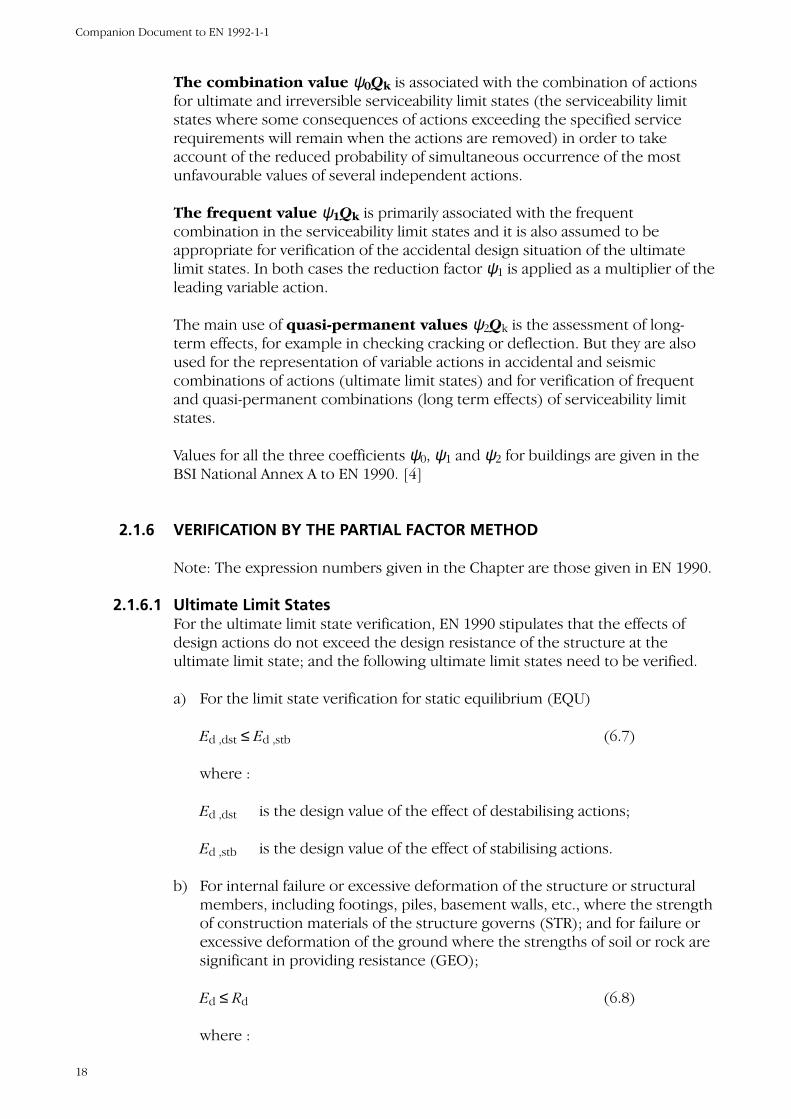
2.1.6.2 Combination of Actions for Ultimate Limit Statesa) The fundamental (persistent and transient) design situations for ultimate
limit state verifications, other than those relating to fatigue, are symbolicallyrepresented as follows:
(6.10)
This combination assumes that a number of variable actions are actingsimultaneously, Qk1 is the dominant variable action and this is combined withthe combination value of the accompanying variable actions Qki.
P is a relevant representative value for prestressing actions.
Alternatively EN 1990 allows the use of the following equations together.
(6.10a)
(6.10b)
where ξ is a reduction factor for γGj within the range 0.85 to 1.
In the case of (6.10a) and (6.10b) the National Annex may additionally modifyexpression 6.10a to include permanent actions only. (i.e. The variable actionsare not included in (6.10a)).
The more unfavourable of expressions (6.10a) and (6.10b) may be appliedinstead of expression 6.10, but only under conditions defined by the NationalAnnex.
EN 1990 also provides expressions for verifying both the accidental and seismicdesign situations.
2.1.6.3 Partial factors for the ultimate limit statesFor buildings, the recommended partial factors for the persistent and transientsituation in EN 1990 are γG =1.35 and γQ = 1.5, but these may be altered by theNational Annex. Values of combination coefficient ψ are given in EN 1990.
2.1.7 SERVICEABILITY LIMIT STATES
For the serviceability limit states verification EN 1990 stipulates that:
Ed ≤ Cd (6.13)
+++
+++
∑∑∑∑
>≥
>≥
1ii,ki,0i,Q1,k1,QP
1jj,kj,Gj
1ii,ki,0i,Q1,k1,01,QP
1jj,kj,G
""""""
""""""
QQPG
QQPG
ψγγγγξ
ψγψγγγ
ik,i0,iQ,k,1Q,1Pjk,,1>i1
"+""+""+" QQPGj
jG ψγγγγ ∑∑≥
Basis of structural design
19
where :
Cd is the limiting design value of the relevant serviceability criterion.
Ed is the design value of the effects of actions specified in the serviceabilitycriterion, determined on the basis of the relevant combination.
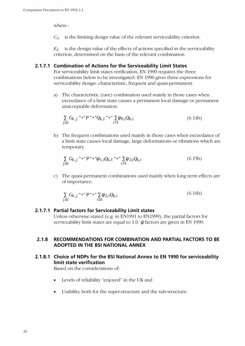
2.1.7.1 Combination of Actions for the Serviceability Limit StatesFor serviceability limit states verification, EN 1990 requires the threecombinations below to be investigated: EN 1990 gives three expressions forserviceability design: characteristic, frequent and quasi-permanent.
a) The characteristic (rare) combination used mainly in those cases whenexceedance of a limit state causes a permanent local damage or permanentunacceptable deformation.
(6.14b)
b) The frequent combinations used mainly in those cases when exceedance ofa limit state causes local damage, large deformations or vibrations which aretemporary.
(6.15b)
c) The quasi-permanent combinations used mainly when long term effects areof importance.
(6.16b)
2.1.7.1 Partial factors for Serviceability Limit statesUnless otherwise stated (e.g. in EN1991 to EN1999), the partial factors forserviceability limit states are equal to 1.0. ψ factors are given in EN 1990.
2.1.8 RECOMMENDATIONS FOR COMBINATION AND PARTIAL FACTORS TO BEADOPTED IN THE BSI NATIONAL ANNEX
2.1.8.1 Choice of NDPs for the BSI National Annex to EN 1990 for serviceabilitylimit state verificationBased on the considerations of:
• Levels of reliability “enjoyed” in the UK and
• Usability, both for the super-structure and the sub-structure.
∑∑≥≥ 1
ik,i2,1
, "+" "+" ij
jk QPG ψ
∑∑>≥ 1
ik,i2,k,11,11
, "+" "+" "+" ij
jk QQPG ψψ
∑∑>≥ 1
ik,i0,k,11
, "+" "+" "+" ij
jk QQPG ψ
Companion Document to EN 1992-1-1
20
The UK national Annex has adopted the use of either:
• Expression 6.10 with γG = 1,35 and γQ = 1,5, or
• Expression 6.10a and 6.10b with γG = 1,35 and γQ = 1,5 andξ = 0,925.
for the persistent and transient design situations with the EN 1990recommended Ψ values, except the ψ0 values for wind is reduced from 0,6 to0,5.
For the accidental design situations Expression (6.11b) of EN 1990 is adopted inthe BSI National Annex and ψ 1,1 is chosen for the loading variable action.
2.1.8.2 Choice of NDPs for the BSI National Annex to EN 1990 for serviceabilitylimit state verificationThe BSI National Annex adopts the expression (6.14b) and (6.15b) and (6.16b)with γ =1, and the ψ values as for the ultimate limit state verifications.
2.2 Resistance partial factorsThe material partial safety factors γc and γs are given in Chapter 6, Clause 6.6 forultimate limit state verifications and Chapter 7, Clause 7.3 for serviceability limitstate verifications.
Basis of structural design
21
CHAPTER 3
Materials
3.1 Concrete – Comparison between EN 1992-1-1and BS 8110
3.1.1 CYLINDER/CUBE STRENGTH
The cylinder strength of concrete is used in all expressions in EN 1992-1-1.
EN 1992-1-1 gives the relationship between cube and cylinder strengths.Throughout EN 1992-1-1, reference to concrete strength class uses both thecube and cylinder strengths (e.g. C 30/37, in which 30 is the cylinder strength inMPa (N/mm2) and 37 is the corresponding cube strength).
Note: The cylinder strength is approximately 80% of the cube strength.
3.1.2 STRENGTH CLASSES
EN 1992-1-1 provides guidance for design using certain high strength concretes,which BS8110 does not. The maximum characteristic cylinder strength fck
permitted is 90N/mm2, which corresponds to a characteristic cube strength of105N/mm2 (i.e. C90/105).
EN 1992-1-1 provides guidance values, which may be used in the absence ofbetter data, for the consideration of creep, shrinkage and elastic modulus.
3.1.3 NON-LINEAR CREEP
When the concrete compressive service stress at loading exceeds 0.45 fck, creepshould be considered as being non-linear. This will normally only come intoeffect where there are high levels of pre-stress.
3.1.4 DESIGN COMPRESSIVE AND TENSILE STRENGTHS
In determining the value of the design compressive strength EN 1992-1-1recommends a value for αcc equal to 1,0.
Note: EN 1992-1-1 defines αcc as follows.
22
“αcc coefficient taking account of long term effects on the compressivestrength and of unfavourable effects resulting from the way the load isapplied.”
Using a value of 1,0 in the UK will have an identical effect on design as changingthe partial safety factor, γc, from 1.5 to 1.275 for the design of sections forflexure or flexure combined with axial load.
In the absence of a clear justification for such a reduction in safety the BSINational Annex to EN 1992-1-1 has adopted a value for αcc equal to 0.85.
Note: The value of 0.85 was first explicitly given in the 1970 CEB/FIP“Recommendations for an international code of practice for reinforcedconcrete” Though the definitions of αcc have changed from document todocument, the value of 0.85 has remained unchanged and is included in theCEB 1990 Model Code.
3.1.5 STRESS BLOCK
The forms of stress block and comparisons between EN 1992-1-1 and BS 8110are given in Chapter 6.
3.1.6 PRODUCTION OF CONCRETE
The production of concrete should comply with the provisions of EN 206[7]and BS 8500 Part 2 [11].
3.1.7 DENSITIES FOR CONCRETE
In EN 1991-1-1 [9] a value of 25kN/m3 is given for the density of normal weightconcrete compared to the value of 23.6 kN/m3 given in BS 8110.
3.2 Reinforcement and prestressing steel –Comparisons between EN 1992-1-1 and BS8110
3.2.1 REINFORCING STEEL
The reinforcement specified when using EN 1992-1-1 generally needs to complywith EN 10080, and the Annex C (Normative ) of EN 1992-1-1 for the mechanicalproperties. Information is given only for ribbed reinforcement.
Note: The true characteristic strength of reinforcement currently used in the UKis 500 MPa and the partial factor of 1.15 should be applied to this strength.
Materials
23
3.3 Ductility requirementsEC2 specifies three levels of ductility for reinforcing steel. If class Areinforcement is used, the maximum amount of redistribution permitted is 20%otherwise the upper 30% limit applies. Class C reinforcement needs only bespecifically specified for seismic designs or in other situations requiring highductility such as in cold climates, though its use in other circumstances isacceptable.
3.3.1 PRESTRESSING STEEL
Prestressing steel should comply with EN 10138.
Companion Document to EN 1992-1-1
24
CHAPTER 4
Durability and cover to
reinforcement
4.1 Comparison between EN 1992-1-1 andBS 8110Comparisons between EN 1992-1-1 and BS 8110 made in this companiondocument have assumed that the required covers to be provided are essentiallyunaltered. Simplified guidance to enable engineers to determine the requiredcover to be provided in different circumstances is in course of preparation andwill be included within the BSI National Annex to EN 1992-1-1.
Cover for durability and bond requirements is specified as a minimum value inEN 1992-1-1 whereas BS8110 specifies cover as a nominal value.
Compared to BS 8110, durability considerations are considered in a moreexplicit manner in EN 1992-1-1. For example EN 1992-1-1 has classificationsbased around potential deterioration mechanisms. The concept of an explicitlydefined design life is included and the designer is required to identify the mostsevere environmental conditions for each particular case, rather than assessingthe environmental exposure as for BS 8110.
The concept of an explicitly defined design life and the recognition of the needto take additional measures if this design life is required to be significantlyexceeded must be seen as a positive step forward.
4.2 Determination of required cover and link todesign working life and exposure classEN 206 [7] defines six exposure classes and these are repeated in EN 1992-1-1.EN 1992-1-1 recommends concrete grades and cover to reinforcement fordesign working life of 50 and 100 years.
The BSI National Annex will provide its own values. Covers to be shown on thedrawings are nominal values, which are the sum of the minimum value requiredfor durability and the construction/production tolerance, ∆c,dev.
25
CHAPTER 5
Structural analysis
5.1 Load cases and combinations
5.1.1 COMPARISON BETWEEN EN 1992-1-1 AND BS 8110
a) Expressions for the combination of action effects, and values forpartial factorsChapter 2 describes the two basic approaches given in EN 1990 for combiningaction effects (e.g. expression (6.10), or expressions (6.10a) and (6.10b) actingtogether). Expression (6.10) is similar in concept to BS 8110 expressions.However when two variable actions are being considered there are largedifferences between EN 1990 and the BSI recommendations, as EN 1990 morelogically uses the representative value of the action (See 2.1.5).
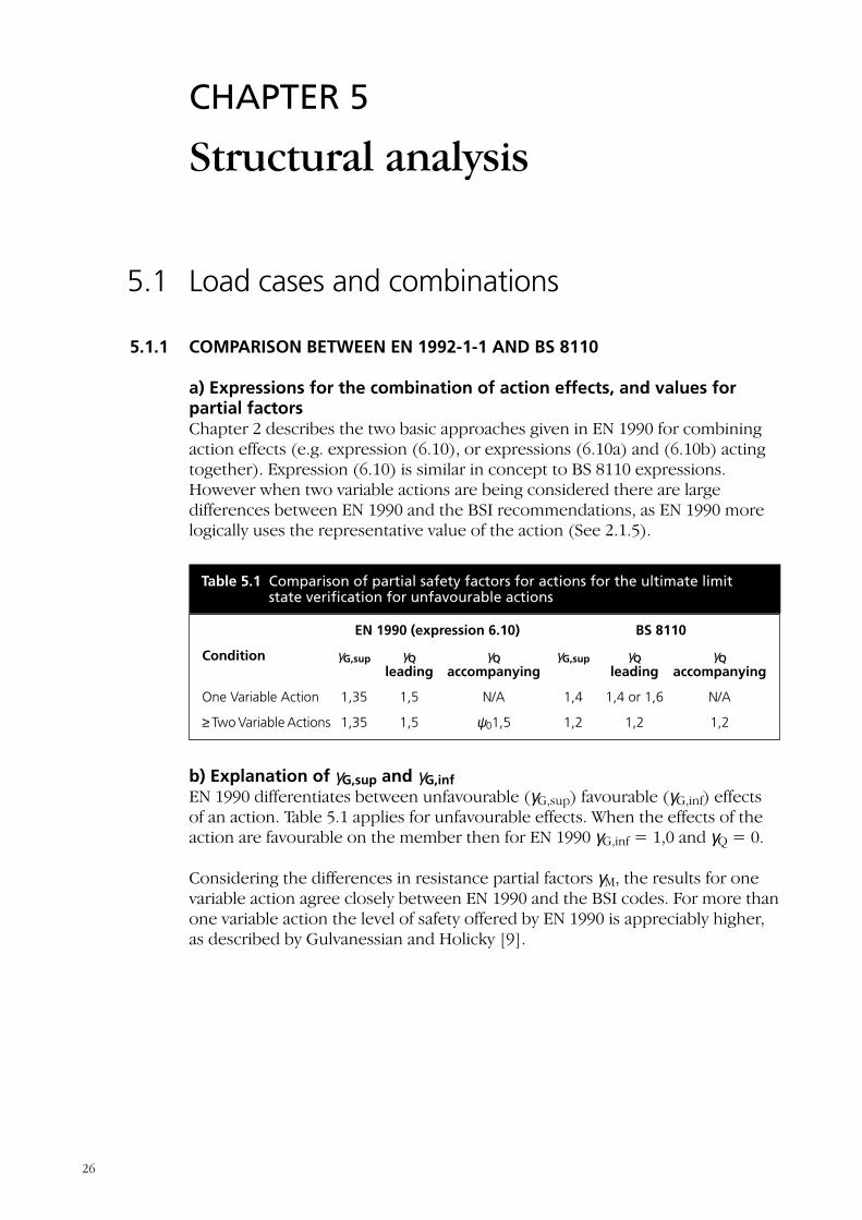
b) Explanation of γG,sup and γG,infEN 1990 differentiates between unfavourable (γG,sup) favourable (γG,inf) effectsof an action. Table 5.1 applies for unfavourable effects. When the effects of theaction are favourable on the member then for EN 1990 γG,inf = 1,0 and γQ = 0.
Considering the differences in resistance partial factors γM, the results for onevariable action agree closely between EN 1990 and the BSI codes. For more thanone variable action the level of safety offered by EN 1990 is appreciably higher,as described by Gulvanessian and Holicky [9].
Table 5.1 Comparison of partial safety factors for actions for the ultimate limitstate verification for unfavourable actions
EN 1990 (expression 6.10) BS 8110
Condition γG,sup γQ γQ γG,sup γQ γQ leading accompanying leading accompanying
One Variable Action 1,35 1,5 N/A 1,4 1,4 or 1,6 N/A
≥ Two Variable Actions 1,35 1,5 ψ01,5 1,2 1,2 1,2
26
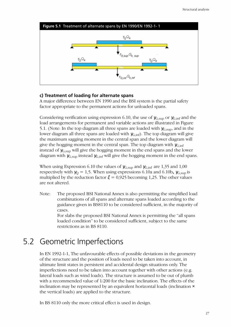
c) Treatment of loading for alternate spansA major difference between EN 1990 and the BSI system is the partial safetyfactor appropriate to the permanent actions for unloaded spans.
Considering verification using expression 6.10, the use of γG,sup or γG,inf and theload arrangements for permanent and variable actions are illustrated in Figure5.1. (Note: In the top diagram all three spans are loaded with γG,sup, and in thelower diagram all three spans are loaded with γG,inf). The top diagram will givethe maximum sagging moment in the central span and the lower diagram willgive the hogging moment in the central span. The top diagram with γG,inf
instead of γG,sup will give the hogging moment in the end spans and the lowerdiagram with γG,sup instead γG,inf will give the hogging moment in the end spans.
When using Expression 6.10 the values of γG,sup and γG,inf are 1,35 and 1,00respectively with γQ = 1,5. When using expressions 6.10a and 6.10b, γG,sup ismultiplied by the reduction factor ξ = 0,925 becoming 1,25. The other valuesare not altered.
Note: The proposed BSI National Annex is also permitting the simplified loadcombinations of all spans and alternate spans loaded according to theguidance given in BS8110 to be considered sufficient, in the majority ofcases.For slabs the proposed BSI National Annex is permitting the “all spansloaded condition” to be considered sufficient, subject to the samerestrictions as in BS 8110.
5.2 Geometric ImperfectionsIn EN 1992-1-1, The unfavourable effects of possible deviations in the geometryof the structure and the position of loads need to be taken into account, inultimate limit states in persistent and accidental design situations only. Theimperfections need to be taken into account together with other actions (e.g.lateral loads such as wind loads). The structure is assumed to be out of plumbwith a recommended value of 1/200 for the basic inclination. The effects of theinclination may be represented by an equivalent horizontal loads (inclination ×the vertical loads) are applied to the structure.
In BS 8110 only the more critical effect is used in design.
Figure 5.1 Treatment of alternate spans by EN 1990/EN 1992-1- 1
Structural analysis
27
5.3 Idealisation of structures
5.3.1 DEFINITIONS OF MEMBER TYPES ACCORDING TO GEOMETRY
IN EN 1992-1-1 the elements of a structure are classified, by consideration oftheir nature and function, as beams, columns, slabs, walls etc. EN 1992-1-1provides rules for the commoner elements and of structures consisting of acombination of these.
EN 1992-1-1 defines particular members as follows
• A beam where its span is not less than 3 times the overall depth
• A slab where its minimum panel dimension is not less than 5 times theoverall slab thickness
• A column where its section depth does not exceed 4 times its width and itsheight is at least 3 times the section depth. Otherwise it should beconsidered as a wall.
EN 1992-2-1 gives guidance on determining the effective flange width in T and Lbeams, and the effective span of beams and slabs in buildings. Unlike BS 8110,effective widths of tension flanges are also given (used for stiffness estimationwhen checking cracking and deflection).
5.4 RedistributionAs in BS 8110 limited redistribution of moments without an explicit check onthe rotation capacity of sections is permitted by EN 1992-1-1. As the strength ofconcrete increases it becomes more brittle. Therefore different formulae aregiven for fck ≤ 50N/mm2 and for fck > 50 N/mm2.
5.5 Slenderness and effective length of isolatedmembersTo decide whether a column needs to be considered as slender and todetermine its slenderness ratios, the effective lengths of a column in bothdirections need to be determined. The effective lengths are dependent onwhether the column may be assumed to be braced or unbraced (“non-sway” or“sway” in Eurocode terminology).
For determining effective lengths,
• BS8110 provides tables of values of β with assessment of the end conditionsthat are appropriate. β can range from 0.75 to 2.2
Companion Document to EN 1992-1-1
28
• The EN 1992-1-1 procedure appears more complicated, as an assessmentneeds to be made of the relative flexibilities of the rotational restraints ateach end of the column. However this process can be simplified by makingconservative assumptions.
For determining slenderness ratios.
• In BS8110 the limits on slenderness ratio lex/h and ley/b are 15 (braced) and10 (unbraced) for stocky columns
• In EN 1992-1-1 the slenderness ratio λ is calculated from l0/i where l0 is theeffective length and i is the radius of gyration of the uncracked crosssection. For a rectangular section ignoring the reinforcement, this simplifiesto λ =3.464 l0/h. The slenderness should be checked in both directions.
Note: There is no value of λ specified as a cut-off between short and slendercolumns, but in practice, second order effects (slenderness) need to beconsidered above an l0/h ratio of about 15.
For columns designed to EN 1992-1-1, using the nominal curvature methodwhich it is probably the more straightforward of the three alternative methodsgiven, the final design moment is increased by the additional moment toaccount for second order effects. Once this adjustment has been made the N-Minteraction charts may be used as before. The same approach is used for BS8110except that the second order moments are calculated differently.
5.6 Biaxial bendingWith EN 1992-1-1 a separate design may initially be carried out in each principaldirection. Imperfections need be taken into account only in the direction wherethey will have the most unfavourable effect.
No further check is necessary if:
λy/λx ≤ 2 and λx/λy ≤ 2
and (ey/h)/(ex/b) ≤ 0.2 or (ex/b)/(ey/h) ≤ 0.2
ex and ey are the effective total eccentricities including second order effects.
If the above conclusions are not fulfilled and biaxial bending needs to beconsidered, the following simplified criterion may be used:
(MEdx/MRdx)a + (MEdy/MRdy)a ≤ 1.0
MEdx,y = Design moment of resistance in the respective direction includingsecond order effects
MRdx,y = Moment of resistance in the respective direction
Structural analysis
29

a = exponent dependent on geometry
For biaxial bending, BS8110 states that symmetrically reinforced rectangularsections may be designed to withstand an increased moment about one axis. Itis known that this approach can be unsafe in extreme circumstances, so theintroduction of the above the methods of EN 1992-1-1 are welcomed.
Companion Document to EN 1992-1-1
30
CHAPTER 6
Ultimate limit states
Note: The Sections in the EN 1992-1-1 explain the basis of different phenomena(e.g. bending, shear, bond) rather than member types (e.g. beams, slabs,columns). The more common phenomena (bending, shear, punching shear andmembers in compression) are discussed in this Chapter.
6.1 Design of flexural elements at the ultimatelimit stateThe design of flexural elements to EN 1992-1-1 is very similar to that of BS8110.Where EN 1991-1-2 differs, is that it does not generally give element specificdesign guidance like BS 8110. The Eurocode provides the general principles tobe applied. This approach is less restrictive and should encourage innovativedesign methods.
Several options are given in the Eurocode for the type of stress-strainrelationship that may be assumed for concrete design. In many cases thedesigner is likely to opt for the simple rectangular stress block.
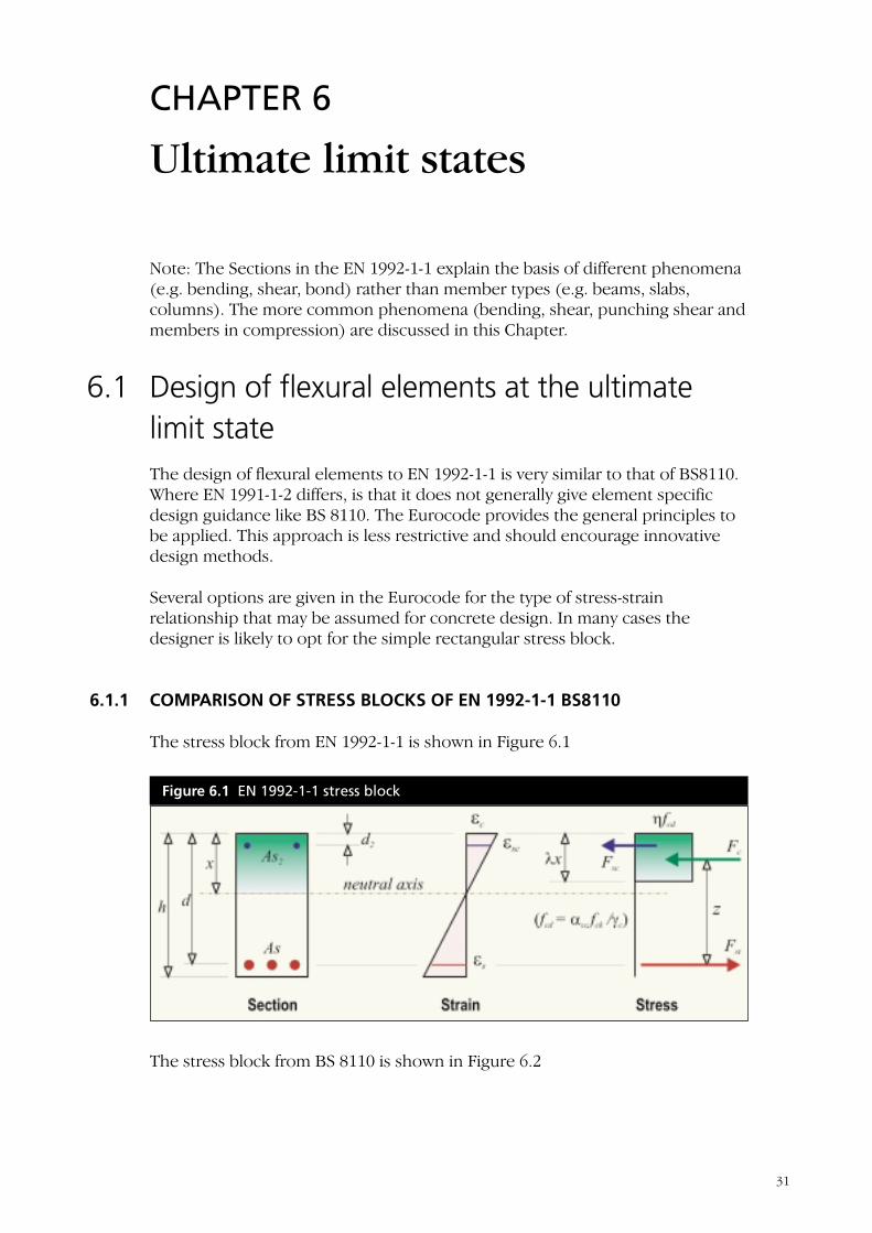
6.1.1 COMPARISON OF STRESS BLOCKS OF EN 1992-1-1 BS8110
The stress block from EN 1992-1-1 is shown in Figure 6.1
The stress block from BS 8110 is shown in Figure 6.2
Figure 6.1 EN 1992-1-1 stress block
31
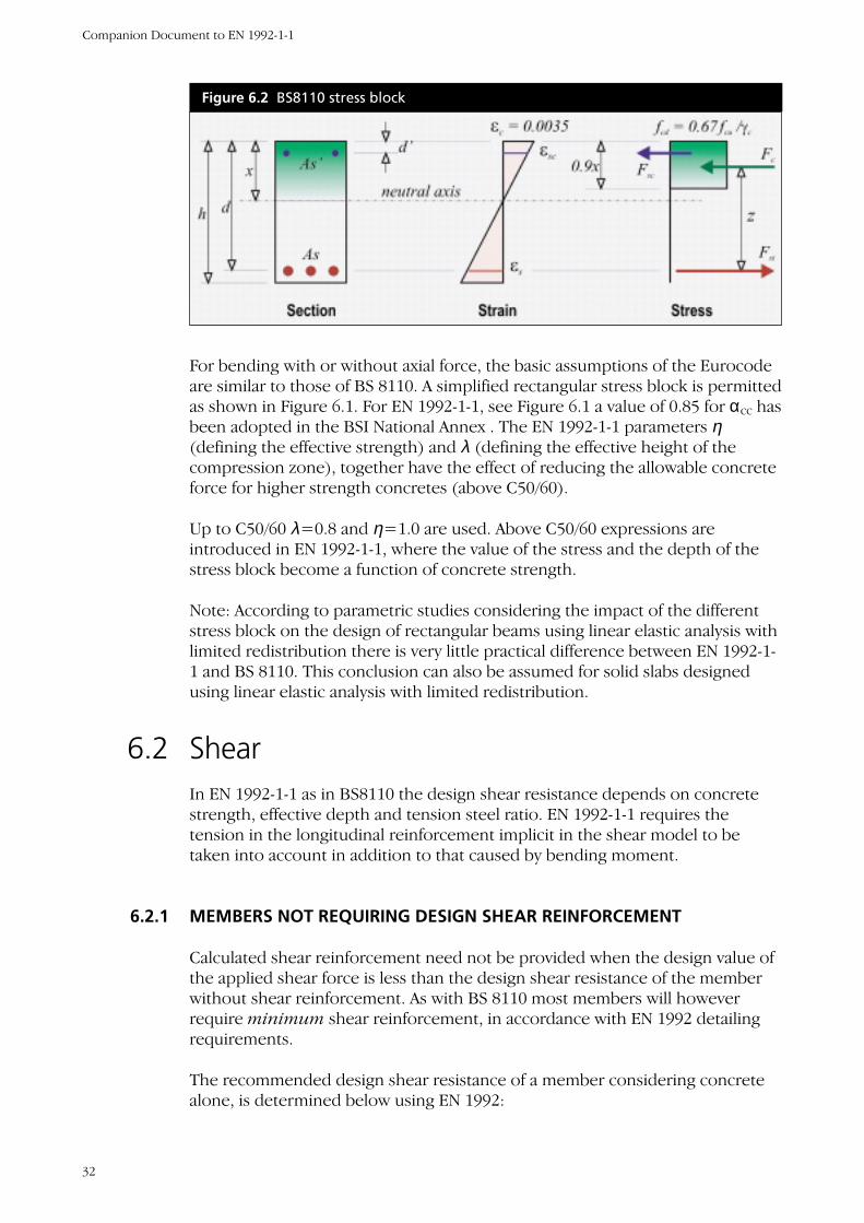
For bending with or without axial force, the basic assumptions of the Eurocodeare similar to those of BS 8110. A simplified rectangular stress block is permittedas shown in Figure 6.1. For EN 1992-1-1, see Figure 6.1 a value of 0.85 for αcc hasbeen adopted in the BSI National Annex . The EN 1992-1-1 parameters η(defining the effective strength) and λ (defining the effective height of thecompression zone), together have the effect of reducing the allowable concreteforce for higher strength concretes (above C50/60).
Up to C50/60 λ=0.8 and η=1.0 are used. Above C50/60 expressions areintroduced in EN 1992-1-1, where the value of the stress and the depth of thestress block become a function of concrete strength.
Note: According to parametric studies considering the impact of the differentstress block on the design of rectangular beams using linear elastic analysis withlimited redistribution there is very little practical difference between EN 1992-1-1 and BS 8110. This conclusion can also be assumed for solid slabs designedusing linear elastic analysis with limited redistribution.
6.2 ShearIn EN 1992-1-1 as in BS8110 the design shear resistance depends on concretestrength, effective depth and tension steel ratio. EN 1992-1-1 requires thetension in the longitudinal reinforcement implicit in the shear model to betaken into account in addition to that caused by bending moment.
6.2.1 MEMBERS NOT REQUIRING DESIGN SHEAR REINFORCEMENT
Calculated shear reinforcement need not be provided when the design value ofthe applied shear force is less than the design shear resistance of the memberwithout shear reinforcement. As with BS 8110 most members will howeverrequire minimum shear reinforcement, in accordance with EN 1992 detailingrequirements.
The recommended design shear resistance of a member considering concretealone, is determined below using EN 1992:
Figure 6.2 BS8110 stress block
Companion Document to EN 1992-1-1
32
for σcp=0
Where k = 1 + √(200/d) ≤ 2
ρl = As/(bd) ≤ 0.02
The value 0.18/γc and the expression for the minimum concrete shear stressvmin are recommended values which may be altered in the National Annex.
With γc = 1.5, comparison with the values of vc given in Table 3.8 of BS8110indicates that, BS 8110 generally allows a higher design shear resistance beforeshear reinforcement is required. EN 1992 can however allow higher designshear resistance for low reinforcement percentages, and this effect isaccentuated the higher the strength of the concrete.
6.2.2 MEMBERS REQUIRING DESIGN SHEAR REINFORCEMENT
Calculated shear reinforcement needs to be provided when the design value ofthe applied shear force is greater than the design shear resistance of themember without shear reinforcement.
EN 1992 differs from BS8110 in that above the limit at which the concrete aloneprovides sufficient capacity, the designed shear steel to be provided isdetermined ignoring the contribution from the concrete.
( ) ckckl
c
cRd fkvfkv 23
31
, 035.0min10018.0
=≥= ργ
Ultimate limit states
33
1/3 3/2
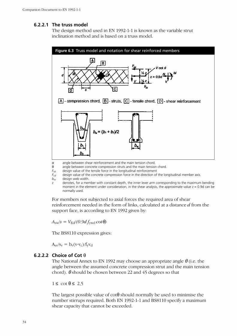
6.2.2.1 The truss modelThe design method used in EN 1992-1-1 is known as the variable strutinclination method and is based on a truss model.
Companion Document to EN 1992-1-1
34
Figure 6.3 Truss model and notation for shear reinforced members
α angle between shear reinforcement and the main tension chord.θ angle between concrete compression struts and the main tension chord.Ftd design value of the tensile force in the longitudinal reinforcementFcd design value of the concrete compression force in the direction of the longitudinal member axis.bw design web width.z denotes, for a member with constant depth, the inner lever arm corresponding to the maximum bending
moment in the element under consideration, in the shear analysis, the approximate value z = 0.9d can benormally used.
For members not subjected to axial forces the required area of shearreinforcement needed in the form of links, calculated at a distance d from thesupport face, is according to EN 1992 given by:
Asw/s = VEd/(0.9d fywd cotθ)
The BS8110 expression gives:
Asv/sv = bv(v-vc)/fyvd
6.2.2.2 Choice of Cot θThe National Annex to EN 1992 may choose an appropriate angle θ (i.e. theangle between the assumed concrete compression strut and the main tensionchord). θ should be chosen between 22 and 45 degrees so that
1 ≤ cot θ ≤ 2,5
The largest possible value of cotθ should normally be used to minimise thenumber stirrups required. Both EN 1992-1-1 and BS8110 specify a maximumshear capacity that cannot be exceeded.
In BS8110 this limit is 0.8√fcu ≤ 5 N/mm2.
For members with vertical shear reinforcement, the maximum possible shearresistance VRd is given by:
VRdmax=αcwbwzνfcd/(cotθ+tanθ) (expression 6.9 of EN 1992-1-1)
where ν = 0.6(1-fck/250)
fcd = αccfck/γc (expression (3.15) of EN 1992-1-1
and αcw=1 for non-prestressed structures
For a given required shear capacity the amount of shear reinforcement to beprovided when designing to EN 1992-1-1 is dependent upon cot θ which shouldbe maximised by equating the design shear force to the maximum possibleshear force VRdmax if cotθ<2.5. The maximum allowable value of cotθ is foundby equating the design shear force VEd to VRdmax.which leads to the followinginequality:
where
Therefore the concrete strength influences the amount of shear reinforcementprovided, if cot θ needs to be less than 2.5 to satisfy the criterion on maximumshear capacity. The maximum possible shear stress corresponds to cotθ=1 andis given by:
VRdmax/bwd=0.45 ν
If the design stress of the shear reinforcement is below 80% of the characteristicyield stress fyk, ν may be taken as:
ν = 0.6 up to C60
ν = 0.9 – fck/200 > 0.5 for grades above C60
EN 1992-1-1 and BS 8110 have been compared with
• αcc = 0.85 and γc =1.5 and
• ignoring the increase allowable for ν if the stress in the shear steel isrestricted.
Ed
cdw
V
fdb νθθω
9.0tancot =+=
5.22
4cot1
2
≤−+=≤ ωωθ
Ultimate limit states
35
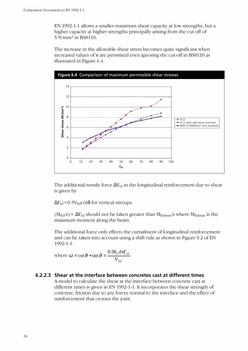
EN 1992-1-1 allows a smaller maximum shear capacity at low strengths, but ahigher capacity at higher strengths principally arising from the cut off of5 N/mm2 in BS8110.
The increase in the allowable shear stress becomes quite significant whenincreased values of ν are permitted even ignoring the cut-off in BS8110 asillustrated in Figure 6.4.
The additional tensile force ∆Ftd in the longitudinal reinforcement due to shearis given by
∆Ftd=0.5VEdcotθ for vertical stirrups.
(MEd/z)+ ∆Ftd should not be taken greater than MEdmax/z where MEdmax is themaximum moment along the beam.
The additional force only effects the curtailment of longitudinal reinforcementand can be taken into account using a shift rule as shown in Figure 9.2 of EN1992-1-1.
where
6.2.2.3 Shear at the interface between concretes cast at different timesA model to calculate the shear at the interface between concrete cast atdifferent times is given in EN 1992-1-1. It incorporates the shear strength ofconcrete, friction due to any forces normal to the interface and the effect ofreinforcement that crosses the joint.
Ed
cdw
V
fdb νθθω
9.0tancot =+=
Figure 6.4 Comparison of maximum permissible shear stresses
0
2
4
6
8
10
12
14
0 10 20 30 40 50 60 70 80 90 100
f ck
Shea
r st
ress
(N
/mm
2)
EC2EC2 shear steel stress restrictedBS8110 (40N/mm2 limit removed)
Companion Document to EN 1992-1-1
36
6.2.3 GENERAL CONCLUSION FOR BEAM SHEAR
EN 1992-1-1 and BS 8110 can in general be expected to give similar results interms of the number and spacing of links to be provided.
6.3 TorsionTorsion resistance is calculated using thin wall section theory, and in the case ofa solid section, the section is converted into an equivalent hollow section fromwhich the resistance is calculated.
6.4 Design of compression elements at theultimate limit stateAs stated in 6.1 EN 1992-1-1, unlike BS 8110, does not give separate guidance fordesigning a column for a known combination of moment and axial force.
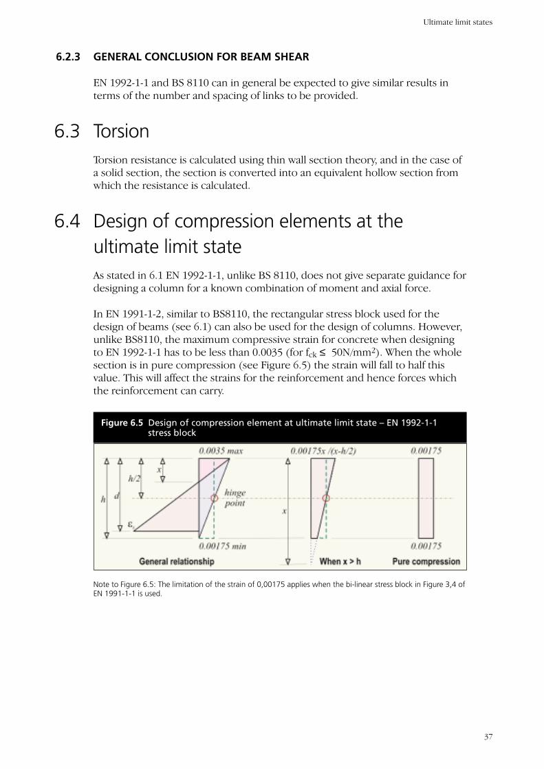
In EN 1991-1-2, similar to BS8110, the rectangular stress block used for thedesign of beams (see 6.1) can also be used for the design of columns. However,unlike BS8110, the maximum compressive strain for concrete when designingto EN 1992-1-1 has to be less than 0.0035 (for fck ≤ 50N/mm2). When the wholesection is in pure compression (see Figure 6.5) the strain will fall to half thisvalue. This will affect the strains for the reinforcement and hence forces whichthe reinforcement can carry.
Note to Figure 6.5: The limitation of the strain of 0,00175 applies when the bi-linear stress block in Figure 3,4 ofEN 1991-1-1 is used.
Figure 6.5 Design of compression element at ultimate limit state – EN 1992-1-1stress block
Ultimate limit states
37
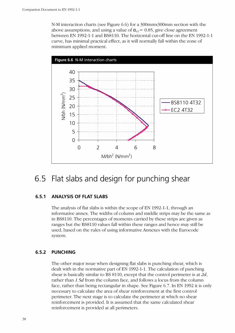
N-M interaction charts (see Figure 6.6) for a 300mmx300mm section with theabove assumptions, and using a value of αcc= 0.85, give close agreementbetween EN 1992-1-1 and BS8110. The horizontal cut-off line on the EN 1992-1-1curve, has minimal practical effect, as it will normally fall within the zone ofminimum applied moment.
6.5 Flat slabs and design for punching shear
6.5.1 ANALYSIS OF FLAT SLABS
The analysis of flat slabs is within the scope of EN 1992-1-1, through aninformative annex. The widths of column and middle strips may be the same asin BS8110. The percentages of moments carried by these strips are given asranges but the BS8110 values fall within these ranges and hence may still beused, based on the rules of using informative Annexes with the Eurocodesystem.
6.5.2 PUNCHING
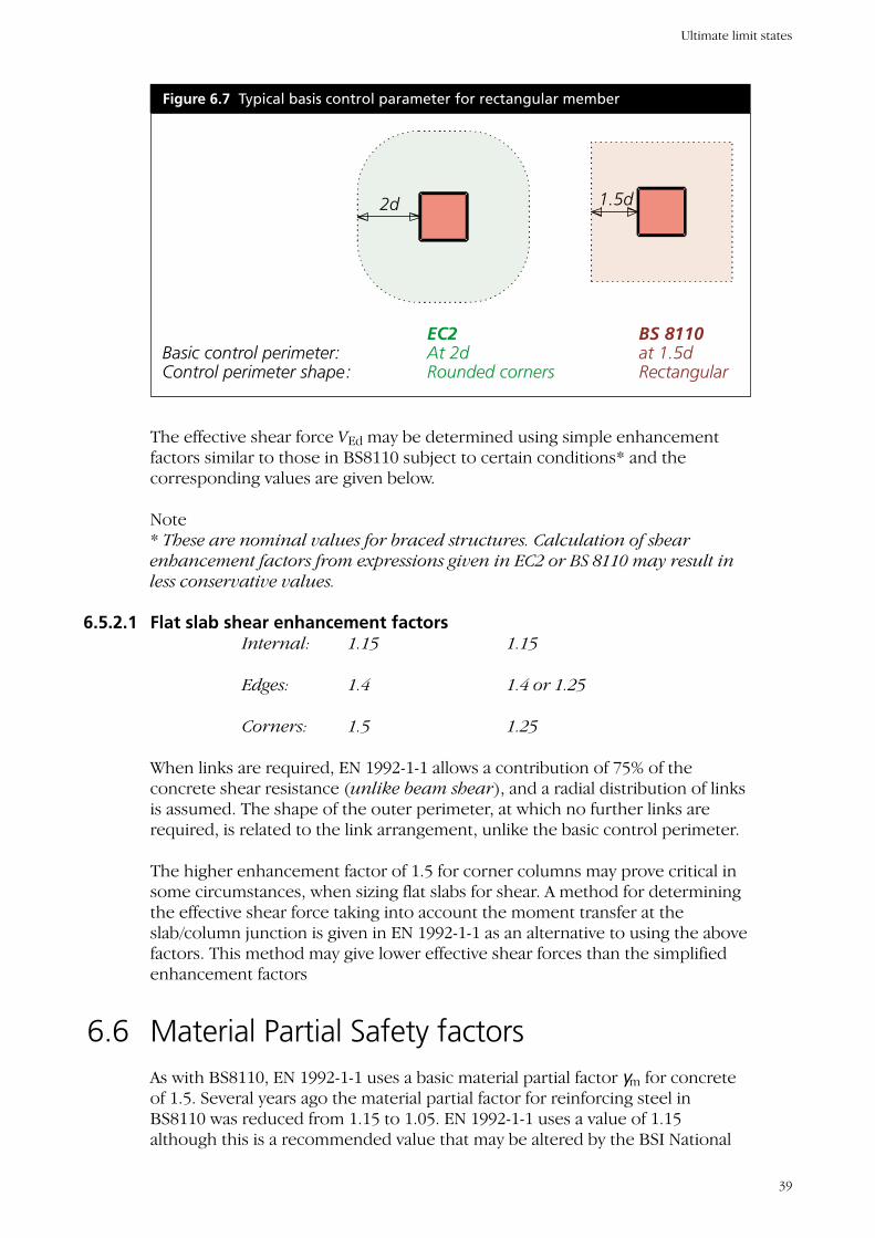
The other major issue when designing flat slabs is punching shear, which isdealt with in the normative part of EN 1992-1-1. The calculation of punchingshear is basically similar to BS 8110, except that the control perimeter is at 2d,rather than 1.5d from the column face, and follows a locus from the columnface, rather than being rectangular in shape. See Figure 6.7. In EN 1992 it is onlynecessary to calculate the area of shear reinforcement at the first controlperimeter. The next stage is to calculate the perimeter at which no shearreinforcement is provided. It is assumed that the same calculated shearreinforcement is provided at all perimeters.
Figure 6.6 N-M interaction charts
0
5
10
15
20
25
30
35
40
0 2 4 6 8
M/bh2 (N/mm2)
N/b
h (N
/mm
2 )
BS8110 4T32EC2 4T32
Companion Document to EN 1992-1-1
38
The effective shear force VEd may be determined using simple enhancementfactors similar to those in BS8110 subject to certain conditions* and thecorresponding values are given below.
Note* These are nominal values for braced structures. Calculation of shearenhancement factors from expressions given in EC2 or BS 8110 may result inless conservative values.
6.5.2.1 Flat slab shear enhancement factorsInternal: 1.15 1.15
Edges: 1.4 1.4 or 1.25
Corners: 1.5 1.25
When links are required, EN 1992-1-1 allows a contribution of 75% of theconcrete shear resistance (unlike beam shear), and a radial distribution of linksis assumed. The shape of the outer perimeter, at which no further links arerequired, is related to the link arrangement, unlike the basic control perimeter.
The higher enhancement factor of 1.5 for corner columns may prove critical insome circumstances, when sizing flat slabs for shear. A method for determiningthe effective shear force taking into account the moment transfer at theslab/column junction is given in EN 1992-1-1 as an alternative to using the abovefactors. This method may give lower effective shear forces than the simplifiedenhancement factors
6.6 Material Partial Safety factorsAs with BS8110, EN 1992-1-1 uses a basic material partial factor γm for concreteof 1.5. Several years ago the material partial factor for reinforcing steel inBS8110 was reduced from 1.15 to 1.05. EN 1992-1-1 uses a value of 1.15although this is a recommended value that may be altered by the BSI National
Figure 6.7 Typical basis control parameter for rectangular member
2d
EC2 BS 8110Basic control perimeter: At 2d at 1.5dControl perimeter shape: Rounded corners Rectangular
1.5d
Ultimate limit states
39
Annex. This is unlikely to have any practical impact however as steel intended tomeet the existing yield strength of 460N/mm2 assumed by BS8110 is likely to beable to meet the 500N/mm2 assumption made by EN 1992-1-1, so that thedesign yield strength fyd will be virtually identical. BS8110 is being revised to bein line with EN 1992 i.e. fy=500N/mm2 and for reinforcement γm=1.15.
For Ultimate limit states.Persistent and transient situations γc = 1.5 γs = 1.15Accidental situations γc = 1.2 γs = 1.00
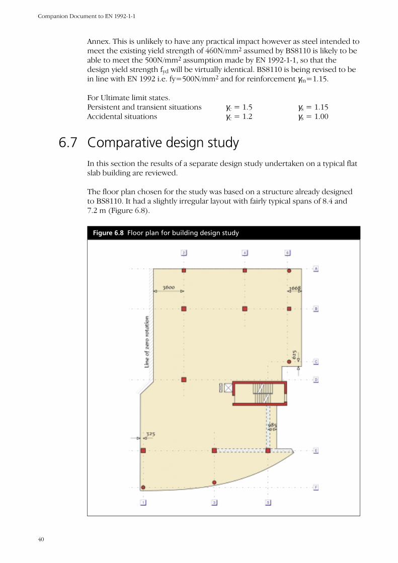
6.7 Comparative design studyIn this section the results of a separate design study undertaken on a typical flatslab building are reviewed.
The floor plan chosen for the study was based on a structure already designedto BS8110. It had a slightly irregular layout with fairly typical spans of 8.4 and7.2 m (Figure 6.8).
Figure 6.8 Floor plan for building design study
Companion Document to EN 1992-1-1
40
A finite element analysis (iterative, cracked section) was used for the design ofthe slabs, because of the irregular column layout. The deflections affecting theperimeter cladding proved to be critical in determining slab thickness.
The determined depth of the slab, required to satisfy the perimeter deflectionlimit, is 260mm for EN 1992-1-1 and 280 mm for BS 8110. There are severalreasons for this difference; the principal reasons being:
• For a specified concrete grade a higher instantaneous modulus ofelasticity EC is given by EN 1992-1-1
• The cracking stress is much higher to EN 1992-1-1 and increases withconcrete strength, but is limited to only 1.0 N/mm2 in BS8110.
The above effects tend to predict smaller displacements with EN 1992-1-1,although these effects are partially offset by a greater density for concrete(25 kN/m3 in the Eurocodes as opposed to 23.6 for BS 8110), 5 mm morebottom cover required for EN 1992-1-1, and the slightly different relationshipbetween support and span steel.
In everyday practice, the above selected slab depths may have been rounded upto the nearest 25mm, giving 275mm and 300mm respectively.
The column load reduction factors given in EN 1992-1-1 were found not to be asgenerous as in BS6399. However the National Annex for EN 1991-1-1 may adoptthe BSI factors.
Column sizes were determined by the maximum amount of verticalreinforcement permitted by each code. In BS 8110 this is 6% (10% at laps) andto EN 1992-1-1, 4% (8% at laps). This resulted in actual column sizes being verysimilar. EN 1992-1-1 does however permit the 4% limit to be exceeded wherethe concrete can still be placed and compacted successfully.
Considering the costs of concrete reinforcement, formwork and excavation,overall construction costs were found to be quite similar between EN 1992-1-1and BS8110. The study [11] used Expressions 6.10a and 6.10b in EN 1990. UsingExpression 6.10 the construction costs using EN 1992-1-1 would have beenslightly higher (of the order of 2-3%), than for BS 8110.
Ultimate limit states
41
CHAPTER 7
Serviceability limit states
7.1 Serviceability design and checksDesign for serviceability is largely concerned with ensuring that the designfunction of the structure is not impaired by the performance of the structure.Serviceability criteria will therefore depend upon the actual planned function ofthe structure and since all design functions cannot be envisaged by a code, thedesigner and his client have the ultimate responsibility for choosing appropriatelimits. The limitations given in EN 1992-1-1 are applicable in most normalcircumstances but it is the responsibility of the designer to check that they areappropriate for the particular structure considered and choose other limits ifthey are deemed more appropriate.
Serviceability checks in EN 1992-1-1comprise stress limitation, crack control anddeflection control.
Regarding stress limitation BSI Codes of Practice on concrete design have notrequired stress checks in reinforced members for over 30 years.
For crack control EN 1992-1-1 gives two methods. Either the bar diameterand/or spacing is limited to the values given for the different stress levels in thereinforcement and crack widths, or detailed calculations are undertaken todemonstrate compliance with acceptance criteria.
For deflection control three methods are available in EN 1992-1-1:
a) span/effective depth limits similar to those in BS 8110;
b) simple calculations based on extensive parametric studies;
c) detailed calculations of deflections taking into account
– concrete tensile strength
– concrete modulus of elasticity
– creep and shrinkage
7.2 Span/depth ratiosIn both BS8110 and EN 1992-1-1 the allowable span/depth ratio depends onconcrete strength and tension and compression reinforcement ratios.
42
Flowcharts that may be downloaded free from www.eurocode2.info show howthe permissible span/depth ratio is arrived at.
A detailed parametric study on span/depth ratios has been carried outcomparing the provisions of the EN 1992-1-1 and BS 8110 in relation to theminimum permitted depth of rectangular beams for a given span. The influenceof increasing the allowable tension steel was considered by allowing a maximumincrease of 100% (i.e. double) than that required for the ultimate limit state,although there is no upper limit stated in EN 1992-1-1 since it was not envisagedthat designers would increase the area of tension reinforcement to reduce slabthickness. The BSI National Annex limits the increase to 50%. The reduction inslab thickness allowed by the span-to-depth rules by increasing the area oftension steel provided over that required, cannot be justified by calculation formore than marginal increases in reinforcement. The 20% redistribution wasassumed for all continuous spans.
The study showed that EN 1992-1-1 tended to be more conservative at lowconcrete strengths. However EN 1992-1-1 tends to permit much higherspan/depth ratios for low reinforcement percentages, even when restricting themaximum enhancement in steel area. In practice however, economic ratherthan minimum permissible depth designs will generally be used, and theseprovide very similar results for both EN 1992-1-1 and BS 8110, depending on theassumptions made. It may not be possible to justify by deflectioncalculation some slab thicknesses given by the EC2 span to depth rulesfor very low reinforcement percentages. The span to depth rules inEC2 do not fully account for the effects of either early age striking orloading from slabs above during construction which may control long-term slab deflections.
7.3 Partial factors for material properties forserviceability limit state verificationsThe partial factors are as follows:
Serviceability limit states. γc = 1.00, γs = 1.00
Serviceability limit states
43
CHAPTER 8
Additional guidance in
EN 1992-1-1 (Sections 8–12
and Annexes)
8.1 Section 8 Detailing of reinforcement – generaland Section 9 Detailing of members andparticular rulesEN 1992-1-1 provides two comprehensive Sections for detailing, and only a fewparticular aspects will be discussed here.
8.1.1 BOND AND ANCHORAGE
The basic bond stress used for the calculation of anchorage and lap lengths is inEN 1992-1-1 depending upon the quality of bond for the position of thereinforcement during concreting, which is also dependent upon the depth ofthe member. The design anchorage length is determined by applying a numberof factors to the basic length, including the shape of the bar, concrete cover andconfinement offered by transverse pressure and reinforcement.
Additional rules apply to large diameter bars (≥ 32mm) where in particular thebond stress is reduced. It is recommended that large diameter bars areanchored using mechanical devices or as straight bars with confiningreinforcement in the form of links.
8.1.2 DETAILING RULES
EN 1992-1-1 gives detailing rules for various member types. Maximum andminimum percentages of reinforcement, spacing rules etc are given for slabs,beams, columns, walls, deep beams and flat slabs.
8.1.3 ROBUSTNESS AND TYING REQUIREMENTS
Tying requirements for robustness in EN 1992-1-1 are given and these are similarto those in BS 8110, with requirements for peripheral, internal and horizontalcolumn or wall ties but vertical ties are required only in panel buildings of 5
44
storeys or more. These particular rules are however superseded by theApproved Document A guidance on disproportionate collapse. EN 1992-1-1allows for the provisions to ensure robustness to be altered by the NationalAnnex.
8.1.4 ADDITIONAL REQUIREMENTS
a) The spacing rules in EN 1992-1-1 may lead to more and smaller bars, unlesscrack widths are checked, than for BS 8110.
b) There is a requirement in EN 1992-1-1 that beam top steel should bedistributed across flanges (both tension and compression).
8.2 Section 10 Precast concrete elements andstructuresEN 1992-1-1 permits reduced partial factors for materials γc and γs provided thisis justified by adequate control procedures.
8.3 Section 11 Lightweight aggregate concretestructuresEN 1992-1-1 gives clear guidance on density and material properties.
The design methods for lightweight concrete are the same as the designmethods for dense concrete although EN 1992-1-1 gives modifiedrecommended values for many factors, including αcc and αct
8.4 Section 12 Plain and lightly reinforcedconcrete structuresThis Section provides simplified design equations for plain and lightlyreinforced concrete structures, such as strip footings or walls.
8.5 Materials and WorkmanshipEN 1992-1-1 does not cover materials and workmanship and a separateExecution Standard has been prepared. This is currently in ENV form and anational document based on the existing National Structural ConcreteSpecification [10] is in preparation.
One issue, which however is specifically referred to in EN 1992-1-1, is thetolerance on cover. Cover to meet durability and bond requirements is specifiedas a minimum value with a tolerance of up to 10mm to be added on top. This
Additional guidance in EN 1992-1-1 (Sections 8-12 and Annexes)
45
is in contrast to BS8110 where cover is specified as a nominal value and atolerance of 5mm accepted. In situations where good quality control isexercised (e.g. factory produced precast beams) there is scope for reducing thetolerance.
8.6 Annexes to EN 1992-1-1EN 1992-1-1 has the following Annexes.
A (Informative) Modification of partial factors for materials
B (Informative) Creep and shrinkage strain
C (Normative) Reinforcement properties
D (Informative) Detailed calculation method for prestressing steel relaxationlosses
E (Informative) Indicative strength classes for durability
F (Informative) Reinforcement expressions for in-plane stress conditions
G (Informative) Soil structure interaction
H (Informative) Global second order effects in structures
I (Informative) Analysis of flat slabs and shear walls
J (Informative) Examples of regions with discontinuity in geometry or action
Companion Document to EN 1992-1-1
46
CHAPTER 9
Conclusions
9.1 Availability of Guidance for EN 1992-1-1
9.1.1 HANDBOOKS, MANUALS, AND CONCISE EUROCODES
H Gulvanessian, J-A Calgaro and M Holiky: Designers Guide to EN1990: Eurocode: Basis of Structural Design, Thomas TelfordPublications 2002.
A W Beeby and R S Narayanan: Designers Handbook to Eurocode 2Part 1.1, Design of Concrete Structures, Thomas Telford, London, 1995
These two handbooks produced as part of the Eurocode Design Handbooksseries published by Thomas Telford is aimed at designers, at all professionallevels, involved in the design of reinforced or prestressed concrete using theENV version of the Eurocode. It provides advice to designers through anexplanation of the background to and the intention of the clauses of theparticular Eurocode.
Institution of Structural Engineers, Manual for the Design ofReinforced Concrete Building Structures to EC2
The manual will use the format of the green book (Manual for BS8110). As withthe green book the scope of the manual covers the majority of concretebuilding structures and has now been extended to cover slender columns andprestressed concrete. An appendix for the structural design of foundationsusing limit state philosophy has also been included.
9.1.2 AVAILABILITY OF OTHER DESIGN AIDS
A suite of practical design aids to assist practising engineers to become familiarwith and apply the code is currently in course of preparation. These include:
1. A set of Excel based spreadsheets, to complement the existing highlypopular set of spreadsheets to BS8110 produced by the Concrete Centre(TCC)
2. A series of How to Design Leaflets explaining the basic design concepts forprimary structural elements available on-line and to be freely distributed.
47
3. A concise code summarising the key information within the code requiredfor everyday use and appropriate values from and references to othersupporting codes
4. Worked Examples for the Design of Concrete Buildings
A helpline facility is planned to be set up so that frequently asked questions canbe answered and a dedicated website www.eurocode2.info is now on-line andwill be expanded to provide links to available sources of information. This willcomplement other activities such as the RCC’s Concrete Computer AidedLearning package.
9.1.3 EUROCODE EXPERT AND THE INSTITUTION OF CIVIL ENGINEERS
Eurocode expert with its comprehensive website www.eurocodes.co.ukprovides up to date information on the latest situation with regard to thedevelopment and implementation of the Eurocodes, with information onguidance documents, training courses etc. See also the special Eurocodes issuepublished by the Institution of Civil Engineers [12].
9.2 Impact on the professionThe implementation of the Eurocodes in the UK will provide opportunities tothe UK profession, as they are foreseen to
• Improve the functioning of the single market for products and engineeringservices, by removing obstacles arising from different nationally codifiedpractices for the assessment of structural reliability
• Improve the competitiveness of the European construction industry, andthe professionals and industries connected to it, in Countries outside theEuropean Union.
Calibration studies have shown that the differences in cost between structuresand members designed to EN 1992 and BS 8110 is neutral. With regard to theuse of EN 1992 there are differences between the Eurocodes and current UKpractice that could increase the cost of design during the initial learning curve.In particular, EN 1992-1-1 explain the basis of different phenomena (e.g.bending, shear, bond) rather than member types (e.g. beams, slabs, columns)explained in BS 8110.
Differences in practice (e.g. specifying a cylinder strength) may necessitatebetter communication between the designer and the contractor.
9.3 Concluding remarks1. The implementation of the Eurocodes including EN 1992-1-1 for the design
of all types of structures will have a big impact on the UK profession. There
Companion Document to EN 1992-1-1
48
will be a learning curve associated with training, gaining familiarity andusing the new codes.
2. Design aids and information will assist the profession duringimplementation.
3. In general EN 1992-1-1, used with the National Annex, gives similar solutionsto BS 8110 and additionally offers scope for more economic structures.
4. Overall EN 1992-1-1 is less prescriptive and its scope is more extensive thanBS8110 for example in permitting higher concrete strengths. In this sensethe new code will permit designs not currently permitted in the UK, andthus give designers the opportunity to derive benefit from the considerableadvances in concrete technology over recent years. It is considered that,after an initial acclimatisation period, the implementation of EN 1992-1-1will be generally regarded as a very good code and a step in the rightdirection.
5. Some of the main differences between the EN 1992-1-1 and BS 8110described in this document are summarised below:
• EN 1992-1-1 allows for the use of high strength concretes, which BS8110does not
• Concrete strengths are classified by cylinder strengths which aretypically 10-20% less than the corresponding cube strength
• In EN 1992-1-1 cover for durability and bond requirements is specifiedas a minimum value whereas BS8110 specifies a nominal value
• Durability considerations are considered in a more explicit manner inthe EN 1992-1-1. The concept of an explicitly defined design life isincluded and the designer is required to identify the most severeenvironmental conditions for each particular case
• The material partial safety factor for concrete will remain the same asthe BS 8110 value (Υm,conc = 1.5). Although there is a small change inthe material factor for reinforcing steel this will have little practicalimpact and the recommended EN 1992-1-1 value of Υm,steel = 1.15 islikely to be adopted in the UK National Annex
• Load combination expressions and values for partial factors for loadingare given in EN 1990
• A slightly higher value for the density of normal weight concrete isassumed. Preliminary studies1 indicate that the overall impact of usingEN 1992-1-1 in this area will be minimal
• The Sections in the EN 1992-1-1 explain the basis of differentphenomena (e.g. bending, shear, bond) rather than member types (e.g.beams, slabs, columns) as in BS 8110
Conclusions
49

• For the design of flexural elements at the ultimate limit state preliminarystudies indicate that there is very little practical difference between EN1992-1-1 and BS8110
• In terms of shear resistance of beams EN 1992-1-1 differs from BS8110 inthat above the limit at which concrete alone has sufficient capacity, thedesigned shear steel to be provided is determined ignoring thecontribution from the concrete.
Companion Document to EN 1992-1-1
50
REFERENCES
1. Guidance Paper L (concerning the Construction Products Directive –89/106/EE) – Application and Use of Eurocodes: The EuropeanCommission; 2004. Director General Enterprises – European Commission
2. Commission Recommendation of 11 December 2003 on theimplementation and use of Eurocodes for Construction Works andConstruction Products. Office of the European Union ppL 332/62 – 63
3. EN 1992-1-1: 1992: Eurocode 2: Part 1.1: General rules and rules forbuildings: BSI 2005
4. EN 1990: Eurocode: Basis of structural design. BSI 2002
5. Gulvanessian, Calgaro and Holicky: Designers guide to EN 1990:Eurocode: Basis of structural design. Thomas Telford 2002
6. Guide to the use of EN 1990, EN 1991-1-4 and EN 1991-1-7. BRE 2005
7. EN 206-1: Concrete; Specification, performance, production andconformity. BSI 2004
8. EN 1991-1-1: Eurocode 1: Actions on structures: Densities, self weight andimposed loads. BSI 2002
9. Gulvanessian and Holicky: Combination of action effects for theEurocodes. To be published. Proceedings of the Institution of CivilEngineers: Structures and Buildings. 2005
10. National Structural Concrete Specification for Building Construction,Second Edition, BCA Publication 97.378, July 2000.
11. BS 8500: Part 2: Concrete: Complementary British standard to BSEN 206-1.BSI 2002
12. EUROCODES, Proceedings of the Institution of Civil Engineers, CivilEngineering Special issue Two, November 2001, Volume 144
13. Webster R, Reinforced concrete framed structure: Comparative designstudy to EN 1992 and BS8110, BRE Report BR455, 2003
14. Moss R and Webster R, EN 1992 and BS 8110 compared, The StructuralEngineer, ISE 2004.
51