Embed Size (px)
Citation preview

EUROPEAN ORGANISATIONFOR THE SAFETY OF AIR NAVIGATION
EUROCONTROL EXPERIMENTAL CENTRE
SOFTStudy of Operational Flight Plans and Trajectories
Requirements for Advanced Flight Plan Information
EEC Note No. 14/98
EEC Task R23EATCHIP Task ODP-5-E3
Issued: June 1998
The information contained in this document is the property of the EUROCONTROL Agency and no part should be reproduced inany form without the Agency’s permission.
The views expressed herein do not necessarily reflect the official views or policy of the Agency.
EUROCONTROL
REPORT DOCUMENTATION PAGE
Reference:EEC Note No. 14/98
Security Classification:Unclassified
Originator:EEC - FDR(Flight Data Research)
Originator (Corporate Author) Name/Location:EUROCONTROL Experimental CentreBP1591222 Brétigny-sur-Orge CEDEXFRANCETelephone : +33 (0)1 69 88 75 00
Sponsor:EATCHIP Development DirectorateDED.2
Sponsor (Contract Authority) Name/Location:EUROCONTROL AgencyRue de la Fusée, 96B -1130 BRUXELLESTelephone : +32-(0)2-729 90 11
TITLE:SOFT
Study of Operational Flight Plans ans TrajectoriesRequirements for Advanced Flight Plan Information
AuthorR. Schuppenhauer
Date
6/98Pages
xii + 92Figures
12Tables
13Appendix
6References
34
EATCHIP TaskSpecification
ODP-5-E3
EEC Task No.
R23
Task No. Sponsor Period
1997
Distribution Statement:(a) Controlled by: Head of FDR(b) Special Limitations: None(c) Copy to NTIS: YES / NO
Descriptors (Keywords):
Flight Plan, Business Objects, Trajectory
Abstract:
This diploma thesis was written in the of a collaboration agreement between the EUROCONTROLExperimental Centre (EEC) in Brétigny-sur-Orge and the research group ComputergestützteInformationssysteme (CIS) of Technische Universität Berlin. It proposes the definition of a business objectthat realises extended flight plan functionality/information. This business object would allow for moreprecise prediction of aircraft trajectories and thus for optimised use of the already overcrowded airspace inEurope.
A flight plan represents the basic contract between a pilot and air traffic control. However, the currentformat for filed flight plans contains only limited information with equally limited precision about flights,while the airlines have access to significantly more detailed data. This extended flight plan functionalitymakes use of information about aircraft already available to airline pilots but not communicated to airtraffic control.
The thesis aims to demonstrate that an enhanced set of flight plan information would assist air trafficcontrol in their tactical decisions and that different analyses of radar data and flight plans might giveresearchers a better understanding of the causes of discrepancies between predicted and realisedtrajectories.

This document has been collated by mechanical means. Should there be missing pages, please report to:
EUROCONTROL Experimental CentrePublications Office
B.P. 1591222 - BRETIGNY-SUR-ORGE CEDEX
France
REQUIREMENTSDEFINITION FORADVANCED FLIGHT PLAN INFORMATION
V
EUROCONTROL
CONTENTSABBREVIATIONS ................................................................................................................. VII
LIST OF FIGURES .....................................................................................................................X
PREFACE ................................................................................................................................. XI
1. INTRODUCTION...............................................................................................11.1 Air Traffic Control and Information Technology............................................ 11.2 The SOFT Project .....................................................................................................1.3 Business Object Developed in this Paper ......................................................... 41.4 Outline of the Thesis ............................................................................................. 5
2. THE PROBLEM DOMAIN 62.1 The Situation in Flight Planning Today............................................................ 62.2 EUROCONTROL Strategy .......................................................................................... 8
3. BUSINESS OBJECTS:MODULAR REUSABLE STRUCTURES ...........................................................12
4. REQUIREMENTS DEFINITION FOR A FLIGHT PLAN BUSINESS OBJECT ..174.1 User Requirements .............................................................................................. 18
4.1.1 Airlines ..................................................................................................... 184.1.2 Airports ..................................................................................................... 194.1.3 Area Control Centres.............................................................................. 204.1.4 BADA ........................................................................................................ 244.1.5 CFMU ........................................................................................................ 254.1.6 CRCO ........................................................................................................ 274.1.7 DIFODAM ................................................................................................ 284.1.8 FREER ....................................................................................................... 294.1.9 FAA’s “New Age Flight Plan” .............................................................. 30
4.2 Classification of User Requirements ................................................................ 32
5. DEVELOPMENT OF AN XFPL BUSINESS OBJECT ........................................405.1 Definition of an XFPL Format ........................................................................... 415.2 Mapping the XFPL Object to the Relational Data Model ............................ 52
6. EVALUATION OF THE XFPL BUSINESS OBJECT ........................................706.1 Results .................................................................................................................... 706.2 Strategies for the Evaluation of the Business Object .................................... 70
6.2.1 Comparison of Trajectories .................................................................... 70
7. CONCLUSION ................................................................................................72
ANNEX I: THE ICAO FILED FLIGHT PLAN FORMAT .................................... 74
ANNEX II: OPERATIONAL FLIGHT PLANS ....................................................75

REQUIREMENTSDEFINITION FORADVANCED FLIGHT PLAN INFORMATION
VI
EUROCONTROL
ANNEX III: SYSTEM FLIGHT PLANS OF THE AREA CONTROL CENTRES ....78
ANNEX IV: RADAR DATA DESCRIPTION .......................................................80
ANNEX V: METEOROLOGICAL DATA............................................................81
ANNEX VI: CFMU DATA ...............................................................................82REFERENCES .......................................................................................................................... 84
GLOSSARY ............................................................................................................................. 87
REQUIREMENTSDEFINITION FORADVANCED FLIGHT PLAN INFORMATION
VII
EUROCONTROL
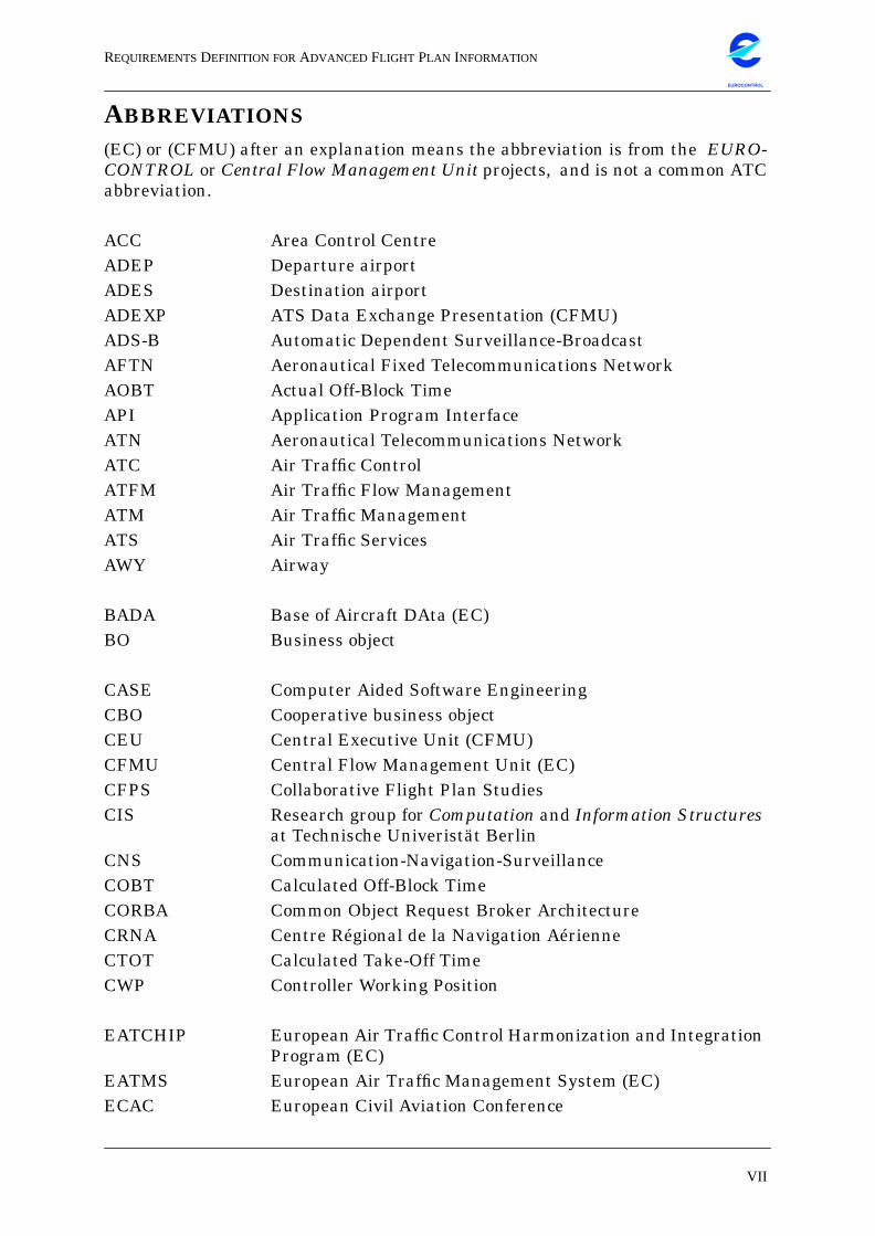
ABBREVIATIONS(EC) or (CFMU) after an explanation means the abbreviation is from the EURO-CONTROL or Central Flow Management Unit projects, and is not a common ATCabbreviation.
ACC Area Control CentreADEP Departure airportADES Destination airportADEXP ATS Data Exchange Presentation (CFMU)ADS-B Automatic Dependent Surveillance-BroadcastAFTN Aeronautical Fixed Telecommunications NetworkAOBT Actual Off-Block TimeAPI Application Program InterfaceATN Aeronautical Telecommunications NetworkATC Air Traffic ControlATFM Air Traffic Flow ManagementATM Air Traffic ManagementATS Air Traffic ServicesAWY Airway
BADA Base of Aircraft DAta (EC)BO Business object
CASE Computer Aided Software EngineeringCBO Cooperative business objectCEU Central Executive Unit (CFMU)CFMU Central Flow Management Unit (EC)CFPS Collaborative Flight Plan StudiesCIS Research group for Computation and Information Structures
at Technische Univeristät BerlinCNS Communication-Navigation-SurveillanceCOBT Calculated Off-Block TimeCORBA Common Object Request Broker ArchitectureCRNA Centre Régional de la Navigation AérienneCTOT Calculated Take-Off TimeCWP Controller Working Position
EATCHIP European Air Traffic Control Harmonization and IntegrationProgram (EC)
EATMS European Air Traffic Management System (EC)ECAC European Civil Aviation Conference
REQUIREMENTSDEFINITION FORADVANCED FLIGHT PLAN INFORMATION
VIII
EUROCONTROL
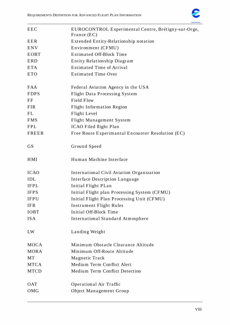
EEC EUROCONTROL Experimental Centre, Brétigny-sur-Orge,France (EC)
EER Extended Entity-Relationship notationENV Environment (CFMU)EOBT Estimated Off-Block TimeERD Entity Relationship DiagramETA Estimated Time of ArrivalETO Estimated Time Over
FAA Federal Aviation Agency in the USAFDPS Flight Data Processing SystemFF Field FlowFIR Flight Information RegionFL Flight LevelFMS Flight Management SystemFPL ICAO Filed flight PlanFREER Free Route Experimantal Encounter Resolution (EC)
GS Ground Speed
HMI Human Machine Interface
ICAO International Civil Aviation OrganizationIDL Interface Description LanguageIFPL Initial Flight PLanIFPS Initial Flight plan Processing System (CFMU)IFPU Initial Flight Plan Processing Unit (CFMU)IFR Instrument Flight RulesIOBT Initial Off-Block TimeISA International Standard Atmosphere
LW Landing Weight
MOCA Minimum Obstacle Clearance AltitudeMORA Minimum Off-Route AltitudeMT Magnetic TrackMTCA Medium Term Conflict AlertMTCD Medium Term Conflict Detection
OAT Operational Air TrafficOMG Object Management Group
REQUIREMENTSDEFINITION FORADVANCED FLIGHT PLAN INFORMATION
IX
EUROCONTROL
OOA Object-Oriented AnalysisOOD Object-Oriented Design
PRE-TACT Pre-Tactical system (CFMU)RDPS Radar Data Processing SystemRFL Requested Flight LevelRPL ICAO Repetitive flight PLanRTCA Radio-Technical Commission for Aeronautics
SAM Slot Allocation Message (CFMU)SFPL System Flight PlanSID Standard Instrument DepartureSIP Slot Improvement Proposal message (CFMU)SITA Société Internationale de Télécommunication AéronautiqueSSR Secondary Surveillance RadarSTAR STandard (instrument) ARrivalSTIP Système de Traitement Initial de Plans de VolSTRAT STRATegic System (CFMU)
TACT Tactical System (CFMU)TAS True Air SpeedTMA Terminal Manoeuvre AreaTMP TemperatureTOW Take-Off WeightTWR Aerodrome control ToWeR
UAC Upper Area Control centreUTC Universal Time Co-ordinated
VFR Visual Flight Rules
WAN Wide Area NetworkWCA Wind Correction AngleWPT Waypoint
XFPL Extended Flight Plan
ZFW Zero Fuel Weight
REQUIREMENTSDEFINITION FORADVANCED FLIGHT PLAN INFORMATION
X
EUROCONTROL
LIST OF FIGURES
Figure 1: The XFPL Object 44Figure 2: XFPL Aggregation 45Figure 3: Model and View 46Figure 4: XFPL Model and View 47Figure 5: Client Views 48Figure 6: Database Adapter 49Figure 7: Persistence Pattern 50Figure 8: State Model 51Figure 9: Mapping of the Object Class Model 52Figure 10: A simplified flight plan relation 53Figure 11: flight plan formats Object Model 54Figure 12: ER-Diagram of the SOFT Database 57
REQUIREMENTSDEFINITION FORADVANCED FLIGHT PLAN INFORMATION
XI
EUROCONTROL
PREFACEThis diploma thesis was written in the frame of a cooperation agreement
between the Eurocontrol Experimental Centre (EEC) in Brétigny-sur-Orge and
the research group Computergestützte Informationssysteme (CIS) of Technische
Universität Berlin. It was conducted as a sub-project of SOFT (Study of Opera-
tional Flight Plans and Trajectories).
The thesis proposes the definition of a business object that realizes extended
flight plan functionality/information. This business object would allow for more
precise prediction of aircraft trajectories and thus for optimized use of the already
overcrowded airspace in Europe.
A flight plan represents the basic contract between a pilot and air traffic control.
However, the current format for filed flight plans contains only limited informa-
tion with equally limited precision about flights, while the airlines have access to
significantly more detailed data. This extended flight plan functionality makes
use of information about aircraft already available to airline pilots but not com-
municated to air traffic control.
The thesis aims to demonstrate that an enhanced set of flight plan information
would assist air traffic control in their tactical decisions and that different analy-
ses of radar data and flight plans might give researchers a better understanding
of the causes of discrepancies between predicted and realized trajectories.

REQUIREMENTSDEFINITION FORADVANCED FLIGHT PLAN INFORMATION
XII
EUROCONTROL
Intentionally left blank.
REQUIREMENTSDEFINITION FORADVANCED FLIGHT PLAN INFORMATION
AIR TRAFFIC CONTROL AND INFORMATION TECHNOLOGY 1
EUROCONTROL
1. INTRODUCTION
1.1 Air Traffic Control and Information Technology
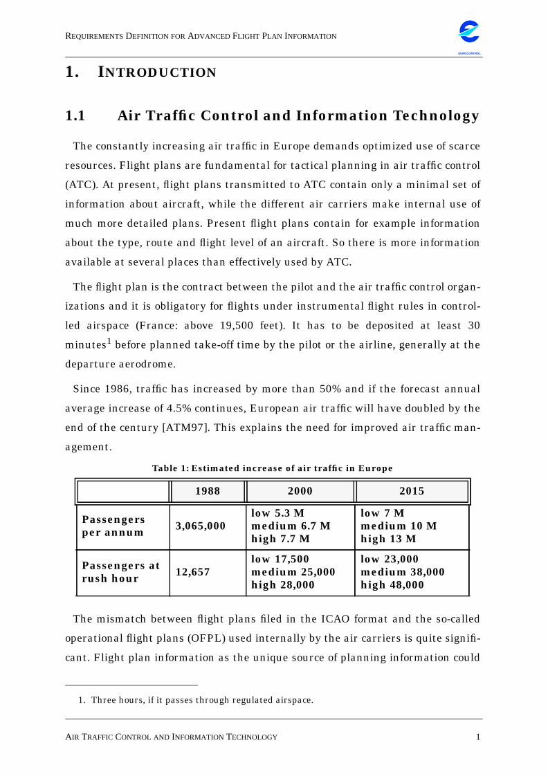
The constantly increasing air traffic in Europe demands optimized use of scarce
resources. Flight plans are fundamental for tactical planning in air traffic control
(ATC). At present, flight plans transmitted to ATC contain only a minimal set of
information about aircraft, while the different air carriers make internal use of
much more detailed plans. Present flight plans contain for example information
about the type, route and flight level of an aircraft. So there is more information
available at several places than effectively used by ATC.
The flight plan is the contract between the pilot and the air traffic control organ-
izations and it is obligatory for flights under instrumental flight rules in control-
led airspace (France: above 19,500 feet). It has to be deposited at least 30
minutes1 before planned take-off time by the pilot or the airline, generally at the
departure aerodrome.
Since 1986, traffic has increased by more than 50% and if the forecast annual
average increase of 4.5% continues, European air traffic will have doubled by the
end of the century [ATM97]. This explains the need for improved air traffic man-
agement.
The mismatch between flight plans filed in the ICAO format and the so-called
operational flight plans (OFPL) used internally by the air carriers is quite signifi-
cant. Flight plan information as the unique source of planning information could
1. Three hours, if it passes through regulated airspace.
Table 1: Estimated increase of air traffic in Europe
1988 2000 2015
Passengersper annum 3,065,000
low 5.3 Mmedium 6.7 Mhigh 7.7 M
low 7 Mmedium 10 Mhigh 13 M
Passengers atrush hour 12,657
low 17,500medium 25,000high 28,000
low 23,000medium 38,000high 48,000
REQUIREMENTSDEFINITION FORADVANCED FLIGHT PLAN INFORMATION
THE SOFT PROJECT 2
EUROCONTROL
be enhanced by the tactical decisions that air carriers have taken for flight trajec-
tories, which are fed into sophisticated Flight Management Systems (FMS) in
each aircraft.
Trajectories and their distribution are considered to be a very important feature
of the next generation of flight data processing systems (FDPS). There are differ-
ent proposals as to how the trajectories should be calculated and distributed. Cur-
rently the EEC is working on several projects in this direction, one of which is the
SOFT project in which the author had the opportunity to participate. This thesis
aims to find out if adding further detail would permit more efficient air traffic
management and more precise prediction for the controllers on the ground and
increase their work efficiency.
Meanwhile, progress in computer science in recent years has coined the term
Common (or Cooperative) Business Object, or business object for short. Unlike
objects and classes in object-oriented programming languages, business objects
(BO) represent things or concepts relevant to an application domain. They are
self-contained deliverables that can cooperate with other, separately developed
BOs.
1.2 The SOFT Project
This diploma thesis reflects a part of the Study of Operational Flight Plans and Trajec-
tories (SOFT) which itself is part of the Collaborative Flight Plan Studies (CFPS)
project which began in May 1997 at the EEC in Brétigny-sur-Orge.
In the Centre of Expertise Flight Data Research (FDR) at the EEC scientists and engi-
neers are studying the benefits that could result from an intensified data exchange
between air carriers and air traffic management. The exchange of operationally signif-
icant information between the ATC systems and the airspace users is not being used
to its full capacity. AOCs have access to detailed operational data [FMS95] while
ATFM disposes of data that would help the AOCs in planning their operations in a
more efficient manner. Although there is a significant amount of data available, only a
small part of this data is actually being exchanged today. Also this exchange is largely
non-automated, e.g. telephone conversations between airline dispatchers and traffic
REQUIREMENTSDEFINITION FORADVANCED FLIGHT PLAN INFORMATION
THE SOFT PROJECT 3
EUROCONTROL
management personnel are still common practice.
The project is motivated by the assumption that an exchange of the data currently
available to ATM and to the different AOCs can be quickly, easily and inexpensively
initiated today. The use of airline data could lead to improved trajectory handling in
future FDPS. Today the trajectory calculation in ground-based FDPS is based initially
on the FPL obtained by the IFPS. Interviews with different air carriers have shown
that the cockpit FMS provide enhanced trajectory predictions both before take-off and
in-flight (for long-range flights).
At the beginning of the project contacts to all the different potential providers of
data had to be established. Air France, British Airways, Condor, KLM, LTU,
Lufthansa, OAL, SAS, Swissair, and TAT have provided their OFPLs. In addition to
these airlines, SITA was contacted as a provider for flight plans from several other air-
lines, e.g. UK Air and Syrian Airlines. Then the Centre Régional de Navigation Aéri-
enne (CRNA) Reims, as well as the CRNA in Athis-Mons were contacted to provide
radar data and corresponding system flight plans (SFPL). The CFMU in Brussels sent
flight plans in the so-called All_Flights format, and Météo France provided meteoro-
logical data for the ECAC region.
A detailed description of the contents of all the different data formats is given in
the Annexes. The 17th of June 1997 was chosen for the actual data collection.
Once all the data had arrived at the EEC, an analysis of the different formats and
of the semantics of the data fields was initiated. Interviews with aeronautics spe-
cialists at the EEC allowed data of genuine relevance to be filtered from data of
merely internal importance.
All the collected data had to be stored in a persistent form, so it was decided to
create a database to which the relevant data should be transferred. The choice
between a relational and an object-oriented database was made with respect to
the available database management systems at the EEC. PERL was the chosen
programming language [WCS96] for parsing and extracting information from the
large files, because a freely available database interface exists between PERL
scripts and ORACLE databases.
REQUIREMENTSDEFINITION FORADVANCED FLIGHT PLAN INFORMATION
BUSINESSOBJECTDEVELOPED IN THISPAPER 4
EUROCONTROL
1.3 Business Object Developed in this PaperWe are trying to find a means for optimization of the existing ATC system by
defining common, modular and reusable business objects as a design option for
future systems. Following the ideas of Oliver Sims [Sim94] the ATC domain can
be decomposed into prototypical business objects. Focusing on flight plans, as the
central information source for pilot intentions, requirements for the definition of
such business objects have to be detected.
The shift in paradigm from monolithic systems to reusable independent compo-
nents will result in new architectures for industry-scale systems. The central
objective of this thesis is the definition of a common and reusable business object
to be used in a distributed architecture for the ATC domain. The ATC domain can
be decomposed into prototypical BOs. With special regard to flight plans, require-
ments for the definition of business objects have to be elicited. This raises the fol-
lowing questions:
• How should the clients’ various requirements be classified?
• What are relevant information sources for the definition of ATC BOs?
• How can the different data formats be adequately reflected in future BOs?
• Which aspects concerning the operational environment of the BO may influ-
ence its design?
Consequently, this thesis shall propose business objects for the ATC domain
with special regard to flight plans. On the basis of the “SOFT” project, existing
data sources have to be evaluated and their relationships to requirements defined
by a set of clients/actors have to be studied. The available information sources,
e.g. operational flight plans provided by different airlines, have to be analysed
with respect to their structure and semantics. Relating the requirements of indi-
vidual actors/clients to the available information analysed in the previous phase
will outline the structural requirements for the BO.
REQUIREMENTSDEFINITION FORADVANCED FLIGHT PLAN INFORMATION
OUTLINE OF THE THESIS 5
EUROCONTROL
1.4 Outline of the Thesis
First I would like to present an introduction to the subject treated in this thesis,
followed by an outline of the problem domain, i.e. air traffic control in Europe, and
in particular the use of flight plans for air traffic flow management and control. In
the first part of this chapter I will describe the current situation including the dif-
ferent phases and format transformations in the existence of a flight plan, its dif-
ferent users, the authorities involved in controlling and managing air traffic as
well as the problems that occur due to the constantly increasing number of flights
in Europe. The second part of the chapter will treat research strategies followed
by the EEC [EMS97] that propose to resolve these problems, followed by a brief
sketch of the research project FREER that might one day bring a complete change
to the way air traffic control is organized.
Then I will describe the benefits of the use of business objects as modular reusable
software structures and I will give a technical description of a BO.
The main part of the thesis begins with the evaluation of the requirements of poten-
tial users and clients of such a business object, where the focus remains on structural
aspects. After this, I will give a classification of these requirements.
The classification of the users’ requirements will then lead to the definition of the
eXtended Flight PLan (XFPL) as a business object that integrates the user require-
ments. For this CBO I will also propose an infrastructure for persistence and state
behaviour. Finally, I will map the object class model to the relational data model that
underlies the construction of the SOFT database.
Then I will propose a strategy for the evaluation this XFPL business object. Finally, I
would like to draw a conclusion from the insights gained through my work at
Brétigny.

REQUIREMENTSDEFINITION FORADVANCED FLIGHT PLAN INFORMATION
THE SITUATION IN FLIGHT PLANNING TODAY 6
EUROCONTROL
2. THE PROBLEM DOMAINToday airspace users want a more cost-effective and flexible air traffic manage-
ment (ATM) system which corresponds to their business needs. A new ATM sys-
tem should provide airspace users with the opportunities for greater flight
efficiency when and where capacity is sufficient. Present systems are becoming
less and less adequate as traffic levels rise. The overriding need for ATM is to
increase productivity and to generate extra capacity in the busiest traffic areas.
Since the aircraft operators know their own flight constraints best, like the opti-
mum altitude, the minimum air distance, the fuel policy followed, or the individ-
ual performance of each aircraft, it would be useful to combine knowledge of the
operators and ATM.
2.1 The Situation in Flight Planning Today
Life cycle of a flight plan and its different formats
A filed flight plan is created by an airline, either in an airline operating centre
(AOC) or by the pilot himself to express the flight intention. This flight plan must
be in a standard format, called the ICAO format (the ICAO filed flight plan). It is
sent to the Central Flow Management Unit (CFMU) in Brussels, which has two
sections1 responsible for a first treatment of the filed flight plan: the Integrated
Initial Flight Plan Processing Unit (IFPU) 1 and 2, located in Brussels and
Brétigny-sur-Orge respectively. The IFPU 1 in Brussels takes care of all flights in
the north of Europe while the IFPU 2 handles the south. The Initial Integrated
Flight Plan Processing System (IFPS) performs a syntax check on the filed flight
plans; all fields in the ICAO FPL must be filled out correctly, otherwise the FPL is
handled manually (if possible) or sent back to its originator. Today approx. 60% of
all FPLs can be treated automatically. The IFPU 2 in Brétigny currently handles
2000-2500 FPLs manually per day, with 400-500 reject (REJ) messages.
The ICAO FPL format is then transformed into an internal format called Auto-
matic Data Exchange Presentation (ADEXP) which is the unambiguous basis for
1. IFPU 1 and 2 are fallback systems.
REQUIREMENTSDEFINITION FORADVANCED FLIGHT PLAN INFORMATION
THE SITUATION IN FLIGHT PLANNING TODAY 7
EUROCONTROL
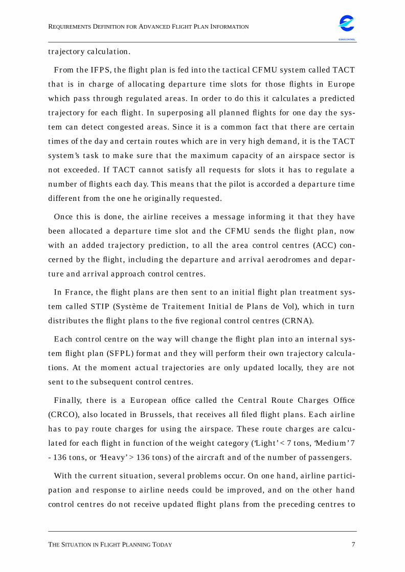
trajectory calculation.
From the IFPS, the flight plan is fed into the tactical CFMU system called TACT
that is in charge of allocating departure time slots for those flights in Europe
which pass through regulated areas. In order to do this it calculates a predicted
trajectory for each flight. In superposing all planned flights for one day the sys-
tem can detect congested areas. Since it is a common fact that there are certain
times of the day and certain routes which are in very high demand, it is the TACT
system’s task to make sure that the maximum capacity of an airspace sector is
not exceeded. If TACT cannot satisfy all requests for slots it has to regulate a
number of flights each day. This means that the pilot is accorded a departure time
different from the one he originally requested.
Once this is done, the airline receives a message informing it that they have
been allocated a departure time slot and the CFMU sends the flight plan, now
with an added trajectory prediction, to all the area control centres (ACC) con-
cerned by the flight, including the departure and arrival aerodromes and depar-
ture and arrival approach control centres.
In France, the flight plans are then sent to an initial flight plan treatment sys-
tem called STIP (Système de Traitement Initial de Plans de Vol), which in turn
distributes the flight plans to the five regional control centres (CRNA).
Each control centre on the way will change the flight plan into an internal sys-
tem flight plan (SFPL) format and they will perform their own trajectory calcula-
tions. At the moment actual trajectories are only updated locally, they are not
sent to the subsequent control centres.
Finally, there is a European office called the Central Route Charges Office
(CRCO), also located in Brussels, that receives all filed flight plans. Each airline
has to pay route charges for using the airspace. These route charges are calcu-
lated for each flight in function of the weight category (‘Light’ < 7 tons, ‘Medium’ 7
- 136 tons, or ‘Heavy’ > 136 tons) of the aircraft and of the number of passengers.
With the current situation, several problems occur. On one hand, airline partici-
pation and response to airline needs could be improved, and on the other hand
control centres do not receive updated flight plans from the preceding centres to
REQUIREMENTSDEFINITION FORADVANCED FLIGHT PLAN INFORMATION
EUROCONTROLSTRATEGY 8
EUROCONTROL
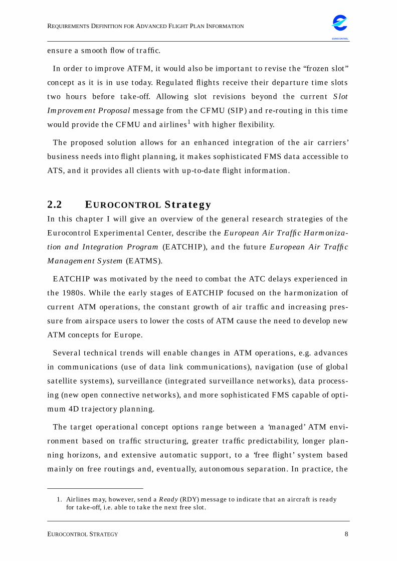
ensure a smooth flow of traffic.
In order to improve ATFM, it would also be important to revise the “frozen slot”
concept as it is in use today. Regulated flights receive their departure time slots
two hours before take-off. Allowing slot revisions beyond the current Slot
Improvement Proposal message from the CFMU (SIP) and re-routing in this time
would provide the CFMU and airlines1 with higher flexibility.
The proposed solution allows for an enhanced integration of the air carriers’
business needs into flight planning, it makes sophisticated FMS data accessible to
ATS, and it provides all clients with up-to-date flight information.
2.2 EUROCONTROL StrategyIn this chapter I will give an overview of the general research strategies of the
Eurocontrol Experimental Center, describe the European Air Traffic Harmoniza-
tion and Integration Program (EATCHIP), and the future European Air Traffic
Management System (EATMS).
EATCHIP was motivated by the need to combat the ATC delays experienced in
the 1980s. While the early stages of EATCHIP focused on the harmonization of
current ATM operations, the constant growth of air traffic and increasing pres-
sure from airspace users to lower the costs of ATM cause the need to develop new
ATM concepts for Europe.
Several technical trends will enable changes in ATM operations, e.g. advances
in communications (use of data link communications), navigation (use of global
satellite systems), surveillance (integrated surveillance networks), data process-
ing (new open connective networks), and more sophisticated FMS capable of opti-
mum 4D trajectory planning.
The target operational concept options range between a ‘managed’ ATM envi-
ronment based on traffic structuring, greater traffic predictability, longer plan-
ning horizons, and extensive automatic support, to a ‘free flight’ system based
mainly on free routings and, eventually, autonomous separation. In practice, the
1. Airlines may, however, send a Ready (RDY) message to indicate that an aircraft is readyfor take-off, i.e. able to take the next free slot.
REQUIREMENTSDEFINITION FORADVANCED FLIGHT PLAN INFORMATION
EUROCONTROLSTRATEGY 9
EUROCONTROL
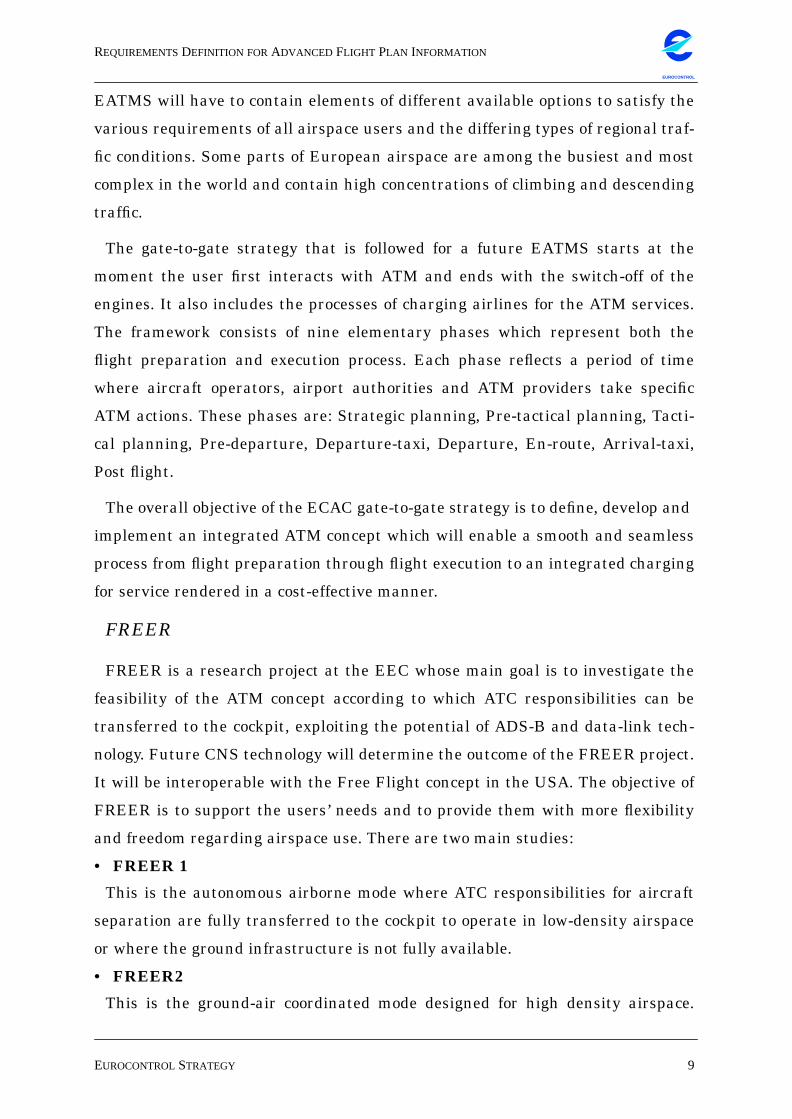
EATMS will have to contain elements of different available options to satisfy the
various requirements of all airspace users and the differing types of regional traf-
fic conditions. Some parts of European airspace are among the busiest and most
complex in the world and contain high concentrations of climbing and descending
traffic.
The gate-to-gate strategy that is followed for a future EATMS starts at the
moment the user first interacts with ATM and ends with the switch-off of the
engines. It also includes the processes of charging airlines for the ATM services.
The framework consists of nine elementary phases which represent both the
flight preparation and execution process. Each phase reflects a period of time
where aircraft operators, airport authorities and ATM providers take specific
ATM actions. These phases are: Strategic planning, Pre-tactical planning, Tacti-
cal planning, Pre-departure, Departure-taxi, Departure, En-route, Arrival-taxi,
Post flight.
The overall objective of the ECAC gate-to-gate strategy is to define, develop and
implement an integrated ATM concept which will enable a smooth and seamless
process from flight preparation through flight execution to an integrated charging
for service rendered in a cost-effective manner.
FREER
FREER is a research project at the EEC whose main goal is to investigate the
feasibility of the ATM concept according to which ATC responsibilities can be
transferred to the cockpit, exploiting the potential of ADS-B and data-link tech-
nology. Future CNS technology will determine the outcome of the FREER project.
It will be interoperable with the Free Flight concept in the USA. The objective of
FREER is to support the users’ needs and to provide them with more flexibility
and freedom regarding airspace use. There are two main studies:
• FREER 1
This is the autonomous airborne mode where ATC responsibilities for aircraft
separation are fully transferred to the cockpit to operate in low-density airspace
or where the ground infrastructure is not fully available.
• FREER2
This is the ground-air coordinated mode designed for high density airspace.

REQUIREMENTSDEFINITION FORADVANCED FLIGHT PLAN INFORMATION
EUROCONTROLSTRATEGY 10
EUROCONTROL
Here the ATC responsibilities are partially transferred to cockpit with assistance
from the ground infrastructure.
Any implementation of FREER would need all aircraft to be equipped with
ADS-B technology. A single aircraft without this system would induce an unac-
ceptable risk factor.
A possible scenario would be that the pilot hands in his preferences and has
them confirmed by ATC, at take-off and at landing he gets in contact with the
respective tower to announce his preferred departure/arrival route.
There are several constraints to the development of FREER, like the depend-
ency upon the range and the contents of ADS-B, the availability of the Cockpit
Display of Traffic Information (CDTI) standard (being developed in the USA), or
the availability of the “Extended Rules-of-the-Air” to be applied in case of conflict.
To a certain scale, these extended rules of the air may have to be developed in
FREER. In parallel to this work, there are developments in the prediction of the
“long term” trajectory of the aircraft, the complete input and output data format
of on-board Flight Management System (FMS), and the functionality of the con-
flict avoidance function in TCAS-IV.
“Free Flight” in the USA
The Federal Aviation Agency in the USA is working on the construction of a
National Airspace (NAS) Information Architecture that should comprise the proc-
esses and components required to manage NAS operational data. The primary
purpose of the NAS information architecture is to manage information efficiently
to support operational decision-making.
In 1994 US government and industry representatives started an initiative
named Free Flight, that they defined as a “safe and efficient flight operating capa-
bility under instrument flight rules (IFR) in which the operators have the free-
dom to select their path and speed in real time. Air traffic restrictions are
imposed to ensure separation, to preclude exceeding airport capacity, to prevent
unauthorized flight through special use airspace, and to ensure safety of flight.
Restrictions are limited in extent and duration to correct the identified problem.
REQUIREMENTSDEFINITION FORADVANCED FLIGHT PLAN INFORMATION
EUROCONTROLSTRATEGY 11
EUROCONTROL
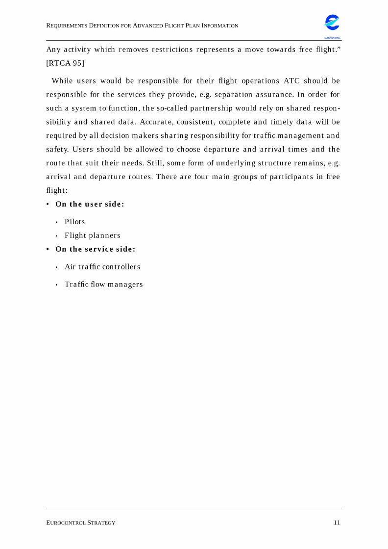
Any activity which removes restrictions represents a move towards free flight.”
[RTCA 95]
While users would be responsible for their flight operations ATC should be
responsible for the services they provide, e.g. separation assurance. In order for
such a system to function, the so-called partnership would rely on shared respon-
sibility and shared data. Accurate, consistent, complete and timely data will be
required by all decision makers sharing responsibility for traffic management and
safety. Users should be allowed to choose departure and arrival times and the
route that suit their needs. Still, some form of underlying structure remains, e.g.
arrival and departure routes. There are four main groups of participants in free
flight:
• On the user side:
• Pilots
• Flight planners
• On the service side:
• Air traffic controllers
• Traffic flow managers
REQUIREMENTSDEFINITION FORADVANCED FLIGHT PLAN INFORMATION
12
EUROCONTROL
3. BUSINESS OBJECTS:MODULAR REUSABLE STRUCTURES
In this chapter I would like to introduce the term Cooperative Business Object
(CBO) proposed in [Sim94], or business object for short.
While a business object is an object in the sense of object-oriented programming,
it has to be distinguished from an object used by a developer as a component of an
OO application. A business object is an end product whose size maps to business
items and it can be understood and manipulated by the end user. It provides a
natural way for describing application-independent concepts such as ‘customer’,
‘order’, ‘payment’ etc. It encourages a view of software that transcends tools,
applications, databases and other system concepts. A business object is a self-con-
tained deliverable that has a user interface, state, and knows how to cooperate
with other separately developed business objects to perform a desired task.
I will try to distinguish between an application, a system, a class, and a busi-
ness object:
• System: A system is a well defined arrangement of structures that mutually
influence each other. These structures can be things as well as thought meth-
ods and their results (mathematical methods, programming languages, etc.).
This arrangement is delimited from its environment by a shell. A system pro-
gram is part of an operating system and it executes service functions for appli-
cation programs [Sch91].
• Application: An application consists of application programs together with
organizational rules necessary to implement and effectively use the application
program in a specific environment (company, administration etc.). The term
application software designates all programs that are not part of the operating
system. The programs of individual application systems solve the data process-
ing tasks defined by the user’s objectives. They are often tailored for a concrete
data processing machine. Due to their individual adjustment, these programs
are generally useless to other users [Sch91].
• Class: A class is a set of objects that share a common structure and a common
behaviour. A single object is simply an instance of a class [Boo94]. A given class
REQUIREMENTSDEFINITION FORADVANCED FLIGHT PLAN INFORMATION
13
EUROCONTROL
typically has two kinds of clients: instances and subclasses. Class instances
may be transient, i.e. they cease to exist when the application is terminated.
• Business object: Although a BO is an object (a class instance), it is not lim-
ited to a single application or a single system. Usually, individual programming
language classes that form an application cannot be manipulated from outside
this application, it is usually not persistent, and it cannot be used in another
application. A BO is persistent, it has a consistent state (e.g. in a database),
and provides data consistency through a transaction mechanism. A BO is
encapsulated like any other object and it can be used in heterogeneous applica-
tions and systems through a middleware layer that provides the necessary
logic and services. In the OMG Object Management Architecture (OMA) they
are called common facilities [OHE96]. The middleware services let various BOs
communicate with each other, so that there will be no single application, but a
collection of business objects that together perform the needed tasks. For the
work of the business objects it will be irrelevant which hardware or operating
systems are installed beyond the middleware layer.
So a CBO can be defined as an application-level component that can be used in
an endless series of new combinations, independent of any single application
[Pri96].
It is not sensible to introduce new technology into a business environment with-
out any concrete necessity. If, on the other hand, the business demands new solu-
tions due to changes in the business domain, these solutions will attract the use
of new technology. In this case we would like to build an object-oriented architec-
ture and model business domain objects as a means of applying modern informa-
tion technology in ATC.
Such cooperative business objects are a new development in application struc-
turing: in theory, the CBO is a deliverable in itself, it is concurrently executable
and able to run in distributed heterogeneous computing environments. In order to
find business objects in a particular domain one may examine the external parties
the organization deals with, such as suppliers, customers, distributors etc. The
products and services that the organization sells or buys as well as the resources
that are necessary in the production process are also potential business objects
REQUIREMENTSDEFINITION FORADVANCED FLIGHT PLAN INFORMATION
14
EUROCONTROL
[YWT+95].
Reusing the objects from the user’s problem domain saves significantly on the
system design, documentation and training effort.
Properties of an object
One usually distinguishes between static and dynamic properties of an object.
While the actions that can be performed on an object belong to the static proper-
ties, the pre- and post-conditions valid for these actions belong to the dynamic
properties. The object’s attributes (static) necessitate a data validation logic
(dynamic) that will for instance refuse illegal attribute contents. Finally, the trig-
gering events from and interactions with other objects (static) can be shown in a
finite-state-machine (dynamic) to model the behaviour with an original state, the
performed action and the condition applying to the action.
Developing a cooperative business object
First one should describe an operational model of the business and identify the
business domain items; the architecture of the information system will reflect
these same objects internally and externally. So the OO information system may
be regarded as the operational model of the business. Users will find the objects in
the graphic user interface and will see the attributes and actions available under
these objects while location, storage, and retrieval remain transparent to the
user.
Definition of a cooperative business object1
• It is an object just like any object in OO programming, i.e. it is encapsulated, it
can be part of an inheritance hierarchy, it has class and instance data, and it
sends messages to other objects.
• It is a deliverable; it is the end product of the software development process,
delivered to the end-user, and it can be identified as an execution unit. A single
CBO can be executed by itself, needing only its superclasses.
• It is an independent software executable; it can be executed by itself independ-
ently from other CBOs by some build-time process. Such CBOs are loosely
1. cf. [Sim 94].
REQUIREMENTSDEFINITION FORADVANCED FLIGHT PLAN INFORMATION
15
EUROCONTROL
bound and can be packaged independently from other CBOs.
• It is language-neutral, i.e. it can be written in any language, object-oriented or
procedural. An implication of language neutrality is of course, that the lan-
guage in which a CBO is written is irrelevant to the underlying infrastructure.
• CBOs are easy to integrate; in order to integrate applications they must have a
mechanism to communicate, and a mechanism for data exchange, i.e. there
must be a common syntax (data types) and semantics (data meaning) of inter-
change. Since CBOs are objects that use messages to interact, they fulfil the
first of these two requirements. For data exchange binary interfaces are
needed, e.g. provided by the interface definition language (IDL) in CORBA.
IDLs are probably best employed where high performance is required regard-
less of other considerations such as ease of programming, or where middleware
is being built. An alternative would be a self-defining data stream, together
with sophisticated build and parse support. In using the latter, one trades per-
formance (which may be provided by an IDL) for run-time type evaluation pro-
vided by self-defining data, but there will be no recompile or relink necessary
when using another CBO for the first time, and there is run-time dynamic
binding for the data.
• CBOs are message- or event-driven; by using messages for communication
with other objects there is no difference between local and remote CBOs, syn-
chronous as well as asynchronous messages can be sent, objects can send mes-
sages to themselves or to their superclass, and all events are transformed into
a common message form by the CBO infrastructure.
• A CBO is location-transparent; i.e. the programmers need not consider if a
CBO is in the same or in a different thread, process, or system. Specifically, the
target may be written in another language, it may be running on another oper-
ating system, or reside at the other side of a wide-area network (WAN).
• It is written in code that is serially reusable, so as to avoid unnecessary block-
ing of the thread or process in which it runs.
• It is persistent; but without the use of an effective and pervasive OO database
the system has to provide for CBO persistence, where required. This can be
achieved via system-provided superclasses, and then the programmer is
handed CBO persistence by default. The system provides a persistence data-

REQUIREMENTSDEFINITION FORADVANCED FLIGHT PLAN INFORMATION
16
EUROCONTROL
base and a framework for persistence. At closing or restoring of an object, a
CBO can override superclass behaviour to handle its own saving or restoring
procedures if necessary. So CBOs are persistent unless the programmer over-
rides the persistence framework or unless subclassed from a non-persistent
class.
• It requires a software infrastructure, since the CBO infrastructure is a run-
time layer of software, together with several superclasses from which CBOs
can inherit common behaviour. In order to maintain a certain ease of program-
ming it is important to provide a set of base classes which include appropriate
frameworks.
REQUIREMENTSDEFINITION FORADVANCED FLIGHT PLAN INFORMATION
17
EUROCONTROL
4. REQUIREMENTS DEFINITION FOR A FLIGHT PLANBUSINESS OBJECT
The requirements section considers eight potential clients for an extended flight
plan; three of them are research projects of the EEC that might benefit from
enhanced flight plan information. In addition to these clients, I have described
the elements of the so-called “New Age” flight plan, a project at the FAA, to indi-
cate that the US are also putting efforts into improving data exchange between
the air carriers and ATS. Once these requirements have been listed, the second
part of this chapter contains a classification that will allow the construction of an
object that encompasses all the necessary data in an adequate structure.
The requirements listed here are divided into structure and behaviour accord-
ing to the object paradigm as described in [Boo94]. Since this thesis concentrates
on the structural aspects of an XFPL format, I will not model use cases and life
cycle behaviour. In order to understand the different users’ needs I had to identify
their requirements with the help of interviews and documentation. The require-
ments of airlines, airports, radar control, the CFMU and the CRCO have been
identified mainly through requirements documents [AP95, EAF96], the CFMU
Handbook [CFMU96], and questioning of ATC specialists at the EEC. In order to
identify the requirements of DIFODAM, BADA, and FREER with respect to flight
plan formats, I have interviewed the respective members of the projects.
By letting all relevant stakeholders participate in the design process we can
achieve more effective systems. This is why the data modelling process should not
be considered a purely technical task, but one that requires understanding of the
different users’ needs and the integration of requirements and views into one
solution. The requirements gathered here will allow the definition of relevant
attributes and member functions that an XFPL business object will contain. The
distinction between objects and attributes depends on the chosen level in the
analysis phase. In the OMT notation that I will use for modelling [RBP+91]
attributes are interpreted as data carried around by an object. Generally,
attributes are simply values uniquely associated with each object.
During analysis, attributes have a logical character and it is therefore not neces-
sary to interpret these values as specific data types. Attributes can be identified
REQUIREMENTSDEFINITION FORADVANCED FLIGHT PLAN INFORMATION
USERREQUIREMENTS 18
EUROCONTROL
by the following criteria [YWT+95]:
• Attributes represent data which has to be remembered by an object.
• Attributes do not have an independent existence, i.e. they are an integral part
of a given object.
• All attributes of a class should apply to each instance of the class.
• Implementation constructs such as linked lists should be eliminated. This
guideline will lead to the separation of “Flight Plan” and “Trajectory”.
• Also, one should beware of objects whose names are ‘window’, ‘scroll bar’,
‘menu’ etc. These may be objects that are necessary for the user interface and
are therefore related to the design phase.
4.1 User RequirementsThe different requirements may be divided into structural requirements, which
relate to the kind of data that is needed, non-behavioural requirements, which
designate the necessary quality of the data, and behavioural requirements,
which indicate the needed timely behaviour of the data. I will however concen-
trate on requirements that are relevant for the design of an XFPL format and
therefore leave out most of the data that is already communicated to ATM via the
ICAO FPL, since the proposed extended flight plan format will comprise all the
data items of the current ICAO format [ICAO85].
The gathering and classification of the user requirements is done in the perspec-
tive of finding objects, attributes and methods from three different perspectives:
the data, the functional and the behavioural perspective.
4.1.1 Airlines
A general requirement of all airlines is that they wish a more cost-efficient and
flexible ATM system capable of responding dynamically to their operational and
business needs. A gate-to-gate service as well as AOC-requested flexible and
dynamic trajectories would help to make the airlines’ operations more cost-effi-
cient. The airlines and their aircraft operations centres would benefit from new
means of communication with ATC to provide them with increased flexibility of
airspace use.
REQUIREMENTSDEFINITION FORADVANCED FLIGHT PLAN INFORMATION
USERREQUIREMENTS 19
EUROCONTROL
If it was common practice for an airline to ask ATC to re-route a flight that had
been delayed (e.g. because of the high traffic load on the departure aerodrome) the
pilot might be able to compensate for a part of the delay en-route, thus avoiding
inconvenience for the passengers. So if the airline could change the route in the
FPL and if ATC could react to the airline’s needs by recalculating the aircraft’s
trajectory and alerting the other concerned control centres, progress would have
been made.
• Structural requirements:
• The planned take-off and arrival times.
• The planned take-off and arrival aerodromes.
• A list of alternative arrival aerodromes if the first choice is not available, e.g.
due to bad weather.
• Acceptable delays for take-off and landing due to slot allocation.
• A preferred route and an alternative route if the first choice should be subject
to regulations.
• A preferred runway.
• Non-behavioural requirements:
• The communicated data should increase flight safety.
• The data format should be adaptable to technological changes.
• The FPL should be processed automatically.
• There should be an effective use of airspace.
• Behavioural requirements:
• It should be possible to use the FPL in interoperable systems.
• The deadline for filing should be closer to take-off time.
• There should be the possibility to change an FPL after initial filing.
• The flight plan should allow for an orderly flow in increasing traffic.
• The transmitted data should allow for more efficient traffic flow.
4.1.2 Airports
The requirements in this section refer to the airport technical services. Three
important parts of the air transport system interact here: the airport, the airline,
and the passenger.
REQUIREMENTSDEFINITION FORADVANCED FLIGHT PLAN INFORMATION
USERREQUIREMENTS 20
EUROCONTROL
As to the requirements of airports, it can be said that they could do more effi-
cient planning if they were aware of changes in the scheduled arrivals, i.e. if they
shared updated data with the ACCs. This way, an airport would know earlier
about impending delays and re-routings.
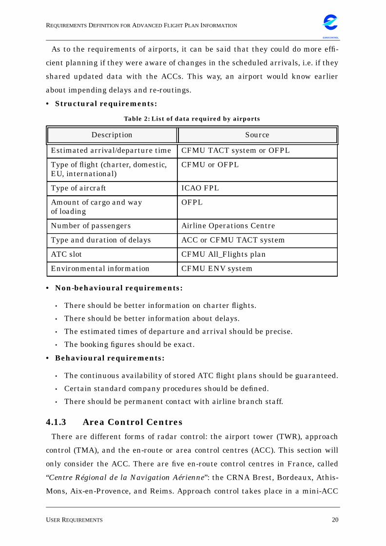
• Structural requirements:
• Non-behavioural requirements:
• There should be better information on charter flights.
• There should be better information about delays.
• The estimated times of departure and arrival should be precise.
• The booking figures should be exact.
• Behavioural requirements:
• The continuous availability of stored ATC flight plans should be guaranteed.
• Certain standard company procedures should be defined.
• There should be permanent contact with airline branch staff.
4.1.3 Area Control Centres
There are different forms of radar control: the airport tower (TWR), approach
control (TMA), and the en-route or area control centres (ACC). This section will
only consider the ACC. There are five en-route control centres in France, called
“Centre Régional de la Navigation Aérienne”: the CRNA Brest, Bordeaux, Athis-
Mons, Aix-en-Provence, and Reims. Approach control takes place in a mini-ACC
Table 2: List of data required by airports
Description Source
Estimated arrival/departure time CFMU TACT system or OFPL
Type of flight (charter, domestic,EU, international)
CFMU or OFPL
Type of aircraft ICAO FPL
Amount of cargo and wayof loading
OFPL
Number of passengers Airline Operations Centre
Type and duration of delays ACC or CFMU TACT system
ATC slot CFMU All_Flights plan
Environmental information CFMU ENV system
REQUIREMENTSDEFINITION FORADVANCED FLIGHT PLAN INFORMATION
USERREQUIREMENTS 21
EUROCONTROL
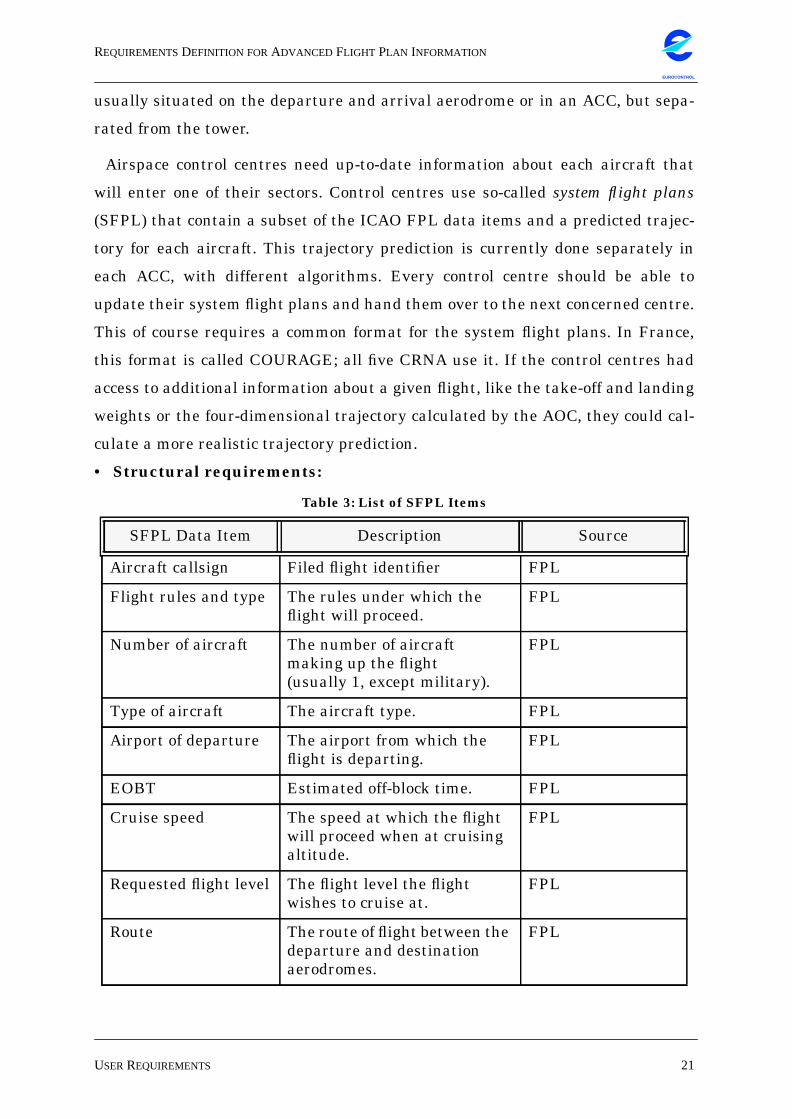
usually situated on the departure and arrival aerodrome or in an ACC, but sepa-
rated from the tower.
Airspace control centres need up-to-date information about each aircraft that
will enter one of their sectors. Control centres use so-called system flight plans
(SFPL) that contain a subset of the ICAO FPL data items and a predicted trajec-
tory for each aircraft. This trajectory prediction is currently done separately in
each ACC, with different algorithms. Every control centre should be able to
update their system flight plans and hand them over to the next concerned centre.
This of course requires a common format for the system flight plans. In France,
this format is called COURAGE; all five CRNA use it. If the control centres had
access to additional information about a given flight, like the take-off and landing
weights or the four-dimensional trajectory calculated by the AOC, they could cal-
culate a more realistic trajectory prediction.
• Structural requirements:
Table 3: List of SFPL Items
SFPL Data Item Description Source
Aircraft callsign Filed flight identifier FPL
Flight rules and type The rules under which theflight will proceed.
FPL
Number of aircraft The number of aircraftmaking up the flight(usually 1, except military).
FPL
Type of aircraft The aircraft type. FPL
Airport of departure The airport from which theflight is departing.
FPL
EOBT Estimated off-block time. FPL
Cruise speed The speed at which the flightwill proceed when at cruisingaltitude.
FPL
Requested flight level The flight level the flightwishes to cruise at.
FPL
Route The route of flight between thedeparture and destinationaerodromes.
FPL
REQUIREMENTSDEFINITION FORADVANCED FLIGHT PLAN INFORMATION
USERREQUIREMENTS 22
EUROCONTROL
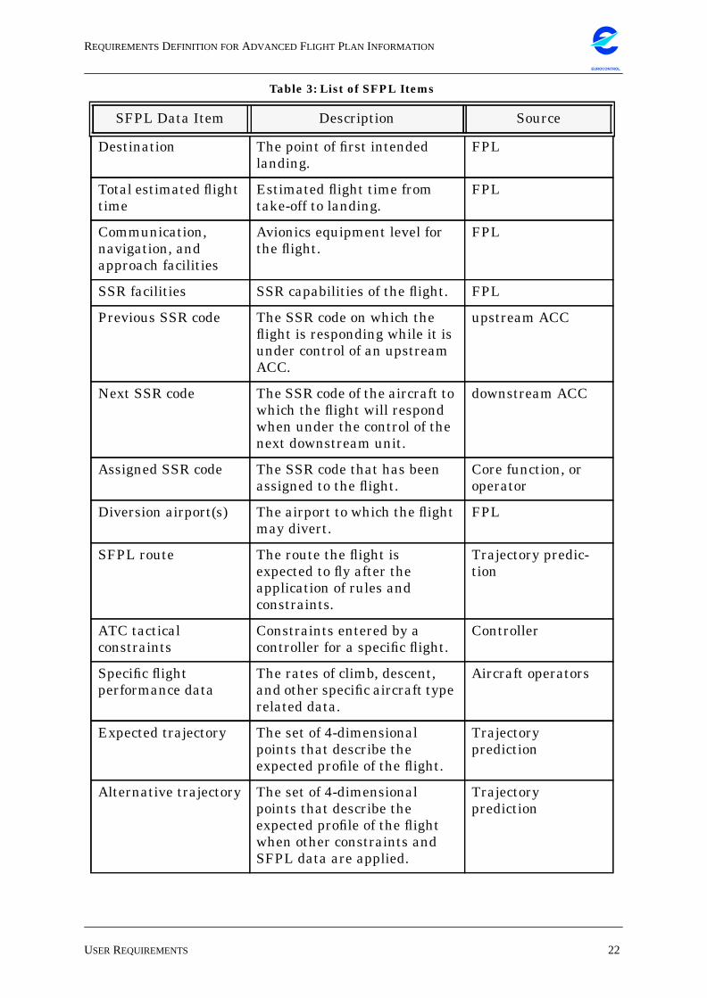
Destination The point of first intendedlanding.
FPL
Total estimated flighttime
Estimated flight time fromtake-off to landing.
FPL
Communication,navigation, andapproach facilities
Avionics equipment level forthe flight.
FPL
SSR facilities SSR capabilities of the flight. FPL
Previous SSR code The SSR code on which theflight is responding while it isunder control of an upstreamACC.
upstream ACC
Next SSR code The SSR code of the aircraft towhich the flight will respondwhen under the control of thenext downstream unit.
downstream ACC
Assigned SSR code The SSR code that has beenassigned to the flight.
Core function, oroperator
Diversion airport(s) The airport to which the flightmay divert.
FPL
SFPL route The route the flight isexpected to fly after theapplication of rules andconstraints.
Trajectory predic-tion
ATC tacticalconstraints
Constraints entered by acontroller for a specific flight.
Controller
Specific flightperformance data
The rates of climb, descent,and other specific aircraft typerelated data.
Aircraft operators
Expected trajectory The set of 4-dimensionalpoints that describe theexpected profile of the flight.
Trajectoryprediction
Alternative trajectory The set of 4-dimensionalpoints that describe theexpected profile of the flightwhen other constraints andSFPL data are applied.
Trajectoryprediction
Table 3: List of SFPL Items
SFPL Data Item Description Source
REQUIREMENTSDEFINITION FORADVANCED FLIGHT PLAN INFORMATION
USERREQUIREMENTS 23
EUROCONTROL
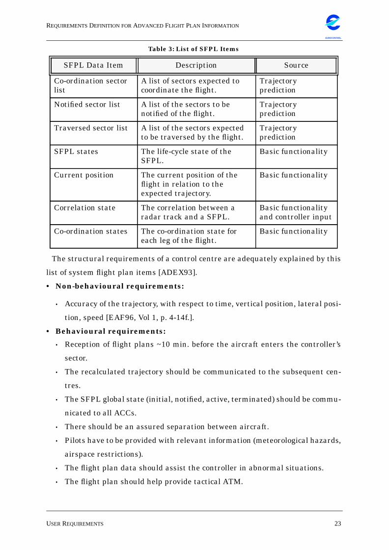
The structural requirements of a control centre are adequately explained by this
list of system flight plan items [ADEX93].
• Non-behavioural requirements:
• Accuracy of the trajectory, with respect to time, vertical position, lateral posi-
tion, speed [EAF96, Vol 1, p. 4-14f.].
• Behavioural requirements:
• Reception of flight plans ~10 min. before the aircraft enters the controller’s
sector.
• The recalculated trajectory should be communicated to the subsequent cen-
tres.
• The SFPL global state (initial, notified, active, terminated) should be commu-
nicated to all ACCs.
• There should be an assured separation between aircraft.
• Pilots have to be provided with relevant information (meteorological hazards,
airspace restrictions).
• The flight plan data should assist the controller in abnormal situations.
• The flight plan should help provide tactical ATM.
Co-ordination sectorlist
A list of sectors expected tocoordinate the flight.
Trajectoryprediction
Notified sector list A list of the sectors to benotified of the flight.
Trajectoryprediction
Traversed sector list A list of the sectors expectedto be traversed by the flight.
Trajectoryprediction
SFPL states The life-cycle state of theSFPL.
Basic functionality
Current position The current position of theflight in relation to theexpected trajectory.
Basic functionality
Correlation state The correlation between aradar track and a SFPL.
Basic functionalityand controller input
Co-ordination states The co-ordination state foreach leg of the flight.
Basic functionality
Table 3: List of SFPL Items
SFPL Data Item Description Source
REQUIREMENTSDEFINITION FORADVANCED FLIGHT PLAN INFORMATION
USERREQUIREMENTS 24
EUROCONTROL
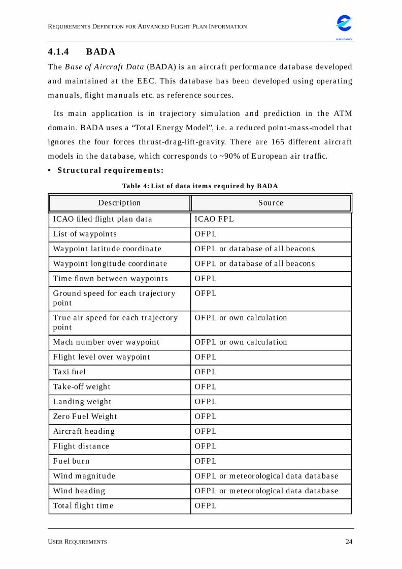
4.1.4 BADA
The Base of Aircraft Data (BADA) is an aircraft performance database developed
and maintained at the EEC. This database has been developed using operating
manuals, flight manuals etc. as reference sources.
Its main application is in trajectory simulation and prediction in the ATM
domain. BADA uses a “Total Energy Model”, i.e. a reduced point-mass-model that
ignores the four forces thrust-drag-lift-gravity. There are 165 different aircraft
models in the database, which corresponds to ~90% of European air traffic.
• Structural requirements:
Table 4: List of data items required by BADA
Description Source
ICAO filed flight plan data ICAO FPL
List of waypoints OFPL
Waypoint latitude coordinate OFPL or database of all beacons
Waypoint longitude coordinate OFPL or database of all beacons
Time flown between waypoints OFPL
Ground speed for each trajectorypoint
OFPL
True air speed for each trajectorypoint
OFPL or own calculation
Mach number over waypoint OFPL or own calculation
Flight level over waypoint OFPL
Taxi fuel OFPL
Take-off weight OFPL
Landing weight OFPL
Zero Fuel Weight OFPL
Aircraft heading OFPL
Flight distance OFPL
Fuel burn OFPL
Wind magnitude OFPL or meteorological data database
Wind heading OFPL or meteorological data database
Total flight time OFPL
REQUIREMENTSDEFINITION FORADVANCED FLIGHT PLAN INFORMATION
USERREQUIREMENTS 25
EUROCONTROL
• Non-behavioural requirements:
• The aircraft weight should be precise.
• There should be precise 4D trajectories.
• The trajectory should be calculated without consideration of expected meteo-
rological conditions.
• Behavioural requirements:
• The flight plans should be stored in a persistent form.
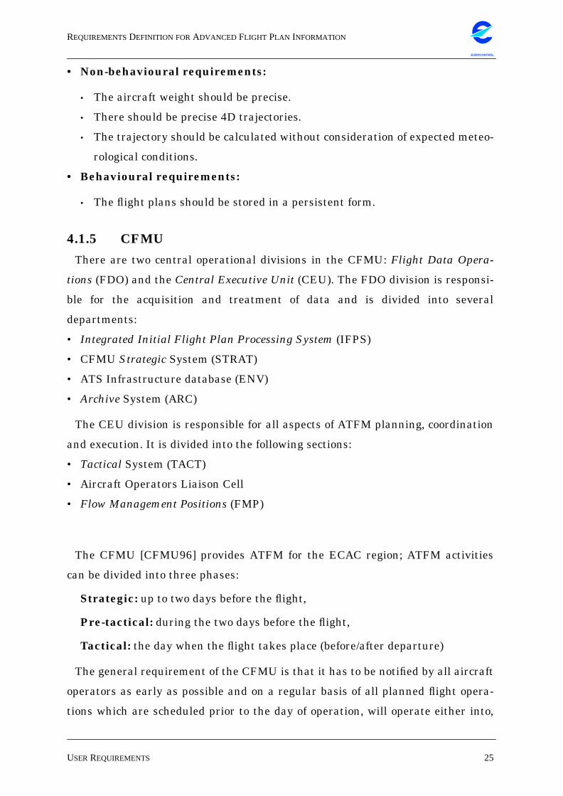
4.1.5 CFMU
There are two central operational divisions in the CFMU: Flight Data Opera-
tions (FDO) and the Central Executive Unit (CEU). The FDO division is responsi-
ble for the acquisition and treatment of data and is divided into several
departments:
• Integrated Initial Flight Plan Processing System (IFPS)
• CFMU Strategic System (STRAT)
• ATS Infrastructure database (ENV)
• Archive System (ARC)
The CEU division is responsible for all aspects of ATFM planning, coordination
and execution. It is divided into the following sections:
• Tactical System (TACT)
• Aircraft Operators Liaison Cell
• Flow Management Positions (FMP)
The CFMU [CFMU96] provides ATFM for the ECAC region; ATFM activities
can be divided into three phases:
Strategic: up to two days before the flight,
Pre-tactical: during the two days before the flight,
Tactical: the day when the flight takes place (before/after departure)
The general requirement of the CFMU is that it has to be notified by all aircraft
operators as early as possible and on a regular basis of all planned flight opera-
tions which are scheduled prior to the day of operation, will operate either into,
REQUIREMENTSDEFINITION FORADVANCED FLIGHT PLAN INFORMATION
USERREQUIREMENTS 26
EUROCONTROL
within, through, or out of the area covered by the CFMU operations, and require
ATS. The responsibility for notification of flight data lies with the aircraft opera-
tor.
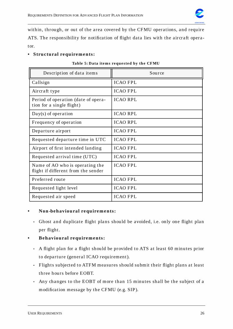
• Structural requirements:
• Non-behavioural requirements:
• Ghost and duplicate flight plans should be avoided, i.e. only one flight plan
per flight.
• Behavioural requirements:
• A flight plan for a flight should be provided to ATS at least 60 minutes prior
to departure (general ICAO requirement).
• Flights subjected to ATFM measures should submit their flight plans at least
three hours before EOBT.
• Any changes to the EOBT of more than 15 minutes shall be the subject of a
modification message by the CFMU (e.g. SIP).
Table 5: Data items requested by the CFMU
Description of data items Source
Callsign ICAO FPL
Aircraft type ICAO FPL
Period of operation (date of opera-tion for a single flight)
ICAO RPL
Day(s) of operation ICAO RPL
Frequency of operation ICAO RPL
Departure airport ICAO FPL
Requested departure time in UTC ICAO FPL
Airport of first intended landing ICAO FPL
Requested arrival time (UTC) ICAO FPL
Name of AO who is operating theflight if different from the sender
ICAO FPL
Preferred route ICAO FPL
Requested light level ICAO FPL
Requested air speed ICAO FPL
REQUIREMENTSDEFINITION FORADVANCED FLIGHT PLAN INFORMATION
USERREQUIREMENTS 27
EUROCONTROL
• A flight plan which replaces a RPL or a previously filed flight plan designated
as a replacement flight plan, shall be filed at least 30 minutes before EOBT.
• The flight plan originator should cancel a flight plan as soon as he/she knows
that the flight is not going to take place.
• The flight plan originator should cancel an existing FPL before filing a re-
placement FPL for the same flight.
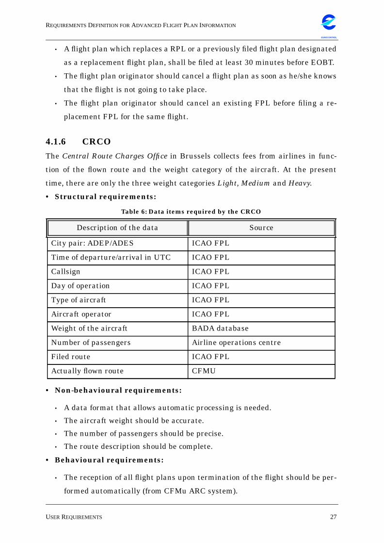
4.1.6 CRCO
The Central Route Charges Office in Brussels collects fees from airlines in func-
tion of the flown route and the weight category of the aircraft. At the present
time, there are only the three weight categories Light, Medium and Heavy.
• Structural requirements:
• Non-behavioural requirements:
• A data format that allows automatic processing is needed.
• The aircraft weight should be accurate.
• The number of passengers should be precise.
• The route description should be complete.
• Behavioural requirements:
• The reception of all flight plans upon termination of the flight should be per-
formed automatically (from CFMu ARC system).
Table 6: Data items required by the CRCO
Description of the data Source
City pair: ADEP/ADES ICAO FPL
Time of departure/arrival in UTC ICAO FPL
Callsign ICAO FPL
Day of operation ICAO FPL
Type of aircraft ICAO FPL
Aircraft operator ICAO FPL
Weight of the aircraft BADA database
Number of passengers Airline operations centre
Filed route ICAO FPL
Actually flown route CFMU
REQUIREMENTSDEFINITION FORADVANCED FLIGHT PLAN INFORMATION
USERREQUIREMENTS 28
EUROCONTROL
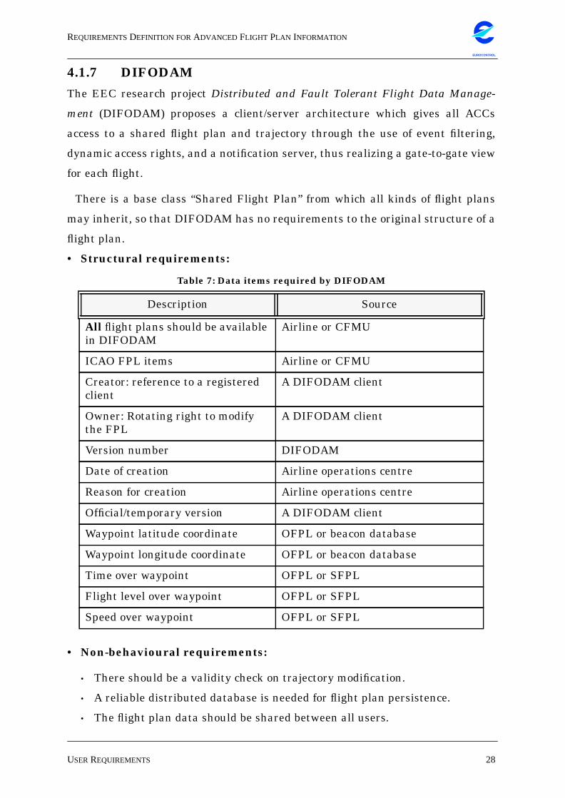
4.1.7 DIFODAM
The EEC research project Distributed and Fault Tolerant Flight Data Manage-
ment (DIFODAM) proposes a client/server architecture which gives all ACCs
access to a shared flight plan and trajectory through the use of event filtering,
dynamic access rights, and a notification server, thus realizing a gate-to-gate view
for each flight.
There is a base class “Shared Flight Plan” from which all kinds of flight plans
may inherit, so that DIFODAM has no requirements to the original structure of a
flight plan.
• Structural requirements:
• Non-behavioural requirements:
• There should be a validity check on trajectory modification.
• A reliable distributed database is needed for flight plan persistence.
• The flight plan data should be shared between all users.
Table 7: Data items required by DIFODAM
Description Source
All flight plans should be availablein DIFODAM
Airline or CFMU
ICAO FPL items Airline or CFMU
Creator: reference to a registeredclient
A DIFODAM client
Owner: Rotating right to modifythe FPL
A DIFODAM client
Version number DIFODAM
Date of creation Airline operations centre
Reason for creation Airline operations centre
Official/temporary version A DIFODAM client
Waypoint latitude coordinate OFPL or beacon database
Waypoint longitude coordinate OFPL or beacon database
Time over waypoint OFPL or SFPL
Flight level over waypoint OFPL or SFPL
Speed over waypoint OFPL or SFPL
REQUIREMENTSDEFINITION FORADVANCED FLIGHT PLAN INFORMATION
USERREQUIREMENTS 29
EUROCONTROL
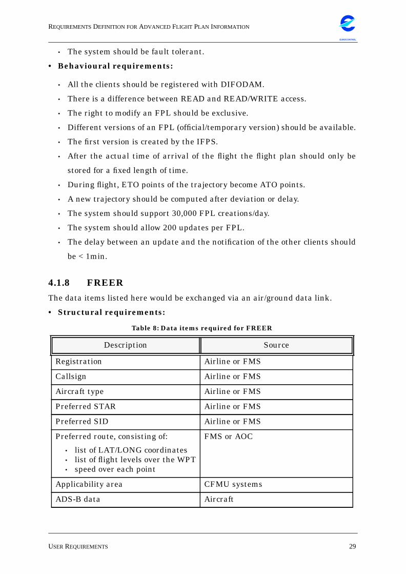
• The system should be fault tolerant.
• Behavioural requirements:
• All the clients should be registered with DIFODAM.
• There is a difference between READ and READ/WRITE access.
• The right to modify an FPL should be exclusive.
• Different versions of an FPL (official/temporary version) should be available.
• The first version is created by the IFPS.
• After the actual time of arrival of the flight the flight plan should only be
stored for a fixed length of time.
• During flight, ETO points of the trajectory become ATO points.
• A new trajectory should be computed after deviation or delay.
• The system should support 30,000 FPL creations/day.
• The system should allow 200 updates per FPL.
• The delay between an update and the notification of the other clients should
be < 1min.
4.1.8 FREER
The data items listed here would be exchanged via an air/ground data link.
• Structural requirements:
Table 8: Data items required for FREER
Description Source
Registration Airline or FMS
Callsign Airline or FMS
Aircraft type Airline or FMS
Preferred STAR Airline or FMS
Preferred SID Airline or FMS
Preferred route, consisting of:
• list of LAT/LONG coordinates• list of flight levels over the WPT• speed over each point
FMS or AOC
Applicability area CFMU systems
ADS-B data Aircraft
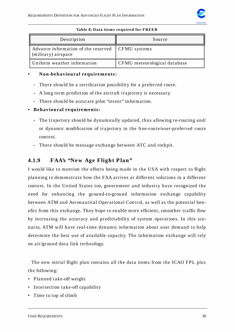
REQUIREMENTSDEFINITION FORADVANCED FLIGHT PLAN INFORMATION
USERREQUIREMENTS 30
EUROCONTROL
• Non-behavioural requirements:
• There should be a certification possibility for a preferred route.
• A long term prediction of the aircraft trajectory is necessary.
• There should be accurate pilot “intent” information.
• Behavioural requirements:
• The trajectory should be dynamically updated, thus allowing re-routing and/
or dynamic modification of trajectory in the free-route/user-preferred route
context.
• There should be message exchange between ATC and cockpit.
4.1.9 FAA’s “New Age Flight Plan”
I would like to mention the efforts being made in the USA with respect to flight
planning to demonstrate how the FAA arrives at different solutions in a different
context. In the United States too, government and industry have recognized the
need for enhancing the ground-to-ground information exchange capability
between ATM and Aeronautical Operational Control, as well as the potential ben-
efits from this exchange. They hope to enable more efficient, smoother traffic flow
by increasing the accuracy and predictability of system operations. In this sce-
nario, ATM will have real-time dynamic information about user demand to help
determine the best use of available capacity. The information exchange will rely
on air/ground data link technology.
The new initial flight plan contains all the data items from the ICAO FPL plus
the following:
• Planned take-off weight
• Intersection take-off capability
• Time to top of climb
Advance information of the reserved(military) airspace
CFMU systems
Uniform weather information CFMU meteorological database
Table 8: Data items required for FREER
Description Source
REQUIREMENTSDEFINITION FORADVANCED FLIGHT PLAN INFORMATION
USERREQUIREMENTS 31
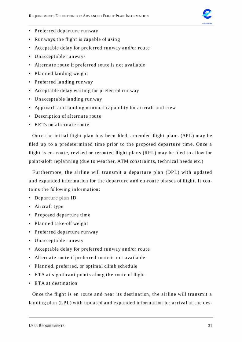
EUROCONTROL
• Preferred departure runway
• Runways the flight is capable of using
• Acceptable delay for preferred runway and/or route
• Unacceptable runways
• Alternate route if preferred route is not available
• Planned landing weight
• Preferred landing runway
• Acceptable delay waiting for preferred runway
• Unacceptable landing runway
• Approach and landing minimal capability for aircraft and crew
• Description of alternate route
• EETs on alternate route
Once the initial flight plan has been filed, amended flight plans (APL) may be
filed up to a predetermined time prior to the proposed departure time. Once a
flight is en- route, revised or rerouted flight plans (RPL) may be filed to allow for
point-aloft replanning (due to weather, ATM constraints, technical needs etc.)
Furthermore, the airline will transmit a departure plan (DPL) with updated
and expanded information for the departure and en-route phases of flight. It con-
tains the following information:
• Departure plan ID
• Aircraft type
• Proposed departure time
• Planned take-off weight
• Preferred departure runway
• Unacceptable runway
• Acceptable delay for preferred runway and/or route
• Alternate route if preferred route is not available
• Planned, preferred, or optimal climb schedule
• ETA at significant points along the route of flight
• ETA at destination
Once the flight is en route and near its destination, the airline will transmit a
landing plan (LPL) with updated and expanded information for arrival at the des-
REQUIREMENTSDEFINITION FORADVANCED FLIGHT PLAN INFORMATION
CLASSIFICATION OFUSERREQUIREMENTS 32
EUROCONTROL
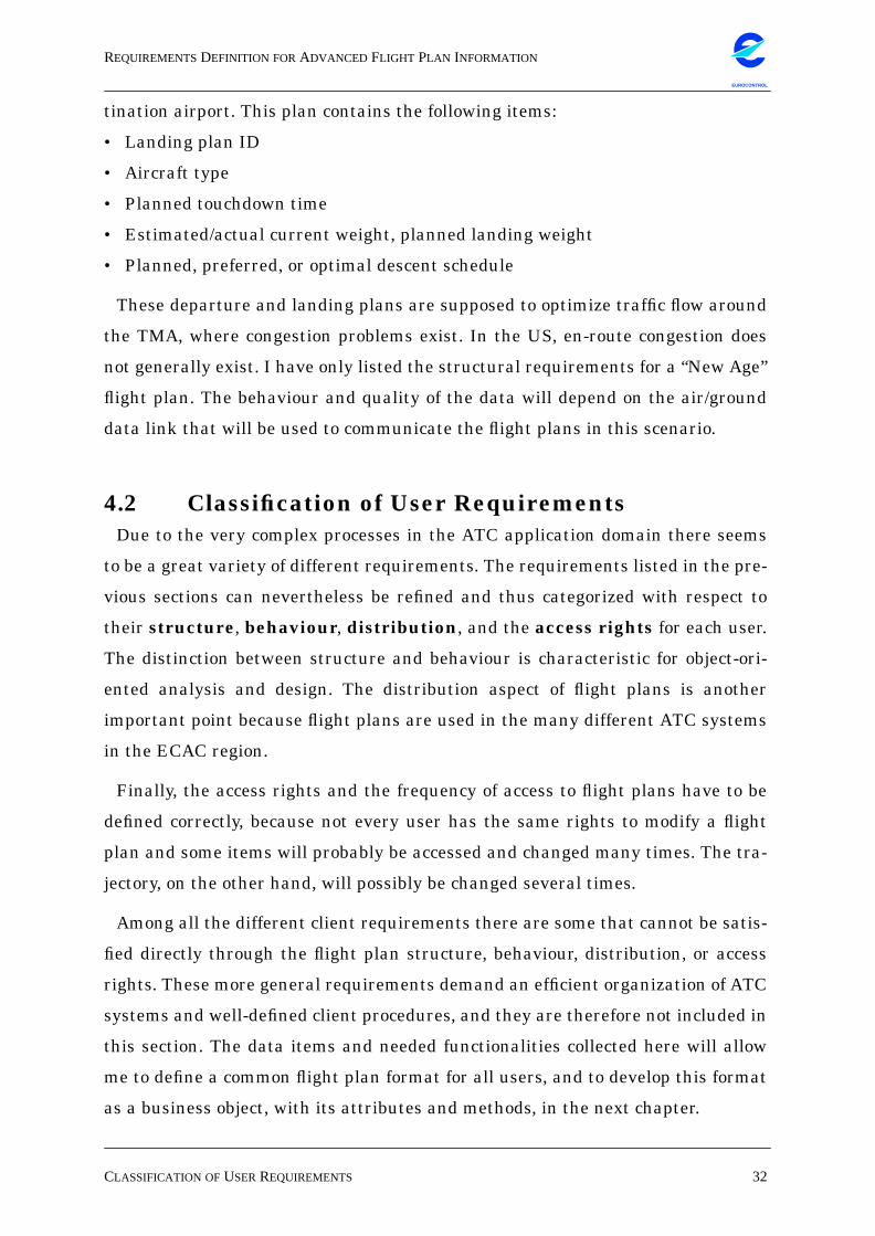
tination airport. This plan contains the following items:
• Landing plan ID
• Aircraft type
• Planned touchdown time
• Estimated/actual current weight, planned landing weight
• Planned, preferred, or optimal descent schedule
These departure and landing plans are supposed to optimize traffic flow around
the TMA, where congestion problems exist. In the US, en-route congestion does
not generally exist. I have only listed the structural requirements for a “New Age”
flight plan. The behaviour and quality of the data will depend on the air/ground
data link that will be used to communicate the flight plans in this scenario.
4.2 Classification of User RequirementsDue to the very complex processes in the ATC application domain there seems
to be a great variety of different requirements. The requirements listed in the pre-
vious sections can nevertheless be refined and thus categorized with respect to
their structure, behaviour, distribution, and the access rights for each user.
The distinction between structure and behaviour is characteristic for object-ori-
ented analysis and design. The distribution aspect of flight plans is another
important point because flight plans are used in the many different ATC systems
in the ECAC region.
Finally, the access rights and the frequency of access to flight plans have to be
defined correctly, because not every user has the same rights to modify a flight
plan and some items will probably be accessed and changed many times. The tra-
jectory, on the other hand, will possibly be changed several times.
Among all the different client requirements there are some that cannot be satis-
fied directly through the flight plan structure, behaviour, distribution, or access
rights. These more general requirements demand an efficient organization of ATC
systems and well-defined client procedures, and they are therefore not included in
this section. The data items and needed functionalities collected here will allow
me to define a common flight plan format for all users, and to develop this format
as a business object, with its attributes and methods, in the next chapter.
REQUIREMENTSDEFINITION FORADVANCED FLIGHT PLAN INFORMATION
CLASSIFICATION OFUSERREQUIREMENTS 33
EUROCONTROL
• Structure of a flight plan
In order to identify a classified set of structural requirements we can follow a
certain procedure: The different users often require the same structural data, e.g.
the aircraft callsign. Thus repeating requirements could be eliminated as a first
step. Then those requirements that need not be included in the flight plan infor-
mation should be discarded, e.g. data that will only be available in a future sce-
nario (FREER), data that belongs to internal client systems (sector names in an
ACC), or redundant data that can be calculated when needed (machnumber -
speed in knots). Finally, it is possible to group requirements that have a strong
semantic relation, and only give different values for the same unit, such as esti-
mated and actual times for departure and arrival.
The structural requirements in the table below refer to data that may be either
unchangeable after filing, and data that may change one or many times after fil-
ing or as the flight progresses. It is obvious that certain data elements cannot be
changed after filing, such as the departure airport. On the other hand it is an
important requirement that certain other data should be updated after filing,
such as the trajectory and meteorological information.
The table below lists different requirements that refer to the departure and
arrival times, the estimated and actual total elapsed times. and to the first
requested and alternative arrival aerodromes. These required data as such
should not be changed after filing, but it is possible to unify them into one single
data field. Instead of indicating static information such as “planned take-off time”
and “allocated take-off slot time” etc. it is possible to simply indicate the “take-off
time”. This take-off time would at first be the take-off time as planned by the air-
line. Then the calculated take-off time by the CFMU would replace this initially
indicated time, and finally the actual take-off time may replace the slot time if the
two are not the same. Every change in the exact semantics of the attribute “take-
off time” should be tracable through the version number and the state of the flight
plan object.
The same could be done for the “estimated total elapsed time” and the “actual
total elapsed time”. It would be sufficient to indicate a “total elapsed time”, that
may be updated if delays occur.
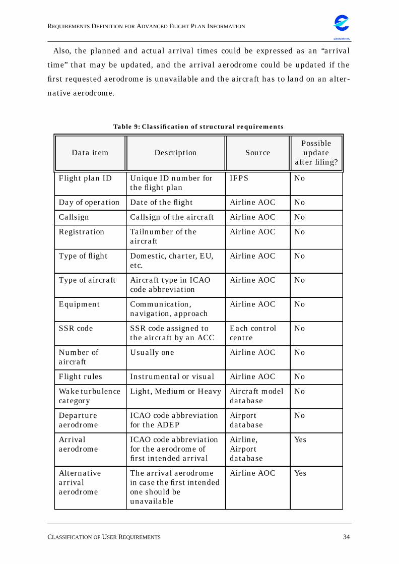
REQUIREMENTSDEFINITION FORADVANCED FLIGHT PLAN INFORMATION
CLASSIFICATION OFUSERREQUIREMENTS 34
EUROCONTROL
Also, the planned and actual arrival times could be expressed as an “arrival
time” that may be updated, and the arrival aerodrome could be updated if the
first requested aerodrome is unavailable and the aircraft has to land on an alter-
native aerodrome.
Table 9: Classification of structural requirements
Data item Description SourcePossibleupdate
after filing?
Flight plan ID Unique ID number forthe flight plan
IFPS No
Day of operation Date of the flight Airline AOC No
Callsign Callsign of the aircraft Airline AOC No
Registration Tailnumber of theaircraft
Airline AOC No
Type of flight Domestic, charter, EU,etc.
Airline AOC No
Type of aircraft Aircraft type in ICAOcode abbreviation
Airline AOC No
Equipment Communication,navigation, approach
Airline AOC No
SSR code SSR code assigned tothe aircraft by an ACC
Each controlcentre
No
Number ofaircraft
Usually one Airline AOC No
Flight rules Instrumental or visual Airline AOC No
Wake turbulencecategory
Light, Medium or Heavy Aircraft modeldatabase
No
Departureaerodrome
ICAO code abbreviationfor the ADEP
Airportdatabase
No
Arrivalaerodrome
ICAO code abbreviationfor the aerodrome offirst intended arrival
Airline,Airportdatabase
Yes
Alternativearrivalaerodrome
The arrival aerodromein case the first intendedone should beunavailable
Airline AOC Yes
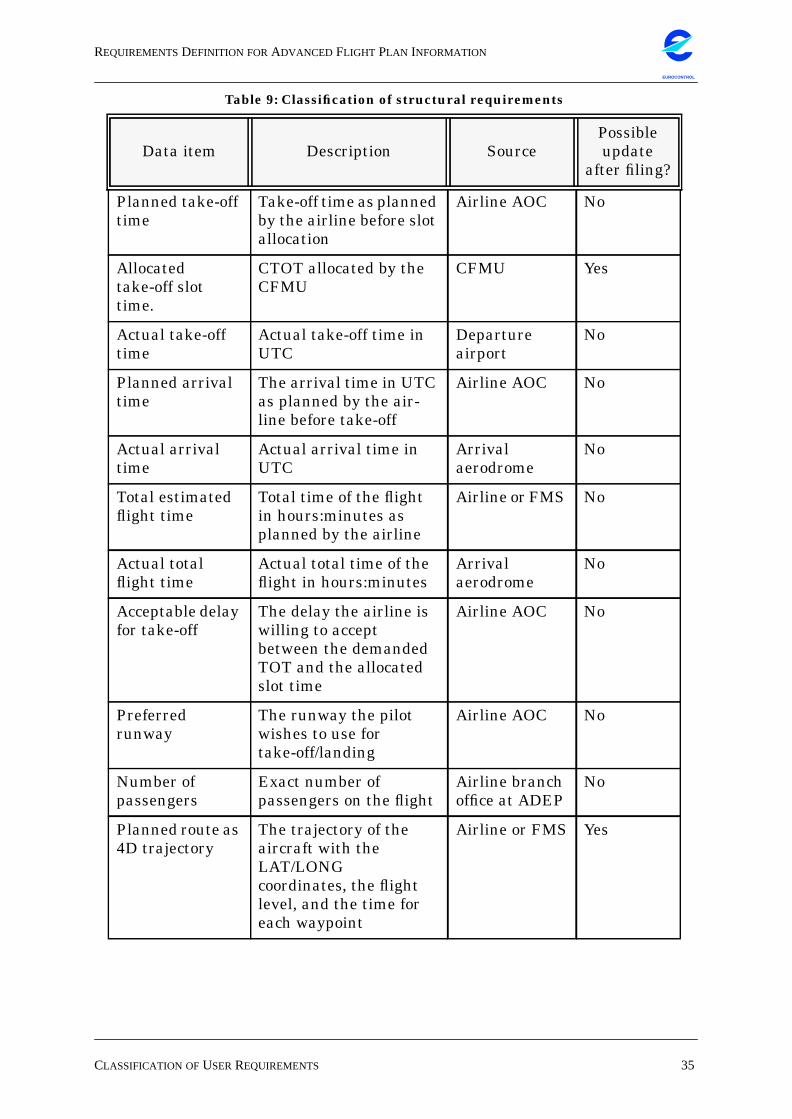
REQUIREMENTSDEFINITION FORADVANCED FLIGHT PLAN INFORMATION
CLASSIFICATION OFUSERREQUIREMENTS 35
EUROCONTROL
Planned take-offtime
Take-off time as plannedby the airline before slotallocation
Airline AOC No
Allocatedtake-off slottime.
CTOT allocated by theCFMU
CFMU Yes
Actual take-offtime
Actual take-off time inUTC
Departureairport
No
Planned arrivaltime
The arrival time in UTCas planned by the air-line before take-off
Airline AOC No
Actual arrivaltime
Actual arrival time inUTC
Arrivalaerodrome
No
Total estimatedflight time
Total time of the flightin hours:minutes asplanned by the airline
Airline or FMS No
Actual totalflight time
Actual total time of theflight in hours:minutes
Arrivalaerodrome
No
Acceptable delayfor take-off
The delay the airline iswilling to acceptbetween the demandedTOT and the allocatedslot time
Airline AOC No
Preferredrunway
The runway the pilotwishes to use fortake-off/landing
Airline AOC No
Number ofpassengers
Exact number ofpassengers on the flight
Airline branchoffice at ADEP
No
Planned route as4D trajectory
The trajectory of theaircraft with theLAT/LONGcoordinates, the flightlevel, and the time foreach waypoint
Airline or FMS Yes
Table 9: Classification of structural requirements
Data item Description SourcePossibleupdate
after filing?
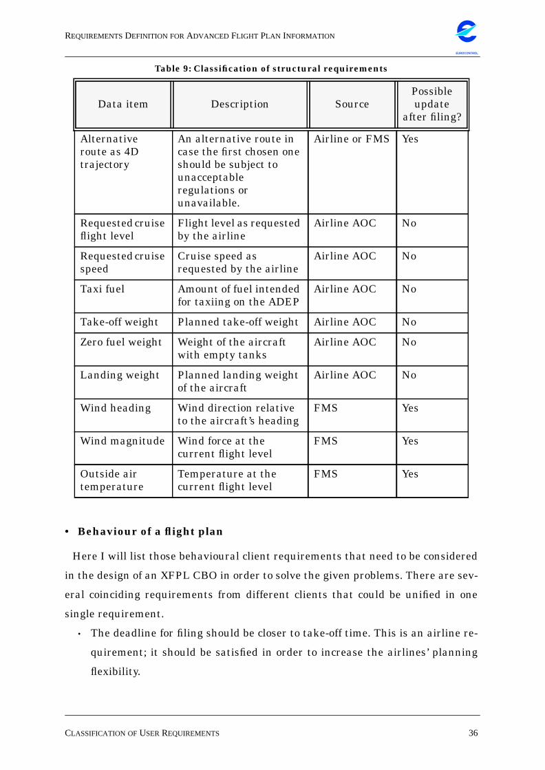
REQUIREMENTSDEFINITION FORADVANCED FLIGHT PLAN INFORMATION
CLASSIFICATION OFUSERREQUIREMENTS 36
EUROCONTROL
• Behaviour of a flight plan
Here I will list those behavioural client requirements that need to be considered
in the design of an XFPL CBO in order to solve the given problems. There are sev-
eral coinciding requirements from different clients that could be unified in one
single requirement.
• The deadline for filing should be closer to take-off time. This is an airline re-
quirement; it should be satisfied in order to increase the airlines’ planning
flexibility.
Alternativeroute as 4Dtrajectory
An alternative route incase the first chosen oneshould be subject tounacceptableregulations orunavailable.
Airline or FMS Yes
Requested cruiseflight level
Flight level as requestedby the airline
Airline AOC No
Requested cruisespeed
Cruise speed asrequested by the airline
Airline AOC No
Taxi fuel Amount of fuel intendedfor taxiing on the ADEP
Airline AOC No
Take-off weight Planned take-off weight Airline AOC No
Zero fuel weight Weight of the aircraftwith empty tanks
Airline AOC No
Landing weight Planned landing weightof the aircraft
Airline AOC No
Wind heading Wind direction relativeto the aircraft’s heading
FMS Yes
Wind magnitude Wind force at thecurrent flight level
FMS Yes
Outside airtemperature
Temperature at thecurrent flight level
FMS Yes
Table 9: Classification of structural requirements
Data item Description SourcePossibleupdate
after filing?
REQUIREMENTSDEFINITION FORADVANCED FLIGHT PLAN INFORMATION
CLASSIFICATION OFUSERREQUIREMENTS 37
EUROCONTROL
• It should be possible to change the filed flight plan. This is another airline re-
quirement with the same goal as the one mentioned above.
• The flight plan should be continuously available and persistent. This is a gen-
eral requirement from all users, and it is therefore necessary to provide a
mechanism for permanent flight plan access and persistence.
• The flight plan should have global states throughout its life cycle. This is re-
quired by the ACCs and by the CFMU. By implementing well-defined life cy-
cle behaviour we can assure access control to each flight plan.
• The flight plan originator should cancel a flight plan as soon as he/she knows
that the flight is not going to take place. This is a CFMU requirement. By as-
suring that each flight is represented by exactly one flight plan, we can avoid
so-called “ghost” flight plans that interfere with ATFM performance.
• The flight plan originator should cancel an existing flight plan before filing a
replacement flight plan for the same flight. This is another CFMU require-
ment that is closely related to the preceding one. In addition to the cancelling
mechanism mentioned above, this requirement asks for an explicit replace-
ment mechanism. This behaviour will allow exactly one flight plan per flight
at a given time.
• There should be the possibility for dynamic trajectory updates after regula-
tion or delay. This is required by the ACCs and by FREER. It is important to
fulfil this requirement because updated trajectories are essential in enhanc-
ing the controllers’ work.
• During the flight, the planned trajectory points should be updated and
marked as realized trajectory points. This is a DIFODAM requirement that
will allow every user to observe flight progress.
There are also several requirements that have not been selected for the required
flight plan behaviour. There are ACC requirements that do not concern flight plan
behaviour as such; those requirements have to be satisfied by handover proce-
dures. Furthermore, the requirement that the CRCO should receive all flight
plans automatically upon termination of each flight is a function that has to be
implemented within the CRCO system. The FREER requirement that there
should be a message exchange between cockpit and ATC refers to data-link tech-
nology and not to the actual flight plan format. Finally, there are DIFODAM
REQUIREMENTSDEFINITION FORADVANCED FLIGHT PLAN INFORMATION
CLASSIFICATION OFUSERREQUIREMENTS 38
EUROCONTROL
requirements that rather concern system performance (FPL/day).
• Access rights for the users
The requirements listed here have been selected from those clients’ behavioural
requirements that relate to access control for flight plans. All the requirements in
this section originate from DIFODAM requirements, since DIFODAM proposes
an architecture with well-defined client roles and rights.
• Each flight plan has one creator. This is a DIFODAM requirement that refers
to the flight plan’s life cycle behaviour - only a pilot or an AOC may create a
flight plan.
• The creator should have the possibility to modify a flight plan after filing and
send a new one. This DIFODAM requirement extends the “modify flight plan”
requirement from the behaviour section. It limits the right to modify and re-
vise a flight plan upon filing to the creator.
• Each flight plan has a current owner who holds the access token that allows
him/her to modify the flight plan. This is another DIFODAM requirement
that asks for the implementation of a state behaviour with controlled read/
write access.
• Each flight plan has a version number that will be updated. This is also a DI-
FODAM requirement. Recording the different versions of a flight plan is use-
ful in combination with controlled state behaviour.
• The right to modify a flight plan is exclusive. This is an essential requirement
from DIFODAM. It requires an access token mechanism. This would allow for
consistent client views because any modification by a client would first result
in an update of the database model and consequently in a client view update
before the access token is passed on to the next client.
• Depending on the user, there should be either READ or READ/WRITE access.
This DIFODAM requirement is important because it requires the definition
of different client roles and consequently the implementation of individual
client rights.
• Access to a flight plan should be possible at any time during the flight plan’s
existence. This is another DIFODAM requirement that requires particular
infrastructure services.
REQUIREMENTSDEFINITION FORADVANCED FLIGHT PLAN INFORMATION
CLASSIFICATION OFUSERREQUIREMENTS 39
EUROCONTROL
• All users should have access to changes in a flight plan immediately after
these changes have been made, which could be provided via an event notifi-
cation service. One last DIFODAM requirement, this one also refers to an in-
frastructure capability.
• Flight plan distribution
• There should be different interfaces for different users who have their own
specific needs. This is a general requirement from all clients, and it is impor-
tant to respect this requirement for the realization of a common format with
individual client views.
• The flight plan should be stored in a persistent form at one or more locations
that are transparent to the user. This requirement from DIFODAM extends
the more general requirement for persistence. The transparent access to
flight plans is another service that has to be provided by the infrastructure.
• It should be possible to use the flight plan in interoperable systems. This re-
quirement comes from the airlines, but it is also a general requirement, that
results from the fact that there are many different heterogeneous systems in
the ECAC region using flight plans.
REQUIREMENTSDEFINITION FORADVANCED FLIGHT PLAN INFORMATION
40
EUROCONTROL
5. DEVELOPMENT OF AN XFPL BUSINESS OBJECTThis chapter contains the definition of the data structure of a proposed extended
flight plan format that is based on the existing ICAO format. This XFPL will be
modelled as a CBO and I will propose a possible infrastructure for the CBO. In
the last part of this chapter I will map the object model to the relational data
model of the SOFT project database.
There are several reasons for modelling the XFPL as an object. Object technol-
ogy is an innovative computing paradigm and its principles encourage the con-
struction of modular and adaptable systems. A CBO has all the advantages of
object orientation: possible re-use, incremental development through inheritance,
encapsulation of data, and reduction of the scope of changes [Boo94]. Also, it cor-
responds to the idea of ‘networked objects’. The integration of all the relevant user
requirements into one object will allow all concerned users to view and manipu-
late the same object and it would eliminate the current problems that arise from
the different formats used by the flight plan clients. The following approach for
finding objects from the structural perspective has been suggested by Yourdan
[YWT+95]: persons, places, things, events, concepts, and other systems are all
candidate objects which can be captured in a class diagram. One could imagine
CBOs other than the XFPL for the ATC domain, such as ‘Aircraft’, ‘Airport’, ‘Sec-
tor’ etc.
Candidate business objects
All the concepts listed above are candidate business objects for the ATC domain.
It would also have been possible to create a ‘Trajectory’ business object that could
be used by the CFMU, approach control, and by the en-route centres. This ‘Trajec-
tory’ object could be modelled as an aggregation of the FMS 4D-trajectory and of
some basic data from the ICAO FPL. In a future scenario with air/ground data
link technology, such an object could be used for cockpit-controller interaction.
Although the four-dimensional trajectory is an important product for ATC, I have
not considered it as the essential product. There are less clients for a ‘Trajectory’
business object (CFMU, approach control and ACC) than for a ‘Flight Plan’ busi-
ness object (the eight clients listed in chapter 4). The aircraft trajectory is of cen-
tral interest for ATFM and while the flight is in the air. During all the other
REQUIREMENTSDEFINITION FORADVANCED FLIGHT PLAN INFORMATION
DEFINITION OF AN XFPL FORMAT 41
EUROCONTROL
phases, especially from a gate-to-gate viewpoint, the trajectory is not of primary
interest.
I have however chosen to extend the existing flight plan format and to integrate
the trajectory into it. The main reason for not separating ‘Trajectory’ and ‘flight
Plan’ is that there is always a one-to-one relation between a flight performed by
an aircraft and the aircraft’s trajectory. Both are strongly related and this seman-
tic relation has led to the design decision presented here. This solution admits
more clients for the CBO and therefore it can be of greater use to all participants.
Those clients who are primarily interested in the trajectory are free to define
their own particular view on the XFPL object, with the trajectory as the central
element.
For the object modelling part I use the Object Modelling Technique (OMT). Of
the three models for a complete system description [RBP+91] I will only use the
object model, because the emphasis of this paper lies on the structural aspects of
the flight plan. I have restricted the number of methods shown in the diagrams to
those definitely needed.
I will limit the area of discourse to those functions and parts of ATS that are
actually involved in creating, using, and changing flight plans. Now it is not easy
to define the exact semantics of the term “flight plan” because to each succeeding
user of a flight plan (each user has his own flight plan format) the term has its
own meaning. The airline pilot who creates a flight plan to be filed in the ICAO
format expresses his flight intentions in it. Then the CFMU TACT system will
regard it as a requested flight route that has to be arranged in an optimized man-
ner in order to make the best use of the available airspace. The controller in a
radar centre will use the flight plan as a flight history and as a working aid to
perform his tasks. So a flight plan has many different roles during its existence.
5.1 Definition of an XFPL FormatBased on the classification of the user requirements in the previous chapter it is
now possible to create an XFPL object containing the following attributes and
methods. All attributes have to be declared as ‘private ’ to avoid access from an
unauthorized part of the system.
REQUIREMENTSDEFINITION FORADVANCED FLIGHT PLAN INFORMATION
DEFINITION OF AN XFPL FORMAT 42
EUROCONTROL
From the ICAO filed flight plan format the XFPL will contain the following ele-
ments:
• Message type: Today, there are only two types of flight plans: the filed flight
plan (FPL) or repetitive flight plan (RPL).
• Callsign: The callsign1 of the aircraft in ICAO code abbreviation.
• Flight rules: Indicates if the flight is under visual or under instrumental flight
rules.
• Type of flight: Indicates if the flight is scheduled or non-scheduled.
• Number: The number of aircraft; usually one.
• Type of aircraft: The aircraft type in ICAO code.
• Wake turbulence category: The aircraft’s weight fits in one of three categories,
Light, Medium, or Heavy.
• Equipment: The aircraft’s communication, navigation, and approach aid equip-
ment.
• Departure aerodrome: The departure aerodrome in ICAO code name.
• Departure time: The planned departure time. This time may be modified if dif-
ferent from the actual departure time.
• Cruising speed: The cruising speed demanded by the pilot.
• Cruising level: The cruising level demanded by the pilot.
• Destination aerodrome: The planned destination aerodrome.
• Alternative destination aerodrome: An alternative aerodrome if the first choice
is unavailable.
• 2nd alternative destination aerodrome: A second alternative aerodrome if the
first two aerodromes are unavailable.
• Registration: The aircraft registration2.
• Total EET: The total planned flight time.
• Passengers: The number of passengers is a supplementary piece of information
in the ICAO flight plan, but it is not currently transmitted in the FPL message.
This data is currently used and it will be necessary to include it in the proposed
XFPL format3.
1. In the ICAO filed flight plan this field is called “Aircraft ID”.2. Often called the “tailnumber” of the aircraft.3. See also: chapter 4.1.9 The “New Age” Flight Plan.
REQUIREMENTSDEFINITION FORADVANCED FLIGHT PLAN INFORMATION
DEFINITION OF AN XFPL FORMAT 43
EUROCONTROL
The planned route from the ICAO FPL will be replaced by a precise 4D route
calculated by the AOC before take-off. The AOC that has access to all the OFPL
information will supply the following data elements:
• Arrival time: The planned arrival time.
• Take-off weight: The planned take-off weight of the aircraft.
• Landing weight: The planned landing weight of the aircraft.
• Zero fuel weight: The planned zero fuel weight of the aircraft.
• 4D trajectory: This will be the trajectory prediction from the FMS. For each
waypoint there will be the name of the airway (if any), the position in lat/long
coordinates, the flight level, and the estimated flight time (∆t) from one way-
point to the next. Also for each waypoint there will be a ‘flag’ indicating if the
point has already been reached or not.
• Alternative 4D trajectory: The same format as the first 4D trajectory. If the air-
craft cannot be allocated a departure slot within the acceptable delay, or if the
requested route is unavailable, the CFMU may try to allocate a slot for this
alternative route.
Furthermore, the airlines may include preferences for the flight. There will be
two attributes ‘Acceptable delay’ and ‘Preferred runway’. If the airline indicated
an acceptable delay for take-off, this might help avoid the disturbing practise of
multiple filing that leads to ghost flight plans in the CFMU systems.
The 4D trajectory can also be changed and updated by an ACC. The only
attribute that is filled by the ACCs is the SSR code.
The CFMU would provide the following information:
• File time: The UTC time of flight plan receipt.
• Origin: The originating AOC.
• Flight plan ID: A unique ID number attributed to the flight plan.
• State: The XFPL’s state which changes during the different flight stages.
The CFMU will also be authorized to modify the departure time initially indi-
cated by the airline. Then a planned take-off time becomes the calculated take-off
time following any necessary regulation.
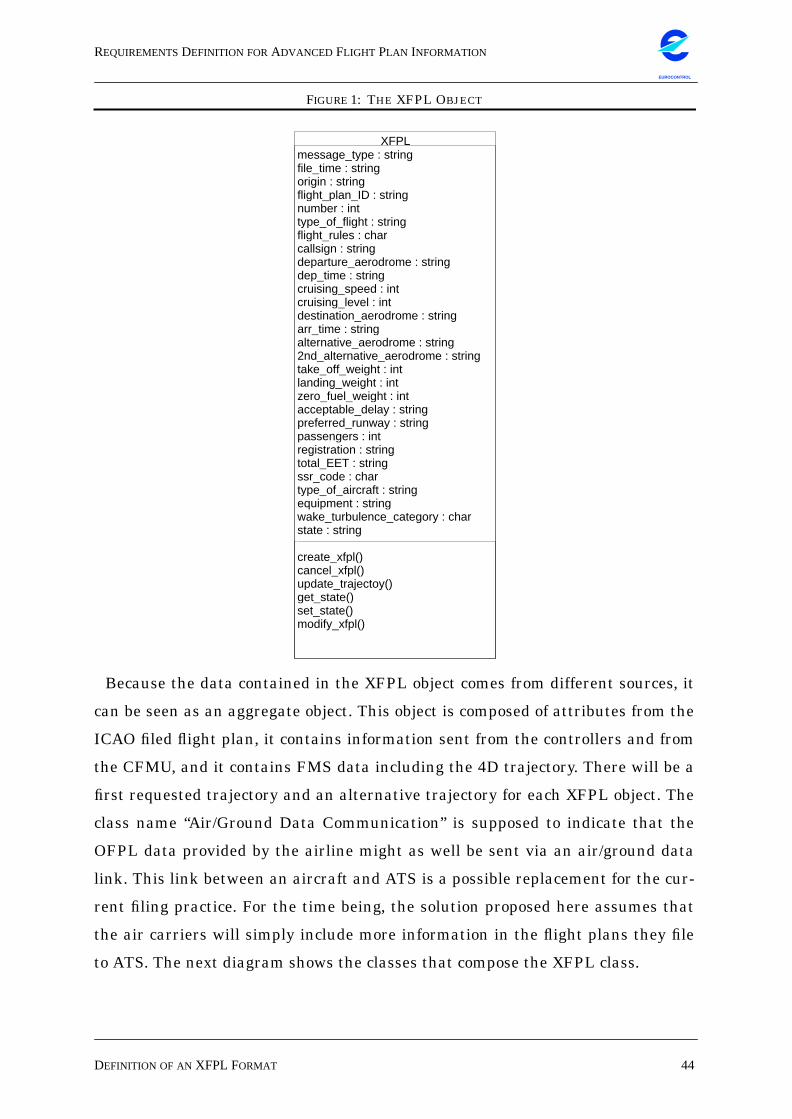
REQUIREMENTSDEFINITION FORADVANCED FLIGHT PLAN INFORMATION
DEFINITION OF AN XFPL FORMAT 44
EUROCONTROL
FIGURE 1: THE XFPL OBJECT
Because the data contained in the XFPL object comes from different sources, it
can be seen as an aggregate object. This object is composed of attributes from the
ICAO filed flight plan, it contains information sent from the controllers and from
the CFMU, and it contains FMS data including the 4D trajectory. There will be a
first requested trajectory and an alternative trajectory for each XFPL object. The
class name “Air/Ground Data Communication” is supposed to indicate that the
OFPL data provided by the airline might as well be sent via an air/ground data
link. This link between an aircraft and ATS is a possible replacement for the cur-
rent filing practice. For the time being, the solution proposed here assumes that
the air carriers will simply include more information in the flight plans they file
to ATS. The next diagram shows the classes that compose the XFPL class.
XFPLmessage_type : stringfile_time : stringorigin : stringflight_plan_ID : stringnumber : inttype_of_flight : stringflight_rules : charcallsign : stringdeparture_aerodrome : stringdep_time : stringcruising_speed : intcruising_level : intdestination_aerodrome : stringarr_time : stringalternative_aerodrome : string2nd_alternative_aerodrome : stringtake_off_weight : intlanding_weight : intzero_fuel_weight : intacceptable_delay : stringpreferred_runway : stringpassengers : intregistration : stringtotal_EET : stringssr_code : chartype_of_aircraft : stringequipment : stringwake_turbulence_category : charstate : stringcreate_xfpl()cancel_xfpl()update_trajectoy()get_state()set_state()modify_xfpl()
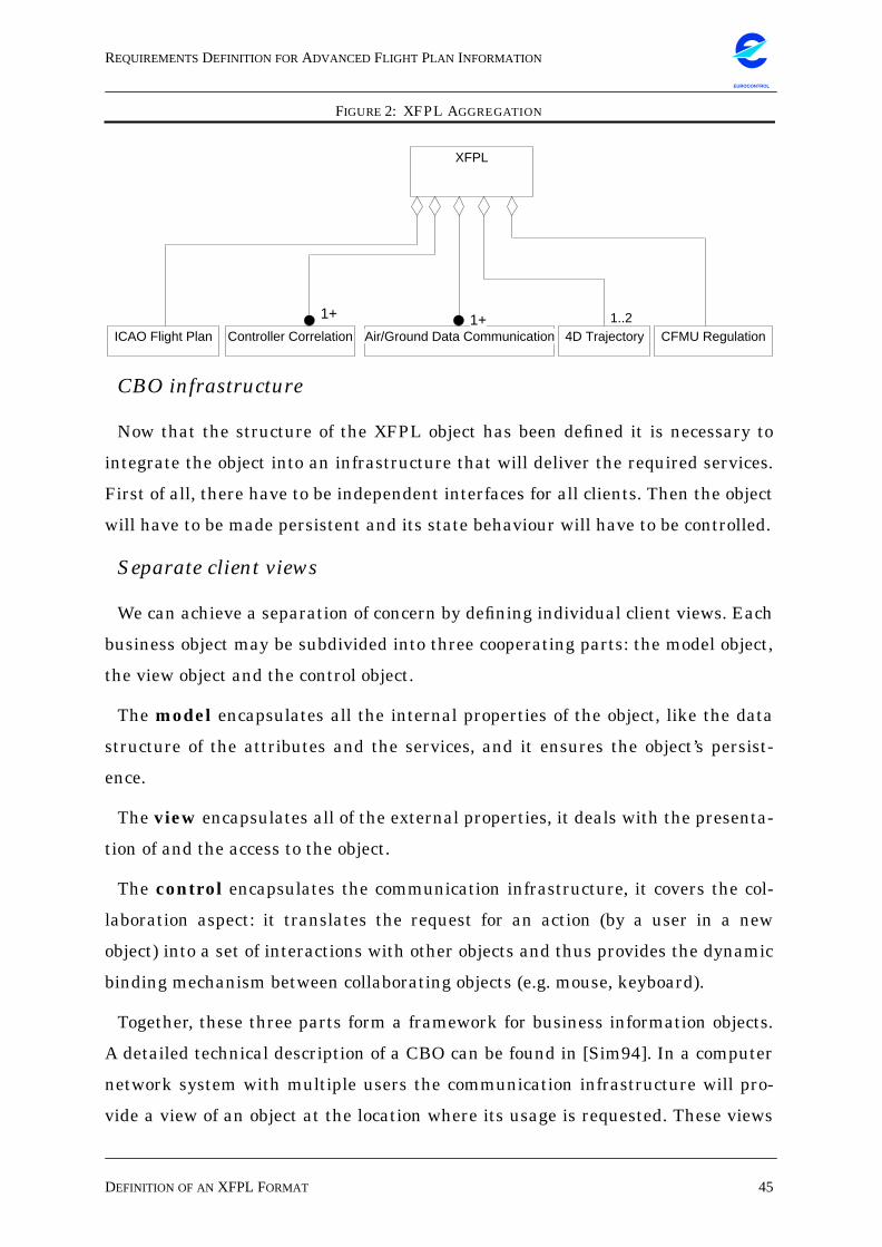
REQUIREMENTSDEFINITION FORADVANCED FLIGHT PLAN INFORMATION
DEFINITION OF AN XFPL FORMAT 45
EUROCONTROL
FIGURE 2: XFPL AGGREGATION
CBO infrastructure
Now that the structure of the XFPL object has been defined it is necessary to
integrate the object into an infrastructure that will deliver the required services.
First of all, there have to be independent interfaces for all clients. Then the object
will have to be made persistent and its state behaviour will have to be controlled.
Separate client views
We can achieve a separation of concern by defining individual client views. Each
business object may be subdivided into three cooperating parts: the model object,
the view object and the control object.
The model encapsulates all the internal properties of the object, like the data
structure of the attributes and the services, and it ensures the object’s persist-
ence.
The view encapsulates all of the external properties, it deals with the presenta-
tion of and the access to the object.
The control encapsulates the communication infrastructure, it covers the col-
laboration aspect: it translates the request for an action (by a user in a new
object) into a set of interactions with other objects and thus provides the dynamic
binding mechanism between collaborating objects (e.g. mouse, keyboard).
Together, these three parts form a framework for business information objects.
A detailed technical description of a CBO can be found in [Sim94]. In a computer
network system with multiple users the communication infrastructure will pro-
vide a view of an object at the location where its usage is requested. These views
ICAO Flight Plan
1+
Controller Correlation1+
Air/Ground Data Communication CFMU Regulation4D Trajectory
XFPL
1+ 1+ 1..2
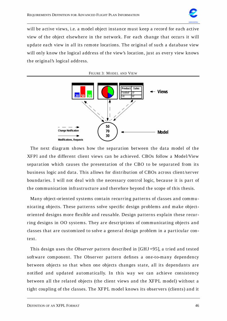
REQUIREMENTSDEFINITION FORADVANCED FLIGHT PLAN INFORMATION
DEFINITION OF AN XFPL FORMAT 46
EUROCONTROL
will be active views, i.e. a model object instance must keep a record for each active
view of the object elsewhere in the network. For each change that occurs it will
update each view in all its remote locations. The original of such a database view
will only know the logical address of the view’s location, just as every view knows
the original’s logical address.
FIGURE 3: MODEL AND VIEW
The next diagram shows how the separation between the data model of the
XFPl and the different client views can be achieved. CBOs follow a Model/View
separation which causes the presentation of the CBO to be separated from its
business logic and data. This allows for distribution of CBOs across client/server
boundaries. I will not deal with the necessary control logic, because it is part of
the communication infrastructure and therefore beyond the scope of this thesis.
Many object-oriented systems contain recurring patterns of classes and commu-
nicating objects. These patterns solve specific design problems and make object-
oriented designs more flexible and reusable. Design patterns explain these recur-
ring designs in OO systems. They are descriptions of communicating objects and
classes that are customized to solve a general design problem in a particular con-
text.
This design uses the Observer pattern described in [GHJ+95], a tried and tested
software component. The Observer pattern defines a one-to-many dependency
between objects so that when one objects changes state, all its dependants are
notified and updated automatically. In this way we can achieve consistency
between all the related objects (the client views and the XFPL model) without a
tight coupling of the classes. The XFPL model knows its observers (clients) and it
20 50 30
Product Sales
Football 20Ski 50
507030
Model
Views
Modifications, Requests
Change Notification
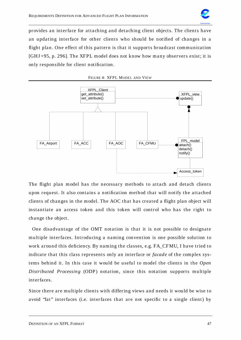
REQUIREMENTSDEFINITION FORADVANCED FLIGHT PLAN INFORMATION
DEFINITION OF AN XFPL FORMAT 47
EUROCONTROL
provides an interface for attaching and detaching client objects. The clients have
an updating interface for other clients who should be notified of changes in a
flight plan. One effect of this pattern is that it supports broadcast communication
[GHJ+95, p. 296]. The XFPL model does not know how many observers exist; it is
only responsible for client notification.
FIGURE 4: XFPL MODEL AND VIEW
The flight plan model has the necessary methods to attach and detach clients
upon request. It also contains a notification method that will notify the attached
clients of changes in the model. The AOC that has created a flight plan object will
instantiate an access token and this token will control who has the right to
change the object.
One disadvantage of the OMT notation is that it is not possible to designate
multiple interfaces. Introducing a naming convention is one possible solution to
work around this deficiency. By naming the classes, e.g. FA_CFMU, I have tried to
indicate that this class represents only an interface or facade of the complex sys-
tems behind it. In this case it would be useful to model the clients in the Open
Distributed Processing (ODP) notation, since this notation supports multiple
interfaces.
Since there are multiple clients with differing views and needs it would be wise to
avoid “fat” interfaces (i.e. interfaces that are not specific to a single client) by
FA_Airport FA_ACC FA_AOC FA_CFMU
Access_token
XFPL_Clientget_attribute()set_attribute()
FPL_modelattach()detach()notify()
XFPL_viewupdate()
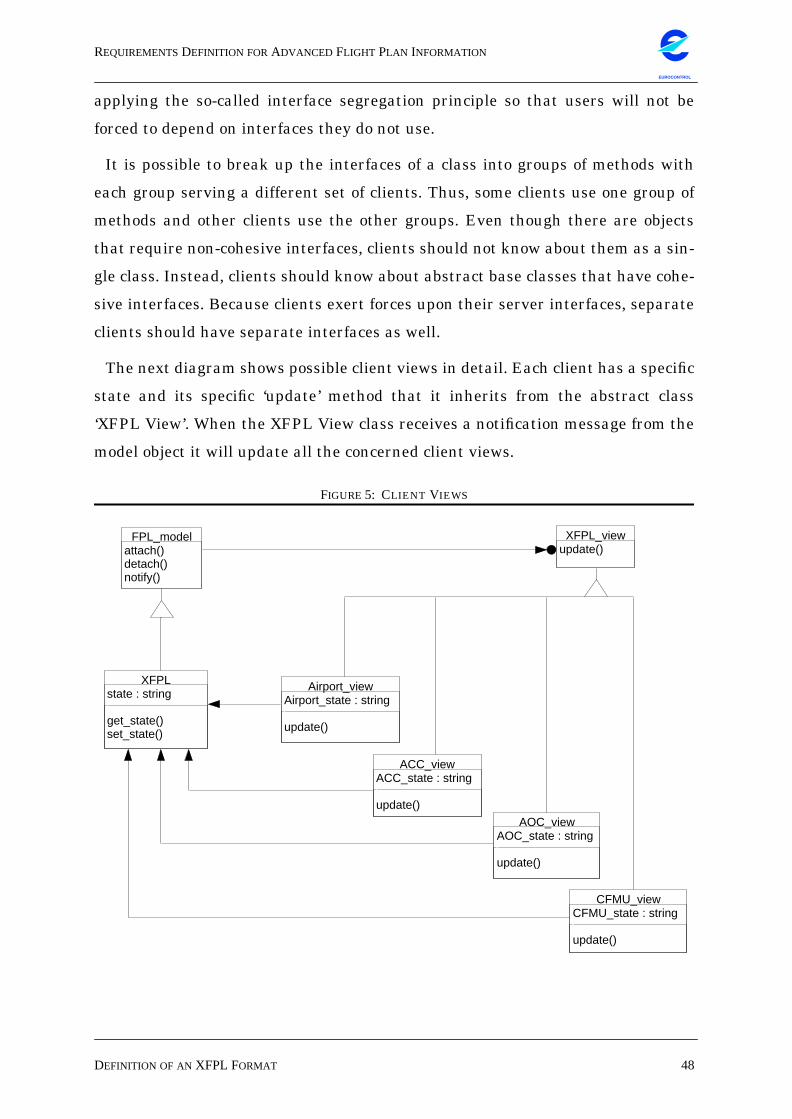
REQUIREMENTSDEFINITION FORADVANCED FLIGHT PLAN INFORMATION
DEFINITION OF AN XFPL FORMAT 48
EUROCONTROL
applying the so-called interface segregation principle so that users will not be
forced to depend on interfaces they do not use.
It is possible to break up the interfaces of a class into groups of methods with
each group serving a different set of clients. Thus, some clients use one group of
methods and other clients use the other groups. Even though there are objects
that require non-cohesive interfaces, clients should not know about them as a sin-
gle class. Instead, clients should know about abstract base classes that have cohe-
sive interfaces. Because clients exert forces upon their server interfaces, separate
clients should have separate interfaces as well.
The next diagram shows possible client views in detail. Each client has a specific
state and its specific ‘update’ method that it inherits from the abstract class
‘XFPL View’. When the XFPL View class receives a notification message from the
model object it will update all the concerned client views.
FIGURE 5: CLIENT VIEWS
XFPL_viewupdate()
FPL_modelattach()detach()notify()
Airport_viewAirport_state : stringupdate()
ACC_viewACC_state : stringupdate()
AOC_viewAOC_state : stringupdate()
XFPLstate : stringget_state()set_state()
CFMU_viewCFMU_state : stringupdate()
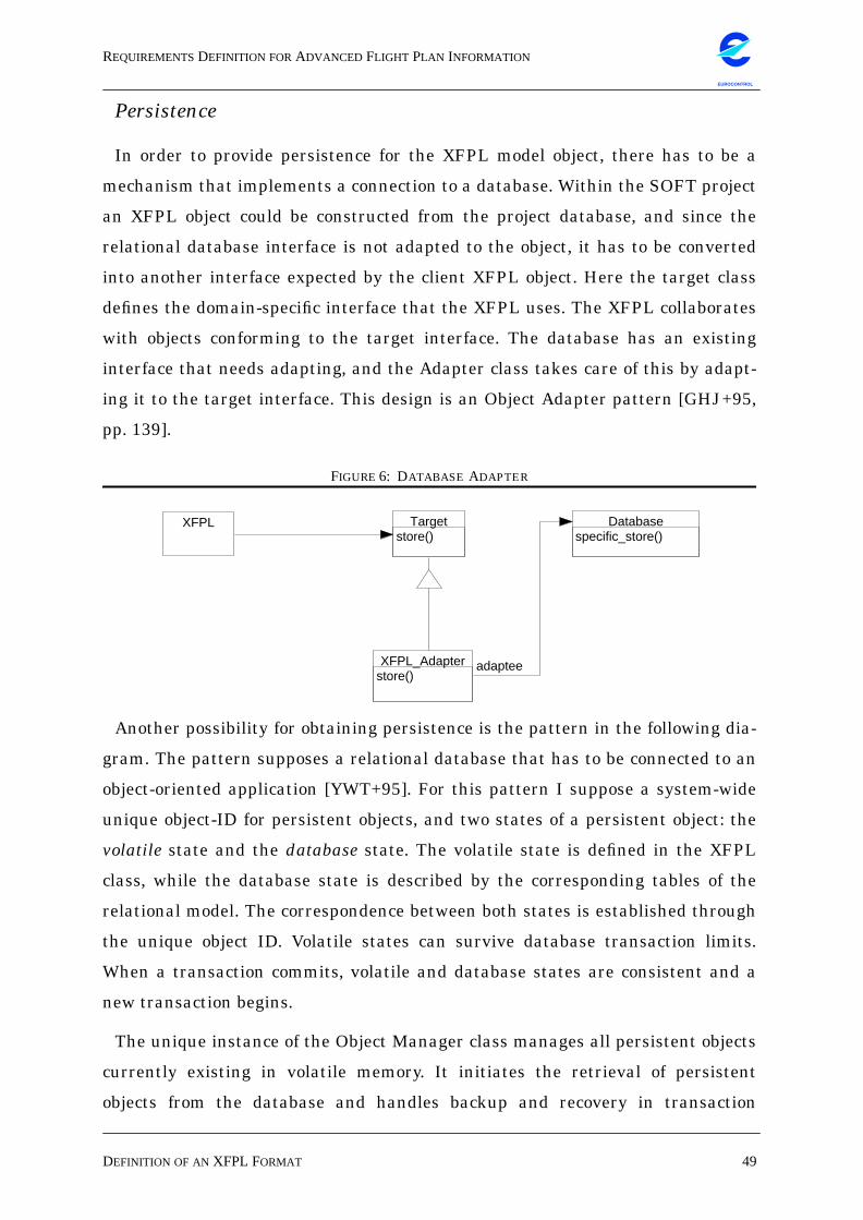
REQUIREMENTSDEFINITION FORADVANCED FLIGHT PLAN INFORMATION
DEFINITION OF AN XFPL FORMAT 49
EUROCONTROL
Persistence
In order to provide persistence for the XFPL model object, there has to be a
mechanism that implements a connection to a database. Within the SOFT project
an XFPL object could be constructed from the project database, and since the
relational database interface is not adapted to the object, it has to be converted
into another interface expected by the client XFPL object. Here the target class
defines the domain-specific interface that the XFPL uses. The XFPL collaborates
with objects conforming to the target interface. The database has an existing
interface that needs adapting, and the Adapter class takes care of this by adapt-
ing it to the target interface. This design is an Object Adapter pattern [GHJ+95,
pp. 139].
FIGURE 6: DATABASE ADAPTER
Another possibility for obtaining persistence is the pattern in the following dia-
gram. The pattern supposes a relational database that has to be connected to an
object-oriented application [YWT+95]. For this pattern I suppose a system-wide
unique object-ID for persistent objects, and two states of a persistent object: the
volatile state and the database state. The volatile state is defined in the XFPL
class, while the database state is described by the corresponding tables of the
relational model. The correspondence between both states is established through
the unique object ID. Volatile states can survive database transaction limits.
When a transaction commits, volatile and database states are consistent and a
new transaction begins.
The unique instance of the Object Manager class manages all persistent objects
currently existing in volatile memory. It initiates the retrieval of persistent
objects from the database and handles backup and recovery in transaction
Targetstore()
XFPL
XFPL_Adapterstore()
Databasespecific_store()
adaptee
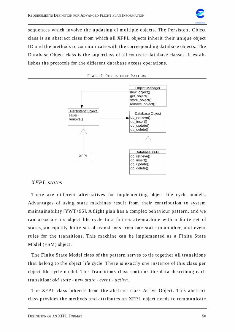
REQUIREMENTSDEFINITION FORADVANCED FLIGHT PLAN INFORMATION
DEFINITION OF AN XFPL FORMAT 50
EUROCONTROL
sequences which involve the updating of multiple objects. The Persistent Object
class is an abstract class from which all XFPL objects inherit their unique object
ID and the methods to communicate with the corresponding database objects. The
Database Object class is the superclass of all concrete database classes. It estab-
lishes the protocols for the different database access operations.
FIGURE 7: PERSISTENCE PATTERN
XFPL states
There are different alternatives for implementing object life cycle models.
Advantages of using state machines result from their contribution to system
maintainability [YWT+95]. A flight plan has a complex behaviour pattern, and we
can associate its object life cycle to a finite-state-machine with a finite set of
states, an equally finite set of transitions from one state to another, and event
rules for the transitions. This machine can be implemented as a Finite State
Model (FSM) object.
The Finite State Model class of the pattern serves to tie together all transitions
that belong to the object life cycle. There is exactly one instance of this class per
object life cycle model. The Transitions class contains the data describing each
transition: old state - new state - event - action.
The XFPL class inherits from the abstract class Active Object. This abstract
class provides the methods and attributes an XFPL object needs to communicate
XFPLDatabase XFPL
db_retrieve()db_insert()db_update()db_delete()
Database Objectdb_retrieve()db_insert()db_update()db_delete()
Persistent Objectsave()remove()
Object Managernew_object()get_object()store_object()remove_object()
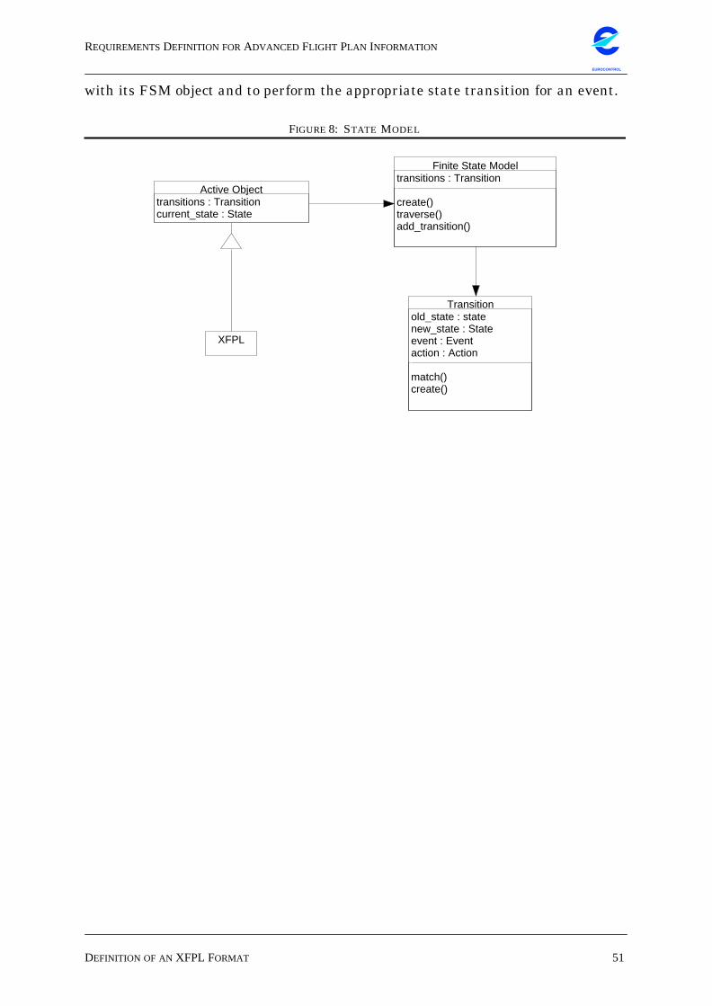
REQUIREMENTSDEFINITION FORADVANCED FLIGHT PLAN INFORMATION
DEFINITION OF AN XFPL FORMAT 51
EUROCONTROL
with its FSM object and to perform the appropriate state transition for an event.
FIGURE 8: STATE MODEL
XFPL
Transitionold_state : statenew_state : Stateevent : Eventaction : Actionmatch()create()
Finite State Modeltransitions : Transitioncreate()traverse()add_transition()
Active Objecttransitions : Transitioncurrent_state : State
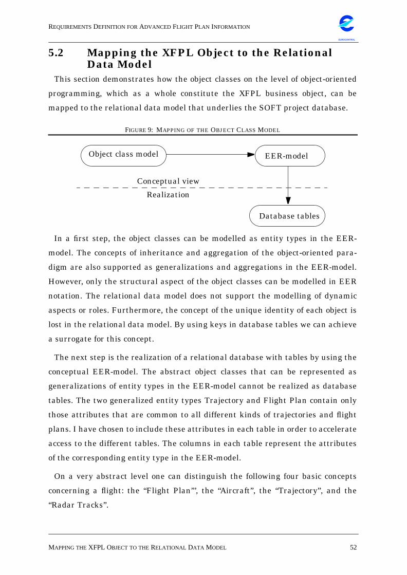
REQUIREMENTSDEFINITION FORADVANCED FLIGHT PLAN INFORMATION
MAPPING THEXFPL OBJECT TO THERELATIONAL DATA MODEL 52
EUROCONTROL
5.2 Mapping the XFPL Object to the RelationalData Model
This section demonstrates how the object classes on the level of object-oriented
programming, which as a whole constitute the XFPL business object, can be
mapped to the relational data model that underlies the SOFT project database.
FIGURE 9: MAPPING OF THE OBJECT CLASS MODEL
In a first step, the object classes can be modelled as entity types in the EER-
model. The concepts of inheritance and aggregation of the object-oriented para-
digm are also supported as generalizations and aggregations in the EER-model.
However, only the structural aspect of the object classes can be modelled in EER
notation. The relational data model does not support the modelling of dynamic
aspects or roles. Furthermore, the concept of the unique identity of each object is
lost in the relational data model. By using keys in database tables we can achieve
a surrogate for this concept.
The next step is the realization of a relational database with tables by using the
conceptual EER-model. The abstract object classes that can be represented as
generalizations of entity types in the EER-model cannot be realized as database
tables. The two generalized entity types Trajectory and Flight Plan contain only
those attributes that are common to all different kinds of trajectories and flight
plans. I have chosen to include these attributes in each table in order to accelerate
access to the different tables. The columns in each table represent the attributes
of the corresponding entity type in the EER-model.
On a very abstract level one can distinguish the following four basic concepts
concerning a flight: the “Flight Plan”’, the “Aircraft”, the “Trajectory”, and the
“Radar Tracks”.
Object class model EER-model
Database tables
Conceptual view
Realization
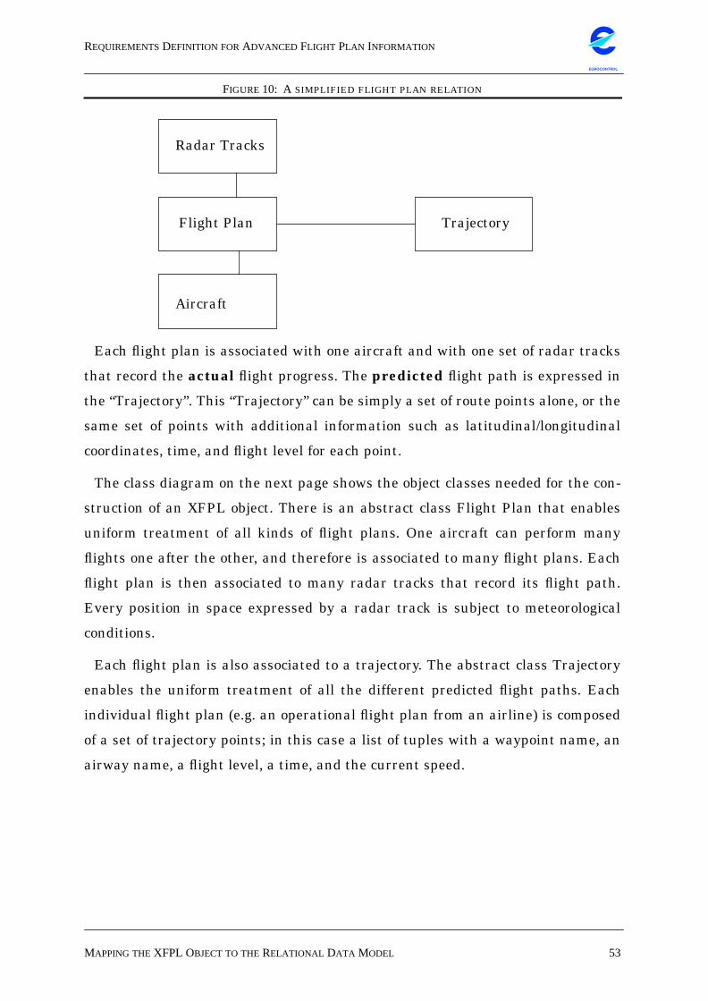
REQUIREMENTSDEFINITION FORADVANCED FLIGHT PLAN INFORMATION
MAPPING THEXFPL OBJECT TO THERELATIONAL DATA MODEL 53
EUROCONTROL
FIGURE 10: A SIMPLIFIED FLIGHT PLAN RELATION
Each flight plan is associated with one aircraft and with one set of radar tracks
that record the actual flight progress. The predicted flight path is expressed in
the “Trajectory”. This “Trajectory” can be simply a set of route points alone, or the
same set of points with additional information such as latitudinal/longitudinal
coordinates, time, and flight level for each point.
The class diagram on the next page shows the object classes needed for the con-
struction of an XFPL object. There is an abstract class Flight Plan that enables
uniform treatment of all kinds of flight plans. One aircraft can perform many
flights one after the other, and therefore is associated to many flight plans. Each
flight plan is then associated to many radar tracks that record its flight path.
Every position in space expressed by a radar track is subject to meteorological
conditions.
Each flight plan is also associated to a trajectory. The abstract class Trajectory
enables the uniform treatment of all the different predicted flight paths. Each
individual flight plan (e.g. an operational flight plan from an airline) is composed
of a set of trajectory points; in this case a list of tuples with a waypoint name, an
airway name, a flight level, a time, and the current speed.
TrajectoryFlight Plan
Radar Tracks
Aircraft
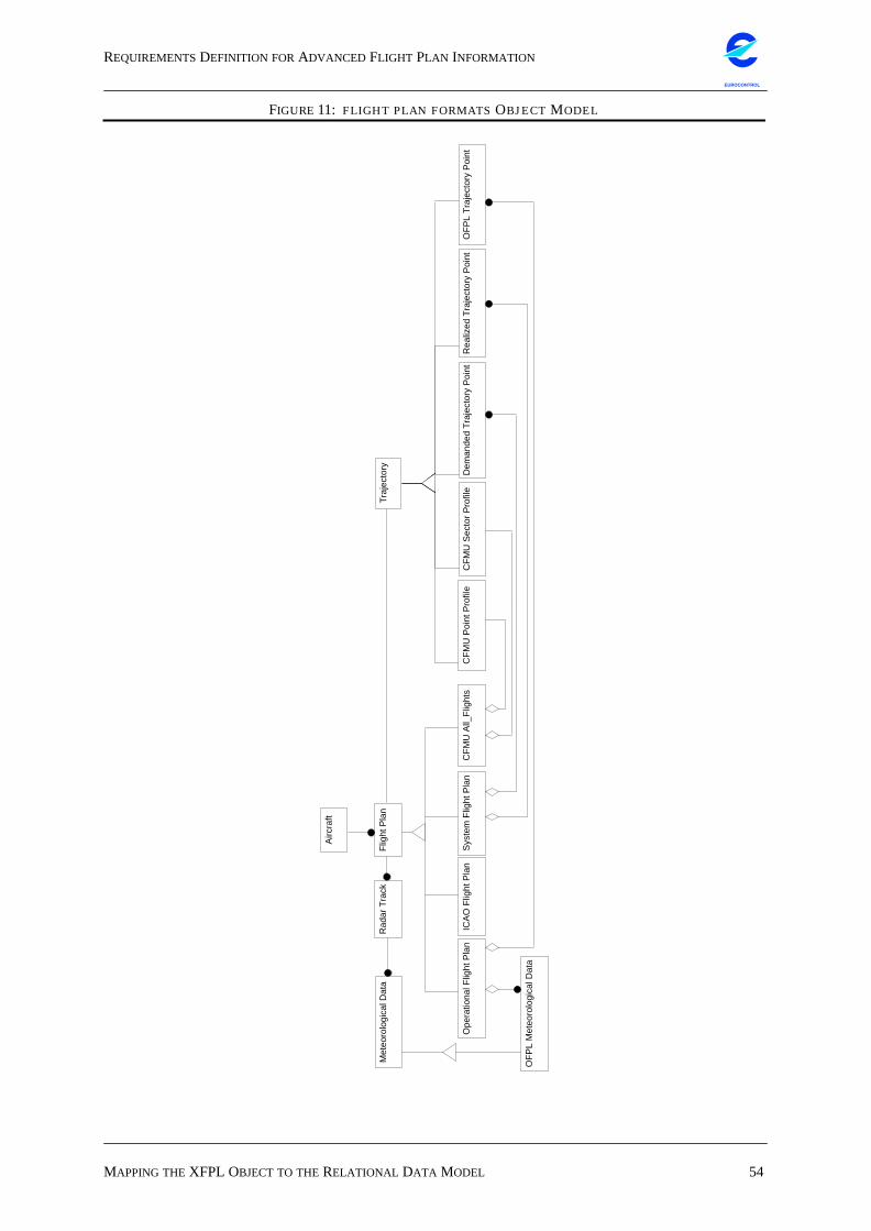
REQUIREMENTSDEFINITION FORADVANCED FLIGHT PLAN INFORMATION
MAPPING THEXFPL OBJECT TO THERELATIONAL DATA MODEL 54
EUROCONTROL
FIGURE 11: FLIGHT PLAN FORMATS OBJECT MODEL
ICA
O F
light
Pla
n
Met
eoro
logi
cal D
ata
OF
PL
Met
eoro
logi
cal D
ata
Ope
ratio
nal F
light
Pla
nO
FP
L T
raje
ctor
y P
oint
Rea
lized
Tra
ject
ory
Poi
ntS
yste
m F
light
Pla
nD
eman
ded
Tra
ject
ory
Poi
ntC
FM
U S
ecto
r P
rofil
eC
FM
U A
ll_F
light
sC
FM
U P
oint
Pro
file
Rad
ar T
rack
Airc
raft
Flig
ht P
lan
Tra
ject
ory
REQUIREMENTSDEFINITION FORADVANCED FLIGHT PLAN INFORMATION
MAPPING THEXFPL OBJECT TO THERELATIONAL DATA MODEL 55
EUROCONTROL
Now this object model has to be mapped to a relational data model for the rela-
tional SOFT database.
This is a brief description of the 15 entity types in the EER-model:
• Meteorological Data: has attributes describing wind direction, wind force,
and air temperature as provided by Météo France.
• Radar Trajectory Point: has attributes describing radar tracks for all flights
that were recorded in the CRNA Reims and the CRNA Athis-Mons. This rela-
tion does not qualify as a specialization of the Trajectory relation, because,
unlike the system flight plans for instance, it contains radar tracks (recorded
flight path) and not waypoint or sector names (predicted flight path).
• Flight Plan: this entity type is a generalization of the four different flight plan
formats; it contains only the attributes common to all flight plans.
• Aircraft: has attributes describing each physical aircraft observed in the con-
cerned area.
• CFMU_All_Flights: this is a specialized flight plan; it is also an aggregation
of two flight profiles calculated by the CFMU after slot allocation and an even-
tual regulation.
• System Flight Plan: this is also a specialization of a flight plan; it is an aggre-
gation of two possibly different trajectories recorded in the CRNA Reims and
Athis-Mons (the database table System Flight Plan will be filled with data
extracted from SFPLs in the COURAGE format).
• Operational Flight Plan: a specialization from the Flight Plan entity type; it
contains the attributes of the operational flight plans used by the airlines that
the pilots receive before take-off. This entity type is an aggregation of the flight
trajectory calculated by the airline, and the meteorological information used
for the calculation.
• ICAO Flight Plan: a specialization of the Flight Plan entity type; contains all
the attributes from the ICAO filed flight plan.
• Trajectory: a generalization of all kinds of predicted flight paths.
• CFMU_Sector Profile: contains one of the two components of the
CFMU__All_Flights entity type; the list of the traversed sectors for each flight.
• CFMU_Point Profile: contains the other of the two components of the
CFMU__All_Flights entity type; a list of waypoints for each flight.
REQUIREMENTSDEFINITION FORADVANCED FLIGHT PLAN INFORMATION
MAPPING THEXFPL OBJECT TO THERELATIONAL DATA MODEL 56
EUROCONTROL
• SFPL_Realized Trajectory Point: contains atributes describing a flight tra-
jectory that is possibly different from the demanded trajectory due to controller
actions.
• SFPL_Demanded Trajectory Point: contains the attributes of a flight tra-
jectory as it was originally requested in the flight plan.
• OFPL_Trajectory Point: one of the two components of the OFPL entity type;
contains the flight route as it was predicted by the airline.
• OFPL_Meteorological Data: the other component of the OFPL entity type;
contains the attributes describing meteorological information used by the air-
line to predict a precise flight trajectory.
The following diagram represents the relational database schema for the SOFT
project database in EER notation.
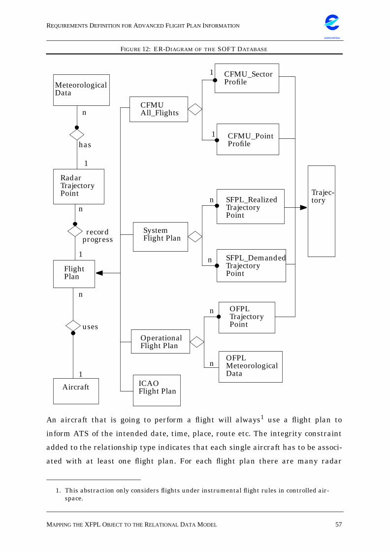
REQUIREMENTSDEFINITION FORADVANCED FLIGHT PLAN INFORMATION
MAPPING THEXFPL OBJECT TO THERELATIONAL DATA MODEL 57
EUROCONTROL
FIGURE 12: ER-DIAGRAM OF THE SOFT DATABASE
An aircraft that is going to perform a flight will always1 use a flight plan to
inform ATS of the intended date, time, place, route etc. The integrity constraint
added to the relationship type indicates that each single aircraft has to be associ-
ated with at least one flight plan. For each flight plan there are many radar
1. This abstraction only considers flights under instrumental flight rules in controlled air-space.
SystemFlight Plan
SFPL_RealizedTrajectoryPoint
SFPL_DemandedTrajectoryPoint
CFMU_PointProfile
CFMU_SectorProfile
1
1
n
n
OFPLTrajectoryPoint
OFPLMeteorologicalData
OperationalFlight Plan
ICAOFlight Plan
MeteorologicalData
RadarTrajectoryPoint
FlightPlan
n
1
n
1
Aircraft
1
n
CFMUAll_Flights
n
n
Trajec-tory
has
progress
uses
record
REQUIREMENTSDEFINITION FORADVANCED FLIGHT PLAN INFORMATION
MAPPING THEXFPL OBJECT TO THERELATIONAL DATA MODEL 58
EUROCONTROL
tracks which as a whole compose the flight’s actually recorded progress. There
should only be radar tracks for those flights for which we have the flight plan. So
there is another integrity constraint on this relationship type to indicate its total-
ity.
Each point in space represented by a radar track has certain meteorological con-
ditions that are modelled in the Meteorological Data entity type. Due to the qual-
ity of the meteorological data it is necessary to interpolate between different sets
of weather information to evaluate the temperature, wind force and heading for
each radar track. So each radar track has different meteorological data that
serves to calculate its approximate weather conditions, and the integrity con-
straint on the relationship type expresses that each tuple of meteorological data
has to be associated with one radar track.
The Flight Plan entity type is a generalization of four different entity types: The
CFMU All_Flights flight plan, the System Flight Plan, the Operational Flight
Plan, and the ICAO Flight Plan.
The CFMU All_Flights flight plan is an aggregation of one CFMU_Sector Profile
and of one CFMU_Point Profile. The integrity constraints on both profile entity
types indicate that each profile has to be associated to one CFMU All_Flights
flight plan.
The System Flight Plan entity type is an aggregation of many SFPL_Realized
Trajectory Points and of many SFPL_Demanded Trajectory Points. Here also,
there are integrity constraints on both components to indicate that they have to
be associated to one System Flight Plan.
The Operational Flight Plan entity type is an aggregation of the OFPL Trajec-
tory Point entity type and of the OFPL Meteorological Data entity type. There is
an integrity constraint for the relationship between the trajectory points and the
OFPL because the OFPL trajectory points always have to be associated to one
OFPL.
Finally, the Trajectory entity type is a generalization of the five different trajec-
tory entity types: CFMU_Sector Profile, CFMU_Point Profile, SFPL Realized Tra-
jectory Point, SFPL Demanded Trajectory Point, and OFPL Trajectory Point. The
REQUIREMENTSDEFINITION FORADVANCED FLIGHT PLAN INFORMATION
MAPPING THEXFPL OBJECT TO THERELATIONAL DATA MODEL 59
EUROCONTROL
Trajectory entity type has the attributes that are common to all the different
trajectories.
From this relational data model I have created a database in ORACLE 7 contain-
ing the following tables and attributes:
THE OPERATIONAL FLIGHT PLAN TABLE
Primary keys:
• ADEP: Departure airport in ICAO code.
• ADES: Destination airport in ICAO code.
• Callsign: Callsign of the aircraft.
• Date_Dep: Date of departure; may be different from the date the flight passes
over a waypoint.
Mandatory attributes:
• Planned_Arr_Time: Arrival time in UTC as planned by the airline before take-
off.
• Planned_Dep_Time: Departure time in UTC as planned by the airline before
take-off.
Optional attributes:
• Avge_Temperature: Average outside air temperature in degrees Celsius at
cruise flight level according to weather forecast.
• Avge_Wind: Average wind component at cruise flight level, according to
weather forecast.
• Avge_Wind_Heading: Average wind heading at cruise flight level in degrees
relative to the aircraft’s heading.
• Avge_Wind_Magnitude: Average wind magnitude in knots at cruise flight level,
according to weather forecast.
• Climb_Speed: Planned ground speed during climb in knots.
• Cruise_Flight_Level: Cruise flight level in feet*100 planned by the airline.
• Cruise_Machnumber: Cruise speed planned by the airline, expressed as mach-
number.
REQUIREMENTSDEFINITION FORADVANCED FLIGHT PLAN INFORMATION
MAPPING THEXFPL OBJECT TO THERELATIONAL DATA MODEL 60
EUROCONTROL
• Cruise_Speed: Planned ground speed for cruise in knots.
• Descent_Speed: Planned ground speed during descent in knots.
• Landing_Weight: Planned landing weight of the aircraft in kg.
• Take_Off_Weight: Planned take-off weight of the aircraft in kg.
• Taxi_Fuel: Planned amount of fuel in kg needed for taxiing at the departure
aerodrome.
• Zero_Fuel_weight: Planned zero-fuel weight of the aircraft in kg.
Taxi fuel is added here because the real take-off weight will be the planned take-
off weight minus the fuel burned during taxiing. This table receives two foreign
keys from the Aircraft table: AC_Type and Registration. Since the different air-
lines use different sets of data, most of the attributes are optional.
THE TRAJECTORY TABLE
Primary keys:
• ADEP: Departure airport in ICAO code.
• ADES: Destination airport in ICAO code.
• Callsign: Callsign of the aircraft.
• Date_Dep: Date of departure; may be different from the date the flight passes
over a waypoint.
• Waypoint: This may be either the name of a beacon or of a reporting point.
Mandatory attributes:
• Delta_Time: The estimated time (hours:minutes) it will take the aircraft to get
to the next waypoint.
• Total_Time: The estimated total time (hours:minutes) elapsed at this point
since take-off.
• Date_Over: This is the date when the aircraft crosses a waypoint; may be dif-
ferent from the departure date if the flight has left late at night and only
arrives the following day.
REQUIREMENTSDEFINITION FORADVANCED FLIGHT PLAN INFORMATION
MAPPING THEXFPL OBJECT TO THERELATIONAL DATA MODEL 61
EUROCONTROL
THE OFPL TRAJECTORY POINT TABLE
Primary keys:
• Date_Over: This is the date when the aircraft crosses a waypoint; may be dif-
ferent from the departure date if the flight has left late at night and only
arrives the following day.
• Waypoint: This may be either the name of a beacon or of a reporting point.
Mandatory attributes:
• Delta_Time: The estimated time (hours:minutes) it will take the aircraft to get
to the next waypoint.
• Total_Time: The estimated total time (hours:minutes) elapsed at this point
since take-off.
Optional attributes:
• Airway: The name of the airway the waypoint is on, if any.
• Beacon_Frequency: The frequency emitted by a beacon in MHz.
• Delta_Distance: This is the estimated ground distance in nautical miles
between the current waypoint and the next one.
• Delta_Fuel_Burn: This is the estimated amount of fuel in kg burned until
reaching the next waypoint.
• FL_Over_WPT: The flight level in feet*100 at which the aircraft crosses the
waypoint.
• Ground_Speed: The ground speed in knots at which the aircraft crosses the
waypoint.
• Latitude_WPT: The latitude coordinate of the waypoint, according to WGS 84.
• Longitude_WPT: The longitude coordinate of the waypoint, according to WGS
84.
• Machnumber: The speed expressed as machnumber at which the aircraft
crosses the waypoint.
• Magnetic_Track: The magnetic track of the aircraft at crossing the waypoint.
• MORA: The minimum off-route altitude in feet*100 at this point.
• Remaining_Fuel: The amount of fuel in kg remaining at this point.
REQUIREMENTSDEFINITION FORADVANCED FLIGHT PLAN INFORMATION
MAPPING THEXFPL OBJECT TO THERELATIONAL DATA MODEL 62
EUROCONTROL
• Total_Distance: This is the total ground distance in nautical miles flown since
take-off.
• True_Air_Speed: The true air speed in knots while crossing a waypoint.
This table has a relationship to the OFPL table, since the data contained in it
has the same origin, i.e. the air carrier. For one flight there are one or many tra-
jectory points that as a whole constitute the aircraft’s predicted trajectory.
Because the different contacted airlines have widely differing sets of data in their
respective OFPLs, many of the attributes in this table are optional. To identify
each row, this table receives four foreign keys from the OFPL table: ADEP, ADES,
Callsign, Date_Dep.
THE CFMU ALL FLIGHTS TABLE
Mandatory attributes:
• AC_TYPE: This is the ICAO standard abbreviation for the aircraft type.
• AOBT: The actual off-block time in UTC.
• EOBT: The estimated off-block time in UTC.
• FIRST_REQ_FL: The pilot’s first requested flight level for the flight in feet *
100.
• FLIGHT_STATUS: This is the status of the flight: TE for “terminated”, CA for
“cancelled”, AA for “ATC activated”, FI for “filed”, FS for “filed and slot issued”,
TA for “tact activated”.
• IFPS_ID: The ID number issued to the flight by the IFPS.
• IOBT: This is the initially estimated off-block time in UTC.
• LATE_FILER: This field indicated if or if not the flight plan was filed later
than EOBT - 3h.
• LATE_UPDATER: This field indicated if or if not the flight plan was filed later
than EOBT - 3h.
• TACT_ID: This is the ID number issued to the flight by the CFMU TACT sys-
tem.
Optional attributes:
• COBT: This is the calculated off-block time in UTC from the CFMU.
REQUIREMENTSDEFINITION FORADVANCED FLIGHT PLAN INFORMATION
MAPPING THEXFPL OBJECT TO THERELATIONAL DATA MODEL 63
EUROCONTROL
• SAM_CTOT: The slot allocation message for the calculated take-off time
(CTOT).
• SIP_CTOT: The slot improvement proposal for the CTOT.
• SLOT_FORCED: This field indicates if the slot has been forced on a flight
[Y|N].
This table contains data from the CFMU file “All Flights”, which is generated at
the CFMU after any necessary regulation and it contains the estimated as well as
the calculated and actual take-off slots. For each OFPL row there may be zero or
one rows in the CFMU_All_Flights table, while each row in the
CFMU_ALL_FLIGHTS table refers to exactly one row in the OFPL table. To iden-
tify each row this table receives four foreign keys from the OFPL table: ADEP,
ADES, CALLSIGN, DATE_DEP.
THE CFMU SECTOR PROFILE TABLE
Primary keys:
• Date_Over: This is the date when the flight has passed over the waypoint; pos-
sibly different from the day it took off at the departure aerodrome.
• Sector: This is the name of the sector flown over.
Mandatory attributes:
• Entry_Time: The time UTC when a flight enters the sector.
• Exit_Time: The time UTC when a flight leaves the sector.
Optional attributes:
• Airway: The name of an airway, if the waypoint is situated on it.
This table lists the sectors crossed by a given flight with the entry and exit times
for each sector. For each row in the CFMU_All_Flights table there are one or
many rows in the Sector_Profile table, each of which describes a sector in the air-
craft’s trajectory. To identify each row this table receives four foreign keys from
the CFMU_All_Flights table: ADEP, ADES, Callsign, Date_Dep.
REQUIREMENTSDEFINITION FORADVANCED FLIGHT PLAN INFORMATION
MAPPING THEXFPL OBJECT TO THERELATIONAL DATA MODEL 64
EUROCONTROL
THE CFMU POINT PROFILE TABLE
Primary keys:
• Date_Over: This is the date when the flight has passed over the waypoint; pos-
sibly different from the day it took off at the departure aerodrome.
• Waypoint: The name of a waypoint (e.g. reporting point or beacon).
Mandatory attributes:
• Flight Level: This is the flight level in feet * 100.
• Time_Over: This is the time UTC when a flight passes over a waypoint.
Optional attributes:
• Airway: The name of an airway, if the waypoint is situated on it.
For each row in the CFMU_All_Flights table there are one or many rows in the
Point_Profile table, each of which describes a waypoint in the aircraft’s trajectory
as calculated at the CFMU. To identify each row this table receives four foreign
keys from the CFMU_All_Flights table: ADEP, ADES, Callsign, Date_Dep.
THE RADAR TRAJECTORY POINT TABLE
Primary keys:
• Time_Over: The time UTC hours`h`minutes`:`seconds’, for each radar track.
Mandatory attributes:
• Date_Over: This is the day when the radar track was recorded; possibly differ-
ent from the day the flight took off at the departure aerodrome.
• Flight Level: This is the flight level in feet * 100.
• Ground Speed: This is the ground speed in knots.
• Latitude: For each radar track there is a WGS84 latitudinal position
degrees[N|S]minutes’seconds
• LONGITUDE: For each radar track there is a WGS84 longitudinal position
degrees[E|W]minutes’seconds
For each flight described in the OFPL there are zero or many rows in the radar
REQUIREMENTSDEFINITION FORADVANCED FLIGHT PLAN INFORMATION
MAPPING THEXFPL OBJECT TO THERELATIONAL DATA MODEL 65
EUROCONTROL
trajectory point table, each of which describes a radar track in the aircraft’s tra-
jectory. There is one radar track every 8 sec, the LAT/LONG positions for each
flight have a precision of 1” which corresponds to ~30 metres on the equator. This
table receives four foreign keys from the Flight Plan table: ADEP, ADES, CALL-
SIGN, DATE_DEP.
THE METEOROLOGICAL DATA TABLE
Primary keys:
• Date: The date when the data was recorded.
• FL_as_Isobar: The flight level expressed as air pressure in steps of 10,000 feet;
i.e. there are values for FL 100, 200, 300, 400, 500.
• Latitude_Cube: This figure gives the latitude coordinate in degrees and 1/100
of a degree: e.g. `LATITUDE 2750’ means two degrees and 45 minutes (75/100
of a degree).
• Longitude_Cube: This figure gives the longitude coordinate in degrees and 1/
100 of a degree.
• Time: There are data for every three hours UTC time: 3.00, 6.00, 9.00, 12.00,
15.0, 18.00, 21.00, 24.00.
Mandatory attributes:
• Temperature: This is the outside air temperature in degrees Kelvin.
• Wind_Heading: This is the wind heading in degrees relative to the aircraft’s
heading.
• Wind_Magnitude: This is the wind magnitude in metres/second.
This table is filled with actual weather data received from Météo France. It will
be necessary to interpolate several sets of weather data in order to obtain a good
approximation for the real weather conditions at a given point in an aircraft’s tra-
jectory. This is because Météo France provides meteorological information for
every three hours UTC time. The measurements are taken at intervals of 10,000
feet up to an altitude of 50,000 feet; they are expressed not as flight levels but as
air pressure, so that the exact altitude may vary. Longitude and latitude coordi-
nates together with the altitude define a cube in space. For each latitude value in
REQUIREMENTSDEFINITION FORADVANCED FLIGHT PLAN INFORMATION
MAPPING THEXFPL OBJECT TO THERELATIONAL DATA MODEL 66
EUROCONTROL
a file from Météo France, there are ten longitude values in steps of 15 minutes.
Each following latitude value is then also increased by 15 minutes. For this cube
in time and space, there is information about the temperature, the wind direction,
and the wind force.
Since the units metres/second, degrees Kelvin, and 1/1000 of a degree are not
the same as in the other tables with columns for wind speed, temperature, and
lat/long coordinates, these have to be converted before entering them into the
database.
THE OFPL METEOROLOGICAL DATA TABLE
Optional attributes:
• ISA_DEVIATION: This is the deviation +/- from the international standard
atmosphere (1013.2 HectoPascal).
• TEMPERATURE: This is the outside air temperature in degrees Celsius.
• WIND_COMPONENT: This is the wind component, relative to the aircraft’s
heading.
• WIND_HEADING: This is the wind heading in degrees, relative to the air-
craft’s heading.
• WIND_MAGNITUDE: This is the wind magnitude in knots.
For each trajectory point described in the OFPL trajectory point table some air-
lines give meteorological conditions based on the weather forecasts for the time
and day of the flight. These weather forecasts are used to predict a precise flight
trajectory. So for each row in the OFPL Trajectory Point table there may be zero
or one rows in the OFPL Meteorological Data table. To identify each row this
table receives four foreign keys from the OFPL Trajectory Point table: ADEP,
ADES, Callsign, Date_Dep.
REQUIREMENTSDEFINITION FORADVANCED FLIGHT PLAN INFORMATION
MAPPING THEXFPL OBJECT TO THERELATIONAL DATA MODEL 67
EUROCONTROL
THE ICAO FLIGHT PLAN TABLE
Mandatory attributes:• AC_Type: This is the ICAO abbreviation for the aircraft type name.
• Alt_Airport_List: A list of alternative aerodromes in case the scheduled arrival
aerodrome should not be available.
• Arr_Time: The filed arrival time in UTC.
• Cruise_Flight_Level: The filed cruise flight level in feet * 100.
• Cruise_Speed: This is the filed cruise ground speed in knots.
• Dep_Time: This is the filed departure time UTC.
• Route: This is the filed route for the flight, i.e. a list of waypoints.
• SSR_Code: The aircraft’s responder code: currently mode A or C.
• Type_of_Flight: This indicates whether the flight is scheduled or non-sched-
uled [S|N].
• Wake_Turbulence_Category: This field contains one of the three existing cate-
gories Light, Medium or Heavy.
This table contains information from the ICAO filed flight plan that some air
carriers add to their OFPL. For each row in the OFPL table, there are zero or one
rows in the ICAO Flight Plan table. To identify each row, this table receives four
foreign keys from the OFPL table: ADEP, ADES, Callsign, Date_Dep.
THE AIRCRAFT TABLE
Primary keys:
• AC_TYPE: This is the ICAO abbreviation for the aircraft type name.
• REGISTRATION: This is the aircraft’s tail number.
Mandatory attributes:
• NAME_TYPE: The aircraft type full name.
Since there may be several OFPLs for one and the same aircraft I have chosen
to create a separate table for information about each aircraft.
For each row in the aircraft table there may be zero or many rows in the OFPL
table, i.e. there may be zero or many OFPLs for one aircraft, while each OFPL
REQUIREMENTSDEFINITION FORADVANCED FLIGHT PLAN INFORMATION
MAPPING THEXFPL OBJECT TO THERELATIONAL DATA MODEL 68
EUROCONTROL
belongs to exactly one aircraft.
THE SYSTEM FLIGHT PLAN TABLE
Mandatory attributes:
• AC_Type: This is the ICAO abbreviation for the aircraft type name.
• Delay_ATC: An eventual delay in minutes imposed by the controller.
• Dep_Time: This is the departure time slot in UTC as allocated by the CFMU.
• Exit_Time: This is the time UTC when a flight leaves the control centre’s
responsibility.
• No_CAUTRA: The CAUTRA number allocated to a flight by the control centre.
• Requested_Flight_Level: This is the flight level in feet * 100 that the pilot has
requested in the filed flight plan.
• Requested_Speed: This is the ground speed in knots that the pilot has
requested in the filed flight plan.
The system flight plan is used by the five CRNA in France. All control centres
use the same format, called COURAGE. For one flight described in an OFPL
there may be zero or one system flight plans from the CRNA. To identify each row
in this table, there are four foreign keys from the OFPL table: ADEP, ADES, Call-
sign, Date_Dep.
THE SFPL REALIZED TRAJECTORY TABLE & SFPLDEMANDED TRAJECTORY POINT TABLE
Primary keys:
• Beacon: This is the name of a beacon.
• Date_Over: This is the date when a flight crosses over a beacon; possibly differ-
ent from the take-off date.
Mandatory attributes:
• FL_Over_Beacon: This is the flight level in feet * 100 at which a flight crosses
over a given beacon.
REQUIREMENTSDEFINITION FORADVANCED FLIGHT PLAN INFORMATION
MAPPING THEXFPL OBJECT TO THERELATIONAL DATA MODEL 69
EUROCONTROL
• Time_Over_Beacon: The time UTC when a flight crosses over a given beacon.
For each row in the system flight plan table, i.e. for each flight, there may be one
or many trajectory points which together compose the aircraft’s trajectory, while
each trajectory point belongs to exactly one flight. To identify each row this table
receives four foreign keys from the SFPL table: ADEP, ADES, CALLSIGN,
DATE_DEP. Both tables contain the same attributes, nevertheless it is necessary
to realize them as separate tables. This realization will allow a comparison of the
difference between requested and realized trajectories, if the two are different.
Normalization of the database schema
For the design of the database I had to find a compromise between the degree
normalization [EN94], i.e. functional dependency, of the modelled data and the
performance and intended use that imply certain frequent requests to be facili-
tated.
The database schema is designed to satisfy the second normal form (2NF). It
also guarantees lossless join, it avoids spurious tuples after a join, and it has the
dependency preservation property ensuring that all functional dependencies are
represented in a relation resulting from a join.
The schema is in 1NF, because there are only atomic attributes; it is also in 2NF,
because every non-prime attribute is not partially dependent on any key of the
relation it belongs to. However, the schema does not fulfil the conditions for 3NF,
because some non-prime attributes are transitively dependant on one of the keys
in the same relation.
For instance, in the relation Operational Flight Plan, the attribute Machnumber
depends on the Speed and Temperature, because the unit Machnumber is derived
from the outside air temperature and the speed. So in a way Speed and Tempera-
ture are keys for Machnumber, without being keys to the relation. However, it
would mean a loss of performance for the database to create a separate relation
Speed, because the speed of an aircraft is not going to be a frequently requested
item. The schema as it is fits the intended use and it accommodates the expected
frequent requests made on the database.
REQUIREMENTSDEFINITION FORADVANCED FLIGHT PLAN INFORMATION
RESULTS 70
EUROCONTROL
6. EVALUATION OF THE XFPL BUSINESS OBJECT
6.1 ResultsSo far all the necessary data have been collected from the airlines, the CFMU, the
control centres in Reims and Athis-Mons, and Météo France. There has been a
very positive response from the airlines who consider an enhanced data exchange
between their AOCs and ATS as a possibility for more economical operations and
higher flight efficiency. Several airlines have expressed a great interest in the
final results of the project.
On the practical side, the data transfer into the database has proved to be a
more complex task than originally estimated. The formats from the COURAGE
files, the radar data, the CFMU All_Flights format as well as the meteorological
data files are relatively easy to parse with PERL scripts. So on this side the pro-
gramming effort was reasonable. The OFPLs from the 12 contacted airlines, on
the other hand, all come in an individual format, each one using different abbrevi-
ations and units. So each format required a special parser for extracting the data
to be inserted into the database. Also, a number of validity checks had to be per-
formed on the extracted data. There are syntactic checks on the data format and
semantic checks on the names of airfields, aircraft, and beacons.
The CBO defined in the previous chapter is capable of fulfilling the clients’
requirements and in the next step, we need to evaluate strategies for testing the
object with respect to ease of operation, accessibility, and safety.
6.2 Strategies for the Evaluation of the BusinessObject
The SOFT database enables us to construct prototypical XFPL objects and to
compare the four-dimensional OFPL trajectories contained in them with the
actual trajectories and those predicted by the CFMU.
6.2.1 Comparison of Trajectories
A tool called RASS-C (Radar Analysis Support System for Centre), a radar plot
evaluation and tracker analysis program developed at the EEC, will allow the vis-
REQUIREMENTSDEFINITION FORADVANCED FLIGHT PLAN INFORMATION
STRATEGIES FOR THEEVALUATION OF THE BUSINESSOBJECT 71
EUROCONTROL
ualization and comparison of trajectories. The flown trajectories can be classified
into flights that have proceeded as planned and flights which had to change their
trajectory due to controller instructions.
The RASS-C tool allows a trajectory reconstruction for each recorded flight by
chaining the multiradar data. A subprogram can reconstruct the aircraft state in
terms of positions, height, speed, and transversal and longitudinal acceleration.
The reconstructed trajectories can be displayed together with their associated
plots. Another functionality of the tool, a set of inventory display and statistic pro-
grams, allows a basic analysis of the radar data entered into the system. These
programs check on possible data loss, traffic distribution and configuration, radar
coverage, and overall radar quality with respect to invalid replies.
There will be three different trajectory comparisons:
• The comparison between the predicted OFPL trajectory and the trajectory cal-
culated by the BADA aircraft performance database for the given aircraft type
and route.
• The comparison between the predicted OFPL trajectory and a trajectory that
BADA could calculate based on the exact take-off weight as indicated by the
airline.
• The comparison between the predicted OFPL trajectory and the trajectory cal-
culated by the CFMU TACT system.
The comparison of the different trajectories should show whether adding the
exact weight of the aircraft and the 4D trajectory predicted by the air carrier
would actually improve flow management. The airlines would be willing to
change their flight plan filing procedures if it helped them to operate their busi-
ness more economically. For the other flight plan clients it would be necessary to
interview them concerning the XFPL format.
REQUIREMENTSDEFINITION FORADVANCED FLIGHT PLAN INFORMATION
CONCLUSION 72
EUROCONTROL
7. CONCLUSIONObject technology as the state-of-the-art computing paradigm provides organi-
zations with a flexible and adaptable software infrastructure. An organization
that wishes to increase its performance by redefining its business processes will
discover that the CBO concept is the adequate software metaphor for its products.
CBOs are common modular structures that represent the relevant actors, prod-
ucts, and services throughout the business domain. The conceptual shift towards
client participation characterizes CBOs compared to ordinary objects.
The “Flight Plan” is an essential product in the ATC domain. This domain1 is
characterized by its very high complexity, differing client requirements, and het-
erogeneous computing environments. Therefore I have identified a set of relevant
actors/clients in flight planning whose requirements with respect to flight plans I
have defined and classified. This classification and a selection of those require-
ments that would indeed satisfy all clients have led to the definition of a common
extended flight plan format. By designing the extended flight plan as a CBO it is
possible to improve communication between the air carriers and ATS, to allow for
slot revision and re-routing less than three hours before take-off, and to enhance
the air traffic controllers’ tactical decisions by providing them with updated and
precise trajectories.
So the new common flight plan business object solves the problems identified at
the beginning: it makes use of sophisticated AOC data and it lets the air carriers
express their business needs in the flight plan. The CBO infrastructure delivers
the necessary services that provide the controllers with up-to-date flight informa-
tion, it allows for an improved slot revision and re-routing concept, and it permits
interoperability in the present heterogeneous computing environment in the
ECAC region.
The proposed XFPL structure is based on the current ICAO FPL format: the
most important additions to the ICAO format are the precise weight of the air-
craft and the four-dimensional trajectory calculated by the AOC. The single most
important change in the flight plan’s life cycle behaviour is that with an XFPL
business object, flight trajectories would be updated as the aircraft progresses. I
1. i. e. in the ECAC region.
REQUIREMENTSDEFINITION FORADVANCED FLIGHT PLAN INFORMATION
CONCLUSION 73
EUROCONTROL
have mentioned the FAA “New Age” flight plan to demonstrate that experiments
in the US are going in the same direction: improving data exchange between the
airlines and ATS by extending the flight plan format.
The remaining problems include both customer acceptance and safety issues.
First experiences with business objects [OBM97] have shown that users gain a
better understanding of the advantages and possible uses of object technology if
they can see objects no longer as program units but as things from their own busi-
ness domain. The users know the semantics of these business objects and they
can interact with them on the user interface. The fact that users will be able to
interact with objects instead of applications may convince them of the advan-
tages. It is no longer necessary to develop new applications for a changed business
field; it will be enough to customize an existing business object or to add a new
business object to those already in use.
Beyond customer acceptance, the chances for a successful implementation of
business objects in the ATC community will also depend on the safety and acces-
sibility provided by the middleware layer. The 22 heterogeneous ATC systems in
the ECAC region should be able to safely manipulate and view the same flight
plan format. Current implementations of middleware platforms (e.g. CORBA) do
not yet provide the necessary transparence and fault tolerance.
Despite technical issues, with respect to the operational systems and the early
stages in the development of object-oriented middleware technology, business
objects offer a possibility for a completely different approach on a conceptual
level. The notion of encapsulation allows an integrated view of the concept XFPL,
without going into the details of a concrete and maybe existing implementation.
On the other hand, this integrated view facilitates a more ATC-related perspec-
tive towards flight plans, instead of coping with the existing infrastructure.
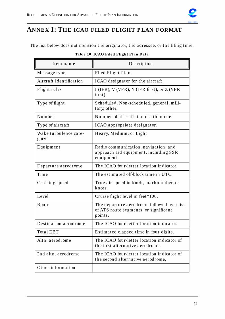
REQUIREMENTSDEFINITION FORADVANCED FLIGHT PLAN INFORMATION
74
EUROCONTROL
ANNEX I: THE ICAO FILED FLIGHT PLAN FORMAT
The list below does not mention the originator, the adressee, or the filing time.
Table 10: ICAO Filed Flight Plan Data
Item name Description
Message type Filed Flight Plan
Aircraft Identification ICAO designator for the aircraft.
Flight rules I (IFR), V (VFR), Y (IFR first), or Z (VFRfirst)
Type of flight Scheduled, Non-scheduled, general, mili-tary, other.
Number Number of aircraft, if more than one.
Type of aircraft ICAO appropriate designator.
Wake turbulence cate-gory
Heavy, Medium, or Light
Equipment Radio communication, navigation, andapproach aid equipment, including SSRequipment.
Departure aerodrome The ICAO four-letter location indicator.
Time The estimated off-block time in UTC.
Cruising speed True air speed in km/h, machnumber, orknots.
Level Cruise flight level in feet*100.
Route The departure aerodrome followed by a listof ATS route segments, or significantpoints.
Destination aerodrome The ICAO four-letter location indicator.
Total EET Estimated elapsed time in four digits.
Altn. aerodrome The ICAO four-letter location indicator ofthe first alternative aerodrome.
2nd altn. aerodrome The ICAO four-letter location indicator ofthe second alternative aerodrome.
Other information
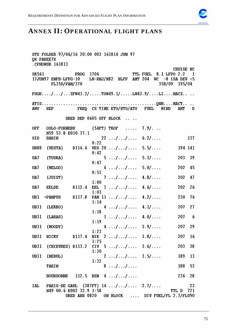
REQUIREMENTSDEFINITION FORADVANCED FLIGHT PLAN INFORMATION
75
EUROCONTROL
ANNEX II: OPERATIONAL FLIGHT PLANS
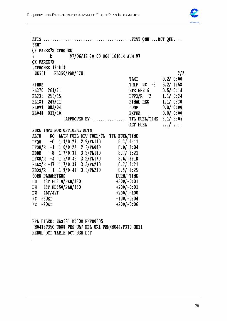
REQUIREMENTSDEFINITION FORADVANCED FLIGHT PLAN INFORMATION
76
EUROCONTROL
REQUIREMENTSDEFINITION FORADVANCED FLIGHT PLAN INFORMATION
77
EUROCONTROL
The previous two pages show a sample operational flight plan from Scandina-
vian Airlines (SAS). This OFPL contains the following items that are of interest:
• Flightnumber: ‘SK561’ callsign of the aircraft.
• Date: ‘17JUN97’ date of flight.
• City Pair: ‘ENFB-LFPG’ departure and arrival airport in ICAO code.
• Registration: ‘LN-RMJ’ aircraft registration.
• Type: ‘M82’ aircraft type (MD 82).
• ISA DEV: ‘+5’ deviation from international standard atmosphere.
• FL: ‘350’ planned cruise flight level in feet * 100.
• ZFW: ‘41.2’ zero fuel weight in kg *1000.
• TOW: ‘49.1’ take-off weight in kg *1000.
• LW: ‘43.9’ landing weight in kg *1000.
• SKED DEP: ‘0605’ scheduled departure time in UTC.
• SKED ARR: ‘0820’ scheduled arrival time in UTC.
• AWY: ‘UB31’ name of an airway.
• REP: ‘BOURSONNE’ name of a radar beacon or a reporting point.
• FREQ: ‘D117.8’ radar frequency emitted by a beacon.
• TIME: ‘22’ - ‘0:22’ total time since take-off in hours:minutes, and in between
beacons.
• FUEL: ‘7.9’ remaining fuel in tons.
• WIND: wind heading in degrees and magnitude in knots.
• AMT: ‘194’ magnetic track.
• D: ‘137’ distance between waypoints in nautical miles.
• TTL D: ‘721’ total distance flown in nautical miles.
• WINDS: ‘FL370 261/21’ wind information in knots/heading for different flight
levels.
• RPL FILED: information about a repetitive flight plan.
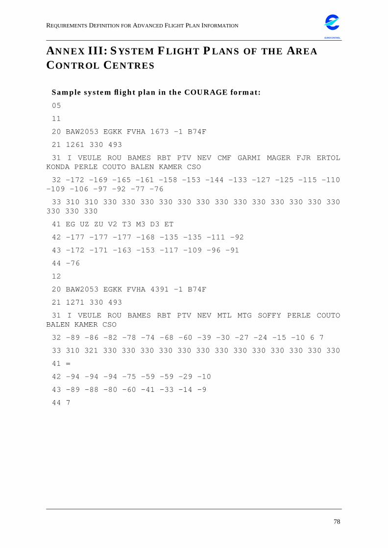
REQUIREMENTSDEFINITION FORADVANCED FLIGHT PLAN INFORMATION
78
EUROCONTROL
ANNEX III: SYSTEM FLIGHT PLANS OF THE AREACONTROL CENTRES
Sample system flight plan in the COURAGE format:
05
11
20 BAW2053 EGKK FVHA 1673 -1 B74F
21 1261 330 493
31 I VEULE ROU BAMES RBT PTV NEV CMF GARMI MAGER FJR ERTOLKONDA PERLE COUTO BALEN KAMER CSO
32 -172 -169 -165 -161 -158 -153 -144 -133 -127 -125 -115 -110-109 -106 -97 -92 -77 -76
33 310 310 330 330 330 330 330 330 330 330 330 330 330 330 330330 330 330
41 EG UZ ZU V2 T3 M3 D3 ET
42 -177 -177 -177 -168 -135 -135 -111 -92
43 -172 -171 -163 -153 -117 -109 -96 -91
44 -76
12
20 BAW2053 EGKK FVHA 4391 -1 B74F
21 1271 330 493
31 I VEULE ROU BAMES RBT PTV NEV MTL MTG SOFFY PERLE COUTOBALEN KAMER CSO
32 -89 -86 -82 -78 -74 -68 -60 -39 -30 -27 -24 -15 -10 6 7
33 310 321 330 330 330 330 330 330 330 330 330 330 330 330 330
41 =
42 -94 -94 -94 -75 -59 -59 -29 -10
43 -89 -88 -80 -60 -41 -33 -14 -9
44 7
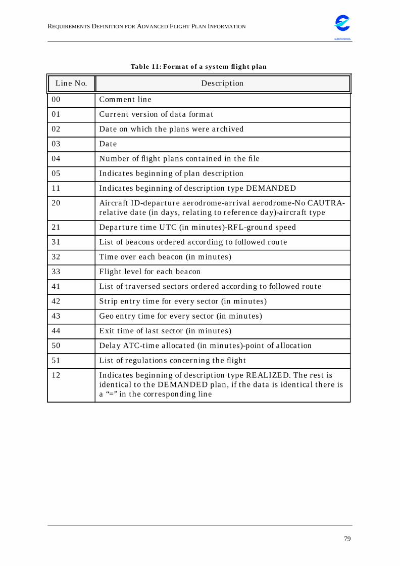
REQUIREMENTSDEFINITION FORADVANCED FLIGHT PLAN INFORMATION
79
EUROCONTROL
Table 11: Format of a system flight plan
Line No. Description
00 Comment line
01 Current version of data format
02 Date on which the plans were archived
03 Date
04 Number of flight plans contained in the file
05 Indicates beginning of plan description
11 Indicates beginning of description type DEMANDED
20 Aircraft ID-departure aerodrome-arrival aerodrome-No CAUTRA-relative date (in days, relating to reference day)-aircraft type
21 Departure time UTC (in minutes)-RFL-ground speed
31 List of beacons ordered according to followed route
32 Time over each beacon (in minutes)
33 Flight level for each beacon
41 List of traversed sectors ordered according to followed route
42 Strip entry time for every sector (in minutes)
43 Geo entry time for every sector (in minutes)
44 Exit time of last sector (in minutes)
50 Delay ATC-time allocated (in minutes)-point of allocation
51 List of regulations concerning the flight
12 Indicates beginning of description type REALIZED. The rest isidentical to the DEMANDED plan, if the data is identical there isa “=” in the corresponding line
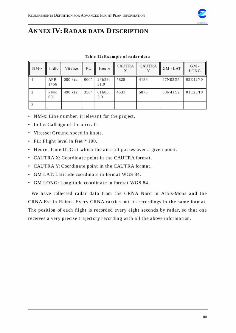
REQUIREMENTSDEFINITION FORADVANCED FLIGHT PLAN INFORMATION
80
EUROCONTROL
ANNEX IV: RADAR DATA DESCRIPTION
• NM-x: Line number; irrelevant for the project.
• Indic: Callsign of the aircraft.
• Vitesse: Ground speed in knots.
• FL: Flight level in feet * 100.
• Heure: Time UTC at which the aircraft passes over a given point.
• CAUTRA X: Coordinate point in the CAUTRA format.
• CAUTRA Y: Coordinate point in the CAUTRA format.
• GM LAT: Latitude coordinate in format WGS 84.
• GM LONG: Longitude coordinate in format WGS 84.
We have collected radar data from the CRNA Nord in Athis-Mons and the
CRNA Est in Reims. Every CRNA carries out its recordings in the same format.
The position of each flight is recorded every eight seconds by radar, so that one
receives a very precise trajectory recording with all the above information.
Table 12: Example of radar data
NM-x indic Vitesse FL Heure CAUTRAX
CAUTRAY GM - LAT GM -
LONG
1 AFR1466
000 kts 000’ 23h59:31.0
5828 4186 47N03’55 05E12’30
2 PNR601
490 kts 350’ 01h06:3.0
4531 5875 50N41’52 01E25’10
3
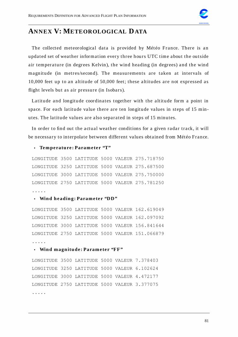
REQUIREMENTSDEFINITION FORADVANCED FLIGHT PLAN INFORMATION
81
EUROCONTROL
ANNEX V: METEOROLOGICAL DATA
The collected meteorological data is provided by Météo France. There is an
updated set of weather information every three hours UTC time about the outside
air temperature (in degrees Kelvin), the wind heading (in degrees) and the wind
magnitude (in metres/second). The measurements are taken at intervals of
10,000 feet up to an altitude of 50,000 feet; these altitudes are not expressed as
flight levels but as air pressure (in Isobars).
Latitude and longitude coordinates together with the altitude form a point in
space. For each latitude value there are ten longitude values in steps of 15 min-
utes. The latitude values are also separated in steps of 15 minutes.
In order to find out the actual weather conditions for a given radar track, it will
be necessary to interpolate between different values obtained from Météo France.
• Temperature: Parameter “T”
LONGITUDE 3500 LATITUDE 5000 VALEUR 275.718750
LONGITUDE 3250 LATITUDE 5000 VALEUR 275.687500
LONGITUDE 3000 LATITUDE 5000 VALEUR 275.750000
LONGITUDE 2750 LATITUDE 5000 VALEUR 275.781250
.....
• Wind heading: Parameter “DD”
LONGITUDE 3500 LATITUDE 5000 VALEUR 162.619049
LONGITUDE 3250 LATITUDE 5000 VALEUR 162.097092
LONGITUDE 3000 LATITUDE 5000 VALEUR 156.841644
LONGITUDE 2750 LATITUDE 5000 VALEUR 151.066879
.....
• Wind magnitude: Parameter “FF”
LONGITUDE 3500 LATITUDE 5000 VALEUR 7.378403
LONGITUDE 3250 LATITUDE 5000 VALEUR 6.102624
LONGITUDE 3000 LATITUDE 5000 VALEUR 4.472177
LONGITUDE 2750 LATITUDE 5000 VALEUR 3.377075
.....
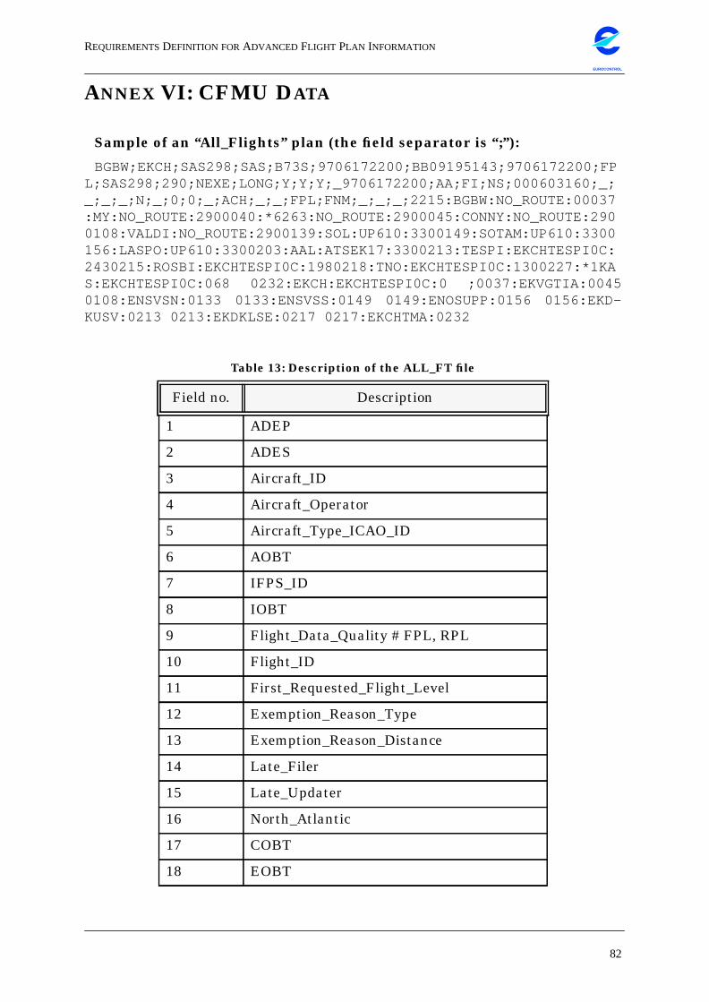
REQUIREMENTSDEFINITION FORADVANCED FLIGHT PLAN INFORMATION
82
EUROCONTROL
ANNEX VI: CFMU DATA
Sample of an “All_Flights” plan (the field separator is “;”):
BGBW;EKCH;SAS298;SAS;B73S;9706172200;BB09195143;9706172200;FPL;SAS298;290;NEXE;LONG;Y;Y;Y;_9706172200;AA;FI;NS;000603160;_;_;_;_;N;_;0;0;_;ACH;_;_;FPL;FNM;_;_;_;2215:BGBW:NO_ROUTE:00037:MY:NO_ROUTE:2900040:*6263:NO_ROUTE:2900045:CONNY:NO_ROUTE:2900108:VALDI:NO_ROUTE:2900139:SOL:UP610:3300149:SOTAM:UP610:3300156:LASPO:UP610:3300203:AAL:ATSEK17:3300213:TESPI:EKCHTESPI0C:2430215:ROSBI:EKCHTESPI0C:1980218:TNO:EKCHTESPI0C:1300227:*1KAS:EKCHTESPI0C:068 0232:EKCH:EKCHTESPI0C:0 ;0037:EKVGTIA:00450108:ENSVSN:0133 0133:ENSVSS:0149 0149:ENOSUPP:0156 0156:EKD-KUSV:0213 0213:EKDKLSE:0217 0217:EKCHTMA:0232
Table 13: Description of the ALL_FT file
Field no. Description
1 ADEP
2 ADES
3 Aircraft_ID
4 Aircraft_Operator
5 Aircraft_Type_ICAO_ID
6 AOBT
7 IFPS_ID
8 IOBT
9 Flight_Data_Quality # FPL, RPL
10 Flight_ID
11 First_Requested_Flight_Level
12 Exemption_Reason_Type
13 Exemption_Reason_Distance
14 Late_Filer
15 Late_Updater
16 North_Atlantic
17 COBT
18 EOBT
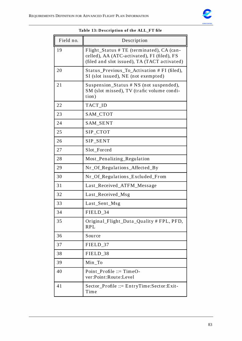
REQUIREMENTSDEFINITION FORADVANCED FLIGHT PLAN INFORMATION
83
EUROCONTROL
19 Flight_Status # TE (terminated), CA (can-celled), AA (ATC-activated), FI (filed), FS(filed and slot issued), TA (TACT activated)
20 Status_Previous_To_Activation # FI (filed),SI (slot issued), NE (not exempted)
21 Suspension_Status # NS (not suspended),SM (slot missed), TV (trafic volume condi-tion)
22 TACT_ID
23 SAM_CTOT
24 SAM_SENT
25 SIP_CTOT
26 SIP_SENT
27 Slot_Forced
28 Most_Penalizing_Regulation
29 Nr_Of_Regulations_Affected_By
30 Nr_Of_Regulations_Excluded_From
31 Last_Received_ATFM_Message
32 Last_Received_Msg
33 Last_Sent_Msg
34 FIELD_34
35 Original_Flight_Data_Quality # FPL, PFD,RPL
36 Source
37 FIELD_37
38 FIELD_38
39 Min_To
40 Point_Profile ::= TimeO-ver:Point:Route:Level
41 Sector_Profile ::= EntryTime:Sector:Exit-Time
Table 13: Description of the ALL_FT file
Field no. Description
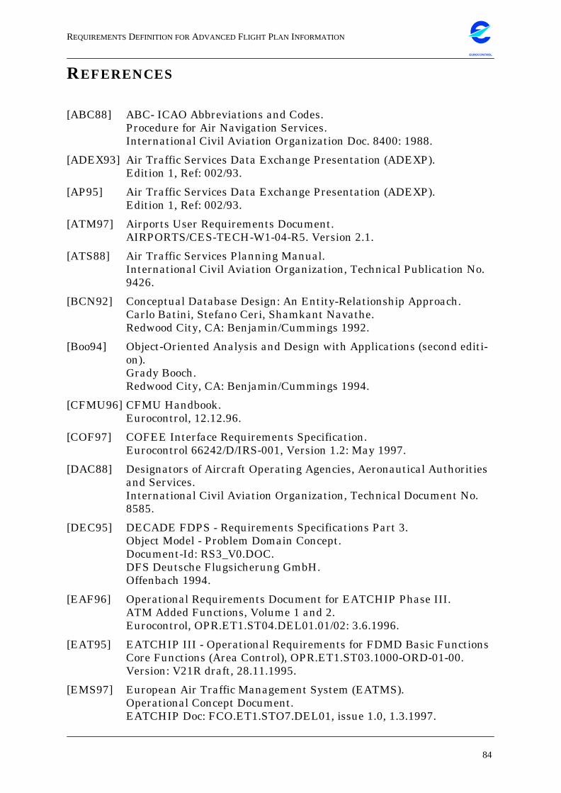
REQUIREMENTSDEFINITION FORADVANCED FLIGHT PLAN INFORMATION
84
EUROCONTROL
REFERENCES
[ABC88] ABC- ICAO Abbreviations and Codes.Procedure for Air Navigation Services.International Civil Aviation Organization Doc. 8400: 1988.
[ADEX93] Air Traffic Services Data Exchange Presentation (ADEXP).Edition 1, Ref: 002/93.
[AP95] Air Traffic Services Data Exchange Presentation (ADEXP).Edition 1, Ref: 002/93.
[ATM97] Airports User Requirements Document.AIRPORTS/CES-TECH-W1-04-R5. Version 2.1.
[ATS88] Air Traffic Services Planning Manual.International Civil Aviation Organization, Technical Publication No.9426.
[BCN92] Conceptual Database Design: An Entity-Relationship Approach.Carlo Batini, Stefano Ceri, Shamkant Navathe.Redwood City, CA: Benjamin/Cummings 1992.
[Boo94] Object-Oriented Analysis and Design with Applications (second editi-on).Grady Booch.Redwood City, CA: Benjamin/Cummings 1994.
[CFMU96] CFMU Handbook.Eurocontrol, 12.12.96.
[COF97] COFEE Interface Requirements Specification.Eurocontrol 66242/D/IRS-001, Version 1.2: May 1997.
[DAC88] Designators of Aircraft Operating Agencies, Aeronautical Authoritiesand Services.International Civil Aviation Organization, Technical Document No.8585.
[DEC95] DECADE FDPS - Requirements Specifications Part 3.Object Model - Problem Domain Concept.Document-Id: RS3_V0.DOC.DFS Deutsche Flugsicherung GmbH.Offenbach 1994.
[EAF96] Operational Requirements Document for EATCHIP Phase III.ATM Added Functions, Volume 1 and 2.Eurocontrol, OPR.ET1.ST04.DEL01.01/02: 3.6.1996.
[EAT95] EATCHIP III - Operational Requirements for FDMD Basic FunctionsCore Functions (Area Control), OPR.ET1.ST03.1000-ORD-01-00.Version: V21R draft, 28.11.1995.
[EMS97] European Air Traffic Management System (EATMS).Operational Concept Document.EATCHIP Doc: FCO.ET1.STO7.DEL01, issue 1.0, 1.3.1997.
REQUIREMENTSDEFINITION FORADVANCED FLIGHT PLAN INFORMATION
85
EUROCONTROL
[EN94] Fundamentals of Database Systems (second edition).Ramez Elmasri, Shamkant Navathe.Redwood City, CA: Benjamin/Cummings 1994.
[FDP97] Operational Requirements for Flight Data Processing and DistributionCore Functions (Area Control), OPR.ET1.ST03.1000-ORD-01-00.Eurocontrol, 21.1.97.
[FMS95] Integrating Flight Management System Data into Air Traffic Control.EEC Note 28/95, EEC Task AS09, EATCHIP Task FCO/ET1/ST10.Eurocontrol, Dec. 1995.
[GHJ+95] Design Patterns: Elements of Reusable Object-Oriented Software.Erich Gamma, Richard Helm, Ralph Johnson, John Vlissides.Menlo Park, CA: Addison-Wesley 1995.
[ICAO85] Rules of the Air and Air Traffic Services - 12th ed.Doc. 4444-RAC/501/12.International Civil Aviation Orginzation.Montreal Quebec 1985.
[ILex85] ICAO LexiconInternational Civil Aviation Organization, General PublicationICAO Document No. 9794.Montreal Quebec 1985.
[ISST97] Modelling Guidelines for Object-Oriented Analysis.ISST Report 4/97, Edition 1.0: 14.4.97.
[JCJ+92] Object-Oriented Software Engineering - A Use Case Driven Approach.Ivar Jacobson, Magnus Christerson, Patrik Jonsson, Gunnar Över-gaard.Addison Wesley.Wokingham England 1992.
[OBM97] "Business Components for End-User Assembly" by Greg Baster.In: Object Magazine, January 1997 issue.
[OOA97] Object Oriented Analysis for Advanced Flight Data Management.Eurocontrol, EEC Report No. 306, March 1997.
[OLDI95] EUROCONTROL Standard for On-Line Data InterchangeDraft 1.4P. M. Bailey, Work Program Manager DED-2.EUROCONTROL DPS-ET1-ST06-STD-01-00.EUROCONTROLEATCHIP Planning Division96, Rue de la FuséeB-1130 Bruxelles
[OHE96] The Essential Distributed Objects Survival Guide.Robert Orfali, Dan Harkey, Jeri Edwards.New York City, NY: John Wiley&Sons, Inc. 1996.
REQUIREMENTSDEFINITION FORADVANCED FLIGHT PLAN INFORMATION
86
EUROCONTROL
[PID96] Pilot Information Description.Final Report DRA/LS1(ATC)/PID/CR/002-003-004.Eurocontrol EATCHIP: 7.10.97.
[Pri96] Developing Business Objects.A Framework Driven Approach.Robert Prins.Maidenhead, Berkshire, England: McGraw-Hill 1996.
[RBP+91] Object-Oriented Modelling & Design.J. Rumbaugh, M. Blaha, W. Premerlani, F. Eddy and W. Lorensen.Prentice Hall Englewood Cliffs 1991.
[RTCA95] Report of the RTCA Board of Directors’ Select Committee on FreeFlight.January 1995.
[Sch91] Lexikon der Informatik und Datenverarbeitung (3. Aufl.).Hans-Jochen Schneider (Hrsg.).München: R. Oldenbourg Verlag, 1991.
[Sim94] Business Objects - Delivering Cooperative Objects for Client-Server.Oliver Sims.Maidenhead, Berkshire, England: McGraw-Hill, 1994.
[WCS96] Programming Perl (second edition).Larry Wall, Tom Christiansen, Randal L. Schwartz.Sebastopol, CA: O’Reilly&Ass. 1996.
[YWT+95] Mainstream Objects: An Analysis and Design Approach for Business.Ed Yourdan, Katherine Whitehead, Jim Thomann, Karin Oppel, PeterNevermann.Upper Saddle River, NJ: Prentice Hall, 1995.
REQUIREMENTSDEFINITION FORADVANCED FLIGHT PLAN INFORMATION
87
EUROCONTROL
GLOSSARY
ACC Area Control Centre, a unit established to provide air trafficcontrol service to controlled flights in control areas under itsjurisdiction.
Active view A view which is linked to the underlying objects such thatattributes and relationships represented in the view arekept up-to-date with the states of the underlying objects.
Aggregation A data abstraction which allows a relationship betweennamed objects to be thought of as a (higher-level) namedobject. Aggregation is the concurrence of a certain amountof characteristics into an object-type which can be referredto without having to refer to its components, but can bedecomposed into the instances of the component objects.
AFTN Aeronautical Fixed Telecommunications Network is thestandard communication network, based on teletypewritertechnology. AFTN will be replaced by ATN in the comingyears.
Aircraft Any machine that can derive support in the atmospherefrom the reactions of the air other than reactions of the airagainst the earth’s surface.
Airway A control area, or portion thereof, established in the form ofa corridor equipped with radio navigational aids.
Altitude The vertical distance of a level, a point or an object consid-ered as a point, measured from mean sea level.
Application com-ponents
Manifestation of business objects within the context of theBusiness Object Facility.
ATFM Air Traffic Flow Management is the process of regulatinghow many planes are in the system, while ensuring an opti-mum flow of traffic by preventing overload situations inATC centres.
ATM The term used to describe the total system, ground and air,needed to ensure the safe and efficient movement of air-craft, in all phases of operation. It covers airborne equip-ment (such as FMS) and the ATC systems; ATFM providesmanagement and control of air traffic, both in the air and onthe ground. Besides Air Traffic Control, ATM comprises AirTraffic Flow Management (ATFM) and Airspace manage-ment (ASM).
REQUIREMENTSDEFINITION FORADVANCED FLIGHT PLAN INFORMATION
88
EUROCONTROL
ATN Aeronautical Telecommunication Network, as successor ofATFN will soon be the future basic communication facilityin aeronautics.
Atomic Non-decomposable.
ATS Air Traffic Services, a generic term meaning variously, flightinformation service, alerting service, air traffic advisory ser-vice, air traffic control service, area control service,approach control service or aerodrome control service.
Attribute Describes a single, static property of an object and does nothave an existence independently of the object.
BADA Base of Aircraft DAta. Developed by J.L. Renteux at theHeadquarters of EUROCONTROL, it supplies operationaldata about the performance of aircraft types, at the momenteven taking into account the way different airlines use theaircraft types resulting in different performance values. Theway it does this is by using a set of equations driven by coef-ficients for each aircraft type. The input is the environmentof the aircraft, such as air pressure, speed and so on, andthe ouput is data responding to the input.
Business Object A representation of a thing active in the business domain,including at least its business name and definition,attributes, behaviour, relationships, rules, policies, and con-straints. A BO may represent for example a person, place,event, business process or concept. Typical examples of BOsare: employee, product, invoice and payment.
Business ObjectFacility
The infrastructure (application architecture, services, etc.)required to support business objects operating as coopera-tive application components in a distributed object environ-ment.
Cardinality The number of instances that participate in a relation.
CAUTRA (Automatic Air Traffic coordinator) French ATC system.
CFMU The Central Flow Management Unit establishes regulationsin congested airspace by providing central Slot Allocationwithin the ECAC member states. Its major objective is tocut peaks in sector load, minimize Holding Pattern andshare delays on a fair basis.
REQUIREMENTSDEFINITION FORADVANCED FLIGHT PLAN INFORMATION
89
EUROCONTROL
CommonBusiness Object
An object representing those business semantics that can beshown to be common across most businesses. CBOs aremodels, templates, designs and/or patterns which includethe necessary defined semantics for interaction. CBOs arealso runtime software constructs, and map without signifi-cant transformation to the design models.
Component Concept of specialized, application-independent, encapsu-lated, unit of functionality.
Constraints Rules defining static and dynamic application propertiesthat are not conveniently expressed using the object andoperation features of a data model.
Database A collection of related data under control of a database man-agement system (DBMS).
Data model A term used in a variety of situations in connection withdata storage at either a logical or physical level but usuallythe former. It normally implies a formally defined structurewithin which the data may be represented.
DBMS DataBase Management system, a software system for theuse and control of databases.
Elevation The vertical distance of a point or a level, on or affixed to thesurface of the earth, measured from mean sea level.
Entity A thing of significance, whether real or imagined, aboutwhich information needs to be known or held. A differentword for ‘object’ or ‘object-type’, often used in connectionwith Entity-Relationship modelling.
FDPS Flight Data Processing System.
FlightManagementSystem
Flight Management Systems (FMS) are part of the on-boardcomputer equipment of modern aircraft. FMS guides an air-craft on its trajectory using information on weather,engines, Flight PLan and position.
Flight Plan Specified information provided to air traffic services units,relative to an intended flight or portion of a flight of an air-craft.
Flow Control Measures designed to adjust the flow of traffic into a givenroute, or bound for a given aerodrome, so as to ensure themost effective utilization of the airspace.
Foreign key A unique identifier in a table that is imported from anothertable.
REQUIREMENTSDEFINITION FORADVANCED FLIGHT PLAN INFORMATION
90
EUROCONTROL
FPL Filed flight plan, the flight plan as filed with an ATS Unit bythe pilot or his designated representative, without any sub-sequent change.
Gate-to-gateservice
Starts at the moment when the user first interacts withATC and ending with the switch-off of the engines. It alsoincludes the process of charging users for ATM services.
Generalization A data abstraction which enables a class of individualobjects to be thought of generically as a single named object.Generalization is the creation of a generic object when simi-lar characteristics of different object-types are recognizedand grouped together to form the generic type. In the spe-cializations the different properties of the disjunct special-izations can be found.
Hierarchy A ranking or ordering of abstractions.
Initial FlightPlan, InitialFlight planProcessingSystem
The Initial Flight plan Processing System is used to correct/complete FPL. Corrected data will afterwards be sent to allATC authorities along the route and will be fed in the TACTsystem as Initial Flight Plan (IFPL).
IFR Instrumental flight rules, a set of rules governing the con-duct of flight under instrumental meteorological conditions.
Instance One (composed) element of data from one object type. Also:database instance. The data in a database at a particularmoment in time. Something you can do things to. A singlereal world thing.
Metadata Executable form of business object information representa-tion. This may include: constraints, rules, roles, policies,relationships, states, attributes, visibility, dependencies,protocols, pre- and post-conditions, error conditions, warn-ing conditions, or events.
MTCD Medium Term Conflict Detection.
New-Age FlightPlan
The envisioned future flight plan to be filed by most air-space users in the US when ATC-AOC informationexchange is fully implemented. It will be based on the ICAOflight plan, but with additional information on airline prior-ities and preferences.
REQUIREMENTSDEFINITION FORADVANCED FLIGHT PLAN INFORMATION
91
EUROCONTROL
Normalization A step by step process that produces relational definitionsthat have:- no repeating groups- the same kind of values assigned to attributes or columns- a distinct name- distinct and uniquely identifiable rows.
Objects All concrete facts, and abstractions thereof, which need tobe distinguished in an information system.
Object type An abstraction of a group of similar objects in the realworld, including the typical characteristics of this group(also called ‘data types’).
Path The way an aircraft flies expressed in three dimensions.
Planned FlightData (PFD)
All flights published in the OAG are known as PlannedFlight Data within the CFMU context and only contain theserved city pair, i.e. no route information is provided.
Point Any geographical location on the surface of the earth usedby any aspect of aviation.
Pre-TacticalPhasePre-Tacticalsystem
Uses FPL data and statistical data to establish ANM.
Primary Key The attribute in a relational table which uniquely identifiesthe table tuples.
Primary Radar A radar system which uses reflected radio signals.
Profile The orthogonal projection of a flight path or the portionthereof on the vertical surface containing the nominal track.
Query A command given to the DBMS to search for specific data,and return it in table formats.
Redundancy When the same data is represented in more than one placeand/or way.
Reflection Ability of a system to analyze and report its state and activ-ities and to alter them based on this analysis.
Repetitive FlightPlan (RPL)
A Repetitive Flight Plan is published by a operational car-rier, announcing the served city pair, the preferred route,flight levels and the frequency of flights, i.e. every Monday& Friday.
REQUIREMENTSDEFINITION FORADVANCED FLIGHT PLAN INFORMATION
92
EUROCONTROL
Route A planned way to fly between points.
Slot Allocation /Slot AllocationMessage
The term Slot Allocation refers to the Calculated Take-OffTime (CTOT) slot for a given flight and is sent to every regu-lated flight and all relevant ATC authorities along the routeby the CFMU.
Strategic ATCconstraint
Generated by airspace structure and organization of ATC.
Strategic System As part of the CFMU Strategic System is used to calculatesector workloads on a mid-term basis (6 month - 48h).
Surveillance The representation of the measurement of an aircraft’spresent position independently of navigational positionsources aboard the aircraft.
System FlightPlan (SFPL)
This is the FDPS internal representation of the flight planresulting from the Initial Flight Plan Processing. The SFPLsupports the real-time control of the flight and stores theflight intentions for a given aircraft during the flightprogress.
Tactical ATCconstraint
These constraints represent controllers’ actions, guidanceorders, or clearances. They are divided into complete/incom-plete constraints.
Tactical System The Tactical System as is used for centralized Slot Alloca-tion within the CFMU.
TMA A control area normally established at the confluence ofATS routes in the vicinity of one or more major aerodromes.
Track The projection on the earth’s surface of the path of an air-craft, the direction of which path at any point is usuallyexpressed in degrees from North (true, magnetic or grid)(ICAO).
Trajectory The way an aircraft flies expressed in three dimensions,plus time over the locations sampled.
View A simplified representation that excludes some attributes,relationships and operations, and also flattens a complexstructure. Insulates individual applications from evolution-ary changes in the enterprise model.


![EUROCONTROL EXPERIMENTAL CENTRE · EUROCONTROL EXPERIMENTAL CENTRE ... EEC Note No. 13/05 ... [20] Guldenmund, F.W. (2000) The Nature of Safety Culture: a review of theory and research](https://img.pdfslide.net/doc/110x75/5b258e827f8b9acc7f8b4582/eurocontrol-experimental-centre-eurocontrol-experimental-centre-eec-note.jpg)