Embed Size (px)
Citation preview
Evaluation of Gaming Environments for Mixed
Reality Interfaces and Human Supervisory Control
in Telerobotics
Ida Bagus Kerthyayana Manuaba
April 2014
A thesis submitted for the degree of Doctor of Philosophy
of the Australian National University
Research School of Computer Science
College of Engineering and Computer Science
The Australian National University

ii
iii
Declaration
This thesis contains the results of my own original research and has not been submitted for a
postgraduate degree at any university or institution, except where specific reference or
acknowledgment is made to the work or contribution of others. Much of this content research
has either been published or submitted for publication as conference and journal proceedings,
short paper, workshop presentation, poster, and exhibition. The following is a list of these
publications:
Paper conference and journal proceedings:
I.B.K. Manuaba, K. Taylor, & T. Gedeon (2012): ―Evaluation of Response Models to a
Series of Commands in a Telerobotics Supervisory Control System‖. In the proceedings of
the 5th International Conference on Intelligent Robotics and Applications. Montreal,
Quebec, Canada, October, 2012, LCNS 7508, Springer, Part III, pp. 73-84.
I.B.K. Manuaba, K. Taylor, & E. Widzyk-Capehart (2011): ―Building Effective
Telerobotics Interfaces For Mining Applications by Utilising Mixed Reality‖. In the
proceedings of 22nd International World Mining Congress and Expo. Istanbul, Turkey,
September, 2011, pp. 387-394.
I.B.K. Manuaba, K. Taylor, & T. Gedeon (2011): ―Exploration of Mixed Reality
Environment for Telerobotics Interface: An Option to Provide Effective Information‖. In
the proceedings of the Australian Journal of Intelligent Information Processing Systems,
Special issue for the International Workshop on Bio-inspired Computing for Intelligent
Environments and Logistic Systems (IWBCIELS2011), Vol 13, No.1, 2011, pp. 31-38.
I.B.K. Manuaba, K. Taylor, & T. Gedeon (2011): ―Comparison between Two Mixed
Reality Environments for Telerobotics Interface‖. In the proceedings of the IEEE
International Conference on Robotics and Automation (ICRA2011). Shanghai, China,
May, 2011, pp. 1335-1340.
I.B.K. Manuaba, K. Taylor, & T. Gedeon (2010): ―Exploration of Second Life as a
Virtual Gaming Environment for Telerobotics‖. In the proceedings of the International
Conference of Asian Pacific Computer Human Interaction (APCHI2010). Sanur-Bali,
Indonesia, July, 2010, pp. 674-679.
iv
Short Paper:
I.B.K. Manuaba (2011): ―Applying a Mixed Reality Interface with Human Supervisory
Control for Telerobotics‖. In Science and Engineering Expo Graduate Research 2011.
CSIRO ICT Centre, Canberra, Australia, August 2011, pp. 7-8.
I.B.K. Manuaba, K. Taylor, T. Gedeon, & E. Widzyk-Capehart (2010): ―Evaluation of
Augmented Virtuality Environments for Telerobotics Interface‖. In CSIRO ICTCC‘10,
Sydney, 10 – 11 November 2010.
Workshops Presentations:
I.B.K. Manuaba (2011): ―Applying a Mixed Reality Interface with Human Supervisory
Control for Telerobotics‖. In Science and Engineering Expo Graduate Research 2011.
CSIRO ICT Centre, Canberra, Australia, August 2011.
I.B.K. Manuaba, K. Taylor, & T. Gedeon (2011): ―Exploration of Mixed Reality
Environment for Telerobotics Interface: An Option to Provide Effective Information‖. In
the International Workshop on Bio-inspired Computing for Intelligent Environments and
Logistic Systems (IWBCIELS2011). The Australian National University, Canberra,
Australia, March 2011.
K. Taylor, & I.B.K. Manuaba, I.B.K. (2010): ―Using computer gaming environments to
develop situated virtual reality methods for telerobotics of mining equipment‖. In OzViz
2010, Queensland Bioscience Precinct, University of Queensland, 2 December 2010.
Posters:
I.B.K. Manuaba (2010): ―Applying a Predictive Display in a Mixed Reality Interface for a
Tele-Manipulator‖. In ANU Poster Day CECS, The Australian National University,
Canberra, Australia, 15 August 2011.
I.B.K. Manuaba, K. Taylor, T. Gedeon, & E. Widzyk-Capehart (2010): ―Comparison Two
Augmented Virtuality Environments for Telerobotics Interface‖. In CSIRO ICTCC‘10,
Sydney, 10 – 11 November 2010.
I.B.K. Manuaba (2010): ―Play with the Robot Arm with Your Avatar…No Worries!!
Using 3D virtual gaming with Mixed Reality Framework to control the robot arm in a
remote location‖. In ANU Poster Day CECS, The Australian National University,
Canberra, Australia, 22 July 2010.
v
Exhibition:
Exhibition at CSIRO Discovery Centre: A prototype of telerobotics system as a
model application for remote manipulation in simple mining scenario by utilising
the principles of human supervisory control in mixed reality interfaces. (2011 –
Today)
The research presented in this thesis has been performed under the supervisor of Dr. Ken
Taylor and Prof. Tom Gedeon, and using some implementation work done by Mr. Stephane
Bersot.
Ida Bagus Kerthyayana Manuaba
The Australian National University
April 2014

vi

vii
To my beloved Family and Friends.

viii
ix
Acknowledgment
Over the past three and a half years of my research, I have received support, guidance and
encouragement from a great number of individuals whom I would like to acknowledge and
thank.
First and foremost, to my God, Ida Sang Hyang Widi Wasa, I am thankful for the faith,
grace and mercy bestowed upon me during my studies.
I would like to thank my supervisory panel, Dr. Ken Taylor, Prof. Tom Gedeon and
Assoc. Prof. Henry Gardner for their guidance, insight, inspiration, feedback, and
encouragement. Special thanks go to Ken Taylor for his patience, helpfulness and support. This
thesis would certainly not have been possible without his role as my supervisor. Thanks also to
Tom Gedeon for his support, advice and encouragement, which was always available when I
needed it.
To the Commonwealth Scientific and Industrial Research Organisation (CSIRO), I am
grateful for the scholarship awards and research facilities. I am grateful also to the Research
School of Computer Sciences (RSCS) for the additional financial support and facilities.
I thank my father, Ida Bagus Putra; my mother, Ida Ayu Made Puspawati; and my sister,
Ida Ayu Putu Suryanti, as well as all my family in Bali for providing me their love, support and
blessings. Special thanks also goes to Yodi Christiani for her support, helpfulness and patience;
especially in reading most of my work, discussing and analysing my experimental data, and
teaching me about many other things. I thank Simon Ow, Lauren O‘Neil, Wayan Arka and
family, and Meksi Ndii for their helpfulness, support and patience in proofreading my writing,
especially for this thesis; Adi Swandani for her support and helpfulness and for never
complaining when I needed her help, even in the middle of the night; Ida Bagus Rajendra and
family for their support in helping me start my research study.
I thank the CSIRO and ANU-RSCS fellows and administrators: Chris Gunn, Doug
Palmer, Matt Adcock, Dingyun Zhu, Stephane Bersot, Umran Abdulla, Renate Hays, Deirdre
Tribe, Karen Barndt, Bruce Daphne, Julie Arnold, Shaw Tyi Tan, Suzy Andrew, and many
others who would take up over a page if mentioned individually, for being friendly and helping
me during my study.
Considerable thanks also to all the volunteers who participated in my experimental
studies for their time, participation and feedback, which made it possible for me to complete the
evaluation of my research.

x
Finally, I would like to thank all my friends in Australia, especially my housemates: Budi,
Momo, Adrian, Hanif, Agung, and Seti; the ANU iHcc group; the Robogals group, Discovery
Centre, PPIA, OUI, Indorunners and all my friends in Indonesia for their support during my
study.
xi
Glossary of Abbreviations
AJAX Asynchronous JavaScript and XML
ANU Australian National University
API Application Programming Interface
AR Augmented Reality
AV Augmented Virtuality
cdf cumulative distribution function
CPU Central Processing Unit
crv continuous random variables
CSIRO Commonwealth Scientific and Industrial Research
Organisation
DDX Dynamic Data eXchange
DOF Degree of Freedom
E Rijsbergen‘s effectiveness (Chapter 5)
FIFO First-In-First-Out
FS Full Stop
HSC Human Supervisory Control
HTTP The Hypertext Transfer Protocol
ICT Information and Communication Technology
xii
iHcc Information & Human Centred Computing
info Information
IP Internet Protocol
KB Kilo Bytes
LAN Local Area Network
LGPL Lesser General Public License
LiSA Localization and Semantics of Assistance
LSL Linden Scripting Language
MB Mega Bytes
MR Mixed Reality
OpenCV Open Source Computer Vision
OR Odd Ratio
P / p – value Probability Value
PC Personal Computer
PDA Personal Data Assistant
Pdf probability density function
PHP Hypertext Preprocessor
PPV Position Predictive Value
PTZ Pan Tilt Zoom
R number of requests (Chapter 6)
Chi-square goodness fit test
RAM Random Access Memory
xiii
ROM Read Only Memory
RPC Remote Procedure Call
SA Situational Awareness
SD Standard Deviation
Sec Seconds
SL Second Life
Sm Simmersion
T length of playing (Chapter 6)
TCP Transmission Control Protocol
TS Temporary Stop
TUI Telerobotics User Interfaces
UAV Unmanned Aerial Vehicle
UDP User Datagram Protocol
USAR Urban Search and Rescue
UWA University of Western Australia
VGA Video Graphic Array
VR Virtual Reality
VRML Virtual Reality Modelling Language
WEB Website
Chi-square / Chi-square goodness fit test
X3D Extensible 3D
xiv
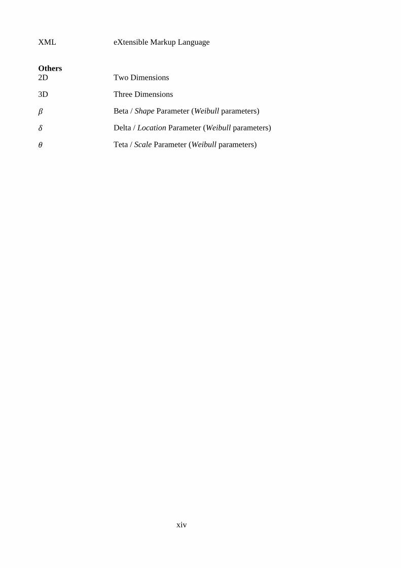
XML eXtensible Markup Language
Others 2D Two Dimensions
3D Three Dimensions
Beta / Shape Parameter (Weibull parameters)
Delta / Location Parameter (Weibull parameters)
Teta / Scale Parameter (Weibull parameters)
xv
Abstract
Telerobotics refers to a branch of technology that deals with controlling a robot from a distance.
It is commonly used to access difficult environments, reduce operating costs, and to improve
comfort and safety. However, difficulties have emerged in telerobotics development. Effective
telerobotics requires maximising operator performance and previous research has identified
issues which reduce operator performance, such as operator attention being divided across the
numerous custom built interfaces and continuous operator involvement in a high workload
situation potentially causing exhaustion and subsequent operator error.
This thesis evaluates mixed reality and human supervisory control concepts in a gaming
engine environment for telerobotics. This concept is proposed in order to improve the
effectiveness of current technology in telerobotic interfaces. Four experiments are reported in
this thesis which covers virtual gaming environments, mixed reality interfaces, and human
supervisory control and aims to advance telerobotics technology.
This thesis argues that gaming environments are useful for building telerobotic interfaces
and examines the properties required for telerobotics. A useful feature provided by gaming
environments is that of overlying video on virtual objects to support mixed reality interfaces.
Experiments in this thesis show that mixed reality interfaces provide useful information without
distracting the operator from the task.
This thesis introduces two response models based on the planning process of human
supervisory control: Adaptation and Queue response models. The experimental results show
superior user performance under these two response models compared to direct/manual control.
In the final experiment a large number of novice users, with a diversity of backgrounds, used a
robot arm to push blocks into a hole by using these two response models.
Further analyses on evaluating the user performance on the interfaces with two response
models were found to be well fitted by a Weibull distribution. Operators preferred the interface
with the Queue response model over the interface with the Adaptation response model, and
human supervisory control over direct/manual control.
It is expected that the increased sophistication of control commands in a production
system will usually be greater than those that were tested in this thesis, where limited time was
available for automation development. Where that is the case the increases in human
xvi
productivity using human supervisory control found in this experiment can be expected to be
greater.
The research conducted here has shown that mixed reality in gaming environments, when
combined with human supervisory control, offers a good route for overcoming limitations in
current telerobotics technology. Practical applications would benefit by the application of these
methods, making it possible for the operator to have the necessary information available in a
convenient and non-distracting form, considerably improving productivity.
xvii
Table of Contents
Declaration ................................................................................................................. iii
Acknowledgment ....................................................................................................... ix
Glossary of Abbreviations ........................................................................................ xi
Abstract ..................................................................................................................... xv
Table of Contents ................................................................................................... xvii
List of Figures ........................................................................................................ xxiii
List of Tables ......................................................................................................... xxix
Chapter 1 .................................................................................................................... 1
Introduction ................................................................................................................ 1
1.1 Telerobotics ............................................................................................................ 1
1.1.1 What is Telerobotics? .................................................................................. 1
1.1.2 Type of Telerobotics .................................................................................... 2
1.1.3 Human Factor in Telerobotics .................................................................... 5
1.1.4 Technology of Telerobotics ......................................................................... 7
1.2 Research Topic ....................................................................................................... 9
1.3 Research Outcomes .............................................................................................. 10
1.4 Contributions ........................................................................................................ 10
1.5 Research Design ................................................................................................... 11
1.5.1 Methodology .............................................................................................. 12
1.5.2 Research Framework, Variable and Instrument ........................................ 12
1.5.2.1 Research Framework .............................................................................. 13
1.5.2.2 Research Indicators ................................................................................. 16
1.5.3 Model Analysis. ......................................................................................... 17
1.5.4 Timeline and Places ................................................................................... 18
1.6 Organisation of the Dissertation........................................................................... 20
Chapter 2 .................................................................................................................. 23
Gaming Environments for Telerobotics User Interface ....................................... 23
2.1 Gaming Environment ........................................................................................... 23
2.1.1 Utilising Gaming Engines in Telerobotic Interfaces ................................. 23
2.1.2 Type of Gaming Platforms ........................................................................ 24
xviii
2.1.2.1 Second Life ............................................................................................. 24
2.1.2.2 Mycosm .................................................................................................. 26
2.1.2.3 Unity3D .................................................................................................. 27
2.1.3 Characteristics of Telerobotics User Interfaces ......................................... 31
2.1.4 Telerobot Model ........................................................................................ 32
2.1.4.1 Virtual Reality Model for Controlling Process ....................................... 33
2.1.4.2 Looping Control System Model. ............................................................ 34
2.1.4.3 Telerobot System Architecture ............................................................... 34
2.1.4.4 Software Telerobot Architecture Model ................................................. 35
2.1.4.5 System Configuration Model .................................................................. 38
2.2 Mixed Reality Concept for Telerobot Interfaces? ................................................ 39
2.2.1 Telerobot Interfaces ................................................................................... 40
2.2.1.1 Video Interfaces ...................................................................................... 41
2.2.1.2 Virtual Reality Interface ......................................................................... 43
2.2.1.3 Mixed Reality Interfaces......................................................................... 44
2.2.2 Advantages of Mixed Reality Interfaces ................................................... 48
2.2.3 Design of Mixed Reality Interface in Gaming Environment ..................... 49
2.3 Human Supervisory Control for Telerobot Control Model ................................. 50
2.3.1 Telerobot Control Model ........................................................................... 52
2.3.2 Utilising Gaming Concept for Human Supervisory Control ..................... 55
2.3.3 The Model of Response Movement based on Multi-Command Input ...... 56
2.4 Telerobot Communication by Gaming Environment ........................................... 58
2.4.1 Web-based Telerobotics Simulator............................................................ 62
2.4.2 UWA ABB Robot ...................................................................................... 63
2.4.3 Custom Built Server with Arm Robot (a modified haptic device)
Attached .............................................................................................................. 64
Chapter 3 .................................................................................................................. 67
Evaluation of Gaming Environments with MR Concept ..................................... 67
3.1 Introduction .......................................................................................................... 67
3.2 Prototype Implementation .................................................................................... 68
3.2.1 Utilisation of Second Life as Mixed Reality Telerobotics Interface ......... 69
3.2.2 Utilisation of Simmersion as a Mixed Reality Telerobotics Interface ...... 71
3.3 User Study ............................................................................................................ 72
3.3.1 Apparatus ................................................................................................... 73
xix
3.3.2 Participants ................................................................................................ 73
3.3.3 Experimental Design and Procedure ......................................................... 74
3.4 Result ................................................................................................................... 75
3.4.1 User Performance Based on MR Telerobot Interface in SL Environment 75
3.4.2 User Performance Based on MR Telerobot Interface in Sm
Environment ........................................................................................................ 78
3.4.3 Comparison of Mean Difference Test of User Performance between SL
and Sm Environment ........................................................................................... 81
3.4.4 Dragging versus Clicking .......................................................................... 84
3.5 Discussion ............................................................................................................ 85
3.6 Summary of Chapter ............................................................................................ 87
Chapter 4 .................................................................................................................. 89
Telerobotic Gaming Environment with Virtual Camera Control Devices ......... 89
4.1 Introduction .......................................................................................................... 89
4.2 Prototype Implementation .................................................................................... 90
4.2.1 The 3D Robot Arm Virtual Model ............................................................ 90
4.2.2 Rock Models .............................................................................................. 92
4.2.3 Virtual Camera ........................................................................................... 94
4.3 User Study ............................................................................................................ 96
4.3.1 Apparatus and Implementation .................................................................. 96
4.3.2 Participants .............................................................................................. 100
4.3.3 Experimental Design, Task and Procedure .............................................. 100
4.4 Results ................................................................................................................ 101
4.4.1 Objective Measurement ........................................................................... 101
4.4.2 Subjective Measurement .......................................................................... 104
4.4.3 Additional analysis to determine similarities and differences in user
performance between this experiment and Zhu et al‘s experiment [34]. .......... 106
4.5 Discussion .......................................................................................................... 107
4.6 Summary of Chapter .......................................................................................... 108
Chapter 5 ................................................................................................................ 111
Human Supervisory Control in Gaming Environments .................................... 111
5.1 Introduction ........................................................................................................ 111
5.2 Prototype Implementation .................................................................................. 112
5.2.1 Stop Functions ......................................................................................... 115
xx
5.2.2 A-star Path Tracking ................................................................................ 115
5.2.3 Virtual Objects for Planning/Feedback Information ............................... 116
5.3 User Study .......................................................................................................... 117
5.3.1 Experimental Setup .................................................................................. 118
5.3.2 Participants .............................................................................................. 119
5.3.3 Experimental Design and Procedure ....................................................... 120
5.4 Results ................................................................................................................ 121
5.4.1 Objective Measurement (Distribution Proportion, Logistic Regression,
F1-Score Analysis)............................................................................................ 121
5.4.2 Evaluation of the impact of features usage in relation to variable
outcomes ........................................................................................................... 125
5.4.3 Questionnaire ........................................................................................... 128
5.5 Discussion .......................................................................................................... 128
5.6 Summary of Chapter .......................................................................................... 131
Chapter 6 ................................................................................................................ 133
The Utilisation of Weibull Distribution for User Performance Analysis .......... 133
6.1 Introduction ........................................................................................................ 133
6.2 Prototype Implementation .................................................................................. 134
6.3 User Study .......................................................................................................... 140
6.3.1 Apparatus and Implementation of the Telerobotics System .................... 140
6.3.2 Participants (Sessions) ............................................................................. 141
6.3.3 Experimental Design and Procedure ....................................................... 142
6.4 Results ................................................................................................................ 143
6.4.1 HSC with Adaptation Response Model ................................................... 144
6.4.2 HSC with Queue Response Model .......................................................... 149
6.4.3 Direct/Manual Model............................................................................... 153
6.5 Discussion .......................................................................................................... 155
6.6 Summary of Chapter .......................................................................................... 159
Chapter 7 ................................................................................................................ 161
Conclusions and Recommendations for Future Work ....................................... 161
7.1 Conclusions ........................................................................................................ 161
7.2 Future Work ....................................................................................................... 167
Appendix A ............................................................................................................. 169
A.1 Coordinate Transformation ............................................................................... 169
xxi
A.2 Inverse Kinematics ........................................................................................... 170
Apendix B ................................................................................................................ 173
B.1 User Study Questionnaire for Experiment 1 ..................................................... 173
B.2 User Study Questionnaire for Experiment 2 ..................................................... 177
B.3 User Study Questionnaire for Experiment 3 ..................................................... 183
References ............................................................................................................... 191

xxii
xxiii
List of Figures
Figure 1.1: General telerobotics architecture. In the local area, the operator
generates commands, performs manipulation and receives feedback
from the system interface; while the remote machine performs the
command, sends feedback and has some level of autonomy. ................. 1
Figure 1.2: Rockbreaker robot arm from [5] ............................................................. 3
Figure 1.3: TUI (Telerobotics User Interfaces) for telerobotics Rockbreaker
from [5] ................................................................................................... 4
Figure 1.4: Mining telerobotics user interface from [6] ............................................ 5
Figure 1.5: An example of incorrect visual adjustment due to kinematic
transformation (left) or relative movements (right) from [19] ............... 6
Figure 1.6: Architecture of USAR system application which was utilising a
gaming engine as simulation telerobot [28] ............................................ 8
Figure 1.7: Mixed reality test bed environment in ‘Virtual Bounds’ application
interface [29] ........................................................................................... 8
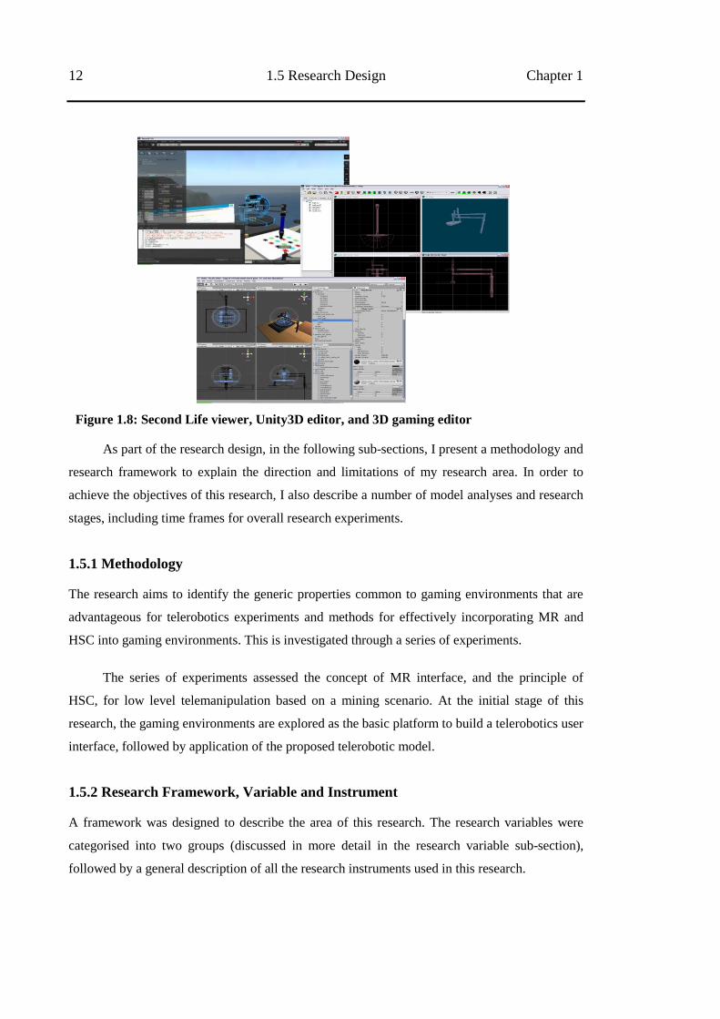
Figure 1.8: Second Life viewer, Unity3D editor, and 3D gaming editor ................ 12
Figure 1.9: Research framework ............................................................................. 15
Figure 1.10: Stage of research ................................................................................... 16
Figure 1.11: Timeline ................................................................................................ 19
Figure 2.1: A Second Life client interface showing an avatar that is creating
virtual objects; and the Second Life logo [46] ...................................... 24
Figure 2.2: Communication flow diagram between telerobotics interface and
telerobot through third party server ...................................................... 25
Figure 2.3: Mycosm studio editor and logo [47] ..................................................... 27
Figure 2.4: Unity3D editor and logo [48] ................................................................ 28
Figure 2.5: Direct communication flow diagram .................................................... 28
Figure 2.6: Control based on the virtual reality (VR) model .................................. 33
Figure 2.7: Control based on the classic model ....................................................... 33
Figure 2.8: Coordinated telerobotic control system based on the virtual reality
(VR) model ........................................................................................... 34
Figure 2.9: Classic looping control system ............................................................. 34
xxiv
Figure 2.10: Proposed control system design based on control by virtual reality
(VR) simulation .................................................................................... 34
Figure 2.11: Telerobot system architecture [3] ......................................................... 35
Figure 2.12: Software telerobotic architecture based on client server and
operation by virtual simulation ............................................................. 37
Figure 2.13: System configuration ............................................................................ 38
Figure 2.14: Telerobotics user interface with multiple screens to monitor each
sub- telerobotics process [5] ................................................................. 39
Figure 2.15: Perspective: determined by centre of projection .................................. 42
Figure 2.16: Examples of video interfaces in a monitor as part of a UAV play
load and control mechanism[71] .......................................................... 42
Figure 2.17: This example of a VR interface shows the RSVP-HyperDrive, which
displays a graphical version of the rover that is used to drive the
MER Spirit rover and place its robotic arm on rocks [21] ................... 43
Figure 2.18: Sample of mixed reality (MR) concept ................................................ 45
Figure 2.19: Simplified representation of MR (referred to [64]) .............................. 46
Figure 2.20: Examples of AR interfaces. (Left) Embedded country flags and the
names of sailors are displayed on the screen for the America‘s Cup
race tracking display [84], and (Right) An arrow object as additional
navigation interface [85] ....................................................................... 47
Figure 2.21: Example of an AV interface concept from TV newscasters who sit at
a real table in a virtual studio [88] ........................................................ 47
Figure 2.22: MR environment in gaming environment ............................................. 50
Figure 2.23: Five generic supervisor functions as nested control loop ..................... 51
Figure 2.24: Spectrum control diagram (referred to by Sheridan [2]) ...................... 52
Figure 2.25: The LiSA (Localization and Semantics of Assistance) model concept
with perception reconstruction, virtual execution, action generation,
and action reconstruction model assistance (from [23]) ...................... 53
Figure 2.26: An example of path finding implementation for the gaming
environment [95] .................................................................................. 55
Figure 2.27: Diagram of Adaptation and Queue response model ............................. 57
Figure 2.28: The system‘s architecture of Rockbreaker [5 ] ..................................... 59
Figure 2.29: First trial overview of telerobotics using the Second Life (SL)
environment .......................................................................................... 61
xxv
Figure 2.30: DDX framework ................................................................................... 62
Figure 2.31: ABB robot telerobotic client interface [67] .......................................... 64
Figure 2.32: File lock concept applied ...................................................................... 65
Figure 3.1: Robot arm, workspace and two remote cameras .................................. 69
Figure 3.2: MR concept built in Second Life (SL) .................................................. 70
Figure 3.3: MR concept built in Simmersion (Sm) ................................................. 71
Figure 3.4: An overview of the experiment‘s architecture: (1 and 3) streaming
video from the camera, (2 and 4) 3D model white board ..................... 72
Figure 3.5: Attention level of participants to the 3D model for the first and
second tasks using SL environment ...................................................... 78
Figure 3.6: Attention level of participants to 3D model for the first and second
task using Sm environment ................................................................... 81
Figure 3.7: Preferred environment based on questionnaire ..................................... 84
Figure 4.1: Remote settings and 3D model of remote settings based on Unity3D
game engine: (1) Robot arm with engraver attached, (2) Rocks –
targets objects, (3) Worksite - board with a hole in the middle ............ 91
Figure 4.2: The ―ghost‖ tip in transparent green ..................................................... 91
Figure 4.3: Remote IP camera ................................................................................. 92
Figure 4.4: Rock tracking steps in OpenCV ............................................................ 93
Figure 4.5: Calibration and registering process ....................................................... 93
Figure 4.6: Application and image processing ........................................................ 94
Figure 4.7: The virtual camera in virtual environment can show scenes from any
angle ...................................................................................................... 95
Figure 4.8: The helping line model (vertical line) to show the height tip position . 96
Figure 4.9: Remote setting test rig: (1) Robot arm from Phantom Premium V.1.5
haptic device, (2) Board with a hole in the middle, (3) Rocks –
targets objects, (4) Camera. .................................................................. 97
Figure 4.10: User setting: (1) Unit PC with situated virtual application running on
it, (2) FaceLAB V.4.5 eye tracker software and sensors, (3) Logitech
Dual Action gamepad ............................................................................ 98
Figure 4.11: Mapping gamepad control: (1) Left – Viewpoint movement, (2)
Right - TIP movement .......................................................................... 98
Figure 4.12: Robot or camera centric ........................................................................ 99
Figure 4.13: Telerobotics system with virtual application interface ......................... 99
xxvi
Figure 4.14: Mean number of rocks sunk (a) and number of nudges (b) for each
operation period. ................................................................................. 104
Figure 4.15: Subjective measurement variables ...................................................... 105
Figure 4.16: Total number of rocks sunk on a full video interface* and a gaming
environment interface using two different input devices (*data from
[39]) .................................................................................................... 106
Figure 4.17: Total number of nudges on a full video interface* and a gaming
environment interface using two different input devices (*data from
[39]) .................................................................................................... 107
Figure 5.1: MR concept built in Unity3D ............................................................. 113
Figure 5.2: Telerobotics system ............................................................................ 114
Figure 5.3: Path generated from the A-star algorithm in: (a) selected block, and
(b) unselected block model ................................................................. 116
Figure 5.4: Visual information: (1) green circles, (2) shadow of tip, (3) line path,
and (4) overlay pointer ........................................................................ 117
Figure 5.5: Experimental setup for third experiment ............................................ 118
Figure 5.6: Logistic Regression showing the relationship between the probability
of success and completion time .......................................................... 122
Figure 5.7: Scatter plot – performance and completion time for four supervisory
models tested ...................................................................................... 123
Figure 5.8: The relationship between task results ................................................. 124
Figure 6.1: Probability Density Function (pdf) and Cumulative Distribution
Function (cdf) with selected values of the shape parameter ............... 135
Figure 6.2: Probability Density Function (pdf) and Cumulative Distribution
Function (cdf) with variant of scale parameter ................................... 136
Figure 6.3: The effect of location parameter in Probability Density Function
(pdf) and Cumulative Distribution Function (cdf) .............................. 136
Figure 6.4: Preview of information screens for the telerobotic interfaces ............ 138
Figure 6.5: Menu buttons representing each model control tested........................ 139
Figure 6.6: Overview of the exhibition ................................................................. 141
Figure 6.7: The comparison between the Weibull curve and observed data in
HSC with the Adaptation response model, from a sample of 2218
sessions, which is showing the range between 1 – 80 requests to the
telerobotic interface ............................................................................ 146
xxvii
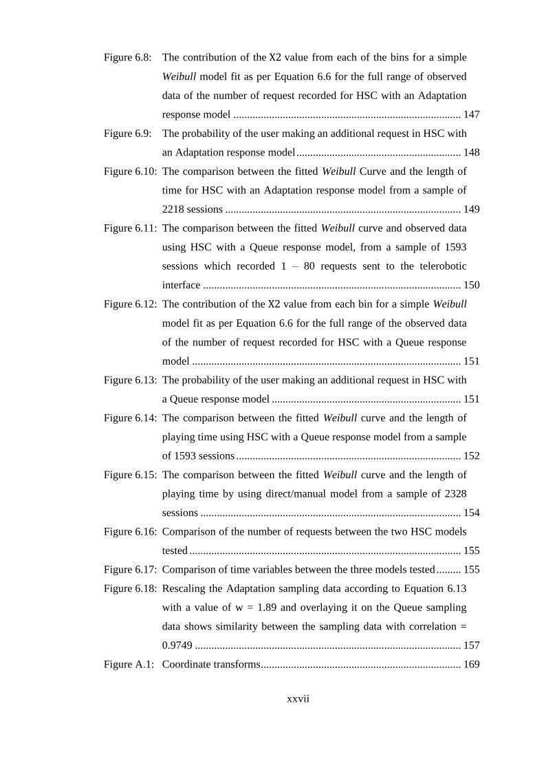
Figure 6.8: The contribution of the value from each of the bins for a simple
Weibull model fit as per Equation 6.6 for the full range of observed
data of the number of request recorded for HSC with an Adaptation
response model ................................................................................... 147
Figure 6.9: The probability of the user making an additional request in HSC with
an Adaptation response model ............................................................ 148
Figure 6.10: The comparison between the fitted Weibull Curve and the length of
time for HSC with an Adaptation response model from a sample of
2218 sessions ...................................................................................... 149
Figure 6.11: The comparison between the fitted Weibull curve and observed data
using HSC with a Queue response model, from a sample of 1593
sessions which recorded 1 – 80 requests sent to the telerobotic
interface .............................................................................................. 150
Figure 6.12: The contribution of the value from each bin for a simple Weibull
model fit as per Equation 6.6 for the full range of the observed data
of the number of request recorded for HSC with a Queue response
model .................................................................................................. 151
Figure 6.13: The probability of the user making an additional request in HSC with
a Queue response model ..................................................................... 151
Figure 6.14: The comparison between the fitted Weibull curve and the length of
playing time using HSC with a Queue response model from a sample
of 1593 sessions .................................................................................. 152
Figure 6.15: The comparison between the fitted Weibull curve and the length of
playing time by using direct/manual model from a sample of 2328
sessions ............................................................................................... 154
Figure 6.16: Comparison of the number of requests between the two HSC models
tested ................................................................................................... 155
Figure 6.17: Comparison of time variables between the three models tested ......... 155
Figure 6.18: Rescaling the Adaptation sampling data according to Equation 6.13
with a value of w = 1.89 and overlaying it on the Queue sampling
data shows similarity between the sampling data with correlation =
0.9749 ................................................................................................. 157
Figure A.1: Coordinate transforms ......................................................................... 169
xxviii
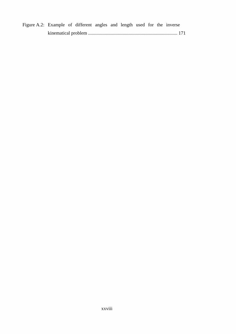
Figure A.2: Example of different angles and length used for the inverse
kinematical problem ........................................................................... 171
xxix
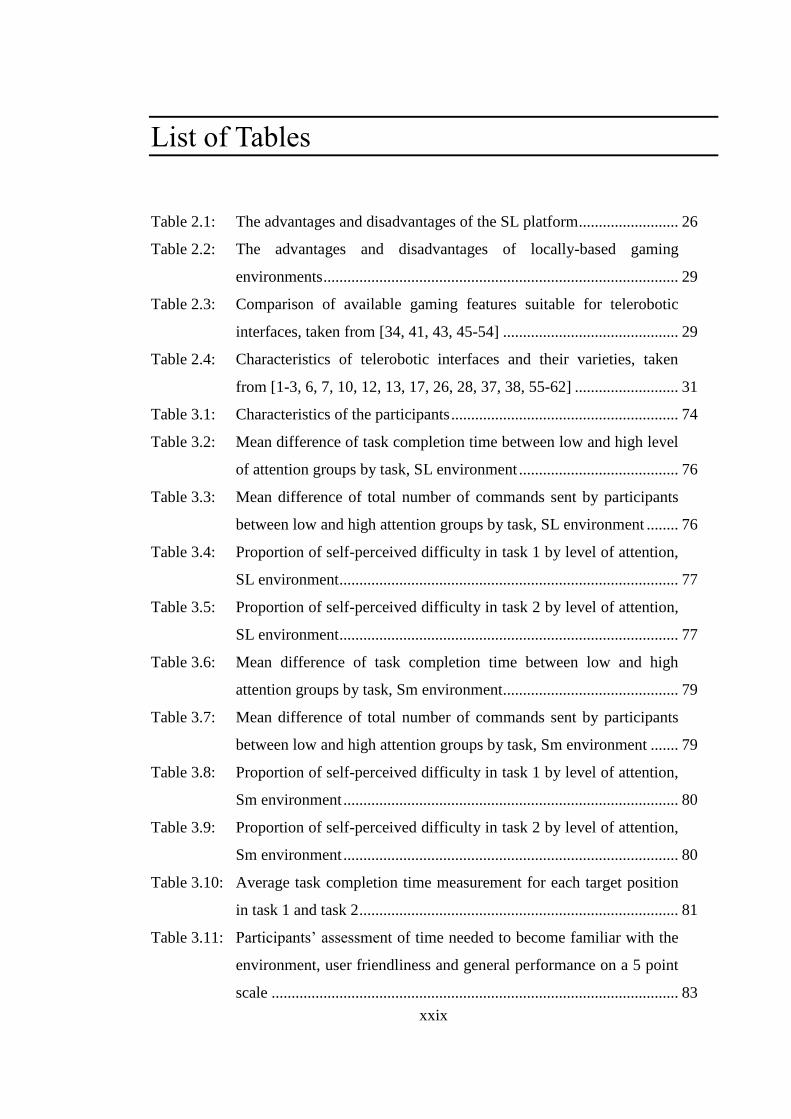
List of Tables
Table 2.1: The advantages and disadvantages of the SL platform ......................... 26
Table 2.2: The advantages and disadvantages of locally-based gaming
environments ......................................................................................... 29
Table 2.3: Comparison of available gaming features suitable for telerobotic
interfaces, taken from [34, 41, 43, 45-54] ............................................ 29
Table 2.4: Characteristics of telerobotic interfaces and their varieties, taken
from [1-3, 6, 7, 10, 12, 13, 17, 26, 28, 37, 38, 55-62] .......................... 31
Table 3.1: Characteristics of the participants ......................................................... 74
Table 3.2: Mean difference of task completion time between low and high level
of attention groups by task, SL environment ........................................ 76
Table 3.3: Mean difference of total number of commands sent by participants
between low and high attention groups by task, SL environment ........ 76
Table 3.4: Proportion of self-perceived difficulty in task 1 by level of attention,
SL environment ..................................................................................... 77
Table 3.5: Proportion of self-perceived difficulty in task 2 by level of attention,
SL environment ..................................................................................... 77
Table 3.6: Mean difference of task completion time between low and high
attention groups by task, Sm environment ............................................ 79
Table 3.7: Mean difference of total number of commands sent by participants
between low and high attention groups by task, Sm environment ....... 79
Table 3.8: Proportion of self-perceived difficulty in task 1 by level of attention,
Sm environment .................................................................................... 80
Table 3.9: Proportion of self-perceived difficulty in task 2 by level of attention,
Sm environment .................................................................................... 80
Table 3.10: Average task completion time measurement for each target position
in task 1 and task 2 ................................................................................ 81
Table 3.11: Participants‘ assessment of time needed to become familiar with the
environment, user friendliness and general performance on a 5 point
scale ...................................................................................................... 83
xxx
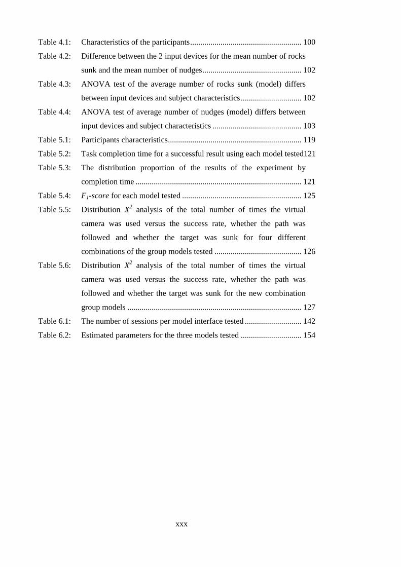
Table 4.1: Characteristics of the participants ....................................................... 100
Table 4.2: Difference between the 2 input devices for the mean number of rocks
sunk and the mean number of nudges ................................................. 102
Table 4.3: ANOVA test of the average number of rocks sunk (model) differs
between input devices and subject characteristics .............................. 102
Table 4.4: ANOVA test of average number of nudges (model) differs between
input devices and subject characteristics ............................................ 103
Table 5.1: Participants characteristics .................................................................. 119
Table 5.2: Task completion time for a successful result using each model tested121
Table 5.3: The distribution proportion of the results of the experiment by
completion time .................................................................................. 121
Table 5.4: F1-score for each model tested ........................................................... 125
Table 5.5: Distribution X2 analysis of the total number of times the virtual
camera was used versus the success rate, whether the path was
followed and whether the target was sunk for four different
combinations of the group models tested ........................................... 126
Table 5.6: Distribution X2 analysis of the total number of times the virtual
camera was used versus the success rate, whether the path was
followed and whether the target was sunk for the new combination
group models ...................................................................................... 127
Table 6.1: The number of sessions per model interface tested ............................ 142
Table 6.2: Estimated parameters for the three models tested .............................. 154
1
Chapter 1
Introduction
1.1 Telerobotics
1.1.1 What is Telerobotics?
The term telerobotics consists of two words ―tele‖ and ―robotics‖, and refers to a branch of
technology that utilises a computer system for control, sensor feedback and the processing of
information from a robot at a distance. There are several definitions of telerobotics used by
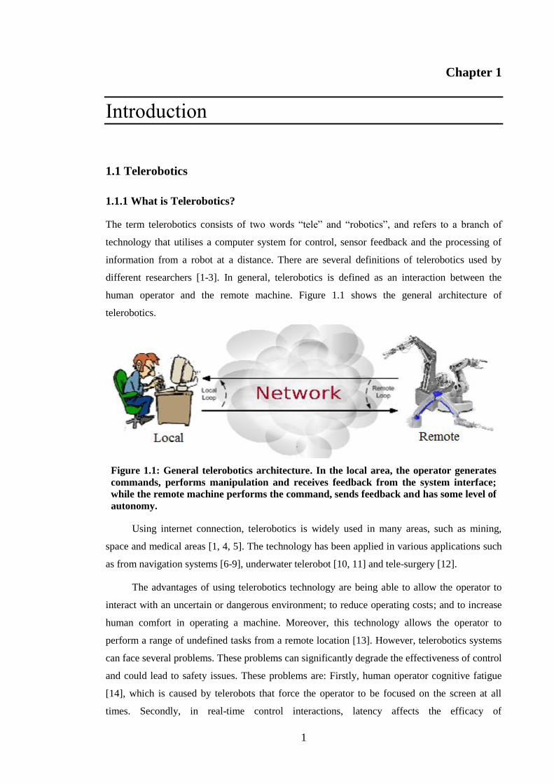
different researchers [1-3]. In general, telerobotics is defined as an interaction between the
human operator and the remote machine. Figure 1.1 shows the general architecture of
telerobotics.
Figure 1.1: General telerobotics architecture. In the local area, the operator generates
commands, performs manipulation and receives feedback from the system interface;
while the remote machine performs the command, sends feedback and has some level of
autonomy.
Using internet connection, telerobotics is widely used in many areas, such as mining,
space and medical areas [1, 4, 5]. The technology has been applied in various applications such
as from navigation systems [6-9], underwater telerobot [10, 11] and tele-surgery [12].
The advantages of using telerobotics technology are being able to allow the operator to
interact with an uncertain or dangerous environment; to reduce operating costs; and to increase
human comfort in operating a machine. Moreover, this technology allows the operator to
perform a range of undefined tasks from a remote location [13]. However, telerobotics systems
can face several problems. These problems can significantly degrade the effectiveness of control
and could lead to safety issues. These problems are: Firstly, human operator cognitive fatigue
[14], which is caused by telerobots that force the operator to be focused on the screen at all
times. Secondly, in real-time control interactions, latency affects the efficacy of
2 1.1 Telerobotics Chapter 1
telemanipulation under manual control [15, 16]. In direct/manual control, the operator
continually controls the robot movement. Delay in the response from the telerobot can cause the
operator to overcorrect for errors that are different from the actual robot errors. This causes the
robot to move in ways unexpected by the operator and the operator to provide further
corrections, which again do not reflect the errors at the robot. Errors tend to grow and this is
often referred to as instability. With some forms of feedback e.g. force feedback it is impossible
for the operator to avoid instability when the delay is too great. With other forms of feedback,
and where the situation at the robot is not varying much, an operator can sometimes avoid
instability by making a series of movements, then stopping and waiting longer than the delay
period to observe the result before repeating the process. Thirdly, incomplete information from
the remote location. According to a number of researchers [3, 6, 10, 13], providing complete
information about the remote location into a single interface is a major challenge in telerobotic
scenarios. For example, a limited range of vision from a remote video camera cannot replace
operator eyes that are able to explore the remote environment directly and which can be moved
to a different view point if required. This missing information can lead to degradation in
operator performance. The fourth issue is having unfriendly user interfaces. Interfaces
sometimes can be difficult to use which can be caused by using too many graphical components
(e.g., buttons, sliders or graphics) to control the telerobot or non-intuitive graphical
representations and controls [28, 33]. This can make the operation unnecessarily complicated.
Currently, the Line-of-sight remote control is a form of telerobotics technology, which is
widely used in mining and other industries [6]. This technology has been proven to be effective
in protecting the operator from hazards, for example the underground Load-Haul-Dump (LHD)
vehicle operating in a location where the roof is unsupported and there is occasioned rock falls.
Nonetheless, the operator still needs direct vision to control the machine, which may
compromise the safety of the operator. According to Fong and Thrope [1], there are three
characteristics which distinguish the term telerobotics from the remote control (Line-of-sight
remote control). As the impact of the different location between operator and remote machine,
compare to remote control, telerobotics requires: Firstly, a more reliable navigation system;
Secondly, more efficient motion commands; and Thirdly, better remote sensors to provide the
information that is needed by the operator.
1.1.2 Type of Telerobotics
According to Fong et al. [17], telerobotics can be categorised into vehicle telerobotics and
telemanipulation. The general difference between these two categories relates to the function of
the remote machine. Vehicle telerobotics can explore areas that are difficult for humans to
Chapter 1 Introduction 3
reach; for telemanipulation, however, the remote machine typically performs its tasks in one
static position. Many telerobotics systems are built using a combination of these two categories,
depending on their purpose and task.
A vehicle telerobotic is widely used to explore an area or space when it is hard or
dangerous for a human to reach yet still requires human intelligence [18]. Research conducted
by Monferer and Bonyuet [11] is one of many examples of vehicle telerobotics. Their research
investigated cooperative control for underwater telerobotics also known as ‘GARBI’
(underwater robot). Utilising a virtual reality (VR) interface, Monferer and Bonyuet tested the
possibility of sharing information and collaborating in the underwater environment with two
users. Lin and Kuo [10] conducted a similar experiment which investigated pilot training for
underwater telerobotics using a VR environment.
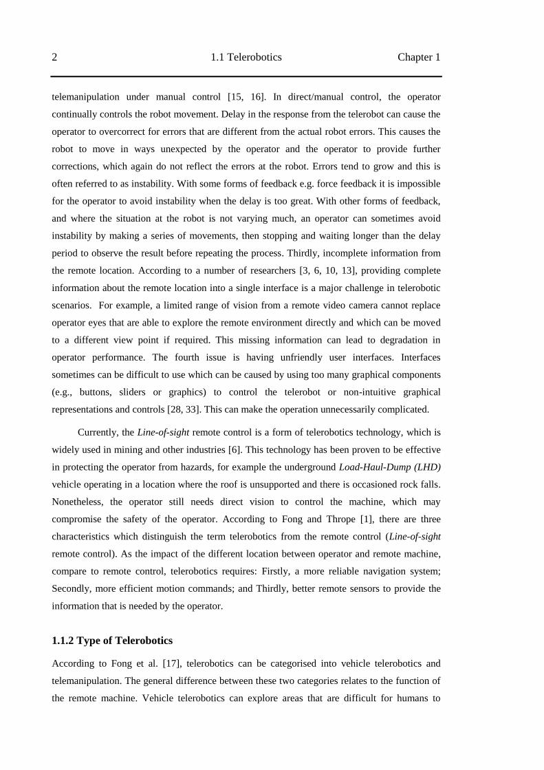
For telemanipulation applications, research as reported by Duff et al [5] shows the
telemanipulation of a large Rockbreaker robot (Figure 1.2) in iron ore mining. They built a
telerobotics system for a large Rockbreaker that was located over 1,000 km from the operator.
Figure 1.2: Rockbreaker robot arm from [5]
4 1.1 Telerobotics Chapter 1
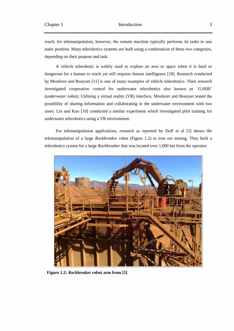
Figure 1.3: TUI (Telerobotics User Interfaces) for telerobotics Rockbreaker from [5]
In their research, Duff‘et al‘s telerobotics user interface (Figure 1.3) consisted of three
live videos and a 3D model of the robot arm Rockbreaker in a single display. The three live
videos showed different viewpoints from remote cameras. Two cameras showed information on
the bin and the arm‘s position from different angles. The third camera provided information on
the view from the front of the bin, where the truck loads the rocks into the bin.
As indicated by Duff et al‘s research [5], when the operator is collocated with the
machine, the operator can concentrate on the task and simultaneously manage other duties. On
the contrary, when the operator was in a remote location, their attention was divided across
monitoring numerous custom built interfaces, hence potentially reducing operator performance.
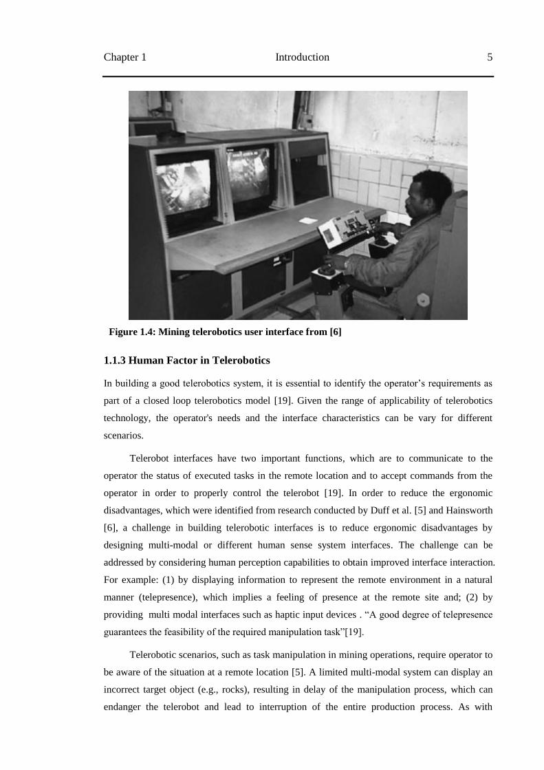
Hainsworth [6] identified a related problem. He argued that implementing direct/manual
operator control using multiple screens for telerobotic interfaces has ergonomic disadvantages
(see Figure 1.4), whereby the operator is forced to continuously focus on the screen in order to
identify the position of the desired control and the degree of control input being applied. When
compounded by a high workload, this becomes exhausting and eventually leads to operator
error.
Chapter 1 Introduction 5
Figure 1.4: Mining telerobotics user interface from [6]
1.1.3 Human Factor in Telerobotics
In building a good telerobotics system, it is essential to identify the operator‘s requirements as
part of a closed loop telerobotics model [19]. Given the range of applicability of telerobotics
technology, the operator's needs and the interface characteristics can be vary for different
scenarios.
Telerobot interfaces have two important functions, which are to communicate to the
operator the status of executed tasks in the remote location and to accept commands from the
operator in order to properly control the telerobot [19]. In order to reduce the ergonomic
disadvantages, which were identified from research conducted by Duff et al. [5] and Hainsworth
[6], a challenge in building telerobotic interfaces is to reduce ergonomic disadvantages by
designing multi-modal or different human sense system interfaces. The challenge can be
addressed by considering human perception capabilities to obtain improved interface interaction.
For example: (1) by displaying information to represent the remote environment in a natural
manner (telepresence), which implies a feeling of presence at the remote site and; (2) by
providing multi modal interfaces such as haptic input devices . ―A good degree of telepresence
guarantees the feasibility of the required manipulation task‖[19].
Telerobotic scenarios, such as task manipulation in mining operations, require operator to
be aware of the situation at a remote location [5]. A limited multi-modal system can display an
incorrect target object (e.g., rocks), resulting in delay of the manipulation process, which can
endanger the telerobot and lead to interruption of the entire production process. As with
6 1.1 Telerobotics Chapter 1
telerobotics used in space [21] or forestry operations [22], inaccurate or missing information
about the remote environment can put the operation at risk; it can trigger a situation that
damages the environment, including the telerobot. Besides sufficient information of the remote
environment, the operator needs feedback on the congruence between the commands given and
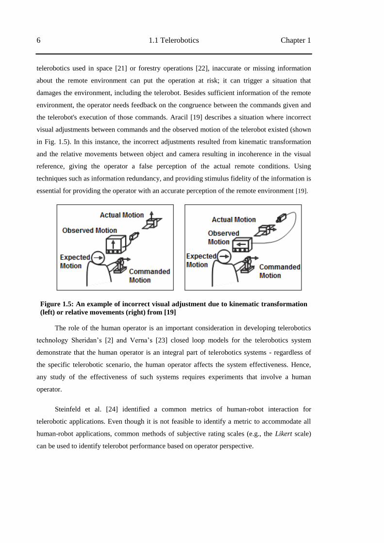
the telerobot's execution of those commands. Aracil [19] describes a situation where incorrect
visual adjustments between commands and the observed motion of the telerobot existed (shown
in Fig. 1.5). In this instance, the incorrect adjustments resulted from kinematic transformation
and the relative movements between object and camera resulting in incoherence in the visual
reference, giving the operator a false perception of the actual remote conditions. Using
techniques such as information redundancy, and providing stimulus fidelity of the information is
essential for providing the operator with an accurate perception of the remote environment [19].
Figure 1.5: An example of incorrect visual adjustment due to kinematic transformation
(left) or relative movements (right) from [19]
The role of the human operator is an important consideration in developing telerobotics
technology Sheridan‘s [2] and Verna‘s [23] closed loop models for the telerobotics system
demonstrate that the human operator is an integral part of telerobotics systems - regardless of
the specific telerobotic scenario, the human operator affects the system effectiveness. Hence,
any study of the effectiveness of such systems requires experiments that involve a human
operator.
Steinfeld et al. [24] identified a common metrics of human-robot interaction for
telerobotic applications. Even though it is not feasible to identify a metric to accommodate all
human-robot applications, common methods of subjective rating scales (e.g., the Likert scale)
can be used to identify telerobot performance based on operator perspective.
Chapter 1 Introduction 7
1.1.4 Technology of Telerobotics
Direct/manual control is the most common type of control method for telerobotics [1, 6 , 39, 60].
In this control model, the operator controls a remote machine directly using a hand-controller,
specifies the speed and direction of movement, and monitors and adjusts the controls
continually. A number of studies have attempted to improve this direct/manual model control
through adding multiple modalities, including haptic [25, 26] and other input devices [27]. In a
situation where communications are substantially delayed, relative to the speed of movement,
the resulting instability requires that the system be able to run independently—requiring little
input from the human operator. HSC [2] addresses this issue, increasing productivity and
making it easier for the operator to perform tasks. HSC allows the operator to specify tasks for
an intelligent system without continuous operator involvement. This also reduces operator
workload.
In terms of further development of telerobotics, previous research has been undertaken
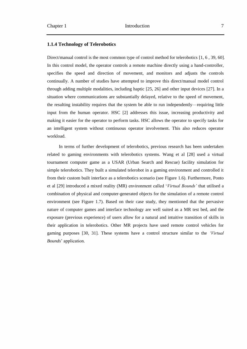
related to gaming environments with telerobotics systems. Wang et al [28] used a virtual
tournament computer game as a USAR (Urban Search and Rescue) facility simulation for
simple telerobotics. They built a simulated telerobot in a gaming environment and controlled it
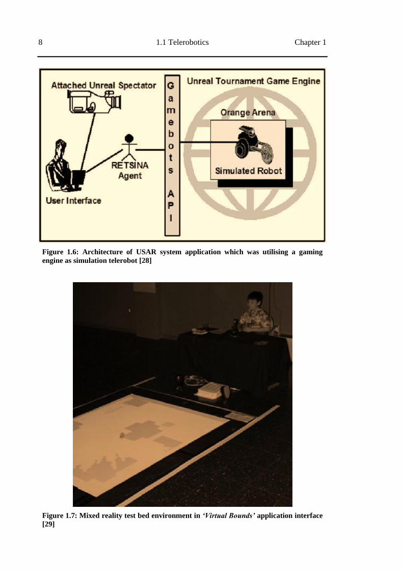
from their custom built interface as a telerobotics scenario (see Figure 1.6). Furthermore, Ponto
et al [29] introduced a mixed reality (MR) environment called ‗Virtual Bounds’ that utilised a
combination of physical and computer-generated objects for the simulation of a remote control
environment (see Figure 1.7). Based on their case study, they mentioned that the pervasive
nature of computer games and interface technology are well suited as a MR test bed, and the
exposure (previous experience) of users allow for a natural and intuitive transition of skills in
their application in telerobotics. Other MR projects have used remote control vehicles for
gaming purposes [30, 31]. These systems have a control structure similar to the ‘Virtual
Bounds‘ application.
8 1.1 Telerobotics Chapter 1
Figure 1.6: Architecture of USAR system application which was utilising a gaming
engine as simulation telerobot [28]
Figure 1.7: Mixed reality test bed environment in ‘Virtual Bounds’ application interface
[29]
Chapter 1 Introduction 9
A review of existing literature indicates that advances in the gaming environment may
allow it to be utilised as a telerobotic interface. Moreover, virtual gaming provides a
sophisticated setting to build and define a 3D model. It can also be used to communicate
information within the virtual world or between virtual and real world applications (e.g. client-
server communication). Virtual gaming is usually designed to be easy to operate (user friendly).
By utilising the multiplayer functions, a virtual gaming environment, which is played online
through the internet, can possibly be utilised for collaborative control of telerobotics systems.
However, there are some differences between a telerobotic interface and a virtual gaming
environment. Firstly, virtual gaming has task scenarios without any consequences if the user
fails to accomplish the task. While in telerobotics, a failure in task accomplishment would not
be acceptable as it has real-life consequences. Secondly, in providing incomplete simulated
information, gaming visualisations are already video simulations, and telerobotic interfaces can
be equipped with video.
Regardless of the advances in virtual gaming environments, it is difficult to provide real-
time complete information of remote situations. This occurs because of inadequate sensing that
leads to inaccurate and incomplete models of the remote environment sensor cannot provide the
information due to frequently changing conditions in many mining. A simulation is easier
because the robot situation is precisely understood by the operator interface. In a real system
there is only limited knowledge of the external system state.
To overcome these shortcomings, I propose building telerobotic interfaces using gaming
environments with a concept of mixed-reality (MR) environment and the principle of human-
supervisory-control (HSC). Both MR and HSC have been utilised in many applications [32].
However, applying these two concepts into a gaming environment for the telerobotics scenario
is not common, since gaming and telerobotic interface are seen as different domains. This thesis
explores the features of the gaming environments, which are useful in applying MR and HSC, to
improve the system and overcome the existing limitations from the current telerobotics scenario.
Further exploration on MR and HSC concepts in gaming environments are discussed through
the conducted experiments in the following chapters.
1.2 Research Topic
The thesis evaluates gaming environments for mixed reality (MR) interface and human
supervisory control (HSC) in telerobotics.
The research project goals are to improve telerobotics interfaces for manipulation
scenarios, and apply an alternative remote interface with current immersive technologies,
normally used for gaming.
10 1.3 Research Outcomes Chapter 1
The research project aims to develop an application prototype for telerobotics in remote
mining equipment scenarios by utilising the features of gaming environments. This project
investigates MR interfaces and the use of HSC concepts for the control model, and conducts
usability testing to determine the effectiveness of the scenario based on operator satisfaction.
This research is associated with the ―Future Mining‖ theme under the CSIRO Minerals
Down Under (MDU) Flagship, with supervision by Dr. Ken Taylor (ICT Centre, CSIRO), Prof.
Tom Gedeon (Research School of Computer Science, ANU) and Assoc. Prof. Henry Gardner
(Head School of Computer Science, ANU).
1.3 Research Outcomes
The major outcome of this research is to improve user interfaces for telerobotics designs,
particularly in telemanipulation for mining scenarios. The key components of the potential
outcomes are listed below:
1. Enhanced knowledge of the features of gaming environments for telerobotics user
interfaces, including assessing its feasibility and evaluating its performance.
2. Prototype telerobotic system interface:
Applying telerobotics user interfaces that integrate real world sensor information
from remote locations (e.g. cameras) into a model in a virtual environment (which
can be called a MR environment) providing sophisticated information on a single
screen for the operator.
Applying the principle of HSC in the design of telerobotic user interfaces improves
the autonomy of the remote machine and allows it to adapt to dynamic
environments. This method also enables the operator to monitor and interrupt the
process when needed.
1.4 Contributions
Contributions from this research are:
1. Exploring a number of virtual gaming environments that may be used as telerobotic
interfaces, especially for telemanipulation in mining. This includes:
Identification of virtual reality interface (gaming environments) components
and functionalities that are necessary and useful for telerobotics and those that
are not.
Chapter 1 Introduction 11
Evaluation of user satisfactions and preferences regarding the ideal source of
information and the required feature set from the gaming engine for telerobotic
interfaces.
2. Evaluating user performance in using gaming environment with the principle of human
supervisory control (HSC) and mixed reality (MR) for telerobotic interfaces.
3. Applying HSC and MR concepts to telerobotic interfaces in a gaming environment
addresses a number of issues raised by Duff et al [5] and Hainsworth [6], including:
Regardless of the different types of input devices, determining whether the use
of multiple information displays increases operator cognitive fatigue, which
affects their attention to the interface and reduces performance.
Improving effectiveness and user friendliness of the telerobotic interface.
Reducing safety concerns and implicitly decreasing the effect of latency.
The next section presents the research design as guidance for my research direction and
limitation.
1.5 Research Design
In this research, investigating gaming environments for MR interface and HSC concepts for
telerobotic interfaces is proposed.
Gaming environments have been utilised by a number of previous studies such as: (1)
Richer and Drury [33] which successful classify a video gaming based framework for human
machine interaction. They grouped video gaming users‘ interaction using this framework which
could potentially be used for human machine interaction design. (2) Bourke [34] who
mentioned a gaming technology is advanced as it provides a sophisticated environment for
creating 3D models or programming, and (3) Chung[25] and Schou [35, 36] that demonstrated
virtual gaming environments to provide an immersive environment. Based on these previous
studies, I proposed to utilise a gaming environment for telerobotic interfaces.
A number of virtual gaming environments, such as Unity3D and Second Life (see Figure
1.8) can be used as a basic environment for building telerobotic interfaces. For future
development, the multiplayer function provided by virtual gaming environments can be utilised
for collaborative telerobotics control. Collaborative control can be defined as the collaboration
of humans and semi-autonomous systems to perform a task and achieve a goal. This is
described in research conducted by Fong on multi-robot remote driving [37, 38] and that
conducted by Monferrer [11] on cooperation among operators in controlling telerobots.
12 1.5 Research Design Chapter 1
Figure 1.8: Second Life viewer, Unity3D editor, and 3D gaming editor
As part of the research design, in the following sub-sections, I present a methodology and
research framework to explain the direction and limitations of my research area. In order to
achieve the objectives of this research, I also describe a number of model analyses and research
stages, including time frames for overall research experiments.
1.5.1 Methodology
The research aims to identify the generic properties common to gaming environments that are
advantageous for telerobotics experiments and methods for effectively incorporating MR and
HSC into gaming environments. This is investigated through a series of experiments.
The series of experiments assessed the concept of MR interface, and the principle of
HSC, for low level telemanipulation based on a mining scenario. At the initial stage of this
research, the gaming environments are explored as the basic platform to build a telerobotics user
interface, followed by application of the proposed telerobotic model.
1.5.2 Research Framework, Variable and Instrument
A framework was designed to describe the area of this research. The research variables were
categorised into two groups (discussed in more detail in the research variable sub-section),
followed by a general description of all the research instruments used in this research.
Chapter 1 Introduction 13
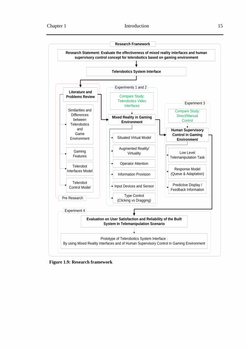
1.5.2.1 Research Framework
The research commenced with the exploration of the gaming environment. Then, it was
followed by the utilisation and investigation of the MR concept and the principle of HSC to
improve human machine interfaces in a telerobotics mining scenario.
The main environment in this research is a gaming environment modified for telerobotic
interfaces. The user was provided with information on the remote location through this
environment. Communication between the user and the remote machine was tested and
recorded. Performance variables and the times needed for accomplishing the experimental tasks
were recorded, with user preferences and feedback captured in a questionnaire.
I began the research with a review of existing literature and those applications that
utilised MR or HSC in the telerobotics area. A number of gaming environments were
investigated to assess the feasibility of using their technologies to communicate with a number
of remote machines/servers. Then, four experiments were conducted to evaluate the user
performance on the proposed telerobotic interfaces. These four experiments are further
discussed in the following paragraphs.
The first experiment primarily covered an exploration of the number of gaming
environments. Features of gaming environments were also evaluated to encompass more detail
about the effectiveness of using MR concepts for telerobotic interfaces. Since all of the
information was presented on a single display, it suggested that the operators might have more
or less focused into a telerobotic interface. Hence, there is an attempt to evaluate operator
performance based on their level of attention in using mixed information in a single display
interface.
Based on the first experimental result, it was possible to improve the MR environment by
applying additional sensing to detect the block position and provide an additional 3D model of
the block. Hence, the second experiment covered an evaluation of user performance in gaming
environments with this additional sensing. Here, the gaming environment was also tested with
additional input devices, gamepad and eye-tracking, for virtual camera control.
The third experiment encompassed an evaluation of gaming environments for human
supervisory control (HSC). In this experiment, a number of features from the gaming
environment were utilised. These features included the concept of the first person viewpoint for
camera control, a path finding algorithm, and additional virtual information such as planning
and feedback. These features were tested using two response models, the Queue and the
Adaptation response models, as a method of dealing with multiple commands in HSC. A
gaming feature, such as predictive display for the planning process, was also used in this
14 1.5 Research Design Chapter 1
experiment. Hence, a sub experiment of direct/manual control was also performed to compare
operator performance.
In the fourth experiment, I tested the gaming environment using random participants from
a variety of backgrounds. This gaming environment was located in an exhibition for period of
three months. This gaming environment successfully recorded the variables ‗commands‘ and
‗usage time‘ of the participants. This experiment described general operator behaviour and
satisfaction of the developed telerobotic system interfaces. I presented a distribution analysis to
describe the trend of user performance in this experiment. The design of the research framework
can be seen in Figure 1.9, and a description of each stage of the research can be seen in Figure
1.10.
Chapter 1 Introduction 15
Telerobotics System Interface
Literature and
Problems Review
Mixed Reality in Gaming
Environment
Human Supervisory
Control in Gaming
Environment
Gaming
Features
Telerobot
Interfaces Model
Situated Virtual Model
Augmented Reality/
Virtuality
Operator Attention
Type Control
(Clicking vs Dragging)
Compare Study:
Direct/Manual
Control
Response Model
(Queue & Adaptation)
Predictive Display /
Feedback Information
Similarities and
Differences
between
Telerobotics
and
Game
Environment
Research Statement: Evaluate the effectiveness of mixed reality interfaces and human
supervisory control concept for telerobotics based on gaming environment
Information Provision
Telerobot
Control Model
Prototype of Telerobotics System Interface :
By using Mixed Reality Interfaces and of Human Supervisory Control in Gaming Environment
Evaluation on User Satisfaction and Reliability of the Built
System In Telemanipulation Scenario
Pre Research
Experiments 1 and 2
Experiment 3
Experiment 4
Research Framework
Compare Study:
Telerobotics Video
Interfaces
Input Devices and Sensor
Low Level
Telemanipulation Task
Figure 1.9: Research framework
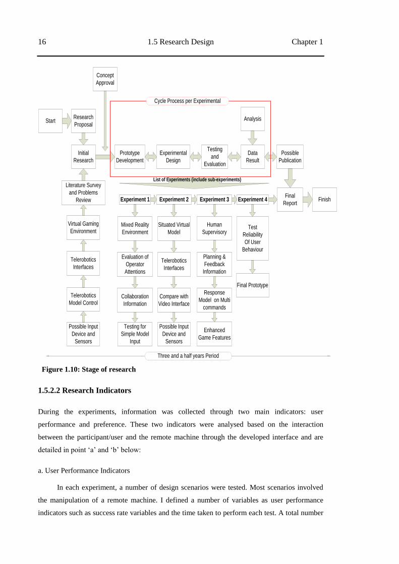
16 1.5 Research Design Chapter 1
Research
Proposal
Initial
Research
Literature Survey
and Problems
Review
Concept
Approval
Prototype
Development
Experimental
Design
Testing
and
Evaluation
Analysis
Data
Result
Possible
Publication
Experiment 1 Experiment 2 Experiment 3
Situated Virtual
Model
Compare with
Video Interface
Possible Input
Device and
Sensors
Mixed Reality
Environment
Evaluation of
Operator
Attentions
Collaboration
Information
Testing for
Simple Model
Input
Human
Supervisory
Planning &
Feedback
Information
Enhanced
Game Features
Response
Model on Multi
commands
Experiment 4
Test
Reliability
Of User
Behaviour
Telerobotics
Interfaces
Start
Final Prototype
Final
ReportFinish
Cycle Process per Experimental
List of Experiments (include sub-experiments)
Three and a half years Period
Virtual Gaming
Environment
Telerobotics
Model Control
Possible Input
Device and
Sensors
Telerobotics
Interfaces
Figure 1.10: Stage of research
1.5.2.2 Research Indicators
During the experiments, information was collected through two main indicators: user
performance and preference. These two indicators were analysed based on the interaction
between the participant/user and the remote machine through the developed interface and are
detailed in point ‗a‘ and ‗b‘ below:
a. User Performance Indicators
In each experiment, a number of design scenarios were tested. Most scenarios involved
the manipulation of a remote machine. I defined a number of variables as user performance
indicators such as success rate variables and the time taken to perform each test. A total number
Chapter 1 Introduction 17
of requests to the telerobot were also recorded as an additional performance indicator for further
analysis.
b. User Preference Indicators
After conducting the experiment, each participant was asked to complete a questionnaire
using the Likert-scale model and ranked their model preference, while other questions were
open-ended. Some participants were also asked to undergo an informal interview to provide
further detail on the user prototype interaction performance.
In general, data collected in the questionnaire included a number of components: (1)
personal information such as: name, age, educational background, and also how long they
usually spend using computers and using computer games; and any prior knowledge of the
prototype tested; (2) the performance of each model tested, and the effectiveness of the system
in helping them to perform the given task. For comparison purposes, participants were also
asked which model they thought was the best; and (3) feedback on the system prototype and
suggestions to improve the system.
In this research, I conducted all the experiments by using participants with general
background, and not directly by the user with specific knowledge (e.g. mining operator).
Besides the limited access to test the application prototype with real mining devices and
operator, I assumed using general participants in this research were able to produce conception
about the gaming environment is reliable and capable to be used for telerobot interfaces.
1.5.3 Model Analysis.
In this study, the data obtained were analysed by using a number of statistical tests (e.g. analysis
of variance, Chi-squared goodness fit test and Logistic Regression) and; further analysed using
the F1-score and Weibull distribution. I have presented the descriptive data in accordance with
observations in the field, which include:
Investigation of the gaming engine
Testing of operator performance in a MR environment
Testing of multi command control with the principle of supervisory control
Analysis of user performance using the Weibull distribution.
18 1.5 Research Design Chapter 1
1.5.4 Timeline and Places
The design and development of the prototype for this research took place in the Immersive
Laboratory CSIRO ICT Centre in the CSIT Building at ANU. A number of remote connections
were available in Sydney, Brisbane, and Perth, and the prototype design was also tested publicly
at the CSIRO Discovery Centre. The study was conducted between October 2009 and April
2013. The specific timeline‘s activities for this project are shown in Figure 1.11.
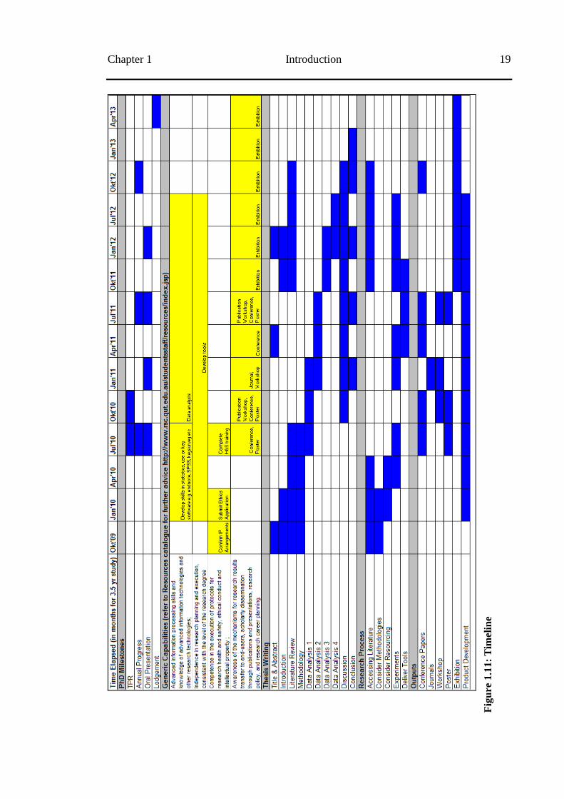
Chapter 1 Introduction 19
Fig
ure
1.1
1:
Tim
elin
e
20 1.6 Organisation of the Dissertation Chapter 1
1.6 Organisation of the Dissertation
This thesis was completed as part of a collaborative project between the Information Human
Centred Computing (iHcc) Group in the Research School of Computer Science (RSCS) at the
Australian National University and the Information Communication Technologies (ICT) Centre
at the Commonwealth Scientific and Industrial Research Organisation (CSIRO), with funding
provided from the Minerals Down Under (MDU) National Research Flagship.
This thesis consists of seven chapters: an introduction, a background on telerobotics and
related work that has been undertaken in this field; four chapters on the designed prototype, user
studies, evaluation, discussion, and a summary of the entire work in the conclusion. The
remainder of this dissertation is organised as follows:
Chapter 2 presents the literature review regarding the concepts of telerobotics systems,
interface design (e.g. the possibility of utilising the gaming environment for telerobotics user
interfaces) and control model (e.g. the possibility of improving the control model from one that
was based on direct/manual control to one that is based on HSC), including introducing related
research. This review also describes the MR environment, including types of current telerobotic
interfaces, and HSC - including the spectrum of current telerobotic control models. At the end
of this chapter, I demonstrate the communication implementation between a gaming
environment and a number of telerobots or simulation telerobot as initial gaming features
evaluation.
Chapters 3 to 6 provide descriptions of the whole evaluation and the experiments
including sub-experiments that were conducted during the research. These chapters discuss the
implemented prototype model for telerobotics systems MR and situated virtual model interfaces
and the combination of manual and supervisory control models.
Chapter 3 discusses the utilisation of a MR interface, which combines information from
streaming video and 3D generated computer visualisation, as telerobotics user interfaces. Based
on previous work in Chapter 2, the MR concept is applied to a number of gaming environments.
The experiment result was also analysed in relation to the operator‘s level of attention to the
telerobotic interfaces. This experiment is designed to compare the effectiveness of a MR
telerobotic interface in providing suitable information to the operator, as an alternative to
telerobotic user interface using streaming video or fully virtual interfaces.
Chapter 4 discusses a further evaluation of gaming engines in providing effective virtual
modelling where the object is adapted to the physical setting. I demonstrate the usage of a
scanner application in providing information of position and size of moving objects to build the
3D models. This chapter also shows the possibility of using the gaming environment to work
Chapter 1 Introduction 21
with other potential input devices for virtual camera movements. This chapter evaluate the user
performance of the improved model interfaces by closely adhering to the experimental settings
of Zhu et al‘s experiment [39].
Chapter 5 discusses the principle of HSC as a substitute for direct/manual control in
telerobotics to improve automation and reduce the dependence of human operators on the
system. The MR interfaces from the previous experiment in Chapter 4 are combined with the
HSC concepts. Besides focusing on the planning process which is one of the five generic
functions of HSC, the predictive and feedback information associated with the MR concept is
also explored in more detail in this chapter. There are two proposed response models for HSC
models which are tested. An experiment is designed to analyse the user performance of each
response model interface, including a sub experiment for direct/manual control as a comparison
study.
Chapter 6 provides an analysis using the Weibull distribution to evaluate the user
performance of the latest prototype telerobotics user interface. This evaluation data was
recorded from the implementation of the telerobotic system at a public exhibition held for a
period of three months. In this chapter, a Weibull model is applied with three parameters to
describe the observed sampling data from three model interfaces, including two interfaces for
the HSC response model and one interface for the direct/manual model. Two statistical model
approaches, the Chi-square goodness fit test and the Coefficient of determination test, are also
used to test the suitability of fitting the Weibull curve to the observed data.
Chapter 7 presents a conclusion of the whole evaluation and a discussion of the proposed
prototype telerobotics system. I determine the potential components/results from each chapter as
the benefits of our prototype telerobotic interfaces, such as: (1) whether a gaming engine is able
to be used as a basic environment for building telerobotic interfaces; (2) whether the MR
concept succeeds in providing missing information by using a combination of streaming video
and a situated VR environment; and (3) whether predictive display information, as a
combination of MR and HSC concepts, succeeds in reducing operator involvement and
decreases the effect of latency compared to direct/manual control. However, there are a number
of shortcomings of the proposed prototype due to the limitations of research time which I
describe in the suggestions and recommendations for potential further research, such as: (1) the
possibility to test the telerobotics user interface by using a wide variety of telerobotic scenarios,
including testing within a real telerobotic situation; (2) the possibility of utilising the multiuser
function for collaboration work; and (3) the possibility to improve the machines intelligence;
and (4) the possibility to evaluate other input devices and sensors.

22 1.6 Organisation of the Dissertation Chapter 1
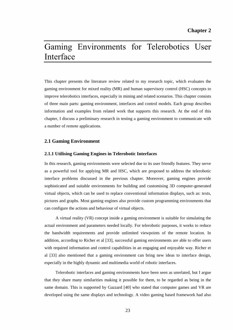
23
Chapter 2
Gaming Environments for Telerobotics User
Interface
This chapter presents the literature review related to my research topic, which evaluates the
gaming environment for mixed reality (MR) and human supervisory control (HSC) concepts to
improve telerobotics interfaces, especially in mining and related scenarios. This chapter consists
of three main parts: gaming environment, interfaces and control models. Each group describes
information and examples from related work that supports this research. At the end of this
chapter, I discuss a preliminary research in testing a gaming environment to communicate with
a number of remote applications.
2.1 Gaming Environment
2.1.1 Utilising Gaming Engines in Telerobotic Interfaces
In this research, gaming environments were selected due to its user friendly features. They serve
as a powerful tool for applying MR and HSC, which are proposed to address the telerobotic
interface problems discussed in the previous chapter. Moreover, gaming engines provide
sophisticated and suitable environments for building and customising 3D computer-generated
virtual objects, which can be used to replace conventional information displays, such as: texts,
pictures and graphs. Most gaming engines also provide custom programming environments that
can configure the actions and behaviour of virtual objects.
A virtual reality (VR) concept inside a gaming environment is suitable for simulating the
actual environment and parameters needed locally. For telerobotic purposes, it works to reduce
the bandwidth requirements and provide unlimited viewpoints of the remote location. In
addition, according to Richer et al [33], successful gaming environments are able to offer users
with required information and control capabilities in an engaging and enjoyable way. Richer et
al [33] also mentioned that a gaming environment can bring new ideas to interface design,
especially in the highly dynamic and multimedia world of robotic interfaces.
Telerobotic interfaces and gaming environments have been seen as unrelated, but I argue
that they share many similarities making it possible for them, to be regarded as being in the
same domain. This is supported by Gazzard [40] who stated that computer games and VR are
developed using the same displays and technology. A video gaming based framework had also
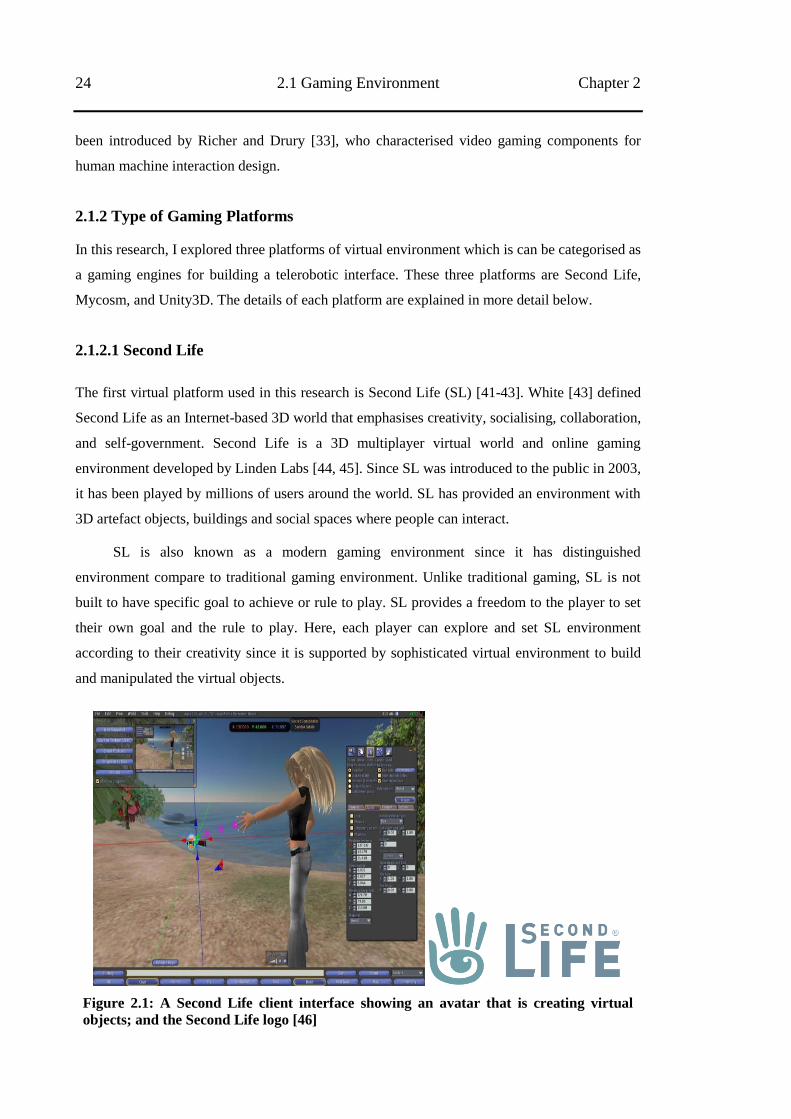
24 2.1 Gaming Environment Chapter 2
been introduced by Richer and Drury [33], who characterised video gaming components for
human machine interaction design.
2.1.2 Type of Gaming Platforms
In this research, I explored three platforms of virtual environment which is can be categorised as
a gaming engines for building a telerobotic interface. These three platforms are Second Life,
Mycosm, and Unity3D. The details of each platform are explained in more detail below.
2.1.2.1 Second Life
The first virtual platform used in this research is Second Life (SL) [41-43]. White [43] defined
Second Life as an Internet-based 3D world that emphasises creativity, socialising, collaboration,
and self-government. Second Life is a 3D multiplayer virtual world and online gaming
environment developed by Linden Labs [44, 45]. Since SL was introduced to the public in 2003,
it has been played by millions of users around the world. SL has provided an environment with
3D artefact objects, buildings and social spaces where people can interact.
SL is also known as a modern gaming environment since it has distinguished
environment compare to traditional gaming environment. Unlike traditional gaming, SL is not
built to have specific goal to achieve or rule to play. SL provides a freedom to the player to set
their own goal and the rule to play. Here, each player can explore and set SL environment
according to their creativity since it is supported by sophisticated virtual environment to build
and manipulated the virtual objects.
Figure 2.1: A Second Life client interface showing an avatar that is creating virtual
objects; and the Second Life logo [46]
Chapter 2 Gaming Environments for Telerobotics User Interface 25
SL provides a programming language, the Linden Scripting Language (LSL) [42]. Similar
to other programming languages, LSL consists of variables, library functions, constants, flow
control, and one or more named states. As a state-event driven scripting language, the state
contains a guide to behaviours based on events that occur when the program is in that state.
When the system sends commands to the script, the script will check for compatible events, and
is then able to change most aspects of the state of the object and communicate with other objects
as well as an avatar (replication of user in SL). As soon as a script is added into an object, it will
start to execute. As a multiuser gaming environment, SL has the ability to continue to run every
action or behaviour inside the script embedded in an object even when the owner user/avatar is
not logged in. In addition, any objects in the SL world can communicate with objects outside
the virtual world through the Internet via email, XML-RPC and HTTP requests.
For my research purpose, I used SL viewer (SL client interfaces) as a telerobotics
interface. The communication between the gaming interface and the telerobot is built through a
third party server, in this case refers to the SL online server. Figure 2.1 shows the
communication flow diagram among SL viewer as a telerobotic user interface, SL server as a
third party server, and telerobot.
Figure 2.2: Communication flow diagram between telerobotics interface and telerobot
through third party server
A number of advantages and disadvantages of using SL platform as telerobotic interfaces
can are summarised in Table 2.1.
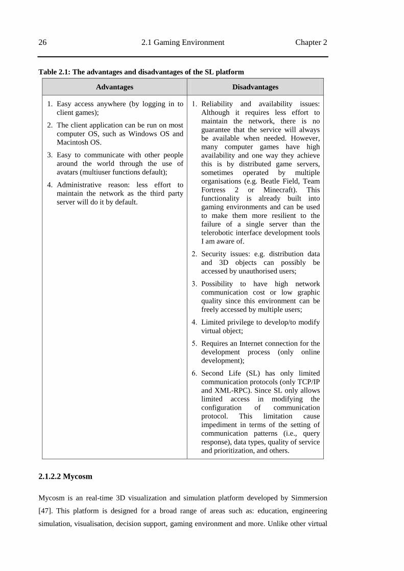
26 2.1 Gaming Environment Chapter 2
Table 2.1: The advantages and disadvantages of the SL platform
Advantages Disadvantages
1. Easy access anywhere (by logging in to
client games);
2. The client application can be run on most
computer OS, such as Windows OS and
Macintosh OS.
3. Easy to communicate with other people
around the world through the use of
avatars (multiuser functions default);
4. Administrative reason: less effort to
maintain the network as the third party
server will do it by default.
1. Reliability and availability issues:
Although it requires less effort to
maintain the network, there is no
guarantee that the service will always
be available when needed. However,
many computer games have high
availability and one way they achieve
this is by distributed game servers,
sometimes operated by multiple
organisations (e.g. Beatle Field, Team
Fortress 2 or Minecraft). This
functionality is already built into
gaming environments and can be used
to make them more resilient to the
failure of a single server than the
telerobotic interface development tools
I am aware of.
2. Security issues: e.g. distribution data
and 3D objects can possibly be
accessed by unauthorised users;
3. Possibility to have high network
communication cost or low graphic
quality since this environment can be
freely accessed by multiple users;
4. Limited privilege to develop/to modify
virtual object;
5. Requires an Internet connection for the
development process (only online
development);
6. Second Life (SL) has only limited
communication protocols (only TCP/IP
and XML-RPC). Since SL only allows
limited access in modifying the
configuration of communication
protocol. This limitation cause
impediment in terms of the setting of
communication patterns (i.e., query
response), data types, quality of service
and prioritization, and others.
2.1.2.2 Mycosm
Mycosm is an real-time 3D visualization and simulation platform developed by Simmersion
[47]. This platform is designed for a broad range of areas such as: education, engineering
simulation, visualisation, decision support, gaming environment and more. Unlike other virtual
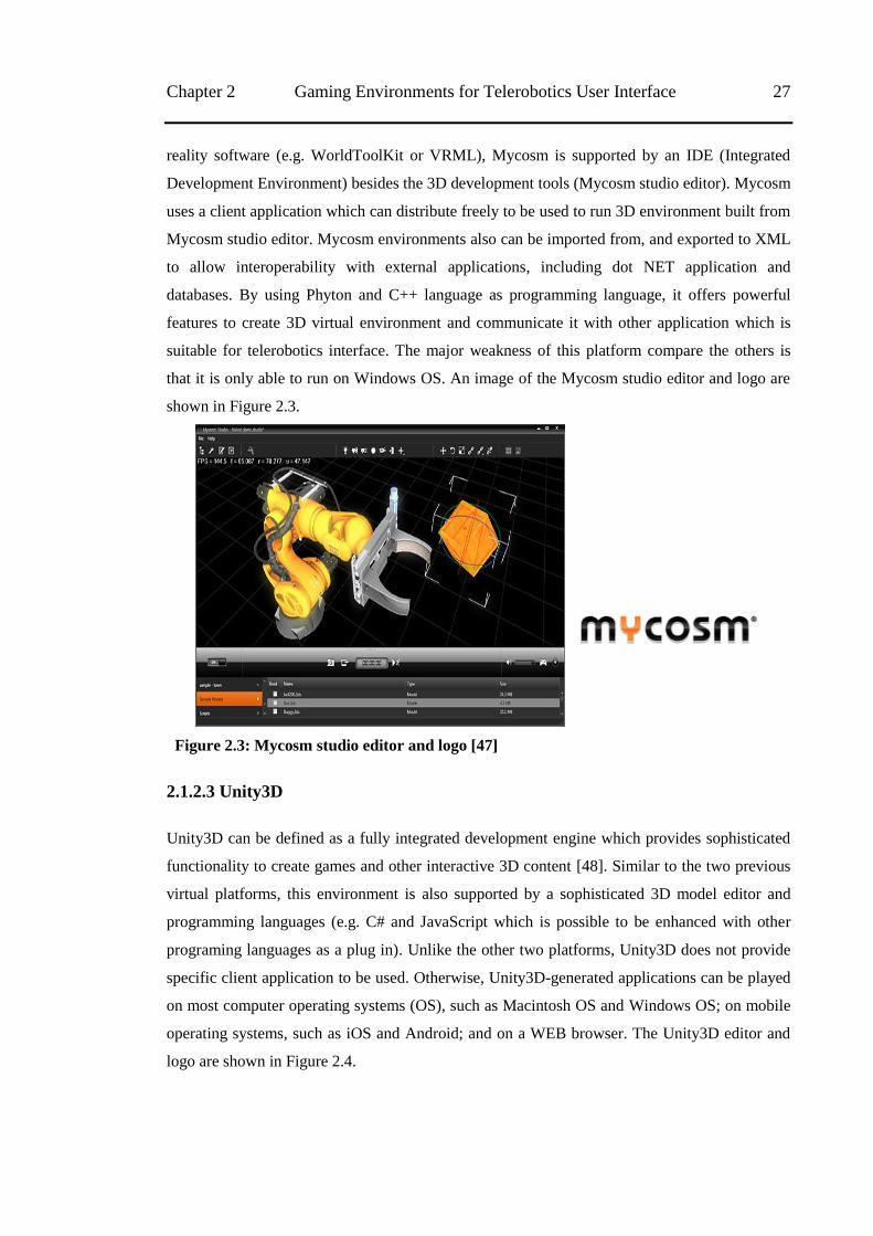
Chapter 2 Gaming Environments for Telerobotics User Interface 27
reality software (e.g. WorldToolKit or VRML), Mycosm is supported by an IDE (Integrated
Development Environment) besides the 3D development tools (Mycosm studio editor). Mycosm
uses a client application which can distribute freely to be used to run 3D environment built from
Mycosm studio editor. Mycosm environments also can be imported from, and exported to XML
to allow interoperability with external applications, including dot NET application and
databases. By using Phyton and C++ language as programming language, it offers powerful
features to create 3D virtual environment and communicate it with other application which is
suitable for telerobotics interface. The major weakness of this platform compare the others is
that it is only able to run on Windows OS. An image of the Mycosm studio editor and logo are
shown in Figure 2.3.
Figure 2.3: Mycosm studio editor and logo [47]
2.1.2.3 Unity3D
Unity3D can be defined as a fully integrated development engine which provides sophisticated
functionality to create games and other interactive 3D content [48]. Similar to the two previous
virtual platforms, this environment is also supported by a sophisticated 3D model editor and
programming languages (e.g. C# and JavaScript which is possible to be enhanced with other
programing languages as a plug in). Unlike the other two platforms, Unity3D does not provide
specific client application to be used. Otherwise, Unity3D-generated applications can be played
on most computer operating systems (OS), such as Macintosh OS and Windows OS; on mobile
operating systems, such as iOS and Android; and on a WEB browser. The Unity3D editor and
logo are shown in Figure 2.4.
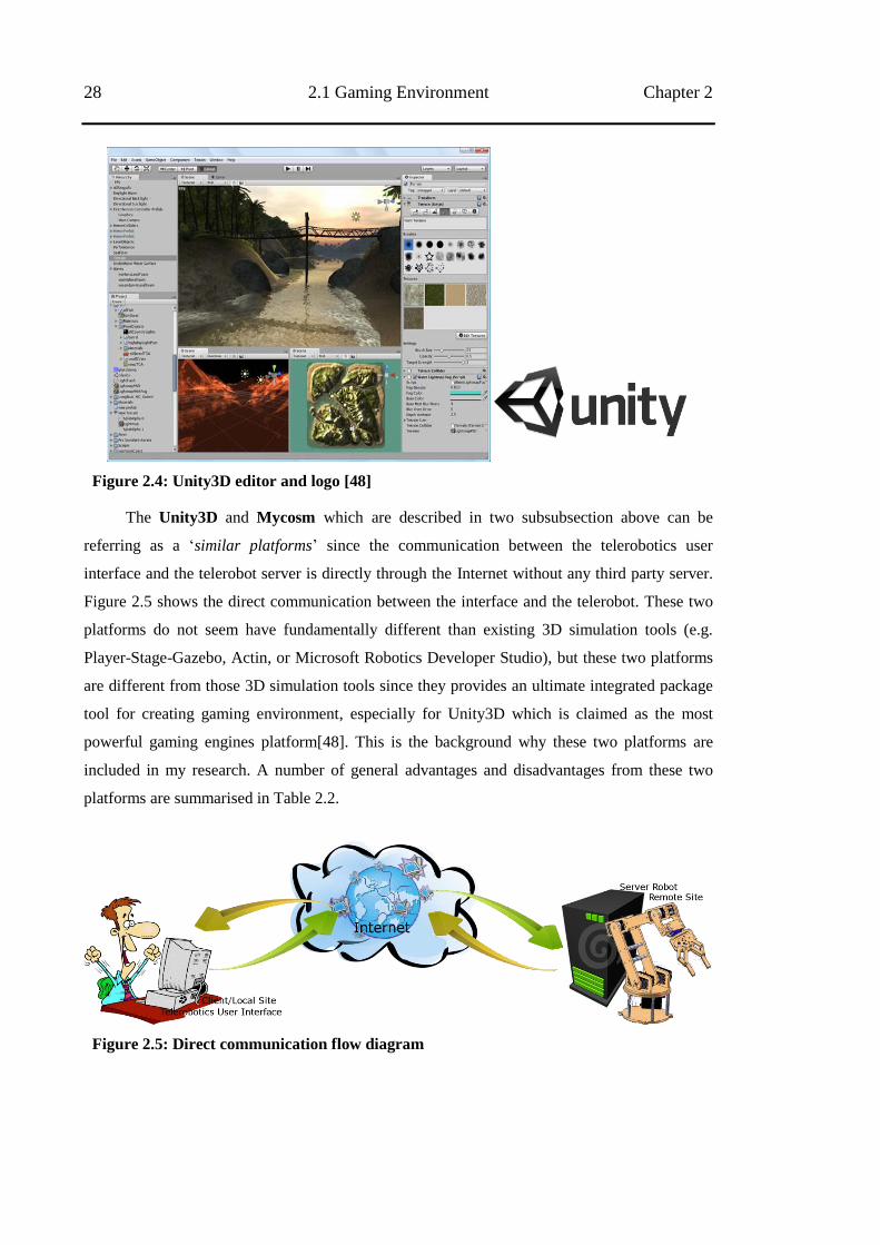
28 2.1 Gaming Environment Chapter 2
Figure 2.4: Unity3D editor and logo [48]
The Unity3D and Mycosm which are described in two subsubsection above can be
referring as a ‗similar platforms‘ since the communication between the telerobotics user
interface and the telerobot server is directly through the Internet without any third party server.
Figure 2.5 shows the direct communication between the interface and the telerobot. These two
platforms do not seem have fundamentally different than existing 3D simulation tools (e.g.
Player-Stage-Gazebo, Actin, or Microsoft Robotics Developer Studio), but these two platforms
are different from those 3D simulation tools since they provides an ultimate integrated package
tool for creating gaming environment, especially for Unity3D which is claimed as the most
powerful gaming engines platform[48]. This is the background why these two platforms are
included in my research. A number of general advantages and disadvantages from these two
platforms are summarised in Table 2.2.
Figure 2.5: Direct communication flow diagram
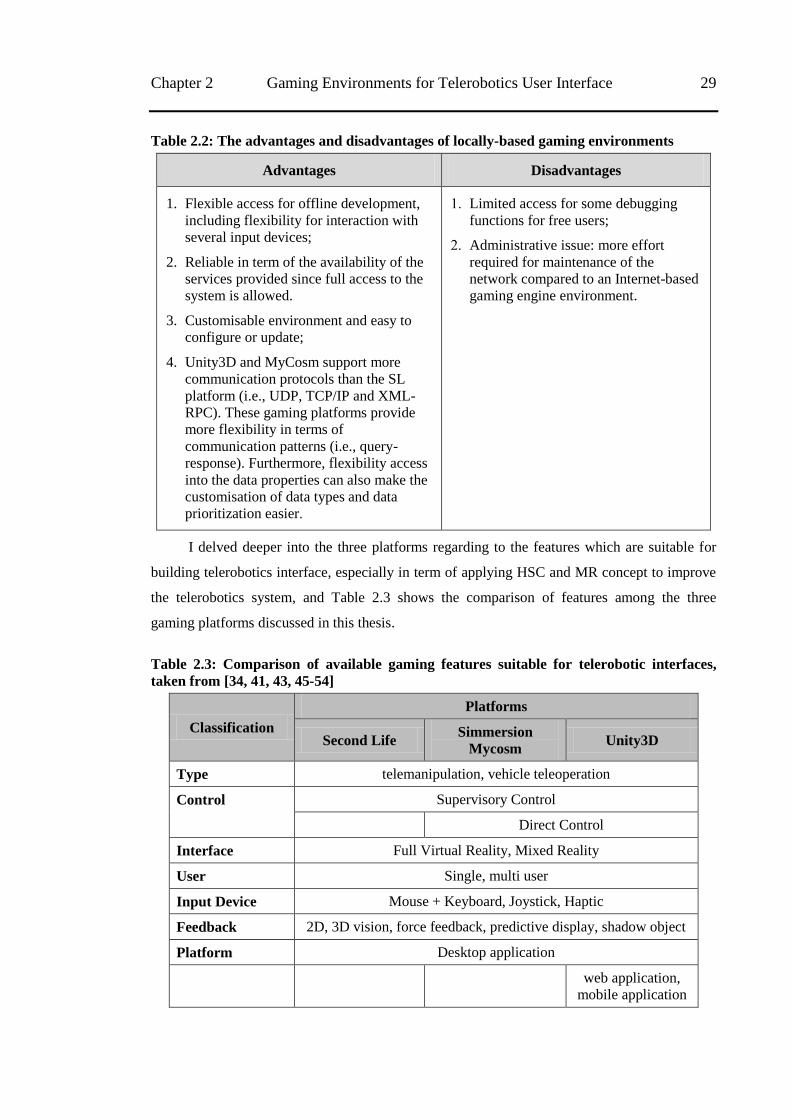
Chapter 2 Gaming Environments for Telerobotics User Interface 29
Table 2.2: The advantages and disadvantages of locally-based gaming environments
Advantages Disadvantages
1. Flexible access for offline development,
including flexibility for interaction with
several input devices;
2. Reliable in term of the availability of the
services provided since full access to the
system is allowed.
3. Customisable environment and easy to
configure or update;
4. Unity3D and MyCosm support more
communication protocols than the SL
platform (i.e., UDP, TCP/IP and XML-
RPC). These gaming platforms provide
more flexibility in terms of
communication patterns (i.e., query-
response). Furthermore, flexibility access
into the data properties can also make the
customisation of data types and data
prioritization easier.
1. Limited access for some debugging
functions for free users;
2. Administrative issue: more effort
required for maintenance of the
network compared to an Internet-based
gaming engine environment.
I delved deeper into the three platforms regarding to the features which are suitable for
building telerobotics interface, especially in term of applying HSC and MR concept to improve
the telerobotics system, and Table 2.3 shows the comparison of features among the three
gaming platforms discussed in this thesis.
Table 2.3: Comparison of available gaming features suitable for telerobotic interfaces,
taken from [34, 41, 43, 45-54]
Classification
Platforms
Second Life Simmersion
Mycosm Unity3D
Type telemanipulation, vehicle teleoperation
Control Supervisory Control
Direct Control
Interface Full Virtual Reality, Mixed Reality
User Single, multi user
Input Device Mouse + Keyboard, Joystick, Haptic
Feedback 2D, 3D vision, force feedback, predictive display, shadow object
Platform Desktop application
web application,
mobile application
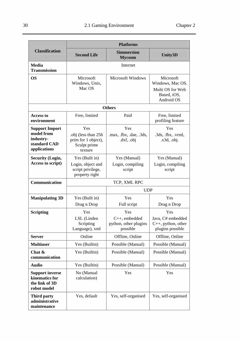
30 2.1 Gaming Environment Chapter 2
Classification
Platforms
Second Life Simmersion
Mycosm Unity3D
Media
Transmission
Internet
OS Microsoft
Windows, Unix,
Mac OS
Microsoft Windows Microsoft
Windows, Mac OS.
Multi OS for Web
Based, iOS,
Android OS
Others
Access to
environment
Free, limited Paid Free, limited
profiling feature
Support Import
model from
industry-
standard CAD
applications
Yes
.obj (less than 256
prim for 1 object),
Sculpt prime
texture
Yes
.max, .fbx, .dae, .3ds,
.dxf, .obj
Yes
.3ds, .fbx, .vrml,
.x3d, .obj.
Security (Login,
Access to script)
Yes (Built in)
Login, object and
script privilege,
property right
Yes (Manual)
Login, compiling
script
Yes (Manual)
Login, compiling
script
Communication TCP, XML RPC
UDP
Manipulating 3D Yes (Built in)
Drag n Drop
Yes
Full script
Yes
Drag n Drop
Scripting Yes
LSL (Linden
Scripting
Language), xml
Yes
C++, embedded
python, other plugins
possible
Yes
Java, C# embedded
C++, python, other
plugins possible
Server Online Offline, Online Offline, Online
Multiuser Yes (Builtin) Possible (Manual) Possible (Manual)
Chat &
communication
Yes (Builtin) Possible (Manual) Possible (Manual)
Audio Yes (Builtin) Possible (Manual) Possible (Manual)
Support inverse
kinematics for
the link of 3D
robot model
No (Manual
calculation)
Yes Yes
Third party
administrative
maintenance
Yes, default Yes, self-organised Yes, self-organised
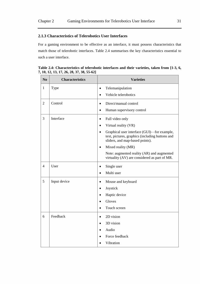
Chapter 2 Gaming Environments for Telerobotics User Interface 31
2.1.3 Characteristics of Telerobotics User Interfaces
For a gaming environment to be effective as an interface, it must possess characteristics that
match those of telerobotic interfaces. Table 2.4 summarises the key characteristics essential to
such a user interface.
Table 2.4: Characteristics of telerobotic interfaces and their varieties, taken from [1-3, 6,
7, 10, 12, 13, 17, 26, 28, 37, 38, 55-62]
No Characteristics Varieties
1 Type Telemanipulation
Vehicle telerobotics
2 Control Direct/manual control
Human supervisory control
3 Interface Full video only
Virtual reality (VR)
Graphical user interface (GUI)—for example,
text, pictures, graphics (including buttons and
sliders, and map-based points).
Mixed reality (MR)
Note: augmented reality (AR) and augmented
virtuality (AV) are considered as part of MR.
4 User Single user
Multi user
5 Input device Mouse and keyboard
Joystick
Haptic device
Gloves
Touch screen
6 Feedback 2D vision
3D vision
Audio
Force feedback
Vibration
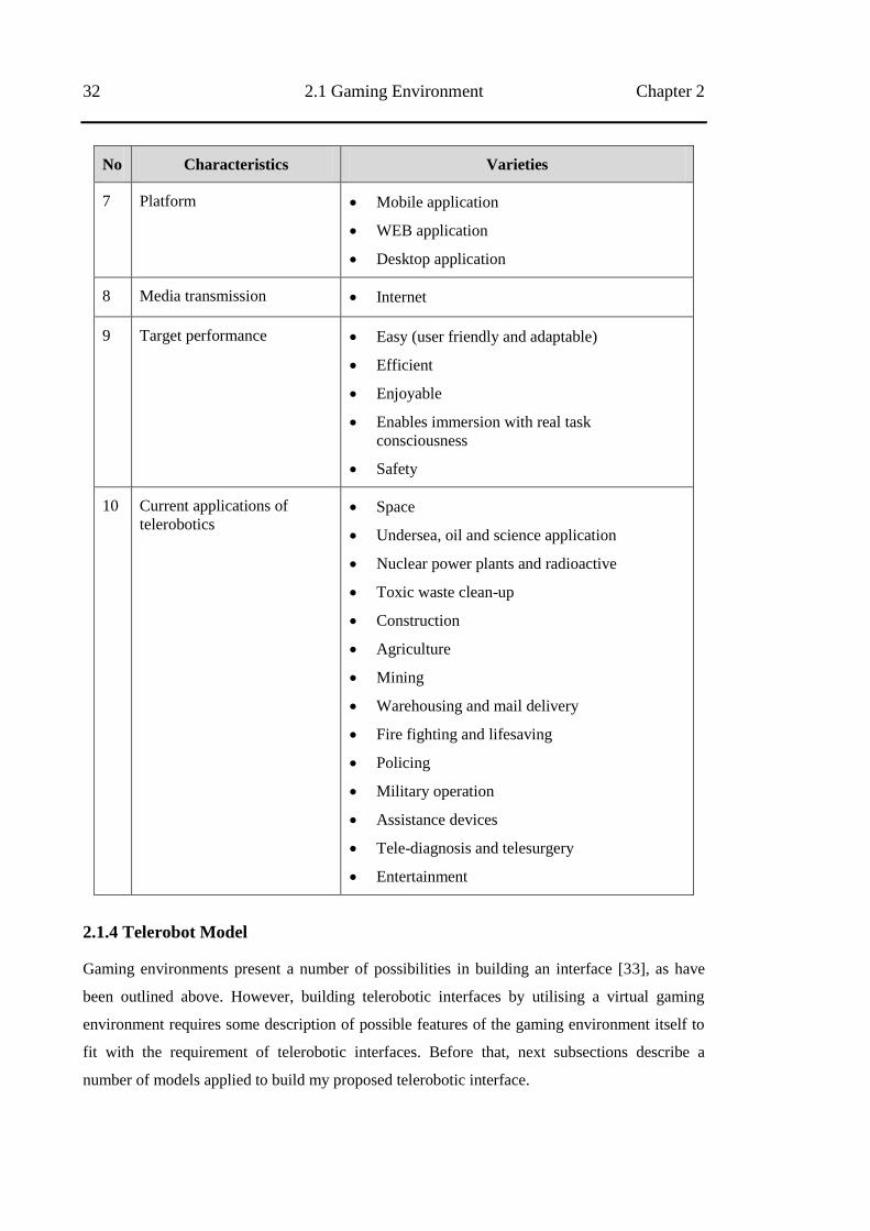
32 2.1 Gaming Environment Chapter 2
No Characteristics Varieties
7 Platform Mobile application
WEB application
Desktop application
8 Media transmission Internet
9 Target performance Easy (user friendly and adaptable)
Efficient
Enjoyable
Enables immersion with real task
consciousness
Safety
10 Current applications of
telerobotics Space
Undersea, oil and science application
Nuclear power plants and radioactive
Toxic waste clean-up
Construction
Agriculture
Mining
Warehousing and mail delivery
Fire fighting and lifesaving
Policing
Military operation
Assistance devices
Tele-diagnosis and telesurgery
Entertainment
2.1.4 Telerobot Model
Gaming environments present a number of possibilities in building an interface [33], as have
been outlined above. However, building telerobotic interfaces by utilising a virtual gaming
environment requires some description of possible features of the gaming environment itself to
fit with the requirement of telerobotic interfaces. Before that, next subsections describe a
number of models applied to build my proposed telerobotic interface.
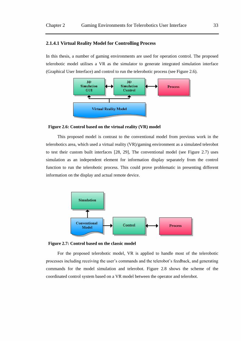
Chapter 2 Gaming Environments for Telerobotics User Interface 33
2.1.4.1 Virtual Reality Model for Controlling Process
In this thesis, a number of gaming environments are used for operation control. The proposed
telerobotic model utilises a VR as the simulator to generate integrated simulation interface
(Graphical User Interface) and control to run the telerobotic process (see Figure 2.6).
Figure 2.6: Control based on the virtual reality (VR) model
This proposed model is contrast to the conventional model from previous work in the
telerobotics area, which used a virtual reality (VR)/gaming environment as a simulated telerobot
to test their custom built interfaces [28, 29], The conventional model (see Figure 2.7) uses
simulation as an independent element for information display separately from the control
function to run the telerobotic process. This could prove problematic in presenting different
information on the display and actual remote device.
Figure 2.7: Control based on the classic model
For the proposed telerobotic model, VR is applied to handle most of the telerobotic
processes including receiving the user‘s commands and the telerobot‘s feedback, and generating
commands for the model simulation and telerobot. Figure 2.8 shows the scheme of the
coordinated control system based on a VR model between the operator and telerobot.
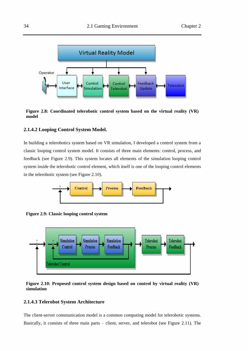
34 2.1 Gaming Environment Chapter 2
Figure 2.8: Coordinated telerobotic control system based on the virtual reality (VR)
model
2.1.4.2 Looping Control System Model.
In building a telerobotics system based on VR simulation, I developed a control system from a
classic looping control system model. It consists of three main elements: control, process, and
feedback (see Figure 2.9). This system locates all elements of the simulation looping control
system inside the telerobotic control element, which itself is one of the looping control elements
in the telerobotic system (see Figure 2.10).
Figure 2.9: Classic looping control system
Figure 2.10: Proposed control system design based on control by virtual reality (VR)
simulation
2.1.4.3 Telerobot System Architecture
The client-server communication model is a common computing model for telerobotic systems.
Basically, it consists of three main parts – client, server, and telerobot (see Figure 2.11). The
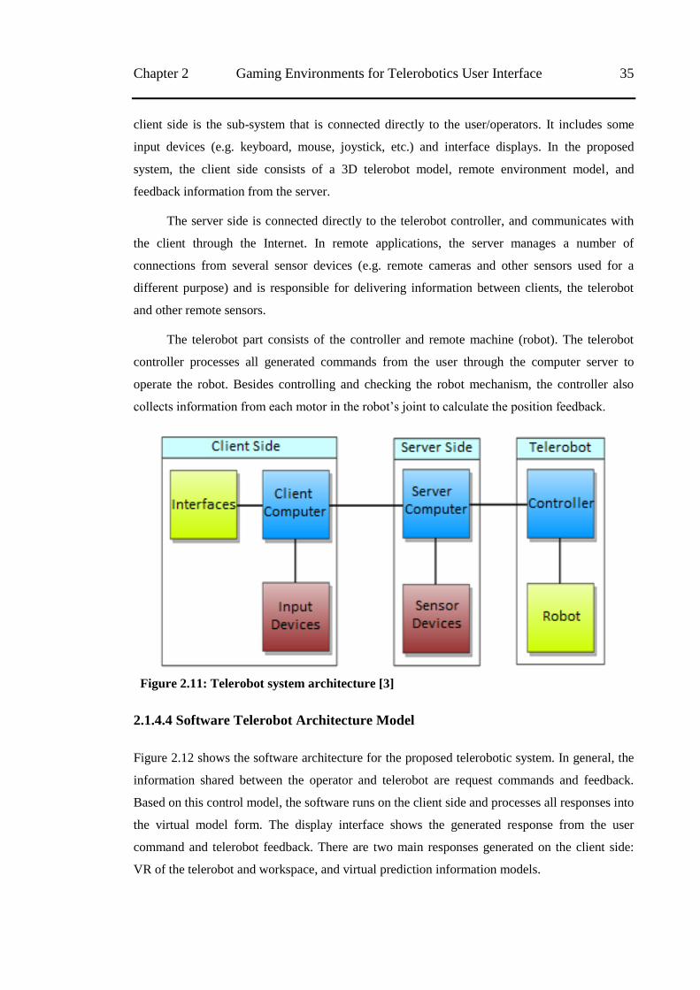
Chapter 2 Gaming Environments for Telerobotics User Interface 35
client side is the sub-system that is connected directly to the user/operators. It includes some
input devices (e.g. keyboard, mouse, joystick, etc.) and interface displays. In the proposed
system, the client side consists of a 3D telerobot model, remote environment model, and
feedback information from the server.
The server side is connected directly to the telerobot controller, and communicates with
the client through the Internet. In remote applications, the server manages a number of
connections from several sensor devices (e.g. remote cameras and other sensors used for a
different purpose) and is responsible for delivering information between clients, the telerobot
and other remote sensors.
The telerobot part consists of the controller and remote machine (robot). The telerobot
controller processes all generated commands from the user through the computer server to
operate the robot. Besides controlling and checking the robot mechanism, the controller also
collects information from each motor in the robot‘s joint to calculate the position feedback.
Figure 2.11: Telerobot system architecture [3]
2.1.4.4 Software Telerobot Architecture Model
Figure 2.12 shows the software architecture for the proposed telerobotic system. In general, the
information shared between the operator and telerobot are request commands and feedback.
Based on this control model, the software runs on the client side and processes all responses into
the virtual model form. The display interface shows the generated response from the user
command and telerobot feedback. There are two main responses generated on the client side:
VR of the telerobot and workspace, and virtual prediction information models.
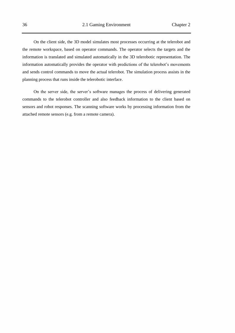
36 2.1 Gaming Environment Chapter 2
On the client side, the 3D model simulates most processes occurring at the telerobot and
the remote workspace, based on operator commands. The operator selects the targets and the
information is translated and simulated automatically in the 3D telerobotic representation. The
information automatically provides the operator with predictions of the telerobot‘s movements
and sends control commands to move the actual telerobot. The simulation process assists in the
planning process that runs inside the telerobotic interface.
On the server side, the server‘s software manages the process of delivering generated
commands to the telerobot controller and also feedback information to the client based on
sensors and robot responses. The scanning software works by processing information from the
attached remote sensors (e.g. from a remote camera).
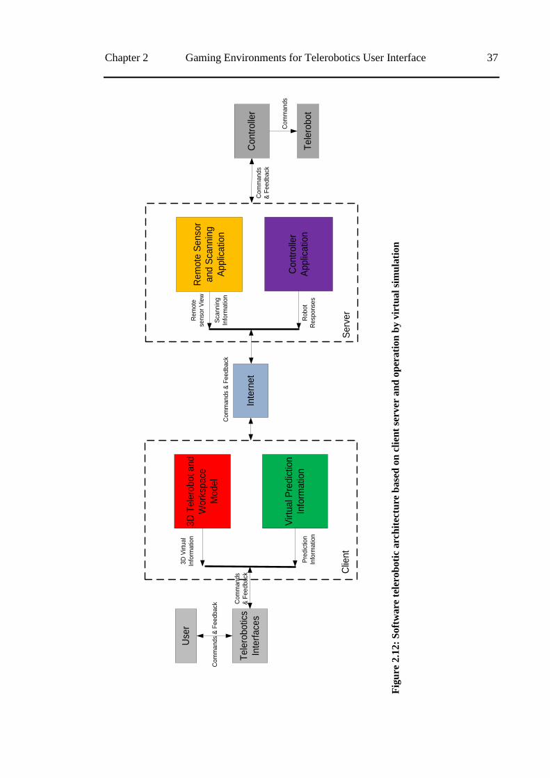
Chapter 2 Gaming Environments for Telerobotics User Interface 37
Use
r
Te
lero
bo
tics
Inte
rfa
ces
3D
Te
lero
bo
t a
nd
Wo
rksp
ace
Mo
de
l
Virtu
al P
red
ictio
n
Info
rma
tion
3D
Virtu
al
Info
rma
tion
Pre
dic
tion
Info
rma
tion
Clie
nt
Inte
rne
t
Re
mo
te S
en
sor
an
d S
can
nin
g
Ap
plic
atio
n
Co
ntr
olle
r
Ap
plic
atio
n
Re
mo
te
sen
sor
Vie
w
Sca
nn
ing
Info
rma
tion
Ro
bo
t
Re
spo
nse
s
Se
rve
r
Co
ntr
olle
r
Te
lero
bo
t
Co
mm
an
ds
& F
ee
db
ack
Co
mm
an
ds
& F
ee
db
ack
Co
mm
an
ds
& F
ee
db
ack
Co
mm
an
ds
& F
ee
db
ack
Co
mm
an
ds
Fig
ure
2.1
2:
So
ftw
are
tel
ero
bo
tic
arc
hit
ectu
re b
ase
d o
n c
lien
t se
rver
an
d o
per
ati
on
by v
irtu
al
sim
ula
tio
n
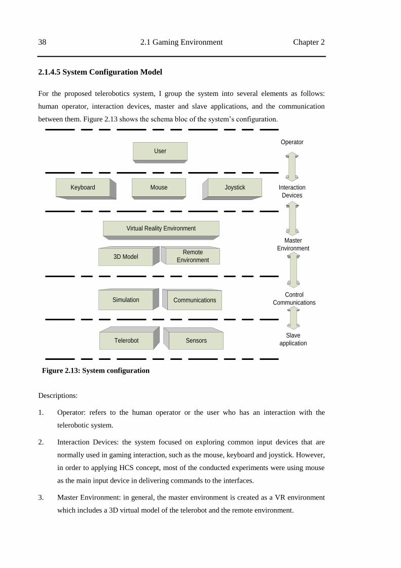
38 2.1 Gaming Environment Chapter 2
2.1.4.5 System Configuration Model
For the proposed telerobotics system, I group the system into several elements as follows:
human operator, interaction devices, master and slave applications, and the communication
between them. Figure 2.13 shows the schema bloc of the system‘s configuration.
Keyboard Mouse Joystick
3D Model
Virtual Reality Environment
Remote
Environment
Simulation Communications
Telerobot Sensors
Operator
Interaction
Devices
Master
Environment
Control
Communications
Slave
application
User
Figure 2.13: System configuration
Descriptions:
1. Operator: refers to the human operator or the user who has an interaction with the
telerobotic system.
2. Interaction Devices: the system focused on exploring common input devices that are
normally used in gaming interaction, such as the mouse, keyboard and joystick. However,
in order to applying HCS concept, most of the conducted experiments were using mouse
as the main input device in delivering commands to the interfaces.
3. Master Environment: in general, the master environment is created as a VR environment
which includes a 3D virtual model of the telerobot and the remote environment.
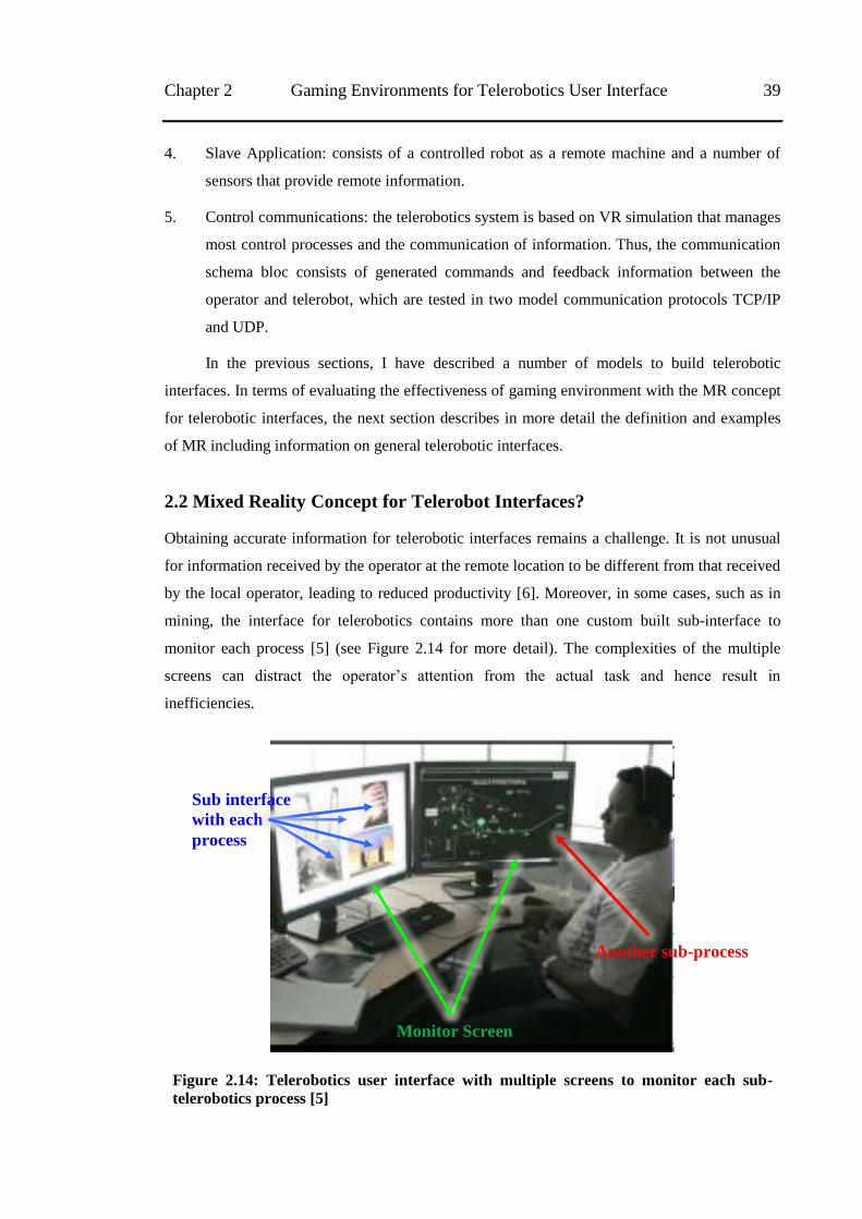
Chapter 2 Gaming Environments for Telerobotics User Interface 39
4. Slave Application: consists of a controlled robot as a remote machine and a number of
sensors that provide remote information.
5. Control communications: the telerobotics system is based on VR simulation that manages
most control processes and the communication of information. Thus, the communication
schema bloc consists of generated commands and feedback information between the
operator and telerobot, which are tested in two model communication protocols TCP/IP
and UDP.
In the previous sections, I have described a number of models to build telerobotic
interfaces. In terms of evaluating the effectiveness of gaming environment with the MR concept
for telerobotic interfaces, the next section describes in more detail the definition and examples
of MR including information on general telerobotic interfaces.
2.2 Mixed Reality Concept for Telerobot Interfaces?
Obtaining accurate information for telerobotic interfaces remains a challenge. It is not unusual
for information received by the operator at the remote location to be different from that received
by the local operator, leading to reduced productivity [6]. Moreover, in some cases, such as in
mining, the interface for telerobotics contains more than one custom built sub-interface to
monitor each process [5] (see Figure 2.14 for more detail). The complexities of the multiple
screens can distract the operator‘s attention from the actual task and hence result in
inefficiencies.
Figure 2.14: Telerobotics user interface with multiple screens to monitor each sub-
telerobotics process [5]
Monitor Screen
Sub interface
with each
process
Another sub-process
40 2.2 Mixed Reality Concept for Telerobot Interfaces? Chapter 2
An important aspect of telerobotics is situational awareness (SA). Situational awareness
is defined as the perception of complex environmental elements with respect to time or space. It
plays a significant role in telerobotics and is critical for decision makers [63]. In a telerobotic
scenario, where the operator has limited information concerning the remote situation compared
to an operator with direct onsite control, the role of the interface is to provide adequate
information to complete the task, using simple visualisations from the remote location.
MR is able to harness the strengths of both the virtual reality model and video streaming
in its delivery of information [64]. It can be used with simple displays without any loss of
necessary information compared to the use of multiple streaming video. Hence I argue that
integrating MR environments into telerobotic interfaces can provide most of the information the
operator requires to perform the task.
Before discussing in more detail the MR concept for telerobotic interfaces, and how this
concept provides all the information required, it is necessary to understand the current
technology of existing interfaces. The next section describes telerobotic interfaces.
2.2.1 Telerobot Interfaces
Interfaces play an important role in providing information to the operator in a telerobotics
system. An interface should also be designed to be user friendly, efficient and reliable.
Therefore, two essential points should be taken into consideration when developing interfaces:
the process of controlling/operating and observing/monitoring.
In describing the various forms of interfaces, based on the two essential points above,
Fong and Thorpe [1] categorised the interfaces into four groups: direct interface, supervisory
control interface, multimodal interface, and novel interface. The direct and supervisory control
interfaces are a group of interfaces that are categorised by their control model, whereas a
multimodal interface is a group of interfaces which are categorised based on the usage of more
than one remote sensor to provide information. Besides the three categories of interfaces
mentioned above, the other interfaces can be classified into the novel interfaces group.
Examples of novel interfaces, related with telerobotics, include:
a. interfaces with particular input devices:
(1) by using muscle and brainwave movement monitors for hands-free remote driving
interfaces [27],
(2) by using a Haptic feedback device for remote control devices [25, 26],
(3) by using a Wii sensor as a Gesture Driver [65], and
Chapter 2 Gaming Environments for Telerobotics User Interface 41
(4) by using head and gaze tracking for a telerobotics camera control interface [66];
b. interfaces for particular platforms:
(1) WEB-based platform for telerobotics [67], and
(2) Personal Data Assistant (PDA) devices for remote driving control [7].
The interfaces can also be classified into three groups based on the type of information
provided. These classifications will be explained in more detail in the following sub-sections.
2.2.1.1 Video Interfaces
The first classification is the video interface. Common telerobotic interfaces utilise image
transmission from remote cameras over the Internet, via live video/streaming video. In a short
distance telerobotics scenario, Massimino and Sheridan [68] mentioned that the video interface
could provide information to the operator as well as if they were using their direct vision.
Through simple block insertion task, Massimino and Sheridan successfully compared remote
operation via direct operator vision and through video interface and found that there was no
significant differences between direct viewing and seeing through video interfaces, when the
total visual field object to be manipulated was the same.
Video interfaces suffer from some limitations. Firstly, the usual fixed-position of remote
cameras restricts their range of vision, making exploring the remote environment difficult,
despite the pan, tilt and zoom functions. Secondly, real-time image transmission with high
resolution requires high bandwidth. Images from video interfaces can suffer from other
problems, including spatial resolution, signal noise and distortion. Thirdly, the instability of the
Internet connection including network delays in data transmission severely limits real-time
control and feedback, particularly when there is more than one camera installed. Fourthly, when
using a single camera, the method transmits two-dimensional (2D) images. It is difficult for the
operator to visualise the object‘s position in a single projector line. Fourthly, when using a
single video camera, the method transmits two-dimensional (2D) images. It is difficult for the
operator to visualise the object‘s position in a single projector line. While a stereo video system
can achieve 3D visualisation easily, it can only do this from a static single viewpoint. On the
other hand, a virtual camera offers the operator freedom to view the object from any direction.
Figure 2.15 shows that any point on the projector line between A and A‘ is projected as
A‘ on the projection plane (2D screen monitor), and similarly any point between B and B‘ is
projected as B‘. The fifth issue is the high cost of producing bespoke telerobotics user
interfaces.
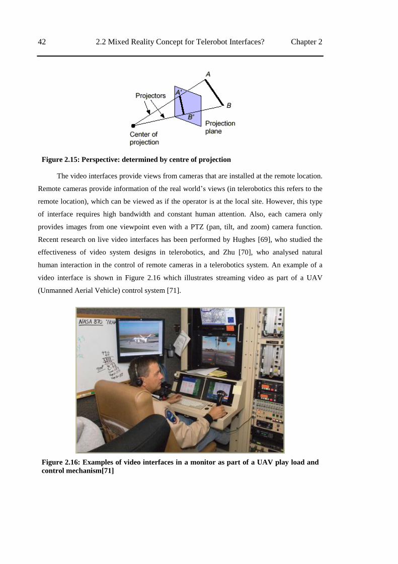
42 2.2 Mixed Reality Concept for Telerobot Interfaces? Chapter 2
Figure 2.15: Perspective: determined by centre of projection
The video interfaces provide views from cameras that are installed at the remote location.
Remote cameras provide information of the real world‘s views (in telerobotics this refers to the
remote location), which can be viewed as if the operator is at the local site. However, this type
of interface requires high bandwidth and constant human attention. Also, each camera only
provides images from one viewpoint even with a PTZ (pan, tilt, and zoom) camera function.
Recent research on live video interfaces has been performed by Hughes [69], who studied the
effectiveness of video system designs in telerobotics, and Zhu [70], who analysed natural
human interaction in the control of remote cameras in a telerobotics system. An example of a
video interface is shown in Figure 2.16 which illustrates streaming video as part of a UAV
(Unmanned Aerial Vehicle) control system [71].
Figure 2.16: Examples of video interfaces in a monitor as part of a UAV play load and
control mechanism[71]
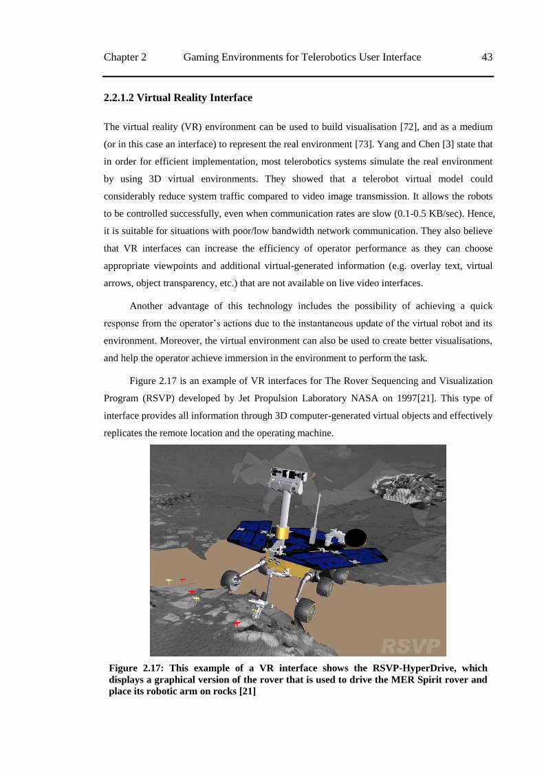
Chapter 2 Gaming Environments for Telerobotics User Interface 43
2.2.1.2 Virtual Reality Interface
The virtual reality (VR) environment can be used to build visualisation [72], and as a medium
(or in this case an interface) to represent the real environment [73]. Yang and Chen [3] state that
in order for efficient implementation, most telerobotics systems simulate the real environment
by using 3D virtual environments. They showed that a telerobot virtual model could
considerably reduce system traffic compared to video image transmission. It allows the robots
to be controlled successfully, even when communication rates are slow (0.1-0.5 KB/sec). Hence,
it is suitable for situations with poor/low bandwidth network communication. They also believe
that VR interfaces can increase the efficiency of operator performance as they can choose
appropriate viewpoints and additional virtual-generated information (e.g. overlay text, virtual
arrows, object transparency, etc.) that are not available on live video interfaces.
Another advantage of this technology includes the possibility of achieving a quick
response from the operator‘s actions due to the instantaneous update of the virtual robot and its
environment. Moreover, the virtual environment can also be used to create better visualisations,
and help the operator achieve immersion in the environment to perform the task.
Figure 2.17 is an example of VR interfaces for The Rover Sequencing and Visualization
Program (RSVP) developed by Jet Propulsion Laboratory NASA on 1997[21]. This type of
interface provides all information through 3D computer-generated virtual objects and effectively
replicates the remote location and the operating machine.
Figure 2.17: This example of a VR interface shows the RSVP-HyperDrive, which
displays a graphical version of the rover that is used to drive the MER Spirit rover and
place its robotic arm on rocks [21]
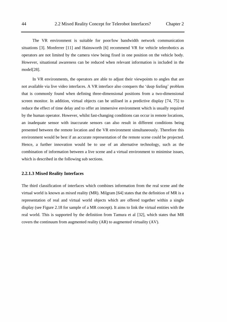
44 2.2 Mixed Reality Concept for Telerobot Interfaces? Chapter 2
The VR environment is suitable for poor/low bandwidth network communication
situations [3]. Monferrer [11] and Hainsworth [6] recommend VR for vehicle telerobotics as
operators are not limited by the camera view being fixed in one position on the vehicle body.
However, situational awareness can be reduced when relevant information is included in the
model[28].
In VR environments, the operators are able to adjust their viewpoints to angles that are
not available via live video interfaces. A VR interface also conquers the ‗deep feeling‘ problem
that is commonly found when defining three-dimensional positions from a two-dimensional
screen monitor. In addition, virtual objects can be utilised in a predictive display [74, 75] to
reduce the effect of time delay and to offer an immersive environment which is usually required
by the human operator. However, whilst fast-changing conditions can occur in remote locations,
an inadequate sensor with inaccurate sensors can also result in different conditions being
presented between the remote location and the VR environment simultaneously. Therefore this
environment would be best if an accurate representation of the remote scene could be projected.
Hence, a further innovation would be to use of an alternative technology, such as the
combination of information between a live scene and a virtual environment to minimise issues,
which is described in the following sub sections.
2.2.1.3 Mixed Reality Interfaces
The third classification of interfaces which combines information from the real scene and the
virtual world is known as mixed reality (MR). Milgram [64] states that the definition of MR is a
representation of real and virtual world objects which are offered together within a single
display (see Figure 2.18 for sample of a MR concept). It aims to link the virtual entities with the
real world. This is supported by the definition from Tamura et al [32], which states that MR
covers the continuum from augmented reality (AR) to augmented virtuality (AV).
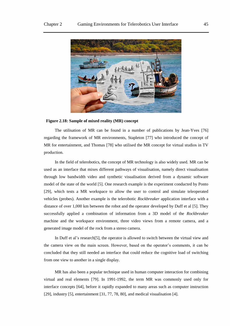
Chapter 2 Gaming Environments for Telerobotics User Interface 45
Figure 2.18: Sample of mixed reality (MR) concept
The utilisation of MR can be found in a number of publications by Jean-Yves [76]
regarding the framework of MR environments, Stapleton [77] who introduced the concept of
MR for entertainment, and Thomas [78] who utilised the MR concept for virtual studios in TV
production.
In the field of telerobotics, the concept of MR technology is also widely used. MR can be
used as an interface that mixes different pathways of visualisation, namely direct visualisation
through low bandwidth video and synthetic visualisation derived from a dynamic software
model of the state of the world [5]. One research example is the experiment conducted by Ponto
[29], which tests a MR workspace to allow the user to control and simulate teleoperated
vehicles (probes). Another example is the telerobotic Rockbreaker application interface with a
distance of over 1,000 km between the robot and the operator developed by Duff et al [5]. They
successfully applied a combination of information from a 3D model of the Rockbreaker
machine and the workspace environment, three video views from a remote camera, and a
generated image model of the rock from a stereo camera.
In Duff et al‘s research[5], the operator is allowed to switch between the virtual view and
the camera view on the main screen. However, based on the operator‘s comments, it can be
concluded that they still needed an interface that could reduce the cognitive load of switching
from one view to another in a single display.
MR has also been a popular technique used in human computer interaction for combining
virtual and real elements [79]. In 1991-1992, the term MR was commonly used only for
interface concepts [64], before it rapidly expanded to many areas such as computer instruction
[29], industry [5], entertainment [31, 77, 78, 80], and medical visualisation [4].
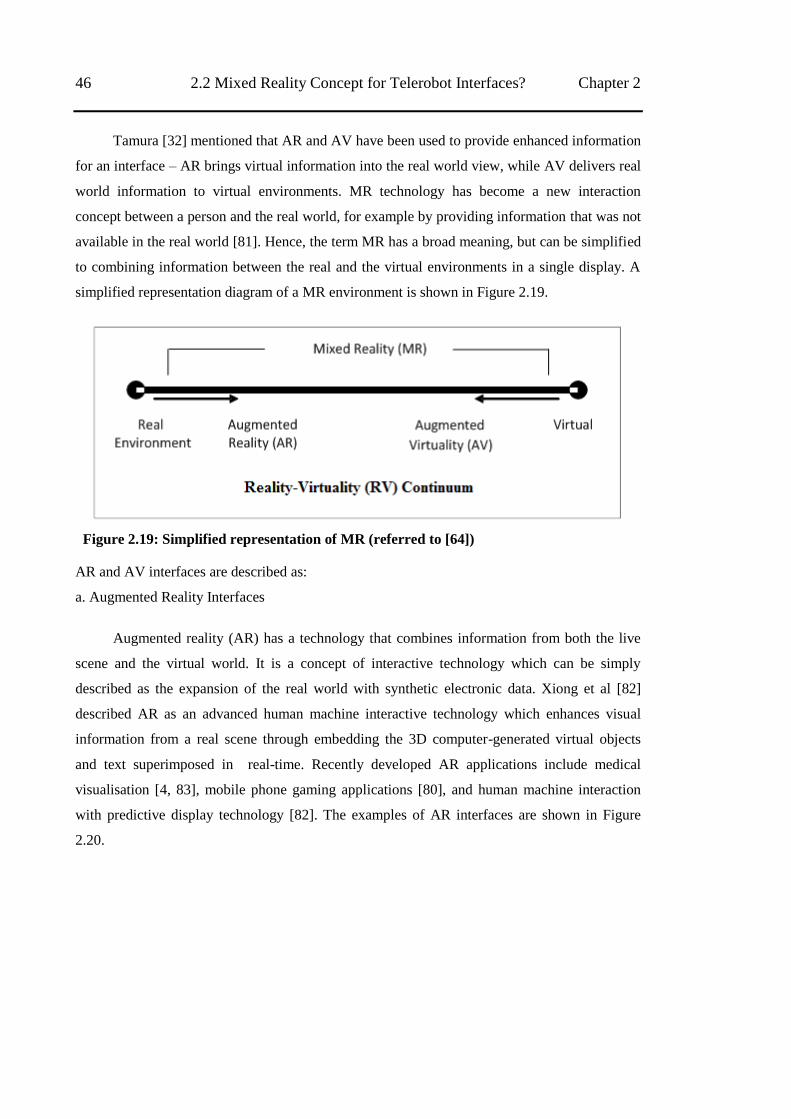
46 2.2 Mixed Reality Concept for Telerobot Interfaces? Chapter 2
Tamura [32] mentioned that AR and AV have been used to provide enhanced information
for an interface – AR brings virtual information into the real world view, while AV delivers real
world information to virtual environments. MR technology has become a new interaction
concept between a person and the real world, for example by providing information that was not
available in the real world [81]. Hence, the term MR has a broad meaning, but can be simplified
to combining information between the real and the virtual environments in a single display. A
simplified representation diagram of a MR environment is shown in Figure 2.19.
Figure 2.19: Simplified representation of MR (referred to [64])
AR and AV interfaces are described as:
a. Augmented Reality Interfaces
Augmented reality (AR) has a technology that combines information from both the live
scene and the virtual world. It is a concept of interactive technology which can be simply
described as the expansion of the real world with synthetic electronic data. Xiong et al [82]
described AR as an advanced human machine interactive technology which enhances visual
information from a real scene through embedding the 3D computer-generated virtual objects
and text superimposed in real-time. Recently developed AR applications include medical
visualisation [4, 83], mobile phone gaming applications [80], and human machine interaction
with predictive display technology [82]. The examples of AR interfaces are shown in Figure
2.20.
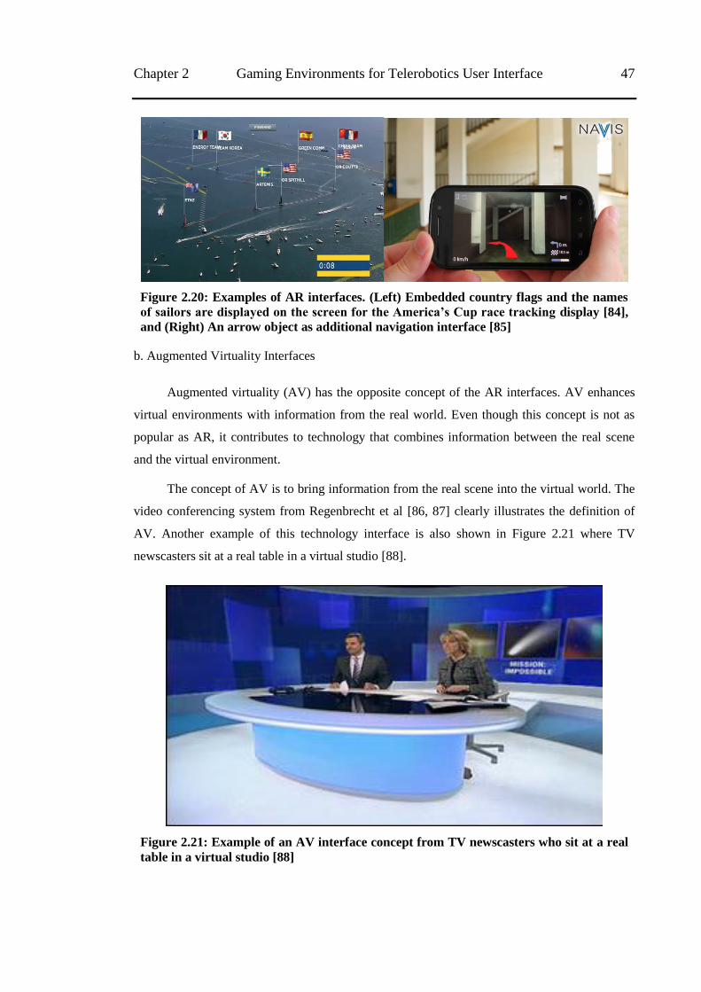
Chapter 2 Gaming Environments for Telerobotics User Interface 47
Figure 2.20: Examples of AR interfaces. (Left) Embedded country flags and the names
of sailors are displayed on the screen for the America‟s Cup race tracking display [84],
and (Right) An arrow object as additional navigation interface [85]
b. Augmented Virtuality Interfaces
Augmented virtuality (AV) has the opposite concept of the AR interfaces. AV enhances
virtual environments with information from the real world. Even though this concept is not as
popular as AR, it contributes to technology that combines information between the real scene
and the virtual environment.
The concept of AV is to bring information from the real scene into the virtual world. The
video conferencing system from Regenbrecht et al [86, 87] clearly illustrates the definition of
AV. Another example of this technology interface is also shown in Figure 2.21 where TV
newscasters sit at a real table in a virtual studio [88].
Figure 2.21: Example of an AV interface concept from TV newscasters who sit at a real
table in a virtual studio [88]
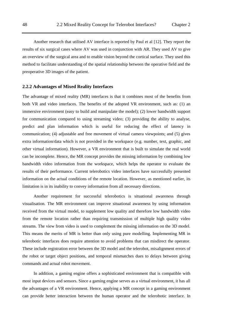
48 2.2 Mixed Reality Concept for Telerobot Interfaces? Chapter 2
Another research that utilised AV interface is reported by Paul et al [12]. They report the
results of six surgical cases where AV was used in conjunction with AR. They used AV to give
an overview of the surgical area and to enable vision beyond the cortical surface. They used this
method to facilitate understanding of the spatial relationship between the operative field and the
preoperative 3D images of the patient.
2.2.2 Advantages of Mixed Reality Interfaces
The advantage of mixed reality (MR) interfaces is that it combines most of the benefits from
both VR and video interfaces. The benefits of the adopted VR environment, such as: (1) an
immersive environment (easy to build and manipulate the model); (2) lower bandwidth support
for communication compared to using streaming video; (3) providing the ability to analyse,
predict and plan information which is useful for reducing the effect of latency in
communication; (4) adjustable and free movement of virtual camera viewpoints; and (5) gives
extra information/data which is not provided in the workspace (e.g. number, text, graphic, and
other virtual information). However, a VR environment that is built to simulate the real world
can be incomplete. Hence, the MR concept provides the missing information by combining low
bandwidth video information from the workspace, which helps the operator to evaluate the
results of their performance. Current telerobotics video interfaces have successfully presented
information on the actual conditions of the remote location. However, as mentioned earlier, its
limitation is in its inability to convey information from all necessary directions.
Another requirement for successful telerobotics is situational awareness through
visualisation. The MR environment can improve situational awareness by using information
received from the virtual model, to supplement low quality and therefore low bandwidth video
from the remote location rather than requiring transmission of multiple high quality video
streams. The view from video is used to complement the missing information on the 3D model.
This means the merits of MR is better than only using pure modelling. Implementing MR in
telerobotic interfaces does require attention to avoid problems that can misdirect the operator.
These include registration error between the 3D model and the telerobot, misalignment errors of
the robot or target object positions, and temporal mismatches dues to delays between giving
commands and actual robot movement.
In addition, a gaming engine offers a sophisticated environment that is compatible with
most input devices and sensors. Since a gaming engine serves as a virtual environment, it has all
the advantages of a VR environment. Hence, applying a MR concept in a gaming environment
can provide better interaction between the human operator and the telerobotic interface. In
Chapter 2 Gaming Environments for Telerobotics User Interface 49
addition, combining both sources of information (virtual model and video) in a single screen can
reduce cognitive load cause by diversion of the operator‘s attention between multiple screens.
Despite of the ability of MR in enhancing information to the operators, there is no
guarantee that MR interfaces can be better for user performance compared to other types of
interfaces. In addition, providing all information on one single screen can possibly lead to
confusion for the human operator and hence result in lower performance. In this chapter the
results from the application of the MR interface in a telerobotic scenario are discussed.
2.2.3 Design of Mixed Reality Interface in Gaming Environment
Most current telerobotic systems, especially those used in mining, contain a number of custom-
built user interfaces. Typically one interface for each mining process, which needs to be
monitored by the operator; hence an alternative, to reduce the cognitive load of switching from
one interface to another, is to present the operator with a single interface. Besides that, the
telerobotic interface should be interactive and reconfigurable, which can be achieved by using
platforms built for creating virtual games environments.
The basic environment of the proposed interface is a ‗VR in a gaming environment‘ with
augmented streaming video (see Figure 2.22). Information from streaming video was brought
into a virtual world to give information on a remote location. I used the LiSA (Localization and
Semantics of Assistance) model as a basis for the experiment design. This is a common model
in telerobotics systems, which defines a relationship between the operator, interface, network
systems, manipulator, and environment. This model can also be used to describe a VR system
that uses information from the real world [23]. Further details about the LiSA model will follow
in the next section, which discusses human supervisory control (HSC) and the general spectrum
of control model in the telerobot.
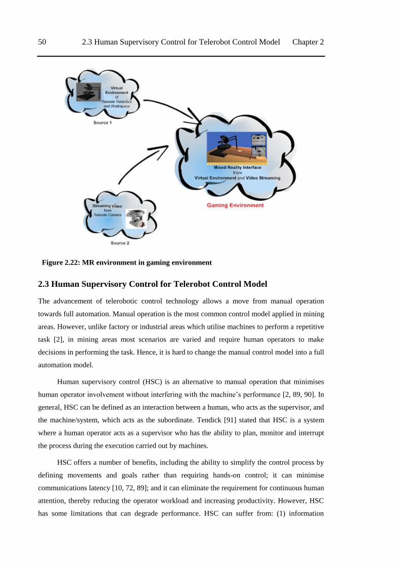
50 2.3 Human Supervisory Control for Telerobot Control Model Chapter 2
Figure 2.22: MR environment in gaming environment
2.3 Human Supervisory Control for Telerobot Control Model
The advancement of telerobotic control technology allows a move from manual operation
towards full automation. Manual operation is the most common control model applied in mining
areas. However, unlike factory or industrial areas which utilise machines to perform a repetitive
task [2], in mining areas most scenarios are varied and require human operators to make
decisions in performing the task. Hence, it is hard to change the manual control model into a full
automation model.
Human supervisory control (HSC) is an alternative to manual operation that minimises
human operator involvement without interfering with the machine‘s performance [2, 89, 90]. In
general, HSC can be defined as an interaction between a human, who acts as the supervisor, and
the machine/system, which acts as the subordinate. Tendick [91] stated that HSC is a system
where a human operator acts as a supervisor who has the ability to plan, monitor and interrupt
the process during the execution carried out by machines.
HSC offers a number of benefits, including the ability to simplify the control process by
defining movements and goals rather than requiring hands-on control; it can minimise
communications latency [10, 72, 89]; and it can eliminate the requirement for continuous human
attention, thereby reducing the operator workload and increasing productivity. However, HSC
has some limitations that can degrade performance. HSC can suffer from: (1) information
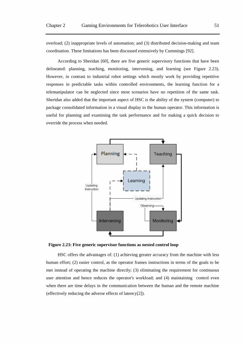
Chapter 2 Gaming Environments for Telerobotics User Interface 51
overload; (2) inappropriate levels of automation; and (3) distributed decision-making and team
coordination. These limitations has been discussed extensively by Cummings [92].
According to Sheridan [60], there are five generic supervisory functions that have been
delineated: planning, teaching, monitoring, intervening, and learning (see Figure 2.23).
However, in contrast to industrial robot settings which mostly work by providing repetitive
responses in predictable tasks within controlled environments, the learning function for a
telemanipulator can be neglected since most scenarios have no repetition of the same task.
Sheridan also added that the important aspect of HSC is the ability of the system (computer) to
package consolidated information in a visual display to the human operator. This information is
useful for planning and examining the task performance and for making a quick decision to
override the process when needed.
Figure 2.23: Five generic supervisor functions as nested control loop
HSC offers the advantages of: (1) achieving greater accuracy from the machine with less
human effort; (2) easier control, as the operator frames instructions in terms of the goals to be
met instead of operating the machine directly; (3) eliminating the requirement for continuous
user attention and hence reduces the operator's workload; and (4) maintaining control even
when there are time delays in the communication between the human and the remote machine
(effectively reducing the adverse effects of latency[2]).
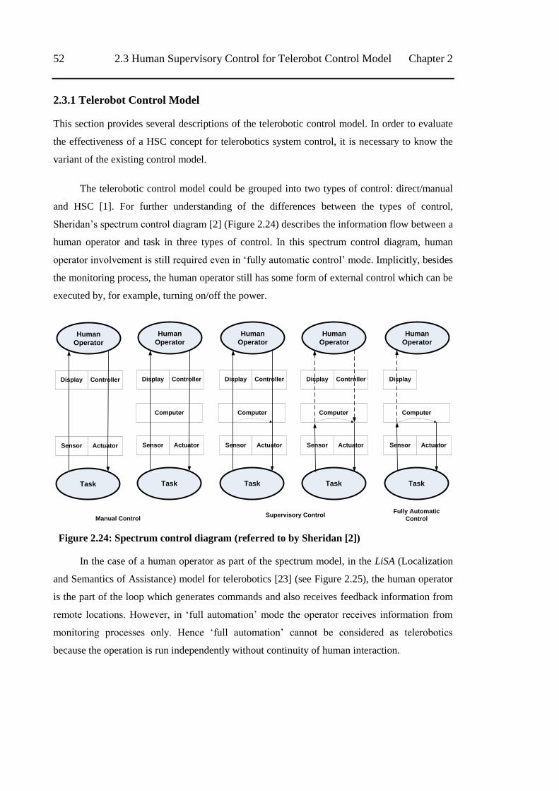
52 2.3 Human Supervisory Control for Telerobot Control Model Chapter 2
2.3.1 Telerobot Control Model
This section provides several descriptions of the telerobotic control model. In order to evaluate
the effectiveness of a HSC concept for telerobotics system control, it is necessary to know the
variant of the existing control model.
The telerobotic control model could be grouped into two types of control: direct/manual
and HSC [1]. For further understanding of the differences between the types of control,
Sheridan‘s spectrum control diagram [2] (Figure 2.24) describes the information flow between a
human operator and task in three types of control. In this spectrum control diagram, human
operator involvement is still required even in ‗fully automatic control‘ mode. Implicitly, besides
the monitoring process, the human operator still has some form of external control which can be
executed by, for example, turning on/off the power.
Human
Operator
Task
Sensor Actuator
Display Controller
Human
Operator
Task
Computer
Sensor Actuator
Display Controller
Human
Operator
Task
Computer
Sensor Actuator
Display Controller
Human
Operator
Task
Computer
Sensor Actuator
Display Controller
Human
Operator
Task
Computer
Sensor Actuator
Display
Manual ControlSupervisory Control
Fully Automatic
Control
Figure 2.24: Spectrum control diagram (referred to by Sheridan [2])
In the case of a human operator as part of the spectrum model, in the LiSA (Localization
and Semantics of Assistance) model for telerobotics [23] (see Figure 2.25), the human operator
is the part of the loop which generates commands and also receives feedback information from
remote locations. However, in ‗full automation‘ mode the operator receives information from
monitoring processes only. Hence ‗full automation‘ cannot be considered as telerobotics
because the operation is run independently without continuity of human interaction.
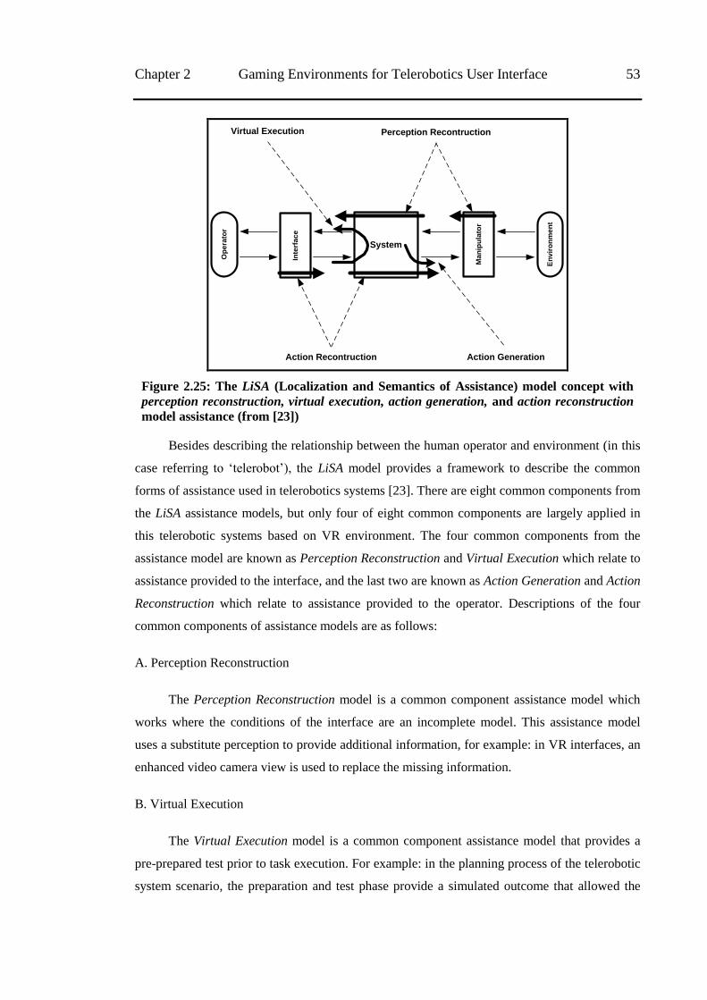
Chapter 2 Gaming Environments for Telerobotics User Interface 53
Op
era
tor
En
vir
on
me
nt
Inte
rfa
ce
Ma
nip
ula
tor
System
Virtual Execution Perception Recontruction
Action Recontruction Action Generation
Figure 2.25: The LiSA (Localization and Semantics of Assistance) model concept with
perception reconstruction, virtual execution, action generation, and action reconstruction
model assistance (from [23])
Besides describing the relationship between the human operator and environment (in this
case referring to ‗telerobot‘), the LiSA model provides a framework to describe the common
forms of assistance used in telerobotics systems [23]. There are eight common components from
the LiSA assistance models, but only four of eight common components are largely applied in
this telerobotic systems based on VR environment. The four common components from the
assistance model are known as Perception Reconstruction and Virtual Execution which relate to
assistance provided to the interface, and the last two are known as Action Generation and Action
Reconstruction which relate to assistance provided to the operator. Descriptions of the four
common components of assistance models are as follows:
A. Perception Reconstruction
The Perception Reconstruction model is a common component assistance model which
works where the conditions of the interface are an incomplete model. This assistance model
uses a substitute perception to provide additional information, for example: in VR interfaces, an
enhanced video camera view is used to replace the missing information.
B. Virtual Execution
The Virtual Execution model is a common component assistance model that provides a
pre-prepared test prior to task execution. For example: in the planning process of the telerobotic
system scenario, the preparation and test phase provide a simulated outcome that allowed the
54 2.3 Human Supervisory Control for Telerobot Control Model Chapter 2
operators to validate their instructions before they were transmitted to the robot. This form of
assistance is known as Virtual Execution.
C. Action Generation
This common component of assistance corresponds to Sheridan‘s [2] concept of
supervisory control. In an example of a telerobotics control scenario, the human operator is
allowed to specify the target positions. Then the system generates the required actions to move
the robot arm to that position without continual human input. This process of assistance is an
example of Action Generation.
D. Action Reconstruction
An example of this common component assistance model in telerobots control scenario is
the usage of a standard keyboard and mouse as input devices. Neither the mouse nor keyboard is
an anthropomorphic manipulator, thus preventing the operators from controlling the robot with
natural arm movements. However, a substitution action that utilises the mouse and keyboard can
be used to reconstruct the missing arm movement and this is known as Action Reconstruction.
Based on the description above, Action Reconstruction is also known as the opposite of
Perception Reconstruction.
As mentioned above, direct/manual control is still more common compared to
supervisory control. In direct/manual control, the operator guides the remote machine directly
using the hand-controller. This means that direct/manual control depends totally on real-time
human decision control. Meanwhile, in HSC, the remote machine relies on its own intelligence
to generate commands and perform the task without continual human involvement.
Related to the types of telerobotics, Fong et al [17] stated that the majority of research in
HSC has concentrated on telemanipulation rather than vehicle telerobotics. However, there are
many possibilities in the application of supervisory control in vehicle telerobotics. Recently,
HSC for vehicle telerobotics has been utilised with a variety of control modes (e.g. coordinated
control or individual actuator) and feedback (e.g. visual or haptic). Moreover, HSC is used to
address the problem of poor communication which is often found in vehicle telerobotics [17].
As mentioned in subsection 1.1.3, to identify the effectiveness and performance of my
telerobot application, I designed all the experiments using the common metrics developed by
Steinfeld et al. [24]. These metrics are grouped into two categories: system and operator
performance. In this manipulation scenario, the system's effectiveness can be identified by task
metrics, such as the percentage of navigation tasks successfully completed. The system
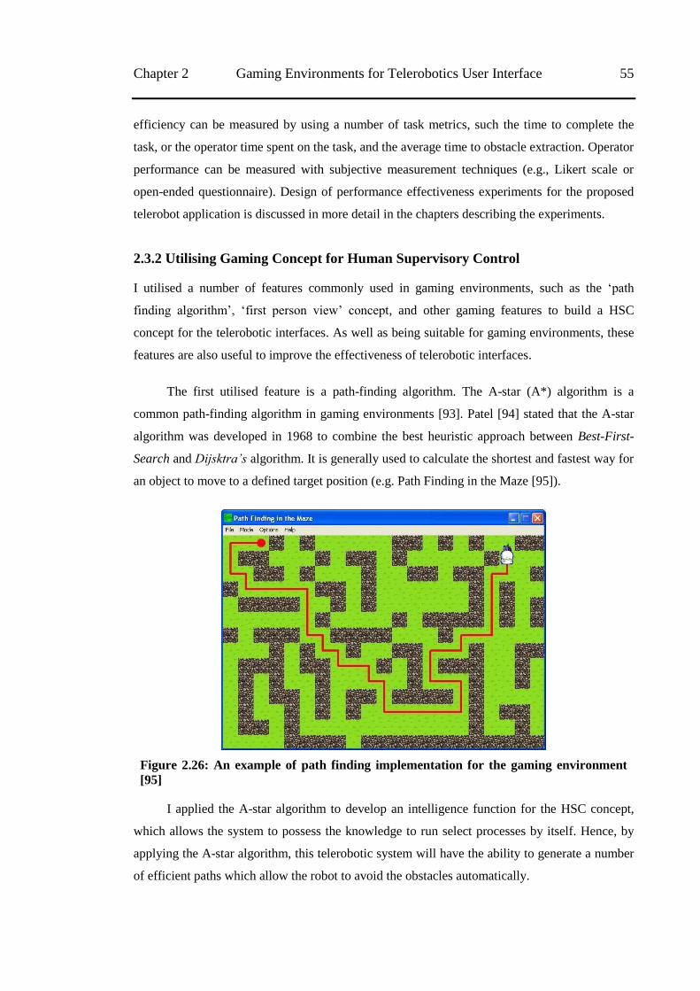
Chapter 2 Gaming Environments for Telerobotics User Interface 55
efficiency can be measured by using a number of task metrics, such the time to complete the
task, or the operator time spent on the task, and the average time to obstacle extraction. Operator
performance can be measured with subjective measurement techniques (e.g., Likert scale or
open-ended questionnaire). Design of performance effectiveness experiments for the proposed
telerobot application is discussed in more detail in the chapters describing the experiments.
2.3.2 Utilising Gaming Concept for Human Supervisory Control
I utilised a number of features commonly used in gaming environments, such as the ‗path
finding algorithm‘, ‗first person view‘ concept, and other gaming features to build a HSC
concept for the telerobotic interfaces. As well as being suitable for gaming environments, these
features are also useful to improve the effectiveness of telerobotic interfaces.
The first utilised feature is a path-finding algorithm. The A-star (A*) algorithm is a
common path-finding algorithm in gaming environments [93]. Patel [94] stated that the A-star
algorithm was developed in 1968 to combine the best heuristic approach between Best-First-
Search and Dijsktra’s algorithm. It is generally used to calculate the shortest and fastest way for
an object to move to a defined target position (e.g. Path Finding in the Maze [95]).
Figure 2.26: An example of path finding implementation for the gaming environment
[95]
I applied the A-star algorithm to develop an intelligence function for the HSC concept,
which allows the system to possess the knowledge to run select processes by itself. Hence, by
applying the A-star algorithm, this telerobotic system will have the ability to generate a number
of efficient paths which allow the robot to avoid the obstacles automatically.
56 2.3 Human Supervisory Control for Telerobot Control Model Chapter 2
Another feature is the ‗game viewpoint‘ on virtual camera. In a gaming environment,
virtual cameras play an important role in providing information about the VR environment.
Users can interact with the virtual object through the ‗remote-person view‘ or ‗first person view‘
as a basic viewpoint. Sko [96] mentioned that gamer/user performance when playing a game
can be improved by better viewpoint control. Hence, I suggest this feature also affects the
operator performance for this telerobotic interfaces.
For ‗input device‘ features, besides the gamepad (joystick), the mouse and keyboard are
the most common input devices for the gamer, especially for PC (personal computer) game
types. I argue the mouse device is also suitable to apply HSC in this telerobotic scenario. A
number of benefits of using a keyboard and mouse are: (1) commonly used and very compatible
for almost all PC applications, (2) cheaper compared to other input devices (e.g. haptic devices
and gamepad), (3) easy to use.
Another important feature in a gaming environment is the ability to provide some ‗extra
information‘. This feature is commonly used to provide additional information needed by
gamers (e.g. background and goals of the games). This feature can take the form of a virtual
object or text, which is very useful for gamers in completing their gaming tasks. In telerobotic
interfaces, providing extra information that is not available in a remote location can be very
useful for the operator (e.g. predictive display and visual feedback information). I consider that
both predictive displays and visual feedback information as useful in planning, monitoring and
performing the task. Besides, it could be argued that this predictive display concept can
minimise the effect of time delay to the operator [75].
All the gaming features above are used to build the MR and HSC concept for the
proposed telerobotic interfaces. These features can provide comfort in operating the telerobot
and improve the efficiency of user performance.
2.3.3 The Model of Response Movement based on Multi-Command Input
In contrast to direct/manual control of manipulators, telerobotics interaction based on HSC
allows human operators to plan the movement of the remote machine by entering a series of
commands as pre-defined positions. There are two possible kinds of response movements.
Firstly, the robot moves towards the newly defined position immediately; or, secondly, the robot
moves to achieve the queued series of positions one by one. I grouped the possible kinds of
response movements into two models, as follows.
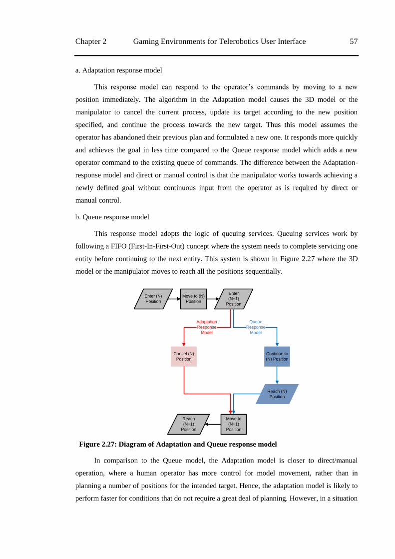
Chapter 2 Gaming Environments for Telerobotics User Interface 57
a. Adaptation response model
This response model can respond to the operator‘s commands by moving to a new
position immediately. The algorithm in the Adaptation model causes the 3D model or the
manipulator to cancel the current process, update its target according to the new position
specified, and continue the process towards the new target. Thus this model assumes the
operator has abandoned their previous plan and formulated a new one. It responds more quickly
and achieves the goal in less time compared to the Queue response model which adds a new
operator command to the existing queue of commands. The difference between the Adaptation-
response model and direct or manual control is that the manipulator works towards achieving a
newly defined goal without continuous input from the operator as is required by direct or
manual control.
b. Queue response model
This response model adopts the logic of queuing services. Queuing services work by
following a FIFO (First-In-First-Out) concept where the system needs to complete servicing one
entity before continuing to the next entity. This system is shown in Figure 2.27 where the 3D
model or the manipulator moves to reach all the positions sequentially.
Enter (N)
Position
Move to (N)
Position
Enter
(N+1)
Position
Cancel (N)
Position
Continue to
(N) Position
Reach (N)
Position
Move to
(N+1)
Position
Reach
(N+1)
Position
Queue
Response
Model
Adaptation
Response
Model
Figure 2.27: Diagram of Adaptation and Queue response model
In comparison to the Queue model, the Adaptation model is closer to direct/manual
operation, where a human operator has more control for model movement, rather than in
planning a number of positions for the intended target. Hence, the adaptation model is likely to
perform faster for conditions that do not require a great deal of planning. However, in a situation
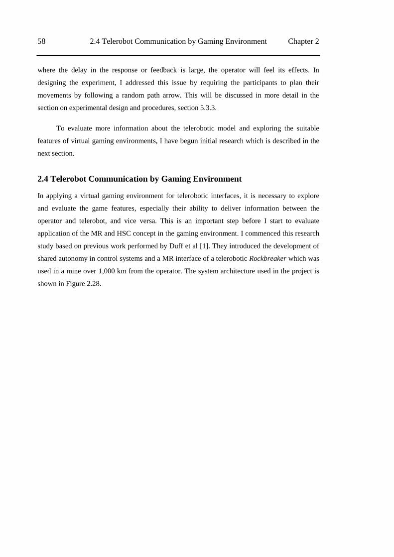
58 2.4 Telerobot Communication by Gaming Environment Chapter 2
where the delay in the response or feedback is large, the operator will feel its effects. In
designing the experiment, I addressed this issue by requiring the participants to plan their
movements by following a random path arrow. This will be discussed in more detail in the
section on experimental design and procedures, section 5.3.3.
To evaluate more information about the telerobotic model and exploring the suitable
features of virtual gaming environments, I have begun initial research which is described in the
next section.
2.4 Telerobot Communication by Gaming Environment
In applying a virtual gaming environment for telerobotic interfaces, it is necessary to explore
and evaluate the game features, especially their ability to deliver information between the
operator and telerobot, and vice versa. This is an important step before I start to evaluate
application of the MR and HSC concept in the gaming environment. I commenced this research
study based on previous work performed by Duff et al [1]. They introduced the development of
shared autonomy in control systems and a MR interface of a telerobotic Rockbreaker which was
used in a mine over 1,000 km from the operator. The system architecture used in the project is
shown in Figure 2.28.
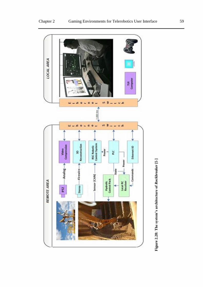
Chapter 2 Gaming Environments for Telerobotics User Interface 59
Fig
ure
2.2
8:
Th
e sy
stem
‟s a
rch
itec
ture
of
Rock
bre
aker
[5 ]
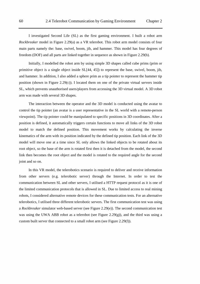
60 2.4 Telerobot Communication by Gaming Environment Chapter 2
I investigated Second Life (SL) as the first gaming environment. I built a robot arm
Rockbreaker model in Figure 2.29(a) as a VR telerobot. This robot arm model consists of four
main parts namely the: base, swivel, boom, jib, and hammer. This model has four degrees of
freedom (DOF) and all parts are linked together in sequence as shown in Figure 2.29(b).
Initially, I modelled the robot arm by using simple 3D shapes called cube prims (prim or
primitive object is a single object inside SL[44, 45]) to represent the base, swivel, boom, jib,
and hammer. In addition, I also added a sphere prim as a tip pointer to represent the hammer tip
position (shown in Figure 2.29(c)). I located them on one of the private virtual servers inside
SL, which prevents unauthorised users/players from accessing the 3D virtual model. A 3D robot
arm was made with several 3D shapes.
The interaction between the operator and the 3D model is conducted using the avatar to
control the tip pointer (an avatar is a user representative in the SL world with a remote-person
viewpoint). The tip pointer could be manipulated to specific positions in 3D coordinates. After a
position is defined, it automatically triggers certain functions to move all links of the 3D robot
model to match the defined position. This movement works by calculating the inverse
kinematics of the arm with its position indicated by the defined tip position. Each link of the 3D
model will move one at a time since SL only allows the linked objects to be rotated about its
root object, so the base of the arm is rotated first then it is detached from the model, the second
link then becomes the root object and the model is rotated to the required angle for the second
joint and so on.
In this VR model, the telerobotics scenario is required to deliver and receive information
from other servers (e.g. telerobotic server) through the Internet. In order to test the
communication between SL and other servers, I utilised a HTTP request protocol as it is one of
the limited communication protocols that is allowed in SL. Due to limited access to real mining
robots, I considered alternative remote devices for these communication tests. For an alternative
telerobotics, I utilised three different telerobotic servers. The first communication test was using
a Rockbreaker simulator web-based server (see Figure 2.29(e)). The second communication test
was using the UWA ABB robot as a telerobot (see Figure 2.29(g)), and the third was using a
custom built server that connected to a small robot arm (see Figure 2.29(f)).
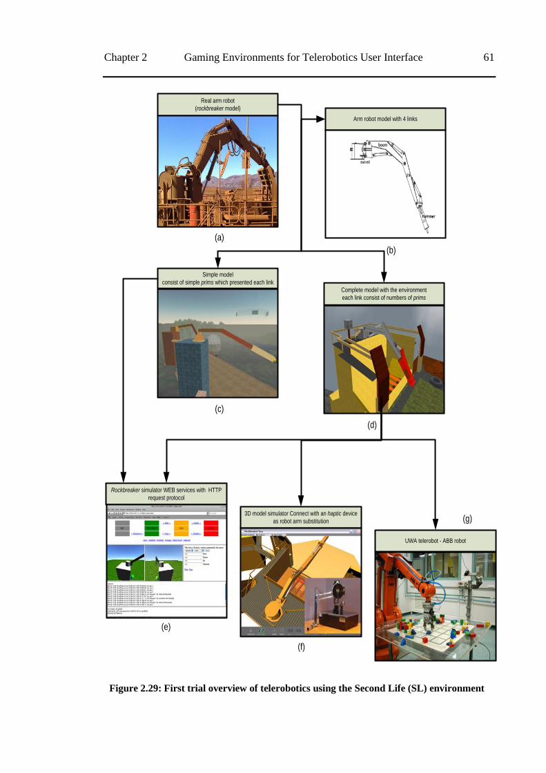
Chapter 2 Gaming Environments for Telerobotics User Interface 61
Real arm robot
(rockbreaker model)
Arm robot model with 4 links
Simple model
consist of simple prims which presented each link
Complete model with the environment
each link consist of numbers of prims
Rockbreaker simulator WEB services with HTTP
request protocol
UWA telerobot - ABB robot
3D model simulator Connect with an haptic device
as robot arm substitution
(a)
(b)
(c)
(d)
(e)
(f)
(g)
Figure 2.29: First trial overview of telerobotics using the Second Life (SL) environment
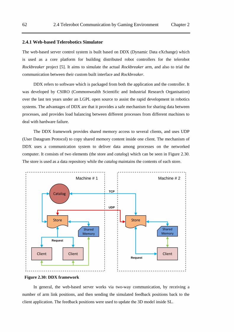
62 2.4 Telerobot Communication by Gaming Environment Chapter 2
2.4.1 Web-based Telerobotics Simulator
The web-based server control system is built based on DDX (Dynamic Data eXchange) which
is used as a core platform for building distributed robot controllers for the telerobot
Rockbreaker project [5]. It aims to simulate the actual Rockbreaker arm, and also to trial the
communication between their custom built interface and Rockbreaker.
DDX refers to software which is packaged from both the application and the controller. It
was developed by CSIRO (Commonwealth Scientific and Industrial Research Organisation)
over the last ten years under an LGPL open source to assist the rapid development in robotics
systems. The advantages of DDX are that it provides a safe mechanism for sharing data between
processes, and provides load balancing between different processes from different machines to
deal with hardware failure.
The DDX framework provides shared memory access to several clients, and uses UDP
(User Datagram Protocol) to copy shared memory content inside one client. The mechanism of
DDX uses a communication system to deliver data among processes on the networked
computer. It consists of two elements (the store and catalog) which can be seen in Figure 2.30.
The store is used as a data repository while the catalog maintains the contents of each store.
Store Store
Catalog
Shared Memory
Client
Shared Memory
Client Client
Machine # 1 Machine # 2
Request
Request
TCP
UDP
Figure 2.30: DDX framework
In general, the web-based server works via two-way communication, by receiving a
number of arm link positions, and then sending the simulated feedback positions back to the
client application. The feedback positions were used to update the 3D model inside SL.
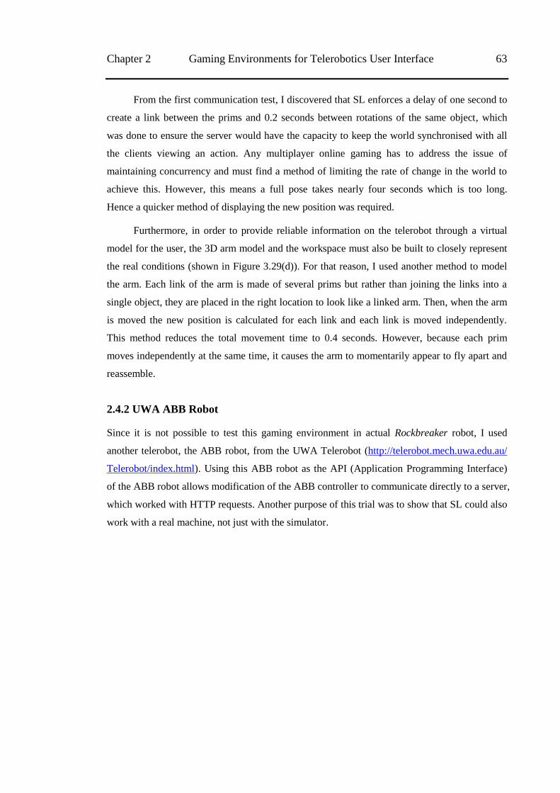
Chapter 2 Gaming Environments for Telerobotics User Interface 63
From the first communication test, I discovered that SL enforces a delay of one second to
create a link between the prims and 0.2 seconds between rotations of the same object, which
was done to ensure the server would have the capacity to keep the world synchronised with all
the clients viewing an action. Any multiplayer online gaming has to address the issue of
maintaining concurrency and must find a method of limiting the rate of change in the world to
achieve this. However, this means a full pose takes nearly four seconds which is too long.
Hence a quicker method of displaying the new position was required.
Furthermore, in order to provide reliable information on the telerobot through a virtual
model for the user, the 3D arm model and the workspace must also be built to closely represent
the real conditions (shown in Figure 3.29(d)). For that reason, I used another method to model
the arm. Each link of the arm is made of several prims but rather than joining the links into a
single object, they are placed in the right location to look like a linked arm. Then, when the arm
is moved the new position is calculated for each link and each link is moved independently.
This method reduces the total movement time to 0.4 seconds. However, because each prim
moves independently at the same time, it causes the arm to momentarily appear to fly apart and
reassemble.
2.4.2 UWA ABB Robot
Since it is not possible to test this gaming environment in actual Rockbreaker robot, I used
another telerobot, the ABB robot, from the UWA Telerobot (http://telerobot.mech.uwa.edu.au/
Telerobot/index.html). Using this ABB robot as the API (Application Programming Interface)
of the ABB robot allows modification of the ABB controller to communicate directly to a server,
which worked with HTTP requests. Another purpose of this trial was to show that SL could also
work with a real machine, not just with the simulator.
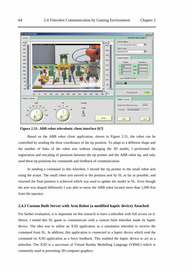
64 2.4 Telerobot Communication by Gaming Environment Chapter 2
Figure 2.31: ABB robot telerobotic client interface [67]
Based on the ABB robot client application, shown in Figure 2.31, the robot can be
controlled by sending the three coordinates of the tip position. To adapt to a different shape and
the number of links of the robot arm without changing the 3D model, I performed the
registration and rescaling of positions between the tip pointer and the ABB robot tip, and only
used these tip positions for commands and feedback of communication.
In sending a command to this telerobot, I moved the tip pointer to the small robot arm
using the avatar. The small robot arm moved to the position sent by SL as far as possible, and
returned the final position it achieved which was used to update the model in SL. Even though
the arm was shaped differently I was able to move the ABB robot located more than 1,000 Km
from the operator.
2.4.3 Custom Built Server with Arm Robot (a modified haptic device) Attached
For further evaluation, it is important on this research to have a telerobot with full access on it.
Hence, I tested this SL game to communicate with a custom built telerobot made by haptic
device. The idea was to utilise an X3D application as a simulation telerobot to receive the
command from SL. In addition, this application is connected to a haptic device which read the
command on X3D application as a force feedback. This enabled the haptic device to act as a
telerobot. The X3D is a successor of Virtual Reality Modelling Language (VRML) which is
commonly used in presenting 3D computer graphics.
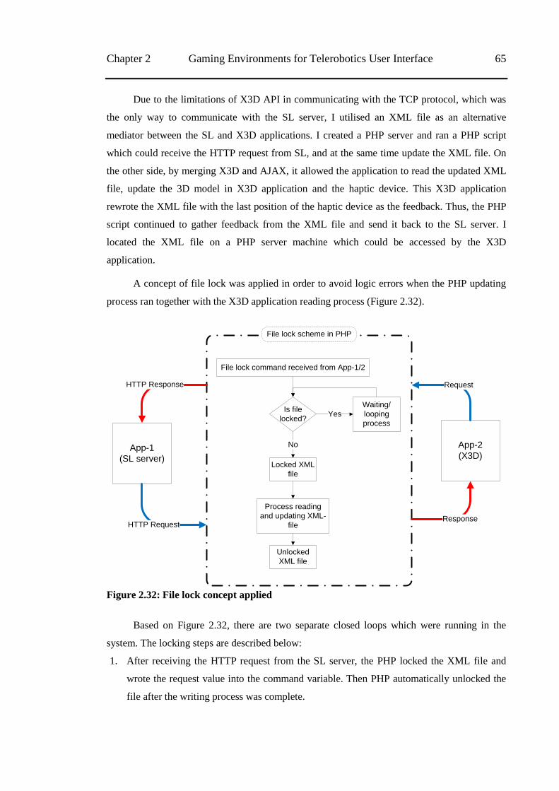
Chapter 2 Gaming Environments for Telerobotics User Interface 65
Due to the limitations of X3D API in communicating with the TCP protocol, which was
the only way to communicate with the SL server, I utilised an XML file as an alternative
mediator between the SL and X3D applications. I created a PHP server and ran a PHP script
which could receive the HTTP request from SL, and at the same time update the XML file. On
the other side, by merging X3D and AJAX, it allowed the application to read the updated XML
file, update the 3D model in X3D application and the haptic device. This X3D application
rewrote the XML file with the last position of the haptic device as the feedback. Thus, the PHP
script continued to gather feedback from the XML file and send it back to the SL server. I
located the XML file on a PHP server machine which could be accessed by the X3D
application.
A concept of file lock was applied in order to avoid logic errors when the PHP updating
process ran together with the X3D application reading process (Figure 2.32).
Is file
locked?
Locked XML
file
Process reading
and updating XML-
file
Unlocked
XML file
Waiting/
looping
process
No
Yes
App-1
(SL server)
App-2
(X3D)
HTTP Response
HTTP Request
Request
Response
File lock command received from App-1/2
File lock scheme in PHP
Figure 2.32: File lock concept applied
Based on Figure 2.32, there are two separate closed loops which were running in the
system. The locking steps are described below:
1. After receiving the HTTP request from the SL server, the PHP locked the XML file and
wrote the request value into the command variable. Then PHP automatically unlocked the
file after the writing process was complete.
66 2.4 Telerobot Communication by Gaming Environment Chapter 2
2. On the other side, while the PHP locked the file, the X3D application did a looping process
trying to access and read the XML file. When the file was unlocked, the X3D took over
and locked the file, then received the value of the command variable as the request position
to move the 3D model and the attached robot. The X3D application kept the XML file
locked until it wrote a feedback response into the response variable on the XML file.
3. Meanwhile, during the second step, the PHP continued to try to gain access to read the
response variable. When the file was unlocked, the PHP would automatically read the
response variable and send the HTTP response back to the SL.
During the communication test, besides the delay in getting feedback information from
the HTTP response, the applied file lock concept caused additional time delay in
communication. However, the remote simulation server and the robot successfully moved
following the request from the SL interface (with 0.3 – 0.5 seconds in a one-way
communication – for requests only). Moreover, the 3D model on SL succeeded in implementing
the feedback response from the telerobot. For example, when the telerobot gave a different
position from the request input because of particular condition, the 3D model would update the
position according to the last telerobot position.
Based on this preliminary test, SL has a number of limitations such as: (1) requires up to
two seconds in total for receiving the feedback and updating the telerobot model and (2) only
allows TCP/IP protocol to communicate with remote devices. However, this gaming
environment also provided satisfactory features to continue the research in evaluating the
effectiveness of MR interfaces and HSC for a telerobotic based on a gaming environment. To
explore the evaluation in more detail, the next chapter discusses the experiment of utilising MR
concept in a gaming environment.
67
Chapter 3
Evaluation of Gaming Environments with MR
Concept
This chapter discusses further exploration of the use of gaming engines as telerobotic interfaces.
A concept of mixed reality (MR) environment, which combines information from streaming
video and 3D computer visualisations inside the gaming environment, was evaluated as an
alternative to streaming video interfaces. This chapter discusses user performance from a
number of sub-experiments from two gaming engines and the feasibility of using the MR
concept in telerobotic interfaces. I demonstrate that the MR concept in a gaming engine can
provide an effective telerobotic interface.
3.1 Introduction
In this thesis, I explored the use of gaming environment technology for building telerobotic
interfaces. These have previously been viewed as different domains. In my initial stage of
research, as described in section 2.4 above, I showed that a virtual gaming environment (Second
Life - SL) has similarities features to telerobotic interfaces. According to Richer et al [33],
gaming environments have similarity to 3D graphics interfaces but also offer more features,
essentially a superset, compared to other 3D applications. They also mentioned that ―Unlike
most computer applications in which the interface serves as a means of interacting with some
underlying functionality, the sole purpose of a video game's interface is for the player to interact
with it‖. Hence, the gaming environment offers many similar features to telerobotic interfaces,
as well as its advantages in comparison to the existing computer 3D applications. Furthermore,
a number of existing telerobotic interfaces [1, 11, 21] have successfully used 3D graphics as an
alternative to video interfaces. This opens up the possibility of using a virtual-gaming
environment to build an interface, as it contains most of the technologies found in existing 3D
application interfaces. Besides providing a sophisticated environment for 3D modelling and the
freedom to define the actions and behaviour of the 3D model, a gaming environment offers
features, such as ease of integration with a variety of sensors and input devices, a wide range of
custom-built libraries and functions and an environment that is easy to use [33]. The multiuser
features in gaming environments can be used to share information and for collaborative-control
scenarios in future telerobotic system.
68 3.2 Prototype Implementation Chapter 3
Video feedback has been used for telerobotics since the 1950s, but streaming video on the
Internet only started to become popular at the end of the 1990s [2]. Initially, the main technical
limitations of streaming video were its requirement for high CPU load and Internet bandwidth
to support the required data transmission rates, especially if the TUI (Telerobotics User
Interfaces) was using more than one video stream [6]. With current devices available, the CPU
load is not an issue anymore. On the other hand, while high bandwidth is becoming more
readily available, it still has practical limitations. Other limitations include the restriction of
viewpoints in camera positions, difficulty in conveying non-visual information and the lack of
machine-readable information to support automation.
This chapter reports the experiment that was conducted to assess the effectiveness of the
MR concept on two gaming environments (Second Life and Simmersion‘s Mycosm) as
telerobotics user interfaces. Besides, the experiment also tried to assess the effect of the level of
user attention on the interface while performing the task. Before further description about the
experimental setting, the result and the discussion, the next section describes telerobotics
implementation which was used for the experiment.
3.2 Prototype Implementation
Based on the initial communication implementation on Chapter 2, and due to limited access to
real mining robots to test the proposed telerobotic interfaces, I built a smaller replica robot arm
as a telerobot. This robot has been built to replicate the Rockbreaker robot function
(manipulation robot arm).
I built the robot by modifying a haptic device. Despite this robot arm having a different
shape compared with the real Rockbreaker with three rather than four links, I added an engraver
as a hammer tip to this haptic device to transform this robot into a miniature Rockbreaker robot.
Figure 3.1 shows the modified shape of the telerobot model.
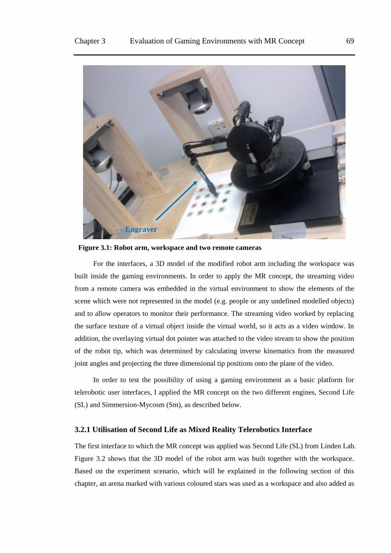
Chapter 3 Evaluation of Gaming Environments with MR Concept 69
Figure 3.1: Robot arm, workspace and two remote cameras
For the interfaces, a 3D model of the modified robot arm including the workspace was
built inside the gaming environments. In order to apply the MR concept, the streaming video
from a remote camera was embedded in the virtual environment to show the elements of the
scene which were not represented in the model (e.g. people or any undefined modelled objects)
and to allow operators to monitor their performance. The streaming video worked by replacing
the surface texture of a virtual object inside the virtual world, so it acts as a video window. In
addition, the overlaying virtual dot pointer was attached to the video stream to show the position
of the robot tip, which was determined by calculating inverse kinematics from the measured
joint angles and projecting the three dimensional tip positions onto the plane of the video.
In order to test the possibility of using a gaming environment as a basic platform for
telerobotic user interfaces, I applied the MR concept on the two different engines, Second Life
(SL) and Simmersion-Mycosm (Sm), as described below.
3.2.1 Utilisation of Second Life as Mixed Reality Telerobotics Interface
The first interface to which the MR concept was applied was Second Life (SL) from Linden Lab.
Figure 3.2 shows that the 3D model of the robot arm was built together with the workspace.
Based on the experiment scenario, which will be explained in the following section of this
chapter, an arena marked with various coloured stars was used as a workspace and also added as
Engraver
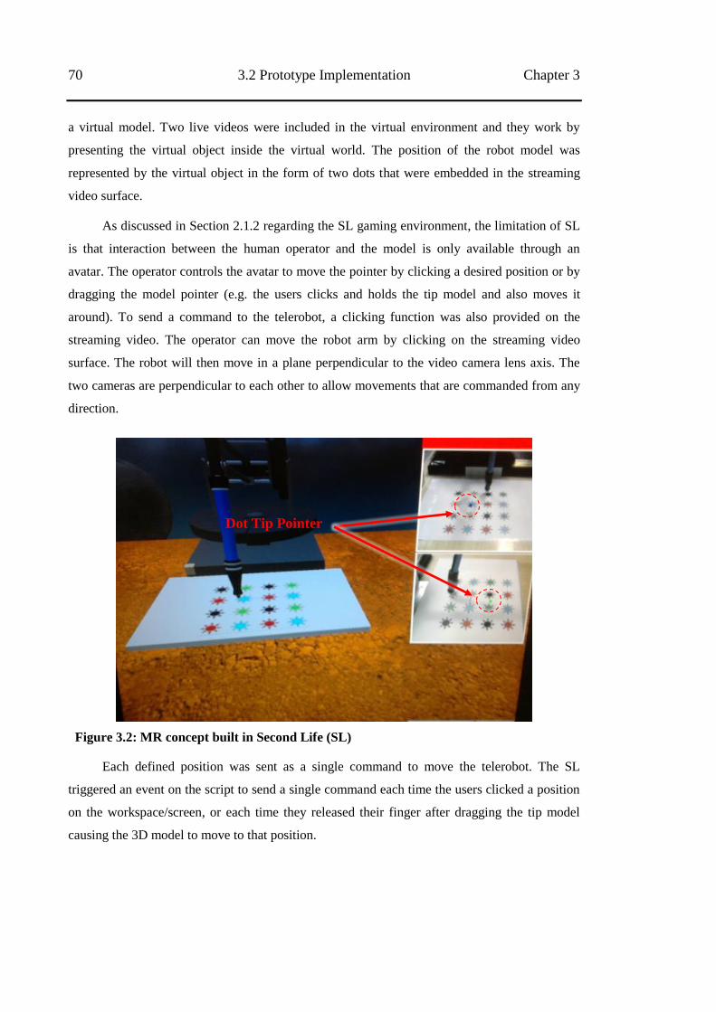
70 3.2 Prototype Implementation Chapter 3
a virtual model. Two live videos were included in the virtual environment and they work by
presenting the virtual object inside the virtual world. The position of the robot model was
represented by the virtual object in the form of two dots that were embedded in the streaming
video surface.
As discussed in Section 2.1.2 regarding the SL gaming environment, the limitation of SL
is that interaction between the human operator and the model is only available through an
avatar. The operator controls the avatar to move the pointer by clicking a desired position or by
dragging the model pointer (e.g. the users clicks and holds the tip model and also moves it
around). To send a command to the telerobot, a clicking function was also provided on the
streaming video. The operator can move the robot arm by clicking on the streaming video
surface. The robot will then move in a plane perpendicular to the video camera lens axis. The
two cameras are perpendicular to each other to allow movements that are commanded from any
direction.
Figure 3.2: MR concept built in Second Life (SL)
Each defined position was sent as a single command to move the telerobot. The SL
triggered an event on the script to send a single command each time the users clicked a position
on the workspace/screen, or each time they released their finger after dragging the tip model
causing the 3D model to move to that position.
Dot Tip Pointer
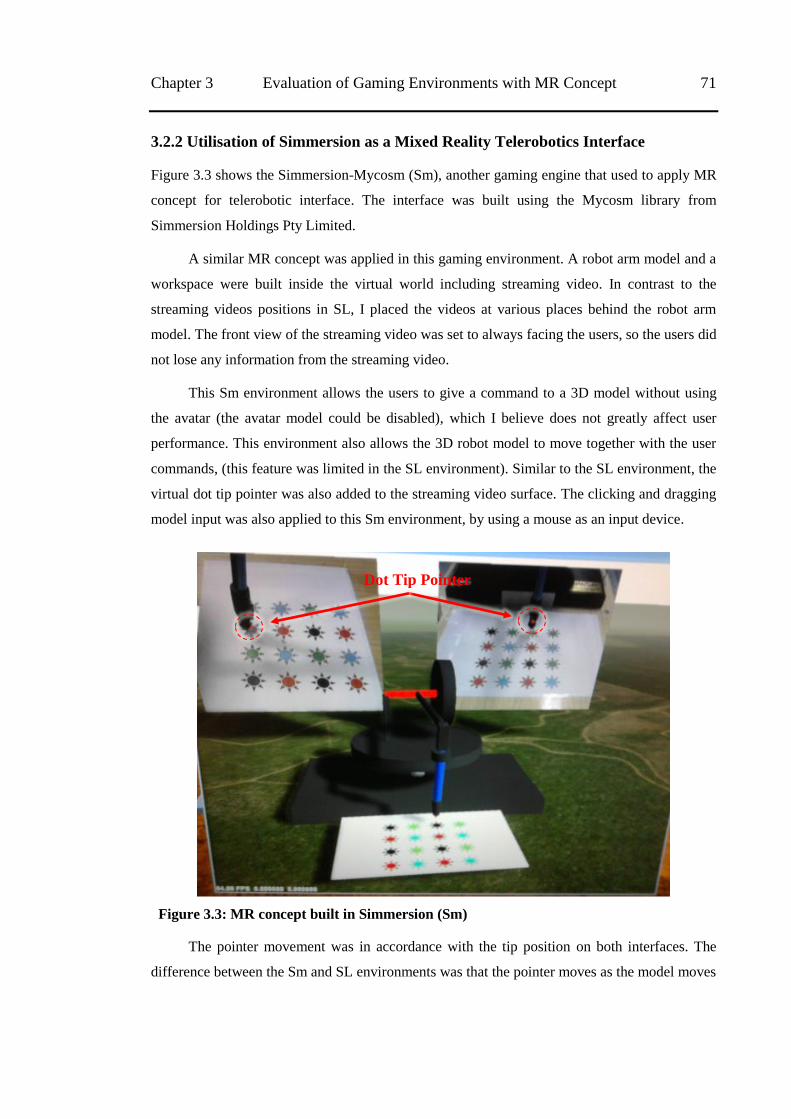
Chapter 3 Evaluation of Gaming Environments with MR Concept 71
3.2.2 Utilisation of Simmersion as a Mixed Reality Telerobotics Interface
Figure 3.3 shows the Simmersion-Mycosm (Sm), another gaming engine that used to apply MR
concept for telerobotic interface. The interface was built using the Mycosm library from
Simmersion Holdings Pty Limited.
A similar MR concept was applied in this gaming environment. A robot arm model and a
workspace were built inside the virtual world including streaming video. In contrast to the
streaming videos positions in SL, I placed the videos at various places behind the robot arm
model. The front view of the streaming video was set to always facing the users, so the users did
not lose any information from the streaming video.
This Sm environment allows the users to give a command to a 3D model without using
the avatar (the avatar model could be disabled), which I believe does not greatly affect user
performance. This environment also allows the 3D robot model to move together with the user
commands, (this feature was limited in the SL environment). Similar to the SL environment, the
virtual dot tip pointer was also added to the streaming video surface. The clicking and dragging
model input was also applied to this Sm environment, by using a mouse as an input device.
Figure 3.3: MR concept built in Simmersion (Sm)
The pointer movement was in accordance with the tip position on both interfaces. The
difference between the Sm and SL environments was that the pointer moves as the model moves
Dot Tip Pointer
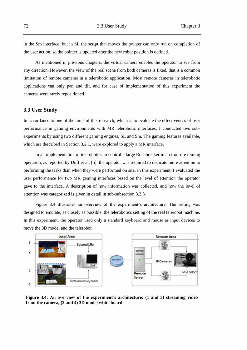
72 3.3 User Study Chapter 3
in the Sm interface, but in SL the script that moves the pointer can only run on completion of
the user action, so the pointer is updated after the new robot position is defined.
As mentioned in previous chapters, the virtual camera enables the operator to see from
any direction. However, the view of the real scene from both cameras is fixed, that is a common
limitation of remote cameras in a telerobotic application. Most remote cameras in telerobotic
applications can only pan and tilt, and for ease of implementation of this experiment the
cameras were rarely repositioned.
3.3 User Study
In accordance to one of the aims of this research, which is to evaluate the effectiveness of user
performance in gaming environments with MR telerobotic interfaces, I conducted two sub-
experiments by using two different gaming engines, SL and Sm. The gaming features available,
which are described in Section 3.2.1, were explored to apply a MR interface.
In an implementation of telerobotics to control a large Rockbreaker in an iron-ore mining
operation, as reported by Duff et al. [5], the operator was required to dedicate more attention to
performing the tasks than when they were performed on site. In this experiment, I evaluated the
user performance for two MR gaming interfaces based on the level of attention the operator
gave to the interface. A description of how information was collected, and how the level of
attention was categorized is given in detail in sub-subsection 3.3.3.
Figure 3.4 illustrates an overview of the experiment‘s architecture. The setting was
designed to emulate, as closely as possible, the telerobotics setting of the real telerobot machine.
In this experiment, the operator used only a standard keyboard and mouse as input devices to
move the 3D model and the telerobot.
Figure 3.4: An overview of the experiment‟s architecture: (1 and 3) streaming video
from the camera, (2 and 4) 3D model white board
Chapter 3 Evaluation of Gaming Environments with MR Concept 73
3.3.1 Apparatus
The two gaming environments with the MR interface applied were run on a desktop PC on the
client site, with the following specifications: NVIDIA Quadro FX 1700 for VGA and 2814 MB
in memory RAM. The display used a standard 19‖ monitor with a resolution of 1280 x 1024
pixels to run the interfaces.
In this experiment, a standard keyboard and optical mouse served as the user inputs to the
interfaces. Unlike the previous work, conducted by Duff et al. [5] and Hainsworth [6], which
used a gamepad, I chose the standard keyboard and optical mouse because they are suitable for
use with HSC for clicking and dragging. They are also ergonomic tools, familiar to users and
compatible with all computer gaming environments.
Based on a gaming control standard system, I set the four key arrows or ‗A‘,‘W‘,‘S‘,‘D‘
as left, up, down, and right respectively; and keys ‗E‘,‘C‘ or ‗Page up‘, ‗Page down‘ for zoom
in/zoom out to control the virtual camera viewpoint. By holding the ‗Alt‘ key together with a
‗left-click‘ of the mouse will allow the virtual camera to be repositioned. To control the robot
arm, ‗left clicking‘ the mouse will allow the robot tip to be moved forward, backward, right and
left; depressing the ‗Ctrl‘ key and ‗left clicking‘ the mouse will allow the mouse to control the
height of the tip.
The remote location consists of a robot arm with an engraver, which was used as a replica
Rockbreaker telerobot, and two Canon cameras of type VB-C50iR. One camera was placed 30
cm in front of the centre of the robot‘s workspace and 25 cm above the work surface. The other
camera was placed 10 cm to the right of the centre of the robot‘s workspace and 25 cm above
the work surface. Both cameras pointed to the centre of the scene.
I designed a remote workspace to conduct a simple task by using the robot arm to
push/move a target object from one position to another. Hence, a white board with 16 symbol
stars in four different colours (red, yellow, black, and green) were used as a position target
(shown in Figure 3.1), with these specifications, each symbol star of the same colour was placed
10 cm apart.
3.3.2 Participants
A total of 19 volunteers (12 males, seven females) participated in the experiment, all of whom
are students in various fields at the university. They range from 18 to 49 years of age (Mean
22.9, SD = 7.8). All participants were regular computer users with no previous experience in
this telerobotic scenario system. Nine of them played computer games ―often‖ (more than one
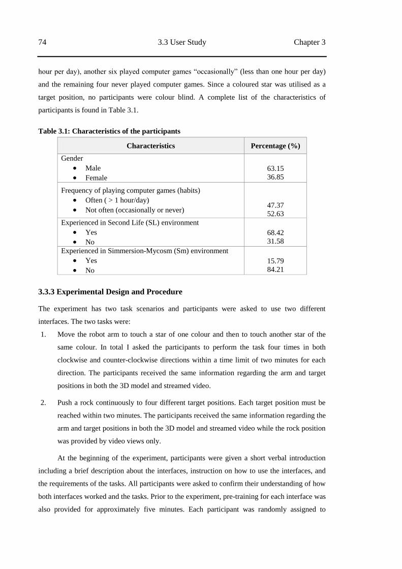
74 3.3 User Study Chapter 3
hour per day), another six played computer games ―occasionally‖ (less than one hour per day)
and the remaining four never played computer games. Since a coloured star was utilised as a
target position, no participants were colour blind. A complete list of the characteristics of
participants is found in Table 3.1.
Table 3.1: Characteristics of the participants
Characteristics Percentage (%)
Gender
Male
Female
63.15 36.85
Frequency of playing computer games (habits)
Often ( > 1 hour/day)
Not often (occasionally or never)
47.37 52.63
Experienced in Second Life (SL) environment
Yes
No
68.42 31.58
Experienced in Simmersion-Mycosm (Sm) environment
Yes
No
15.79 84.21
3.3.3 Experimental Design and Procedure
The experiment has two task scenarios and participants were asked to use two different
interfaces. The two tasks were:
1. Move the robot arm to touch a star of one colour and then to touch another star of the
same colour. In total I asked the participants to perform the task four times in both
clockwise and counter-clockwise directions within a time limit of two minutes for each
direction. The participants received the same information regarding the arm and target
positions in both the 3D model and streamed video.
2. Push a rock continuously to four different target positions. Each target position must be
reached within two minutes. The participants received the same information regarding the
arm and target positions in both the 3D model and streamed video while the rock position
was provided by video views only.
At the beginning of the experiment, participants were given a short verbal introduction
including a brief description about the interfaces, instruction on how to use the interfaces, and
the requirements of the tasks. All participants were asked to confirm their understanding of how
both interfaces worked and the tasks. Prior to the experiment, pre-training for each interface was
also provided for approximately five minutes. Each participant was randomly assigned to
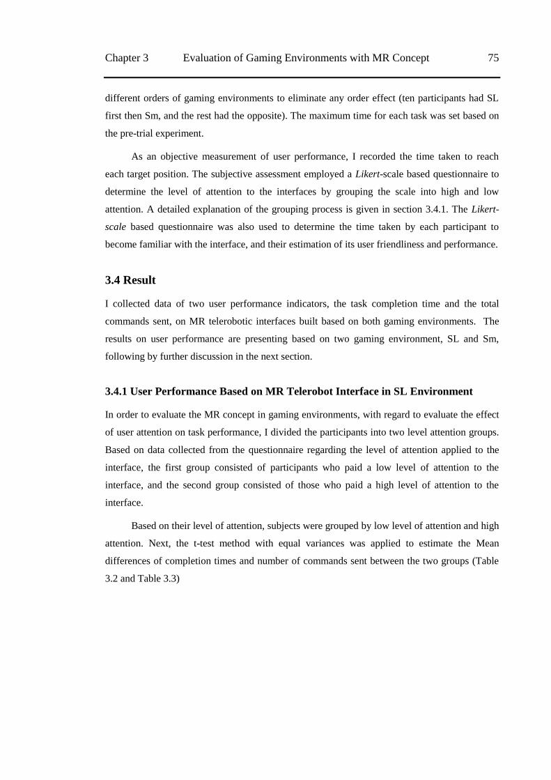
Chapter 3 Evaluation of Gaming Environments with MR Concept 75
different orders of gaming environments to eliminate any order effect (ten participants had SL
first then Sm, and the rest had the opposite). The maximum time for each task was set based on
the pre-trial experiment.
As an objective measurement of user performance, I recorded the time taken to reach
each target position. The subjective assessment employed a Likert-scale based questionnaire to
determine the level of attention to the interfaces by grouping the scale into high and low
attention. A detailed explanation of the grouping process is given in section 3.4.1. The Likert-
scale based questionnaire was also used to determine the time taken by each participant to
become familiar with the interface, and their estimation of its user friendliness and performance.
3.4 Result
I collected data of two user performance indicators, the task completion time and the total
commands sent, on MR telerobotic interfaces built based on both gaming environments. The
results on user performance are presenting based on two gaming environment, SL and Sm,
following by further discussion in the next section.
3.4.1 User Performance Based on MR Telerobot Interface in SL Environment
In order to evaluate the MR concept in gaming environments, with regard to evaluate the effect
of user attention on task performance, I divided the participants into two level attention groups.
Based on data collected from the questionnaire regarding the level of attention applied to the
interface, the first group consisted of participants who paid a low level of attention to the
interface, and the second group consisted of those who paid a high level of attention to the
interface.
Based on their level of attention, subjects were grouped by low level of attention and high
attention. Next, the t-test method with equal variances was applied to estimate the Mean
differences of completion times and number of commands sent between the two groups (Table
3.2 and Table 3.3)
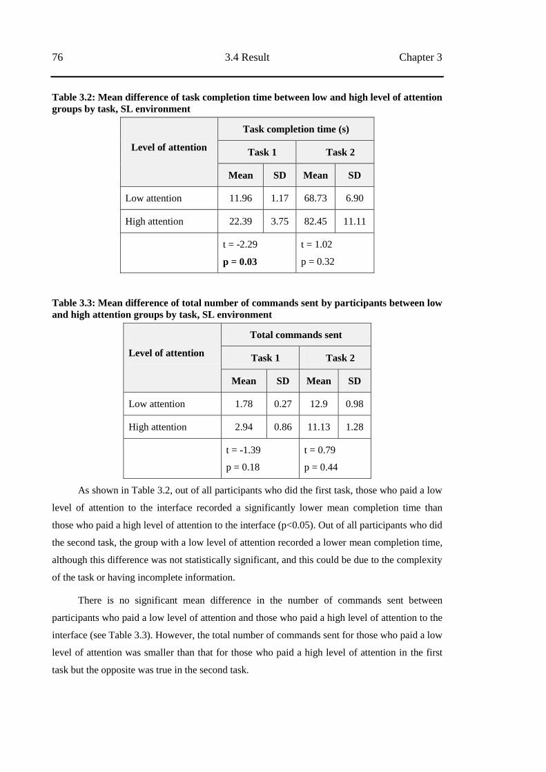
76 3.4 Result Chapter 3
Table 3.2: Mean difference of task completion time between low and high level of attention
groups by task, SL environment
Level of attention
Task completion time (s)
Task 1 Task 2
Mean SD Mean SD
Low attention 11.96 1.17 68.73 6.90
High attention 22.39 3.75 82.45 11.11
t = -2.29
p = 0.03
t = 1.02
p = 0.32
Table 3.3: Mean difference of total number of commands sent by participants between low
and high attention groups by task, SL environment
Level of attention
Total commands sent
Task 1 Task 2
Mean SD Mean SD
Low attention 1.78 0.27 12.9 0.98
High attention 2.94 0.86 11.13 1.28
t = -1.39
p = 0.18
t = 0.79
p = 0.44
As shown in Table 3.2, out of all participants who did the first task, those who paid a low
level of attention to the interface recorded a significantly lower mean completion time than
those who paid a high level of attention to the interface (p<0.05). Out of all participants who did
the second task, the group with a low level of attention recorded a lower mean completion time,
although this difference was not statistically significant, and this could be due to the complexity
of the task or having incomplete information.
There is no significant mean difference in the number of commands sent between
participants who paid a low level of attention and those who paid a high level of attention to the
interface (see Table 3.3). However, the total number of commands sent for those who paid a low
level of attention was smaller than that for those who paid a high level of attention in the first
task but the opposite was true in the second task.
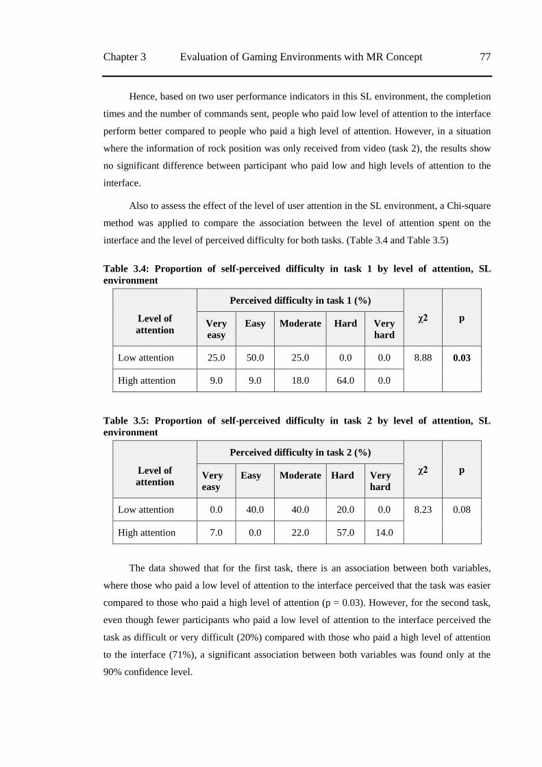
Chapter 3 Evaluation of Gaming Environments with MR Concept 77
Hence, based on two user performance indicators in this SL environment, the completion
times and the number of commands sent, people who paid low level of attention to the interface
perform better compared to people who paid a high level of attention. However, in a situation
where the information of rock position was only received from video (task 2), the results show
no significant difference between participant who paid low and high levels of attention to the
interface.
Also to assess the effect of the level of user attention in the SL environment, a Chi-square
method was applied to compare the association between the level of attention spent on the
interface and the level of perceived difficulty for both tasks. (Table 3.4 and Table 3.5)
Table 3.4: Proportion of self-perceived difficulty in task 1 by level of attention, SL
environment
Level of
attention
Perceived difficulty in task 1 (%)
χ2 p Very
easy Easy Moderate Hard Very
hard
Low attention 25.0 50.0 25.0 0.0 0.0 8.88 0.03
High attention 9.0 9.0 18.0 64.0 0.0
Table 3.5: Proportion of self-perceived difficulty in task 2 by level of attention, SL
environment
Level of
attention
Perceived difficulty in task 2 (%)
χ2 p Very
easy Easy Moderate Hard Very
hard
Low attention 0.0 40.0 40.0 20.0 0.0 8.23 0.08
High attention 7.0 0.0 22.0 57.0 14.0
The data showed that for the first task, there is an association between both variables,
where those who paid a low level of attention to the interface perceived that the task was easier
compared to those who paid a high level of attention (p = 0.03). However, for the second task,
even though fewer participants who paid a low level of attention to the interface perceived the
task as difficult or very difficult (20%) compared with those who paid a high level of attention
to the interface (71%), a significant association between both variables was found only at the
90% confidence level.
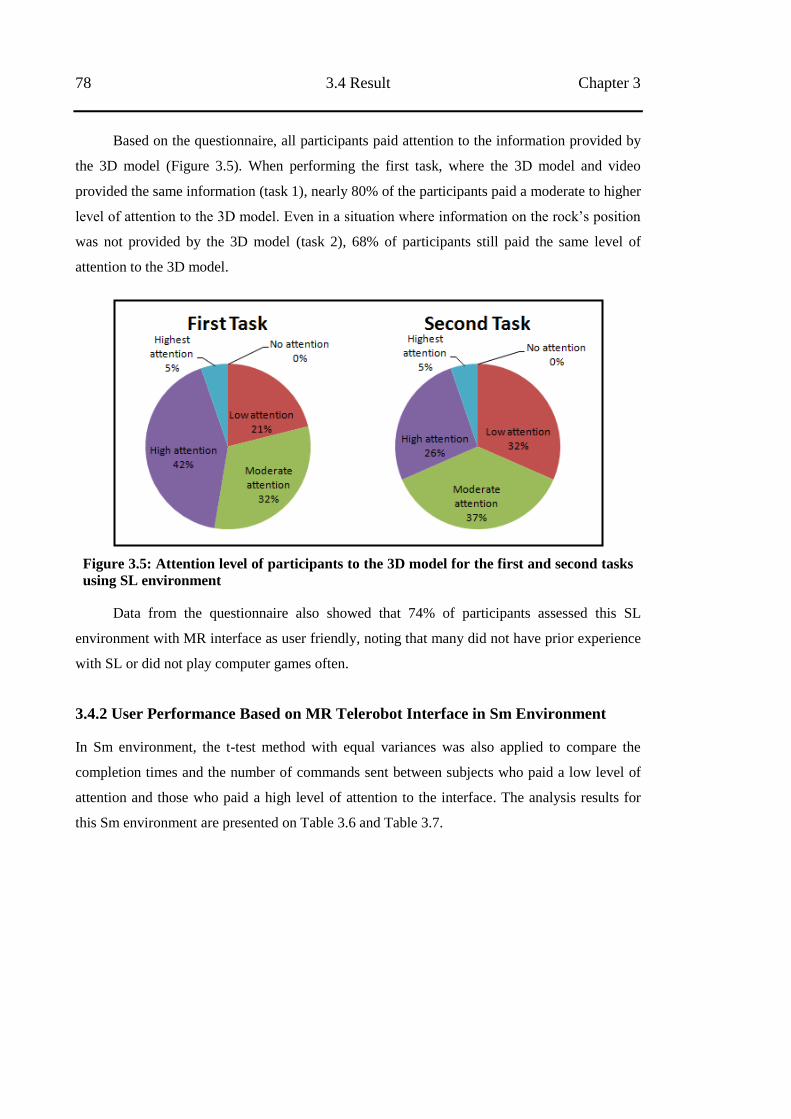
78 3.4 Result Chapter 3
Based on the questionnaire, all participants paid attention to the information provided by
the 3D model (Figure 3.5). When performing the first task, where the 3D model and video
provided the same information (task 1), nearly 80% of the participants paid a moderate to higher
level of attention to the 3D model. Even in a situation where information on the rock‘s position
was not provided by the 3D model (task 2), 68% of participants still paid the same level of
attention to the 3D model.
Figure 3.5: Attention level of participants to the 3D model for the first and second tasks
using SL environment
Data from the questionnaire also showed that 74% of participants assessed this SL
environment with MR interface as user friendly, noting that many did not have prior experience
with SL or did not play computer games often.
3.4.2 User Performance Based on MR Telerobot Interface in Sm Environment
In Sm environment, the t-test method with equal variances was also applied to compare the
completion times and the number of commands sent between subjects who paid a low level of
attention and those who paid a high level of attention to the interface. The analysis results for
this Sm environment are presented on Table 3.6 and Table 3.7.
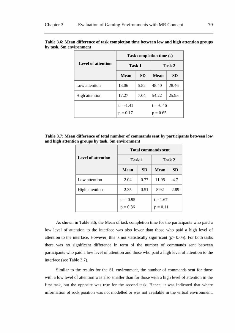
Chapter 3 Evaluation of Gaming Environments with MR Concept 79
Table 3.6: Mean difference of task completion time between low and high attention groups
by task, Sm environment
Level of attention
Task completion time (s)
Task 1 Task 2
Mean SD Mean SD
Low attention 13.06 5.82 48.40 28.46
High attention 17.27 7.04 54.22 25.95
t = -1.41
p = 0.17
t = -0.46
p = 0.65
Table 3.7: Mean difference of total number of commands sent by participants between low
and high attention groups by task, Sm environment
Level of attention
Total commands sent
Task 1 Task 2
Mean SD Mean SD
Low attention 2.04 0.77 11.95 4.7
High attention 2.35 0.51 8.92 2.89
t = -0.95
p = 0.36
t = 1.67
p = 0.11
As shown in Table 3.6, the Mean of task completion time for the participants who paid a
low level of attention to the interface was also lower than those who paid a high level of
attention to the interface. However, this is not statistically significant (p> 0.05). For both tasks
there was no significant difference in term of the number of commands sent between
participants who paid a low level of attention and those who paid a high level of attention to the
interface (see Table 3.7).
Similar to the results for the SL environment, the number of commands sent for those
with a low level of attention was also smaller than for those with a high level of attention in the
first task, but the opposite was true for the second task. Hence, it was indicated that where
information of rock position was not modelled or was not available in the virtual environment,
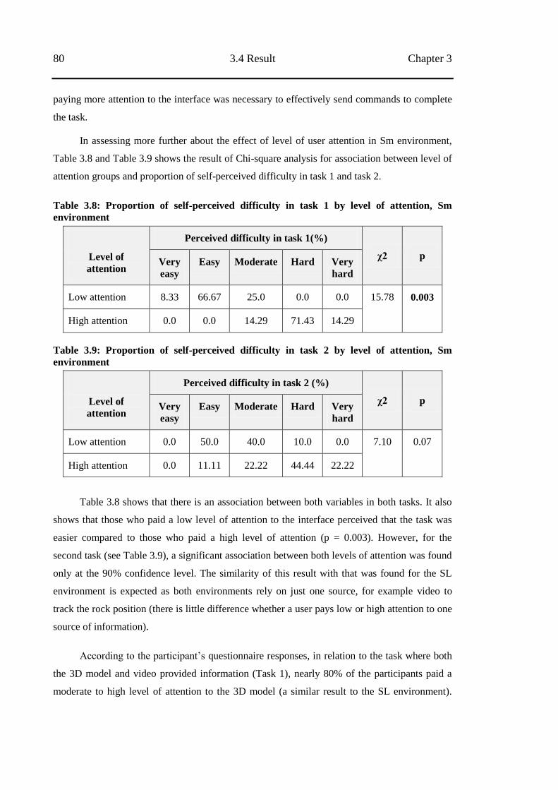
80 3.4 Result Chapter 3
paying more attention to the interface was necessary to effectively send commands to complete
the task.
In assessing more further about the effect of level of user attention in Sm environment,
Table 3.8 and Table 3.9 shows the result of Chi-square analysis for association between level of
attention groups and proportion of self-perceived difficulty in task 1 and task 2.
Table 3.8: Proportion of self-perceived difficulty in task 1 by level of attention, Sm
environment
Level of
attention
Perceived difficulty in task 1(%)
χ2 p Very
easy Easy Moderate Hard Very
hard
Low attention 8.33 66.67 25.0 0.0 0.0 15.78 0.003
High attention 0.0 0.0 14.29 71.43 14.29
Table 3.9: Proportion of self-perceived difficulty in task 2 by level of attention, Sm
environment
Level of
attention
Perceived difficulty in task 2 (%)
χ2 p Very
easy Easy Moderate Hard Very
hard
Low attention 0.0 50.0 40.0 10.0 0.0 7.10 0.07
High attention 0.0 11.11 22.22 44.44 22.22
Table 3.8 shows that there is an association between both variables in both tasks. It also
shows that those who paid a low level of attention to the interface perceived that the task was
easier compared to those who paid a high level of attention (p = 0.003). However, for the
second task (see Table 3.9), a significant association between both levels of attention was found
only at the 90% confidence level. The similarity of this result with that was found for the SL
environment is expected as both environments rely on just one source, for example video to
track the rock position (there is little difference whether a user pays low or high attention to one
source of information).
According to the participant‘s questionnaire responses, in relation to the task where both
the 3D model and video provided information (Task 1), nearly 80% of the participants paid a
moderate to high level of attention to the 3D model (a similar result to the SL environment).
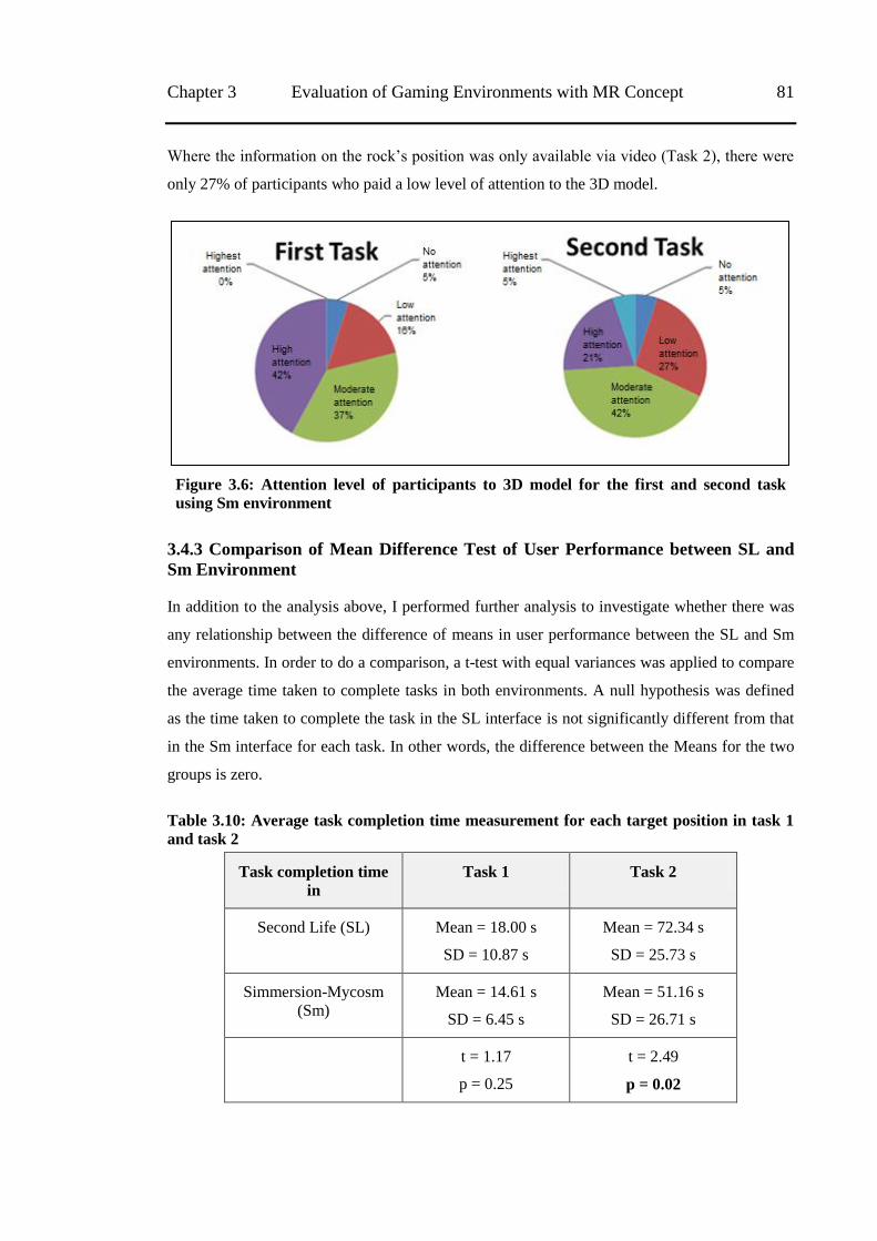
Chapter 3 Evaluation of Gaming Environments with MR Concept 81
Where the information on the rock‘s position was only available via video (Task 2), there were
only 27% of participants who paid a low level of attention to the 3D model.
Figure 3.6: Attention level of participants to 3D model for the first and second task
using Sm environment
3.4.3 Comparison of Mean Difference Test of User Performance between SL and
Sm Environment
In addition to the analysis above, I performed further analysis to investigate whether there was
any relationship between the difference of means in user performance between the SL and Sm
environments. In order to do a comparison, a t-test with equal variances was applied to compare
the average time taken to complete tasks in both environments. A null hypothesis was defined
as the time taken to complete the task in the SL interface is not significantly different from that
in the Sm interface for each task. In other words, the difference between the Means for the two
groups is zero.
Table 3.10: Average task completion time measurement for each target position in task 1
and task 2
Task completion time
in Task 1 Task 2
Second Life (SL) Mean = 18.00 s
SD = 10.87 s
Mean = 72.34 s
SD = 25.73 s
Simmersion-Mycosm
(Sm) Mean = 14.61 s
SD = 6.45 s
Mean = 51.16 s
SD = 26.71 s
t = 1.17
p = 0.25
t = 2.49
p = 0.02
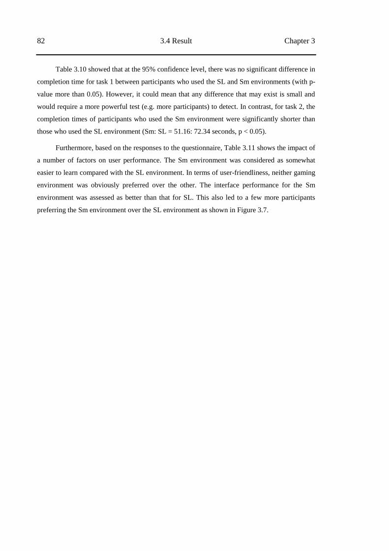
82 3.4 Result Chapter 3
Table 3.10 showed that at the 95% confidence level, there was no significant difference in
completion time for task 1 between participants who used the SL and Sm environments (with p-
value more than 0.05). However, it could mean that any difference that may exist is small and
would require a more powerful test (e.g. more participants) to detect. In contrast, for task 2, the
completion times of participants who used the Sm environment were significantly shorter than
those who used the SL environment (Sm: SL = 51.16: 72.34 seconds, p < 0.05).
Furthermore, based on the responses to the questionnaire, Table 3.11 shows the impact of
a number of factors on user performance. The Sm environment was considered as somewhat
easier to learn compared with the SL environment. In terms of user-friendliness, neither gaming
environment was obviously preferred over the other. The interface performance for the Sm
environment was assessed as better than that for SL. This also led to a few more participants
preferring the Sm environment over the SL environment as shown in Figure 3.7.
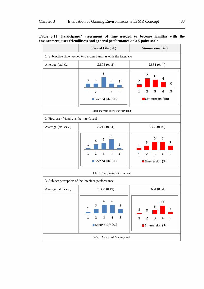
Chapter 3 Evaluation of Gaming Environments with MR Concept 83
Table 3.11: Participants‟ assessment of time needed to become familiar with the
environment, user friendliness and general performance on a 5 point scale
Second Life (SL) Simmersion (Sm)
1. Subjective time needed to become familiar with the interface
Average (std. d.) 2.895 (0.42) 2.831 (0.44)
Info: 1 very short, 5 very long
2. How user friendly is the interfaces?
Average (std. dev.) 3.211 (0.64) 3.368 (0.49)
Info: 1 very easy, 5 very hard
3. Subject perception of the interface performance
Average (std. dev.) 3.368 (0.49) 3.684 (0.94)
Info: 1 very bad, 5 very well
3 3
8
3 2
1 2 3 4 5
Second Life (SL)
2
7 6 4
0
1 2 3 4 5
Simmersion (Sm)
1 4 5
8
1
1 2 3 4 5
Second Life (SL)
1 3
6 6 3
1 2 3 4 5
Simmersion (Sm)
1 3
6 6 3
1 2 3 4 5
Second Life (SL)
1 0 5
11
2
1 2 3 4 5
Simmersion (Sm)
84 3.4 Result Chapter 3
Figure 3.7: Preferred environment based on questionnaire
Based on spoken and written comments, a number of participants mentioned that they
experienced difficulty in performing the task when the virtual camera viewpoint was very
different from that of the actual camera. Several participants commented that when specifying a
location using the video overlay they found it difficult to place the robot tip where they intended
in relation to the rock. However, when the operator manipulated the 3D model in the virtual
world while at the same time observing the video through the tip pointer overlay, they were able
to place the robot where they intended. In addition, given the higher productivity observed in
task 2, it was surprising that only 11% more participants preferred the Sm interface over the SL
interface.
3.4.4 Dragging versus Clicking
As mentioned in the prototype implementation section in this chapter, MR telerobotic interfaces
allowed the participant to give a command using two methods, clicking and dragging. Based on
my observations of user behaviour during the experiment, most participants tried both clicking
and dragging when giving commands to push the rock from one position to another. However,
participants tended to use the clicking method around three times more than they used the
dragging method, in terms of the average of proportion of total use (clicking: dragging =
72.03%: 27.97%, with SD = 12.49%).
I did not conduct further analysis to test the effects of both methods on user performance,
as the experiment was not designed to test these relationships. However, based on the number of
commands sent for each method, I was able to determine that clicking was the favourite method.
Chapter 3 Evaluation of Gaming Environments with MR Concept 85
I had already assumed the clicking method was preferable to the dragging method since it
required less effort in defining the robot‘s target position.
3.5 Discussion
The experiment was conducted to evaluate the effectiveness of the MR concept on two gaming
environments as part of the aims of thesis to develop an application prototype for telerobotics in
remote mining equipment scenarios by utilising the features of gaming environments. Here, I
determined task completion time, total commands sent and perceived level of difficulty as the
outcome variables to indicate the user performance, with level of attention defined as a predictor
variable. Analysis was conducted to compare outcome variables between the two groups
categorized based on the predictor variable as well as between the interface, Sm and SL.
The results analysis on user performance in subsections 3.4.1 and 3.4.2 shows that paying
a low level of attention to the interface and still being able to perform the task well suggests the
participant was immersed in the interface and received a sufficient flow of information. This is
supported by an argument by Chikszentmihalyi et al. [97], which defined immersion as a state
of concentration so focused as to cause an absolute absorption in an activity. The user-
friendliness of the interface and the enjoyment gained by the operator when interacting with the
interface created a sufficiently immersive experience for the operator to perform the task well.
In task 1 where all required information is provided from both sources of information (3D
model and video views), the experiment showed a statistically significant shorter task
completion time and a lower perceived difficulty level for participants who paid a low level of
attention to the interface. Since in task 1 ensuring that all the information needed to complete
the task was sufficiently well modelled in the virtual world and available without referring to
the video, the task could be undertaken by only paying attention to the video or to the model.
My observations suggest that only occasional reference was made to the video which is in
contrast to the real Rockbreaker interface [5] where the operator‘s attention was predominantly
directed at the video and the model was mostly unused. This is in line with Adams [98] that
mentioned the gaming environment is able to simulate reality inside the user‘s mind.
In contrast, in the task 2 where information about the rock position was only provided
from the video views and not in the 3D model, which is usually the case in most telerobotics
scenarios, the experiment did not demonstrate any association between the above variables. This
might be due to an inadequate number of participants or other aspects of the gaming [98]. Based
on this result, I suggest that other than being an immersive environment, a good interface should
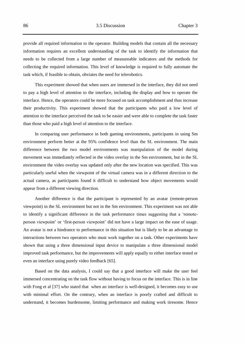
86 3.5 Discussion Chapter 3
provide all required information to the operator. Building models that contain all the necessary
information requires an excellent understanding of the task to identify the information that
needs to be collected from a large number of measureable indicators and the methods for
collecting the required information. This level of knowledge is required to fully automate the
task which, if feasible to obtain, obviates the need for telerobotics.
This experiment showed that when users are immersed in the interface, they did not need
to pay a high level of attention to the interface, including the display and how to operate the
interface. Hence, the operators could be more focused on task accomplishment and thus increase
their productivity. This experiment showed that the participants who paid a low level of
attention to the interface perceived the task to be easier and were able to complete the task faster
than those who paid a high level of attention to the interface.
In comparing user performance in both gaming environments, participants in using Sm
environment perform better at the 95% confidence level than the SL environment. The main
difference between the two model environments was manipulation of the model during
movement was immediately reflected in the video overlay in the Sm environment, but in the SL
environment the video overlay was updated only after the new location was specified. This was
particularly useful when the viewpoint of the virtual camera was in a different direction to the
actual camera, as participants found it difficult to understand how object movements would
appear from a different viewing direction.
Another difference is that the participant is represented by an avatar (remote-person
viewpoint) in the SL environment but not in the Sm environment. This experiment was not able
to identify a significant difference in the task performance times suggesting that a ‗remote-
person viewpoint‘ or ‗first-person viewpoint‘ did not have a large impact on the ease of usage.
An avatar is not a hindrance to performance in this situation but is likely to be an advantage to
interactions between two operators who must work together on a task. Other experiments have
shown that using a three dimensional input device to manipulate a three dimensional model
improved task performance, but the improvements will apply equally to either interface tested or
even an interface using purely video feedback [65].
Based on the data analysis, I could say that a good interface will make the user feel
immersed concentrating on the task flow without having to focus on the interface. This is in line
with Fong et al [37] who stated that when an interface is well-designed, it becomes easy to use
with minimal effort. On the contrary, when an interface is poorly crafted and difficult to
understand, it becomes burdensome, limiting performance and making work tiresome. Hence
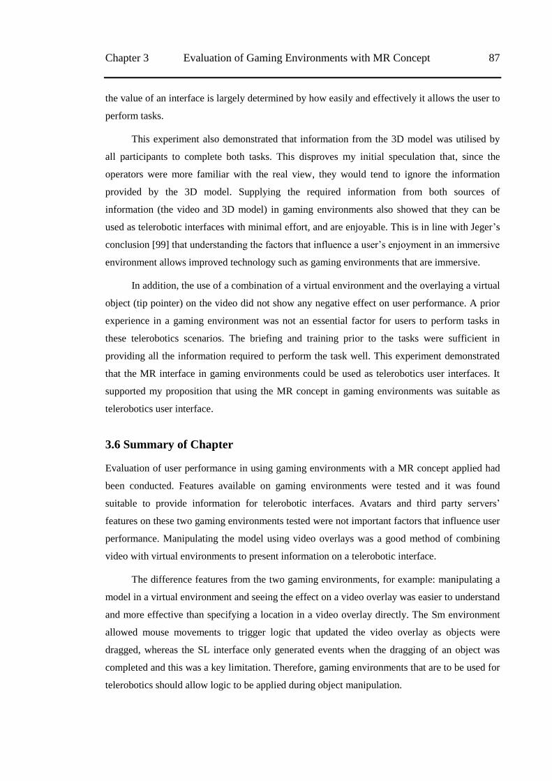
Chapter 3 Evaluation of Gaming Environments with MR Concept 87
the value of an interface is largely determined by how easily and effectively it allows the user to
perform tasks.
This experiment also demonstrated that information from the 3D model was utilised by
all participants to complete both tasks. This disproves my initial speculation that, since the
operators were more familiar with the real view, they would tend to ignore the information
provided by the 3D model. Supplying the required information from both sources of
information (the video and 3D model) in gaming environments also showed that they can be
used as telerobotic interfaces with minimal effort, and are enjoyable. This is in line with Jeger‘s
conclusion [99] that understanding the factors that influence a user‘s enjoyment in an immersive
environment allows improved technology such as gaming environments that are immersive.
In addition, the use of a combination of a virtual environment and the overlaying a virtual
object (tip pointer) on the video did not show any negative effect on user performance. A prior
experience in a gaming environment was not an essential factor for users to perform tasks in
these telerobotics scenarios. The briefing and training prior to the tasks were sufficient in
providing all the information required to perform the task well. This experiment demonstrated
that the MR interface in gaming environments could be used as telerobotics user interfaces. It
supported my proposition that using the MR concept in gaming environments was suitable as
telerobotics user interface.
3.6 Summary of Chapter
Evaluation of user performance in using gaming environments with a MR concept applied had
been conducted. Features available on gaming environments were tested and it was found
suitable to provide information for telerobotic interfaces. Avatars and third party servers‘
features on these two gaming environments tested were not important factors that influence user
performance. Manipulating the model using video overlays was a good method of combining
video with virtual environments to present information on a telerobotic interface.
The difference features from the two gaming environments, for example: manipulating a
model in a virtual environment and seeing the effect on a video overlay was easier to understand
and more effective than specifying a location in a video overlay directly. The Sm environment
allowed mouse movements to trigger logic that updated the video overlay as objects were
dragged, whereas the SL interface only generated events when the dragging of an object was
completed and this was a key limitation. Therefore, gaming environments that are to be used for
telerobotics should allow logic to be applied during object manipulation.
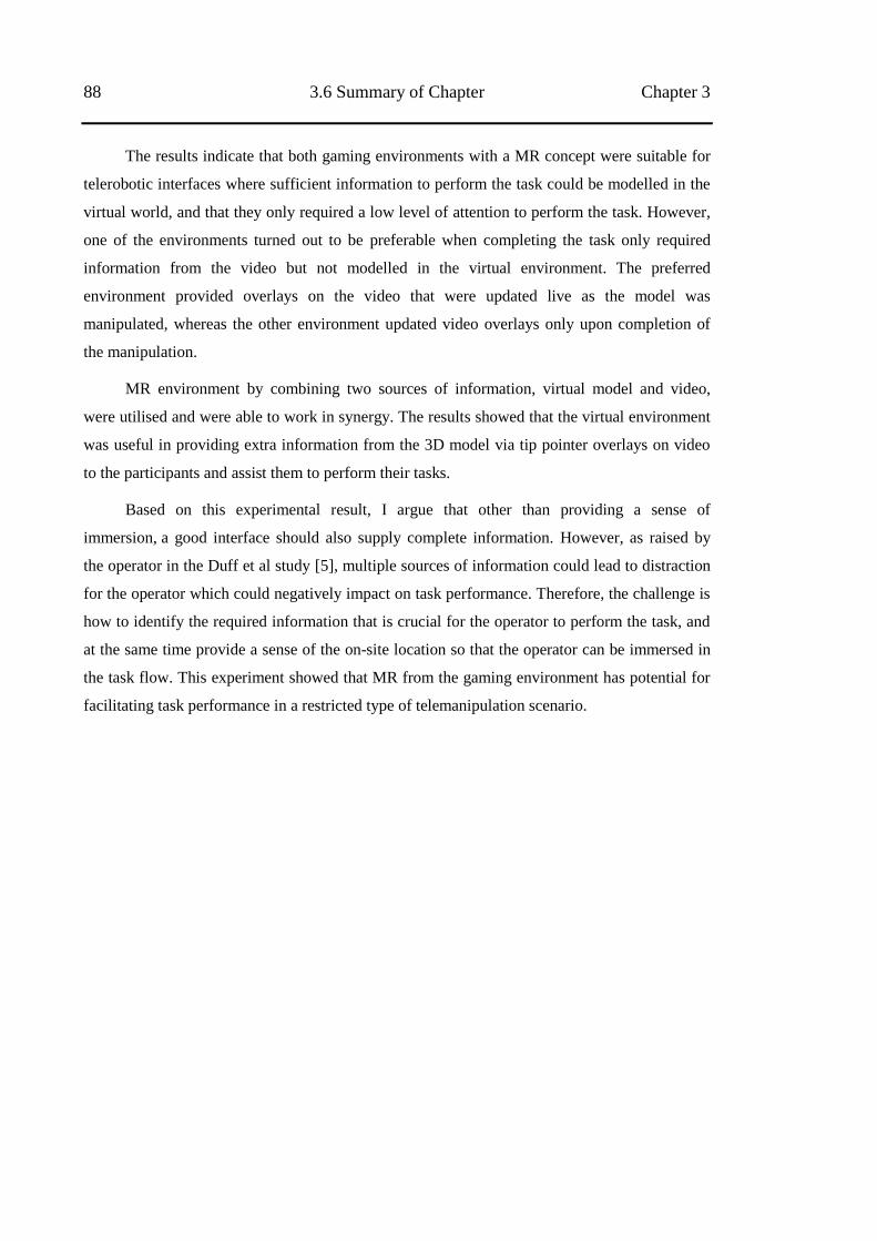
88 3.6 Summary of Chapter Chapter 3
The results indicate that both gaming environments with a MR concept were suitable for
telerobotic interfaces where sufficient information to perform the task could be modelled in the
virtual world, and that they only required a low level of attention to perform the task. However,
one of the environments turned out to be preferable when completing the task only required
information from the video but not modelled in the virtual environment. The preferred
environment provided overlays on the video that were updated live as the model was
manipulated, whereas the other environment updated video overlays only upon completion of
the manipulation.
MR environment by combining two sources of information, virtual model and video,
were utilised and were able to work in synergy. The results showed that the virtual environment
was useful in providing extra information from the 3D model via tip pointer overlays on video
to the participants and assist them to perform their tasks.
Based on this experimental result, I argue that other than providing a sense of
immersion, a good interface should also supply complete information. However, as raised by
the operator in the Duff et al study [5], multiple sources of information could lead to distraction
for the operator which could negatively impact on task performance. Therefore, the challenge is
how to identify the required information that is crucial for the operator to perform the task, and
at the same time provide a sense of the on-site location so that the operator can be immersed in
the task flow. This experiment showed that MR from the gaming environment has potential for
facilitating task performance in a restricted type of telemanipulation scenario.
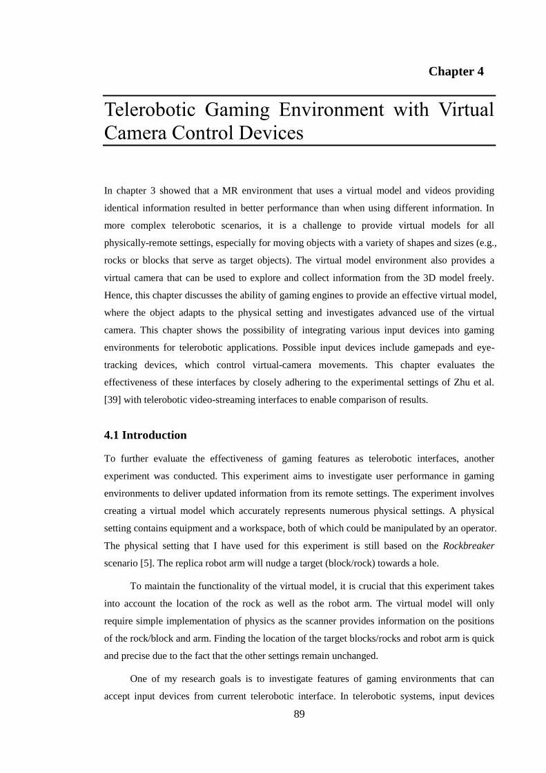
89
Chapter 4
Telerobotic Gaming Environment with Virtual
Camera Control Devices
In chapter 3 showed that a MR environment that uses a virtual model and videos providing
identical information resulted in better performance than when using different information. In
more complex telerobotic scenarios, it is a challenge to provide virtual models for all
physically-remote settings, especially for moving objects with a variety of shapes and sizes (e.g.,
rocks or blocks that serve as target objects). The virtual model environment also provides a
virtual camera that can be used to explore and collect information from the 3D model freely.
Hence, this chapter discusses the ability of gaming engines to provide an effective virtual model,
where the object adapts to the physical setting and investigates advanced use of the virtual
camera. This chapter shows the possibility of integrating various input devices into gaming
environments for telerobotic applications. Possible input devices include gamepads and eye-
tracking devices, which control virtual-camera movements. This chapter evaluates the
effectiveness of these interfaces by closely adhering to the experimental settings of Zhu et al.
[39] with telerobotic video-streaming interfaces to enable comparison of results.
4.1 Introduction
To further evaluate the effectiveness of gaming features as telerobotic interfaces, another
experiment was conducted. This experiment aims to investigate user performance in gaming
environments to deliver updated information from its remote settings. The experiment involves
creating a virtual model which accurately represents numerous physical settings. A physical
setting contains equipment and a workspace, both of which could be manipulated by an operator.
The physical setting that I have used for this experiment is still based on the Rockbreaker
scenario [5]. The replica robot arm will nudge a target (block/rock) towards a hole.
To maintain the functionality of the virtual model, it is crucial that this experiment takes
into account the location of the rock as well as the robot arm. The virtual model will only
require simple implementation of physics as the scanner provides information on the positions
of the rock/block and arm. Finding the location of the target blocks/rocks and robot arm is quick
and precise due to the fact that the other settings remain unchanged.
One of my research goals is to investigate features of gaming environments that can
accept input devices from current telerobotic interface. In telerobotic systems, input devices
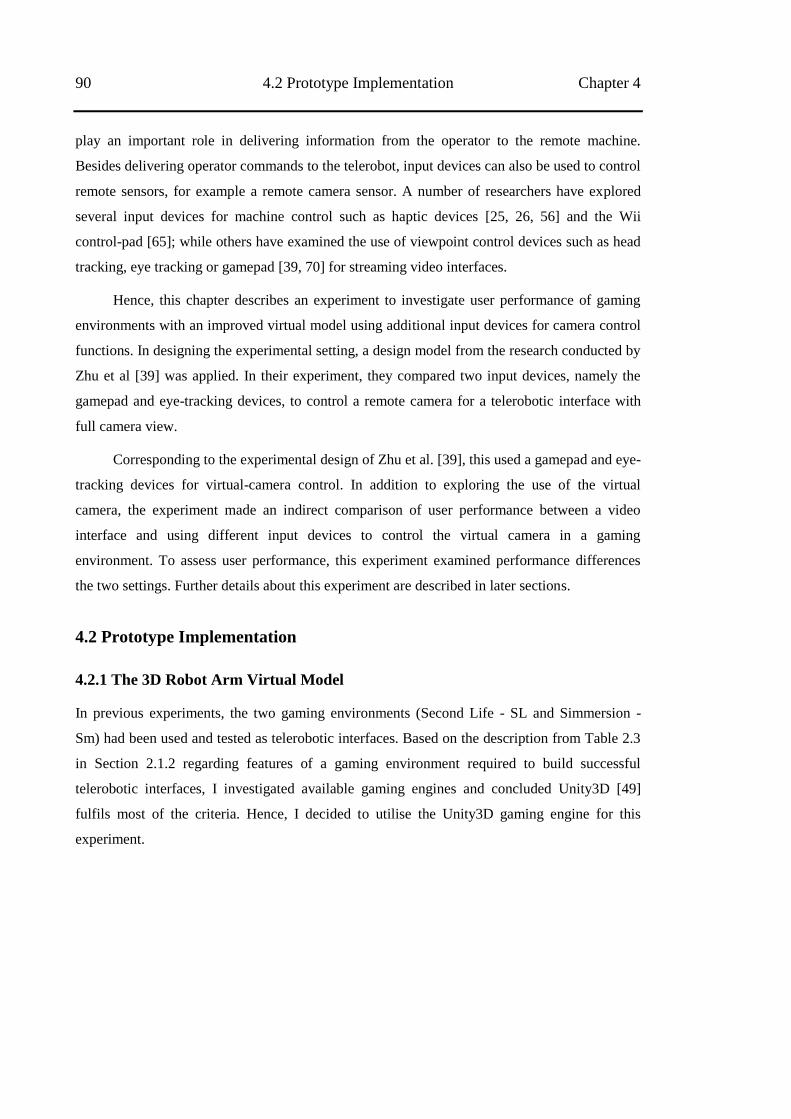
90 4.2 Prototype Implementation Chapter 4
play an important role in delivering information from the operator to the remote machine.
Besides delivering operator commands to the telerobot, input devices can also be used to control
remote sensors, for example a remote camera sensor. A number of researchers have explored
several input devices for machine control such as haptic devices [25, 26, 56] and the Wii
control-pad [65]; while others have examined the use of viewpoint control devices such as head
tracking, eye tracking or gamepad [39, 70] for streaming video interfaces.
Hence, this chapter describes an experiment to investigate user performance of gaming
environments with an improved virtual model using additional input devices for camera control
functions. In designing the experimental setting, a design model from the research conducted by
Zhu et al [39] was applied. In their experiment, they compared two input devices, namely the
gamepad and eye-tracking devices, to control a remote camera for a telerobotic interface with
full camera view.
Corresponding to the experimental design of Zhu et al. [39], this used a gamepad and eye-
tracking devices for virtual-camera control. In addition to exploring the use of the virtual
camera, the experiment made an indirect comparison of user performance between a video
interface and using different input devices to control the virtual camera in a gaming
environment. To assess user performance, this experiment examined performance differences
the two settings. Further details about this experiment are described in later sections.
4.2 Prototype Implementation
4.2.1 The 3D Robot Arm Virtual Model
In previous experiments, the two gaming environments (Second Life - SL and Simmersion -
Sm) had been used and tested as telerobotic interfaces. Based on the description from Table 2.3
in Section 2.1.2 regarding features of a gaming environment required to build successful
telerobotic interfaces, I investigated available gaming engines and concluded Unity3D [49]
fulfils most of the criteria. Hence, I decided to utilise the Unity3D gaming engine for this
experiment.
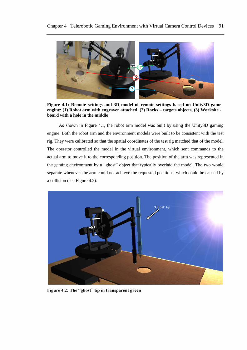
Chapter 4 Telerobotic Gaming Environment with Virtual Camera Control Devices 91
Figure 4.1: Remote settings and 3D model of remote settings based on Unity3D game
engine: (1) Robot arm with engraver attached, (2) Rocks – targets objects, (3) Worksite -
board with a hole in the middle
As shown in Figure 4.1, the robot arm model was built by using the Unity3D gaming
engine. Both the robot arm and the environment models were built to be consistent with the test
rig. They were calibrated so that the spatial coordinates of the test rig matched that of the model.
The operator controlled the model in the virtual environment, which sent commands to the
actual arm to move it to the corresponding position. The position of the arm was represented in
the gaming environment by a ―ghost‖ object that typically overlaid the model. The two would
separate whenever the arm could not achieve the requested positions, which could be caused by
a collision (see Figure 4.2).
Figure 4.2: The “ghost” tip in transparent green
„Ghost‘ tip
3
1
2
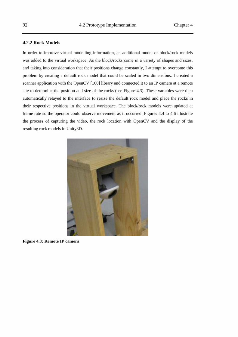
92 4.2 Prototype Implementation Chapter 4
4.2.2 Rock Models
In order to improve virtual modelling information, an additional model of block/rock models
was added to the virtual workspace. As the block/rocks come in a variety of shapes and sizes,
and taking into consideration that their positions change constantly, I attempt to overcome this
problem by creating a default rock model that could be scaled in two dimensions. I created a
scanner application with the OpenCV [100] library and connected it to an IP camera at a remote
site to determine the position and size of the rocks (see Figure 4.3). These variables were then
automatically relayed to the interface to resize the default rock model and place the rocks in
their respective positions in the virtual workspace. The block/rock models were updated at
frame rate so the operator could observe movement as it occurred. Figures 4.4 to 4.6 illustrate
the process of capturing the video, the rock location with OpenCV and the display of the
resulting rock models in Unity3D.
Figure 4.3: Remote IP camera
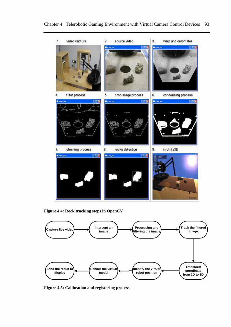
Chapter 4 Telerobotic Gaming Environment with Virtual Camera Control Devices 93
Figure 4.4: Rock tracking steps in OpenCV
Capture live videoIntercept an
image
Processing and
filtering the image
Track the filtered
image
Send the result to
display
Render the virtual
model
Identify the virtual
robot position
Transform
coordinate
from 2D to 3D
Figure 4.5: Calibration and registering process
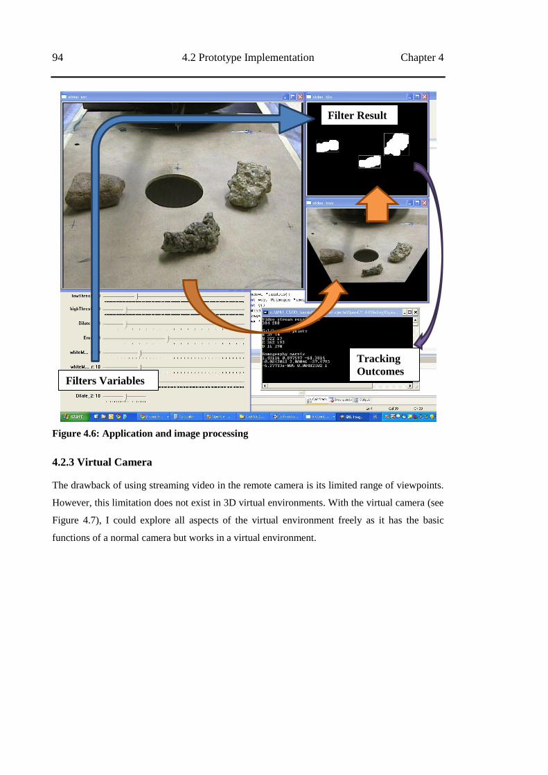
94 4.2 Prototype Implementation Chapter 4
Figure 4.6: Application and image processing
4.2.3 Virtual Camera
The drawback of using streaming video in the remote camera is its limited range of viewpoints.
However, this limitation does not exist in 3D virtual environments. With the virtual camera (see
Figure 4.7), I could explore all aspects of the virtual environment freely as it has the basic
functions of a normal camera but works in a virtual environment.
Filters Variables
Filter Result
Tracking
Outcomes
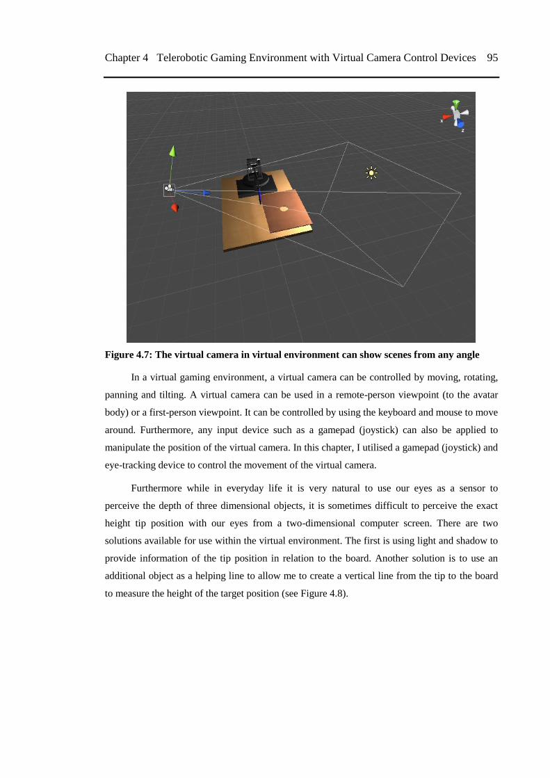
Chapter 4 Telerobotic Gaming Environment with Virtual Camera Control Devices 95
Figure 4.7: The virtual camera in virtual environment can show scenes from any angle
In a virtual gaming environment, a virtual camera can be controlled by moving, rotating,
panning and tilting. A virtual camera can be used in a remote-person viewpoint (to the avatar
body) or a first-person viewpoint. It can be controlled by using the keyboard and mouse to move
around. Furthermore, any input device such as a gamepad (joystick) can also be applied to
manipulate the position of the virtual camera. In this chapter, I utilised a gamepad (joystick) and
eye-tracking device to control the movement of the virtual camera.
Furthermore while in everyday life it is very natural to use our eyes as a sensor to
perceive the depth of three dimensional objects, it is sometimes difficult to perceive the exact
height tip position with our eyes from a two-dimensional computer screen. There are two
solutions available for use within the virtual environment. The first is using light and shadow to
provide information of the tip position in relation to the board. Another solution is to use an
additional object as a helping line to allow me to create a vertical line from the tip to the board
to measure the height of the target position (see Figure 4.8).
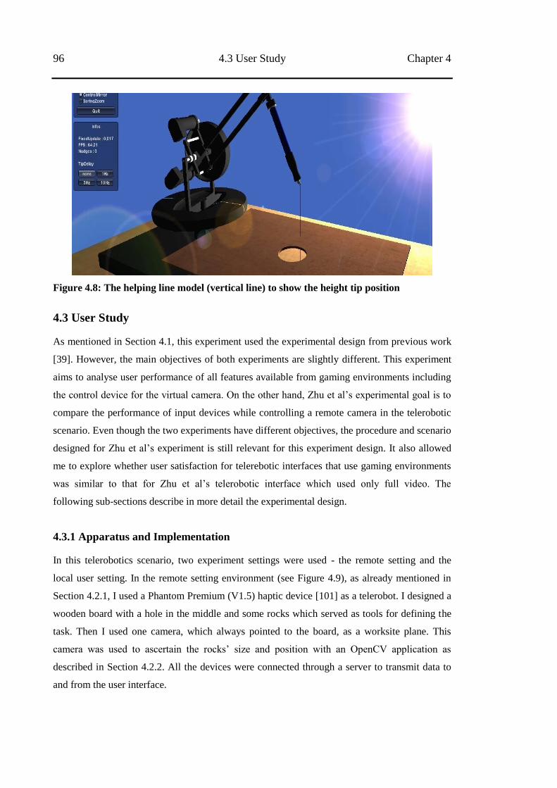
96 4.3 User Study Chapter 4
Figure 4.8: The helping line model (vertical line) to show the height tip position
4.3 User Study
As mentioned in Section 4.1, this experiment used the experimental design from previous work
[39]. However, the main objectives of both experiments are slightly different. This experiment
aims to analyse user performance of all features available from gaming environments including
the control device for the virtual camera. On the other hand, Zhu et al‘s experimental goal is to
compare the performance of input devices while controlling a remote camera in the telerobotic
scenario. Even though the two experiments have different objectives, the procedure and scenario
designed for Zhu et al‘s experiment is still relevant for this experiment design. It also allowed
me to explore whether user satisfaction for telerebotic interfaces that use gaming environments
was similar to that for Zhu et al‘s telerobotic interface which used only full video. The
following sub-sections describe in more detail the experimental design.
4.3.1 Apparatus and Implementation
In this telerobotics scenario, two experiment settings were used - the remote setting and the
local user setting. In the remote setting environment (see Figure 4.9), as already mentioned in
Section 4.2.1, I used a Phantom Premium (V1.5) haptic device [101] as a telerobot. I designed a
wooden board with a hole in the middle and some rocks which served as tools for defining the
task. Then I used one camera, which always pointed to the board, as a worksite plane. This
camera was used to ascertain the rocks‘ size and position with an OpenCV application as
described in Section 4.2.2. All the devices were connected through a server to transmit data to
and from the user interface.
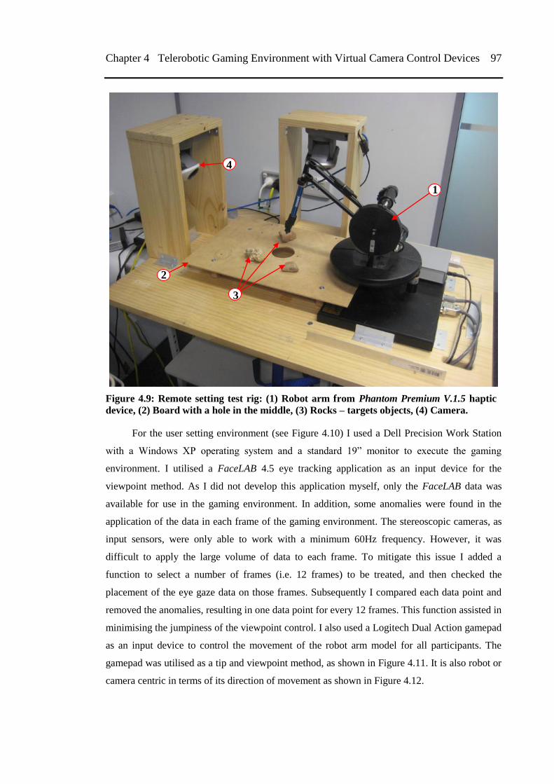
Chapter 4 Telerobotic Gaming Environment with Virtual Camera Control Devices 97
Figure 4.9: Remote setting test rig: (1) Robot arm from Phantom Premium V.1.5 haptic
device, (2) Board with a hole in the middle, (3) Rocks – targets objects, (4) Camera.
For the user setting environment (see Figure 4.10) I used a Dell Precision Work Station
with a Windows XP operating system and a standard 19‖ monitor to execute the gaming
environment. I utilised a FaceLAB 4.5 eye tracking application as an input device for the
viewpoint method. As I did not develop this application myself, only the FaceLAB data was
available for use in the gaming environment. In addition, some anomalies were found in the
application of the data in each frame of the gaming environment. The stereoscopic cameras, as
input sensors, were only able to work with a minimum 60Hz frequency. However, it was
difficult to apply the large volume of data to each frame. To mitigate this issue I added a
function to select a number of frames (i.e. 12 frames) to be treated, and then checked the
placement of the eye gaze data on those frames. Subsequently I compared each data point and
removed the anomalies, resulting in one data point for every 12 frames. This function assisted in
minimising the jumpiness of the viewpoint control. I also used a Logitech Dual Action gamepad
as an input device to control the movement of the robot arm model for all participants. The
gamepad was utilised as a tip and viewpoint method, as shown in Figure 4.11. It is also robot or
camera centric in terms of its direction of movement as shown in Figure 4.12.
3
2
1
4
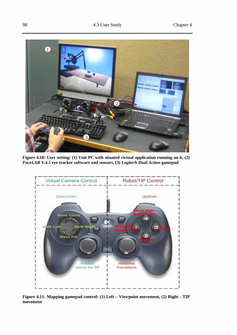
98 4.3 User Study Chapter 4
Figure 4.10: User setting: (1) Unit PC with situated virtual application running on it, (2)
FaceLAB V.4.5 eye tracker software and sensors, (3) Logitech Dual Action gamepad
Figure 4.11: Mapping gamepad control: (1) Left – Viewpoint movement, (2) Right - TIP
movement
1
2
3
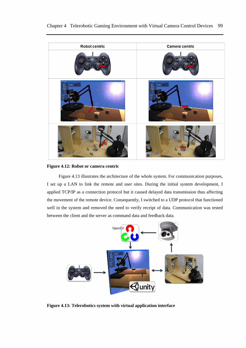
Chapter 4 Telerobotic Gaming Environment with Virtual Camera Control Devices 99
Figure 4.12: Robot or camera centric
Figure 4.13 illustrates the architecture of the whole system. For communication purposes,
I set up a LAN to link the remote and user sites. During the initial system development, I
applied TCP/IP as a connection protocol but it caused delayed data transmission thus affecting
the movement of the remote device. Consequently, I switched to a UDP protocol that functioned
well in the system and removed the need to verify receipt of data. Communication was tested
between the client and the server as command data and feedback data.
Figure 4.13: Telerobotics system with virtual application interface
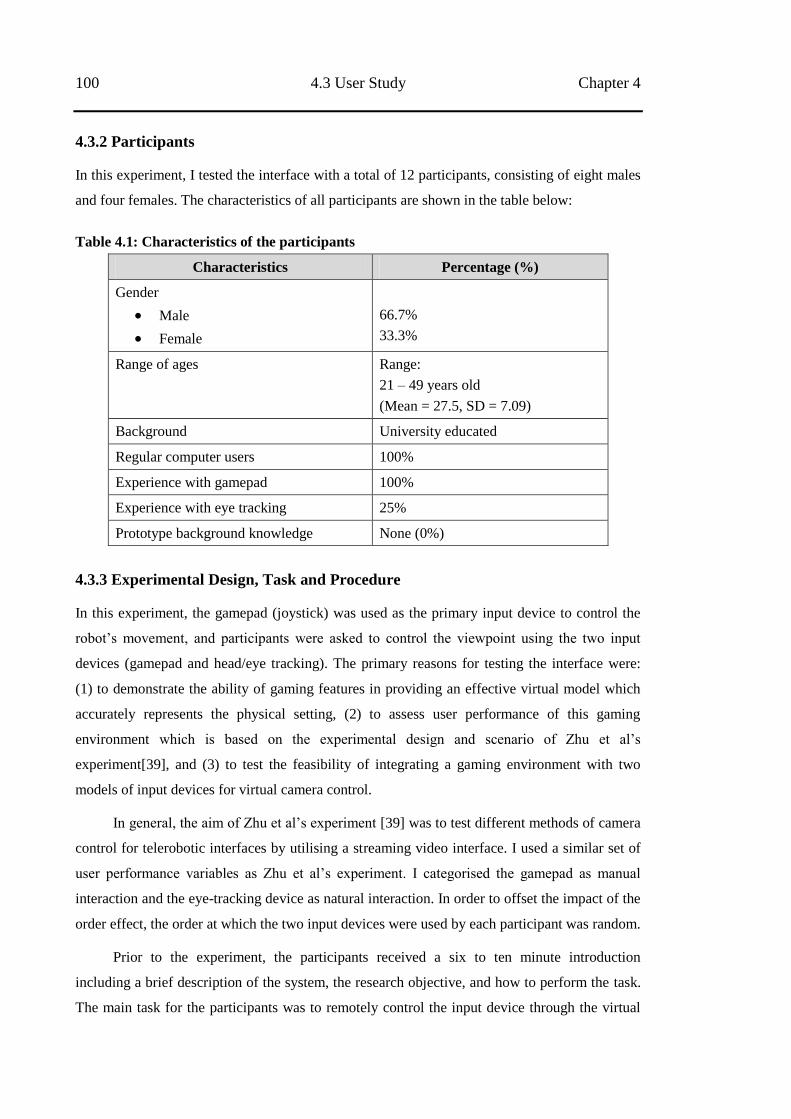
100 4.3 User Study Chapter 4
4.3.2 Participants
In this experiment, I tested the interface with a total of 12 participants, consisting of eight males
and four females. The characteristics of all participants are shown in the table below:
Table 4.1: Characteristics of the participants
Characteristics Percentage (%)
Gender
Male
Female
66.7%
33.3%
Range of ages Range:
21 – 49 years old
(Mean = 27.5, SD = 7.09)
Background University educated
Regular computer users 100%
Experience with gamepad 100%
Experience with eye tracking 25%
Prototype background knowledge None (0%)
4.3.3 Experimental Design, Task and Procedure
In this experiment, the gamepad (joystick) was used as the primary input device to control the
robot‘s movement, and participants were asked to control the viewpoint using the two input
devices (gamepad and head/eye tracking). The primary reasons for testing the interface were:
(1) to demonstrate the ability of gaming features in providing an effective virtual model which
accurately represents the physical setting, (2) to assess user performance of this gaming
environment which is based on the experimental design and scenario of Zhu et al‘s
experiment[39], and (3) to test the feasibility of integrating a gaming environment with two
models of input devices for virtual camera control.
In general, the aim of Zhu et al‘s experiment [39] was to test different methods of camera
control for telerobotic interfaces by utilising a streaming video interface. I used a similar set of
user performance variables as Zhu et al‘s experiment. I categorised the gamepad as manual
interaction and the eye-tracking device as natural interaction. In order to offset the impact of the
order effect, the order at which the two input devices were used by each participant was random.
Prior to the experiment, the participants received a six to ten minute introduction
including a brief description of the system, the research objective, and how to perform the task.
The main task for the participants was to remotely control the input device through the virtual
Chapter 4 Telerobotic Gaming Environment with Virtual Camera Control Devices 101
interface to control both the robot‘s movement and the camera viewpoint with the aim of
sinking the rocks into the hole. In this experiment I also applied a ―nudge function‖ [39] to push
the rock into the hole. Each participant had a total of three minutes to perform the task with each
input device. Then each three-minute time slot was further divided into three separate (60-
second) operation periods in which participants were asked to conduct the same experiment
procedure. In addition, a further three to five minutes were required for each participant to
recalibrate the eye-tracking input device prior to use.
The initial viewpoint was set to the zoom position to nudge the rock. The participants
were asked to use the zoom in/out function on the gamepad or to move their head
forward/backward to search for each rock‘s position. All participants were asked to push the
rock with the nudge function, with each nudge and rock sunk recorded as objective data for user
performance indicators. If there was no nudge in pushing the rocks, then the rock was not
recorded as being sunk. After the participants completed the formal experiment, I sought
feedback regarding the performance of the user interface through a questionnaire that used a
seven-point Likert-scale from one (strongly disagree) to seven (strongly agree), and a short
interview. Both five-point and seven-point scales are common scale range in Likert-scale. A
seven-point Likert-scale was used instead of the five-point scale for the rest of experiments to
obtain a greater variance in user response.
4.4 Results
To evaluate user performance using a gaming environment with improved virtual modelling and
two input devices for virtual camera control, two user performance indicators, the total number
of rocks sunk and the total number of nudges, were recorded. The results are presented in two
sub-sections based on objective and subjective data analysis. Additional discussion is also
presented to determine similarities and differences between this experiment and Zhu et al‘s
experiment [39].
4.4.1 Objective Measurement
The user performance indicators recorded are the total number of rocks sunk and the total
number of nudges. Table 4.2 shows the mean user performance in using the gamepad and eye-
tracking input devices, for virtual camera control.
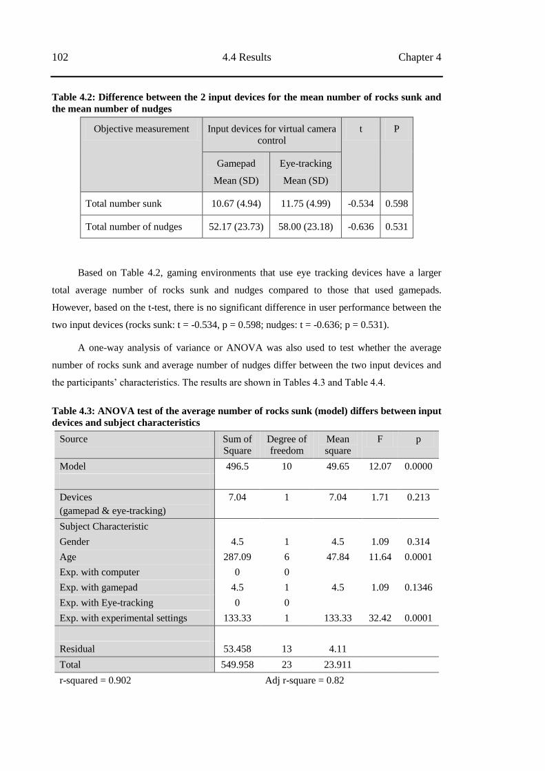
102 4.4 Results Chapter 4
Table 4.2: Difference between the 2 input devices for the mean number of rocks sunk and
the mean number of nudges
Objective measurement Input devices for virtual camera
control
t P
Gamepad
Mean (SD)
Eye-tracking
Mean (SD)
Total number sunk 10.67 (4.94) 11.75 (4.99) -0.534 0.598
Total number of nudges 52.17 (23.73) 58.00 (23.18) -0.636 0.531
Based on Table 4.2, gaming environments that use eye tracking devices have a larger
total average number of rocks sunk and nudges compared to those that used gamepads.
However, based on the t-test, there is no significant difference in user performance between the
two input devices (rocks sunk: t = -0.534, p = 0.598; nudges: t = -0.636; p = 0.531).
A one-way analysis of variance or ANOVA was also used to test whether the average
number of rocks sunk and average number of nudges differ between the two input devices and
the participants‘ characteristics. The results are shown in Tables 4.3 and Table 4.4.
Table 4.3: ANOVA test of the average number of rocks sunk (model) differs between input
devices and subject characteristics
Source Sum of
Square
Degree of
freedom
Mean
square
F p
Model 496.5 10 49.65 12.07 0.0000
Devices
(gamepad & eye-tracking)
7.04 1 7.04 1.71 0.213
Subject Characteristic
Gender 4.5 1 4.5 1.09 0.314
Age 287.09 6 47.84 11.64 0.0001
Exp. with computer 0 0
Exp. with gamepad 4.5 1 4.5 1.09 0.1346
Exp. with Eye-tracking 0 0
Exp. with experimental settings 133.33 1 133.33 32.42 0.0001
Residual 53.458 13 4.11
Total 549.958 23 23.911
r-squared = 0.902 Adj r-square = 0.82
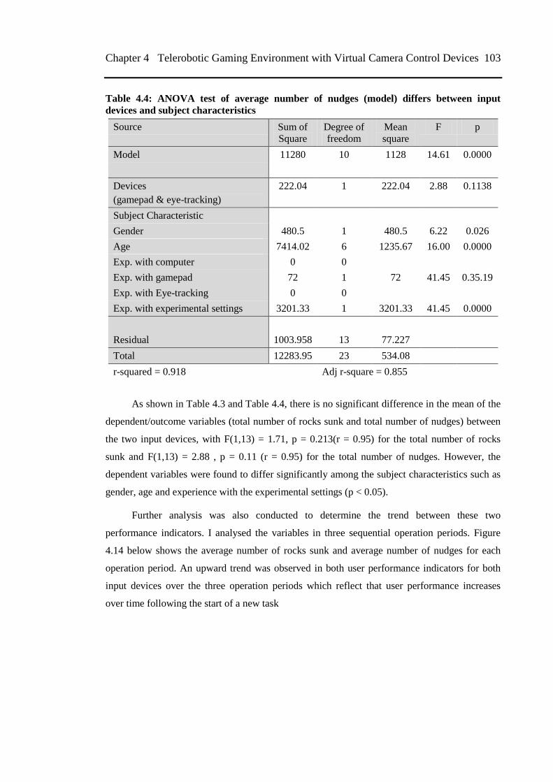
Chapter 4 Telerobotic Gaming Environment with Virtual Camera Control Devices 103
Table 4.4: ANOVA test of average number of nudges (model) differs between input
devices and subject characteristics
Source Sum of
Square
Degree of
freedom
Mean
square
F p
Model 11280 10 1128 14.61 0.0000
Devices
(gamepad & eye-tracking)
222.04 1 222.04 2.88 0.1138
Subject Characteristic
Gender 480.5 1 480.5 6.22 0.026
Age 7414.02 6 1235.67 16.00 0.0000
Exp. with computer 0 0
Exp. with gamepad 72 1 72 41.45 0.35.19
Exp. with Eye-tracking 0 0
Exp. with experimental settings 3201.33 1 3201.33 41.45 0.0000
Residual 1003.958 13 77.227
Total 12283.95 23 534.08
r-squared = 0.918 Adj r-square = 0.855
As shown in Table 4.3 and Table 4.4, there is no significant difference in the mean of the
dependent/outcome variables (total number of rocks sunk and total number of nudges) between
the two input devices, with F(1,13) = 1.71, p = 0.213(r = 0.95) for the total number of rocks
sunk and F(1,13) = 2.88 , p = 0.11 (r = 0.95) for the total number of nudges. However, the
dependent variables were found to differ significantly among the subject characteristics such as
gender, age and experience with the experimental settings (p < 0.05).
Further analysis was also conducted to determine the trend between these two
performance indicators. I analysed the variables in three sequential operation periods. Figure
4.14 below shows the average number of rocks sunk and average number of nudges for each
operation period. An upward trend was observed in both user performance indicators for both
input devices over the three operation periods which reflect that user performance increases
over time following the start of a new task
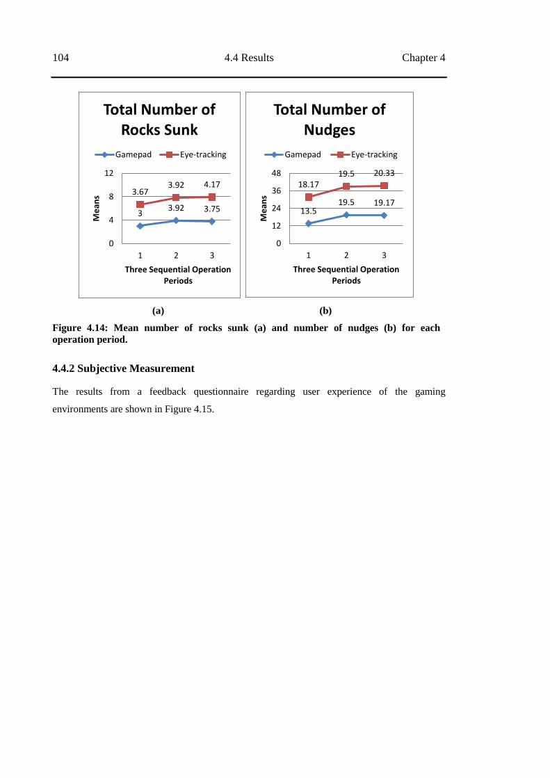
104 4.4 Results Chapter 4
(a) (b)
Figure 4.14: Mean number of rocks sunk (a) and number of nudges (b) for each
operation period.
4.4.2 Subjective Measurement
The results from a feedback questionnaire regarding user experience of the gaming
environments are shown in Figure 4.15.
3 3.92 3.75
3.67 3.92 4.17
0
4
8
12
1 2 3
Me
ans
Three Sequential Operation Periods
Total Number of Rocks Sunk
Gamepad Eye-tracking
13.5 19.5 19.17
18.17 19.5 20.33
0
12
24
36
48
1 2 3M
ean
s Three Sequential Operation
Periods
Total Number of Nudges
Gamepad Eye-tracking
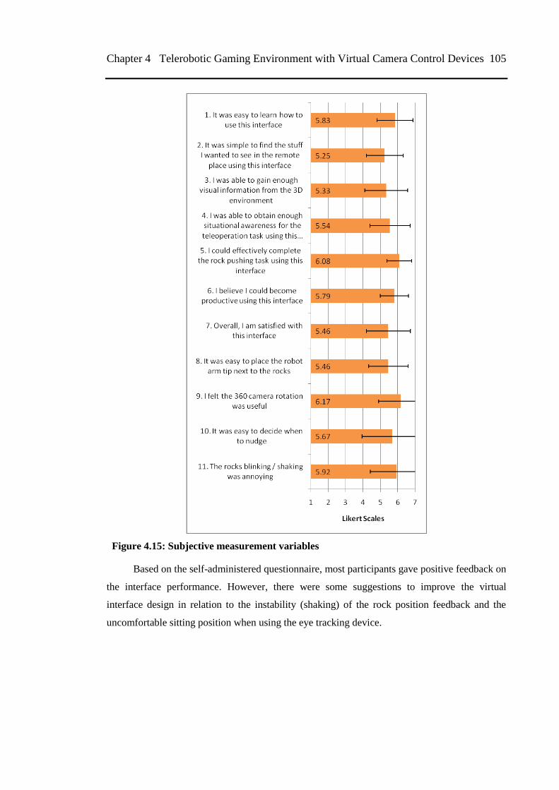
Chapter 4 Telerobotic Gaming Environment with Virtual Camera Control Devices 105
Figure 4.15: Subjective measurement variables
Based on the self-administered questionnaire, most participants gave positive feedback on
the interface performance. However, there were some suggestions to improve the virtual
interface design in relation to the instability (shaking) of the rock position feedback and the
uncomfortable sitting position when using the eye tracking device.
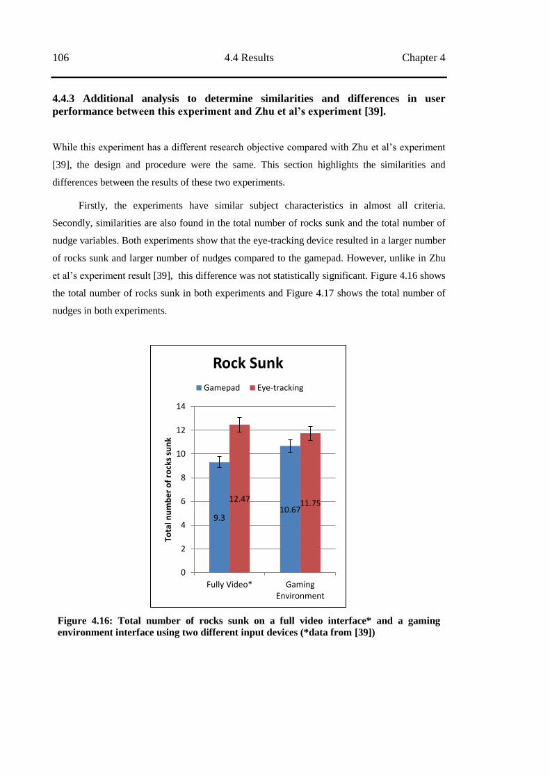
106 4.4 Results Chapter 4
4.4.3 Additional analysis to determine similarities and differences in user
performance between this experiment and Zhu et al‟s experiment [39].
While this experiment has a different research objective compared with Zhu et al‘s experiment
[39], the design and procedure were the same. This section highlights the similarities and
differences between the results of these two experiments.
Firstly, the experiments have similar subject characteristics in almost all criteria.
Secondly, similarities are also found in the total number of rocks sunk and the total number of
nudge variables. Both experiments show that the eye-tracking device resulted in a larger number
of rocks sunk and larger number of nudges compared to the gamepad. However, unlike in Zhu
et al‘s experiment result [39], this difference was not statistically significant. Figure 4.16 shows
the total number of rocks sunk in both experiments and Figure 4.17 shows the total number of
nudges in both experiments.
Figure 4.16: Total number of rocks sunk on a full video interface* and a gaming
environment interface using two different input devices (*data from [39])
9.3 10.67
12.47 11.75
0
2
4
6
8
10
12
14
Fully Video* GamingEnvironment
Tota
l nu
mb
er
of
rock
s su
nk
Rock Sunk
Gamepad Eye-tracking
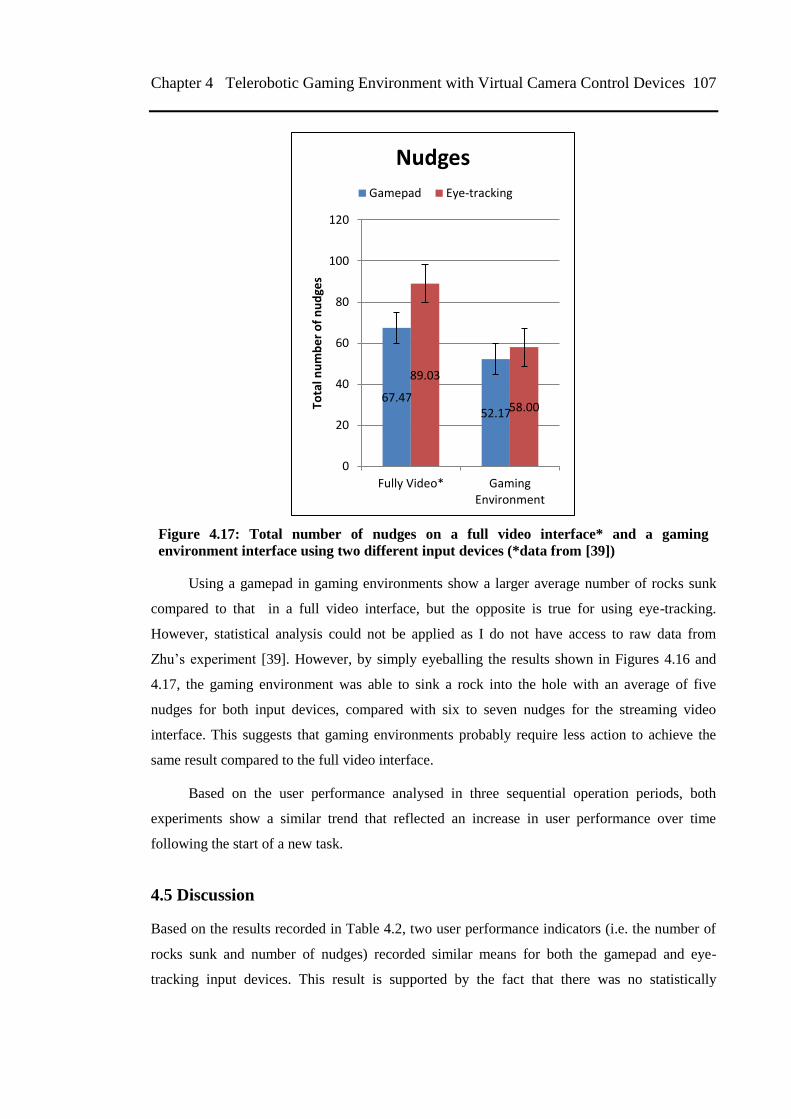
Chapter 4 Telerobotic Gaming Environment with Virtual Camera Control Devices 107
Figure 4.17: Total number of nudges on a full video interface* and a gaming
environment interface using two different input devices (*data from [39])
Using a gamepad in gaming environments show a larger average number of rocks sunk
compared to that in a full video interface, but the opposite is true for using eye-tracking.
However, statistical analysis could not be applied as I do not have access to raw data from
Zhu‘s experiment [39]. However, by simply eyeballing the results shown in Figures 4.16 and
4.17, the gaming environment was able to sink a rock into the hole with an average of five
nudges for both input devices, compared with six to seven nudges for the streaming video
interface. This suggests that gaming environments probably require less action to achieve the
same result compared to the full video interface.
Based on the user performance analysed in three sequential operation periods, both
experiments show a similar trend that reflected an increase in user performance over time
following the start of a new task.
4.5 Discussion
Based on the results recorded in Table 4.2, two user performance indicators (i.e. the number of
rocks sunk and number of nudges) recorded similar means for both the gamepad and eye-
tracking input devices. This result is supported by the fact that there was no statistically
67.47 52.17
89.03
58.00
0
20
40
60
80
100
120
Fully Video* GamingEnvironment
Tota
l nu
mb
er
of
nu
dge
s
Nudges
Gamepad Eye-tracking
108 4.6 Summary of Chapter Chapter 4
significant difference between the two devices. Hence I argue that both input devices are
suitable in gaming environments in telerobotic scenarios.
Analysis was also conducted to determine the difference in user performance by the
subjects‘ characteristics. Statistically significant differences were observed in gender, age and
experience in the experimental settings. Hence it could be concluded that the user performance
indicators is affected by the split in gender, variance in participants‘ age and their knowledge of
the experimental settings. However further analysis is needed to understand why these variables
influence performance.
Based on user performance data recorded in three sequential operation periods, the
participants were seen to show gradual improvement in subsequent operation periods. Hence I
suggest that gaming environments and virtual camera control devices are easy learning
environments, and through task repetition operators are expected to perform better over time.
Moreover, the use of different viewpoint methods did not have a large impact on the
performance of the task because the ideal condition was when a fixed camera view was used. I
expected that rotation about the tip would be better than panning but this experiment showed
that there was no significant difference.
Based on the questionnaire feedback, most participants viewed the interface performance
positively, and believed the virtual environment could improve their work efficiency. After the
experiment, most participants commented that when using the gaming environment for this
telerobotic scenario, the interface proved user friendly, easy-to-learn and fun. Based on Fong
[37, 38], interfaces which users find gratifying correlate to improved telerobotic task
performance.
4.6 Summary of Chapter
In this experiment, I observed that the gaming environment can be improved by virtual
modelling to represent physical settings. I also noted that the gaming environments have
features that can be integrated with a number of virtual camera control devices without affecting
operator performance.
After evaluating the user performances, I argue that the gaming environment is suitable
for applying two input devices for virtual camera control in a telerobotic scenario. These results
strengthened my argument that the gaming environment and telerobotic interfaces share many
similarities and therefore can be regarded as being in the same domain.
Chapter 4 Telerobotic Gaming Environment with Virtual Camera Control Devices 109
This experiment showed that in contrast to streaming video interfaces only, the gaming
environment with MR can model a remote setting effectively, provide real-time feedback of
moving objects (robot and rock), have the freedom of viewpoints from the virtual camera, and
provide other useful information (i.e., line-helper model, helper text or prediction position). The
merits of video views in MR gaming environment plays important role in completing the
missing information from the 3D model. However, based on user feedback in the questionnaire,
the rock model should be improved to achieve better performance, especially for more complex
remote settings.
This experiment has conducted further evaluation of gaming environment features that
enhance its suitability as a telerobotic interface. As mentioned in Chapter 1, one of the issues of
the telerobotic system is its communication latency. According to Domingues et al research
[75], latency in telerobots can be minimised by utilising predictive display modelling in MR or
VR environments. Another argument by Fong et al [37] mentioned that supervisory control
interfaces are well suited for applications which must work with low bandwidth communication
or in the presence of high latency. The next chapter describes an investigation on features of the
gaming environment, which can be applied to the human supervisory control (HSC) concept.

110 4.6 Summary of Chapter Chapter 4
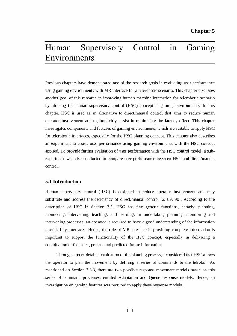
111
Chapter 5
Human Supervisory Control in Gaming
Environments
Previous chapters have demonstrated one of the research goals in evaluating user performance
using gaming environments with MR interface for a telerobotic scenario. This chapter discusses
another goal of this research in improving human machine interaction for telerobotic scenario
by utilising the human supervisory control (HSC) concept in gaming environments. In this
chapter, HSC is used as an alternative to direct/manual control that aims to reduce human
operator involvement and to, implicitly, assist in minimising the latency effect. This chapter
investigates components and features of gaming environments, which are suitable to apply HSC
for telerobotic interfaces, especially for the HSC planning concept. This chapter also describes
an experiment to assess user performance using gaming environments with the HSC concept
applied. To provide further evaluation of user performance with the HSC control model, a sub-
experiment was also conducted to compare user performance between HSC and direct/manual
control.
5.1 Introduction
Human supervisory control (HSC) is designed to reduce operator involvement and may
substitute and address the deficiency of direct/manual control [2, 89, 90]. According to the
description of HSC in Section 2.3, HSC has five generic functions, namely: planning,
monitoring, intervening, teaching, and learning. In undertaking planning, monitoring and
intervening processes, an operator is required to have a good understanding of the information
provided by interfaces. Hence, the role of MR interface in providing complete information is
important to support the functionality of the HSC concept, especially in delivering a
combination of feedback, present and predicted future information.
Through a more detailed evaluation of the planning process, I considered that HSC allows
the operator to plan the movement by defining a series of commands to the telrobot. As
mentioned on Section 2.3.3, there are two possible response movement models based on this
series of command processes, entitled Adaptation and Queue response models. Hence, an
investigation on gaming features was required to apply these response models.
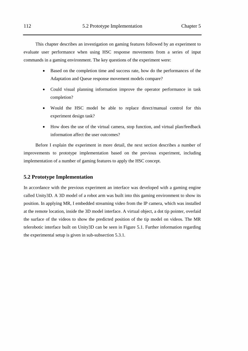
112 5.2 Prototype Implementation Chapter 5
This chapter describes an investigation on gaming features followed by an experiment to
evaluate user performance when using HSC response movements from a series of input
commands in a gaming environment. The key questions of the experiment were:
Based on the completion time and success rate, how do the performances of the
Adaptation and Queue response movement models compare?
Could visual planning information improve the operator performance in task
completion?
Would the HSC model be able to replace direct/manual control for this
experiment design task?
How does the use of the virtual camera, stop function, and virtual plan/feedback
information affect the user outcomes?
Before I explain the experiment in more detail, the next section describes a number of
improvements to prototype implementation based on the previous experiment, including
implementation of a number of gaming features to apply the HSC concept.
5.2 Prototype Implementation
In accordance with the previous experiment an interface was developed with a gaming engine
called Unity3D. A 3D model of a robot arm was built into this gaming environment to show its
position. In applying MR, I embedded streaming video from the IP camera, which was installed
at the remote location, inside the 3D model interface. A virtual object, a dot tip pointer, overlaid
the surface of the videos to show the predicted position of the tip model on videos. The MR
telerobotic interface built on Unity3D can be seen in Figure 5.1. Further information regarding
the experimental setup is given in sub-subsection 5.3.1.
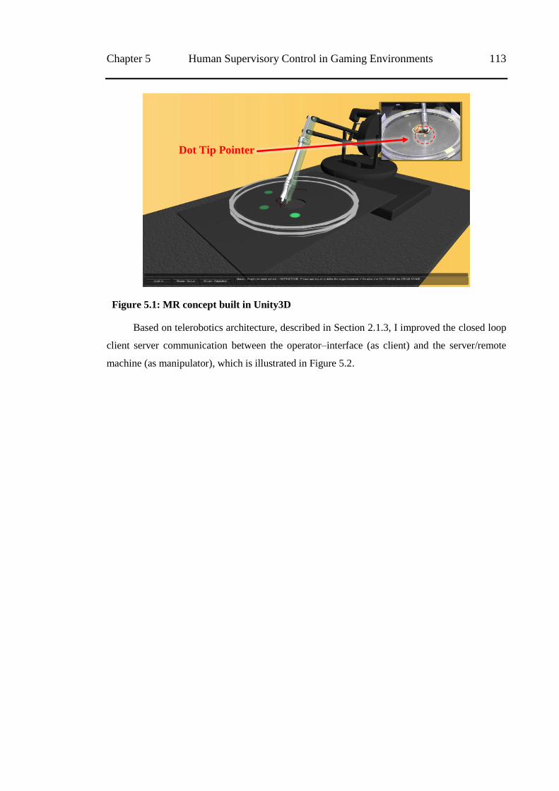
Chapter 5 Human Supervisory Control in Gaming Environments 113
Figure 5.1: MR concept built in Unity3D
Based on telerobotics architecture, described in Section 2.1.3, I improved the closed loop
client server communication between the operator–interface (as client) and the server/remote
machine (as manipulator), which is illustrated in Figure 5.2.
Dot Tip Pointer
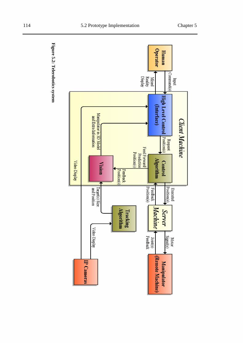
114 5.2 Prototype Implementation Chapter 5
Fig
ure
5.2
: Telero
botics sy
stem
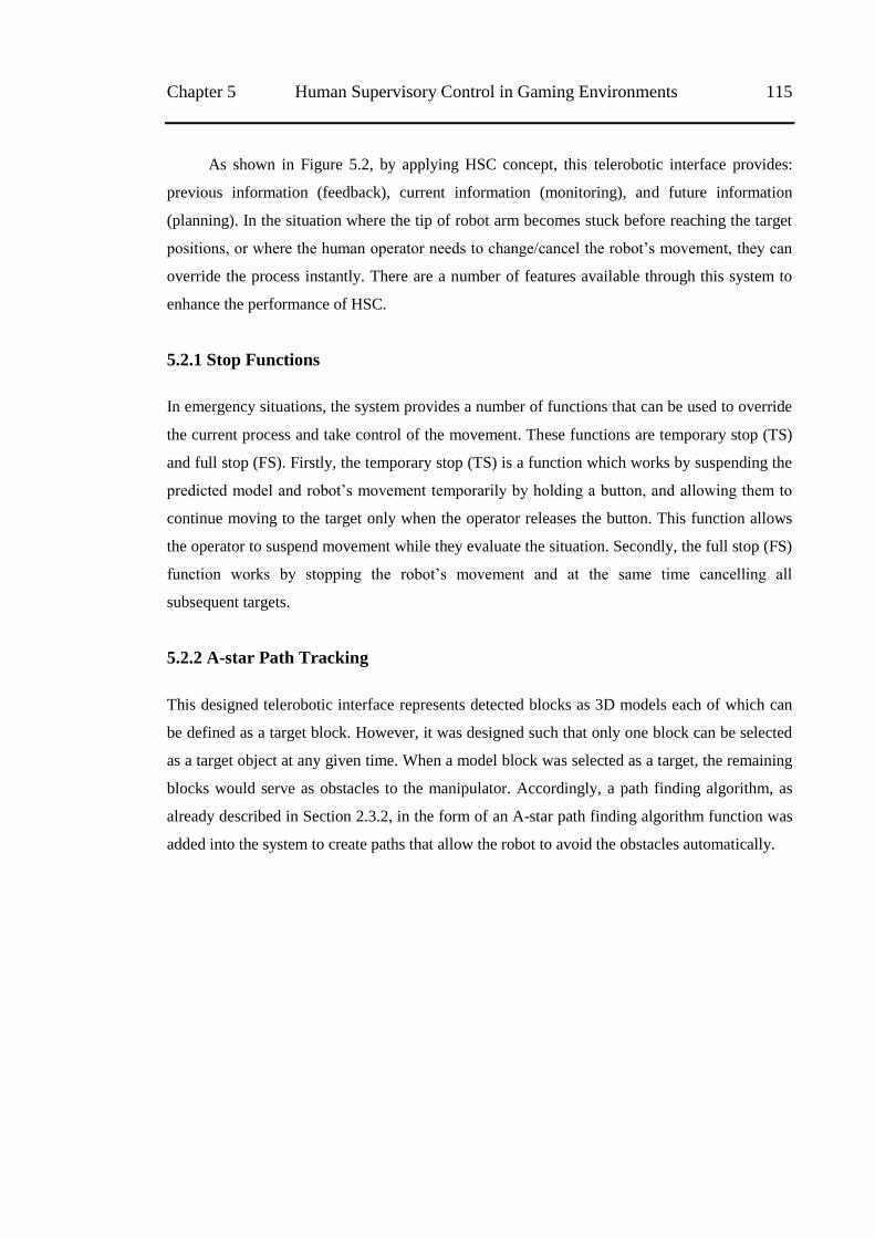
Chapter 5 Human Supervisory Control in Gaming Environments 115
As shown in Figure 5.2, by applying HSC concept, this telerobotic interface provides:
previous information (feedback), current information (monitoring), and future information
(planning). In the situation where the tip of robot arm becomes stuck before reaching the target
positions, or where the human operator needs to change/cancel the robot‘s movement, they can
override the process instantly. There are a number of features available through this system to
enhance the performance of HSC.
5.2.1 Stop Functions
In emergency situations, the system provides a number of functions that can be used to override
the current process and take control of the movement. These functions are temporary stop (TS)
and full stop (FS). Firstly, the temporary stop (TS) is a function which works by suspending the
predicted model and robot‘s movement temporarily by holding a button, and allowing them to
continue moving to the target only when the operator releases the button. This function allows
the operator to suspend movement while they evaluate the situation. Secondly, the full stop (FS)
function works by stopping the robot‘s movement and at the same time cancelling all
subsequent targets.
5.2.2 A-star Path Tracking
This designed telerobotic interface represents detected blocks as 3D models each of which can
be defined as a target block. However, it was designed such that only one block can be selected
as a target object at any given time. When a model block was selected as a target, the remaining
blocks would serve as obstacles to the manipulator. Accordingly, a path finding algorithm, as
already described in Section 2.3.2, in the form of an A-star path finding algorithm function was
added into the system to create paths that allow the robot to avoid the obstacles automatically.
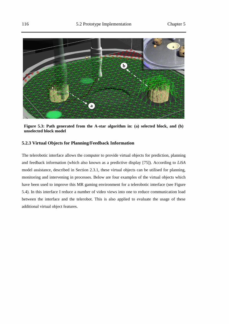
116 5.2 Prototype Implementation Chapter 5
Figure 5.3: Path generated from the A-star algorithm in: (a) selected block, and (b)
unselected block model
5.2.3 Virtual Objects for Planning/Feedback Information
The telerobotic interface allows the computer to provide virtual objects for prediction, planning
and feedback information (which also known as a predictive display [75]). According to LiSA
model assistance, described in Section 2.3.1, these virtual objects can be utilised for planning,
monitoring and intervening in processes. Below are four examples of the virtual objects which
have been used to improve this MR gaming environment for a telerobotic interface (see Figure
5.4). In this interface I reduce a number of video views into one to reduce communication load
between the interface and the telerobot. This is also applied to evaluate the usage of these
additional virtual object features.
a
b
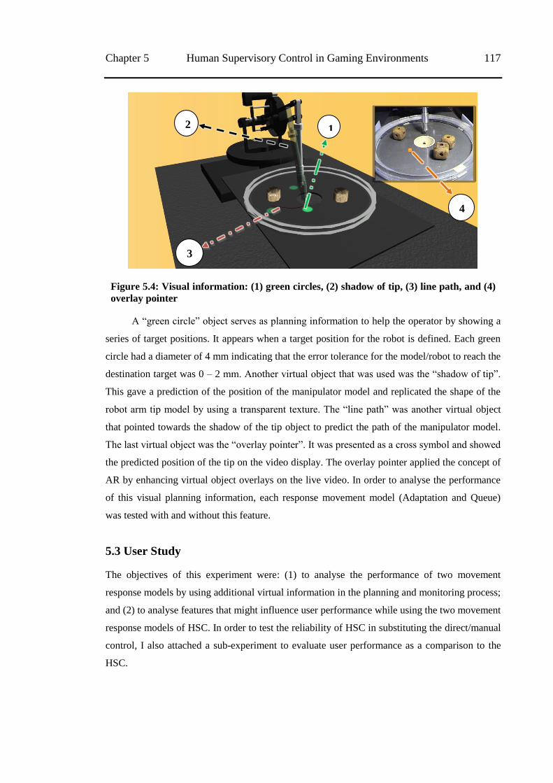
Chapter 5 Human Supervisory Control in Gaming Environments 117
Figure 5.4: Visual information: (1) green circles, (2) shadow of tip, (3) line path, and (4)
overlay pointer
A ―green circle‖ object serves as planning information to help the operator by showing a
series of target positions. It appears when a target position for the robot is defined. Each green
circle had a diameter of 4 mm indicating that the error tolerance for the model/robot to reach the
destination target was 0 – 2 mm. Another virtual object that was used was the ―shadow of tip‖.
This gave a prediction of the position of the manipulator model and replicated the shape of the
robot arm tip model by using a transparent texture. The ―line path‖ was another virtual object
that pointed towards the shadow of the tip object to predict the path of the manipulator model.
The last virtual object was the ―overlay pointer‖. It was presented as a cross symbol and showed
the predicted position of the tip on the video display. The overlay pointer applied the concept of
AR by enhancing virtual object overlays on the live video. In order to analyse the performance
of this visual planning information, each response movement model (Adaptation and Queue)
was tested with and without this feature.
5.3 User Study
The objectives of this experiment were: (1) to analyse the performance of two movement
response models by using additional virtual information in the planning and monitoring process;
and (2) to analyse features that might influence user performance while using the two movement
response models of HSC. In order to test the reliability of HSC in substituting the direct/manual
control, I also attached a sub-experiment to evaluate user performance as a comparison to the
HSC.
1 2
3
4
118 5.3 User Study Chapter 5
5.3.1 Experimental Setup
Based on the results from the previous experiment, I determined that the Unity3D gaming
engine offers a sophisticated environment compare to the other two. It allowed me to use more
gaming features to build the telerobotic interface with MR and HSC concepts applied. Similar to
the setup of the previous experiment, I set this system into local and remote areas.
Remote Machine
2 x PTZ Cameras
Remote Workspace
And
Block Targets
Mixed Reality
Interface
Input Devices:
Keyboard & Mouse
Human Operator
Figure 5.5: Experimental setup for third experiment
As shown in Figure 5.5, the local area consists of a personal computer connected to a 32‖
monitor Dell with a resolution of 2560 x 1600 pixels as a display. A standard keyboard and
mouse were used as the input devices to deliver the user‘s commands through the interface. A
telerobotic interface with MR environment and HSC was applied in this local machine.
A computer server was located at the remote area; which delivered information between
the user machine and the remote manipulator. A 3-DOF (degree of freedom) modified robot arm
served as the remote manipulator. The robot arm was located on a stage with a hole representing
a dump-bin in the middle of the workspace. Three blocks were provided on the workspace stage
as objects targeted for sinking into the hole. Similar to the previous experiment, the IP cameras
(external camera) were installed in static positions at the front and side of the telerobot and
facing the workspace stage. However, in this experimental scenario, to apply MR and reduce
distraction from multiple camera views, only the front camera was utilised and embedded inside
the telerobotic interface. In addition to providing streaming video to the interface, the camera
also connected to the server to serve as a tracking sensor and provide updates on the position of
the target objects through image analysis.
The interface used for the experiment provides information from both the camera view
and the 3D model. The embedded camera provides information regarding what is really
happening at the remote location before and after giving commands to the telerobot; it provides
any additional information if any is missing from the 3D model view (e.g. different number or
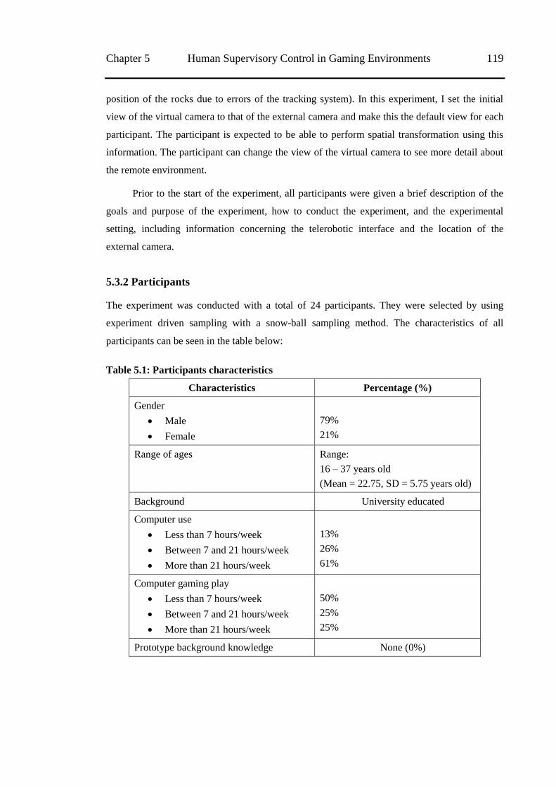
Chapter 5 Human Supervisory Control in Gaming Environments 119
position of the rocks due to errors of the tracking system). In this experiment, I set the initial
view of the virtual camera to that of the external camera and make this the default view for each
participant. The participant is expected to be able to perform spatial transformation using this
information. The participant can change the view of the virtual camera to see more detail about
the remote environment.
Prior to the start of the experiment, all participants were given a brief description of the
goals and purpose of the experiment, how to conduct the experiment, and the experimental
setting, including information concerning the telerobotic interface and the location of the
external camera.
5.3.2 Participants
The experiment was conducted with a total of 24 participants. They were selected by using
experiment driven sampling with a snow-ball sampling method. The characteristics of all
participants can be seen in the table below:
Table 5.1: Participants characteristics
Characteristics Percentage (%)
Gender
Male
Female
79%
21%
Range of ages Range:
16 – 37 years old
(Mean = 22.75, SD = 5.75 years old)
Background University educated
Computer use
Less than 7 hours/week
Between 7 and 21 hours/week
More than 21 hours/week
13%
26%
61%
Computer gaming play
Less than 7 hours/week
Between 7 and 21 hours/week
More than 21 hours/week
50%
25%
25%
Prototype background knowledge None (0%)
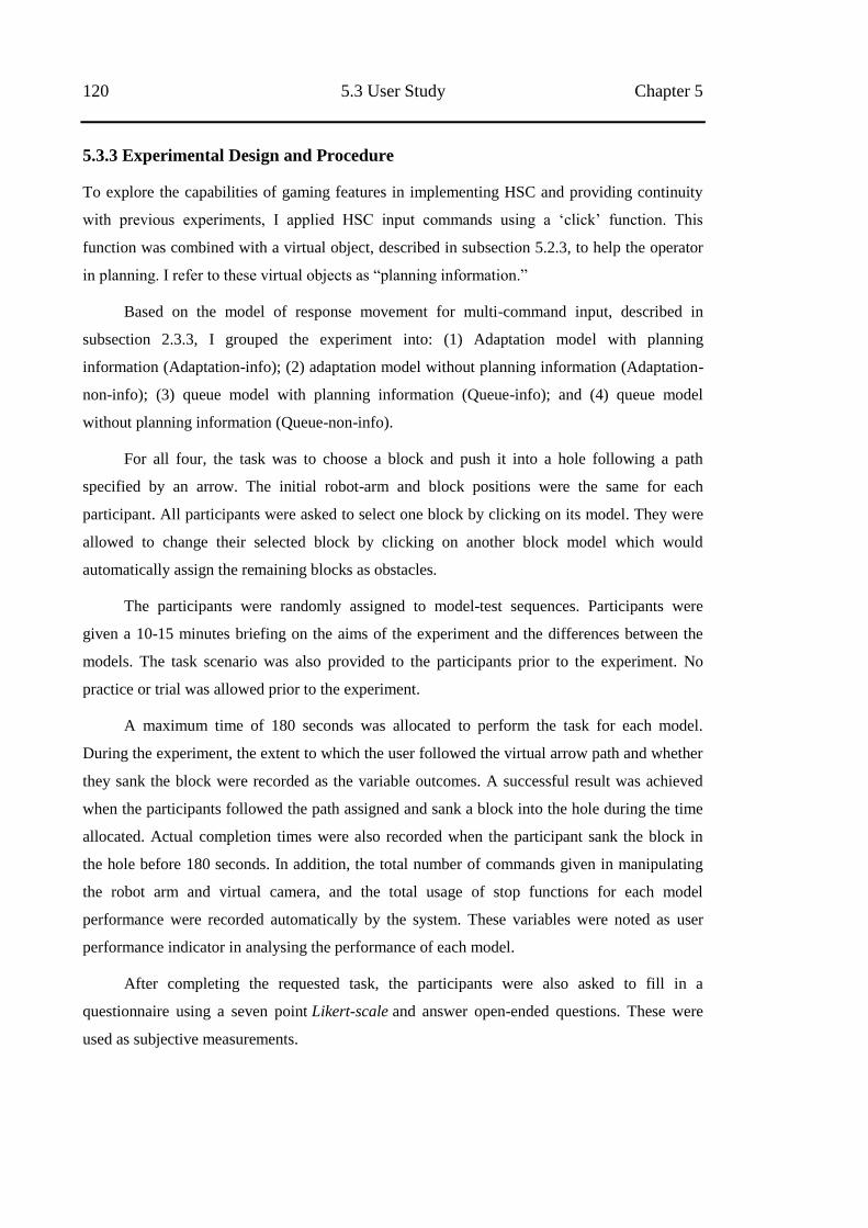
120 5.3 User Study Chapter 5
5.3.3 Experimental Design and Procedure
To explore the capabilities of gaming features in implementing HSC and providing continuity
with previous experiments, I applied HSC input commands using a ‗click‘ function. This
function was combined with a virtual object, described in subsection 5.2.3, to help the operator
in planning. I refer to these virtual objects as ―planning information.‖
Based on the model of response movement for multi-command input, described in
subsection 2.3.3, I grouped the experiment into: (1) Adaptation model with planning
information (Adaptation-info); (2) adaptation model without planning information (Adaptation-
non-info); (3) queue model with planning information (Queue-info); and (4) queue model
without planning information (Queue-non-info).
For all four, the task was to choose a block and push it into a hole following a path
specified by an arrow. The initial robot-arm and block positions were the same for each
participant. All participants were asked to select one block by clicking on its model. They were
allowed to change their selected block by clicking on another block model which would
automatically assign the remaining blocks as obstacles.
The participants were randomly assigned to model-test sequences. Participants were
given a 10-15 minutes briefing on the aims of the experiment and the differences between the
models. The task scenario was also provided to the participants prior to the experiment. No
practice or trial was allowed prior to the experiment.
A maximum time of 180 seconds was allocated to perform the task for each model.
During the experiment, the extent to which the user followed the virtual arrow path and whether
they sank the block were recorded as the variable outcomes. A successful result was achieved
when the participants followed the path assigned and sank a block into the hole during the time
allocated. Actual completion times were also recorded when the participant sank the block in
the hole before 180 seconds. In addition, the total number of commands given in manipulating
the robot arm and virtual camera, and the total usage of stop functions for each model
performance were recorded automatically by the system. These variables were noted as user
performance indicator in analysing the performance of each model.
After completing the requested task, the participants were also asked to fill in a
questionnaire using a seven point Likert-scale and answer open-ended questions. These were
used as subjective measurements.
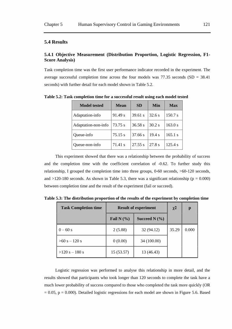
Chapter 5 Human Supervisory Control in Gaming Environments 121
5.4 Results
5.4.1 Objective Measurement (Distribution Proportion, Logistic Regression, F1-
Score Analysis)
Task completion time was the first user performance indicator recorded in the experiment. The
average successful completion time across the four models was 77.35 seconds (SD = 38.41
seconds) with further detail for each model shown in Table 5.2.
Table 5.2: Task completion time for a successful result using each model tested
Model tested Mean SD Min Max
Adaptation-info 91.49 s 39.61 s 32.6 s 150.7 s
Adaptation-non-info 73.75 s 36.58 s 30.2 s 163.0 s
Queue-info 75.15 s 37.66 s 19.4 s 165.1 s
Queue-non-info 71.41 s 27.55 s 27.8 s 125.4 s
This experiment showed that there was a relationship between the probability of success
and the completion time with the coefficient correlation of -0.62. To further study this
relationship, I grouped the completion time into three groups, 0-60 seconds, >60-120 seconds,
and >120-180 seconds. As shown in Table 5.3, there was a significant relationship (p = 0.000)
between completion time and the result of the experiment (fail or succeed).
Table 5.3: The distribution proportion of the results of the experiment by completion time
Task Completion time Result of experiment χ2 p
Fail N (%) Succeed N (%)
0 – 60 s 2 (5.88) 32 (94.12) 35.29 0.000
>60 s – 120 s 0 (0.00) 34 (100.00)
>120 s – 180 s 15 (53.57) 13 (46.43)
Logistic regression was performed to analyse this relationship in more detail, and the
results showed that participants who took longer than 120 seconds to complete the task have a
much lower probability of success compared to those who completed the task more quickly (OR
= 0.05, p = 0.000). Detailed logistic regressions for each model are shown in Figure 5.6. Based
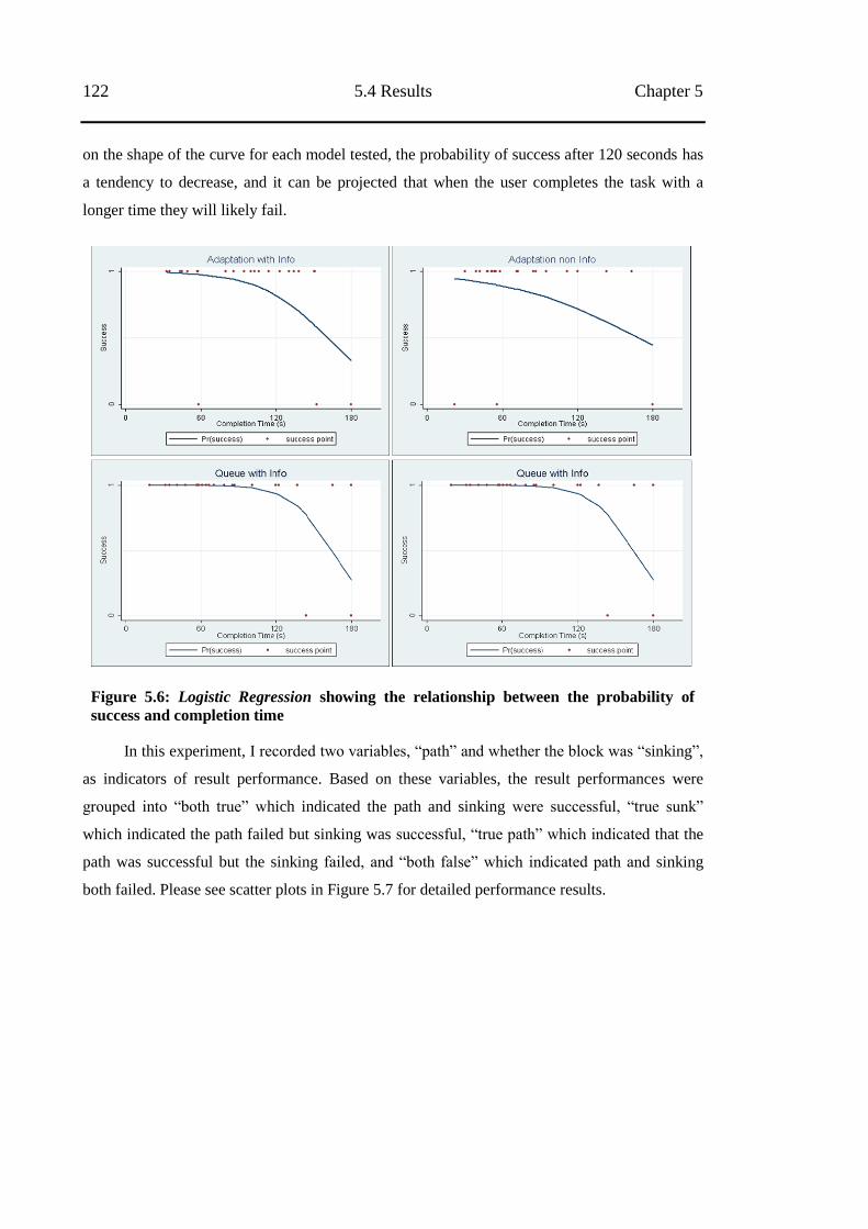
122 5.4 Results Chapter 5
on the shape of the curve for each model tested, the probability of success after 120 seconds has
a tendency to decrease, and it can be projected that when the user completes the task with a
longer time they will likely fail.
Figure 5.6: Logistic Regression showing the relationship between the probability of
success and completion time
In this experiment, I recorded two variables, ―path‖ and whether the block was ―sinking‖,
as indicators of result performance. Based on these variables, the result performances were
grouped into ―both true‖ which indicated the path and sinking were successful, ―true sunk‖
which indicated the path failed but sinking was successful, ―true path‖ which indicated that the
path was successful but the sinking failed, and ―both false‖ which indicated path and sinking
both failed. Please see scatter plots in Figure 5.7 for detailed performance results.
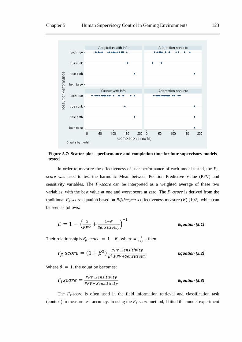
Chapter 5 Human Supervisory Control in Gaming Environments 123
Figure 5.7: Scatter plot – performance and completion time for four supervisory models
tested
In order to measure the effectiveness of user performance of each model tested, the F1-
score was used to test the harmonic Mean between Position Predictive Value (PPV) and
sensitivity variables. The F1-score can be interpreted as a weighted average of these two
variables, with the best value at one and worst score at zero. The F1-score is derived from the
traditional Fβ-score equation based on Rijsbergen’s effectiveness measure [102], which can
be seen as follows:
(
)
Equation (5.1)
Their relationship is – , where
, then
Equation (5.2)
Where , the equation becomes:
Equation (5.3)
The F1-score is often used in the field information retrieval and classification task
(context) to measure test accuracy. In using the F1-score method, I fitted this model experiment
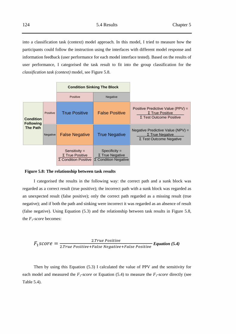
124 5.4 Results Chapter 5
into a classification task (context) model approach. In this model, I tried to measure how the
participants could follow the instruction using the interfaces with different model response and
information feedback (user performance for each model interface tested). Based on the results of
user performance, I categorised the task result to fit into the group classification for the
classification task (context) model, see Figure 5.8.
Condition
Following
The Path
Positive
Negative
True Positive
False Negative
False Positive
True Negative
Positive Predictive Value (PPV) =
Σ True Positive
Σ Test Outcome Positive
Negative Predictive Value (NPV) =
Σ True Negative
Σ Test Outcome Negative
Sensitivity =
Σ True Positive
Σ Condition Positive
Specificity =
Σ True Negative
Σ Condition Negative
Positive Negative
Condition Sinking The Block
Figure 5.8: The relationship between task results
I categorised the results in the following way: the correct path and a sunk block was
regarded as a correct result (true positive); the incorrect path with a sunk block was regarded as
an unexpected result (false positive); only the correct path regarded as a missing result (true
negative); and if both the path and sinking were incorrect it was regarded as an absence of result
(false negative). Using Equation (5.3) and the relationship between task results in Figure 5.8,
the F1-score becomes:
Equation (5.4)
Then by using this Equation (5.3) I calculated the value of PPV and the sensitivity for
each model and measured the F1-score or Equation (5.4) to measure the F1-score directly (see
Table 5.4).
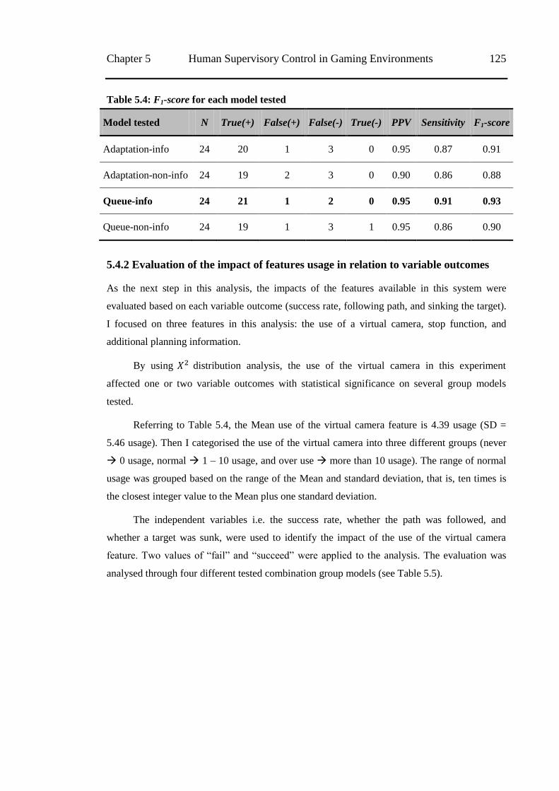
Chapter 5 Human Supervisory Control in Gaming Environments 125
Table 5.4: F1-score for each model tested
Model tested N True(+) False(+) False(-) True(-) PPV Sensitivity F1-score
Adaptation-info 24 20 1 3 0 0.95 0.87 0.91
Adaptation-non-info 24 19 2 3 0 0.90 0.86 0.88
Queue-info 24 21 1 2 0 0.95 0.91 0.93
Queue-non-info 24 19 1 3 1 0.95 0.86 0.90
5.4.2 Evaluation of the impact of features usage in relation to variable outcomes
As the next step in this analysis, the impacts of the features available in this system were
evaluated based on each variable outcome (success rate, following path, and sinking the target).
I focused on three features in this analysis: the use of a virtual camera, stop function, and
additional planning information.
By using distribution analysis, the use of the virtual camera in this experiment
affected one or two variable outcomes with statistical significance on several group models
tested.
Referring to Table 5.4, the Mean use of the virtual camera feature is 4.39 usage (SD =
5.46 usage). Then I categorised the use of the virtual camera into three different groups (never
0 usage, normal 1 – 10 usage, and over use more than 10 usage). The range of normal
usage was grouped based on the range of the Mean and standard deviation, that is, ten times is
the closest integer value to the Mean plus one standard deviation.
The independent variables i.e. the success rate, whether the path was followed, and
whether a target was sunk, were used to identify the impact of the use of the virtual camera
feature. Two values of ―fail‖ and ―succeed‖ were applied to the analysis. The evaluation was
analysed through four different tested combination group models (see Table 5.5).
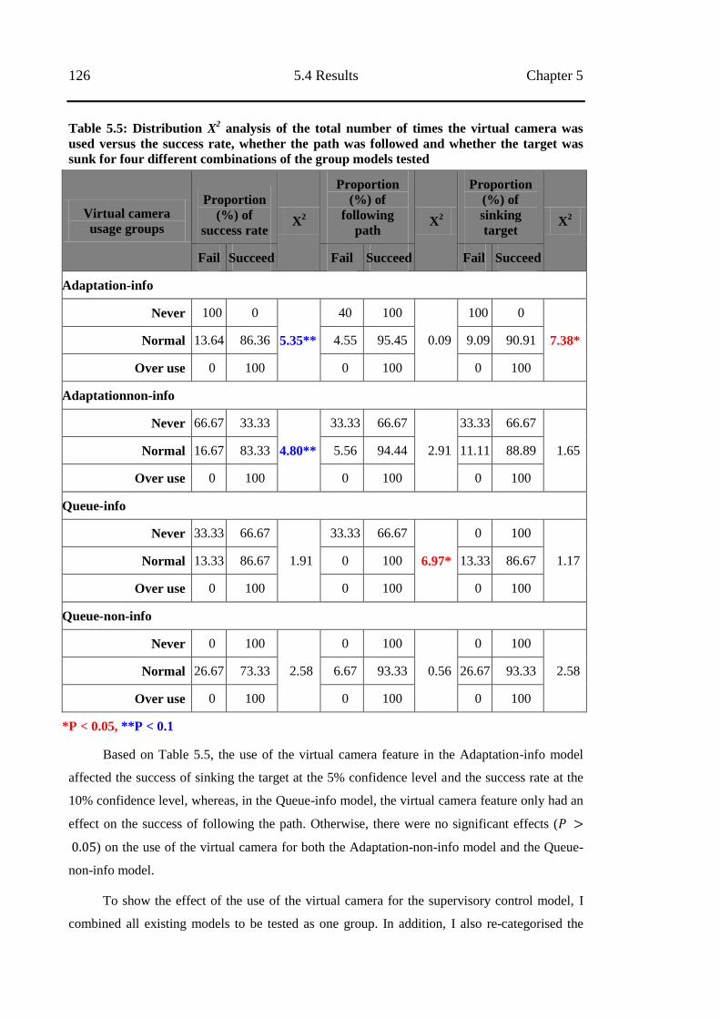
126 5.4 Results Chapter 5
Table 5.5: Distribution X2 analysis of the total number of times the virtual camera was
used versus the success rate, whether the path was followed and whether the target was
sunk for four different combinations of the group models tested
Virtual camera
usage groups
Proportion
(%) of
success rate X
2
Proportion
(%) of
following
path X
2
Proportion
(%) of
sinking
target X
2
Fail Succeed Fail Succeed Fail Succeed
Adaptation-info
Never 100 0
5.35**
40 100
0.09
100 0
7.38* Normal 13.64 86.36 4.55 95.45 9.09 90.91
Over use 0 100 0 100 0 100
Adaptationnon-info
Never 66.67 33.33
4.80**
33.33 66.67
2.91
33.33 66.67
1.65 Normal 16.67 83.33 5.56 94.44 11.11 88.89
Over use 0 100 0 100 0 100
Queue-info
Never 33.33 66.67
1.91
33.33 66.67
6.97*
0 100
1.17 Normal 13.33 86.67 0 100 13.33 86.67
Over use 0 100 0 100 0 100
Queue-non-info
Never 0 100
2.58
0 100
0.56
0 100
2.58 Normal 26.67 73.33 6.67 93.33 26.67 93.33
Over use 0 100 0 100 0 100
*P < 0.05, **P < 0.1
Based on Table 5.5, the use of the virtual camera feature in the Adaptation-info model
affected the success of sinking the target at the 5% confidence level and the success rate at the
10% confidence level, whereas, in the Queue-info model, the virtual camera feature only had an
effect on the success of following the path. Otherwise, there were no significant effects (
) on the use of the virtual camera for both the Adaptation-non-info model and the Queue-
non-info model.
To show the effect of the use of the virtual camera for the supervisory control model, I
combined all existing models to be tested as one group. In addition, I also re-categorised the
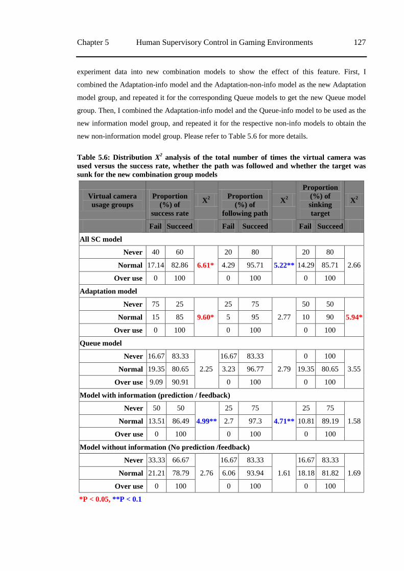
Chapter 5 Human Supervisory Control in Gaming Environments 127
experiment data into new combination models to show the effect of this feature. First, I
combined the Adaptation-info model and the Adaptation-non-info model as the new Adaptation
model group, and repeated it for the corresponding Queue models to get the new Queue model
group. Then, I combined the Adaptation-info model and the Queue-info model to be used as the
new information model group, and repeated it for the respective non-info models to obtain the
new non-information model group. Please refer to Table 5.6 for more details.
Table 5.6: Distribution X2 analysis of the total number of times the virtual camera was
used versus the success rate, whether the path was followed and whether the target was
sunk for the new combination group models
Virtual camera
usage groups
Proportion
(%) of
success rate
X2
Proportion
(%) of
following path
X2
Proportion
(%) of
sinking
target
X2
Fail Succeed Fail Succeed Fail Succeed
All SC model
Never 40 60
6.61*
20 80
5.22**
20 80
2.66 Normal 17.14 82.86 4.29 95.71 14.29 85.71
Over use 0 100 0 100 0 100
Adaptation model
Never 75 25
9.60*
25 75
2.77
50 50
5.94* Normal 15 85 5 95 10 90
Over use 0 100 0 100 0 100
Queue model
Never 16.67 83.33
2.25
16.67 83.33
2.79
0 100
3.55 Normal 19.35 80.65 3.23 96.77 19.35 80.65
Over use 9.09 90.91 0 100 0 100
Model with information (prediction / feedback)
Never 50 50
4.99**
25 75
4.71**
25 75
1.58 Normal 13.51 86.49 2.7 97.3 10.81 89.19
Over use 0 100 0 100 0 100
Model without information (No prediction /feedback)
Never 33.33 66.67
2.76
16.67 83.33
1.61
16.67 83.33
1.69 Normal 21.21 78.79 6.06 93.94 18.18 81.82
Over use 0 100 0 100 0 100
*P < 0.05, **P < 0.1
128 5.5 Discussion Chapter 5
Table 5.6 shows that the overall use of the virtual camera affected the success rate with a
which was less than required for a significance level of 5% (see first three lines of
the table content), and it only had an effect on the success of the following paths with a
significance level of 10%, hence it is only a minor effect. The ―never‖ category of virtual
camera usage showed lower proportions of success in the three variable outcomes compared to
―normal‖ and ―over‖ usage. Moreover, the ―normal‖ category recorded the highest probability
of success in less than 60 seconds (never = 9.38%, normal = 78.13%, and over use 12.5%).
Applying a similar method of analysis, the X2 distribution model for the stop function
feature showed that 83% of the participants used the stop function in at least one of the models
tested, and the logistic regression model showed those who used the stop functions in the model
were 8.4 times more likely to succeed compared with those who did not use these functions
( ). On the contrary, there was no significant relationship between the utilisation of the
stop function and the result of the experiments (fail or succeed) in the Queue model (
). This means that the stop function feature works better for Adaptation models as
compared to Queue models, even though in this experiment design scenario, the stop function
feature did not significantly affect ( ) the success rate, the success of following the path
and the success of sinking the target.
For comparison purposes, all 24 participants performed an additional sub-experiment to
test the direct/manual control model using the same design task and experiment. I measured the
PPV value for this model as 0.70 and its sensitivity value as 0.94. Its F1-score was 0.80, which
was smaller than all the supervisory models tested.
5.4.3 Questionnaire
Most participants agreed that all the supervisory models tested were user friendly (the modus
score for the four models ranging from five to seven) and had good performance (modus score
for the four models ranging from four to six). The Queue model with an extra information
model was the most preferred out of the models tested (Mean score = 4.67, modus ranging from
five to seven). In addition, participants also agreed that the extra information in the model
interface helped them in performing the task.
5.5 Discussion
The experiment was designed to evaluate gaming features in applying HSC to improve human
machine interfaces for a telerobotic scenario. This experiment is focused on two models, the
Adaptation and the Queue models, as a response to series of commands which is part of the
Chapter 5 Human Supervisory Control in Gaming Environments 129
planning process in HSC. In order to evaluate user performance based on key components as
mentioned earlier, these two response model were tested with and without additional virtual
information.
Here, a successful task result was defined as a participant followed the path assigned and
sinking a block into the hole during the time allocated. Based on the result I found there is a
moderately strong correlation between these two user performance variables. By splitting the
range of completion time into three groups (0-60 seconds, >60-120 seconds, and >120-180
seconds) and applying logistic regression, I found that in both the Adaptation and Queue
models, most participants could successfully complete the task (by following the correct arrow
and sinking the block) in less than 120 seconds, with the greatest success recorded for the
Queue model with visual planning information. I noticed participants who took longer than 120
seconds to complete the task have a much lower probability of success compared to those who
completed the task more quickly. So, this means the HSC response model tested with this task
scenario allows the participants to successfully complete the task in a short time periods.
In order to evaluate user performance on Adaptation and Queue response model by using
two recorded variables, success following the path and success to sink the block, an analysis
approach using F1-score was applied. The results showed that user performance for the Queue
model is slightly better than the Adaptation model (higher F1-score). In the Queue model, it
seemed that the participants had more control in their movement planning. They could intervene
by easily altering the path using the stop function. Compared with the Queue
model, participants felt that the stop function was more helpful in the Adaptation model
since each time this model defined a new target position, the robot moved directly to the new
target. In this scenario, the stop function was useful in providing a mechanism for checking or
cancelling the planning process.
My first assumption, that the Adaptation model would have faster performance compared
to the Queue model, was not correct based on the test results (path and sunk true). The average
completion time of the Queue model is lower than the Adaptation model, especially for this
experimental design scenario where the participant was focused on pushing a block along a
path.
In evaluating the effect of available features on the variable outcomes, the use of the
virtual camera for all models showed a significant effect overall for the success rate and success
in following the path. The use of the virtual camera feature significantly affects success in
sinking the blocks in the Adaptation model and success in following the path in the Queue
130 5.5 Discussion Chapter 5
model, especially for model with planning information. The strong effect of the use of the
virtual camera in successfully sinking the target in the Adaptation model was because the
process was similar to direct/manual control. The participant did not need to change viewpoints
when following the path since the model was always responding to each command given. This
feature does not seem to be required in this situation, but worked better to identify where the
block position was located form the target hole. Meanwhile, use of the virtual camera in
following the path in the Queue model seems to work better as after the participants finished
defining the target positions they had more time to observe the model movement when
following the path.
The experimental results showed that there is no strong statistical correlation between the
use of the stop function feature and the success in following the path, or between the use of the
stop function and the success in sinking the block. The results also showed those who used the
stop function were eight times more likely to record success in following the path and in sinking
of the target compared to those who did not use it. Thus, the models tested with visual planning
information performed better than those without it. The planning information is useful in
helping the participants to perform the task, especially for the Queue model. In addition, I
assume the stop function was not widely used since I only tested the system with a low level
HSC design. In a real task scenario, especially in mining telemanipulation, there are a number of
situations which require this function, one of the example is when the robot arm nearly hit the
wall because incorrect command which can possibly damage the robot.
Comparing the performance between the best HSC response model (Queue with info
model) and direct/manual control, participants who used the supervisory model did better in
following the path and sinking the block than those who used direct/manual model. The
movement planning function appeared to be an important feature which should be provided in
telerobotics especially for the supervisory control model.
In addition to the objective measurements collected, I also asked the participants with
several open-ended questions about interface performance. Participants were asked which
features they were most attracted to and their suggestions for improving the interface
performance. Some participants said that the interface was enjoyable and gratify, I therefore
argue that the gaming environment has played a significant role in creating a sense of
immersion contributing to the participants‘ satisfaction. When asked about the features of the
interface, most mentioned that they liked the functionality of the interface in providing
information. As mentioned by one participant, ―The mixture of 3D and video interfaces was
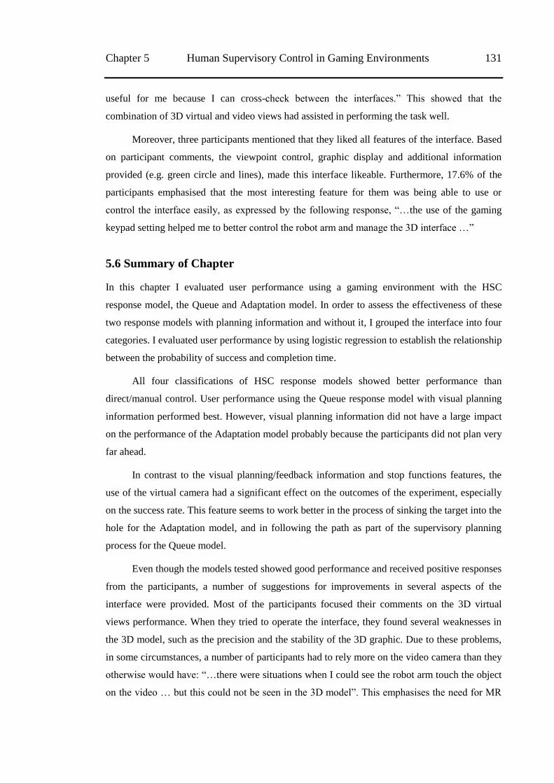
Chapter 5 Human Supervisory Control in Gaming Environments 131
useful for me because I can cross-check between the interfaces.‖ This showed that the
combination of 3D virtual and video views had assisted in performing the task well.
Moreover, three participants mentioned that they liked all features of the interface. Based
on participant comments, the viewpoint control, graphic display and additional information
provided (e.g. green circle and lines), made this interface likeable. Furthermore, 17.6% of the
participants emphasised that the most interesting feature for them was being able to use or
control the interface easily, as expressed by the following response, ―…the use of the gaming
keypad setting helped me to better control the robot arm and manage the 3D interface …‖
5.6 Summary of Chapter
In this chapter I evaluated user performance using a gaming environment with the HSC
response model, the Queue and Adaptation model. In order to assess the effectiveness of these
two response models with planning information and without it, I grouped the interface into four
categories. I evaluated user performance by using logistic regression to establish the relationship
between the probability of success and completion time.
All four classifications of HSC response models showed better performance than
direct/manual control. User performance using the Queue response model with visual planning
information performed best. However, visual planning information did not have a large impact
on the performance of the Adaptation model probably because the participants did not plan very
far ahead.
In contrast to the visual planning/feedback information and stop functions features, the
use of the virtual camera had a significant effect on the outcomes of the experiment, especially
on the success rate. This feature seems to work better in the process of sinking the target into the
hole for the Adaptation model, and in following the path as part of the supervisory planning
process for the Queue model.
Even though the models tested showed good performance and received positive responses
from the participants, a number of suggestions for improvements in several aspects of the
interface were provided. Most of the participants focused their comments on the 3D virtual
views performance. When they tried to operate the interface, they found several weaknesses in
the 3D model, such as the precision and the stability of the 3D graphic. Due to these problems,
in some circumstances, a number of participants had to rely more on the video camera than they
otherwise would have: ―…there were situations when I could see the robot arm touch the object
on the video … but this could not be seen in the 3D model‖. This emphasises the need for MR
132 5.6 Summary of Chapter Chapter 5
in interfaces to provide a mechanism that allows human interpretation to be applied where
inaccurate sensing has introduced model errors.
In this chapter, I have tested the latest prototype of telerobotic interfaces with MR and
HSC concepts applied. As mentioned above, I have only applied low level task HSC for
performing a task in real telerobotic scenarios, thus the latency issue is not perfectly addressed.
Based on the experiment results, the built system successfully performs when used by
participants with a specific background, such as university students. Therefore, there is no
evidence to suggest that the system will be user friendly for everyone. In order to test the user
satisfaction on this telerobotic interfaces, the next chapter will describe an experiment whereby
participants (from diverse background) tested the latest prototype telerobotic interfaces. In the
next chapter, a Weibull distribution is also used to analyse the distribution data of user
performance.
133
Chapter 6
The Utilisation of Weibull Distribution for User
Performance Analysis
This chapter presents the analysis using the Weibull distribution to evaluate the user
performance of the latest prototype telerobotics user interface. I deployed this telerobotic
interfaces for public testing at an exhibition in the CSIRO Discovery Centre, Canberra,
Australia, and conducted the experiment over three months (May to July 2012). I recorded 6139
total user sessions. The Weibull distribution was applied to analyse the reliability of the user
performance data based on two response models, Adaptation and Queue response models. In
addition, I also recorded the user performance for direct/manual control and conducted the same
analysis as a comparison.
6.1 Introduction
Mathematical models are mostly used to explain actual problems for many different
applications. Murthy [103] suggested two approaches to building suitable mathematical models:
a theory-based model (physics-based model) and an empirical model (data-dependent model).
He also mentioned that the theory-based model is an approach built based on theories that are
relevant to the problems, while the empirical model is an approach that used the available data
as the basis for model building without requiring prior understanding of the underlying
mechanism involved.
The empirical approach is commonly used in experimental studies as most experimental
results exhibit a high degree of variability [103]. This experimental data needs to be modelled
with a suitable distribution model, so it can be viewed as observed outcomes of random
variables from the distribution. In this case, a mathematical model is used to evaluate and
compare the user performance data to assess the suitability of the response models as
telerobotics user interfaces. A distribution model is a common way to interpret information in
the evaluation process. When the data is found to follow a similar pattern as represented in a
known distribution model, the data can be summarised easily.
The Weibull distribution is one of many popular distribution models that have been
applied in many fields such as: engineering, material science and finance. The literature on
Weibull distribution is substantial and scattered across many different journals [103]. It is
commonly used distribution in reliability engineering to model time to fail, time to repair and
134 6.2 Prototype Implementation Chapter 6
material strength [104]. This model has been utilised not only to model the reliability of a
product, but also to study other issues in different stages of the product life cycle, including
quality control. Johnson [105] also stated that the Weibull distribution is a distribution that has
been used in many scenarios.
The advantage of the Weibull distribution is it can easily be transformed into different
kinds of distribution behaviours, which makes it very convenient as a lifetime model [105].
Research conducted by Taylor [106] in 1999 utilised the Weibull distribution to model the
requests scenario in his web telerobotic interfaces. In his scenario, the operators may stop for
any one of many reasons and each of these reasons has a probability of occurring at any
particular time. He found that besides describing the model of user‘s request to interfaces, this
Weibull distribution can be used to compare data captured from telerobotic interfaces during
normal use without conducting controlled experiments and is likely to be applicable to other
classes of interfaces.
An experiment with the ―in the wild‖ method, that uses a visitor of the exhibition as the
participant, was applied to gather observation data. This method reduces the bias from
conducting controlled experiments. The variance of the participants can more accurately
represent a cross section of population. Studying user behaviour from this sample of the
population means I can analyse how my telerobotic interface will be used in a more general way
and use this as a basis for developing interfaces for evaluation with skilled operators.
By adopting the approach model applied by Taylor [106], in this chapter, I analyse the
experiment outcomes based on two response models: Adaptation and Queue. Even though these
telerobotic interfaces have different properties from Taylor‘s web telerobotic interfaces, I
successfully tested whether the Weibull distribution is also suitable for modelling and describing
the distribution of user behaviour/performance in my telerobotic interface. Hence, before I
describe the experiment, the results and the analysis, the next section describes the Weibull
parameters which are used for the main analysis.
6.2 Prototype Implementation
It is not uncommon to find varying user behaviour when utilising telerobotic interfaces. In order
to evaluate the effectiveness of the designed telerobotic interface, an experiment was conducted.
The evaluation was focused on the user behaviour using this telerobotic interface with two
different response models for human supervisory control (HSC), the Adaptation and Queue
response models. The data was gathered over a period of three months using this two response
models, which had been applied in previous experiments.
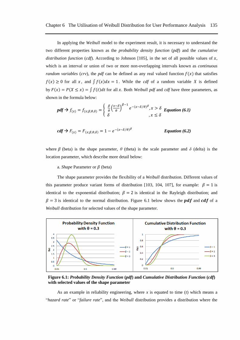
Chapter 6 The Utilisation of Weibull Distribution for User Performance Analysis 135
In applying the Weibull model to the experiment result, it is necessary to understand the
two different properties known as the probability density function (pdf) and the cumulative
distribution function (cdf). According to Johnson [105], in the set of all possible values of ,
which is an interval or union of two or more non-overlapping intervals known as continuous
random variables (crv), the pdf can be defined as any real valued function that satisfies
for all , and ∫ . While the cdf of a random variable X is defined
by ∫ for all . Both Weibull pdf and cdf have three parameters, as
shown in the formula below:
pdf {
(
)
⁄
Equation (6.1)
cdf ⁄ Equation (6.2)
where (beta) is the shape parameter, θ (theta) is the scale parameter and δ (delta) is the
location parameter, which describe more detail below:
a. Shape Parameter or (beta)
The shape parameter provides the flexibility of a Weibull distribution. Different values of
this parameter produce variant forms of distribution [103, 104, 107], for example: is
identical to the exponential distribution; is identical in the Rayleigh distribution; and
is identical to the normal distribution. Figure 6.1 below shows the and of a
Weibull distribution for selected values of the shape parameter.
Figure 6.1: Probability Density Function (pdf) and Cumulative Distribution Function (cdf)
with selected values of the shape parameter
As an example in reliability engineering, where x is equated to time (t) which means a
―hazard rate‖ or ―failure rate‖, and the Weibull distribution provides a distribution where the
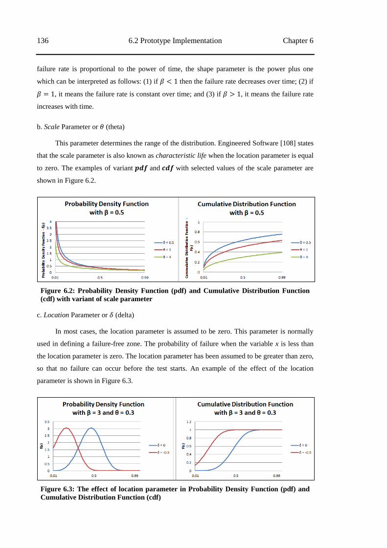
136 6.2 Prototype Implementation Chapter 6
failure rate is proportional to the power of time, the shape parameter is the power plus one
which can be interpreted as follows: (1) if then the failure rate decreases over time; (2) if
, it means the failure rate is constant over time; and (3) if , it means the failure rate
increases with time.
b. Scale Parameter or (theta)
This parameter determines the range of the distribution. Engineered Software [108] states
that the scale parameter is also known as characteristic life when the location parameter is equal
to zero. The examples of variant and with selected values of the scale parameter are
shown in Figure 6.2.
Figure 6.2: Probability Density Function (pdf) and Cumulative Distribution Function
(cdf) with variant of scale parameter
c. Location Parameter or (delta)
In most cases, the location parameter is assumed to be zero. This parameter is normally
used in defining a failure-free zone. The probability of failure when the variable x is less than
the location parameter is zero. The location parameter has been assumed to be greater than zero,
so that no failure can occur before the test starts. An example of the effect of the location
parameter is shown in Figure 6.3.
Figure 6.3: The effect of location parameter in Probability Density Function (pdf) and
Cumulative Distribution Function (cdf)
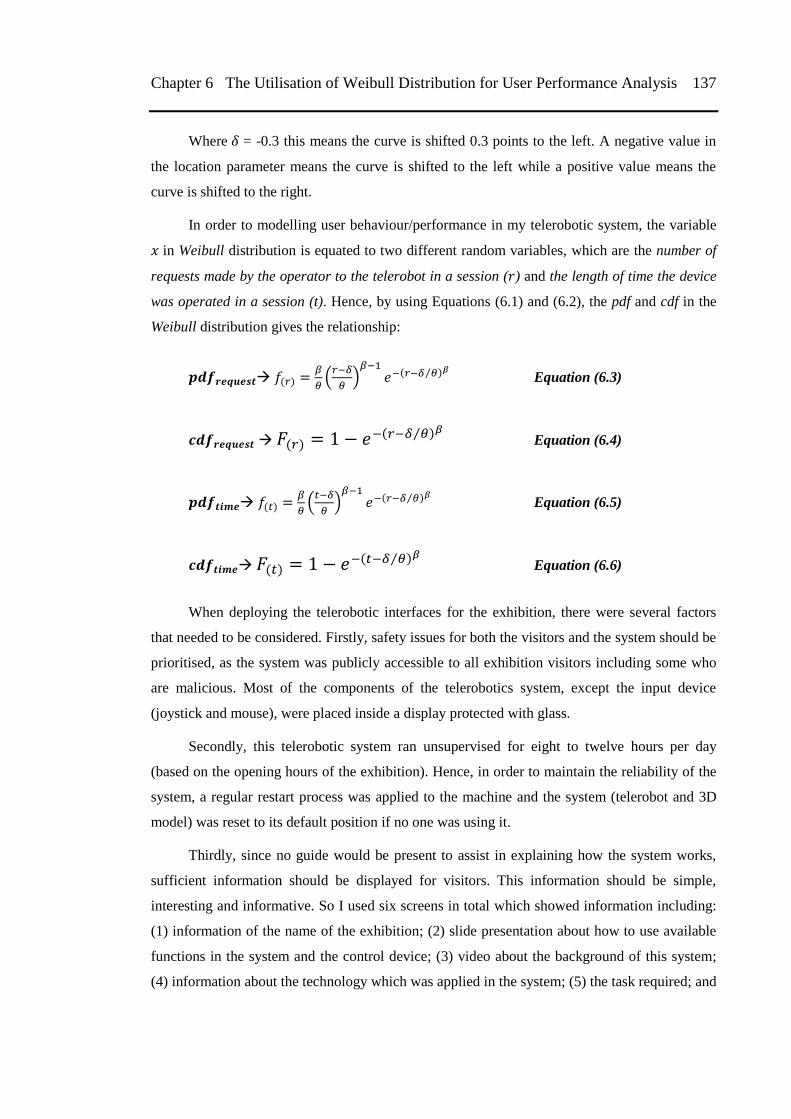
Chapter 6 The Utilisation of Weibull Distribution for User Performance Analysis 137
Where = -0.3 this means the curve is shifted 0.3 points to the left. A negative value in
the location parameter means the curve is shifted to the left while a positive value means the
curve is shifted to the right.
In order to modelling user behaviour/performance in my telerobotic system, the variable
in Weibull distribution is equated to two different random variables, which are the number of
requests made by the operator to the telerobot in a session ( ) and the length of time the device
was operated in a session (t). Hence, by using Equations (6.1) and (6.2), the pdf and cdf in the
Weibull distribution gives the relationship:
(
)
⁄ Equation (6.3)
⁄ Equation (6.4)
(
)
⁄ Equation (6.5)
⁄ Equation (6.6)
When deploying the telerobotic interfaces for the exhibition, there were several factors
that needed to be considered. Firstly, safety issues for both the visitors and the system should be
prioritised, as the system was publicly accessible to all exhibition visitors including some who
are malicious. Most of the components of the telerobotics system, except the input device
(joystick and mouse), were placed inside a display protected with glass.
Secondly, this telerobotic system ran unsupervised for eight to twelve hours per day
(based on the opening hours of the exhibition). Hence, in order to maintain the reliability of the
system, a regular restart process was applied to the machine and the system (telerobot and 3D
model) was reset to its default position if no one was using it.
Thirdly, since no guide would be present to assist in explaining how the system works,
sufficient information should be displayed for visitors. This information should be simple,
interesting and informative. So I used six screens in total which showed information including:
(1) information of the name of the exhibition; (2) slide presentation about how to use available
functions in the system and the control device; (3) video about the background of this system;
(4) information about the technology which was applied in the system; (5) the task required; and
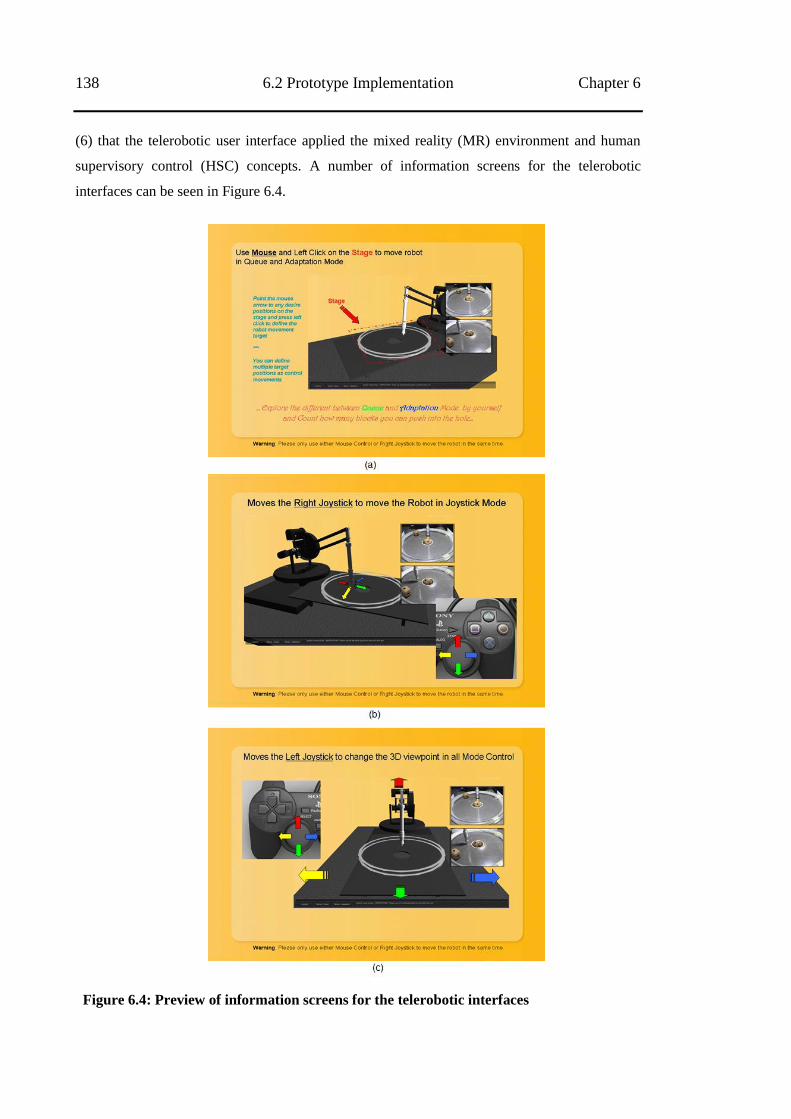
138 6.2 Prototype Implementation Chapter 6
(6) that the telerobotic user interface applied the mixed reality (MR) environment and human
supervisory control (HSC) concepts. A number of information screens for the telerobotic
interfaces can be seen in Figure 6.4.
Figure 6.4: Preview of information screens for the telerobotic interfaces
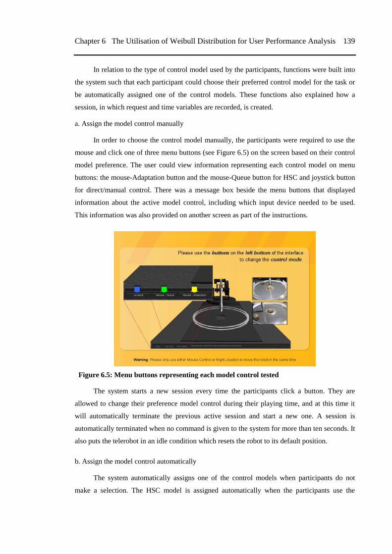
Chapter 6 The Utilisation of Weibull Distribution for User Performance Analysis 139
In relation to the type of control model used by the participants, functions were built into
the system such that each participant could choose their preferred control model for the task or
be automatically assigned one of the control models. These functions also explained how a
session, in which request and time variables are recorded, is created.
a. Assign the model control manually
In order to choose the control model manually, the participants were required to use the
mouse and click one of three menu buttons (see Figure 6.5) on the screen based on their control
model preference. The user could view information representing each control model on menu
buttons: the mouse-Adaptation button and the mouse-Queue button for HSC and joystick button
for direct/manual control. There was a message box beside the menu buttons that displayed
information about the active model control, including which input device needed to be used.
This information was also provided on another screen as part of the instructions.
Figure 6.5: Menu buttons representing each model control tested
The system starts a new session every time the participants click a button. They are
allowed to change their preference model control during their playing time, and at this time it
will automatically terminate the previous active session and start a new one. A session is
automatically terminated when no command is given to the system for more than ten seconds. It
also puts the telerobot in an idle condition which resets the robot to its default position.
b. Assign the model control automatically
The system automatically assigns one of the control models when participants do not
make a selection. The HSC model is assigned automatically when the participants use the
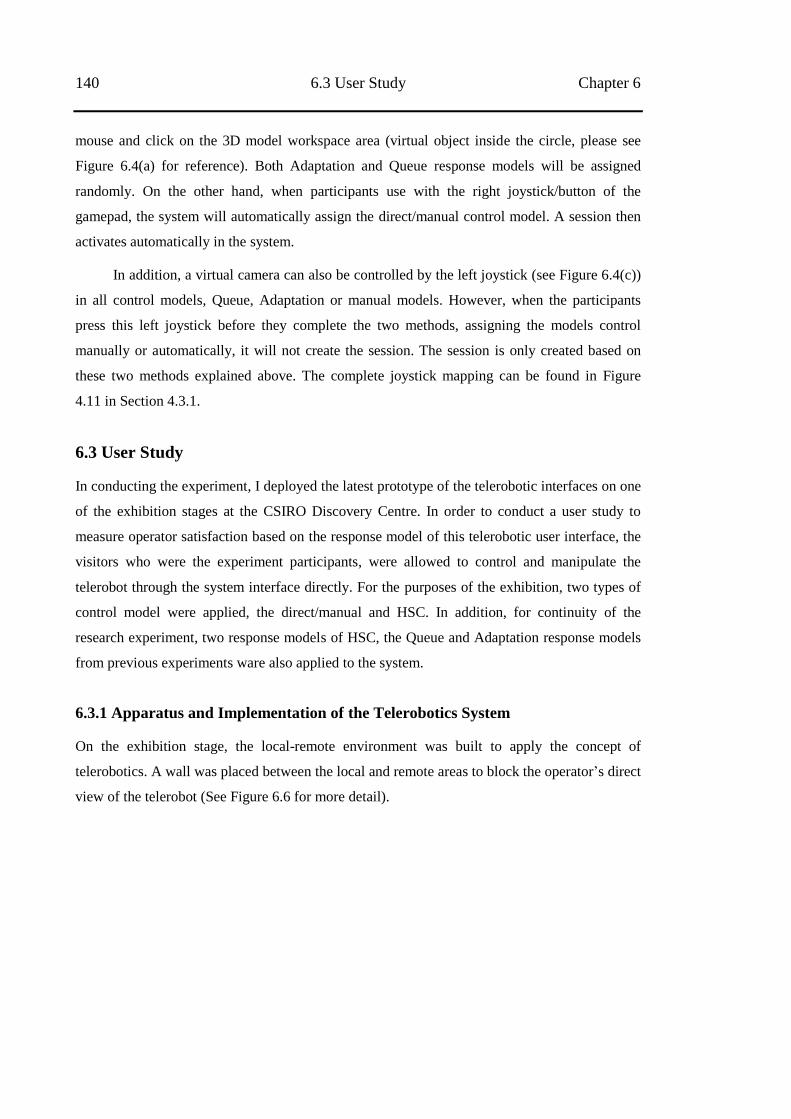
140 6.3 User Study Chapter 6
mouse and click on the 3D model workspace area (virtual object inside the circle, please see
Figure 6.4(a) for reference). Both Adaptation and Queue response models will be assigned
randomly. On the other hand, when participants use with the right joystick/button of the
gamepad, the system will automatically assign the direct/manual control model. A session then
activates automatically in the system.
In addition, a virtual camera can also be controlled by the left joystick (see Figure 6.4(c))
in all control models, Queue, Adaptation or manual models. However, when the participants
press this left joystick before they complete the two methods, assigning the models control
manually or automatically, it will not create the session. The session is only created based on
these two methods explained above. The complete joystick mapping can be found in Figure
4.11 in Section 4.3.1.
6.3 User Study
In conducting the experiment, I deployed the latest prototype of the telerobotic interfaces on one
of the exhibition stages at the CSIRO Discovery Centre. In order to conduct a user study to
measure operator satisfaction based on the response model of this telerobotic user interface, the
visitors who were the experiment participants, were allowed to control and manipulate the
telerobot through the system interface directly. For the purposes of the exhibition, two types of
control model were applied, the direct/manual and HSC. In addition, for continuity of the
research experiment, two response models of HSC, the Queue and Adaptation response models
from previous experiments ware also applied to the system.
6.3.1 Apparatus and Implementation of the Telerobotics System
On the exhibition stage, the local-remote environment was built to apply the concept of
telerobotics. A wall was placed between the local and remote areas to block the operator‘s direct
view of the telerobot (See Figure 6.6 for more detail).
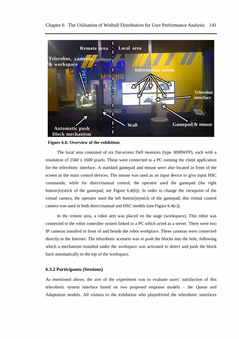
Chapter 6 The Utilisation of Weibull Distribution for User Performance Analysis 141
Figure 6.6: Overview of the exhibition
The local area consisted of six flat-screen Dell monitors (type 3008WFP), each with a
resolution of 2560 x 1600 pixels. These were connected to a PC running the client application
for the telerobotic interface. A standard gamepad and mouse were also located in front of the
screen as the main control devices. The mouse was used as an input device to give input HSC
commands; while for direct/manual control, the operator used the gamepad (the right
button/joystick of the gamepad, see Figure 6.4(b)). In order to change the viewpoint of the
virtual camera, the operator used the left button/joystick of the gamepad; this virtual control
camera was used in both direct/manual and HSC models (see Figure 6.4(c)).
In the remote area, a robot arm was placed on the stage (workspace). This robot was
connected to the robot controller system linked to a PC which acted as a server. There were two
IP cameras installed in front of and beside the robot workplace. These cameras were connected
directly to the Internet. The telerobotic scenario was to push the blocks into the hole, following
which a mechanism installed under the workspace was activated to detect and push the block
back automatically to the top of the workspace.
6.3.2 Participants (Sessions)
As mentioned above, the aim of the experiment was to evaluate users‘ satisfaction of this
telerobotic system interface based on two proposed response models – the Queue and
Adaptation models. All visitors to the exhibition who played/tried the telerobotic interfaces
Wall Gamepad & mouse
Telerobot
interface
Telerobot, cameras,
& workspace
Automatic push
block mechanism
Remote area Local area
Information screen
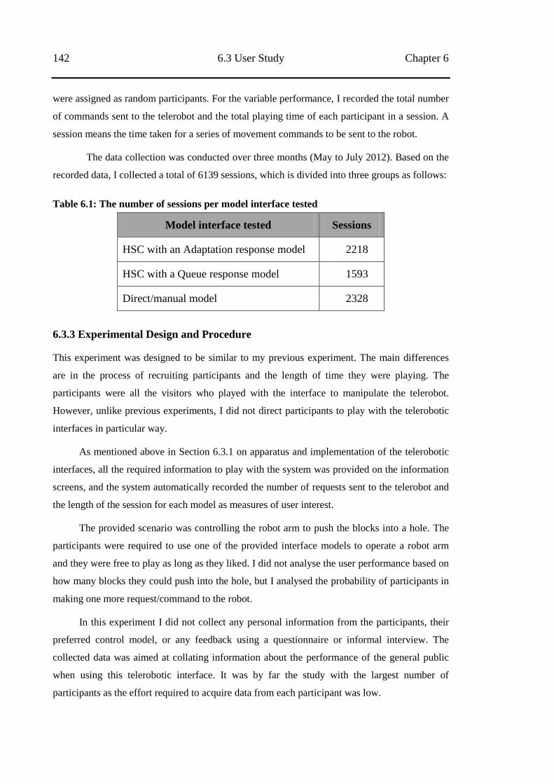
142 6.3 User Study Chapter 6
were assigned as random participants. For the variable performance, I recorded the total number
of commands sent to the telerobot and the total playing time of each participant in a session. A
session means the time taken for a series of movement commands to be sent to the robot.
The data collection was conducted over three months (May to July 2012). Based on the
recorded data, I collected a total of 6139 sessions, which is divided into three groups as follows:
Table 6.1: The number of sessions per model interface tested
Model interface tested Sessions
HSC with an Adaptation response model 2218
HSC with a Queue response model 1593
Direct/manual model 2328
6.3.3 Experimental Design and Procedure
This experiment was designed to be similar to my previous experiment. The main differences
are in the process of recruiting participants and the length of time they were playing. The
participants were all the visitors who played with the interface to manipulate the telerobot.
However, unlike previous experiments, I did not direct participants to play with the telerobotic
interfaces in particular way.
As mentioned above in Section 6.3.1 on apparatus and implementation of the telerobotic
interfaces, all the required information to play with the system was provided on the information
screens, and the system automatically recorded the number of requests sent to the telerobot and
the length of the session for each model as measures of user interest.
The provided scenario was controlling the robot arm to push the blocks into a hole. The
participants were required to use one of the provided interface models to operate a robot arm
and they were free to play as long as they liked. I did not analyse the user performance based on
how many blocks they could push into the hole, but I analysed the probability of participants in
making one more request/command to the robot.
In this experiment I did not collect any personal information from the participants, their
preferred control model, or any feedback using a questionnaire or informal interview. The
collected data was aimed at collating information about the performance of the general public
when using this telerobotic interface. It was by far the study with the largest number of
participants as the effort required to acquire data from each participant was low.
Chapter 6 The Utilisation of Weibull Distribution for User Performance Analysis 143
6.4 Results
I used the Weibull model to fit the experimental result for the total number of requests sent to
the telerobot and the length of time played in a session with the observed data. I
analysed how well the Weibull model could reflect the data or how well the expected
distribution under the model fitted could explain the observed data. In addressing these
questions, I applied two methods by calculating the value of Chi-square goodness fit test
and the Coefficient of Determination from the fitted Weibull curve on the observed
sampling data.
A Chi-square goodness of fit test is normally utilised to test the association between two
variables, the observed and expected variables. Based on Walpole and Myers [109], the Chi-
square goodness fit test can be expressed as:
∑
– Equation (6.7)
where is the value of random data where the sampling distribution has approximated closely
to the Chi-squared distribution with the degree of freedom, v = k – 1. The symbol and
represent the observed and expected variables respectively for each i-th cell with a maximum of
k cells.
Walpole and Myers [109] also mentioned that when the observed data is close to the
corresponding expected data, the value of will be small, indicating that the observed data
model is a good fit for the expected distribution model. On the contrary, when the value of is
large, the fit between the observed and expected data is poor. A good fit leads to the acceptance
of the hypothesis which is indicated by the significant value ( ) not being greater than 0.05
( ). The opposite is indicated by the value of the Chi-squared goodness fit test (
being less than the value of critical value for the significant level of 0.05 (
).
In this case, four variables, which are the random sampling variables (the request ( ) or
the length of playing time ( )) and the three Weibull parameters ( and , are derived from
the Weibull model. The value of the degrees of freedom (v) was obtained by reducing the total
number of cells (k) by 4, v = k – 4. This v value was used to calculate the critical value
mentioned previously.
In terms of decision-making criteria using the Chi-square goodness fit test, Walpole and
Mayer [109] suggested that the value of each expected data should be at least 5. To satisfy this
rule, the adjacent cell where the expected data was less than 5 were combined, and were
144 6.4 Results Chapter 6
assigned as for the request variable and for the time variable. By applying the
Equations (6.3) as and (6.5) as , the satisfaction of all the requirements
above and the Equation (6.7) gives:
∑
( )
– Equation (6.8)
∑
( )
– Equation (6.9)
The Coefficient of Determination is normally used to describe how well the curve of
a statistical model fits with the observed data set. The value of is perceived as a number
between 0 and 1, where a value close to 1 indicates that the curve fits the sampling data set very
well, on the other hand, when the value is close to 0, the curve does not fit the sampling data set.
The use of the value in fitting with various distribution models had been reported by Ricci
[110].
The Coefficient of Determination is the quotient between the total sum of squares
( ) and the regression of squares ( ), where:
∑ Equation (6.10)
∑ Equation (6.11)
the and are the expected and observed data, and is the mean of the observed data,
∑
. Thus, the Coefficient of Determination can be formed as:
∑
∑ Equation (6.12)
The analysis of the two variables, the number of requests and time taken on each model control
tested, are as follows:
6.4.1 HSC with Adaptation Response Model
a. Request variable in Adaptation response model
Based on the observed data set in 2218 sessions for the Adaptation response model,
which was fitted by the Weibull curve, 50.8% of these sessions were unsuccessful in sending
Chapter 6 The Utilisation of Weibull Distribution for User Performance Analysis 145
any requests to the telerobot. This could be due to a number of reasons such as the participants
lost interest or the robot stuck. However, the remaining observed data still showed sufficient
information that could be analysed, where the most number of requests in a single session was
188, and there were 35 sessions with at least 50 requests per session. By excluding the first four
requests from data analysis , I found the Weibull curve fitted the observed data with the
estimated variables:
, where
, where
A plot of the observed and estimated data for the number of requests sent to the telerobot
(1 to 80) using HSC with the Adaptation response model is shown in Figure 6.7.
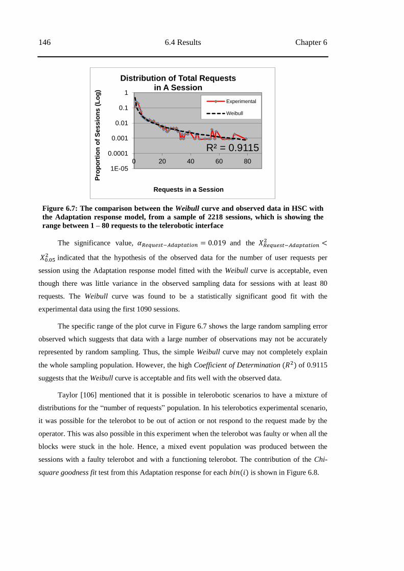
146 6.4 Results Chapter 6
Figure 6.7: The comparison between the Weibull curve and observed data in HSC with
the Adaptation response model, from a sample of 2218 sessions, which is showing the
range between 1 – 80 requests to the telerobotic interface
The significance value, and the
indicated that the hypothesis of the observed data for the number of user requests per
session using the Adaptation response model fitted with the Weibull curve is acceptable, even
though there was little variance in the observed sampling data for sessions with at least 80
requests. The Weibull curve was found to be a statistically significant good fit with the
experimental data using the first 1090 sessions.
The specific range of the plot curve in Figure 6.7 shows the large random sampling error
observed which suggests that data with a large number of observations may not be accurately
represented by random sampling. Thus, the simple Weibull curve may not completely explain
the whole sampling population. However, the high Coefficient of Determination of 0.9115
suggests that the Weibull curve is acceptable and fits well with the observed data.
Taylor [106] mentioned that it is possible in telerobotic scenarios to have a mixture of
distributions for the ―number of requests‖ population. In his telerobotics experimental scenario,
it was possible for the telerobot to be out of action or not respond to the request made by the
operator. This was also possible in this experiment when the telerobot was faulty or when all the
blocks were stuck in the hole. Hence, a mixed event population was produced between the
sessions with a faulty telerobot and with a functioning telerobot. The contribution of the Chi-
square goodness fit test from this Adaptation response for each is shown in Figure 6.8.
R² = 0.9115
1E-05
0.0001
0.001
0.01
0.1
1
0 20 40 60 80
Pro
po
rtio
n o
f S
essio
ns (
Lo
g)
Requests in a Session
Distribution of Total Requests in A Session
Experimental
Weibull
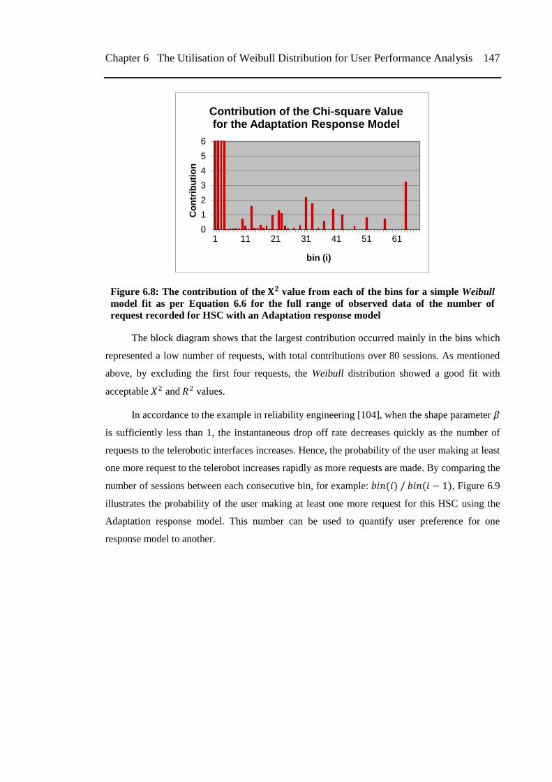
Chapter 6 The Utilisation of Weibull Distribution for User Performance Analysis 147
Figure 6.8: The contribution of the value from each of the bins for a simple Weibull
model fit as per Equation 6.6 for the full range of observed data of the number of
request recorded for HSC with an Adaptation response model
The block diagram shows that the largest contribution occurred mainly in the bins which
represented a low number of requests, with total contributions over 80 sessions. As mentioned
above, by excluding the first four requests, the Weibull distribution showed a good fit with
acceptable and values.
In accordance to the example in reliability engineering [104], when the shape parameter
is sufficiently less than 1, the instantaneous drop off rate decreases quickly as the number of
requests to the telerobotic interfaces increases. Hence, the probability of the user making at least
one more request to the telerobot increases rapidly as more requests are made. By comparing the
number of sessions between each consecutive bin, for example: , Figure 6.9
illustrates the probability of the user making at least one more request for this HSC using the
Adaptation response model. This number can be used to quantify user preference for one
response model to another.
0
1
2
3
4
5
6
1 11 21 31 41 51 61
Co
ntr
ibu
tio
n
bin (i)
Contribution of the Chi-square Value for the Adaptation Response Model
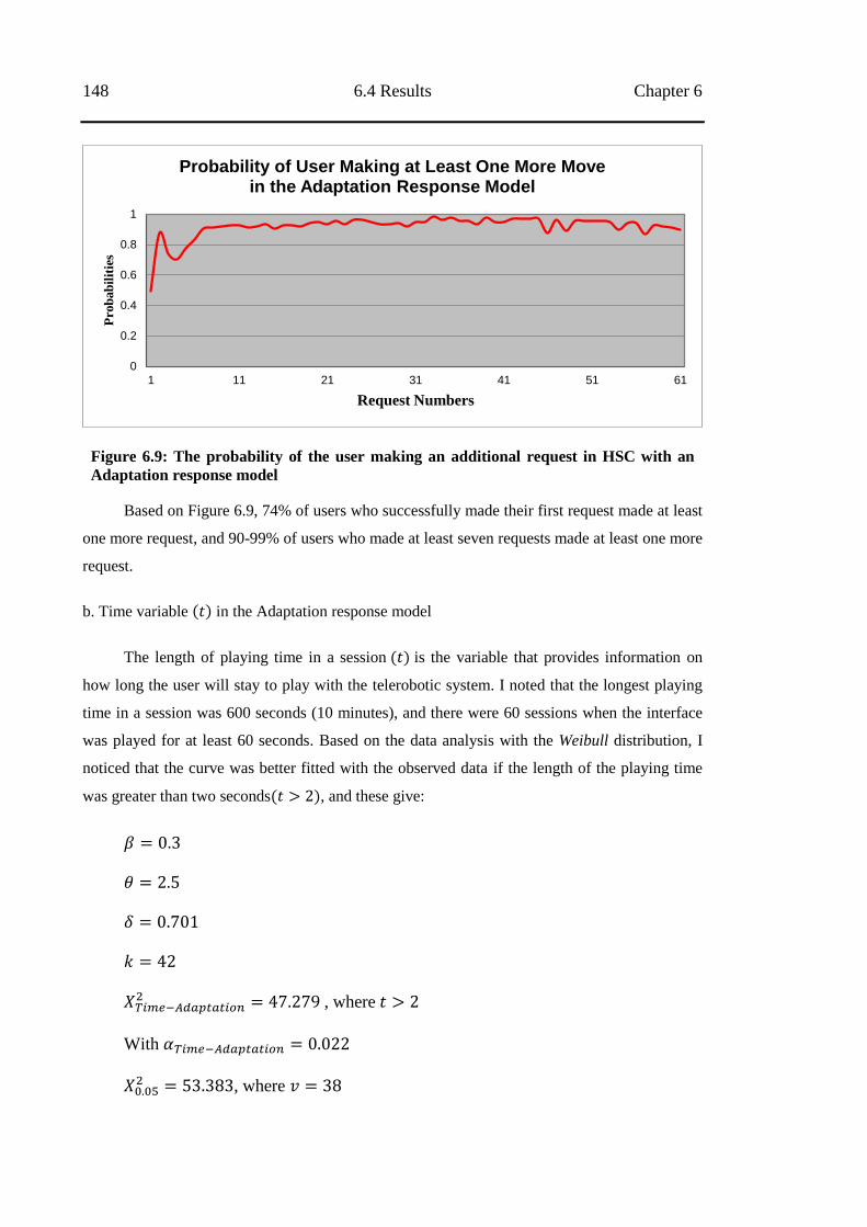
148 6.4 Results Chapter 6
Figure 6.9: The probability of the user making an additional request in HSC with an
Adaptation response model
Based on Figure 6.9, 74% of users who successfully made their first request made at least
one more request, and 90-99% of users who made at least seven requests made at least one more
request.
b. Time variable in the Adaptation response model
The length of playing time in a session is the variable that provides information on
how long the user will stay to play with the telerobotic system. I noted that the longest playing
time in a session was 600 seconds (10 minutes), and there were 60 sessions when the interface
was played for at least 60 seconds. Based on the data analysis with the Weibull distribution, I
noticed that the curve was better fitted with the observed data if the length of the playing time
was greater than two seconds , and these give:
, where
With
, where
0
0.2
0.4
0.6
0.8
1
1 11 21 31 41 51 61
Pro
bab
ilit
ies
Request Numbers
Probability of User Making at Least One More Move in the Adaptation Response Model
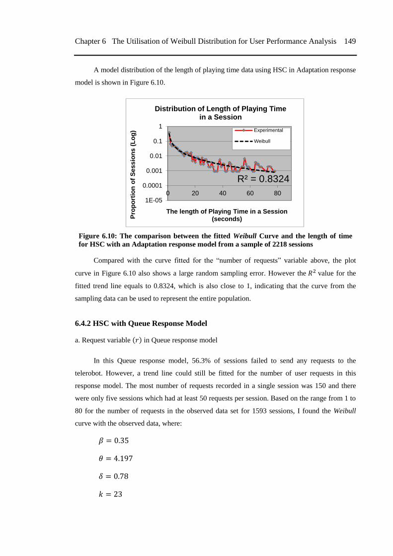
Chapter 6 The Utilisation of Weibull Distribution for User Performance Analysis 149
A model distribution of the length of playing time data using HSC in Adaptation response
model is shown in Figure 6.10.
Figure 6.10: The comparison between the fitted Weibull Curve and the length of time
for HSC with an Adaptation response model from a sample of 2218 sessions
Compared with the curve fitted for the ―number of requests‖ variable above, the plot
curve in Figure 6.10 also shows a large random sampling error. However the value for the
fitted trend line equals to 0.8324, which is also close to 1, indicating that the curve from the
sampling data can be used to represent the entire population.
6.4.2 HSC with Queue Response Model
a. Request variable in Queue response model
In this Queue response model, 56.3% of sessions failed to send any requests to the
telerobot. However, a trend line could still be fitted for the number of user requests in this
response model. The most number of requests recorded in a single session was 150 and there
were only five sessions which had at least 50 requests per session. Based on the range from 1 to
80 for the number of requests in the observed data set for 1593 sessions, I found the Weibull
curve with the observed data, where:
R² = 0.8324
1E-05
0.0001
0.001
0.01
0.1
1
0 20 40 60 80
Pro
po
rtio
n o
f S
es
sio
ns
(L
og
)
The length of Playing Time in a Session (seconds)
Distribution of Length of Playing Time in a Session
Experimental
Weibull
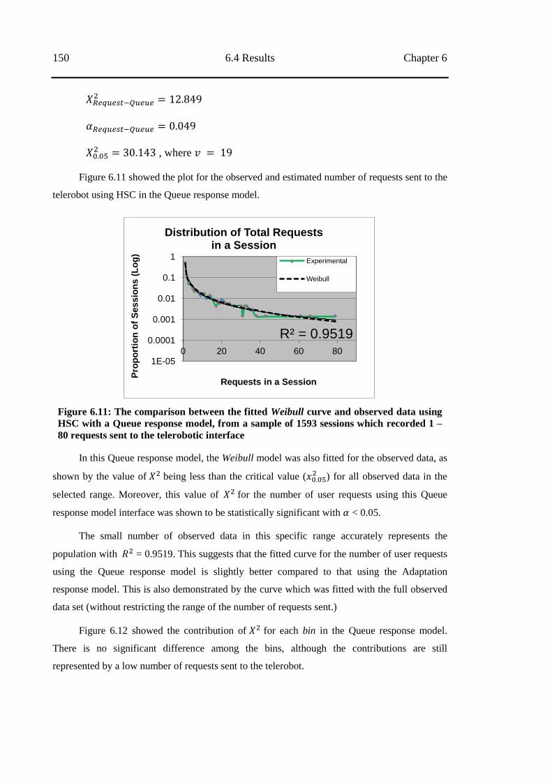
150 6.4 Results Chapter 6
, where
Figure 6.11 showed the plot for the observed and estimated number of requests sent to the
telerobot using HSC in the Queue response model.
Figure 6.11: The comparison between the fitted Weibull curve and observed data using
HSC with a Queue response model, from a sample of 1593 sessions which recorded 1 –
80 requests sent to the telerobotic interface
In this Queue response model, the Weibull model was also fitted for the observed data, as
shown by the value of being less than the critical value ( ) for all observed data in the
selected range. Moreover, this value of for the number of user requests using this Queue
response model interface was shown to be statistically significant with < 0.05.
The small number of observed data in this specific range accurately represents the
population with = 0.9519. This suggests that the fitted curve for the number of user requests
using the Queue response model is slightly better compared to that using the Adaptation
response model. This is also demonstrated by the curve which was fitted with the full observed
data set (without restricting the range of the number of requests sent.)
Figure 6.12 showed the contribution of for each bin in the Queue response model.
There is no significant difference among the bins, although the contributions are still
represented by a low number of requests sent to the telerobot.
R² = 0.9519
1E-05
0.0001
0.001
0.01
0.1
1
0 20 40 60 80
Pro
po
rtio
n o
f S
es
sio
ns
(L
og
)
Requests in a Session
Distribution of Total Requests in a Session
Experimental
Weibull
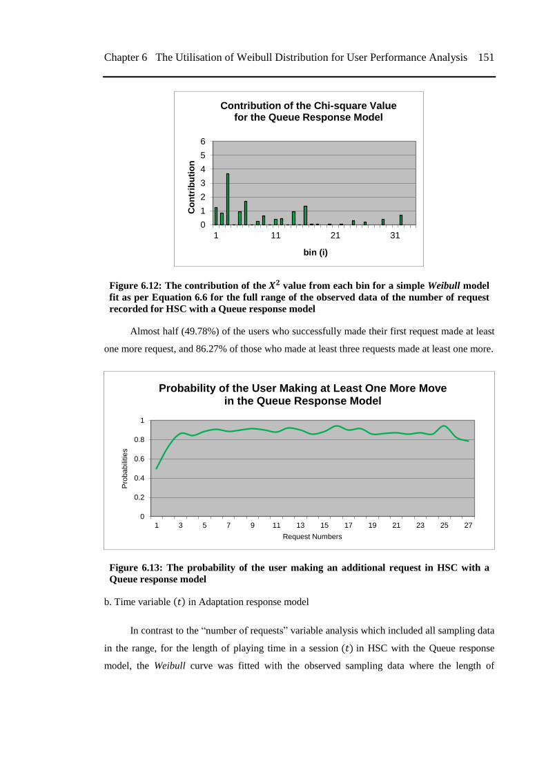
Chapter 6 The Utilisation of Weibull Distribution for User Performance Analysis 151
Figure 6.12: The contribution of the value from each bin for a simple Weibull model
fit as per Equation 6.6 for the full range of the observed data of the number of request
recorded for HSC with a Queue response model
Almost half (49.78%) of the users who successfully made their first request made at least
one more request, and 86.27% of those who made at least three requests made at least one more.
Figure 6.13: The probability of the user making an additional request in HSC with a
Queue response model
b. Time variable in Adaptation response model
In contrast to the ―number of requests‖ variable analysis which included all sampling data
in the range, for the length of playing time in a session in HSC with the Queue response
model, the Weibull curve was fitted with the observed sampling data where the length of
0
1
2
3
4
5
6
1 11 21 31
Co
ntr
ibu
tio
n
bin (i)
Contribution of the Chi-square Value for the Queue Response Model
0
0.2
0.4
0.6
0.8
1
1 3 5 7 9 11 13 15 17 19 21 23 25 27
Pro
babili
tie
s
Request Numbers
Probability of the User Making at Least One More Move in the Queue Response Model
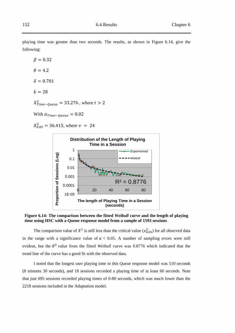
152 6.4 Results Chapter 6
playing time was greater than two seconds. The results, as shown in Figure 6.14, give the
following:
, where
With
, where
Figure 6.14: The comparison between the fitted Weibull curve and the length of playing
time using HSC with a Queue response model from a sample of 1593 sessions
The comparison value of is still less than the critical value ( ) for all observed data
in the range with a significance value of < 0.05. A number of sampling errors were still
evident, but the value from the fitted Weibull curve was 0.8776 which indicated that the
trend line of the curve has a good fit with the observed data.
I noted that the longest user playing time in this Queue response model was 510 seconds
(8 minutes 30 seconds), and 18 sessions recorded a playing time of at least 60 seconds. Note
that just 695 sessions recorded playing times of 0-80 seconds, which was much lower than the
2218 sessions included in the Adaptation model.
R² = 0.8776
1E-05
0.0001
0.001
0.01
0.1
1
0 20 40 60 80
Pro
po
rtio
n o
f S
es
sio
ns
(L
og
)
The length of Playing Time in a Session (seconds)
Distribution of the Length of Playing Time in a Session
Experimental
Weibull
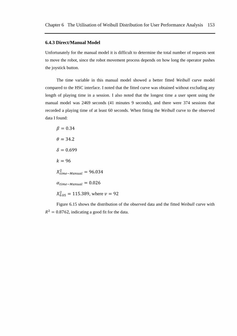
Chapter 6 The Utilisation of Weibull Distribution for User Performance Analysis 153
6.4.3 Direct/Manual Model
Unfortunately for the manual model it is difficult to determine the total number of requests sent
to move the robot, since the robot movement process depends on how long the operator pushes
the joystick button.
The time variable in this manual model showed a better fitted Weibull curve model
compared to the HSC interface. I noted that the fitted curve was obtained without excluding any
length of playing time in a session. I also noted that the longest time a user spent using the
manual model was 2469 seconds (41 minutes 9 seconds), and there were 374 sessions that
recorded a playing time of at least 60 seconds. When fitting the Weibull curve to the observed
data I found:
, where
Figure 6.15 shows the distribution of the observed data and the fitted Weibull curve with
, indicating a good fit for the data.
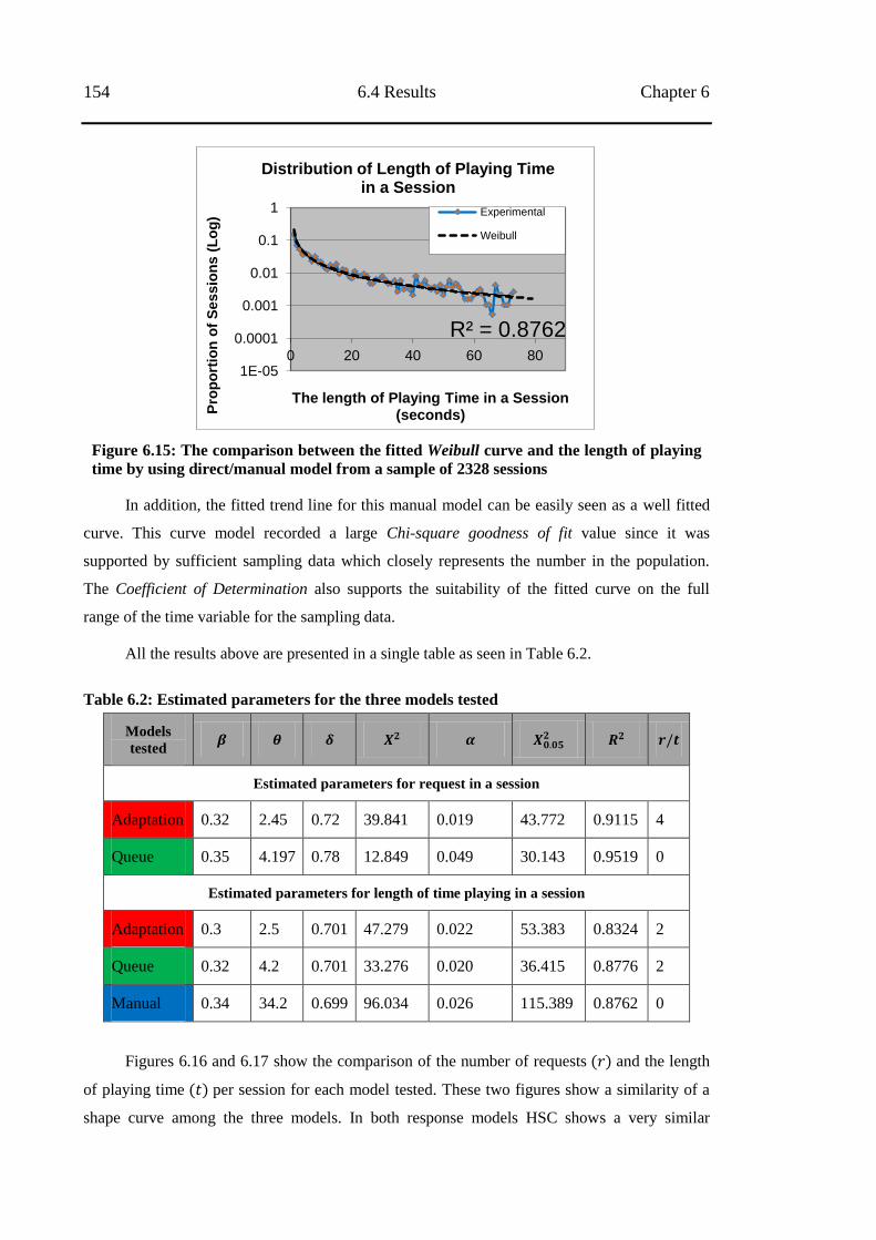
154 6.4 Results Chapter 6
Figure 6.15: The comparison between the fitted Weibull curve and the length of playing
time by using direct/manual model from a sample of 2328 sessions
In addition, the fitted trend line for this manual model can be easily seen as a well fitted
curve. This curve model recorded a large Chi-square goodness of fit value since it was
supported by sufficient sampling data which closely represents the number in the population.
The Coefficient of Determination also supports the suitability of the fitted curve on the full
range of the time variable for the sampling data.
All the results above are presented in a single table as seen in Table 6.2.
Table 6.2: Estimated parameters for the three models tested
Models
tested
Estimated parameters for request in a session
Adaptation 0.32 2.45 0.72 39.841 0.019 43.772 0.9115 4
Queue 0.35 4.197 0.78 12.849 0.049 30.143 0.9519 0
Estimated parameters for length of time playing in a session
Adaptation 0.3 2.5 0.701 47.279 0.022 53.383 0.8324 2
Queue 0.32 4.2 0.701 33.276 0.020 36.415 0.8776 2
Manual 0.34 34.2 0.699 96.034 0.026 115.389 0.8762 0
Figures 6.16 and 6.17 show the comparison of the number of requests and the length
of playing time per session for each model tested. These two figures show a similarity of a
shape curve among the three models. In both response models HSC shows a very similar
R² = 0.8762
1E-05
0.0001
0.001
0.01
0.1
1
0 20 40 60 80
Pro
po
rtio
n o
f S
es
sio
ns
(L
og
)
The length of Playing Time in a Session (seconds)
Distribution of Length of Playing Time in a Session
Experimental
Weibull
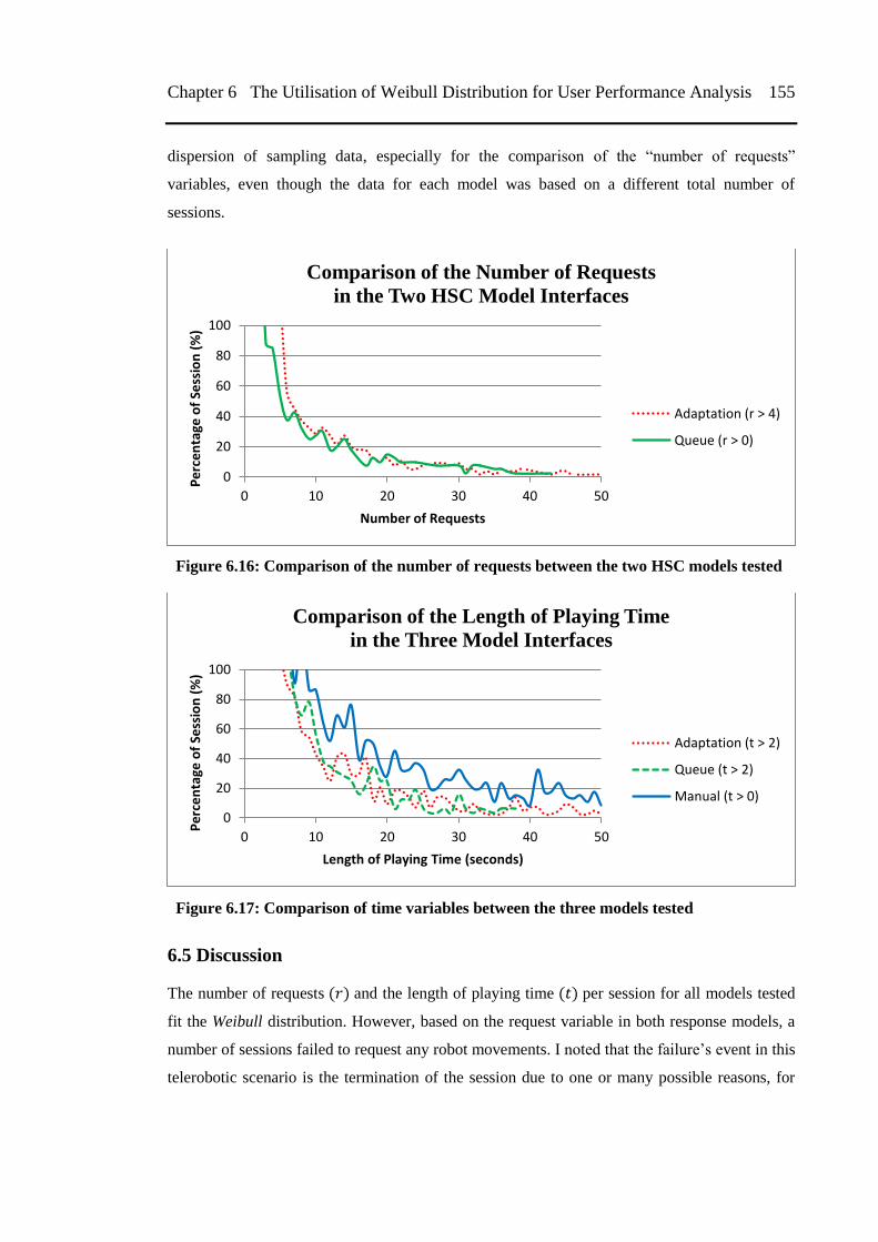
Chapter 6 The Utilisation of Weibull Distribution for User Performance Analysis 155
dispersion of sampling data, especially for the comparison of the ―number of requests‖
variables, even though the data for each model was based on a different total number of
sessions.
Figure 6.16: Comparison of the number of requests between the two HSC models tested
Figure 6.17: Comparison of time variables between the three models tested
6.5 Discussion
The number of requests and the length of playing time per session for all models tested
fit the Weibull distribution. However, based on the request variable in both response models, a
number of sessions failed to request any robot movements. I noted that the failure‘s event in this
telerobotic scenario is the termination of the session due to one or many possible reasons, for
0
20
40
60
80
100
0 10 20 30 40 50
Pe
rce
nta
ge o
f Se
ssio
n (
%)
Number of Requests
Comparison of the Number of Requests
in the Two HSC Model Interfaces
Adaptation (r > 4)
Queue (r > 0)
0
20
40
60
80
100
0 10 20 30 40 50
Pe
rce
nta
ge o
f Se
ssio
n (
%)
Length of Playing Time (seconds)
Comparison of the Length of Playing Time
in the Three Model Interfaces
Adaptation (t > 2)
Queue (t > 2)
Manual (t > 0)
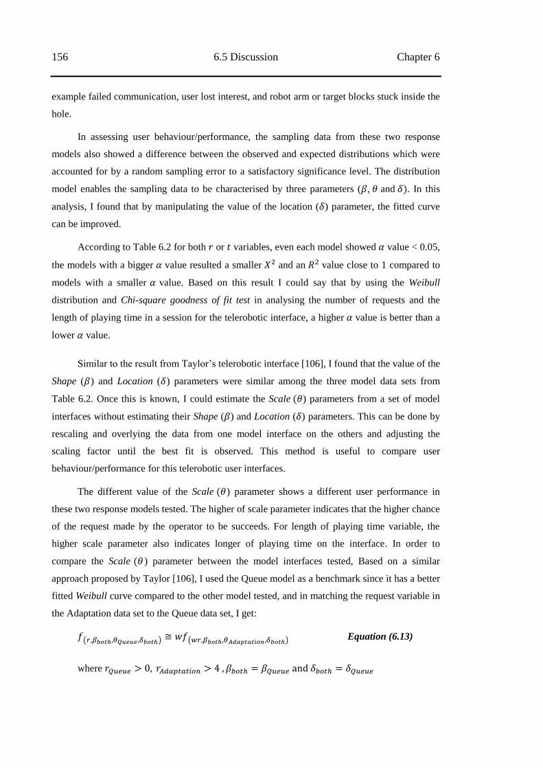
156 6.5 Discussion Chapter 6
example failed communication, user lost interest, and robot arm or target blocks stuck inside the
hole.
In assessing user behaviour/performance, the sampling data from these two response
models also showed a difference between the observed and expected distributions which were
accounted for by a random sampling error to a satisfactory significance level. The distribution
model enables the sampling data to be characterised by three parameters ( , and . In this
analysis, I found that by manipulating the value of the location ( ) parameter, the fitted curve
can be improved.
According to Table 6.2 for both or variables, even each model showed value < 0.05,
the models with a bigger value resulted a smaller and an value close to 1 compared to
models with a smaller value. Based on this result I could say that by using the Weibull
distribution and Chi-square goodness of fit test in analysing the number of requests and the
length of playing time in a session for the telerobotic interface, a higher value is better than a
lower value.
Similar to the result from Taylor‘s telerobotic interface [106], I found that the value of the
Shape ( ) and Location ( ) parameters were similar among the three model data sets from
Table 6.2. Once this is known, I could estimate the Scale ) parameters from a set of model
interfaces without estimating their Shape ( ) and Location ( ) parameters. This can be done by
rescaling and overlying the data from one model interface on the others and adjusting the
scaling factor until the best fit is observed. This method is useful to compare user
behaviour/performance for this telerobotic user interfaces.
The different value of the Scale ) parameter shows a different user performance in
these two response models tested. The higher of scale parameter indicates that the higher chance
of the request made by the operator to be succeeds. For length of playing time variable, the
higher scale parameter also indicates longer of playing time on the interface. In order to
compare the Scale ) parameter between the model interfaces tested, Based on a similar
approach proposed by Taylor [106], I used the Queue model as a benchmark since it has a better
fitted Weibull curve compared to the other model tested, and in matching the request variable in
the Adaptation data set to the Queue data set, I get:
( ) ( )
Equation (6.13)
where
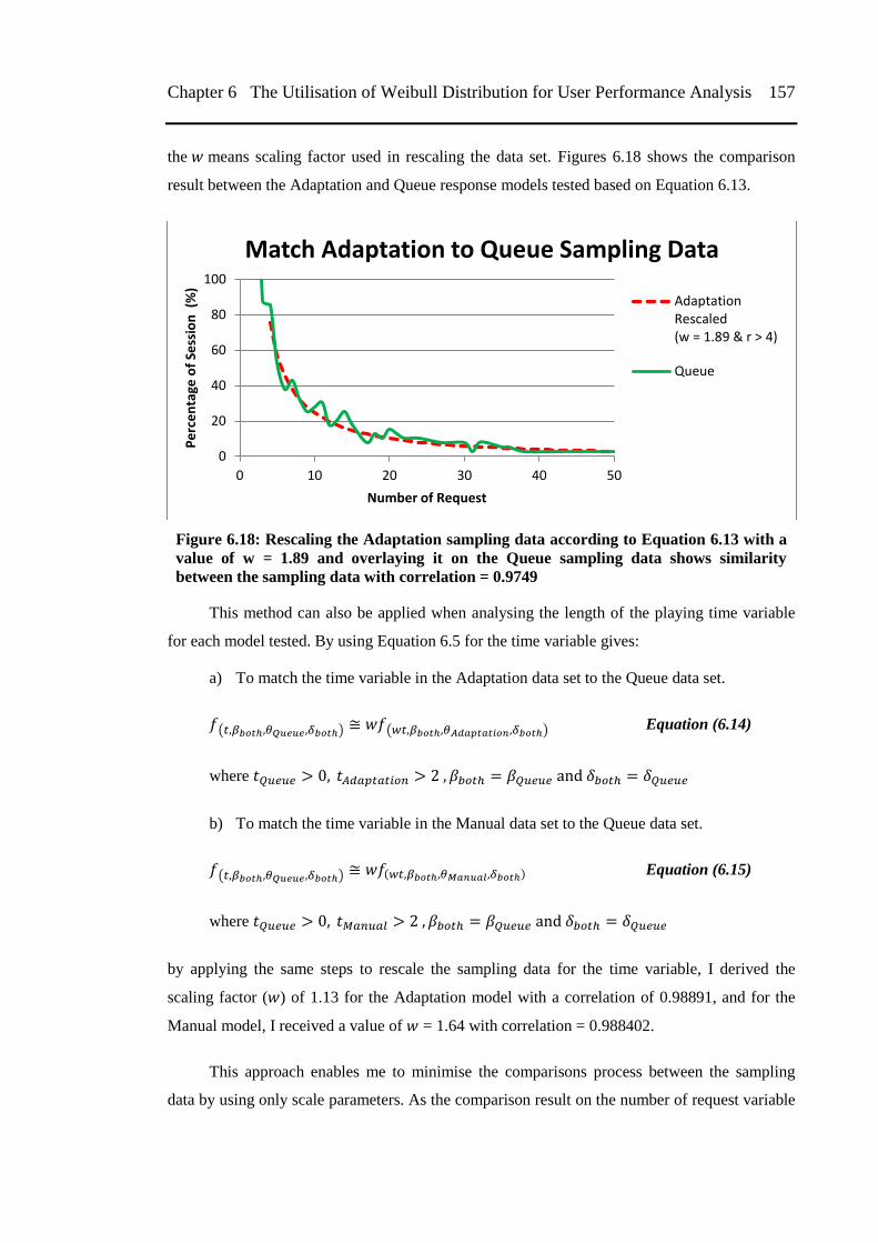
Chapter 6 The Utilisation of Weibull Distribution for User Performance Analysis 157
the means scaling factor used in rescaling the data set. Figures 6.18 shows the comparison
result between the Adaptation and Queue response models tested based on Equation 6.13.
Figure 6.18: Rescaling the Adaptation sampling data according to Equation 6.13 with a
value of w = 1.89 and overlaying it on the Queue sampling data shows similarity
between the sampling data with correlation = 0.9749
This method can also be applied when analysing the length of the playing time variable
for each model tested. By using Equation 6.5 for the time variable gives:
a) To match the time variable in the Adaptation data set to the Queue data set.
( ) ( )
Equation (6.14)
where
b) To match the time variable in the Manual data set to the Queue data set.
( ) Equation (6.15)
where
by applying the same steps to rescale the sampling data for the time variable, I derived the
scaling factor ( ) of 1.13 for the Adaptation model with a correlation of 0.98891, and for the
Manual model, I received a value of = 1.64 with correlation = 0.988402.
This approach enables me to minimise the comparisons process between the sampling
data by using only scale parameters. As the comparison result on the number of request variable
0
20
40
60
80
100
0 10 20 30 40 50
Pe
rce
nta
ge o
f Se
ssio
n (
%)
Number of Request
Match Adaptation to Queue Sampling Data
AdaptationRescaled(w = 1.89 & r > 4)
Queue
158 6.5 Discussion Chapter 6
from the two HSC response model, the Queue response model is preferable compared to the
Adaptation response model. It also showed the same result in the comparison between lengths
of playing time variable from this two HSC response models. In the end, these comparisons
showed operators preferred the Queue response model over the Adaptation response model and
the HSC model over the direct/manual model.
In addition, Table 6.2 showed the Queue response model has a 40% higher Scale
parameter value on both variables tested compared to the Adaptation response model. Since
both or variables in both response models tested have a similar scale ratio, I considered that
the distribution data on the number of requests made by the operator can be used to estimate the
trend curve on how long the operator used the interface and vice versa. The scale ratio also does
not change when I stretched or shrunk the x-axis of r or t variables.
I successfully followed the technique developed by Taylor [106], and found this
technique was applicable to my telerobotic interface, which is very different teleroboics
scenario than was tested by Taylor. The technique used for choosing the scaling factor was
arbitrary as requires choosing a shape parameter for each data set and then estimating a scale
parameter from that. In this technique approach, if the two data sets are compared directly, there
is no need to estimate Shape ( ) and Location ( ) parameters, but there is an assumption it is
the same. The comparison can be done by rescaling and overlaying one data set on the other and
adjusting the scaling factor until the best fit is observed. This telerobotic interface and situation
were quite different to those tested by Taylor and I provided evidence that human response to a
wide variety of interfaces can be characterised by a Weibull distribution.
Walpole [109] stated that the correlation coefficient is a number which attempts to
measure the strength of the relationship between two variables. In this case, the correlation
coefficient is used to determine the relationship between the sampling data and the estimated
scaling factor ( ). Here, the random error from the sampling data was measured in comparison
with the Weibull curve benchmark, and to satisfy the assumption that the test model has the
same Shape ( ) and Location ( ) parameters. A correlation that is close to 1 indicates a strong
relationship between the scaling factor and the sampling data, while a value that is less than 0.5
implies no relationship between the variables.
In this experiment, the total number of sessions in the sample data did not have a large
impact on the distribution of the curve shape. The variance of the random error variables from
the sampling data is negligible as proven by the value of the Chi-square goodness fit test and the
Coefficient of Determination from the Weibull model. However, to achieve a good fit for the
Weibull curve on the ‗number of requests‘ variable for the Adaptation response model (HSC)
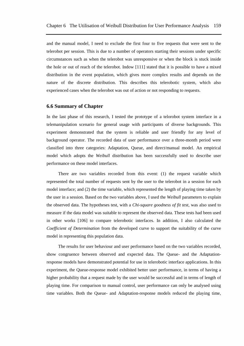
Chapter 6 The Utilisation of Weibull Distribution for User Performance Analysis 159
and the manual model, I need to exclude the first four to five requests that were sent to the
telerobot per session. This is due to a number of operators starting their sessions under specific
circumstances such as when the telerobot was unresponsive or when the block is stuck inside
the hole or out of reach of the telerobot. Indow [111] stated that it is possible to have a mixed
distribution in the event population, which gives more complex results and depends on the
nature of the discrete distribution. This describes this telerobotic system, which also
experienced cases when the telerobot was out of action or not responding to requests.
6.6 Summary of Chapter
In the last phase of this research, I tested the prototype of a telorobot system interface in a
telemanipulation scenario for general usage with participants of diverse backgrounds. This
experiment demonstrated that the system is reliable and user friendly for any level of
background operator. The recorded data of user performance over a three-month period were
classified into three categories: Adaptation, Queue, and direct/manual model. An empirical
model which adopts the Weibull distribution has been successfully used to describe user
performance on these model interfaces.
There are two variables recorded from this event: (1) the request variable which
represented the total number of requests sent by the user to the telerobot in a session for each
model interface; and (2) the time variable, which represented the length of playing time taken by
the user in a session. Based on the two variables above, I used the Weibull parameters to explain
the observed data. The hypotheses test, with a Chi-square goodness of fit test, was also used to
measure if the data model was suitable to represent the observed data. These tests had been used
in other works [106] to compare telerobotic interfaces. In addition, I also calculated the
Coefficient of Determination from the developed curve to support the suitability of the curve
model in representing this population data.
The results for user behaviour and user performance based on the two variables recorded,
show congruence between observed and expected data. The Queue- and the Adaptation-
response models have demonstrated potential for use in telerobotic interface applications. In this
experiment, the Queue-response model exhibited better user performance, in terms of having a
higher probability that a request made by the user would be successful and in terms of length of
playing time. For comparison to manual control, user performance can only be analysed using
time variables. Both the Queue- and Adaptation-response models reduced the playing time,
160 6.6 Summary of Chapter Chapter 6
compared to the manual model. However, this comparison does not prove the manual model
yields superior user performance as it relies on different input devices (joystick and gamepad).
In this analysis, the value of the shape and location parameters proved similar among the
sampling data for each interface tested. Following the approach applied by Taylor [106], I used
only a scale parameter for comparing the sample data of different models, although my
telerobotic interfaces, have very different scenarios compared with Taylor‘s. This technique is
likely to be applicable to other models for interfaces with different properties.
In general, this chapter has supported the idea that applying MR and HSC concepts in
gaming environments for use as telerobotic interface is effective. The next chapter will
summarize my work, including the results and limitations I have identified
161
Chapter 7
Conclusions and Recommendations for Future
Work
7.1 Conclusions
This thesis demonstrated that gaming environments are potentially useful platforms in
evaluating the effectiveness of the concepts of mixed reality (MR) and human supervisory
control (HSC) for telerobotic interfaces.
In this thesis, I categorised the research framework into three main areas: the gaming
environments, the MR interfaces, and HSC. I completed four experiments, which covered the
three categories of the research framework above, to evaluate user performance and
effectiveness of various telerobotic interfaces, which has been published in a number of
international conferences and a Journal as mentioned in the Declaration section, (e.g. APCHI-
2010, ICRA2011, WMC2011, ICIRA2012 and an Australian Journal of Intelligent Information
Processing Systems).
This research addresses a number of gaps in existing research in telerobotics [5, 6], using
a simulated mining scenario. These gaps include: (1) Whether multiple sources of information
increase an operator‘s cognitive fatigue and their level of attention to the interface, leading to
performance reduction; (2) how to improve the effectiveness and user friendliness of telerobotic
interfaces; and (3) how to reduce safety concerns associated with unintended actions and
implicitly remove, or at least decrease, the decline in operator performance caused by latency in
telerobotic scenarios.
Starting from the idea that telerobotic interfaces and gaming environments are similar
domains, would allow us to use sophisticated gaming environments for building telerobotic
interfaces. Although they have been seen as unrelated, I successfully evaluated a number of
features in gaming environments that are required for a telerobotic interface. These include: (1)
the ability to build client-server communications to transfer information between the operator
and the telerobot; (2) the sophistication of the gaming environment in manipulating a 3D model
and a virtual environment for applying MR and HSC to the interface; and (3) other features that
are necessary and useful for telerobotic interfaces, such as suitable input devices and sensors,
additional virtual information and camera views, and path-finding algorithms to improve
telerobot automation. I have shown these gaming features prove useful for telerobotic interface
162 7.1 Conclusions Chapter 7
design. This enables telerobotic interfaces to be developed from powerful existing tools rather
than being developed as bespoke designs.
Virtual-reality software or traditional 3D simulation tools (e.g., WorldToolKit and
VRML) have been used to develop telerobotic interfaces. . Gaming environments offer a
superset of the functionality of these tools but being more specific are less flexible. They have
also become widespread and are now powerful enough to serve as telerobotic interfaces. For
example, from the developer perspective: (1) gaming environments offer an integrated
development environment with a range of predefined and customized software libraries and
functions which are easy to implement; (2) gaming environments provide integrated and
powerful tools in building 3D virtual modelling; (3) gaming environments provide the
technologies for communications and data transfer inside and outside of the gaming
environments; and (4) gaming environments simplify the integration of a variety of input
devices and external sensors.
From the user‘s perspective: (1) gaming environments provide an interface that is easy to
learn and understand, and is user friendly; (2) gaming environments are designed to make
people feel comfortable while used over long periods; and (3) gaming environments have a
primary aim of achieving user immersion, which is an also an important factor for effective
telerobotics interfaces. Gaming environments are thus seen as a suitable platform for applying
and evaluating MR and HSC in telerobotic scenarios.
In order to demonstrate the predominance of gaming environments for telerobotics
scenario, I conducted the first experiment to test the effectiveness of user performance in using
MR interfaces in gaming environments. The combination of overlaying video with a virtual
model in the gaming environments showed that MR interface was able to provide sufficient
information to the operator to perform the experimental tasks. When incomplete information
from the remote environment was provided to the operator in this experiment, they were still
able to access the missing virtual information from overlaid video. This showed that the concept
of combining information by overlaying virtual information on the streaming video, works well
in substituting the missing information. This result explains that when the minimum information
required by the operator is fulfilled; the operation task is possible to be completed. This
technology might be useful to improve operator performance in telerobotic for mining scenarios
or other telerobot scenarios, where there are variance conditions found in remote workspace.
In addition, in this first experiment, I also assessed the effect of the level of user attention
on the interface while performing the task. As the assessment result, the usage of a combination
of information on a single screen did not show any indications of distraction for user
Chapter 7 Conclusions and Recommendations for Future Work 163
performance. Thus, based on the experiment, I can conclude that MR concept for telerobotic
interfaces cause no, or minimal, distraction to the operator.
I designated the ‗mouse‘ as the main input device for delivering commands from the
operator to the interface since it is very commonly used by computer users and computer-based
games. Besides, I chose this input device in order to be used as a main input device for applying
HSC concept for the following experiments. In this first experiment, I tested the use of clicking
and dragging functions of the mouse as input commands, and concluded that the clicking
command was preferred over the dragging command. This is perhaps due to the clicking
command being simpler and is effortless compared to the dragging command.
If it was possible to accurately model a physical environment, videos would not convey
extra information to the operator. In this case it was possible to improve the model in the
gaming environment by applying additional sensors to detect the block/rock position. In order to
investigate whether virtual information is sufficient in providing minimum information required
by the operator to perform the task, I tested a virtual reality interface with enhanced virtual
information for the second experiment. In this experiment, I also tested a potential of gaming
features in term of ease of integration between gaming interfaces and a variety of input devices.
In actualising the investigation of this gaming features, I used an experimental design and
scenario from a previous experiment by Zhu et al [39], that only utilises streaming video for
operator feedback. Corresponding to their experimental design, my experiment utilises a
gamepad and eye-tracking devices to control the virtual camera view to assess user performance
in gaming environment.
The experimental result for the second experiment showed that the gaming environment
is suitable for applying two input devices for virtual camera control in a telerobotic scenario.
Comparable results of user performance indicators derived from two input devices showed
similar performance of participants in completing the task. The trend of user performance on
three sequential operation periods also shows gradual improvement, which indicates that this
gaming environment is an easy learning environment and capable of being understood within a
short period of time. These results strengthened my argument about how gaming environment
and telerobotic interfaces share many similarities and therefore make it possible for them to be
regarded as being in the same domain.
Further experiment in this research, third experiment, I reported the use of the HSC
concept as an alternative to direct/manual control. I applied the principle of HSC into the MR
telerobotic interfaces. The planning process in HSC allowed the operator to define a series of
164 7.1 Conclusions Chapter 7
target positions as input commands to the telerobotic interface. The process gives two models in
response to the operator‘s commands, which I modelled as the Adaptation and Queue response
models. I applied these two HSC response models for the third experiment and compared user
performance operating a robot arm with these two response models. I also applied virtual
objects as additional predictive information to compare the user performance in these two HSC
response models. I tested four different models (Adaptation with predictive information,
Adaptation no-predictive information, Queue with predictive information, and Queue no-
predictive information). In addition, I also tested the direct/manual control as a sub experiment.
I found that user performance in the Queue response model with predictive information
performed best in terms of task completion compared to the other three models. When
compared with the direct/manual control model, the user performance for HSC (both the Queue
and Adaptation response models) was improved.
In this third experiment, I was also concerned about the effect of the use of virtual camera
control and stop functions on user performance. Hence, I conducted analysis on performance of
both functions in relation to the success rate. By categorising the usage of virtual viewpoint
camera control function into three groups (never, normal, and over use), I found that this
function affected user performance in completing the task. This was statistically significant,
especially for the Adaptation response model with predictive information. In general, this
function also affected all response models with predictive information. In contrast with virtual
viewpoint control, I did not find a statistically significant relationship between the use of the
stop function and the success rate for all HSC models tested. This might be due to the
experiment only testing low level HSC commands rather than more sophisticated commands
like ―remove that block to here‖. Although I realised that the stop function was important in
emergency situations or when operator involvement was required, this experiment was not able
to prove conclusively the need for it in the scenario tested.
In the Human Supervisory Control (HSC) model, the operator is not required to
continually control each movement. This means instability, the major problem caused by
latency does not occur. With HSC latency slows the rate an operator can issue commands as it
increases the time they must wait for feedback from previous commands but it does not affect
their ability to carry out the task. For this reason latency is less of an issue in telerobotic
interfaces that make use of the Human Supervisory Control (HSC) model and is why
experiments were not conducted with variable latency. In the open ended questionnaire
responses a few participants commented on latency issues in completing the experimental task.
The combination of MR and HSC in creating predictive information seemed sufficient to divert
Chapter 7 Conclusions and Recommendations for Future Work 165
most participants‘ attention from the effects of latency. This result conforms to the arguments
from a number of other researchers [37 , 74, 75].
As mentioned earlier, it is not possible for me to test my telerobotic interfaces in actual
mining situations, due to access restrictions, time limitations and the inevitability of disrupting
production. Hence, in the first three experiments, I conducted the experiments with volunteers
who had known demographics, as operators. In my last experiment, fourth experiment, I had a
large number of novice users who were visiting the exhibition, of unknown demographics. I
deployed a simulation of a mining telemanipulation scenario in this exhibition for a period of
three months, and recorded the endeavours of exhibition visitors playing with a robot arm. The
goal is to push blocks into a hole by using one of the two HSC response models or
direct/manual model. As the public users were generally novice operators, if the prototype
telerobotic interface is easy to use it will also be easy for trained operators in mining and other
industries.
To analyse the results of the fourth experiment, I followed a technique developed by
Taylor [106]. The three model interfaces tested (Adaptation-, Queue- and Manual-model
interface) were different to those tested by Taylor. The recorded variables in the Adaptation-
and Queue-response models, the number of requests per operator and length of time the device
was operated, demonstrated congruence between observed and expected data. These two model
interfaces also showed potential for being used as telerobotic interfaces. However, the Queue-
response model afforded better user performance, in terms of providing a higher chance of
success in completing the requested task and longer playing time on the interface
Further analyses revealed almost identical estimations of shape and location parameters in
the variables recorded by the model interfaces tested. This result is similar to the model analysis
done by Taylor [106]. Thus, this method proved to be applicable to my substantially different
interface designs. This allows estimation of the scale parameters from a data set without
estimating shape or location parameters and reducing the required sample size. This can be
achieved by rescaling and overlying the data set from one interface onto the other and adjusting
the scaling factor until the best fit is observed. With this method I also found the scale
parameter for the Queue model was higher than for the Adaptation model. Based on the
assumption people will play longer with an interface they like it suggests the Queue model
showed higher user acceptance as well as superior task performance.
In a comparison of the HSC response model and the direct/manual model, for the variable
of length of time the device was operated, the operator preferred direct/manual model over the
166 7.1 Conclusions Chapter 7
HSC response model. The sessions created using the direct/manual model were twice as long as
sessions created on HSC response models. However, this comparison does not prove manual
model having superior user performance compare the other two since only one variable was
compared. I assume this might be due to a gamepad device being more interesting compared to
a mouse device. Moreover, in my experiences, having full control of a robot arm in short
periods of playing time, it feels more attractive. It is probably similar experiences felt by other
participants.
As well as objective measurements, in my experiments, I collected participant feedback
on my interfaces. Using subjective rating scales (i.e., the Likert scale and open question
questionnaires), I showed that users considered my interface to be relatively easy to use.
Interfaces which users find gratifying correlate to improved telerobotic task performance
according to Fong [37, 38].
Based on the goal of this research, which is to improve human machine interfaces for
telerobotics scenarios with current immersive technologies, the gaming environments. In this
research I have successfully demonstrated that:
gaming environments have potential environment to build telerobotics interfaces
gaming environments are also suitable platform to apply and to explore MR and HSC
concept to improve telerobotics interfaces.
many features of gaming environments can be utilised to build good interfaces,
especially in providing minimum information required for telemanipulation scenario.
gaming environment are possibly regarded as a same domain with telerobotics
interfaces.
Moreover in this study I also successfully addressed a number of issues, including:
the potential of operator distraction due to multiple sources of information in s single
display;
the user friendliness of the interface which is enhanced by the utilisation of the gaming
environment; and
the effect of latency which has been indirectly addressed by the use of predictive
display and feedback as a combination of technologies from the MR and HSC concepts.
This research shows great potential of gaming environments as a tool for building
telerobotic interfaces with MR and HSC concepts in specific telemanipulation scenario. It also
Chapter 7 Conclusions and Recommendations for Future Work 167
shows that gaming environment is available as an interaction medium between human and the
machines.
7.2 Future Work
The research was designed in an academic setting to build a prototype of telerobotic interfaces
which could serve as a potential model to build a real application in mining scenarios. I argued
that gaming environments with MR interface and HSC is a great innovation and can be applied
for other real telerobotic applications, especially in a telemanipulation scenario. In order to
apply these gaming interfaces to other telerobotics scenarios, further research and tests are
required. A number of suggestions for future works are described below:
Firstly, since it is not possible in a high productivity mining environment to carry out
extensive experimentation, I propose conducting further testing by using higher fidelity models
with better recreations of the actual operation (e.g., using a machine which has similar control
with the actual mining robot). Further testing with higher fidelity model, including having a real
operator, should determine the possibility of combining gaming features with HSC and MR
concepts for mining, or other related telerobotic applications. Testing can be expanded to
compare the performance of this proposed interface with current and commercial interfaces,
such as contrasting performance between the Rockbreaker system interface [5] and my proposed
gaming environment.
Secondly, from a technological perspective, this research can be improved in relation to
multiuser functions. Multiuser functionality is one of a number of advantages of gaming
environments. Real mining scenarios have many processes running concurrently or in parallel.
The Rockbreaker [5] scenario involves multiple tasks, including operating the robot and moving
big rocks from the mining site to the rock bin, which is run by another operator (e.g., truck
driver). Hence, there is potential to mimic a complete mining scenario in a gaming environment,
including multiuser interfaces, with real-time synchronisation of information and control
between environments. Further testing can address latency issues, especially latency
communications (command and response delays) among operators or between operators and
telerobots, to avoid problems in real-world applications.[5]
Next, HSC provides an incremental upgrade path from direct/manual control to full
automation. In this research, gaming environments had been used to evaluate user performance
for direct/manual control and HSC in a low level telemanipulation scenario. Future research is
168 7.2 Future Work Chapter 7
still required to evaluate this gaming technology and to test it with more advanced telerobotics
scenarios to be a proper automation system
Future work should address the use of improved sensors and input devices. For example:
(1) Microsoft Kinect or 3D laser scanner devices could be applied as remote sensors to improve
the accuracy of position, size and 3D virtual shapes of the different types of rocks (or other
objects serving as targets in the telerobotic scenario). A number of researchers [112, 113] have
worked with these sensors to build advanced 3D modelling, which could be used to improve the
virtual modelling within a gaming environment for telerobotic scenarios. (2) Haptic devices can
enhance the operator's immersive feeling. Haptics are widely used to improve the sense of
immersion by providing force feedback to the operator. This input device works well for
manipulating 3D models. Many researches have successfully improved control commands to
the interface with haptic devices. However, in a HSC scenario, where the human operator is not
required to continuously operate the telerobot, the environmental response must be modelled to
provide haptic feedback. In many situations this is not possible and the advantages of haptic
feedback are ameliorated.
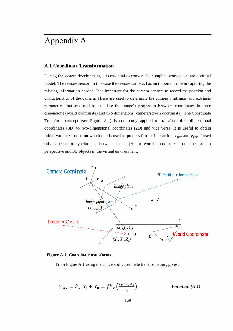
169
Appendix A
A.1 Coordinate Transformation
During the system development, it is essential to convert the complete workspace into a virtual
model. The remote sensor, in this case the remote camera, has an important role in capturing the
missing information needed. It is important for the camera sensors to record the position and
characteristics of the camera. These are used to determine the camera‘s intrinsic and extrinsic
parameters that are used to calculate the image‘s projection between coordinates in three
dimensions (world coordinate) and two dimensions (camera/screen coordinate). The Coordinate
Transform concept (see Figure A.1) is commonly applied to transform three-dimensional
coordinates (3D) to two-dimensional coordinates (2D) and vice versa. It is useful to obtain
initial variables based on which one is used to process further interaction, and . I used
this concept to synchronise between the object in world coordinates from the camera
perspective and 3D objects in the virtual environment.
Figure A.1: Coordinate transforms
From Figure A.1 using the concept of coordinate transformation, gives:
(
) Equation (A.1)
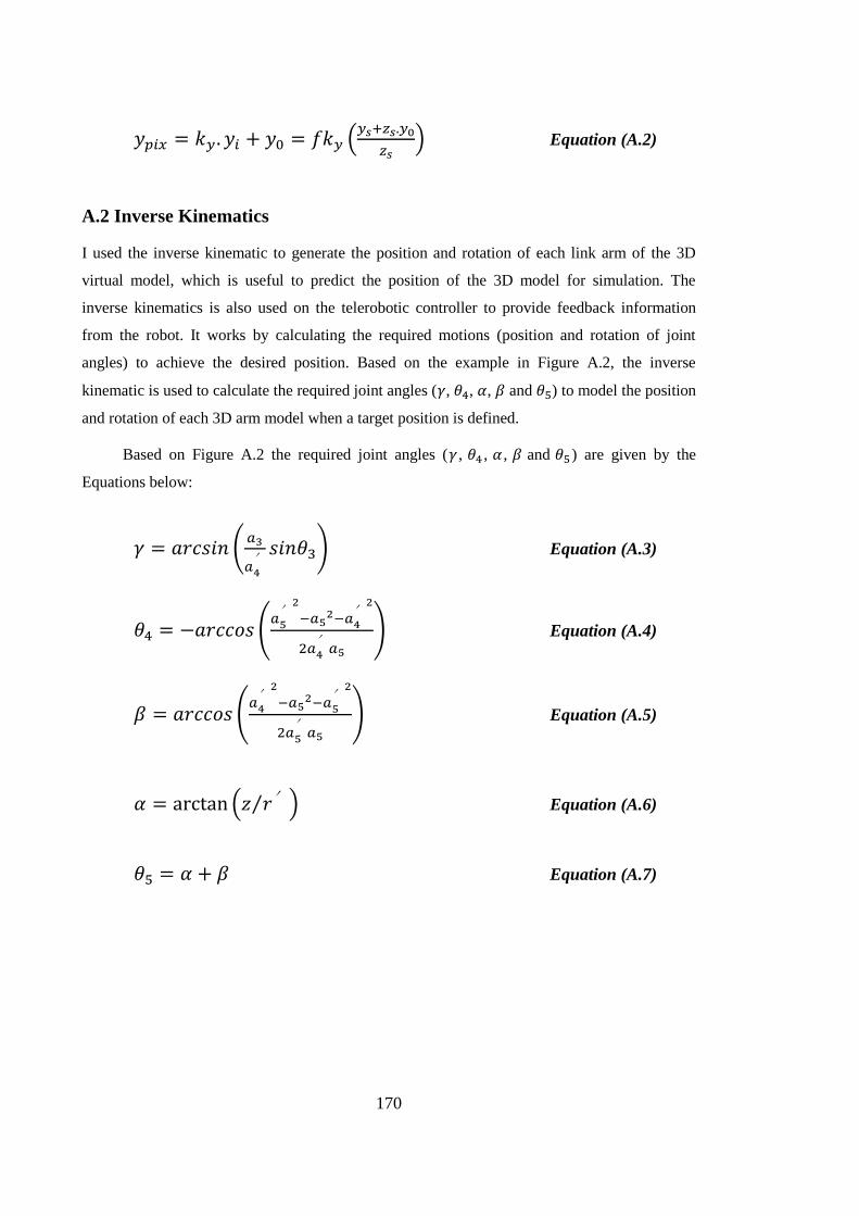
170
(
) Equation (A.2)
A.2 Inverse Kinematics
I used the inverse kinematic to generate the position and rotation of each link arm of the 3D
virtual model, which is useful to predict the position of the 3D model for simulation. The
inverse kinematics is also used on the telerobotic controller to provide feedback information
from the robot. It works by calculating the required motions (position and rotation of joint
angles) to achieve the desired position. Based on the example in Figure A.2, the inverse
kinematic is used to calculate the required joint angles ( , , , and ) to model the position
and rotation of each 3D arm model when a target position is defined.
Based on Figure A.2 the required joint angles ( , , , and ) are given by the
Equations below:
(
′ ) Equation (A.3)
( ′
′
′
) Equation (A.4)
( ′
′
′
) Equation (A.5)
( ′⁄ ) Equation (A.6)
Equation (A.7)
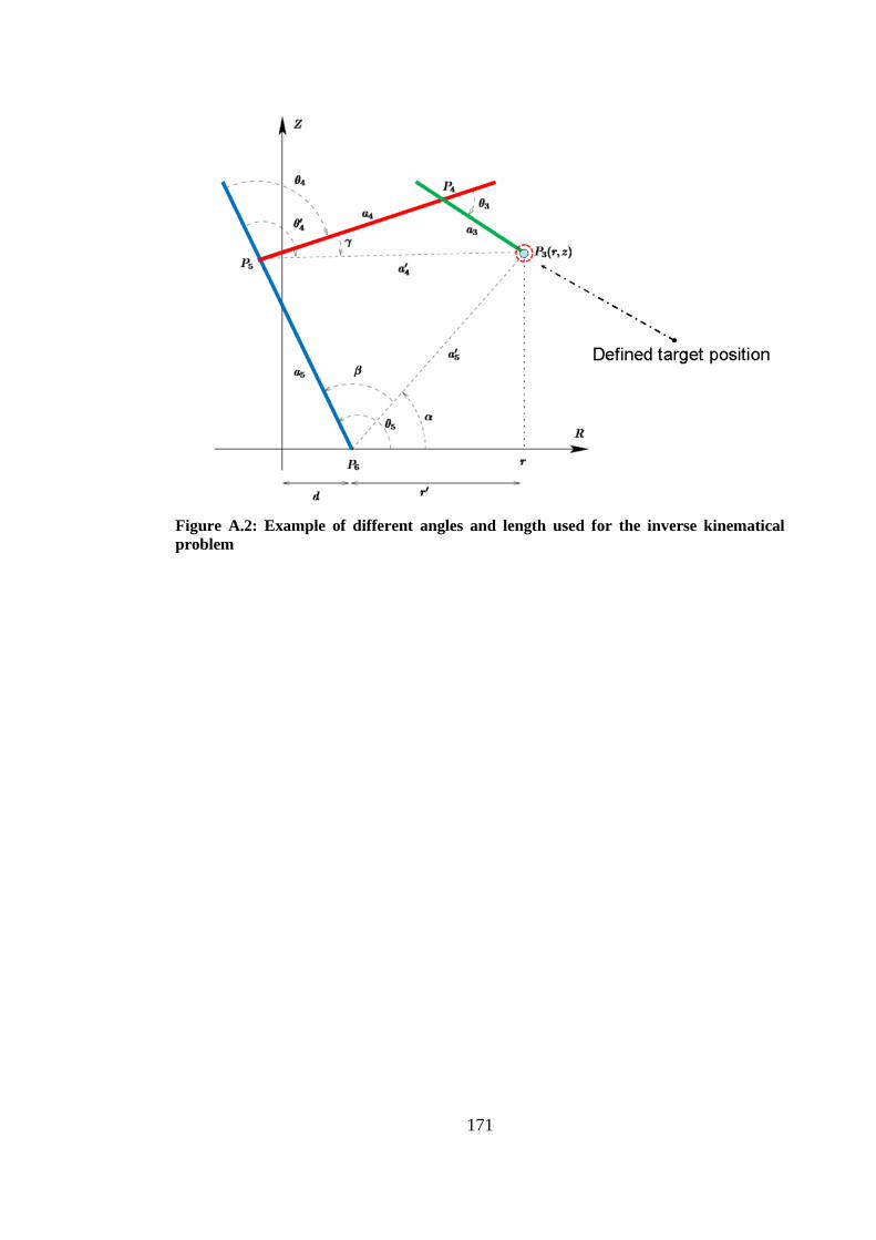
171
Figure A.2: Example of different angles and length used for the inverse kinematical
problem

172

173
Appendix B
B.1 User Study Questionnaire for Experiment 1
User Study Questionnaire Thank you for taking the time to fill in this questionnaire. Please respond as truthfully
as possible, as criticism is appreciated as much as positive feedback.
Personal Details 1. Name:____________________________________
2. Age: ________________
3. Sex: male female
4. Occupation (if you are a student, please specify your major):
5. How often do you use a computer?
Never Occasionally Often (at least one hour a
day)
6. How often do you play virtual world video games?
Never Occasionally Often (at least one hour a
day)
7. Do you know or ever heard about Games Second Life?
Yes No
8. Do you know or ever heard about Sims Urban application?
Yes No
9. Do you any have problems with colorblindness?
Yes No
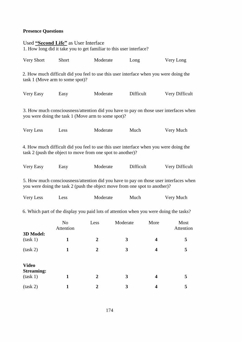
174
Presence Questions
Used “Second Life” as User Interface 1. How long did it take you to get familiar to this user interface?
Very Short Short Moderate Long Very Long
2. How much difficult did you feel to use this user interface when you were doing the
task 1 (Move arm to some spot)?
Very Easy Easy Moderate Difficult Very Difficult
3. How much consciousness/attention did you have to pay on those user interfaces when
you were doing the task 1 (Move arm to some spot)?
Very Less Less Moderate Much Very Much
4. How much difficult did you feel to use this user interface when you were doing the
task 2 (push the object to move from one spot to another)?
Very Easy Easy Moderate Difficult Very Difficult
5. How much consciousness/attention did you have to pay on those user interfaces when
you were doing the task 2 (push the object move from one spot to another)?
Very Less Less Moderate Much Very Much
6. Which part of the display you paid lots of attention when you were doing the tasks?
No
Attention
Less Moderate More Most
Attention
3D Model:
(task 1) 1 2 3 4 5
(task 2) 1 2 3 4 5
Video
Streaming:
(task 1) 1 2 3 4 5
(task 2) 1 2 3 4 5
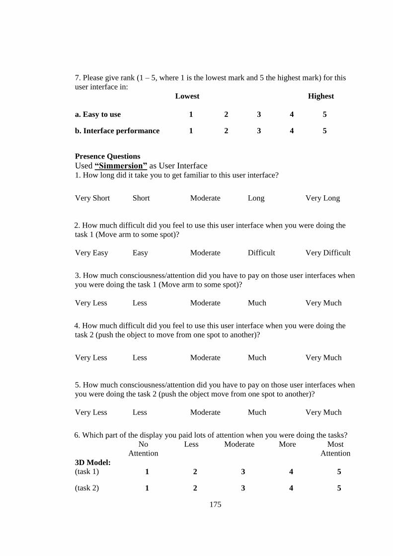
175
7. Please give rank (1 – 5, where 1 is the lowest mark and 5 the highest mark) for this
user interface in:
Lowest Highest
a. Easy to use 1 2 3 4 5
b. Interface performance 1 2 3 4 5
Presence Questions
Used “Simmersion” as User Interface 1. How long did it take you to get familiar to this user interface?
Very Short Short Moderate Long Very Long
2. How much difficult did you feel to use this user interface when you were doing the
task 1 (Move arm to some spot)?
Very Easy Easy Moderate Difficult Very Difficult
3. How much consciousness/attention did you have to pay on those user interfaces when
you were doing the task 1 (Move arm to some spot)?
Very Less Less Moderate Much Very Much
4. How much difficult did you feel to use this user interface when you were doing the
task 2 (push the object to move from one spot to another)?
Very Less Less Moderate Much Very Much
5. How much consciousness/attention did you have to pay on those user interfaces when
you were doing the task 2 (push the object move from one spot to another)?
Very Less Less Moderate Much Very Much
6. Which part of the display you paid lots of attention when you were doing the tasks?
No
Attention
Less Moderate More Most
Attention
3D Model:
(task 1) 1 2 3 4 5
(task 2) 1 2 3 4 5
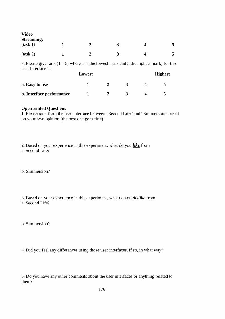
176
Video
Streaming:
(task 1) 1 2 3 4 5
(task 2) 1 2 3 4 5
7. Please give rank (1 – 5, where 1 is the lowest mark and 5 the highest mark) for this
user interface in:
Lowest Highest
a. Easy to use 1 2 3 4 5
b. Interface performance 1 2 3 4 5
Open Ended Questions 1. Please rank from the user interface between ―Second Life‖ and ―Simmersion‖ based
on your own opinion (the best one goes first).
2. Based on your experience in this experiment, what do you like from
a. Second Life?
b. Simmersion?
3. Based on your experience in this experiment, what do you dislike from
a. Second Life?
b. Simmersion?
4. Did you feel any differences using those user interfaces, if so, in what way?
5. Do you have any other comments about the user interfaces or anything related to
them?
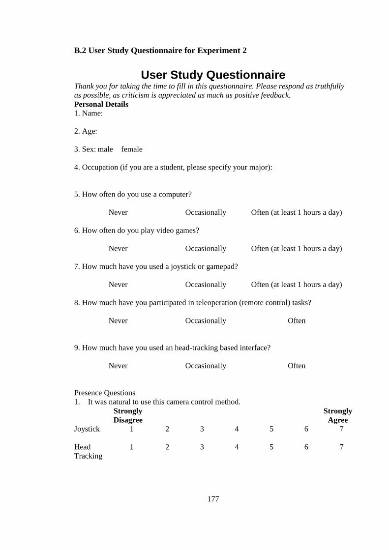
177
B.2 User Study Questionnaire for Experiment 2
User Study Questionnaire Thank you for taking the time to fill in this questionnaire. Please respond as truthfully
as possible, as criticism is appreciated as much as positive feedback.
Personal Details 1. Name:
2. Age:
3. Sex: male female
4. Occupation (if you are a student, please specify your major):
5. How often do you use a computer?
Never Occasionally Often (at least 1 hours a day)
6. How often do you play video games?
Never Occasionally Often (at least 1 hours a day)
7. How much have you used a joystick or gamepad?
Never Occasionally Often (at least 1 hours a day)
8. How much have you participated in teleoperation (remote control) tasks?
Never Occasionally Often
9. How much have you used an head-tracking based interface?
Never Occasionally Often
Presence Questions
1. It was natural to use this camera control method.
Strongly
Disagree
Strongly
Agree Joystick
1 2 3 4 5 6 7
Head
Tracking
1 2 3 4 5 6 7
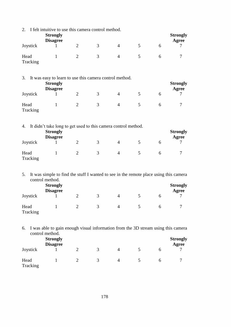
178
2. I felt intuitive to use this camera control method.
Strongly
Disagree
Strongly
Agree Joystick
1 2 3 4 5 6 7
Head
Tracking
1 2 3 4 5 6 7
3. It was easy to learn to use this camera control method.
Strongly
Disagree
Strongly
Agree Joystick
1 2 3 4 5 6 7
Head
Tracking
1 2 3 4 5 6 7
4. It didn‘t take long to get used to this camera control method.
Strongly
Disagree
Strongly
Agree Joystick
1 2 3 4 5 6 7
Head
Tracking
1 2 3 4 5 6 7
5. It was simple to find the stuff I wanted to see in the remote place using this camera
control method.
Strongly
Disagree
Strongly
Agree Joystick
1 2 3 4 5 6 7
Head
Tracking
1 2 3 4 5 6 7
6. I was able to gain enough visual information from the 3D stream using this camera
control method.
Strongly
Disagree
Strongly
Agree Joystick
1 2 3 4 5 6 7
Head
Tracking
1 2 3 4 5 6 7
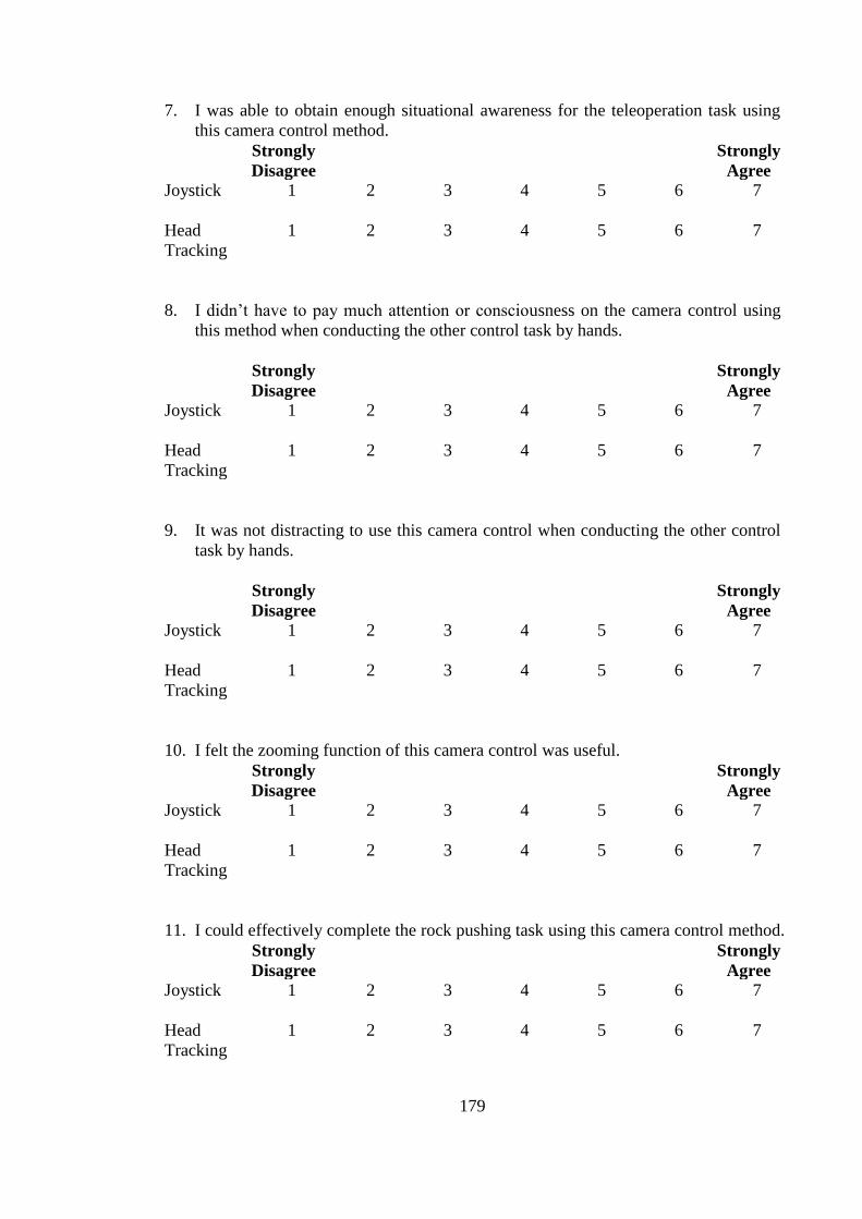
179
7. I was able to obtain enough situational awareness for the teleoperation task using
this camera control method.
Strongly
Disagree
Strongly
Agree Joystick
1 2 3 4 5 6 7
Head
Tracking
1 2 3 4 5 6 7
8. I didn‘t have to pay much attention or consciousness on the camera control using
this method when conducting the other control task by hands.
Strongly
Disagree
Strongly
Agree Joystick
1 2 3 4 5 6 7
Head
Tracking
1 2 3 4 5 6 7
9. It was not distracting to use this camera control when conducting the other control
task by hands.
Strongly
Disagree
Strongly
Agree Joystick
1 2 3 4 5 6 7
Head
Tracking
1 2 3 4 5 6 7
10. I felt the zooming function of this camera control was useful.
Strongly
Disagree
Strongly
Agree Joystick
1 2 3 4 5 6 7
Head
Tracking
1 2 3 4 5 6 7
11. I could effectively complete the rock pushing task using this camera control method.
Strongly
Disagree
Strongly
Agree Joystick
1 2 3 4 5 6 7
Head
Tracking
1 2 3 4 5 6 7
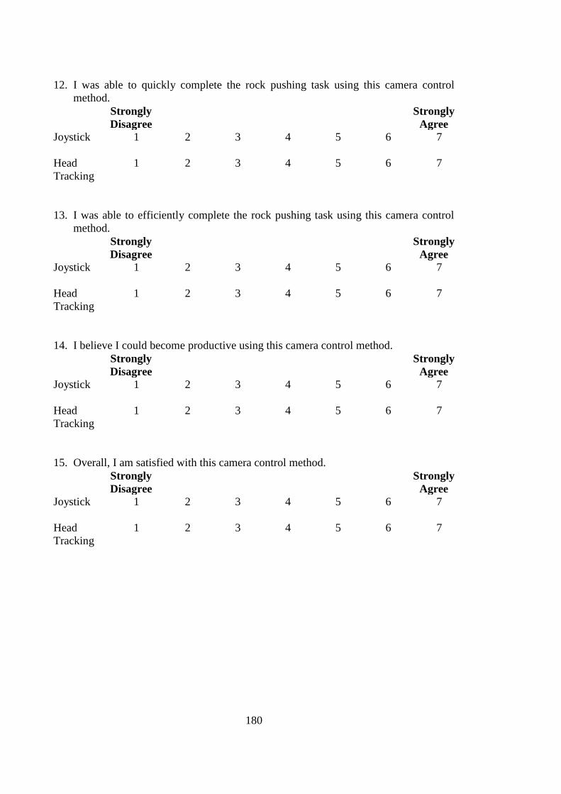
180
12. I was able to quickly complete the rock pushing task using this camera control
method.
Strongly
Disagree
Strongly
Agree Joystick
1 2 3 4 5 6 7
Head
Tracking
1 2 3 4 5 6 7
13. I was able to efficiently complete the rock pushing task using this camera control
method.
Strongly
Disagree
Strongly
Agree Joystick
1 2 3 4 5 6 7
Head
Tracking
1 2 3 4 5 6 7
14. I believe I could become productive using this camera control method.
Strongly
Disagree
Strongly
Agree Joystick
1 2 3 4 5 6 7
Head
Tracking
1 2 3 4 5 6 7
15. Overall, I am satisfied with this camera control method.
Strongly
Disagree
Strongly
Agree Joystick
1 2 3 4 5 6 7
Head
Tracking
1 2 3 4 5 6 7
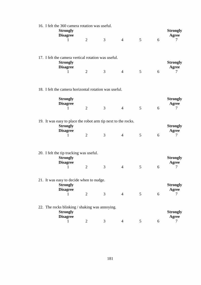
181
16. I felt the 360 camera rotation was useful.
Strongly
Disagree
Strongly
Agree 1 2 3 4 5 6 7
17. I felt the camera vertical rotation was useful.
Strongly
Disagree
Strongly
Agree 1 2 3 4 5 6 7
18. I felt the camera horizontal rotation was useful.
Strongly
Disagree
Strongly
Agree 1 2 3 4 5 6 7
19. It was easy to place the robot arm tip next to the rocks.
Strongly
Disagree
Strongly
Agree 1 2 3 4 5 6 7
20. I felt the tip tracking was useful.
Strongly
Disagree
Strongly
Agree 1 2 3 4 5 6 7
21. It was easy to decide when to nudge.
Strongly
Disagree
Strongly
Agree 1 2 3 4 5 6 7
22. The rocks blinking / shaking was annoying.
Strongly
Disagree
Strongly
Agree 1 2 3 4 5 6 7
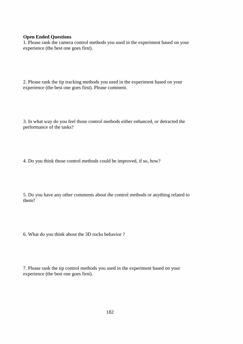
182
Open Ended Questions 1. Please rank the camera control methods you used in the experiment based on your
experience (the best one goes first).
2. Please rank the tip tracking methods you used in the experiment based on your
experience (the best one goes first). Please comment.
3. In what way do you feel those control methods either enhanced, or detracted the
performance of the tasks?
4. Do you think those control methods could be improved, if so, how?
5. Do you have any other comments about the control methods or anything related to
them?
6. What do you think about the 3D rocks behavior ?
7. Please rank the tip control methods you used in the experiment based on your
experience (the best one goes first).
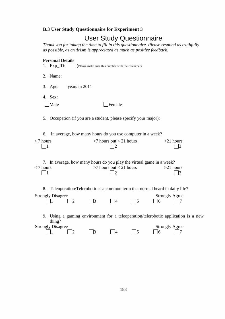
183
B.3 User Study Questionnaire for Experiment 3
User Study Questionnaire Thank you for taking the time to fill in this questionnaire. Please respond as truthfully
as possible, as criticism is appreciated as much as positive feedback.
Personal Details 1. Exp_ID: (Please make sure this number with the reseacher)
2. Name:
3. Age: years in 2011
4. Sex:
5. Occupation (if you are a student, please specify your major):
6. In average, how many hours do you use computer in a week?
7. In average, how many hours do you play the virtual game in a week?
8. Teleoperation/Telerobotic is a common term that normal heard in daily life?
9. Using a gaming environment for a teleoperation/telerobotic application is a new
thing?
Male Female
< 7 hours >7 hours but < 21 hours >21 hours
1 2 3
< 7 hours >7 hours but < 21 hours >21 hours
1 2 3
Strongly Disagree Strongly Agree
1 2 3 4 5 6 7
Strongly Disagree Strongly Agree
1 2 3 4 5 6 7
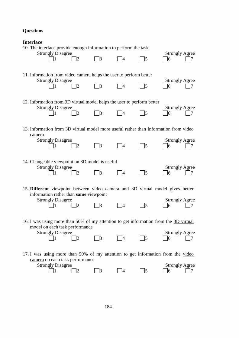
184
Questions
Interface 10. The interface provide enough information to perform the task
11. Information from video camera helps the user to perform better
12. Information from 3D virtual model helps the user to perform better
13. Information from 3D virtual model more useful rather than Information from video
camera
14. Changeable viewpoint on 3D model is useful
15. Different viewpoint between video camera and 3D virtual model gives better
information rather than same viewpoint
16. I was using more than 50% of my attention to get information from the 3D virtual
model on each task performance
17. I was using more than 50% of my attention to get information from the video
camera on each task performance
Strongly Disagree Strongly Agree
1 2 3 4 5 6 7
Strongly Disagree Strongly Agree
1 2 3 4 5 6 7
Strongly Disagree Strongly Agree
1 2 3 4 5 6 7
Strongly Disagree Strongly Agree
1 2 3 4 5 6 7
Strongly Disagree Strongly Agree
1 2 3 4 5 6 7
Strongly Disagree Strongly Agree
1 2 3 4 5 6 7
Strongly Disagree Strongly Agree
1 2 3 4 5 6 7
Strongly Disagree Strongly Agree
1 2 3 4 5 6 7
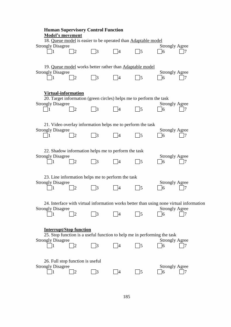
185
Human Supervisory Control Function
Model‟s movement 18. Queue model is easier to be operated than Adaptable model
19. Queue model works better rather than Adaptable model
Virtual-information
20. Target information (green circles) helps me to perform the task
21. Video overlay information helps me to perform the task
22. Shadow information helps me to perform the task
23. Line information helps me to perform the task
24. Interface with virtual information works better than using none virtual information
Interrupt/Stop function
25. Stop function is a useful function to help me in performing the task
26. Full stop function is useful
Strongly Disagree Strongly Agree
1 2 3 4 5 6 7
Strongly Disagree Strongly Agree
1 2 3 4 5 6 7
Strongly Disagree Strongly Agree
1 2 3 4 5 6 7
Strongly Disagree Strongly Agree
1 2 3 4 5 6 7
Strongly Disagree Strongly Agree
1 2 3 4 5 6 7
Strongly Disagree Strongly Agree
1 2 3 4 5 6 7
Strongly Disagree Strongly Agree
1 2 3 4 5 6 7
Strongly Disagree Strongly Agree
1 2 3 4 5 6 7
Strongly Disagree Strongly Agree
1 2 3 4 5 6 7
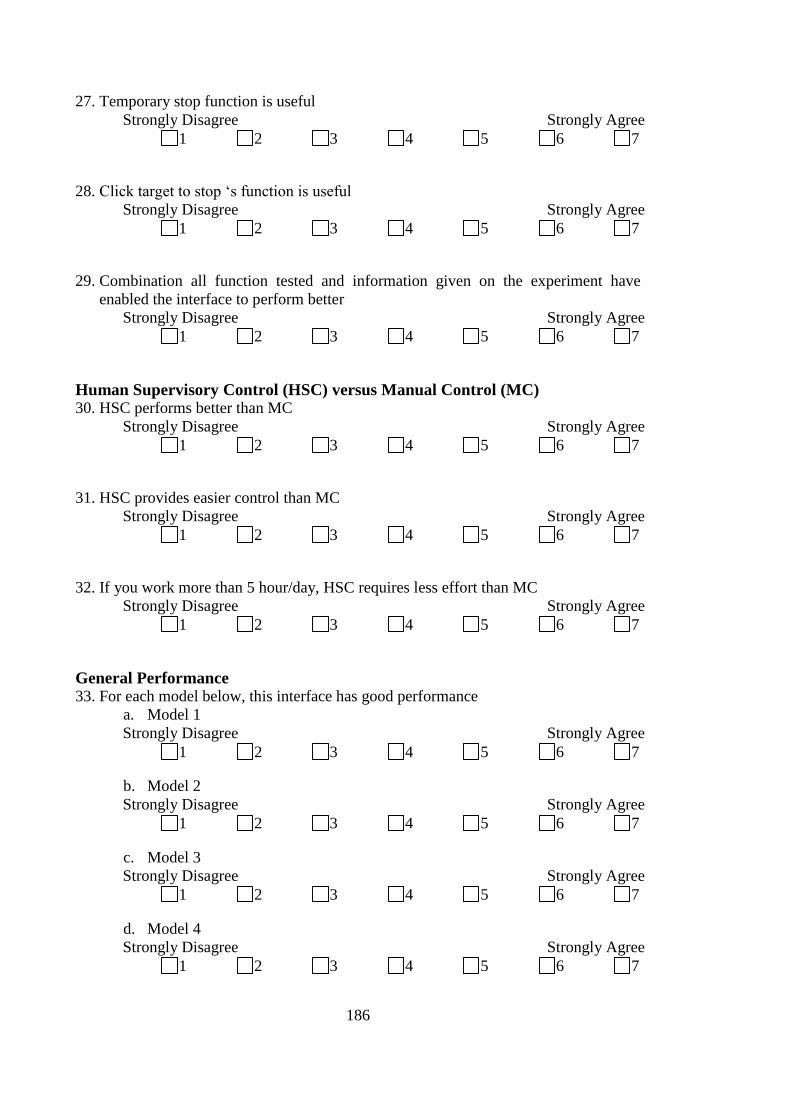
186
27. Temporary stop function is useful
28. Click target to stop ‗s function is useful
29. Combination all function tested and information given on the experiment have
enabled the interface to perform better
Human Supervisory Control (HSC) versus Manual Control (MC) 30. HSC performs better than MC
31. HSC provides easier control than MC
32. If you work more than 5 hour/day, HSC requires less effort than MC
General Performance 33. For each model below, this interface has good performance
a. Model 1
b. Model 2
c. Model 3
d. Model 4
Strongly Disagree Strongly Agree
1 2 3 4 5 6 7
Strongly Disagree Strongly Agree
1 2 3 4 5 6 7
Strongly Disagree Strongly Agree
1 2 3 4 5 6 7
Strongly Disagree Strongly Agree
1 2 3 4 5 6 7
Strongly Disagree Strongly Agree
1 2 3 4 5 6 7
Strongly Disagree Strongly Agree
1 2 3 4 5 6 7
Strongly Disagree Strongly Agree
1 2 3 4 5 6 7
Strongly Disagree Strongly Agree
1 2 3 4 5 6 7
Strongly Disagree Strongly Agree
1 2 3 4 5 6 7
Strongly Disagree Strongly Agree
1 2 3 4 5 6 7
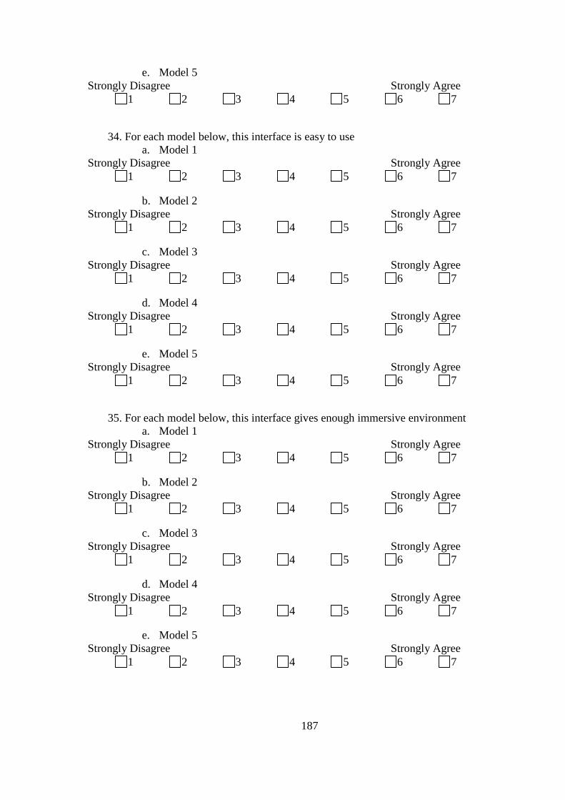
187
e. Model 5
34. For each model below, this interface is easy to use
a. Model 1
b. Model 2
c. Model 3
d. Model 4
e. Model 5
35. For each model below, this interface gives enough immersive environment
a. Model 1
b. Model 2
c. Model 3
d. Model 4
e. Model 5
Strongly Disagree Strongly Agree
1 2 3 4 5 6 7
Strongly Disagree Strongly Agree
1 2 3 4 5 6 7
Strongly Disagree Strongly Agree
1 2 3 4 5 6 7
Strongly Disagree Strongly Agree
1 2 3 4 5 6 7
Strongly Disagree Strongly Agree
1 2 3 4 5 6 7
Strongly Disagree Strongly Agree
1 2 3 4 5 6 7
Strongly Disagree Strongly Agree
1 2 3 4 5 6 7
Strongly Disagree Strongly Agree
1 2 3 4 5 6 7
Strongly Disagree Strongly Agree
1 2 3 4 5 6 7
Strongly Disagree Strongly Agree
1 2 3 4 5 6 7
Strongly Disagree Strongly Agree
1 2 3 4 5 6 7
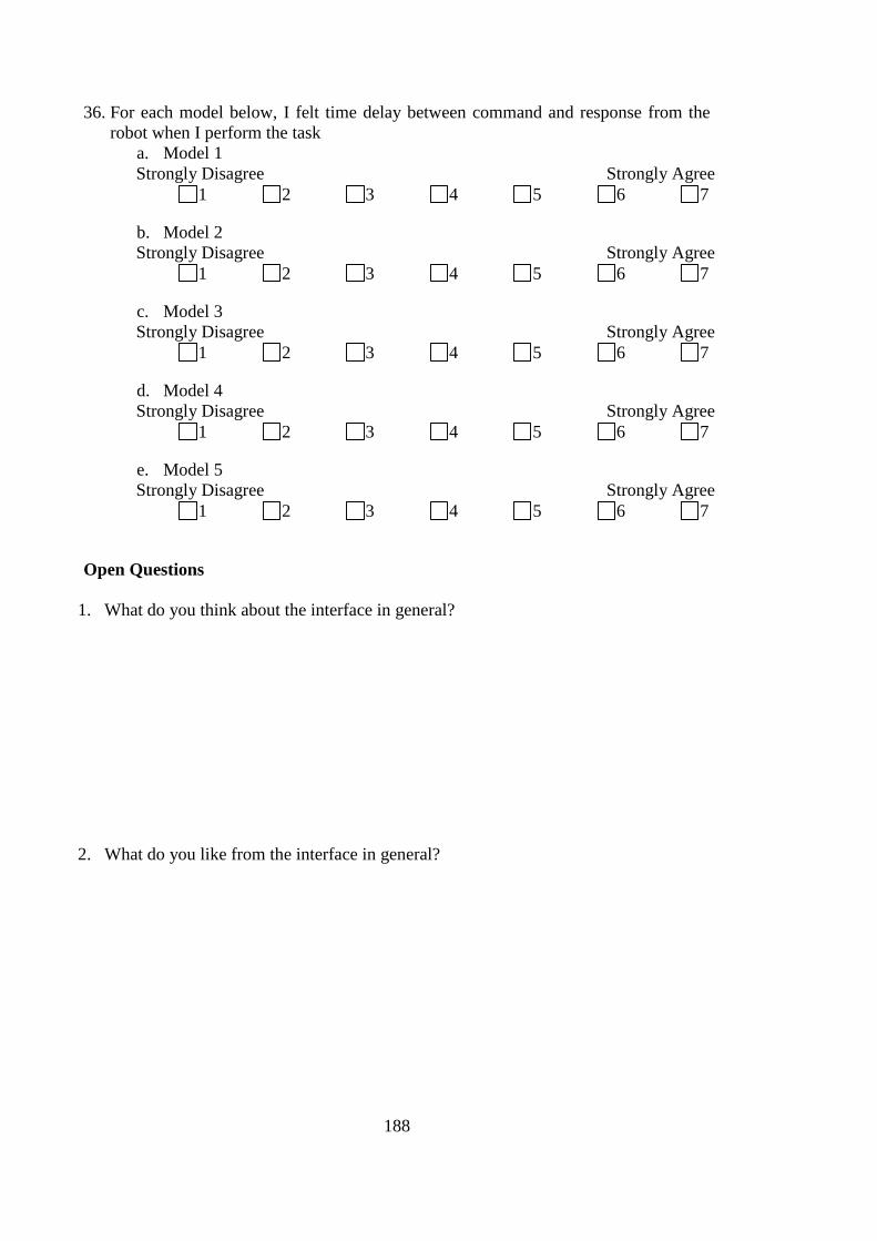
188
36. For each model below, I felt time delay between command and response from the
robot when I perform the task
a. Model 1
b. Model 2
c. Model 3
d. Model 4
e. Model 5
Open Questions
1. What do you think about the interface in general?
2. What do you like from the interface in general?
Strongly Disagree Strongly Agree
1 2 3 4 5 6 7
Strongly Disagree Strongly Agree
1 2 3 4 5 6 7
Strongly Disagree Strongly Agree
1 2 3 4 5 6 7
Strongly Disagree Strongly Agree
1 2 3 4 5 6 7
Strongly Disagree Strongly Agree
1 2 3 4 5 6 7
189
3. In general which part in the interface need to be improved?
4. Do you have any additional comment regarding to the experiment?
Thank you for your participation in this Experiment
Please do ―Save As‖ and name this document with your Exp_ID

190
191
References
[1] T. Fong and C. Thorpe, "Vehicle Teleoperation Interfaces," presented at the
Autonomous Robots, Netherlands, 2001.
[2] T. B. Sheridan, Telerobotics, Automation, and Human Supervisory Control. London,
England: The MIT Press Cambridge, Massachusetts, 1992.
[3] X. Yang and Q. Chen, "Virtual Reality Tools for Internet-Based Robotic
Teleoperation," presented at the Eight IEEE International Symposium on Distributed
Simulation and Real-Time Applications (DS-RT'04), 2004.
[4] M. Bajura, et al., "Merging Virtual Objects with the Real World: Seeing Ultrasound
Imagery within the Patient," in SIGGRAPH ’92 Chicago, 1992, pp. 203-210.
[5] E. Duff, et al., "The development of a Telerobotic Rock Breaker," in 7th International
Conference on Field and Service Robots (FSR 2009), Cambridge, Massachusetts, USA,
2009, pp. 1-10.
[6] D. Hainsworth, "Teleoperation User Interfaces for Mining Robotics," Autonomous
Robots, vol. 11, pp. 19-28, 2001.
[7] T. Fong, et al., "PdaDriver: A Handheld System for Remote Driving," presented at the
IEEE International Conference on Advanced Robotics, Coimbra, Portugal, 2003.
[8] S. Grange, et al., "Effective Vehicle Teleoperation on the World Wide Web," presented
at the IEEE International Conference on Robotics and Automation, San Francisco, CA,
2000.
[9] R. Meire, et al., "A Sensor Fusion Based User Interface for Vehicle Teleoperation,"
presented at the In International Conference on Field and Service Robotics, 1999.
[10] Q. Lin and C. Kuo, "On Applying Virtual Reality To Underwater Robot Tele-operation
and Pilot Training," The International Journal Of Virtual Reality, vol. 5, pp. 1-19, 2001.
[11] A. Monferrer and D. Bonyuet, "Cooperative Robot Teleoperation through Virtual
Reality Interface," presented at the The Sixth International Conference on Information
Visualisation (IV'02), 2002.
192
[12] P. Paul, et al., "Augmented Virtuality Based on Stereoscopic Reconstruction in
Multimodal Image-Guided Neurosurgery: Methods and Performance Evaluation," 2005,
pp. 1500-1511.
[13] J. C. Lane, et al., "Advanced Operator Interface Design for Complex Space Telerobots,"
Autonomous Robots, vol. 11, pp. 49-58, 2001.
[14] R. R. Murphy, Introduction to AI Robotics: The MIT Press, 2000.
[15] K. G. Shin and X. Cui, "Computing time-delay and its effects on real-time control
systems," IEEE Transactions Control Systems Technology, vol. 3, pp. 218–224, 1995.
[16] J. C. Lane, et al., "Effects of time-delay on telerobotic control of neutral buoyancy
vehicles," IEEE International Conference on Robotics and Automation, vol. 3, pp.
2874–2879, 2002.
[17] T. Fong, et al., "Collaborative Control: A robot-Centric Model for Vehicle
Teleoperation," AAAI Technical Report SS-99-06, pp. 33-40, 1998.
[18] L. A. Nguyen, et al., "Virtual Reality Interfaces for Visualization and Control of
Remote Vehicles," Autonomous Robots, vol. 11, pp. 59-68, 2001.
[19] R. Aracil, et al., "The Human Role in Telerobotics," in Advances in Telerobotics, M.
Ferre, et al., Eds., ed: Springer, 2007, pp. 11-24.
[20] V. Harutyunyan, et al., "Cognitive Telepresence in Human-Robot Interactions," Journal
of Human-Robot Interaction, vol. 1, pp. 158-182, 2012.
[21] N.-J. P. Laboratory, in
http://www.robotics.jpl.nasa.gov/applications/applicationArea-.cfm?App=11 vol.
71.3KB, nasa_RSVP_interface.jpg, Ed., ed.
[22] S. Westerberg and A. Shiriaev, "Virtual Environment-Based Teleoperation of Forestry
Machines: Designing Future Interaction Methods," Journal of Human-Robot Interaction,
vol. 2, pp. 84-110, 2013.
[23] D. Verna. (1999). Virtual Reality and Tele-operation: a Common Framework.
Available: http://www.lrde.epita.fr/~didier/research/verna.01.sci.pdf
193
[24] A. Steinfeld, et al., "Common metrics for human-robot interaction," presented at the
Proceedings of the 1st ACM SIGCHI/SIGART conference on Human-robot interaction,
Salt Lake City, Utah, USA, 2006.
[25] S. Grange, et al., "Overview of the Delta Haptic Device," presented at the
Eurohaptics‘01, 2001.
[26] C. Gunn, et al., "Trans-world Haptic Collaboration," presented at the SIGGRAPH, San
Diego,USA, 2003.
[27] W. Amai, et al., "Hands-free operation of a small mobile robot," Autonomous Robots,
vol. 11(1), pp. 67–73, 2001.
[28] J. Wang, et al., "USAR: A Game Based Simuation for Teleoperation," in the 47th
Annual Meeting of the Human Factors and Ergonomics Society, Denver, CO, 2003, pp.
13-17.
[29] K. Ponto, et al., "Virtual Bounds: A Teleoperated Mixed Reality," Virtual Reality, vol.
10, pp. 41-47, 2006.
[30] M. Sugimoto, et al., "Augmented Coliseum: Display-Based Computing for Augmented
Reality Inspiration Computing Robot," in Proceedings of Horizontal Interactive
Human-Computer Systems, 2005, pp. 3-8.
[31] G. Metaxas, et al., "SCORPIODROME: An Exploration in Mixed Reality Social
Gaming for Children. In Proceedings of ACM conference on Advances in Computer
Entertainment," presented at the Proceedings of ACM conference on Advances in
Computer Entertainment, 2005.
[32] H. Tamura, et al., "Mixed Reality: Future Dreams Seen at the Border between Real and
Virtual Worlds," in IEEE Computer Graphics and Applications, 2001, pp. 64 - 70.
[33] J. Richer and J. L. Drury, "A video game-based framework for analyzing human-robot
interaction: characterizing interface design in real-time interactive multimedia
applications," in HRI '06 Proceedings of the 1st ACM SIGCHI/SIGART conference on
Human-robot interaction, 2006, pp. 266 - 273
[34] P. Bourke, "Evaluating Second Life as a tool for collaborative scientific visualisation,"
presented at the Computer Games and Allied Technology Conference, Singapore, 2008.
194
[35] J. Chung and H. J. Gardner, "Measuring Temporal Variation in Presence During Game
Playing," in 8th International Conference on Virtual Reality Continuum and its
Applications in Industry, New York, NY, USA, 2009, pp. 163-168.
[36] T. H. Schou, "Constructing an Immersive Virtual Reality Environment using Modern
Gaming Technologies," Bachelor of Software Engineering Department of Computer
Science, The Australian National University, Canberra, 2008.
[37] T. Fong, et al., "A Personal User Interface for Collaborative Human-Robot
Exploration," presented at the International Symposioum on Artificial Intelegence,
Robotics, and Automtion in Space, Montreal, Canada, 2001.
[38] T. Fong, et al., "Multi-Robot Remote Driving With Collaborative Control," in IEEE
Transactions on Industrial Electronics, 2003 pp. 699-704.
[39] D. Zhu, et al., "Exploring Camera Viewpoint Control Models for a Multi-Tasking
Setting in Teleoperation," in Computer Human Interaction 2011, Vancouver, BC,
Canada, 2011, pp. 53-62.
[40] A. Gazzard, "Playing in a virtual World: Exploration and Aspect of Play," in 17th
International Conference on Artificial Reality and Telexistence, 2007, pp. 288-289.
[41] W. J. Au, The making of Second Life : notes from the new world, 1st ed ed. New York:
Collins, 2008.
[42] A. Weber, et al., Creating Your World: The Official Guide to Advanced Content
Creation for Second Life. Canada: Wiley Publishing, Inc., Indianapollis, Indiana, 2008.
[43] B. A. White, Second Life: A Guide to Your Virtual World. United State of America:
Quo Publishing, 2008.
[44] S. Robbins and M. Bell, Second Life for Dummies. Canada: John Willey & Sons
Publishing, Inc., Indianapolis, Indiana., 2011.
[45] v3image, A Beginner's Guide to Second Life version 1.1: Archebooks Publishing
Incorporated, 2007.
[46] (17/12/2009). What is Second Life? Available: http://secondlife.com/whatis/?lang=en-
US
195
[47] (9/3/2010). What is Mycosm? Available: http://www.mycosm.com/faq.php
[48] (16/12/2010). Create Games with Unity. Available: http://unity3d.com/create-games/
[49] (2/8/2010). Unity3D. Available: http://unity3d.com/unity/
[50] (2/8/2010). Unity3D Documentation. Available: http://unity3d.com/support/docum-
entation/
[51] E. Caoili. (2008, 9/3/2011). Unity to Support Wii Console as Authorized Middleware
Provider. Available: http://www.gamasutra.com/php-bin/news_index.php?story=18840
[52] J. Heaton, Introduction to Linden Scripting Language for Second Life: Heaton Research,
2007.
[53] A. S. Lang and J.-C. Bradley, "Chemistry in Second Life," Chemistry Central Journal,
vol. 3, 2009, doi:10.1186/1752-153X-3-14.
[54] P. Cohen. (2008, 8/12/12). Unity Game Engine Coming to iPhone. Available:
http://www.macworld.com/article/132771/2008/04/unity.html
[55] T. W. Fong, et al., "Active Interfaces for Vehicle Teleoperation," in SPIE Robotics and
Machines Perception Working Group vol. 10 (1), March ed, 2001.
[56] T. Fong, et al., "Advance Interface for Vehicle Teleoperation: Collaborative Control,
Sensor Fusion Displays, and Remote Driving Tools," Autononomus Robots, vol. 11, p. 8,
2001.
[57] T. Fong, et al., "Multi-robot remote driving with collaborative control," presented at the
IEEE International Workshop on Robot-Human Interactive Communication, Bordeaux
and Paris, France, 2001.
[58] T. Fong, et al., "Robot As Partner: Vehicle Teleoperation with Collaborative Control,"
in In Multi-Robot Systems: From Swarms to Intelligent Automata, Proceedings from
the 2002 NRL Workshop on Multi-Robot Systems 2002, pp. 195-102.
[59] T. Fong, et al., "Collaboration, Dialoge, and Human-Robot Interaction," presented at the
10th International Symposium of Robotics Research, Lorne, Victoria, Australia and
London, Springer-Verlag 2002.
196
[60] T. B. Sheridan, Human and Automation: System Design and Research Issue vol. 3.
Santa Monica: A John Willey & Sons, Inc., 2002.
[61] P. k. Verma, Performance Estimation of Computer Communication Networks: A
Structure Approach. United States of America: Computer Science Press, 1989.
[62] W.-K. Yoon, et al. (2009, 25/4/2010). Dual-Arm Space Robot Teleoperation. Available:
http://www.space.mech.tohoku.ac.jp/research/parm/parm-e.html
[63] M. R. Endsley, "Situation Awareness Global Assessment Technique (SAGAT),"
presented at the Proceedings of the National Aerospace and Electronics Conference
(NAECON), New York, 1988.
[64] P. Milgram, et al., "Augmented Reality: A Class of Display on The Reality-Virtuality
Continuum " Telemanipulator and Telepresence Technologies, vol. SPIE Vol. 2351, pp.
282 - 292, 1994.
[65] F. Nebout, et al., "Gesture Based Interface for Robot Control," in APCHI2010, Sanur,
Indonesia, 2010, pp. 680-685.
[66] D. Zhu, et al., "Natural Interaction Enhanced Remote Camera Control for
Teleoperation," in 28th ACM SIGCHI Conference Extended Abstract on Human Factors
in Computing Systems (CHI2010) Atlanta, Georgia, USA, 2010, pp. 3229-3234.
[67] K. Taylor and J. Trevelyan, "Australian's Telerobot On The Web," in 26th International
Symposium On Industrial Robots Singapore, 1995, pp. 39-44.
[68] M. Massimino and T. B. Sheridan, "Variable Force and Visual Feedback Effect om
Teleoperator Man-Machine Performance," in Proceddings of NASA Conference on
Space Telerobotics, Pasadena, CA, 1989, pp. 89-98.
[69] S. Hughes, et al., "Camera Control and Decoupled Motion for Teleoperation," in IEEE
International Conference on Systems, Man and Cybernetics, 2003, pp. 1339-1344
[70] D. Zhu, et al., "The Development of a Novel Eye Tracking Based Remote Camera
Control for Mining Teleoperation," in 7th Large Open Pit Mining Conference
(LOP2010), Perth, Western Australia, 2010, pp. 31-38.
[71] J. Child. (2011, 13/12/2012). COM Express Brings Its Multimedia Muscle to Defense.
Available: http://www.cotsjournalonline.com/articles/view/101716
197
[72] T. Reichenbach, et al., "Supervisory Control by Using Active 3D Models in-the-loop,"
in IEEE International Conference on Control Applications, 2006, pp. 1409-1413.
[73] R. A. Bartle, Designing virtual worlds Indianapolis, Ind. : New Riders Pub., 2004.
[74] R. R. Burridge and K. A. Hambuchen, "Using prediction to enhance remote robot
supervision across time delay," in Intelligent Robots and Systems, 2009. IROS 2009.
IEEE/RSJ International Conference on, 2009, pp. 5628-5634.
[75] C. Domingues, et al., "A distributed architecture for collaborative teleoperation using
virtual reality and web platforms," in CCNC'09 Proceedings of the 6th IEEE
Conference on Consumer Communications and Networking Conference, 2009, pp. 176-
180
[76] J.-Y. Didier, et al., "The MIRELA framework: modeling and analyzing mixed reality
applications using timed automata," Journal of Virtual Reality and Broadcasting, vol. 6,
pp. 249-268, 2009.
[77] C. B. Stapleton, et al., "MIXED FANTASY: Exhibition of Entertainment Research for
Mixed Reality," presented at the Proceedings of the 2nd IEEE/ACM International
Symposium on Mixed and Augmented Reality, 2003.
[78] G. Thomas, "Mixed Reality Techniques for TV and their Application for On-Set and
Pre-Visualization in Film Production," © BBC Research White Paper WHP 145, 2007.
[79] J. Young, et al., "What Is Mixed Reality, Anyway? Considering the Boundaries of
Mixed Reality in the Context of Robots," in Mixed Reality and Human-Robot
Interaction, ISCA 47. vol. Vol 47, X. Wang, Ed., 1st Edition., 2011, X, 166 p. 70 illus.
ed: Springer, 2011, pp. 1–11.
[80] O. Rashid, et al., "PAC-LAN: Mixed-Reality Gaming with RFID-Enable Mobile
Phone.," ACM Computers in Entertainment, vol. 4, pp. 1-17, 2006.
[81] M. Billinghurst and H. Kato, "Collaborative Mixed Reality " in Mixed Reality - Merging
Real and Virtual Worlds, 1999, pp. 261-284.
[82] Y. Xiong, et al., "Predictive display and interaction of telerobots based on augmented
reality," Cambridge Robotica, vol. 24, pp. 447-453, 2006.
198
[83] B.-k. Seo, et al., "Direct-Projected AR Based Interactive User Interface for Medical
Surgery," in 17th International Conference on Artificial Reality and Telexistence 2007,
2007, pp. 105-112.
[84] sportvision, in http://www.sportvision.com/sailing/officiating vol. 56.8KB,
imagerollover_sailing_broacast_2.jpg, Ed., ed.
[85] G. Schroth. (2012, 13/12/2012). Research News: If a GPS signal can’t get through,
imaging data might be the answer. Available: http://www.tum.de/nc/en/print/about-
tum/news/press-releases/short/article/30040/
[86] H. Regenbrecht, et al., "Using Augmented Virtuality for Remote Collaboration," MIT
Press Journal, vol. 13, pp. 338 - 354, 2004.
[87] H. Regenbrecht, et al., "An Augmented Virtuality Approach to 3D Videoconferencing,"
presented at the 2nd IEEE/ACM International Symposium on Mixed and Augmented
Reality, 2003.
[88] T. Saunter. (2009, 12/13/2012). Assessing an Augmented Future: What is Augmented
Reality, What are its Potential Applications in the Entertainment Industry, and What
Will its Emergence Mean for the User in Society? Available:
http://digitalcortex.net/academic/introduction/#.UMlJpeT841Y
[89] T. Blackmon and L. Stark, "Model-based supervisory control in telerobotics," Presence,
vol. 5, pp. 205 - 223, 1996.
[90] Y. F. Ho, et al., "Distributed Control for Tele-Operations," IEEE/ASME Transactions
on Mechatronics, vol. 5, pp. 100-109, 2000.
[91] F. Tendick, et al., "A supervisory telerobotic control system using model-based vision
feedback," in International Conference on Robotics and Automation, Sacramento,
California, 1991, pp. 2280 - 2285.
[92] M. L. Cummings, et al., "Human Supervisory Control Challenges in Network-Centric
Operations," Reviews of Human Factors and Ergonomics, vol. 6, pp. 34-78, May 1
2010.
[93] P. Lester. (2005, 8/2/12). A* Pathfinding for Beginners. Available:
http://www.policyalmanac.org/games/aStarTutorial.htm
199
[94] A. Patel. (2012, 8/12/12). Introduction to A*. Available:
http://theory.stanford.edu/~amitp/GameProgramming/AStarComparison.html
[95] P. H. Hammond, Theory Of Self-Adaptive Control Systems: Plenium Press, 1965.
[96] T. Sko and H. J. Gardner, "Head Tracking in First-Person Games: Interaction Using a
Web-Camera," in Human-Computer Interaction – INTERACT 2009, Berlin / Heidelberg,
2009, pp. 342-355.
[97] M. Csikszentmihalyi, et al., "FLOW: The Psychology of Optimal Experience," 2000 ©
Global Learning Communities 2000. doi: 10.1145/1077246.1077253.
[98] E. Adams, Fundamentals of Game Design, 2nd ed. Barkely: New Rides, 2009.
[99] K. Jegers. (2007) Pervasive game flow: understanding player enjoyment in pervasive
gaming. Magazine Computers in Entertainment (CIE) - Interactive entertainment. 11.
Available: http://dl.acm.org/citation.cfm?id=1236238&bnc=1
[100] G. Bradski and A. Kehler, Learning OpenCV: Computer Vision vith the OpenCV
Library: Farnham:O'Reilly, 2008.
[101] (12/6/2010). Sensable Phantom Premium 1.5. Available:
http://www.sensable.com/phantom-premium-1-5.htm/
[102] C. J. V. Rijsbergen, Information Retrieval, 2nd ed.: Butterworth-Heinemann Newton,
MA, USA, 1979.
[103] D. N. P. Murthy, et al., Weibull Model. Hoboken, New Jesery: Wiley Interscience, 2004.
[104] B. S. Blanchard, Logistics Engineering and Management, Fourth ed. Englewood Cliffs,
New Jersey.: Prentice-Hall, Inc., 1992.
[105] N. L. Johnson, et al., Continues Univariate Distribution, second edition ed. vol. 1. New
York: Wiley, 1994.
[106] K. Taylor, "Web Telerobotics: Reducing Complexity In Robotics," Doctor of
Philosophy, Department of Mechanical and Materials Engineering, University of
Western Australia, Perth, Western Australia, 1999.
[107] K. Krishnamoorthy, Handbook of Statistical Distribution with Applications. USA:
Chapman & Hall/CRC, 2006.
200
[108] I. Engineered Software. (18/12/2012). Weibull Distribution. Available:
http://www.engineeredsoftware.com/nasa/weibull.htm
[109] R. E. Walpole and R. H. Myers, Probability and Statistics for Engineers and Scientists
(Fourth Edition). New York: Macmilan, 1989.
[110] V. Ricci, "Fitting Distributin with R," cran.r-project, Feb. 21, 2005.
[111] T. Indow, "Weibull Form in Memory, Reaction Time, and Social Behaviour:
Asymptotic Distribution of Minima from Heterogenous Population," Univ. of California,
Irvine, MBS 95-04, 1995.
[112] P. Henry, et al., "RGB-D mapping: Using Kinect-style depth cameras for dense 3D
modeling of indoor environments," The International Journal of Robotics Research, vol.
31, pp. 647-663, 2012.
[113] M. Sheehan, et al., "Self-calibration for a 3D laser," The International Journal of
Robotics Research, vol. 31, pp. 675-687, 2012.