Embed Size (px)
Citation preview
1 Colorado School of Mines 2 Hatch Mott MacDonald
Evaluation of Slurry TBM Design Support Pressures using East Side Access Queens Bored Tunnels Data
Jacob Grasmick1, Mike Mooney1, Brock Rysdahl1, Eric Prantil2, Andrew Thompson2
Abstract
In practice, there are a number of approaches that can be used to determine the required support
pressures to maintain stability while tunneling in soft ground. These approaches include both
conventional rule of thumb (e.g. lateral earth pressure assumptions) and limit-equilibrium methods (e.g.
wedge stability model and reduction in face support due to slurry infiltration). The differences in
required pressures from these various methods can often be substantial, and leads to confusion and
uncertainty in which support pressure should be used. The extensive TBM instrumentation and ground
deformation monitoring during the East Side Access Queens bored tunnels project provides the
opportunity to analyze the TBM support pressures achieved and their comparison to the various
estimates for required support as well as the observed ground deformation. The results show that when
the face pressure is equal to or greater than rule of thumb and wedge stability (safety factor = 1.5)
required minimum support pressures, near zero deformation was maintained. The minor deformation
that was observed is related to the estimated annulus shield gap pressure being less than the vertical
overburden.
INTRODUCTION In soft ground tunneling, ground deformation is controlled by support pressures at the face, radial shield
and liner annular gap. Design estimates for these support pressures can be calculated using a number of
methods including both conventional ‘rule of thumb’ and more complex limit-equilibrium models. These
methods consist of their own assumptions, limitations and safety factors which can lead to substantially
different recommended support pressures to achieve stability. This can often lead to confusion and
uncertainty in which support pressure should be used.
The East Side Access Queens bored tunnels project involved the construction of four near surface,
closely spaced metro transit tunnels beneath the rail yards and mainline railroad tracks in Sunnyside
yards in Queens, New York (see Figure 1). The tunnels were constructed by the joint venture of Granite
Construction Northeast, Inc., Traylor Bros. Inc., and Frontier-Kemper Constructors, Inc. in 2011 and
2012. The tunnels were excavated using two 6.9 m (22.5 ft) diameter Herrenknecht slurry shield TBMs
primarily through variable glacial till soils and outwash deposits. The project was considered to be very
successful in that the majority of ground deformation was below 10 mm, enabling the rail tracks to
remain in service throughout the entire duration of the project.
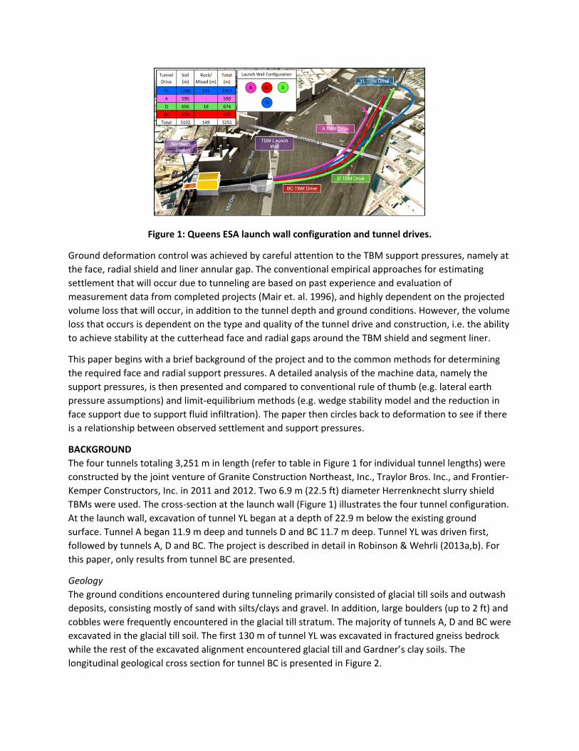
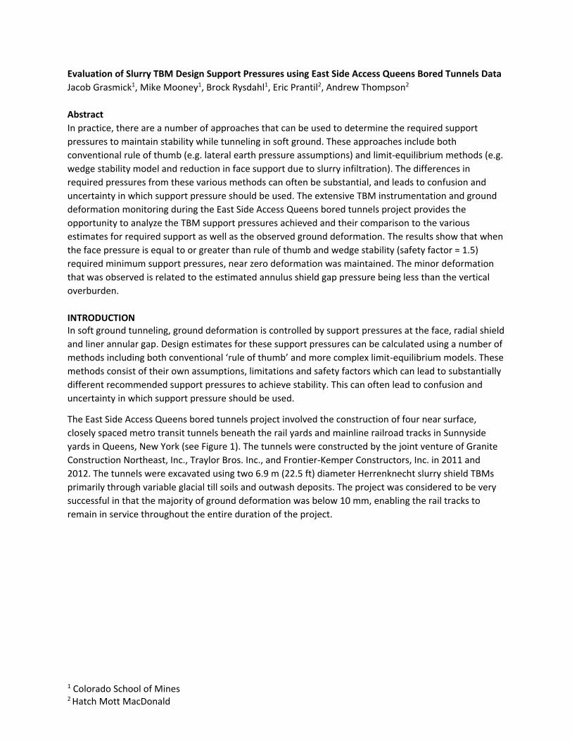
Figure 1: Queens ESA launch wall configuration and tunnel drives.
Ground deformation control was achieved by careful attention to the TBM support pressures, namely at
the face, radial shield and liner annular gap. The conventional empirical approaches for estimating
settlement that will occur due to tunneling are based on past experience and evaluation of
measurement data from completed projects (Mair et. al. 1996), and highly dependent on the projected
volume loss that will occur, in addition to the tunnel depth and ground conditions. However, the volume
loss that occurs is dependent on the type and quality of the tunnel drive and construction, i.e. the ability
to achieve stability at the cutterhead face and radial gaps around the TBM shield and segment liner.
This paper begins with a brief background of the project and to the common methods for determining
the required face and radial support pressures. A detailed analysis of the machine data, namely the
support pressures, is then presented and compared to conventional rule of thumb (e.g. lateral earth
pressure assumptions) and limit-equilibrium methods (e.g. wedge stability model and the reduction in
face support due to support fluid infiltration). The paper then circles back to deformation to see if there
is a relationship between observed settlement and support pressures.
BACKGROUND
The four tunnels totaling 3,251 m in length (refer to table in Figure 1 for individual tunnel lengths) were
constructed by the joint venture of Granite Construction Northeast, Inc., Traylor Bros. Inc., and Frontier-
Kemper Constructors, Inc. in 2011 and 2012. Two 6.9 m (22.5 ft) diameter Herrenknecht slurry shield
TBMs were used. The cross-section at the launch wall (Figure 1) illustrates the four tunnel configuration.
At the launch wall, excavation of tunnel YL began at a depth of 22.9 m below the existing ground
surface. Tunnel A began 11.9 m deep and tunnels D and BC 11.7 m deep. Tunnel YL was driven first,
followed by tunnels A, D and BC. The project is described in detail in Robinson & Wehrli (2013a,b). For
this paper, only results from tunnel BC are presented.
Geology
The ground conditions encountered during tunneling primarily consisted of glacial till soils and outwash
deposits, consisting mostly of sand with silts/clays and gravel. In addition, large boulders (up to 2 ft) and
cobbles were frequently encountered in the glacial till stratum. The majority of tunnels A, D and BC were
excavated in the glacial till soil. The first 130 m of tunnel YL was excavated in fractured gneiss bedrock
while the rest of the excavated alignment encountered glacial till and Gardner’s clay soils. The
longitudinal geological cross section for tunnel BC is presented in Figure 2.
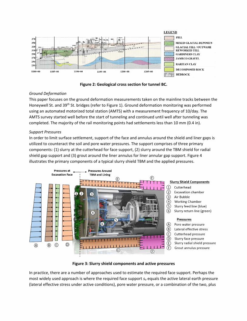
Figure 2: Geological cross section for tunnel BC.
Ground Deformation
This paper focuses on the ground deformation measurements taken on the mainline tracks between the
Honeywell St. and 39th St. bridges (refer to Figure 1). Ground deformation monitoring was performed
using an automated motorized total station (AMTS) with a measurement frequency of 10/day. The
AMTS survey started well before the start of tunneling and continued until well after tunneling was
completed. The majority of the rail monitoring points had settlements less than 10 mm (0.4 in).
Support Pressures
In order to limit surface settlement, support of the face and annulus around the shield and liner gaps is
utilized to counteract the soil and pore water pressures. The support comprises of three primary
components: (1) slurry at the cutterhead for face support, (2) slurry around the TBM shield for radial
shield gap support and (3) grout around the liner annulus for liner annular gap support. Figure 4
illustrates the primary components of a typical slurry shield TBM and the applied pressures.
Figure 3: Slurry shield components and active pressures
In practice, there are a number of approaches used to estimate the required face support. Perhaps the
most widely used approach is where the required face support sa equals the active lateral earth pressure
(lateral effective stress under active conditions), pore water pressure, or a combination of the two, plus
a nominal safety margin. An often quoted rule of thumb for the support pressure at the crown is (COB
1996):
𝑠𝑎 = 𝐾𝑎𝜎𝑣′ + 𝑝 + 20 kPa (1)
In actuality, the face support employed varies from one project to the next and is generally based on
previous experience of the contractor. For example, Table 1 lists the support pressure used in several
Japanese slurry TBM tunneling projects. It is evident that the parameters used for estimating the
necessary support pressure can be substantially different between projects.
Table 1: Support pressure used in several Japanese slurry TBM tunneling projects (Kanayasu et. al.
1995)
D [m] Soil type Support pressure used
6.63 gravel water pressure + 10-20kPa
7.04 cohesive soil earth pressure at rest
6.84 soft cohesive soil, diluvial sandy soil
active earth pressure + water pressure + fluctuating pressure (~ 20kPa)
7.45 sandy soil, cohesive
soil, gravel water pressure + 30kPa
10 sandy soil, cohesive
soil, gravel water pressure + 40-80kPa
7.45 sandy soil loose earth pressure + water pressure + fluctuating
pressure
10.58 sandy soil, cohesive
soil active earth pressure + water pressure + fluctuating
pressure (20kPa)
7.25 sandy soil, gravel, soft
cohesive soil water pressure + 30kPa
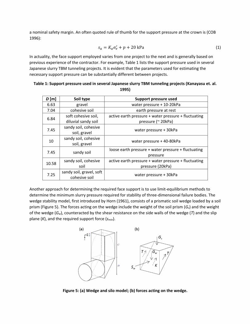
Another approach for determining the required face support is to use limit-equilibrium methods to
determine the minimum slurry pressure required for stability of three-dimensional failure bodies. The
wedge stability model, first introduced by Horn (1961), consists of a prismatic soil wedge loaded by a soil
prism (Figure 5). The forces acting on the wedge include the weight of the soil prism (Gs) and the weight
of the wedge (Gw), counteracted by the shear resistance on the side walls of the wedge (T) and the slip
plane (K), and the required support force (smin).
Figure 5: (a) Wedge and silo model; (b) forces acting on the wedge.
According to the Janssen/Terzaghi silo theory, the vertical effective stress acting on the top of the sliding
wedge is reduced by the shear stresses acting on the sliding surface of the soil prism, often referred to
as ‘soil arching.’ The wedge stability model has been further developed to incorporate different soil
layers above the TBM (Jancsecz & Steiner, 1994) and at the tunnel face (Broere, 1998). See Broere
(2001) for a comprehensive overview of the wedge stability method. The limit-equilibrium model
defines the minimum required support pressure or force at failure (FS = 1). It is common practice to
reduce the shear strength of the soil by a safety factor to provide a more conservative estimate of the
slurry face pressure. In this study, the friction angle 𝜑′ was reduced by a factor of 1.5.
When tunneling in coarse-grained, more permeable soils, consideration must be given to the reduction
in effective slurry face support as a result of slurry infiltration. Neglecting the variation in penetration
distance e over the tunnel face, Anagnostou & Kovari (1994) derived the following expression for the
reduced effective slurry support:
𝑝𝑆𝐿
𝑝𝑆𝐿(𝑂)= 1 −
𝑒
2𝐷𝑡𝑎𝑛𝜃 if 𝑒 < 𝐷𝑡𝑎𝑛𝜃 (2)
𝑝𝑆𝐿
𝑝𝑆𝐿(𝑂)=
𝐷𝑡𝑎𝑛𝜃
2𝑒 if 𝑒 > 𝐷𝑡𝑎𝑛𝜃 (3)
where pSL is the reduced support force, pSL(o) is the support force at e = 0, D is the cutterhead diameter
and 𝜃 is the angle of slip between the horizontal and the wedge plane.
In the East Side Access Queens bored tunnels project, the CQ031 contractor determined the required
face support pressure based on the Leca/Dormieux method using a safety factor of 2.0, and estimated
settlements were derived from the convergence-confinement method. This analysis determined a
baseline for the minimum pressure required to maintain face stability and a maximum allowable
pressure to safeguard against blowout. Both settlement and face pressure were optimized together, but
keeping desired minimum settlement criteria a priority. Overall, face pressure was increased as
necessary without reaching the blow out maximum pressure. Using varied sections along the
combination of the tunnel alignments, a series of face pressures and settlements were established and
then interpolated to provide the proper face pressure with respect to tunnel chainage. The face
pressure criteria was then finalized to values achievable by the TBM.
In addition to the face stability, support against collapse and significant deformation of the radial shield
and liner annular gaps must also be achieved to limit ground deformation. To prevent deformation of
the cavity at the crown, the slurry and grout support pressures should match the vertical total stress at
the crown. The vertical stress will not be geostatic, however, as soil arching does occur. On the other
hand, in the case of the slurry support in the radial shield gap, the pressure should not exceed the
vertical total stress to prevent a blow-out situation. The radial shield slurry pressure is hydraulically
linked to the slurry face pressure, which requires a unique balance between face and radial shield
support pressure to achieve stability against both collapse and blow-out.
RESULTS
Stability of the face was assessed using two methods for determining the minimum support pressure (1)
‘rule of thumb’ as provided in Equation 1 (sa) and (2) wedge stability analysis (sw) using a factor of safety
= 1.5. Stability at the crown around the shield and liner was assessed using both the geostatic vertical
surcharge (𝜎𝑣) and the reduced vertical surcharge according to the Janssen/Terzaghi silo theory (𝜎𝑣(𝑠𝑖𝑙𝑜))
at the crown.
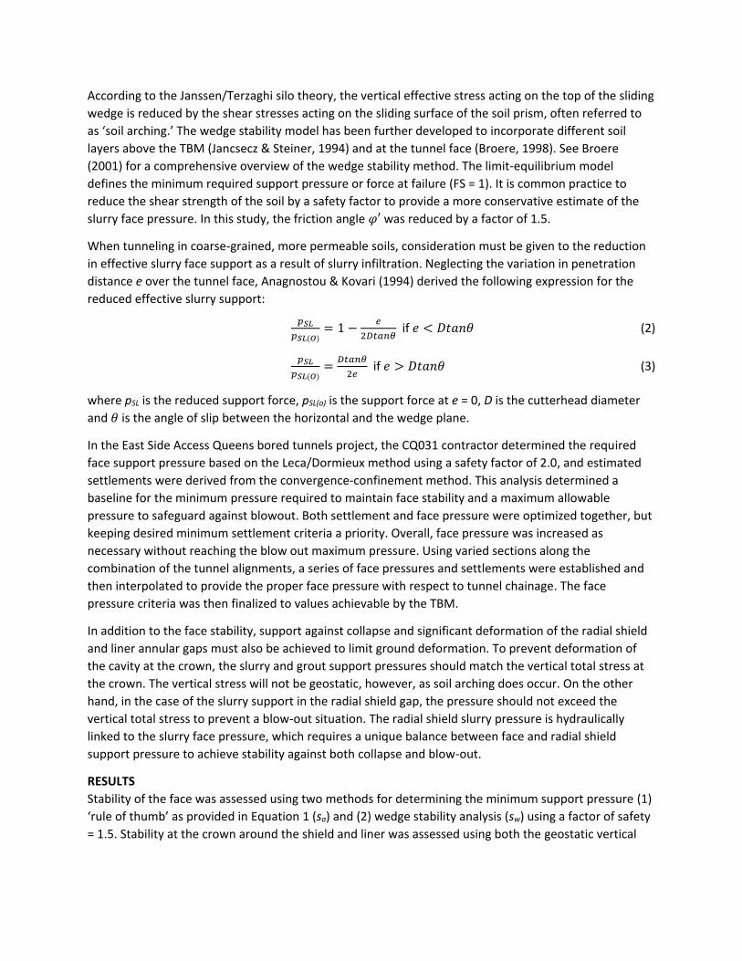
Face Stability
Figure 6 presents the face pressure results (reported at the springline) for tunnel BC. Data for the first
200 ft of the alignment is generally unreliable and has been omitted from the results. The active slurry
pressure (pSL) was measured using pressure sensors in the excavation chamber, and assumed that the
pressure of the slurry support in front of the cutterhead is the same as the pressure in the excavation
chamber, a reasonable approximation (Bezuijen and Talmon, 2014). The reduction in effective face
support resulting from slurry infiltration was also considered, although the penetration depth was found
to be minimal and only resulted in a maximum pressure reduction of 5%. The total geostatic vertical
stress (𝜎𝑣) at the springline is also presented to assess the potential for blow-out.
Figure 6: Face support and minimum requirement for stability at springline (top plot); pressure ratios
(bottom plot) - tunnel BC
For tunnel BC, the face support pSL was approximately 150 kPa (1.5 bar) at the beginning of the drive and
gradually reduced to 95 kPa by the end of the drive. pSL was found to be slightly greater than the rule of
thumb (sa) for the first 600 ft shown (average pSL/sa = 1.2) and then essentially equal to sa for the next 600
ft of the drive. For the final 800 ft of the drive, pSL was significantly greater than sa as pSL/sa gradually
approached above 2.0 by the end of the drive. pSL was 1.3-3.0 times greater than sw for the first 1400 ft
shown, and over 3.0 times greater for the last 600 ft of the drive. pSL always remained considerably below
𝜎𝑣 to prevent blowout. It can also be observed that pSL was equal to or greater than the required design
support pressures from the Leca/Dormieux method (sL/D).
One important observation from Figure 6 is that the two methods for estimating face support produce
substantially different results. Using the wedge model with a safety factor of 1.5 yields a considerably
lower minimum support pressure (15-55%) than the rule of thumb approach, which includes a safety
margin of 20 kPa. Note, without the 20 kPa safety margin, several sections of the alignment would
demonstrate that psl is less than sa. For the wedge model, if one reduced 𝜑′ such that psl/sw = 1, the
safety factor would increase to 2.5. Lastly, it is fairly well understood that arching exists above the crown
when C/D > 2-3, however, full overburden is assumed in the ‘rule of thumb’ method.
These differences highlight the confusion and uncertainty often expressed in the industry today over
which method should be used to determine the minimum support pressure. While the ‘rule of thumb’
approach provides a conservative support pressure for face stability, this support pressure could be too
high such that it overcomes the reduced vertical surcharge from arching that a blow-out can occur.
Conversely, while it’s understood that arching exists, the mechanics of arching are not fully understood
causing it to often be neglected from the calculations. In practice, a great value is placed in the
experience of the TBM operator, especially in slurry TBMs. The ability to fine tune the face pressure
based on the readouts from the TBM sensors while interpreting the data from the ground deformation
monitoring is key to a successful operation. To this day, contractors and TBM operators continue to
debate which approach is appropriate.
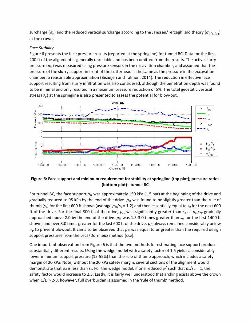
Annulus Stability
Figure 7 presents the gap pressure results for tunnel BC acting at the crown. The slurry pressure
supporting the radial shield gap (pSL) was interpolated from the pressure measurements in the
excavation chamber. It is assumed that the slurry pressure in the radial shield gap follows the same
gradient as the slurry in the excavation chamber. The grout pressure supporting the liner annulus gap at
the crown (pG) was interpolated from the measured grout injection pressure. The potential for blow-out
due to the slurry pressure was also assessed.
Figure 7: Slurry and grout pressures compared with vertical surcharge at crown (top plot); pressure
ratios (bottom plot) – Tunnel BC
With regards to stability of the radial shield gap, pSL was found to be greater than 𝜎𝑣(𝑠𝑖𝑙𝑜) and generally
equal to 𝜎𝑣 for the first 500 ft of the alignment shown. Between chainage 1192+00 and 1201+00,
however, pSL was less than 𝜎𝑣 and 𝜎𝑣(𝑠𝑖𝑙𝑜) (average pSL/𝜎𝑣 FS = 0.53; pSL/𝜎𝑣(𝑠𝑖𝑙𝑜) FS = 0.71). This section of
the alignment is beneath the mainline tracks and AMTS monitoring zone and provides a stong case for
the slight settlement observed. Convergence of the soil around the radial shield gap would be limited,
however, to the difference in cutting diameter to tail shield diameter (50 mm for the TBM used on this
project).
Concerning the stability of the liner annulus gap, pG consistently exceeded 𝜎𝑣 and 𝜎𝑣(𝑠𝑖𝑙𝑜), indicating that
stability at the crown of the liner annulus was well-achieved. Since the grout was mixed with an
accelerant for rapid curing, blow-out due the high grout pressures was not a concern and did not occur.
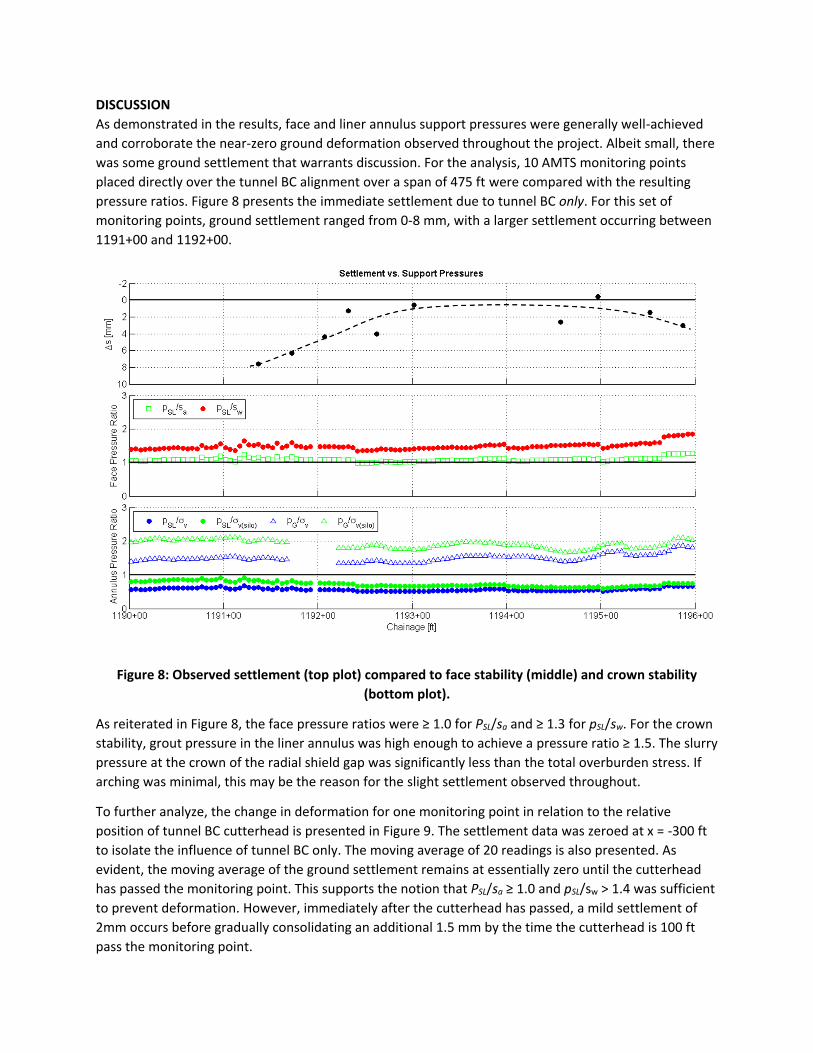
DISCUSSION
As demonstrated in the results, face and liner annulus support pressures were generally well-achieved
and corroborate the near-zero ground deformation observed throughout the project. Albeit small, there
was some ground settlement that warrants discussion. For the analysis, 10 AMTS monitoring points
placed directly over the tunnel BC alignment over a span of 475 ft were compared with the resulting
pressure ratios. Figure 8 presents the immediate settlement due to tunnel BC only. For this set of
monitoring points, ground settlement ranged from 0-8 mm, with a larger settlement occurring between
1191+00 and 1192+00.
Figure 8: Observed settlement (top plot) compared to face stability (middle) and crown stability
(bottom plot).
As reiterated in Figure 8, the face pressure ratios were ≥ 1.0 for PSL/sa and ≥ 1.3 for pSL/sw. For the crown
stability, grout pressure in the liner annulus was high enough to achieve a pressure ratio ≥ 1.5. The slurry
pressure at the crown of the radial shield gap was significantly less than the total overburden stress. If
arching was minimal, this may be the reason for the slight settlement observed throughout.
To further analyze, the change in deformation for one monitoring point in relation to the relative
position of tunnel BC cutterhead is presented in Figure 9. The settlement data was zeroed at x = -300 ft
to isolate the influence of tunnel BC only. The moving average of 20 readings is also presented. As
evident, the moving average of the ground settlement remains at essentially zero until the cutterhead
has passed the monitoring point. This supports the notion that PSL/sa ≥ 1.0 and pSL/sw > 1.4 was sufficient
to prevent deformation. However, immediately after the cutterhead has passed, a mild settlement of
2mm occurs before gradually consolidating an additional 1.5 mm by the time the cutterhead is 100 ft
pass the monitoring point.
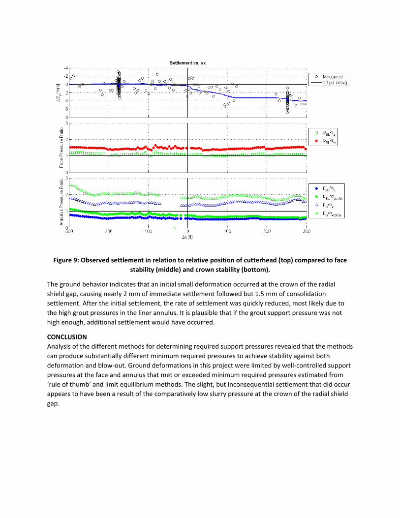
Figure 9: Observed settlement in relation to relative position of cutterhead (top) compared to face
stability (middle) and crown stability (bottom).
The ground behavior indicates that an initial small deformation occurred at the crown of the radial
shield gap, causing nearly 2 mm of immediate settlement followed but 1.5 mm of consolidation
settlement. After the initial settlement, the rate of settlement was quickly reduced, most likely due to
the high grout pressures in the liner annulus. It is plausible that if the grout support pressure was not
high enough, additional settlement would have occurred.
CONCLUSION
Analysis of the different methods for determining required support pressures revealed that the methods
can produce substantially different minimum required pressures to achieve stability against both
deformation and blow-out. Ground deformations in this project were limited by well-controlled support
pressures at the face and annulus that met or exceeded minimum required pressures estimated from
‘rule of thumb’ and limit equilibrium methods. The slight, but inconsequential settlement that did occur
appears to have been a result of the comparatively low slurry pressure at the crown of the radial shield
gap.
REFERENCES
Anagnostou, G. and Kovari, K. (1994) “The Face Stability of Slurry-shield-driven Tunnels.” Tunneling and
Underground Space Technology, Vol. 9, No. 2, Great Brittan, pp. 165-174.
Bezuijen, A. and Talmon, A.M. (2014) “Soil pressures at the cutting wheel and the pressure bulkhead of
an EPB-shield.” Geotechnical Aspects of Underground Construction in Soft Ground. Kim & Ban (eds.).
Seoul, Korea, pp. 523-529.
Broere, W. (1998) “Face Stability Calculation for a Slurry Shield in Heterogeneous Soft Soils.” Tunnels
and Metropolises, Nego, Jr. & Ferreira (eds.). Sao Paolo, Brazil, pp. 215-218.
Broere, W. (2001) Tunnel Face Stability & New CPT Applications. PhD thesis, Delft University of
Technology, Delft, The Netherlands.
COB Commissie L510 (1996). Inventarisatie ontwerpmethoden boortunnels voor weg- en
railverbindingen. Technical Report L510-01, COB.
Horn, N. (1961) “Horizontaler Erddruck auf senkrechte Abschlussflächen von Tunnelröhren.” In Landeskonferenz der Ungarischen Tiefbauindustrie, pp. 7–16.
Jancsecz, S. and Steiner, W. (1994) “Face support for a large mix-shield in heterogeneous ground
conditions.” Tunneling ’94. London, Institution of Mining and Metallurgy.
Kanayasu, S., Kubota, I. and Shikibu, N. (1995) “Stability of face during shield tunneling - A survey of
Japanese shield tunneling.” Underground Construction in Soft Ground, Fujita & Kusakabe (eds.).
Rotterdam, Balkema.
Mair, R.J.; Taylor, R.N.; Burland, J.B. (1996) “Prediction of ground movements and assessment of risk of
building damage due to bored tunneling.” Geotechnical Aspects of Underground Construction in Soft
Ground, Mair & Taylor (eds.). Rotterdam, Balkema-Verlag.
Prantil, E., Perrone, F., Smith, D. and Wehrli, J. (2014) “Pushing the Limit - Shallow Cover Slurry TBM
Mining Between Active Commuter Rail Tracks.” North American Tunneling Conference 2014 Proc., Los
Angeles, CA., pp. 1,133-1,142.
Robinson, B. and Wehrli, J.M. (2013a) “East Side Access - Queens bored tunnels case study.” Proc. 21st
Rapid Excavation and Tunneling Conference, Washington, D.C., pp. 1,014-1,141.
Robinson, B. and Wehrli, J.M. (2013b) “East Side Access - Queens bored tunnels engineering challenges.”
Proc. 21st Rapid Excavation and Tunneling Conference, Washington, D.C., pp. 1,086-1,118.