Embed Size (px)
Citation preview
EVALUATION OF SOLDER PASTES FOR
HIGH RELIABILITY APPLICATIONS
Scott J. Anson Ph.D., PE
LeTourneau University
Longview, TX, USA
Michael McLaughlin and Abner Argueta
IEC Electronics Corporation
Newark NY, USA
[email protected]; [email protected]
ABSTRACT
Solder paste is the most important material in Surface
Mount Technology (SMT) assembly, and contract
manufacturers of high reliability electronics face the
simultaneous challenges of multisite operations combined
with mission critical customer applications. It is essential to
select a solder paste that performs at a high level under
optimum conditions and also gives stable performance
under suboptimal conditions, such as common
environmental and manufacturing time fluctuations. This
study examined 63Sn/37Pb solder paste alloy with both
63Sn/37Pb and 96.5/3.0Ag/0.5Sn (SAC305) lead free
components in mixed alloy reflow. Both water soluble and
no-clean chemistries were evaluated. A design of
experiments (DOE) approach was employed to examine
solder balling and slump resistance. Additional experiments
examined print quality utilizing automated Solder Paste
Inspection (SPI) in terms of bridge resistance, CSP and
0201 insufficient resistance, and response to a 45 minute
print pause. Assemblies were also built to check for defects,
joint quality, and voiding. The result is a holistic approach
to solder paste testing that includes weighting of numerous
factors to assess solder paste performance and robustness to
external variation such as humidity and exposure time.
Key Words: Solder paste, mixed alloy, multifactor
evaluation
INTRODUCTION
Stencil printing has long been established as the most
important process in all of surface mount technology (SMT)
with up to 52-71% of defects attributed to this one process
step. 1, 2
Similarly, solder paste is most important material
selection in all of SMT assembly. 3 Solder paste powder
size distribution and flux chemistry determine the
following: 1) Acceptable range of reflow profiles; 2) Ability
to print fine pitch apertures, 3) Ability to resist time and
humidity dependent slump, 4) Ability to resist solder ball
formation, 5) Small aperture release both at time zero and
after a pause in printing, 6) Solder joint wetting and
appearance, and 7) Void formation. In order for a solder
paste to be a manufacturing relevant product, the
performance must be adequate in each category with a high
average performance, such that it is best overall. For
example a solder paste that excels in most areas but is very
sensitive to humidity induced solder balls, would not be
practical. It is possible for the best overall solder paste not
have the best performance in any test criteria. The result is
that evaluation of solder paste is a complex multifactor
problem.
High reliability electronics are experiencing a size and
weight reduction in products ranging from soldier carried
military accessories to biomedical implantable devices.
This size and weight reduction has caused a surge in fine
pitch Chip Scale Packages (CSP) such as 16 mil (0.4 mm)
pitch as well as 0201 and 01005 discretes. In order to
accommodate these small size challenges, the solder paste
evaluation considered smaller Type 4 particle sizes in
addition to traditional Type 3 particle sizes. The high
reliability scenario provides a Reduction of Hazardous
Substances (ROHS) legislation exemption and allows for
63Sn/37Pb solder paste to be used for enhanced reliability
reasons. The combination of 63Sn/37Pb and Type 4 particle
size is uncommon for the paste manufacturers as most Type
4 paste is used on fine pitch consumer products, which are
lead free for ROHS compliance. Historically high reliability
electronics have been larger pitches such that Type 3 solder
paste particle size was viable. This issue gives rise to
potential supply chain delays as the Type 4 particle size and
63Sn/37Pb solder paste is often blended upon ordering.
Mitigation strategies were implemented to prevent a
material shortage.
RESEARCH METHODOLOGY
The study consisted of a series of experiments that were
conducted on six water soluble and seven no-clean solder
pastes as shown in Table 1. Table 2 shows the experiment
overview. The work reported herein will use the water
soluble samples for explanation and any no-clean variations
will be pointed out where they occur.
As originally published in the SMTA Proceedings.
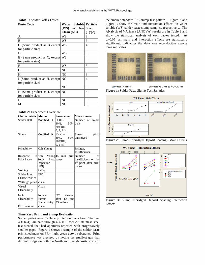
Table 1: Solder Pastes Tested
Paste Code Water Soluble
(WS) or No-
Clean (NC)
Particle
Size
(Type)
A WS 3
B WS 3
C (Same product as B except
for particle size)
WS 4
D WS 3
E (Same product as C, except
for particle size)
WS 4
F WS 3
G NC 3
H NC 3
I (Same product as H, except
for particle size)
NC 4
J NC 3
K (Same product as J, except
for particle size)
NC 4
L NC 3
M NC 3
Table 2: Experiment Overview
Characteristic Method Parameters Measurement
Solder Ball Modified IPC DOE –
30%, 50%,
70%RH,
0, 2, 4 hr.
Number of solder
balls
Slump Modified IPC DOE –
30%, 50%,
70%RH,
0, 2 hr.
Finest pitch
unbridged
Printability Koh Young Bridges,
Insufficients
Response to
Print Pause
Koh Young
Solder Paste
Inspection
(SPI)
45 min print
pause
Number of
insufficients on the
1st print after print
pause
Voiding X-Ray
Solder Joint
Characteristics
IPC
Wetting/Spread Visual
Visual
Cleanability
Visual
Ionic
Cleanability
Solvent
Extract
Conductivity
NC cleaned
after 1X and
3X reflow
Flux Residue Visual
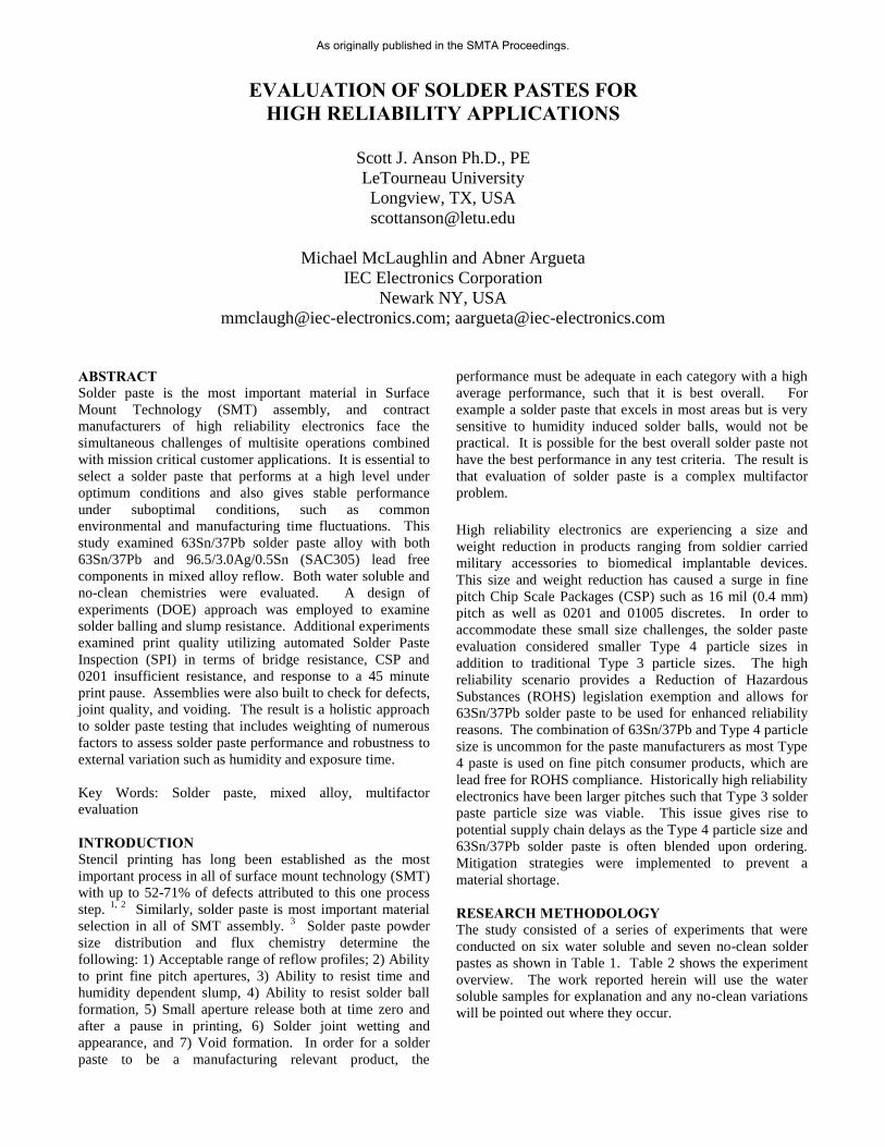
Time Zero Print and Slump Evaluation
Solder pastes were machine printed on blank Fire Retardant
4 (FR-4) laminate through a 4 mil laser cut stainless steel
test stencil that had apertures repeated with progressively
smaller gaps. Figure 1 shows a sample of the solder paste
print specimens on FR-4 light green epoxy substrates. Print
performance was assessed by noting the smallest gap that
did not bridge on both the North and East deposits strips of
the smaller standard IPC slump test pattern. Figure 2 and
Figure 3 show the main and interaction effects on water
soluble (WS) solder paste slump samples, respectively. The
ANalysis of VAriance (ANOVA) results are in Table 2 and
show the statistical analysis of each factor tested. At
, all main and interaction effects are statistically
significant, indicating the data was reproducible among
three replicates.
Figure 1: Solder Paste Slump Test Samples
Figure 2: Slump/Unbridged Deposit Spacing - Main Effects
Figure 3: Slump/Unbridged Deposit Spacing Interaction
Effects
As originally published in the SMTA Proceedings.
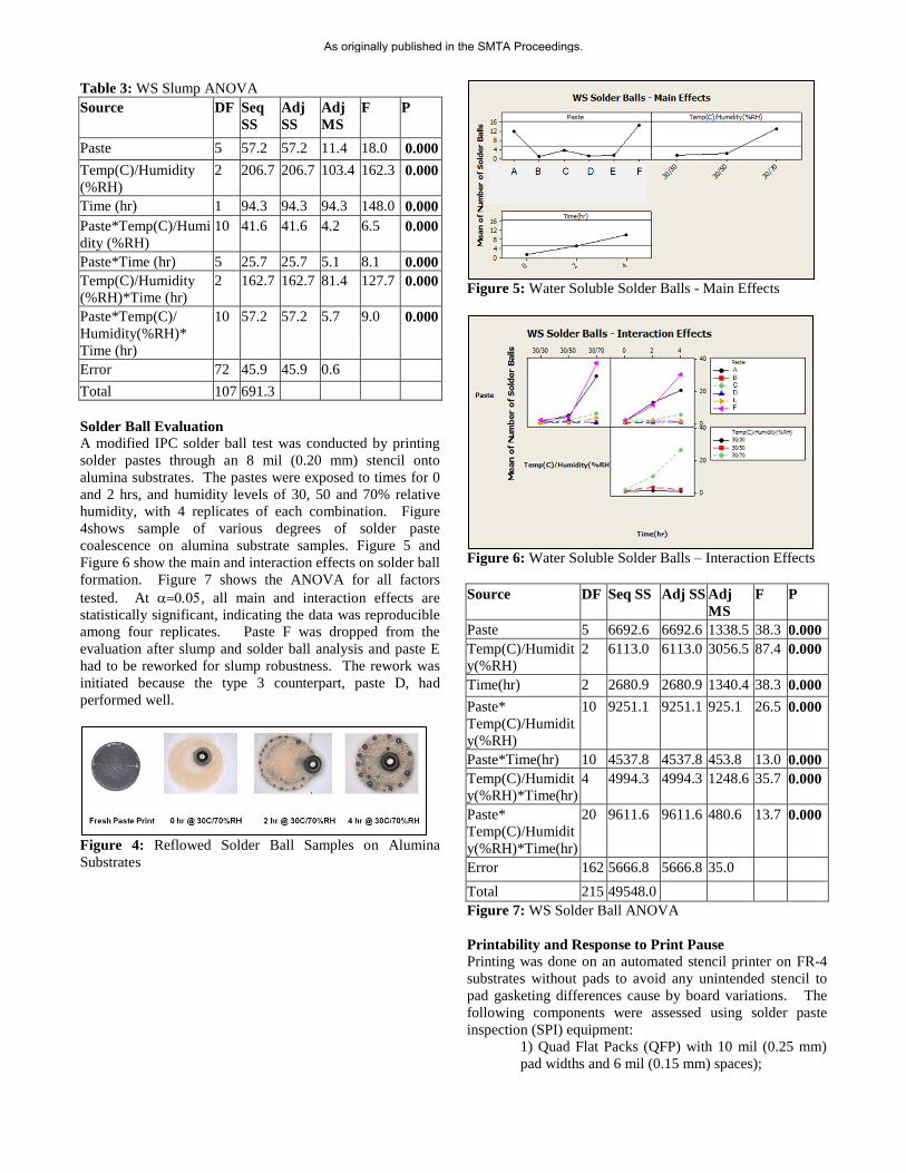
Table 3: WS Slump ANOVA
Source DF Seq
SS
Adj
SS
Adj
MS
F P
Paste 5 57.2 57.2 11.4 18.0 0.000
Temp(C)/Humidity
(%RH)
2 206.7 206.7 103.4 162.3 0.000
Time (hr) 1 94.3 94.3 94.3 148.0 0.000
Paste*Temp(C)/Humi
dity (%RH)
10 41.6 41.6 4.2 6.5 0.000
Paste*Time (hr) 5 25.7 25.7 5.1 8.1 0.000
Temp(C)/Humidity
(%RH)*Time (hr)
2 162.7 162.7 81.4 127.7 0.000
Paste*Temp(C)/
Humidity(%RH)*
Time (hr)
10 57.2 57.2 5.7 9.0 0.000
Error 72 45.9 45.9 0.6
Total 107 691.3
Solder Ball Evaluation
A modified IPC solder ball test was conducted by printing
solder pastes through an 8 mil (0.20 mm) stencil onto
alumina substrates. The pastes were exposed to times for 0
and 2 hrs, and humidity levels of 30, 50 and 70% relative
humidity, with 4 replicates of each combination. Figure
4shows sample of various degrees of solder paste
coalescence on alumina substrate samples. Figure 5 and
Figure 6 show the main and interaction effects on solder ball
formation. Figure 7 shows the ANOVA for all factors
tested. At , all main and interaction effects are
statistically significant, indicating the data was reproducible
among four replicates. Paste F was dropped from the
evaluation after slump and solder ball analysis and paste E
had to be reworked for slump robustness. The rework was
initiated because the type 3 counterpart, paste D, had
performed well.
Figure 4: Reflowed Solder Ball Samples on Alumina
Substrates
Figure 5: Water Soluble Solder Balls - Main Effects
Figure 6: Water Soluble Solder Balls – Interaction Effects
Source DF Seq SS Adj SS Adj
MS
F P
Paste 5 6692.6 6692.6 1338.5 38.3 0.000
Temp(C)/Humidit
y(%RH)
2 6113.0 6113.0 3056.5 87.4 0.000
Time(hr) 2 2680.9 2680.9 1340.4 38.3 0.000
Paste*
Temp(C)/Humidit
y(%RH)
10 9251.1 9251.1 925.1 26.5 0.000
Paste*Time(hr) 10 4537.8 4537.8 453.8 13.0 0.000
Temp(C)/Humidit
y(%RH)*Time(hr)
4 4994.3 4994.3 1248.6 35.7 0.000
Paste*
Temp(C)/Humidit
y(%RH)*Time(hr)
20 9611.6 9611.6 480.6 13.7 0.000
Error 162 5666.8 5666.8 35.0
Total 215 49548.0
Figure 7: WS Solder Ball ANOVA
Printability and Response to Print Pause
Printing was done on an automated stencil printer on FR-4
substrates without pads to avoid any unintended stencil to
pad gasketing differences cause by board variations. The
following components were assessed using solder paste
inspection (SPI) equipment:
1) Quad Flat Packs (QFP) with 10 mil (0.25 mm)
pad widths and 6 mil (0.15 mm) spaces);
As originally published in the SMTA Proceedings.
2) Chip Scale Packages (CSP) with 11 mil (0.28
mm) diameter with 9 mil (0.23mm) spaces; and
3) 0201s with 11 mil (0.28mm) X 15 mil (0.38mm)
apertures.
The QFP pad was deliberately extra difficult to print to
enable use as a strong indicator because no defects occurred
on a typical QFP with 8 mil (0.20 mm) width pads and
spaces.
Five printed wiring boards (PWB) were printed back to back
(less than one minute delay) followed by a 45 minute print
pause and then boards 6 through 10 were printed back to
back. The purpose of the 45 minute pause was to simulate a
line delay similar to a lunch and production meeting. While
stencils are washed after breaks, measurement of response
to print pause was used to assess production robustness.
Figure 8 shows the print defects on PWBS 1-5. Again note
the QFP bridges are extra high due to the aggressive 10 mil
(0.25 mm) pads on 6 mil (0.15 mm) spaces. On typical 8
mil (0.20 mm) pads and spaces no bridges occurred so the
10 mil (0.25 mm) pad and 6 mil (0.15 mm) space was used
as a strong indicator of print performance. Comparing
Figure 8 and Figure 9 shows the change in print
performance after a 45 minute print pause and pastes B and
C show marked increase in CSP aperture clogging.
Figure 8: Prints 1-5 for Each Paste – No Pause
Figure 9: Prints 6-10 for Each Paste – 45 Minute Pause
Between Prints 5 and 6
Joint Visual Characteristics
Test boards were built with components and joints as
described in Table 3. Visual inspection was done on the test
boards to IPC-610A, class 3 standards. Figure 9 shows QFP
208 joints with good wetting and joint shape on each
sample. Figure 9 shows 0201 solder joints and reveals a
mottled appearance on pastes A, B, and C which is also
shown in the close up image of A. The spots are a surface
phenomenon on the solder joint and are not uncoalesced
solder paste spheres, but could be the oxide residue from
individual solder spheres. This could possibly indicate the
flux activity of the 63Sn/37Pb solder paste was being
consumed on small deposits (0201) at elevated mixed alloy
reflow temperatures. Each PWB built also had a D-PAK
window pane stencil design and the spread of the solder on
the ground plane was used to assess wetting of each paste as
shown in Figure 10. Pastes B and C were formulated by
the same vendor and had improved solder spreading over
the other pastes. All pastes had adequate wetting as shown
on the solder joint images in Figure 8 and Figure 9.
Table 4: Test Board Components Placed
Component Type Qty
Placed
Number of
Solder Joints
CABGA208
(SAC305 Balls)
1 208
QFP208 1 208
0201 30 60
0402 34 68
0603 31 62
0805 21 42
1210 14 28
SOT-23 24 72
MLF100 1 100
PLCC68 1 68
QFP100 1 100
Total 1016
As originally published in the SMTA Proceedings.
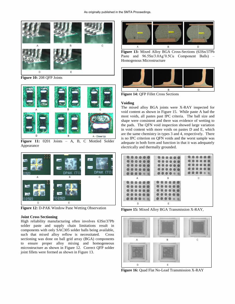
Figure 10: 208 QFP Joints
Figure 11: 0201 Joints – A, B, C Mottled Solder
Appearance
Figure 12: D-PAK Window Pane Wetting Observation
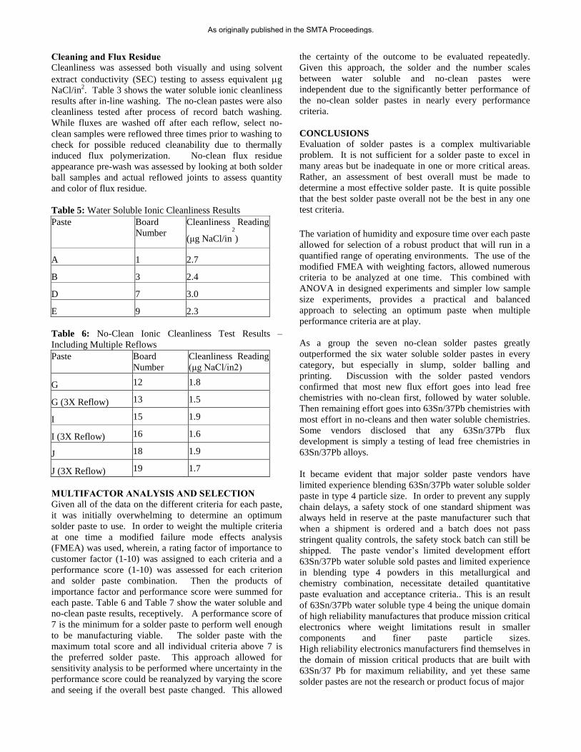
Joint Cross Sectioning
High reliability manufacturing often involves 63Sn/37Pb
solder paste and supply chain limitations result in
components with only SAC305 solder balls being available,
such that mixed alloy reflow is necessitated. Cross
sectioning was done on ball grid array (BGA) components
to ensure proper alloy mixing and homogeneous
microstructure as shown in Figure 12. Correct QFP solder
joint fillets were formed as shown in Figure 13.
Figure 13: Mixed Alloy BGA Cross-Sections (63Sn/37Pb
Paste and 96.5Sn/3.0Ag’0.5Cu Component Balls) –
Homogenous Microstructure
Figure 14: QFP Fillet Cross Sections
Voiding
The mixed alloy BGA joints were X-RAY inspected for
void content as shown in Figure 15. While paste A had the
most voids, all pastes past IPC criteria. The ball size and
shape were consistent and there was evidence of wetting to
the pads. The QFN void inspection showed large variation
in void content with more voids on pastes D and E, which
are the same chemistry in types 3 and 4, respectively. There
is no IPC criterion on QFN voids and the worst sample was
adequate in both form and function in that it was adequately
electrically and thermally grounded.
Figure 15: Mixed Alloy BGA Transmission X-RAY,
Figure 16: Quad Flat No-Lead Transmission X-RAY
As originally published in the SMTA Proceedings.
Cleaning and Flux Residue
Cleanliness was assessed both visually and using solvent
extract conductivity (SEC) testing to assess equivalent g
NaCl/in2. Table 3 shows the water soluble ionic cleanliness
results after in-line washing. The no-clean pastes were also
cleanliness tested after process of record batch washing.
While fluxes are washed off after each reflow, select no-
clean samples were reflowed three times prior to washing to
check for possible reduced cleanability due to thermally
induced flux polymerization. No-clean flux residue
appearance pre-wash was assessed by looking at both solder
ball samples and actual reflowed joints to assess quantity
and color of flux residue.
Table 5: Water Soluble Ionic Cleanliness Results
Paste Board
Number
Cleanliness Reading
(μg NaCl/in2
)
A 1 2.7
B 3 2.4
D 7 3.0
E 9 2.3
Table 6: No-Clean Ionic Cleanliness Test Results –
Including Multiple Reflows
Paste Board
Number
Cleanliness Reading
(μg NaCl/in2)
G 12 1.8
G (3X Reflow) 13 1.5
I 15 1.9
I (3X Reflow) 16 1.6
J 18 1.9
J (3X Reflow) 19 1.7
MULTIFACTOR ANALYSIS AND SELECTION
Given all of the data on the different criteria for each paste,
it was initially overwhelming to determine an optimum
solder paste to use. In order to weight the multiple criteria
at one time a modified failure mode effects analysis
(FMEA) was used, wherein, a rating factor of importance to
customer factor (1-10) was assigned to each criteria and a
performance score (1-10) was assessed for each criterion
and solder paste combination. Then the products of
importance factor and performance score were summed for
each paste. Table 6 and Table 7 show the water soluble and
no-clean paste results, receptively. A performance score of
7 is the minimum for a solder paste to perform well enough
to be manufacturing viable. The solder paste with the
maximum total score and all individual criteria above 7 is
the preferred solder paste. This approach allowed for
sensitivity analysis to be performed where uncertainty in the
performance score could be reanalyzed by varying the score
and seeing if the overall best paste changed. This allowed
the certainty of the outcome to be evaluated repeatedly.
Given this approach, the solder and the number scales
between water soluble and no-clean pastes were
independent due to the significantly better performance of
the no-clean solder pastes in nearly every performance
criteria.
CONCLUSIONS
Evaluation of solder pastes is a complex multivariable
problem. It is not sufficient for a solder paste to excel in
many areas but be inadequate in one or more critical areas.
Rather, an assessment of best overall must be made to
determine a most effective solder paste. It is quite possible
that the best solder paste overall not be the best in any one
test criteria.
The variation of humidity and exposure time over each paste
allowed for selection of a robust product that will run in a
quantified range of operating environments. The use of the
modified FMEA with weighting factors, allowed numerous
criteria to be analyzed at one time. This combined with
ANOVA in designed experiments and simpler low sample
size experiments, provides a practical and balanced
approach to selecting an optimum paste when multiple
performance criteria are at play.
As a group the seven no-clean solder pastes greatly
outperformed the six water soluble solder pastes in every
category, but especially in slump, solder balling and
printing. Discussion with the solder pasted vendors
confirmed that most new flux effort goes into lead free
chemistries with no-clean first, followed by water soluble.
Then remaining effort goes into 63Sn/37Pb chemistries with
most effort in no-cleans and then water soluble chemistries.
Some vendors disclosed that any 63Sn/37Pb flux
development is simply a testing of lead free chemistries in
63Sn/37Pb alloys.
It became evident that major solder paste vendors have
limited experience blending 63Sn/37Pb water soluble solder
paste in type 4 particle size. In order to prevent any supply
chain delays, a safety stock of one standard shipment was
always held in reserve at the paste manufacturer such that
when a shipment is ordered and a batch does not pass
stringent quality controls, the safety stock batch can still be
shipped. The paste vendor’s limited development effort
63Sn/37Pb water soluble sold pastes and limited experience
in blending type 4 powders in this metallurgical and
chemistry combination, necessitate detailed quantitative
paste evaluation and acceptance criteria.. This is an result
of 63Sn/37Pb water soluble type 4 being the unique domain
of high reliability manufactures that produce mission critical
electronics where weight limitations result in smaller
components and finer paste particle sizes.
High reliability electronics manufacturers find themselves in
the domain of mission critical products that are built with
63Sn/37 Pb for maximum reliability, and yet these same
solder pastes are not the research or product focus of major
As originally published in the SMTA Proceedings.
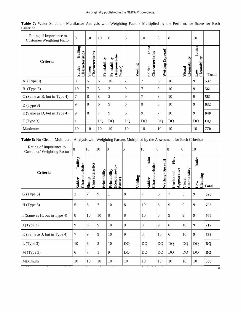
Table 7: Water Soluble - Multifactor Analysis with Weighting Factors Multiplied by the Performance Score for Each
Criterion
Rating of Importance to
Customer/Weighting Factor 8 10 10 8 5 10 8 8 10
Criteria
So
lder
B
all
ing
Ch
ara
cter
isti
cs
Slu
mp
Ch
ara
cter
isti
cs
Pri
nta
bil
ity
Pri
nta
bil
ity
(Res
po
nse
-to
-
Pa
use
)
Vo
idin
g
So
lder
J
oin
t
Ch
ara
cter
isti
cs
Wet
tin
g (
Sp
rea
d)
Vis
ua
l
Cle
an
ab
ilit
y
Lo
w
Io
nic
s
Cle
an
ab
ilit
y
Total
A (Type 3) 3 5 6 10 7 7 6 10 9 537
B (Type 3) 10 7 3 3 9 7 9 10 9 561
C (Same as B, but in Type 4) 7 8 8 2 9 7 8 10 9 581
D (Type 3) 9 9 6 9 6 9 6 10 9 632
E (Same as D, but in Type 4) 9 8 7 9 6 9 7 10 9 640
F (Type 3) 1 1 DQ DQ DQ DQ DQ DQ DQ DQ
Maximum 10 10 10 10 10 10 10 10 10 770
Table 8: No-Clean - Multifactor Analysis with Weighting Factors Multiplied by the Assessment for Each Criterion
Rating of Importance to
Customer/ Weighting Factor 8 10 10 8 5 10 8 8 8 10
Criteria
So
lder
B
all
ing
Ch
ara
cter
isti
cs
Slu
mp
Ch
ara
cter
isti
cs
Pri
nta
bil
ity
Pri
nta
bil
ity
(Res
po
nse
-to
-
Pa
use
)
Vo
idin
g
So
lder
J
oin
t
Ch
ara
cter
isti
cs
Wet
tin
g (
Sp
rea
d)
Un
clea
ned
F
lux
Ap
pea
ran
ce
Vis
ua
l
Cle
an
ab
ilit
y
Lo
w
Ion
ics
Cle
an
ing
Total
G (Type 3) 3 7 9 1 8 7 6 7 3 9 520
H (Type 3) 5 8 7 10 8 10 8 9 9 9 708
I (Same as H, but in Type 4) 8 10 10 8 8 10 8 9 9 9 766
J (Type 3) 9 6 9 10 9 8 9 6 10 9 717
K (Same as J, but in Type 4) 7 9 9 10 9 8 10 6 10 9 739
L (Type 3) 10 6 2 10 DQ DQ DQ DQ DQ DQ DQ
M (Type 3) 6 7 1 9 DQ DQ DQ DQ DQ DQ DQ
Maximum 10 10 10 10 10 10 10 10 10 10 850
Table 8: No-Clean - Multifactor Analysis with Weighting Factors Multiplied by the Assessment for Each Criterion
As originally published in the SMTA Proceedings.
solder paste manufactures. There seems to be a vacant
niche for a solder paste manufacturer to differentiate
themselves with a focus on 63Sn/37Pb water soluble solder
pastes in type 4 for the high reliability market sector.
ACKNOWLEDGEMENTS
Thank you to IEC management for providing an
environment that allows technical personnel a chance to
advance the process capabilities of the company. Numerous
engineers and production personnel have helped with this
project and while they are too numerable to list, their help
and support are critically appreciated. Specific thanks to
Bob Nielsen and Dr. Ron Pratt.
REFERENCES
1 C. McPhail (1996), “Screen Printing is a Science not an
Art”, Soldering and Surface Mount Technology, 8(2): p.
25-28.
2 Jianbiao, P.; Tonkay, G.L. ; Storer, R.H. ; Sallade, R.M. ;
(2004) “Critical Variables of Solder Paste Stencil Printing
for Micro-BGA and Fine-Pitch QFP”, Electronics
Packaging Manufacturing, IEEE Transactions on , Volume
27 , Issue 2, pp. 125-132. 3 Durairaj, R. ; Nguty, T.A. ; Ekere, N.N. (2001) "Critical
Factors Affecting Paste Flow During the Stencil Printing of
Solder Paste", Soldering & Surface Mount Technology, Vol.
13 Iss: 2, pp. 30-34.
As originally published in the SMTA Proceedings.


![Size Matters - The Effects of Solder Powder Size on Solder ... · Solder powder sizes are classified by type in the IPC standard J-STD-005 Requirements for Soldering Pastes [1]. Table](https://img.pdfslide.net/doc/110x75/5e7581f299edbf7be157d774/size-matters-the-effects-of-solder-powder-size-on-solder-solder-powder-sizes.jpg)