Embed Size (px)
Citation preview
TO OUR CUSTOMER:
Thank you for purchasing an EverRide Hornet Zero Turn Mower. We believe that you have exercised excellent judgment in your selection. The Hornet mower has been designed to give you many years of satisfactory service. Successful operation and long life depends on proper maintenance and correct operating techniques.
Before you received your unit, the dealer has performed a pre-delivery inspection. The dealer will discuss with you the features, operation and maintenance requirements. Your dealer will always be there to help you any time you need assistance or need equipment related to the use of your EverRide mower.
We recommend that you carefully read this entire manual before operating the unit. This operator’s manual has been printed to provide you with safe operating techniques, proper maintenance procedures, correct assembly, and parts identifi cation on your EverRide Zero Turn Mower. Keep this manual handy for future reference.
Should any assistance be needed in understanding any section of this manual, contact your EverRide products dealer.
This equipment is covered by a written warranty which will be provided to you in the pages following.
EverRide reserves the right to make changes or add improvements to its products without incurring any obligation to make such changes to products manufactured previously. EverRide, or its dealers, accept no responsibility for variations which may be evident in the actual specifi cations of its products and the statements and descriptions contained in the publication.
© 2005Auburn Consolidated Industries, Inc.
OWNER’S WARRANTY INFORMATION
This warranty applies to the original retail purchaser of the EverRide products only. The warranty period starts upon the date of the original purchase reflected on the sales invoice.
As a condition to this warranty, the owner/operator shall have read, understood and followed the operator’s manual guidelines for operations and maintenance supplied with this product, and that the product registration shall have been mailed to EverRide. Any lack of good maintenance, such as maintaining proper belt tension, tire pressures and lubrica-tion shall be reason for rejection of a warranty claim.
In the judgment of EverRide, any original part found to be defective in material, workmanship or performance, will be repaired or replaced with a new part only by an EverRide Au-thorized Servicing Dealer without charge for parts and labor based on the following terms and conditions:
Warranty Coverage:
This warranty is limited to two years from the date of pur-chase for parts and one year for labor for any EverRide product used for commercial purposes, income producing purposes or residential use. EverRide products used for rental purposes are limited to 90 days of warranty. Engine and battery warranties are provided separately by the manu-facturer of those components.
Belts, cutting blades, grass collection bags and tires are guaranteed to be free from manufacturer’s defects for the first 90 days.
The mower deck shell will be warranted from cracking as a result of defects in material or workmanship for the life of the unit.
Service parts are warranted for 90 days from the date of purchase.
What this warranty does not cover:
The expense incurred for delivering this product to the dealer and returning it after repair. The responsibility of EverRide and its servicing dealers is limited to making the required repairs. Further, no breach of warranty shall be cause for cancellation of the contract of sale.
Subsequent purchasers of the mower other than the original purchaser. This warranty is not transferable.
Product(s) that has (have) been subject to improper mainte-nance, neglect, misuse, accident, alteration, modified or op-erated in any way contrary to the instructions specified in the Operator’s Manual. Repairs made by unauthorized persons will not be covered under warranty. Damages caused by use of EverRide equipment other than for what it was designed.
Damages that are caused by unauthorized attachments, al-terations or modifications will not be covered under warranty. Any piece of equipment where the serial number has been removed or is made illegible will not be covered under war-ranty.
Wear or maintenance items (unless defective) including, but not limited to: Clutch and brake linings, light bulbs, grass bags, filters (air, fuel, oil), lubricants & coolants (unless used during an authorized repair), spark plugs, injector nozzles.
As the manufacturer of this product, EverRide reserves the right to change, modify or improve the design of any of its products without assuming any obligation to modify or up-grade any mower, previously sold or manufactured.
As stated above, all other implied warranties are limited in duration. Any such implied warranties including merchant-ability, fitness for a particular purpose, or otherwise, are dis-claimed in their entirety after the expiration of the warranty period. EverRide’s obligation to the original owner is strictly and exclusively limited to the repair or replacement of de-fective parts, and EverRide does not assume nor authorize anyone to assume for them any other obligation.
EverRide assumes no responsibility for incidental, con-sequential or other damages including, but not limited to: Transportation of the mower to an Authorized Dealer and returning it back, rental of truck or trailer for transportation, expense for gasoline, injury to property, mechanic’s travel time and mileage to perform repair(s), rental of a like prod-uct, loss of use of the EverRide product, loss of savings or revenue, loss or damage to personal property, and/or tele-phone charges.
Exclusions or limitations as stated above may not be allowed in some states. This warranty allows you specific legal rights and you may have other rights in your state.
Warranty Registration
The warranty registration form must be completed and signed by the authorized dealer and the original purchaser and returned to EverRide within ten days of the date of pur-chase. The date of purchase is considered the day the unit is delivered.
Dealer or Distributor Warranties
The selling dealer and distributor makes no warranty of their own and neither the dealer nor the distributor has any au-thority to make any representation or promise on behalf of EverRide, or to modify the terms or limitations of this war-ranty in any way.

CONTENTS - i
EverRide HornetOperator’s & Parts Manual
CONTENTSSAFETY 1
PERSONAL SAFETY INSTRUCTIONS 1SAFE OPERATING PRACTICES 1 TRAINING 1 PREPARATION 1 OPERATION 2 MAINTENANCE AND STORAGE 2EVERRIDE MOWER SAFETY 3GENERAL SAFETY RULES 3KEEP PASSENGERS OFF 4BEFORE OPERATION 4DURING OPERATION 5OPERATING ON SLOPES 6ROLL OVER PROTECTIVE STRUCTURE 6SEAT BELT USAGE 7MAINTENANCE 7FUEL SYSTEM 7HYDRAULIC SYSTEM 8BATTERY MAINTENANCE 8TIRE MAINTENANCE 9REPLACEMENT PARTS 9TRANSPORTING 9SLOPE GUIDE 10SAFETY & INSTRUCTION DECALS 12
INTRODUCTION 14IDENTIFICATION 15
MODEL/SERIAL NUMBERS 15INSTRUMENTS & CONTROLS 16
INSTRUMENT PANEL 16ELECTRIC FUEL SHUT OFF 17IGNITION SWITCH 17ENGINE THROTTLE 17CHOKE 17PTO ENGAGEMENT 17HOUR METER 17
OPERATING THE POWER UNIT 18 BREAK –IN PERIOD 18 MOUNTING AND DISMOUNTING SAFELY 18 FUEL 18 STARTING THE EVERRIDE MOWER 18 Pre Start Inspection 18 Normal Starting 19 Starting in Cold Weather 19 Jump Starting the Power Unit 19 WARMING THE ZERO TURN MOWER 20 INCREASING ACCELERATION 21 OPERATING THE EVERRIDE MOWER 21 STEERING CONTROLS 21 STOPPING THE ENGINE 22 MOVING A STALLED EVERRIDE MOWER 22

ii - CONTENTS
TOWING WITH AN EVERRIDE MOWER 22 PARKING THE POWER UNIT 22 LOADING THE MOWER 22 TRANSPORTING THE MOWER 23
OPERATING THE MOWER 24 GENERAL INFORMATION 24 OPERATING A SIDE DISCHARGE MOWER 24 TIPS FOR EFFICIENT MOWING 24 CUTTING HEIGHTS 25 ADJUSTING THE MOWER HEIGHT OF CUT 25 ANTI-SCALP WHEEL ADJUSTMENT 25 UNEVEN TERRAIN 26 GRASS DISCHARGE 26
PARTS 27LUBRICATION AND MAINTENANCE 28
SPECIFICATIONS AND CAPACITIES 28 LUBRICATION/FILL POINTS 29 PERIODIC MAINTENANCE SCHEDULE 30 AVOID FUMES 31 SERVICE ACCESS 31 ENGINE OIL LEVEL 31 CHANGING THE ENGINE OIL 31 OIL FILTER CHANGE 32 HYDROSTATIC MAINTENANCE 32 CHANGING THE HYDRAULIC FLUID 33 BLEEDING THE HYDRAULICS 33 CHECKING THE HYDRAULIC HOSES 34 BATTERY MAINTENANCE 34 INSTALLING THE BATTERY 34 REMOVING THE BATTERY 34 CHARGING THE BATTERY 35 CLEANING THE BATTERY AND TERMINALS 35 REPLACING THE FUSES 35 SAFETY CHECKS 35 CHECKING THE KILL CIRCUITS 36 ELECTRIC CLUTCH STOP CHECK 36 NEUTRAL ADJUSTMENT 36 SERVICING THE CASTER WHEEL ROLLER BEARINGS 37 SERVICING THE CASTER PIVOT BEARINGS 37 LEVELING THE DECK 38 SYNCHRONIZING HEIGHT OF CUT 38 DRIVE ADJUSTMENTS 39 ENGINE AIR CLEANER SERVICE 39 FUEL SYSTEM SERVICE 40 CHECK VALVE SERVICE 41 SPARK PLUG SERVICE 41 COOLING SYSTEM CLEANING 42 SEASONAL STORAGE 42 FUEL SYSTEM DRAINING 42 TIRE AND WHEEL MAINTENANCE 43 BLADE MAINTENANCE 44 CLEANING GRASS BUILDUP FROM DECK 45 BELT REPLACEMENT 45

CONTENTS - iii
DECK BELT REPLACEMENT 45 PUMP BELT REPLACEMENT 46
BOLT TORQUE CHART 47HYDRAULIC SCHEMATIC 48ELECTRICAL SCHEMATIC 49TROUBLESHOOTING 50
MOWER TROUBLESHOOTING GUIDE 50 POWER UNIT TROUBLESHOOTING GUIDE 52
MOWER ASSEMBLY INSTRUCTIONS 54 SETUP INSTRUCTIONS 54 SEALED BATTERY INSTALLATION 54 HYDRAULIC OIL SERVICE 54 ASSEMBLING THE FIXED ROPS 55
ASSEMBLING THE FOLDING ROPS 55 ATTACHING THE ROPS TO THE TRACTOR 56
SPECIFICATIONS 57 EVERRIDE HORNET MOWER 57
ENGINE 57 ELECTRICAL SYSTEM 57 DIMENSIONS 57 HYDROSTATIC DRIVE SYSTEM 58 MOWER 58PARTS PAGES 60
EVERRIDE MOWER SAFETY DECALS 12 MOWER DECK GROUP 61HANDLE & HOC ASSEMBLY 63LINKAGE COMPONENTS 65CLUTCH & HANDLE ASSEMBLY 67BATTERY COMPONENTS 69SEAT & ENGINE GUARD PLATE ASSEMBLY 71ELECTRIC COMPONENTS 73FUEL COMPONENTS 75HYDRAULIC COMPONENTS 77ENGINE COMPONENTS 77FRONT WHEEL ASSEMBLY 81REAR BRAKE COMPONENTS 81SPINDLE ASSEMBLY 83 AIR FILTER ASSEMBLY 83CONTROL PANEL ASSEMBLY 85 FULL VISION ROPS 85FEMCO ROPS 87
PARTS LIST 89
MAINTENANCE RECORDS 95
1 - SAFETY
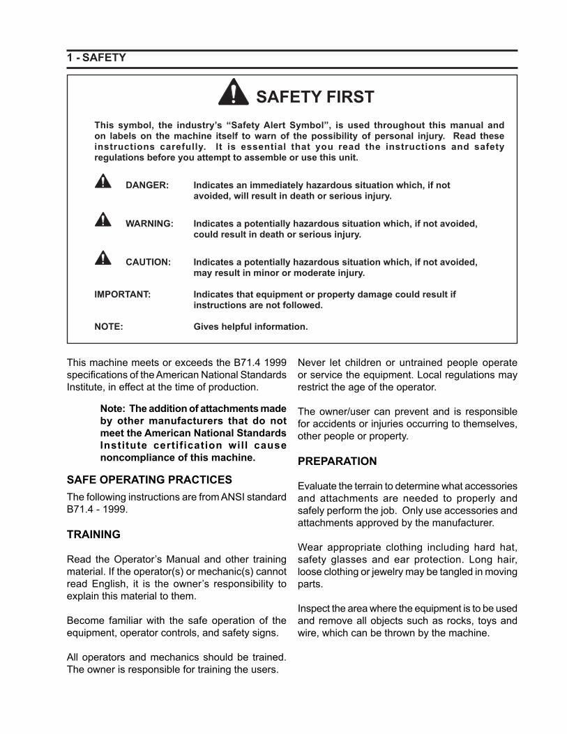
This symbol, the industry’s “Safety Alert Symbol”, is used throughout this manual andon labels on the machine itself to warn of the possibility of personal injury. Read theseinstructions carefully. It is essential that you read the instructions and safetyregulations before you attempt to assemble or use this unit.
DANGER: Indicates an immediately hazardous situation which, if not avoided, will result in death or serious injury.
WARNING: Indicates a potentially hazardous situation which, if not avoided, could result in death or serious injury.
CAUTION: Indicates a potentially hazardous situation which, if not avoided, may result in minor or moderate injury.
IMPORTANT: Indicates that equipment or property damage could result if instructions are not followed.
NOTE: Gives helpful information.
SAFETY FIRST
This machine meets or exceeds the B71.4 1999 specifi cations of the American National Standards Institute, in effect at the time of production.
Note: The addition of attachments made by other manufacturers that do not meet the American National Standards Institute certification will cause noncompliance of this machine.
SAFE OPERATING PRACTICESThe following instructions are from ANSI standard B71.4 - 1999.
TRAINING
Read the Operator’s Manual and other training material. If the operator(s) or mechanic(s) cannot read English, it is the owner’s responsibility to explain this material to them.
Become familiar with the safe operation of the equipment, operator controls, and safety signs.
All operators and mechanics should be trained. The owner is responsible for training the users.
Never let children or untrained people operate or service the equipment. Local regulations may restrict the age of the operator.
The owner/user can prevent and is responsible for accidents or injuries occurring to themselves, other people or property.
PREPARATION
Evaluate the terrain to determine what accessories and attachments are needed to properly and safely perform the job. Only use accessories and attachments approved by the manufacturer.
Wear appropriate clothing including hard hat, safety glasses and ear protection. Long hair, loose clothing or jewelry may be tangled in moving parts.
Inspect the area where the equipment is to be used and remove all objects such as rocks, toys and wire, which can be thrown by the machine.
- 2 SAFETY
Use extra care when handling gasoline and other fuels. They are fl ammable and vapors are explosive.
a. Use only an approved containerb. Never remove gas cap or add fuel with
engine running. Allow engine to cool before refueling. Do not smoke.
c. Never refuel or drain the machine indoors.
Check that operator’s presence controls, safety switches and shields are attached and functioning properly. Do not operate unless they are functioning properly.
OPERATION
Never run an engine in an enclosed area.
Only operate in good light, keeping away from holes and hidden hazards.
Be sure all drives are in neutral and parking brake is engaged before starting the engine. Only start engine from the operator’s position. Use seat belts if provided and the ROPS is installed.
Slow down and use extra care on hillsides. Be sure to travel in the recommended direction on hillsides. Turf conditions can affect the machine’s stability. Use caution while operating near drop-offs.
Slow down and use caution when making turns and when changing directions on slopes.
Never raise deck with the blades running.
Never operate with the PTO shield, or other guards not securely in place. Be sure all interlocks are attached, adjusted properly, and functioning properly.
Never operate with the discharge shield raised, removed or altered, unless using a grass catcher.
Do not change the engine governor setting or over speed the engine.
Stop on level ground, lower implements, disengage drives, engage parking brake (if provided), shut off engine before leaving the operator’s position for any reason including emptying the catchers or unclogging the chute.
Stop equipment and inspect blades after striking objects or if an abnormal vibration occurs. Make necessary repairs before resuming operations.
Keep hands and feet away from the cutting units.
Look behind and down before backing up to be sure of a clear path.
Never carry passengers and keep pets and bystanders away.
Slow down and use caution when crossing roads and sidewalks.
Stop blades if not mowing.
Be aware of the mower discharge direction and do not point it at anyone.
Do not operate the mower under the infl uence of alcohol or drugs.
Use care when loading or unloading the machine into a trailer or truck.
Use care when approaching blind corners, shrubs, trees, or other objects that may obscure vision.
MAINTENANCE AND STORAGE
Disengage drives, lower implement, set parking brake, stop engine and remove key or disconnect spark plug wires. Wait for all movement to stop before adjusting, cleaning or repairing.
Clean grass and debris from cutting units, drives, muffl ers, and engine to help prevent fi res. Clean up oil or fuel spillage.
Let engine cool before storing and do not store near fl ame.
3 -
Shut off fuel while storing or transporting. Do not store fuel near fl ames or drain indoors.
Park the machine on level ground. Never allow untrained personnel to service machine.
Use jack stands to support components when required.
Carefully release pressure from components with stored energy.
Disconnect battery or remove spark plug wires before making any repairs. Disconnect the negative terminal first and the positive last. Reconnect positive fi rst and negative last.
Use care when checking blades. Wrap the blade (s) or wear gloves, and use caution when servicing them. Only replace blades. Never straighten or weld them.
Keep hands and feet away from moving parts. If possible, do not make adjustments with the engine running.
Charge batteries in an open well ventilated area, away from spark and fl ames. Unplug charger before connecting or disconnecting from battery. Wear protective clothing and use insulated tools.
Keep all parts in good working condition and all hardware tightened. Replace all worn or damaged decals.
The discharge shield is subject to wear and deterioration. Inspect it regularly. If replacement is required, always replace it with genuine Everride products.
EVERRIDE MOWER SAFETY
The following list of safety warnings are specifi c to EverRide products. This list will contain additional safety information that is important, but not covered by the ANSI standards.
This product is capable of amputating hands and feet and throwing objects. Always follow all safety instructions to avoid serious injury or death.
The safety of the operator is one of our number one concerns when designing a new piece of equipment. Our designers have built in as many safety features as possible. Even with these built in safety features, many accidents occur which could have been avoided by a few seconds of thought and a more careful approach to handling machinery. Accidents can be avoided by observing all safety precautions. Read and understand all precautions found in the operator’s manual before operating the EverRide mower. This equipment must only be operated by those who have been trained in its safe use.
In order to provide a better view, certain photographs or illustrations in this manual may show an assembly with a safety shield removed. However, a machine should never be operated without the safety shields installed. Keep all shields in place. If shield removal becomes necessary for repairs, replace shield prior to machine operation.
WARNING: DO NOT remove or obscure DANGER, WARNING, CAUTION or Instruction Decals. Replace any decals that are not readable or are missing. Replacement decals are available from your dealer. The actual location of these Safety Decals is illustrated at the end of this section.
GENERAL SAFETY RULES
This book must be made available to the operator of the EverRide mower at all times.
Read this book carefully and learn how to use the machine correctly. Become familiar with all ma-chine controls and how to stop the machine and the implements or attachments quickly.
SAFETY
- 4
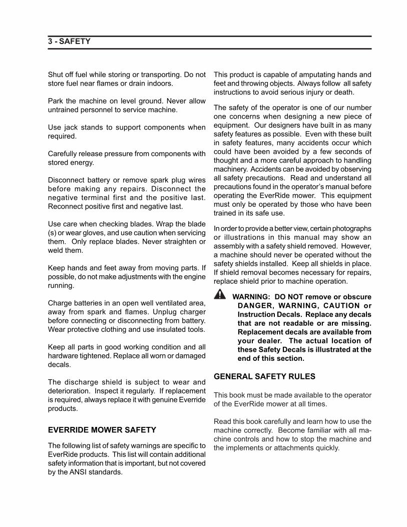
Beware of bystanders, particularly children!
Always look around to make sure that it is safe to start the engine or move the power unit. This is particularly important with higher noise levels as you may not hear people shouting.
KEEP PASSENGERS OFF
Only allow the operator on the machine. Do not carry passengers. This mower is designed for one (1) person, the driver.
Riders on the machine could be struck by foreign objects or thrown off the machine causing serious injury.
Riders obstruct the operator’s view which results in the machine being operated in a manner which is unsafe.
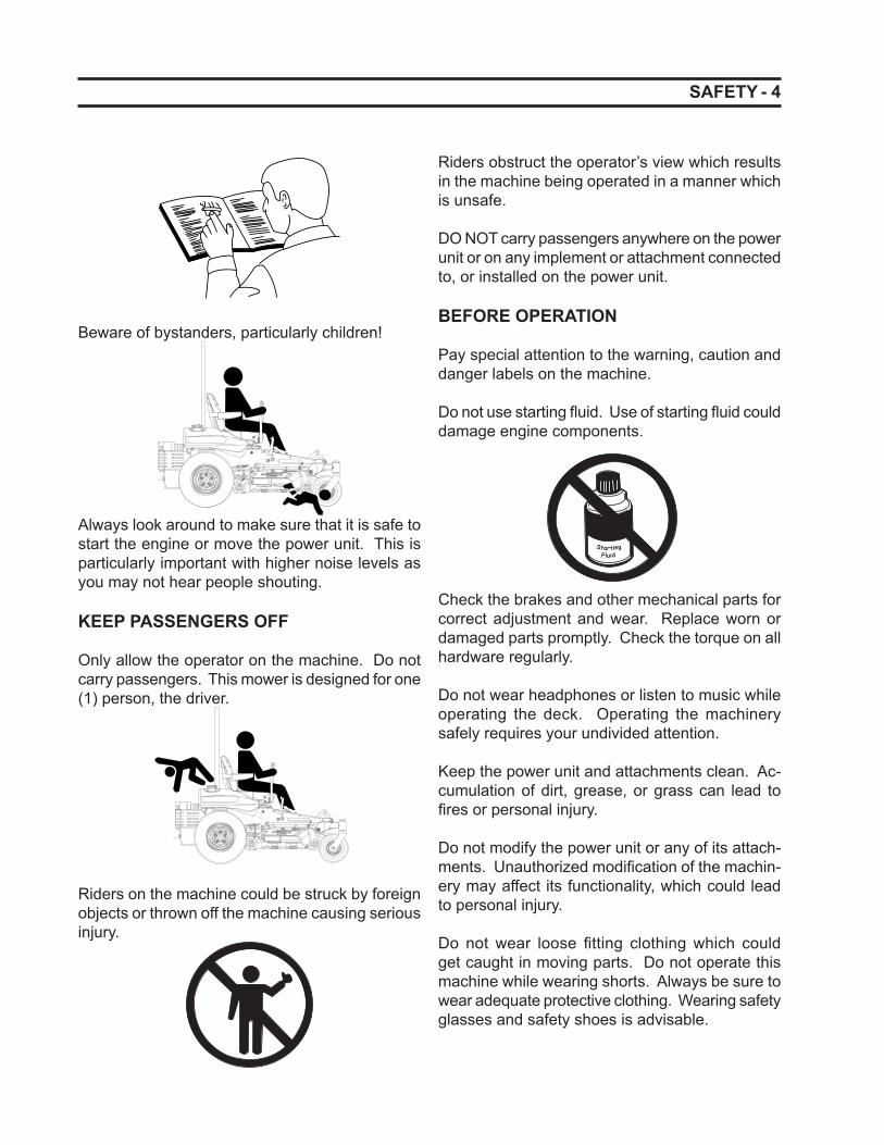
DO NOT carry passengers anywhere on the power unit or on any implement or attachment connected to, or installed on the power unit.
BEFORE OPERATION
Pay special attention to the warning, caution and danger labels on the machine.
Do not use starting fl uid. Use of starting fl uid could damage engine components.
StartingFluid
Check the brakes and other mechanical parts for correct adjustment and wear. Replace worn or damaged parts promptly. Check the torque on all hardware regularly.
Do not wear headphones or listen to music while operating the deck. Operating the machinery safely requires your undivided attention.
Keep the power unit and attachments clean. Ac-cumulation of dirt, grease, or grass can lead to fi res or personal injury.
Do not modify the power unit or any of its attach-ments. Unauthorized modifi cation of the machin-ery may affect its functionality, which could lead to personal injury.
Do not wear loose fi tting clothing which could get caught in moving parts. Do not operate this machine while wearing shorts. Always be sure to wear adequate protective clothing. Wearing safety glasses and safety shoes is advisable.
SAFETY
5 -
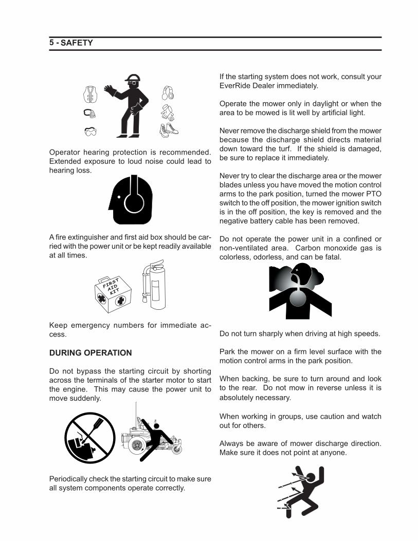
Operator hearing protection is recommended. Extended exposure to loud noise could lead to hearing loss.
A fi re extinguisher and fi rst aid box should be car-ried with the power unit or be kept readily available at all times.
FIRS
T
AID
KIT
Keep emergency numbers for immediate ac-cess.
DURING OPERATION
Do not bypass the starting circuit by shorting across the terminals of the starter motor to start the engine. This may cause the power unit to move suddenly.
Periodically check the starting circuit to make sure all system components operate correctly.
If the starting system does not work, consult your EverRide Dealer immediately.
Operate the mower only in daylight or when the area to be mowed is lit well by artifi cial light.
Never remove the discharge shield from the mower because the discharge shield directs material down toward the turf. If the shield is damaged, be sure to replace it immediately.
Never try to clear the discharge area or the mower blades unless you have moved the motion control arms to the park position, turned the mower PTO switch to the off position, the mower ignition switch is in the off position, the key is removed and the negative battery cable has been removed.
Do not operate the power unit in a confi ned or non-ventilated area. Carbon monoxide gas is colorless, odorless, and can be fatal.
Do not turn sharply when driving at high speeds.
Park the mower on a fi rm level surface with the motion control arms in the park position.
When backing, be sure to turn around and look to the rear. Do not mow in reverse unless it is absolutely necessary.
When working in groups, use caution and watch out for others.
Always be aware of mower discharge direction. Make sure it does not point at anyone.
SAFETY
- 6
Be sure the engine and rotating blades have stopped before putting hands or feet near the blade.
Disengage the blade drive when transporting the machine across drives, sidewalks, etc. Never raise the mower deck while the blades are turning.
Do not put hands or feet under or into the mower when it is running.
Do not touch the engine or muffl er when the en-gine is running or immediately after the engine has stopped. These areas may be hot enough to cause serious burns.
Do not drive the machine on streets or highways. Watch for traffi c when crossing streets or while mowing close to roads.
Always inspect the mower for damage after striking a foreign object. Always repair or replace dam-aged parts before restarting the mower deck.
Do not operate the power unit without the mower deck attached.
Make sure the machine and all attachments come to a complete stop before dismounting.
Before dismounting, disengage the PTO, lower all attachments, place the control levers in the park position, turn off the engine, and remove the key.
OPERATING ON SLOPES
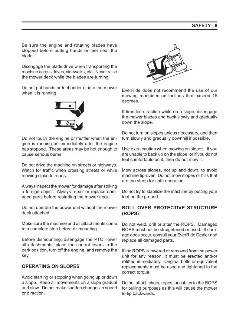
Avoid starting or stopping when going up or down a slope. Keep all movements on a slope gradual and slow. Do not make sudden changes in speed or direction.
EverRide does not recommend the use of our mowing machines on inclines that exceed 15 degrees.
If tires lose traction while on a slope, disengage the mower blades and back slowly and gradually down the slope.
Do not turn on slopes unless necessary, and then turn slowly and gradually downhill if possible.
Use extra caution when mowing on slopes. If you are unable to back up on the slope, or if you do not feel comfortable on it, then do not mow it.
Mow across slopes, not up and down, to avoid machine tip-over. Do not mow slopes or hills that are too steep for safe operation.
Do not try to stabilize the machine by putting your foot on the ground.
ROLL OVER PROTECTIVE STRUCTURE (ROPS)
Do not weld, drill or alter the ROPS. Damaged ROPS must not be straightened or used. If dam-age does occur, consult your EverRide Dealer and replace all damaged parts.
If the ROPS is lowered or removed from the power unit for any reason, it must be erected and/or refi tted immediately. Original bolts or equivalent replacements must be used and tightened to the correct torque.
Do not attach chain, ropes, or cables to the ROPS for pulling purposes as this will cause the mower to tip backwards.
SAFETY
7 -
EverRide does not recommend the use of the mower with the ROPS removed.
If you have a foldable ROPS, it can be folded down for mower storage. It must be pinned in the upright position prior to machine operation.
SEAT BELT USAGE
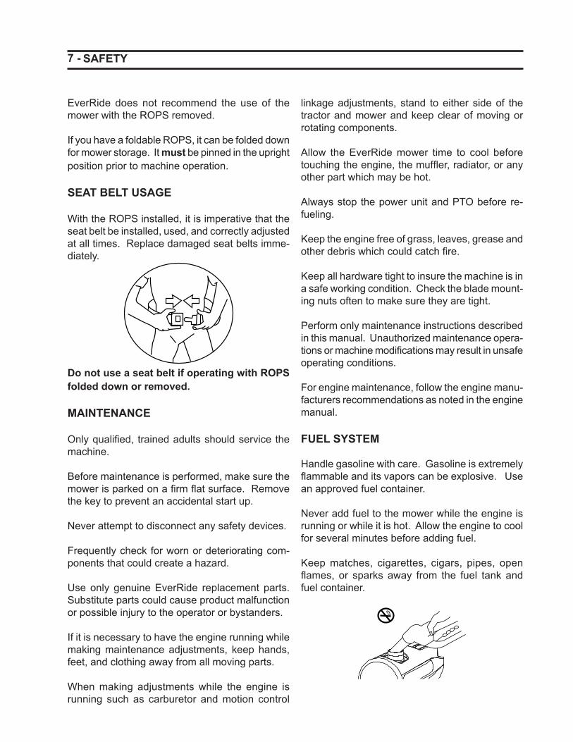
With the ROPS installed, it is imperative that the seat belt be installed, used, and correctly adjusted at all times. Replace damaged seat belts imme-diately.
Do not use a seat belt if operating with ROPS folded down or removed.
MAINTENANCE
Only qualifi ed, trained adults should service the machine.
Before maintenance is performed, make sure the mower is parked on a fi rm fl at surface. Remove the key to prevent an accidental start up.
Never attempt to disconnect any safety devices.
Frequently check for worn or deteriorating com-ponents that could create a hazard.
Use only genuine EverRide replacement parts. Substitute parts could cause product malfunction or possible injury to the operator or bystanders.
If it is necessary to have the engine running while making maintenance adjustments, keep hands, feet, and clothing away from all moving parts.
When making adjustments while the engine is running such as carburetor and motion control
linkage adjustments, stand to either side of the tractor and mower and keep clear of moving or rotating components.
Allow the EverRide mower time to cool before touching the engine, the muffl er, radiator, or any other part which may be hot.
Always stop the power unit and PTO before re-fueling.
Keep the engine free of grass, leaves, grease and other debris which could catch fi re.
Keep all hardware tight to insure the machine is in a safe working condition. Check the blade mount-ing nuts often to make sure they are tight.
Perform only maintenance instructions described in this manual. Unauthorized maintenance opera-tions or machine modifi cations may result in unsafe operating conditions.
For engine maintenance, follow the engine manu-facturers recommendations as noted in the engine manual.
FUEL SYSTEM
Handle gasoline with care. Gasoline is extremely fl ammable and its vapors can be explosive. Use an approved fuel container.
Never add fuel to the mower while the engine is running or while it is hot. Allow the engine to cool for several minutes before adding fuel.
Keep matches, cigarettes, cigars, pipes, open fl ames, or sparks away from the fuel tank and fuel container.
SAFETY
- 8
Always fi ll the fuel tanks outside using caution. Fill the tank until the fuel is about one inch from the top of the tank. Use a funnel or spout to prevent spilling. When refueling at a gas pump, always insure the nozzle contacts the neck of the tank while fi lling.
Replace the machine and container caps and clean up any spilled fuel before starting the engine.
Keep the mower and all fuel containers in a safe locked place to keep children from tampering with them.
Fuel system components rely upon clean fuel for lubrication and optimum performance. Extreme care must be taken to prevent ingress of dirt and moisture to prevent damage.
Use only nonmetal portable fuel containers ap-proved by the Underwriter’s Laboratory (U.L.) or the American Society for Testing and Materials (ASTM). If using a funnel, make sure it is plastic and has no screen or fi lter.
When practical, do not fuel the equipment on truck beds or on trailers. Remove them and fuel on the ground. If this is not possible, use a portable nonmetal fuel container to fi ll the equipment.
HYDRAULIC SYSTEM
Make sure all hydraulic fl uid, hoses, and lines are in good condition and all lines and fi ttings are tight before applying pressure to the hydraulic system.
Check hydraulic connections frequently. They can leak as a result of damage, as a result of vibration or because they have worked loose.
Relieve all pressures before disconnecting hoses or lines. Escaping oil under pressure can cause serious injury.
Escaping hydraulic fl uid under pressure can have suffi cient force to penetrate the skin, causing seri-ous injury. Before applying pressure to the system,
SAFETY
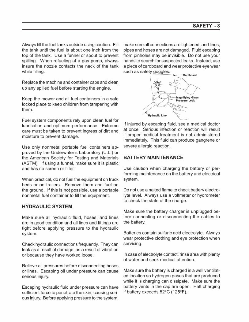
make sure all connections are tightened, and lines, pipes and hoses are not damaged. Fluid escaping from pinholes may be invisible. Do not use your hands to search for suspected leaks. Instead, use a piece of cardboard and wear protective eye wear such as safety goggles.
Hydraulic LineHydraulic Line
Pressure LeakPressure LeakMagnifying GlassMagnifying Glass
CardboardCardboard
If injured by escaping fl uid, see a medical doctor at once. Serious infection or reaction will result if proper medical treatment is not administered immediately. This fl uid can produce gangrene or severe allergic reaction.
BATTERY MAINTENANCE
Use caution when charging the battery or per-forming maintenance on the battery and electrical system.
Do not use a naked fl ame to check battery electro-lyte level. Always use a voltmeter or hydrometer to check the state of the charge.
Make sure the battery charger is unplugged be-fore connecting or disconnecting the cables to the battery.
Batteries contain sulfuric acid electrolyte. Always wear protective clothing and eye protection when servicing.
In case of electrolyte contact, rinse area with plenty of water and seek medical attention.
Make sure the battery is charged in a well ventilat-ed location so hydrogen gases that are produced while it is charging can dissipate. Make sure the battery vents in the cap are open. Halt charging if battery exceeds 52°C (125°F).
9 -
Keep sparks, fl ames, and smoking material away from the battery at all times. To avoid sparks, use care when removing battery cables from their posts.
Do not use or charge the refi llable type of battery if the fl uid level is below the lower limit level mark. Otherwise the parts may prematurely deteriorate which could shorten the battery’s service life or cause an explosion.
Before “jump starting” a battery, read and under-stand all instructions.
Disconnect the battery’s ground cable before work-ing on or near any electrical parts.
TIRE MAINTENANCE
Always insure the tires are infl ated to the correct pressure. Do not infl ate the tires above the recom-mended pressure in the operator’s manual.
Make sure all hardware, especially the wheel nuts and bolts have been tightened to the correct torque.
When removing a tire from the power unit, it is necessary to support it with blocks or stands, not a hydraulic jack.
Do not attempt to service a tire unless you have the proper equipment and experience to perform the job. If you are not qualifi ed to make the repairs, take the unit to your EverRide dealer or a qualifi ed repair service.
SAFETY
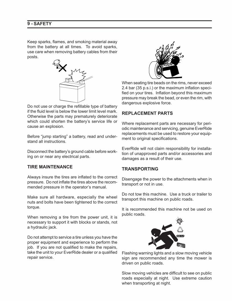
When seating tire beads on the rims, never exceed 2.4 bar (35 p.s.i.) or the maximum infl ation speci-fi ed on your tires. Infl ation beyond this maximum pressure may break the bead, or even the rim, with dangerous explosive force.
REPLACEMENT PARTS
Where replacement parts are necessary for peri-odic maintenance and servicing, genuine EverRide replacements must be used to restore your equip-ment to original specifi cations.
EverRide will not claim responsibility for installa-tion of unapproved parts and/or accessories and damages as a result of their use.
TRANSPORTING
Disengage the power to the attachments when in transport or not in use.
Do not tow this machine. Use a truck or trailer to transport this machine on public roads.
It is recommended this machine not be used on public roads.
Flashing warning lights and a slow moving vehicle sign are recommended any time the mower is driven on public roads.
Slow moving vehicles are diffi cult to see on public roads especially at night. Use extreme caution when transporting at night.
- 10 SLOPE GUIDE
(A) 15°
(B) 10°
(C) 5°
Line D
Line
E
Slope Lines
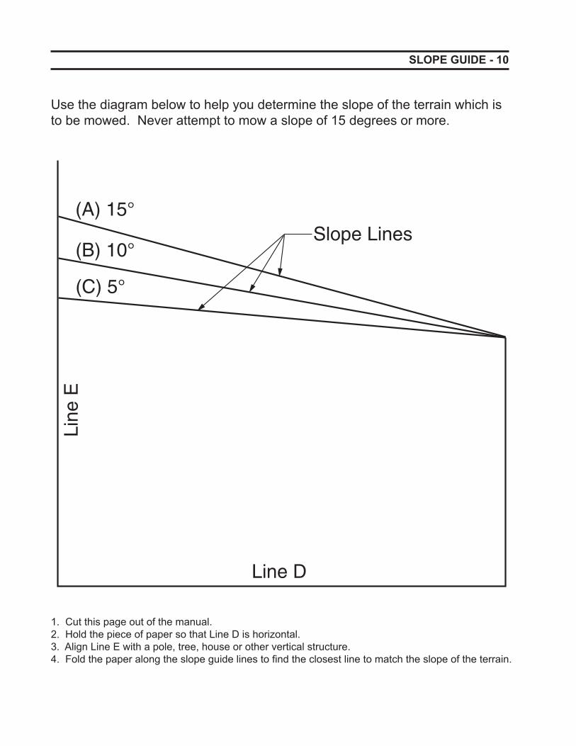
Use the diagram below to help you determine the slope of the terrain which is to be mowed. Never attempt to mow a slope of 15 degrees or more.
1. Cut this page out of the manual.2. Hold the piece of paper so that Line D is horizontal. 3. Align Line E with a pole, tree, house or other vertical structure.4. Fold the paper along the slope guide lines to fi nd the closest line to match the slope of the terrain.

11 - SLOPE GUIDE
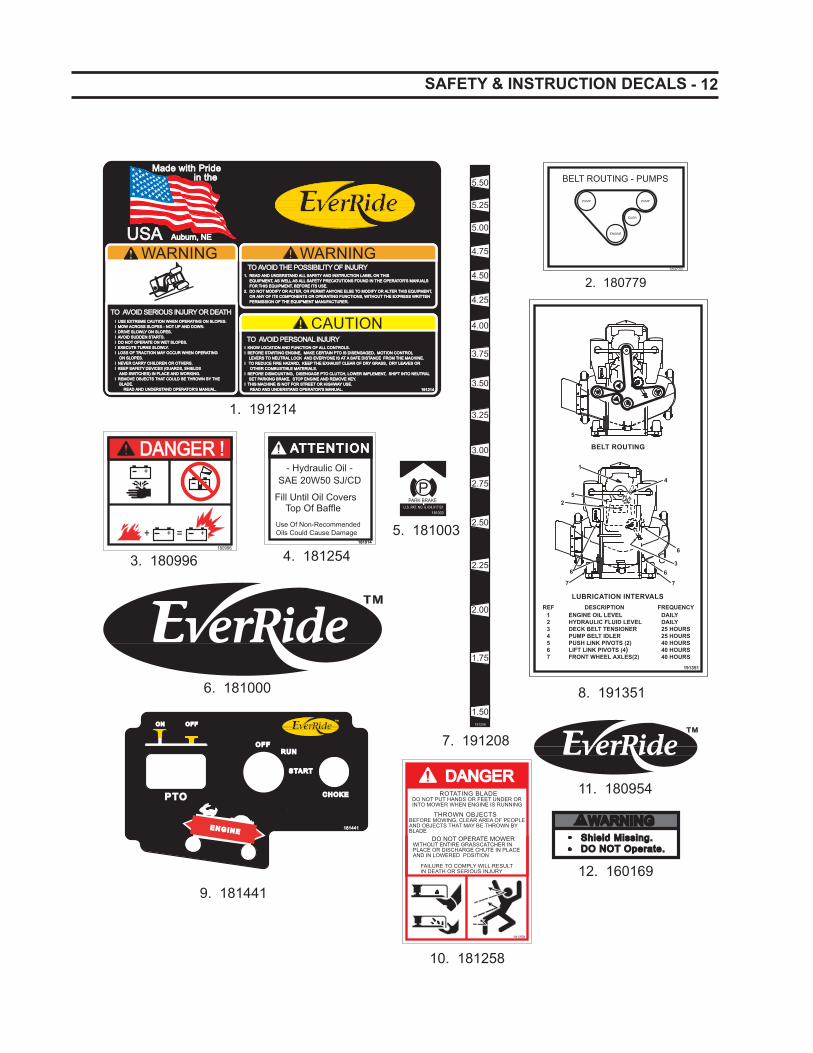
- 12 SAFETY & INSTRUCTION DECALS
PARK BRAKE
PU.S. PAT. NO. 6,434,917 B1
181003
180779
BELT ROUTING - PUMPS
ENGINE
PUMPPUMP
IDLER
1. 180953
5. 181003
2. 180779
1. 191214
8. 191351
7. 191208
6. 181000
DANGER !DANGER !+
+ = ++
+
180996
3. 180996
ATTENTIONATTENTION - Hydraulic Oil -SAE 20W50 SJ/CD
Use Of Non-RecommendedOils Could Cause Damage
Fill Until Oil Covers Top Of Baffle
181014181014
4. 181254
4.00
3.50
3.00
3.25
3.75
4.25
4.50
4.75
5.25
5.00
5.50
2.75
2.50
2.25
2.00
1.75
1.50191208
WARNING
TO AVOID SERIOUS INJURY OR DEATHTO AVOID SERIOUS INJURY OR DEATHl USE EXTREME CAUTION WHEN OPERATING ON SLOPES.l USE EXTREME CAUTION WHEN OPERATING ON SLOPES.l MOW ACROSS SLOPES - NOT UP AND DOWN.l MOW ACROSS SLOPES - NOT UP AND DOWN.l DRIVE SLOWLY ON SLOPES.l DRIVE SLOWLY ON SLOPES.l AVOID SUDDEN STARTS.l AVOID SUDDEN STARTS.l DO NOT OPERATE ON WET SLOPES.l DO NOT OPERATE ON WET SLOPES.l EXECUTE TURNS SLOWLY.l EXECUTE TURNS SLOWLY.l LOSS OF TRACTION MAY OCCUR WHEN OPERATING l LOSS OF TRACTION MAY OCCUR WHEN OPERATING ON SLOPES. ON SLOPES.l NEVER CARRY CHILDREN OR OTHERS.l NEVER CARRY CHILDREN OR OTHERS.l KEEP SAFETY DEVICES (GUARDS, SHIELDS l KEEP SAFETY DEVICES (GUARDS, SHIELDS AND SWITCHES) IN PLACE AND WORKING. AND SWITCHES) IN PLACE AND WORKING.l REMOVE OBJECTS THAT COULD BE THROWN BY THEl REMOVE OBJECTS THAT COULD BE THROWN BY THE BLADE. BLADE. READ AND UNDERSTAND OPERATOR'S MANUAL. READ AND UNDERSTAND OPERATOR'S MANUAL.
1. READ AND UNDERSTAND ALL SAFETY AND INSTRUCTION LABEL ON THIS 1. READ AND UNDERSTAND ALL SAFETY AND INSTRUCTION LABEL ON THIS EQUIPMENT, AS WELL AS ALL SAFETY PRECATUTIONS FOUND IN THE OPERATOR'S MANUALS EQUIPMENT, AS WELL AS ALL SAFETY PRECATUTIONS FOUND IN THE OPERATOR'S MANUALS FOR THIS EQUIPMENT, BEFORE ITS USE. FOR THIS EQUIPMENT, BEFORE ITS USE.2. DO NOT MODIFY OR ALTER, OR PERMIT ANYONE ELSE TO MODIFY OR ALTER THIS EQUIPMENT,2. DO NOT MODIFY OR ALTER, OR PERMIT ANYONE ELSE TO MODIFY OR ALTER THIS EQUIPMENT, OR ANY OF ITS COMPONENTS OR OPERATING FUNCTIONS, WITHOUT THE EXPRESS WRITTEN OR ANY OF ITS COMPONENTS OR OPERATING FUNCTIONS, WITHOUT THE EXPRESS WRITTEN PERMISSION OF THE EQUIPMENT MANUFACTURER. PERMISSION OF THE EQUIPMENT MANUFACTURER.
WARNINGTO AVOID THE POSSIBILITY OF INJURYTO AVOID THE POSSIBILITY OF INJURY
Made with Pride Made with Pride in the in the
Auburn, NE Auburn, NEUSAUSA
CAUTIONTO AVOID PERSONAL INJURY TO AVOID PERSONAL INJURY
l KNOW LOCATION AND FUNCTION OF ALL CONTROLS.l KNOW LOCATION AND FUNCTION OF ALL CONTROLS.l BEFORE STARTING ENGINE, MAKE CERTAIN PTO IS DISENGAGED, MOTION CONTROL l BEFORE STARTING ENGINE, MAKE CERTAIN PTO IS DISENGAGED, MOTION CONTROL LEVERS TO NEUTRAL LOCK AND EVERYONE IS AT A SAFE DISTANCE FROM THE MACHINE. LEVERS TO NEUTRAL LOCK AND EVERYONE IS AT A SAFE DISTANCE FROM THE MACHINE.l TO REDUCE FIRE HAZARD, KEEP THE EXHAUST CLEAR OF DRY GRASS, DRY LEAVES OR l TO REDUCE FIRE HAZARD, KEEP THE EXHAUST CLEAR OF DRY GRASS, DRY LEAVES OR OTHER COMBUSTIBLE MATERIALS. OTHER COMBUSTIBLE MATERIALS.l BEFORE DISMOUNTING, DISENGAGE PTO CLUTCH, LOWER IMPLEMENT, SHIFT INTO NEUTRAL l BEFORE DISMOUNTING, DISENGAGE PTO CLUTCH, LOWER IMPLEMENT, SHIFT INTO NEUTRAL SET PARKING BRAKE, STOP ENGINE AND REMOVE KEY. SET PARKING BRAKE, STOP ENGINE AND REMOVE KEY.l THIS MACHINE IS NOT FOR STREET OR HIGHWAY USE.l THIS MACHINE IS NOT FOR STREET OR HIGHWAY USE. READ AND UNDERSTAND OPERATOR'S MANUAL. READ AND UNDERSTAND OPERATOR'S MANUAL. 191214191214
9. 181441
11. 180954 ROTATING BLADEDO NOT PUT HANDS OR FEET UNDER ORINTO MOWER WHEN ENGINE IS RUNNING
DO NOT OPERATE MOWER WITHOUT ENTIRE GRASSCATCHER IN PLACE OR DISCHARGE CHUTE IN PLACE AND IN LOWERED POSITION
FAILURE TO COMPLY WILL RESULT IN DEATH OR SERIOUS INJURY
181258
DANGERDANGER
THROWN OBJECTS BEFORE MOWING, CLEAR AREA OF PEOPLE AND OBJECTS THAT MAY BE THROWN BY BLADE
10. 181258
WARNINGWARNINGShield Missing.Shield Missing.DO NOT Operate.DO NOT Operate.
12. 160169
LUBRICATION INTERVALSREF DESCRIPTION FREQUENCY
ENGINE OIL LEVELHYDRAULIC FLUID LEVELDECK BELT TENSIONERPUMP BELT IDLERPUSH LINK PIVOTS (2)LIFT LINK PIVOTS (4)FRONT WHEEL AXLES(2)
1234567
DAILYDAILY25 HOURS25 HOURS40 HOURS40 HOURS40 HOURS
191351
BELT ROUTING
1
2
366
6
5
4
77
P TOP TO
O NO N O F FO F F
O F FO F FR U NR U N
S TA RTS TA RT
C H O K EC H O K E
181441181441E N G I N EE N G I N E
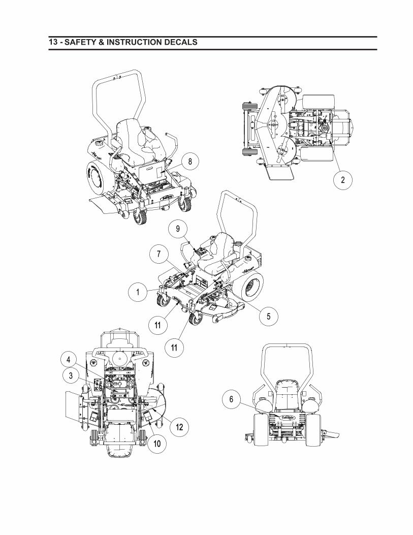
13 - SAFETY & INSTRUCTION DECALS
5
1
7
9
1111
1111
6
2
8
3
4
1010
1212
- 14 INTRODUCTION
INTRODUCTION
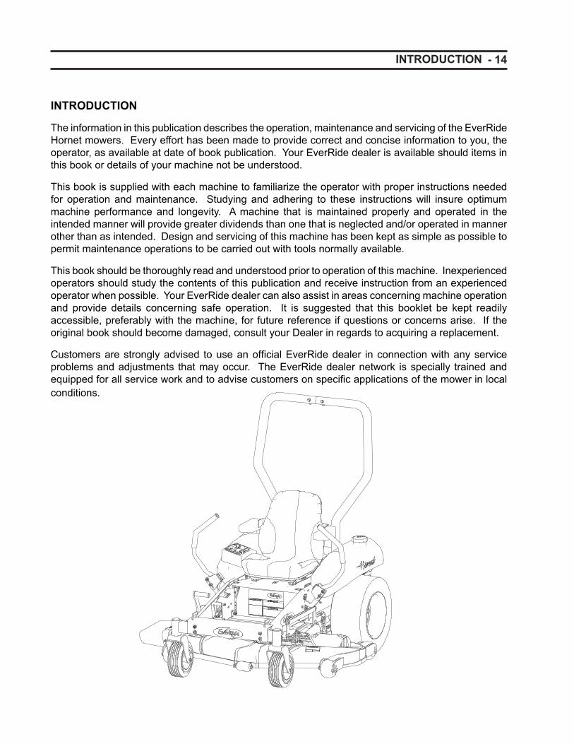
The information in this publication describes the operation, maintenance and servicing of the EverRide Hornet mowers. Every effort has been made to provide correct and concise information to you, the operator, as available at date of book publication. Your EverRide dealer is available should items in this book or details of your machine not be understood.
This book is supplied with each machine to familiarize the operator with proper instructions needed for operation and maintenance. Studying and adhering to these instructions will insure optimum machine performance and longevity. A machine that is maintained properly and operated in the intended manner will provide greater dividends than one that is neglected and/or operated in manner other than as intended. Design and servicing of this machine has been kept as simple as possible to permit maintenance operations to be carried out with tools normally available.
This book should be thoroughly read and understood prior to operation of this machine. Inexperienced operators should study the contents of this publication and receive instruction from an experienced operator when possible. Your EverRide dealer can also assist in areas concerning machine operation and provide details concerning safe operation. It is suggested that this booklet be kept readily accessible, preferably with the machine, for future reference if questions or concerns arise. If the original book should become damaged, consult your Dealer in regards to acquiring a replacement.
Customers are strongly advised to use an offi cial EverRide dealer in connection with any service problems and adjustments that may occur. The EverRide dealer network is specially trained and equipped for all service work and to advise customers on specifi c applications of the mower in local conditions.
15 - IDENTIFICATION
IDENTIFICATION
Model / Serial Numbers
Each EverRide Hornet mower is identifi ed by means of model and serial numbers. As a further identifi cation, the engine is also provided with identifi cation numbers.
To insure prompt, effi cient service when ordering parts or requesting repairs from an authorized EverRide dealer, these numbers must be provided.
MOWER MODEL
MOWER SERIAL NUMBER
This is what the mower serial number plate looks like.
Auburn Consolidated Industries, Inc.P.O. Box 350
Auburn, NE 68305-0350
Model Number
Serial Number
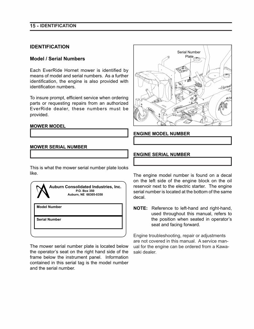
The mower serial number plate is located below the operator’s seat on the right hand side of the frame below the instrument panel. Information contained in this serial tag is the model number and the serial number.
Serial Number Plate
ENGINE MODEL NUMBER
ENGINE SERIAL NUMBER
The engine model number is found on a decal on the left side of the engine block on the oil reservoir next to the electric starter. The engine serial number is located at the bottom of the same decal.
NOTE: Reference to left-hand and right-hand, used throughout this manual, refers to the position when seated in operator’s seat and facing forward.
Engine troubleshooting, repair or adjustments are not covered in this manual. A service man-ual for the engine can be ordered from a Kawa-saki dealer.
- 16 INSTRUMENTS AND CONTROLS
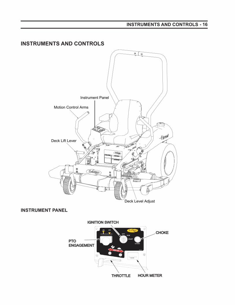
Deck Lift Lever
Motion Control Arms
Instrument Panel
Deck Level Adjust
INSTRUMENTS AND CONTROLS
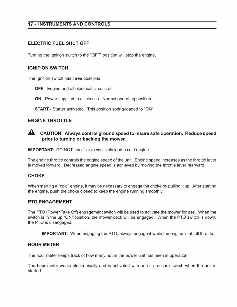
P T OP T O
THROTTLETHROTTLE
PTOPTOENGAGEMENTENGAGEMENT
CHOKECHOKE
IGNITION SWITCHIGNITION SWITCH
HOUR METERHOUR METER
INSTRUMENT PANEL
17 - INSTRUMENTS AND CONTROLS
ELECTRIC FUEL SHUT OFF
Turning the ignition switch to the “OFF” position will stop the engine.
IGNITION SWITCH
The Ignition switch has three positions.
OFF - Engine and all electrical circuits off.
ON - Power supplied to all circuits. Normal operating position.
START - Starter activated. This position spring-loaded to “ON”.
ENGINE THROTTLE
CAUTION: Always control ground speed to insure safe operation. Reduce speed prior to turning or backing the mower.
IMPORTANT: DO NOT “race” or excessively load a cold engine.
The engine throttle controls the engine speed of the unit. Engine speed increases as the throttle lever is moved forward. Decreased engine speed is achieved by moving the throttle lever rearward.
CHOKE
When starting a “cold” engine, it may be necessary to engage the choke by pulling it up. After starting the engine, push the choke closed to keep the engine running smoothly.
PTO ENGAGEMENT
The PTO (Power Take Off) engagement switch will be used to activate the mower for use. When the switch is in the up “ON” position, the mower deck will be engaged. When the PTO switch is down, the PTO is disengaged.
IMPORTANT: When engaging the PTO, always engage it while the engine is at full throttle.
HOUR METER
The hour meter keeps track of how many hours the power unit has been in operation.
The hour meter works electronically and is activated with an oil pressure switch when the unit is started.
- 18 OPERATING THE POWER UNIT
BREAK-IN PERIOD
� Operation of the mower within the fi rst fi fty hours can be a major factor in determining the performance and life of the engine and power unit.
� The engine may be operated at full RPM, but excessive load should be avoided. If engine begins to “bog down”, operate the power unit and mower at a slower ground speed while maintaining the engine speed.
� Check engine, pumps, and motors frequently during break-in period. Watch for evidence of leakage of fl uids. Replenish levels as required and repair any leaks that may have formed.
� Tighten any nuts, bolts or screws that may have loosened and tighten them as necessary. This is especially true of the wheel retaining nuts.
� Be observant to control arm and parking brake adjustment. Lining materials used on the park-ing brake will “bed in” in the fi rst few hours of operation and may necessitate the need for early and frequent readjustment.
� Keep area around the fuel tank fi ller cleaned and make sure the gasoline is of correct octane and free of contamination.
� Initial oil and oil fi lter change is after the fi rst 8 hours of use and every 100 hours after.
CAUTION: Proper maintenance practices cannot be overemphasized. They are required for safe operation. Consult the “Lubrication and Maintenance” section of this manual for full details.
MOUNTING AND DISMOUNTING SAFELY
DO NOT step on either side of the mower deck when mounting or dismounting the power unit. Step over the deck when mounting or dismount-ing.
FUEL
Make sure the fuel tank is full, but do not overfi ll. Gas should remain one inch below the neck of the tank. Be sure to use unleaded gasoline with an octane rating of 87 or higher. The octane rat-ing of a gasoline is a measure of its resistance to knocking. You may use gasoline with up to 10% ethanol by volume.
NOTE: If knocking or pinging occurs, switch to a different brand or a higher oc-tane gasoline.
Make sure dirt and foreign matter is kept out of the fuel tank. Use only a clean funnel and fuel can to fi ll the tanks.
STARTING THE EVERRIDE MOWER
Pre Start Inspection
Prior to daily start-up of the mower, a few basic procedures should be followed to insure the ma-chine is in optimal operating condition.
� Make sure all safety shields are in place and secured properly.
� Make sure the operator is instructed on correct and safe operation of the power unit and related attachments and implements.
� Check engine and hydraulic reservoir oil and replenish as necessary.
� Check the pump belt and drive belt tension and adjust as necessary.
� Insure air intake screens are clear of debris to provide maximum engine cooling.
� General inspection of tires, tire pressure and wheel bolt torque. Observe for external signs of leakage and correct before operating the mower. Check motion control arms for loose-ness and correct position.
19 - OPERATING THE POWER UNIT
� Check for adequate fuel supply. It is recom-mended that the fuel tank be replenished fol-lowing each days use to reduce condensation and provide a full tank for next use.
WARNING: Carefully read and un-derstand the SAFETY section of this manual.
WARNING: Always start and operate the engine in a well ventilated area. If in an enclosed area, vent the exhaust outside.
WARNING: Do not modify or tamper with the exhaust system.
Normal Starting
CAUTION: Do not attempt to start the engine unless you are seated in the operator’s seat. Do not allow anyone on the mower except the operator.
Sit on the operator’s seat. Be sure the handles are both facing out in the park position and the PTO is not engaged.
The choke control knob is located on the control panel. To start a cold engine, pull the choke con-trol up to the on position. After the engine starts, move the choke control down toward the “OFF” position, keeping enough choke to keep the engine running smoothly.
NOTE: Be sure the choke is in the “off” position during normal engine operation. Running with the choke in the “On” position can cause damage to the engine.
Use the throttle control lever to increase and de-crease the engine speed. Moving the lever forward will increase the engine speed while moving the throttle backwards will lower the engine speed. When starting the power unit, set the throttle at half speed.
Insert the key into the ignition switch and turn to the right to the start position and then release the key after the engine has started.
NOTE: Because of safety features, the engine can’t be started unless the control arms are in the park position, the operator is in the seat, and the mower PTO is off.
Allow the engine to idle for a few minutes before increasing the throttle or engaging the PTO.
Before turning off engine disengage the PTO, put the handles in neutral, and pull the throttle back to a low idle. Allow the engine to idle for a few minutes and then turn the engine off by turning the key left to the off position. Be sure to remove the key before getting out of the operator’s seat.
IMPORTANT: DO NOT leave the key in the ignition while the machine is unat-tended.
Do not operate the engine starter for more than thirty seconds at a time. An interval of at least two minutes should be allowed between cranking periods to prevent the starter from overheating or burning out.
Starting In Cold Weather
When the temperature is below -5°C (23°F) and the engine is cold do not try to start the engine for more than ten seconds at a time. If the engine does not start after 10 seconds, turn the ignition to “OFF” and let the mower stand for 30 seconds. To protect the battery and the starter, make sure the starter does not turn for more than 10 seconds continuously.
Jump Starting The Power Unit
WARNING: Battery gases can be ex-plosive. Keep all cigarettes, sparks or fl ames away from the battery.
WARNING: If the battery is frozen, do not attempt to jump start the engine.
- 20 OPERATING THE POWER UNIT
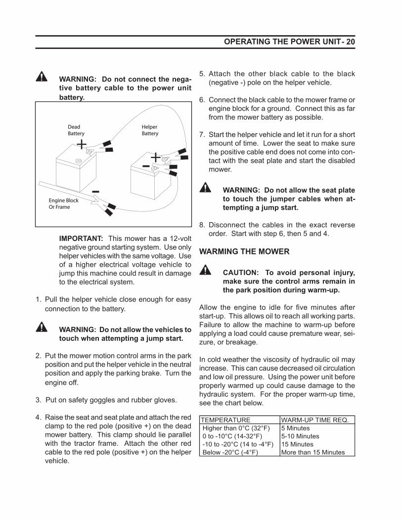
WARNING: Do not connect the nega-tive battery cable to the power unit battery.
+-+
-
DeadBattery
HelperBattery
Engine BlockOr Frame
IMPORTANT: This mower has a 12-volt negative ground starting system. Use only helper vehicles with the same voltage. Use of a higher electrical voltage vehicle to jump this machine could result in damage to the electrical system.
1. Pull the helper vehicle close enough for easy connection to the battery.
WARNING: Do not allow the vehicles to touch when attempting a jump start.
2. Put the mower motion control arms in the park position and put the helper vehicle in the neutral position and apply the parking brake. Turn the engine off.
3. Put on safety goggles and rubber gloves.
4. Raise the seat and seat plate and attach the red clamp to the red pole (positive +) on the dead mower battery. This clamp should lie parallel with the tractor frame. Attach the other red cable to the red pole (positive +) on the helper vehicle.
5. Attach the other black cable to the black (negative -) pole on the helper vehicle.
6. Connect the black cable to the mower frame or engine block for a ground. Connect this as far from the mower battery as possible.
7. Start the helper vehicle and let it run for a short amount of time. Lower the seat to make sure the positive cable end does not come into con-tact with the seat plate and start the disabled mower.
WARNING: Do not allow the seat plate to touch the jumper cables when at-tempting a jump start.
8. Disconnect the cables in the exact reverse order. Start with step 6, then 5 and 4.
WARMING THE MOWER
CAUTION: To avoid personal injury, make sure the control arms remain in the park position during warm-up.
Allow the engine to idle for fi ve minutes after start-up. This allows oil to reach all working parts. Failure to allow the machine to warm-up before applying a load could cause premature wear, sei-zure, or breakage. In cold weather the viscosity of hydraulic oil may increase. This can cause decreased oil circulation and low oil pressure. Using the power unit before properly warmed up could cause damage to the hydraulic system. For the proper warm-up time, see the chart below.
TEMPERATURE WARM-UP TIME REQ. Higher than 0°C (32°F) 5 Minutes 0 to -10°C (14-32°F) 5-10 Minutes -10 to -20°C (14 to -4°F) 15 Minutes Below -20°C (-4°F) More than 15 Minutes
21 - OPERATING THE POWER UNIT
INCREASING ACCELERATION
Moving the throttle lever forward increases the en-gine speed and moving it backwards will decrease the engine speed.
For good mowing performance it is important to run the engine at a high speed, but drive at a steady ground speed. If streaking or trailing occurs, de-crease your ground speed.
OPERATING THE EVERRIDE MOWER
Before using the mower to mow for the fi rst time, it is benefi cial to operate the EverRide mower at low speeds in an open area to acclimate yourself to the machine controls.
The control arms are located on both sides of the operator’s seat. These arms are used to control the forward, reverse and turning motion of the power unit. See the following section for an ex-planation of the steering controls.
STEERING CONTROLS
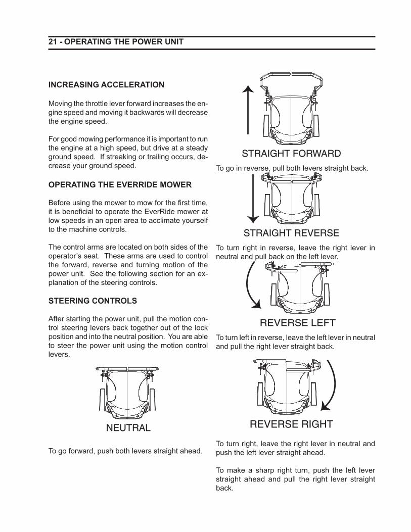
After starting the power unit, pull the motion con-trol steering levers back together out of the lock position and into the neutral position. You are able to steer the power unit using the motion control levers.
NEUTRAL
To go forward, push both levers straight ahead.
STRAIGHT FORWARD
To go in reverse, pull both levers straight back.
STRAIGHT REVERSE
To turn right in reverse, leave the right lever in neutral and pull back on the left lever.
REVERSE LEFT
To turn left in reverse, leave the left lever in neutral and pull the right lever straight back.
REVERSE RIGHT
To turn right, leave the right lever in neutral and push the left lever straight ahead.
To make a sharp right turn, push the left lever straight ahead and pull the right lever straight back.
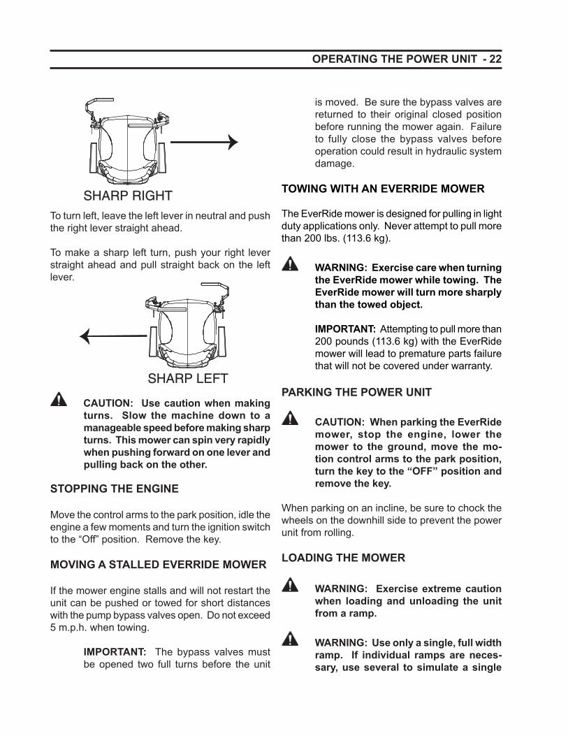
- 22
SHARP RIGHTTo turn left, leave the left lever in neutral and push the right lever straight ahead.
To make a sharp left turn, push your right lever straight ahead and pull straight back on the left lever.
SHARP LEFT
CAUTION: Use caution when making turns. Slow the machine down to a manageable speed before making sharp turns. This mower can spin very rapidly when pushing forward on one lever and pulling back on the other.
STOPPING THE ENGINE
Move the control arms to the park position, idle the engine a few moments and turn the ignition switch to the “Off” position. Remove the key.
MOVING A STALLED EVERRIDE MOWER
If the mower engine stalls and will not restart the unit can be pushed or towed for short distances with the pump bypass valves open. Do not exceed 5 m.p.h. when towing.
IMPORTANT: The bypass valves must be opened two full turns before the unit
OPERATING THE POWER UNIT
is moved. Be sure the bypass valves are returned to their original closed position before running the mower again. Failure to fully close the bypass valves before operation could result in hydraulic system damage.
TOWING WITH AN EVERRIDE MOWER
The EverRide mower is designed for pulling in light duty applications only. Never attempt to pull more than 200 lbs. (113.6 kg).
WARNING: Exercise care when turning the EverRide mower while towing. The EverRide mower will turn more sharply than the towed object.
IMPORTANT: Attempting to pull more than 200 pounds (113.6 kg) with the EverRide mower will lead to premature parts failure that will not be covered under warranty.
PARKING THE POWER UNIT
CAUTION: When parking the EverRide mower, stop the engine, lower the mower to the ground, move the mo-tion control arms to the park position, turn the key to the “OFF” position and remove the key.
When parking on an incline, be sure to chock the wheels on the downhill side to prevent the power unit from rolling.
LOADING THE MOWER
WARNING: Exercise extreme caution when loading and unloading the unit from a ramp.
WARNING: Use only a single, full width ramp. If individual ramps are neces-sary, use several to simulate a single
23 -
full width ramp. Use enough ramps to create an unbroken ramp surface wider than the unit.
WARNING: The deck HOC must be at the highest cutting height to prevent contacting the deck with the trailer or truck.
WARNING: Never exceed a 15 degree angle between the ramps and the truck or trailer when loading the mower.
WARNING: Avoid sudden acceleration and deceleration of the unit when load-ing and unloading the unit to avoid the mower from tipping backward.
The ramp should be long enough that the angles between the truck or trailer do not exceed 15 degrees. A steeper angle may cause the mower deck components to get hung up when moving the mower from ramp to truck or trailer. If loading on or near a slope, position the truck or trailer on the down side of the slope and the ramps should extend up the slope. This will minimize the ramp angle. The trailer or truck should be parked as level as possible to facilitate smooth loading of the mower.
TRANSPORTING THE MOWER
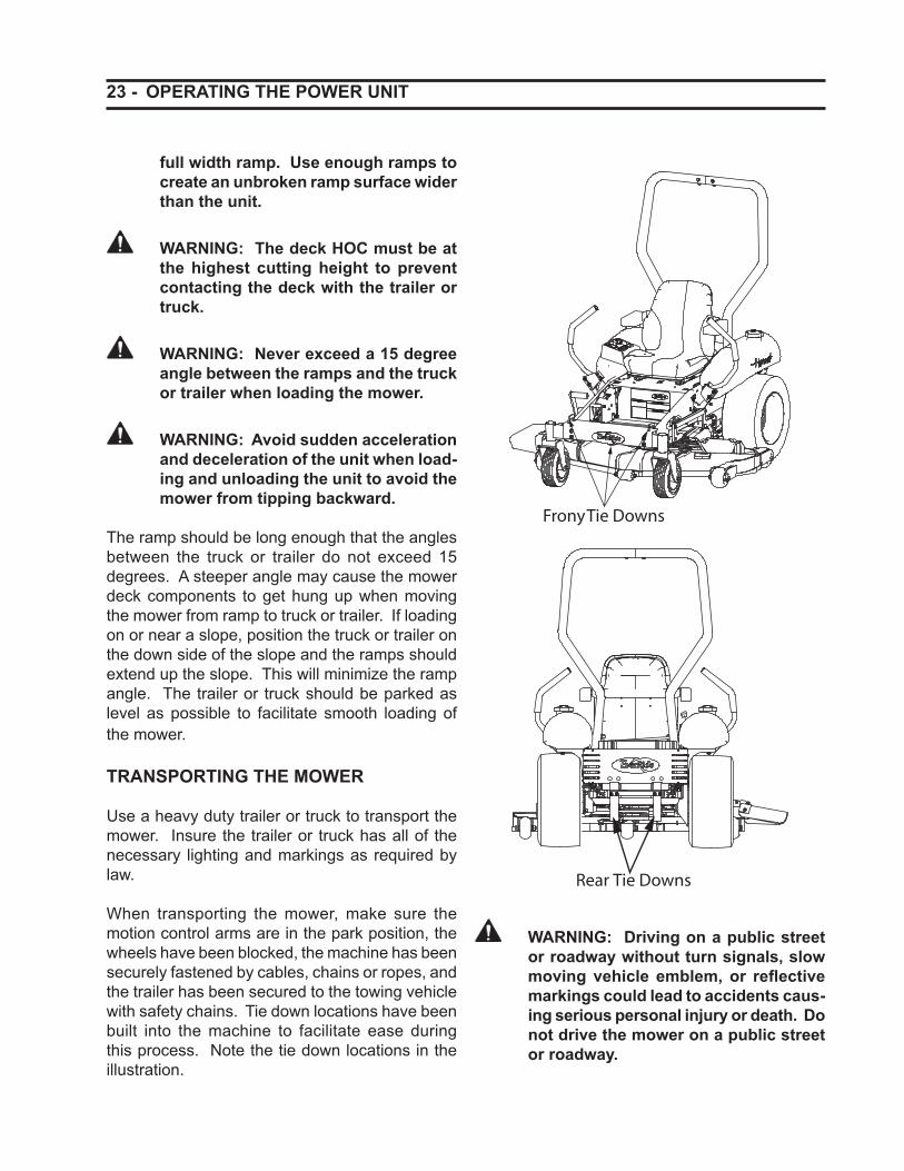
Use a heavy duty trailer or truck to transport the mower. Insure the trailer or truck has all of the necessary lighting and markings as required by law.
When transporting the mower, make sure the motion control arms are in the park position, the wheels have been blocked, the machine has been securely fastened by cables, chains or ropes, and the trailer has been secured to the towing vehicle with safety chains. Tie down locations have been built into the machine to facilitate ease during this process. Note the tie down locations in the illustration.
OPERATING THE POWER UNIT
WARNING: Driving on a public street or roadway without turn signals, slow moving vehicle emblem, or refl ective markings could lead to accidents caus-ing serious personal injury or death. Do not drive the mower on a public street or roadway.
- 24
GENERAL INFORMATION
The safe operation of the power unit and mower deck is the responsibility of the operator. The operator MUST be familiar with the mower and power unit controls, how they work, and all safety precautions BEFORE starting operation.
IMPORTANT: To avoid damage to the mower, re-torque all fastening hardware, including blade and spindle pulley retain-ing nuts, after the fi rst hour of mowing operation.
CAUTION: Inspect the mowing blade bolts daily, or whenever a blade has been removed. Torque is 110 to 130 Ft. Lbs. (150-177 N•m).
OPERATING SIDE DISCHARGE MOWERS
The mower has a hinged discharge shield that discharges the clippings out of the side of the deck and onto the ground.
DANGER: Without the discharge shield or a complete grass collector installed, you and others are exposed to rotat-ing mower blades and thrown debris. Contact with the mower blades or fl y-ing debris could cause severe injury or death.
DANGER: Never remove the discharge shield from the mower because the de-fl ector routes discharged material down toward the ground. If the discharge shield is ever damaged, do not use the mower until it has been replaced.
DANGER: Never put your hands or feet under the mower.
OPERATING THE MOWER
DANGER: Do not try to clear the mower discharge area or mower blades with-out fi rst turning the mower PTO to off, turning the ignition key to off, removing the key and disconnecting the battery cable.
TIPS FOR EFFICIENT MOWING
Blade sharpness affects the appearance of the mowed lawn. A dull or damaged blade will cause grass to appear torn or beaten off, rather than cut cleanly. Mowing blades should be checked regularly and kept sharp to insure the best lawn appearance.
Best results occur normally when the grass is maintained at a height of 2-3 inches (50mm-80mm) It is best to cut the grass often and not too short. To keep a healthy green lawn, do not cut more than 1/3 of the overall grass blade height.
Mower engine speed while mowing should be at the maximum rated RPM. This will insure proper blade speed for effective cutting and discharge of grass clippings.
Travel speed greatly affects mowing performance. The operator must use his or her own best judg-ment for the ground speed required for encoun-tered mowing conditions. Always use a lower ground speed for slower mowing, rather than lowering the engine RPM.
Mow often! Do not wait for the grass to get too tall. Short grass clippings will disperse better and deteriorate faster.
CAUTION: Clear the area of people, pets, and all visible debris before begin-ning mowing operations.
Mowing areas with tall grass or weeds may require cutting at 5.5 inches (maximum) height of cut. After mowing once, re-cut the entire area with the mower reset to the desired fi nal height of cut.
25 - OPERATING THE MOWER
When cutting along sidewalks, driveways, etc., it is advisable to mow with the discharge directed away from them for 2 or 3 passes. This will keep the grass clippings off of this area.
WARNING: Always keep the mower discharge directed away from people or animals which could be injured, or away from objects which could be dam-aged by debris thrown by the mowing blades.
The anti-scalp wheels on either side of the front of the mowing deck serve as a convenient mowing guide. When mowing, position the mower so the wheel overlaps the edge of the strip previously cut. This will assure full mowing coverage.
Always keep the left side of the mower toward trees, posts or any other obstacles on the fi rst trip around them.
CAUTION: Mow only during daylight hours, or when the area is well lit arti-fi cially.
When transporting, always disengage the mower PTO.
CUTTING HEIGHTS:
The mower can be adjusted to mow from 1.5 inch-es to 5.5 inches (38-76 mm) height of cut. Grass mowing height should be determined by encoun-tered conditions and personal preferences.
The following recommendations are provided as a guide for cutting height selection.
Lawns = 1.5” to 3” (38-76 mm)Field Cutting = 3” to 5.5” (76-140 mm)
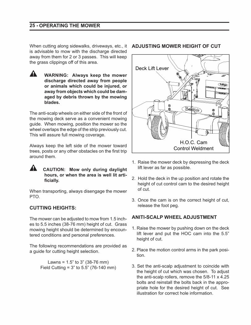
ADJUSTING MOWER HEIGHT OF CUT
Deck Lift Lever
H.O.C. CamControl Weldment
1. Raise the mower deck by depressing the deck lift lever as far as possible.
2. Hold the deck in the up position and rotate the height of cut control cam to the desired height of cut.
3. Once the cam is on the correct height of cut, release the foot peg.
ANITI-SCALP WHEEL ADJUSTMENT
1. Raise the mower by pushing down on the deck lift lever and put the HOC cam into the 5.5” height of cut.
2. Place the motion control arms in the park posi-tion.
3. Set the anti-scalp adjustment to coincide with the height of cut which was chosen. To adjust the anti-scalp rollers, remove the 5/8-11 x 4.25 bolts and reinstall the bolts back in the appro-priate hole for the desired height of cut. See illustration for correct hole information.
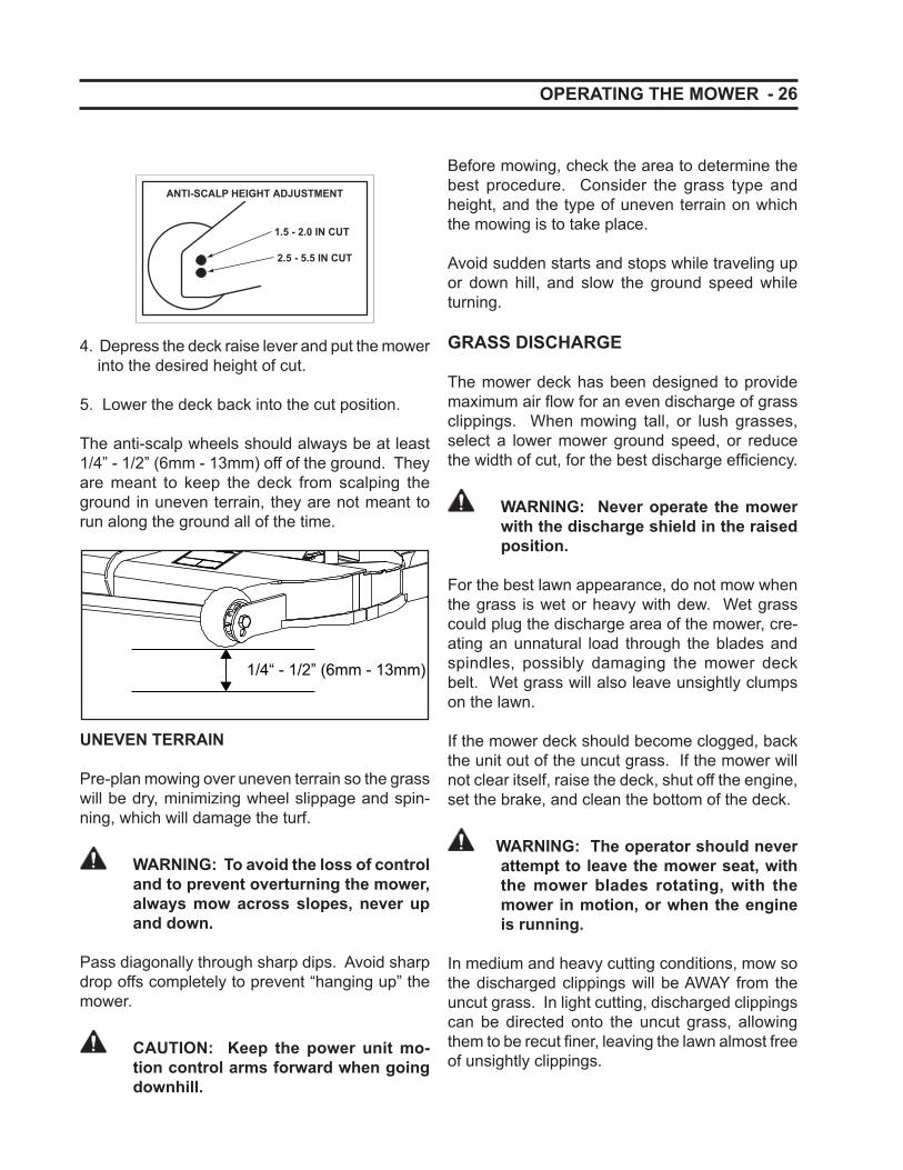
- 26
2.5 - 5.5 IN CUT
ANTI-SCALP HEIGHT ADJUSTMENT
1.5 - 2.0 IN CUT
4. Depress the deck raise lever and put the mower into the desired height of cut.
5. Lower the deck back into the cut position.
The anti-scalp wheels should always be at least 1/4” - 1/2” (6mm - 13mm) off of the ground. They are meant to keep the deck from scalping the ground in uneven terrain, they are not meant to run along the ground all of the time.
1/4“ - 1/2” (6mm - 13mm)
UNEVEN TERRAIN
Pre-plan mowing over uneven terrain so the grass will be dry, minimizing wheel slippage and spin-ning, which will damage the turf.
WARNING: To avoid the loss of control and to prevent overturning the mower, always mow across slopes, never up and down.
Pass diagonally through sharp dips. Avoid sharp drop offs completely to prevent “hanging up” the mower.
CAUTION: Keep the power unit mo-tion control arms forward when going downhill.
OPERATING THE MOWER
Before mowing, check the area to determine the best procedure. Consider the grass type and height, and the type of uneven terrain on which the mowing is to take place.
Avoid sudden starts and stops while traveling up or down hill, and slow the ground speed while turning.
GRASS DISCHARGE
The mower deck has been designed to provide maximum air fl ow for an even discharge of grass clippings. When mowing tall, or lush grasses, select a lower mower ground speed, or reduce the width of cut, for the best discharge effi ciency.
WARNING: Never operate the mower with the discharge shield in the raised position.
For the best lawn appearance, do not mow when the grass is wet or heavy with dew. Wet grass could plug the discharge area of the mower, cre-ating an unnatural load through the blades and spindles, possibly damaging the mower deck belt. Wet grass will also leave unsightly clumps on the lawn.
If the mower deck should become clogged, back the unit out of the uncut grass. If the mower will not clear itself, raise the deck, shut off the engine, set the brake, and clean the bottom of the deck.
WARNING: The operator should never attempt to leave the mower seat, with the mower blades rotating, with the mower in motion, or when the engine is running.
In medium and heavy cutting conditions, mow so the discharged clippings will be AWAY from the uncut grass. In light cutting, discharged clippings can be directed onto the uncut grass, allowing them to be recut fi ner, leaving the lawn almost free of unsightly clippings.

27 -
PARTS
Use only genuine EverRide service parts. Off the shelf (after market) repair parts may compromise the integrity of the unit. Parts that do not meet EverRide specifi cations may fail, causing injury, equipment or property damage.
Our part numbers can change. When ordering, use the part numbers listed below. If the numbers do change, your EverRide dealer will have the correct numbers.
When ordering, make sure to have your power unit and engine serial numbers readily available. You should have recorded these numbers on the identifi cation section of this manual.
PARTS
Common Mower Parts Common Tractor PartsItem Part No. Item Part No.Belt, Drive - 48" Deck 191378 Air Filter, Primary - Kawasaki 181071Belt, Drive - 52" Deck 191379 Air Filter, Secondary - Kawasaki 181072Blades, Mower - 48" Deck 191107 Air Filter, Briggs & Stratton 191630Blades, Mower - 52" Deck 191108 Pre-Cleaner, Briggs & Stratton 191632Discharge Shield 191559 Belt, Hydraulic Pump Drive 191199Shield, LH Deck Belt 191163 Cable, Choke 180273Shield, RH Deck Belt 191164 Cable, Throttle 181296Spindle Assembly - 48” 191517 Dampener, Steering Control 180231Spindle Assembly - 52” 191500 Engine Oil Filter - Kawasaki 181073Spring, Extension - Deck Tension 356473 Engine Oil Filter - Briggs & Stratton 191631Wheel, Gauge - 5.0” 191201 Fuel Filter 181060
Fuel Tank Cap 181251Hydraulic Oil Filter 180909Hydraulic Oil Reservoir Cap 191600Key, Ignition 105684Pump Cooler Fan 191621Solenoid, Starter 180640Switch, Ignition 180620Switch, Safety 191256Switch, PTO Engagement 136574Switch, Seat Safety 181074Wheel Fork Weldment 191575Wire Harness 191200
- 28 LUBRICATION AND MAINTENANCE
LUBRICATION AND PERIODIC MAINTENANCE
SPECIFICATIONS AND CAPACITIES
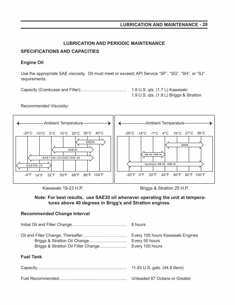
Engine Oil
Use the appropriate SAE viscosity. Oil must meet or exceed; API Service “SF”, “SG”, “SH”, or “SJ” requirements.
Capacity (Crankcase and Filter)…………………………… 1.8 U.S. qts. (1.7 L) Kawasaki 1.9 U.S. qts. (1.8 L) Briggs & Stratton Recommended Viscosity:
Ambient Temperature
-20°C -10°C 0°C 10°C 20°C 30°C 40°C
-4°F 14°F 32°F 50°F 68°F 86°F 104°F
SAE40
SAE30
SAE10W-30/SAE10W-40
SAE5W-20
Ambient Temperature
-29°C -18°C -7°C 4°C 16°C 27°C 38°C
-20°F 0°F 20°F 40°F 60°F 80°F 100°F
SAE30
5W-30-10W-30
Synthetic 5W-30, 10W-30
Kawasaki 19-23 H.P. Briggs & Stratton 25 H.P.
Note: For best results, use SAE30 oil whenever operating the unit at tempera-tures above 40 degrees in Brigg’s and Stratton engines.
Recommended Change Interval
Initial Oil and Filter Change………………………………… 8 hours
Oil and Filter Change, Thereafter.……………….………… Every 100 hours Kawasaki Engines Briggs & Stratton Oil Change................................ Every 50 hours Briggs & Stratton Oil Filter Change....................... Every 100 hours
Fuel Tank
Capacity………………………………………….………..…. 11.83 U.S. gals. (44.8 liters)
Fuel Recommended...............................…….………….... Unleaded 87 Octane or Greater
29 - LUBRICATION AND MAINTENANCE
Hydraulic System
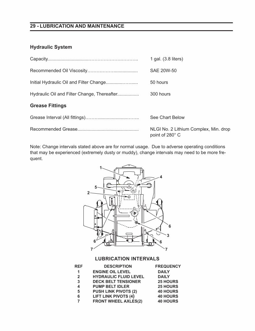
Capacity................................………………….……….. 1 gal. (3.8 liters)
Recommended Oil Viscosity……………….................. SAE 20W-50 Initial Hydraulic Oil and Filter Change.............……..... 50 hours
Hydraulic Oil and Filter Change, Thereafter................. 300 hours
Grease Fittings
Grease Interval (All fi ttings)………......................…….. See Chart Below
Recommended Grease................................................ NLGI No. 2 Lithium Complex, Min. drop point of 280° C
Note: Change intervals stated above are for normal usage. Due to adverse operating conditions that may be experienced (extremely dusty or muddy), change intervals may need to be more fre-quent.
LUBRICATION INTERVALSREF DESCRIPTION FREQUENCY
ENGINE OIL LEVELHYDRAULIC FLUID LEVELDECK BELT TENSIONERPUMP BELT IDLERPUSH LINK PIVOTS (2)LIFT LINK PIVOTS (4)FRONT WHEEL AXLES(2)
1234567
DAILYDAILY25 HOURS25 HOURS40 HOURS40 HOURS40 HOURS
1
2
366
6
5
4
77

- 30 LUBRICATION AND MAINTENANCE
Items marked (*) indicate initial service interval only. Subsequent (later) intervals marked “·”. Intervals above are for normal usage. Items marked [·] should be cleaned and inspected every 25 hours. Severe operating conditions (wet, dusty, etc.), or when previous servicing has indicated need for more frequent action, intervals may need to be more often.
PERIODIC MAINTENANCE SCHEDULE
Recommended Interval, Each:
Day 25 hr 50 hr 100 hr 250 hr Item To Check Action Required· All controls, switches Inspect and repair
· Hoses, fan belt, wiring Inspect and repair
· Grease fi ttings Lubricate
· Engine oil level Check and replenish
(*) · Engine oil and fi lter - Kawasaki Replace
(*) · Engine oil and fi lter - Briggs & Stratton
Replace
· Hydraulic oil level Check and replenish
(*) · Hydraulic oil & fi lter Replace
· Air screens Clean off debris
· Air cleaner dust ejector Clean
· Air cleaner - pre cleaner - Briggs & Stratton
Service air cleaner
[·] · Air cleaner elements - Kawasaki Inspect, clean or replace
[·] · Air cleaner cartridge - Briggs & Stratton
Inspect and clean
[·] · Air cleaner cartridge - Briggs & Stratton
Inspect and replace
· Fuel tank level Refi ll to full level
· · Fuel fi lter element Replace
· · Battery electrolyte level Check and replenish
· Brake adjustment & balance Check and adjust
· Tire pressure & condition Check and adjust
· Wheel bolt torque Check and tighten
· Steering free-play Check and repair
· Check safety shut off system Check and repair
· Clean grass buildup from deck Clean
· Inspect mower blades Check, sharpen or replace
· Check for loose hardware Replace or re-torque
· Inspect belts Tension or replace
31 -
AVOID FUMES
CAUTION: Engine exhaust fumes contain carbon monoxide and can cause serious illness or death.
CAUTION: Never run the mower’s engine inside an enclosed area. Operate it only outside or in a location with proper ven-tilation.
SERVICE ACCESS
CAUTION: Shut off the engine before servicing the mower.
CAUTION: Make sure the seat is fully raised and propped in place with a block of wood or similar material before performing any maintenance on the mower.
CAUTION: The seat can come down very quickly once the seat is released. Lower the seat slowly making sure to pay close attention that everything is clear.
To access the battery and the hydraulic reservoir it is necessary to raise the seat of the power unit. Use caution while lifting and insure the seat is propped in the upright position before beginning service on the mower.
To lower the seat back down, remove the prop and lower the seat slowly back into contact with the frame.
ENGINE OIL LEVEL
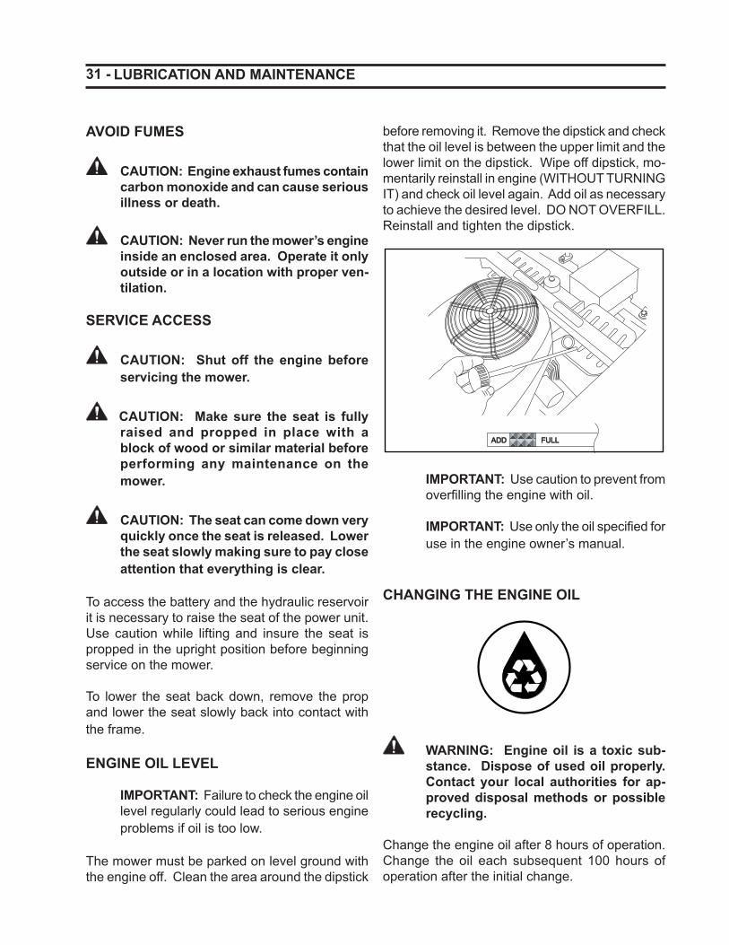
IMPORTANT: Failure to check the engine oil level regularly could lead to serious engine problems if oil is too low.
The mower must be parked on level ground with the engine off. Clean the area around the dipstick
LUBRICATION AND MAINTENANCE
before removing it. Remove the dipstick and check that the oil level is between the upper limit and the lower limit on the dipstick. Wipe off dipstick, mo-mentarily reinstall in engine (WITHOUT TURNING IT) and check oil level again. Add oil as necessary to achieve the desired level. DO NOT OVERFILL. Reinstall and tighten the dipstick.
ADDADD FULLFULL
IMPORTANT: Use caution to prevent from overfi lling the engine with oil.
IMPORTANT: Use only the oil specifi ed for use in the engine owner’s manual.
CHANGING THE ENGINE OIL
WARNING: Engine oil is a toxic sub-stance. Dispose of used oil properly. Contact your local authorities for ap-proved disposal methods or possible recycling.
Change the engine oil after 8 hours of operation. Change the oil each subsequent 100 hours of operation after the initial change.
- 32 LUBRICATION & MAINTENANCE
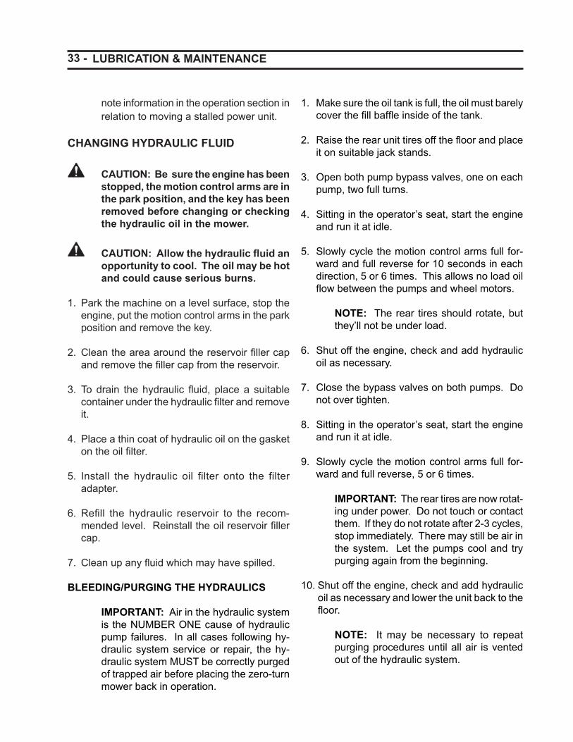
2. Clean the area around the oil fi lter to keep dirt and debris from the engine and rotate the oil fi lter counterclockwise to remove it. Wipe off the surface where the fi lter mounts.
3. Coat a fi lm of clean engine oil on the seal of the new fi lter.
Clean EngineOil
4. Install a new fi lter rotating it clockwise until the seal contacts the mounting surface. Rotate the fi lter 3/4 of a turn more by hand.
5. Refi ll with engine oil as specifi ed.
6. Run the engine for about 3 minutes, stop en-gine, and check for leakage around fi lter.
HYDROSTATIC MAINTENANCE
CAUTION: Avoid damage to the hy-draulic components as a result of con-tamination. Be sure to wipe around the fi ller neck and cap before removal of the hydraulic oil reservoir cap. Do not open the oil reservoir cap unless it is absolutely necessary.
Check the reservoir daily for the proper fluid level.
The pump and motor units require fl uid changes yearly or every 250 hours whichever occurs fi rst. The system fi lter should be changed initially after the fi rst 50 hours of break in. The fl uid and fi lter should be changed and the system cleaned if the fl uid would become contaminated with dirt, water, etc.
NOTE: The integrated pump/motor units are equipped with bypass valves. Please
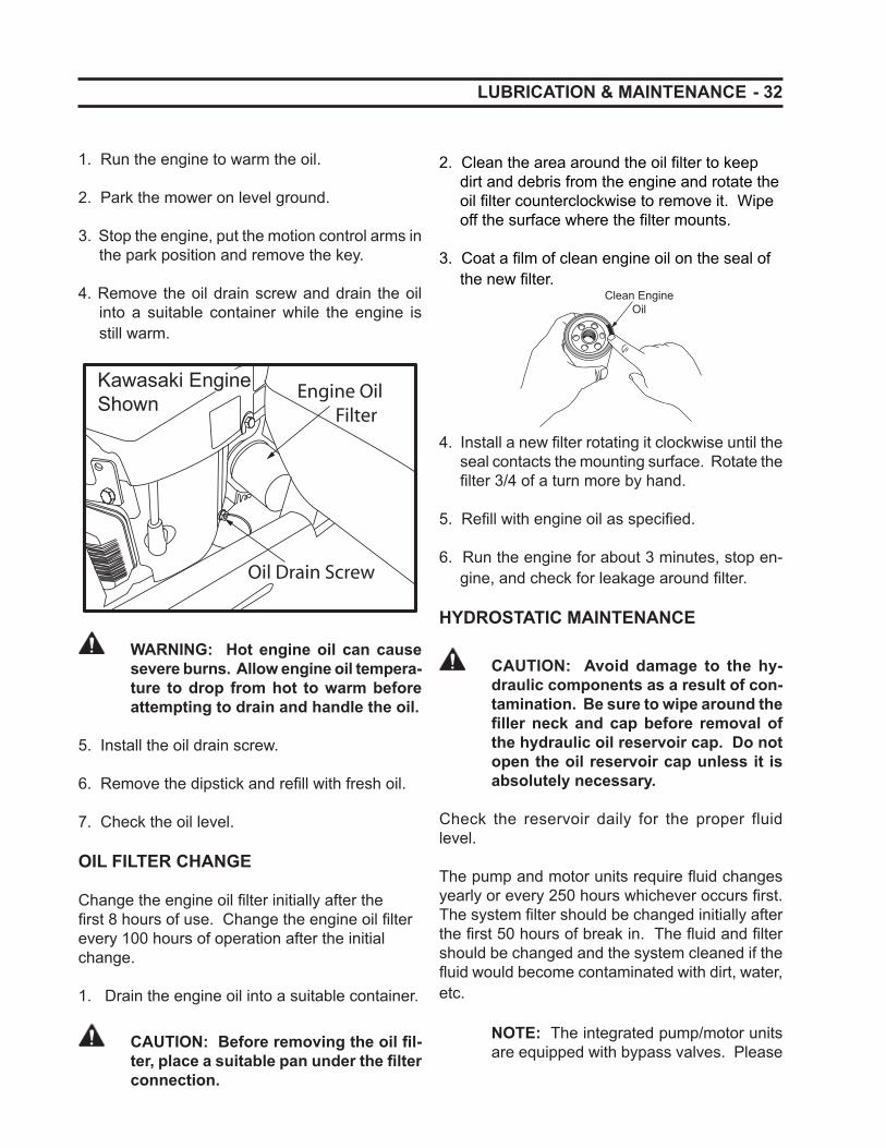
1. Run the engine to warm the oil.
2. Park the mower on level ground.
3. Stop the engine, put the motion control arms in the park position and remove the key.
4. Remove the oil drain screw and drain the oil into a suitable container while the engine is still warm.
Oil Drain Screw
Engine Oil Filter
Kawasaki EngineShown
WARNING: Hot engine oil can cause severe burns. Allow engine oil tempera-ture to drop from hot to warm before attempting to drain and handle the oil.
5. Install the oil drain screw.
6. Remove the dipstick and refi ll with fresh oil.
7. Check the oil level.
OIL FILTER CHANGE
Change the engine oil fi lter initially after the fi rst 8 hours of use. Change the engine oil fi lter every 100 hours of operation after the initial change.
1. Drain the engine oil into a suitable container.
CAUTION: Before removing the oil fi l-ter, place a suitable pan under the fi lter connection.
33 -
note information in the operation section in relation to moving a stalled power unit.
CHANGING HYDRAULIC FLUID
CAUTION: Be sure the engine has been stopped, the motion control arms are in the park position, and the key has been removed before changing or checking the hydraulic oil in the mower.
CAUTION: Allow the hydraulic fl uid an opportunity to cool. The oil may be hot and could cause serious burns.
1. Park the machine on a level surface, stop the engine, put the motion control arms in the park position and remove the key.
2. Clean the area around the reservoir fi ller cap and remove the fi ller cap from the reservoir.
3. To drain the hydraulic fl uid, place a suitable container under the hydraulic fi lter and remove it.
4. Place a thin coat of hydraulic oil on the gasket on the oil fi lter.
5. Install the hydraulic oil filter onto the filter adapter.
6. Refi ll the hydraulic reservoir to the recom-mended level. Reinstall the oil reservoir fi ller cap.
7. Clean up any fl uid which may have spilled.
BLEEDING/PURGING THE HYDRAULICS
IMPORTANT: Air in the hydraulic system is the NUMBER ONE cause of hydraulic pump failures. In all cases following hy-draulic system service or repair, the hy-draulic system MUST be correctly purged of trapped air before placing the zero-turn mower back in operation.
1. Make sure the oil tank is full, the oil must barely cover the fi ll baffl e inside of the tank.
2. Raise the rear unit tires off the fl oor and place it on suitable jack stands.
3. Open both pump bypass valves, one on each pump, two full turns.
4. Sitting in the operator’s seat, start the engine and run it at idle.
5. Slowly cycle the motion control arms full for-ward and full reverse for 10 seconds in each direction, 5 or 6 times. This allows no load oil fl ow between the pumps and wheel motors.
NOTE: The rear tires should rotate, but they’ll not be under load.
6. Shut off the engine, check and add hydraulic oil as necessary.
7. Close the bypass valves on both pumps. Do not over tighten.
8. Sitting in the operator’s seat, start the engine and run it at idle.
9. Slowly cycle the motion control arms full for-ward and full reverse, 5 or 6 times.
IMPORTANT: The rear tires are now rotat-ing under power. Do not touch or contact them. If they do not rotate after 2-3 cycles, stop immediately. There may still be air in the system. Let the pumps cool and try purging again from the beginning.
10. Shut off the engine, check and add hydraulic oil as necessary and lower the unit back to the fl oor.
NOTE: It may be necessary to repeat purging procedures until all air is vented out of the hydraulic system.
LUBRICATION & MAINTENANCE
- 34
CHECKING THE HYDRAULIC HOSES
Inspect the hydraulic hoses to insure they are in good working order every 200 hours.
Check both the hoses and hose clamps to insure there is no wear or damage. If either is found worn or damaged, repair or replace them at once.
BATTERY MAINTENANCE
WARNING: Battery posts, terminals and related accessories contain lead and lead components, chemicals known by the state of California to cause cancer and reproductive harm.
The original battery shipped with the mower is maintenance free and non-accessible.
If the battery is weak, the engine will be diffi cult to start. It is important to check the battery per-formance periodically.
INSTALLING THE BATTERY
1. Insert the battery (1) in the tray with the nega-tive post on the right side and positive post on the left side.
2. Install the positive battery cable to the positive post on the battery.
3. Install the negative battery cable to the nega-tive post on the battery.
4. Secure the cables by inserting a 5/16-18 x 5/8 carriage bolt through the battery post and through the battery cable. Secure it with a 5/16-18 whiz locknut.
5. Install the red terminal boot over both the posi-tive post and the positive cable.
6. Secure the battery in place by inserting one end of the hook band into the battery tray and running the other end over the top of the
battery into the slot on the opposite end of the battery tray.
REMOVING THE BATTERY
WARNING: The battery terminals or metal tools could short against the metal components of the mower causing a spark that could ignite explosive battery gases. When removing the battery from the mower, do not allow the battery ter-minals to touch any part of the machine. Do not allow metal tools to touch metal parts of the machine while in contact with the battery terminals.
WARNING: Incorrect battery cable rout-ing could damage the mower or cause a spark that could result in explosive battery gases being ignited.
WARNING: Always disconnect the black (negative) battery cable before discon-necting the red (positive) battery cable. Always reconnect the red (positive) bat-tery cable fi rst before reconnecting the black (negative) battery cable.
1. Disengage the PTO engagement switch, put the motion control arms in the park position, turn the ignition key to off and remove the key.
2. Raise the seat and prop it in the upright posi-tion.
3. Disconnect the negative battery cable from the battery terminal.
4. Slide the red boot off of the positive battery ter-minal and remove the positive battery cable.
5. Remove the rubber strap securing the battery in place.
6. Carefully remove the battery using caution to avoid touching the terminal posts on any metal parts.
LUBRICATION & MAINTENANCE

35 - LUBRICATION & MAINTENANCE
CHARGING THE BATTERY
WARNING: Charging the battery pro-duces explosive gases. Never smoke near the battery and keep sparks and fl ames away.
IMPORTANT: Always keep the battery fully charged. This is extremely important when the temperature is below freezing. (32 de-grees Fahrenheit or 0 degrees Celsius)
1. Remove the battery from the battery compart-ment under the seat. (see “Removing The Battery” on the prior page)
2. Check the electrolyte level.
NOTE: It is only necessary to check the elec-trolyte level on batteries that are not mainte-nance free.
3. Make sure the fi ller caps have been reinstalled on the battery and charge the battery 10-15 minutes on 25-30 amps or 30 minutes at 4-6 amps.
4. After the battery has been fully charged, dis-connect the charger from the power source and then disconnect the battery from the charger.
5. Install the battery in the machine and connect the battery cables.
CLEANING BATTERY AND TERMINALS
CAUTION: The battery produces a fl am-mable and explosive gas. The battery may explode. Do not smoke near the battery. Always wear eye protection and gloves. Do not allow direct metal con-tact across the battery posts. Always remove the negative battery cable fi rst when removing the battery.
1. Disconnect and remove the battery.
2. Wash the battery with a solution consisting of four tablespoons of baking soda to one gallon of water. Use caution to insure the solution does not get into the battery cells.
3. Rinse the battery with plain water and allow to dry.
4. Clean the terminals and wire ends with a wire brush until they are bright.
5. Reinstall the battery.
6. Reattach the battery cables.
7. Apply a petroleum jelly or a silicone spray to prevent corrosion.
REPLACING FUSES
IMPORTANT: Avoid damage to the elec-trical circuit. Use only the same size fuse as was originally installed.
There are two fuses on your EverRide mower. One is located on the plastic shroud on the left hand side of the engine and the other is located on the left hand side of the frame next to the relay block. Both are 20 amp fuses.
1. Remove the defective fuse from the socket.
2. Check the metal clip in the fuse window and discard the fuse if it is broken.
3. Install the new fuse in its socket.
SAFETY CHECKS
Check all safety switches daily. Use the following instructions to check the performance of the sys-tem. If any of these tests should fail, it is necessary to have the unit repaired immediately.
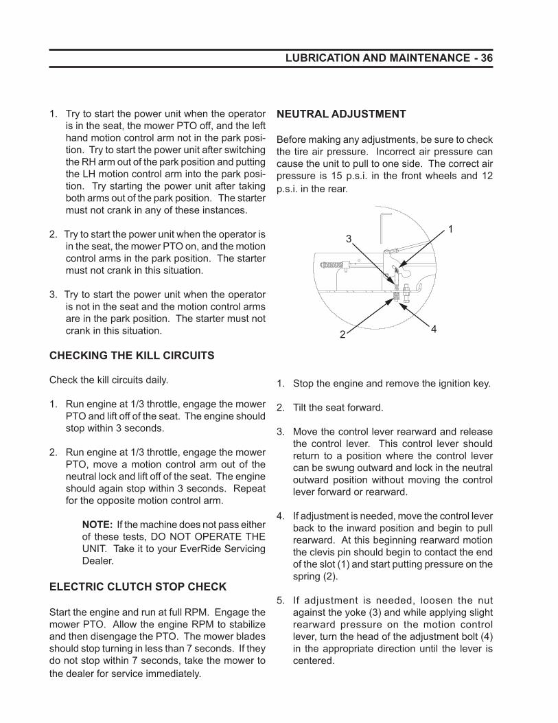
- 36 LUBRICATION AND MAINTENANCE
1. Try to start the power unit when the operator is in the seat, the mower PTO off, and the left hand motion control arm not in the park posi-tion. Try to start the power unit after switching the RH arm out of the park position and putting the LH motion control arm into the park posi-tion. Try starting the power unit after taking both arms out of the park position. The starter must not crank in any of these instances.
2. Try to start the power unit when the operator is in the seat, the mower PTO on, and the motion control arms in the park position. The starter must not crank in this situation.
3. Try to start the power unit when the operator is not in the seat and the motion control arms are in the park position. The starter must not crank in this situation.
CHECKING THE KILL CIRCUITS
Check the kill circuits daily.
1. Run engine at 1/3 throttle, engage the mower PTO and lift off of the seat. The engine should stop within 3 seconds.
2. Run engine at 1/3 throttle, engage the mower PTO, move a motion control arm out of the neutral lock and lift off of the seat. The engine should again stop within 3 seconds. Repeat for the opposite motion control arm.
NOTE: If the machine does not pass either of these tests, DO NOT OPERATE THE UNIT. Take it to your EverRide Servicing Dealer.
ELECTRIC CLUTCH STOP CHECK
Start the engine and run at full RPM. Engage the mower PTO. Allow the engine RPM to stabilize and then disengage the PTO. The mower blades should stop turning in less than 7 seconds. If they do not stop within 7 seconds, take the mower to the dealer for service immediately.
NEUTRAL ADJUSTMENT
Before making any adjustments, be sure to check the tire air pressure. Incorrect air pressure can cause the unit to pull to one side. The correct air pressure is 15 p.s.i. in the front wheels and 12 p.s.i. in the rear.
1
2
3
4
1. Stop the engine and remove the ignition key.
2. Tilt the seat forward.
3. Move the control lever rearward and release the control lever. This control lever should return to a position where the control lever can be swung outward and lock in the neutral outward position without moving the control lever forward or rearward.
4. If adjustment is needed, move the control lever back to the inward position and begin to pull rearward. At this beginning rearward motion the clevis pin should begin to contact the end of the slot (1) and start putting pressure on the spring (2).
5. If adjustment is needed, loosen the nut against the yoke (3) and while applying slight rearward pressure on the motion control lever, turn the head of the adjustment bolt (4) in the appropriate direction until the lever is centered.
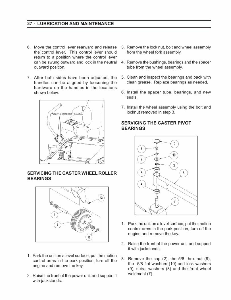
37 - LUBRICATION AND MAINTENANCE
3. Remove the lock nut, bolt and wheel assembly from the wheel fork assembly.
4. Remove the bushings, bearings and the spacer tube from the wheel assembly.
5. Clean and inspect the bearings and pack with clean grease. Replace bearings as needed.
6. Install the spacer tube, bearings, and new seals.
7. Install the wheel assembly using the bolt and locknut removed in step 3.
SERVICING THE CASTER PIVOT BEARINGS
28
1010
3
4 6
11
7
12
5
1
9
4
13
1. Park the unit on a level surface, put the motion control arms in the park position, turn off the engine and remove the key.
2. Raise the front of the power unit and support it with jackstands.
3. Remove the cap (2), the 5/8 hex nut (8), the 5/8 fl at washers (10) and lock washers (9), spiral washers (3) and the front wheel weldment (7).
6. Move the control lever rearward and release the control lever. This control lever should return to a position where the control lever can be swung outward and lock in the neutral outward position.
7. After both sides have been adjusted, the handles can be aligned by loosening the hardware on the handles in the locations shown below.
SERVICING THE CASTER WHEEL ROLLER BEARINGS
28
10
3
4 6
11
7
1212
5
1
9
4
1313
1. Park the unit on a level surface, put the motion control arms in the park position, turn off the engine and remove the key.
2. Raise the front of the power unit and support it with jackstands.
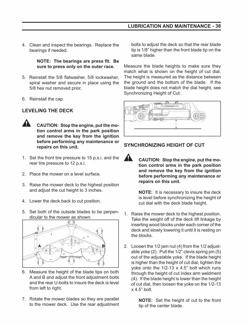
- 38 LUBRICATION AND MAINTENANCE
4. Clean and inspect the bearings. Replace the bearings if needed.
NOTE: The bearings are press fi t. Be sure to press only on the outer race.
5. Reinstall the 5/8 fl atwasher, 5/8 lockwasher, spiral washer and secure in place using the 5/8 hex nut removed prior.
6. Reinstall the cap.
LEVELING THE DECK
CAUTION: Stop the engine, put the mo-tion control arms in the park position and remove the key from the ignition before performing any maintenance or repairs on this unit.
1. Set the front tire pressure to 15 p.s.i. and the rear tire pressure to 12 p.s.i.
2. Place the mower on a level surface.
3. Raise the mower deck to the highest position and adjust the cut height to 3 inches.
4. Lower the deck back to cut position.
5. Set both of the outside blades to be perpen-dicular to the mower as shown.
A B
6. Measure the height of the blade tips on both
A and B and adjust the front adjustment bolts and the rear U-bolts to insure the deck is level from left to right.
7. Rotate the mower blades so they are parallel to the mower deck. Use the rear adjustment
bolts to adjust the deck so that the rear blade tip is 1/8” higher than the front blade tip on the same blade.
Measure the blade heights to make sure they match what is shown on the height of cut dial. The height is measured as the distance between the ground and the bottom of the blade. If the blade height does not match the dial height, see Synchronizing Height of Cut.
SYNCHRONIZING HEIGHT OF CUT
CAUTION: Stop the engine, put the mo-tion control arms in the park position and remove the key from the ignition before performing any maintenance or repairs on this unit.
NOTE: It is necessary to insure the deck is level before synchronizing the height of cut dial with the deck blade height.
1. Raise the mower deck to the highest position. Take the weight off of the deck lift linkage by inserting wood blocks under each corner of the deck and slowly lowering it until it is resting on the blocks.
2. Loosen the 1/2 jam nut (4) from the 1/2 adjust-able yoke (2). Pull the 1/2” clevis spring pin (5) out of the adjustable yoke. If the blade height is higher than the height of cut dial, tighten the yoke onto the 1/2-13 x 4.5” bolt which runs through the height of cut index arm weldment (4). If the blade height is lower than the height of cut dial, then loosen the yoke on the 1/2-13 x 4.5” bolt.
NOTE: Set the height of cut to the front tip of the center blade.
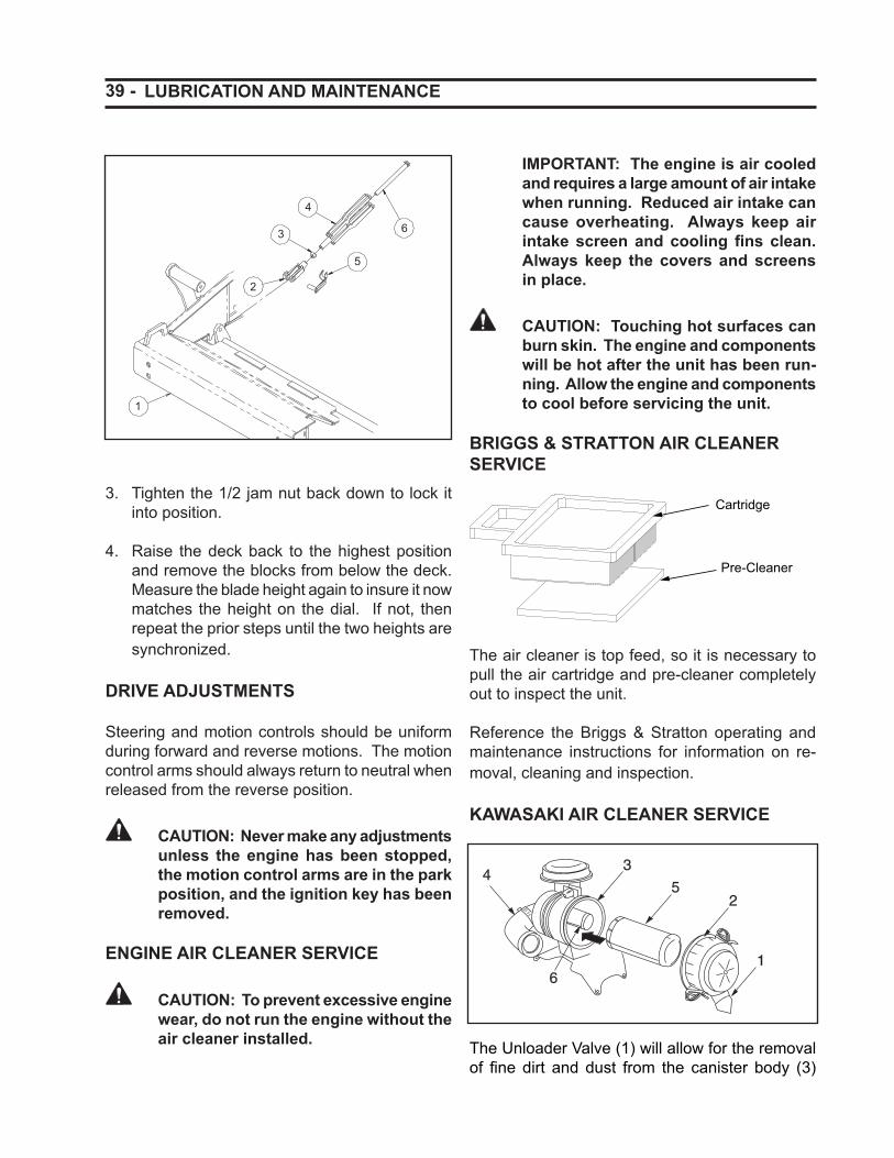
39 - LUBRICATION AND MAINTENANCE
1
2
3
4
5
6
3. Tighten the 1/2 jam nut back down to lock it into position.
4. Raise the deck back to the highest position and remove the blocks from below the deck. Measure the blade height again to insure it now matches the height on the dial. If not, then repeat the prior steps until the two heights are synchronized.
DRIVE ADJUSTMENTS
Steering and motion controls should be uniform during forward and reverse motions. The motion control arms should always return to neutral when released from the reverse position.
CAUTION: Never make any adjustments unless the engine has been stopped, the motion control arms are in the park position, and the ignition key has been removed.
ENGINE AIR CLEANER SERVICE
CAUTION: To prevent excessive engine wear, do not run the engine without the air cleaner installed.
IMPORTANT: The engine is air cooled and requires a large amount of air intake when running. Reduced air intake can cause overheating. Always keep air intake screen and cooling fi ns clean. Always keep the covers and screens in place.
CAUTION: Touching hot surfaces can burn skin. The engine and components will be hot after the unit has been run-ning. Allow the engine and components to cool before servicing the unit.
BRIGGS & STRATTON AIR CLEANER SERVICE
Cartridge
Pre-Cleaner
The air cleaner is top feed, so it is necessary to pull the air cartridge and pre-cleaner completely out to inspect the unit.
Reference the Briggs & Stratton operating and maintenance instructions for information on re-moval, cleaning and inspection.
KAWASAKI AIR CLEANER SERVICE
1
2
34
5
6
The Unloader Valve (1) will allow for the removal of fi ne dirt and dust from the canister body (3)
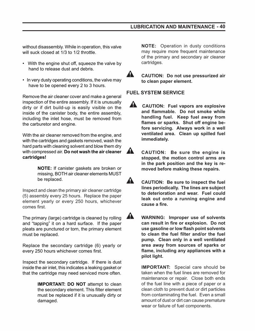
- 40 LUBRICATION AND MAINTENANCE
without disassembly. While in operation, this valve will suck closed at 1/3 to 1/2 throttle.
• With the engine shut off, squeeze the valve by hand to release dust and debris.
• In very dusty operating conditions, the valve may have to be opened every 2 to 3 hours.
Remove the air cleaner cover and make a general inspection of the entire assembly. If it is unusually dirty or if dirt build-up is easily visible on the inside of the canister body, the entire assembly, including the inlet hose, must be removed from the carburetor and engine.
With the air cleaner removed from the engine, and with the cartridges and gaskets removed, wash the hard parts with cleaning solvent and blow them dry with compressed air. Do not wash the air cleaner cartridges!
NOTE: If canister gaskets are broken or missing, BOTH air cleaner elements MUST be replaced.
Inspect and clean the primary air cleaner cartridge (5) assembly every 25 hours. Replace the paper element yearly or every 250 hours, whichever comes fi rst.
The primary (large) cartridge is cleaned by rolling and “tapping” it on a hard surface. If the paper pleats are punctured or torn, the primary element must be replaced.
Replace the secondary cartridge (6) yearly or every 250 hours whichever comes fi rst.
Inspect the secondary cartridge. If there is dust inside the air inlet, this indicates a leaking gasket or that the cartridge may need serviced more often.
IMPORTANT: DO NOT attempt to clean the secondary element. This fi lter element must be replaced if it is unusually dirty or damaged.
NOTE: Operation in dusty conditions may require more frequent maintenance of the primary and secondary air cleaner cartridges.
CAUTION: Do not use pressurized air to clean paper element.
FUEL SYSTEM SERVICE
CAUTION: Fuel vapors are explosive and fl ammable. Do not smoke while handling fuel. Keep fuel away from fl ames or sparks. Shut off engine be-fore servicing. Always work in a well ventilated area. Clean up spilled fuel immediately.
CAUTION: Be sure the engine is stopped, the motion control arms are in the park position and the key is re-moved before making these repairs.
CAUTION: Be sure to inspect the fuel lines periodically. The lines are subject to deterioration and wear. Fuel could leak out onto a running engine and cause a fi re.
WARNING: Improper use of solvents can result in fi re or explosion. Do not use gasoline or low fl ash point solvents to clean the fuel fi lter and/or the fuel pump. Clean only in a well ventilated area away from sources of sparks or fl ame, including any appliances with a pilot light.
IMPORTANT: Special care should be taken when the fuel lines are removed for maintenance or repair. Close both ends of the fuel line with a piece of paper or a clean cloth to prevent dust or dirt particles from contaminating the fuel. Even a small amount of dust or dirt can cause premature wear or failure of fuel components.
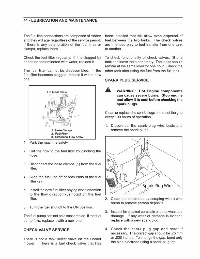
41 -
The fuel line connections are composed of rubber and they will age regardless of the service period. If there is any deterioration of the fuel lines or clamps, replace them.
Check the fuel fi lter regularly. If it is clogged by debris or contaminated with water, replace it.
The fuel fi lter cannot be disassembled. If the fuel fi lter becomes clogged, replace it with a new one.
LH Rear View
12
3
1. Hose Clamps1. Hose Clamps2. Fuel Filter2. Fuel Filter3. Directional Flow Arrow3. Directional Flow Arrow
1. Park the machine safely.
2. Cut the fl ow to the fuel fi lter by pinching the hose.
3. Disconnect the hose clamps (1) from the fuel fi lter.
4. Slide the fuel line off of both ends of the fuel fi lter (2).
5. Install the new fuel fi lter paying close attention to the flow direction (3) noted on the fuel fi lter.
6. Turn the fuel shut off to the ON position.
The fuel pump can not be disassembled. If the fuel pump fails, replace it with a new one.
CHECK VALVE SERVICE
There is not a tank select valve on the Hornet mower. There is a fuel check valve that has
LUBRICATION AND MAINTENANCE
been installed that will allow even dispersal of fuel between the two tanks. The check valves are intended only to fuel transfer from one tank to another.
To check functionality of check valves, fi ll one tank and leave the other empty. The tanks should remain at the same level for one hour. Check the other tank after using the fuel from the full tank.
SPARK PLUG SERVICE
WARNING: Hot Engine components can cause severe burns. Stop engine and allow it to cool before checking the spark plugs.
Clean or replace the spark plugs and reset the gap every 100 hours of operation.
1. Disconnect the spark plug wire leads and remove the spark plugs.
2. Clean the electrodes by scraping with a wire brush to remove carbon deposits.
3. Inspect for cracked porcelain or other wear and damage. If any wear or damage is evident, replace with a new spark plug.
4. Check the spark plug gap and reset if necessary. The correct gap should be .75 mm or .030 inches. To change the gap, bend only the side electrode using a spark plug tool.
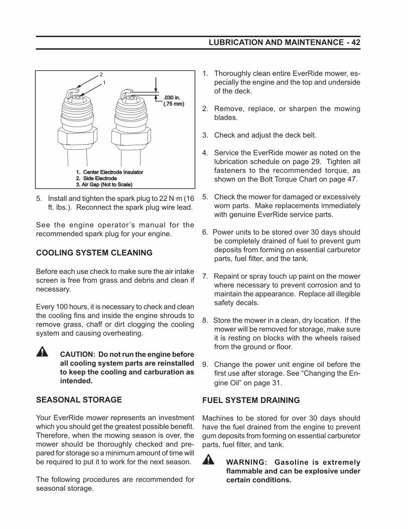
- 42
12
1. Center Electrode Insulator1. Center Electrode Insulator2. Side Electrode2. Side Electrode3. Air Gap (Not to Scale)3. Air Gap (Not to Scale)
.030 in..030 in.(.75 mm)(.75 mm)
5. Install and tighten the spark plug to 22 N·m (16 ft. lbs.). Reconnect the spark plug wire lead.
See the engine operator ’s manual for the recommended spark plug for your engine.
COOLING SYSTEM CLEANING
Before each use check to make sure the air intake screen is free from grass and debris and clean if necessary.
Every 100 hours, it is necessary to check and clean the cooling fi ns and inside the engine shrouds to remove grass, chaff or dirt clogging the cooling system and causing overheating.
CAUTION: Do not run the engine before all cooling system parts are reinstalled to keep the cooling and carburation as intended.
SEASONAL STORAGE
Your EverRide mower represents an investment which you should get the greatest possible benefi t. Therefore, when the mowing season is over, the mower should be thoroughly checked and pre-pared for storage so a minimum amount of time will be required to put it to work for the next season.
The following procedures are recommended for seasonal storage.
1. Thoroughly clean entire EverRide mower, es-pecially the engine and the top and underside of the deck.
2. Remove, replace, or sharpen the mowing blades.
3. Check and adjust the deck belt.
4. Service the EverRide mower as noted on the lubrication schedule on page 29. Tighten all fasteners to the recommended torque, as shown on the Bolt Torque Chart on page 47.
5. Check the mower for damaged or excessively worn parts. Make replacements immediately with genuine EverRide service parts.
6. Power units to be stored over 30 days should be completely drained of fuel to prevent gum deposits from forming on essential carburetor parts, fuel fi lter, and the tank.
7. Repaint or spray touch up paint on the mower
where necessary to prevent corrosion and to maintain the appearance. Replace all illegible safety decals.
8. Store the mower in a clean, dry location. If the mower will be removed for storage, make sure it is resting on blocks with the wheels raised from the ground or fl oor.
9. Change the power unit engine oil before the fi rst use after storage. See “Changing the En-gine Oil” on page 31.
FUEL SYSTEM DRAINING
Machines to be stored for over 30 days should have the fuel drained from the engine to prevent gum deposits from forming on essential carburetor parts, fuel fi lter, and tank.
WARNING: Gasoline is extremely fl ammable and can be explosive under certain conditions.
LUBRICATION AND MAINTENANCE
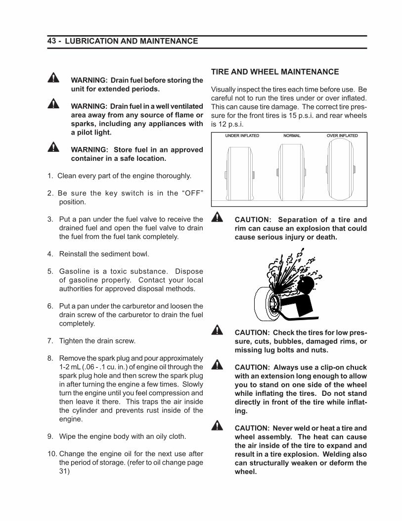
43 -
WARNING: Drain fuel before storing the unit for extended periods.
WARNING: Drain fuel in a well ventilated area away from any source of fl ame or sparks, including any appliances with a pilot light.
WARNING: Store fuel in an approved container in a safe location.
1. Clean every part of the engine thoroughly.
2. Be sure the key switch is in the “OFF” position.
3. Put a pan under the fuel valve to receive the drained fuel and open the fuel valve to drain the fuel from the fuel tank completely.
4. Reinstall the sediment bowl.
5. Gasoline is a toxic substance. Dispose of gasoline properly. Contact your local authorities for approved disposal methods.
6. Put a pan under the carburetor and loosen the drain screw of the carburetor to drain the fuel completely.
7. Tighten the drain screw.
8. Remove the spark plug and pour approximately 1-2 mL (.06 - .1 cu. in.) of engine oil through the spark plug hole and then screw the spark plug in after turning the engine a few times. Slowly turn the engine until you feel compression and then leave it there. This traps the air inside the cylinder and prevents rust inside of the engine.
9. Wipe the engine body with an oily cloth.
10. Change the engine oil for the next use after the period of storage. (refer to oil change page 31)
TIRE AND WHEEL MAINTENANCE
Visually inspect the tires each time before use. Be careful not to run the tires under or over infl ated. This can cause tire damage. The correct tire pres-sure for the front tires is 15 p.s.i. and rear wheels is 12 p.s.i.
UNDER INFLATEDUNDER INFLATED OVER INFLATEDOVER INFLATEDNORMALNORMAL
CAUTION: Separation of a tire and rim can cause an explosion that could cause serious injury or death.
CAUTION: Check the tires for low pres-sure, cuts, bubbles, damaged rims, or missing lug bolts and nuts.
CAUTION: Always use a clip-on chuck with an extension long enough to allow you to stand on one side of the wheel while infl ating the tires. Do not stand directly in front of the tire while infl at-ing.
CAUTION: Never weld or heat a tire and wheel assembly. The heat can cause the air inside of the tire to expand and result in a tire explosion. Welding also can structurally weaken or deform the wheel.
LUBRICATION AND MAINTENANCE
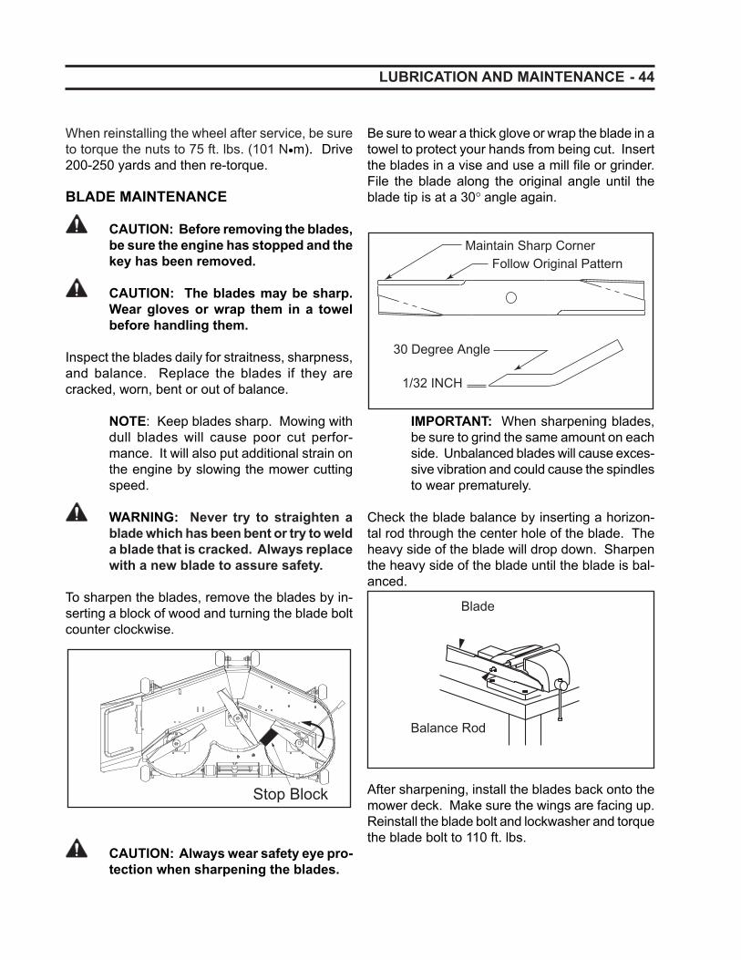
- 44 LUBRICATION AND MAINTENANCE
When reinstalling the wheel after service, be sure to torque the nuts to 75 ft. lbs. (101 N•m). Drive 200-250 yards and then re-torque.
BLADE MAINTENANCE
CAUTION: Before removing the blades, be sure the engine has stopped and the key has been removed.
CAUTION: The blades may be sharp. Wear gloves or wrap them in a towel before handling them.
Inspect the blades daily for straitness, sharpness, and balance. Replace the blades if they are cracked, worn, bent or out of balance.
NOTE: Keep blades sharp. Mowing with dull blades will cause poor cut perfor-mance. It will also put additional strain on the engine by slowing the mower cutting speed.
WARNING: Never try to straighten a blade which has been bent or try to weld a blade that is cracked. Always replace with a new blade to assure safety.
To sharpen the blades, remove the blades by in-serting a block of wood and turning the blade bolt counter clockwise.
Stop Block
CAUTION: Always wear safety eye pro-tection when sharpening the blades.
Be sure to wear a thick glove or wrap the blade in a towel to protect your hands from being cut. Insert the blades in a vise and use a mill fi le or grinder. File the blade along the original angle until the blade tip is at a 30° angle again.
1/32 INCH
30 Degree Angle
Follow Original PatternMaintain Sharp Corner
IMPORTANT: When sharpening blades, be sure to grind the same amount on each side. Unbalanced blades will cause exces-sive vibration and could cause the spindles to wear prematurely.
Check the blade balance by inserting a horizon-tal rod through the center hole of the blade. The heavy side of the blade will drop down. Sharpen the heavy side of the blade until the blade is bal-anced.
Blade
Balance Rod
After sharpening, install the blades back onto the mower deck. Make sure the wings are facing up. Reinstall the blade bolt and lockwasher and torque the blade bolt to 110 ft. lbs.
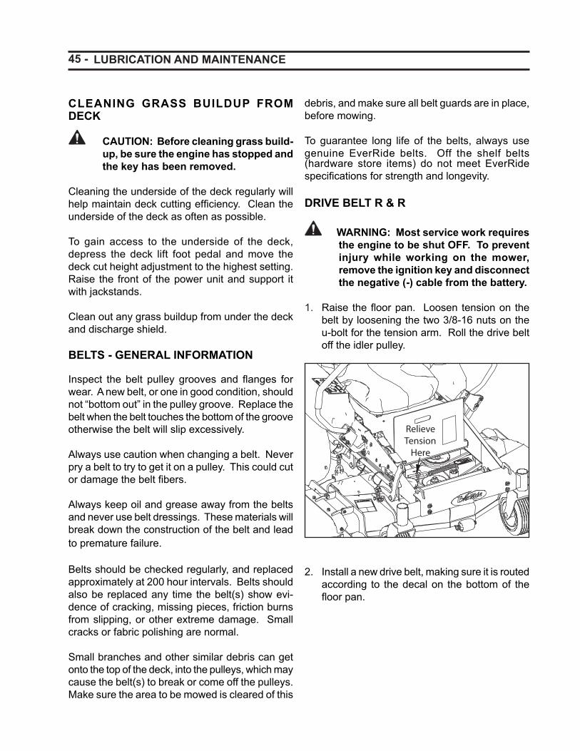
45 - LUBRICATION AND MAINTENANCE
CLEANING GRASS BUILDUP FROM DECK
CAUTION: Before cleaning grass build-up, be sure the engine has stopped and the key has been removed.
Cleaning the underside of the deck regularly will help maintain deck cutting effi ciency. Clean the underside of the deck as often as possible.
To gain access to the underside of the deck, depress the deck lift foot pedal and move the deck cut height adjustment to the highest setting. Raise the front of the power unit and support it with jackstands.
Clean out any grass buildup from under the deck and discharge shield.
BELTS - GENERAL INFORMATION
Inspect the belt pulley grooves and fl anges for wear. A new belt, or one in good condition, should not “bottom out” in the pulley groove. Replace the belt when the belt touches the bottom of the groove otherwise the belt will slip excessively.
Always use caution when changing a belt. Never pry a belt to try to get it on a pulley. This could cut or damage the belt fi bers.
Always keep oil and grease away from the belts and never use belt dressings. These materials will break down the construction of the belt and lead to premature failure.
Belts should be checked regularly, and replaced approximately at 200 hour intervals. Belts should also be replaced any time the belt(s) show evi-dence of cracking, missing pieces, friction burns from slipping, or other extreme damage. Small cracks or fabric polishing are normal.
Small branches and other similar debris can get onto the top of the deck, into the pulleys, which may cause the belt(s) to break or come off the pulleys. Make sure the area to be mowed is cleared of this
debris, and make sure all belt guards are in place, before mowing.
To guarantee long life of the belts, always use genuine EverRide belts. Off the shelf belts (hardware store items) do not meet EverRide specifi cations for strength and longevity.
DRIVE BELT R & R
WARNING: Most service work requires the engine to be shut OFF. To prevent injury while working on the mower, remove the ignition key and disconnect the negative (-) cable from the battery.
1. Raise the fl oor pan. Loosen tension on the belt by loosening the two 3/8-16 nuts on the u-bolt for the tension arm. Roll the drive belt off the idler pulley.
2. Install a new drive belt, making sure it is routed according to the decal on the bottom of the fl oor pan.
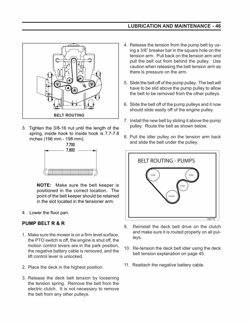
- 46
BELT ROUTING
3. Tighten the 3/8-16 nut until the length of the spring, inside hook to inside hook is 7.7-7.8 inches (196 mm - 198 mm).
7.7007.7007.8007.800
NOTE: Make sure the belt keeper is positioned in the correct location. The point of the belt keeper should be retained in the slot located in the tensioner arm.
4. Lower the fl oor pan.
PUMP BELT R & R
1. Make sure the mower is on a fi rm level surface, the PTO switch is off, the engine is shut off, the motion control levers are in the park position, the negative battery cable is removed, and the lift control lever is unlocked.
2. Place the deck in the highest position.
3. Release the deck belt tension by loosening the tension spring. Remove the belt from the electric clutch. It is not necessary to remove the belt from any other pulleys.
4. Release the tension from the pump belt by us-ing a 3/8” breaker bar in the square hole on the tension arm. Pull back on the tension arm and pull the belt out from behind the pulley. Use caution when releasing the belt tension arm as there is pressure on the arm.
5. Slide the belt off of the pump pulley. The belt will have to be slid above the pump pulley to allow the belt to be removed from the other pulleys.
6. Slide the belt off of the pump pulleys and it now should slide easily off of the engine pulley.
7. Install the new belt by sliding it above the pump pulley. Route the belt as shown below.
8. Pull the idler pulley on the tension arm back and slide the belt under the pulley.
9. Reinstall the deck belt drive on the clutch and make sure it is routed properly on all pul-leys.
10. Re-tension the deck belt idler using the deck belt tension explanation on page 45.
11. Reattach the negative battery cable.
LUBRICATION AND MAINTENANCE
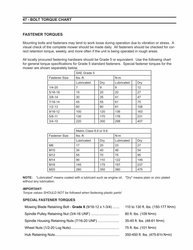
47 - BOLT TORQUE CHART
FASTENER TORQUES
Mounting bolts and fasteners may tend to work loose during operation due to vibration or stress. A visual check of the complete mower should be made daily. All fasteners should be checked for cor-rect retention torque, weekly, and more often if the unit is being operated in rough areas.
All locally procured fastening hardware should be Grade 5 or equivalent. Use the following chart for general torque specifi cations for Grade 5 standard fasteners. Special fastener torques for the mower are shown separately below.
SAE Grade 5Fastener Size lbs.-ft. N-m
Lubricated Dry Lubricated Dry1/4-20 7 9 9 125/16-18 15 20 20 273/8-14 30 35 41 477/16-14 45 55 61 751/2-13 60 80 81 1089/16-12 100 120 136 1635/8-11 130 170 176 2313/4-10 220 300 298 407
Metric Class 8.8 or 9.8Fastener Size lbs.-ft. N-m
Lubricated Dry Lubricated DryM8 17 20 23 27M10 34 40 46 54M12 55 70 75 95M14 90 110 122 149M16 145 175 197 237M20 280 350 380 475
NOTE: “Lubricated" means coated with a lubricant such as engine oil. "Dry" means plain or zinc plated without any lubrication. IMPORTANT: Torque values SHOULD NOT be followed when fastening plastic parts!
SPECIAL FASTENER TORQUES
Mowing Blade Retaining Bolt - Grade 8 (9/16-12 x 1-3/4) ....... 110 to 130 ft. lbs. (150-177 N�m)
Spindle Pulley Retaining Nut (3/4-16 UNF) ............................. 80 ft. lbs. (109 N�m)
Spindle Housing Retaining Nuts (7/16-20 UNF) ...................... 35-45 ft. lbs. (48-61 N�m)
Wheel Nuts (1/2-20 Lug Nuts).................................................. 75 ft. lbs. (101 N�m)
Hub Retaining Nuts................................................................... 350-450 ft. lbs. (475-610 N�m)
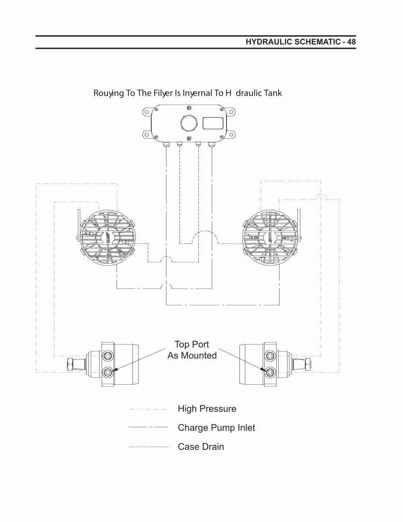
- 48 HYDRAULIC SCHEMATIC
Top PortAs Mounted
Case Drain
High Pressure
Charge Pump Inlet
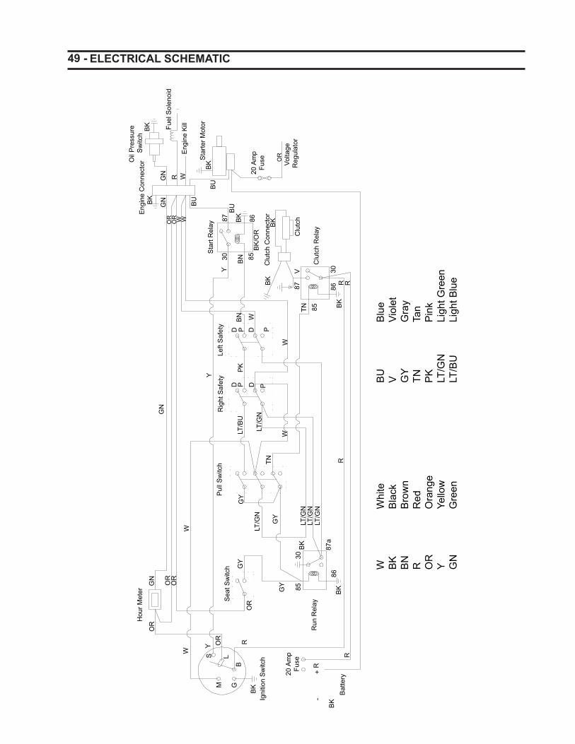
49 - ELECTRICAL SCHEMATIC
-R
+
W
GB
S L
W
PP
PD DW
PD D
V
R W
Y
Y
W W
R
R
W
W
hite
BK
Bla
ckB
N
B
row
nR
Red
OR
Ora
nge
Y
Yello
wG
N
G
reen
BU
Blu
eV
Viol
etG
Y
Gra
yTN
Tan
PK
Pin
k LT
/GN
Li
ght G
reen
LT/B
U
Ligh
t Blu
e
Hou
r Met
er
OR
GN
OR
OR
GN
Y
Rig
ht S
afet
yLe
ft S
afet
y
W
Sea
t Sw
itch
W
M
BK
20 A
mp
Fuse
OR
OR
LT/G
N
GY
GY
GYP
ull S
witc
h
BK
Bat
tery
8530
BK
LT/G
NLT
/GN
LT/G
N87
a86
BK
R
GY
TNLT
/GN
LT/B
UP
KB
N
TN 85
87BK
Clu
tch
Clu
tch
Con
nect
orB
K
BK
/OR
8685BN30
87 BK
BU
BK
8630
RR
Eng
ine
Con
nect
or
OR
OR
BU
GN
GN
Oil
Pre
ssur
e S
witc
hB
K Fuel
Sol
enoi
d
Eng
ine
Kill
Sta
rter M
otor
BK
BU
20 A
mp
Fuse Vo
ltage
R
egul
ator
BK
Igni
tion
Sw
itch
Sta
rt R
elay
Clu
tch
Rel
ay
OR
Run
Rel
ay
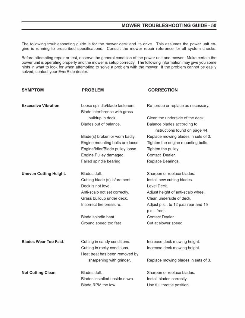
- 50 MOWER TROUBLESHOOTING GUIDE
The following troubleshooting guide is for the mower deck and its drive. This assumes the power unit en-gine is running to prescribed specifi cations. Consult the mower repair reference for all system checks.
Before attempting repair or test, observe the general condition of the power unit and mower. Make certain the power unit is operating properly and the mower is setup correctly. The following information may give you some hints in what to look for when attempting to solve a problem with the mower. If the problem cannot be easily solved, contact your EverRide dealer.
SYMPTOM PROBLEM CORRECTION
Excessive Vibration. Loose spindle/blade fasteners. Re-torque or replace as necessary. Blade interference with grass buildup in deck. Clean the underside of the deck. Blades out of balance. Balance blades according to instructions found on page 44. Blade(s) broken or worn badly. Replace mowing blades in sets of 3. Engine mounting bolts are loose. Tighten the engine mounting bolts. Engine/Idler/Blade pulley loose. Tighten the pulley. Engine Pulley damaged. Contact Dealer. Failed spindle bearing Replace Bearings. Uneven Cutting Height. Blades dull. Sharpen or replace blades. Cutting blade (s) is/are bent. Install new cutting blades. Deck is not level. Level Deck. Anti-scalp not set correctly. Adjust height of anti-scalp wheel. Grass buildup under deck. Clean underside of deck. Incorrect tire pressure. Adjust p.s.i. to 12 p.s.i rear and 15 p.s.i. front. Blade spindle bent. Contact Dealer. Ground speed too fast Cut at slower speed.
Blades Wear Too Fast. Cutting in sandy conditions. Increase deck mowing height. Cutting in rocky conditions. Increase deck mowing height. Heat treat has been removed by sharpening with grinder. Replace mowing blades in sets of 3. Not Cutting Clean. Blades dull. Sharpen or replace blades. Blades installed upside down. Install blades correctly. Blade RPM too low. Use full throttle position.

51 - MOWER TROUBLESHOOTING GUIDE
Mower deck not level. See cutting heights (page 25). Tires under infl ated (12 p.s.i. rear and 15 p.s.i. front). Mower tires mashing grass. Too wet or lush to mow. Reverse direction and re-mow the area. Ground speed too fast. Reduce ground speed. Excessive grass buildup under mower deck. Clean underside of deck.
Streaking or Windrow Conditions in Swath. Blades dull. Sharpen or replace blades. Blades installed upside down. Install blades correctly. Conditions too wet for mowing. Allow grass to dry before mowing. Excessive grass buildup under mower deck. Clean underside of deck. Ground speed too fast for conditions. Operate at slower speeds.
Blades Don’t Rotate. Deck belt is worn, loose Install new deck belt. or broken. Deck belt off pulley. Reinstall deck belt. Clutch not operating. Inspect. Replace if necessary. Mower Loads Power Unit. Engine RPM too low. Use full throttle position. Ground speed too fast. Reduce ground speed. Excessive grass buildup under mower deck. Clean underside of deck.
Excessive Noise. Grass and lawn debris buildup under the deck will cause excessive noise as the mower blades will contact the eventual hardened buildup. Clean the underside of the deck regularly, especially if the mowing conditions were wet or extremely lush.

- 52 POWER UNIT TROUBLESHOOTING GUIDE
Engine Idling Poorly Carburetor adjusted incorrectly. Readjust carburetor. Improper spark plug gap. Check and re-gap plugs.
Engine Backfi res Carburetor adjusted incorrectly. Contact dealer.
Engine Runs But Drive belt loose or broken. Tighten or replace the drive belt. Won’t Move Hydrostatic reservoir oil low. Refi ll reservoir. Pump bypass valve open. Put in closed position. Hydrostatic oil fi lter plugged. Replace fi lter. Damaged pump or motor. Contact dealer.
Power Unit Loses Power or Hydrostatic oil reserve too low. Refi ll reservoir.Hydrostat System Overheats Pump or motor damaged. Contact dealer. Hydrostatic oil reservoir blowing oil out of cap. Overfi ll or water contaminated.
Loss of Power or System Restrictions in air cleaner. Service air cleaner.Will Not Operate in Either Poor compression. Contact dealer.Direction Steering linkage needs adjustment. Contact dealer. Hydraulic bypass valve open. Close the bypass valve. Pump belt broken or worn. Replace belt. Pump belt off of pulley. Reinstall belt on pulley. Engine Overheating Air intake screen clogged. Service air intake screen. Cooling fi ns clogged. Clean fi ns.
Engine Stalling While Operator not in seat. Sit on seat.Blades are Engaged Faulty safety system. Contact dealer. Spindle bearing failure. Contact dealer. Blades locked by foreign matter. Clean underside of deck.
Low Engine Oil Pressure Low oil level. Add oil. Oil diluted or too light. Change oil and locate source of contamination.
High Oil Consumption Improper Oil Viscosity. Use SAE30 oil whenever possible Numerous other possible causes. Contact dealer.
Engine Will Not Turn Over Dead battery. Charge unit or jump start. Bad ground connection. Correct the connection. Poor terminal connection at battery. Correct the connection. Poor wiring harness connections. Correct the connection. Bad park switch. Contact dealer. Bad PTO switch. Contact dealer. Motion control arms not in park position. Put arms in park. PTO switch engaged. Disengage PTO switch. Operator not in seat. Sit in seat. Blown Fuse. Replace fuse.
SYMPTOM PROBLEM CORRECTION
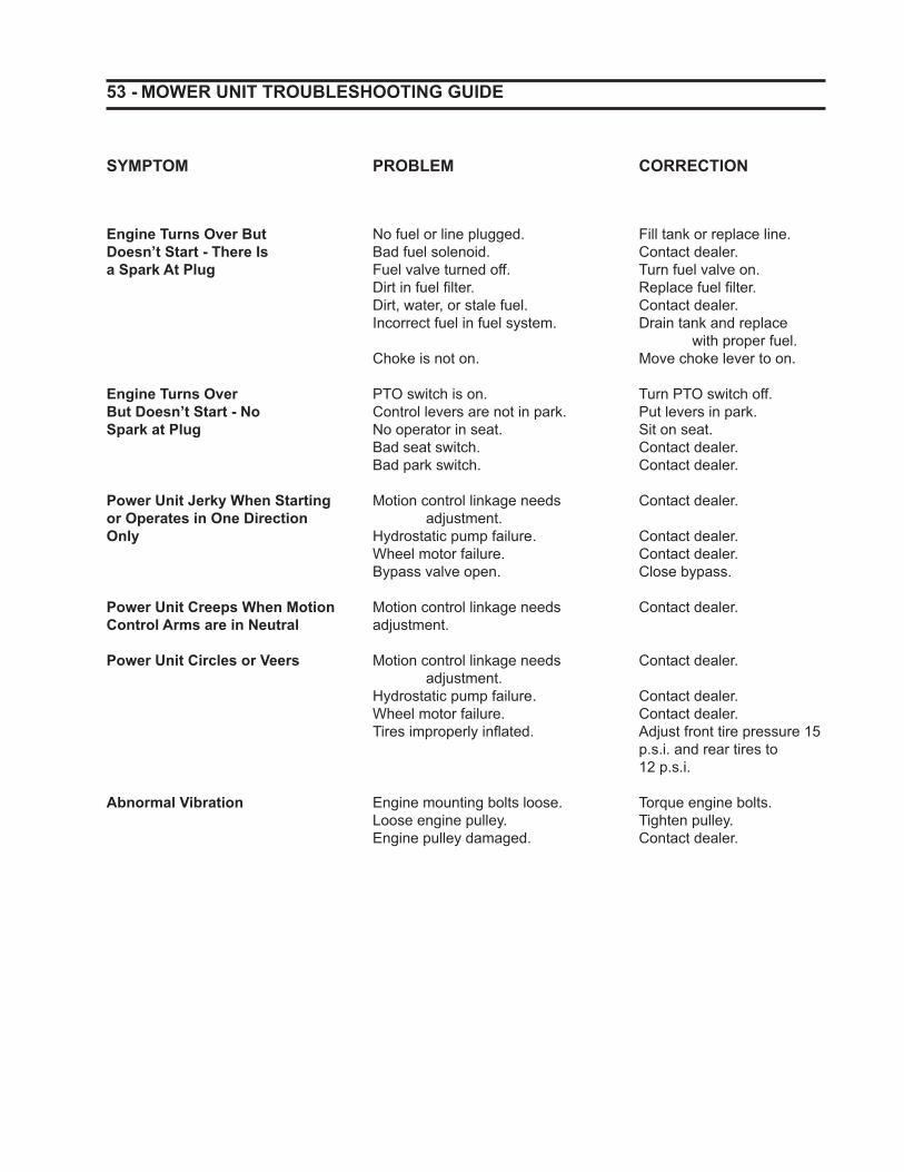
53 - MOWER UNIT TROUBLESHOOTING GUIDE
Engine Turns Over But No fuel or line plugged. Fill tank or replace line. Doesn’t Start - There Is Bad fuel solenoid. Contact dealer.a Spark At Plug Fuel valve turned off. Turn fuel valve on. Dirt in fuel fi lter. Replace fuel fi lter. Dirt, water, or stale fuel. Contact dealer. Incorrect fuel in fuel system. Drain tank and replace with proper fuel. Choke is not on. Move choke lever to on.
Engine Turns Over PTO switch is on. Turn PTO switch off.But Doesn’t Start - No Control levers are not in park. Put levers in park. Spark at Plug No operator in seat. Sit on seat. Bad seat switch. Contact dealer. Bad park switch. Contact dealer. Power Unit Jerky When Starting Motion control linkage needs Contact dealer. or Operates in One Direction adjustment.Only Hydrostatic pump failure . Contact dealer. Wheel motor failure. Contact dealer. Bypass valve open. Close bypass.
Power Unit Creeps When Motion Motion control linkage needs Contact dealer.Control Arms are in Neutral adjustment. Power Unit Circles or Veers Motion control linkage needs Contact dealer. adjustment. Hydrostatic pump failure . Contact dealer. Wheel motor failure. Contact dealer. Tires improperly infl ated. Adjust front tire pressure 15 p.s.i. and rear tires to 12 p.s.i.
Abnormal Vibration Engine mounting bolts loose. Torque engine bolts. Loose engine pulley. Tighten pulley. Engine pulley damaged. Contact dealer.
SYMPTOM PROBLEM CORRECTION
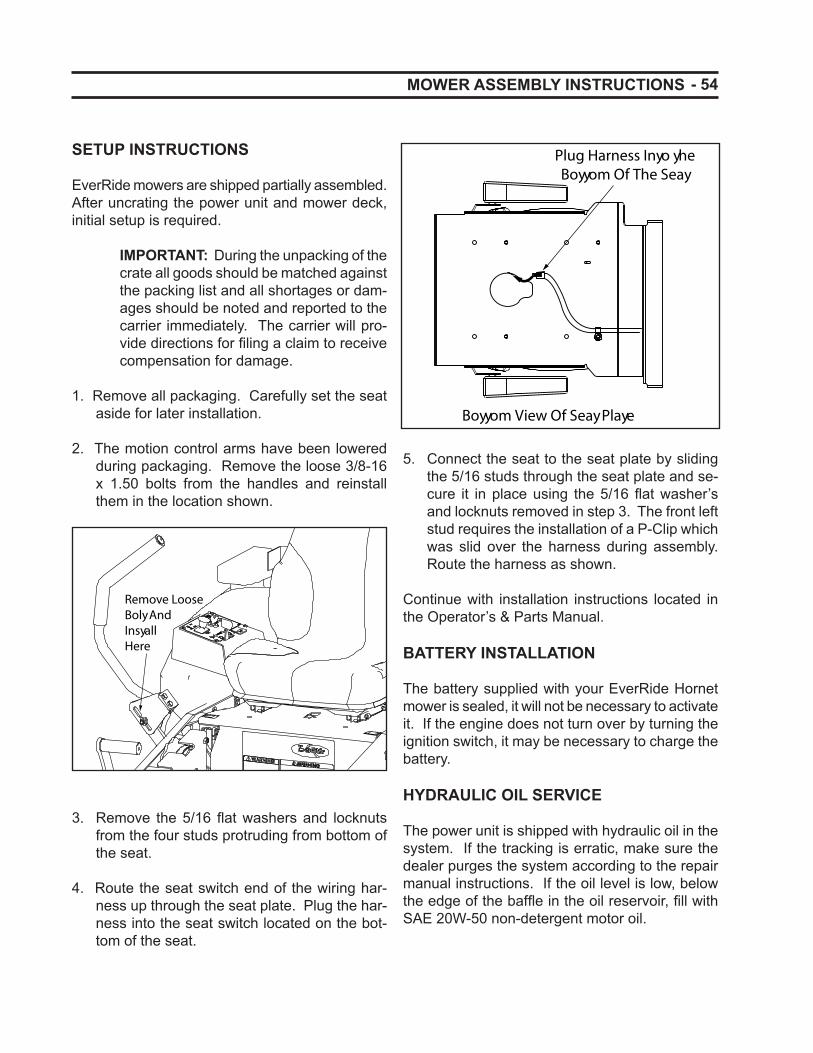
- 54
5. Connect the seat to the seat plate by sliding the 5/16 studs through the seat plate and se-cure it in place using the 5/16 fl at washer’s and locknuts removed in step 3. The front left stud requires the installation of a P-Clip which was slid over the harness during assembly. Route the harness as shown.
Continue with installation instructions located in the Operator’s & Parts Manual.
BATTERY INSTALLATION
The battery supplied with your EverRide Hornet mower is sealed, it will not be necessary to activate it. If the engine does not turn over by turning the ignition switch, it may be necessary to charge the battery.
HYDRAULIC OIL SERVICE
The power unit is shipped with hydraulic oil in the system. If the tracking is erratic, make sure the dealer purges the system according to the repair manual instructions. If the oil level is low, below the edge of the baffl e in the oil reservoir, fi ll with SAE 20W-50 non-detergent motor oil.
SETUP INSTRUCTIONS
EverRide mowers are shipped partially assembled. After uncrating the power unit and mower deck, initial setup is required.
IMPORTANT: During the unpacking of the crate all goods should be matched against the packing list and all shortages or dam-ages should be noted and reported to the carrier immediately. The carrier will pro-vide directions for fi ling a claim to receive compensation for damage.
1. Remove all packaging. Carefully set the seat aside for later installation.
2. The motion control arms have been lowered during packaging. Remove the loose 3/8-16 x 1.50 bolts from the handles and reinstall them in the location shown.
3. Remove the 5/16 fl at washers and locknuts from the four studs protruding from bottom of the seat.
4. Route the seat switch end of the wiring har-ness up through the seat plate. Plug the har-ness into the seat switch located on the bot-tom of the seat.
MOWER ASSEMBLY INSTRUCTIONS
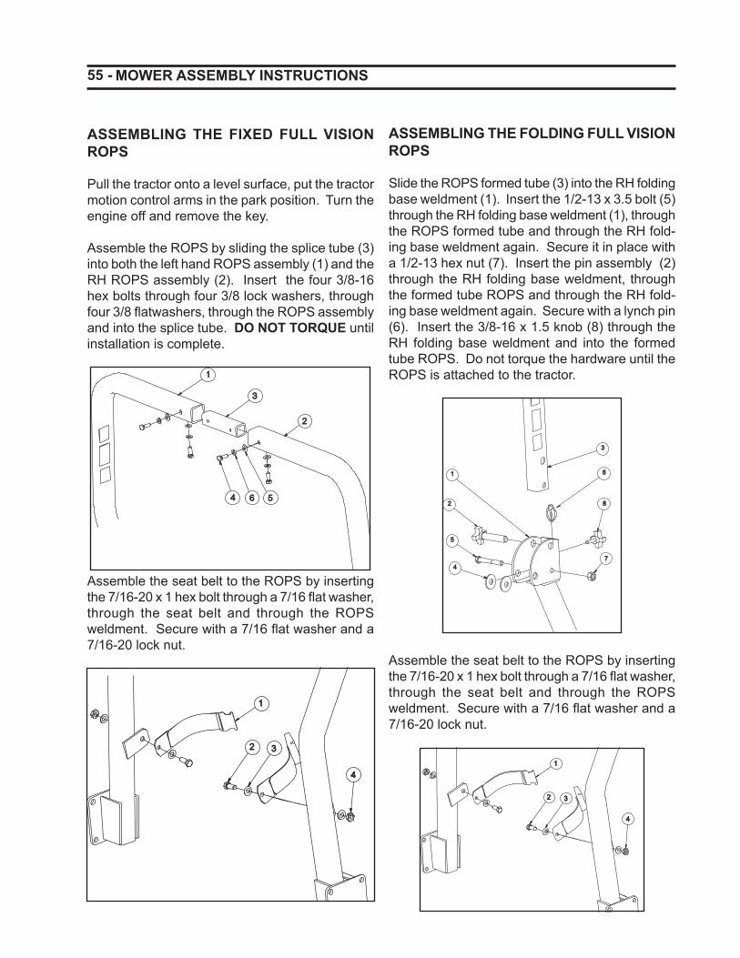
55 -
ASSEMBLING THE FIXED FULL VISION ROPS
Pull the tractor onto a level surface, put the tractor motion control arms in the park position. Turn the engine off and remove the key.
Assemble the ROPS by sliding the splice tube (3) into both the left hand ROPS assembly (1) and the RH ROPS assembly (2). Insert the four 3/8-16 hex bolts through four 3/8 lock washers, through four 3/8 fl atwashers, through the ROPS assembly and into the splice tube. DO NOT TORQUE until installation is complete.
11
44 66 55
33
22
Assemble the seat belt to the ROPS by inserting the 7/16-20 x 1 hex bolt through a 7/16 fl at washer, through the seat belt and through the ROPS weldment. Secure with a 7/16 fl at washer and a 7/16-20 lock nut.
3322
11
44
MOWER ASSEMBLY INSTRUCTIONS
ASSEMBLING THE FOLDING FULL VISION ROPS
Slide the ROPS formed tube (3) into the RH folding base weldment (1). Insert the 1/2-13 x 3.5 bolt (5) through the RH folding base weldment (1), through the ROPS formed tube and through the RH fold-ing base weldment again. Secure it in place with a 1/2-13 hex nut (7). Insert the pin assembly (2) through the RH folding base weldment, through the formed tube ROPS and through the RH fold-ing base weldment again. Secure with a lynch pin (6). Insert the 3/8-16 x 1.5 knob (8) through the RH folding base weldment and into the formed tube ROPS. Do not torque the hardware until the ROPS is attached to the tractor.
77
88
6611
44
55
22
33
Assemble the seat belt to the ROPS by inserting the 7/16-20 x 1 hex bolt through a 7/16 fl at washer, through the seat belt and through the ROPS weldment. Secure with a 7/16 fl at washer and a 7/16-20 lock nut.
3322
11
44
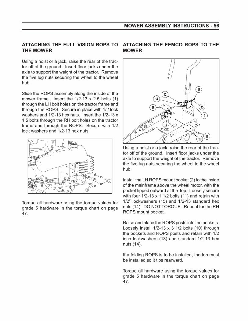
- 56
ATTACHING THE FULL VISION ROPS TO THE MOWER
Using a hoist or a jack, raise the rear of the trac-tor off of the ground. Insert fl oor jacks under the axle to support the weight of the tractor. Remove the fi ve lug nuts securing the wheel to the wheel hub.
Slide the ROPS assembly along the inside of the mower frame. Insert the 1/2-13 x 2.5 bolts (1) through the LH bolt holes on the tractor frame and through the ROPS. Secure in place with 1/2 lock washers and 1/2-13 hex nuts. Insert the 1/2-13 x 1.5 bolts through the RH bolt holes on the tractor frame and through the ROPS. Secure with 1/2 lock washers and 1/2-13 hex nuts.
1
2
Torque all hardware using the torque values for grade 5 hardware in the torque chart on page 47.
MOWER ASSEMBLY INSTRUCTIONS
ATTACHING THE FEMCO ROPS TO THE MOWER
11111111
2
1515
14141212
1414
1515
Using a hoist or a jack, raise the rear of the trac-tor off of the ground. Insert fl oor jacks under the axle to support the weight of the tractor. Remove the fi ve lug nuts securing the wheel to the wheel hub.
Install the LH ROPS mount pocket (2) to the inside of the mainframe above the wheel motor, with the pocket tipped outward at the top. Loosely secure with four 1/2-13 x 1 1/2 bolts (11) and retain with 1/2” lockwashers (15) and 1/2-13 standard hex nuts (14). DO NOT TORQUE. Repeat for the RH ROPS mount pocket.
Raise and place the ROPS posts into the pockets. Loosely install 1/2-13 x 3 1/2 bolts (10) through the pockets and ROPS posts and retain with 1/2 inch lockwashers (13) and standard 1/2-13 hex nuts (14).
If a folding ROPS is to be installed, the top must be installed so it tips rearward.
Torque all hardware using the torque values for grade 5 hardware in the torque chart on page 47.
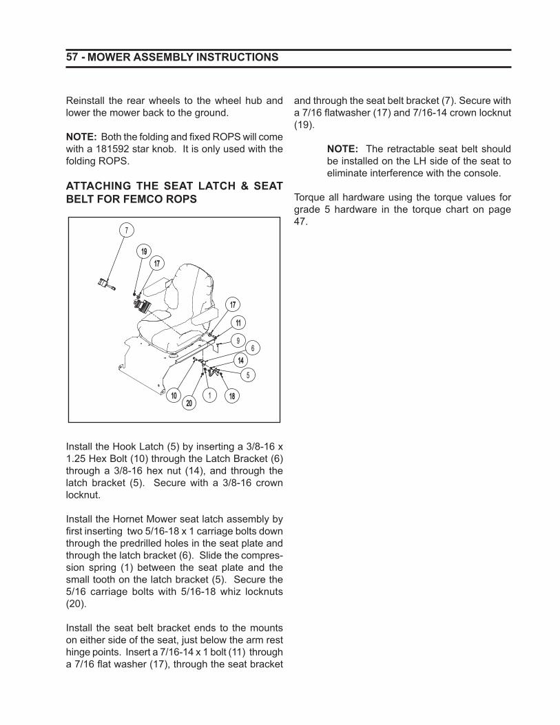
57 - MOWER ASSEMBLY INSTRUCTIONS
Reinstall the rear wheels to the wheel hub and lower the mower back to the ground.
NOTE: Both the folding and fi xed ROPS will come with a 181592 star knob. It is only used with the folding ROPS.
ATTACHING THE SEAT LATCH & SEAT BELT FOR FEMCO ROPS
7
19191717
1717
1111
1010
61414
18181
5
9
2020
Install the Hook Latch (5) by inserting a 3/8-16 x 1.25 Hex Bolt (10) through the Latch Bracket (6) through a 3/8-16 hex nut (14), and through the latch bracket (5). Secure with a 3/8-16 crown locknut.
Install the Hornet Mower seat latch assembly by fi rst inserting two 5/16-18 x 1 carriage bolts down through the predrilled holes in the seat plate and through the latch bracket (6). Slide the compres-sion spring (1) between the seat plate and the small tooth on the latch bracket (5). Secure the 5/16 carriage bolts with 5/16-18 whiz locknuts (20).
Install the seat belt bracket ends to the mounts on either side of the seat, just below the arm rest hinge points. Insert a 7/16-14 x 1 bolt (11) through a 7/16 fl at washer (17), through the seat bracket
and through the seat belt bracket (7). Secure with a 7/16 fl atwasher (17) and 7/16-14 crown locknut (19).
NOTE: The retractable seat belt should be installed on the LH side of the seat to eliminate interference with the console.
Torque all hardware using the torque values for grade 5 hardware in the torque chart on page 47.
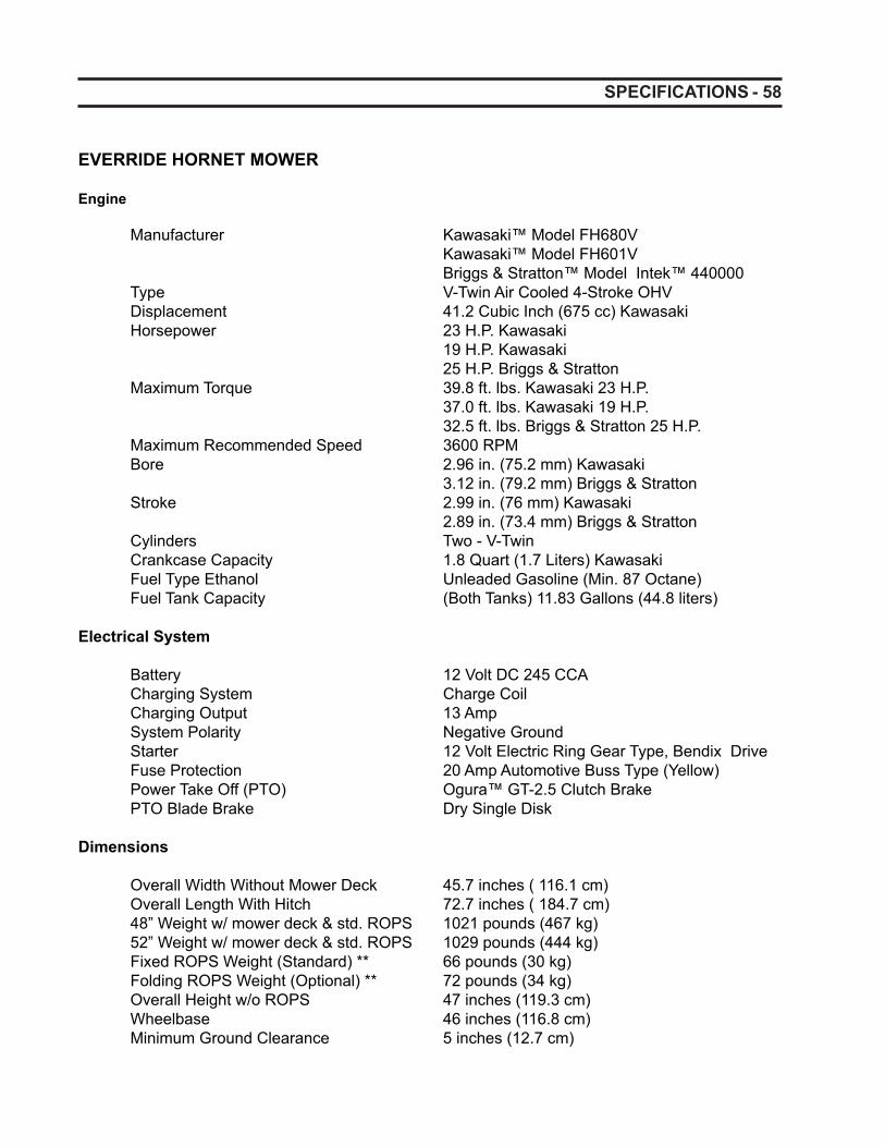
- 58 SPECIFICATIONS
EVERRIDE HORNET MOWER Engine
Manufacturer Kawasaki™ Model FH680V Kawasaki™ Model FH601V Briggs & Stratton™ Model Intek™ 440000 Type V-Twin Air Cooled 4-Stroke OHV Displacement 41.2 Cubic Inch (675 cc) Kawasaki Horsepower 23 H.P. Kawasaki 19 H.P. Kawasaki 25 H.P. Briggs & Stratton Maximum Torque 39.8 ft. lbs. Kawasaki 23 H.P. 37.0 ft. lbs. Kawasaki 19 H.P. 32.5 ft. lbs. Briggs & Stratton 25 H.P. Maximum Recommended Speed 3600 RPM Bore 2.96 in. (75.2 mm) Kawasaki 3.12 in. (79.2 mm) Briggs & Stratton Stroke 2.99 in. (76 mm) Kawasaki 2.89 in. (73.4 mm) Briggs & Stratton Cylinders Two - V-Twin Crankcase Capacity 1.8 Quart (1.7 Liters) Kawasaki Fuel Type Ethanol Unleaded Gasoline (Min. 87 Octane) Fuel Tank Capacity (Both Tanks) 11.83 Gallons (44.8 liters)
Electrical System
Battery 12 Volt DC 245 CCA Charging System Charge Coil Charging Output 13 Amp System Polarity Negative Ground Starter 12 Volt Electric Ring Gear Type, Bendix Drive Fuse Protection 20 Amp Automotive Buss Type (Yellow) Power Take Off (PTO) Ogura™ GT-2.5 Clutch Brake PTO Blade Brake Dry Single Disk
Dimensions
Overall Width Without Mower Deck 45.7 inches ( 116.1 cm) Overall Length With Hitch 72.7 inches ( 184.7 cm) 48” Weight w/ mower deck & std. ROPS 1021 pounds (467 kg) 52” Weight w/ mower deck & std. ROPS 1029 pounds (444 kg) Fixed ROPS Weight (Standard) ** 66 pounds (30 kg) Folding ROPS Weight (Optional) ** 72 pounds (34 kg) Overall Height w/o ROPS 47 inches (119.3 cm) Wheelbase 46 inches (116.8 cm) Minimum Ground Clearance 5 inches (12.7 cm)
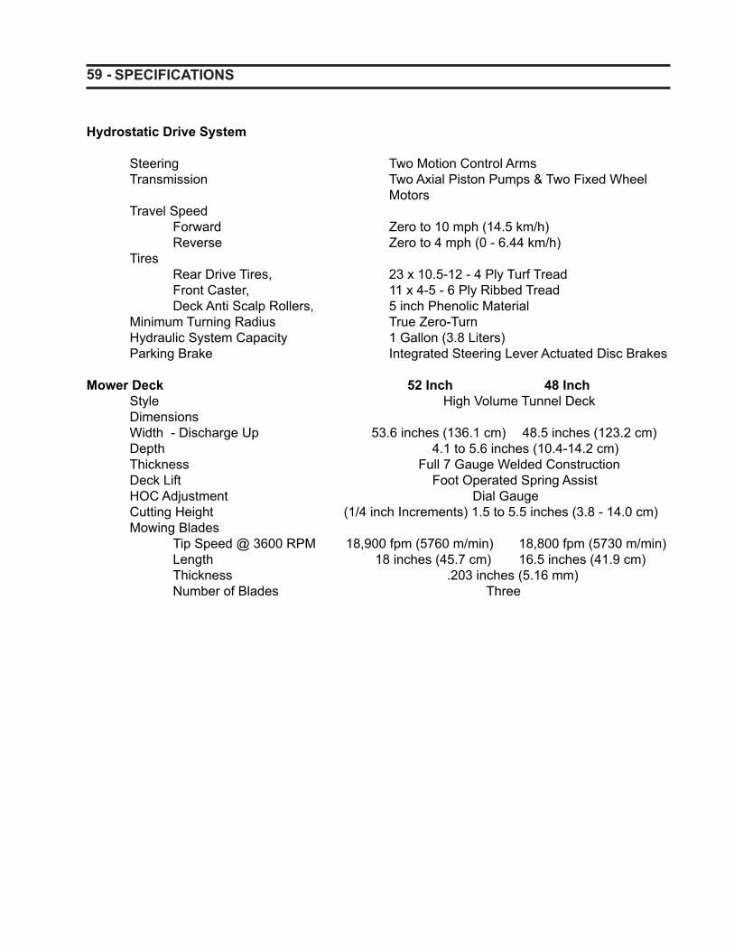
59 - SPECIFICATIONS
Hydrostatic Drive System
Steering Two Motion Control Arms Transmission Two Axial Piston Pumps & Two Fixed Wheel Motors Travel Speed Forward Zero to 10 mph (14.5 km/h) Reverse Zero to 4 mph (0 - 6.44 km/h) Tires Rear Drive Tires, 23 x 10.5-12 - 4 Ply Turf Tread Front Caster, 11 x 4-5 - 6 Ply Ribbed Tread Deck Anti Scalp Rollers, 5 inch Phenolic Material Minimum Turning Radius True Zero-Turn Hydraulic System Capacity 1 Gallon (3.8 Liters) Parking Brake Integrated Steering Lever Actuated Disc Brakes
Mower Deck 52 Inch 48 Inch Style High Volume Tunnel Deck Dimensions Width - Discharge Up 53.6 inches (136.1 cm) 48.5 inches (123.2 cm) Depth 4.1 to 5.6 inches (10.4-14.2 cm) Thickness Full 7 Gauge Welded Construction Deck Lift Foot Operated Spring Assist HOC Adjustment Dial Gauge Cutting Height (1/4 inch Increments) 1.5 to 5.5 inches (3.8 - 14.0 cm) Mowing Blades Tip Speed @ 3600 RPM 18,900 fpm (5760 m/min) 18,800 fpm (5730 m/min) Length 18 inches (45.7 cm) 16.5 inches (41.9 cm) Thickness .203 inches (5.16 mm) Number of Blades Three
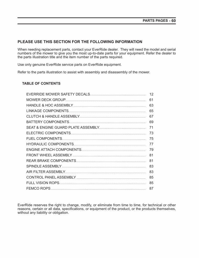
- 60
PLEASE USE THIS SECTION FOR THE FOLLOWING INFORMATION
When needing replacement parts, contact your EverRide dealer. They will need the model and serial numbers of the mower to give you the most up-to-date parts for your equipment. Refer the dealer to the parts illustration title and the item number of the parts required.
Use only genuine EverRide service parts on EverRide equipment.
Refer to the parts illustration to assist with assembly and disassembly of the mower.
TABLE OF CONTENTS
EVERRIDE MOWER SAFETY DECALS 12 MOWER DECK GROUP 61HANDLE & HOC ASSEMBLY 63LINKAGE COMPONENTS 65CLUTCH & HANDLE ASSEMBLY 67BATTERY COMPONENTS 69SEAT & ENGINE GUARD PLATE ASSEMBLY 71ELECTRIC COMPONENTS 73FUEL COMPONENTS 75HYDRAULIC COMPONENTS 77ENGINE ATTACH COMPONENTS 79FRONT WHEEL ASSEMBLY 81REAR BRAKE COMPONENTS 81SPINDLE ASSEMBLY 83 AIR FILTER ASSEMBLY 83CONTROL PANEL ASSEMBLY 85 FULL VISION ROPS 85FEMCO ROPS 87
EverRide reserves the right to change, modify, or eliminate from time to time, for technical or other reasons, certain or all data, specifi cations, or equipment of the product, or the products themselves, without any liability or obligation.
PARTS PAGES
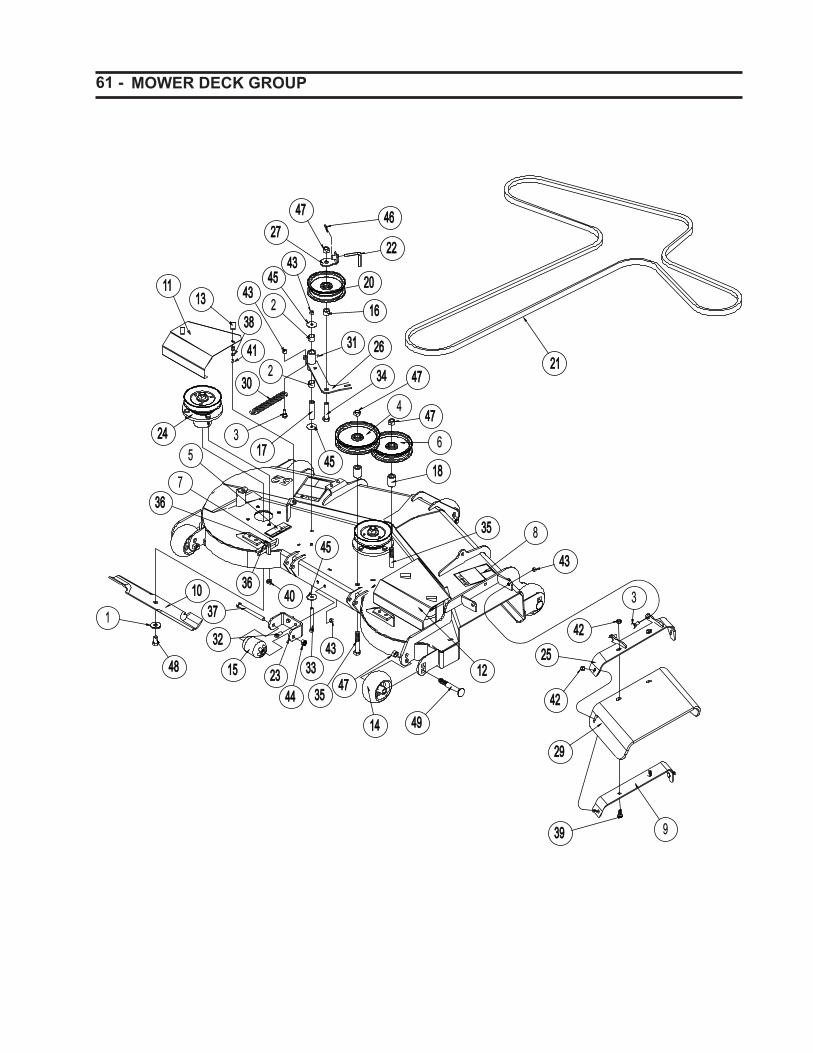
61 - MOWER DECK GROUP
4242
3131
2
4545
1818
4343
12122525
3
4949
3232
4848 2323
14040
4
4747
2424
2
4545
2626
47473535
37371010
2929
93939
4242
4343
4747
3434
4343
3030
2020
3636
73636
1717
1616
4747
4141
3838
4444
2727
13131111
2222
4646
3 6
15154343
1414
35354545
3333
5
8
2121

- 62 MOWER DECK GROUP
ITEM PART NO QTY DESCRIPTION
1 103906 3 WASHER, M14 X M40 X M4.5 FLAT Y2 105546 2 BRG, SLV .753 X .878 X .7503 135139 3 BOLT, 1/2 X 1.06 X 3/8-16 SLD 5 Y4 140280 1 PULLEY, FLAT 6.00 X .635 W/BRG5 160169 2 DECAL, WARNING - SHIELD6 161955 1 PULLEY, FLAT 5.50 X .635 W/BRG7 181194 1 U-BOLT, RD .63 X 4.50 X 3/8-16 SP Y8 181258 2 DECAL, DANGER - DECK9 191098 1 PLATE, DISCHG SHIELD SUPPORT
10 191108 3 BLADE, 18.000 LO-LIFT - 52" DECK191107 3 BLADE, 16.500 LO-LIFT - 48" DECK
11 191163 1 SHIELD, LH ZTM BELT12 191164 1 SHIELD, RH ZTM BELT13 191165 4 LATCH, 12-24 SOUTHCO14 191201 5 WHEEL, GAUGE Ø5.00 X 2.75 SYM15 191226 1 WHEEL, GAUGE Ø2.56 X 3.94 SYM16 191255 1 BUSHING, .688 X 1.13 X .62517 191347 1 TUBE, .750 X .438 X 3.04718 191355 2 BUSHING, .688 X 1.13 X 1.6819 191370 1 DECAL, DECK 52"
191369 1 DECAL, DECK 48"20 191374 1 PULLEY, FLAT 5.00 X .635 W/BRG21 191379 1 BELT, B144K SPECIAL - 52" DECK
191378 1 BELT, B138K SPECIAL - 48" DECK 22 191381 1 BELT KEEPER, 90° W/HOLE23 191486 1 BRACKET, ANTI-SCALP24 191500 3 ASSY, SPINDLE BALL BRG - 52" DECK
191517 3 ASSY, SPINDLE BALL BRG - 48" DECK25 191531 1 WLDT, DISCHARGE SHIELD BRACKET26 191533 1 WLDT, DECK BELT TENSIONER 48” - 52”
191579 1 WLDT, DECK BELT TENSIONER 52” PRIOR TO S/N 649410312
27 191537 1 WLDT, BELT KEEPER28 191611 1 WLDT, 52Z DECK S/O
191610 1 WLDT, 48Z DECK S/O 29 191559 1 SHIELD, RUBBER DISCHARGE30 356473 1 SPRING, EXT .910 X .177 X 6.15 Y31 959994 1 FTG, 1/4-28 TPR 45 GREASE ZERK32 960046 2 BOLT, 3/8-16 X 1.00 HEX 5 Y33 960058 1 BOLT, 3/8-16 X 4.00 HEX 5 Y34 960160 1 BOLT, 5/8-11 X 2.75 HEX 5 Y35 960163 2 BOLT, 5/8-11 X 3.50 HEX 5 Y36 960502 2 NUT, 3/8-16 STD HEX GR5 Y37 961343 1 BOLT, M12 X 1.75 X 130 HEX 8.8 Y38 961701 4 WASHER, M6 REG FLAT Y39 963020 4 BOLT, 3/8-16 X 1.00 CRG 5 Y40 964005 12 NUT, 7/16-20 HEX GR5 Y41 964014 4 LOCKNUT, 12-24 NYLOC Y42 964016 4 LOCKNUT, 3/8-16 WHIZ Y43 964022 6 LOCKNUT, 3/8-16 CROWN Y44 964044 1 LOCKNUT, M12 X 1.75 NYLOC Y45 964502 3 WASHER, .375 X 1.50 X .O63 FLAT Y
46 967356 1 RING, RUE .625 x .072 x 1.69047 967392 8 LOCKNUT, 5/8-11 CROWN Y48 967397 3 BOLT, 9/16-12 X 1.00 HEX 8 Y49 968088 5 BOLT, 5/8-11 X 4.50 CRG Y
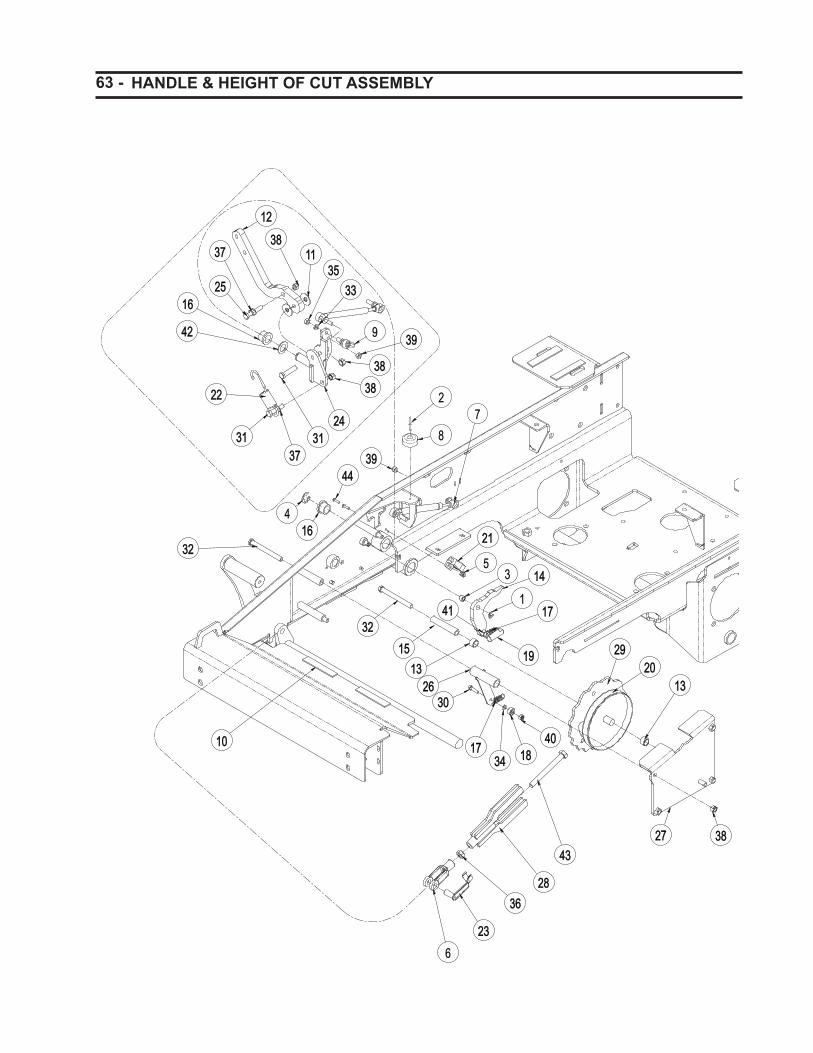
63 - HANDLE & HEIGHT OF CUT ASSEMBLY
1212
38381111
35353333
3838
9
3838
3939
31313737
2222
2525
3737
1616
31312424
2
8
39394444
41616
3232
6
2828
2323
1010
15151313
2121
53 1414
11717
1919
4141
30302626
404018183434
1717
2727 3838
1313
2929
7
2020
4343
3636
3232
4242

- 64 HANDLE & HEIGHT OF CUT ASSEMBLY
ITEM PART NO QTY DESCRIPTION
1 967358 2 E-RING, .375 X .035 2 968100 2 RIVET, 3/16 X .500 POP 3 103380 2 BEARING, SLV .377 X .503 X .3754 130886 2 E-RING, .750 X .050 5 130923 4 NUT, 10-24 KEPS 6 161897 1 YOKE, ADJUSTABLE 1/2-13 7 180231 2 DAMPENER, STEERING CONTROL8 180390 2 BUMPER, RUBBER .625 X 1.50 DIA9 180606 2 BALL JOINT, RH 5/16 FMAL W/STD
10 180897 6 FOAM, .125 X .750 X 4.0011 180961 4 WASHER, .400 X 1.27 X .062 NYLON12 191082 2 PLATE, STEERING CONTROL13 191298 2 BRG, SLV .627 X .752 X .500 BRNZ14 191137 2 PLATE, BRAKE LEVER15 191151 4 SPACER, .63 X .385 X 3.250 16 191179 4 BRG, FLG .750 X 1.00 X .750 BRNZ17 191183 3 SPRING, EXT .500 X .041 X 1.75 SS18 191185 1 BRG, BAL .250 X .688 X 31319 191186 2 BALL JOINT, 3/8X24 20 191208 1 DECAL, HOC INDEX21 191256 2 SWITCH, PLUNGER DP - N.O. - N.C.22 191261 2 SPRING, EXT .980 X .162 X 4.00 B23 191295 1 PIN, CVS SPG 1/2" YOKE SPEC 24 191510 1 WLDT, LH STEERING CONTROL
191513 1 WLDT, RH STEERING CONTROL25 967390 2 BOLT, 3/8-16 X 2.00 HEX 5 FLTD Y26 191527 1 WLDT, HOC INDEX ARM27 191528 1 WLDT, HOC COVER28 191532 1 WLDT, HOC LINK29 191617 1 WLDT, HOC CAM CONTROL S/O 30 960002 1 BOLT, 1/4-20 X 1.00 HEX 5 31 960049 4 BOLT, 3/8-16 X 1.75 HEX 5 32 960058 4 BOLT, 3/8-16 X 4.00 HEX 5 33 960601 2 WASHER, .313 MED SPRG LOCK 34 961701 1 WASHER, M6 REG FLAT 35 964003 2 NUT, 5/16-24 STD HEX GR5 36 964011 1 NUT, 1/2-13 JAM GR5 37 964016 4 LOCKNUT, 3/8-16 WHIZ 38 964022 10 LOCKNUT, 3/8-16 CROWN 39 964047 4 LOCKNUT, M8-1.25 CROWN 40 964048 1 LOCKNUT, 1/4-20 NYLOC 41 967054 2 NUT, 3/8-24 STD HEX GR5 42 967061 2 BUSHING, MACH .750 X 1.25 X .075 Y43 967189 1 BOLT, 1/2-13 X 4.50 HEX 8 44 967340 4 SCREW, 10-24 X .625 PAN PHL MAC
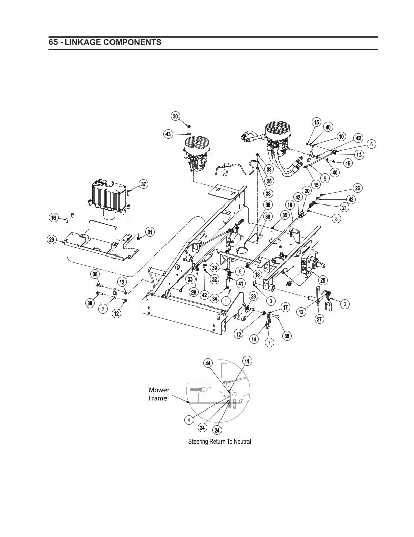
65 - LINKAGE COMPONENTS
3030
4343
15154040
10106
13131515
40409
1515
2626
2727
383871414
1212
313434
3939
4141
5
4242
3232
1616
2929
3737
3131
2222
42422121
8
20204242
1919
1818
1717 2
2828
1212
2323
3838
3333
2525
3333
4242
3636 3535
2323
12122
3838
38381212
Steering Return To Neutral
11114444
42424 2424

- 66 LINKAGE COMPONENTS
ITEM PART NO QTY DESCRIPTION
1 967393 2 BOLT, 1/4-20 X 2.75 SOC 8 2 150109 3 CHAIN - 3 LINKS 3 180922 2 E-RING, 1.00 X .050 4 180956 2 YOKE, 1/4-20 RH ADJUSTABLE 5 180957 2 SPRING, COM .784 X .092 X 1.506 180982 2 BALL JOINT, LH 5/16 FMAL W/STD7 181017 3 U-BOLT, RD 1.00 X 2.50 X 3/8-16 8 967353 2 RING, RUE .375 x .054 x 1.2549 191080 2 ROD, PUMP CONTROL HORNET
10 191081 2 PLATE, PUMP CONTROL ARM HORNET11 967350 2 RING, RUE .250 x .041 x .84412 967342 5 LOCKNUT, 7/16-14 WHIZ 13 967338 2 NUT, 5/16-24 HEX GR5 LH 14 964016 6 LOCKNUT, 3/8-16 WHIZ 15 964003 6 NUT, 5/16-24 STD HEX GR5 16 963074 4 BOLT, 5/16-18 X 1.00 CRG 2 17 191129 1 CHAIN, 2 LINKS 1/4" 18 967054 2 NUT, 3/8-24 STD HEX GR5 19 191175 2 ROD, BRAKE20 191176 2 PIN, BRAKE LINKAGE21 191177 2 SPRING, COM .710 X .142 X 2.5022 964066 2 LOCKNUT, 3/8-24 CROWN 23 964061 4 LOCKNUT, 7/16-14 CENTER 24 964048 4 LOCKNUT, 1/4-20 NYLOC 25 191227 1 CABLE, BATTERY - 35" GROUND26 191509 2 WLDT, WHEEL MOTOR PLATE27 191511 1 WLDT, LH FRONT DECK LIFT28 191512 1 WLDT, RH FRONT DECK LIFT29 191516 1 WLDT, BATTERY/TANK PLATE30 964025 4 LOCKNUT, 7/16-14 CROWN 31 964022 4 LOCKNUT, 3/8-16 CROWN 32 964021 7 LOCKNUT, 5/16-18 CROWN 33 964019 2 LOCKNUT, 5/16-18 WHIZ 34 473450 2 BOLT, 1/2-13X2 3/4 GR 2 Y35 960025 3 BOLT, 5/16-18 X 1.50 HEX 5 36 960026 1 BOLT, 5/16-18 X 1.75 HEX 5 37 960047 4 BOLT, 3/8-16 X 1.25 HEX 5 38 960081 9 BOLT, 7/16-14 X 1.50 HEX 5 39 960504 2 NUT, 1/2-13 STD HEX GR5 40 960601 4 WASHER, .313 MED SPRG LOCK 41 960700 2 WASHER, .250 REG FLAT 42 960701 10 WASHER, .313 REG FLAT 43 960702 4 WASHER, .375 REG FLAT 44 962200 2 PIN, CVS .250 X 1.00 X .859
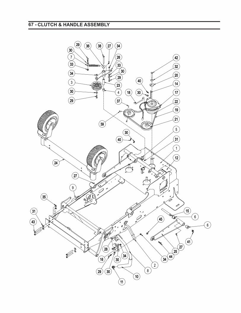
67 - CLUTCH & HANDLE ASSEMBLY
3333
3434
3030
3
2929
383836362929
7
3434
2626
3333
4242
3232
2020
14144040
3030
3737
3939
15156
6
41412727
2525
29292
1616
2828
81010
1111
3131
4343
3535
2727
24241212
1818
30303434
4040
3030
2929
2323
4
2121
1919
2222
1717
9
1
3434
3030
2727
3131
5
4444
4545
3030
3030

- 68 CLUTCH & HANDLE ASSEMBLY
ITEM PART NO QTY DESCRIPTION
1 191612 1 WLDT, FRAME AND DECK LIFT2 191082 2 PLATE, STEERING CONTROL3 103096 1 PULLEY, FLAT 4.00 X .670 W/BRG4 105546 2 BRG, SLV .753 X .878 X .7505 111910 2 CABLE TIE, .15 X 8.506 150079 4 BRG, FLG .750 X 1.13 X 1.007 110580 1 SPRING, EXT .875 X .125 X 4.25 8 181348 1 WLDT, LH STEERING HANDLE9 181347 1 WLDT, RH STEERING HANDLE
10 180617 2 GRIP, FOAM11 180639 2 PLUG, 7/8" END12 180779 1 DECAL, BELT ROUTING - PUMPS13 180954 2 DECAL, 9" EVERRIDE LOGO SM14 180962 1 KEY, .250 X .250 X 4.62 SQ - KAWASAKI
191196 1 KEY, .250 X .250 X 4.50 SQ - BRIGGS ENGINE15 191048 2 PIN, MFG .625X5.38X4.88 XDRL Y16 191083 2 PLATE, STEERING CONTROL BENT17 191109 1 CLUTCH, ELECT - OGURA, GT2.518 191166 1 ROD, CLUTCH ANTIROTATION19 191199 1 BELT, A46K ARAMID CORD20 191203 1 WASHER, CLUTCH UNIVERSAL W/KEY21 191265 2 PULLEY, V-BELT 5.00 X .591 W/KEY22 191268 1 PULLEY, V-BELT 4.50 X 1.00 W/KEY23 191347 1 TUBE, Ø.750 X Ø.438 X 3.04724 191576 1 ASSY, FRONT AXLE 25 191577 2 WLDT, DECK PUSH LINK26 191581 1 WLDT, PUMP BELT TENSIONER27 959995 7 FTG, 1/4-28 STRGT GREASE ZERK28 960047 4 BOLT, 3/8-16 X 1.25 HEX 5 29 960048 7 BOLT, 3/8-16 X 1.50 HEX 5 30 960701 11 WASHER, .313 REG FLAT 31 960702 5 WASHER, .375 REG FLAT 32 960703 1 WASHER, .438 REG FLAT 33 964016 2 LOCKNUT, 3/8-16 WHIZ 34 964022 12 LOCKNUT, 3/8-16 CROWN 35 964025 4 LOCKNUT, 7/16-14 CROWN 36 964502 1 WASHER, .375 X 1.50 X .O63 FLAT 37 966058 2 KEY, M5 X M5 X M30 RD38 960058 1 BOLT, 3/8-16 X 4.00 HEX 5 39 967343 4 SET SCREW, 5/16-18 X .625 SQ CUP40 967353 2 RING, RUE .375 x .054 x 1.25441 967357 2 RING, RUE .750 x .080 x 2.08142 967394 1 BOLT, 7/16-20 X 2.75 HEX 5 43 967399 4 BOLT, 7/16-14 X 3.5 HEX 8 44 960117 2 BOLT, 1/2-13 X 2.25 HEX 545 964000 2 LOCKNUT, 1/2-13 CROWN
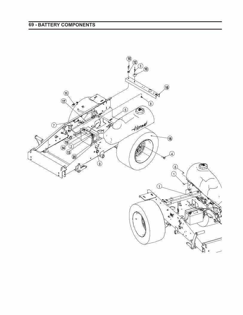
69 - BATTERY COMPONENTS
1111
4
1515
31010
1212
8
7
21313
9
1717
19191818
1616
1414
5
2020
1
6
1

- 70 BATTERY COMPONENTS
ITEM PART NO QTY DESCRIPTION
1 967340 11 SCREW, 10-24 X .625 PAN PHL MAC 2 967152 2 BOLT, 5/16-18 X .750 CRG 5 3 968100 2 RIVET, 3/16 X .500 POP 4 967133 10 BOLT, 1/2-20 X 1.00 LUG 5 111910 9 CABLE TIE, .15 X 8.506 130923 5 NUT, 10-24 KEPS 7 130924 3 CLAMP, 1/2 SPRING HOSE8 964022 2 LOCKNUT, 3/8-16 CROWN 9 960501 2 NUT, 5/16-18 STD HEX GR5
10 180390 2 BUMPER, RUBBER .625 X 1.50 DIA11 191200 1 HARNESS, POWER UNIT WIRE12 960702 4 WASHER, .375 REG FLAT 13 960601 2 WASHER, .313 MED SPRG LOCK 14 180996 1 DECAL, DANGER - BATTERY 15 960046 2 BOLT, 3/8-16 X 1.00 HEX 5 16 191289 1 PLATE, TOP CROSSMEMBER17 191282 1 ASSY, HORNET FUEL LINE18 191228 2 ASSY, TIRE & RIM - 23X10.50-1219 181228 1 BAND, 15'' RUBBER BUNGEE20 191216 1 CABLE, BATTERY - 35" POSITIVE
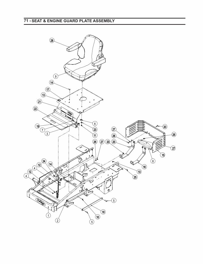
71 - SEAT & ENGINE GUARD PLATE ASSEMBLY
1515
2727
2020
5
18181010
1919
1010
2626 2727
1111 2626
20202727
2626
2020
8
1616
2525
2
2222
2121
1717
5
1313
2323
6
1414
73
9
12124
12124
2424
1
1414
2828

- 72 SEAT & ENGINE GUARD PLATE ASSEMBLY
ITEM PART NO QTY DESCRIPTION
1 191612 1 WLDT, FRAME AND DECK LIFT2 967354 4 RING, RUE .500 x .062 x 1.420
3 967398 1 WASHER, .510 X 1.00 X .068 NYLON4 964048 2 LOCKNUT, 1/4-20 NYLOC 5 110330 4 PIN, CVS .500 X 1.25 X 1.02 Y6 111886 1 P-CLIP, .500 INSULATED7 135139 1 BOLT, 1/2 X 1.00 X 3/8-16 SLD 5 8 180604 1 PLATE, HITCH9 180916 1 SEAT, FULL SUSPENSION
10 964022 5 LOCKNUT, 3/8-16 CROWN 11 964021 4 LOCKNUT, 5/16-18 CROWN 12 960700 2 WASHER, .250 REG FLAT 13 181003 2 DECAL, PARK BRAKE14 963095 2 BOLT, 1/4-20 X .750 CRG 5 15 191615 1 PLATE, REAR ENG. GUARD S/O W/DECALS
16 191074 2 BRACE, BENT ARM HITCH17 191614 1 PLATE, SEAT S/O W/DECALS18 191142 4 PLATE, ARM CONNECTOR LINK19 191613 1 PLATE, FLOOR PAN X/O W/DECALS20 963019 12 BOLT, 3/8-16 X 1.00 CRG 5 SN 21 191214 1 DECAL, SAFETY GROUP22 191257 4 TAPE, TRACTION 3.00 X 17.0023 960701 4 WASHER, .313 REG FLAT 24 191487 1 CHAIN, .148 X 28 LINKS25 960046 4 BOLT, 3/8-16 X 1.00 HEX 5 26 960502 12 NUT, 3/8-16 STD HEX GR5 27 960602 12 WASHER, .375 MED SPRG LOCK 28 181380 2 ARM REST
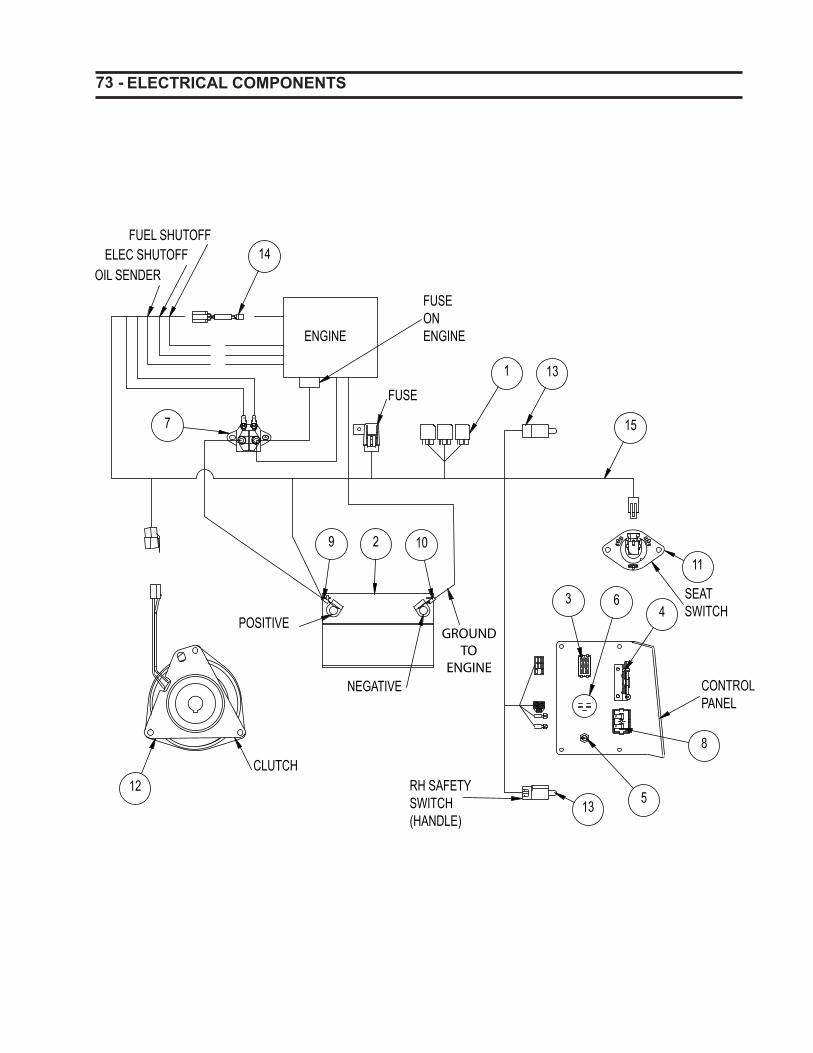
73 - ELECTRICAL COMPONENTS
ENGINE
FUSEONENGINE
POSITIVE
NEGATIVE
SEATSWITCH
CONTROLPANEL
RH SAFETYSWITCH(HANDLE)
CLUTCH
FUSE
14
13
29 10
1312
3 6
8
5
4
1
7
FUEL SHUTOFFELEC SHUTOFF
OIL SENDER
15
11

- 74 ELECTRIC COMPONENTS
ITEM PART NO QTY DESCRIPTION
1 102770 3 RELAY, ISO MINI ELEC.2 N/A 1 BATTERY, 12V - SEALED3 136574 1 SWITCH, PTO ENGAGEMENT4 180272 1 CABLE, THROTTLE
5 180273 1 CABLE, CHOKE 48”6 180620 1 SWITCH, KEY - 3 POSITION7 180640 1 SOLENOID, 12 V STARTER8 180799 1 METER, QUARTZ HOUR9 180842 1 CABLE, 12” STARTER10 191227 1 CABLE, BATTERY - 35” GROUND11 181074 1 SEAT SWITCH S/O12 191109 1 CLUTCH, ELECT - OGURA, GT2.513 191256 2 SWITCH, PLUNGER DP - N.O. - N.C.14 191258 1 ADAPTER HARNESS, KAWASAKI
191358 1 ADAPTER HARNESS, BRIGGS15 191200 1 HARNESS, WIRING
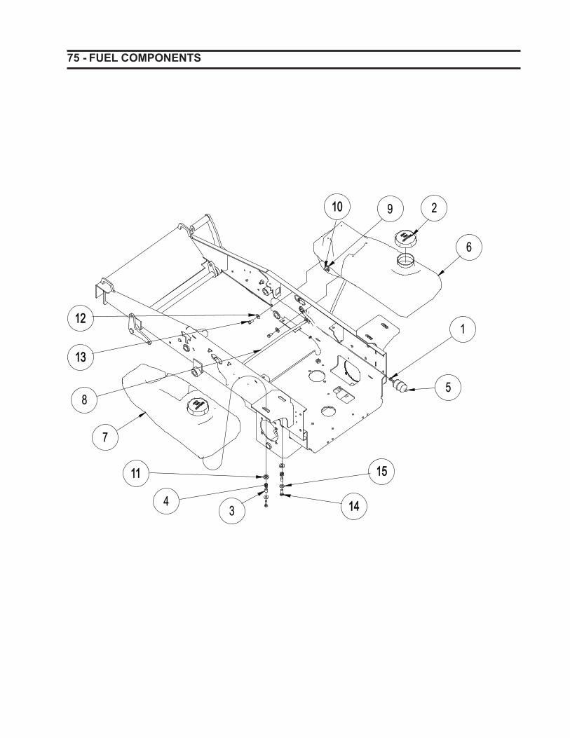
75 - FUEL COMPONENTS
2
6
5
1
1414
1515
34
7
1313
1212
8
1111
91010

- 76 FUEL COMPONENTS
ITEM PART NO QTY DESCRIPTION
1 130924 3 CLAMP, 1/2 SPRING HOSE 2 181251 2 CAP, FUEL 3 181023 4 SPACER, GAS TANK ATTACHMENT 4 181027 4 SPRING, COM .660 X .067 X .625 5 181060 1 FUEL FILTER - S/O 6 191194 1 FUEL TANK, RH W/GRAPHICS 7 191195 1 FUEL TANK, LH W/GRAPHICS 8 191282 1 ASSY, HORNET FUEL LINE W/CHECK VALVE 9 181208 2 GROMMET, TANK FITTING RUBBER 10 191605 2 FITTING. 90 DEGREE 11 964505 4 WASHER, .500 X 1.00 X .105 FLAT 12 960702 4 WASHER, .375 REG FLAT 13 960045 4 BOLT, 3/8-16 X .750 HEX 5 14 960047 4 BOLT, 3/8-16 X 1.25 HEX 5 15 960701 4 WASHER, .313 REG FLAT
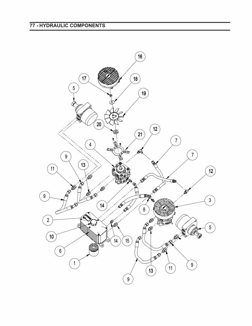
77 - HYDRAULIC COMPONENTS
5
1212
7
7
1212
4
3
5
911
91313
6
2
9
11
91313
1414
1
1010
8
14 15
1717
1616
2121
1818
2020
1919

- 78 HYDRAULIC COMPONENTS
ITEM PART NO QTY DESCRIPTION
1 180909 1 FILTER, 25 MICRON 2 181254 1 DECAL, HYDRAULIC OIL 3 191101 1 PUMP, HYDRO-GEAR LEFT HAND 4 191102 1 PUMP, HYDRO-GEAR RIGHT HAND N/I 191618 2 SEAL KIT, HYDRO-GEAR PUMP 5 191103 2 WHEEL MOTOR, PARKER TL195 N/I 191619 2 SEAL KIT, PARKER WHEEL MOTOR 6 191616 1 TANK, HYDRAULIC S/O W/DECALS 7 191204 2 HOSE, HYD 3/8 9/16&3/4FJICSW 8 191205 2 HOSE, HYD 3/8 9/16JICFESW 9 191206 4 HOSE, HYD 1/2 3/4FJICSW45° 10 191600 1 CAP, HYDRAULIC 11 231104 4 ADAPTER, 7/8MOR X 3/4MJIC 12 313270 4 FTG, 90 9/16 MOR X 9/16 MJIC 13 313391 4 ADAPTER, 3/4-16MORX 3/4-16JIC 14 221285 2 FTG, ADP 9/16-18MORX9/16MJIC 15 313391 2 ADAPTER, 3/4-16MORX 3/4-16JIC 16 191620 2 SHROUD, HORNET PUMP 17 964066 2 LOCKNUT, 3/8-24 CROWN 18 180995 2 WASHER, .375 X 1.24 X .072 BLVL 19 191621 2 FAN, HORNET PUMP 20 180994 2 HUB, FAN 21 191622 2 PLATE, SHROUD MOUNT
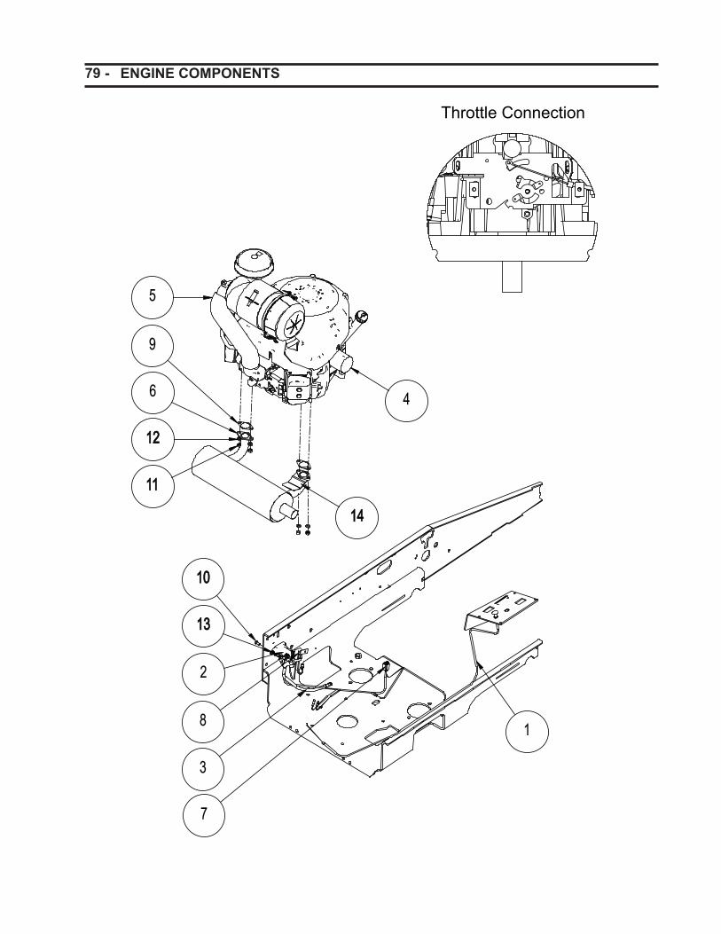
79 - ENGINE COMPONENTS
9
6
1212
1111
5
2
8
3
1
4
1010
1313
7
Throttle Connection
1414

- 80 ENGINE COMPONENTS
ITEM PART NO QTY DESCRIPTION
1 180273 1 CABLE, CHOKE 48"2 180640 1 SOLENOID, 12 V STARTER3 180842 1 CABLE, 12" STARTER4 181073 1 OIL FILTER - KAWASAKI
191631 1 OIL FILTER - BRIGGS & STRATTON5 191119 1 ENGINE, KAWASAKI 19 HP
191123 1 ENGINE, KAWASAKI 23 HP 191359 1 ENGINE, BRIGGS & STRATTON 25
6 191125 1 MUFFLER, KAWASAKI ONLY FH-HORI 7 191258 1 ADAPTER HARNESS, KAWASAKI
8 191260 1 ADAPTER, HARNESS KAWASAKI, FUSE191358 1 ADAPTER, BRIGGS WIRE HARNESS
9 191601 2 KIT, MUFFLER GASKET *10 960000 2 BOLT, 1/4-20 X .500 HEX 5 11 N/A 2 NUT, M8 X 1.25 HEX GR8.8 12 N/A 2 WASHER, M8 SPRG LOCK 13 964040 2 LOCKNUT, 1/4-20 WHIZ 14 191365 1 SHIELD, EXHAUST
* Includes items 9, 11, & 12.
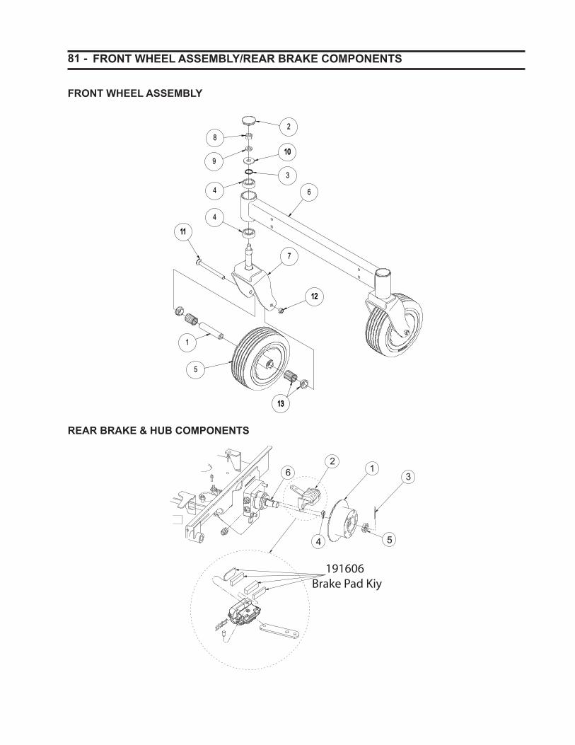
81 - FRONT WHEEL ASSEMBLY/REAR BRAKE COMPONENTS
28
1010
3
4 6
1111
7
1212
5
1
9
4
1313
FRONT WHEEL ASSEMBLY
REAR BRAKE & HUB COMPONENTS
16 3
4 5
2
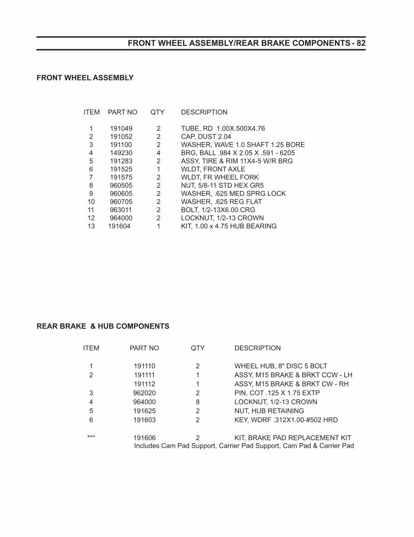
- 82 FRONT WHEEL ASSEMBLY/REAR BRAKE COMPONENTS
ITEM PART NO QTY DESCRIPTION
1 191049 2 TUBE, RD 1.00X.500X4.76 2 191052 2 CAP, DUST 2.04 3 191100 2 WASHER, WAVE 1.0 SHAFT 1.25 BORE 4 149230 4 BRG, BALL .984 X 2.05 X .591 - 6205 5 191283 2 ASSY, TIRE & RIM 11X4-5 W/R BRG 6 191525 1 WLDT, FRONT AXLE 7 191575 2 WLDT, FR WHEEL FORK 8 960505 2 NUT, 5/8-11 STD HEX GR5 9 960605 2 WASHER, .625 MED SPRG LOCK 10 960705 2 WASHER, .625 REG FLAT 11 963011 2 BOLT, 1/2-13X6.00 CRG 12 964000 2 LOCKNUT, 1/2-13 CROWN 13 191604 1 KIT, 1.00 x 4.75 HUB BEARING
FRONT WHEEL ASSEMBLY
REAR BRAKE & HUB COMPONENTS
ITEM PART NO QTY DESCRIPTION
1 191110 2 WHEEL HUB, 8" DISC 5 BOLT2 191111 1 ASSY, M15 BRAKE & BRKT CCW - LH
191112 1 ASSY, M15 BRAKE & BRKT CW - RH 3 962020 2 PIN, COT .125 X 1.75 EXTP 4 964000 8 LOCKNUT, 1/2-13 CROWN 5 191625 2 NUT, HUB RETAINING 6 191603 2 KEY, WDRF .312X1.00-#502 HRD
*** 191606 2 KIT, BRAKE PAD REPLACEMENT KITIncludes Cam Pad Support, Carrier Pad Support, Cam Pad & Carrier Pad
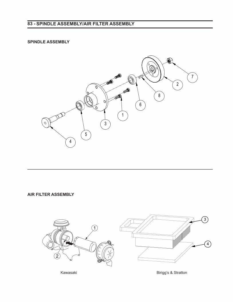
83 - SPINDLE ASSEMBLY/AIR FILTER ASSEMBLY
45
3
1
6
8
27
AIR FILTER ASSEMBLY
1
2
SPINDLE ASSEMBLY
Kawasaki Birigg’s & Stratton
3
4

- 84 SPINDLE ASSEMBLY/AIR FILTER ASSEMBLY
ITEM PART NO QTY DESCRIPTION
1 145561 4 BOLT, 7/16-20 X 1.22 SPC 52 180780 1 PULLEY, V-BELT 5.75X.750 52”
191115 1 PULLEY, V-BELT 4.50X.750 48”3 191013 1 SPINDLE, MACHINED BALL BRG4 191014 1 SHAFT, SPINDLE
5 149230 1 BRG, BALL M25XM52XM15 62056 103977 1 BRG, BALL M20XM52XM15 63047 964024 1 LOCKNUT, 3/4-16 CROWN 8 966045 1 KEY, .250 X .250 X 1.00 SQ
AIR FILTER ASSEMBLY
ITEM PART NO QTY DESCRIPTION 1 181071 1 FILTER, PRIMARY AIR 2 181072 1 FILTER, SECONDARY AIR 3 191630 1 FILTER, BRIGGS PREMIUM AIR 4 191632 1 FILTER, BRIGGS ENGINE PRE-CLEANER
* NOTE: Quantities listed are per spindle.
SPINDLE ASSEMBLY
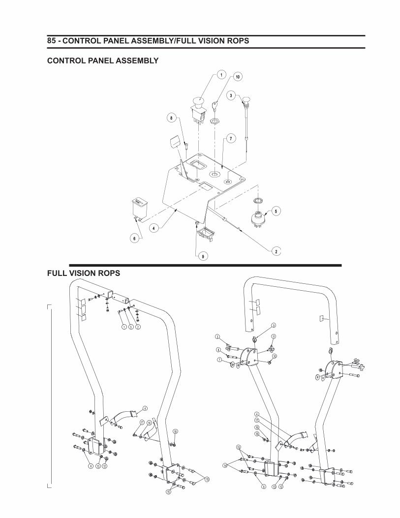
85 -
33
55
77
11
22
44
99
66
88
1010
CONTROL PANEL ASSEMBLY/FULL VISION ROPS
CONTROL PANEL ASSEMBLY
FULL VISION ROPS
6 13 12
15
1617
4
18
1 5 2
1513
14
6
15
18
17
16
4
12
10
11
9
7
8
3
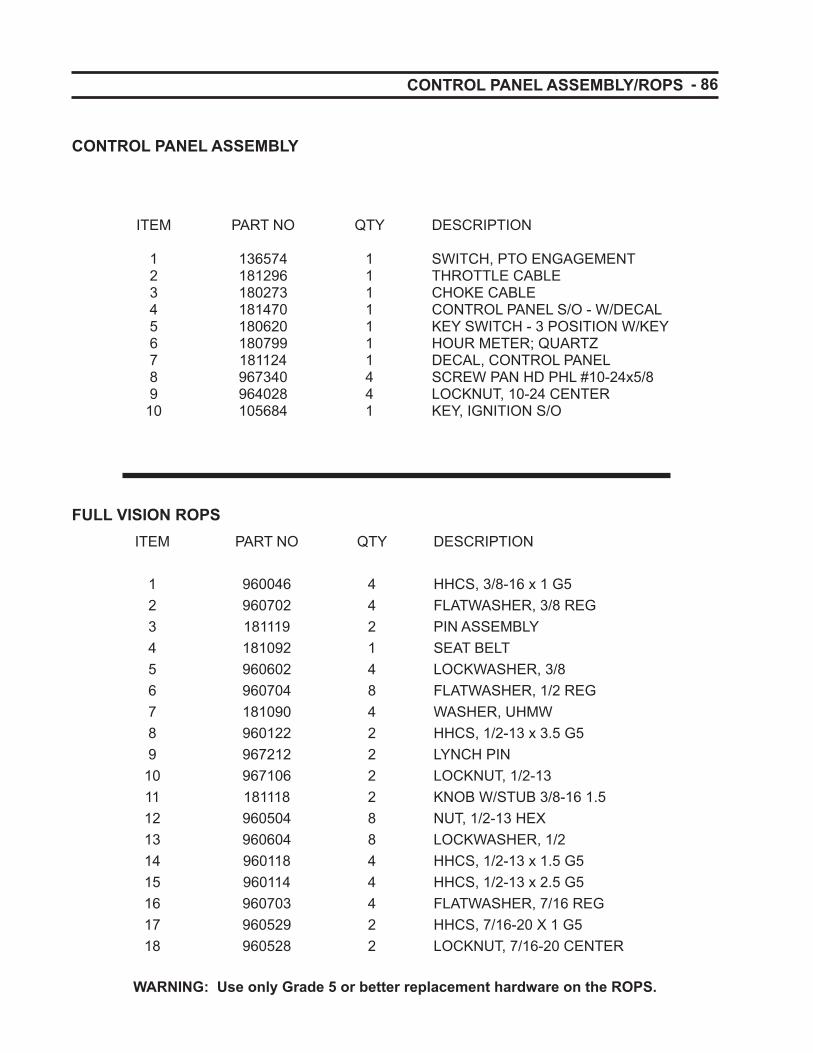
- 86 CONTROL PANEL ASSEMBLY/ROPS
ITEM PART NO QTY DESCRIPTION
1 136574 1 SWITCH, PTO ENGAGEMENT 2 181296 1 THROTTLE CABLE 3 180273 1 CHOKE CABLE 4 181470 1 CONTROL PANEL S/O - W/DECAL 5 180620 1 KEY SWITCH - 3 POSITION W/KEY 6 180799 1 HOUR METER; QUARTZ 7 181124 1 DECAL, CONTROL PANEL 8 967340 4 SCREW PAN HD PHL #10-24x5/8 9 964028 4 LOCKNUT, 10-24 CENTER 10 105684 1 KEY, IGNITION S/O
CONTROL PANEL ASSEMBLY
FULL VISION ROPSITEM PART NO QTY DESCRIPTION
1 960046 4 HHCS, 3/8-16 x 1 G52 960702 4 FLATWASHER, 3/8 REG3 181119 2 PIN ASSEMBLY4 181092 1 SEAT BELT5 960602 4 LOCKWASHER, 3/86 960704 8 FLATWASHER, 1/2 REG7 181090 4 WASHER, UHMW8 960122 2 HHCS, 1/2-13 x 3.5 G59 967212 2 LYNCH PIN
10 967106 2 LOCKNUT, 1/2-1311 181118 2 KNOB W/STUB 3/8-16 1.512 960504 8 NUT, 1/2-13 HEX13 960604 8 LOCKWASHER, 1/214 960118 4 HHCS, 1/2-13 x 1.5 G515 960114 4 HHCS, 1/2-13 x 2.5 G516 960703 4 FLATWASHER, 7/16 REG17 960529 2 HHCS, 7/16-20 X 1 G5
18 960528 2 LOCKNUT, 7/16-20 CENTER
WARNING: Use only Grade 5 or better replacement hardware on the ROPS.
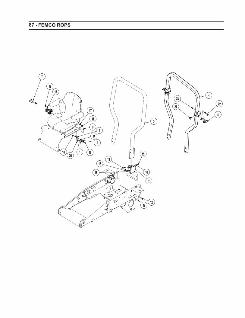
87 -
12121212
2
1616
15151313
1515
1616
7
19191717
1717
1111
1010
61414
18181
5
9
2020
3
4
8
22222323
2121
FEMCO ROPS

- 88
ITEM PART NO QTY DESCRIPTION
1 160176 1 SPRING, COMPRESSION2 181561 2 WLDT, ROPS MOUNT3 191491 1 ROPS, FIXED4 191492 1 ROPS, FOLDING5 191495 1 HOOK, LATCH
6 191496 1 BRACKET, LATCH7 181572 1 ASSY, SEAT BELT8 181591 2 ASSY, FOLDING ROPS LOCK PIN S/O9 963074 2 BOLT, 5/16-18 X 1.00 CRG GR5 Y10 960047 1 BOLT, 3/8-16 X 1.25 HEX GR5 Y11 960079 2 BOLT, 7/16-14 X 1.00 HEX GR5 Y12 960114 8 BOLT, 1/2-13 X 1.50 HEX GR5 Y13 960122 4 BOLT, 1/2-13 X 3.50 HEX 5 Y14 960502 1 NUT, 3/8-16 STD HEX GR5 Y15 960504 12 NUT, 1/2-13 STD HEX GR5 Y16 960604 12 WASHER, .500 MED SPRG LOCK Y17 960703 4 WASHER, .438 REG FLAT Y18 964022 1 LOCKNUT, 3/8-16 CROWN Y 19 964025 2 LOCKNUT, 7/16-14 CROWN Y 20 964019 2 LOCKNUT, 5/16-18 WHIZ Y21 181592 2 KNOB, 5/16-18 ROUND S/O22 960121 2 BOLT, 1/2-13 X 3.50 HEX 5 Y23 967106 2 LOCKNUT, 1/2-13 CENTER
FEMCO ROPS
WARNING: Use only Grade 5 or better replacement hardware on the ROPS.

89 - PARTS LIST
PART NO PAGE ITEM PART NO PAGE ITEM
102770 74 1103096 68 3103380 64 3103906 62 1103977 84 6105546 62 2105546 68 4105684 86 10110330 72 5110580 68 7111886 72 6111910 68 5111910 70 5130886 64 4130923 64 5130923 70 6130924 70 7130924 76 1135139 62 3135139 72 7136574 74 3136574 86 1140280 62 4145561 84 1149230 82 4149230 84 5150079 68 6150109 66 2160169 62 5160176 88 1161897 64 6161955 62 6180231 64 7180272 74 4180273 74 5180273 80 1180273 86 3180390 64 8180390 70 10
180604 72 8180606 64 9180617 68 10180620 74 6180620 86 5180639 68 11180640 74 7180640 80 2180779 68 12180780 84 2180799 74 8180799 86 6180842 74 9180842 80 3180897 64 10180909 78 1180916 72 9180922 66 3180954 68 13180956 66 4180957 66 5180961 64 11180962 68 14180982 66 6180994 78 20180995 78 18180996 70 14181003 72 13181017 66 7181023 76 3181027 76 4181060 76 5181071 84 1181072 84 2181073 80 4181074 74 11181090 86 7181092 86 4181118 86 11

- 90 PARTS LIST
PART NO PAGE ITEM PART NO PAGE ITEM
181119 86 3181124 86 7181194 62 7181208 76 9181228 70 19181251 76 2181254 78 2181258 62 8181296 86 2181347 68 9181348 68 8181380 72 28181470 86 4181561 88 2181572 88 7181591 88 8181592 88 21191013 84 3191014 84 4191048 68 15191049 82 1191052 82 2191074 72 16191080 66 9191081 66 10191082 64 12191082 68 2191083 68 16191098 62 9191100 82 3191101 78 3191102 78 4191103 78 5191107 62 10191108 62 10191109 68 17191109 74 12191110 82 1191111 82 2
191112 82191115 84191119 80 5191123 80 5191125 80 6191129 66 17191137 64 14191142 72 18191151 64 15191163 62 11191164 62 12191165 62 13191166 68 18191175 66 19191176 66 20191177 66 21191179 64 16191183 64 17191185 64 18191186 64 19191194 76 6191195 76 7191196 68 14191199 68 19191200 70 11191200 74 15191201 62 14191203 68 20191204 78 7191205 78 8191206 78 9191208 64 20191214 72 21191216 70 20191226 62 15191227 66 25191227 74 10191228 70 18191255 62 16

91 - PARTS LIST
PART NO PAGE ITEM PART NO PAGE ITEM
191256 64 21191256 74 13191257 72 22191258 74 14191258 80 7191260 80 8191261 64 22191265 68 21191268 68 22191282 70 17191282 76 8191283 82 5191289 70 16191295 64 23191298 64 13191347 62 17191347 68 23191355 62 18191358 74 14191358 80 8191359 80 5191365 80 14191369 62 19191370 62 19191374 62 20191378 62 21191379 62 21191381 62 22191486 62 23191487 72 24191491 88 3191492 88 4191495 88 5191496 88 6191500 62 24191509 66 26191510 64 24191511 66 27191512 66 28
191513 64 24191516 66 29191517 62 24191525 82 6191527 64 26191528 64 27191531 62 25191532 64 28191533 62 26191537 62 27191559 62 29191575 82 7191576 68 24191577 68 25191579 62 26191581 68 26191600 78 10191601 80 9191603 82 6191604 82 13191605 76 10191606 82 ***191610 62 28191611 62 28191612 68 1191612 72 1191613 72 19191614 72 17191615 72 15191616 78 6191617 64 29191618 78 N/I191619 78 N/I191620 78 16191621 78 19191622 78 21191625 82 5191630 84 3191631 80 4

- 92
PART NO PAGE ITEM
PARTS LIST
PART NO PAGE ITEM
191632 84 4221285 78 14231104 78 11313270 78 12313391 78 13313391 78 15356473 62 30473450 66 34959994 62 31959995 68 27960000 80 10960002 64 30960025 66 35960026 66 36960045 76 13960046 62 32960046 70 15960046 72 25960046 86 1960047 66 37960047 68 28960047 76 14960047 88 10960048 68 29960049 64 31960058 62 33960058 64 32960058 68 38960079 88 11960081 66 38960114 86 15960114 88 12960117 68 44960118 86 14960121 88 22960122 86 8960122 88 13960160 62 34960163 62 35
960501 70 9960502 62 36960502 72 26960502 88 14960504 66 39960504 86 12960504 88 15960505 82 8960528 86 18960529 86 17960601 64 33960601 66 40960601 70 13960602 72 27960602 86 5960604 86 13960604 88 16960605 82 9960700 66 41960700 72 12960701 66 42960701 68 30960701 72 23960701 76 15960702 66 43960702 68 31960702 70 12960702 76 12960702 86 2960703 68 32960703 86 16960703 88 17960704 86 6960705 82 10961343 62 37961701 62 38961701 64 34962020 82 3962200 66 44

93 - PARTS LIST
PART NO PAGE ITEM PART NO PAGE ITEM
963011 82 11963019 72 20963020 62 39963074 66 16963074 88 9963095 72 14964000 68 45964000 82 12964000 82 4964003 64 35964003 66 15964005 62 40964011 64 36964014 62 41964016 62 42964016 64 37964016 66 14964016 68 33964019 66 33964019 88 20964021 66 32964021 72 11964022 62 43964022 64 38964022 66 31964022 68 34964022 70 8964022 72 10964022 88 18964024 84 7964025 66 30964025 68 35964025 88 19964028 86 9964040 80 13964044 62 44964047 64 39964048 64 40964048 66 24
964048 72 4964061 66 23964066 66 22964066 78 17964502 62 45964502 68 36964505 76 11966045 84 8966058 68 37967054 64 41967054 66 18967061 64 42967106 86 10967106 88 23967133 70 4967152 70 2967189 64 43967212 86 9967338 66 13967340 64 44967340 70 1967340 86 8967342 66 12967343 68 39967350 66 11967353 66 8967353 68 40967354 72 2967356 62 46967357 68 41967358 64 1967390 64 25967392 62 47967393 66 1967394 68 42967397 62 48967398 72 3967399 68 43968088 62 49

- 94 NOTES

95 -
Oil Filter and
Engine Oil Change Lubricate Machine
Air Cleaner Element
Clean or Replace
Record dates of the services as they are performed for easy reference.
MAINTENANCE RECORDS
1912101/16/06


![Migration d'un projet Hornet 2.0 vers Hornet 3 · Communauté Adullact - [ HORNET ] Migration d'un projet Hornet 2.0 vers Hornet 3.1 Développement Hornet HORNET_GUI_Migration d'un](https://img.pdfslide.net/doc/110x75/5f2456cb7890f4440e0171ec/migration-dun-projet-hornet-20-vers-hornet-3-communaut-adullact-hornet-.jpg)