Embed Size (px)
Citation preview
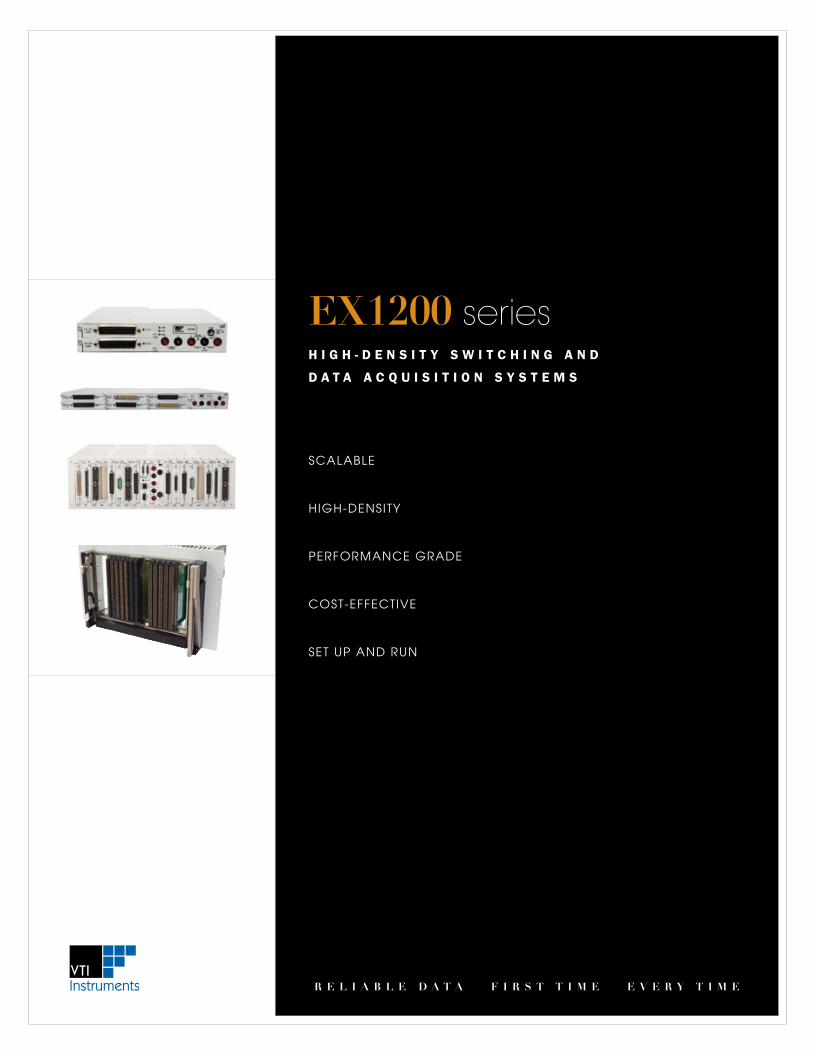
Scalable
HIGH-DeNSITY
PeRFORMaNce GRaDe
cOST-eFFecTIVe
SeT UP aND RUN
EX1200 seriesH i g H - D e n s i t y s w i t c H i n g a n D
D a t a a c q u i s i t i o n s y s t e m s
r E l i a b l E d a t a f i r s t t i m E E v E r y t i m E
eX1200 SeRIeS eX1200 SeRIeS
r e l i a b l e d a t a f i r s t t i m e e v e r y t i m e r e l i a b l e d a t a f i r s t t i m e e v e r y t i m e
2 3
OVERVIEW
Competitors pC-Based 2 a matrix ex1200-4003 2 a matrix
vs160 mm
dual 4 x 8; 64 two-wire crosspoints25 mHz bandwidth
285 mm
100
mm
dual 4 x 16; 128 two-wire crosspoints45 mHz bandwidth
100
mm
S w I T c H / M e a S U R e a N D c O N T R O l F O R D a T a a c q U I S I T I O N
when installed with the optional 6.5 digit DMM, the eX1200 family can be configured as a cost-effective, high-density, scanning
measurement and control instrument capable of acquiring data from thermocouples, RTDs, thermistors, and voltage/current
sensors at rates up to 1000 channels per second. Plug-in switch/multiplexer and digital input modules are used to expand
the number of channels that can be scanned in a single system. additional plug-in modules extend the capabilities of this
instrument for data acquisition by adding precision analog and digital outputs for controlling external devices. a powerful
on-board graphical interface provides quick and easy setup for test sequences and storing data to disk. The eX1200 is also
supported by eXlab to provide even more capability, including customized data display and limit checking/alarms.
H I G H - D e N S I T Y S w I T c H I N G a N D
I / O I N S T R U M e N T
The eX1200 series is the highest density switch and I/O
instrument on the market today with the capacity to house
up to 576 channels of multiplexing and the ability to mix
low-level, power, and RF switch modules in a single 1U
mainframe. This scalable family of products is designed to
leverage capital investments in one common hardware
and software platform that can be used in development,
manufacturing, and field service with 3U mainframes that
can be integrated into large-scale aTe applications. Mix
and match a variety of modules to build a comprehensive
signal switching subsystem that can be supplemented with
precision analog and digital I/O modules.
N e V e R c O M P R O M I S e Y O U R R e S U lT S b Y
M a k I N G P e R F O R M a N c e T R a D e O F F S
Typical switch cards that conform to the 3U eurocard
footprint (e.g. PXI) have a limited amount of available
working space and manufacturers are often forced to
make design tradeoffs between density and performance.
To achieve higher channel counts on a PXI card, smaller
relays are tightly packed on a switch module. This puts
signal carrying traces closer to one another and limits the
channel-to-channel crosstalk immunity as well as current
carrying capacity. eX1200 series 3U switching modules
offer nearly double the available working space and offer
high-channel count capacity that ensure the highest
degree of signal integrity.
O P e N H a R D wa R e – M a X I M I z e P e R F O R M a N c e , M I N I M I z e R I S k
VTI cofounded lXI*, an industry standard for ethernet-based test instrumentation,
and is also the industry leader in VXI, PXI and VMe based switch modules. VTI
switching solutions incorporate lXI core technology as well as optional extended
function capabilities, creating a superset of the lXI specification that delivers
backplane-like performance in the footprint of a box. why buy “lXI-lite” products
when you can have it all?
• DistributedswitchingandmeasurementsystemsoverLAN
• SynchronizedmeasurementdatatoIEEE1588precision
• Highlydeterministichardware-basedtriggeringusingtheLXIWiredTriggerBus
• ProtectionagainstPCbusobsolescence
• Assuranceofmulti-vendorinstrumentinteroperability
• Scalablesolutionsthatoptimizerackspace
* laN eXtensions for Instrumentation
O P e N S O F T wa R e – e X P e D I T e S Y S T e M R e a D I N e S S
The most significant investment of any automated test project resides in the system
software. VTI’s commitment to delivering open architecture solutions extends to
software utilities and tools that reduce development time while maximizing the
flexibility to choose the application development environment.
• AnAPIthatconformstotheindustrystandardIVIspecification
• Transportableweb-basedfrontpanelsthatmonitorandcontrolinstrumentsfrom
anywhere, on any web-enabled device
• OSindependencewithdriversthatworkseamlesslyinLinuxandWindows
• C++LabVIEW,LabWindowsTM/cVI, Visual basic driver support
• Auto-instrumentdiscoveryusingNI-MAXandAgilentConnectionExpertDevice Identification over the web
lXI class Definition
Open Architecture Solutions The Freedom to Choose
eX1200 SeRIeS eX1200 SeRIeS
r e l i a b l e d a t a f i r s t t i m e e v e r y t i m e r e l i a b l e d a t a f i r s t t i m e e v e r y t i m e
4 5
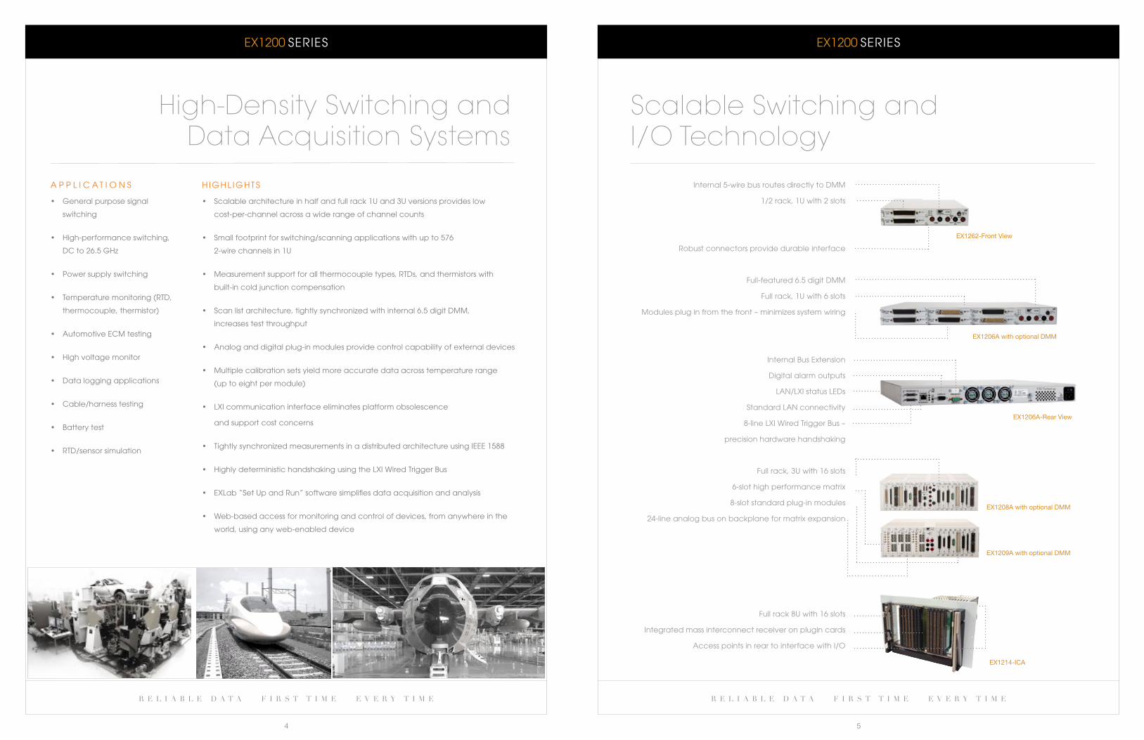
H I G H l I G H T S
• Scalablearchitectureinhalfandfullrack1Uand3Uversionsprovides low
cost-per-channel across a wide range of channel counts
• Smallfootprintforswitching/scanningapplications with up to 576
2-wire channels in 1U
• Measurementsupportforallthermocouple types, RTDs, and thermistors with
built-in cold junction compensation
• Scanlistarchitecture,tightlysynchronized with internal 6.5 digit DMM,
increases test throughput
• Analoganddigitalplug-inmodulesprovidecontrolcapabilityofexternaldevices
• Multiplecalibrationsetsyield more accurate data across temperature range
(up to eight per module)
• LXIcommunication interface eliminates platform obsolescence
and support cost concerns
• TightlysynchronizedmeasurementsinadistributedarchitectureusingIEEE1588
• HighlydeterministichandshakingusingtheLXIWiredTriggerBus
• EXLab“SetUpandRun”softwaresimplifiesdataacquisitionandanalysis
• Web-basedaccessformonitoring and control of devices, from anywhere in the
world, using any web-enabled device
a P P l I c a T I O N S
• Generalpurposesignal
switching
• High-performanceswitching,
Dc to 26.5 GHz
• Powersupplyswitching
• Temperaturemonitoring(RTD,
thermocouple, thermistor)
• AutomotiveECMtesting
• Highvoltagemonitor
• Dataloggingapplications
• Cable/harnesstesting
• Batterytest
• RTD/sensorsimulation
High-Density Switching and Data Acquisition Systems
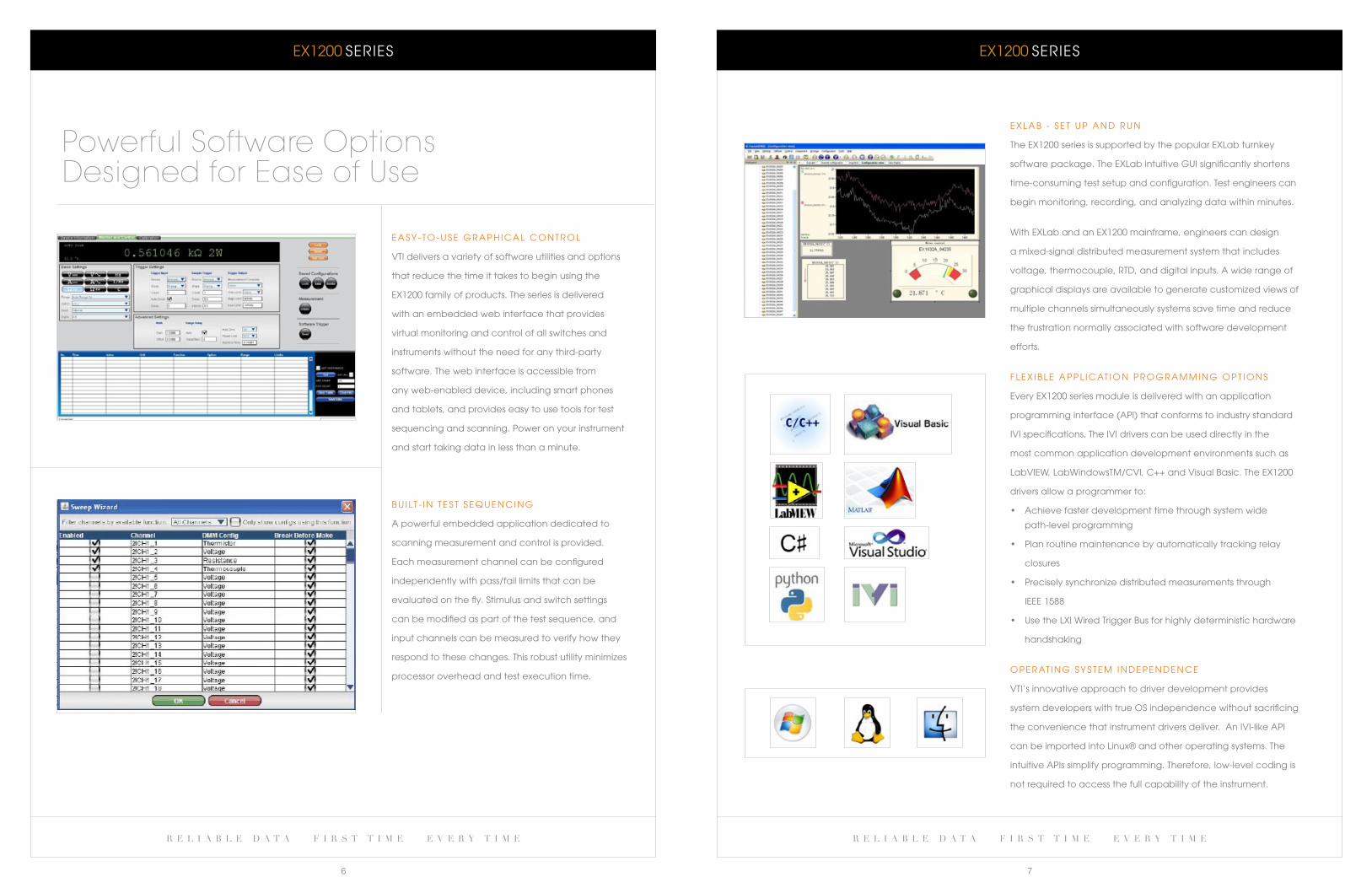
Scalable Switching and I/O Technology
Internal 5-wire bus routes directly to DMM
1/2 rack, 1U with 2 slots
Robust connectors provide durable interface
Full-featured 6.5 digit DMM
Full rack, 1U with 6 slots
Modules plug in from the front – minimizes system wiring
Internal bus extension
Digital alarm outputs
laN/lXI status leDs
Standard laN connectivity
8-lineLXIWiredTriggerBus–
precision hardware handshaking
Full rack, 3U with 16 slots
6-slot high performance matrix
8-slotstandardplug-inmodules
24-line analog bus on backplane for matrix expansion
Fullrack8Uwith16slots
Integrated mass interconnect receiver on plugin cards
access points in rear to interface with I/O
EX1206A-Rear View
EX1206A with optional DMM
EX1262-Front View
EX1214-ICA
EX1208A with optional DMM
EX1209A with optional DMM
eX1200 SeRIeS eX1200 SeRIeS
r e l i a b l e d a t a f i r s t t i m e e v e r y t i m e r e l i a b l e d a t a f i r s t t i m e e v e r y t i m e
6 7
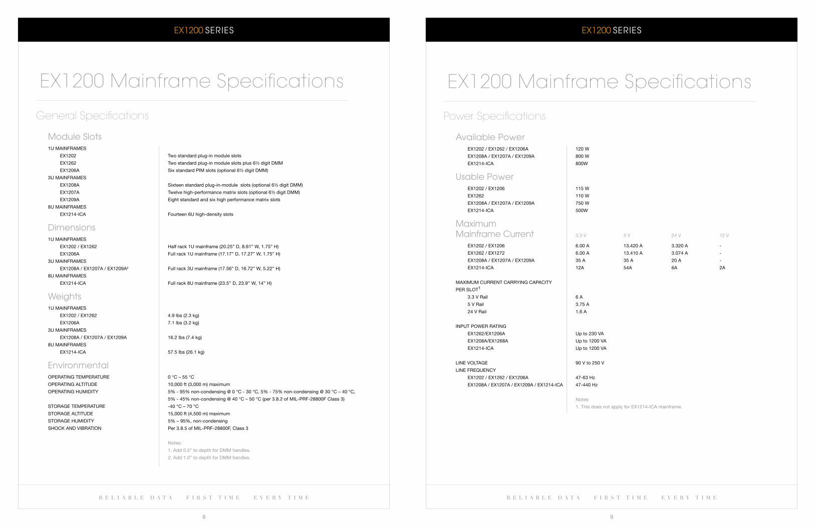
e a S Y - T O - U S e G R a P H I c a l c O N T R O l
VTI delivers a variety of software utilities and options
that reduce the time it takes to begin using the
eX1200 family of products. The series is delivered
with an embedded web interface that provides
virtual monitoring and control of all switches and
instruments without the need for any third-party
software. The web interface is accessible from
any web-enabled device, including smart phones
and tablets, and provides easy to use tools for test
sequencing and scanning. Power on your instrument
and start taking data in less than a minute.
b U I lT - I N T e S T S e q U e N c I N G
a powerful embedded application dedicated to
scanning measurement and control is provided.
each measurement channel can be configured
independently with pass/fail limits that can be
evaluated on the fly. Stimulus and switch settings
can be modified as part of the test sequence, and
input channels can be measured to verify how they
respond to these changes. This robust utility minimizes
processor overhead and test execution time.
Powerful Software Options Designed for Ease of Use
e X l a b - S e T U P a N D R U N
The eX1200 series is supported by the popular eXlab turnkey
software package. The eXlab intuitive GUI significantly shortens
time-consuming test setup and configuration. Test engineers can
begin monitoring, recording, and analyzing data within minutes.
with eXlab and an eX1200 mainframe, engineers can design
a mixed-signal distributed measurement system that includes
voltage, thermocouple, RTD, and digital inputs. a wide range of
graphical displays are available to generate customized views of
multiple channels simultaneously systems save time and reduce
the frustration normally associated with software development
efforts.
F l e X I b l e a P P l I c aT I O N P R O G R a M M I N G O P T I O N S
every eX1200 series module is delivered with an application
programming interface (aPI) that conforms to industry standard
IVI specifications. The IVI drivers can be used directly in the
most common application development environments such as
LabVIEW,LabWindowsTM/CVI,C++andVisualBasic.TheEX1200
drivers allow a programmer to:
• Achievefasterdevelopmenttimethroughsystemwide
path-level programming
• Planroutinemaintenancebyautomaticallytrackingrelay
closures
• Preciselysynchronizedistributedmeasurementsthrough
IEEE1588
• UsetheLXIWiredTriggerBusforhighlydeterministichardware
handshaking
O P e R aT I N G S Y S T e M I N D e P e N D e N c e
VTI’s innovative approach to driver development provides
system developers with true OS independence without sacrificing
the convenience that instrument drivers deliver. an IVI-like aPI
can be imported into linux® and other operating systems. The
intuitive aPIs simplify programming. Therefore, low-level coding is
not required to access the full capability of the instrument.
eX1200 SeRIeS eX1200 SeRIeS
r e l i a b l e d a t a f i r s t t i m e e v e r y t i m e r e l i a b l e d a t a f i r s t t i m e e v e r y t i m e
8 9
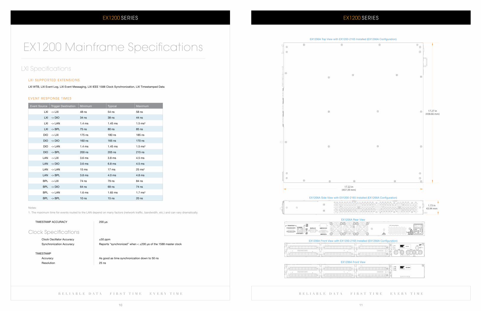
Module Slots1U MainfraMes
eX1202 Two standard plug-in module slots
eX1262 Two standard plug-in module slots plus 6½ digit DMM
eX1206a six standard PiM slots (optional 6½ digit DMM)
3U MainfraMes
eX1208a sixteen standard plug-in-module slots (optional 6½ digit DMM)
eX1207a Twelve high-performance matrix slots (optional 6½ digit DMM)
eX1209a eight standard and six high performance matrix slots
8U MainfraMes
eX1214-iCa fourteen 6U high-density slots
Dimensions1U MainfraMes
eX1202 / eX1262 Half rack 1U mainframe (20.25” D, 8.61” W, 1.75” H)
eX1206a full rack 1U mainframe (17.17” D, 17.27” W, 1.75” H)
3U MainfraMes
eX1208a / eX1207a / eX1209a² full rack 3U mainframe (17.56” D, 16.72” W, 5.22” H)
8U MainfraMes
eX1214-iCa full rack 8U mainframe (23.5’’ D, 23.9’’ W, 14’’ H)
weights1U MainfraMes
eX1202 / eX1262 4.9 lbs (2.3 kg)
eX1206a 7.1 lbs (3.2 kg)
3U MainfraMes
eX1208a / eX1207a / eX1209a 16.2 lbs (7.4 kg)
8U MainfraMes
eX1214-iCa 57.5 lbs (26.1 kg)
environmentalOPeraTing TeMPeraTUre 0 °C – 55 °C
OPeraTing alTiTUDe 10,000 ft (3,000 m) maximum
OPeraTing HUMiDiTy 5% - 95% non-condensing @ 0 °C - 30 °C, 5% - 75% non-condensing @ 30 °C – 40 °C,
5% - 45% non-condensing @ 40 °C – 50 °C (per 3.8.2 of Mil-Prf-28800f Class 3)
sTOrage TeMPeraTUre -40 °C – 70 °C
sTOrage alTiTUDe 15,000 ft (4,500 m) maximum
sTOrage HUMiDiTy 5% – 95%, non-condensing
sHOCk anD VibraTiOn Per 3.8.5 of Mil-Prf-28800f, Class 3
notes:
1. add 0.5” to depth for DMM handles.
2. add 1.0” to depth for DMM handles.
General Specifications
EX1200 Mainframe Specifications
available Power eX1202 / eX1262 / eX1206a 120 W
eX1208a / eX1207a / eX1209a 800 W
eX1214-iCa 800W
Usable Power eX1202 / eX1206 115 W
eX1262 110 W
eX1208a / eX1207a / eX1209a 750 W
eX1214-iCa 500W
Maximum Mainframe current 3.3 V 5 V 24 V 12 V
eX1202 / eX1206 6.00 a 13.420 a 3.320 a -
eX1262 / eX1272 6.00 a 13.410 a 3.074 a -
eX1208a / eX1207a / eX1209a 35 a 35 a 20 a -
eX1214-iCa 12a 54a 6a 2a
MaXiMUM CUrrenT Carrying CaPaCiTy
Per slOT1
3.3 V rail 6 a
5 V rail 3.75 a
24 V rail 1.6 a
inPUT POWer raTing
eX1262/eX1206a Up to 230 Va
eX1208a/eX1268a Up to 1200 Va
eX1214-iCa Up to 1200 Va
line VOlTage 90 V to 250 V
line freqUenCy
eX1202 / eX1262 / eX1206a 47-63 Hz
eX1208a / eX1207a / eX1209a / eX1214-iCa 47-440 Hz
notes:
1. This does not apply for eX1214-iCa mainframe.
Power Specifications
EX1200 Mainframe Specifications
eX1200 SeRIeS eX1200 SeRIeS
r e l i a b l e d a t a f i r s t t i m e e v e r y t i m e r e l i a b l e d a t a f i r s t t i m e e v e r y t i m e
10 11
l X I S U P P O R T e D e X T e N S I O N S
lXi WTb, lXi event log, lXi event Messaging, lXi ieee 1588 Clock synchronization, lXi Timestamped Data
e V e N T R e S P O N S e T I M e S
event source Trigger Destination Minimum Typical Maximum
lXi -> lXi 48 ns 54 ns 58 ns
lXi -> DiO 34 ns 38 ns 44 ns
lXi -> lan 1.4 ms 1.45 ms 1.5 ms¹
lXi -> bPl 75 ns 80 ns 85 ns
DiO -> lXi 175 ns 180 ns 185 ns
DiO -> DiO 160 ns 165 ns 170 ns
DiO -> lan 1.4 ms 1.45 ms 1.5 ms¹
DiO -> bPl 200 ns 205 ns 215 ns
lan -> lXi 3.6 ms 3.8 ms 4.5 ms
lan -> DiO 3.6 ms 6.8 ms 4.5 ms
lan -> lan 15 ms 17 ms 25 ms¹
lan -> bPl 3.8 ms 4.0 ms 4.8 ms
bPl -> lXi 74 ns 79 ns 84 ns
bPl -> DiO 64 ns 69 ns 74 ns
bPl -> lan 1.6 ms 1.65 ms 1.7 ms¹
bPl -> bPl 10 ns 15 ns 20 ns
notes:
1. The maximum time for events routed to the lan depend on many factors (network traffic, bandwidth, etc.) and can vary dramatically.
TiMesTaMP aCCUraCy 200 μs
clock Specifications Clock Oscillator accuracy ±50 ppm
synchronization accuracy reports “synchronized” when < ±200 μs of the 1588 master clock
TiMesTaMP
accuracy as good as time synchronization down to 50 ns
resolution 25 ns
LXI Specifications
EX1200 Mainframe Specifications
17.27 in(438.66 mm)
17.22 in(437.39 mm)
EX1206A Top View with EX1200-2165 Installed (EX1266A Configuration)
1.73 in43.94 mm
EX1206A Side View with EX1200-2165 Installed (EX1266A Configuration)
VT I I n s t r ument sTRIGGER BUS
DIGITAL I/O ETHERNET
10/100 BASE-T 90-250 VAC 50 / 60 Hz
120VA MAX.
1588 LAN PWR
LAN RST DMM BUS IN
DMM BUS OUT SYS RST
!
EX1206A Rear View
1588
LAN
PWR
EX1206A
EX1206A Front View
EX1206A Front View with EX1200-2165 Installed (EX1266A Configuration)
1588
LAN
PWR SENSE
Ω 4 WIRE HI LO 300 VDC
300 VAC
INPUT V
3A RMS
INPUT
I
I
3A, 250V
CAT- I
I FUSE
425 Vpk
HI LO
!
EX1266A
eX1200 SeRIeS eX1200 SeRIeS
r e l i a b l e d a t a f i r s t t i m e e v e r y t i m e r e l i a b l e d a t a f i r s t t i m e e v e r y t i m e
12 13
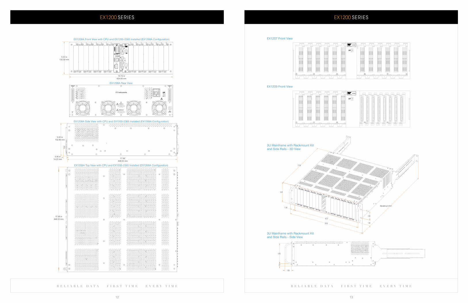
EX1208A Top View with CPU and EX1200-2365 Installed (EX1268A Configuration)
0.56 in
14.23 mm
5.22 in
132.89 mm
EX1208A Side View with CPU and EX1200-2365 Installed (EX1268A Configuration)
17.56”
446.03 mm
1588
LAN
PWR
MATRIX BUSINPUT
MATRIX BUSOUTPUT
DMM BUS IN
DMM BUS OUT!
!
17.56 in
446.03 mm
EX1208A Rear View
5.22 in
132.59 mm
16.72 in
424.69 mm
EX1208A Front View with CPU and EX1200-2365 Installed (EX1268A Configuration)
TRIGGERBUS
PWR1588LAN
CEL - 4
1 2 3 5 6 7 84 9 10 11 13 14 15 1612
HI
HI
GUARD
E1200-2365
PWR
LANLAN
1588
EX1207
EX1209
PWR
LANLAN
1588
19.00
5.22
1.48
2.26
17.56
Adjustable up to 30.0"
16.72
1.140
1.39
.47
4.28
1.39
.47
4.28
3U Mainframe with rackmount kit and side rails - 3D View
eX1207 front View
eX1209 front View
3U Mainframe with rackmount kit and side rails - side View
eX1200 SeRIeS eX1200 SeRIeS
r e l i a b l e d a t a f i r s t t i m e e v e r y t i m e r e l i a b l e d a t a f i r s t t i m e e v e r y t i m e
14 15
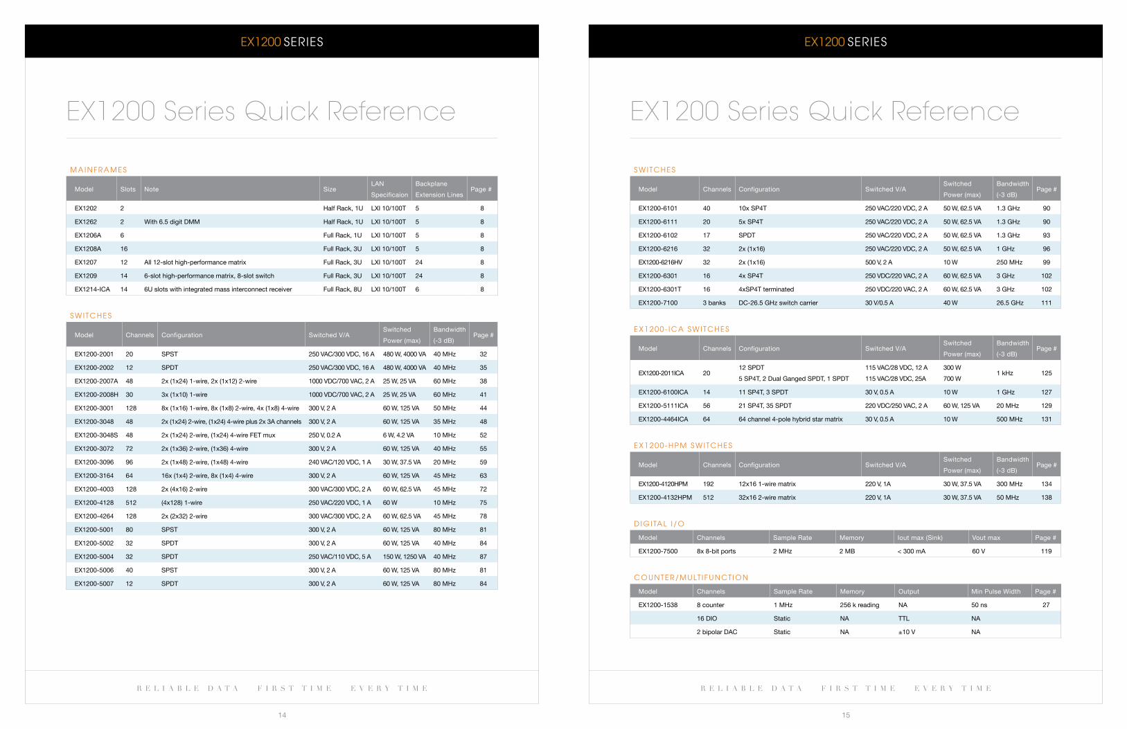
M a I N F R a M e S
Model slots note sizelan
specificaion
backplane
extension linesPage #
eX1202 2 Half rack, 1U lXi 10/100T 5 8
eX1262 2 With 6.5 digit DMM Half rack, 1U lXi 10/100T 5 8
eX1206a 6 full rack, 1U lXi 10/100T 5 8
eX1208a 16 full rack, 3U lXi 10/100T 5 8
eX1207 12 all 12-slot high-performance matrix full rack, 3U lXi 10/100T 24 8
eX1209 14 6-slot high-performance matrix, 8-slot switch full rack, 3U lXi 10/100T 24 8
eX1214-iCa 14 6U slots with integrated mass interconnect receiver full rack, 8U lXi 10/100T 6 8
S w I T c H e S
Model Channels Configuration switched V/aswitched
Power (max)
bandwidth
(-3 db)Page #
eX1200-2001 20 sPsT 250 VaC/300 VDC, 16 a 480 W, 4000 Va 40 MHz 32
eX1200-2002 12 sPDT 250 VaC/300 VDC, 16 a 480 W, 4000 Va 40 MHz 35
eX1200-2007a 48 2x (1x24) 1-wire, 2x (1x12) 2-wire 1000 VDC/700 VaC, 2 a 25 W, 25 Va 60 MHz 38
eX1200-2008H 30 3x (1x10) 1-wire 1000 VDC/700 VaC, 2 a 25 W, 25 Va 60 MHz 41
eX1200-3001 128 8x (1x16) 1-wire, 8x (1x8) 2-wire, 4x (1x8) 4-wire 300 V, 2 a 60 W, 125 Va 50 MHz 44
eX1200-3048 48 2x (1x24) 2-wire, (1x24) 4-wire plus 2x 3a channels 300 V, 2 a 60 W, 125 Va 35 MHz 48
eX1200-3048s 48 2x (1x24) 2-wire, (1x24) 4-wire feT mux 250 V, 0.2 a 6 W, 4.2 Va 10 MHz 52
eX1200-3072 72 2x (1x36) 2-wire, (1x36) 4-wire 300 V, 2 a 60 W, 125 Va 40 MHz 55
eX1200-3096 96 2x (1x48) 2-wire, (1x48) 4-wire 240 VaC/120 VDC, 1 a 30 W, 37.5 Va 20 MHz 59
eX1200-3164 64 16x (1x4) 2-wire, 8x (1x4) 4-wire 300 V, 2 a 60 W, 125 Va 45 MHz 63
eX1200-4003 128 2x (4x16) 2-wire 300 VaC/300 VDC, 2 a 60 W, 62.5 Va 45 MHz 72
eX1200-4128 512 (4x128) 1-wire 250 VaC/220 VDC, 1 a 60 W 10 MHz 75
eX1200-4264 128 2x (2x32) 2-wire 300 VaC/300 VDC, 2 a 60 W, 62.5 Va 45 MHz 78
eX1200-5001 80 sPsT 300 V, 2 a 60 W, 125 Va 80 MHz 81
eX1200-5002 32 sPDT 300 V, 2 a 60 W, 125 Va 40 MHz 84
eX1200-5004 32 sPDT 250 VaC/110 VDC, 5 a 150 W, 1250 Va 40 MHz 87
eX1200-5006 40 sPsT 300 V, 2 a 60 W, 125 Va 80 MHz 81
eX1200-5007 12 sPDT 300 V, 2 a 60 W, 125 Va 80 MHz 84
EX1200 Series Quick Reference
S w I T c H e S
Model Channels Configuration switched V/aswitched
Power (max)
bandwidth
(-3 db)Page #
eX1200-6101 40 10x sP4T 250 VaC/220 VDC, 2 a 50 W, 62.5 Va 1.3 gHz 90
eX1200-6111 20 5x sP4T 250 VaC/220 VDC, 2 a 50 W, 62.5 Va 1.3 gHz 90
eX1200-6102 17 sPDT 250 VaC/220 VDC, 2 a 50 W, 62.5 Va 1.3 gHz 93
eX1200-6216 32 2x (1x16) 250 VaC/220 VDC, 2 a 50 W, 62.5 Va 1 gHz 96
eX1200-6216HV 32 2x (1x16) 500 V, 2 a 10 W 250 MHz 99
eX1200-6301 16 4x sP4T 250 VDC/220 VaC, 2 a 60 W, 62.5 Va 3 gHz 102
eX1200-6301T 16 4xsP4T terminated 250 VDC/220 VaC, 2 a 60 W, 62.5 Va 3 gHz 102
eX1200-7100 3 banks DC-26.5 gHz switch carrier 30 V/0.5 a 40 W 26.5 gHz 111
e X 1 2 0 0 - I c a S w I T c H e S
Model Channels Configuration switched V/aswitched
Power (max)
bandwidth
(-3 db)Page #
eX1200-2011iCa 2012 sPDT
5 sP4T, 2 Dual ganged sPDT, 1 sPDT
115 VaC/28 VDC, 12 a
115 VaC/28 VDC, 25a
300 W
700 W1 kHz 125
eX1200-6100iCa 14 11 sP4T, 3 sPDT 30 V, 0.5 a 10 W 1 gHz 127
eX1200-5111iCa 56 21 sP4T, 35 sPDT 220 VDC/250 VaC, 2 a 60 W, 125 Va 20 MHz 129
eX1200-4464iCa 64 64 channel 4-pole hybrid star matrix 30 V, 0.5 a 10 W 500 MHz 131
e X 1 2 0 0 - H P M S w I T c H e S
Model Channels Configuration switched V/aswitched
Power (max)
bandwidth
(-3 db)Page #
eX1200-4120HPM 192 12x16 1-wire matrix 220 V, 1a 30 W, 37.5 Va 300 MHz 134
eX1200-4132HPM 512 32x16 2-wire matrix 220 V, 1a 30 W, 37.5 Va 50 MHz 138
D I G I Ta l I / O
Model Channels sample rate Memory iout max (sink) Vout max Page #
eX1200-7500 8x 8-bit ports 2 MHz 2 Mb < 300 ma 60 V 119
c O U N T e R / M U lT I F U N c T I O N
Model Channels sample rate Memory Output Min Pulse Width Page #
eX1200-1538 8 counter 1 MHz 256 k reading na 50 ns 27
16 DiO static na TTl na
2 bipolar DaC static na ±10 V na
EX1200 Series Quick Reference
w w w . v t i i n s t r u m e n t s . c o m
D a T a S H e e T
r e l i a b l e d a t a f i r s t t i m e e v e r y t i m e
17
eX1200 SeRIeS
r e l i a b l e d a t a f i r s t t i m e e v e r y t i m e
16
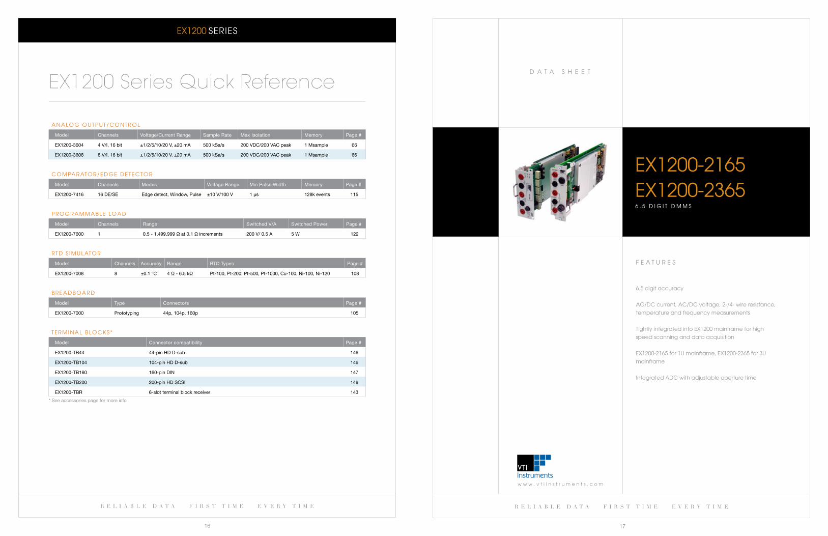
a N a l O G O U T P U T / c O N T R O l
Model Channels Voltage/Current range sample rate Max isolation Memory Page #
eX1200-3604 4 V/i, 16 bit ±1/2/5/10/20 V, ±20 ma 500 ksa/s 200 VDC/200 VaC peak 1 Msample 66
eX1200-3608 8 V/i, 16 bit ±1/2/5/10/20 V, ±20 ma 500 ksa/s 200 VDC/200 VaC peak 1 Msample 66
c O M Pa R aT O R / e D G e D e T e c T O R
Model Channels Modes Voltage range Min Pulse Width Memory Page #
eX1200-7416 16 De/se edge detect, Window, Pulse ±10 V/100 V 1 μs 128k events 115
P R O G R a M M a b l e l O a D
Model Channels range switched V/a switched Power Page #
eX1200-7600 1 0.5 - 1,499,999 Ω at 0.1 Ω increments 200 V/ 0.5 a 5 W 122
R T D S I M U l aT O R
Model Channels accuracy range rTD Types Page #
eX1200-7008 8 ±0.1 °C 4 Ω - 6.5 kΩ Pt-100, Pt-200, Pt-500, Pt-1000, Cu-100, ni-100, ni-120 108
b R e a D b O a R D
Model Type Connectors Page #
eX1200-7000 Prototyping 44p, 104p, 160p 105
T e R M I N a l b l O c k S *
Model Connector compatibility Page #
eX1200-Tb44 44-pin HD D-sub 146
eX1200-Tb104 104-pin HD D-sub 146
eX1200-Tb160 160-pin Din 147
eX1200-Tb200 200-pin HD sCsi 148
eX1200-Tbr 6-slot terminal block receiver 143
* see accessories page for more info
EX1200 Series Quick Reference
F e a T U R e S
6.5 digit accuracy
ac/Dc current, ac/Dc voltage, 2-/4- wire resistance,
temperature and frequency measurements
Tightly integrated into eX1200 mainframe for high
speed scanning and data acquisition
eX1200-2165 for 1U mainframe, eX1200-2365 for 3U
mainframe
Integrated aDc with adjustable aperture time
eX1200-2165eX1200-23656 . 5 D I G I T D M M S
r e l i a b l e d a t a f i r s t t i m e e v e r y t i m e r e l i a b l e d a t a f i r s t t i m e e v e r y t i m e
18 19
eX1200-2165 / eX1200-2365 6.5 Digit DMMs
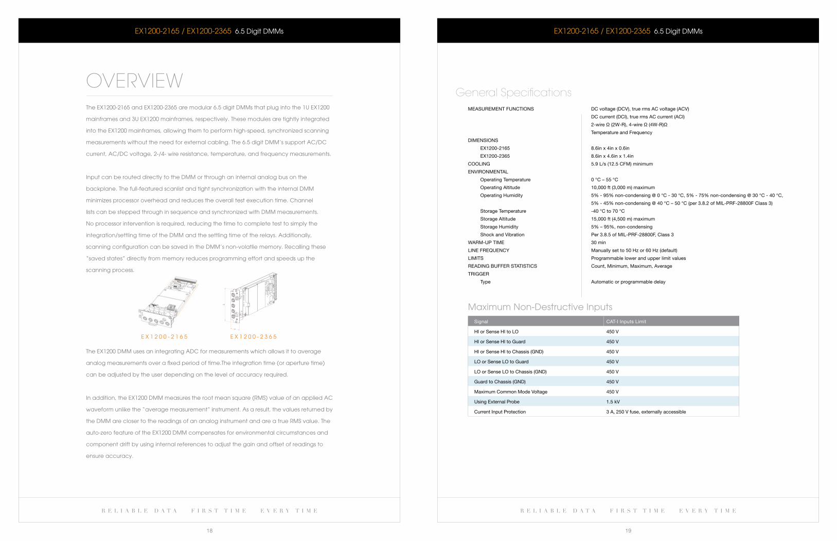
OVERVIEWThe eX1200-2165 and eX1200-2365 are modular 6.5 digit DMMs that plug into the 1U eX1200
mainframes and 3U eX1200 mainframes, respectively. These modules are tightly integrated
into the eX1200 mainframes, allowing them to perform high-speed, synchronized scanning
measurements without the need for external cabling. The 6.5 digit DMM’s support ac/Dc
current, ac/Dc voltage, 2-/4- wire resistance, temperature, and frequency measurements.
Input can be routed directly to the DMM or through an internal analog bus on the
backplane. The full-featured scanlist and tight synchronization with the internal DMM
minimizes processor overhead and reduces the overall test execution time. channel
lists can be stepped through in sequence and synchronized with DMM measurements.
No processor intervention is required, reducing the time to complete test to simply the
integration/settling time of the DMM and the settling time of the relays. additionally,
scanning configuration can be saved in the DMM’s non-volatlie memory. Recalling these
“saved states” directly from memory reduces programming effort and speeds up the
scanning process.
The eX1200 DMM uses an integrating aDc for measurements which allows it to average
analog measurements over a fixed period of time.The integration time (or aperture time)
can be adjusted by the user depending on the level of accuracy required.
In addition, the eX1200 DMM measures the root mean square (RMS) value of an applied ac
waveform unlike the “average measurement” instrument. as a result, the values returned by
the DMM are closer to the readings of an analog instrument and are a true RMS value. The
auto-zero feature of the eX1200 DMM compensates for environmental circumstances and
component drift by using internal references to adjust the gain and offset of readings to
ensure accuracy.
4.59
.961.36
4.59
eX1200-2165 / eX1200-2365 6.5 Digit DMMs
MeasUreMenT fUnCTiOns DC voltage (DCV), true rms aC voltage (aCV)
DC current (DCi), true rms aC current (aCi)
2-wire Ω (2W-r), 4-wire Ω (4W-r)Ω
Temperature and frequency
DiMensiOns
eX1200-2165 8.6in x 4in x 0.6in
eX1200-2365 8.6in x 4.6in x 1.4in
COOling 5.9 l/s (12.5 CfM) minimum
enVirOnMenTal
Operating Temperature 0 °C – 55 °C
Operating altitude 10,000 ft (3,000 m) maximum
Operating Humidity 5% - 95% non-condensing @ 0 °C - 30 °C, 5% - 75% non-condensing @ 30 °C - 40 °C,
5% - 45% non-condensing @ 40 °C – 50 °C (per 3.8.2 of Mil-Prf-28800f Class 3)
storage Temperature -40 °C to 70 °C
storage altitude 15,000 ft (4,500 m) maximum
storage Humidity 5% – 95%, non-condensing
shock and Vibration Per 3.8.5 of Mil-Prf-28800f, Class 3
WarM-UP TiMe 30 min
line freqUenCy Manually set to 50 Hz or 60 Hz (default)
liMiTs Programmable lower and upper limit values
reaDing bUffer sTaTisTiCs Count, Minimum, Maximum, average
Trigger
Type automatic or programmable delay
Maximum Non-Destructive Inputs
signal CaT-i inputs limit
Hi or sense Hi to lO 450 V
Hi or sense Hi to guard 450 V
Hi or sense Hi to Chassis (gnD) 450 V
lO or sense lO to guard 450 V
lO or sense lO to Chassis (gnD) 450 V
guard to Chassis (gnD) 450 V
Maximum Common Mode Voltage 450 V
Using external Probe 1.5 kV
Current input Protection 3 a, 250 V fuse, externally accessible
General Specifications
e X 1 2 0 0 - 2 3 6 5e X 1 2 0 0 - 2 1 6 5
r e l i a b l e d a t a f i r s t t i m e e v e r y t i m e r e l i a b l e d a t a f i r s t t i m e e v e r y t i m e
20 21
eX1200-2165 / eX1200-2365 6.5 Digit DMMs
Dc Voltage - 1 Year accuracy
range resolution input resistance¹T
Cal ±5 °C
% reading % range
0 °C to ±55 °C
≤ 30% range > 30% range
100 mV, 6½ digit 0.01 μV 10 gΩ / 10 MΩ 0.0150% 0.0060% ±15.0 μV ±30.0 μV
1 V, 6½ digit 1 μV 10 gΩ / 10 MΩ 0.0060% 0.0010% ±30.0 μV ±300.0 μV
10 V, 6½ digit 10 μV 10 gΩ / 10 MΩ 0.0035% 0.0007% ±300.0 μV ±3.0 mV
100 V, 6½ digit 100 μV 10 MΩ 0.0050% 0.0009% ±3.0 mV ±30.0 mV
300 V, 6½ digit 100 μV 10 MΩ 0.0055% 0.0035% ±30.0 mV ±30.0 mV
100 mV, 5½ digit 1.00 μV 10 gΩ / 10 MΩ 0.0150% 0.0068% ±15.3 μV ±33.0 μV
1 V, 5½ digit 10.00 μV 10 gΩ / 10 MΩ 0.0060% 0.0011% ±33.0 μV ±330.0 μV
10 V, 5½ digit 100.00 μV 10 gΩ / 10 MΩ 0.0035% 0.0008% ±330.0 μV ±3.3 mV
100 V, 5½ digit 1.00 mV 10 MΩ 0.0050% 0.0010% ±3.3 mV ±33.0 mV
300 V, 5½ digit 1.00 mV 10 MΩ 0.0055% 0.0037% ±33.0 mV ±33.0 mV
100 mV, 4½ digit 10.00 μV 10 gΩ / 10 MΩ 0.0150% 0.0075% ±15.6 μV ±36.0 μV
1 V, 4½ digit 100.00 μV 10 gΩ / 10 MΩ 0.0060% 0.0012% ±36.0 μV ±360.0 μV
10 V, 4½ digit 100 mV 10 gΩ / 10 MΩ 0.0035% 0.0009% ±360.0 μV ±3.6 mV
100 V, 4½ digit 10.00 mV 10 MΩ 0.0050% 0.0011% ±3.6 mV ±36.0 mV
300 V, 4½ digit 10.00 mV 10 MΩ 0.0055% 0.0040% ±36.0 mV ±36.0 mV
notes: 1. selectable input resistance to support external high-voltage probe. 10 gΩ Typical; > 1 gΩ Worst Case - 10.0 MΩ 1%. Over-range: 20% of range, except 300 V range. normal Mode rejection ratio (nMrr) at power line frequency 0.1%: 60 db for 1 PlC, 10 PlC, 100 PlC. Common Mode rejection ratio (CMrr): 140 db at DC. input bias current: <100 pa typical at 23 °C.
Dc current - 1 Year accuracy
range resolutionMaximum burden
Voltage*
TCal
±5 °C
% reading % range
0 °C to ±55 °C
≤ 30% range > 30% range
1 ma, 6½ digit 1 na <0.1 V 0.0500% 0.0100% ±396 na ±4.35 μa
10 ma, 6½ digit 10 na <0.1 V 0.0500% 0.0060% ±4.35 μa ±43.5 μa
100 ma, 6½ digit 100 na <0.6 V 0.0500% 0.0060% ±43.5 μa ±435 μa
1 a, 6½ digit 1 μa <0.4 V 0.0700% 0.0070% ±435 μa ±4.40 ma
3 a, 6½ digit 1 μa <0.9 V *0.1000% 0.0060% ±4.40 ma ±4.40 ma
1 ma, 5½ digit 10.0 na <0.1 V 0.0500% 0.0105% ±399 na ±4.38 μa
10 ma, 5½ digit 100.0 na <0.1 V 0.0500% 0.0061% ±4.38 μa ±43.8 μa
100 ma, 5½ digit 1.0 μa <0.6 V 0.0500% 0.0061% ±43.8 μa ±438 μa
1 a, 5½ digit 10.0 μa <0.4 V 0.0700% 0.0072% ±438 μa ±4.42 ma
3 a, 5½ digit 10.0 μa <0.9 V *0.1000% 0.0061% ±4.42 ma ±4.42 ma
1 ma, 4½ digit 100.0 na <0.1 V 0.0500% 0.0110% ±402 na ±4.41 μa
10 ma, 4½ digit 1.0 μa <0.1 V 0.0500% 0.0062% ±4.41 μa ±44.1 μa
100 ma, 4½ digit 10.0 μa <0.6 V 0.0500% 0.0062% ±44.1 μa ±441 μa
1 a, 4½ digit 100.0 μa <0.4 V 0.0700% 0.0073% ±441 μa ±4.44 ma
3 a, 4½ digit 100.0 μa <0.9 V *0.1000% 0.0062% ±4.44 ma ±4.44 ma
notes: * add 0.15% of reading above 2 a. Over-range: 20% of range, except 3 a range.
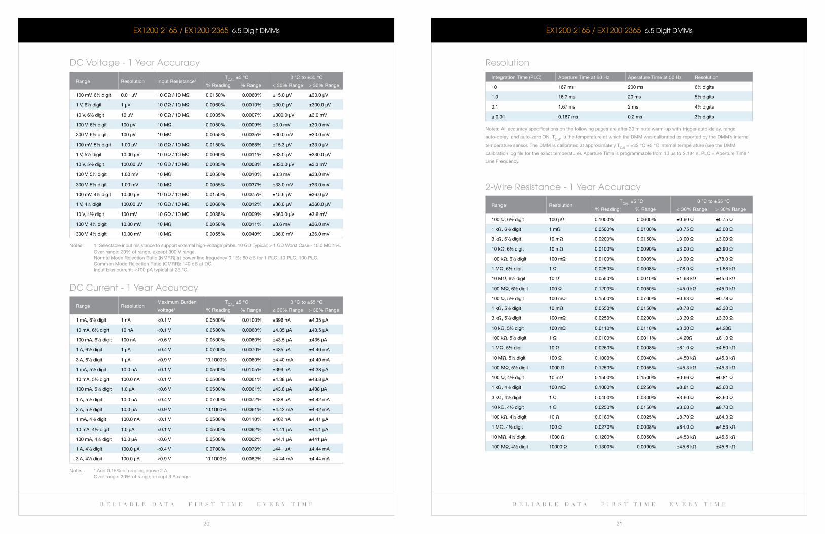
Resolution
integration Time (PlC) aperture Time at 60 Hz aperature Time at 50 Hz resolution
10 167 ms 200 ms 6½ digits
1.0 16.7 ms 20 ms 5½ digits
0.1 1.67 ms 2 ms 4½ digits
≤ 0.01 0.167 ms 0.2 ms 3½ digits
notes: all accuracy specifications on the following pages are after 30 minute warm-up with trigger auto-delay, range
auto-delay, and auto-zero On. TCal
, is the temperature at which the DMM was calibrated as reported by the DMM’s internal
temperature sensor. The DMM is calibrated at approximately TCal
= ±32 °C ±5 °C internal temperature (see the DMM
calibration log file for the exact temperature). aperture Time is programmable from 10 μs to 2.184 s. PlC = aperture Time *
line frequency.
2-wire Resistance - 1 Year accuracy
range resolutionT
Cal ±5 °C
% reading % range
0 °C to ±55 °C
≤ 30% range > 30% range
100 Ω, 6½ digit 100 μΩ 0.1000% 0.0600% ±0.60 Ω ±0.75 Ω
1 kΩ, 6½ digit 1 mΩ 0.0500% 0.0100% ±0.75 Ω ±3.00 Ω
3 kΩ, 6½ digit 10 mΩ 0.0200% 0.0150% ±3.00 Ω ±3.00 Ω
10 kΩ, 6½ digit 10 mΩ 0.0100% 0.0090% ±3.00 Ω ±3.90 Ω
100 kΩ, 6½ digit 100 mΩ 0.0100% 0.0009% ±3.90 Ω ±78.0 Ω
1 MΩ, 6½ digit 1 Ω 0.0250% 0.0008% ±78.0 Ω ±1.68 kΩ
10 MΩ, 6½ digit 10 Ω 0.0550% 0.0010% ±1.68 kΩ ±45.0 kΩ
100 MΩ, 6½ digit 100 Ω 0.1200% 0.0050% ±45.0 kΩ ±45.0 kΩ
100 Ω, 5½ digit 100 mΩ 0.1500% 0.0700% ±0.63 Ω ±0.78 Ω
1 kΩ, 5½ digit 10 mΩ 0.0550% 0.0150% ±0.78 Ω ±3.30 Ω
3 kΩ, 5½ digit 100 mΩ 0.0250% 0.0200% ±3.30 Ω ±3.30 Ω
10 kΩ, 5½ digit 100 mΩ 0.0110% 0.0110% ±3.30 Ω ±4.20Ω
100 kΩ, 5½ digit 1 Ω 0.0100% 0.0011% ±4.20Ω ±81.0 Ω
1 MΩ, 5½ digit 10 Ω 0.0260% 0.0008% ±81.0 Ω ±4.50 kΩ
10 MΩ, 5½ digit 100 Ω 0.1000% 0.0040% ±4.50 kΩ ±45.3 kΩ
100 MΩ, 5½ digit 1000 Ω 0.1250% 0.0055% ±45.3 kΩ ±45.3 kΩ
100 Ω, 4½ digit 10 mΩ 0.1500% 0.1500% ±0.66 Ω ±0.81 Ω
1 kΩ, 4½ digit 100 mΩ 0.1000% 0.0250% ±0.81 Ω ±3.60 Ω
3 kΩ, 4½ digit 1 Ω 0.0400% 0.0300% ±3.60 Ω ±3.60 Ω
10 kΩ, 4½ digit 1 Ω 0.0250% 0.0150% ±3.60 Ω ±8.70 Ω
100 kΩ, 4½ digit 10 Ω 0.0180% 0.0025% ±8.70 Ω ±84.0 Ω
1 MΩ, 4½ digit 100 Ω 0.0270% 0.0008% ±84.0 Ω ±4.53 kΩ
10 MΩ, 4½ digit 1000 Ω 0.1200% 0.0050% ±4.53 kΩ ±45.6 kΩ
100 MΩ, 4½ digit 10000 Ω 0.1300% 0.0090% ±45.6 kΩ ±45.6 kΩ
eX1200-2165 / eX1200-2365 6.5 Digit DMMs
r e l i a b l e d a t a f i r s t t i m e e v e r y t i m e r e l i a b l e d a t a f i r s t t i m e e v e r y t i m e
22 23
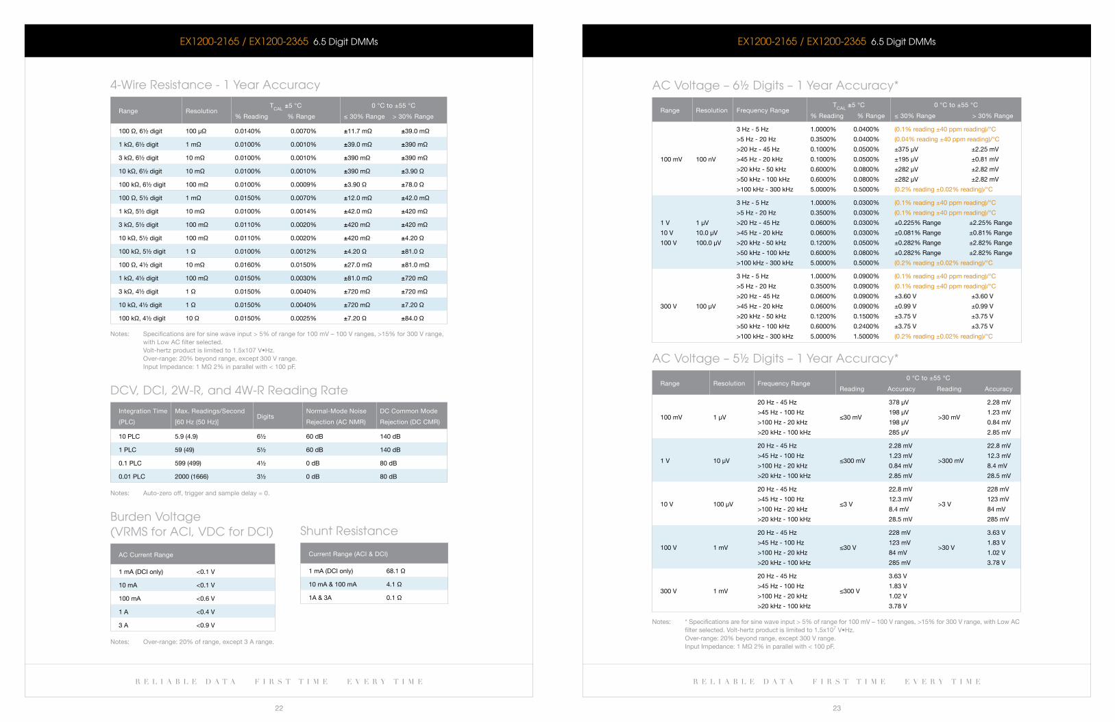
4-wire Resistance - 1 Year accuracy
range resolutionT
Cal ±5 °C
% reading % range
0 °C to ±55 °C
≤ 30% range > 30% range
100 Ω, 6½ digit 100 μΩ 0.0140% 0.0070% ±11.7 mΩ ±39.0 mΩ
1 kΩ, 6½ digit 1 mΩ 0.0100% 0.0010% ±39.0 mΩ ±390 mΩ
3 kΩ, 6½ digit 10 mΩ 0.0100% 0.0010% ±390 mΩ ±390 mΩ
10 kΩ, 6½ digit 10 mΩ 0.0100% 0.0010% ±390 mΩ ±3.90 Ω
100 kΩ, 6½ digit 100 mΩ 0.0100% 0.0009% ±3.90 Ω ±78.0 Ω
100 Ω, 5½ digit 1 mΩ 0.0150% 0.0070% ±12.0 mΩ ±42.0 mΩ
1 kΩ, 5½ digit 10 mΩ 0.0100% 0.0014% ±42.0 mΩ ±420 mΩ
3 kΩ, 5½ digit 100 mΩ 0.0110% 0.0020% ±420 mΩ ±420 mΩ
10 kΩ, 5½ digit 100 mΩ 0.0110% 0.0020% ±420 mΩ ±4.20 Ω
100 kΩ, 5½ digit 1 Ω 0.0100% 0.0012% ±4.20 Ω ±81.0 Ω
100 Ω, 4½ digit 10 mΩ 0.0160% 0.0150% ±27.0 mΩ ±81.0 mΩ
1 kΩ, 4½ digit 100 mΩ 0.0150% 0.0030% ±81.0 mΩ ±720 mΩ
3 kΩ, 4½ digit 1 Ω 0.0150% 0.0040% ±720 mΩ ±720 mΩ
10 kΩ, 4½ digit 1 Ω 0.0150% 0.0040% ±720 mΩ ±7.20 Ω
100 kΩ, 4½ digit 10 Ω 0.0150% 0.0025% ±7.20 Ω ±84.0 Ω
notes: specifications are for sine wave input > 5% of range for 100 mV – 100 V ranges, >15% for 300 V range, with low aC filter selected. Volt-hertz product is limited to 1.5x10⁷ V•Hz. Over-range: 20% beyond range, except 300 V range. input impedance: 1 MΩ 2% in parallel with < 100 pf.
DcV, DcI, 2w-R, and 4w-R Reading Rate
integration Time
(PlC)
Max. readings/second
[60 Hz (50 Hz)]Digits
normal-Mode noise
rejection (aC nMr)
DC Common Mode
rejection (DC CMr)
10 PlC 5.9 (4.9) 6½ 60 db 140 db
1 PlC 59 (49) 5½ 60 db 140 db
0.1 PlC 599 (499) 4½ 0 db 80 db
0.01 PlC 2000 (1666) 3½ 0 db 80 db
notes: auto-zero off, trigger and sample delay = 0.
burden Voltage (VRMS for acI, VDc for DcI)
aC Current range
1 ma (DCi only) <0.1 V
10 ma <0.1 V
100 ma <0.6 V
1 a <0.4 V
3 a <0.9 V
notes: Over-range: 20% of range, except 3 a range.
eX1200-2165 / eX1200-2365 6.5 Digit DMMs
Shunt Resistance
Current range (aCi & DCi)
1 ma (DCi only) 68.1 Ω
10 ma & 100 ma 4.1 Ω
1a & 3a 0.1 Ω
ac Voltage – 6½ Digits – 1 Year accuracy*
range resolution frequency rangeT
Cal ±5 °C
% reading % range
0 °C to ±55 °C
≤ 30% range > 30% range
100 mV 100 nV
3 Hz - 5 Hz
>5 Hz - 20 Hz
>20 Hz - 45 Hz
>45 Hz - 20 kHz
>20 kHz - 50 kHz
>50 kHz - 100 kHz
>100 kHz - 300 kHz
1.0000%
0.3500%
0.1000%
0.1000%
0.6000%
0.6000%
5.0000%
0.0400%
0.0400%
0.0500%
0.0500%
0.0800%
0.0800%
0.5000%
(0.1% reading ±40 ppm reading)/°C
(0.04% reading ±40 ppm reading)/°C
±375 μV ±2.25 mV
±195 μV ±0.81 mV
±282 μV ±2.82 mV
±282 μV ±2.82 mV
(0.2% reading ±0.02% reading)/°C
1 V
10 V
100 V
1 μV
10.0 μV
100.0 μV
3 Hz - 5 Hz
>5 Hz - 20 Hz
>20 Hz - 45 Hz
>45 Hz - 20 kHz
>20 kHz - 50 kHz
>50 kHz - 100 kHz
>100 kHz - 300 kHz
1.0000%
0.3500%
0.0600%
0.0600%
0.1200%
0.6000%
5.0000%
0.0300%
0.0300%
0.0300%
0.0300%
0.0500%
0.0800%
0.5000%
(0.1% reading ±40 ppm reading)/°C
(0.1% reading ±40 ppm reading)/°C
±0.225% range ±2.25% range
±0.081% range ±0.81% range
±0.282% range ±2.82% range
±0.282% range ±2.82% range
(0.2% reading ±0.02% reading)/°C
300 V 100 μV
3 Hz - 5 Hz
>5 Hz - 20 Hz
>20 Hz - 45 Hz
>45 Hz - 20 kHz
>20 kHz - 50 kHz
>50 kHz - 100 kHz
>100 kHz - 300 kHz
1.0000%
0.3500%
0.0600%
0.0600%
0.1200%
0.6000%
5.0000%
0.0900%
0.0900%
0.0900%
0.0900%
0.1500%
0.2400%
1.5000%
(0.1% reading ±40 ppm reading)/°C
(0.1% reading ±40 ppm reading)/°C
±3.60 V ±3.60 V
±0.99 V ±0.99 V
±3.75 V ±3.75 V
±3.75 V ±3.75 V
(0.2% reading ±0.02% reading)/°C
ac Voltage – 5½ Digits – 1 Year accuracy*
range resolution frequency range0 °C to ±55 °C
reading accuracy reading accuracy
100 mV 1 μV
20 Hz - 45 Hz
>45 Hz - 100 Hz
>100 Hz - 20 kHz
>20 kHz - 100 kHz
≤30 mV
378 μV
198 μV
198 μV
285 μV
>30 mV
2.28 mV
1.23 mV
0.84 mV
2.85 mV
1 V 10 μV
20 Hz - 45 Hz
>45 Hz - 100 Hz
>100 Hz - 20 kHz
>20 kHz - 100 kHz
≤300 mV
2.28 mV
1.23 mV
0.84 mV
2.85 mV
>300 mV
22.8 mV
12.3 mV
8.4 mV
28.5 mV
10 V 100 μV
20 Hz - 45 Hz
>45 Hz - 100 Hz
>100 Hz - 20 kHz
>20 kHz - 100 kHz
≤3 V
22.8 mV
12.3 mV
8.4 mV
28.5 mV
>3 V
228 mV
123 mV
84 mV
285 mV
100 V 1 mV
20 Hz - 45 Hz
>45 Hz - 100 Hz
>100 Hz - 20 kHz
>20 kHz - 100 kHz
≤30 V
228 mV
123 mV
84 mV
285 mV
>30 V
3.63 V
1.83 V
1.02 V
3.78 V
300 V 1 mV
20 Hz - 45 Hz
>45 Hz - 100 Hz
>100 Hz - 20 kHz
>20 kHz - 100 kHz
≤300 V
3.63 V
1.83 V
1.02 V
3.78 V
notes: * specifications are for sine wave input > 5% of range for 100 mV – 100 V ranges, >15% for 300 V range, with low aC filter selected. Volt-hertz product is limited to 1.5x10⁷ V•Hz. Over-range: 20% beyond range, except 300 V range. input impedance: 1 MΩ 2% in parallel with < 100 pf.
eX1200-2165 / eX1200-2365 6.5 Digit DMMs
r e l i a b l e d a t a f i r s t t i m e e v e r y t i m e r e l i a b l e d a t a f i r s t t i m e e v e r y t i m e
24 25
eX1200-2165 / eX1200-2365 6.5 Digit DMMs
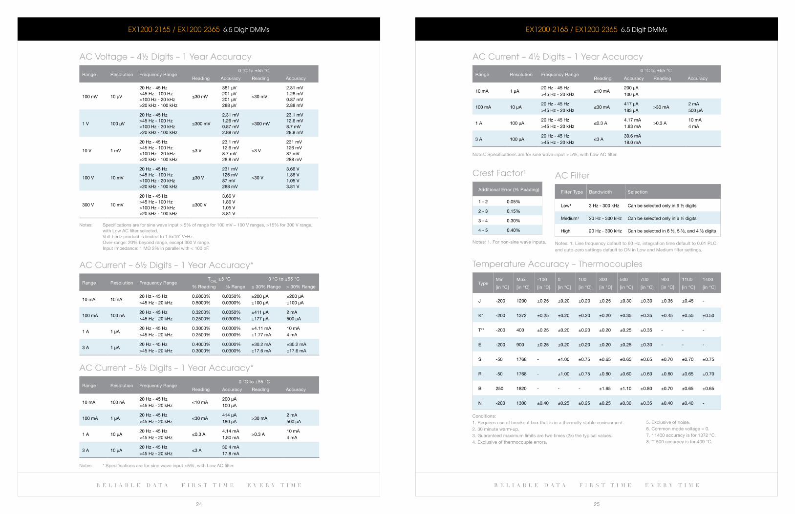
ac Voltage – 4½ Digits – 1 Year accuracy
range resolution frequency range0 °C to ±55 °C
reading accuracy reading accuracy
100 mV 10 μV
20 Hz - 45 Hz>45 Hz - 100 Hz>100 Hz - 20 kHz>20 kHz - 100 kHz
≤30 mV
381 μV201 μV201 μV288 μV
>30 mV
2.31 mV1.26 mV0.87 mV2.88 mV
1 V 100 μV
20 Hz - 45 Hz>45 Hz - 100 Hz>100 Hz - 20 kHz>20 kHz - 100 kHz
≤300 mV
2.31 mV1.26 mV0.87 mV2.88 mV
>300 mV
23.1 mV12.6 mV8.7 mV28.8 mV
10 V 1 mV
20 Hz - 45 Hz>45 Hz - 100 Hz>100 Hz - 20 kHz>20 kHz - 100 kHz
≤3 V
23.1 mV12.6 mV8.7 mV28.8 mV
>3 V
231 mV126 mV87 mV288 mV
100 V 10 mV
20 Hz - 45 Hz>45 Hz - 100 Hz>100 Hz - 20 kHz>20 kHz - 100 kHz
≤30 V
231 mV126 mV87 mV288 mV
>30 V
3.66 V1.86 V1.05 V3.81 V
300 V 10 mV
20 Hz - 45 Hz>45 Hz - 100 Hz>100 Hz - 20 kHz>20 kHz - 100 kHz
≤300 V
3.66 V1.86 V1.05 V3.81 V
notes: specifications are for sine wave input > 5% of range for 100 mV – 100 V ranges, >15% for 300 V range, with low aC filter selected. Volt-hertz product is limited to 1.5x10⁷ V•Hz. Over-range: 20% beyond range, except 300 V range. input impedance: 1 MΩ 2% in parallel with < 100 pf.
ac current – 6½ Digits – 1 Year accuracy*
range resolution frequency rangeT
Cal ±5 °C
% reading % range
0 °C to ±55 °C
≤ 30% range > 30% range
10 ma 10 na20 Hz - 45 Hz >45 Hz - 20 kHz
0.6000% 0.5000%
0.0350% 0.0300%
±200 μa±100 μa
±200 μa±100 μa
100 ma 100 na20 Hz - 45 Hz >45 Hz - 20 kHz
0.3200% 0.2500%
0.0350% 0.0300%
±411 μa ±177 μa
2 ma500 μa
1 a 1 μa20 Hz - 45 Hz >45 Hz - 20 kHz
0.3000% 0.2500%
0.0300% 0.0300%
±4.11 ma ±1.77 ma
10 ma4 ma
3 a 1 μa20 Hz - 45 Hz >45 Hz - 20 kHz
0.4000% 0.3000%
0.0300% 0.0300%
±30.2 ma ±17.6 ma
±30.2 ma ±17.6 ma
ac current – 5½ Digits – 1 Year accuracy*
range resolution frequency range0 °C to ±55 °C
reading accuracy reading accuracy
10 ma 100 na20 Hz - 45 Hz >45 Hz - 20 kHz
≤10 ma200 μa100 μa
100 ma 1 μa20 Hz - 45 Hz >45 Hz - 20 kHz
≤30 ma414 μa180 μa
>30 ma2 ma500 μa
1 a 10 μa20 Hz - 45 Hz >45 Hz - 20 kHz
≤0.3 a4.14 ma1.80 ma
>0.3 a10 ma4 ma
3 a 10 μa20 Hz - 45 Hz >45 Hz - 20 kHz
≤3 a30.4 ma17.8 ma
notes: * specifications are for sine wave input >5%, with low aC filter.
eX1200-2165 / eX1200-2365 6.5 Digit DMMs
ac current – 4½ Digits – 1 Year accuracy
range resolution frequency range0 °C to ±55 °C
reading accuracy reading accuracy
10 ma 1 μa20 Hz - 45 Hz >45 Hz - 20 kHz
≤10 ma200 μa100 μa
100 ma 10 μa20 Hz - 45 Hz >45 Hz - 20 kHz
≤30 ma417 μa183 μa
>30 ma2 ma500 μa
1 a 100 μa20 Hz - 45 Hz >45 Hz - 20 kHz
≤0.3 a4.17 ma1.83 ma
>0.3 a10 ma4 ma
3 a 100 μa20 Hz - 45 Hz >45 Hz - 20 kHz
≤3 a30.6 ma18.0 ma
notes: specifications are for sine wave input > 5%, with low aC filter.
crest Factor¹
additional error (% reading)
1 - 2 0.05%
2 - 3 0.15%
3 - 4 0.30%
4 - 5 0.40%
notes: 1. for non-sine wave inputs.
Temperature accuracy – Thermocouples
TypeMin
[in °C]
Max
[in °C]
-100
[in °C]
0
[in °C]
100
[in °C]
300
[in °C]
500
[in °C]
700
[in °C]
900
[in °C]
1100
[in °C]
1400
[in °C]
J -200 1200 ±0.25 ±0.20 ±0.20 ±0.25 ±0.30 ±0.30 ±0.35 ±0.45 -
k* -200 1372 ±0.25 ±0.20 ±0.20 ±0.20 ±0.35 ±0.35 ±0.45 ±0.55 ±0.50
T** -200 400 ±0.25 ±0.20 ±0.20 ±0.20 ±0.25 ±0.35 - - -
e -200 900 ±0.25 ±0.20 ±0.20 ±0.20 ±0.25 ±0.30 - - -
s -50 1768 - ±1.00 ±0.75 ±0.65 ±0.65 ±0.65 ±0.70 ±0.70 ±0.75
r -50 1768 - ±1.00 ±0.75 ±0.60 ±0.60 ±0.60 ±0.60 ±0.65 ±0.70
b 250 1820 - - - ±1.65 ±1.10 ±0.80 ±0.70 ±0.65 ±0.65
n -200 1300 ±0.40 ±0.25 ±0.25 ±0.25 ±0.30 ±0.35 ±0.40 ±0.40 -
Conditions: 1. requires use of breakout box that is in a thermally stable environment. 2. 30 minute warm-up. 3. guaranteed maximum limits are two times (2x) the typical values. 4. exclusive of thermocouple errors.
ac Filter
filter Type bandwidth selection
low¹ 3 Hz - 300 kHz Can be selected only in 6 ½ digits
Medium¹ 20 Hz - 300 kHz Can be selected only in 6 ½ digits
High 20 Hz - 300 kHz Can be selected in 6 ½, 5 ½, and 4 ½ digits
notes: 1. line frequency default to 60 Hz, integration time default to 0.01 PlC, and auto-zero settings default to On in low and Medium filter settings.
5. exclusive of noise. 6. Common mode voltage = 0. 7. * 1400 accuracy is for 1372 °C.8. ** 500 accuracy is for 400 °C.
w w w . v t i i n s t r u m e n t s . c o m
D a T a S H e e T
r e l i a b l e d a t a f i r s t t i m e e v e r y t i m e
27
r e l i a b l e d a t a f i r s t t i m e e v e r y t i m e
26
eX1200-2165 / eX1200-2365 6.5 Digit DMMs
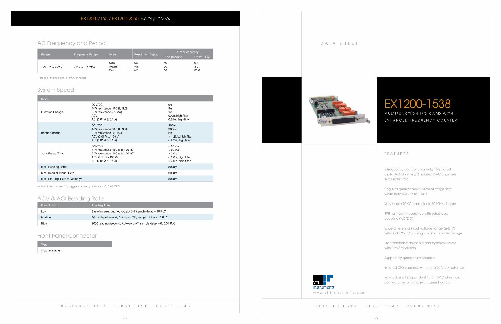
ac Frequency and Period¹
range frequency range Mode resolution Digits1 year accuracy
PPM reading Offset PPM
100 mV to 300 V 3 Hz to 1.5 MHzslowMediumfast
6½5½4½
606060
0.33.030.0
notes: 1. input signal > 10% of range.
System Speed
event
function Change
DCV/DCi4-W resistance (100 Ω, 1kΩ)2-W resistance (<1 MΩ)aCVaCi (0.01 a & 0.1 a)
9/s9/s1/s0.4/s, high filter0.25/s, high filter
range Change
DCV/DCi4-W resistance (100 Ω, 1kΩ)2-W resistance (<1 MΩ)aCV (0.01 V to 100 V)aCi (0.01 a & 0.1 a)
300/s300/s2/s< 1.25/s, high filter< 0.2/s, high filter
auto-range Time
DCV/DCi4-W resistance (100 Ω to 100 kΩ)2-W resistance (100 Ω to 100 kΩ)aCV (0.1 V to 100 V)aCi (0.01 a & 0.1 a)
< 30 ms< 60 ms< 3.0 s< 2.0 s, high filter< 4.0 s, high filter
Max. reading rate¹ 2000/s
Max. internal Trigger rate¹ 2000/s
Max. ext. Trig. rate to Memory¹ 2000/s
notes: 1. auto-zero off, trigger and sample delay = 0, 0.01 PlC.
acV & acI Reading Ratefilter setting reading rate
low 3 readings/second; auto-zero On, sample delay = 10 PlC
Medium 20 readings/second; auto-zero On, sample delay = 10 PlC
High 2000 readings/second; auto-zero off, sample delay = 0, 0.01 PlC
Front Panel connector
Type
5 banana jacks
F e a T U R e S
8frequencycounterchannels,16isolated
digital I/O channels, 2 isolated Dac channels
in a single card
Single frequency measurement range that
works from 0.05 Hz to 1 MHz
Very stable TcXO base clock, 50 MHz ±1 ppm
195 kΩ Input impedance with selectable
coupling (ac/Dc)
Widedifferentialinputvoltagerange(±48V)
with up to 250 V working common mode voltage
Programmable threshold and hysteresis levels
with 1 mV resolution
Support for quadrature encoder
Isolated DIO channels with up to 60 V compliance
Isolated and independent 16-bit Dac channels,
configurable for voltage or current output
EX1200-1538M U l T I F U N c T I O N I / O c a R D w I T H
e N H a N c e D F R e q U e N c Y c O U N T e R
r e l i a b l e d a t a f i r s t t i m e e v e r y t i m e r e l i a b l e d a t a f i r s t t i m e e v e r y t i m e
28 29
EX1200-1538 Multifunction I/O card with enhanced Frequency counter
OVERVIEWTheEX1200-1538isahigh-performancemultifunctioncardthatprovides8-channels
of independent 32-bit counters, 16 channels of isolated digital I/O, and 2 channels
of isolated analog output (Dac) on a single card. The wide range of measurement
functions make this card suitable for both electronic functional test (eFT), as well as
precisiondataacquisitionapplications.CombiningtheEX1200-1538withtheDMM
and switch capabilities allows for a complete measurement, control, and distribution
system in a small 1U rack space.
The electronic counter utilizes a 50 MHz high-stability (1 ppm), TcXO base clock
oscillator along with a 32-bit counter to measure time domain and frequency domain
parameters of repetitive and non-repetitive waveforms. It uses a reciprocal counting
method to achieve a wide frequency measurement range spanning from 0.05 Hz to
1 MHz while ensuring high resolution and accuracy even if the input signals are low
frequency and not synchronized to the aperture window.
Counterchannelsacceptbothanaloganddigitalinputsrangingfrom±48Vof
true differential voltages which makes it suitable to use with almost any real world
signal without the need for external signal conditioning. Programmable hysteresis
and threshold levels over the entire input voltage range can help to extract the
fundamental frequency from the noisiest analog input signals.
electronic counter channels can directly measure the RPM from tooth wheel and
othertypesofsensors.TheEX1200-1538’suniquefunctionalitypreventsthefrequency
bumps caused by missing/extra tooth used for marking the reference. counter
channels can measure position and speed from quadrature encoder signal pairs,
including index channel (a,b and z).
EX1200-1538 Multifunction I/O card with enhanced Frequency counter
TheonboardmemoryofEX1200-1538canstoreupto256,000measurementreadingsand
supports the unified eX1200 triggering system. This makes the data samples time stamped in
theIEEE1588formatforeasycorrelationwithotherdatafromothersystems.Measurements
can also be paced at a constant rate so that time differential parameters, like acceleration,
can be calculated.
TheEX1200-1538isolateddigitalI/Ochannelscanbeconfiguredasinputoroutputonaper
channel basis. each channel is isolated from each other and can accept voltages from 2.5
V to 60 V. The output channels use solid-state switches that work in any polarity. Setting the
output logic levels and reading the input logic states are fully controlled through software.
Dac isolated analog output channels are independently configurable as either constant
voltage or current mode. The output range is fixed (±10 V in voltage mode and ±20 ma in
current mode) and the output levels are programmable with 16-bit resolution. both channels
are isolated from each other and fully protected, providing the capability to be connected
in series or parallel for an even wider output range.
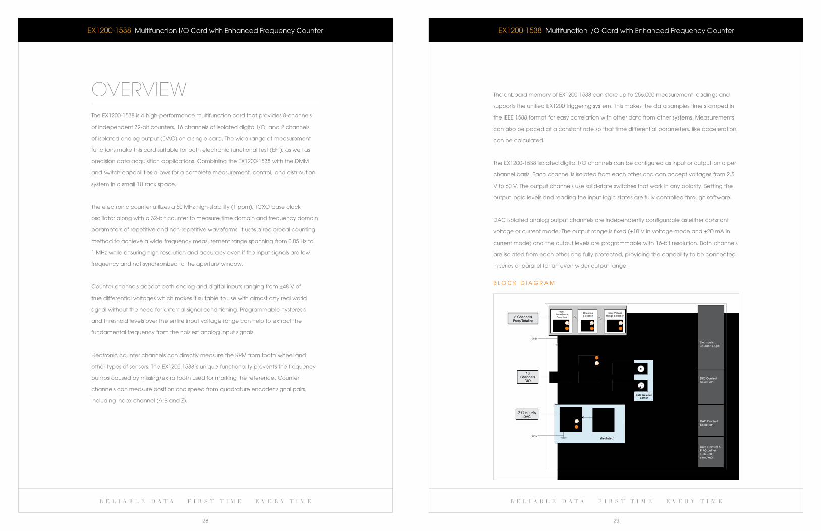
8 ChannelsFreq/Totalize
2 ChannelsDAC
16Channels
DIO
InputImpedanceSelection
High VoltageTransient Direction Control
Digital Input
TCXO(Reference Oscillator - 50 MHz)
Digital Output
Opto Isolator(When Input)
Solid-state
Opto Isolation Barrier
Protection
Output Amplifier
Analog OutputLevel Control(16-bit DAC)
CouplingRange Selection
Input VoltageSelection
ElectronicCounter Logic
DIO ControlSelection
(Isolated)
DAC ControlSelection
Data Control &FIFO buffer(256,000 samples)
(When Output)Switch
Mode Selection
b l O c k D I a G R a M
r e l i a b l e d a t a f i r s t t i m e e v e r y t i m e r e l i a b l e d a t a f i r s t t i m e e v e r y t i m e
30 31
Frequency/counter InputsnUMber Of CHannels 8 (analog/digital)
DigiTal inPUT signal range TTl
analOg inPUT signal range ±48 V (differential)
sensiTiViTy ±500 mV
THresHOlD anD HysTeresis Programmable, 1 mV step
inPUT iMPeDanCe 195 kΩ
inPUT COUPling aC/DC
COMMOn MODe inPUT 250 V peak
signal freqUenCy range 0.05 Hz – 1 MHz in DC coupling mode
3 Hz – 1 MHz aC in coupling mode
Main TiMe base ClOCk 50 MHz (TCXO)
TiMe base ClOCk sTabiliTy ±1 ppm
COUnTer TyPe 32-bit, reciprocal counting type
MaXiMUiM TOTalize TiCk COUnT 4,294,967,295
MiniMUM DeTeCTable PUlse 50 ns on digital channels
600 ns on analog channels
rPM MeasUreMenT range 3 rPM (min) to 90,000 rPM (max) – single range
saMPle DaTa COrrelaTiOn ieee 1588 time stamp
OnbOarD MeMOry 256,000 readings
real-TiMe DaTa OPeraTiOns Time based and pulse count based averaging (256 sample depth)
aVeraging MeTHODs Moving average and simple average
aPerTUre TiMe WinDOW 1 ms to 30 s (1 ms programming step)
MaXiMUM DaTa
sampling speed 1,000,000 samples/s (into on-board buffer)
Triggering software, immediate, eX1200-based lXi triggers
qUaDraTUre MeasUreMenT Two channels to be paired for each encoder input
Digital Input/OutputnUMber Of CHannels 16 channels
DiO inPUT signal leVel
logical High 2.5 V to 60 V
logical low < 2.5 V
DiO isOlaTiOn Channel–to-channel, optical isolation
DiO OUTPUT signals Optically isolated solid-state switch
OUTPUT signal COMPaTibiliTy 50 ma sink/source, up to 60 V (aC/DC)
UPDaTe COnTrOl software paced
EX1200-1538 Multifunction I/O card with enhanced electronic counter
General Specifications
Dac OutputsnUMber Of CHannels 2 channel
OUTPUT TyPe Constant voltage or constant current
OUTPUT MODe static Mode or Dynamic mode (frequency to voltage/current)
VOlTage MODe range ±10 V (bipolar), can supply up to 20 ma per channel
CUrrenT MODe range ±20 ma (bipolar), can drive up to 250 Ω load
OUTPUT resOlUTiOn 16-bit
isOlaTiOn Channel-to-channel, galvanic
PrOTeCTiOn Open and short circuit for continuous duration of time
COnneCTOr TyPe 104-pin HD D-sub
EX1200-1538 Multifunction I/O card with enhanced electronic counter
Ordering InformationeX1200-1538
lOOse MaTing COnneCTiViTy aCCessOries anD TOOls
27-0389-104
27-0390-104
70-0297-001
Pre-asseMbleD, UnTerMinaTeD Wiring Harnesses
70-0363-501
TerMinal blOCks
70-0367-011
Multifunction i/O card with 8 counter, 16 DiO, and 2 DaC channels
104-pin HD D-sub mating connector with hood and pins, fixed contacts
(no crimp tool required)
104-pin HD D-sub mating connector, backshell and pins, crimp style
Crimp tooling, includes handle and positioner, 22 aWg
104p HD D-sub mating connector and backshell, with 3 ft unterminated 22 aWg wire
Terminal block with mating cable assembly
r e l i a b l e d a t a f i r s t t i m e e v e r y t i m e
33
w w w . v t i i n s t r u m e n t s . c o m
D a T a S H e e T
r e l i a b l e d a t a f i r s t t i m e e v e r y t i m e
32
F e a T U R e S
large switching capacity in a small footprint
Switch up to 16 a current - highest in its class
High breakdown voltage (1,000 V rms between
open contacts)
Ideal for switching ac or Dc power supplies
and current sources
Fail-safe interrupt inputs that can detect a fault condition
automatically open up relays to their default state
combine with other eX1200 switch modules to form
a switching subsystem
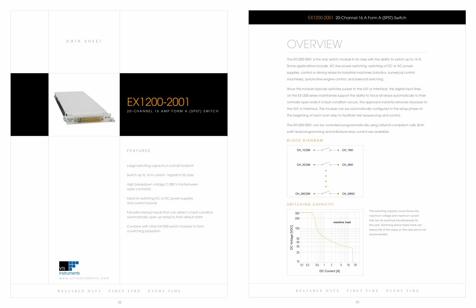
eX1200-20012 0 - c H a N N e l 1 6 a M P F O R M a ( S P S T ) S w I T c H
eX1200-2001 20-channel 16 a Form a (SPST) Switch
OVERVIEWThe eX1200-2001 is the only switch module in its class with the ability to switch up to 16 a.
Some applications include: ac line power switching, switching of Dc or ac power
supplies, control or driving relays for industrial machines (robotics, numerical control
machines), automotive engine control, and solenoid switching.
Since this module typically switches power to the UUT or interface, the digital input lines
on the eX1200 series mainframes support the ability to force all relays automatically to their
normally open state if a fault condition occurs. This approach instantly removes all power to
the UUT or interface. This module can be automatically configured in the setup phase at
the beginning of each scan step to facilitate test sequencing and control.
The eX1200-2001 can be controlled programmatically using IviSwtch-compliant calls. both
path level programming and individual relay control are available.
CH_1COM CH_1NO
CH_2COM CH_2NO
CH_20COM CH_20NO
b l O c k D I a G R a M
DC
Vol
tage
[VD
C]
DC Current [A]
resistive load
S w I T c H I N G c a P a c I T Y
The switching capacity curve shows the
maximum voltage and maximum current
that can be switched simultaneously by
the card. switching above these limits can
reduce life of the relays on the card and is not
recommended.

w w w . v t i i n s t r u m e n t s . c o m
D a T a S H e e T
r e l i a b l e d a t a f i r s t t i m e e v e r y t i m e
35
r e l i a b l e d a t a f i r s t t i m e e v e r y t i m e
34
CHannel COUnT 20 sPsT
MaXiMUM sWiTCHing VOlTage 250 V aC rms, 300 V DC
MaXiMUM sWiTCHing CUrrenT 16 a
MaXiMUM sWiTCHing POWer 480 W DC, 4000 Va per channel
raTeD sWiTCH OPeraTiOns
Mechanical 1 x 10⁷
electrical 1 x 10⁵ at full load
sWiTCHing TiMe < 10 ms
PaTH resisTanCe < 100 mΩ
insUlaTiOn resisTanCe > 1 X 10⁹ Ω
MaXiMUM THerMal OffseT < 50 μVPer CHannel (Hi-lO)
CaPaCiTanCe
Open channel < 20 pf
Channel-mainframe < 75 pf
banDWiDTH (-3 db) 40 MHz (typical)
inserTiOn lOss (TyPiCal)
100 kHz < 0.2 db
1 MHz < 0.5 db
10 MHz < 1.0 db
CrOssTalk (TyPiCal)
100 kHz < -50 db
1 MHz < -35 db
10 MHz < -20 db
COnneCTOr TyPe 41-pin
eX1200-2001 20-channel 16 a Form a (SPST) Switch
General Specifications
Ordering Information
eX1200-2001
aCCessOries anD TOOls
70-0190-001
27-0087-041
27-0087-000
46-0012-000
46-0014-000
46-0015-000
70-0363-506
20-channel, 16 amp form a (sPsT) switch
Connector kit (includes 1 each connector and backshell plus 44 pins)
Connector, power, female with backshell, insulated, 41 PlC
Contact, female, crimp, power connector, 14 - 16 ga (Order qty: 41 per board)
Crimp tool and turret head
Tool, contact insertion, size 16 contact, aMP M series
Tool, pin extractor, power/coaxial
41-pin, 16ga, unterminated cable assembly, 3 ft
F e a T U R e S
large switching capacity in a small footprint
Switch up to 16 a current - highest in its class
High breakdown voltage (1,000 V rms between
open contacts)
Ideal for switching ac or dc power supplies
and current sources
Fail-safe interrupt inputs that can detect
a fault condition automatically open up relays
to their default state
combine with other eX1200 switch modules
to form a switching subsystem
eX1200-20021 2 - c H a N N e l 1 6 a M P F O R M c ( S P D T ) S w I T c H
r e l i a b l e d a t a f i r s t t i m e e v e r y t i m e r e l i a b l e d a t a f i r s t t i m e e v e r y t i m e
36 37
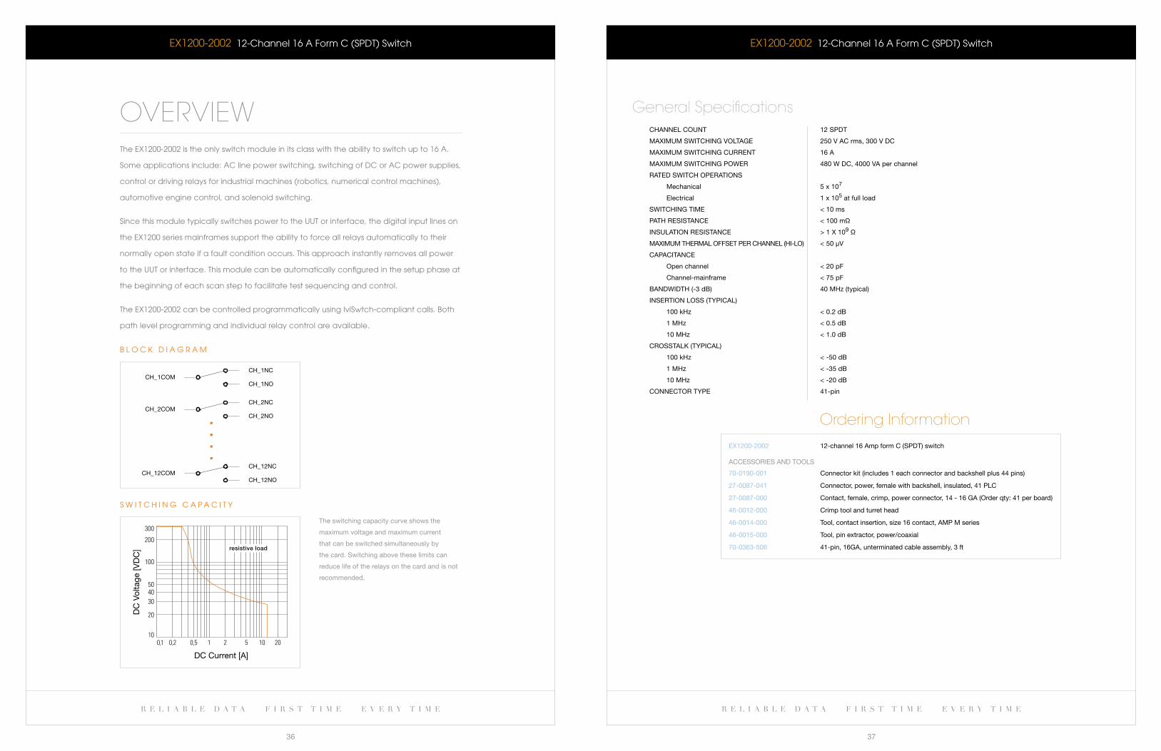
eX1200-2002 12-channel 16 a Form c (SPDT) Switch
OVERVIEWThe eX1200-2002 is the only switch module in its class with the ability to switch up to 16 a.
Some applications include: ac line power switching, switching of Dc or ac power supplies,
control or driving relays for industrial machines (robotics, numerical control machines),
automotive engine control, and solenoid switching.
Since this module typically switches power to the UUT or interface, the digital input lines on
the eX1200 series mainframes support the ability to force all relays automatically to their
normally open state if a fault condition occurs. This approach instantly removes all power
to the UUT or interface. This module can be automatically configured in the setup phase at
the beginning of each scan step to facilitate test sequencing and control.
The eX1200-2002 can be controlled programmatically using IviSwtch-compliant calls. both
path level programming and individual relay control are available.
CH_1NOCH_1COM
CH_1NC
CH_2NOCH_2COM
CH_2NC
CH_12NOCH_12COM
CH_12NC
b l O c k D I a G R a M
DC
Vol
tage
[VD
C]
DC Current [A]
resistive load
S w I T c H I N G c a P a c I T Y
The switching capacity curve shows the
maximum voltage and maximum current
that can be switched simultaneously by
the card. switching above these limits can
reduce life of the relays on the card and is not
recommended.
eX1200-2002 12-channel 16 a Form c (SPDT) Switch
CHannel COUnT 12 sPDT
MaXiMUM sWiTCHing VOlTage 250 V aC rms, 300 V DC
MaXiMUM sWiTCHing CUrrenT 16 a
MaXiMUM sWiTCHing POWer 480 W DC, 4000 Va per channel
raTeD sWiTCH OPeraTiOns
Mechanical 5 x 10⁷
electrical 1 x 10⁵ at full load
sWiTCHing TiMe < 10 ms
PaTH resisTanCe < 100 mΩ
insUlaTiOn resisTanCe > 1 X 10⁹ Ω
MaXiMUM THerMal OffseT Per CHannel (Hi-lO) < 50 μV
CaPaCiTanCe
Open channel < 20 pf
Channel-mainframe < 75 pf
banDWiDTH (-3 db) 40 MHz (typical)
inserTiOn lOss (TyPiCal)
100 kHz < 0.2 db
1 MHz < 0.5 db
10 MHz < 1.0 db
CrOssTalk (TyPiCal)
100 kHz < -50 db
1 MHz < -35 db
10 MHz < -20 db
COnneCTOr TyPe 41-pin
General Specifications
eX1200-2002 12-channel 16 amp form C (sPDT) switch
Ordering Information
70-0190-001
27-0087-041
27-0087-000
46-0012-000
46-0014-000
46-0015-000
70-0363-506
Connector kit (includes 1 each connector and backshell plus 44 pins)
Connector, power, female with backshell, insulated, 41 PlC
Contact, female, crimp, power connector, 14 - 16 ga (Order qty: 41 per board)
Crimp tool and turret head
Tool, contact insertion, size 16 contact, aMP M series
Tool, pin extractor, power/coaxial
41-pin, 16ga, unterminated cable assembly, 3 ft
aCCessOries anD TOOls
r e l i a b l e d a t a f i r s t t i m e e v e r y t i m e
39
w w w . v t i i n s t r u m e n t s . c o m
D a T a S H e e T
r e l i a b l e d a t a f i r s t t i m e e v e r y t i m e
38
F e a T U R e S
Highest density module in its class for ability to
switch signals up to 1000 VDc (up to 144 two-wire
channels in a 1U footprint)
built-in configuration relays expand the individual
building blocks
Ideal for hipot, cable breakdown, source measure
unit, and power supply switching
extensive signal shielding employed on-board for
excellent signal fidelity
Fail-safe interrupts can detect fault condition and
automatically open up relays to a default state
eX1200-2007a4 8 - C H A N N E L 1 0 0 0 V M U L T I P L E X E R
eX1200-2007a 48-Channel1000VMultiplexer
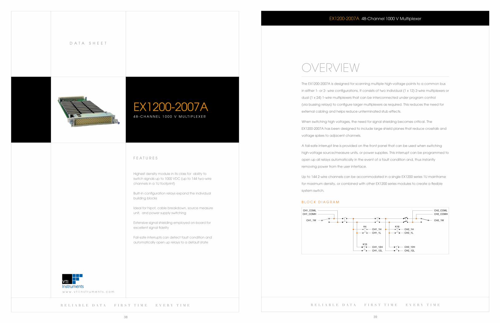
OVERVIEWThe eX1200-2007a is designed for scanning multiple high-voltage points to a common bus
in either 1- or 2- wire configurations. It consists of two individual (1 x 12) 2-wire multiplexers or
dual (1 x 24) 1-wire multiplexers that can be interconnected under program control
(via bussing relays) to configure larger multiplexers as required. This reduces the need for
external cabling and helps reduce unterminated stub effects.
when switching high voltages, the need for signal shielding becomes critical. The
eX1200-2007a has been designed to include large shield planes that reduce crosstalk and
voltage spikes to adjacent channels.
a fail-safe interrupt line is provided on the front panel that can be used when switching
high-voltage source/measure units, or power supplies. This interrupt can be programmed to
open up all relays automatically in the event of a fault condition and, thus instantly
removing power from the user interface.
Up to 144 2-wire channels can be accommodated in a single eX1200 series 1U mainframe
for maximum density, or combined with other eX1200 series modules to create a flexible
system switch.
CH1_COML
CH1_COMH
CH1_12L
K4CH2_1H
CH2_1L
K16CH1_1H
CH1_1L
CH1_12HK15
CH2_12H
CH2_12L
CH1_1W
CH2_COML
CH2_COMH
CH2_1W
b l O c k D I a G R a M
w w w . v t i i n s t r u m e n t s . c o m
D a T a S H e e T
r e l i a b l e d a t a f i r s t t i m e e v e r y t i m e
41
r e l i a b l e d a t a f i r s t t i m e e v e r y t i m e
40
eX1200-2007a 48-Channel1000VMultiplexer
CHannel COUnT (1 x 24) 2-wire, dual (1 x 12) 2-wire, or dual (1 x 24) 1-wire
relay TyPe reed
MaXiMUM sWiTCHing VOlTage 1000 V DC / 700 V aC rms
MaXiMUM sWiTCHing CUrrenT 1 a
MaXiMUM Carrying CUrrenT 2 a
MaXiMUM sWiTCHing POWer 25 W (resistive load)
raTeD sWiTCH OPeraTiOns
Mechanical 5 x 10⁸
electrical 1 x 10⁶ (full load)
sWiTCHing TiMe < 1 ms
PaTH resisTanCe < 1 Ω
insUlaTiOn resisTanCe > 1 X 10⁷ Ω
banDWiDTH (-3 db) 60 MHz (typical)
COnneCTOr TyPe 160-pin Din with interleaved connections
notes:
The eX1200-2007a is intended to be used as a multiplexer only and not as a splitter (i.e.
split a single input signal into multiple paths). Use of the eX1200-2007a as a splitter may
cause damage to its circuitry.
General Specifications
Ordering InformationeX1200-2007a 48-channel 1000 V multiplexer
70-0363-504
70-0363-503
52-0109-000
27-0088-160
46-0010-000
46-0011-000
70-0363-507
strain relief bracket (includes connector, recommended accessory)
strain relief bracket kit (without connector)
Crimp pin (includes 100 crimp pins)
Mating connector (one per board)
Crimp tool (Din)
extraction tool (Din)
160-pin to 80-pin, unterminated cable assembly, 3 ft
aCCessOries anD TOOls
F e a T U R e S
High-density, high-voltage multiplexer/scanner
(1x180in1Usize)
Ideal for hipot, cable breakdown, source-
measure-unit, and power supply switching
extensive signal shielding employed on Pcbs
for excellent signal fidelity
break-before-make (bbM) and make-before-break
(Mbb) accomplished in hardware, considerably
improving scanning time
Fail-safe interrupts can detect fault condition and
automatically open up relays to a default state
EX1200-2008H3 0 - c H a N N e l 3 ( 1 X 1 0 )
H I G H - V O l T a G e M U l T I P l e X e R
r e l i a b l e d a t a f i r s t t i m e e v e r y t i m e r e l i a b l e d a t a f i r s t t i m e e v e r y t i m e
42 43
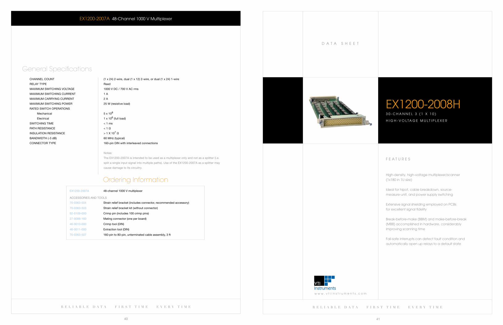
EX1200-2008H 30-channel 3 (1 x 10) High-Voltage Multiplexer
OVERVIEWTheEX1200-2008Hisahigh-voltagemultiplexermoduledesignedforelectricalsafety
testing, insulation testing kind of applications whose voltage levels exceed standard
300Vlevel.EX1200-2008Hisdesignedtoswitchvoltagesupto1000V,atpowerlevelsup
to25VA.Eachcardcontainsthreebanksof10x1multiplexers.TheEX1200-2008Hcanbe
mixed and matched with other eX1200 series plug-in modules in a single mainframe to
construct a flexible mixed-signal switching subsystem.
TheEX1200-2008Hhasbeendesignedforapplicationsrequiringhigh-voltagesignal
switching. when switching high voltages, the need for signal shielding becomes critical. This
module has been designed to include large shield planes to reduce crosstalk and voltage
spikes to adjacent channels.
For aTe applications, such as switching high-voltage source measure units or power
supplies, a fail-safe interrupt line (TTl-logic) is provided on the front panel. a change in state
on this input pin can be used to create a fault condition and force all relays to their open
state. This approach provides an additional layer of safety in the event that an adapter is
removed by a technician while voltage is still present at the interface panel.
CH1_1CH1_COM
CH1_2
CH1_9
CH1_10
CH2_1
CH2_2
CH2_9
CH2_10
CH2_COM CH3_1CH3_COM
CH3_2
CH3_9
CH3_10
K21
b l O c k D I a G R a M
EX1200-2008H 30-channel 3 (1 x 10) High-Voltage Multiplexer
relay TyPe reed
COnfigUraTiOn 3 banks of 1 x 10 (single wire) multiplexer
MaXiMUM sWiTCHing VOlTage 1000 V DC / 700 V aC
MaXiMUM sWiTCHing CUrrenT 1 a
MaXiMUM Carrying CUrrenT 2 a
MaXiMUM sWiTCHing POWer 25 W DC / 25 Va
PaTH resisTanCe < 1 Ω (resistive load)
insUlaTiOn resisTanCe > 1 X 10⁷ Ω
banDWiDTH (-3 db) 60 MHz (typical)
raTeD sWiTCH OPeraTiOns
Mechanical 100 x 106
electrical 1 x 10⁶ at full load
sWiTCHing TiMe < 1 ms
COnneCTOr TyPe 160-pin Din with interleaved connections
General Specifications
Ordering InformationeX1200-2008H Three 1x10 single wire high-voltage multiplexer, 1000 V/25 Va
70-0363-504
70-0363-503
52-0109-000
27-0088-160
46-0010-000
46-0011-000
70-0363-507
strain relief bracket (includes connector, recommended accessory)
strain relief bracket kit (without connector)
Crimp pin (includes 100 crimp pins)
Mating connector (one per board)
Crimp tool (Din)
extraction tool (Din)
160-pin to 80-pin, unterminated cable assembly, 3 ft
aCCessOries anD TOOls
r e l i a b l e d a t a f i r s t t i m e e v e r y t i m e
45
w w w . v t i i n s t r u m e n t s . c o m
D a T a S H e e T
r e l i a b l e d a t a f i r s t t i m e e v e r y t i m e
44
F e a T U R e S
High-density 300 V/2 a multiplexing scanning
(upto384two-wirechannelsin1Ufootprint)
configure as 1-, 2-, or 4-wire multiplexers under
program control
Supports thermocouple, RTD, and thermistor
measurements with optional terminal block
Direct routing to eX1200 series DMM through internal
analog measurement bus simplifies field wiring
On-board scanning greatly reduces overall test
execution time
eX1200-3001DS adds discharge relay to bleed
stray charge for sensitive measurements
eX1200-3001eX1200-3001DS( 8 ) 1 X 8 , 2 - W I R E 3 0 0 V / 2 A M U L T I P L E X E R
eX1200-3001/3001DS (8)1x8,2-Wire300V/2AMultiplexer
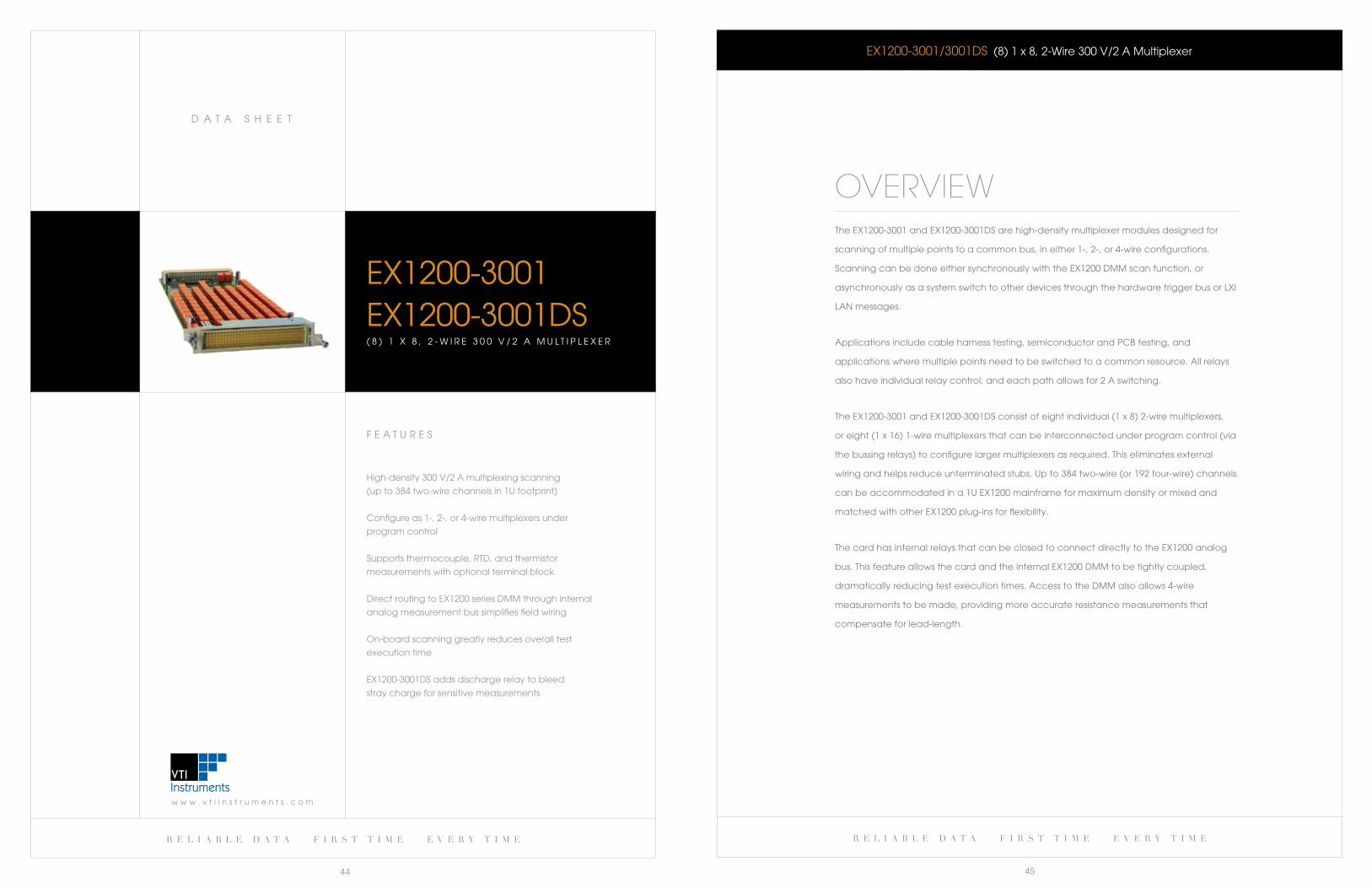
OVERVIEWThe eX1200-3001 and eX1200-3001DS are high-density multiplexer modules designed for
scanning of multiple points to a common bus, in either 1-, 2-, or 4-wire configurations.
Scanning can be done either synchronously with the eX1200 DMM scan function, or
asynchronously as a system switch to other devices through the hardware trigger bus or lXI
laN messages.
applications include cable harness testing, semiconductor and Pcb testing, and
applications where multiple points need to be switched to a common resource. all relays
also have individual relay control, and each path allows for 2 a switching.
TheEX1200-3001andEX1200-3001DSconsistofeightindividual(1x8)2-wiremultiplexers,
or eight (1 x 16) 1-wire multiplexers that can be interconnected under program control (via
the bussing relays) to configure larger multiplexers as required. This eliminates external
wiringandhelpsreduceunterminatedstubs.Upto384two-wire(or192four-wire)channels
can be accommodated in a 1U eX1200 mainframe for maximum density or mixed and
matched with other eX1200 plug-ins for flexibility.
The card has internal relays that can be closed to connect directly to the eX1200 analog
bus. This feature allows the card and the internal eX1200 DMM to be tightly coupled,
dramatically reducing test execution times. access to the DMM also allows 4-wire
measurements to be made, providing more accurate resistance measurements that
compensate for lead-length.
r e l i a b l e d a t a f i r s t t i m e e v e r y t i m e r e l i a b l e d a t a f i r s t t i m e e v e r y t i m e
46 47
eX1200-3001/3001DS (8)1x8,2-Wire300V/2AMultiplexer
CH2_1H
CH2_1L
CH2_2H
CH2_2L
CH2_8H
CH2_8L
CH1_1H
CH1_1L
CH1_2H
CH1_2L
CH1_8H
CH1_8L
CH1_COMH
CH1_COML
NC
CH1_1W
J1
CH2_COMH
CH2_COML
NC
CH2_1W
J2
CH8_COMH
CH8_COML
NC
CH8_1W
J8
CH8_1H
CH8_1L
CH8_2H
CH8_2L
CH8_8H
CH8_8L
Voltage and Resistance Measurements
CH1_COMH (Pin B1)
CH1_COML (Pin B2)
K80
CH5_COMH (Pin B17)
CH5_COML (Pin B18)
K84
DM
M B
us
BPL_HI
BPL_LO
4-Wire Resistance
K96
K97
DM
M B
us
BPL_SHI
BPL_SLO
CH1_COMH (Pin B1)
CH1_COML (Pin B2)
CH5_COMH (Pin B17)
CH5_COML (Pin B18)
CH1_COML (Pin B2)
Current Measurements (2 A Max)
K88
K92
DM
M B
us
BPL_DAMPS
BPL_LO
CH1_COMH (Pin B1)
CH5_COMH (Pin B17)
CH5_COML (Pin B18)
Relays to the EX1200 DMM Backplane
e X 1 2 0 0 - 3 0 0 1 b l O c k D I a G R a M
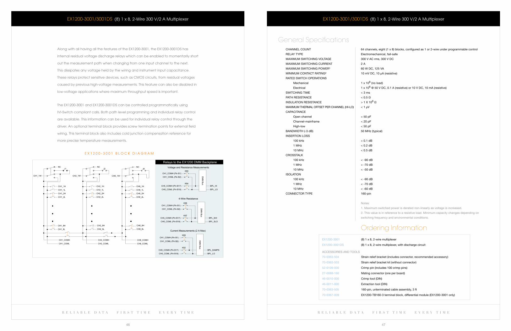
along with all having all the features of the eX1200-3001, the eX1200-3001DS has
internal residual voltage discharge relays which can be enabled to momentarily short
out the measurement path when changing from one input channel to the next.
This dissipates any voltage held by the wiring and instrument input capacitance.
These relays protect sensitive devices, such as cMOS circuits, from residual voltages
caused by previous high-voltage measurements. This feature can also be disabled in
low-voltage applications where maximum throughput speed is important.
The eX1200-3001 and eX1200-3001DS can be controlled programmatically using
IVI-Switch compliant calls. both path level programming and individual relay control
are available. This information can be used for individual relay control through the
driver. an optional terminal block provides screw termination points for external field
wiring. This terminal block also includes cold junction compensation reference for
more precise temperature measurements.
eX1200-3001/3001DS (8)1x8,2-Wire300V/2AMultiplexer
CHannel COUnT 64 channels, eight (1 x 8) blocks, configured as 1 or 2-wire under programmable control
relay TyPe electromechanical, fail-safe
MaXiMUM sWiTCHing VOlTage 300 V aC rms, 300 V DC
MaXiMUM sWiTCHing CUrrenT 2 a
MaXiMUM sWiTCHing POWer¹ 60 W DC, 125 Va
MiniMUM COnTaCT raTing² 10 mV DC, 10 μa (resistive)
raTeD sWiTCH OPeraTiOns
Mechanical 1 x 10⁸ (no load)
electrical 1 x 10⁶ @ 50 V DC, 0.1 a (resistive) or 10 V DC, 10 ma (resistive)
sWiTCHing TiMe < 3 ms
PaTH resisTanCe < 0.5 Ω
insUlaTiOn resisTanCe > 1 X 10⁹ Ω
MaXiMUM THerMal OffseT Per CHannel (Hi-lO) < 1 μV
CaPaCiTanCe
Open channel < 50 pf
Channel-mainframe < 20 pf
High-low < 50 pf
banDWiDTH (-3 db) 50 MHz (typical)
inserTiOn lOss
100 kHz < 0.1 db
1 MHz < 0.2 db
10 MHz < 0.5 db
CrOssTalk
100 kHz < -90 db
1 MHz < -70 db
10 MHz < -50 db
isOlaTiOn
100 kHz < -90 db
1 MHz < -70 db
10 MHz < -60 db
COnneCTOr TyPe 160-pin
notes:
1. Maximum switched power is derated non-linearly as voltage is increased.
2. This value is in reference to a resistive load. Minimum capacity changes depending on
switching frequency and environmental conditions.
General Specifications
Ordering Information
eX1200-3001
eX1200-3001Ds
(8) 1 x 8, 2-wire multiplexer
(8) 1 x 8, 2-wire multiplexer, with discharge circuit
70-0363-504
70-0363-503
52-0109-000
27-0088-160
46-0010-000
46-0011-000
70-0363-505
70-0367-009
strain relief bracket (includes connector, recommended accessory)
strain relief bracket kit (without connector)
Crimp pin (includes 100 crimp pins)
Mating connector (one per board)
Crimp tool (Din)
extraction tool (Din)
160-pin, unterminated cable assembly, 3 ft
eX1200-Tb160-3 terminal block, differential module (eX1200-3001 only)
aCCessOries anD TOOls
r e l i a b l e d a t a f i r s t t i m e e v e r y t i m e
49
w w w . v t i i n s t r u m e n t s . c o m
D a T a S H e e T
r e l i a b l e d a t a f i r s t t i m e e v e r y t i m e
48
F e a T U R e S
High-density 300 V/2 a multiplexing scanning
(upto288two-wirechannelsin1Ufootprint)
High current bank available for current
measurement up to 3a
Two individual (1x24) 2-wire multiplexer banks
programmablycombinabletoforma1x48multiplexer
configure as 2- or 4-wire multiplexers under
program control
Internal capacitive discharge relays keep high
voltages from disturbing sensitive measurement points
Supports thermocouple, RTD, and thermistor
measurements
Optional screw-terminal junction box includes
built-in cold-junction compensation
Direct routing to DMM through internal analog
measurement bus simplifies field wiring
EX1200-30484 8 - C H A N N E L 3 0 0 V / 2 A M U L T I P L E X E R
EX1200-3048 48-Channel300V/2AMultiplexer
OVERVIEWTheEX1200-3048isahigh-densitymultiplexermodulesdesignedforscanningofmultiple
points to a common bus, in either 2- or 4-wire configurations. Scanning can be done either
synchronously with the eX1200 DMM scan function or asynchronously as a system switch to
other devices through the hardware trigger bus or lXI laN messages.
applications include cable harness testing, temperature/voltage monitoring, Pcb testing,
and those in which multiple points need to be switched to a common resource. all relays also
have individual control, and each path allows for hot switching of up to 300 V and 2 a (60 w
Dc max). Two dedicated channels have the capability to directly measure current up to 3 a.
TheEX1200-3048consistsofdual(1x24)2-wiremultiplexerbanks.Eachbankcanbe
interconnected within a module under program control (via bussing relays) to form a 1 x
48multiplexer.TheEX1200analogbuscanbeusedtoconfigurelargermultiplexerswhich
eliminatesexternalwiringandhelpsreduceunterminatedstubeffects.Upto288two-wire
(or 144 four-wire) channels can be accommodated in a single eX1200 full rack mainframe for
maximum density or mixed and matched with other eX1200 plug-ins for flexibility.
Internal residual voltage discharge relays can be enabled to momentarily short out the
measurement path when changing from one input channel to the next. This dissipates any
voltage held by the wiring and instrument input capacitance. These relays protect sensitive
devices, such as cMOS circuits, from residual voltages caused by previous high-voltage
measurements. This feature can also be disabled in low-voltage applications where maximum
throughput speed is important.
an optional terminal block provides screw termination points for external field wiring.
This terminal block also includes cold junction compensation reference for more precise
temperature measurements.
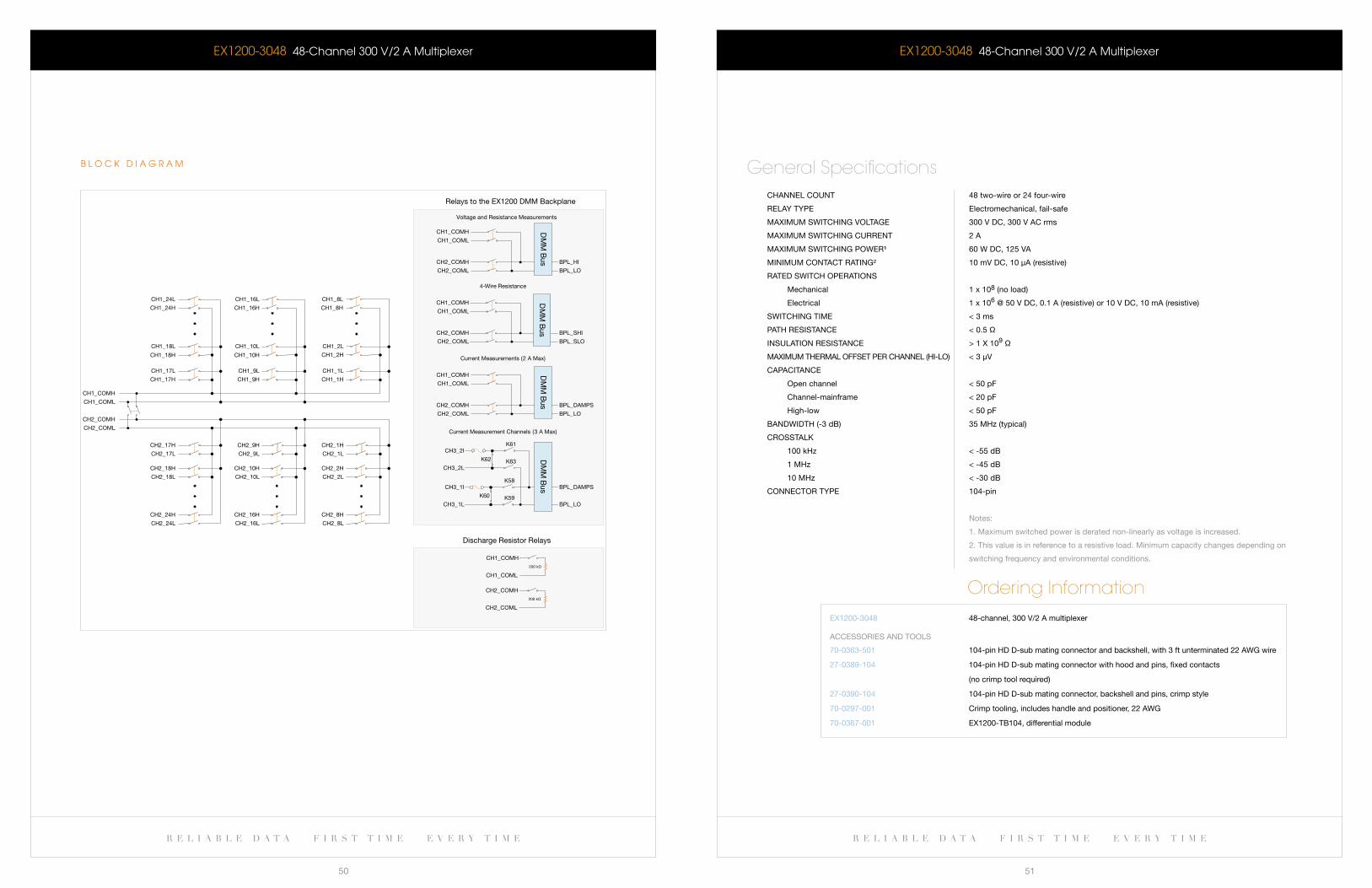
r e l i a b l e d a t a f i r s t t i m e e v e r y t i m e r e l i a b l e d a t a f i r s t t i m e e v e r y t i m e
50 51
Voltage and Resistance Measurements
Relays to the EX1200 DMM Backplane
Discharge Resistor Relays
CH1_COMH
CH1_COML
CH2_COMH
CH2_COML
CH1_16L
CH1_16H CH1_8H
CH1_8L
CH1_24H
CH1_24L
CH1_9L
CH1_9H
CH1_1L
CH1_1HCH1_17H
CH1_17L
CH1_10L
CH1_10H
CH1_2L
CH1_2HCH1_18H
CH1_18L
CH2_16H
CH2_16L
CH2_24H
CH2_24L
CH2_8H
CH2_8L
CH2_10H
CH2_10L
CH2_18H
CH2_18L
CH2_2H
CH2_2L
CH2_9H
CH2_9L
CH2_17H
CH2_17L
CH2_1H
CH2_1L
200 kΩ
200 kΩ
CH1_COMH
CH1_COML
CH2_COMH
CH2_COML
4-Wire Resistance
Current Measurements (2 A Max)
Current Measurement Channels (3 A Max)
CH1_COMH
CH1_COML
CH2_COMH
CH2_COML
DM
M B
us BPL_HI
BPL_LO
CH1_COMH
CH1_COML
CH2_COMH
CH2_COML
DM
M B
us BPL_SHI
BPL_SLO
CH1_COMH
CH1_COML
CH2_COMH
CH2_COML
DM
M B
us BPL_DAMPS
BPL_LO
BPL_LO
BPL_DAMPSCH3_1I
CH3_1L
K60
K58
K59
DM
M B
us
CH3_2I
CH3_2L
K62
K61
K63
b l O c k D I a G R a M
EX1200-3048 48-Channel300V/2AMultiplexer EX1200-3048 48-Channel300V/2AMultiplexer
CHannel COUnT 48 two-wire or 24 four-wire
relay TyPe electromechanical, fail-safe
MaXiMUM sWiTCHing VOlTage 300 V DC, 300 V aC rms
MaXiMUM sWiTCHing CUrrenT 2 a
MaXiMUM sWiTCHing POWer¹ 60 W DC, 125 Va
MiniMUM COnTaCT raTing² 10 mV DC, 10 μa (resistive)
raTeD sWiTCH OPeraTiOns
Mechanical 1 x 10⁸ (no load)
electrical 1 x 10⁶ @ 50 V DC, 0.1 a (resistive) or 10 V DC, 10 ma (resistive)
sWiTCHing TiMe < 3 ms
PaTH resisTanCe < 0.5 Ω
insUlaTiOn resisTanCe > 1 X 10⁹ Ω
MaXiMUM THerMal OffseT Per CHannel (Hi-lO) < 3 μV
CaPaCiTanCe
Open channel < 50 pf
Channel-mainframe < 20 pf
High-low < 50 pf
banDWiDTH (-3 db) 35 MHz (typical)
CrOssTalk
100 kHz < -55 db
1 MHz < -45 db
10 MHz < -30 db
COnneCTOr TyPe 104-pin
notes:
1. Maximum switched power is derated non-linearly as voltage is increased.
2. This value is in reference to a resistive load. Minimum capacity changes depending on
switching frequency and environmental conditions.
General Specifications
Ordering InformationeX1200-3048 48-channel, 300 V/2 a multiplexer
70-0363-501
27-0389-104
27-0390-104
70-0297-001
70-0367-001
104-pin HD D-sub mating connector and backshell, with 3 ft unterminated 22 aWg wire
104-pin HD D-sub mating connector with hood and pins, fixed contacts
(no crimp tool required)
104-pin HD D-sub mating connector, backshell and pins, crimp style
Crimp tooling, includes handle and positioner, 22 aWg
eX1200-Tb104, differential module
aCCessOries anD TOOls

r e l i a b l e d a t a f i r s t t i m e e v e r y t i m e
53
w w w . v t i i n s t r u m e n t s . c o m
D a T a S H e e T
r e l i a b l e d a t a f i r s t t i m e e v e r y t i m e
52
F e a T U R e S
High-densitysolid-statemultiplexer,upto288
2-wire channels per full rack mainframe
On/off switching < 500 μs
Switch up to 250 Vac / 250 VDc, highest for
a solid state switch module in its class
configure as 2- or 4-wire multiplexers
Optically isolated design
Supports thermocouple, RTD, and thermistor
measurements
Optional screw-terminal junction box includes
built-in cold-junction compensation
Direct routing to DMM through internal analog
measurement bus simplifies field wiring
EX1200-3048S4 8 - C H A N N E L F E T M U L T I P L E X E R
EX1200-3048S 48-ChannelFETMultiplexer
OVERVIEWTheEX1200-3048Sisahigh-densityFETmultiplexermoduledesignedforscanningofmultiplepointstoa
common bus in either 2- or 4-wire configurations. Scanning can be done either synchronously with the eX1200
DMM scan function or asynchronously as a system switch to other devices through the hardware trigger bus
or lXI laN messages.
Thesolid-statedesigndeliversmaximumswitchingspeedandnearinfinitelife.Upto288two-wire(or144
four-wire) channels can be accommodated in a single eX1200 full rack mainframe for maximum density or
mixed and matched with other eX1200 plug-ins for flexibility. Typical applications include temperature and
voltage data acquisition and datalogging at up to 1000 scans per second.
TheEX1200-3048Sconsistsofdual(1x24)2-wiremultiplexerbanks.Eachbankcanbeinterconnectedwithin
a module under program control (via bussing relays) and across modules via the eX1200 analog bus to
configure larger multiplexers as required. This eliminates external wiring and helps reduce unterminated stubs.
Internal residual voltage discharge relays can be enabled to momentarily short out the measurement path
when changing from one input channel to the next. This dissipates any voltage held by the wiring and
instrument input capacitance. These relays protect sensitive devices, such as cMOS circuits, from residual
voltages caused by previous high-voltage measurements. This feature can also be disabled in low-voltage
applications where maximum throughput speed is important. an optional terminal block provides screw
termination points for external field wiring. This terminal block also includes cold junction compensation
reference for more precise temperature measurements.
CH1_COMH
CH1_COML
CH2_COMH
CH2_COML
CH1_24H
CH1_9L
CH1_9H
CH1_1L
CH1_1HCH1_17H
CH1_17L
CH1_10L
CH1_10H
CH1_2L
CH1_2HCH1_18H
CH1_18L
CH2_16H
CH2_16L
CH2_24H
CH2_24L
CH2_8H
CH2_8L
CH2_10H
CH2_10L
CH2_18H
CH2_18L
CH2_2H
CH2_2L
CH2_9H
CH2_9L
CH2_17H
CH2_17L
CH2_1H
CH2_1L
CH1_24L CH1_16LCH1_16H
CH1_8LCH1_8H
b l O c k D I a G R a M

w w w . v t i i n s t r u m e n t s . c o m
D a T a S H e e T
r e l i a b l e d a t a f i r s t t i m e e v e r y t i m e
55
r e l i a b l e d a t a f i r s t t i m e e v e r y t i m e
54
EX1200-3048S 48-ChannelFETMultiplexer
CHannel COUnT 48 two-wire or 24 four-wire
relay TyPe Opto-isolated solid-state
MaXiMUM sWiTCHing VOlTage 250 V
MaXiMUM sWiTCHing CUrrenT 0.2 a
MaXiMUM sWiTCHing POWer 6 W / 4.2 Va
raTeD sWiTCH OPeraTiOns Unlimited (solid state relays)
sWiTCHing TiMe < 500 μs
PaTH resisTanCe < 8 Ω
insUlaTiOn resisTanCe > 1 X 10⁹ Ω
MaXiMUM THerMal OffseT Per CHannel (Hi-lO) < 7 μV
CaPaCiTanCe
Open channel < 50 pf
Channel-mainframe < 20 pf
High-low < 50 pf
banDWiDTH (-3 db) > 10 MHz
CrOssTalk (TyPiCal)
100 kHz < -55 db
1 MHz < -45 db
10 MHz < -30 db
isOlaTiOn (TyPiCal)
100 kHz < -55 db
1 MHz < -40 db
10 MHz < -25 db
COnneCTOr TyPe 104-pin
application notes:
solid-state relays are not ideally suited for low-level resistance measurements (< 1 Ω).
The relays have an internal resistance of approximately 13 mV which is significant
under these circumstances. a leakage current is also present in solid-state relays which
varies dramatically with temperature, affecting low-level resistance measurements.
General Specifications
Ordering InformationeX1200-3048s 48-channel 2-wire feT multiplexer
70-0363-501
27-0389-104
27-0390-104
70-0297-001
70-0367-001
104-pin HD D-sub mating connector and backshell, with 3 ft unterminated 22 aWg wire
104-pin HD D-sub mating connector with hood and pins, fixed contacts
(no crimp tool required)
104-pin HD D-sub mating connector, backshell and pins, crimp style
Crimp tooling, includes handle and positioner, 22 aWg
eX1200-Tb104, differential module
aCCessOries anD TOOls
F e a T U R e S
High-density 300 V/2 a multiplexing scanning
(up to 432 two-wire channels in 1U footprint)
Two individual (1x36) 2-wire multiplexer banks
programmably combinable to form a 1x72 multiplexer
configure as 2- or 4-wire multiplexers under
program control
Internal capacitive discharge relays keep high
voltages from disturbing sensitive measurement points
Supports thermocouple, RTD, and thermistor measurements
Optional screw-terminal junction box includes
built-in cold-junction compensation
Direct routing to DMM through internal analog
measurement bus simplifies field wiring
eX1200-30727 2 - c H a N N e l 2 - w I R e 3 0 0 V / 2 a M U l T I P l e X e R
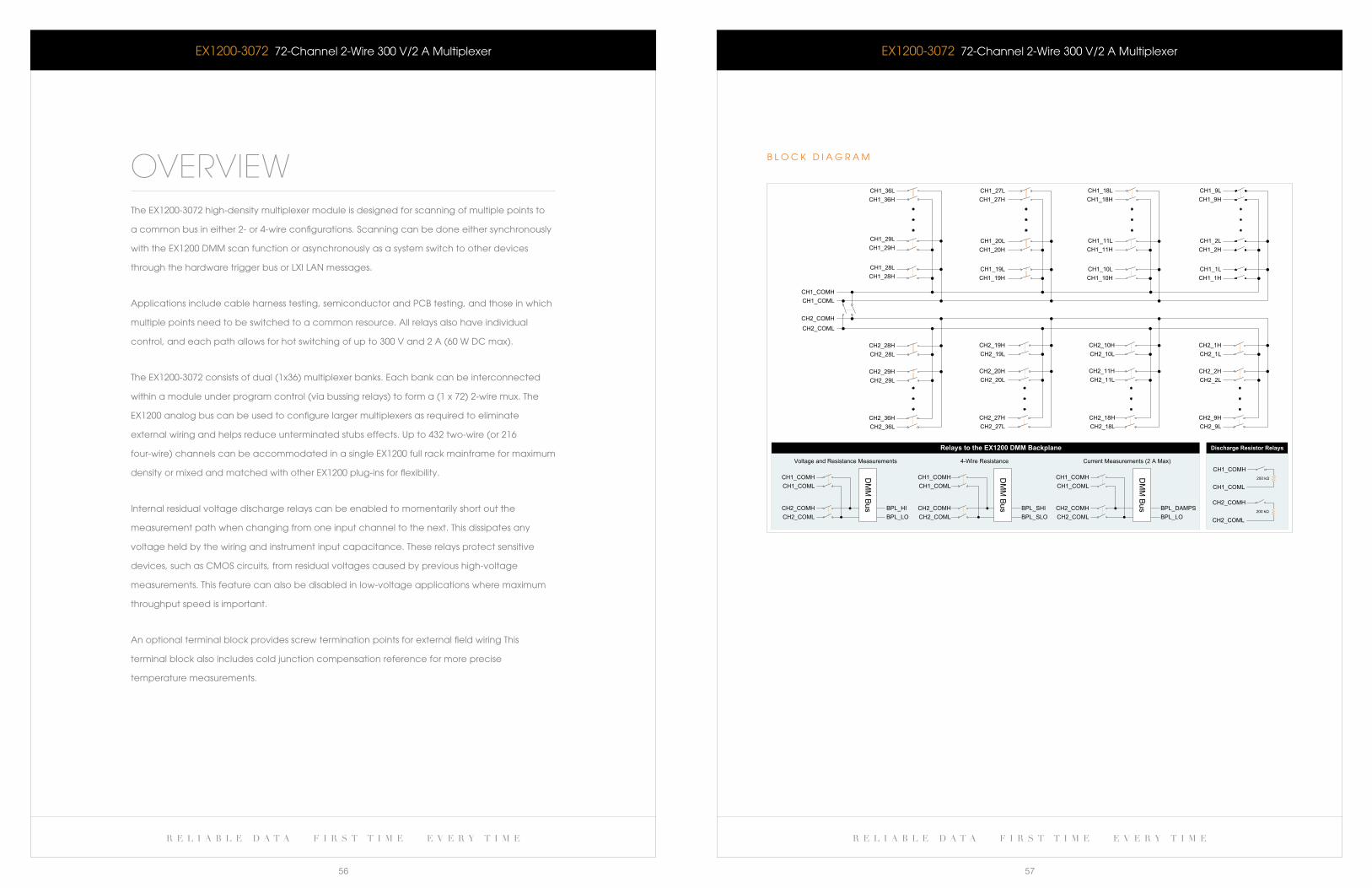
r e l i a b l e d a t a f i r s t t i m e e v e r y t i m e r e l i a b l e d a t a f i r s t t i m e e v e r y t i m e
56 57
eX1200-3072 72-channel 2-wire 300 V/2 a Multiplexer
OVERVIEWThe eX1200-3072 high-density multiplexer module is designed for scanning of multiple points to
a common bus in either 2- or 4-wire configurations. Scanning can be done either synchronously
with the eX1200 DMM scan function or asynchronously as a system switch to other devices
through the hardware trigger bus or lXI laN messages.
applications include cable harness testing, semiconductor and Pcb testing, and those in which
multiple points need to be switched to a common resource. all relays also have individual
control, and each path allows for hot switching of up to 300 V and 2 a (60 w Dc max).
The eX1200-3072 consists of dual (1x36) multiplexer banks. each bank can be interconnected
within a module under program control (via bussing relays) to form a (1 x 72) 2-wire mux. The
eX1200 analog bus can be used to configure larger multiplexers as required to eliminate
external wiring and helps reduce unterminated stubs effects. Up to 432 two-wire (or 216
four-wire) channels can be accommodated in a single eX1200 full rack mainframe for maximum
density or mixed and matched with other eX1200 plug-ins for flexibility.
Internal residual voltage discharge relays can be enabled to momentarily short out the
measurement path when changing from one input channel to the next. This dissipates any
voltage held by the wiring and instrument input capacitance. These relays protect sensitive
devices, such as cMOS circuits, from residual voltages caused by previous high-voltage
measurements. This feature can also be disabled in low-voltage applications where maximum
throughput speed is important.
an optional terminal block provides screw termination points for external field wiring This
terminal block also includes cold junction compensation reference for more precise
temperature measurements.
eX1200-3072 72-channel 2-wire 300 V/2 a Multiplexer
200 kΩ
200 kΩ
CH1_COMH
CH1_COML
CH2_COMH
CH2_COML
CH1_COMHCH1_COML
CH2_COMHCH2_COML
DM
M Bus BPL_HI
BPL_LO
DM
M Bus BPL_SHI
BPL_SLO
CH1_COMHCH1_COML
CH2_COMHCH2_COML
DM
M Bus BPL_DAMPS
BPL_LO
CH1_COMHCH1_COML
CH2_COMHCH2_COML
CH1_COMHCH1_COML
CH2_COMH
CH2_COML
CH1_1LCH1_1H
CH1_10LCH1_10HCH1_19H
CH1_19LCH1_28HCH1_28L
CH1_2LCH1_2H
CH1_11LCH1_11HCH1_20H
CH1_20LCH1_29HCH1_29L
CH1_18HCH1_18L CH1_9L
CH1_9HCH1_27HCH1_27L
CH1_36HCH1_36L
CH2_9HCH2_9L
CH2_18HCH2_18L
CH2_27HCH2_27L
CH2_36HCH2_36L
CH2_2HCH2_2L
CH2_11HCH2_11L
CH2_20HCH2_20L
CH2_29HCH2_29L
CH2_1HCH2_1L
CH2_10HCH2_10L
CH2_19HCH2_19L
CH2_28HCH2_28L
Voltage and Resistance Measurements 4-Wire Resistance Current Measurements (2 A Max)
Relays to the EX1200 DMM Backplane Discharge Resistor Relays
b l O c k D I a G R a M
w w w . v t i i n s t r u m e n t s . c o m
D a T a S H e e T
r e l i a b l e d a t a f i r s t t i m e e v e r y t i m e
59
r e l i a b l e d a t a f i r s t t i m e e v e r y t i m e
58
eX1200-3072 72-channel 2-wire 300 V/2 a Multiplexer
CHannel COUnT (1 x 72) 2-wire, dual (1 x 36) 2-wire, or (1 x 36) 4-wire
relay TyPe electromechanical, fail-safe
MaXiMUM sWiTCHing VOlTage 300 V aC rms, 300 V DC
MaXiMUM sWiTCHing CUrrenT 2 a
MaXiMUM sWiTCHing POWer¹ 60 W DC, 125 Va
MiniMUM COnTaCT raTing² 10 mV DC, 10 μa (resistive)
raTeD sWiTCH OPeraTiOns
Mechanical 1 x 10⁸ (no load)
electrical 1 x 10⁶ @ 50 V DC, 0.1 a resistive or 10 V DC, 10 ma (resistive)
sWiTCHing TiMe < 3 ms
PaTH resisTanCe < 500 mΩ
insUlaTiOn resisTanCe > 1 X 10⁹ Ω
MaXiMUM THerMal OffseT Per CHannel (Hi-lO) < 3 μV
CaPaCiTanCe
Open channel < 50 pf
Channel-mainframe < 20 pf
High-low < 50 pf
banDWiDTH (-3 db) 40 MHz (typical)
CrOssTalk (TyPiCal)
1 MHz < -70 db
10 MHz < -50 db
isOlaTiOn (TyPiCal)
1 MHz < -55 db
10 MHz < -35 db
COnneCTOr TyPe 160-pin
notes:
1. Maximum switched power is derated non-linearly as voltage is increased.
2. This value is in reference to a resistive load. Minimum capacity changes depending on
switching frequency and environmental conditions.
General Specifications
Ordering InformationeX1200-3072 72-channel, 300 V/2 a multiplexer
70-0363-504
70-0363-503
52-0109-000
27-0088-160
46-0010-000
46-0011-000
70-0363-505
70-0367-002
strain relief bracket (includes connector, recommended accessory)
strain relief bracket kit (without connector)
Crimp pin (includes 100 crimp pins)
Mating connector (one per board)
Crimp tool (Din)
extraction tool (Din)
160-pin, unterminated cable assembly, 3 ft
eX1200-Tb160-1 terminal block, differential module
aCCessOries anD TOOls
F e a T U R e S
Ultra high-density multiplexing/scanning
(1x576 2-wire channels in full rack mainframe)
Twoindividual(1x48)2-wiremultiplexer
banks programmably combinable to form
a 1x96 multiplexer.
configure as 2- or 4-wire multiplexers under
program control
Internal capacitive discharge relays keep
high voltages from disturbing sensitive
measurement points
Supports thermocouple, RTD, and
thermistor measurements
Optional screw-terminal junction box
includes built-in cold-junction compensation
Direct routing to DMM through internal analog
measurement bus simplifies field wiring
eX1200-30969 6 - c H a N N e l 1 0 0 V / 0 . 5 a T w O - w I R e M U lT I P l e X e R
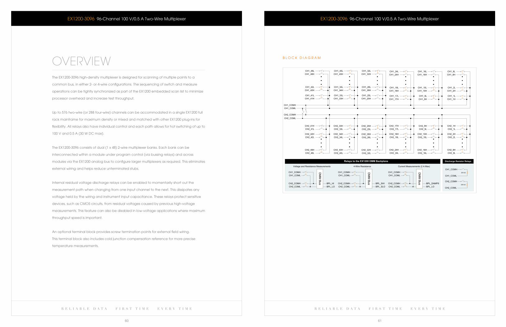
r e l i a b l e d a t a f i r s t t i m e e v e r y t i m e r e l i a b l e d a t a f i r s t t i m e e v e r y t i m e
60 61
eX1200-3096 96-channel 100 V/0.5 a Two-wire Multiplexer
OVERVIEWThe eX1200-3096 high-density multiplexer is designed for scanning of multiple points to a
common bus, in either 2- or 4-wire configurations. The sequencing of switch and measure
operations can be tightly synchronized as part of the eX1200 embedded scan list to minimize
processor overhead and increase test throughput.
Upto576two-wire(or288four-wire)channelscanbeaccommodatedinasingleEX1200full
rack mainframe for maximum density or mixed and matched with other eX1200 plug-ins for
flexibility. all relays also have individual control and each path allows for hot switching of up to
100 V and 0.5 a (30 w Dc max).
TheEX1200-3096consistsofdual(1x48)2-wiremultiplexerbanks.Eachbankcanbe
interconnected within a module under program control (via bussing relays) and across
modules via the eX1200 analog bus to configure larger multiplexers as required. This eliminates
external wiring and helps reduce unterminated stubs.
Internal residual voltage discharge relays can be enabled to momentarily short out the
measurement path when changing from one input channel to the next. This dissipates any
voltage held by the wiring and instrument input capacitance. These relays protect sensitive
devices, such as cMOS circuits, from residual voltages caused by previous high-voltage
measurements. This feature can also be disabled in low-voltage applications where maximum
throughput speed is important.
an optional terminal block provides screw termination points for external field wiring.
This terminal block also includes cold junction compensation reference for more precise
temperature measurements.
eX1200-3096 96-channel 100 V/0.5 a Two-wire Multiplexer
CH1_COMHCH1_COML
CH2_COMH
CH2_COML
CH1_1HCH1_9HCH1_17HCH1_25HCH1_33HCH1_41H
CH2_8HCH2_8L
CH2_16HCH2_16L
CH2_24HCH2_24L
CH2_32HCH2_32L
CH2_40HCH2_40L
CH2_48HCH2_48L
CH2_2HCH2_2L
CH2_10HCH2_10L
CH2_18HCH2_18L
CH2_26HCH2_26L
CH2_34HCH2_34L
CH2_42HCH2_42L
CH2_1HCH2_1L
CH2_9HCH2_9L
CH2_17HCH2_17L
CH2_25HCH2_25L
CH2_33HCH2_33L
CH2_41HCH2_41L
CH1_1LCH1_9LCH1_17LCH1_25LCH1_33LCH1_41L
CH1_2LCH1_2H
CH1_10LCH1_10HCH1_18H
CH1_18LCH1_26HCH1_26L
CH1_34HCH1_34L
CH1_42HCH1_42L
CH1_8HCH1_8LCH1_16L
CH1_16HCH1_24HCH1_24L
CH1_32HCH1_32L
CH1_40HCH1_40L
CH1_48HCH1_48L
200 kΩ
200 kΩ
CH1_COMH
CH1_COML
CH2_COMH
CH2_COML
CH1_COMHCH1_COML
CH2_COMHCH2_COML
DM
M Bus BPL_HI
BPL_LO
DM
M Bus BPL_SHI
BPL_SLO
CH1_COMHCH1_COML
CH2_COMHCH2_COML
DM
M Bus BPL_DAMPS
BPL_LO
CH1_COMHCH1_COML
CH2_COMHCH2_COML
Voltage and Resistance Measurements
Discharge Resistor Relays
4-Wire Resistance Current Measurements (2 A Max)
Relays to the EX1200 DMM Backplane
b l O c k D I a G R a M
w w w . v t i i n s t r u m e n t s . c o m
D a T a S H e e T
r e l i a b l e d a t a f i r s t t i m e e v e r y t i m e
63
r e l i a b l e d a t a f i r s t t i m e e v e r y t i m e
62
eX1200-3096 96-channel 100 V/0.5 a Two-wire Multiplexer
CHannel COUnT (1 x 96) 2-wire, dual (1 x 48) 2-wire, or (1 x 48) 4-wire
relay TyPe electromechanical, fail-safe
MaXiMUM sWiTCHing VOlTage 240 V aC, 120 V DC
MaXiMUM sWiTCHing CUrrenT 1 a
MaXiMUM sWiTCHing POWer 30 W DC (resistive), 37.5 Va (resistive)
raTeD sWiTCH OPeraTiOns
Mechanical 1 x 10⁷
electrical 1 x 10⁵ @ 30 V DC, 1 a (resistive) or 125 V aC, 0.3 a (resistive)
sWiTCHing TiMe < 3 ms
PaTH resisTanCe < 500 mΩ
insUlaTiOn resisTanCe > 1 X 10⁹ Ω
MaXiMUM THerMal OffseT Per CHannel (Hi-lO) < 7 μV
CaPaCiTanCe
Open channel < 50 pf
Channel-mainframe < 20 pf
High-low < 50 pf
banDWiDTH (-3 db) 20 MHz (typical)
CrOssTalk (TyPiCal)
1 MHz < -70 db
10 MHz < -50 db
isOlaTiOn (TyPiCal)
1 MHz < -55 db
10 MHz < -45 db
COnneCTOr TyPe 200-pin
General Specifications
Ordering InformationeX1200-3096 96-channel 2-wire, 100 V/1 a multiplexer
41-0472-034
27-0388-200
27-0391-050
70-0367-004
strain relief bracket
200-pin mating connector
Crimp pin
eX1200-Tb200 terminal block, differential module
aCCessOries anD TOOls
F e a T U R e S
High-density 300 V/2 a multiplexing scanning
(upto384two-wirechannelsin1Ufootprint)
Maximum reconfigurability - 16 (1x4) blocks
individually combinable under program control
configure as 2- or 4-wire multiplexers under
program control
Supports thermocouple, RTD, and thermistor
measurements
Optional screw-terminal junction box includes
built-in cold-junction compensation
Direct routing to DMM through internal analog
measurement bus simplifies field wiring
Stub-breaking relays isolate the module from interfering
with measurements being made on other modules
eX1200-31641 6 ( 1 X 4 ) 2 - w I R e 3 0 0 V / 2 a M U l T I P l e X e R
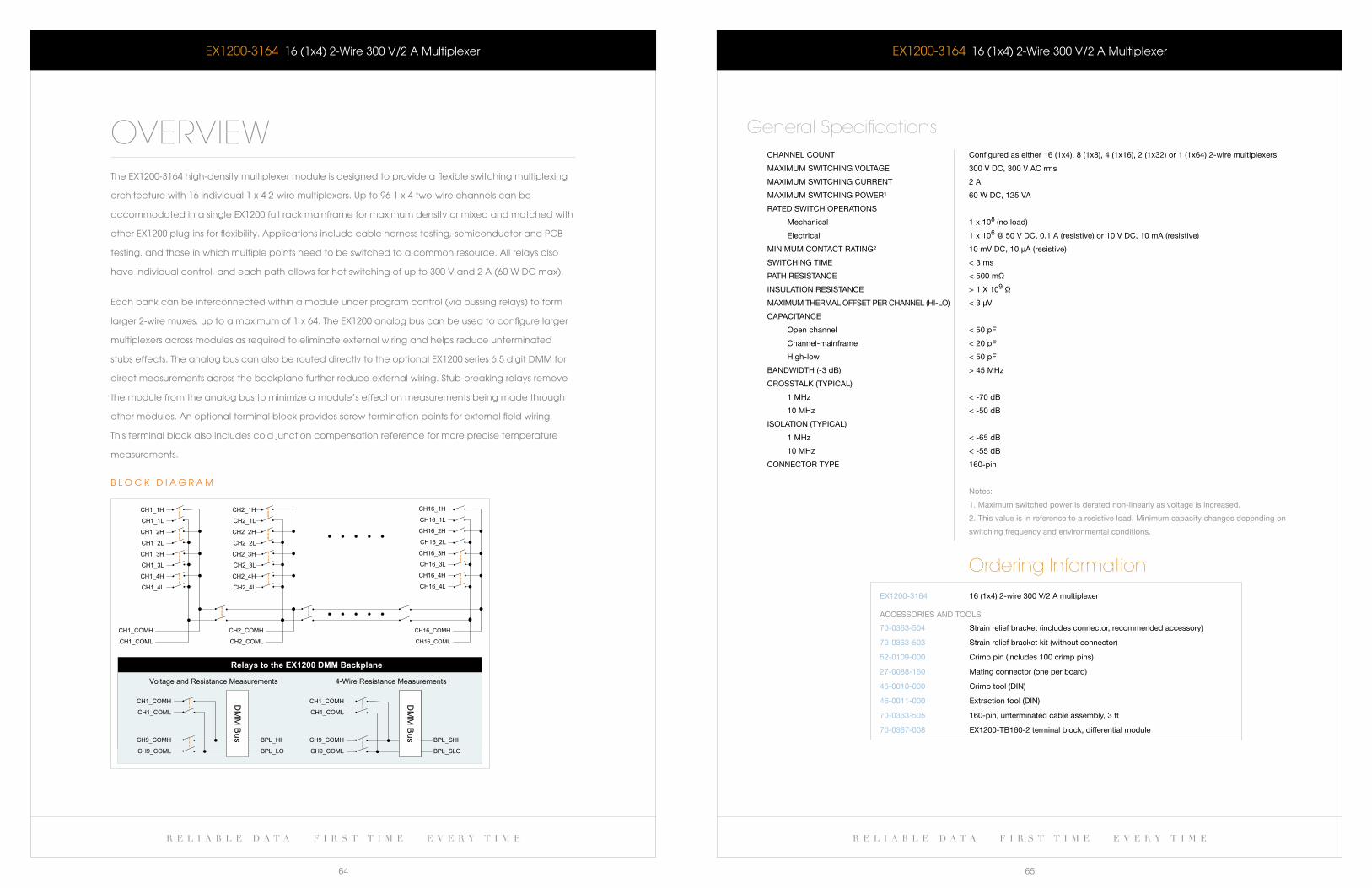
r e l i a b l e d a t a f i r s t t i m e e v e r y t i m e r e l i a b l e d a t a f i r s t t i m e e v e r y t i m e
64 65
eX1200-3164 16 (1x4) 2-wire 300 V/2 a Multiplexer
OVERVIEWThe eX1200-3164 high-density multiplexer module is designed to provide a flexible switching multiplexing
architecture with 16 individual 1 x 4 2-wire multiplexers. Up to 96 1 x 4 two-wire channels can be
accommodated in a single eX1200 full rack mainframe for maximum density or mixed and matched with
other eX1200 plug-ins for flexibility. applications include cable harness testing, semiconductor and Pcb
testing, and those in which multiple points need to be switched to a common resource. all relays also
have individual control, and each path allows for hot switching of up to 300 V and 2 a (60 w Dc max).
each bank can be interconnected within a module under program control (via bussing relays) to form
larger 2-wire muxes, up to a maximum of 1 x 64. The eX1200 analog bus can be used to configure larger
multiplexers across modules as required to eliminate external wiring and helps reduce unterminated
stubs effects. The analog bus can also be routed directly to the optional eX1200 series 6.5 digit DMM for
direct measurements across the backplane further reduce external wiring. Stub-breaking relays remove
the module from the analog bus to minimize a module’s effect on measurements being made through
other modules. an optional terminal block provides screw termination points for external field wiring.
This terminal block also includes cold junction compensation reference for more precise temperature
measurements.
CH1_1H
CH1_1L
CH1_2H
CH1_2L
CH1_3H
CH1_3L
CH1_4H
CH1_4L
CH1_COMH
CH1_COML
CH2_COMH
CH2_COML
CH2_1H
CH2_1L
CH2_2H
CH2_2L
CH2_3H
CH2_3L
CH2_4H
CH2_4L
CH16_1H
CH16_1L
CH16_2H
CH16_2L
CH16_3H
CH16_3L
CH16_4H
CH16_4L
CH16_COMH
CH16_COML
CH1_COMH
CH1_COML
CH9_COMH
CH9_COML
BPL_SHI
BPL_SLO
CH1_COMH
CH1_COML
CH9_COMH
CH9_COML
DM
M B
us BPL_HI
BPL_LO
Voltage and Resistance Measurements 4-Wire Resistance Measurements
Relays to the EX1200 DMM Backplane
DM
M B
us
b l O c k D I a G R a M
eX1200-3164 16 (1x4) 2-wire 300 V/2 a Multiplexer
CHannel COUnT Configured as either 16 (1x4), 8 (1x8), 4 (1x16), 2 (1x32) or 1 (1x64) 2-wire multiplexers
MaXiMUM sWiTCHing VOlTage 300 V DC, 300 V aC rms
MaXiMUM sWiTCHing CUrrenT 2 a
MaXiMUM sWiTCHing POWer¹ 60 W DC, 125 Va
raTeD sWiTCH OPeraTiOns
Mechanical 1 x 10⁸ (no load)
electrical 1 x 10⁶ @ 50 V DC, 0.1 a (resistive) or 10 V DC, 10 ma (resistive)
MiniMUM COnTaCT raTing² 10 mV DC, 10 μa (resistive)
sWiTCHing TiMe < 3 ms
PaTH resisTanCe < 500 mΩ
insUlaTiOn resisTanCe > 1 X 10⁹ Ω
MaXiMUM THerMal OffseT Per CHannel (Hi-lO) < 3 μV
CaPaCiTanCe
Open channel < 50 pf
Channel-mainframe < 20 pf
High-low < 50 pf
banDWiDTH (-3 db) > 45 MHz
CrOssTalk (TyPiCal)
1 MHz < -70 db
10 MHz < -50 db
isOlaTiOn (TyPiCal)
1 MHz < -65 db
10 MHz < -55 db
COnneCTOr TyPe 160-pin
notes:
1. Maximum switched power is derated non-linearly as voltage is increased.
2. This value is in reference to a resistive load. Minimum capacity changes depending on
switching frequency and environmental conditions.
General Specifications
Ordering InformationeX1200-3164 16 (1x4) 2-wire 300 V/2 a multiplexer
70-0363-504
70-0363-503
52-0109-000
27-0088-160
46-0010-000
46-0011-000
70-0363-505
70-0367-008
strain relief bracket (includes connector, recommended accessory)
strain relief bracket kit (without connector)
Crimp pin (includes 100 crimp pins)
Mating connector (one per board)
Crimp tool (Din)
extraction tool (Din)
160-pin, unterminated cable assembly, 3 ft
eX1200-Tb160-2 terminal block, differential module
aCCessOries anD TOOls
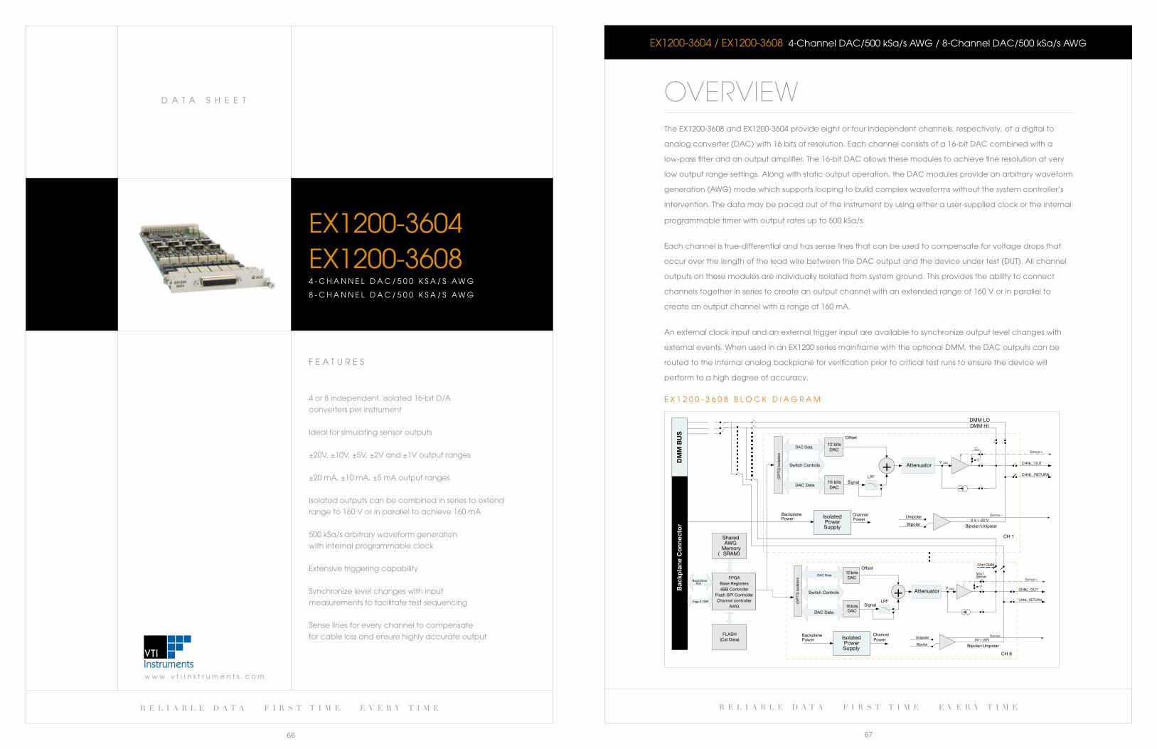
r e l i a b l e d a t a f i r s t t i m e e v e r y t i m e
67
w w w . v t i i n s t r u m e n t s . c o m
D a T a S H e e T
r e l i a b l e d a t a f i r s t t i m e e v e r y t i m e
66
F e a T U R e S
4or8independent,isolated16-bitD/A
converters per instrument
Ideal for simulating sensor outputs
±20V, ±10V, ±5V, ±2V and ±1V output ranges
±20 ma, ±10 ma, ±5 ma output ranges
Isolated outputs can be combined in series to extend
range to 160 V or in parallel to achieve 160 ma
500 kSa/s arbitrary waveform generation
with internal programmable clock
extensive triggering capability
Synchronize level changes with input
measurements to facilitate test sequencing
Sense lines for every channel to compensate
for cable loss and ensure highly accurate output
eX1200-3604EX1200-36084 - c H a N N e l D a c / 5 0 0 k S a / S aw G
8 - C H A N N E L D A C / 5 0 0 k S A / S AW G
EX1200-3604/EX1200-3608 4-ChannelDAC/500kSa/sAWG/8-ChannelDAC/500kSa/sAWG
OVERVIEWThe eX1200-3608andEX1200-3604provideeightorfourindependentchannels,respectively,ofadigitalto
analog converter (Dac) with 16 bits of resolution. each channel consists of a 16-bit Dac combined with a
low-pass filter and an output amplifier. The 16-bit Dac allows these modules to achieve fine resolution at very
low output range settings. along with static output operation, the Dac modules provide an arbitrary waveform
generation (awG) mode which supports looping to build complex waveforms without the system controller’s
intervention. The data may be paced out of the instrument by using either a user-supplied clock or the internal
programmable timer with output rates up to 500 kSa/s.
each channel is true-differential and has sense lines that can be used to compensate for voltage drops that
occur over the length of the lead wire between the Dac output and the device under test (DUT). all channel
outputs on these modules are individually isolated from system ground. This provides the ability to connect
channels together in series to create an output channel with an extended range of 160 V or in parallel to
create an output channel with a range of 160 ma.
an external clock input and an external trigger input are available to synchronize output level changes with
external events. when used in an eX1200 series mainframe with the optional DMM, the Dac outputs can be
routed to the internal analog backplane for verification prior to critical test runs to ensure the device will
perform to a high degree of accuracy.
FPGABase Registers4BB Controller
Flash SPI ControllerChannel controller
AWG
SharedAWG
Memory( SRAM)
BackplaneBus
Trigg & 1588
IsolatedPowerSupply
16 bits DAC
Switch Controls
Signal
ChannelPower
CHNL_OUT
BackplanePower
Attenuator V DAC
Sense+
0 V / -20 V
Bipolar/Unipolar
CHNL_RETURN
Sense -
VOUT
Sense
Unipolar
Bipolar
Chnl DMM
12 bits DAC
Offset
DAC Data
FLASH(Cal Data)
DMM HIDMM LO
CH 1
+LPF
DAC Data
(OP
TO) I
sola
tors
16 bits DAC
Signal
CHNL_OUTAttenuator V DAC
Sense+
0 V / -20 V
CHNL_RETURN
Sense -
VOUTSense
Unipolar
Bipolar
12 bits DAC
Offset
DAC Data
CH 8
+LPF
DM
M B
US
Bac
kpla
ne C
onn
ecto
r
Bipolar/Unipolar
IsolatedPowerSupply
(OP
TO) I
sola
tors
ChannelPower
BackplanePower
Switch Controls
DAC Data
E X 1 2 0 0 - 3 6 0 8 B L O C k D I A G R A M
r e l i a b l e d a t a f i r s t t i m e e v e r y t i m e r e l i a b l e d a t a f i r s t t i m e e v e r y t i m e
68 69
EX1200-3604/EX1200-3608 4-ChannelDAC/500kSa/sAWG/8-ChannelDAC/500kSa/sAWG
nUMber Of CHannels
eX1200-3604 4
eX1200-3608 8
resOlUTiOn 16 bits, 16 bits monotonic
TiMe/freqUenCy DOMain
settling Time 5 μs to 0.1% of specified value
rise Time¹ ≤ 800 ns
slew rate 40 V/μs typical
bandwidth 250 kHz
Crosstalk² < 65 dbV @ 10 kHz
Phase Matching
internal Channels < 50 ns when all channels are running synchronized on the internal clock
external Channels < 100 ns when all channels are running synchronized on the internal clock
TiMe frOM eXTernal Trigger reCeiPT
TO firsT saMPle OUTPUT 2.2 μs plus the rise time
eXTernal ClOCk
frequency Maximum 500 kHz
levels lVTTl
eXTernal Trigger inPUT
Pulse Width Minimum 20 ns
levels lVTTl
Marker OUTPUT
levels lVTTl
Duration 20 ns ÷ 1.34 s in 20 ns increments
Dac Specifications, Voltage ModePower Consumption
eX1200-3604
3.3 V 0.3 a
5 V 1 a
24 V 0.8 a
eX1200-3608
3.3 V 0.3 a
5 V 1 a
24 V 1 a
Output Voltage ranges
bipolar ±1 V, ±2 V, ±5 V, ±10 V, ±20 V
Unipolar 40 V
auto-ranging supported
Maximum Output (series Channels) ±160 V
Maximum frequency D C to maximum sampling rate
Output Current ±20 ma
Current Protection Current limitation circuit kicks in above 50 ma
short Circuit Time³ Up to 20 minutes. no restart necessary after short circuit
General Specifications
EX1200-3604/EX1200-3608 4-ChannelDAC/500kSa/sAWG/8-ChannelDAC/500kSa/sAWG
DCV aCCUraCy
1 V ±(0.050% of setting ±0.305 mV)
2 V ±(0.050% of setting ±0.366 mV)
5 V ±(0.050% of setting ±0.916 mV)
10 V ±(0.050% of setting ±1.831 mV)
20 V ±(0.050% of setting ±3.662 mV)
40 V ±(0.050% of setting ±7.324 mV)
DCV nOise ≤ 2 mV rms
PrOgraMMable OffseT range full-scale
riPle nOise, DCV ≤ 2 mV rms
isOlaTiOn, beTWeen CHannels 200 V
VOlTage reMOTe sensing4 High and low sense lines available per channel for cable length voltage drop compensation
Dac Specifications, current ModeOUTPUT CUrrenT ranges
ranges ±5 ma, ±10 ma, ±20 ma
Maximum Output ±160 ma
(Parallel Channels) DC to 1 kHz sampling rate
Maximum frequency DC to maximum sampling rate
OUTPUT CUrrenT sHOrT CirCUiT
Per Channel ±20 ma into short circuit
short Circuit Time5 Up to 20 minutes. no restart necessary after short circuit.
DCV aCCUraCy
5 ma ±(0.090% of setting ±1.25 μa)
10 ma ±(0.090% of setting ±2.50 μa)
20 ma ±(0.090% of setting ±5.00 μa)
COMPlianCe VOlTage 20 V
awG SpecificationsUPDaTe raTe
Programmable 20 ns (steps)
Maximum 500 ksa/s (2 μs) programmable, maximum 500 ksa/s
Trigger sOUrCes front panel input, lXisync, software
WaVefOrM size
Minimum 4 samples
Maximum 2,097,100 samples
WaVefOrMs 1 to 4096 (sW limited can be increased in the future)
seqUenCes 1 to 4096 (sW limited can be increased in the future)
WaVefOrM rePeaT COUnT 1 to 216 (65,536)
MeMOry seqUenCe rePeaT (bUrsT) COUnT 1 to 216 (65,536)
sTePs Per seqUenCe 1 to 4096 (sW limited can be increased in the future)
MODes
iVi-compliant Output modes: standard Waveform, arbitary Waveform, arbitary sequence
Operation modes: Continuous, burst
VTi instrument specific Operation modes: sequenced, single step
Marker fUnCTiOn
Output Can be sourced from any of the channels
Position Can be placed at anywhere inside a waveform
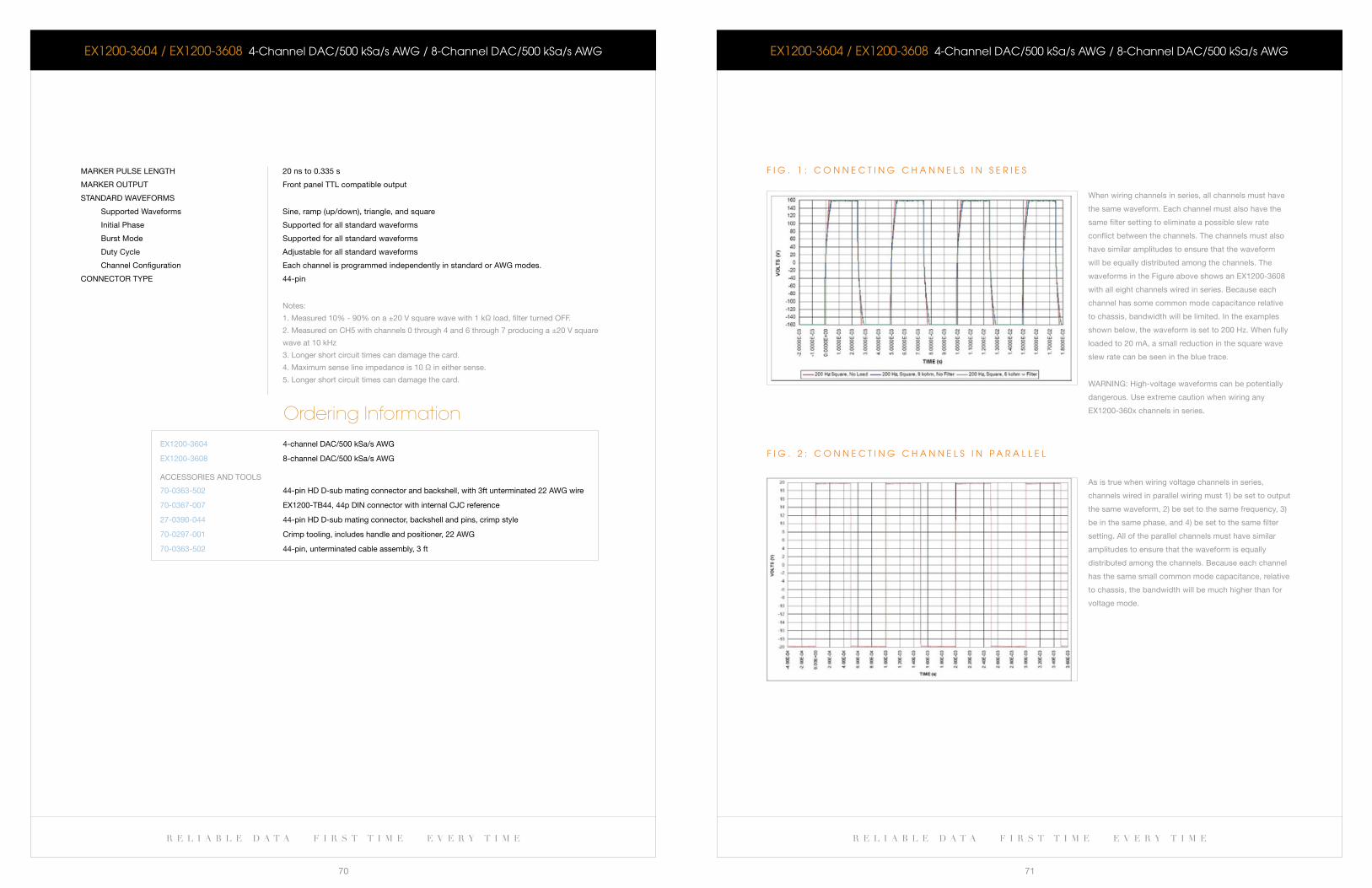
r e l i a b l e d a t a f i r s t t i m e e v e r y t i m e r e l i a b l e d a t a f i r s t t i m e e v e r y t i m e
70 71
EX1200-3604/EX1200-3608 4-ChannelDAC/500kSa/sAWG/8-ChannelDAC/500kSa/sAWG
Marker PUlse lengTH 20 ns to 0.335 s
Marker OUTPUT front panel TTl compatible output
sTanDarD WaVefOrMs
supported Waveforms sine, ramp (up/down), triangle, and square
initial Phase supported for all standard waveforms
burst Mode supported for all standard waveforms
Duty Cycle adjustable for all standard waveforms
Channel Configuration each channel is programmed independently in standard or aWg modes.
COnneCTOr TyPe 44-pin
notes:
1. Measured 10% - 90% on a ±20 V square wave with 1 kΩ load, filter turned Off.
2. Measured on CH5 with channels 0 through 4 and 6 through 7 producing a ±20 V square
wave at 10 kHz
3. longer short circuit times can damage the card.
4. Maximum sense line impedance is 10 Ω in either sense.
5. longer short circuit times can damage the card.
Ordering InformationeX1200-3604
eX1200-3608
4-channel DaC/500 ksa/s aWg
8-channel DaC/500 ksa/s aWg
70-0363-502
70-0367-007
27-0390-044
70-0297-001
70-0363-502
44-pin HD D-sub mating connector and backshell, with 3ft unterminated 22 aWg wire
eX1200-Tb44, 44p Din connector with internal CJC reference
44-pin HD D-sub mating connector, backshell and pins, crimp style
Crimp tooling, includes handle and positioner, 22 aWg
44-pin, unterminated cable assembly, 3 ft
aCCessOries anD TOOls
EX1200-3604/EX1200-3608 4-ChannelDAC/500kSa/sAWG/8-ChannelDAC/500kSa/sAWG
F I G . 2 : c O N N e c T I N G c H a N N e l S I N P a R a l l e l
as is true when wiring voltage channels in series,
channels wired in parallel wiring must 1) be set to output
the same waveform, 2) be set to the same frequency, 3)
be in the same phase, and 4) be set to the same filter
setting. all of the parallel channels must have similar
amplitudes to ensure that the waveform is equally
distributed among the channels. because each channel
has the same small common mode capacitance, relative
to chassis, the bandwidth will be much higher than for
voltage mode.
F I G . 1 : c O N N e c T I N G c H a N N e l S I N S e R I e S
When wiring channels in series, all channels must have
the same waveform. each channel must also have the
same filter setting to eliminate a possible slew rate
conflict between the channels. The channels must also
have similar amplitudes to ensure that the waveform
will be equally distributed among the channels. The
waveforms in the figure above shows an eX1200-3608
with all eight channels wired in series. because each
channel has some common mode capacitance relative
to chassis, bandwidth will be limited. in the examples
shown below, the waveform is set to 200 Hz. When fully
loaded to 20 ma, a small reduction in the square wave
slew rate can be seen in the blue trace.
Warning: High-voltage waveforms can be potentially
dangerous. Use extreme caution when wiring any
eX1200-360x channels in series.
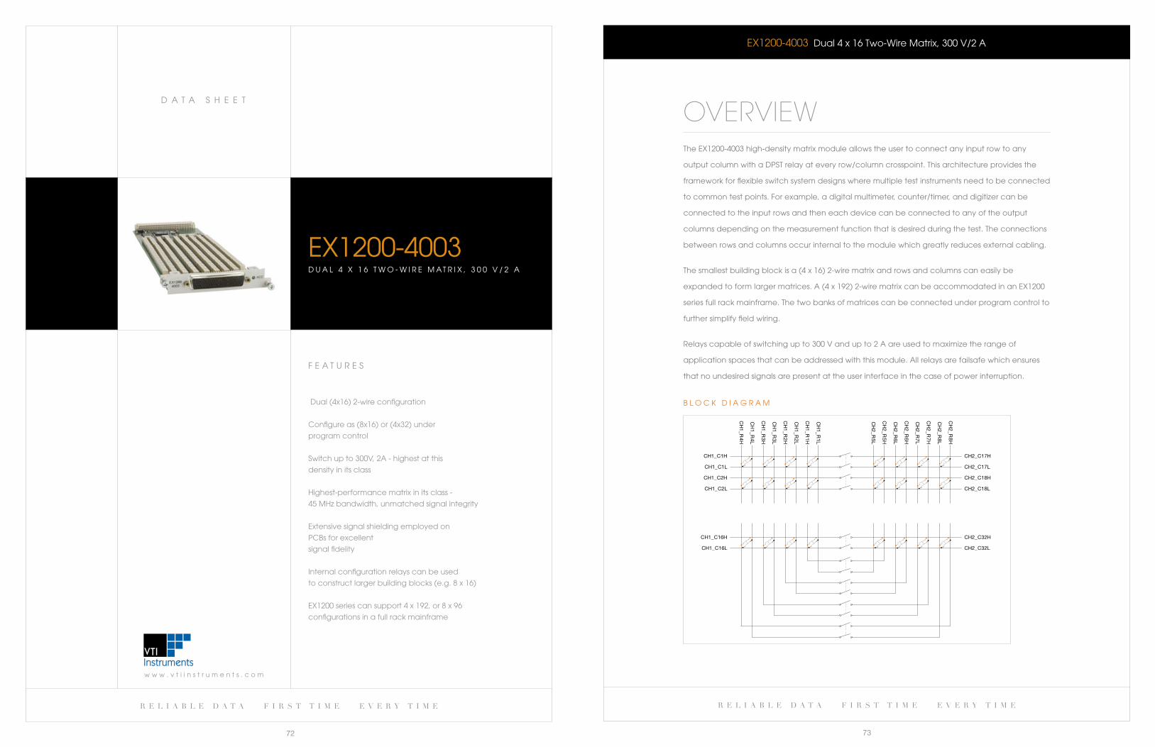
r e l i a b l e d a t a f i r s t t i m e e v e r y t i m e
73
w w w . v t i i n s t r u m e n t s . c o m
D a T a S H e e T
r e l i a b l e d a t a f i r s t t i m e e v e r y t i m e
72
F e a T U R e S
Dual (4x16) 2-wire configuration
Configureas(8x16)or(4x32)under
program control
Switch up to 300V, 2a - highest at this
density in its class
Highest-performance matrix in its class -
45 MHz bandwidth, unmatched signal integrity
extensive signal shielding employed on
Pcbs for excellent
signal fidelity
Internal configuration relays can be used
toconstructlargerbuildingblocks(e.g.8x16)
EX1200seriescansupport4x192,or8x96
configurations in a full rack mainframe
eX1200-4003D U a l 4 X 1 6 T w O - w I R e M a T R I X , 3 0 0 V / 2 a
eX1200-4003 Dual 4 x 16 Two-wire Matrix, 300 V/2 a
OVERVIEWThe eX1200-4003 high-density matrix module allows the user to connect any input row to any
output column with a DPST relay at every row/column crosspoint. This architecture provides the
framework for flexible switch system designs where multiple test instruments need to be connected
to common test points. For example, a digital multimeter, counter/timer, and digitizer can be
connected to the input rows and then each device can be connected to any of the output
columns depending on the measurement function that is desired during the test. The connections
between rows and columns occur internal to the module which greatly reduces external cabling.
The smallest building block is a (4 x 16) 2-wire matrix and rows and columns can easily be
expanded to form larger matrices. a (4 x 192) 2-wire matrix can be accommodated in an eX1200
series full rack mainframe. The two banks of matrices can be connected under program control to
further simplify field wiring.
Relays capable of switching up to 300 V and up to 2 a are used to maximize the range of
application spaces that can be addressed with this module. all relays are failsafe which ensures
that no undesired signals are present at the user interface in the case of power interruption.
CH2_C18H
CH2_C18L
CH2_C17H
CH2_C17L
CH
2_R8H
CH
2_R8L
CH
2_R7H
CH
2_R7L
CH
2_R6H
CH
2_R6L
CH
2_R5H
CH
2_R5L
CH2_C32H
CH2_C32L
CH1_C2H
CH1_C2L
CH1_C1H
CH1_C1L
CH
1_R4H
CH
1_R4L
CH
1_R3H
CH
1_R3L
CH
1_R2H
CH
1_R2L
CH
1_R1H
CH
1_R1L
CH1_C16H
CH1_C16L
b l O c k D I a G R a M
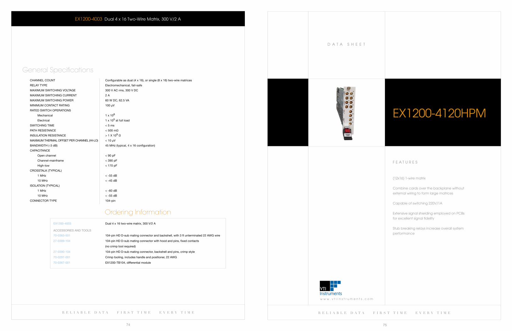
w w w . v t i i n s t r u m e n t s . c o m
D a T a S H e e T
r e l i a b l e d a t a f i r s t t i m e e v e r y t i m e
75
r e l i a b l e d a t a f i r s t t i m e e v e r y t i m e
74
eX1200-4003 Dual 4 x 16 Two-wire Matrix, 300 V/2 a
CHannel COUnT Configurable as dual (4 x 16), or single (8 x 16) two-wire matrices
relay TyPe electromechanical, fail-safe
MaXiMUM sWiTCHing VOlTage 300 V aC rms, 300 V DC
MaXiMUM sWiTCHing CUrrenT 2 a
MaXiMUM sWiTCHing POWer 60 W DC, 62.5 Va
MiniMUM COnTaCT raTing 100 μV
raTeD sWiTCH OPeraTiOns
Mechanical 1 x 10⁸
electrical 1 x 10⁵ at full load
sWiTCHing TiMe < 5 ms
PaTH resisTanCe < 500 mΩ
insUlaTiOn resisTanCe > 1 X 10⁹ Ω
MaXiMUM THerMal OffseT Per CHannel (Hi-lO) < 10 μV
banDWiDTH (-3 db) 45 MHz (typical, 4 x 16 configuration)
CaPaCiTanCe
Open channel < 90 pf
Channel-mainframe < 390 pf
High-low < 170 pf
CrOssTalk (TyPiCal)
1 MHz < -55 db
10 MHz < -45 db
isOlaTiOn (TyPiCal)
1 MHz < -60 db
10 MHz < -55 db
COnneCTOr TyPe 104-pin
General Specifications
Ordering InformationeX1200-4003 Dual 4 x 16 two-wire matrix, 300 V/2 a
70-0363-501
27-0389-104
27-0390-104
70-0297-001
70-0367-001
104-pin HD D-sub mating connector and backshell, with 3 ft unterminated 22 aWg wire
104-pin HD D-sub mating connector with hood and pins, fixed contacts
(no crimp tool required)
104-pin HD D-sub mating connector, backshell and pins, crimp style
Crimp tooling, includes handle and positioner, 22 aWg
eX1200-Tb104, differential module
aCCessOries anD TOOls
F e a T U R e S
(12x16) 1-wire matrix
combine cards over the backplane without
external wiring to form large matrices
capable of switching 220V/1a
extensive signal shielding employed on Pcbs
for excellent signal fidelity
Stub breaking relays increase overall system
performance
eX1200-4120HPM
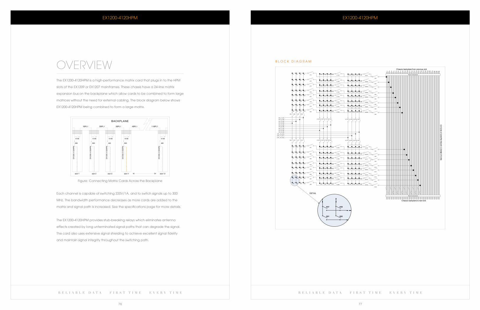
r e l i a b l e d a t a f i r s t t i m e e v e r y t i m e r e l i a b l e d a t a f i r s t t i m e e v e r y t i m e
76 77
eX1200-4120HPM
b l O c k D I a G R a M
eX1200-4120HPM
OVERVIEWThe eX1200-4120HPM is a high-performance matrix card that plugs in to the HPM
slots of the eX1209 or eX1207 mainframes. These chassis have a 24-line matrix
expansion bus on the backplane which allow cards to be combined to form large
matrices without the need for external cabling. The block diagram below shows
eX1200-4120HPM being combined to form a large matrix.
each channel is capable of switching 220V/1a, and to switch signals up to 300
MHz. The bandwidth performance decreases as more cards are added to the
matrix and signal path is increased. See the specifications page for more details.
The eX1200-4120HPM provides stub-breaking relays which eliminates antenna
effects created by long unterminated signal paths that can degrade the signal.
The card also uses extensive signal shielding to achieve excellent signal fidelity
and maintain signal integrity throughout the switching path.
Figure: connecting Matrix cards across the backplane
BACKPLANE
1BPL1 2BPL1 3BPL1 4BPL1 11BPL1
K106 K106 K106 K106 K106
K80 K80 k80 K80 k80
slot 1 slot 2 slot 3 slot 4 slot 12
EX
1200
-412
0HP
M
EX
1200
-412
0HP
M
EX
1200
-412
0HP
M
EX
1200
-412
0HP
M
EX
1200
-412
0HP
M
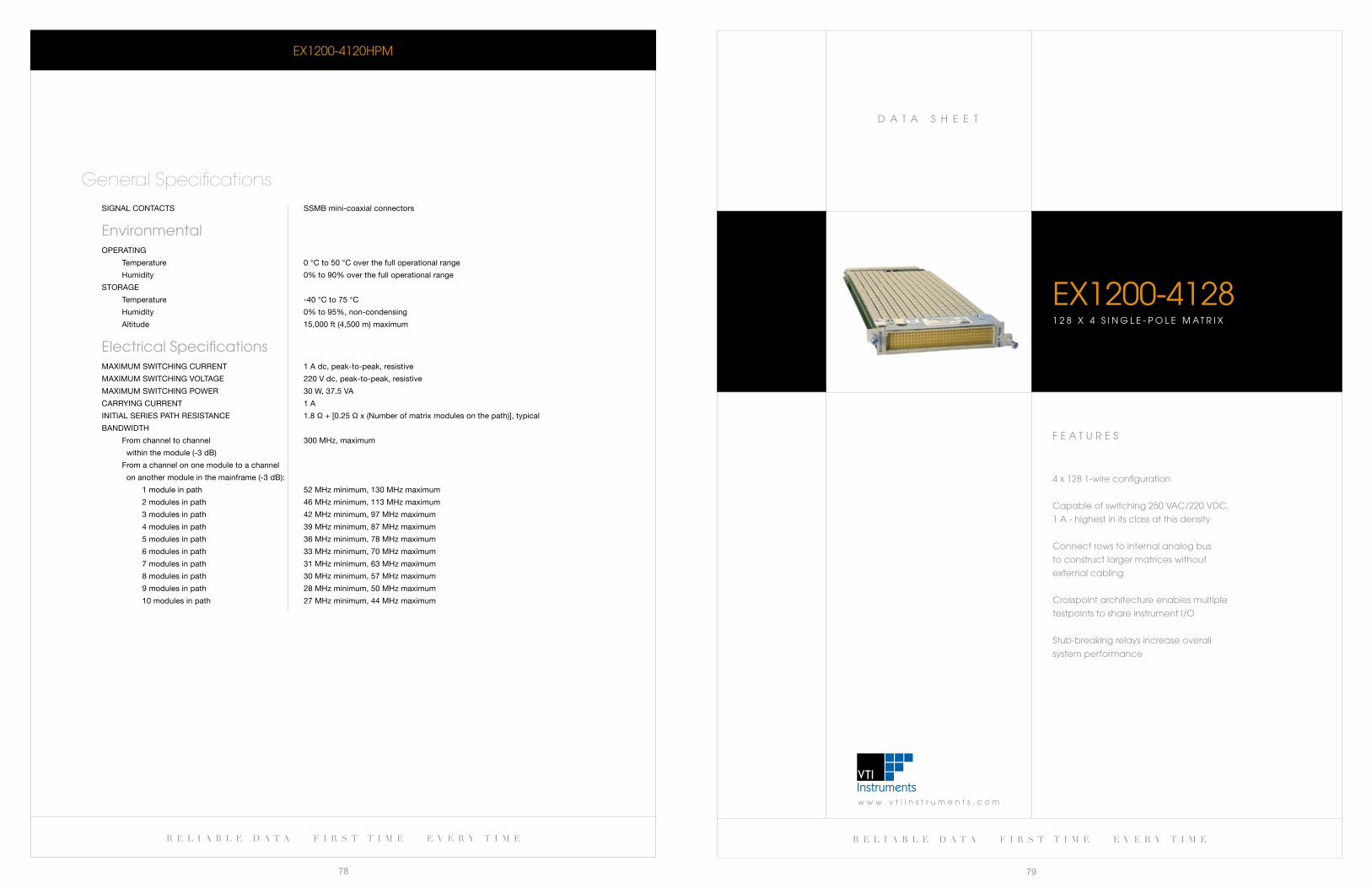
w w w . v t i i n s t r u m e n t s . c o m
D a T a S H e e T
r e l i a b l e d a t a f i r s t t i m e e v e r y t i m e
79
r e l i a b l e d a t a f i r s t t i m e e v e r y t i m e
78
F e a T U R e S
4x1281-wireconfiguration
capable of switching 250 Vac/220 VDc,
1 a - highest in its class at this density
connect rows to internal analog bus
to construct larger matrices without
external cabling
crosspoint architecture enables multiple
testpoints to share instrument I/O
Stub-breaking relays increase overall
system performance
EX1200-41281 2 8 X 4 S I N G L E - P O L E M A T R I X
eX1200-4120HPM
signal COnTaCTs ssMb mini-coaxial connectors
environmental OPeraTing
Temperature 0 °C to 50 °C over the full operational range
Humidity 0% to 90% over the full operational range
sTOrage
Temperature -40 °C to 75 °C
Humidity 0% to 95%, non-condensing
altitude 15,000 ft (4,500 m) maximum
electrical Specifications MaXiMUM sWiTCHing CUrrenT 1 a dc, peak-to-peak, resistive
MaXiMUM sWiTCHing VOlTage 220 V dc, peak-to-peak, resistive
MaXiMUM sWiTCHing POWer 30 W, 37.5 Va
Carrying CUrrenT 1 a
iniTial series PaTH resisTanCe 1.8 Ω + [0.25 Ω x (number of matrix modules on the path)], typical
banDWiDTH
from channel to channel 300 MHz, maximum
within the module (-3 db)
from a channel on one module to a channel
on another module in the mainframe (-3 db):
1 module in path 52 MHz minimum, 130 MHz maximum
2 modules in path 46 MHz minimum, 113 MHz maximum
3 modules in path 42 MHz minimum, 97 MHz maximum
4 modules in path 39 MHz minimum, 87 MHz maximum
5 modules in path 36 MHz minimum, 78 MHz maximum
6 modules in path 33 MHz minimum, 70 MHz maximum
7 modules in path 31 MHz minimum, 63 MHz maximum
8 modules in path 30 MHz minimum, 57 MHz maximum
9 modules in path 28 MHz minimum, 50 MHz maximum
10 modules in path 27 MHz minimum, 44 MHz maximum
General Specifications
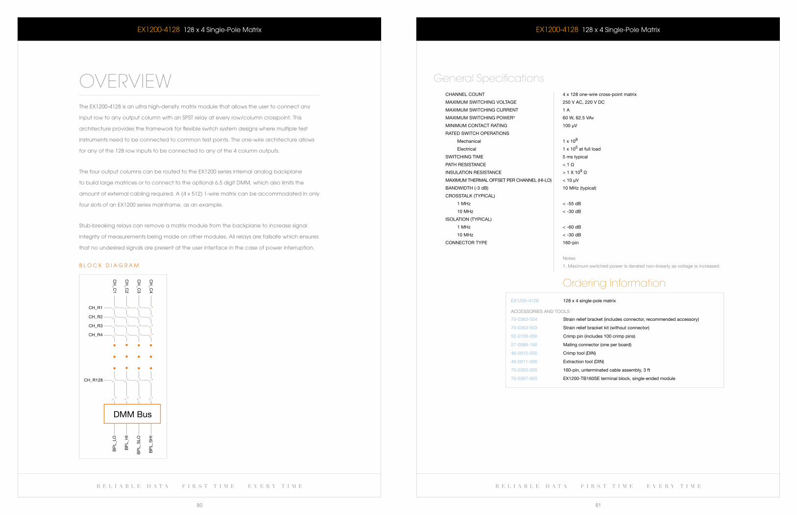
r e l i a b l e d a t a f i r s t t i m e e v e r y t i m e r e l i a b l e d a t a f i r s t t i m e e v e r y t i m e
80 81
EX1200-4128 128x4Single-PoleMatrix
CHannel COUnT 4 x 128 one-wire cross-point matrix
MaXiMUM sWiTCHing VOlTage 250 V aC, 220 V DC
MaXiMUM sWiTCHing CUrrenT 1 a
MaXiMUM sWiTCHing POWer¹ 60 W, 62.5 Vav
MiniMUM COnTaCT raTing 100 μV
raTeD sWiTCH OPeraTiOns
Mechanical 1 x 10⁸
electrical 1 x 10⁵ at full load
sWiTCHing TiMe 5 ms typical
PaTH resisTanCe < 1 Ω
insUlaTiOn resisTanCe > 1 X 10⁹ Ω
MaXiMUM THerMal OffseT Per CHannel (Hi-lO) < 10 μV
banDWiDTH (-3 db) 10 MHz (typical)
CrOssTalk (TyPiCal)
1 MHz < -55 db
10 MHz < -30 db
isOlaTiOn (TyPiCal)
1 MHz < -60 db
10 MHz < -30 db
COnneCTOr TyPe 160-pin
notes:
1. Maximum switched power is derated non-linearly as voltage is increased.
General Specifications
Ordering InformationeX1200-4128 128 x 4 single-pole matrix
70-0363-504
70-0363-503
52-0109-000
27-0088-160
46-0010-000
46-0011-000
70-0363-505
70-0367-005
strain relief bracket (includes connector, recommended accessory)
strain relief bracket kit (without connector)
Crimp pin (includes 100 crimp pins)
Mating connector (one per board)
Crimp tool (Din)
extraction tool (Din)
160-pin, unterminated cable assembly, 3 ft
eX1200-Tb160se terminal block, single-ended module
aCCessOries anD TOOls
EX1200-4128 128x4Single-PoleMatrix
OVERVIEWTheEX1200-4128isanultrahigh-densitymatrixmodulethatallowstheusertoconnectany
input row to any output column with an SPST relay at every row/column crosspoint. This
architecture provides the framework for flexible switch system designs where multiple test
instruments need to be connected to common test points. The one-wire architecture allows
foranyofthe128rowinputstobeconnectedtoanyofthe4columnoutputs.
The four output columns can be routed to the eX1200 series internal analog backplane
to build large matrices or to connect to the optional 6.5 digit DMM, which also limits the
amount of external cabling required. a (4 x 512) 1-wire matrix can be accommodated in only
four slots of an eX1200 series mainframe, as an example.
Stub-breaking relays can remove a matrix module from the backplane to increase signal
integrity of measurements being made on other modules. all relays are failsafe which ensures
that no undesired signals are present at the user interface in the case of power interruption.
CH_R1
CH_R2
CH_R3
CH_R4
CH
_C1
CH
_C2
CH
_C3
CH
_C4
CH_R128
BP
L_LO
BP
L_H
I
BP
L_S
LO
BP
L_S
HI
DMM Bus
b l O c k D I a G R a M
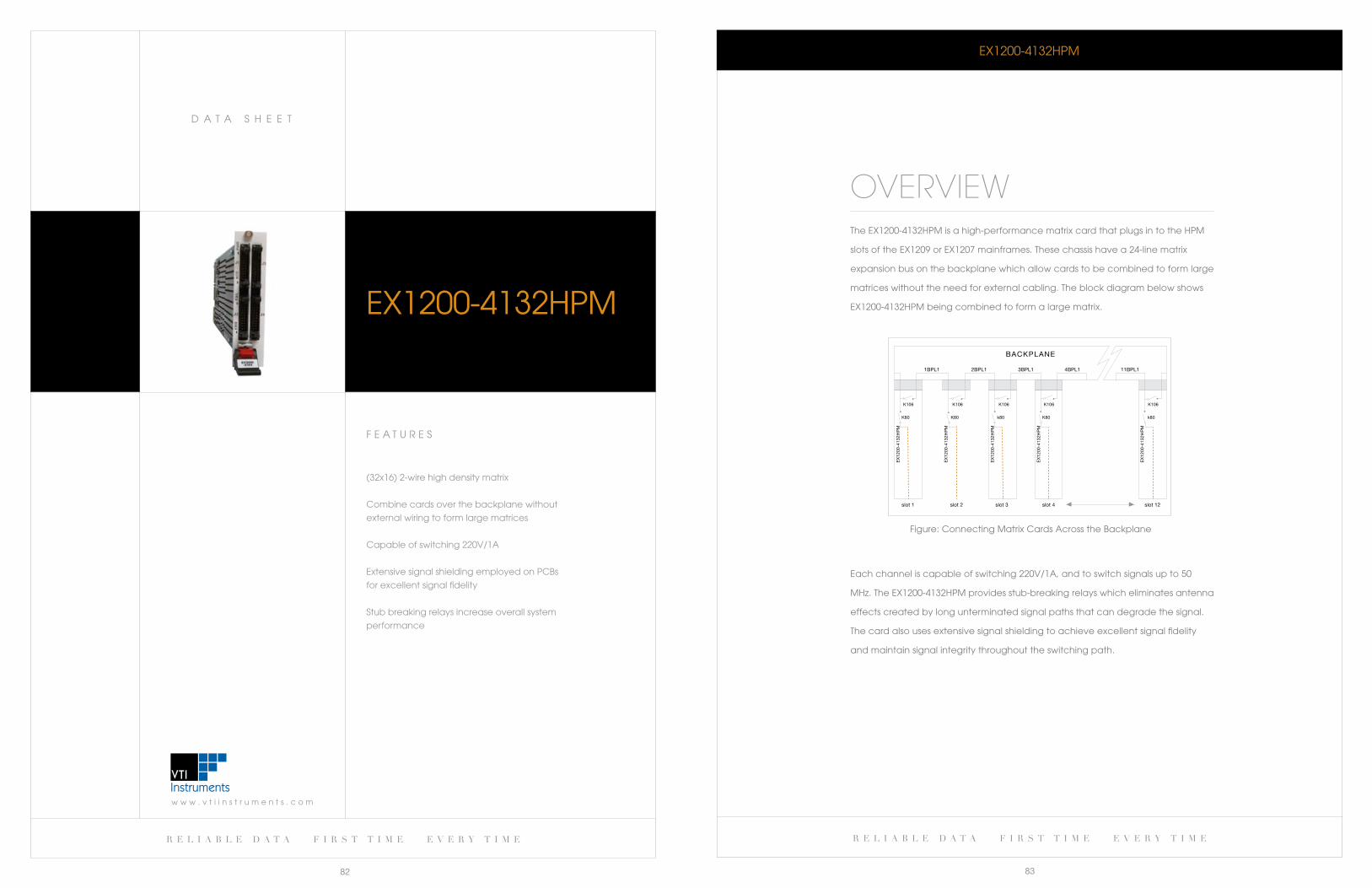
r e l i a b l e d a t a f i r s t t i m e e v e r y t i m e
83
w w w . v t i i n s t r u m e n t s . c o m
D a T a S H e e T
r e l i a b l e d a t a f i r s t t i m e e v e r y t i m e
82
eX1200-4132HPM
OVERVIEWThe eX1200-4132HPM is a high-performance matrix card that plugs in to the HPM
slots of the eX1209 or eX1207 mainframes. These chassis have a 24-line matrix
expansion bus on the backplane which allow cards to be combined to form large
matrices without the need for external cabling. The block diagram below shows
eX1200-4132HPM being combined to form a large matrix.
each channel is capable of switching 220V/1a, and to switch signals up to 50
MHz. The eX1200-4132HPM provides stub-breaking relays which eliminates antenna
effects created by long unterminated signal paths that can degrade the signal.
The card also uses extensive signal shielding to achieve excellent signal fidelity
and maintain signal integrity throughout the switching path.
Figure: connecting Matrix cards across the backplane
BACKPLANE
1BPL1 2BPL1 3BPL1 4BPL1 11BPL1
K106 K106 K106 K106 K106
K80 K80 k80 K80 k80
slot 1 slot 2 slot 3 slot 4 slot 12
EX
1200
-413
2HP
M
EX
1200
-413
2HP
M
EX
1200
-413
2HP
M
EX
1200
-413
2HP
M
EX
1200
-413
2HP
M
F e a T U R e S
(32x16) 2-wire high density matrix
combine cards over the backplane without
external wiring to form large matrices
capable of switching 220V/1a
extensive signal shielding employed on Pcbs
for excellent signal fidelity
Stub breaking relays increase overall system
performance
eX1200-4132HPM
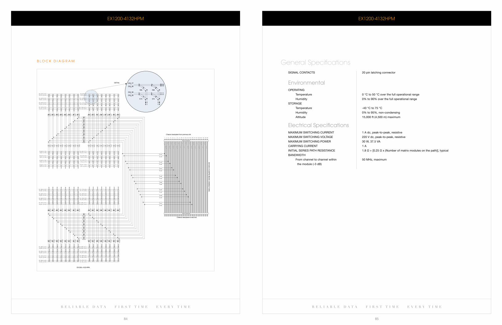
r e l i a b l e d a t a f i r s t t i m e e v e r y t i m e r e l i a b l e d a t a f i r s t t i m e e v e r y t i m e
84 85
eX1200-4132HPM
signal COnTaCTs 20 pin latching connector
environmentalOPeraTing
Temperature 0 °C to 50 °C over the full operational range
Humidity 0% to 90% over the full operational range
sTOrage
Temperature -40 °C to 75 °C
Humidity 0% to 95%, non-condensing
altitude 15,000 ft (4,500 m) maximum
electrical Specifications MaXiMUM sWiTCHing CUrrenT 1 a dc, peak-to-peak, resistive
MaXiMUM sWiTCHing VOlTage 220 V dc, peak-to-peak, resistive
MaXiMUM sWiTCHing POWer 30 W, 37.5 Va
Carrying CUrrenT 1 a
iniTial series PaTH resisTanCe 1.8 Ω + [0.25 Ω x (number of matrix modules on the path)], typical
banDWiDTH
from channel to channel within 50 MHz, maximum
the module (-3 db)
General Specifications
b l O c k D I a G R a M
eX1200-4132HPM
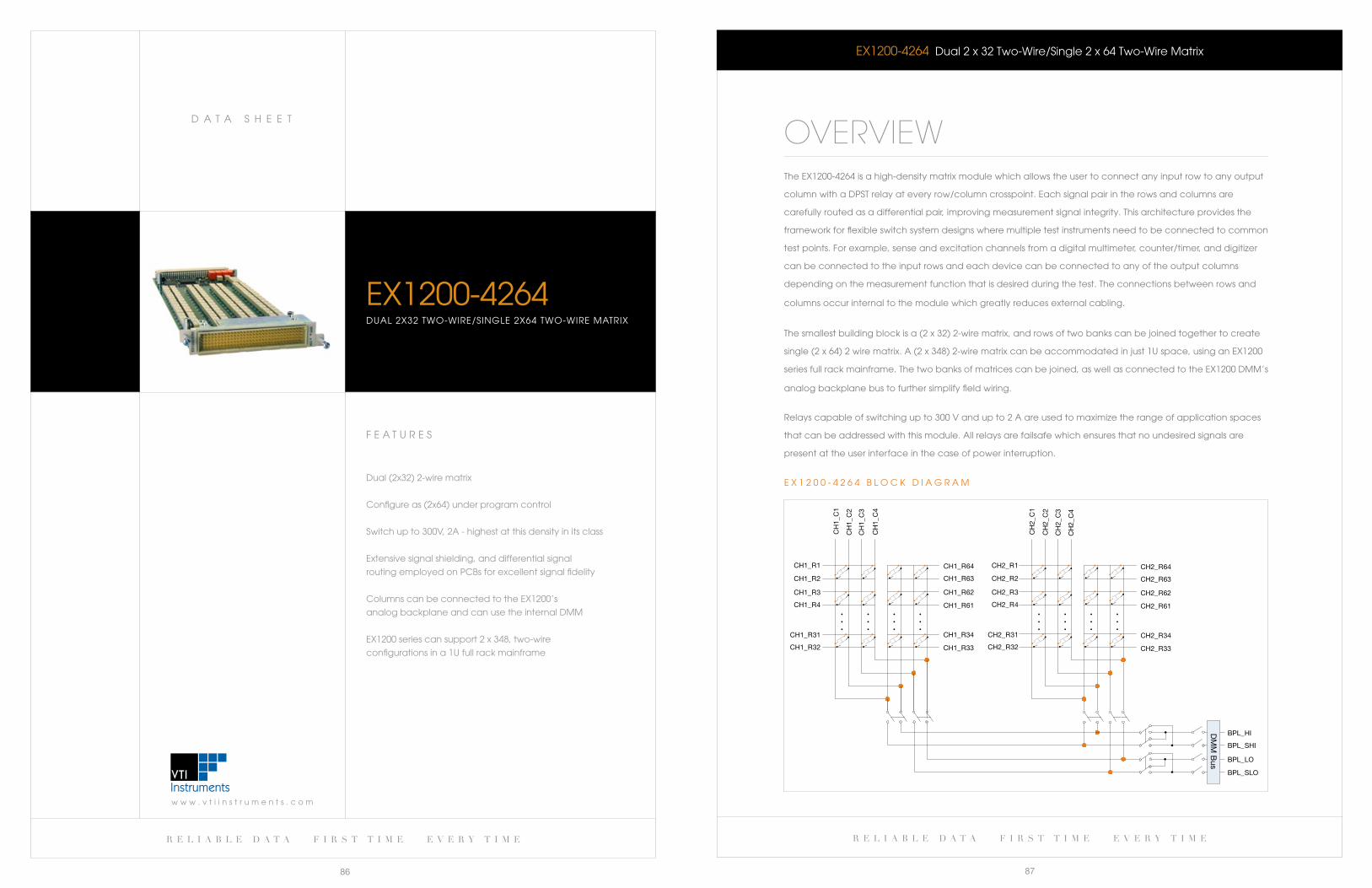
r e l i a b l e d a t a f i r s t t i m e e v e r y t i m e
87
w w w . v t i i n s t r u m e n t s . c o m
D a T a S H e e T
r e l i a b l e d a t a f i r s t t i m e e v e r y t i m e
86
eX1200-4264 Dual 2 x 32 Two-wire/Single 2 x 64 Two-wire Matrix
OVERVIEWThe eX1200-4264 is a high-density matrix module which allows the user to connect any input row to any output
column with a DPST relay at every row/column crosspoint. each signal pair in the rows and columns are
carefully routed as a differential pair, improving measurement signal integrity. This architecture provides the
framework for flexible switch system designs where multiple test instruments need to be connected to common
test points. For example, sense and excitation channels from a digital multimeter, counter/timer, and digitizer
can be connected to the input rows and each device can be connected to any of the output columns
depending on the measurement function that is desired during the test. The connections between rows and
columns occur internal to the module which greatly reduces external cabling.
The smallest building block is a (2 x 32) 2-wire matrix, and rows of two banks can be joined together to create
single(2x64)2wirematrix.A(2x348)2-wirematrixcanbeaccommodatedinjust1Uspace,usinganEX1200
series full rack mainframe. The two banks of matrices can be joined, as well as connected to the eX1200 DMM’s
analog backplane bus to further simplify field wiring.
Relays capable of switching up to 300 V and up to 2 a are used to maximize the range of application spaces
that can be addressed with this module. all relays are failsafe which ensures that no undesired signals are
present at the user interface in the case of power interruption.
CH1_R1
CH1_R2
CH1_R3
CH1_R4
CH1_R33
CH1_R34CH1_R31
CH1_R32
CH1_R61
CH1_R62
CH1_R63
CH1_R64
CH2_R33
CH2_R34
CH2_R61
CH2_R62
CH2_R63
CH2_R64
BPL_LO
BPL_SHI
CH2_R1
CH2_R2
CH2_R3
CH2_R4
CH2_R31
CH2_R32
CH
1_C
1
CH
1_C
2
CH
1_C
3
CH
1_C
4
CH
2_C
1
CH
2_C
2
CH
2_C
3
CH
2_C
4
BPL_SLO
BPL_HIDM
M B
us
e X 1 2 0 0 - 4 2 6 4 b l O c k D I a G R a M
F e a T U R e S
Dual (2x32) 2-wire matrix
configure as (2x64) under program control
Switch up to 300V, 2a - highest at this density in its class
extensive signal shielding, and differential signal
routing employed on Pcbs for excellent signal fidelity
columns can be connected to the eX1200’s
analog backplane and can use the internal DMM
EX1200seriescansupport2x348,two-wire
configurations in a 1U full rack mainframe
eX1200-4264DUal 2X32 TwO-wIRe/SINGle 2X64 TwO-wIRe MaTRIX
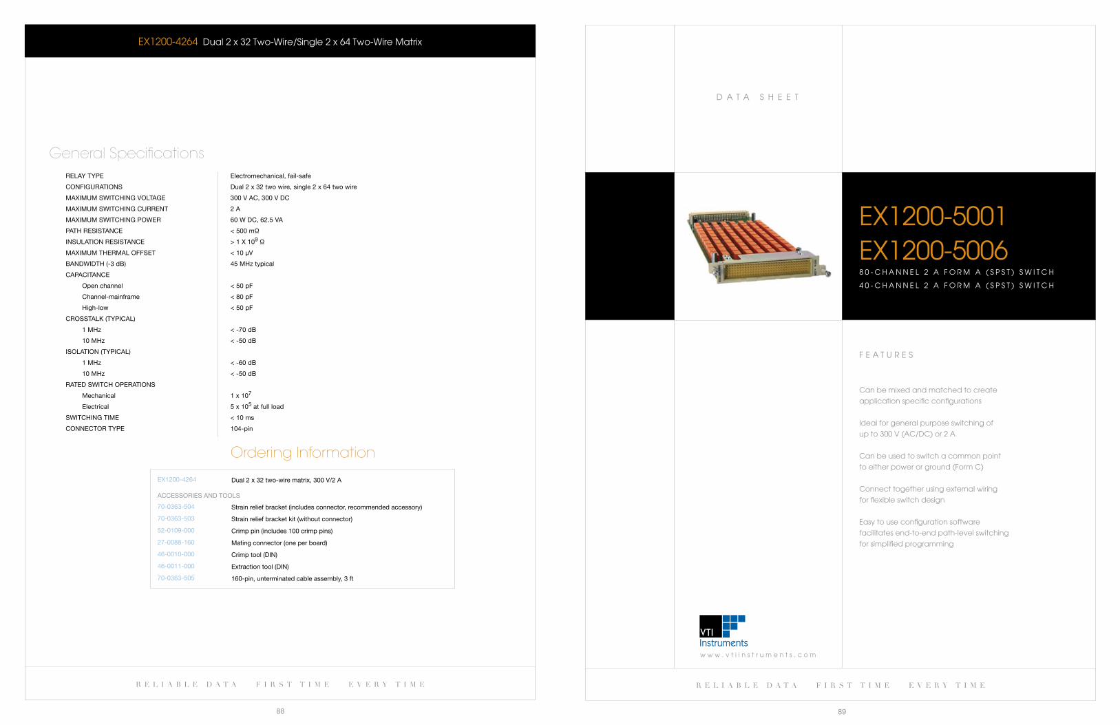
w w w . v t i i n s t r u m e n t s . c o m
D a T a S H e e T
r e l i a b l e d a t a f i r s t t i m e e v e r y t i m e
89
r e l i a b l e d a t a f i r s t t i m e e v e r y t i m e
88
F e a T U R e S
can be mixed and matched to create
application specific configurations
Ideal for general purpose switching of
up to 300 V (ac/Dc) or 2 a
can be used to switch a common point
to either power or ground (Form c)
connect together using external wiring
for flexible switch design
easy to use configuration software
facilitates end-to-end path-level switching
for simplified programming
eX1200-5001eX1200-50068 0 - C H A N N E L 2 A F O R M A ( S P S T ) S W I T C H
4 0 - c H a N N e l 2 a F O R M a ( S P S T ) S w I T c H
eX1200-4264 Dual 2 x 32 Two-wire/Single 2 x 64 Two-wire Matrix
relay TyPe electromechanical, fail-safe
COnfigUraTiOns Dual 2 x 32 two wire, single 2 x 64 two wire
MaXiMUM sWiTCHing VOlTage 300 V aC, 300 V DC
MaXiMUM sWiTCHing CUrrenT 2 a
MaXiMUM sWiTCHing POWer 60 W DC, 62.5 Va
PaTH resisTanCe < 500 mΩ
insUlaTiOn resisTanCe > 1 X 10⁹ Ω
MaXiMUM THerMal OffseT < 10 μV
banDWiDTH (-3 db) 45 MHz typical
CaPaCiTanCe
Open channel < 50 pf
Channel-mainframe < 80 pf
High-low < 50 pf
CrOssTalk (TyPiCal)
1 MHz < -70 db
10 MHz < -50 db
isOlaTiOn (TyPiCal)
1 MHz < -60 db
10 MHz < -50 db
raTeD sWiTCH OPeraTiOns
Mechanical 1 x 10⁷
electrical 5 x 10⁵ at full load
sWiTCHing TiMe < 10 ms
COnneCTOr TyPe 104-pin
General Specifications
Ordering Information
eX1200-4264 Dual 2 x 32 two-wire matrix, 300 V/2 a
70-0363-504
70-0363-503
52-0109-000
27-0088-160
46-0010-000
46-0011-000
70-0363-505
strain relief bracket (includes connector, recommended accessory)
strain relief bracket kit (without connector)
Crimp pin (includes 100 crimp pins)
Mating connector (one per board)
Crimp tool (Din)
extraction tool (Din)
160-pin, unterminated cable assembly, 3 ft
aCCessOries anD TOOls
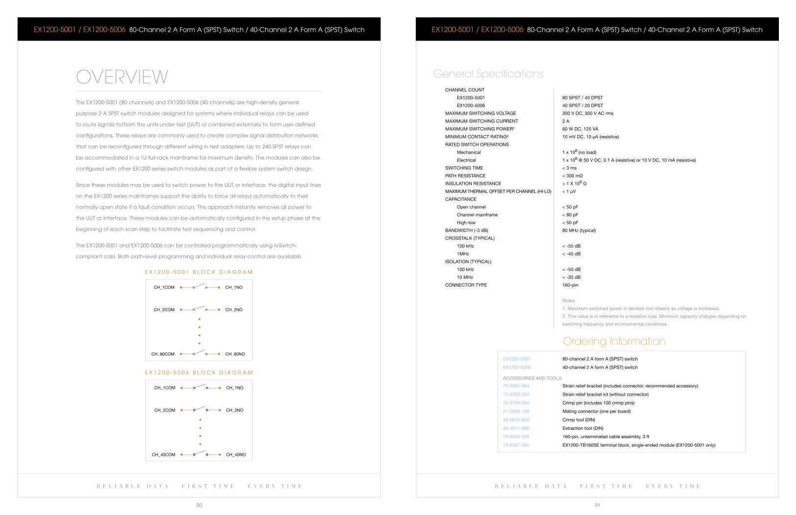
r e l i a b l e d a t a f i r s t t i m e e v e r y t i m e r e l i a b l e d a t a f i r s t t i m e e v e r y t i m e
90 91
eX1200-5001 / eX1200-5006 80-Channel2AFormA(SPST)Switch/40-Channel2AFormA(SPST)Switch
CHannel COUnT
eX1200-5001 80 sPsT / 40 DPsT
eX1200-5006 40 sPsT / 20 DPsT
MaXiMUM sWiTCHing VOlTage 300 V DC, 300 V aC rms
MaXiMUM sWiTCHing CUrrenT 2 a
MaXiMUM sWiTCHing POWer¹ 60 W DC, 125 Va
MiniMUM COnTaCT raTing² 10 mV DC, 10 μa (resistive)
raTeD sWiTCH OPeraTiOns
Mechanical 1 x 10⁸ (no load)
electrical 1 x 10⁶ @ 50 V DC, 0.1 a (resistive) or 10 V DC, 10 ma (resistive)
sWiTCHing TiMe < 3 ms
PaTH resisTanCe < 300 mΩ
insUlaTiOn resisTanCe > 1 X 10⁹ Ω
MaXiMUM THerMal OffseT Per CHannel (Hi-lO) < 1 μV
CaPaCiTanCe
Open channel < 50 pf
Channel-mainframe < 80 pf
High-low < 50 pf
banDWiDTH (-3 db) 80 MHz (typical)
CrOssTalk (TyPiCal)
100 kHz < -55 db
1MHz < -45 db
isOlaTiOn (TyPiCal)
100 kHz < -50 db
10 MHz < -35 db
COnneCTOr TyPe 160-pin
notes:
1. Maximum switched power is derated non-linearly as voltage is increased.
2. This value is in reference to a resistive load. Minimum capacity changes depending on
switching frequency and environmental conditions.
General Specifications
Ordering InformationeX1200-5001
eX1200-5006
80-channel 2 a form a (sPsT) switch
40-channel 2 a form a (sPsT) switch
70-0363-504
70-0363-503
52-0109-000
27-0088-160
46-0010-000
46-0011-000
70-0363-505
70-0367-005
strain relief bracket (includes connector, recommended accessory)
strain relief bracket kit (without connector)
Crimp pin (includes 100 crimp pins)
Mating connector (one per board)
Crimp tool (Din)
extraction tool (Din)
160-pin, unterminated cable assembly, 3 ft
eX1200-Tb160se terminal block, single-ended module (eX1200-5001 only)
aCCessOries anD TOOls
eX1200-5001 / eX1200-5006 80-Channel2AFormA(SPST)Switch/40-Channel2AFormA(SPST)Switch
OVERVIEWTheEX1200-5001(80channels)andEX1200-5006(40channels)arehigh-densitygeneral
purpose 2 a SPST switch modules designed for systems where individual relays can be used
to route signals to/from the units under test (UUT) or combined externally to form user-defined
configurations. These relays are commonly used to create complex signal distribution networks
that can be reconfigured through different wiring in test adapters. Up to 240 SPST relays can
be accommodated in a 1U full-rack mainframe for maximum density. The modules can also be
configured with other eX1200 series switch modules as part of a flexible system switch design.
Since these modules may be used to switch power to the UUT or interface, the digital input lines
on the eX1200 series mainframes support the ability to force all relays automatically to their
normally open state if a fault condition occurs. This approach instantly removes all power to
the UUT or interface. These modules can be automatically configured in the setup phase at the
beginning of each scan step to facilitate test sequencing and control.
The eX1200-5001 and eX1200-5006 can be controlled programmatically using IviSwtch-
compliant calls. both path-level programming and individual relay control are available.
CH_1NOCH_1COM
CH_2NOCH_2COM
CH_80NOCH_80COM
e X 1 2 0 0 - 5 0 0 1 b l O c k D I a G R a M
CH_1COM CH_1NO
CH_2COM CH_2NO
CH_40COM CH_40NO
e X 1 2 0 0 - 5 0 0 6 b l O c k D I a G R a M
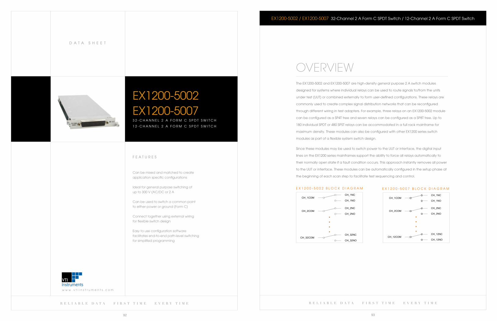
r e l i a b l e d a t a f i r s t t i m e e v e r y t i m e
93
w w w . v t i i n s t r u m e n t s . c o m
D a T a S H e e T
r e l i a b l e d a t a f i r s t t i m e e v e r y t i m e
92
eX1200-5002 / eX1200-5007 32-channel 2 a Form c SPDT Switch / 12-channel 2 a Form c SPDT Switch
OVERVIEWThe eX1200-5002 and eX1200-5007 are high-density general purpose 2 a switch modules
designed for systems where individual relays can be used to route signals to/from the units
under test (UUT) or combined externally to form user-defined configurations. These relays are
commonly used to create complex signal distribution networks that can be reconfigured
through different wiring in test adapters. For example, three relays on an eX1200-5002 module
canbeconfiguredasaSP4TtreeandsevenrelayscanbeconfiguredasaSP8Ttree.Upto
180individualSPDTor480SPSTrelayscanbeaccommodatedinafullrackmainframefor
maximum density. These modules can also be configured with other eX1200 series switch
modules as part of a flexible system switch design.
Since these modules may be used to switch power to the UUT or interface, the digital input
lines on the eX1200 series mainframes support the ability to force all relays automatically to
their normally open state if a fault condition occurs. This approach instantly removes all power
to the UUT or interface. These modules can be automatically configured in the setup phase at
the beginning of each scan step to facilitate test sequencing and control.
CH_1NOCH_1COM
CH_1NC
CH_2NOCH_2COM
CH_2NC
CH_32NO CH_32COM
CH_32NC
e X 1 2 0 0 - 5 0 0 2 b l O c k D I a G R a M
CH_1NOCH_1COM
CH_1NC
CH_2NOCH_2COM
CH_2NC
CH_12NO CH_12COM
CH_12NC
e X 1 2 0 0 - 5 0 0 7 b l O c k D I a G R a M
F e a T U R e S
can be mixed and matched to create
application specific configurations
Ideal for general purpose switching of
up to 300 V (ac/Dc or 2 a
can be used to switch a common point
to either power or ground (Form c)
connect together using external wiring
for flexible switch design
easy to use configuration software
facilitates end-to-end path-level switching
for simplified programming
eX1200-5002eX1200-50073 2 - c H a N N e l 2 a F O R M c S P D T S w I T c H
1 2 - c H a N N e l 2 a F O R M c S P D T S w I T c H
w w w . v t i i n s t r u m e n t s . c o m
D a T a S H e e T
r e l i a b l e d a t a f i r s t t i m e e v e r y t i m e
95
r e l i a b l e d a t a f i r s t t i m e e v e r y t i m e
94
F e a T U R e S
Integral shield attenuates noise and
crosstalk between adjacent channels/modules
Up to 192 individual SPDT relays in a 1U
full-rack mainframe
Ideal for hot switching general purpose
signals up to 5 a
Fail-safe interrupt forces relays open in case
of external fault condition
IVIswitch compliant drivers faciliate path
level commands to simplify programming
Mix/match with RF and/or highdensity multiplexers
for a flexible switching subsystem in a small footprint
eX1200-50043 2 - c H a N N e l 5 a S P D T S w I T c H
eX1200-5002 / eX1200-5007 32-channel 2 a Form c SPDT Switch / 12-channel 2 a Form c SPDT Switch
CHannel COUnT
eX1200-5002 32 sPDT
eX1200-5007 12 sPDT
MaXiMUM sWiTCHing VOlTage 300 V DC, 300 V aC rms
MaXiMUM sWiTCHing CUrrenT 2 a
MaXiMUM sWiTCHing POWer¹ 60 W DC, 125 Va
MiniMyM COnTaCT raTing² 10 mV DC, 10 μa (resistive)
raTeD sWiTCH OPeraTiOns
Mechanical 1 x 10⁸ (no load)
electrical 1 x 10⁶ @ 50 V DC, 0.1 a (resistive) or 10 V DC, 10 ma (resistive)
sWiTCHing TiMe < 3 ms
PaTH resisTanCe < 300 mΩ
insUlaTiOn resisTanCe > 1 X 10⁹ Ω
MaXiMUM THerMal OffseT Per CHannel (Hi-lO) < 1 μV
CaPaCiTanCe
eX1200-5002
Open channel < 50 pf
Channel-mainframe < 250 pf
High-low < 120 pf
eX1200-5007
Open channel < 50 pf
Channel-mainframe < 80 pf
High-low < 50 pf
banDWiDTH (-3 db)
eX1200-5002 40 MHz (typical)
eX1200-5007 80 MHz (typical)
CrOssTalk (TyPiCal)
100 kHz < -80 db
1MHz < -60 db
isOlaTiOn (TyPiCal)
100 kHz < -50 db
10 MHz < -45 db
COnneCTOr TyPe 104-pin
notes:
1. Maximum switched power is derated non-linearly as voltage is increased.
2. This value is in reference to a resistive load. Minimum capacity changes depending on
switching frequency and environmental conditions.
General Specifications
Ordering InformationeX1200-5002
eX1200-5007
32-channel 300 V/2 a sPDT switch
12-channel 300 V/2 a sPDT switch
70-0363-501
27-0389-104
27-0390-104
70-0297-001
70-0367-003
104-pin HD D-sub mating connector and backshell, with 3 ft unterminated 22 aWg wire
104-pin HD D-sub mating connector with hood and pins, fixed contacts (no crimp tool required)
104-pin HD D-sub mating connector, backshell and pins, crimp style
Crimp tooling, includes handle and positioner, 22 aWg
eX1200-Tb104se, single-ended module (eX1200-5002 only)
aCCessOries anD TOOls
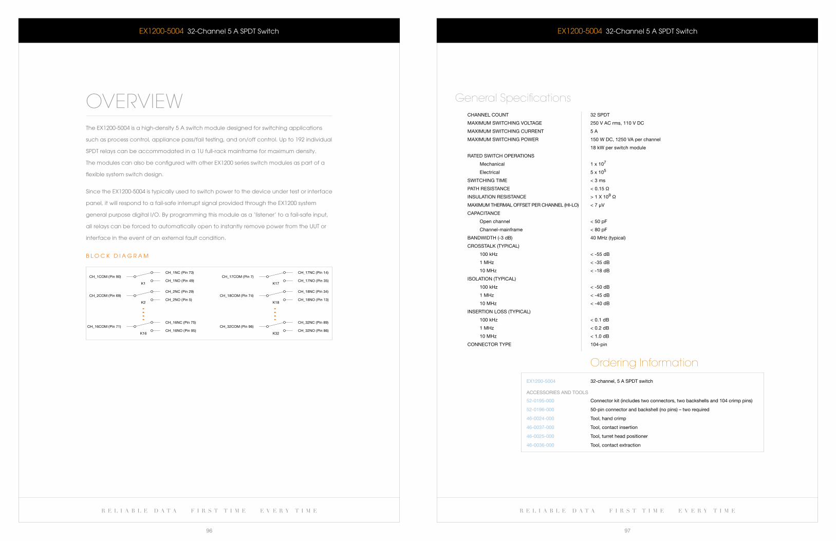
r e l i a b l e d a t a f i r s t t i m e e v e r y t i m e r e l i a b l e d a t a f i r s t t i m e e v e r y t i m e
96 97
eX1200-5004 32-channel 5 a SPDT Switch
CHannel COUnT 32 sPDT
MaXiMUM sWiTCHing VOlTage 250 V aC rms, 110 V DC
MaXiMUM sWiTCHing CUrrenT 5 a
MaXiMUM sWiTCHing POWer 150 W DC, 1250 Va per channel
18 kW per switch module
raTeD sWiTCH OPeraTiOns
Mechanical 1 x 10⁷
electrical 5 x 10⁵
sWiTCHing TiMe < 3 ms
PaTH resisTanCe < 0.15 Ω
insUlaTiOn resisTanCe > 1 X 10⁹ Ω
MaXiMUM THerMal OffseT Per CHannel (Hi-lO) < 7 μV
CaPaCiTanCe
Open channel < 50 pf
Channel-mainframe < 80 pf
banDWiDTH (-3 db) 40 MHz (typical)
CrOssTalk (TyPiCal)
100 kHz < -55 db
1 MHz < -35 db
10 MHz < -18 db
isOlaTiOn (TyPiCal)
100 kHz < -50 db
1 MHz < -45 db
10 MHz < -40 db
inserTiOn lOss (TyPiCal)
100 kHz < 0.1 db
1 MHz < 0.2 db
10 MHz < 1.0 db
COnneCTOr TyPe 104-pin
General Specifications
Ordering InformationeX1200-5004 32-channel, 5 a sPDT switch
52-0195-000
52-0196-000
46-0024-000
46-0037-000
46-0025-000
46-0036-000
Connector kit (includes two connectors, two backshells and 104 crimp pins)
50-pin connector and backshell (no pins) – two required
Tool, hand crimp
Tool, contact insertion
Tool, turret head positioner
Tool, contact extraction
aCCessOries anD TOOls
eX1200-5004 32-channel 5 a SPDT Switch
OVERVIEWThe eX1200-5004 is a high-density 5 a switch module designed for switching applications
such as process control, appliance pass/fail testing, and on/off control. Up to 192 individual
SPDT relays can be accommodated in a 1U full-rack mainframe for maximum density.
The modules can also be configured with other eX1200 series switch modules as part of a
flexible system switch design.
Since the eX1200-5004 is typically used to switch power to the device under test or interface
panel, it will respond to a fail-safe interrupt signal provided through the eX1200 system
general purpose digital I/O. by programming this module as a ‘listener’ to a fail-safe input,
all relays can be forced to automatically open to instantly remove power from the UUT or
interface in the event of an external fault condition.
CH_1NO (Pin 49)CH_1COM (Pin 90)
CH_1NC (Pin 73)
K1
CH_2NO (Pin 5)CH_2COM (Pin 69)
CH_2NC (Pin 29)
K2
CH_16NO (Pin 95)CH_16COM (Pin 71)
CH_16NC (Pin 75)
K16
K17
K18
K32
CH_17NO (Pin 35)CH_17COM (Pin 7)
CH_17NC (Pin 14)
CH_18NO (Pin 13)CH_18COM (Pin 74)
CH_18NC (Pin 34)
CH_32NO (Pin 86)CH_32COM (Pin 96)
CH_32NC (Pin 89)
b l O c k D I a G R a M

r e l i a b l e d a t a f i r s t t i m e e v e r y t i m e
99
w w w . v t i i n s t r u m e n t s . c o m
D a T a S H e e T
r e l i a b l e d a t a f i r s t t i m e e v e r y t i m e
98
eX1200-6101 / eX1200-6111 10-channel SP4T 1.3 GHz coaxial Switch / 5-channel SP4T 1.3 GHz coaxial Switch
OVERVIEWThe eX1200-6101 (10 channels) and eX1200-6111 (5 channels) are high-density SP4T RF switch
modules with ten individual SP4T coaxial trees that are isolated from each other and system
grounds to provide a high-fidelity switch path for switching signals in excess of 1.3 GHz. excellent
crosstalk and isolation is maintained by using very short low-loss coaxial runs from the connector
directly to the relays. all modules are also configured to avoid any unterminated stub effects,
improving overall signal integrity and allowing for high frequency matrix designs and large
multiplexer configurations while preserving bandwidth and maintaining low VSwR. The front panel
utilizes two high-density, 26-pin coaxial connectors designed for high reliability and low insertion loss.
Six of the modules can be accommodated in a 1U eX1200 full rack mainframe to provide a very
flexible RF switch network. For example, a single module can be configured through external
cabling to provide dual 1 x 16 multiplexers into two channels of a scope, or as a single 4 x 4 RF
matrix. The modules can also be combined with other eX1200 switch cards to configure a general
purpose subsystem to switch Dc to > 1.3 GHz.
The eX1200-6101 and eX1200-6111 can be controlled programmatically using IVI-Switch compliant
calls. both path level programming and individual relay control are available. both single-wire and
two-wire programming modes are available.
CH10_NO1
CH10_COM
CH10_NC
CH10_NO3
CH10_NO2
CH1_NO1
CH1_COM
CH1_NC
CH1_NO3
CH1_NO2
e X 1 2 0 0 - 6 1 0 1 b l O c k D I a G R a M
CH5_COM
CH5_NC
CH5_NO1
CH5_NO2
CH5_NO3
CH1_NO1
CH1_COM
CH1_NC
CH1_NO3
CH1_NO2
e X 1 2 0 0 - 6 1 1 1 b l O c k D I a G R a M
F e a T U R e S
Highest density RF switches and matrices
50 w maximum switching power
can be mixed and matched to create application specific
configurations
Ideal for general purpose RF switching with high signal
fidelity and total system bandwidths > 1 GHz
No unterminated stub effects
excellent crosstalk and isolation specifications
eX1200-6101eX1200-61111 0 - c H a N N e l S P 4 T 1 . 3 G H z c O a X I a l S w I T c H
5 - c H a N N e l S P 4 T 1 . 3 G H z c O a X I a l S w I T c H
w w w . v t i i n s t r u m e n t s . c o m
D a T a S H e e T
r e l i a b l e d a t a f i r s t t i m e e v e r y t i m e
101
r e l i a b l e d a t a f i r s t t i m e e v e r y t i m e
100
F e a T U R e S
Highest density RF switches and matrices
50 w maximum switching power
can be mixed and matched to create application
specific configurations
Ideal for general purpose RF switching with high
signal fidelity and total system bandwidths > 1 GHz
No unterminated stub effects
excellent crosstalk and isolation specifications
eX1200-61021 7 - c H a N N e l ( 1 X 2 ) c O a X I a l S w I T c H
eX1200-6101 / eX1200-6111 10-channel SP4T 1.3 GHz coaxial Switch / 5-channel SP4T 1.3 GHz coaxial Switch
CHannel COUnT
eX1200-6101 10 sP4T multiplexers
eX1200-6111 5 sP4T multiplexers
relay TyPe electromechanical, fail-safe
MaXiMUM sWiTCHing VOlTage 220 V DC, 250 V aC rms
MaXiMUM sWiTCHing CUrrenT 2 a
MaXiMUM sWiTCHing POWer 50 W, 62.5 Va
raTeD sWiTCH OPeraTiOns
Mechanical 5 x 10⁶
electrical 1 x 10⁵ at full load
sWiTCHing TiMe < 5 ms
PaTH resisTanCe < 0.250 Ω
insUlaTiOn resisTanCe > 1 X 10⁹ Ω
banDWiDTH (-3 db) 1.3 gHz (typical)
inserTiOn lOss (TyPiCal)
500 MHz < 0.9 db
1.3 gHz < 3.0 db
CrOssTalk (TyPiCal)
500 MHz < -70 db
1.3 gHz < -60 db
isOlaTiOn (TyPiCal)
500 MHz < -70 db
1.3 gHz < -60 db
VsWr (TyPiCal)
500 MHz < 1.11:1
1.3 gHz < 2.92:1
COnneCTOr TyPe Dual 26-pin
General Specifications
Ordering InformationeX1200-6101
eX1200-6111
10-channel sP4T 1.3 gHz coaxial switch
5-channel sP4T 1.3 gHz coaxial switch
70-0150-000
70-0149-000
70-0149-001
46-0018-000
46-0018-001
46-0021-000
26-pin mating connector and housing (2 required)
10-pin/ferrule kit (rg 316 50 Ω)
10-pin/ferrule kit (rg 178 50 Ω)
Crimp tool, coax rg316 (50 Ω)
Crimp tool, coax rg178 (50 Ω)
Tool, pin extractor, size 16 contact, aMP M series
aCCessOries anD TOOls
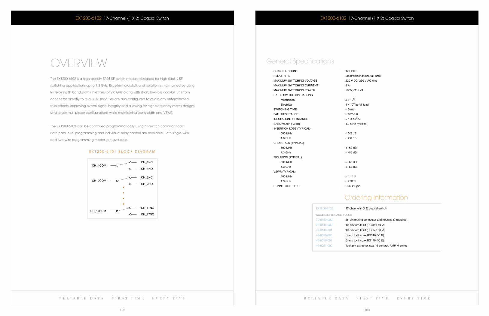
r e l i a b l e d a t a f i r s t t i m e e v e r y t i m e r e l i a b l e d a t a f i r s t t i m e e v e r y t i m e
102 103
eX1200-6102 17-channel (1 X 2) coaxial Switch
CHannel COUnT 17 sPDT
relay TyPe electromechanical, fail-safe
MaXiMUM sWiTCHing VOlTage 220 V DC, 250 V aC rms
MaXiMUM sWiTCHing CUrrenT 2 a
MaXiMUM sWiTCHing POWer 50 W, 62.5 Va
raTeD sWiTCH OPeraTiOns
Mechanical 5 x 10⁶
electrical 1 x 10⁵ at full load
sWiTCHing TiMe < 5 ms
PaTH resisTanCe < 0.250 Ω
insUlaTiOn resisTanCe > 1 X 10⁹ Ω
banDWiDTH (-3 db) 1.3 gHz (typical)
inserTiOn lOss (TyPiCal)
500 MHz < 0.2 db
1.3 gHz < 2.0 db
CrOssTalk (TyPiCal)
500 MHz < -60 db
1.3 gHz < -55 db
isOlaTiOn (TyPiCal)
500 MHz < -65 db
1.3 gHz < -55 db
VsWr (TyPiCal)
500 MHz < 1.11:1
1.3 gHz < 2.92:1
COnneCTOr TyPe Dual 26-pin
General Specifications
Ordering InformationeX1200-6102 17-channel (1 X 2) coaxial switch
70-0150-000
70-0149-000
70-0149-001
46-0018-000
46-0018-001
46-0021-000
26-pin mating connector and housing (2 required)
10-pin/ferrule kit (rg 316 50 Ω)
10-pin/ferrule kit (rg 178 50 Ω)
Crimp tool, coax rg316 (50 Ω)
Crimp tool, coax rg178 (50 Ω)
Tool, pin extractor, size 16 contact, aMP M series
aCCessOries anD TOOls
eX1200-6102 17-channel (1 X 2) coaxial Switch
OVERVIEWThe eX1200-6102 is a high-density SPDT RF switch module designed for high-fidelity RF
switching applications up to 1.3 GHz. excellent crosstalk and isolation is maintained by using
RF relays with bandwidths in excess of 2.0 GHz along with short, low-loss coaxial runs from
connector directly to relays. all modules are also configured to avoid any unterminated
stub effects, improving overall signal integrity and allowing for high frequency matrix designs
and larger multiplexer configurations while maintaining bandwidth and VSwR.
The eX1200-6102 can be controlled programmatically using IVI-Switch compliant calls.
both path level programming and individual relay control are available. both single-wire
and two-wire programming modes are available.
CH_1NOCH_1COM
CH_1NC
CH_2NOCH_2COM
CH_2NC
CH_17COMCH_17NC
CH_17NO
e X 1 2 0 0 - 6 1 0 1 b l O c k D I a G R a M
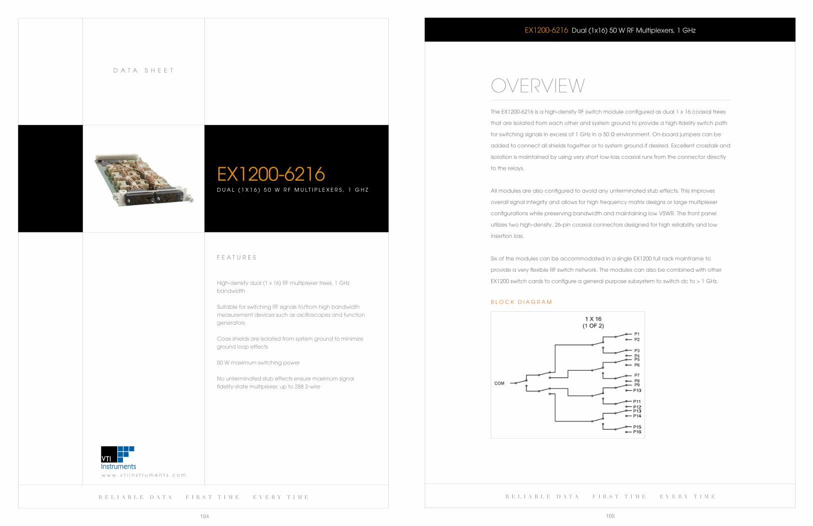
r e l i a b l e d a t a f i r s t t i m e e v e r y t i m e
105
w w w . v t i i n s t r u m e n t s . c o m
D a T a S H e e T
r e l i a b l e d a t a f i r s t t i m e e v e r y t i m e
104
eX1200-6216 Dual (1x16) 50 w RF Multiplexers, 1 GHz
OVERVIEWThe eX1200-6216 is a high-density RF switch module configured as dual 1 x 16 coaxial trees
that are isolated from each other and system ground to provide a high-fidelity switch path
for switching signals in excess of 1 GHz in a 50 Ω environment. On-board jumpers can be
added to connect all shields together or to system ground if desired. excellent crosstalk and
isolation is maintained by using very short low-loss coaxial runs from the connector directly
to the relays.
all modules are also configured to avoid any unterminated stub effects. This improves
overall signal integrity and allows for high frequency matrix designs or large multiplexer
configurations while preserving bandwidth and maintaining low VSwR. The front panel
utilizes two high-density, 26-pin coaxial connectors designed for high reliability and low
insertion loss.
Six of the modules can be accommodated in a single eX1200 full rack mainframe to
provide a very flexible RF switch network. The modules can also be combined with other
eX1200 switch cards to configure a general purpose subsystem to switch dc to > 1 GHz.
b l O c k D I a G R a M
F e a T U R e S
High-density dual (1 x 16) RF multiplexer trees, 1 GHz
bandwidth
Suitable for switching RF signals to/from high bandwidth
measurement devices such as oscilloscopes and function
generators
coax shields are isolated from system ground to minimize
ground loop effects
50 w maximum switching power
No unterminated stub effects ensure maximum signal
fidelity-statemultiplexer,upto2882-wire
eX1200-6216D U a l ( 1 X 1 6 ) 5 0 w R F M U l T I P l e X e R S , 1 G H z

w w w . v t i i n s t r u m e n t s . c o m
D a T a S H e e T
r e l i a b l e d a t a f i r s t t i m e e v e r y t i m e
107
r e l i a b l e d a t a f i r s t t i m e e v e r y t i m e
106
F e a T U R e S
Greater than 250 MHz bandwidth
Very high-density (two 1x16 muxes)
500 V switching capability
Ideal for differential coaxial switching
Star configurations allow any channel to be
connected to any other channel
eX1200-6216HVD U a l ( 1 X 1 6 ) 2 5 0 M H z , 5 0 0 V M U l T I P l e X e R
eX1200-6216 Dual (1x16) 50 w RF Multiplexers, 1 GHz
CHannel COUnT Dual (1 x 16) 50 Ω rf multiplexers, 1 gHz
relay TyPe electromechanical, fail-safe
MaXiMUM sWiTCHing VOlTage 220 V DC, 250 V aC rms
MaXiMUM sWiTCHing CUrrenT 2 a
MaXiMUM sWiTCHing POWer 50 W, 62.5 Va
raTeD sWiTCH OPeraTiOns
Mechanical 5 x 10⁶
electrical 1 x 10⁵ at full load
sWiTCHing TiMe < 5 ms
PaTH resisTanCe < 500 mΩ
insUlaTiOn resisTanCe > 1 X 10⁹ Ω
banDWiDTH (-3 db) 1 gHz (typical)
inserTiOn lOss (TyPiCal)
500 MHz < 1.0 db
1.3 gHz < 3.0 db
CrOssTalk (TyPiCal)
500 MHz < -75 db
1.3 gHz < -70 db
isOlaTiOn (TyPiCal)
500 MHz < -75 db
1.3 gHz < -70 db
VsWr (TyPiCal)
500 MHz < 1.4:1
1.3 gHz < 2.5:1
COnneCTOr TyPe Dual 26-pin
General Specifications
Ordering InformationeX1200-6216 Dual (1x16) 50 W rf multiplexers, 1 gHz
70-0150-000
70-0149-000
70-0149-001
46-0018-000
46-0018-001
46-0021-000
26-pin mating connector and housing (2 required)
10-pin/ferrule kit (rg 316 50 Ω)
10-pin/ferrule kit (rg 178 50 Ω)
Crimp tool, coax rg316 (50 Ω)
Crimp tool, coax rg178 (50 Ω)
Tool, pin extractor, size 16 contact, aMP M series
aCCessOries anD TOOls
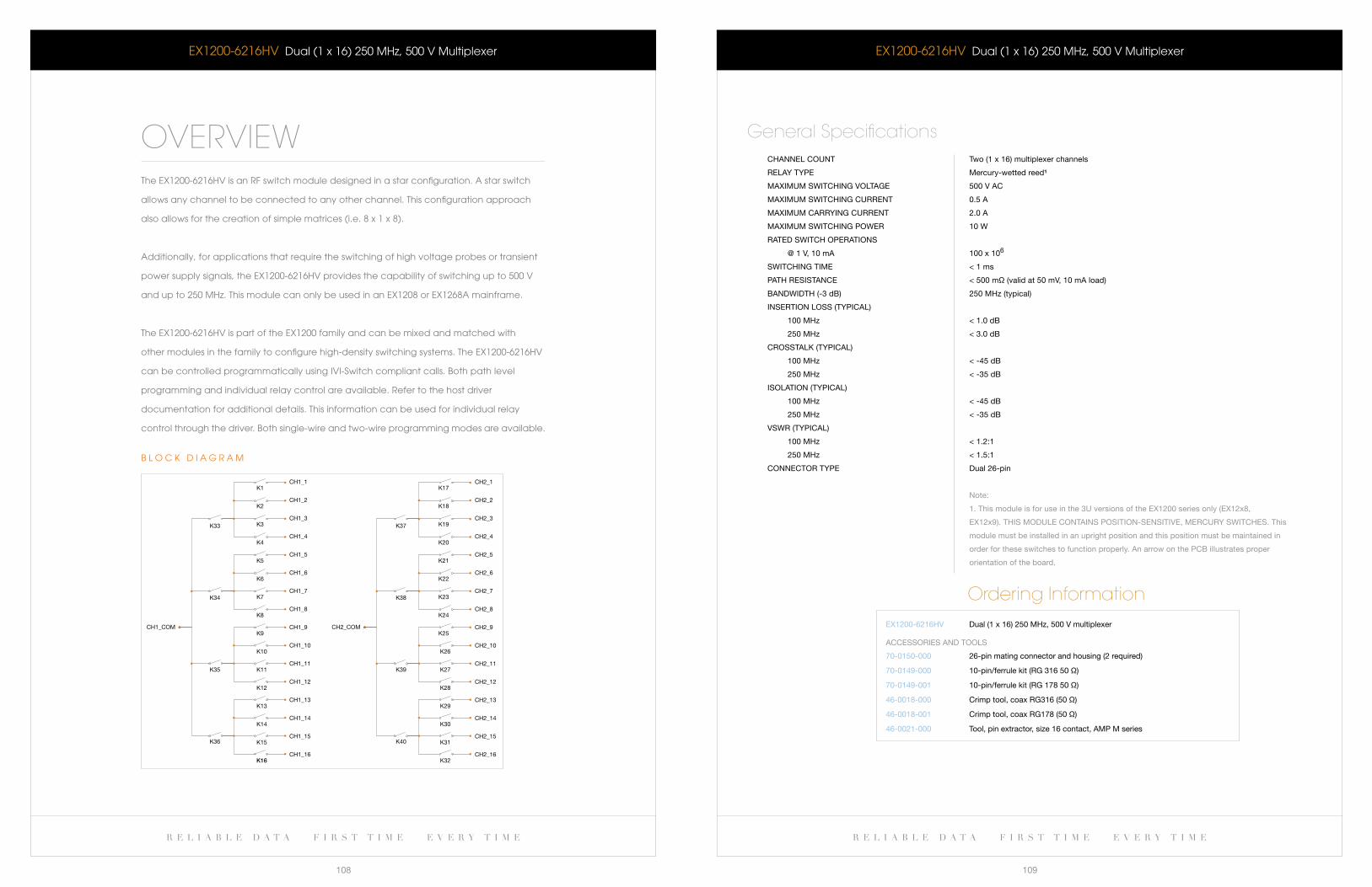
r e l i a b l e d a t a f i r s t t i m e e v e r y t i m e r e l i a b l e d a t a f i r s t t i m e e v e r y t i m e
108 109
eX1200-6216HV Dual (1 x 16) 250 MHz, 500 V Multiplexer
CHannel COUnT Two (1 x 16) multiplexer channels
relay TyPe Mercury-wetted reed¹
MaXiMUM sWiTCHing VOlTage 500 V aC
MaXiMUM sWiTCHing CUrrenT 0.5 a
MaXiMUM Carrying CUrrenT 2.0 a
MaXiMUM sWiTCHing POWer 10 W
raTeD sWiTCH OPeraTiOns
@ 1 V, 10 ma 100 x 106
sWiTCHing TiMe < 1 ms
PaTH resisTanCe < 500 mΩ (valid at 50 mV, 10 ma load)
banDWiDTH (-3 db) 250 MHz (typical)
inserTiOn lOss (TyPiCal)
100 MHz < 1.0 db
250 MHz < 3.0 db
CrOssTalk (TyPiCal)
100 MHz < -45 db
250 MHz < -35 db
isOlaTiOn (TyPiCal)
100 MHz < -45 db
250 MHz < -35 db
VsWr (TyPiCal)
100 MHz < 1.2:1
250 MHz < 1.5:1
COnneCTOr TyPe Dual 26-pin
note:
1. This module is for use in the 3U versions of the eX1200 series only (eX12x8,
eX12x9). THis MODUle COnTains POsiTiOn-sensiTiVe, MerCUry sWiTCHes. This
module must be installed in an upright position and this position must be maintained in
order for these switches to function properly. an arrow on the PCb illustrates proper
orientation of the board.
General Specifications
Ordering InformationeX1200-6216HV Dual (1 x 16) 250 MHz, 500 V multiplexer
70-0150-000
70-0149-000
70-0149-001
46-0018-000
46-0018-001
46-0021-000
26-pin mating connector and housing (2 required)
10-pin/ferrule kit (rg 316 50 Ω)
10-pin/ferrule kit (rg 178 50 Ω)
Crimp tool, coax rg316 (50 Ω)
Crimp tool, coax rg178 (50 Ω)
Tool, pin extractor, size 16 contact, aMP M series
aCCessOries anD TOOls
eX1200-6216HV Dual (1 x 16) 250 MHz, 500 V Multiplexer
OVERVIEWThe eX1200-6216HV is an RF switch module designed in a star configuration. a star switch
allows any channel to be connected to any other channel. This configuration approach
alsoallowsforthecreationofsimplematrices(i.e.8x1x8).
additionally, for applications that require the switching of high voltage probes or transient
power supply signals, the eX1200-6216HV provides the capability of switching up to 500 V
andupto250MHz.ThismodulecanonlybeusedinanEX1208orEX1268Amainframe.
The eX1200-6216HV is part of the eX1200 family and can be mixed and matched with
other modules in the family to configure high-density switching systems. The eX1200-6216HV
can be controlled programmatically using IVI-Switch compliant calls. both path level
programming and individual relay control are available. Refer to the host driver
documentation for additional details. This information can be used for individual relay
control through the driver. both single-wire and two-wire programming modes are available.
CH1_COM CH2_COM
K33
K1
K2
K3
K4
K5
K6
K7
K8
K9
K10
K11
K12
K13
K14
K15
K16
K17
K18
K19
K20
K21
K22
K23
K24
K25
K26
K27
K28
K29
K30
K31
K32
CH1_1
CH1_2
CH1_3
CH1_4
CH1_5
CH1_6
CH1_7
CH1_8
CH1_9
CH1_10
CH1_11
CH1_12
CH1_13
CH1_14
CH1_15
CH1_16
CH2_1
CH2_2
CH2_3
CH2_4
CH2_5
CH2_6
CH2_7
CH2_8
CH2_9
CH2_10
CH2_11
CH2_12
CH2_13
CH2_14
CH2_15
CH2_16
K34
K35
K36
K37
K38
K39
K40
b l O c k D I a G R a M
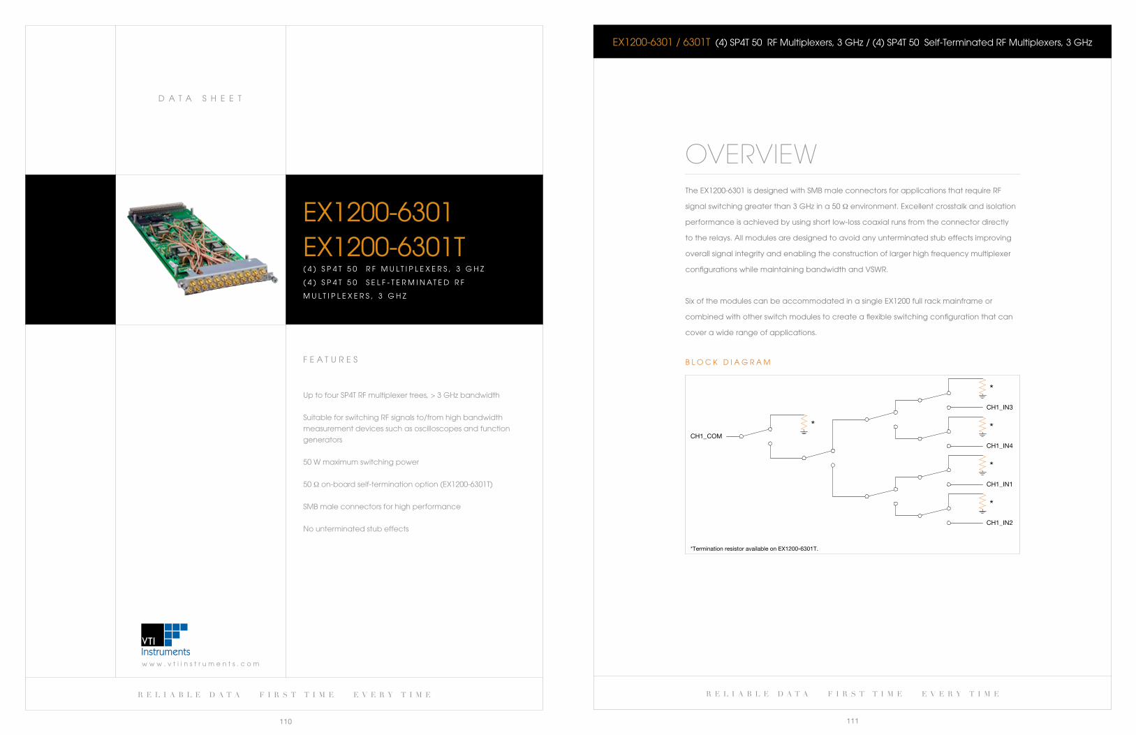
r e l i a b l e d a t a f i r s t t i m e e v e r y t i m e
111
w w w . v t i i n s t r u m e n t s . c o m
D a T a S H e e T
r e l i a b l e d a t a f i r s t t i m e e v e r y t i m e
110
eX1200-6301 / 6301T (4) SP4T 50 RF Multiplexers, 3 GHz / (4) SP4T 50 Self-Terminated RF Multiplexers, 3 GHz
OVERVIEWThe eX1200-6301 is designed with SMb male connectors for applications that require RF
signal switching greater than 3 GHz in a 50 Ω environment. excellent crosstalk and isolation
performance is achieved by using short low-loss coaxial runs from the connector directly
to the relays. all modules are designed to avoid any unterminated stub effects improving
overall signal integrity and enabling the construction of larger high frequency multiplexer
configurations while maintaining bandwidth and VSwR.
Six of the modules can be accommodated in a single eX1200 full rack mainframe or
combined with other switch modules to create a flexible switching configuration that can
cover a wide range of applications.
CH
*Termination resistor available on EX1200-6301T.
1_COM
*
*
CH1_IN3
*
CH1_IN4
*
CH1_IN1
*
CH1_IN2
b l O c k D I a G R a MF e a T U R e S
Up to four SP4T RF multiplexer trees, > 3 GHz bandwidth
Suitable for switching RF signals to/from high bandwidth
measurement devices such as oscilloscopes and function
generators
50 w maximum switching power
50 Ω on-board self-termination option (eX1200-6301T)
SMb male connectors for high performance
No unterminated stub effects
eX1200-6301eX1200-6301T( 4 ) S P 4 T 5 0 R F M U l T I P l e X e R S , 3 G H z
( 4 ) S P 4 T 5 0 S e l F - T e R M I N a T e D R F
M U l T I P l e X e R S , 3 G H z
w w w . v t i i n s t r u m e n t s . c o m
D a T a S H e e T
r e l i a b l e d a t a f i r s t t i m e e v e r y t i m e
113
r e l i a b l e d a t a f i r s t t i m e e v e r y t i m e
112
F e a T U R e S
22 square inches of real estate for user-defined designs
96 digital I/O lines configurable as input or output
Three power supply rails for custom designs
access to 12.5 MHz clock for complex designs
Multiple front panel connector options
IVI drivers simplify software development
Mix and match with standard eX1200 switching and
I/O modules to create high-density configurations
eX1200-7000P R O T O T Y P I N G c a R D F O R e X 1 2 0 0
eX1200-6301 / 6301T (4) SP4T 50 RF Multiplexers, 3 GHz / (4) SP4T 50 Self-Terminated RF Multiplexers, 3 GHz
CHannel COUnT
eX1200-6301 Dual (1 x 16) 50 Ω rf multiplexers, 3 gHz
eX1200-6301T quad (4 x 1) self-terminated multiplexer, 3 gHz
relay TyPe electromechanical, fail-safe
MaXiMUM sWiTCHing VOlTage 220 VDC, 250 VaC rms
MaXiMUM sWiTCHing CUrrenT 2 a
MaXiMUM sWiTCHing POWer 50 W
raTeD sWiTCH OPeraTiOns
Mechanical 5 x 10⁵
electrical 1 x 10⁵ (full load)
sWiTCHing TiMe < 5 ms
PaTH resisTanCe < 1 Ω
insUlaTiOn resisTanCe > 1 x 10⁹ Ω
banDWiDTH (-3 db) 3 gHz (typical)
inserTiOn lOss (TyPiCal)
1 gHz < 0.5 db
3 gHz < 3.0 db
CrOssTalk (TyPiCal)
1 gHz < -60 db
3 gHz < -55 db
isOlaTiOn (TyPiCal)
1 gHz < -65 db
3 gHz < -55 db
VsWr (TyPiCal)
1 gHz < 1.2:1
3 gHz < 1.5:1
General Specifications
Ordering InformationeX1200-6301
eX1200-6301T
(4) sP4T 50 Ω rf multiplexers, 3 gHz
(4) sP4T 50 Ω self-terminated rf multiplexers, 1.5 gHz
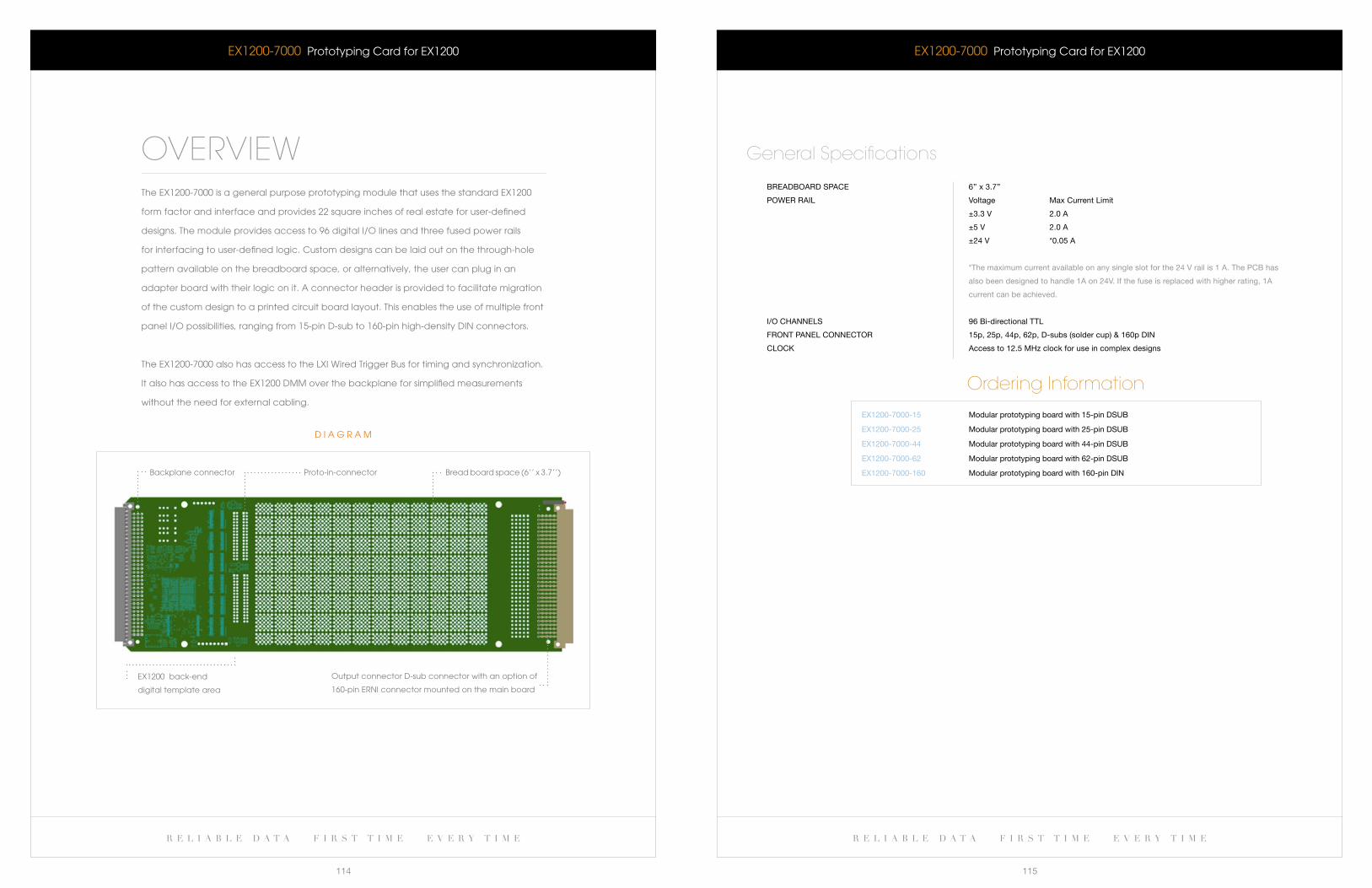
r e l i a b l e d a t a f i r s t t i m e e v e r y t i m e r e l i a b l e d a t a f i r s t t i m e e v e r y t i m e
114 115
eX1200-7000 Prototyping card for eX1200
breaDbOarD sPaCe 6’’ x 3.7’’
POWer rail Voltage Max Current limit
±3.3 V 2.0 a
±5 V 2.0 a
±24 V *0.05 a
*The maximum current available on any single slot for the 24 V rail is 1 a. The PCb has
also been designed to handle 1a on 24V. if the fuse is replaced with higher rating, 1a
current can be achieved.
i/O CHannels 96 bi-directional TTl
frOnT Panel COnneCTOr 15p, 25p, 44p, 62p, D-subs (solder cup) & 160p Din
ClOCk access to 12.5 MHz clock for use in complex designs
General Specifications
Ordering Information
eX1200-7000-15
eX1200-7000-25
eX1200-7000-44
eX1200-7000-62
eX1200-7000-160
Modular prototyping board with 15-pin DsUb
Modular prototyping board with 25-pin DsUb
Modular prototyping board with 44-pin DsUb
Modular prototyping board with 62-pin DsUb
Modular prototyping board with 160-pin Din
eX1200-7000 Prototyping card for eX1200
OVERVIEWThe eX1200-7000 is a general purpose prototyping module that uses the standard eX1200
form factor and interface and provides 22 square inches of real estate for user-defined
designs. The module provides access to 96 digital I/O lines and three fused power rails
for interfacing to user-defined logic. custom designs can be laid out on the through-hole
pattern available on the breadboard space, or alternatively, the user can plug in an
adapter board with their logic on it. a connector header is provided to facilitate migration
of the custom design to a printed circuit board layout. This enables the use of multiple front
panel I/O possibilities, ranging from 15-pin D-sub to 160-pin high-density DIN connectors.
The eX1200-7000 also has access to the lXI wired Trigger bus for timing and synchronization.
It also has access to the eX1200 DMM over the backplane for simplified measurements
without the need for external cabling.
D I a G R a M
backplane connector Proto-in-connector bread board space (6’’ x 3.7’’)
eX1200 back-end
digital template area
Output connector D-sub connector with an option of
160-pin eRNI connector mounted on the main board
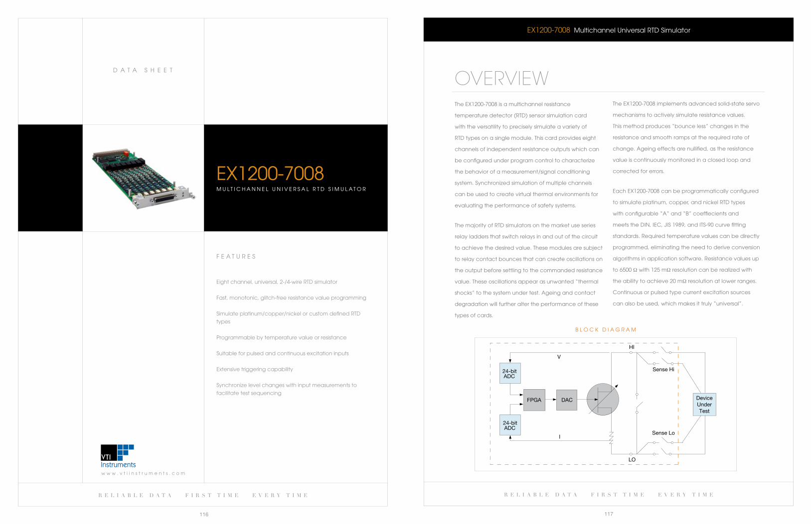
r e l i a b l e d a t a f i r s t t i m e e v e r y t i m e
117
w w w . v t i i n s t r u m e n t s . c o m
D a T a S H e e T
r e l i a b l e d a t a f i r s t t i m e e v e r y t i m e
116
EX1200-7008 Multichannel Universal RTD Simulator
OVERVIEWTheEX1200-7008isamultichannelresistance
temperature detector (RTD) sensor simulation card
with the versatility to precisely simulate a variety of
RTD types on a single module. This card provides eight
channels of independent resistance outputs which can
be configured under program control to characterize
the behavior of a measurement/signal conditioning
system. Synchronized simulation of multiple channels
can be used to create virtual thermal environments for
evaluating the performance of safety systems.
The majority of RTD simulators on the market use series
relay ladders that switch relays in and out of the circuit
to achieve the desired value. These modules are subject
to relay contact bounces that can create oscillations on
the output before settling to the commanded resistance
value. These oscillations appear as unwanted “thermal
shocks” to the system under test. ageing and contact
degradation will further alter the performance of these
types of cards.
24-bit ADC
FPGA
24-bit ADC
DAC
HI
Sense Hi
Sense Lo
LO
V
I
DeviceUnderTest
b l O c k D I a G R a M
TheEX1200-7008implementsadvancedsolid-stateservo
mechanisms to actively simulate resistance values.
This method produces “bounce less” changes in the
resistance and smooth ramps at the required rate of
change. ageing effects are nullified, as the resistance
value is continuously monitored in a closed loop and
corrected for errors.
EachEX1200-7008canbeprogrammaticallyconfigured
to simulate platinum, copper, and nickel RTD types
with configurable “a” and “b” coeffiecients and
meetstheDIN,IEC,JIS1989,andITS-90curvefitting
standards. Required temperature values can be directly
programmed, eliminating the need to derive conversion
algorithms in application software. Resistance values up
to 6500 Ω with 125 mΩ resolution can be realized with
the ability to achieve 20 mΩ resolution at lower ranges.
continuous or pulsed type current excitation sources
can also be used, which makes it truly “universal”.
F e a T U R e S
eight channel, universal, 2-/4-wire RTD simulator
Fast, monotonic, glitch-free resistance value programming
Simulate platinum/copper/nickel or custom defined RTD
types
Programmable by temperature value or resistance
Suitable for pulsed and continuous excitation inputs
extensive triggering capability
Synchronize level changes with input measurements to
facilitate test sequencing
EX1200-7008M U l T I c H a N N e l U N I V e R S a l R T D S I M U l a T O R
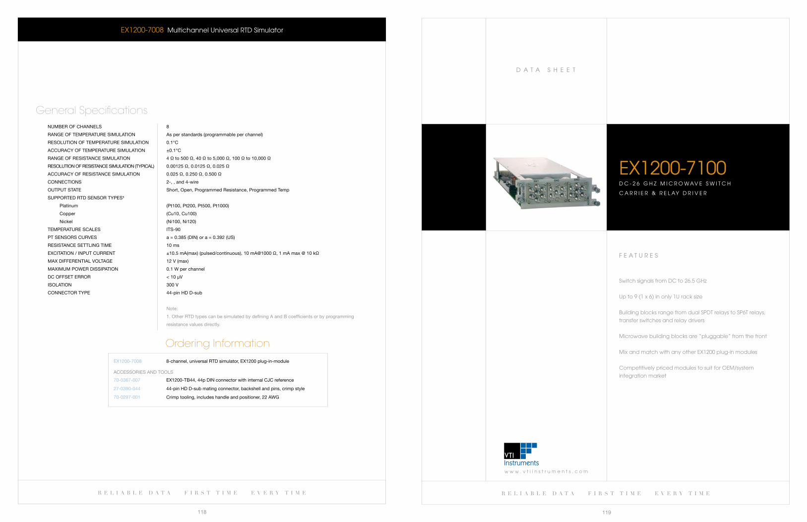
w w w . v t i i n s t r u m e n t s . c o m
D a T a S H e e T
r e l i a b l e d a t a f i r s t t i m e e v e r y t i m e
119
r e l i a b l e d a t a f i r s t t i m e e v e r y t i m e
118
F e a T U R e S
Switch signals from Dc to 26.5 GHz
Up to 9 (1 x 6) in only 1U rack size
building blocks range from dual SPDT relays to SP6T relays,
transfer switches and relay drivers
Microwave building blocks are “pluggable” from the front
Mix and match with any other eX1200 plug-in modules
competitively priced modules to suit for OeM/system
integration market
eX1200-7100D c - 2 6 G H z M I c R O w aV e S w I T c H
c a R R I e R & R e l aY D R I V e R
EX1200-7008 Multichannel Universal RTD Simulator
nUMber Of CHannels 8
range Of TeMPeraTUre siMUlaTiOn as per standards (programmable per channel)
resOlUTiOn Of TeMPeraTUre siMUlaTiOn 0.1°C
aCCUraCy Of TeMPeraTUre siMUlaTiOn ±0.1°C
range Of resisTanCe siMUlaTiOn 4 Ω to 500 Ω, 40 Ω to 5,000 Ω, 100 Ω to 10,000 Ω
resOlUTiOn Of resisTanCe siMUlaTiOn (TyPiCal) 0.00125 Ω, 0.0125 Ω, 0.025 Ω
aCCUraCy Of resisTanCe siMUlaTiOn 0.025 Ω, 0.250 Ω, 0.500 Ω
COnneCTiOns 2-, , and 4-wire
OUTPUT sTaTe short, Open, Programmed resistance, Programmed Temp
sUPPOrTeD rTD sensOr TyPes¹
Platinum (Pt100, Pt200, Pt500, Pt1000)
Copper (Cu10, Cu100)
nickel (ni100, ni120)
TeMPeraTUre sCales iTs-90
PT sensOrs CUrVes a = 0.385 (Din) or a = 0.392 (Us)
resisTanCe seTTling TiMe 10 ms
eXCiTaTiOn / inPUT CUrrenT ±10.5 ma(max) (pulsed/continuous), 10 ma@1000 Ω, 1 ma max @ 10 kΩ
MaX DifferenTial VOlTage 12 V (max)
MaXiMUM POWer DissiPaTiOn 0.1 W per channel
DC OffseT errOr < 10 μV
isOlaTiOn 300 V
COnneCTOr TyPe 44-pin HD D-sub
note:
1. Other rTD types can be simulated by defining a and b coefficients or by programming
resistance values directly.
General Specifications
Ordering InformationeX1200-7008 8-channel, universal rTD simulator, eX1200 plug-in-module
70-0367-007
27-0390-044
70-0297-001
eX1200-Tb44, 44p Din connector with internal CJC reference
44-pin HD D-sub mating connector, backshell and pins, crimp style
Crimp tooling, includes handle and positioner, 22 aWg
aCCessOries anD TOOls
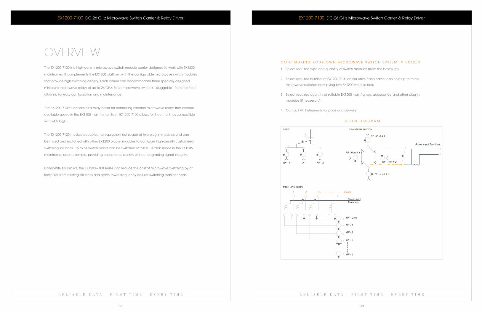
r e l i a b l e d a t a f i r s t t i m e e v e r y t i m e r e l i a b l e d a t a f i r s t t i m e e v e r y t i m e
120 121
RF - Port # 1
RF - Port # 2
RF - Port # 3
RF - Port # 4
TRANSFER SWITCH
Power Input Terminals
RF - 1
RF - 2
RF - 3
RF - 6
RF - Com
Power InputTerminals
1 2 3-- - -- - -- - -- - 6 com
MULTI-POSITION
RF - 1 ln RF - 2
SPDT
b l O c k D I a G R a M
eX1200-7100 Dc-26 GHz Microwave Switch carrier & Relay Driver
c O N F I G U R I N G Y O U R O w N M I c R O w aV e S w I T c H S Y S T e M I N e X 1 2 0 0
1. Select required type and quantity of switch modules (from the below list).
2. Select required number of eX1200-7100 carrier units. each carrier can hold up to three
microwave switches occupying two eX1200 module slots.
3. Select required quantity of suitable eX1200 mainframes, accessories, and other plug-in
modules (if necessary).
4. contact VTI Instruments for price and delivery.
eX1200-7100 Dc-26 GHz Microwave Switch carrier & Relay Driver
OVERVIEWThe eX1200-7100 is a high-density microwave switch module carrier designed to work with eX1200
mainframes. It complements the eX1200 platform with the configurable microwave switch modules
that provide high switching density. each carrier can accommodate three specially designed
miniature microwave relays of up to 26 GHz. each microwave switch is “pluggable” from the front
allowing for easy configuration and maintenance.
The eX1200-7100 functions as a relay driver for controlling external microwave relays that exceed
availablespaceintheEX1200mainframe.EachEX1200-7100allowsfor8controllinescompatible
with 24 V logic.
The eX1200-7100 module occupies the equivalent slot space of two plug-in-modules and can
be mixed and matched with other eX1200 plug-in modules to configure high-density customized
switching solutions. Up to 54 switch points can be switched within a 1U rack space in the eX1206
mainframe, as an example, providing exceptional density without degrading signal integrity.
competitively priced, the eX1200-7100 series can reduce the cost of microwave switching by at
least 20% from existing solutions and satisfy lower frequency cellular switching market needs.
w w w . v t i i n s t r u m e n t s . c o m
D a T a S H e e T
r e l i a b l e d a t a f i r s t t i m e e v e r y t i m e
123
r e l i a b l e d a t a f i r s t t i m e e v e r y t i m e
122
F e a T U R e S
Up to 96 differential channels per full rack mainframe
constantly monitor input signals for fault conditions
Flexible configurations for detecting edges, out-of-bounds
conditions and measuring pulse widths
Inputs can be masked, inverted, and combined to
produce interrupts
can be used as a time stamp module and as a digital I/O
Programmable debounce circuitry prevents erroneous
readings
10 V and 100 V input ranges
On-boardmemorystoreseventswithIEEE1588timestamps
Synchronize reading of input states with other scanned
analog channels
eX1200-74161 6 - c H a N N e l c O M P a R a T O R / e V e N T D e T e c T O R
eX1200-7100 Dc-26 GHz Microwave Switch carrier & Relay Driver
aVerage POWer Per CHannel 40 W @ 26.5 gHz
sWiTCHing TiMe < 15 ms
rf iMPeDanCe 50 Ω
isOlaTiOn (db Min)
DC-3 gHz 80 db
3-8 gHz 70 db
8-12.4 gHz 60 db
12.4-18 gHz 60 db
18-26.5 gHz 45 db
inserTiOn lOss (db MaX)
DC-3 gHz 0.2 db
3-8 gHz 0.3 db
8-12.4 gHz 0.4 db
12.4-18 gHz 0.5 db
18-26.5 gHz 0.7 db
VSWR MIn
DC-3 GHz 1.2:1
3-8 GHz 1.3:1
8-12.4 GHz 1.4:1
12.4-18 GHz 1.5:1
18-26.5 GHz 1.7:1
ConnECtoR typE SMA
General Specifications
Ordering Information
eX1200-7100
eX1200-7102
eX1200-7104
eX1200-7106
eX1200-7122
DC-26 gHz microwave switch carrier & relay driver
Dual (sPDT) 26.5 gHz relay (unterminated)
sP4T 26.5 gHz relay (unterminated)
sP6T 26.5 gHz relay (unterminated)
26.5 gHz transfer switch (unterminated)
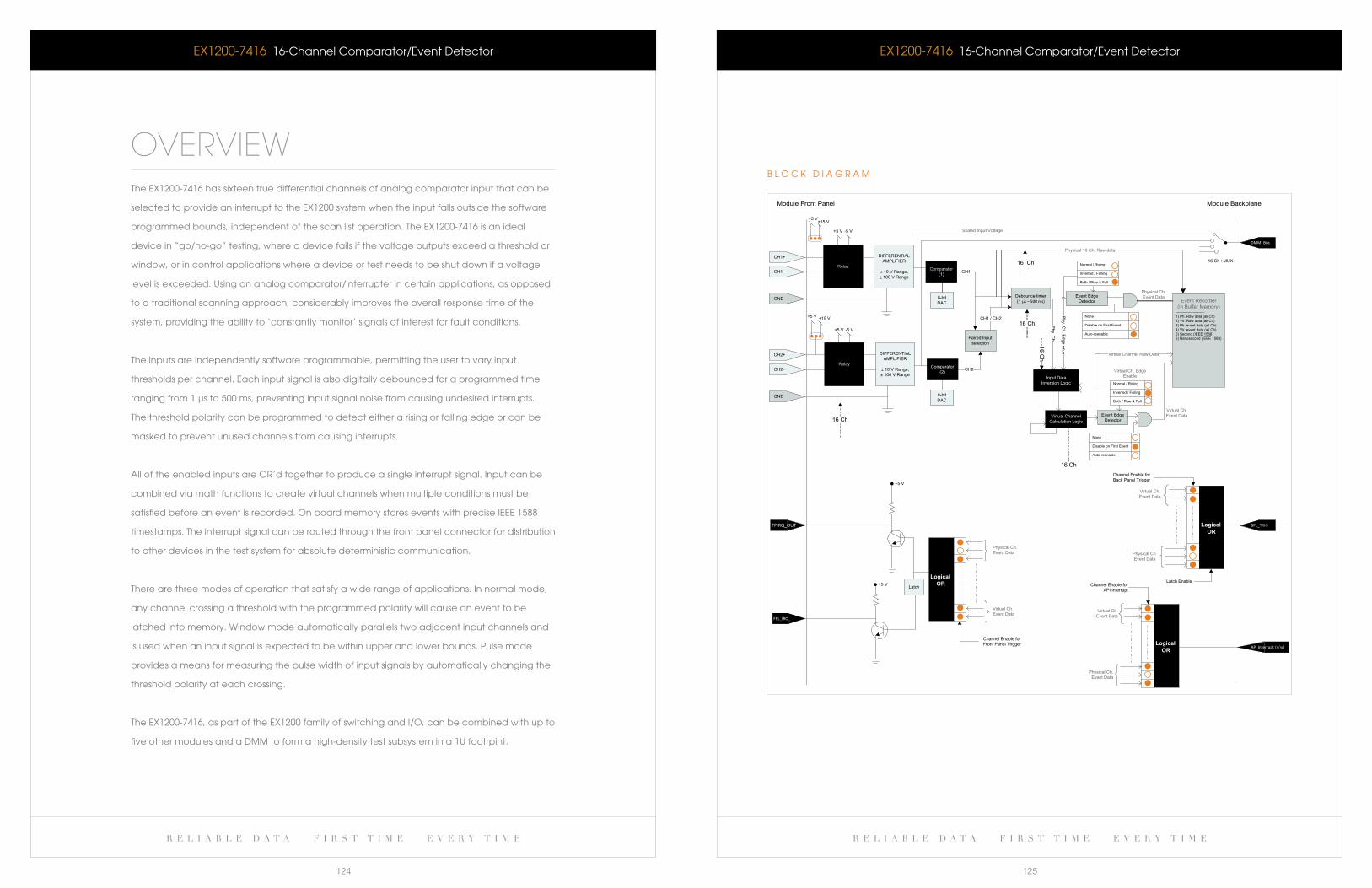
r e l i a b l e d a t a f i r s t t i m e e v e r y t i m e r e l i a b l e d a t a f i r s t t i m e e v e r y t i m e
124 125
+5 V
CH1-
CH1+ DIFFERENTIAL AMPLIFIER
± 10 V Range,± 100 V Range
8-bit DAC
Comparator (1)
Debounce timer (1 µs – 500 ms)
CH1
Input DataInversion Logic
Event Edge Detector Event Recorder
(in Buffer Memory)------------------------1) Ph. Raw data (all Ch)2) Vir. Raw data (all Ch)3) Ph. event data (all Ch)4) Vir. event data (all Ch)5) Second (IEEE 1588)6) Nanosecond (IEEE 1588)
Virtual Channel Calculation Logic
Event Edge Detector
Physical Ch. Event Data
Virtual Ch. Event Data
Physical Ch. Event Data
Virtual Ch. Event Data
Channel Enable for Front Panel Trigger
Latch
FPIRQ_OUT
+5 V
FPL_IRQ_OUT
Physical Ch. Event Data
Virtual Ch. Event Data
Channel Enable for Back Panel Trigger
Logical - OR
Latch Enable
16 Ch
BPL_TRIG
Physical Ch. Event Data
Virtual Ch. Event Data
Channel Enable for API Interrupt
-API Interrupt (s/w)
Module Front Panel Module Backplane
16 Ch : MUX
DMM_Bus
Scaled Input Voltage
Phy. Ch. Edge en.e
+5 V
Normal / Rising
Inverted / Falling
Both / Rise & Fall
Normal / Rising
Inverted / Falling
Both / Rise & Fall
GND
Relay
+15 V
+5 V -5 V
CH2-
CH2+ DIFFERENTIAL AMPLIFIER
± 10 V Range,± 100 V Range
Comparator (2)
+5 V
GND
Relay
+15 V
+5 V -5 V
8-bit DAC
Paired Input selection
CH2
CH1 / CH2
16 Ch
16 ChNone
Disable on First Event
Auto-reenable
None
Disable on First Event
Auto-reenable
Physical 16 Ch. Raw data
16 Ch
Phy. C
h.
Virtual Channel Raw Data
Virtual Ch. Edge Enable
16 Ch
Logical OR
-Logical OR
b l O c k D I a G R a M
eX1200-7416 16-channel comparator/event DetectoreX1200-7416 16-channel comparator/event Detector
OVERVIEWThe eX1200-7416 has sixteen true differential channels of analog comparator input that can be
selected to provide an interrupt to the eX1200 system when the input falls outside the software
programmed bounds, independent of the scan list operation. The eX1200-7416 is an ideal
device in “go/no-go” testing, where a device fails if the voltage outputs exceed a threshold or
window, or in control applications where a device or test needs to be shut down if a voltage
level is exceeded. Using an analog comparator/interrupter in certain applications, as opposed
to a traditional scanning approach, considerably improves the overall response time of the
system, providing the ability to ‘constantly monitor’ signals of interest for fault conditions.
The inputs are independently software programmable, permitting the user to vary input
thresholds per channel. each input signal is also digitally debounced for a programmed time
ranging from 1 μs to 500 ms, preventing input signal noise from causing undesired interrupts.
The threshold polarity can be programmed to detect either a rising or falling edge or can be
masked to prevent unused channels from causing interrupts.
all of the enabled inputs are OR’d together to produce a single interrupt signal. Input can be
combined via math functions to create virtual channels when multiple conditions must be
satisfiedbeforeaneventisrecorded.OnboardmemorystoreseventswithpreciseIEEE1588
timestamps. The interrupt signal can be routed through the front panel connector for distribution
to other devices in the test system for absolute deterministic communication.
There are three modes of operation that satisfy a wide range of applications. In normal mode,
any channel crossing a threshold with the programmed polarity will cause an event to be
latched into memory. window mode automatically parallels two adjacent input channels and
is used when an input signal is expected to be within upper and lower bounds. Pulse mode
provides a means for measuring the pulse width of input signals by automatically changing the
threshold polarity at each crossing.
The eX1200-7416, as part of the eX1200 family of switching and I/O, can be combined with up to
five other modules and a DMM to form a high-density test subsystem in a 1U footrpint.
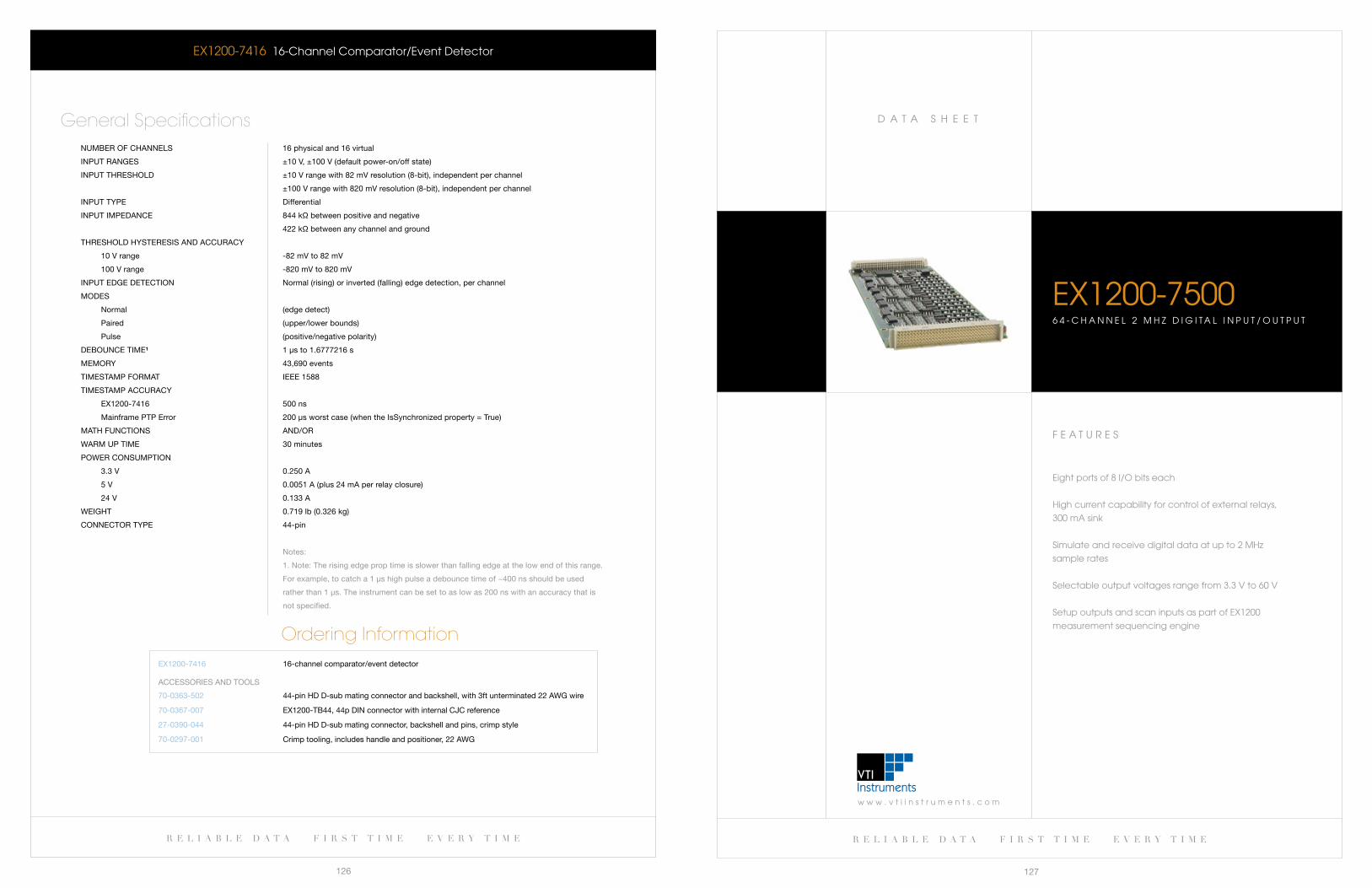
w w w . v t i i n s t r u m e n t s . c o m
D a T a S H e e T
r e l i a b l e d a t a f i r s t t i m e e v e r y t i m e
127
r e l i a b l e d a t a f i r s t t i m e e v e r y t i m e
126
F e a T U R e S
Eightportsof8I/Obitseach
High current capability for control of external relays,
300 ma sink
Simulate and receive digital data at up to 2 MHz
sample rates
Selectable output voltages range from 3.3 V to 60 V
Setup outputs and scan inputs as part of eX1200
measurement sequencing engine
eX1200-75006 4 - c H a N N e l 2 M H z D I G I T a l I N P U T / O U T P U T
eX1200-7416 16-channel comparator/event Detector
nUMber Of CHannels 16 physical and 16 virtual
inPUT ranges ±10 V, ±100 V (default power-on/off state)
inPUT THresHOlD ±10 V range with 82 mV resolution (8-bit), independent per channel
±100 V range with 820 mV resolution (8-bit), independent per channel
inPUT TyPe Differential
inPUT iMPeDanCe 844 kΩ between positive and negative
422 kΩ between any channel and ground
THresHOlD HysTeresis anD aCCUraCy
10 V range -82 mV to 82 mV
100 V range -820 mV to 820 mV
inPUT eDge DeTeCTiOn normal (rising) or inverted (falling) edge detection, per channel
MODes
normal (edge detect)
Paired (upper/lower bounds)
Pulse (positive/negative polarity)
DebOUnCe TiMe¹ 1 μs to 1.6777216 s
MeMOry 43,690 events
TiMesTaMP fOrMaT ieee 1588
TiMesTaMP aCCUraCy
eX1200-7416 500 ns
Mainframe PTP error 200 μs worst case (when the issynchronized property = True)
MaTH fUnCTiOns anD/Or
WarM UP TiMe 30 minutes
POWer COnsUMPTiOn
3.3 V 0.250 a
5 V 0.0051 a (plus 24 ma per relay closure)
24 V 0.133 a
WeigHT 0.719 lb (0.326 kg)
COnneCTOr TyPe 44-pin
notes:
1. note: The rising edge prop time is slower than falling edge at the low end of this range.
for example, to catch a 1 μs high pulse a debounce time of ~400 ns should be used
rather than 1 μs. The instrument can be set to as low as 200 ns with an accuracy that is
not specified.
General Specifications
Ordering InformationeX1200-7416 16-channel comparator/event detector
70-0363-502
70-0367-007
27-0390-044
70-0297-001
44-pin HD D-sub mating connector and backshell, with 3ft unterminated 22 aWg wire
eX1200-Tb44, 44p Din connector with internal CJC reference
44-pin HD D-sub mating connector, backshell and pins, crimp style
Crimp tooling, includes handle and positioner, 22 aWg
aCCessOries anD TOOls
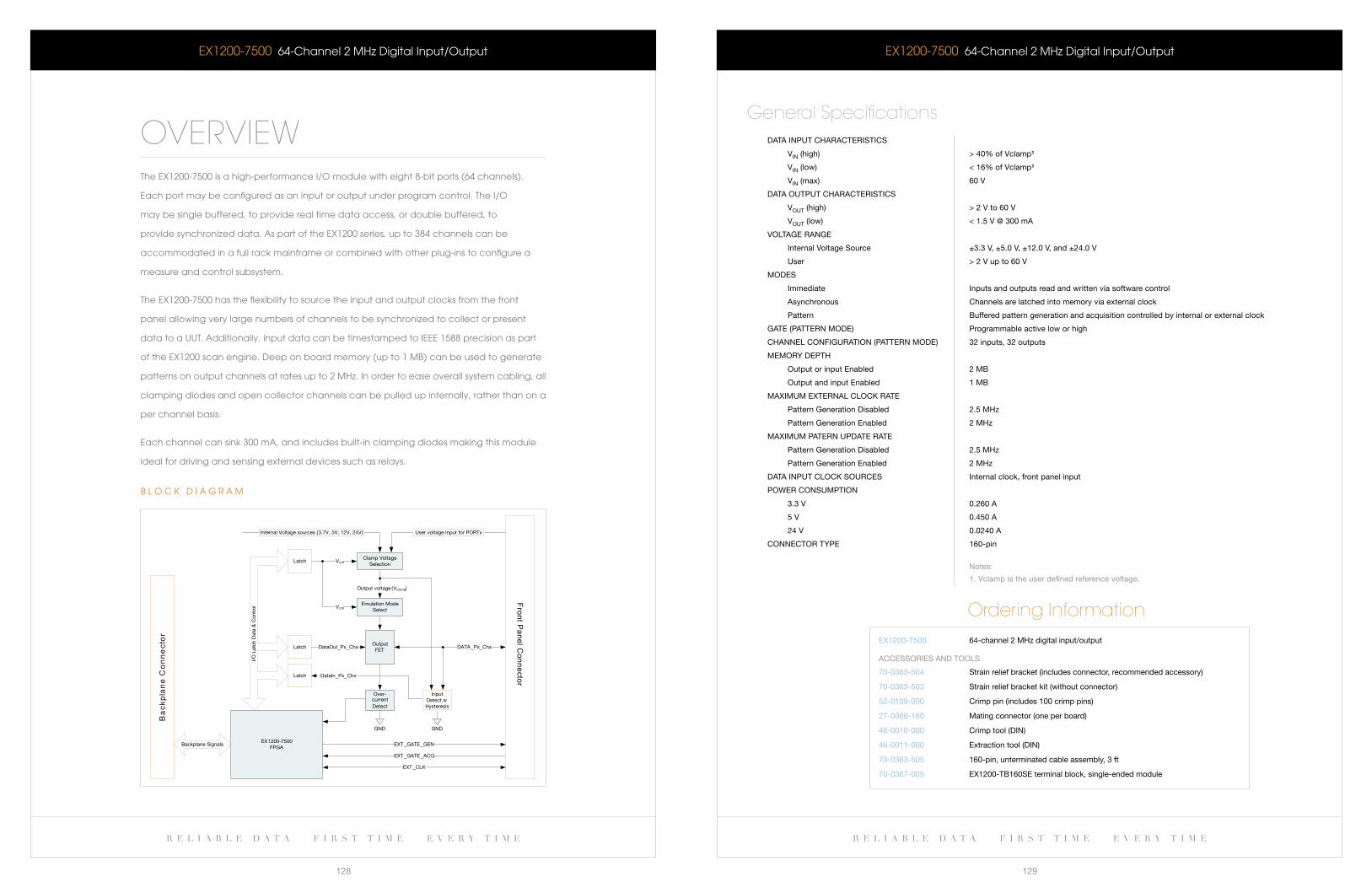
r e l i a b l e d a t a f i r s t t i m e e v e r y t i m e r e l i a b l e d a t a f i r s t t i m e e v e r y t i m e
128 129
eX1200-7500 64-channel 2 MHz Digital Input/Output
DaTa inPUT CHaraCTerisTiCs
Vin (high) > 40% of Vclamp¹
Vin (low) < 16% of Vclamp¹
Vin (max) 60 V
DaTa OUTPUT CHaraCTerisTiCs
VOUT (high) > 2 V to 60 V
VOUT (low) < 1.5 V @ 300 ma
VOlTage range
internal Voltage source ±3.3 V, ±5.0 V, ±12.0 V, and ±24.0 V
User > 2 V up to 60 V
MODes
immediate inputs and outputs read and written via software control
asynchronous Channels are latched into memory via external clock
Pattern buffered pattern generation and acquisition controlled by internal or external clock
gaTe (PaTTern MODe) Programmable active low or high
CHannel COnfigUraTiOn (PaTTern MODe) 32 inputs, 32 outputs
MeMOry DePTH
Output or input enabled 2 Mb
Output and input enabled 1 Mb
MaXiMUM eXTernal ClOCk raTe
Pattern generation Disabled 2.5 MHz
Pattern generation enabled 2 MHz
MaXiMUM PaTern UPDaTe raTe
Pattern generation Disabled 2.5 MHz
Pattern generation enabled 2 MHz
DaTa inPUT ClOCk sOUrCes internal clock, front panel input
POWer COnsUMPTiOn
3.3 V 0.260 a
5 V 0.450 a
24 V 0.0240 a
COnneCTOr TyPe 160-pin
notes:
1. Vclamp is the user defined reference voltage.
General Specifications
Ordering InformationeX1200-7500 64-channel 2 MHz digital input/output
70-0363-504
70-0363-503
52-0109-000
27-0088-160
46-0010-000
46-0011-000
70-0363-505
70-0367-005
strain relief bracket (includes connector, recommended accessory)
strain relief bracket kit (without connector)
Crimp pin (includes 100 crimp pins)
Mating connector (one per board)
Crimp tool (Din)
extraction tool (Din)
160-pin, unterminated cable assembly, 3 ft
eX1200-Tb160se terminal block, single-ended module
aCCessOries anD TOOls
eX1200-7500 64-channel 2 MHz Digital Input/Output
OVERVIEWTheEX1200-7500isahigh-performanceI/Omodulewitheight8-bitports(64channels).
each port may be configured as an input or output under program control. The I/O
may be single buffered, to provide real time data access, or double buffered, to
providesynchronizeddata.AspartoftheEX1200series,upto384channelscanbe
accommodated in a full rack mainframe or combined with other plug-ins to configure a
measure and control subsystem.
The eX1200-7500 has the flexibility to source the input and output clocks from the front
panel allowing very large numbers of channels to be synchronized to collect or present
datatoaUUT.Additionally,inputdatacanbetimestampedtoIEEE1588precisionaspart
of the eX1200 scan engine. Deep on board memory (up to 1 Mb) can be used to generate
patterns on output channels at rates up to 2 MHz. In order to ease overall system cabling, all
clamping diodes and open collector channels can be pulled up internally, rather than on a
per channel basis.
each channel can sink 300 ma, and includes built-in clamping diodes making this module
ideal for driving and sensing external devices such as relays.
_ _ _ _
V
/
Front Panel C
onnector
_ _
_ _
_
_ _
Ba
ck
pla
ne
Co
nn
ec
tor
OutputFET
DataOut Px Chx
Over-current Detect
Clamp Voltage Selection
Internal Voltage sources (3.7V, 5V, 12V, 24V)
DATA Px Chx
GND
Emulation Mode Select
Output voltage ( clamp)
InputDetect wHysteresis
GND
User voltage Input for PORTx
EX1200-7500FPGA
EXT GATE GEN
EXT GATE ACQ
EXT CLK
Latch
Latch
Latch
DataIn Px Chx
Vctrl
Vctrl
I/O L
atch
Dat
a &
Con
trol
Backplane Signals
b l O c k D I a G R a M
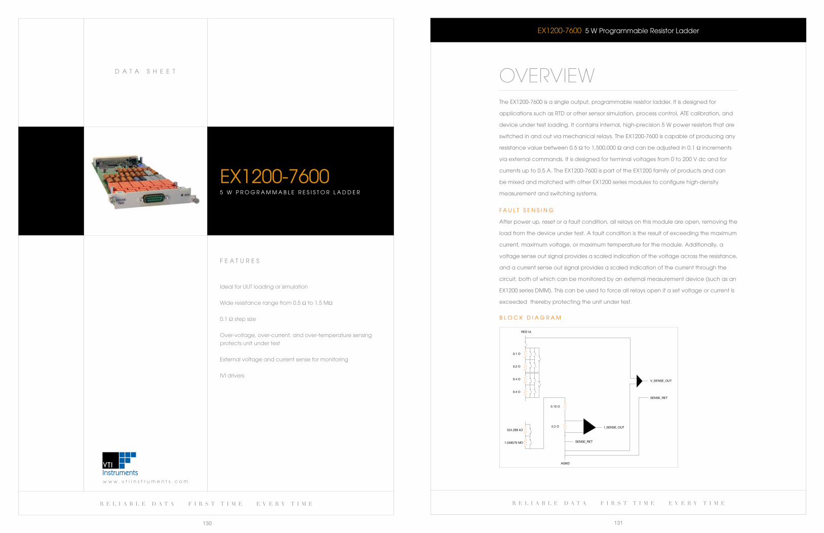
r e l i a b l e d a t a f i r s t t i m e e v e r y t i m e
131
w w w . v t i i n s t r u m e n t s . c o m
D a T a S H e e T
r e l i a b l e d a t a f i r s t t i m e e v e r y t i m e
130
eX1200-7600 5 w Programmable Resistor ladder
OVERVIEWThe eX1200-7600 is a single output, programmable resistor ladder. It is designed for
applications such as RTD or other sensor simulation, process control, aTe calibration, and
device under test loading. It contains internal, high-precision 5 w power resistors that are
switched in and out via mechanical relays. The eX1200-7600 is capable of producing any
resistance value between 0.5 Ω to 1,500,000 Ω and can be adjusted in 0.1 Ω increments
via external commands. It is designed for terminal voltages from 0 to 200 V dc and for
currents up to 0.5 a. The eX1200-7600 is part of the eX1200 family of products and can
be mixed and matched with other eX1200 series modules to configure high-density
measurement and switching systems.
F a U l T S e N S I N G
after power up, reset or a fault condition, all relays on this module are open, removing the
load from the device under test. a fault condition is the result of exceeding the maximum
current, maximum voltage, or maximum temperature for the module. additionally, a
voltage sense out signal provides a scaled indication of the voltage across the resistance,
and a current sense out signal provides a scaled indication of the current through the
circuit, both of which can be monitored by an external measurement device (such as an
eX1200 series DMM). This can be used to force all relays open if a set voltage or current is
exceeded thereby protecting the unit under test.
RES1A
0.1 O
0.2 O
0.4 O
0.4 O
1.048576 MO
524.288 kO0.2 O
AGND
V_SENSE_OUT
I_SENSE_OUT
SENSE_RET
SENSE_RET
0.15 O
b l O c k D I a G R a M
F e a T U R e S
Ideal for UUT loading or simulation
wide resistance range from 0.5 Ω to 1.5 MΩ
0.1 Ω step size
Over-voltage, over-current, and over-temperature sensing
protects unit under test
external voltage and current sense for monitoring
IVI drivers
eX1200-76005 w P R O G R a M M a b l e R e S I S T O R l a D D e R
w w w . v t i i n s t r u m e n t s . c o m
D a T a S H e e T
r e l i a b l e d a t a f i r s t t i m e e v e r y t i m e
133
r e l i a b l e d a t a f i r s t t i m e e v e r y t i m e
132
eX1200-IcaS w I T c H S O l U T I O N S
eX1200-7600 5 w Programmable Resistor ladder
MODel TyPe Programmable resistor load
CHannels 1
sWiTCHing TiMe < 5 ms
raTeD sWiTCH OPeraTiOns
Mechanical 5 x 10⁶
electrical 1 x 10⁵ (full load)
OVer TeMPeraTUre PrOTeCTiOn
PCb surface Temperature 102 °C (215.6 °f)
MaXiMUM sWiTCHing VOlTage 200 V aC rms
MaXiMUM sWiTCHing CUrrenT 0.5 a
MaXiMUM sWiTCHing/Carry POWer 5 W
POWer COnsUMPTiOn
3.3 V 0.129 a
5 V 0.0041 a (add 24 ma for each relay closure)
24 V 0.2 a (maximum value)
VOlTage OUTPUT range/gain 40:1 ±1% full-scale
CUrrenT OUTPUT range/gain 100:1 ±1% full-scale
seTTing aCCUraCy
0.5 – 60.0 Ω ±0.15 Ω
60.1 – 1,499,999 Ω ±0.25 % of programmed value
1,499,999.1 Ω – 2,097,152.6 Ω not specified
MiniMUM inCreMenT (resOlUTiOn) 0.1 Ω
COnneCTOr TyPe 15-pin
General Specifications
Ordering InformationeX1200-7600 5 W programmable resistor ladder
27-0076-015
27-0086-015
Mating connector
Connector backshell
aCCessOries anD TOOls
F e a T U R e S
High-density signal switching and routing
Integrated receiver connector provides superior
maintainability
eliminates cabling between switch modules and receiver
Internal analog bus for matrix expansion
lXI wired-Trigger bus synchronization
ethernet communications interface
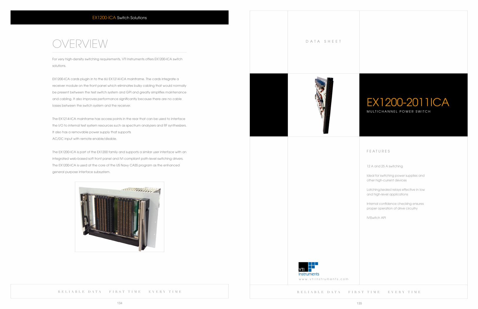
w w w . v t i i n s t r u m e n t s . c o m
D a T a S H e e T
r e l i a b l e d a t a f i r s t t i m e e v e r y t i m e
135
r e l i a b l e d a t a f i r s t t i m e e v e r y t i m e
134
F e a T U R e S
12 a and 25 a switching
Ideal for switching power supplies and
other high-current devices
latching/sealed relays effective in low
and high-level applications
Internal confidence checking ensures
proper operation of drive circuitry
IVISwitch aPI
eX1200-2011IcaM U l T I c H a N N e l P O w e R S w I T c H
eX1200-Ica Switch Solutions
OVERVIEWFor very high-density switching requirements, VTI Instruments offers eX1200-Ica switch
solutions.
eX1200-Ica cards plugin in to the 6U eX1214-Ica mainframe. The cards integrate a
receiver module on the front panel which eliminates bulky cabling that would normally
be present between the test switch system and GPI and greatly simplifies maintenance
and cabling. It also improves performance significantly because there are no cable
losses between the switch system and the receiver.
The eX1214-Ica mainframe has access points in the rear that can be used to interface
the I/O to internal test system resources such as spectrum analyzers and RF synthesizers.
It also has a removable power supply that supports
ac/Dc input with remote enable/disable.
The eX1200-Ica is part of the eX1200 family and supports a similar user interface with an
integrated web-based soft front panel and IVI compliant path-level switching drivers.
The eX1200-Ica is used at the core of the US Navy caSS program as the enhanced
general purpose interface subsystem.
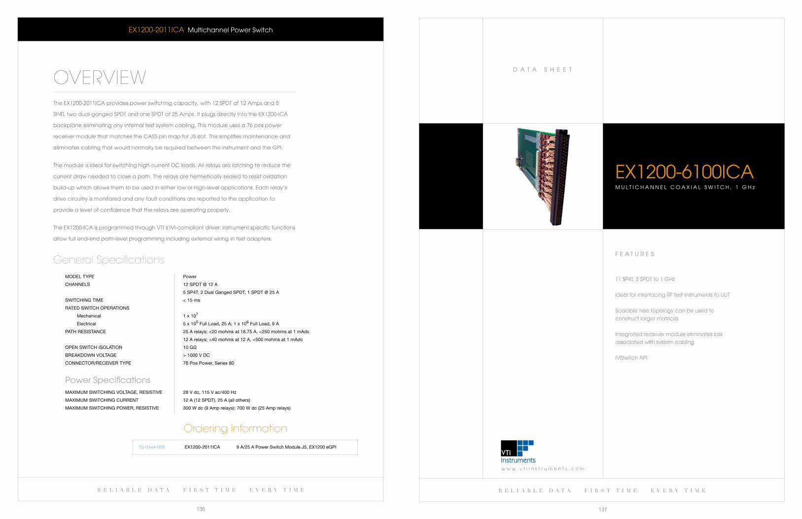
w w w . v t i i n s t r u m e n t s . c o m
D a T a S H e e T
r e l i a b l e d a t a f i r s t t i m e e v e r y t i m e
137
r e l i a b l e d a t a f i r s t t i m e e v e r y t i m e
136
F e a T U R e S
11 SP4T, 3 SPDT to 1 GHz
Ideal for interfacing RF test instruments to UUT
Scalable tree topology can be used to
construct larger matrices
Integrated receiver module eliminates loss
associated with system cabling
IVISwitch aPI
eX1200-6100IcaM U l T I c H a N N e l c O a X I a l S w I T c H , 1 G H z
eX1200-2011Ica Multichannel Power Switch
OVERVIEWThe eX1200-2011Ica provides power switching capacity, with 12 SPDT at 12 amps and 5
SP4T, two dual-ganged SPDT and one SPDT at 25 amps. It plugs directly into the eX1200-Ica
backplane eliminating any internal test system cabling. This module uses a 76 pos power
receiver module that matches the caSS pin map for J5 slot. This simplifies maintenance and
eliminates cabling that would normally be required between the instrument and the GPI.
The module is ideal for switching high-current Dc loads. all relays are latching to reduce the
current draw needed to close a path. The relays are hermetically sealed to resist oxidation
build-up which allows them to be used in either low or high-level applications. each relay’s
drive circuitry is monitored and any fault conditions are reported to the application to
provide a level of confidence that the relays are operating properly.
The eX1200-Ica is programmed through VTI’s IVI-compliant driver. Instrument specific functions
allow full end-end path-level programming including external wiring in test adapters.
MODel TyPe Power
CHannels 12 sPDT @ 12 a
5 sP4T, 2 Dual ganged sPDT, 1 sPDT @ 25 a
sWiTCHing TiMe < 15 ms
raTeD sWiTCH OPeraTiOns
Mechanical 1 x 10⁷
electrical 5 x 10⁵ full load, 25 a; 1 x 10⁶ full load, 9 a
PaTH resisTanCe 25 a relays; <20 mohms at 18.75 a, <250 mohms at 1 madc
12 a relays; <40 mohms at 12 a, <500 mohms at 1 madc
OPen sWiTCH isOlaTiOn 10 gΩ
breakDOWn VOlTage > 1000 V DC
COnneCTOr/reCeiVer TyPe 76 Pos Power, series 80
Power SpecificationsMaXiMUM sWiTCHing VOlTage, resisTiVe 28 V dc, 115 V ac/400 Hz
MaXiMUM sWiTCHing CUrrenT 12 a (12 sPDT), 25 a (all others)
MaXiMUM sWiTCHing POWer, resisTiVe 300 W dc (9 amp relays); 700 W dc (25 amp relays)
General Specifications
Ordering Information
70-0444-000 9 a/25 a Power switch Module J5, eX1200 egPieX1200-2011iCa
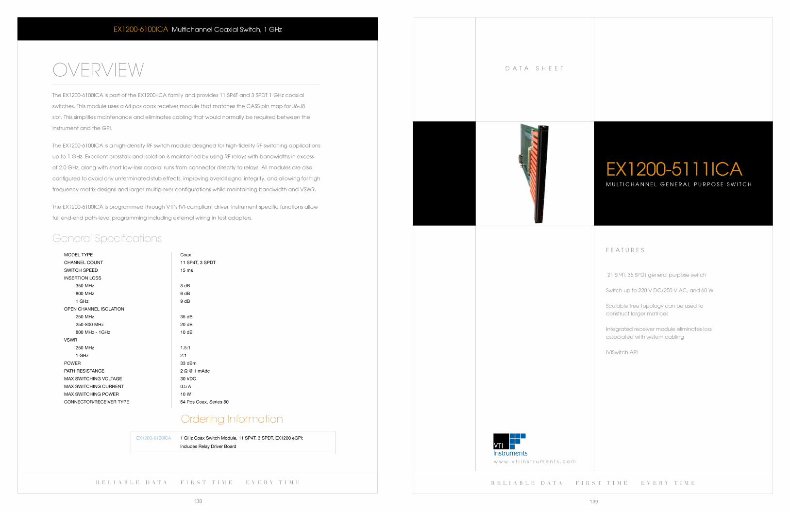
w w w . v t i i n s t r u m e n t s . c o m
D a T a S H e e T
r e l i a b l e d a t a f i r s t t i m e e v e r y t i m e
139
r e l i a b l e d a t a f i r s t t i m e e v e r y t i m e
138
F e a T U R e S
21 SP4T, 35 SPDT general purpose switch
Switch up to 220 V Dc/250 V ac, and 60 w
Scalable tree topology can be used to
construct larger matrices
Integrated receiver module eliminates loss
associated with system cabling
IVISwitch aPI
eX1200-5111IcaM U l T I c H a N N e l G e N e R a l P U R P O S e S w I T c H
eX1200-6100Ica Multichannel coaxial Switch, 1 GHz
OVERVIEWThe eX1200-6100Ica is part of the eX1200-Ica family and provides 11 SP4T and 3 SPDT 1 GHz coaxial
switches.Thismoduleusesa64poscoaxreceivermodulethatmatchestheCASSpinmapforJ6-J8
slot. This simplifies maintenance and eliminates cabling that would normally be required between the
instrument and the GPI.
The eX1200-6100Ica is a high-density RF switch module designed for high-fidelity RF switching applications
up to 1 GHz. excellent crosstalk and isolation is maintained by using RF relays with bandwidths in excess
of 2.0 GHz, along with short low-loss coaxial runs from connector directly to relays. all modules are also
configured to avoid any unterminated stub effects, improving overall signal integrity, and allowing for high
frequency matrix designs and larger multiplexer configurations while maintaining bandwidth and VSwR.
The eX1200-6100Ica is programmed through VTI’s IVI-compliant driver. Instrument specific functions allow
full end-end path-level programming including external wiring in test adapters.
MODel TyPe Coax
CHannel COUnT 11 sP4T, 3 sPDT
sWiTCH sPeeD 15 ms
inserTiOn lOss
350 MHz 3 db
800 MHz 6 db
1 gHz 9 db
OPen CHannel isOlaTiOn
250 MHz 35 db
250-800 MHz 20 db
800 MHz - 1gHz 10 db
VsWr
250 MHz 1.5:1
1 gHz 2:1
POWer 33 dbm
PaTH resisTanCe 2 Ω @ 1 madc
MaX sWiTCHing VOlTage 30 VDC
MaX sWiTCHing CUrrenT 0.5 a
MaX sWiTCHing POWer 10 W
COnneCTOr/reCeiVer TyPe 64 Pos Coax, series 80
General Specifications
Ordering Information
eX1200-6100iCa 1 gHz Coax switch Module, 11 sP4T, 3 sPDT, eX1200 egPi;
includes relay Driver board
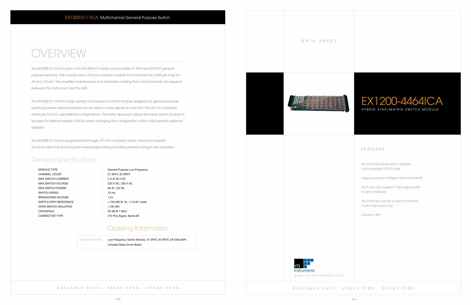
w w w . v t i i n s t r u m e n t s . c o m
D a T a S H e e T
r e l i a b l e d a t a f i r s t t i m e e v e r y t i m e
141
r e l i a b l e d a t a f i r s t t i m e e v e r y t i m e
140
F e a T U R e S
64 channel 4-pole switch creates
multi-purpose GPI I/O pins
legacy support of digital test instruments
each pin can support 1 GHz signal path
to rear interface
all channels can be routed to internal
matrix expansion bus
IVISwitch aPI
eX1200-4464IcaH Y b R I D S T a R / M a T R I X S w I T c H M O D U l e
eX1200-5111Ica Multichannel General Purpose Switch
OVERVIEWThe eX1200-5111Ica is part of the eX1200-Ica family and provides 21 SP4T and 35 SPDT general
purpose switches. This module uses a 210 pos receiver module that matches the caSS pin map for
J9 and J10 slot. This simplifies maintenance and eliminates cabling that would normally be required
between the instrument and the GPI.
The eX1200-5111Ica is a high-density low-frequency switch module designed for general purpose
switching where individual relays can be used to route signals to and from the UUT or combined
externally to form user-defined configurations. The latter approach allows the same switch module to
be used for testing multiple UUTs by simply changing the configuration within a UUT-specific external
adapter.
The eX1200-5111Ica is programmed through VTI’s IVI-compliant driver. Instrument specific
functions allow full end-end path-level programming including external wiring in test adapters.
MODUle TyPe general Purpose low frequency
CHannel COUnT 21 sP4T, 35 sPDT
MaX sWiTCH CUrrenT 2 a @ 30 V DC
MaX sWiTCH VOlTage 220 V DC, 250 V aC
MaX sWiTCH POWer 60 W, 125 Va
sWiTCH sPeeD 15 ms
breakDOWn VOlTage 1 kV
sWiTCH PaTH resisTanCe < 700 MΩ @ 1a, <1 Ω @1 madc
OPen sWiTCH isOlaTiOn >10k MΩ
CrOssTalk 40 db @ 1 MHz
COnneCTOr TyPe 210 Pos signal, series 80
General Specifications
Ordering Information
eX1200-5111iCa low frequency switch Module, 21 sP4T, 35 sPDT, eX1200 egPi;
includes relay Driver board
r e l i a b l e d a t a f i r s t t i m e e v e r y t i m e r e l i a b l e d a t a f i r s t t i m e e v e r y t i m e
142 143
MODUle TyPe Hyrbid star/Matrix
CHannels 64
CHannel COnfigUraTiOn Modified 4-pole star
64 to 6 lf matrix
COnneCTOr/reCeiVer TyPe 64 P COaX, series 80
electrical Specifications GPI-Digital Path
sWiTCHing sPeeD < 5 ms
inserTiOn lOss ≤ 1.5 db @ 100 MHz
≤ 3.0 db @ 500 MHz
VOlTage sTanDing WaVe raTiO ≤ 1.5:1 at 100 MHz
≤ 2.0:1 at 500 MHz
MaXiMUM POWer +27 dbm (1/2 W into 50 Ω)
freqUenCy range DC to > 500 MHz
iMPeDanCe 50 Ω
PaTH resisTanCe < 1 Ω at 1 madc
COnneCTOr/insTrUMenT inTerfaCe TyPe 34 pin iDC x 4
electrical Specifications GPI-HF Path
sWiTCHing sPeeD ≤ 5 ms
inserTiOn lOss ≤ 1.5 db @ 100 MHz
≤ 1.7 db @ 500 MHz
≤ 3 db @ 1 gHz
VOlTage sTanDing WaVe raTiO <1.3:1 at 100 MHz
<1.5:1 at 500 MHz
<2.0:1 at 1 gHz
MaXiMUM POWer +27 dbm (1/2 W into 50 Ω)
freqUenCy range DC to > 1 gHz
iMPeDanCe 50 Ω
PaTH resisTanCe < 1 Ω at 1 madc
COnneCTOr/insTrUMenT inTerfaCe TyPe COnn, 65P MiCrO-COaX blinD MaTe
electrical Specifications GPI-lF Path
sWiTCHing sPeeD ≤ 5 ms
inserTiOn lOss ≤ 1.0 db @ 50 MHz
≤ 3.0 db @ 100 MHz
VOlTage sTanDing WaVe raTiO ≤ 1.5:1 at 50 MHz
≤ 2.5:1 at 100 MHz
MaXiMUM POWer +27 dbm (1/2 W into 50 Ω)
freqUenCy range DC to > 500 MHz
iMPeDanCe 50 Ω
PaTH resisTanCe < 1 Ω at 1 madc
note: *electrical specifications are subject to change
eX1200-4464Ica Hybrid Star/Matrix Switch Module
General Specifications
Ordering Information
eX1200-4464iCa Hybrid star/Matrix switch Module J11-J17, eX1200 egPi
eX1200-4464Ica Hybrid Star/Matrix Switch Module
OVERVIEWThe eX1200-4464Ica is part of the eX1200-Ica family
and incorporates high-fidelity four-pole switching to
create multi-purpose I/O pins at the receiver interface.
The eX1200-4464Ica integrates an active relay card
withaseries-80compatiblecoaxmodule.Afour-pole
switch is connected to each of the 64 pins, and provides
switched paths to either digital test instruments, a 1 GHz
connector at the back of the eX1200-Ica mainframe,
or to a low-frequency analog matrix that can be used
to connect the GPI pin to other test system assets or to
other I/O on other VT4000-c modules.
The four-pole switch is designed to minimize any
stubbing effects normally associated with star/matrix
switch topologies. Dedicated ground planes are
embedded in the layout and further improve signal
integrity across all paths.
Hybrid Star Topology (1 of 64)
The path that connects a GPI pin to a digital test
channel is the default state upon power up. This ensures
that no modifications for legacy TPSs are required to
account for the presence of this module. The channel
pathsareprogrammaticallycontrolledinbanksof8.This
means that a single receiver block can mix and match
a combination of up to eight analog measurement,
digital test and high frequency signal types.
when a bank of channels is programmed to operate
in high-frequency mode, the GPI pins are routed
through a 1 GHz path to a blind-mate micro-coax
connector at the rear of the eX1200-Ica mainframe.
RF instrumentation such as spectrum analyzers and
synthesizers can then be routed to the GPI.
In low-frequency mode, a path is established to an
internal multiplexer that routes to the internal analog
expansion backplane. GPI signals can be routed to
instruments such as DMMs or counters, or to other
eX1200-4464Ica modules within the mainframe.
The eX1200-4464Ica is programmed through VTI’s
IVI-compliant driver. Instrument specific functions allow
full end-end path-level programming including external
wiring in test adapters.
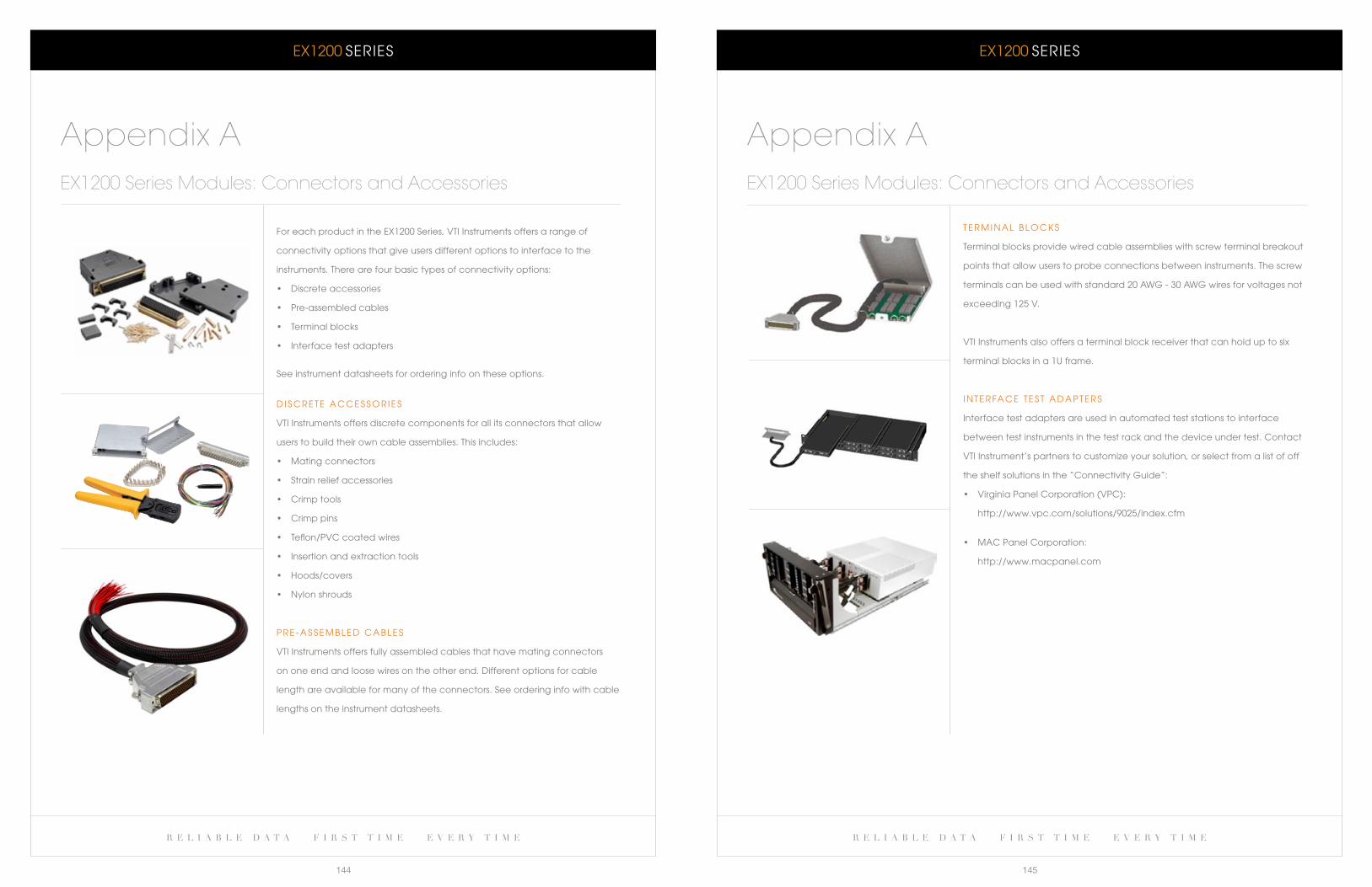
eX1200 SeRIeS eX1200 SeRIeS
r e l i a b l e d a t a f i r s t t i m e e v e r y t i m e r e l i a b l e d a t a f i r s t t i m e e v e r y t i m e
144 145
T e R M I N a l b l O c k S
Terminal blocks provide wired cable assemblies with screw terminal breakout
points that allow users to probe connections between instruments. The screw
terminals can be used with standard 20 awG - 30 awG wires for voltages not
exceeding 125 V.
VTI Instruments also offers a terminal block receiver that can hold up to six
terminal blocks in a 1U frame.
I N T e R Fa c e T e S T a D a P T e R S
Interface test adapters are used in automated test stations to interface
between test instruments in the test rack and the device under test. contact
VTI Instrument’s partners to customize your solution, or select from a list of off
the shelf solutions in the “connectivity Guide”:
• VirginiaPanelCorporation(VPC):
http://www.vpc.com/solutions/9025/index.cfm
• MACPanelCorporation:
http://www.macpanel.com
Appendix AEX1200 Series Modules: Connectors and Accessories
For each product in the eX1200 Series, VTI Instruments offers a range of
connectivity options that give users different options to interface to the
instruments. There are four basic types of connectivity options:
• Discreteaccessories
• Pre-assembledcables
• Terminalblocks
• Interfacetestadapters
See instrument datasheets for ordering info on these options.
D I S c R e T e a c c e S S O R I e S
VTI Instruments offers discrete components for all its connectors that allow
users to build their own cable assemblies. This includes:
• Matingconnectors
• Strainreliefaccessories
• Crimptools
• Crimppins
• Teflon/PVCcoatedwires
• Insertionandextractiontools
• Hoods/covers
• Nylonshrouds
P R e - a S S e M b l e D c a b l e S
VTI Instruments offers fully assembled cables that have mating connectors
on one end and loose wires on the other end. Different options for cable
length are available for many of the connectors. See ordering info with cable
lengths on the instrument datasheets.
Appendix AEX1200 Series Modules: Connectors and Accessories
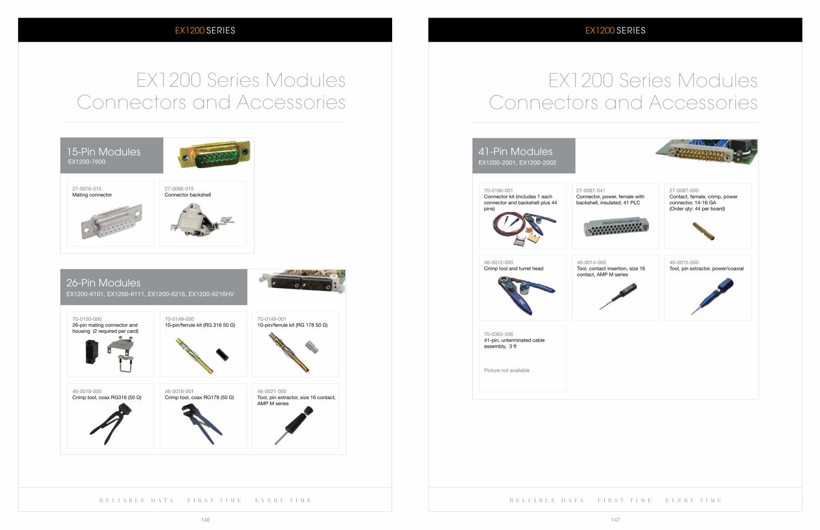
eX1200 SeRIeS eX1200 SeRIeS
r e l i a b l e d a t a f i r s t t i m e e v e r y t i m e r e l i a b l e d a t a f i r s t t i m e e v e r y t i m e
146 147
41-Pin ModuleseX1200-2001, eX1200-2002
27-0087-041Connector, power, female with backshell, insulated, 41 PlC
27-0087-000Contact, female, crimp, power connector, 14-16 ga (Order qty: 44 per board)
46-0012-000Crimp tool and turret head
46-0015-000Tool, pin extractor, power/coaxial
70-0363-50641-pin, unterminated cable assembly, 3 ft
Picture not available
EX1200 Series ModulesConnectors and Accessories
70-0190-001Connector kit (includes 1 each connector and backshell plus 44 pins)
46-0014-000Tool, contact insertion, size 16 contact, aMP M series
15-Pin Modules eX1200-7600
26-Pin ModuleseX1200-6101, eX1200-6111, eX1200-6216, eX1200-6216HV
EX1200 Series ModulesConnectors and Accessories
27-0076-015Mating connector
27-0086-015Connector backshell
70-0150-00026-pin mating connector and housing (2 required per card)
70-0149-00010-pin/ferrule kit (rg 316 50 Ω)
70-0149-00110-pin/ferrule kit (rg 178 50 Ω)
46-0018-000Crimp tool, coax rg316 (50 Ω)
46-0018-001Crimp tool, coax rg178 (50 Ω)
46-0021-000Tool, pin extractor, size 16 contact, aMP M series
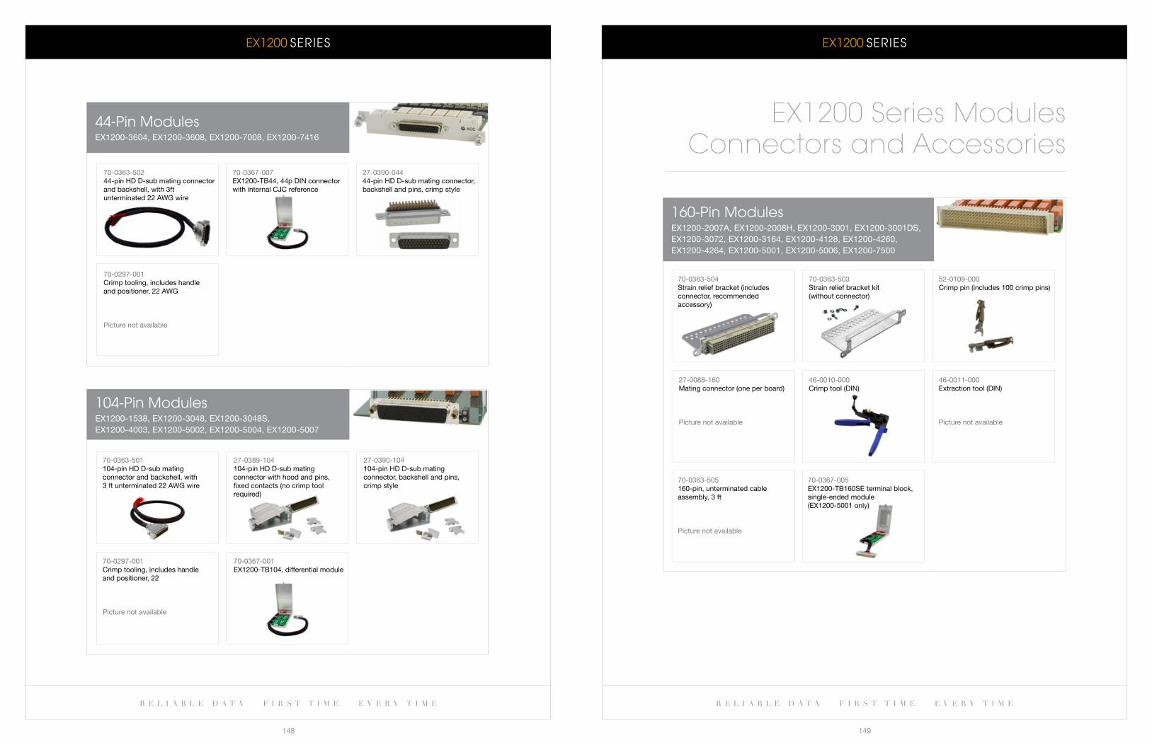
eX1200 SeRIeS eX1200 SeRIeS
r e l i a b l e d a t a f i r s t t i m e e v e r y t i m e r e l i a b l e d a t a f i r s t t i m e e v e r y t i m e
148 149
160-Pin ModuleseX1200-2007a, eX1200-2008H, eX1200-3001, eX1200-3001Ds, eX1200-3072, eX1200-3164, eX1200-4128, eX1200-4260, eX1200-4264, eX1200-5001, eX1200-5006, eX1200-7500
70-0363-504strain relief bracket (includes connector, recommended accessory)
70-0363-503strain relief bracket kit (without connector)
52-0109-000Crimp pin (includes 100 crimp pins)
27-0088-160Mating connector (one per board)
Picture not available
46-0010-000Crimp tool (Din)
70-0363-505160-pin, unterminated cable assembly, 3 ft
Picture not available
46-0011-000extraction tool (Din)
Picture not available
EX1200 Series ModulesConnectors and Accessories
70-0367-005eX1200-Tb160se terminal block, single-ended module(eX1200-5001 only)
104-Pin ModuleseX1200-1538, eX1200-3048, eX1200-3048s, eX1200-4003, eX1200-5002, eX1200-5004, eX1200-5007
44-Pin ModuleseX1200-3604, eX1200-3608, eX1200-7008, eX1200-7416
70-0363-50244-pin HD D-sub mating connector and backshell, with 3ft unterminated 22 aWg wire
70-0367-007eX1200-Tb44, 44p Din connector with internal CJC reference
27-0390-04444-pin HD D-sub mating connector, backshell and pins, crimp style
70-0297-001Crimp tooling, includes handle and positioner, 22 aWg
Picture not available
70-0363-501104-pin HD D-sub mating connector and backshell, with 3 ft unterminated 22 aWg wire
27-0389-104104-pin HD D-sub mating connector with hood and pins,fixed contacts (no crimp tool required)
27-0390-104104-pin HD D-sub mating connector, backshell and pins, crimp style
70-0297-001Crimp tooling, includes handle and positioner, 22
Picture not available
70-0367-001eX1200-Tb104, differential module
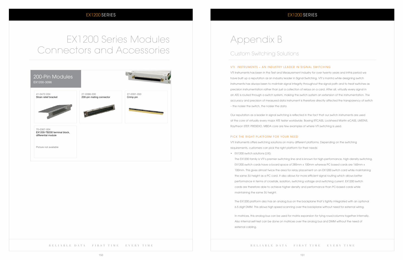
eX1200 SeRIeS eX1200 SeRIeS
r e l i a b l e d a t a f i r s t t i m e e v e r y t i m e r e l i a b l e d a t a f i r s t t i m e e v e r y t i m e
150 151
V T I I N S T R U M e N T S – a N I N D U S T RY l e a D e R I N S I G N a l S w I T c H I N G
VTI Instruments has been in the Test and Measurement industry for over twenty years and inthis period we
have built up a reputation as an industry leader in Signal Switching. VTI’s mantra while designing switch
instruments has always been to maintain signal integrity throughout the signal path and to treat switches as
precision instrumentation rather than just a collection of relays on a card. after all, virtually every signal in
an aTe is routed through a switch system, making the switch system an extension of the instrumentation. The
accuracy and precision of measured data instrument is therefore directly affected the transparency of switch
– the noisier the switch, the noisier the data.
Our reputation as a leader in signal switching is reflected in the fact that our switch instruments are used
at the core of virtually every major aTe tester worldwide. boeing RTcaSS, lockheed Martin ecaSS, lMSTaR,
Raytheon STeP, PReSIDIO, MbDa core are few examples of where VTI switching is used.
P I c k T H e R I G H T P l aT F O R M F O R Y O U R N e e D
VTI Instruments offers switching solutions on many different platforms. Depending on the switching
requirements, customers can pick the right platform for their needs:
• EX1200switchsolutions(LXI):
The eX1200 family is VTI’s premier switching line and is known for high-performance, high-density switching.
EX1200switchcardshaveaboardspaceof285mmx100mmwhereasPCbasedcardsare160mmx
100mm. This gives almost twice the area for relay placement on an eX1200 switch card while maintaining
the same 3U height as a Pc card. It also allows for more efficient signal routing which allows better
performance in terms of crosstalk, isolation, switching voltage and switching current. eX1200 switch
cards are therefore able to achieve higher density and performance than Pc-based cards while
maintaining the same 3U height.
The eX1200 platform also has an analog bus on the backplane that’s tightly integrated with an optional
6.5 digit DMM. This allows high speed scanning over the backplane without need for external wiring.
In matrices, this analog bus can be used for matrix expansion for tying rows/columns together internally.
also internal self-test can be done on matrices over the analog bus and DMM without the need of
external cabling.
Appendix BCustom Switching Solutions
200-Pin ModuleseX1200-3096
41-0472-034strain relief bracket
27-0388-200200-pin mating connector
27-0391-050Crimp pin
70-0367-004eX1200-Tb200 terminal block, differential module
Picture not available
EX1200 Series ModulesConnectors and Accessories
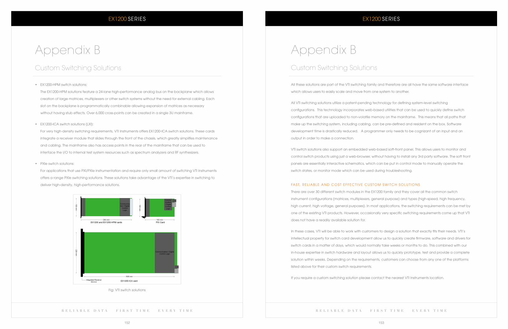
eX1200 SeRIeS eX1200 SeRIeS
r e l i a b l e d a t a f i r s t t i m e e v e r y t i m e r e l i a b l e d a t a f i r s t t i m e e v e r y t i m e
152 153
all these solutions are part of the VTI switching family and therefore are all have the same software interface
which allows users to easily scale and move from one system to another.
all VTI switching solutions utilize a patent-pending technology for defining system-level switching
configurations. This technology incorporates web-based utilities that can be used to quickly define switch
configurations that are uploaded to non-volatile memory on the mainframe. This means that all paths that
make up the switching system, including cabling, can be pre-defined and resident on the box. Software
development time is drastically reduced. a programmer only needs to be cognizant of an input and an
output in order to make a connection.
VTI switch solutions also support an embedded web-based soft-front panel. This allows users to monitor and
control switch products using just a web-browser, without having to install any 3rd party software. The soft front
panels are essentially interactive schematics, which can be put in control mode to manually operate the
switch states, or monitor mode which can be used during troubleshooting.
Fa S T, R e l I a b l e a N D c O S T e F F e c T I V e c U S T O M S w I T c H S O l U T I O N S
There are over 30 different switch modules in the eX1200 family and they cover all the common switch
instrument configurations (matrices, multiplexers, general purpose) and types (high-speed, high frequency,
high current, high voltage, general purposes). In most applications, the switching requirements can be met by
one of the existing VTI products. However, occasionally very specific switching requirements come up that VTI
does not have a readily available solution for.
In these cases, VTI will be able to work with customers to design a solution that exactly fits their needs. VTI’s
intellectual property for switch card development allow us to quickly create firmware, software and drivers for
switch cards in a matter of days, which would normally take weeks or months to do. This combined with our
in-house expertise in switch hardware and layout allows us to quickly prototype, test and provide a complete
solution within weeks. Depending on the requirements, customers can choose from any one of the platforms
listed above for their custom switch requirements.
If you require a custom switching solution please contact the nearest VTI Instruments location.
Appendix BCustom Switching Solutions
• EX1200-HPMswitchsolutions:
The eX1200-HPM solutions feature a 24-lane high-performance analog bus on the backplane which allows
creation of large matrices, multiplexers or other switch systems without the need for external cabling. each
slot on the backplane is programmatically combinable allowing expansion of matrices as necessary
without having stub effects. Over 6,000 cross-points can be created in a single 3U mainframe.
• EX1200-ICAswitchsolutions(LXI):
For very high-density switching requirements, VTI Instruments offers eX1200-Ica switch solutions. These cards
integrate a receiver module that slides through the front of the chassis, which greatly simplifies maintenance
and cabling. The mainframe also has access points in the rear of the mainframe that can be used to
interface the I/O to internal test system resources such as spectrum analyzers and RF synthesizers.
• PXIeswitchsolutions:
For applications that use PXI/PXIe instrumentation and require only small amount of switching VTI Instruments
offers a range PXIe switching solutions. These solutions take advantage of the VTI’s expertise in switching to
deliver high-density, high-performance solutions.
Appendix BCustom Switching Solutions
Fig: VTI switch solutions
r e l i a b l e d a t a f i r s t t i m e e v e r y t i m e
vti iNstrUmENtsH i g H - D e n s i t y s w i t c H i n g a n D D a t a a c q u i s i t i o n s y s t e m s
EX1200 series
VTI Instruments Corporation 2031 Main Street World Headquarters Irvine, CA 92614 USA Phone: +1 949 955 1894
VTI Instruments Pvt. Ltd. 135, II & III Floors Bangalore Instrument Division Infantry Road Bangalore – 560 001 India Phone: +91 80 4040 7900
VTI Instruments Corporation 5425 Warner Road, Suite 13 Cleveland Instrument Division Valley View, OH 44125 USA Phone: +1 216 447 8950
VTI Instruments Ltd. 4 The Paddock United Kingdom Lower Boddington Northants NN11 6YF UK Phone: +44 (0)1295 660008