Embed Size (px)
Citation preview

EX3400 Switch Hardware Guide
Published
2020-12-15

Juniper Networks, Inc.1133 Innovation WaySunnyvale, California 94089USA408-745-2000www.juniper.net
Juniper Networks, the Juniper Networks logo, Juniper, and Junos are registered trademarks of Juniper Networks, Inc. inthe United States and other countries. All other trademarks, service marks, registered marks, or registered service marksare the property of their respective owners.
Juniper Networks assumes no responsibility for any inaccuracies in this document. Juniper Networks reserves the rightto change, modify, transfer, or otherwise revise this publication without notice.
EX3400 Switch Hardware GuideCopyright © 2020 Juniper Networks, Inc. All rights reserved.
The information in this document is current as of the date on the title page.
YEAR 2000 NOTICE
Juniper Networks hardware and software products are Year 2000 compliant. Junos OS has no known time-relatedlimitations through the year 2038. However, the NTP application is known to have some difficulty in the year 2036.
END USER LICENSE AGREEMENT
The Juniper Networks product that is the subject of this technical documentation consists of (or is intended for use with)Juniper Networks software. Use of such software is subject to the terms and conditions of the EndUser License Agreement(“EULA”) posted at https://support.juniper.net/support/eula/. By downloading, installing or using such software, youagree to the terms and conditions of that EULA.
ii
Table of Contents
About the Documentation | xi
Documentation and Release Notes | xi
Using the Examples in This Manual | xi
Merging a Full Example | xii
Merging a Snippet | xiii
Documentation Conventions | xiii
Documentation Feedback | xvi
Requesting Technical Support | xvi
Self-Help Online Tools and Resources | xvii
Creating a Service Request with JTAC | xvii
Overview1EX3400 System Overview | 19
EX3400 Switches Hardware Overview | 19
Benefits of the EX3400 Switch | 19
EX3400 Switches First View | 20
Uplink Ports | 20
Virtual Chassis | 21
Console Ports | 21
Power over Ethernet Ports | 21
EX3400 Switch Models | 22
EX3400 Switch Hardware and CLI Terminology Mapping | 23
Chassis Physical Specifications for EX3400 Switches | 26
Field-Replaceable Units in EX3400 Switches | 27
EX3400 Chassis | 28
Front Panel of an EX3400 Switch | 28
Rear Panel of an EX3400 Switch | 30
Chassis Status LEDs in EX3400 Switches | 31
Management Port LEDs in EX3400 Switches | 33
iii
RJ-45 Network Port and Uplink Port LEDs in EX3400 Switches | 34
EX3400 Cooling System | 38
Airflow Direction in EX3400 Switch Models | 38
Front-to-Back Airflow | 39
Back-to-Front Airflow | 39
EX3400 Power System | 41
AC Power Supply in EX3400 Switches | 41
AC Power Supply LEDs in EX3400 Switches | 42
AC Power Cord Specifications for EX3400 Switches | 44
DC Power Supply in EX3400 Switches | 45
Characteristics of a DC Power Supply | 46
DC Power Supply Airflow | 47
DC Power Supply LEDs in EX3400 Switches | 47
Power Specifications for EX3400 Switches | 48
Site Planning, Preparation, and Specifications2Site Preparation Checklist for EX3400 Switches | 51
EX3400 Site Guidelines and Requirements | 54
Environmental Requirements and Specifications for EX Series Switches | 54
General Site Guidelines | 59
Site Electrical Wiring Guidelines | 60
Rack Requirements | 60
Cabinet Requirements | 62
Clearance Requirements for Airflow and Hardware Maintenance for EX3400 Switches | 63
EX3400 Network Cable and Transceiver Planning | 65
Pluggable Transceivers Supported on EX3400 Switches | 66
SFP+ Direct Attach Copper Cables for EX Series Switches | 67
Cable Specifications | 67
List of DAC Cables Supported on EX Series Switches | 68
iv

Standards Supported by These Cables | 68
QSFP+ Direct Attach Copper Cables for EX Series Switches | 69
Cable Specifications | 69
DAC Cables Supported on EX3400, EX4300, EX4550, EX4600, EX9251, and EX9253Switches | 70
Understanding EX Series Switches Fiber-Optic Cable Signal Loss, Attenuation, andDispersion | 70
Signal Loss in Multimode and Single-Mode Fiber-Optic Cable | 71
Attenuation and Dispersion in Fiber-Optic Cable | 71
Calculating the Fiber-Optic Cable Power Budget for EX Series Devices | 72
Calculating the Fiber-Optic Cable Power Margin for EX Series Devices | 72
EX3400 Management Cable Specifications and Pinouts | 74
Management Cable Specifications | 75
Console Port Connector Pinout Information | 75
RJ-45 Management Port Connector Pinout Information | 76
USB Port Specifications for an EX Series Switch | 77
RJ-45 Port, SFP Port, SFP+ Port, QSFP+ Port, and QSFP28 Port Connector PinoutInformation | 77
SFP+ Uplink Port Connector Pinout Information for an EX3400 Switch | 82
QSFP+ Uplink Port Connector Pinout Information for an EX3400 Switch | 83
RJ-45 to DB-9 Serial Port Adapter Pinout Information | 85
EX3400 Virtual Chassis | 86
Planning EX3400 Virtual Chassis | 87
Understanding EX3400 Virtual Chassis Hardware Configuration | 87
Virtual Chassis Cabling Configuration Examples for EX3400 Switches | 88
Initial Installation and Configuration3Unpacking and Mounting the EX3400 Switch | 92
Unpacking an EX3400 Switch | 92
Parts Inventory (Packing List) for an EX3400 Switch | 93
Register Products—Mandatory to Validate SLAs | 94
Installing and Connecting an EX3400 Switch | 95
Installing and Removing EX3400 Switch Hardware Components | 96
Mounting an EX3400 Switch on a Desk or Other Level Surface | 96
v

Mounting an EX3400 Switch on Two Posts in a Rack or Cabinet | 98
Mounting an EX3400 Switch on Four Posts in a Rack or Cabinet | 101
Mounting an EX3400 Switch in a Recessed Position in a Rack or Cabinet | 104
Mounting an EX3400 Switch on a Wall | 105
Connecting the EX3400 to Power | 108
Connect Earth Ground to an EX Series Switch | 109
Parts and Tools Required for Connecting an EX Series Switch to Earth Ground | 109
Special Instructions to Follow Before Connecting Earth Ground to an EX Series Switch | 114
Connecting Earth Ground to an EX Series Switch | 115
Connecting AC Power to an EX3400 Switch | 116
Connecting DC Power to an EX3400 Switch | 118
Connecting the EX3400 to External Devices | 122
Connect a Device to a Network for Out-of-Band Management | 122
Connect a Device to a Management Console Using an RJ-45 Connector | 123
Connect an EX Series Switch to a Management Console Using the Mini-USB Type-B ConsolePort | 124
Connecting the EX3400 to the Network | 126
Install a Transceiver | 126
Connect a Fiber-Optic Cable | 129
Configuring Junos OS on the EX3400 | 130
EX3400 Switch Default Configuration | 130
Connecting and Configuring an EX Series Switch (CLI Procedure) | 150
Connecting and Configuring an EX Series Switch (J-Web Procedure) | 154
Reverting to the Default Factory Configuration for the EX Series Switch | 158
Reverting to the EX Series Switch Factory-Default Configuration Using the request systemzeroize Command | 159
Reverting to the EX Series Switch Factory-Default Configuration Using the loadfactory-default Command | 160
Reverting to the Factory-Default Configuration Using the EX Series Switch LCD Panel | 161
vi

Reverting to the Factory-Default Configuration Using the Factory Reset/Mode button onEX2300, EX3400, and EX4300-48MP Switches | 162
Dashboard for EX Series Switches | 164
Graphical Chassis Viewer | 165
System Information Panel | 167
Health Status Panel | 170
Capacity Utilization Panel | 174
Alarms Panel | 175
File System Usage | 175
Chassis Viewer | 175
Maintaining Components4Maintaining the EX3400 Switch Cooling System | 194
Removing a Fan Module from an EX3400 Switch | 194
Installing a Fan Module in an EX3400 Switch | 195
Maintaining the EX3400 Power System | 197
Removing an AC Power Supply from an EX3400 Switch | 197
Installing an AC Power Supply in an EX3400 Switch | 199
Removing a DC Power Supply from an EX3400 Switch | 200
Installing a DC Power Supply in an EX3400 Switch | 202
Maintaining a Transceiver | 204
Install a Transceiver | 204
Remove a Transceiver | 207
Maintaining Fiber-Optic Cables | 210
Connect a Fiber-Optic Cable | 210
Disconnect a Fiber-Optic Cable | 211
How to Handle Fiber-Optic Cables | 212
vii

Troubleshooting Hardware5Troubleshooting EX3400 Components | 215
Understand Alarm Types and Severity Levels on EX Series Switches | 215
Chassis Component Alarm Conditions on EX3400 Switches | 217
Check Active Alarms with the J-Web Interface | 219
Monitor System Log Messages | 220
Troubleshooting PoE Voltage Injection Failure in EX2300, EX3400, or EX4300 SwitchModelswith PoE Capability | 225
Troubleshooting Storage Issues While Upgrading Junos OS in EX2300 and EX3400Switches | 226
Troubleshoot Temperature Alarms in EX Series Switches | 228
Contacting Customer Support and Returning the Chassis or Components6Returning an EX3400 Chassis or Components | 234
Returning an EX3400 Switch or Component for Repair or Replacement | 234
Locating the Serial Number on an EX3400 Switch or Component | 235
Listing the Switch and Components Details with the CLI | 235
Locating the Chassis Serial Number ID Label on an EX3400 Switch | 236
Contact Customer Support to Obtain Return Material Authorization | 237
Packing an EX3400 Switch or Component for Shipping | 237
Packing a Switch for Shipping | 238
Packing Switch Components for Shipping | 239
Safety and Compliance Information7General Safety Guidelines and Warnings | 242
Definitions of Safety Warning Levels | 243
Qualified Personnel Warning | 246
Warning Statement for Norway and Sweden | 247
Fire Safety Requirements | 247
Fire Suppression | 247
Fire Suppression Equipment | 247
Installation Instructions Warning | 249
viii
Chassis and Component Lifting Guidelines | 249
Restricted Access Warning | 251
RampWarning | 253
Rack-Mounting and Cabinet-Mounting Warnings | 254
Grounded Equipment Warning | 260
Laser and LED Safety Guidelines and Warnings | 261
General Laser Safety Guidelines | 261
Class 1 Laser Product Warning | 262
Class 1 LED Product Warning | 263
Laser BeamWarning | 264
Radiation from Open Port Apertures Warning | 265
Maintenance and Operational Safety Guidelines and Warnings | 266
Battery Handling Warning | 267
Jewelry Removal Warning | 268
Lightning Activity Warning | 270
Operating Temperature Warning | 271
Product Disposal Warning | 273
General Electrical Safety Guidelines and Warnings | 274
Action to Take After an Electrical Accident | 275
Prevention of Electrostatic Discharge Damage | 276
AC Power Electrical Safety Guidelines | 277
AC Power Disconnection Warning | 279
DC Power Electrical Safety Guidelines | 280
DC Power Disconnection Warning | 281
DC Power Grounding Requirements and Warning | 283
DC Power Wiring Sequence Warning | 285
DC Power Wiring Terminations Warning | 288
ix

Multiple Power Supplies Disconnection Warning | 291
TN Power Warning | 292
Agency Approvals for EX Series Switches | 292
Compliance Statements for EMC Requirements for EX Series Switches | 293
Canada | 294
Taiwan | 295
European Community | 295
Israel | 295
Japan | 295
Korea | 296
United States | 296
FCC Part 15 Statement | 296
Nonregulatory Environmental Standards | 297
Compliance Statements for Acoustic Noise for EX Series Switches | 298
x
About the Documentation
IN THIS SECTION
Documentation and Release Notes | xi
Using the Examples in This Manual | xi
Documentation Conventions | xiii
Documentation Feedback | xvi
Requesting Technical Support | xvi
Use this guide to install hardware and perform initial software configuration, routine maintenance, andtroubleshooting for the EX3400 switch. After completing the installation and basic configuration procedurescovered in this guide, refer to the Junos OS documentation for information about further softwareconfiguration.
Documentation and Release Notes
To obtain the most current version of all Juniper Networks® technical documentation, see the productdocumentation page on the Juniper Networks website at https://www.juniper.net/documentation/.
If the information in the latest release notes differs from the information in the documentation, follow theproduct Release Notes.
Juniper Networks Books publishes books by Juniper Networks engineers and subject matter experts.These books go beyond the technical documentation to explore the nuances of network architecture,deployment, and administration. The current list can be viewed at https://www.juniper.net/books.
Using the Examples in This Manual
If you want to use the examples in this manual, you can use the load merge or the load merge relativecommand. These commands cause the software to merge the incoming configuration into the currentcandidate configuration. The example does not become active until you commit the candidate configuration.
xi
If the example configuration contains the top level of the hierarchy (or multiple hierarchies), the exampleis a full example. In this case, use the load merge command.
If the example configuration does not start at the top level of the hierarchy, the example is a snippet. Inthis case, use the loadmerge relative command. These procedures are described in the following sections.
Merging a Full Example
To merge a full example, follow these steps:
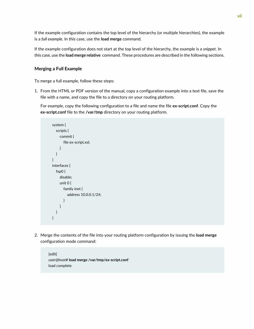
1. From the HTML or PDF version of the manual, copy a configuration example into a text file, save thefile with a name, and copy the file to a directory on your routing platform.
For example, copy the following configuration to a file and name the file ex-script.conf. Copy theex-script.conf file to the /var/tmp directory on your routing platform.
system {scripts {commit {file ex-script.xsl;
}}
}interfaces {fxp0 {disable;unit 0 {family inet {address 10.0.0.1/24;
}}
}}
2. Merge the contents of the file into your routing platform configuration by issuing the load mergeconfiguration mode command:
[edit]user@host# load merge /var/tmp/ex-script.confload complete
xii
Merging a Snippet
To merge a snippet, follow these steps:
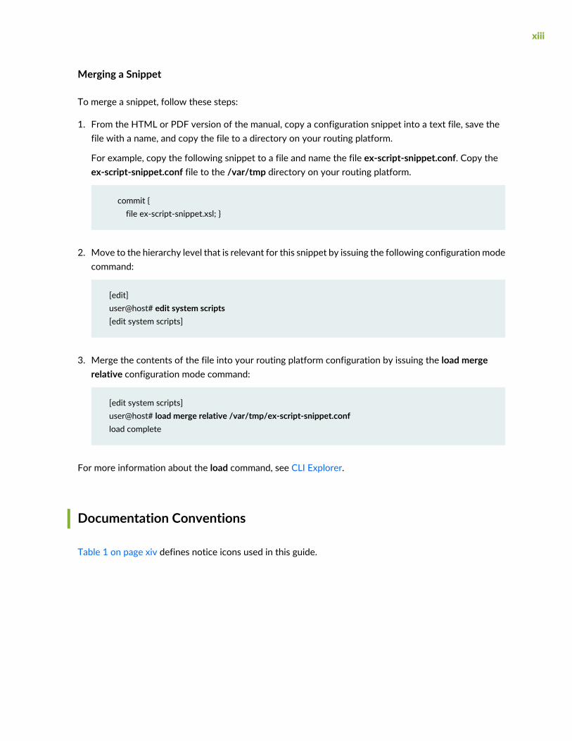
1. From the HTML or PDF version of the manual, copy a configuration snippet into a text file, save thefile with a name, and copy the file to a directory on your routing platform.
For example, copy the following snippet to a file and name the file ex-script-snippet.conf. Copy theex-script-snippet.conf file to the /var/tmp directory on your routing platform.
commit {file ex-script-snippet.xsl; }
2. Move to the hierarchy level that is relevant for this snippet by issuing the following configurationmodecommand:
[edit]user@host# edit system scripts[edit system scripts]
3. Merge the contents of the file into your routing platform configuration by issuing the load mergerelative configuration mode command:
[edit system scripts]user@host# load merge relative /var/tmp/ex-script-snippet.confload complete
For more information about the load command, see CLI Explorer.
Documentation Conventions
Table 1 on page xiv defines notice icons used in this guide.
xiii
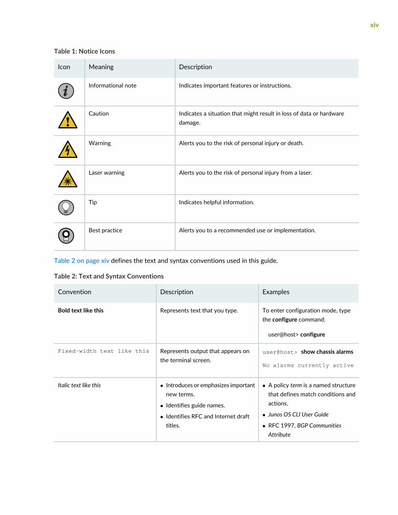
Table 1: Notice Icons
DescriptionMeaningIcon
Indicates important features or instructions.Informational note
Indicates a situation that might result in loss of data or hardwaredamage.
Caution
Alerts you to the risk of personal injury or death.Warning
Alerts you to the risk of personal injury from a laser.Laser warning
Indicates helpful information.Tip
Alerts you to a recommended use or implementation.Best practice
Table 2 on page xiv defines the text and syntax conventions used in this guide.
Table 2: Text and Syntax Conventions
ExamplesDescriptionConvention
To enter configuration mode, typethe configure command:
user@host> configure
Represents text that you type.Bold text like this
user@host> show chassis alarms
No alarms currently active
Represents output that appears onthe terminal screen.
Fixed-width text like this
• A policy term is a named structurethat defines match conditions andactions.
• Junos OS CLI User Guide
• RFC 1997, BGP CommunitiesAttribute
• Introduces or emphasizes importantnew terms.
• Identifies guide names.
• Identifies RFC and Internet drafttitles.
Italic text like this
xiv
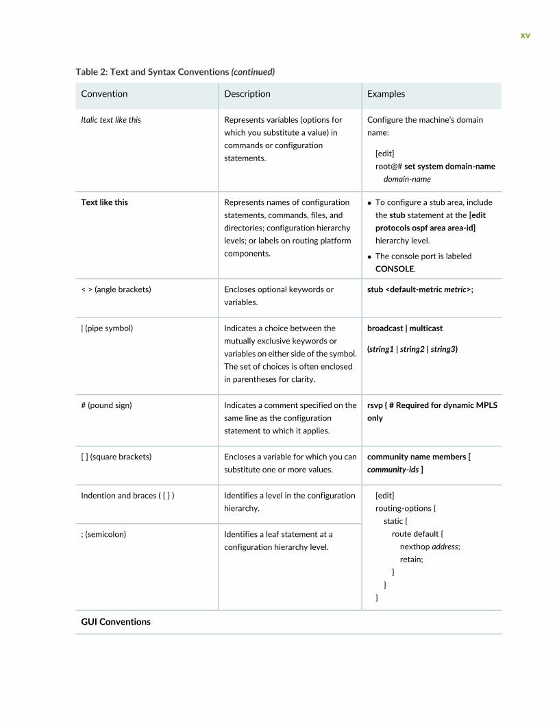
Table 2: Text and Syntax Conventions (continued)
ExamplesDescriptionConvention
Configure the machine’s domainname:
[edit]root@# set system domain-namedomain-name
Represents variables (options forwhich you substitute a value) incommands or configurationstatements.
Italic text like this
• To configure a stub area, includethe stub statement at the [editprotocols ospf area area-id]hierarchy level.
• The console port is labeledCONSOLE.
Represents names of configurationstatements, commands, files, anddirectories; configuration hierarchylevels; or labels on routing platformcomponents.
Text like this
stub <default-metric metric>;Encloses optional keywords orvariables.
< > (angle brackets)
broadcast | multicast
(string1 | string2 | string3)
Indicates a choice between themutually exclusive keywords orvariables on either side of the symbol.The set of choices is often enclosedin parentheses for clarity.
| (pipe symbol)
rsvp { # Required for dynamic MPLSonly
Indicates a comment specified on thesame line as the configurationstatement to which it applies.
# (pound sign)
community name members [community-ids ]
Encloses a variable for which you cansubstitute one or more values.
[ ] (square brackets)
[edit]routing-options {static {route default {nexthop address;retain;
}}
}
Identifies a level in the configurationhierarchy.
Indention and braces ( { } )
Identifies a leaf statement at aconfiguration hierarchy level.
; (semicolon)
GUI Conventions
xv
Table 2: Text and Syntax Conventions (continued)
ExamplesDescriptionConvention
• In the Logical Interfaces box, selectAll Interfaces.
• To cancel the configuration, clickCancel.
Represents graphical user interface(GUI) items you click or select.
Bold text like this
In the configuration editor hierarchy,select Protocols>Ospf.
Separates levels in a hierarchy ofmenu selections.
> (bold right angle bracket)
Documentation Feedback
We encourage you to provide feedback so that we can improve our documentation. You can use eitherof the following methods:
• Online feedback system—Click TechLibrary Feedback, on the lower right of any page on the JuniperNetworks TechLibrary site, and do one of the following:
• Click the thumbs-up icon if the information on the page was helpful to you.
• Click the thumbs-down icon if the information on the page was not helpful to you or if you havesuggestions for improvement, and use the pop-up form to provide feedback.
• E-mail—Send your comments to [email protected]. Include the document or topic name,URL or page number, and software version (if applicable).
Requesting Technical Support
Technical product support is available through the Juniper Networks Technical Assistance Center (JTAC).If you are a customer with an active Juniper Care or Partner Support Services support contract, or are
xvi

covered under warranty, and need post-sales technical support, you can access our tools and resourcesonline or open a case with JTAC.
• JTAC policies—For a complete understanding of our JTAC procedures and policies, review the JTACUserGuide located at https://www.juniper.net/us/en/local/pdf/resource-guides/7100059-en.pdf.
• Productwarranties—For productwarranty information, visit https://www.juniper.net/support/warranty/.
• JTAC hours of operation—The JTAC centers have resources available 24 hours a day, 7 days a week,365 days a year.
Self-Help Online Tools and Resources
For quick and easy problem resolution, Juniper Networks has designed an online self-service portal calledthe Customer Support Center (CSC) that provides you with the following features:
• Find CSC offerings: https://www.juniper.net/customers/support/
• Search for known bugs: https://prsearch.juniper.net/
• Find product documentation: https://www.juniper.net/documentation/
• Find solutions and answer questions using our Knowledge Base: https://kb.juniper.net/
• Download the latest versions of software and review release notes:https://www.juniper.net/customers/csc/software/
• Search technical bulletins for relevant hardware and software notifications:https://kb.juniper.net/InfoCenter/
• Join and participate in the Juniper Networks Community Forum:https://www.juniper.net/company/communities/
• Create a service request online: https://myjuniper.juniper.net
To verify service entitlement by product serial number, use our Serial Number Entitlement (SNE) Tool:https://entitlementsearch.juniper.net/entitlementsearch/
Creating a Service Request with JTAC
You can create a service request with JTAC on the Web or by telephone.
• Visit https://myjuniper.juniper.net.
• Call 1-888-314-JTAC (1-888-314-5822 toll-free in the USA, Canada, and Mexico).
For international or direct-dial options in countries without toll-free numbers, seehttps://support.juniper.net/support/requesting-support/.
xvii

1CHAPTER
Overview
EX3400 System Overview | 19
EX3400 Chassis | 28
EX3400 Cooling System | 38
EX3400 Power System | 41

EX3400 System Overview
IN THIS SECTION
EX3400 Switches Hardware Overview | 19
EX3400 Switch Models | 22
EX3400 Switch Hardware and CLI Terminology Mapping | 23
Chassis Physical Specifications for EX3400 Switches | 26
Field-Replaceable Units in EX3400 Switches | 27
EX3400 Switches Hardware Overview
IN THIS SECTION
Benefits of the EX3400 Switch | 19
EX3400 Switches First View | 20
Uplink Ports | 20
Virtual Chassis | 21
Console Ports | 21
Power over Ethernet Ports | 21
Juniper Networks EX Series Ethernet Switches provide scalable connectivity for the enterprise market,including branch offices, campus locations, and data centers. The switches run the Juniper Networks Junosoperating system (Junos OS), which provides Layer 2 and Layer 3 switching, routing, and security services.
Juniper Networks EX3400 Ethernet Switches provide connectivity for low-density environments.
Benefits of the EX3400 Switch
High flexibility—EX3400 switches provide a flexible solution that supports converged data, voice, andvideo environments.
19

Support for MACsec—EX3400 switches support IEEE 802.1AE MACsec, providing support for link-layerdata confidentiality, data integrity, and data origin authentication. The MACsec feature enables EX3400to support 88Gbps of near line-rate hardware-based traffic encryption on all Gigabit Ethernet and 10GigabitEthernet ports.
Nondisruptive software upgrades—EX3400 switches feature a resilient operating system that supportshigh availability (HA) features such as graceful Routing Engine switchover (GRES), nonstop active routing(NSR), and nonstop software upgrade (NSSU), providing software upgrades and changes without disruptingnetwork traffic.
EX3400 Switches First View
EX3400 switches provide:
• Either 24 or 48 RJ-45 ports (labeled 0 through 23 or 0 through 47) that support 10/100/1000BASE-TGigabit Ethernet connectors.
• Four uplink ports (labeled 0 through 3 on the front panel) that support small form-factor pluggable (SFP)transceivers and small form-factor pluggable plus (SFP+) transceivers, and two 40-Gigabit Ethernet ports(labeled 0 through 1 on the rear panel) that support quad small form-factor pluggable plus (QSFP+)transceivers.
• Virtual Chassis capability—You can connect up to 10 EX3400 switches together to form one unit thatyou manage as a single chassis, called a Virtual Chassis.
• Power over Ethernet (PoE) or Power over Ethernet plus (PoE+) on all RJ-45 ports (in PoE-capablemodels).
Uplink Ports
EX3400 switches have autosensing uplink ports that you can use to:
• Connect an access switch to a distribution switch
• Interconnect member switches of a Virtual Chassis
The QSFP+ uplink ports are configured as Virtual Chassis ports (VCPs) by default. You can use these portsto interconnect Virtual Chassis members. To use the QSFP+ uplink ports as network ports, you mustconfigure them as network ports. The uplink ports on the front panel are configured as network ports bydefault. To use the uplink ports on the front panel as VCPs, you must configure them as VCPs. See Settingan Uplink Port on an EX Series or QFX Series Switch as a Virtual Chassis Port.
The uplink ports on the front panel support four 1-gigabit SFP transceivers, four 10-gigabit SFP+transceivers, or a combination of four SFP+ and SFP transceivers. TheQSFP+ uplink ports support 40-gigabitQSFP+ transceivers. For a list of supported transceivers, see “Pluggable Transceivers Supported on EX3400Switches” on page 66.
20
NOTE: You cannot form a Virtual Chassis by using SFP transceivers.
Virtual Chassis
You can interconnect a maximum of 10 EX3400 switches to form a Virtual Chassis. You can operate theseinterconnected switches as a single, logical device with a single IP address.
You can use the following ports to interconnect an EX3400 switch in a Virtual Chassis:
• QSFP+ ports configured as VCPs by using QSFP+ transceivers
•NOTE: You cannot form a Virtual Chassis by using SFP transceivers.
Uplink ports on the front panel configured as VCPs by using SFP+ transceivers
By default, the QSFP+ ports are configured as VCPs.
Console Ports
EX3400 switches have two console ports—an RJ-45 console port and a Mini-USB Type-B console port.The RJ-45 console port is on the rear panel of the switch and the mini-USB console port is on the frontpanel. Both console ports are labeled CON. The RJ-45 console port accepts a cable that has an RJ-45connector and the Mini-USB Type-B console port accepts a Mini-B plug (5-pin) connector to connect tothe console management device.
Power over Ethernet Ports
EX3400 switches are available with or without Power over Ethernet (PoE) or Power over Ethernet Plus(PoE+) capability. Models that support PoE or PoE+ provide that support on all RJ-45 ports. PoE portsprovide electrical current to devices—such as IP phones, wireless access points, and securitycameras—through network cables, thus eliminating the need for separate power cords for those devices.
NOTE: IEEE 802.3at class 4 powered devices require category 5 or higher Ethernet cables.
The remainder of this documentation uses the term PoE for both PoE and PoE+ unless there is a need todistinguish between the two.
21
EX3400 Switch Models
EX3400 switch models are available:
• With 24 or 48 RJ-45 ports
• With or without PoE+ capability
• With front-to-back or back-to-front airflow
• With AC or DC power supplies
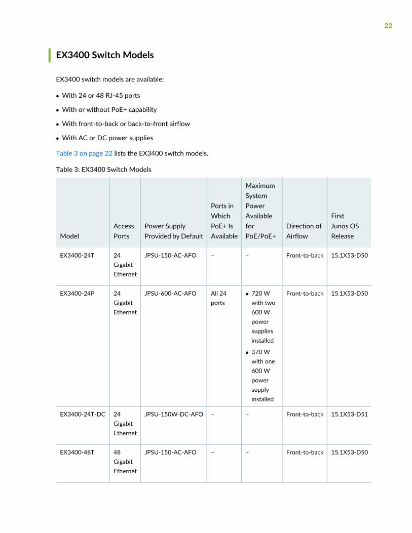
Table 3 on page 22 lists the EX3400 switch models.
Table 3: EX3400 Switch Models
FirstJunos OSRelease
Direction ofAirflow
MaximumSystemPowerAvailableforPoE/PoE+
Ports inWhichPoE+ IsAvailable
Power SupplyProvided by Default
AccessPortsModel
15.1X53-D50Front-to-back––JPSU-150-AC-AFO24GigabitEthernet
EX3400-24T
15.1X53-D50Front-to-back• 720 Wwith two600 Wpowersuppliesinstalled
• 370 Wwith one600 Wpowersupplyinstalled
All 24ports
JPSU-600-AC-AFO24GigabitEthernet
EX3400-24P
15.1X53-D51Front-to-back––JPSU-150W-DC-AFO24GigabitEthernet
EX3400-24T-DC
15.1X53-D50Front-to-back––JPSU-150-AC-AFO48GigabitEthernet
EX3400-48T
22
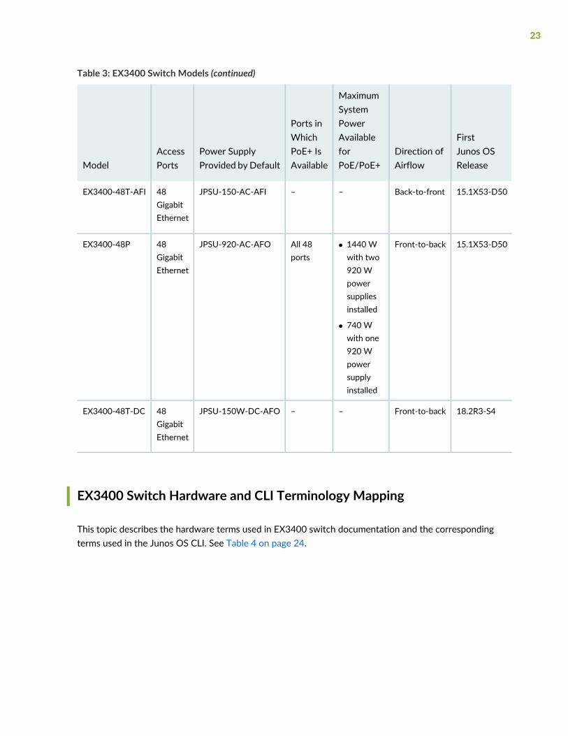
Table 3: EX3400 Switch Models (continued)
FirstJunos OSRelease
Direction ofAirflow
MaximumSystemPowerAvailableforPoE/PoE+
Ports inWhichPoE+ IsAvailable
Power SupplyProvided by Default
AccessPortsModel
15.1X53-D50Back-to-front––JPSU-150-AC-AFI48GigabitEthernet
EX3400-48T-AFI
15.1X53-D50Front-to-back• 1440 Wwith two920 Wpowersuppliesinstalled
• 740 Wwith one920 Wpowersupplyinstalled
All 48ports
JPSU-920-AC-AFO48GigabitEthernet
EX3400-48P
18.2R3-S4Front-to-back––JPSU-150W-DC-AFO48GigabitEthernet
EX3400-48T-DC
EX3400 Switch Hardware and CLI Terminology Mapping
This topic describes the hardware terms used in EX3400 switch documentation and the correspondingterms used in the Junos OS CLI. See Table 4 on page 24.
23
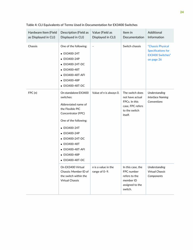
Table 4: CLI Equivalents of Terms Used in Documentation for EX3400 Switches
AdditionalInformation
Item inDocumentation
Value (Field asDisplayed in CLI)
Description (Field asDisplayed in CLI)
Hardware Item (Fieldas Displayed in CLI)
“Chassis PhysicalSpecifications forEX3400 Switches”on page 26
Switch chassis–One of the following:
• EX3400-24T
• EX3400-24P
• EX3400-24T-DC
• EX3400-48T
• EX3400-48T-AFI
• EX3400-48P
• EX3400-48T-DC
Chassis
UnderstandingInterface NamingConventions
The switch doesnot have actualFPCs. In thiscase, FPC refersto the switchitself.
Value of n is always 0.On standalone EX3400switches:
Abbreviated name ofthe Flexible PICConcentrator (FPC)
One of the following:
• EX3400-24T
• EX3400-24P
• EX3400-24T-DC
• EX3400-48T
• EX3400-48T-AFI
• EX3400-48P
• EX3400-48T-DC
FPC (n)
UnderstandingVirtual ChassisComponents
In this case, theFPC numberrefers to themember IDassigned to theswitch.
n is a value in therange of 0–9.
On EX3400 VirtualChassis: Member ID ofthe switch within theVirtual Chassis
24
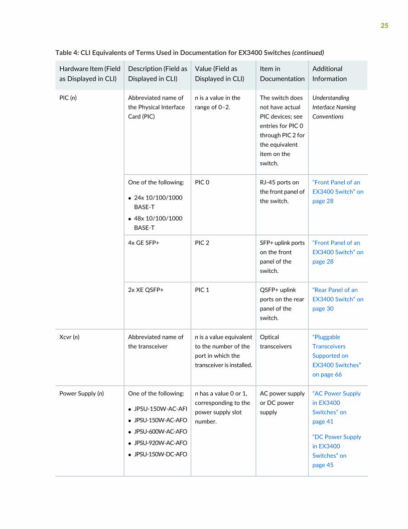
Table 4: CLI Equivalents of Terms Used in Documentation for EX3400 Switches (continued)
AdditionalInformation
Item inDocumentation
Value (Field asDisplayed in CLI)
Description (Field asDisplayed in CLI)
Hardware Item (Fieldas Displayed in CLI)
UnderstandingInterface NamingConventions
The switch doesnot have actualPIC devices; seeentries for PIC 0through PIC 2 forthe equivalentitem on theswitch.
n is a value in therange of 0–2.
Abbreviated name ofthe Physical InterfaceCard (PIC)
PIC (n)
“Front Panel of anEX3400 Switch” onpage 28
RJ-45 ports onthe front panel ofthe switch.
PIC 0One of the following:
• 24x 10/100/1000BASE-T
• 48x 10/100/1000BASE-T
“Front Panel of anEX3400 Switch” onpage 28
SFP+ uplink portson the frontpanel of theswitch.
PIC 24x GE SFP+
“Rear Panel of anEX3400 Switch” onpage 30
QSFP+ uplinkports on the rearpanel of theswitch.
PIC 12x XE QSFP+
“PluggableTransceiversSupported onEX3400 Switches”on page 66
Opticaltransceivers
n is a value equivalentto the number of theport in which thetransceiver is installed.
Abbreviated name ofthe transceiver
Xcvr (n)
“AC Power Supplyin EX3400Switches” onpage 41
“DC Power Supplyin EX3400Switches” onpage 45
AC power supplyor DC powersupply
n has a value 0 or 1,corresponding to thepower supply slotnumber.
One of the following:
• JPSU-150W-AC-AFI
• JPSU-150W-AC-AFO
• JPSU-600W-AC-AFO
• JPSU-920W-AC-AFO
• JPSU-150W-DC-AFO
Power Supply (n)
25
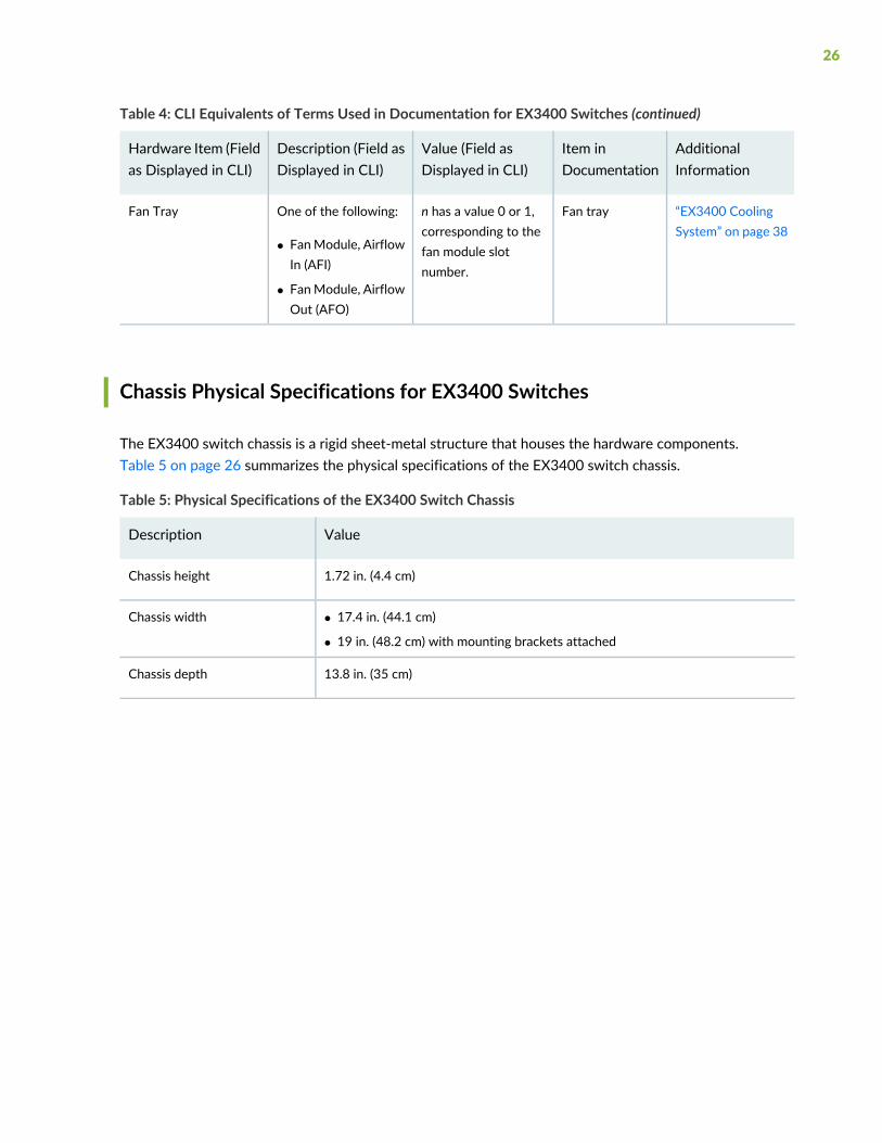
Table 4: CLI Equivalents of Terms Used in Documentation for EX3400 Switches (continued)
AdditionalInformation
Item inDocumentation
Value (Field asDisplayed in CLI)
Description (Field asDisplayed in CLI)
Hardware Item (Fieldas Displayed in CLI)
“EX3400 CoolingSystem” on page 38
Fan trayn has a value 0 or 1,corresponding to thefan module slotnumber.
One of the following:
• FanModule, AirflowIn (AFI)
• FanModule, AirflowOut (AFO)
Fan Tray
Chassis Physical Specifications for EX3400 Switches
The EX3400 switch chassis is a rigid sheet-metal structure that houses the hardware components.Table 5 on page 26 summarizes the physical specifications of the EX3400 switch chassis.
Table 5: Physical Specifications of the EX3400 Switch Chassis
ValueDescription
1.72 in. (4.4 cm)Chassis height
• 17.4 in. (44.1 cm)
• 19 in. (48.2 cm) with mounting brackets attached
Chassis width
13.8 in. (35 cm)Chassis depth
26

Table 5: Physical Specifications of the EX3400 Switch Chassis (continued)
ValueDescription
• EX3400-24T (without power supply or fanmodules installed): 9.755 lb (4.425 kg)
• EX3400-24T-DC (without power supply or fan modules installed): 9.755 lb(4.425 kg)
• EX3400-24P (without power supply or fan modules installed): 9.965 lb (4.52 kg)
• EX3400-48T (without power supply or fanmodules installed): 10.227 lb (4.639 kg)
• EX3400-48T-AFI (without power supply or fan modules installed): 10.238 lb(4.644 kg)
• EX3400-48P (without power supply or fanmodules installed): 10.49 lb (4.758 kg)
• EX3400-48T-DC (without power supply or fan modules installed): 10.227 lb(4.639 kg)
• JPSU-150-AC-AFO: 1.433 lb (0.65 kg)
• JPSU-150-AC-AFI: 1.433 lb (0.65 kg)
• JPSU-600-AC-AFO: 1.823 lb (0.827 kg)
• JPSU-920-AC-AFO: 1.874 lb (0.85 kg)
• JPSU-150W-DC-AFO: 1.433 lb (0.65 kg)
Weight
SEE ALSO
Installing and Connecting an EX3400 Switch | 95
Field-Replaceable Units in EX3400 Switches
Field-replaceable units (FRUs) are components that you can replace at your site. The FRUs in EX3400switches are hot-removable and hot-insertable: You can remove and replace them without powering offthe switch. The FRUs in EX3400 switches are:
• Power supplies
• Fan modules
• Transceivers
27

NOTE: If you have a Juniper J-Care service contract, register any addition, change, or upgradeof hardware components at https://www.juniper.net/customers/support/tools/updateinstallbase/.Failure to do so can result in significant delays if you need replacement parts. This note doesnot apply if you replace existing components with the same type of component.
EX3400 Chassis
IN THIS SECTION
Front Panel of an EX3400 Switch | 28
Rear Panel of an EX3400 Switch | 30
Chassis Status LEDs in EX3400 Switches | 31
Management Port LEDs in EX3400 Switches | 33
RJ-45 Network Port and Uplink Port LEDs in EX3400 Switches | 34
Front Panel of an EX3400 Switch
The front panel of an EX3400 switch consists of the following components:
• RJ-45 ports:
• Depending on the switch model, 24 or 48 RJ-45 ports (labeled 0 through 23 or 0 through 47) thatsupport 10/100/1000BASE-T Gigabit Ethernet connectors
• PoE available in all RJ-45 ports in EX3400-24P and EX3400-48P models
• PoEnot available in any network port in EX3400-24T, EX3400-24T-DC, EX3400-48T, EX3400-48T-AFI,and EX3400-48T-DC models
• Three chassis status LEDs
• Four port status mode LEDs in models with PoE capability and three port status mode LEDs in modelswithout PoE capability
• One Factory Reset/Mode button
28
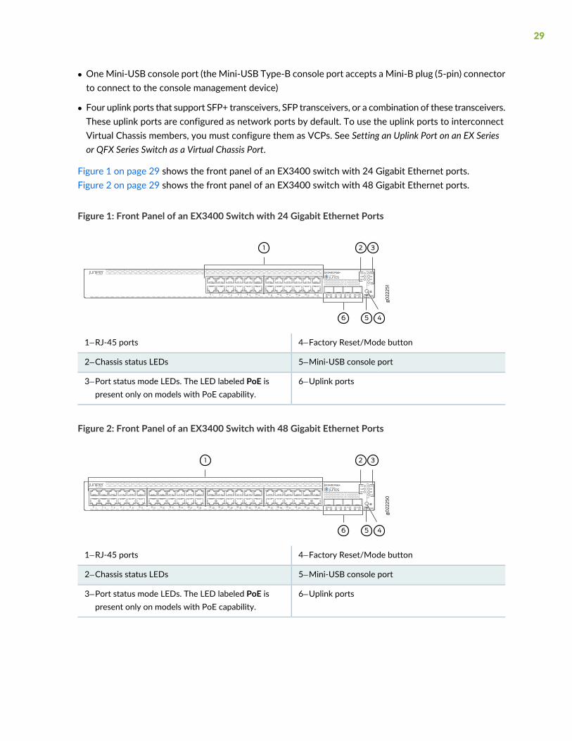
• OneMini-USB console port (the Mini-USB Type-B console port accepts a Mini-B plug (5-pin) connectorto connect to the console management device)
• Four uplink ports that support SFP+ transceivers, SFP transceivers, or a combination of these transceivers.These uplink ports are configured as network ports by default. To use the uplink ports to interconnectVirtual Chassis members, you must configure them as VCPs. See Setting an Uplink Port on an EX Seriesor QFX Series Switch as a Virtual Chassis Port.
Figure 1 on page 29 shows the front panel of an EX3400 switch with 24 Gigabit Ethernet ports.Figure 2 on page 29 shows the front panel of an EX3400 switch with 48 Gigabit Ethernet ports.
Figure 1: Front Panel of an EX3400 Switch with 24 Gigabit Ethernet Ports
4—1— Factory Reset/Mode buttonRJ-45 ports
5—2— Mini-USB console portChassis status LEDs
6—3— Uplink portsPort status mode LEDs. The LED labeled PoE ispresent only on models with PoE capability.
Figure 2: Front Panel of an EX3400 Switch with 48 Gigabit Ethernet Ports
4—1— Factory Reset/Mode buttonRJ-45 ports
5—2— Mini-USB console portChassis status LEDs
6—3— Uplink portsPort status mode LEDs. The LED labeled PoE ispresent only on models with PoE capability.
29

Rear Panel of an EX3400 Switch
The rear panel of the EX3400 switch consists of the following components:
• 1 USB port
• 1 management Ethernet port that supports an RJ-45 connector
• 1 RJ-45 console port (the RJ-45 console port accepts a cable with an RJ-45 connector to connect to theconsole management device)
• 1 protective earthing terminal
• 2 QSFP+ uplink ports. These uplink ports are configured as Virtual Chassis ports (VCPs) by default. Youcan use these uplink ports to interconnect Virtual Chassis members. To use the QSFP+ uplink ports asnetwork ports, you must configure them as network ports.
• 1 ESD point
• 2 fan modules
• CLEI code label
• Serial Number ID Label
• 1 AC power supply or DC power supply
• Empty slot for power supply covered by a blank panel or DC power supply
Figure 3 on page 30 shows the rear panel of an EX3400 switch with AC power supply.
The power cord retainer extends out of the chassis by 3 in. (7.62 cm). The fan module handle extends outof the chassis by 1.2 in. (3 cm).
Figure 3: Rear Panel of an EX3400 Switch with an AC Power Supply
7—1— Fan modulesUSB port
8—2— CLEI code labelManagement Ethernet port
9—3— Serial Number ID LabelRJ-45 console port
10—4— AC power supplyProtective earthing terminal
11—5— Empty slot for power supply covered by a blank panelQSFP+ uplink ports
6—ESD point
30
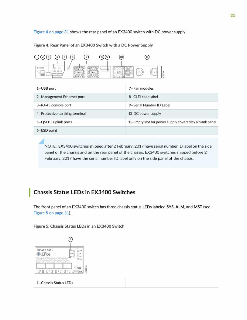
Figure 4 on page 31 shows the rear panel of an EX3400 switch with DC power supply.
Figure 4: Rear Panel of an EX3400 Switch with a DC Power Supply
7—1— Fan modulesUSB port
8—2— CLEI code labelManagement Ethernet port
9—3— Serial Number ID LabelRJ-45 console port
10—4— DC power supplyProtective earthing terminal
11—5— Empty slot for power supply covered by a blank panelQSFP+ uplink ports
6—ESD point
NOTE: EX3400 switches shipped after 2 February, 2017 have serial number ID label on the sidepanel of the chassis and on the rear panel of the chassis. EX3400 switches shipped before 2February, 2017 have the serial number ID label only on the side panel of the chassis.
Chassis Status LEDs in EX3400 Switches
The front panel of an EX3400 switch has three chassis status LEDs labeled SYS, ALM, andMST (seeFigure 5 on page 31).
Figure 5: Chassis Status LEDs in an EX3400 Switch
1—Chassis Status LEDs
31
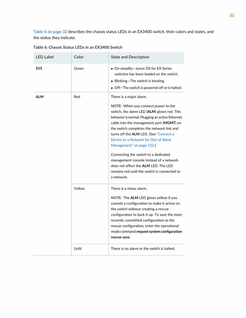
Table 6 on page 32 describes the chassis status LEDs in an EX3400 switch, their colors and states, andthe status they indicate.
Table 6: Chassis Status LEDs in an EX3400 Switch
State and DescriptionColorLED Label
• On steadily—Junos OS for EX Seriesswitches has been loaded on the switch.
• Blinking—The switch is booting.
• Off—The switch is powered off or is halted.
GreenSYS
There is a major alarm.
NOTE: When you connect power to theswitch, the alarm LED (ALM) glows red. Thisbehavior is normal. Plugging an active Ethernetcable into the management port (MGMT) onthe switch completes the network link andturns off the ALM LED. (See “Connect aDevice to a Network for Out-of-BandManagement” on page 122.)
Connecting the switch to a dedicatedmanagement console instead of a networkdoes not affect the ALM LED. The LEDremains red until the switch is connected toa network.
RedALM
There is a minor alarm.
NOTE: The ALM LED glows yellow if youcommit a configuration to make it active onthe switch without creating a rescueconfiguration to back it up. To save the mostrecently committed configuration as therescue configuration, enter the operationalmode command request systemconfigurationrescue save.
Yellow
There is no alarm or the switch is halted.Unlit
32

Table 6: Chassis Status LEDs in an EX3400 Switch (continued)
State and DescriptionColorLED Label
In a standalone EX3400 switch:
• On steadily—The switch is functioningnormally as the primary.
• Off—The switch is powered off or is halted.
In a Virtual Chassis configuration:
• On steadily—The switch is functioningnormally and is the primary in the VirtualChassis configuration.
• Blinking—The switch is functioning normallyand is the backup in the Virtual Chassisconfiguration.
• Off—The switch is a linecardmember in theVirtual Chassis configuration or is halted.
GreenMST
A major alarm (red) indicates a critical error condition that requires immediate action.
A minor alarm (yellow) indicates a noncritical condition that requires monitoring or maintenance. A minoralarm that is left unchecked might cause interruption in service or performance degradation.
All three LEDs can be lit simultaneously.
You can view the colors of the two LEDs remotely through the CLI by issuing the operational modecommand show chassis led.
SEE ALSO
Understand Alarm Types and Severity Levels on EX Series Switches | 215
Management Port LEDs in EX3400 Switches
The management port, which is on the rear panel of an EX3400 switch, has two LEDs that indicatelink/activity and port status (see Figure 6 on page 34).
33
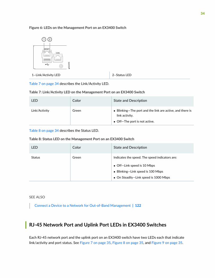
Figure 6: LEDs on the Management Port on an EX3400 Switch
2—1— Status LEDLink/Activity LED
Table 7 on page 34 describes the Link/Activity LED.
Table 7: Link/Activity LED on the Management Port on an EX3400 Switch
State and DescriptionColorLED
• Blinking—The port and the link are active, and there islink activity.
• Off—The port is not active.
GreenLink/Activity
Table 8 on page 34 describes the Status LED.
Table 8: Status LED on the Management Port on an EX3400 Switch
State and DescriptionColorLED
Indicates the speed. The speed indicators are:
• Off—Link speed is 10 Mbps
• Blinking—Link speed is 100 Mbps
• On Steadily—Link speed is 1000 Mbps
GreenStatus
SEE ALSO
Connect a Device to a Network for Out-of-Band Management | 122
RJ-45 Network Port and Uplink Port LEDs in EX3400 Switches
Each RJ-45 network port and the uplink port on an EX3400 switch have two LEDs each that indicatelink/activity and port status. See Figure 7 on page 35, Figure 8 on page 35, and Figure 9 on page 35.
34
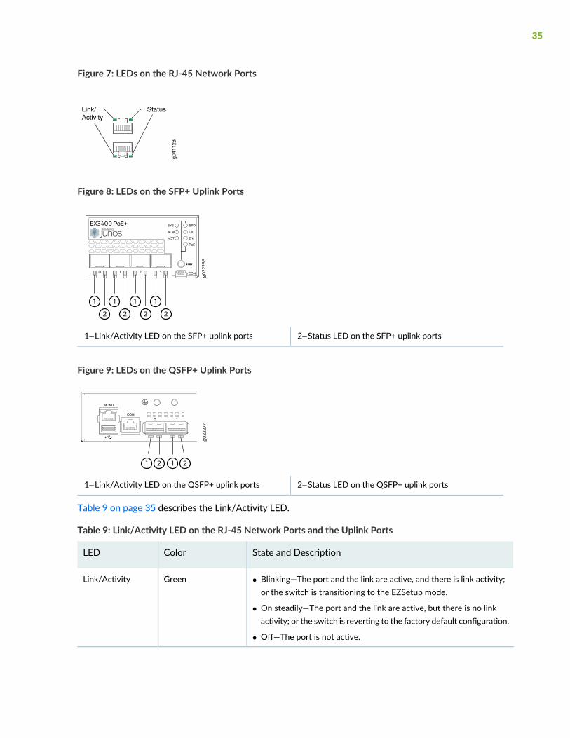
Figure 7: LEDs on the RJ-45 Network Ports
g041
128
Link/Activity
Status
Figure 8: LEDs on the SFP+ Uplink Ports
2—1— Status LED on the SFP+ uplink portsLink/Activity LED on the SFP+ uplink ports
Figure 9: LEDs on the QSFP+ Uplink Ports
2—1— Status LED on the QSFP+ uplink portsLink/Activity LED on the QSFP+ uplink ports
Table 9 on page 35 describes the Link/Activity LED.
Table 9: Link/Activity LED on the RJ-45 Network Ports and the Uplink Ports
State and DescriptionColorLED
• Blinking—The port and the link are active, and there is link activity;or the switch is transitioning to the EZSetup mode.
• On steadily—The port and the link are active, but there is no linkactivity; or the switch is reverting to the factory default configuration.
• Off—The port is not active.
GreenLink/Activity
35
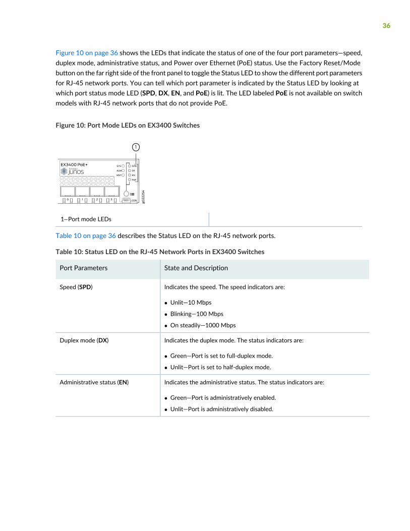
Figure 10 on page 36 shows the LEDs that indicate the status of one of the four port parameters—speed,duplex mode, administrative status, and Power over Ethernet (PoE) status. Use the Factory Reset/Modebutton on the far right side of the front panel to toggle the Status LED to show the different port parametersfor RJ-45 network ports. You can tell which port parameter is indicated by the Status LED by looking atwhich port status mode LED (SPD, DX, EN, and PoE) is lit. The LED labeled PoE is not available on switchmodels with RJ-45 network ports that do not provide PoE.
Figure 10: Port Mode LEDs on EX3400 Switches
1—Port mode LEDs
Table 10 on page 36 describes the Status LED on the RJ-45 network ports.
Table 10: Status LED on the RJ-45 Network Ports in EX3400 Switches
State and DescriptionPort Parameters
Indicates the speed. The speed indicators are:
• Unlit—10 Mbps
• Blinking—100 Mbps
• On steadily—1000 Mbps
Speed (SPD)
Indicates the duplex mode. The status indicators are:
• Green—Port is set to full-duplex mode.
• Unlit—Port is set to half-duplex mode.
Duplex mode (DX)
Indicates the administrative status. The status indicators are:
• Green—Port is administratively enabled.
• Unlit—Port is administratively disabled.
Administrative status (EN)
36
Table 10: Status LED on the RJ-45 Network Ports in EX3400 Switches (continued)
State and DescriptionPort Parameters
Indicates the PoE status. The status indicators for are:
• On steadily—PoE is available on the port, a device that draws power fromthe port is connected to the port, and the device is drawing power from theport.
• Blinking—PoE is available on the port, but no power is drawn from the portbecause of one of the following:
• No device that draws power from the port is connected to the port.
• A device that draws power from the port is connected to the port, butthe device is not drawing any power from the port.
• Unlit—PoE is not available on the port.
NOTE: PoE Status LED is available on the following EX3400 switch models:
• EX3400-24P
• EX3400-48P
PoE status (PoE)
Starting in Junos OS Release 19.4R1, you can use the request chassis beacon command on EX3400switches to identify the switch or a port on the switch. When you execute the command, the status LEDson the RJ-45 network ports blink two times per second irrespective of the mode the ports are operatingin (see How to Locate a Device or Port Using the Chassis Beacon).
The uplink ports operate in full-duplex mode and PoE is not applicable on uplink ports. The Status LED onuplink ports indicate the Speed (SPD) and Administrative status (EN). Table 11 on page 37 describes theStatus LED on the uplink ports.
Table 11: Status LED on the Uplink Ports in EX3400 Switches
State and DescriptionPort Parameters
Indicates the speed and administrative status.
• The indicators for SFP+ uplink ports are:
• On steadily—10 Gbps
• Blinking—1000 Mbps
• Unlit—The port is administratively disabled or the link is down
• The indicators for QSFP+ uplink ports are:
• On steadily—40-Gigabit port is up
• Unlit—40-Gigabit port is down
Status LED
37
You can tell which port parameter is indicated by the Status LED on RJ-45 network ports and uplink portsby issuing the operational mode command show chassis led.
EX3400 Cooling System
IN THIS SECTION
Airflow Direction in EX3400 Switch Models | 38
Front-to-Back Airflow | 39
Back-to-Front Airflow | 39
The cooling system in an EX3400 switch consists of two fans along the rear of the chassis and a fan eachin the power supplies. The fans provide front-to-back or back-to-front chassis cooling depending on theswitch model.
Airflow Direction in EX3400 Switch Models
Table 12 on page 38 shows the different EX3400 switch models and their direction of airflow.
Table 12: Airflow Direction in EX3400 Switch Models
Direction of AirflowModel
Front-to-backEX3400-24T
Front-to-backEX3400-24P
Front-to-backEX3400-24T-DC
Front-to-backEX3400-48T
Back-to-frontEX3400-48T-AFI
Front-to-backEX3400-48P
Front-to-backEX3400-48T-DC
38
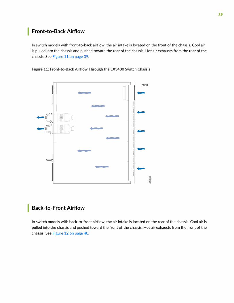
Front-to-Back Airflow
In switch models with front-to-back airflow, the air intake is located on the front of the chassis. Cool airis pulled into the chassis and pushed toward the rear of the chassis. Hot air exhausts from the rear of thechassis. See Figure 11 on page 39.
Figure 11: Front-to-Back Airflow Through the EX3400 Switch Chassis
Back-to-Front Airflow
In switch models with back-to-front airflow, the air intake is located on the rear of the chassis. Cool air ispulled into the chassis and pushed toward the front of the chassis. Hot air exhausts from the front of thechassis. See Figure 12 on page 40.
39
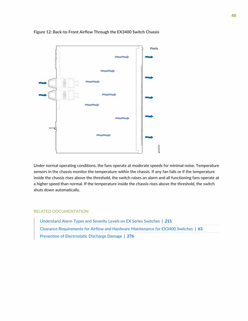
Figure 12: Back-to-Front Airflow Through the EX3400 Switch Chassis
Under normal operating conditions, the fans operate at moderate speeds for minimal noise. Temperaturesensors in the chassis monitor the temperature within the chassis. If any fan fails or if the temperatureinside the chassis rises above the threshold, the switch raises an alarm and all functioning fans operate ata higher speed than normal. If the temperature inside the chassis rises above the threshold, the switchshuts down automatically.
RELATED DOCUMENTATION
Understand Alarm Types and Severity Levels on EX Series Switches | 215
Clearance Requirements for Airflow and Hardware Maintenance for EX3400 Switches | 63
Prevention of Electrostatic Discharge Damage | 276
40
EX3400 Power System
IN THIS SECTION
AC Power Supply in EX3400 Switches | 41
AC Power Supply LEDs in EX3400 Switches | 42
AC Power Cord Specifications for EX3400 Switches | 44
DC Power Supply in EX3400 Switches | 45
DC Power Supply LEDs in EX3400 Switches | 47
Power Specifications for EX3400 Switches | 48
AC Power Supply in EX3400 Switches
The AC power supplies in EX3400 switches are hot-insertable and hot-removable field-replaceable units(FRUs): You can install them without powering off the switch or disrupting the switching function. Theswitch is shipped with one power supply installed.
NOTE: After powering on the switch, wait for at least 60 seconds before powering it off. Afterpowering off the switch, wait for at least 60 seconds before powering it back on.
If only one power supply is installed in your EX3400 switch, you need to power off the switchbefore removing the power supply.
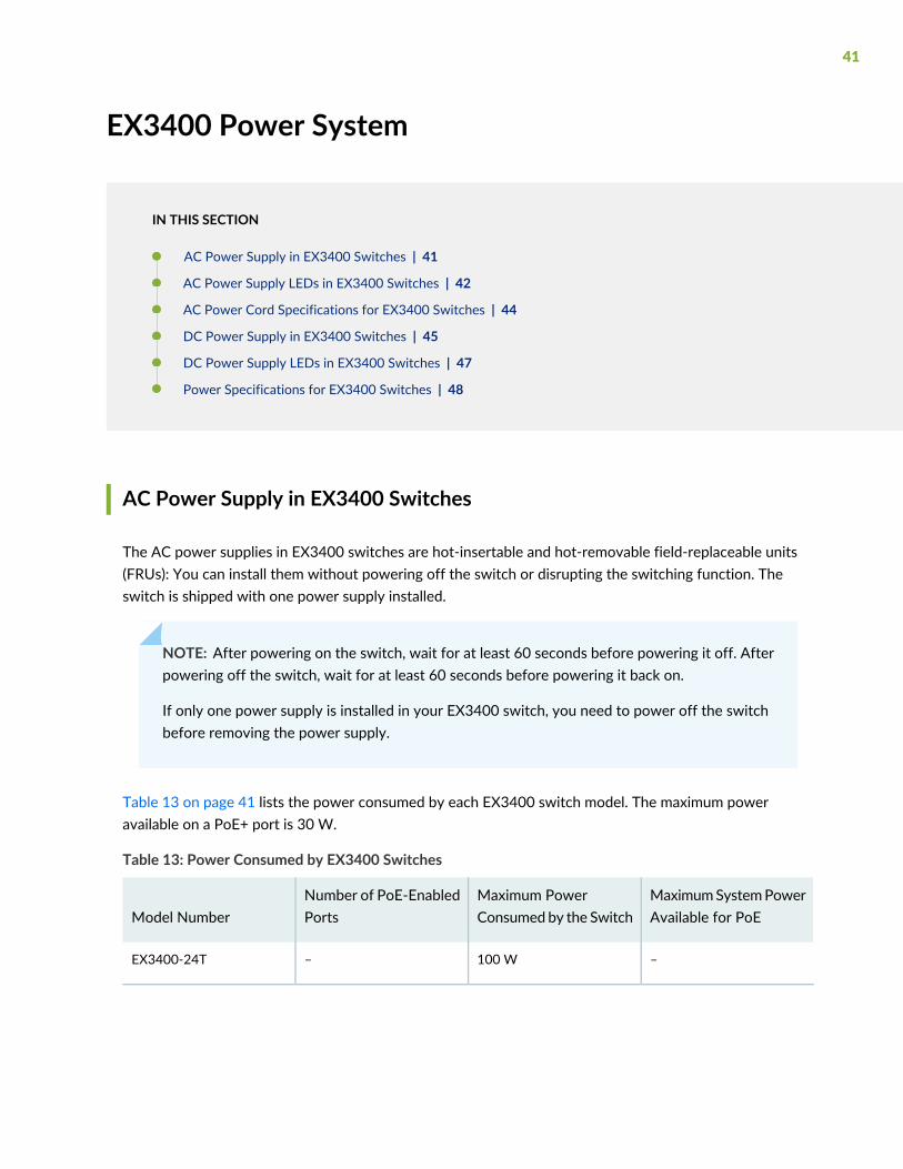
Table 13 on page 41 lists the power consumed by each EX3400 switch model. The maximum poweravailable on a PoE+ port is 30 W.
Table 13: Power Consumed by EX3400 Switches
MaximumSystemPowerAvailable for PoE
Maximum PowerConsumed by the Switch
Number of PoE-EnabledPortsModel Number
–100 W–EX3400-24T
41

Table 13: Power Consumed by EX3400 Switches (continued)
MaximumSystemPowerAvailable for PoE
Maximum PowerConsumed by the Switch
Number of PoE-EnabledPortsModel Number
• 720 W with two 600 Wpower supplies installed
• 370 W with one 600 Wpower supply installed
110 W24EX3400-24P
–120 W–EX3400-48T
–120 W–EX3400-48T-AFI
• 1440Wwith two 920Wpower supplies installed
• 740 W with one 920 Wpower supply installed
120 W48EX3400-48P
NOTE: In EU countries, Egypt, Nigeria, Saudi Arabia, Serbia, South Korea, and South Africa, youmust ensure that the redundant power supply is installed in the switch chassis.
SEE ALSO
Connecting AC Power to an EX3400 Switch | 116
Connecting DC Power to an EX3400 Switch | 118
AC Power Supply LEDs in EX3400 Switches
Figure 13 on page 43 shows the location of the LEDs on an AC power supply for an EX3400 switch.
42
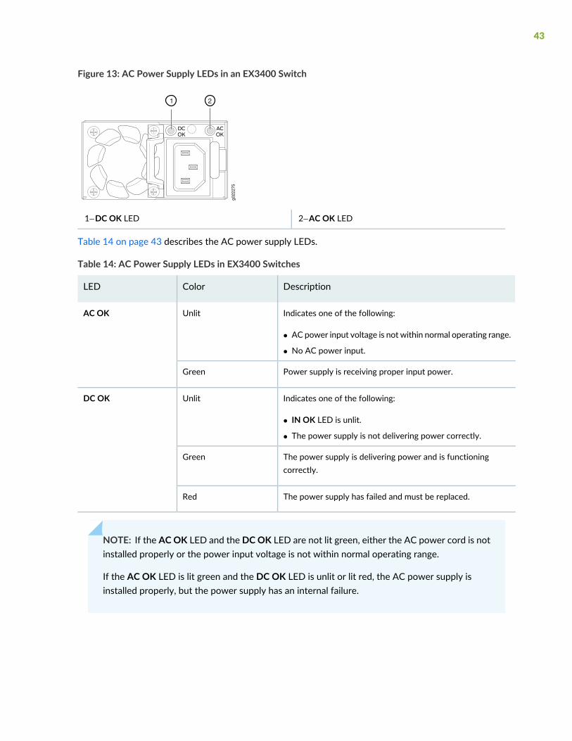
Figure 13: AC Power Supply LEDs in an EX3400 Switch
g022
275
1 2
2—1— AC OK LEDDC OK LED
Table 14 on page 43 describes the AC power supply LEDs.
Table 14: AC Power Supply LEDs in EX3400 Switches
DescriptionColorLED
Indicates one of the following:
• AC power input voltage is not within normal operating range.
• No AC power input.
UnlitAC OK
Power supply is receiving proper input power.Green
Indicates one of the following:
• IN OK LED is unlit.
• The power supply is not delivering power correctly.
UnlitDC OK
The power supply is delivering power and is functioningcorrectly.
Green
The power supply has failed and must be replaced.Red
NOTE: If the ACOK LED and the DCOK LED are not lit green, either the AC power cord is notinstalled properly or the power input voltage is not within normal operating range.
If the AC OK LED is lit green and the DC OK LED is unlit or lit red, the AC power supply isinstalled properly, but the power supply has an internal failure.
43

AC Power Cord Specifications for EX3400 Switches
A detachable AC power cord is supplied with the AC power supplies. The coupler is type C13 as describedby International Electrotechnical Commission (IEC) standard 60320. The plug end of the power cord fitsinto the power source outlet that is standard for your geographical location.
CAUTION: The AC power cord provided with each power supply is intended for usewith that power supply only and not for any other use.
NOTE: In North America, AC power cordsmust not exceed 4.5meters (approximately 14.75 feet)in length, to comply with National Electrical Code (NEC) Sections 400-8 (NFPA 75, 5-2.2) and210-52 and Canadian Electrical Code (CEC) Section 4-010(3). The cords suppliedwith the switchare in compliance.
Table 15 on page 44 gives the AC power cord specifications for the countries and regions listed in thetable.
Table 15: AC Power Cord Specifications
Juniper Model NumberPlug StandardsElectrical SpecificationsCountry/Region
CBL-EX-PWR-C13-ARIRAM 2073 Type RA/3250 VAC, 10 A, 50 HzArgentina
CBL-EX-PWR-C13-AUAS/NZZS 3112 TypeSAA/3
250 VAC, 10 A, 50 HzAustralia
CBL-EX-PWR-C13-BRNBR 14136 Type BR/3250 VAC, 10 A, 50 HzBrazil
CBL-EX-PWR-C13-CHGB1002-1996TypePRC/3250 VAC, 10 A, 50 HzChina
CBL-EX-PWR-C13-EUCEE (7) VII Type VIIG250 VAC, 10 A, 50 HzEurope (except Italy,Switzerland, and UnitedKingdom)
CBL-EX-PWR-C13-INIS 1293 Type IND/3250 VAC, 10 A, 50 HzIndia
CBL-EX-PWR-C13-ILSI 32/1971 Type IL/3G250 VAC, 10 A, 50 HzIsrael
CBL-EX-PWR-C13-ITCEI 23-16 Type I/3G250 VAC, 10 A, 50 HzItaly
44

Table 15: AC Power Cord Specifications (continued)
Juniper Model NumberPlug StandardsElectrical SpecificationsCountry/Region
CBL-EX-PWR-C13-JPSS-00259 Type VCTF125VAC, 12 A, 50Hz or 60Hz
Japan
CBL-EX-PWR-C13-KRCEE (7) VII Type VIIGK250VAC, 10 A, 50Hz or 60Hz
Korea
CBL-EX-PWR-C13-USNEMA 5-15 Type N5-15125 VAC, 13 A, 60 HzNorth America
CBL-PWR-C13-US-48PNEMA 5-15 Type N5-15125 VAC, 15 A, 60 Hz
CBL-EX-PWR-C13-SASABS 164/1:1992 TypeZA/13
250 VAC, 10 A, 50 HzSouth Africa
CBL-EX-PWR-C13-SZSEV 6534-2 Type 12G250 VAC, 10 A, 50 HzSwitzerland
CBL-EX-PWR-C13-TWNEMA5-15PTypeN5-15P125 VAC, 11 A and 15 A,50 Hz
Taiwan
CBL-EX-PWR-C13-UKBS 1363/A Type BS89/13250 VAC, 10 A, 50 HzUnited Kingdom
Figure 14 on page 45 illustrates the plug on the power cord for some of the countries or regions listed inTable 15 on page 44.
Figure 14: AC Plug Types
DC Power Supply in EX3400 Switches
IN THIS SECTION
Characteristics of a DC Power Supply | 46
DC Power Supply Airflow | 47
45
The DC power supplies in EX3400 switches are hot-insertable and hot-removable field-replaceable units(FRUs): You can install them without powering off the switch or disrupting the switching function. Theswitch is shipped with one power supply installed.
NOTE: After powering on the switch, wait for at least 60 seconds before powering it off. Afterpowering off the switch, wait for at least 60 seconds before powering it back on.
If only one power supply is installed in your EX3400 switch, you need to power off the switchbefore removing the power supply.
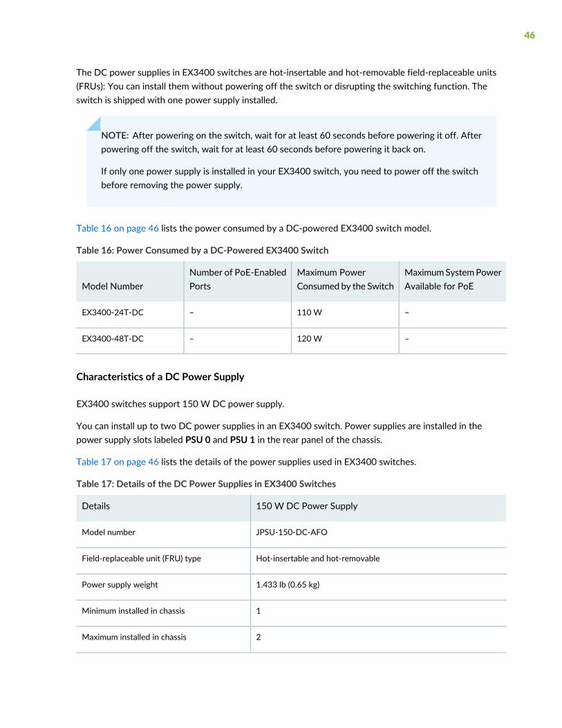
Table 16 on page 46 lists the power consumed by a DC-powered EX3400 switch model.
Table 16: Power Consumed by a DC-Powered EX3400 Switch
MaximumSystemPowerAvailable for PoE
Maximum PowerConsumed by the Switch
Number of PoE-EnabledPortsModel Number
–110 W–EX3400-24T-DC
–120 W–EX3400-48T-DC
Characteristics of a DC Power Supply
EX3400 switches support 150 W DC power supply.
You can install up to two DC power supplies in an EX3400 switch. Power supplies are installed in thepower supply slots labeled PSU 0 and PSU 1 in the rear panel of the chassis.
Table 17 on page 46 lists the details of the power supplies used in EX3400 switches.
Table 17: Details of the DC Power Supplies in EX3400 Switches
150 W DC Power SupplyDetails
JPSU-150-DC-AFOModel number
Hot-insertable and hot-removableField-replaceable unit (FRU) type
1.433 lb (0.65 kg)Power supply weight
1Minimum installed in chassis
2Maximum installed in chassis
46

Table 17: Details of the DC Power Supplies in EX3400 Switches (continued)
150 W DC Power SupplyDetails
Install in power supply slots in the rear panel of the chassis.Power supply slots
InternalFans
Front-to-back, indicated by label AIR OUTAirflow
IN OK and OUT OKPower supply status LEDs
To prevent electrical injury while installing or removing DC power supplies, carefully follow the instructionsgiven in “Installing a DC Power Supply in an EX3400 Switch” on page 202 and “Removing a DC PowerSupply from an EX3400 Switch” on page 200.
DC Power Supply Airflow
Each power supply has its own fan and is cooled by its own internal cooling system.
Each power supply has a label AIR OUT on the faceplate of the power supply that indicates the directionof airflow in the power supply.
Table 18 on page 47 lists the DC power supply models and the direction of airflow in them.
Table 18: Airflow Direction in DC Power Supply Models for EX3400 Switches
Direction of AirflowLabel on Power SupplyModel
Front-to-back—that is, air intake to cool the chassis is throughthe vents on the front panel of the chassis and hot air exhauststhrough the vents on the rear panel of the chassis.
AIR OUTJPSU-150-DC-AFO
DC Power Supply LEDs in EX3400 Switches
Figure 15 on page 48 shows the LEDs on a DC power supply for an EX3400 switch.
47
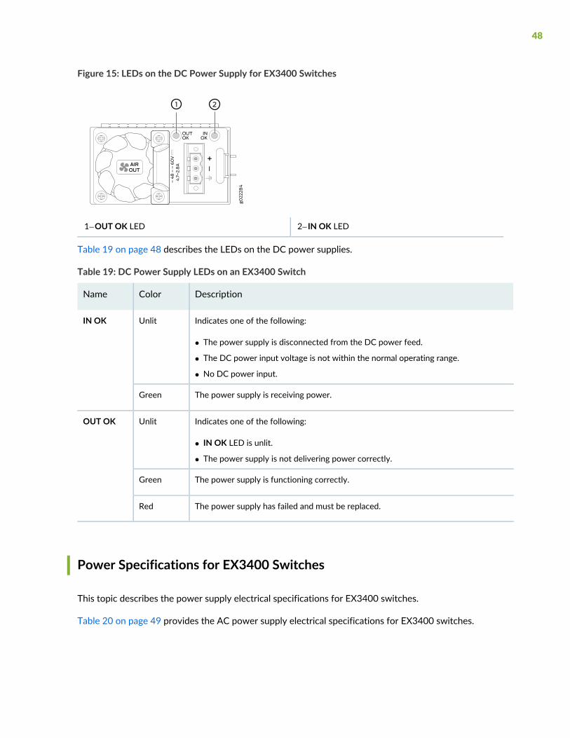
Figure 15: LEDs on the DC Power Supply for EX3400 Switches
2—1— IN OK LEDOUT OK LED
Table 19 on page 48 describes the LEDs on the DC power supplies.
Table 19: DC Power Supply LEDs on an EX3400 Switch
DescriptionColorName
Indicates one of the following:
• The power supply is disconnected from the DC power feed.
• The DC power input voltage is not within the normal operating range.
• No DC power input.
UnlitIN OK
The power supply is receiving power.Green
Indicates one of the following:
• IN OK LED is unlit.
• The power supply is not delivering power correctly.
UnlitOUT OK
The power supply is functioning correctly.Green
The power supply has failed and must be replaced.Red
Power Specifications for EX3400 Switches
This topic describes the power supply electrical specifications for EX3400 switches.
Table 20 on page 49 provides the AC power supply electrical specifications for EX3400 switches.
48
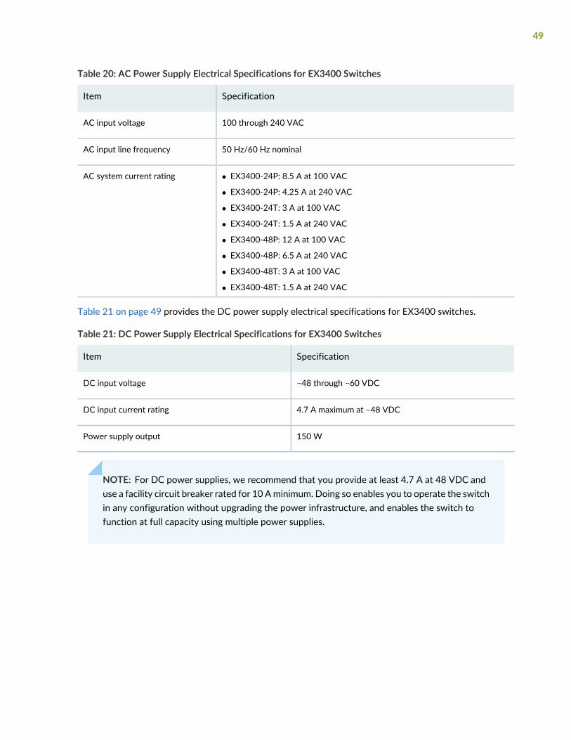
Table 20: AC Power Supply Electrical Specifications for EX3400 Switches
SpecificationItem
100 through 240 VACAC input voltage
50 Hz/60 Hz nominalAC input line frequency
• EX3400-24P: 8.5 A at 100 VAC
• EX3400-24P: 4.25 A at 240 VAC
• EX3400-24T: 3 A at 100 VAC
• EX3400-24T: 1.5 A at 240 VAC
• EX3400-48P: 12 A at 100 VAC
• EX3400-48P: 6.5 A at 240 VAC
• EX3400-48T: 3 A at 100 VAC
• EX3400-48T: 1.5 A at 240 VAC
AC system current rating
Table 21 on page 49 provides the DC power supply electrical specifications for EX3400 switches.
Table 21: DC Power Supply Electrical Specifications for EX3400 Switches
SpecificationItem
–48 through –60 VDCDC input voltage
4.7 A maximum at –48 VDCDC input current rating
150 WPower supply output
NOTE: For DC power supplies, we recommend that you provide at least 4.7 A at 48 VDC anduse a facility circuit breaker rated for 10 Aminimum. Doing so enables you to operate the switchin any configuration without upgrading the power infrastructure, and enables the switch tofunction at full capacity using multiple power supplies.
49

2CHAPTER
Site Planning, Preparation, andSpecifications
Site Preparation Checklist for EX3400 Switches | 51
EX3400 Site Guidelines and Requirements | 54
EX3400 Network Cable and Transceiver Planning | 65
EX3400 Management Cable Specifications and Pinouts | 74
EX3400 Virtual Chassis | 86
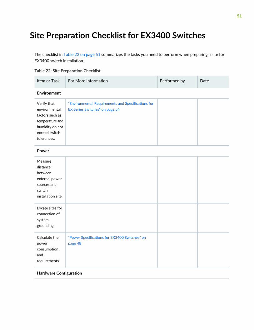
Site Preparation Checklist for EX3400 Switches
The checklist in Table 22 on page 51 summarizes the tasks you need to perform when preparing a site forEX3400 switch installation.
Table 22: Site Preparation Checklist
DatePerformed byFor More InformationItem or Task
Environment
“Environmental Requirements and Specifications forEX Series Switches” on page 54
Verify thatenvironmentalfactors such astemperature andhumidity do notexceed switchtolerances.
Power
Measuredistancebetweenexternal powersources andswitchinstallation site.
Locate sites forconnection ofsystemgrounding.
“Power Specifications for EX3400 Switches” onpage 48
Calculate thepowerconsumptionandrequirements.
Hardware Configuration
51
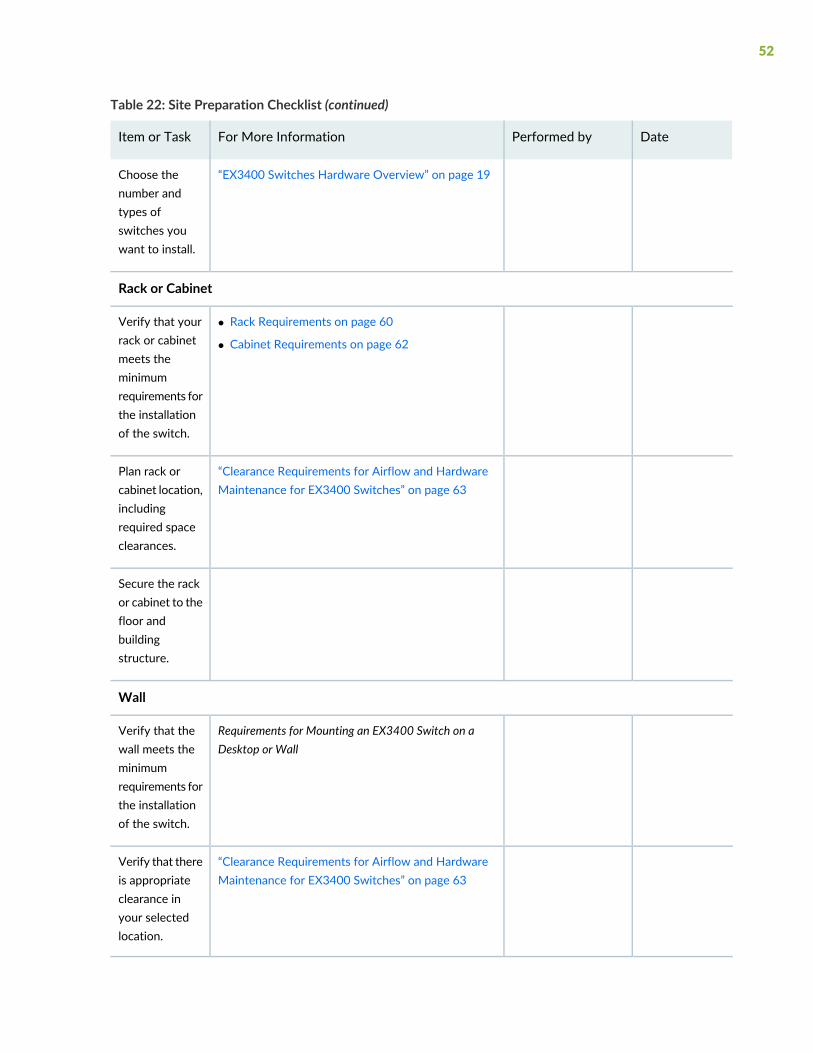
Table 22: Site Preparation Checklist (continued)
DatePerformed byFor More InformationItem or Task
“EX3400 Switches Hardware Overview” on page 19Choose thenumber andtypes ofswitches youwant to install.
Rack or Cabinet
• Rack Requirements on page 60
• Cabinet Requirements on page 62
Verify that yourrack or cabinetmeets theminimumrequirements forthe installationof the switch.
“Clearance Requirements for Airflow and HardwareMaintenance for EX3400 Switches” on page 63
Plan rack orcabinet location,includingrequired spaceclearances.
Secure the rackor cabinet to thefloor andbuildingstructure.
Wall
Requirements for Mounting an EX3400 Switch on aDesktop or Wall
Verify that thewall meets theminimumrequirements forthe installationof the switch.
“Clearance Requirements for Airflow and HardwareMaintenance for EX3400 Switches” on page 63
Verify that thereis appropriateclearance inyour selectedlocation.
52
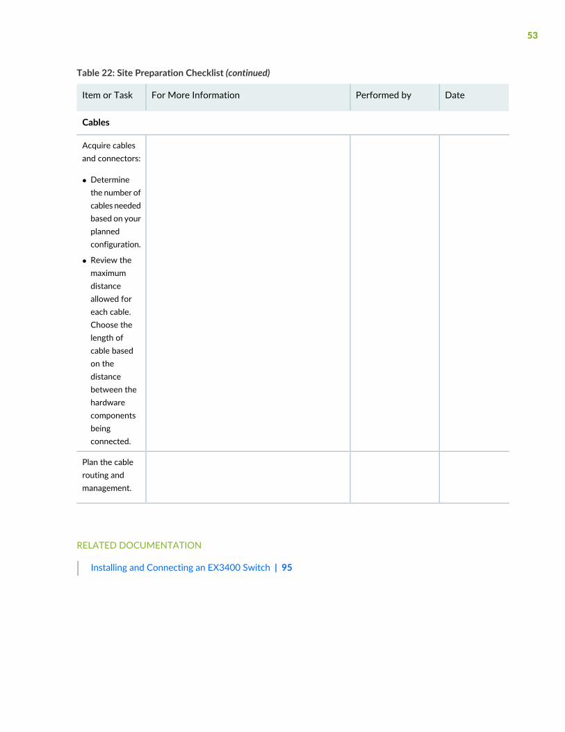
Table 22: Site Preparation Checklist (continued)
DatePerformed byFor More InformationItem or Task
Cables
Acquire cablesand connectors:
• Determinethe number ofcables neededbased on yourplannedconfiguration.
• Review themaximumdistanceallowed foreach cable.Choose thelength ofcable basedon thedistancebetween thehardwarecomponentsbeingconnected.
Plan the cablerouting andmanagement.
RELATED DOCUMENTATION
Installing and Connecting an EX3400 Switch | 95
53

EX3400 Site Guidelines and Requirements
IN THIS SECTION
Environmental Requirements and Specifications for EX Series Switches | 54
General Site Guidelines | 59
Site Electrical Wiring Guidelines | 60
Rack Requirements | 60
Cabinet Requirements | 62
Clearance Requirements for Airflow and Hardware Maintenance for EX3400 Switches | 63
Environmental Requirements and Specifications for EX Series Switches
The switch must be installed in a rack or cabinet housed in a dry, clean, well-ventilated, andtemperature-controlled environment.
Ensure that these environmental guidelines are followed:
• The site must be as dust-free as possible, because dust can clog air intake vents and filters, reducing theefficiency of the switch cooling system.
• Maintain ambient airflow for normal switch operation. If the airflow is blocked or restricted, or if theintake air is too warm, the switch might overheat, leading to the switch temperature monitor shuttingdown the switch to protect the hardware components.
Table 23 on page 55 provides the required environmental conditions for normal switch operation.
54
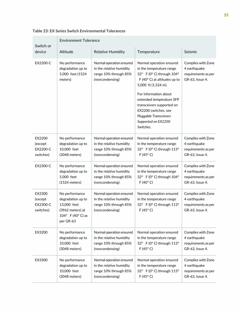
Table 23: EX Series Switch Environmental Tolerances
Environment ToleranceSwitch ordevice SeismicTemperatureRelative HumidityAltitude
Complieswith Zone4 earthquakerequirements as perGR-63, Issue 4.
Normal operation ensuredin the temperature range32° F (0° C) through 104°F (40° C) at altitudes up to5,000 ft (1,524 m).
For information aboutextended temperature SFPtransceivers supported onEX2200 switches, seePluggable TransceiversSupported on EX2200Switches.
Normal operation ensuredin the relative humidityrange 10% through 85%(noncondensing)
No performancedegradation up to5,000 feet (1524meters)
EX2200-C
Complieswith Zone4 earthquakerequirements as perGR-63, Issue 4.
Normal operation ensuredin the temperature range32° F (0° C) through 113°F (45° C)
Normal operation ensuredin the relative humidityrange 10% through 85%(noncondensing)
No performancedegradation up to10,000 feet(3048 meters)
EX2200(exceptEX2200-Cswitches)
Complieswith Zone4 earthquakerequirements as perGR-63, Issue 4.
Normal operation ensuredin the temperature range32° F (0° C) through 104°F (40° C)
Normal operation ensuredin the relative humidityrange 10% through 85%(noncondensing)
No performancedegradation up to5,000 feet(1524 meters)
EX2300-C
Complieswith Zone4 earthquakerequirements as perGR-63, Issue 4.
Normal operation ensuredin the temperature range32° F (0° C) through 113°F (45° C)
Normal operation ensuredin the relative humidityrange 10% through 85%(noncondensing)
No performancedegradation up to13,000 feet(3962 meters) at104° F (40° C) asper GR-63
EX2300(exceptEX2300-Cswitches)
Complieswith Zone4 earthquakerequirements as perGR-63, Issue 4.
Normal operation ensuredin the temperature range32° F (0° C) through 113°F (45° C)
Normal operation ensuredin the relative humidityrange 10% through 85%(noncondensing)
No performancedegradation up to10,000 feet(3048 meters)
EX3200
Complieswith Zone4 earthquakerequirements as perGR-63, Issue 4.
Normal operation ensuredin the temperature range32° F (0° C) through 113°F (45° C)
Normal operation ensuredin the relative humidityrange 10% through 85%(noncondensing)
No performancedegradation up to10,000 feet(3048 meters)
EX3300
55
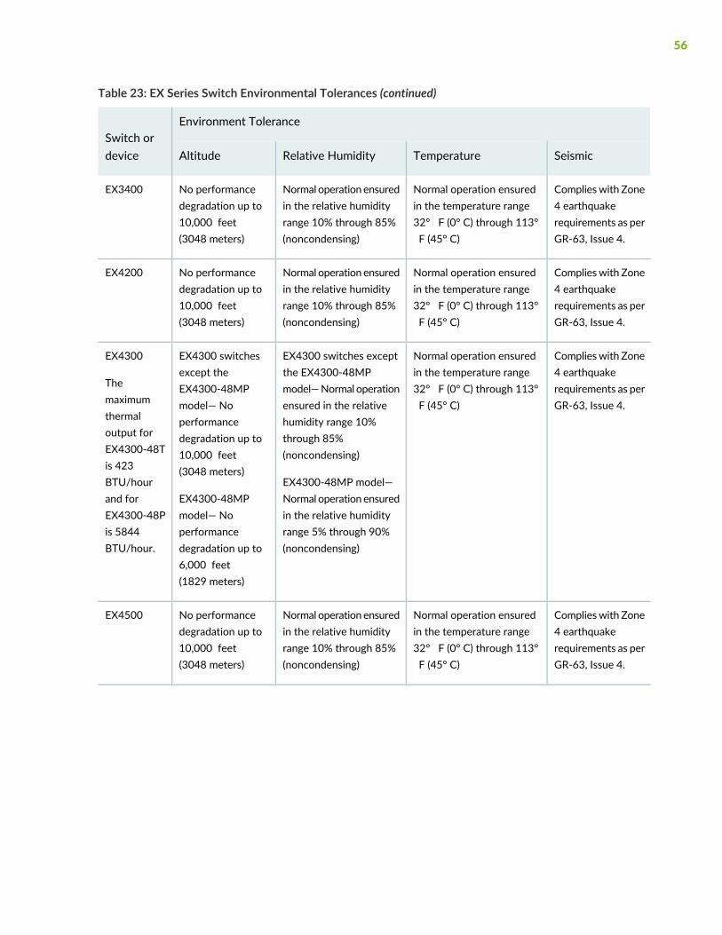
Table 23: EX Series Switch Environmental Tolerances (continued)
Environment ToleranceSwitch ordevice SeismicTemperatureRelative HumidityAltitude
Complieswith Zone4 earthquakerequirements as perGR-63, Issue 4.
Normal operation ensuredin the temperature range32° F (0° C) through 113°F (45° C)
Normal operation ensuredin the relative humidityrange 10% through 85%(noncondensing)
No performancedegradation up to10,000 feet(3048 meters)
EX3400
Complieswith Zone4 earthquakerequirements as perGR-63, Issue 4.
Normal operation ensuredin the temperature range32° F (0° C) through 113°F (45° C)
Normal operation ensuredin the relative humidityrange 10% through 85%(noncondensing)
No performancedegradation up to10,000 feet(3048 meters)
EX4200
Complieswith Zone4 earthquakerequirements as perGR-63, Issue 4.
Normal operation ensuredin the temperature range32° F (0° C) through 113°F (45° C)
EX4300 switches exceptthe EX4300-48MPmodel—Normal operationensured in the relativehumidity range 10%through 85%(noncondensing)
EX4300-48MP model—Normal operation ensuredin the relative humidityrange 5% through 90%(noncondensing)
EX4300 switchesexcept theEX4300-48MPmodel— Noperformancedegradation up to10,000 feet(3048 meters)
EX4300-48MPmodel— Noperformancedegradation up to6,000 feet(1829 meters)
EX4300
Themaximumthermaloutput forEX4300-48Tis 423BTU/hourand forEX4300-48Pis 5844BTU/hour.
Complieswith Zone4 earthquakerequirements as perGR-63, Issue 4.
Normal operation ensuredin the temperature range32° F (0° C) through 113°F (45° C)
Normal operation ensuredin the relative humidityrange 10% through 85%(noncondensing)
No performancedegradation up to10,000 feet(3048 meters)
EX4500
56
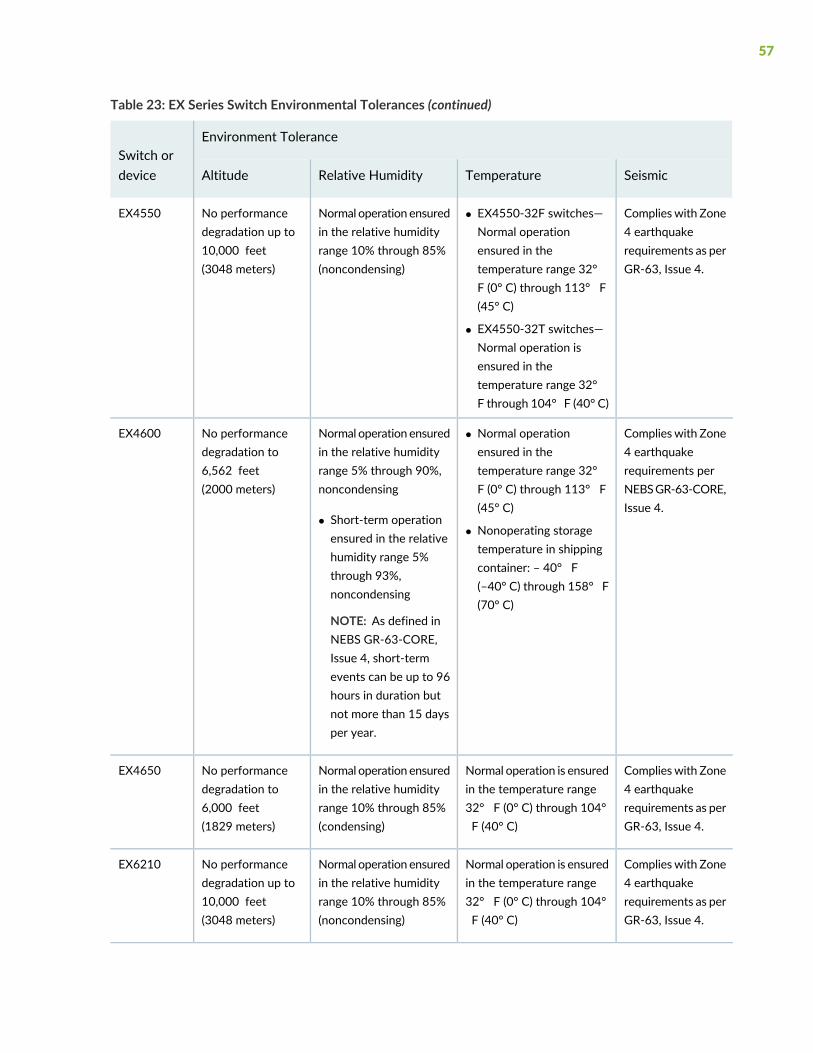
Table 23: EX Series Switch Environmental Tolerances (continued)
Environment ToleranceSwitch ordevice SeismicTemperatureRelative HumidityAltitude
Complieswith Zone4 earthquakerequirements as perGR-63, Issue 4.
• EX4550-32F switches—Normal operationensured in thetemperature range 32°F (0° C) through 113° F(45° C)
• EX4550-32T switches—Normal operation isensured in thetemperature range 32°F through 104° F (40° C)
Normal operation ensuredin the relative humidityrange 10% through 85%(noncondensing)
No performancedegradation up to10,000 feet(3048 meters)
EX4550
Complieswith Zone4 earthquakerequirements perNEBSGR-63-CORE,Issue 4.
• Normal operationensured in thetemperature range 32°F (0° C) through 113° F(45° C)
• Nonoperating storagetemperature in shippingcontainer: – 40° F(–40° C) through 158° F(70° C)
Normal operation ensuredin the relative humidityrange 5% through 90%,noncondensing
• Short-term operationensured in the relativehumidity range 5%through 93%,noncondensing
NOTE: As defined inNEBS GR-63-CORE,Issue 4, short-termevents can be up to 96hours in duration butnot more than 15 daysper year.
No performancedegradation to6,562 feet(2000 meters)
EX4600
Complieswith Zone4 earthquakerequirements as perGR-63, Issue 4.
Normal operation is ensuredin the temperature range32° F (0° C) through 104°F (40° C)
Normal operation ensuredin the relative humidityrange 10% through 85%(condensing)
No performancedegradation to6,000 feet(1829 meters)
EX4650
Complieswith Zone4 earthquakerequirements as perGR-63, Issue 4.
Normal operation is ensuredin the temperature range32° F (0° C) through 104°F (40° C)
Normal operation ensuredin the relative humidityrange 10% through 85%(noncondensing)
No performancedegradation up to10,000 feet(3048 meters)
EX6210
57
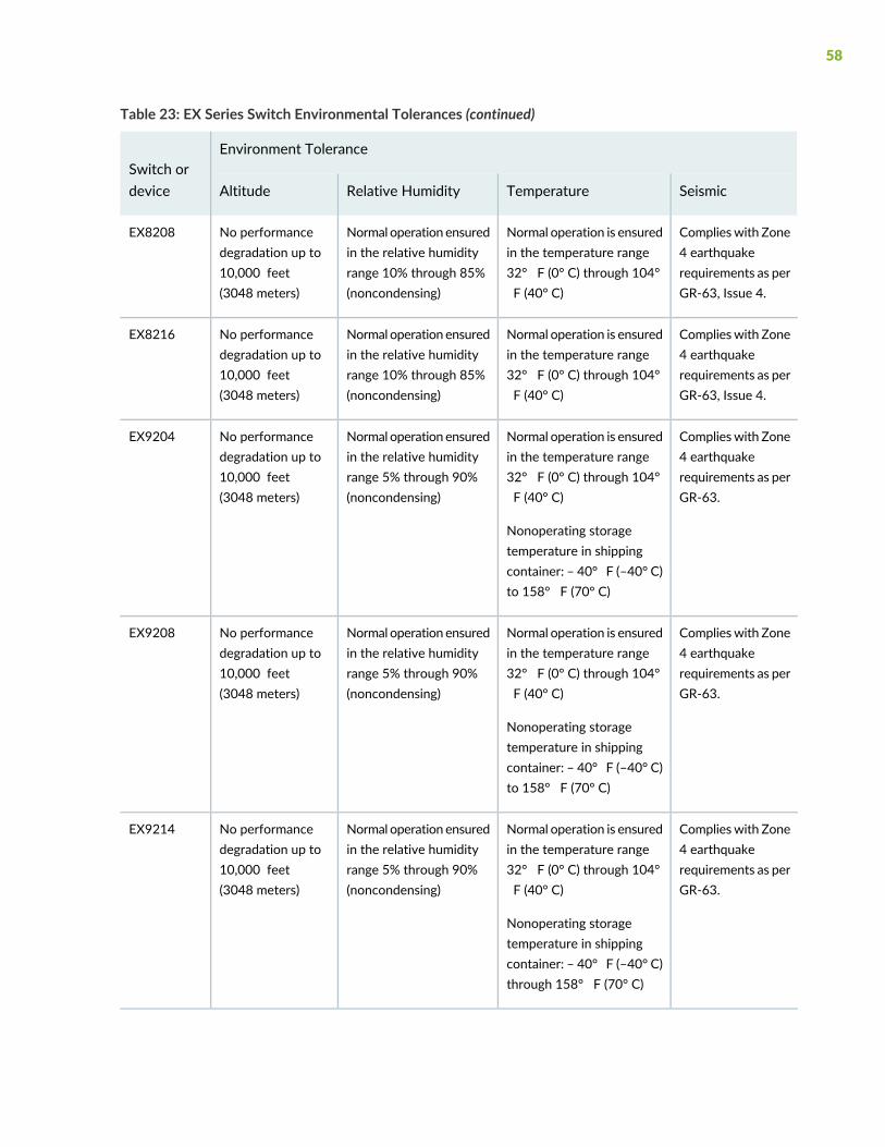
Table 23: EX Series Switch Environmental Tolerances (continued)
Environment ToleranceSwitch ordevice SeismicTemperatureRelative HumidityAltitude
Complieswith Zone4 earthquakerequirements as perGR-63, Issue 4.
Normal operation is ensuredin the temperature range32° F (0° C) through 104°F (40° C)
Normal operation ensuredin the relative humidityrange 10% through 85%(noncondensing)
No performancedegradation up to10,000 feet(3048 meters)
EX8208
Complieswith Zone4 earthquakerequirements as perGR-63, Issue 4.
Normal operation is ensuredin the temperature range32° F (0° C) through 104°F (40° C)
Normal operation ensuredin the relative humidityrange 10% through 85%(noncondensing)
No performancedegradation up to10,000 feet(3048 meters)
EX8216
Complieswith Zone4 earthquakerequirements as perGR-63.
Normal operation is ensuredin the temperature range32° F (0° C) through 104°F (40° C)
Nonoperating storagetemperature in shippingcontainer: – 40° F (–40° C)to 158° F (70° C)
Normal operation ensuredin the relative humidityrange 5% through 90%(noncondensing)
No performancedegradation up to10,000 feet(3048 meters)
EX9204
Complieswith Zone4 earthquakerequirements as perGR-63.
Normal operation is ensuredin the temperature range32° F (0° C) through 104°F (40° C)
Nonoperating storagetemperature in shippingcontainer: – 40° F (–40° C)to 158° F (70° C)
Normal operation ensuredin the relative humidityrange 5% through 90%(noncondensing)
No performancedegradation up to10,000 feet(3048 meters)
EX9208
Complieswith Zone4 earthquakerequirements as perGR-63.
Normal operation is ensuredin the temperature range32° F (0° C) through 104°F (40° C)
Nonoperating storagetemperature in shippingcontainer: – 40° F (–40° C)through 158° F (70° C)
Normal operation ensuredin the relative humidityrange 5% through 90%(noncondensing)
No performancedegradation up to10,000 feet(3048 meters)
EX9214
58
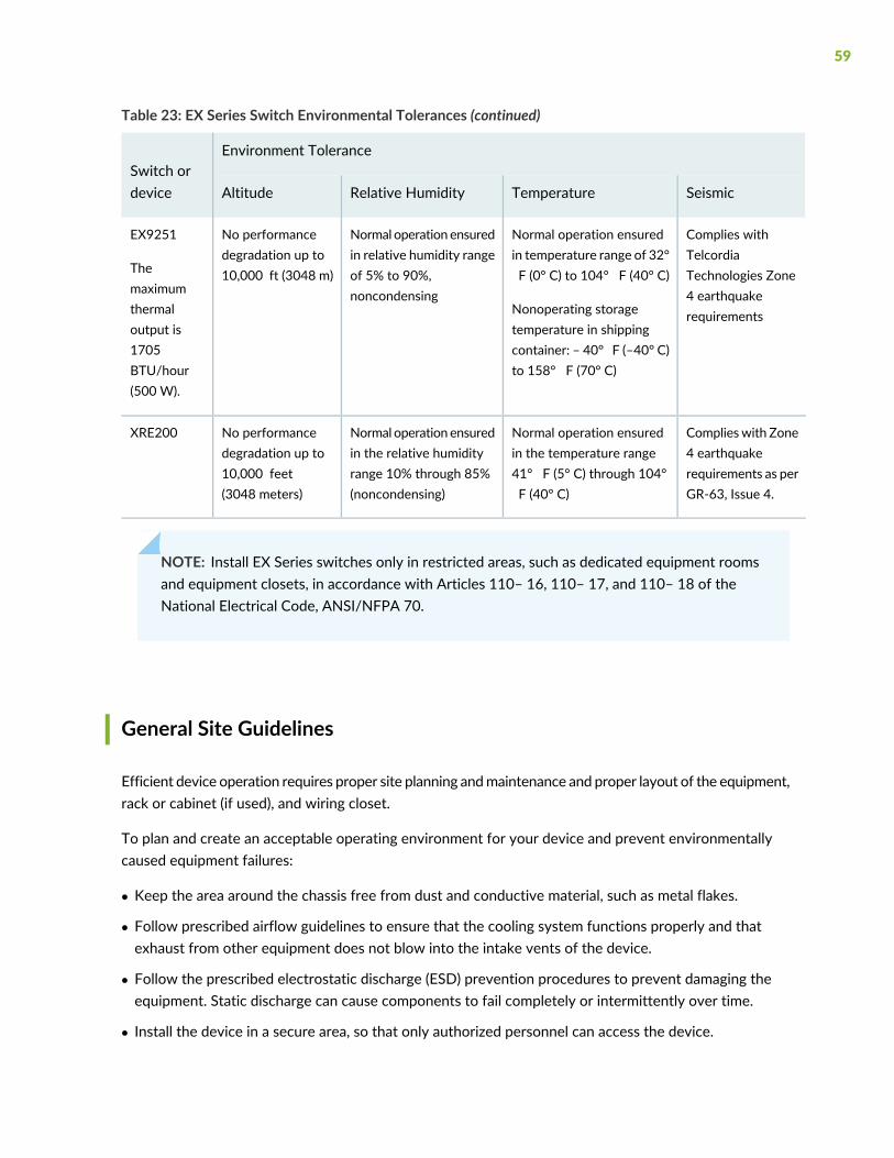
Table 23: EX Series Switch Environmental Tolerances (continued)
Environment ToleranceSwitch ordevice SeismicTemperatureRelative HumidityAltitude
Complies withTelcordiaTechnologies Zone4 earthquakerequirements
Normal operation ensuredin temperature range of 32°F (0° C) to 104° F (40° C)
Nonoperating storagetemperature in shippingcontainer: – 40° F (–40° C)to 158° F (70° C)
Normal operation ensuredin relative humidity rangeof 5% to 90%,noncondensing
No performancedegradation up to10,000 ft (3048 m)
EX9251
Themaximumthermaloutput is1705BTU/hour(500 W).
Complieswith Zone4 earthquakerequirements as perGR-63, Issue 4.
Normal operation ensuredin the temperature range41° F (5° C) through 104°F (40° C)
Normal operation ensuredin the relative humidityrange 10% through 85%(noncondensing)
No performancedegradation up to10,000 feet(3048 meters)
XRE200
NOTE: Install EX Series switches only in restricted areas, such as dedicated equipment roomsand equipment closets, in accordance with Articles 110– 16, 110– 17, and 110– 18 of theNational Electrical Code, ANSI/NFPA 70.
General Site Guidelines
Efficient device operation requires proper site planning andmaintenance and proper layout of the equipment,rack or cabinet (if used), and wiring closet.
To plan and create an acceptable operating environment for your device and prevent environmentallycaused equipment failures:
• Keep the area around the chassis free from dust and conductive material, such as metal flakes.
• Follow prescribed airflow guidelines to ensure that the cooling system functions properly and thatexhaust from other equipment does not blow into the intake vents of the device.
• Follow the prescribed electrostatic discharge (ESD) prevention procedures to prevent damaging theequipment. Static discharge can cause components to fail completely or intermittently over time.
• Install the device in a secure area, so that only authorized personnel can access the device.
59

Site Electrical Wiring Guidelines
Table 24 on page 60 describes the factors you must consider while planning the electrical wiring at yoursite.
WARNING: Youmust provide a properly grounded and shielded environment and useelectrical surge-suppression devices.
Avertissement Vous devez établir un environnement protégé et convenablement misà la terre et utiliser des dispositifs de parasurtension.
Table 24: Site Electrical Wiring Guidelines
GuidelinesSite WiringFactor
If your site experiences any of the following problems, consult experts in electrical surge suppressionand shielding:
• Improperly installed wires cause radio frequency interference (RFI).
• Damage from lightning strikes occurs whenwires exceed recommended distances or pass betweenbuildings.
• Electromagnetic pulses (EMPs) caused by lightning damage unshielded conductors and electronicdevices.
Signalinglimitations
To reduce or eliminate RFI from your site wiring, do the following:
• Use a twisted-pair cable with a good distribution of grounding conductors.
• If you must exceed the recommended distances, use a high-quality twisted-pair cable with oneground conductor for each data signal when applicable.
Radiofrequencyinterference
If your site is susceptible to problems with electromagnetic compatibility (EMC), particularly fromlightning or radio transmitters, seek expert advice.
Some of the problems caused by strong sources of electromagnetic interference (EMI) are:
• Destruction of the signal drivers and receivers in the device
• Electrical hazards as a result of power surges conducted over the lines into the equipment
Electromagneticcompatibility
Rack Requirements
You can mount the device on two-post racks or four-post racks.
60
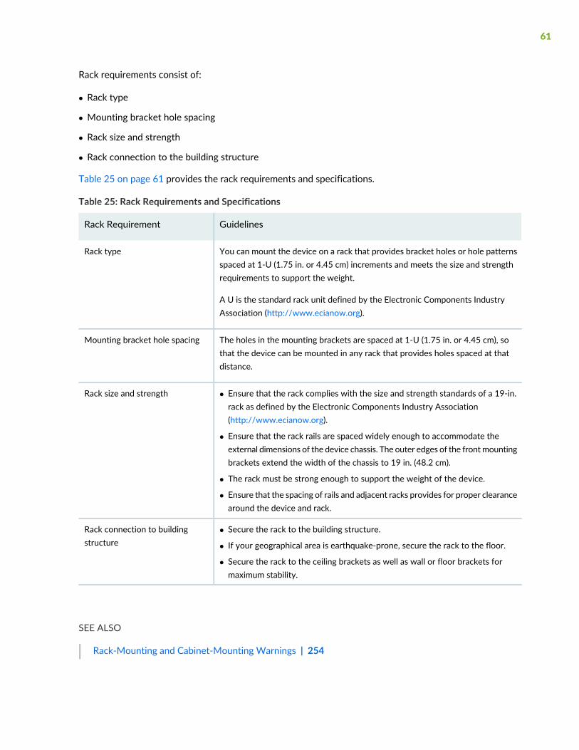
Rack requirements consist of:
• Rack type
• Mounting bracket hole spacing
• Rack size and strength
• Rack connection to the building structure
Table 25 on page 61 provides the rack requirements and specifications.
Table 25: Rack Requirements and Specifications
GuidelinesRack Requirement
You can mount the device on a rack that provides bracket holes or hole patternsspaced at 1-U (1.75 in. or 4.45 cm) increments and meets the size and strengthrequirements to support the weight.
A U is the standard rack unit defined by the Electronic Components IndustryAssociation (http://www.ecianow.org).
Rack type
The holes in the mounting brackets are spaced at 1-U (1.75 in. or 4.45 cm), sothat the device can be mounted in any rack that provides holes spaced at thatdistance.
Mounting bracket hole spacing
• Ensure that the rack complies with the size and strength standards of a 19-in.rack as defined by the Electronic Components Industry Association(http://www.ecianow.org).
• Ensure that the rack rails are spaced widely enough to accommodate theexternal dimensions of the device chassis. The outer edges of the frontmountingbrackets extend the width of the chassis to 19 in. (48.2 cm).
• The rack must be strong enough to support the weight of the device.
• Ensure that the spacing of rails and adjacent racks provides for proper clearancearound the device and rack.
Rack size and strength
• Secure the rack to the building structure.
• If your geographical area is earthquake-prone, secure the rack to the floor.
• Secure the rack to the ceiling brackets as well as wall or floor brackets formaximum stability.
Rack connection to buildingstructure
SEE ALSO
Rack-Mounting and Cabinet-Mounting Warnings | 254
61
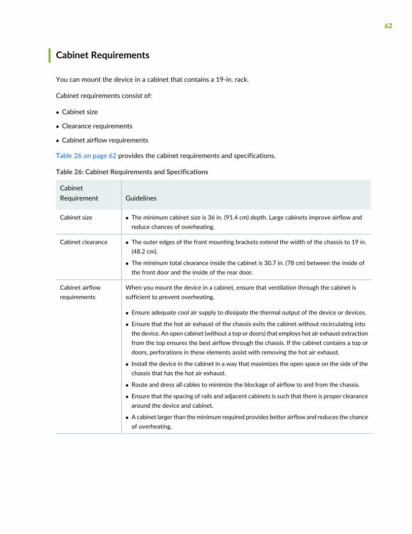
Cabinet Requirements
You can mount the device in a cabinet that contains a 19-in. rack.
Cabinet requirements consist of:
• Cabinet size
• Clearance requirements
• Cabinet airflow requirements
Table 26 on page 62 provides the cabinet requirements and specifications.
Table 26: Cabinet Requirements and Specifications
GuidelinesCabinetRequirement
• The minimum cabinet size is 36 in. (91.4 cm) depth. Large cabinets improve airflow andreduce chances of overheating.
Cabinet size
• The outer edges of the front mounting brackets extend the width of the chassis to 19 in.(48.2 cm).
• The minimum total clearance inside the cabinet is 30.7 in. (78 cm) between the inside ofthe front door and the inside of the rear door.
Cabinet clearance
When you mount the device in a cabinet, ensure that ventilation through the cabinet issufficient to prevent overheating.
• Ensure adequate cool air supply to dissipate the thermal output of the device or devices.
• Ensure that the hot air exhaust of the chassis exits the cabinet without recirculating intothe device. An open cabinet (without a top or doors) that employs hot air exhaust extractionfrom the top ensures the best airflow through the chassis. If the cabinet contains a top ordoors, perforations in these elements assist with removing the hot air exhaust.
• Install the device in the cabinet in a way that maximizes the open space on the side of thechassis that has the hot air exhaust.
• Route and dress all cables to minimize the blockage of airflow to and from the chassis.
• Ensure that the spacing of rails and adjacent cabinets is such that there is proper clearancearound the device and cabinet.
• A cabinet larger than theminimum required provides better airflow and reduces the chanceof overheating.
Cabinet airflowrequirements
62
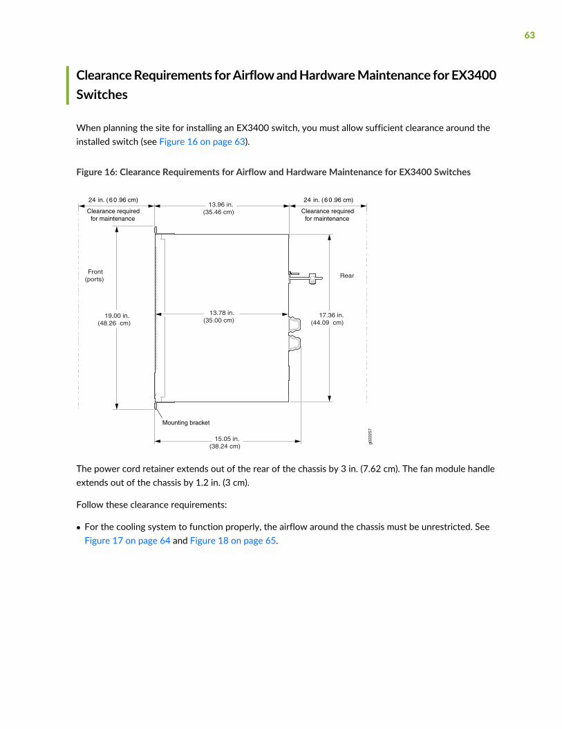
ClearanceRequirements forAirflowandHardwareMaintenance for EX3400Switches
When planning the site for installing an EX3400 switch, you must allow sufficient clearance around theinstalled switch (see Figure 16 on page 63).
Figure 16: Clearance Requirements for Airflow and Hardware Maintenance for EX3400 Switches
g022
257
13.96 in.(35.46 cm)
17.36 in.(44.09 cm)
19.00 in.(48.26 cm)
Clearance requiredfor maintenance
24 in. ( 6 0 .96 cm)
Front(ports)
Rear
Clearance requiredfor maintenance
24 in. ( 6 0 .96 cm)
Mounting bracket
13.78 in.(35.00 cm)
15.05 in.(38.24 cm)
The power cord retainer extends out of the rear of the chassis by 3 in. (7.62 cm). The fan module handleextends out of the chassis by 1.2 in. (3 cm).
Follow these clearance requirements:
• For the cooling system to function properly, the airflow around the chassis must be unrestricted. SeeFigure 17 on page 64 and Figure 18 on page 65.
63
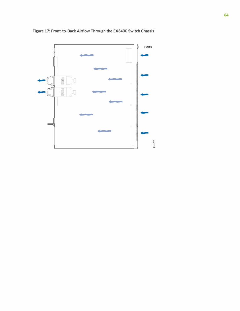
Figure 17: Front-to-Back Airflow Through the EX3400 Switch Chassis
64
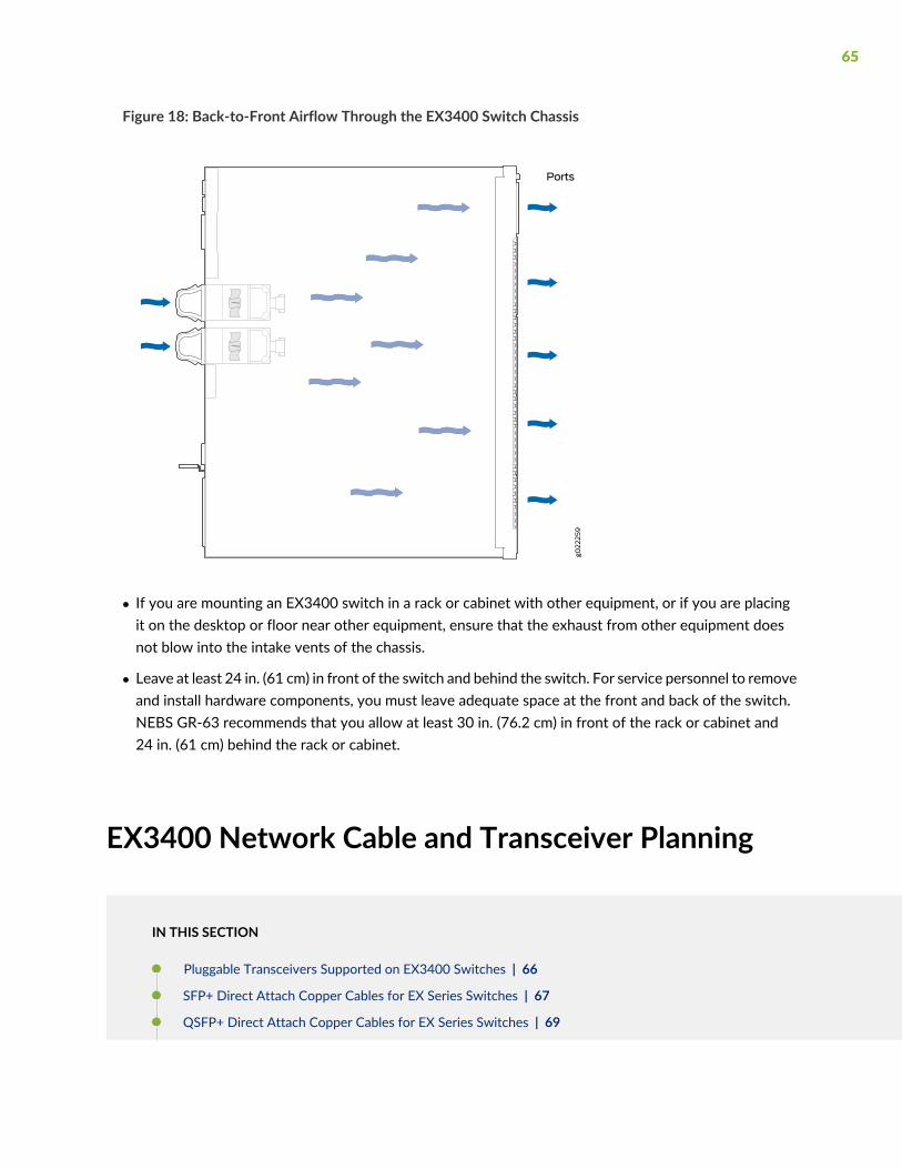
Figure 18: Back-to-Front Airflow Through the EX3400 Switch Chassis
• If you are mounting an EX3400 switch in a rack or cabinet with other equipment, or if you are placingit on the desktop or floor near other equipment, ensure that the exhaust from other equipment doesnot blow into the intake vents of the chassis.
• Leave at least 24 in. (61 cm) in front of the switch and behind the switch. For service personnel to removeand install hardware components, you must leave adequate space at the front and back of the switch.NEBS GR-63 recommends that you allow at least 30 in. (76.2 cm) in front of the rack or cabinet and24 in. (61 cm) behind the rack or cabinet.
EX3400 Network Cable and Transceiver Planning
IN THIS SECTION
Pluggable Transceivers Supported on EX3400 Switches | 66
SFP+ Direct Attach Copper Cables for EX Series Switches | 67
QSFP+ Direct Attach Copper Cables for EX Series Switches | 69
65
Understanding EX Series Switches Fiber-Optic Cable Signal Loss, Attenuation, and Dispersion | 70
Calculating the Fiber-Optic Cable Power Budget for EX Series Devices | 72
Calculating the Fiber-Optic Cable Power Margin for EX Series Devices | 72
Pluggable Transceivers Supported on EX3400 Switches
Uplink ports on EX3400 switches support SFP, SFP+, and QSFP+ transceivers. You can find the list oftransceivers supported on EX3400 switches and information about those transceivers at the HardwareCompatibility Tool page for EX3400.
NOTE: We recommend that you use only optical transceivers and optical connectors purchasedfrom Juniper Networks with your Juniper Networks device.
CAUTION: If you face a problem running a Juniper Networks device that uses athird-party optic or cable, the Juniper Networks Technical Assistance Center (JTAC)can help you diagnose the source of the problem. Your JTACengineermight recommendthat you check the third-party optic or cable and potentially replace it with an equivalentJuniper Networks optic or cable that is qualified for the device.
The Gigabit Ethernet SFP, SFP+, and QSFP+ transceivers installed in EX3400 switches support digitaloptical monitoring (DOM): You can view the diagnostic details for these transceivers by issuing theoperational mode CLI command show interfaces diagnostics optics.
NOTE: The transceivers support DOM even if they are installed in uplink ports configured asVirtual Chassis ports.
SEE ALSO
Front Panel of an EX3400 Switch | 28
Install a Transceiver | 126
66
Remove a Transceiver | 207
SFP+ Direct Attach Copper Cables for EX Series Switches
IN THIS SECTION
Cable Specifications | 67
List of DAC Cables Supported on EX Series Switches | 68
Standards Supported by These Cables | 68
Small form-factor pluggable plus transceiver (SFP+) direct attach copper (DAC) cables, also known asTwinax cables, are suitable for in-rack connections between servers and switches. They are suitable forshort distances, making them ideal for highly cost-effective networking connectivity within a rack andbetween adjacent racks.
NOTE: We recommend that you use only SFP+ DAC cables purchased from Juniper Networkswith your Juniper Networks device.
CAUTION: If you face a problem running a Juniper Networks device that uses athird-party optic or cable, the Juniper Networks Technical Assistance Center (JTAC)can help you diagnose the source of the problem. Your JTACengineermight recommendthat you check the third-party optic or cable and potentially replace it with an equivalentJuniper Networks optic or cable that is qualified for the device.
Cable Specifications
EX Series switches support SFP+ passive DAC cables. The passive Twinax cable is a straight cable withno active electronic components. EX Series switches support 1 m, 3 m, 5 m, and 7 m long SFP+ passiveDAC cables. See Figure 19 on page 68.
67

Figure 19: SFP+ Direct Attach Copper Cables for EX Series Switches
The cables are hot-removable and hot-insertable: You can remove and replace them without poweringoff the switch or disrupting switch functions. A cable comprises a low-voltage cable assembly that connectsdirectly into two 10-Gigabit Ethernet ports, one at each end of the cable. The cables use high-performanceintegrated duplex serial data links for bidirectional communication and are designed for data rates of upto 10 Gbps.
List of DAC Cables Supported on EX Series Switches
For the list of DAC cables supported on EX Series switches and the specifications of these cables, see:
• EX2300—Hardware Compatibility Tool page for EX2300
• EX3200—Hardware Compatibility Tool page for EX3200
• EX3300—Hardware Compatibility Tool page for EX3300
• EX3400—Hardware Compatibility Tool page for EX3400
• EX4200—Hardware Compatibility Tool page for EX4200
• EX4300—Hardware Compatibility Tool page for EX4300
• EX4500—Hardware Compatibility Tool page for EX4500
• EX4550—Hardware Compatibility Tool page for EX4550
• EX4600—Hardware Compatibility Tool page for EX4600
• EX8208—Hardware Compatibility Tool page for EX8208
• EX8216—Hardware Compatibility Tool page for EX8216
• EX9251—Hardware Compatibility Tool page for EX9251
• EX9253—Hardware Compatibility Tool page for EX9253
Standards Supported by These Cables
The cables comply with the following standards:
• SFP mechanical standard SFF-843— see ftp://ftp.seagate.com/sff/SFF-8431.PDF.
• Electrical interface standard SFF-8432— see ftp://ftp.seagate.com/sff/SFF-8432.PDF.
68
• SFP+ Multi-Source Alliance (MSA) standards
QSFP+ Direct Attach Copper Cables for EX Series Switches
IN THIS SECTION
Cable Specifications | 69
DAC Cables Supported on EX3400, EX4300, EX4550, EX4600, EX9251, and EX9253 Switches | 70
Quad small form-factor pluggable plus (QSFP+) direct attach copper (DAC) cables are suitable for in-rackconnections betweenQSFP+ ports on EX3400, EX4300, EX4550, EX4600, EX9251, and EX9253 switches.They are suitable for short distances, making them ideal for highly cost-effective networking connectivitywithin a rack and between adjacent racks.
NOTE: We recommend that you use only QSFP+DAC cables purchased from Juniper Networkswith your Juniper Networks device.
CAUTION: If you face a problem running a Juniper Networks device that uses athird-party optic or cable, the Juniper Networks Technical Assistance Center (JTAC)can help you diagnose the source of the problem. Your JTACengineermight recommendthat you check the third-party optic or cable and potentially replace it with an equivalentJuniper Networks optic or cable that is qualified for the device.
Cable Specifications
QSFP+ passive DAC cables are hot-removable and hot-insertable. A cable consists of a cable assemblythat connects directly into two QSFP+ modules, one at each end of the cable. The cables use integratedduplex serial data links for bidirectional communication and are designed for data rates up to 40 Gbps.Passive DAC cables have no signal amplification built into the cable assembly. See Figure 20 on page 70.
69

Figure 20: QSFP+ Direct Attach Copper Cables
DAC Cables Supported on EX3400, EX4300, EX4550, EX4600, EX9251, and EX9253 Switches
For the list of DAC cables supported on EX3400, EX4300, EX4550, EX4600, EX9251, and EX9253 switchesand the specifications of these cables, see:
• EX3400—Hardware Compatibility Tool page for EX3400
• EX4300—Hardware Compatibility Tool page for EX4300
• EX4550—Hardware Compatibility Tool page for EX4550
• EX4600—Hardware Compatibility Tool page for EX4600
• EX9251—Hardware Compatibility Tool page for EX9251
• EX9253—Hardware Compatibility Tool page for EX9253
Understanding EX Series Switches Fiber-Optic Cable Signal Loss,Attenuation, and Dispersion
IN THIS SECTION
Signal Loss in Multimode and Single-Mode Fiber-Optic Cable | 71
Attenuation and Dispersion in Fiber-Optic Cable | 71
70

To determine the power budget and power margin needed for fiber-optic connections, you need tounderstand how signal loss, attenuation, and dispersion affect transmission. EX Series switches use varioustypes of network cable, including multimode and single-mode fiber-optic cable.
Signal Loss in Multimode and Single-Mode Fiber-Optic Cable
Multimode fiber is large enough in diameter to allow rays of light to reflect internally (bounce off the wallsof the fiber). Interfaces with multimode optics typically use LEDs as light sources. However, LEDs are notcoherent light sources. They spray varying wavelengths of light into the multimode fiber, which reflectsthe light at different angles. Light rays travel in jagged lines through a multimode fiber, causing signaldispersion. When light traveling in the fiber core radiates into the fiber cladding (layers of lower refractiveindex material in close contact with a core material of higher refractive index), higher-order mode loss(HOL) occurs. Together, these factors reduce the transmission distance of multimode fiber compared tothat of single-mode fiber.
Single-mode fiber is so small in diameter that rays of light reflect internally through one layer only. Interfaceswith single-mode optics use lasers as light sources. Lasers generate a single wavelength of light, whichtravels in a straight line through the single-mode fiber. Compared to multimode fiber, single-mode fiberhas a higher bandwidth and can carry signals for longer distances. It is consequently more expensive.
Exceeding themaximum transmission distances can result in significant signal loss, which causes unreliabletransmission.
Attenuation and Dispersion in Fiber-Optic Cable
An optical data link functions correctly provided that modulated light reaching the receiver has enoughpower to be demodulated correctly. Attenuation is the reduction in strength of the light signal duringtransmission. Passive media components such as cables, cable splices, and connectors cause attenuation.Although attenuation is significantly lower for optical fiber than for other media, it still occurs in bothmultimode and single-mode transmission. An efficient optical data link must transmit enough light toovercome attenuation.
Dispersion is the spreading of the signal over time. The following two types of dispersion can affect signaltransmission through an optical data link:
• Chromatic dispersion, which is the spreading of the signal over time caused by the different speeds oflight rays.
• Modal dispersion, which is the spreading of the signal over time caused by the different propagationmodes in the fiber.
For multimode transmission, modal dispersion, rather than chromatic dispersion or attenuation, usuallylimits the maximum bit rate and link length. For single-mode transmission, modal dispersion is not a factor.However, at higher bit rates and over longer distances, chromatic dispersion limits themaximum link length.
71

An efficient optical data link must have enough light to exceed the minimum power that the receiverrequires to operate within its specifications. In addition, the total dispersion must be within the limitsspecified for the type of link in Telcordia Technologies document GR-253-CORE (Section 4.3) andInternational Telecommunications Union (ITU) document G.957.
When chromatic dispersion is at the maximum allowed, its effect can be considered as a power penalty inthe power budget. The optical power budget must allow for the sum of component attenuation, powerpenalties (including those from dispersion), and a safety margin for unexpected losses.
Calculating the Fiber-Optic Cable Power Budget for EX Series Devices
To ensure that fiber-optic connections have sufficient power for correct operation, calculate the link'spower budget when planning fiber-optic cable layout and distances to ensure that fiber-optic connectionshave sufficient power for correct operation. The power budget is the maximum amount of power the linkcan transmit. When you calculate the power budget, you use a worst-case analysis to provide a margin oferror, even though all the parts of an actual system do not operate at the worst-case levels.
To calculate the worst-case estimate for fiber-optic cable power budget (PB) for the link:
1. Determine values for the link's minimum transmitter power (PT) and minimum receiver sensitivity (P
R).
For example, here, (PT) and (P
R) are measured in decibels, and decibels are referred to one milliwatt
(dBm).
PT= – 15 dBm
PR= – 28 dBm
NOTE: See the specifications for your transmitter and receiver to find theminimum transmitterpower and minimum receiver sensitivity.
2. Calculate the power budget (PB) by subtracting (P
R) from (P
T):
– 15 dBm – (–28 dBm) = 13 dBm
Calculating the Fiber-Optic Cable Power Margin for EX Series Devices
Calculate the link's power margin when planning fiber-optic cable layout and distances to ensure thatfiber-optic connections have sufficient signal power to overcome system losses and still satisfy theminimum
72

input requirements of the receiver for the required performance level. The powermargin (PM) is the amount
of power available after attenuation or link loss (LL) has been subtracted from the power budget (PB).
When you calculate the power margin, you use a worst-case analysis to provide a margin of error, eventhough all the parts of an actual system do not operate at worst-case levels. A power margin (P
M) greater
than zero indicates that the power budget is sufficient to operate the receiver and that it does not exceedthe maximum receiver input power. This means the link will work. A (P
M) that is zero or negative indicates
insufficient power to operate the receiver. See the specification for your receiver to find the maximumreceiver input power.
Before calculating the power margin:
• Calculate the power budget (see “Calculating the Fiber-Optic Cable Power Budget for EX Series Devices”on page 72).
To calculate the worst-case estimate for the power margin (PM) for the link:
1. Determine the maximum value for link loss (LL) by adding estimated values for applicable link-lossfactors—for example, use the sample values for various factors as provided in Table 27 on page 73(here, the link is 2 km long and multimode, and the (P
B) is 13 dBm):
Table 27: Estimated Values for Factors Causing Link Loss
Sample (LL) Calculation ValuesEstimated Link-Loss ValueLink-Loss Factor
• 0.5 dBm
• 0 dBm• Multimode—0.5 dBm
• Single mode—None
Higher-order mode losses (HOL)
• 0 dBm
• 0 dBm• Multimode—None, if product ofbandwidth and distance is less than500 MHz/km
• Single mode—None
Modal and chromatic dispersion
This example assumes 5 connectors.Loss for 5 connectors:
(5) * (0.5 dBm) = 2.5 dBm
0.5 dBmConnector
This example assumes 2 splices. Loss fortwo splices:
(2) * (0.5 dBm) = 1 dBm
0.5 dBmSplice
This example assumes the link is 2 kmlong. Fiber attenuation for 2 km:
• (2 km) * (1.0 dBm/km) = 2 dBm
• (2 km) * (0.5 dBm/km) = 1 dBm
• Multimode—1 dBm/km
• Single mode—0.5 dBm/km
Fiber attenuation
73

Table 27: Estimated Values for Factors Causing Link Loss (continued)
Sample (LL) Calculation ValuesEstimated Link-Loss ValueLink-Loss Factor
1 dBm1 dBmClock Recovery Module (CRM)
NOTE: For information about the actual amount of signal loss caused by equipment andother factors, see your vendor documentation for that equipment.
2. Calculate the (PM) by subtracting (LL) from (P
B):
PB– LL = P
M
(13 dBm) – (0.5 dBm [HOL]) – ((5) * (0.5 dBm)) – ((2) * (0.5 dBm)) – ((2 km) * (1.0 dBm/km)) – (1 dB[CRM]) = P
M
13 dBm – 0.5 dBm – 2.5 dBm – 1 dBm – 2 dBm – 1 dBm = PM
PM= 6 dBm
The calculated power margin is greater than zero, indicating that the link has sufficient power fortransmission. Also, the power margin value does not exceed the maximum receiver input power. Referto the specification for your receiver to find the maximum receiver input power.
EX3400ManagementCable Specifications andPinouts
IN THIS SECTION
Management Cable Specifications | 75
Console Port Connector Pinout Information | 75
RJ-45 Management Port Connector Pinout Information | 76
USB Port Specifications for an EX Series Switch | 77
RJ-45 Port, SFP Port, SFP+ Port, QSFP+ Port, and QSFP28 Port Connector Pinout Information | 77
SFP+ Uplink Port Connector Pinout Information for an EX3400 Switch | 82
QSFP+ Uplink Port Connector Pinout Information for an EX3400 Switch | 83
RJ-45 to DB-9 Serial Port Adapter Pinout Information | 85
74
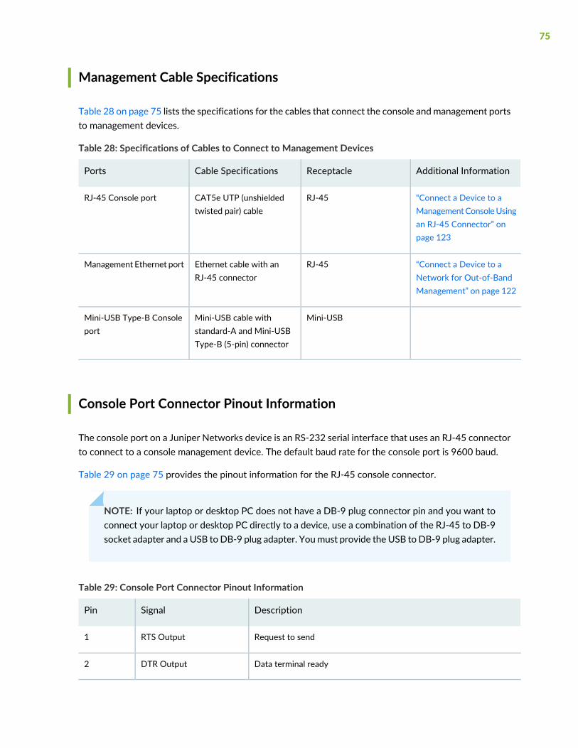
Management Cable Specifications
Table 28 on page 75 lists the specifications for the cables that connect the console and management portsto management devices.
Table 28: Specifications of Cables to Connect to Management Devices
Additional InformationReceptacleCable SpecificationsPorts
“Connect a Device to aManagementConsoleUsingan RJ-45 Connector” onpage 123
RJ-45CAT5e UTP (unshieldedtwisted pair) cable
RJ-45 Console port
“Connect a Device to aNetwork for Out-of-BandManagement” on page 122
RJ-45Ethernet cable with anRJ-45 connector
Management Ethernet port
Mini-USBMini-USB cable withstandard-A and Mini-USBType-B (5-pin) connector
Mini-USB Type-B Consoleport
Console Port Connector Pinout Information
The console port on a Juniper Networks device is an RS-232 serial interface that uses an RJ-45 connectorto connect to a console management device. The default baud rate for the console port is 9600 baud.
Table 29 on page 75 provides the pinout information for the RJ-45 console connector.
NOTE: If your laptop or desktop PC does not have a DB-9 plug connector pin and you want toconnect your laptop or desktop PC directly to a device, use a combination of the RJ-45 to DB-9socket adapter and a USB toDB-9 plug adapter. Youmust provide the USB toDB-9 plug adapter.
Table 29: Console Port Connector Pinout Information
DescriptionSignalPin
Request to sendRTS Output1
Data terminal readyDTR Output2
75
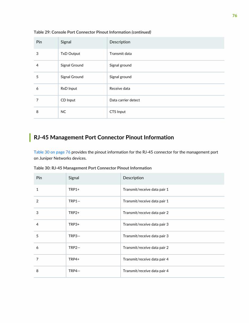
Table 29: Console Port Connector Pinout Information (continued)
DescriptionSignalPin
Transmit dataTxD Output3
Signal groundSignal Ground4
Signal groundSignal Ground5
Receive dataRxD Input6
Data carrier detectCD Input7
CTS InputNC8
RJ-45 Management Port Connector Pinout Information
Table 30 on page 76 provides the pinout information for the RJ-45 connector for the management porton Juniper Networks devices.
Table 30: RJ-45 Management Port Connector Pinout Information
DescriptionSignalPin
Transmit/receive data pair 1TRP1+1
Transmit/receive data pair 1TRP1—2
Transmit/receive data pair 2TRP2+3
Transmit/receive data pair 3TRP3+4
Transmit/receive data pair 3TRP3—5
Transmit/receive data pair 2TRP2—6
Transmit/receive data pair 4TRP4+7
Transmit/receive data pair 4TRP4—8
76
USB Port Specifications for an EX Series Switch
The following Juniper Networks USB flash drives have been tested and are officially supported for theUSB port on all EX Series switches:
• RE-USB-1G-S
• RE-USB-2G-S
• RE-USB-4G-S
CAUTION: Any USB memory product not listed as supported for EX Series switcheshas not been tested by Juniper Networks. The use of any unsupported USB memoryproduct could expose your EX Series switch to unpredictable behavior. JuniperNetworks Technical Assistance Center (JTAC) can provide only limited support forissues related to unsupported hardware. We strongly recommend that you use onlysupported USB flash drives.
All USB flash drives used on EX Series switches must have the following features:
• USB 2.0 or later.
• Formatted with a FAT or MS-DOS file system.
• If the switch is running Junos OS Release 9.5 or earlier, the formatting method must use a primary bootrecord. Microsoft Windows formatting, by default, does not use a primary boot record. See thedocumentation for your USB flash drive for information about how your USB flash drive is formatted.
RJ-45 Port, SFP Port, SFP+ Port, QSFP+ Port, andQSFP28 Port ConnectorPinout Information
The tables in this topic describe the connector pinout information for the RJ-45, QSFP+, QSFP28, SFP+,and SFP ports.
• Table 31 on page 78—10/100/1000BASE-T Ethernet network port connector pinout information
• Table 32 on page 78—SFP network port connector pinout information
• Table 33 on page 79—SFP+ network port connector pinout information
• Table 34 on page 80—QSFP+ and QSFP28 network module ports connector pinout information
77
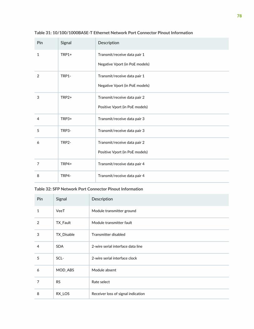
Table 31: 10/100/1000BASE-T Ethernet Network Port Connector Pinout Information
DescriptionSignalPin
Transmit/receive data pair 1
Negative Vport (in PoE models)
TRP1+1
Transmit/receive data pair 1
Negative Vport (in PoE models)
TRP1-2
Transmit/receive data pair 2
Positive Vport (in PoE models)
TRP2+3
Transmit/receive data pair 3TRP3+4
Transmit/receive data pair 3TRP3-5
Transmit/receive data pair 2
Positive Vport (in PoE models)
TRP2-6
Transmit/receive data pair 4TRP4+7
Transmit/receive data pair 4TRP4-8
Table 32: SFP Network Port Connector Pinout Information
DescriptionSignalPin
Module transmitter groundVeeT1
Module transmitter faultTX_Fault2
Transmitter disabledTX_Disable3
2-wire serial interface data lineSDA4
2-wire serial interface clockSCL-5
Module absentMOD_ABS6
Rate selectRS7
Receiver loss of signal indicationRX_LOS8
78
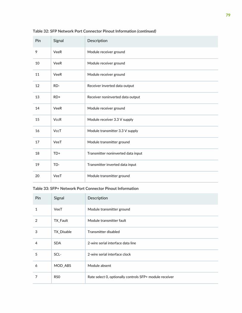
Table 32: SFP Network Port Connector Pinout Information (continued)
DescriptionSignalPin
Module receiver groundVeeR9
Module receiver groundVeeR10
Module receiver groundVeeR11
Receiver inverted data outputRD-12
Receiver noninverted data outputRD+13
Module receiver groundVeeR14
Module receiver 3.3 V supplyVccR15
Module transmitter 3.3 V supplyVccT16
Module transmitter groundVeeT17
Transmitter noninverted data inputTD+18
Transmitter inverted data inputTD-19
Module transmitter groundVeeT20
Table 33: SFP+ Network Port Connector Pinout Information
DescriptionSignalPin
Module transmitter groundVeeT1
Module transmitter faultTX_Fault2
Transmitter disabledTX_Disable3
2-wire serial interface data lineSDA4
2-wire serial interface clockSCL-5
Module absentMOD_ABS6
Rate select 0, optionally controls SFP+ module receiverRS07
79
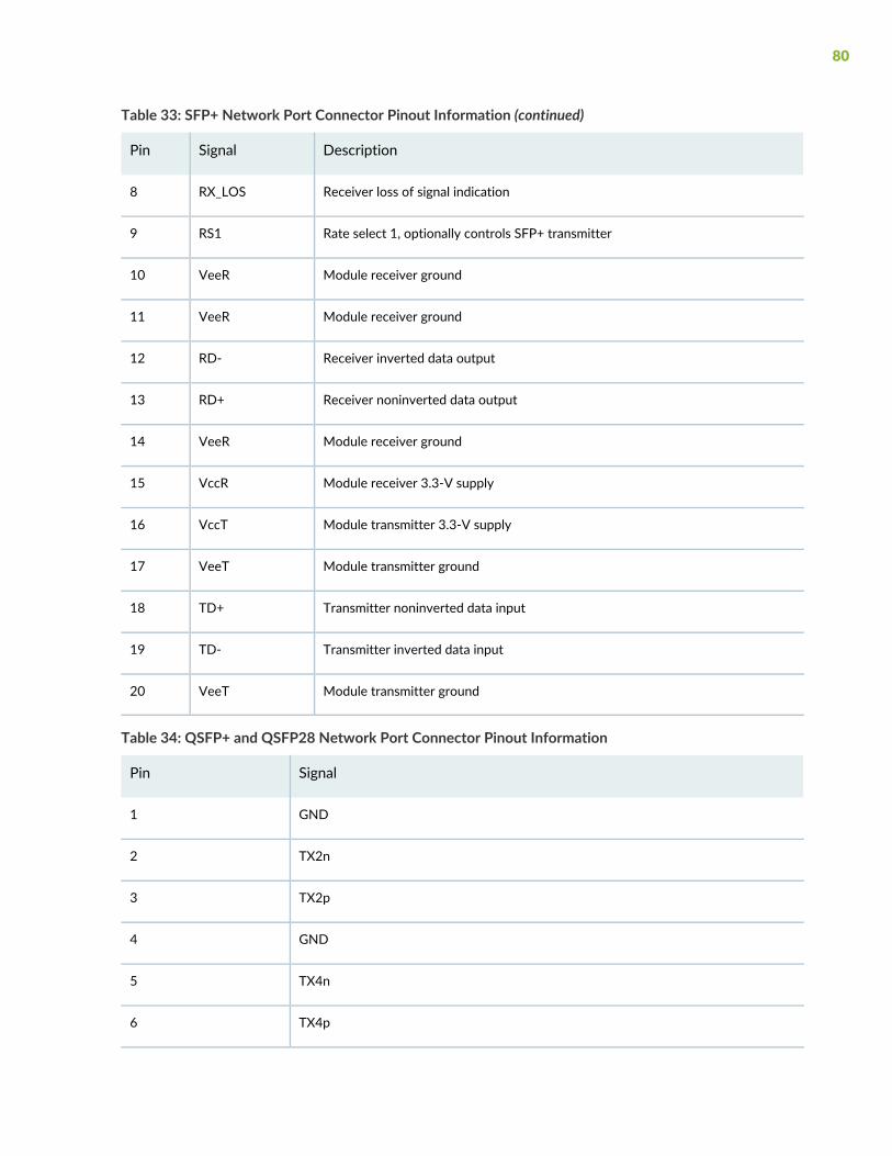
Table 33: SFP+ Network Port Connector Pinout Information (continued)
DescriptionSignalPin
Receiver loss of signal indicationRX_LOS8
Rate select 1, optionally controls SFP+ transmitterRS19
Module receiver groundVeeR10
Module receiver groundVeeR11
Receiver inverted data outputRD-12
Receiver noninverted data outputRD+13
Module receiver groundVeeR14
Module receiver 3.3-V supplyVccR15
Module transmitter 3.3-V supplyVccT16
Module transmitter groundVeeT17
Transmitter noninverted data inputTD+18
Transmitter inverted data inputTD-19
Module transmitter groundVeeT20
Table 34: QSFP+ and QSFP28 Network Port Connector Pinout Information
SignalPin
GND1
TX2n2
TX2p3
GND4
TX4n5
TX4p6
80
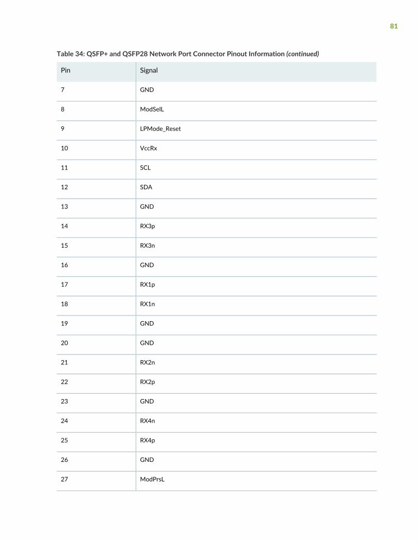
Table 34: QSFP+ and QSFP28 Network Port Connector Pinout Information (continued)
SignalPin
GND7
ModSelL8
LPMode_Reset9
VccRx10
SCL11
SDA12
GND13
RX3p14
RX3n15
GND16
RX1p17
RX1n18
GND19
GND20
RX2n21
RX2p22
GND23
RX4n24
RX4p25
GND26
ModPrsL27
81
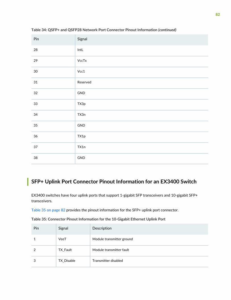
Table 34: QSFP+ and QSFP28 Network Port Connector Pinout Information (continued)
SignalPin
IntL28
VccTx29
Vcc130
Reserved31
GND32
TX3p33
TX3n34
GND35
TX1p36
TX1n37
GND38
SFP+ Uplink Port Connector Pinout Information for an EX3400 Switch
EX3400 switches have four uplink ports that support 1-gigabit SFP transceivers and 10-gigabit SFP+transceivers.
Table 35 on page 82 provides the pinout information for the SFP+ uplink port connector.
Table 35: Connector Pinout Information for the 10-Gigabit Ethernet Uplink Port
DescriptionSignalPin
Module transmitter groundVeeT1
Module transmitter faultTX_Fault2
Transmitter disabledTX_Disable3
82
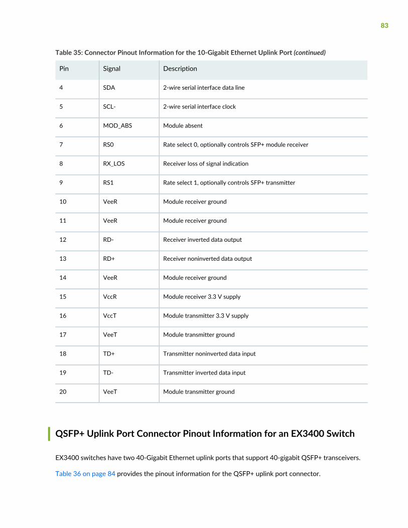
Table 35: Connector Pinout Information for the 10-Gigabit Ethernet Uplink Port (continued)
DescriptionSignalPin
2-wire serial interface data lineSDA4
2-wire serial interface clockSCL-5
Module absentMOD_ABS6
Rate select 0, optionally controls SFP+ module receiverRS07
Receiver loss of signal indicationRX_LOS8
Rate select 1, optionally controls SFP+ transmitterRS19
Module receiver groundVeeR10
Module receiver groundVeeR11
Receiver inverted data outputRD-12
Receiver noninverted data outputRD+13
Module receiver groundVeeR14
Module receiver 3.3 V supplyVccR15
Module transmitter 3.3 V supplyVccT16
Module transmitter groundVeeT17
Transmitter noninverted data inputTD+18
Transmitter inverted data inputTD-19
Module transmitter groundVeeT20
QSFP+ Uplink Port Connector Pinout Information for an EX3400 Switch
EX3400 switches have two 40-Gigabit Ethernet uplink ports that support 40-gigabit QSFP+ transceivers.
Table 36 on page 84 provides the pinout information for the QSFP+ uplink port connector.
83

Table 36: Connector Pinout Information for the 40-Gigabit Ethernet Uplink Port
SignalPin
GND1
TX2n2
TX2p3
GND4
TX4n5
TX4p6
GND7
ModSelL8
LPMode_Reset9
VccRx10
SCL11
SDA12
GND13
RX3p14
RX3n15
GND16
RX1p17
RX1n18
GND19
GND20
RX2n21
84
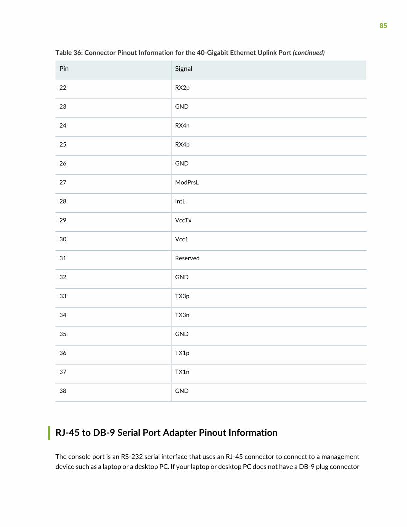
Table 36: Connector Pinout Information for the 40-Gigabit Ethernet Uplink Port (continued)
SignalPin
RX2p22
GND23
RX4n24
RX4p25
GND26
ModPrsL27
IntL28
VccTx29
Vcc130
Reserved31
GND32
TX3p33
TX3n34
GND35
TX1p36
TX1n37
GND38
RJ-45 to DB-9 Serial Port Adapter Pinout Information
The console port is an RS-232 serial interface that uses an RJ-45 connector to connect to a managementdevice such as a laptop or a desktop PC. If your laptop or desktop PC does not have a DB-9 plug connector
85
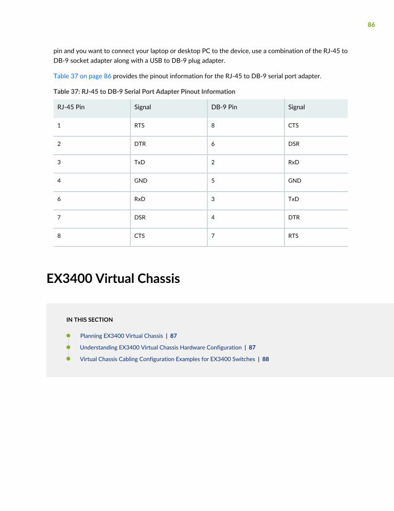
pin and you want to connect your laptop or desktop PC to the device, use a combination of the RJ-45 toDB-9 socket adapter along with a USB to DB-9 plug adapter.
Table 37 on page 86 provides the pinout information for the RJ-45 to DB-9 serial port adapter.
Table 37: RJ-45 to DB-9 Serial Port Adapter Pinout Information
SignalDB-9 PinSignalRJ-45 Pin
CTS8RTS1
DSR6DTR2
RxD2TxD3
GND5GND4
TxD3RxD6
DTR4DSR7
RTS7CTS8
EX3400 Virtual Chassis
IN THIS SECTION
Planning EX3400 Virtual Chassis | 87
Understanding EX3400 Virtual Chassis Hardware Configuration | 87
Virtual Chassis Cabling Configuration Examples for EX3400 Switches | 88
86
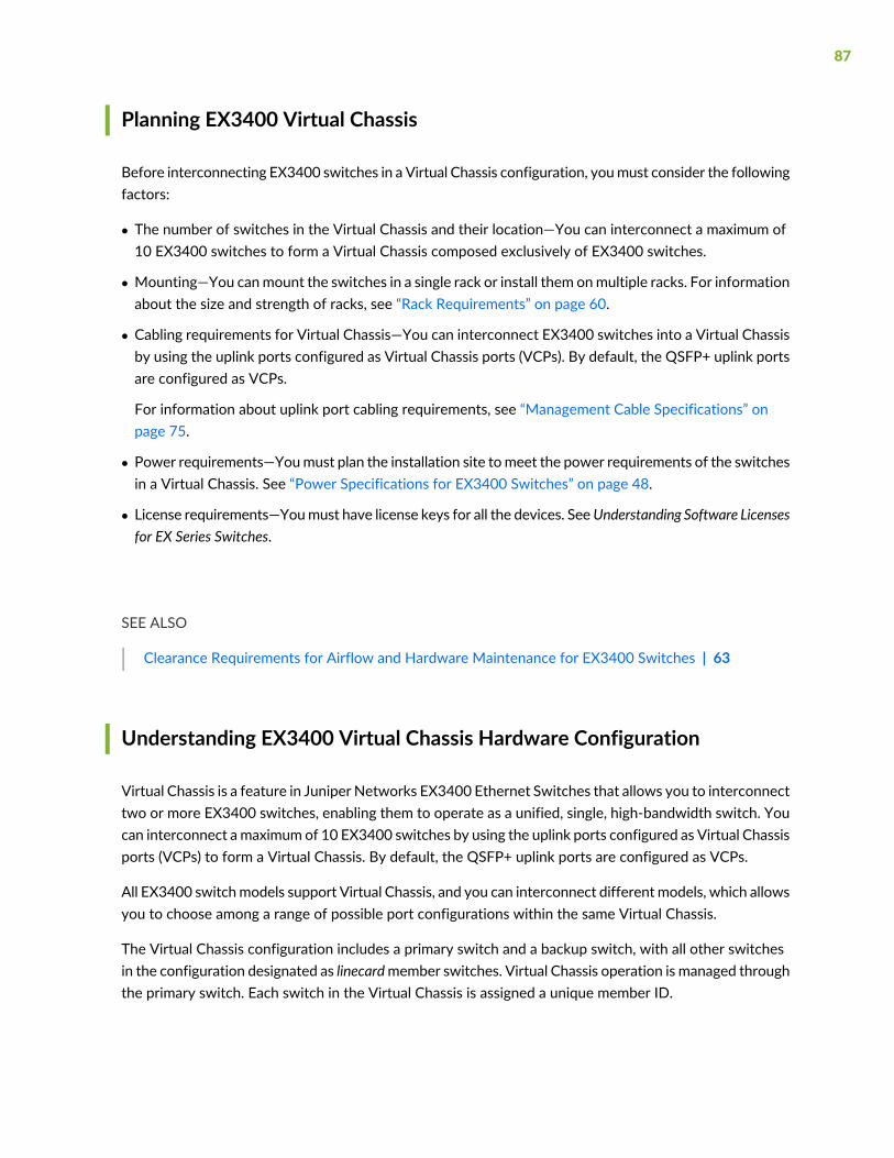
Planning EX3400 Virtual Chassis
Before interconnecting EX3400 switches in a Virtual Chassis configuration, youmust consider the followingfactors:
• The number of switches in the Virtual Chassis and their location—You can interconnect a maximum of10 EX3400 switches to form a Virtual Chassis composed exclusively of EX3400 switches.
• Mounting—You canmount the switches in a single rack or install them onmultiple racks. For informationabout the size and strength of racks, see “Rack Requirements” on page 60.
• Cabling requirements for Virtual Chassis—You can interconnect EX3400 switches into a Virtual Chassisby using the uplink ports configured as Virtual Chassis ports (VCPs). By default, the QSFP+ uplink portsare configured as VCPs.
For information about uplink port cabling requirements, see “Management Cable Specifications” onpage 75.
• Power requirements—Youmust plan the installation site tomeet the power requirements of the switchesin a Virtual Chassis. See “Power Specifications for EX3400 Switches” on page 48.
• License requirements—Youmust have license keys for all the devices. SeeUnderstanding Software Licensesfor EX Series Switches.
SEE ALSO
Clearance Requirements for Airflow and Hardware Maintenance for EX3400 Switches | 63
Understanding EX3400 Virtual Chassis Hardware Configuration
Virtual Chassis is a feature in Juniper Networks EX3400 Ethernet Switches that allows you to interconnecttwo or more EX3400 switches, enabling them to operate as a unified, single, high-bandwidth switch. Youcan interconnect amaximum of 10 EX3400 switches by using the uplink ports configured as Virtual Chassisports (VCPs) to form a Virtual Chassis. By default, the QSFP+ uplink ports are configured as VCPs.
All EX3400 switchmodels support Virtual Chassis, and you can interconnect different models, which allowsyou to choose among a range of possible port configurations within the same Virtual Chassis.
The Virtual Chassis configuration includes a primary switch and a backup switch, with all other switchesin the configuration designated as linecardmember switches. Virtual Chassis operation is managed throughthe primary switch. Each switch in the Virtual Chassis is assigned a unique member ID.
87
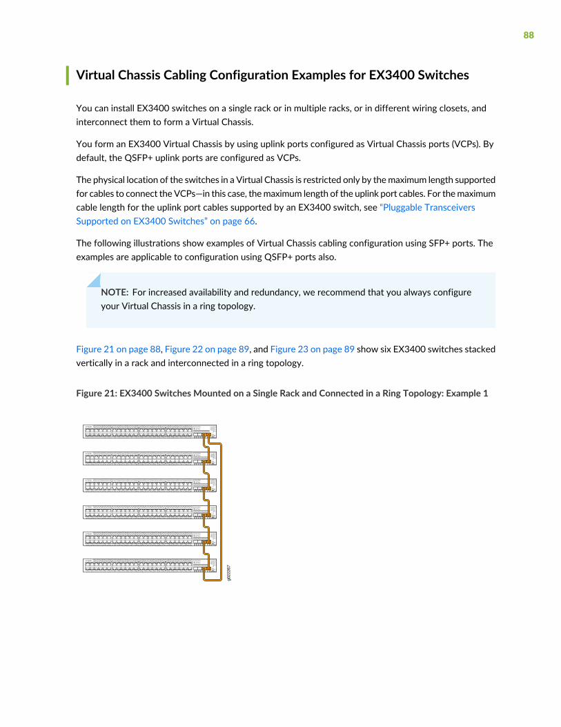
Virtual Chassis Cabling Configuration Examples for EX3400 Switches
You can install EX3400 switches on a single rack or in multiple racks, or in different wiring closets, andinterconnect them to form a Virtual Chassis.
You form an EX3400 Virtual Chassis by using uplink ports configured as Virtual Chassis ports (VCPs). Bydefault, the QSFP+ uplink ports are configured as VCPs.
The physical location of the switches in a Virtual Chassis is restricted only by themaximum length supportedfor cables to connect the VCPs—in this case, themaximum length of the uplink port cables. For themaximumcable length for the uplink port cables supported by an EX3400 switch, see “Pluggable TransceiversSupported on EX3400 Switches” on page 66.
The following illustrations show examples of Virtual Chassis cabling configuration using SFP+ ports. Theexamples are applicable to configuration using QSFP+ ports also.
NOTE: For increased availability and redundancy, we recommend that you always configureyour Virtual Chassis in a ring topology.
Figure 21 on page 88, Figure 22 on page 89, and Figure 23 on page 89 show six EX3400 switches stackedvertically in a rack and interconnected in a ring topology.
Figure 21: EX3400 Switches Mounted on a Single Rack and Connected in a Ring Topology: Example 1
g022
267
88
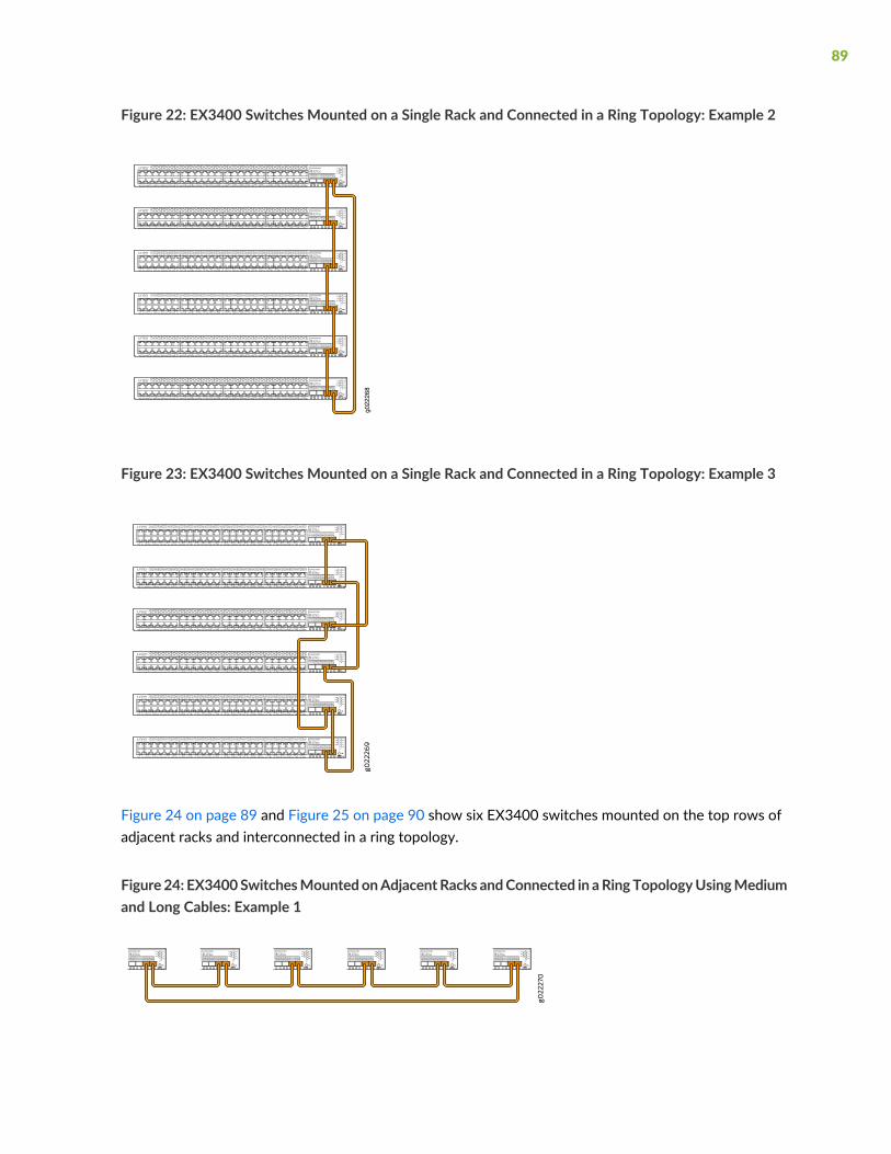
Figure 22: EX3400 Switches Mounted on a Single Rack and Connected in a Ring Topology: Example 2
g022
268
Figure 23: EX3400 Switches Mounted on a Single Rack and Connected in a Ring Topology: Example 3
Figure 24 on page 89 and Figure 25 on page 90 show six EX3400 switches mounted on the top rows ofadjacent racks and interconnected in a ring topology.
Figure 24: EX3400SwitchesMountedonAdjacentRacks andConnected in aRingTopologyUsingMediumand Long Cables: Example 1
89

Figure 25: EX3400SwitchesMountedonAdjacentRacks andConnected in aRingTopologyUsingMediumand Long Cables: Example 2
g022
271
90
3CHAPTER
Initial Installation and Configuration
Unpacking and Mounting the EX3400 Switch | 92
Connecting the EX3400 to Power | 108
Connecting the EX3400 to External Devices | 122
Connecting the EX3400 to the Network | 126
Configuring Junos OS on the EX3400 | 130
Dashboard for EX Series Switches | 164
Unpacking and Mounting the EX3400 Switch
IN THIS SECTION
Unpacking an EX3400 Switch | 92
Parts Inventory (Packing List) for an EX3400 Switch | 93
Register Products—Mandatory to Validate SLAs | 94
Installing and Connecting an EX3400 Switch | 95
Installing and Removing EX3400 Switch Hardware Components | 96
Mounting an EX3400 Switch on a Desk or Other Level Surface | 96
Mounting an EX3400 Switch on Two Posts in a Rack or Cabinet | 98
Mounting an EX3400 Switch on Four Posts in a Rack or Cabinet | 101
Mounting an EX3400 Switch in a Recessed Position in a Rack or Cabinet | 104
Mounting an EX3400 Switch on a Wall | 105
Unpacking an EX3400 Switch
The EX3400 switches are shipped in a cardboard carton, secured with foam packing material. The cartonalso contains an accessory box.
CAUTION: EX3400 switches are maximally protected inside the shipping carton. Donot unpack the switches until you are ready to begin installation.
To unpack the switch:
1. Move the shipping carton to a staging area as close to the installation site as possible, but where youhave enough room to remove the system components.
2. Position the carton so that the arrows are pointing up.
3. Open the top flaps on the shipping carton.
4. Remove the accessory box and verify the contents in it against the parts inventory on the label attachedto the carton.
92

5. Pull out the packing material holding the switch in place.
6. Verify the chassis components received against the packing list included with the switch. An inventoryof parts provided with the switch is provided in “Parts Inventory (Packing List) for an EX3400 Switch”on page 93.
7. Save the shipping carton and packing materials in case you need to move or ship the switch later.
Parts Inventory (Packing List) for an EX3400 Switch
The EX3400 switches are shipped in a cardboard carton, secured with foam packing material. The cartonalso contains an accessory box.
The switch shipment includes a packing list. Check the parts you receive in the switch shipping cartonagainst the items on the packing list. The parts shipped depend on the configuration you order.
If any part on the packing list is missing, contact your customer service representative or contact Junipercustomer care from within the U.S. or Canada by telephone at 1-888-314-5822. For international-dial ordirect-dial options in countries without toll-free numbers, seehttps://www.juniper.net/support/requesting-support.html.
Table 38 on page 93 lists the parts and their quantities in the packing list.
Table 38: Parts List for an EX3400 Switch
QuantityComponent
1Switch with one power supply and two fan modules
1AC power cord appropriate for your geographical location (only for AC switch models)
1Power cord retainer clip (only for AC switch models)
2Mounting brackets
8Mounting screws to attach the mounting brackets to the switch chassis
4Rubber feet
1RJ-45 cable and RJ-45 to DB-9 serial port adapter
1Documentation Roadmap
93
Table 38: Parts List for an EX3400 Switch (continued)
QuantityComponent
1Juniper Networks Product Warranty
1End User License Agreement
NOTE: Youmust providemounting screws that are appropriate for your rack or cabinet tomountthe chassis on a rack or a cabinet.
Register Products—Mandatory to Validate SLAs
Register all new Juniper Networks hardware products and changes to an existing installed product usingthe Juniper Networks website to activate your hardware replacement service-level agreements (SLAs).
CAUTION: Register product serial numbers on the Juniper Networks website andupdate the installation base data if there is any addition or change to the installationbase or if the installation base is moved. Juniper Networkswill not be held accountablefor not meeting the hardware replacement service-level agreement for products thatdo not have registered serial numbers or accurate installation base data.
Register your product(s) at https://tools.juniper.net/svcreg/SRegSerialNum.jsp.Update your installation base athttps://www.juniper.net/customers/csc/management/updateinstallbase.jsp.
94

Installing and Connecting an EX3400 Switch
To install and connect an EX3400 switch:
1. Follow instructions in “Unpacking an EX3400 Switch” on page 92.
2. Mount the switch by following instructions appropriate for your site:
• “Mounting an EX3400 Switch on a Desk or Other Level Surface” on page 96 (using the rubber feetprovided)
• “Mounting an EX3400 Switch on Two Posts in a Rack or Cabinet” on page 98 (using the mountingbrackets provided)
• “Mounting an EX3400 Switch on Four Posts in a Rack or Cabinet” on page 101 (using the separatelyorderable four-post rack-mount kit)
• “Mounting an EX3400 Switch in a Recessed Position in a Rack or Cabinet” on page 104 (using the2-in.-recess front-mounting brackets from the separately orderable four-post rack-mount kit)
• “Mounting an EX3400 Switch on aWall” on page 105 (using the separately orderable wall-mount kit)
3. Follow instructions in “Connect Earth Ground to an EX Series Switch” on page 109.
4. Follow instructions in “Connecting AC Power to an EX3400 Switch” on page 116 or “Connecting DCPower to an EX3400 Switch” on page 118.
5. Perform initial configuration of the switch by following instructions in “Connecting and Configuring anEX Series Switch (CLI Procedure)” on page 150.
6. Set the switch’s management options by following the appropriate instructions:
• Connect a Device to a Network for Out-of-Band Management on page 122
• Connect a Device to a Management Console Using an RJ-45 Connector on page 123
SEE ALSO
Rack Requirements | 60
Cabinet Requirements | 62
Clearance Requirements for Airflow and Hardware Maintenance for EX3400 Switches | 63
95
Installing and Removing EX3400 Switch Hardware Components
The EX3400 switch chassis is a rigid sheet-metal structure that houses the hardware components. Thefield-replaceable units (FRUs) in EX3400 switches are:
• Power supplies
• Fan modules
• Transceivers
The power supplies and fan modules are hot-removable and hot-insertable: You can remove and replacethem without powering off the switch or disrupting switch functions.
See these topics for instructions for installing and removing components:
• Installing an AC Power Supply in an EX3400 Switch on page 199
• Removing an AC Power Supply from an EX3400 Switch on page 197
• Installing a Fan Module in an EX3400 Switch on page 195
• Removing a Fan Module from an EX3400 Switch on page 194
• Installing a DC Power Supply in an EX3400 Switch on page 202
• Removing a DC Power Supply from an EX3400 Switch on page 200
• Install a Transceiver on page 126
• Remove a Transceiver on page 207
SEE ALSO
EX3400 Cooling System | 38
AC Power Supply in EX3400 Switches | 41
Pluggable Transceivers Supported on EX3400 Switches | 66
Mounting an EX3400 Switch on a Desk or Other Level Surface
You can mount an EX3400 switch on a desk or other level surface by using the four rubber feet that areshipped with the switch. The rubber feet stabilize the chassis.
Before mounting the switch on a desk or other level surface:
96
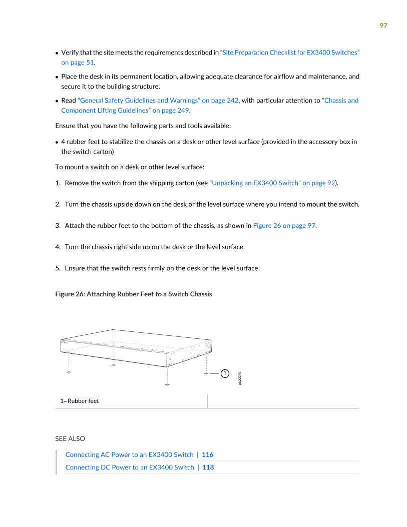
• Verify that the sitemeets the requirements described in “Site Preparation Checklist for EX3400 Switches”on page 51.
• Place the desk in its permanent location, allowing adequate clearance for airflow and maintenance, andsecure it to the building structure.
• Read “General Safety Guidelines and Warnings” on page 242, with particular attention to “Chassis andComponent Lifting Guidelines” on page 249.
Ensure that you have the following parts and tools available:
• 4 rubber feet to stabilize the chassis on a desk or other level surface (provided in the accessory box inthe switch carton)
To mount a switch on a desk or other level surface:
1. Remove the switch from the shipping carton (see “Unpacking an EX3400 Switch” on page 92).
2. Turn the chassis upside down on the desk or the level surface where you intend to mount the switch.
3. Attach the rubber feet to the bottom of the chassis, as shown in Figure 26 on page 97.
4. Turn the chassis right side up on the desk or the level surface.
5. Ensure that the switch rests firmly on the desk or the level surface.
Figure 26: Attaching Rubber Feet to a Switch Chassis
1—Rubber feet
SEE ALSO
Connecting AC Power to an EX3400 Switch | 116
Connecting DC Power to an EX3400 Switch | 118
97

Connecting and Configuring an EX Series Switch (CLI Procedure) | 150
Clearance Requirements for Airflow and Hardware Maintenance for EX3400 Switches | 63
Mounting an EX3400 Switch on Two Posts in a Rack or Cabinet
You can mount an EX3400 switch on two posts of a 19-in. rack or cabinet by using the mounting bracketsprovided with the switch. (The remainder of this topic uses rack to mean rack or cabinet.)
You can mount the switch on four posts of a four-post rack by using the mounting brackets provided withthe separately orderable four-post rack-mount kit. See “Mounting an EX3400 Switch on Four Posts in aRack or Cabinet” on page 101.
NOTE: If you need to mount the switch in a recessed position on either a two-post rack or afour-post rack, you can use the 2-in.-recess front-mounting brackets provided in the separatelyorderable four-post rack-mount kit.
Before mounting the switch on two posts in a rack:
• Verify that the sitemeets the requirements described in “Site Preparation Checklist for EX3400 Switches”on page 51.
• Place the rack in its permanent location, allowing adequate clearance for airflow and maintenance, andsecure it to the building structure.
• Read “General Safety Guidelines and Warnings” on page 242, with particular attention to “Chassis andComponent Lifting Guidelines” on page 249.
Ensure that you have the following parts and tools available:
• Phillips (+) screwdriver, number 2 (not provided)
• 2 mounting brackets and 8 mounting screws (provided)
• Screws to secure the chassis to the rack (not provided)
• 2-in.-recess front-mounting brackets (from the separately orderable four-post rack-mount kit) if you willmount the switch in a recessed position
NOTE: One person must be available to lift the switch while another secures the switch to therack.
98
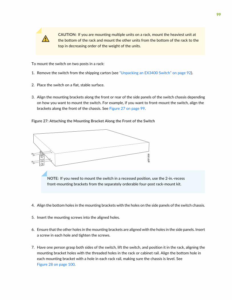
CAUTION: If you are mounting multiple units on a rack, mount the heaviest unit atthe bottom of the rack and mount the other units from the bottom of the rack to thetop in decreasing order of the weight of the units.
To mount the switch on two posts in a rack:
1. Remove the switch from the shipping carton (see “Unpacking an EX3400 Switch” on page 92).
2. Place the switch on a flat, stable surface.
3. Align the mounting brackets along the front or rear of the side panels of the switch chassis dependingon how you want to mount the switch. For example, if you want to front-mount the switch, align thebrackets along the front of the chassis. See Figure 27 on page 99.
Figure 27: Attaching the Mounting Bracket Along the Front of the Switch
g021
209
NOTE: If you need to mount the switch in a recessed position, use the 2-in.-recessfront-mounting brackets from the separately orderable four-post rack-mount kit.
4. Align the bottom holes in themounting brackets with the holes on the side panels of the switch chassis.
5. Insert the mounting screws into the aligned holes.
6. Ensure that the other holes in themounting brackets are alignedwith the holes in the side panels. Inserta screw in each hole and tighten the screws.
7. Have one person grasp both sides of the switch, lift the switch, and position it in the rack, aligning themounting bracket holes with the threaded holes in the rack or cabinet rail. Align the bottom hole ineach mounting bracket with a hole in each rack rail, making sure the chassis is level. SeeFigure 28 on page 100.
99
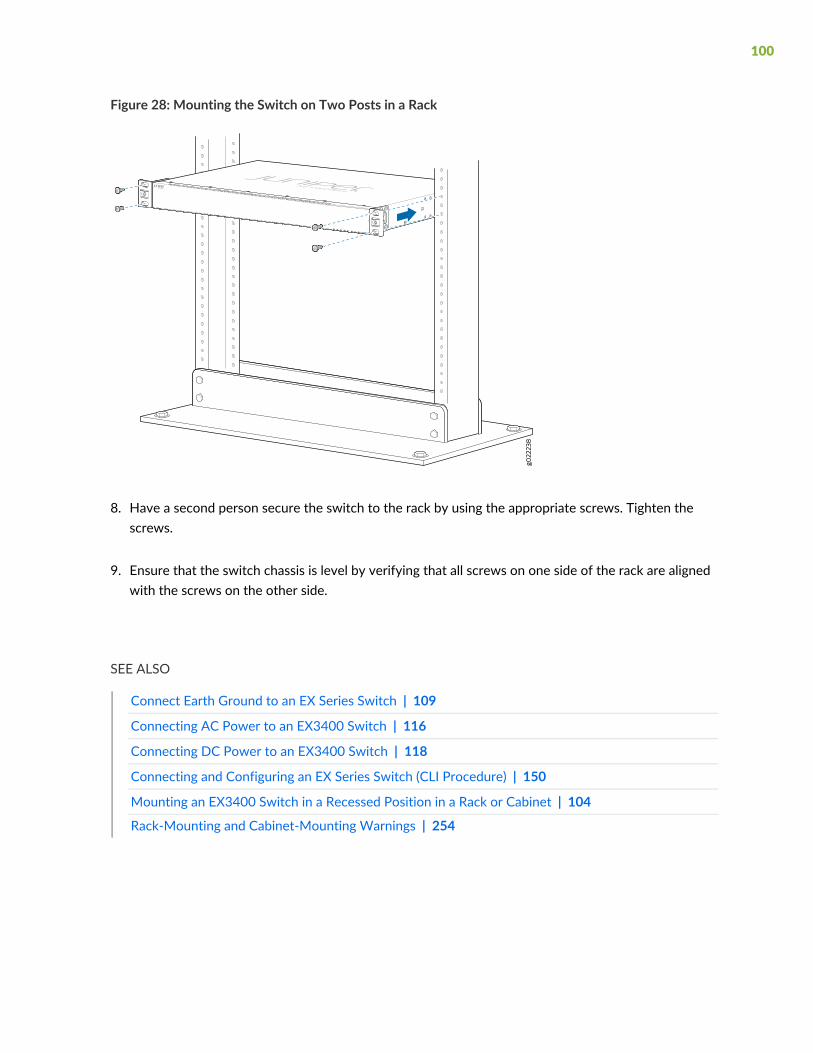
Figure 28: Mounting the Switch on Two Posts in a Rack
8. Have a second person secure the switch to the rack by using the appropriate screws. Tighten thescrews.
9. Ensure that the switch chassis is level by verifying that all screws on one side of the rack are alignedwith the screws on the other side.
SEE ALSO
Connect Earth Ground to an EX Series Switch | 109
Connecting AC Power to an EX3400 Switch | 116
Connecting DC Power to an EX3400 Switch | 118
Connecting and Configuring an EX Series Switch (CLI Procedure) | 150
Mounting an EX3400 Switch in a Recessed Position in a Rack or Cabinet | 104
Rack-Mounting and Cabinet-Mounting Warnings | 254
100
Mounting an EX3400 Switch on Four Posts in a Rack or Cabinet
You canmount an EX3400 switch on four posts of a 19-in. rack or cabinet by using the separately orderablefour-post rack-mount kit. (The remainder of this topic uses rack to mean rack or cabinet.)
You canmount the switch on two posts in either a two-post rack or a four-post rack by using themountingbrackets provided with the switch. See “Mounting an EX3400 Switch on Two Posts in a Rack or Cabinet”on page 98.
NOTE: If you need to mount the switch in a recessed position on either a two-post rack or afour-post rack, you can use the 2-in.-recess front-mounting brackets provided in the separatelyorderable four-post rack-mount kit.
Before mounting the switch on four posts in a rack:
• Verify that the sitemeets the requirements described in “Site Preparation Checklist for EX3400 Switches”on page 51.
• Place the rack in its permanent location, allowing adequate clearance for airflow and maintenance, andsecure it to the building structure.
• Read “General Safety Guidelines and Warnings” on page 242, with particular attention to “Chassis andComponent Lifting Guidelines” on page 249.
Ensure that you have the following parts and tools available:
• Phillips (+) screwdriver, number 2
• 6 flat-head 4-40 mounting screws (provided with the four-post rack-mount kit)
• 8 flat-head 4x6-mm Phillips mounting screws (provided with the four-post rack-mount kit)
• One pair each of flush or 2-in.-recess front-mounting brackets (provided with the four-post rack-mountkit)
• One pair of side mounting-rails (provided with the four-post rack-mount kit)
• One pair of rear-mounting blades (provided with the four-post rack-mount kit)
• Screws to secure the chassis and the rear-mounting blades to the rack (not provided)
NOTE: One person must be available to lift the switch while another secures the switch to therack.
101
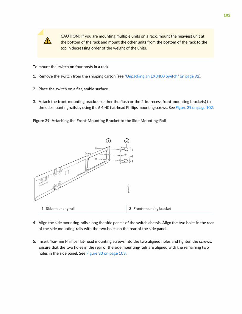
CAUTION: If you are mounting multiple units on a rack, mount the heaviest unit atthe bottom of the rack and mount the other units from the bottom of the rack to thetop in decreasing order of the weight of the units.
To mount the switch on four posts in a rack:
1. Remove the switch from the shipping carton (see “Unpacking an EX3400 Switch” on page 92).
2. Place the switch on a flat, stable surface.
3. Attach the front-mounting brackets (either the flush or the 2-in.-recess front-mounting brackets) tothe sidemounting-rails by using the 6 4-40 flat-head Phillipsmounting screws. See Figure 29 on page 102.
Figure 29: Attaching the Front-Mounting Bracket to the Side Mounting-Rail
2—1— Front-mounting bracketSide mounting-rail
4. Align the side mounting-rails along the side panels of the switch chassis. Align the two holes in the rearof the side mounting-rails with the two holes on the rear of the side panel.
5. Insert 4x6-mm Phillips flat-head mounting screws into the two aligned holes and tighten the screws.Ensure that the two holes in the rear of the side mounting-rails are aligned with the remaining twoholes in the side panel. See Figure 30 on page 103.
102
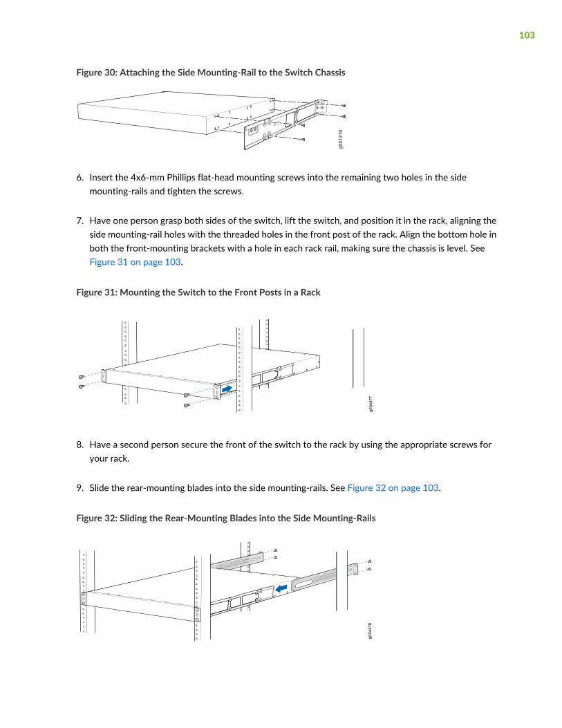
Figure 30: Attaching the Side Mounting-Rail to the Switch Chassis
g021
210
6. Insert the 4x6-mm Phillips flat-head mounting screws into the remaining two holes in the sidemounting-rails and tighten the screws.
7. Have one person grasp both sides of the switch, lift the switch, and position it in the rack, aligning theside mounting-rail holes with the threaded holes in the front post of the rack. Align the bottom hole inboth the front-mounting brackets with a hole in each rack rail, making sure the chassis is level. SeeFigure 31 on page 103.
Figure 31: Mounting the Switch to the Front Posts in a Rack
g004
477
8. Have a second person secure the front of the switch to the rack by using the appropriate screws foryour rack.
9. Slide the rear-mounting blades into the side mounting-rails. See Figure 32 on page 103.
Figure 32: Sliding the Rear-Mounting Blades into the Side Mounting-Rails
g004
478
103

10.Attach the rear-mounting blades to the rear post by using the appropriate screws for your rack. Tightenthe screws.
11. Ensure that the switch chassis is level by verifying that all the screws on the front of the rack are alignedwith the screws at the back of the rack.
SEE ALSO
Connect Earth Ground to an EX Series Switch | 109
Connecting AC Power to an EX3400 Switch | 116
Connecting DC Power to an EX3400 Switch | 118
Connecting and Configuring an EX Series Switch (CLI Procedure) | 150
Mounting an EX3400 Switch in a Recessed Position in a Rack or Cabinet | 104
Rack-Mounting and Cabinet-Mounting Warnings | 254
Mounting an EX3400 Switch in a Recessed Position in a Rack or Cabinet
You can mount an EX3400 switch in a rack or cabinet such that the switch is recessed inside the rack fromthe front of the rack by 2 inches. You can use the 2-in.-recess front-mounting brackets provided in theseparately orderable four-post rack-mount kit to mount the switch in a recessed position.
Reasons that you might want to mount the switch in a recessed position include:
• You aremounting the switch in a cabinet and the cabinet doors do not close completely unless the switchis recessed.
• The switch you are mounting has transceivers installed in the uplink ports and the transceivers in theuplink ports protrude from the front of the switch.
To mount the switch in a recessed position on four posts, follow the instructions in “Mounting an EX3400Switch on Four Posts in a Rack or Cabinet” on page 101. Tomount the switch in a recessed position on twoposts, follow the instructions in “Mounting an EX3400 Switch on Two Posts in a Rack or Cabinet” onpage 98.
SEE ALSO
Connect Earth Ground to an EX Series Switch | 109
Rack-Mounting and Cabinet-Mounting Warnings | 254
104

Mounting an EX3400 Switch on a Wall
You can mount an EX3400 switch on a wall by using the separately orderable wall-mount kit.
Before mounting the switch on a wall:
• Verify that the sitemeets the requirements described in “Site Preparation Checklist for EX3400 Switches”on page 51.
• Read “General Safety Guidelines and Warnings” on page 242, with particular attention to “Chassis andComponent Lifting Guidelines” on page 249.
Ensure that you have the following parts and tools available:
• 2 wall-mounting brackets (provided in the wall-mount kit)
• 12 wall-mounting bracket screws (provided in the wall-mount kit)
• 6 mounting screws (8-32 x 1.25 in. or M4 x 30 mm) (not provided)
• Hollow wall anchors rated to support up to 75 lb (34 kg) if you are not screwing the screws directly intowall studs (not provided)
• Phillips (+) screwdriver, number 2
To mount one or two switches on a wall:
1. Remove the switch from the shipping carton (see “Unpacking an EX3400 Switch” on page 92).
2. Attach the wall-mounting brackets to the sides of the chassis using four wall-mounting bracket screwson each side, as shown in Figure 33 on page 106.
105
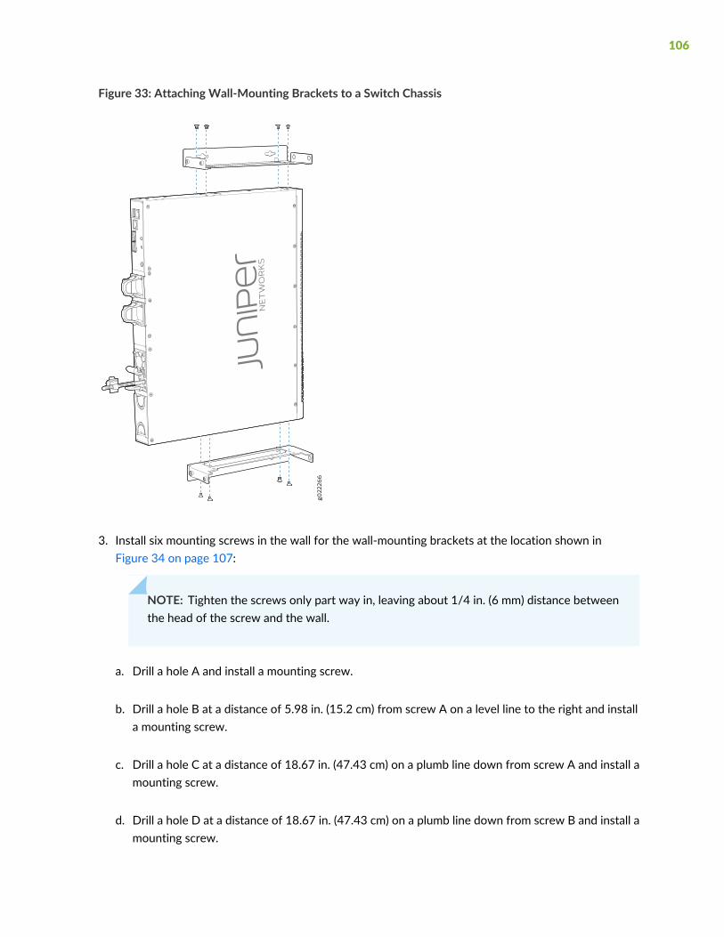
Figure 33: Attaching Wall-Mounting Brackets to a Switch Chassis
3. Install six mounting screws in the wall for the wall-mounting brackets at the location shown inFigure 34 on page 107:
NOTE: Tighten the screws only part way in, leaving about 1/4 in. (6 mm) distance betweenthe head of the screw and the wall.
a. Drill a hole A and install a mounting screw.
b. Drill a hole B at a distance of 5.98 in. (15.2 cm) from screw A on a level line to the right and installa mounting screw.
c. Drill a hole C at a distance of 18.67 in. (47.43 cm) on a plumb line down from screw A and install amounting screw.
d. Drill a hole D at a distance of 18.67 in. (47.43 cm) on a plumb line down from screw B and install amounting screw.
106
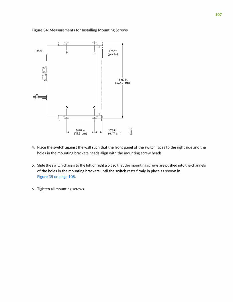
Figure 34: Measurements for Installing Mounting Screws
4. Place the switch against the wall such that the front panel of the switch faces to the right side and theholes in the mounting brackets heads align with the mounting screw heads.
5. Slide the switch chassis to the left or right a bit so that themounting screws are pushed into the channelsof the holes in the mounting brackets until the switch rests firmly in place as shown inFigure 35 on page 108.
6. Tighten all mounting screws.
107
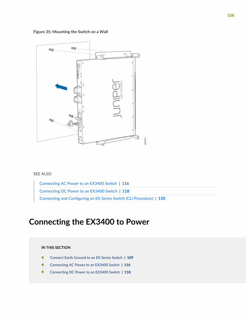
Figure 35: Mounting the Switch on a Wall
g022274
SEE ALSO
Connecting AC Power to an EX3400 Switch | 116
Connecting DC Power to an EX3400 Switch | 118
Connecting and Configuring an EX Series Switch (CLI Procedure) | 150
Connecting the EX3400 to Power
IN THIS SECTION
Connect Earth Ground to an EX Series Switch | 109
Connecting AC Power to an EX3400 Switch | 116
Connecting DC Power to an EX3400 Switch | 118
108

Connect Earth Ground to an EX Series Switch
IN THIS SECTION
Parts and Tools Required for Connecting an EX Series Switch to Earth Ground | 109
Special Instructions to Follow Before Connecting Earth Ground to an EX Series Switch | 114
Connecting Earth Ground to an EX Series Switch | 115
To ensure proper operation and to meet safety and electromagnetic interference (EMI) requirements, youmust connect an EX Series switch to earth ground before you connect power to the switch. You must usethe protective earthing terminal on the switch chassis to connect the switch to earth ground (seeFigure 37 on page 116).
You must install the EX Series switch in a restricted–access location and ensure that the chassis is alwaysproperly grounded. EX Series switches have a two–hole protective grounding terminal provided on thechassis. See Table 39 on page 110 for the location of the earthing terminals on various EX Series switches.We recommend that you use the protective grounding terminal as the preferred method for groundingthe chassis regardless of the power supply configuration. However, if additional grounding methods areavailable, you can also use those methods. For example, you can use the grounding wire in the power cordof an AC power supply or use the grounding terminal or lug on a DC power supply. This systemwas testedto meet or exceed all applicable EMC regulatory requirements with the two-hole protective groundingterminal connected correctly.
Ensure that a licensed electrician has attached an appropriate grounding lug to the grounding cable yousupply. Using a grounding cable with an incorrectly attached lug can damage the switch.
Parts and Tools Required for Connecting an EX Series Switch to Earth Ground
Before you begin connecting an EX Series switch to earth ground, ensure you have the parts and toolsrequired for your switch.
Table 39 on page 110 lists the earthing terminal location, grounding cable and lug specifications, and partsneeded for connecting an EX Series switch to earth ground.
109
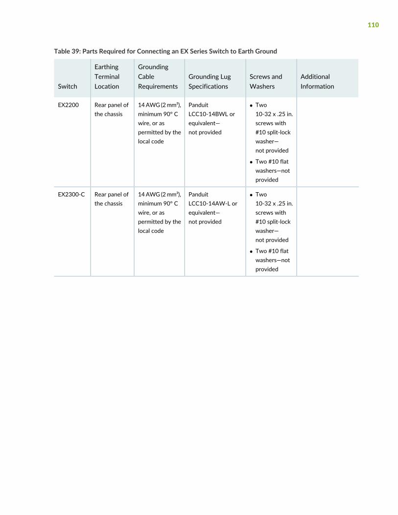
Table 39: Parts Required for Connecting an EX Series Switch to Earth Ground
AdditionalInformation
Screws andWashers
Grounding LugSpecifications
GroundingCableRequirements
EarthingTerminalLocationSwitch
• Two10-32 x .25 in.screws with#10 split-lockwasher—not provided
• Two #10 flatwashers—notprovided
PanduitLCC10-14BWL orequivalent—not provided
14AWG (2mm²),minimum 90° Cwire, or aspermitted by thelocal code
Rear panel ofthe chassis
EX2200
• Two10-32 x .25 in.screws with#10 split-lockwasher—not provided
• Two #10 flatwashers—notprovided
PanduitLCC10-14AW-L orequivalent—not provided
14AWG (2mm²),minimum 90° Cwire, or aspermitted by thelocal code
Rear panel ofthe chassis
EX2300-C
110
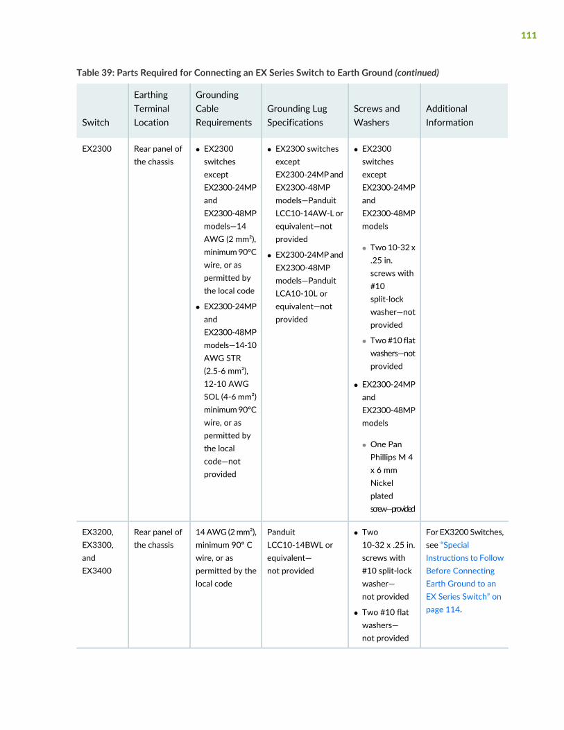
Table 39: Parts Required for Connecting an EX Series Switch to Earth Ground (continued)
AdditionalInformation
Screws andWashers
Grounding LugSpecifications
GroundingCableRequirements
EarthingTerminalLocationSwitch
• EX2300switchesexceptEX2300-24MPandEX2300-48MPmodels
• Two10-32 x.25 in.screws with#10split-lockwasher—notprovided
• Two#10 flatwashers—notprovided
• EX2300-24MPandEX2300-48MPmodels
• One PanPhillips M 4x 6 mmNickelplatedscrew—provided
• EX2300 switchesexceptEX2300-24MPandEX2300-48MPmodels—PanduitLCC10-14AW-Lorequivalent—notprovided
• EX2300-24MPandEX2300-48MPmodels—PanduitLCA10-10L orequivalent—notprovided
• EX2300switchesexceptEX2300-24MPandEX2300-48MPmodels—14AWG (2 mm²),minimum90°Cwire, or aspermitted bythe local code
• EX2300-24MPandEX2300-48MPmodels—14-10AWG STR(2.5-6 mm²),12-10 AWGSOL (4-6 mm²)minimum90°Cwire, or aspermitted bythe localcode—notprovided
Rear panel ofthe chassis
EX2300
For EX3200 Switches,see “SpecialInstructions to FollowBefore ConnectingEarth Ground to anEX Series Switch” onpage 114.
• Two10-32 x .25 in.screws with#10 split-lockwasher—not provided
• Two #10 flatwashers—not provided
PanduitLCC10-14BWL orequivalent—not provided
14AWG (2mm²),minimum 90° Cwire, or aspermitted by thelocal code
Rear panel ofthe chassis
EX3200,EX3300,andEX3400
111
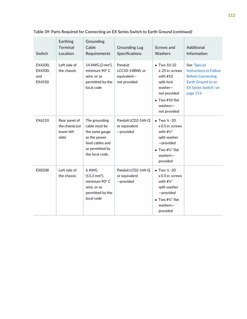
Table 39: Parts Required for Connecting an EX Series Switch to Earth Ground (continued)
AdditionalInformation
Screws andWashers
Grounding LugSpecifications
GroundingCableRequirements
EarthingTerminalLocationSwitch
See “SpecialInstructions to FollowBefore ConnectingEarth Ground to anEX Series Switch” onpage 114.
• Two 10-32x .25 in. screwswith #10split-lockwasher—not provided
• Two #10 flatwashers—not provided
PanduitLCC10-14BWL orequivalent—not provided
14AWG (2mm²),minimum 90° Cwire, or aspermitted by thelocal code
Left side ofthe chassis
EX4200,EX4500,andEX4550
• Two ¼ -20x 0.5 in. screwswith #¼”split-washer—provided
• Two #¼” flatwashers—provided
Panduit LCD2-14A-Qor equivalent—provided
The groundingcable must bethe same gaugeas the powerfeed cables andas permitted bythe local code.
Rear panel ofthe chassis (onlower leftside)
EX6210
• Two ¼ -20x 0.5 in. screwswith #¼”split-washer—provided
• Two #¼” flatwashers—provided
Panduit LCD2-14A-Qor equivalent—provided
6 AWG(13.3 mm²),minimum 90° Cwire, or aspermitted by thelocal code
Left side ofthe chassis
EX8208
112
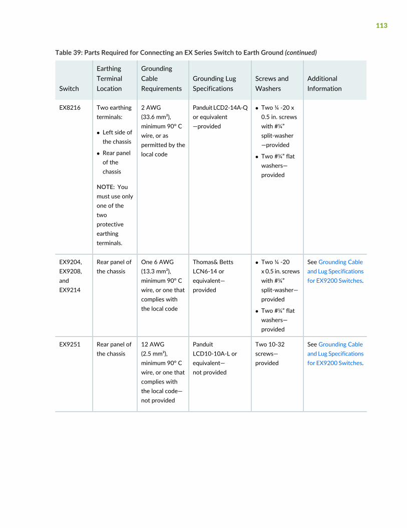
Table 39: Parts Required for Connecting an EX Series Switch to Earth Ground (continued)
AdditionalInformation
Screws andWashers
Grounding LugSpecifications
GroundingCableRequirements
EarthingTerminalLocationSwitch
• Two ¼ -20 x0.5 in. screwswith #¼”split-washer—provided
• Two #¼” flatwashers—provided
Panduit LCD2-14A-Qor equivalent—provided
2 AWG(33.6 mm²),minimum 90° Cwire, or aspermitted by thelocal code
Two earthingterminals:
• Left side ofthe chassis
• Rear panelof thechassis
NOTE: Youmust use onlyone of thetwoprotectiveearthingterminals.
EX8216
See Grounding Cableand Lug Specificationsfor EX9200 Switches.
• Two ¼ -20x 0.5 in. screwswith #¼”split-washer—provided
• Two #¼” flatwashers—provided
Thomas& BettsLCN6-14 orequivalent—provided
One 6 AWG(13.3 mm²),minimum 90° Cwire, or one thatcomplies withthe local code
Rear panel ofthe chassis
EX9204,EX9208,andEX9214
See Grounding Cableand Lug Specificationsfor EX9200 Switches.
Two 10-32screws—provided
PanduitLCD10-10A-L orequivalent—not provided
12 AWG(2.5 mm²),minimum 90° Cwire, or one thatcomplies withthe local code—not provided
Rear panel ofthe chassis
EX9251
113
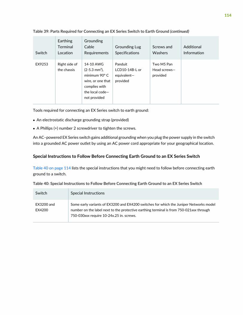
Table 39: Parts Required for Connecting an EX Series Switch to Earth Ground (continued)
AdditionalInformation
Screws andWashers
Grounding LugSpecifications
GroundingCableRequirements
EarthingTerminalLocationSwitch
Two M5 PanHead screws—provided
PanduitLCD10-14B-L orequivalent—provided
14-10 AWG(2-5.3 mm²),minimum 90° Cwire, or one thatcomplies withthe local code—not provided
Right side ofthe chassis
EX9253
Tools required for connecting an EX Series switch to earth ground:
• An electrostatic discharge grounding strap (provided)
• A Phillips (+) number 2 screwdriver to tighten the screws.
An AC–powered EX Series switch gains additional groundingwhen you plug the power supply in the switchinto a grounded AC power outlet by using an AC power cord appropriate for your geographical location.
Special Instructions to Follow Before Connecting Earth Ground to an EX Series Switch
Table 40 on page 114 lists the special instructions that you might need to follow before connecting earthground to a switch.
Table 40: Special Instructions to Follow Before Connecting Earth Ground to an EX Series Switch
Special InstructionsSwitch
Some early variants of EX3200 and EX4200 switches for which the Juniper Networks modelnumber on the label next to the protective earthing terminal is from 750-021xxx through750-030xxx require 10-24x.25 in. screws.
EX3200 andEX4200
114
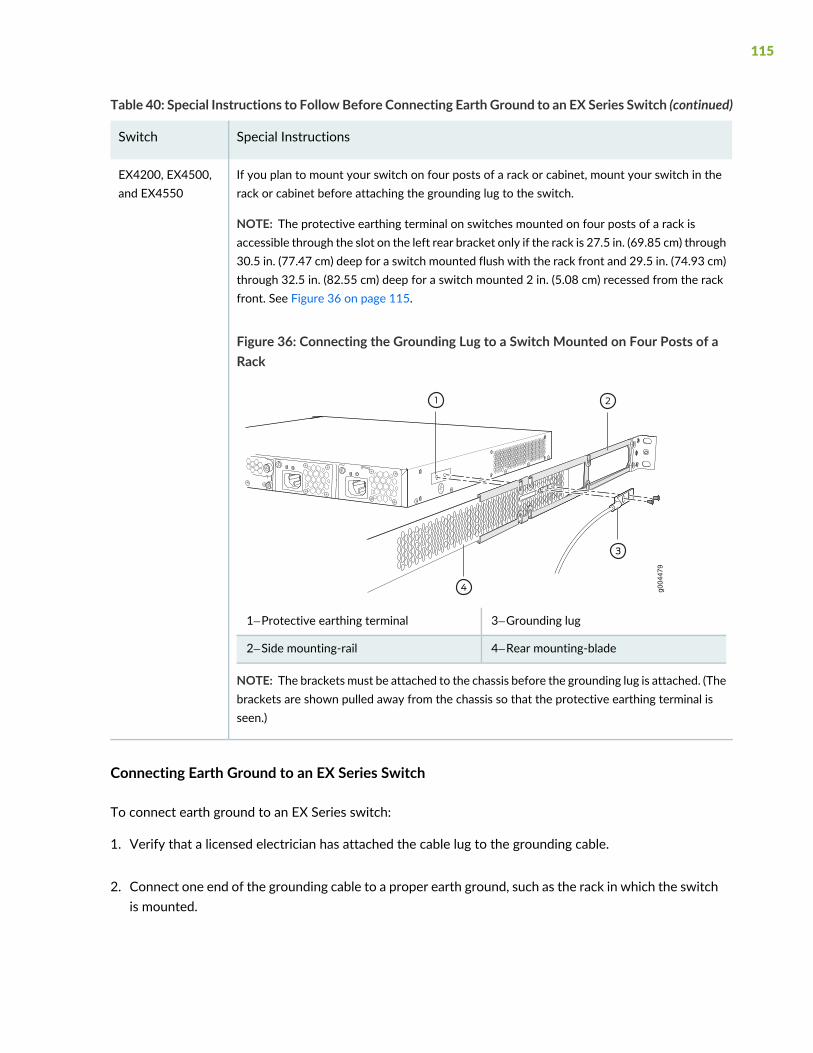
Table 40: Special Instructions to FollowBefore Connecting Earth Ground to an EX Series Switch (continued)
Special InstructionsSwitch
If you plan to mount your switch on four posts of a rack or cabinet, mount your switch in therack or cabinet before attaching the grounding lug to the switch.
NOTE: The protective earthing terminal on switches mounted on four posts of a rack isaccessible through the slot on the left rear bracket only if the rack is 27.5 in. (69.85 cm) through30.5 in. (77.47 cm) deep for a switch mounted flush with the rack front and 29.5 in. (74.93 cm)through 32.5 in. (82.55 cm) deep for a switch mounted 2 in. (5.08 cm) recessed from the rackfront. See Figure 36 on page 115.
Figure 36: Connecting the Grounding Lug to a Switch Mounted on Four Posts of aRack
g004
479
3—1— Grounding lugProtective earthing terminal
4—2— Rear mounting-bladeSide mounting-rail
NOTE: The brackets must be attached to the chassis before the grounding lug is attached. (Thebrackets are shown pulled away from the chassis so that the protective earthing terminal isseen.)
EX4200, EX4500,and EX4550
Connecting Earth Ground to an EX Series Switch
To connect earth ground to an EX Series switch:
1. Verify that a licensed electrician has attached the cable lug to the grounding cable.
2. Connect one end of the grounding cable to a proper earth ground, such as the rack in which the switchis mounted.
115

3. Attach an ESD grounding strap to your bare wrist, and connect the strap to the ESD grounding pointon the switch.
4. Place the grounding lug attached to the grounding cable over the protective earthing terminal. SeeFigure 37 on page 116.
Figure 37: Connecting a Grounding Cable to an EX Series Switch
g020
647
Screw(with splitwasher)
Grounding lug
5. Secure the grounding lug to the protective earthing terminal with the washers and screws.
6. Dress the grounding cable and ensure that it does not touch or block access to other switch componentsand that it does not drape where people could trip over it.
SEE ALSO
General Safety Guidelines and Warnings | 242
Grounded Equipment Warning | 260
Connecting AC Power to an EX3400 Switch
The power supply is installed in the power supply slot on the rear panel of the switch.
Ensure that you have the following parts and tools available:
• A power cord appropriate for your geographical location
• A power cord retainer clip (provided with the switch)
116
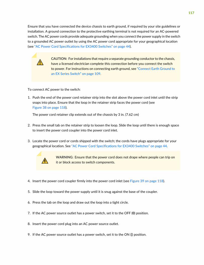
Ensure that you have connected the device chassis to earth ground, if required by your site guidelines orinstallation. A ground connection to the protective earthing terminal is not required for an AC-poweredswitch. The AC power cords provide adequate groundingwhen you connect the power supply in the switchto a grounded AC power outlet by using the AC power cord appropriate for your geographical location(see “AC Power Cord Specifications for EX3400 Switches” on page 44).
CAUTION: For installations that require a separate grounding conductor to the chassis,have a licensed electrician complete this connection before you connect the switchto power. For instructions on connecting earth ground, see “Connect Earth Ground toan EX Series Switch” on page 109.
To connect AC power to the switch:
1. Push the end of the power cord retainer strip into the slot above the power cord inlet until the stripsnaps into place. Ensure that the loop in the retainer strip faces the power cord (seeFigure 38 on page 118).
The power cord retainer clip extends out of the chassis by 3 in. (7.62 cm)
2. Press the small tab on the retainer strip to loosen the loop. Slide the loop until there is enough spaceto insert the power cord coupler into the power cord inlet.
3. Locate the power cord or cords shipped with the switch; the cords have plugs appropriate for yourgeographical location. See “AC Power Cord Specifications for EX3400 Switches” on page 44.
WARNING: Ensure that the power cord does not drape where people can trip onit or block access to switch components.
4. Insert the power cord coupler firmly into the power cord inlet (see Figure 39 on page 118).
5. Slide the loop toward the power supply until it is snug against the base of the coupler.
6. Press the tab on the loop and draw out the loop into a tight circle.
7. If the AC power source outlet has a power switch, set it to the OFF (0) position.
8. Insert the power cord plug into an AC power source outlet.
9. If the AC power source outlet has a power switch, set it to the ON (|) position.
117
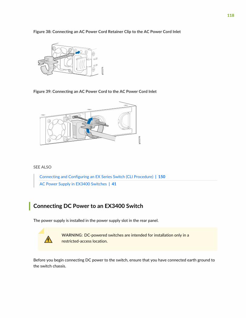
Figure 38: Connecting an AC Power Cord Retainer Clip to the AC Power Cord Inlet
Figure 39: Connecting an AC Power Cord to the AC Power Cord Inlet
SEE ALSO
Connecting and Configuring an EX Series Switch (CLI Procedure) | 150
AC Power Supply in EX3400 Switches | 41
Connecting DC Power to an EX3400 Switch
The power supply is installed in the power supply slot in the rear panel.
WARNING: DC-powered switches are intended for installation only in arestricted-access location.
Before you begin connecting DC power to the switch, ensure that you have connected earth ground tothe switch chassis.
118

CAUTION: To meet safety and electromagnetic interference (EMI) requirements andto ensure proper operation, you must connect the switch to earth ground before youconnect them to power. For installations that require a separate grounding conductorto the chassis, use the protective earthing terminal on the switch chassis to connectto the earth ground. For instructions on connecting earth ground, see “Connect EarthGround to an EX Series Switch” on page 109.
NOTE: Grounding is required for DC systems and recommended for AC systems.
Ensure that you have taken the necessary precautions to prevent electrostatic discharge (ESD) damage(see “Prevention of Electrostatic Discharge Damage” on page 276).
Install the power supply in the chassis. For instructions on installing a DC power supply in an EX3400switch, see “Installing a DC Power Supply in an EX3400 Switch” on page 202.
Ensure that you have the following parts and tools available:
• DC power source cables (14–16 AWG) (not provided)
• Wire pins (Molex 192120005) (not provided)
• Terminal connector (provided)
• Phillips (+) screwdriver, number 2
• Slotted (-) screwdriver
119

To connect DC power to the switch:
1. Ensure that the input circuit breaker is open so that the cable leads do not become active while youare connecting DC power.
NOTE: TheDC power inlet in the switch has two terminals labeled + and – and has a terminalto connect to earth ground. The DC power inlet has a clear plastic cover.
NOTE: The + terminal is referred to as +RTN and – terminal is referred to as –48 V in “DCPower Wiring SequenceWarning” on page 285 and “DC Power Electrical Safety Guidelines”on page 280.
2. Grasp the plastic cover in the middle, gently bend it outward, and pull it out. Save the cover.
3. Loosen the screws on the terminal connector by using the screwdriver.
4. Strip 0.25 inch (6.35 mm) of the insulator from one end of the power cable. Attach the two wires tothe wire pins.
5. Secure the wire pins to the appropriate terminals on the terminal connector by using the screws fromthe terminal connector (see Figure 40 on page 120).
Figure 40: Securing Wire Pins to the Terminals on the Terminal Connector
120
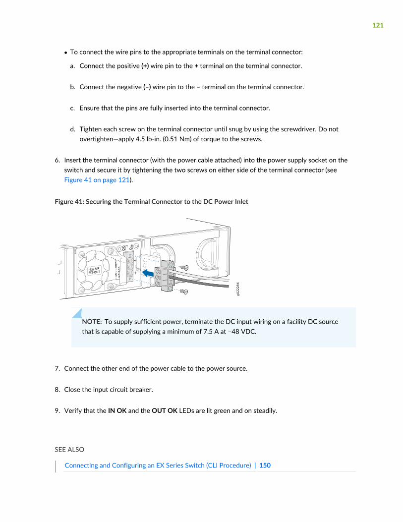
• To connect the wire pins to the appropriate terminals on the terminal connector:
a. Connect the positive (+) wire pin to the + terminal on the terminal connector.
b. Connect the negative (–) wire pin to the – terminal on the terminal connector.
c. Ensure that the pins are fully inserted into the terminal connector.
d. Tighten each screw on the terminal connector until snug by using the screwdriver. Do notovertighten—apply 4.5 lb-in. (0.51 Nm) of torque to the screws.
6. Insert the terminal connector (with the power cable attached) into the power supply socket on theswitch and secure it by tightening the two screws on either side of the terminal connector (seeFigure 41 on page 121).
Figure 41: Securing the Terminal Connector to the DC Power Inlet
NOTE: To supply sufficient power, terminate the DC input wiring on a facility DC sourcethat is capable of supplying a minimum of 7.5 A at –48 VDC.
7. Connect the other end of the power cable to the power source.
8. Close the input circuit breaker.
9. Verify that the IN OK and the OUT OK LEDs are lit green and on steadily.
SEE ALSO
Connecting and Configuring an EX Series Switch (CLI Procedure) | 150
121
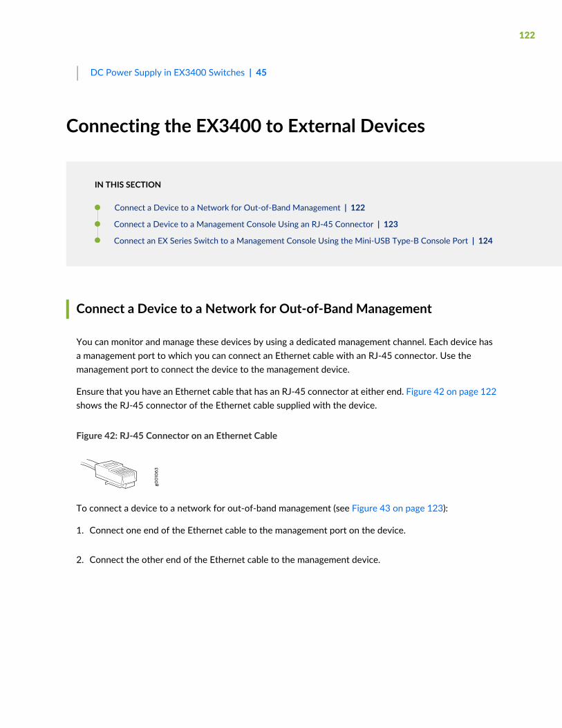
DC Power Supply in EX3400 Switches | 45
Connecting the EX3400 to External Devices
IN THIS SECTION
Connect a Device to a Network for Out-of-Band Management | 122
Connect a Device to a Management Console Using an RJ-45 Connector | 123
Connect an EX Series Switch to a Management Console Using the Mini-USB Type-B Console Port | 124
Connect a Device to a Network for Out-of-Band Management
You can monitor and manage these devices by using a dedicated management channel. Each device hasa management port to which you can connect an Ethernet cable with an RJ-45 connector. Use themanagement port to connect the device to the management device.
Ensure that you have an Ethernet cable that has an RJ-45 connector at either end. Figure 42 on page 122shows the RJ-45 connector of the Ethernet cable supplied with the device.
Figure 42: RJ-45 Connector on an Ethernet Cable
To connect a device to a network for out-of-band management (see Figure 43 on page 123):
1. Connect one end of the Ethernet cable to the management port on the device.
2. Connect the other end of the Ethernet cable to the management device.
122
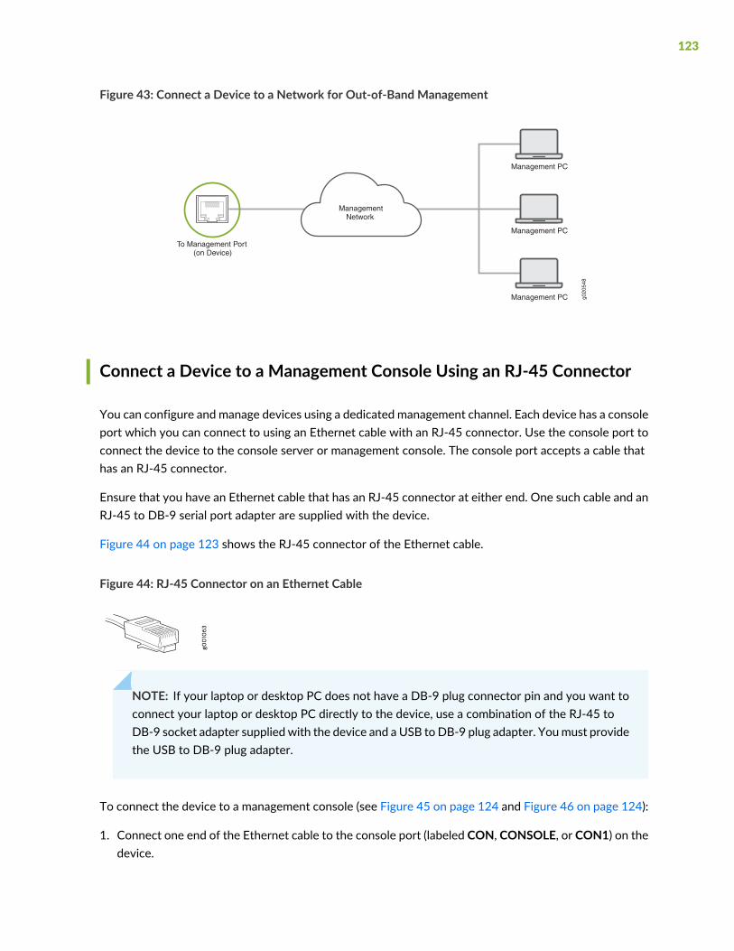
Figure 43: Connect a Device to a Network for Out-of-Band Management
g020
548
Management PC
Management PC
Management PC
ManagementNetwork
To Management Port(on Device)
Connect a Device to a Management Console Using an RJ-45 Connector
You can configure and manage devices using a dedicated management channel. Each device has a consoleport which you can connect to using an Ethernet cable with an RJ-45 connector. Use the console port toconnect the device to the console server or management console. The console port accepts a cable thathas an RJ-45 connector.
Ensure that you have an Ethernet cable that has an RJ-45 connector at either end. One such cable and anRJ-45 to DB-9 serial port adapter are supplied with the device.
Figure 44 on page 123 shows the RJ-45 connector of the Ethernet cable.
Figure 44: RJ-45 Connector on an Ethernet Cable
NOTE: If your laptop or desktop PC does not have a DB-9 plug connector pin and you want toconnect your laptop or desktop PC directly to the device, use a combination of the RJ-45 toDB-9 socket adapter supplied with the device and a USB toDB-9 plug adapter. Youmust providethe USB to DB-9 plug adapter.
To connect the device to a management console (see Figure 45 on page 124 and Figure 46 on page 124):
1. Connect one end of the Ethernet cable to the console port (labeled CON, CONSOLE, or CON1) on thedevice.
123
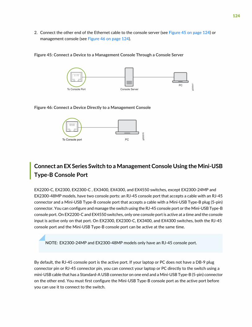
2. Connect the other end of the Ethernet cable to the console server (see Figure 45 on page 124) ormanagement console (see Figure 46 on page 124).
Figure 45: Connect a Device to a Management Console Through a Console Server
g020
547
PC
To Console Port Console Server
Figure 46: Connect a Device Directly to a Management Console
g020
570
To Console port PC
Connect an EXSeries Switch to aManagementConsoleUsing theMini-USBType-B Console Port
EX2200-C, EX2300, EX2300-C , EX3400, EX4300, and EX4550 switches, except EX2300-24MP andEX2300-48MP models, have two console ports: an RJ-45 console port that accepts a cable with an RJ-45connector and a Mini-USB Type-B console port that accepts a cable with a Mini-USB Type-B plug (5-pin)connector. You can configure andmanage the switch using the RJ-45 console port or theMini-USB Type-Bconsole port. On EX2200-C and EX4550 switches, only one console port is active at a time and the consoleinput is active only on that port. On EX2300, EX2300-C, EX3400, and EX4300 switches, both the RJ-45console port and the Mini-USB Type-B console port can be active at the same time.
NOTE: EX2300-24MP and EX2300-48MP models only have an RJ-45 console port.
By default, the RJ-45 console port is the active port. If your laptop or PC does not have a DB-9 plugconnector pin or RJ-45 connector pin, you can connect your laptop or PC directly to the switch using amini-USB cable that has a Standard-AUSB connector on one end and aMini-USB Type-B (5-pin) connectoron the other end. You must first configure the Mini-USB Type-B console port as the active port beforeyou can use it to connect to the switch.
124

This topic describes the procedure to connect EX2200-C, EX2300, EX2300-C, EX3400, EX4300, andEX4550 switches to the management console using the Mini-USB Type-B console port.
For information about configuring and managing an EX Series switch using the RJ-45 console port, see“Connect a Device to a Management Console Using an RJ-45 Connector” on page 123.
Before You Begin
Before you connect the switch using the Mini-USB Type-B console port:
• Ensure that the USB to Serial driver is installed on the host machine.
• Ensure that the HyperTerminal properties of the console server or laptop are set as follows:
• Baud rate—9600
• Flow control—None
• Data—8
• Parity—None
• Stop bits—1
• DCD state—Disregard
You will need the following parts and tools:
• One mini-USB cable with Standard-A and Mini-USB Type-B (5-pin) connectors (not provided)
To connect the switch to the console using the Mini-USB Type-B console port:
1. Connect the host machine to the device directly using the active console port or remotely using themanagement interface. To connect using the active console port, which is the RJ-45 console port bydefault, see “Connect a Device to a Management Console Using an RJ-45 Connector” on page 123.
2. Connect the Standard-A connector of the mini-USB cable to the host machine (PC or laptop).
3. Connect theMini-USB Type-B (5-pin) connector of themini-USB cable to theMini-USB Type-B consoleport (labeled CON) on the switch.
4. By default, the RJ-45 port is set as an active console port and the Mini-USB Type-B port is the passiveconsole port. Set the Mini-USB Type-B console port as the active console port using the port-typecommand. See Configuring the Console Port Type (CLI Procedure).
5. Reboot the switch. The boot log appears on the activated console.
125
After the connection is established, the Mini-USB Type-B becomes the active console port. The hostmachine connected to theMini-USB Type-B console port displays logmessages and you can control switchfunctionality through it. On EX2300, EX2300-C, EX3400, and EX4300 switches, both theMini-USB Type-Band RJ-45 console ports are now active. On EX2200-C and EX4550 switches, theMini-USB Type-B consoleport is active and the RJ-45 console port is passive.
Connecting the EX3400 to the Network
IN THIS SECTION
Install a Transceiver | 126
Connect a Fiber-Optic Cable | 129
Install a Transceiver
The transceivers for Juniper Networks devices are hot-removable and hot-insertable field-replaceableunits (FRUs): You can remove and replace them without powering off the device or disrupting the devicefunctions.
NOTE: After you insert a transceiver or after you change the media-type configuration, wait for6 seconds for the interface to display operational commands.
NOTE: We recommend that you use only optical transceivers and optical connectors purchasedfrom Juniper Networks with your Juniper Networks device.
CAUTION: If you face a problem running a Juniper Networks device that uses athird-party optic or cable, the Juniper Networks Technical Assistance Center (JTAC)can help you diagnose the source of the problem. Your JTACengineermight recommendthat you check the third-party optic or cable and potentially replace it with an equivalentJuniper Networks optic or cable that is qualified for the device.
126
Before you install a transceiver in a device, ensure that you have taken the necessary precautions for safehandling of lasers (see “Laser and LED Safety Guidelines and Warnings” on page 261).
Ensure that you have a rubber safety cap available to cover the transceiver.
Figure 47 on page 128 shows how to install a QSFP+ transceiver. The procedure is the same for all typesof transceivers except the QSFP28 and CFP transceivers.
To install a transceiver:
CAUTION: To prevent electrostatic discharge (ESD) damage to the transceiver, donot touch the connector pins at the end of the transceiver.
1. Wrap and fasten one end of the ESD wrist strap around your bare wrist, and connect the other end ofthe strap to the ESD point on the switch.
2. Remove the transceiver from its bag.
3. Check to seewhether the transceiver is coveredwith a rubber safety cap. If it is not, cover the transceiverwith a rubber safety cap.
WARNING: Donot leave a fiber-optic transceiver uncovered exceptwhen insertingor removing a cable. The rubber safety cap keeps the port clean and preventsaccidental exposure to laser light.
4. If the port in which you want to install the transceiver is covered with a dust cover, remove the dustcover and save it in case you need to cover the port later. If you are hot-swapping a transceiver, waitfor at least 10 seconds after removing the transceiver from the port before installing a new transceiver.
5. Using both hands, carefully place the transceiver in the empty port. The connectors must face thechassis.
CAUTION: Before you slide the transceiver into the port, ensure that the transceiveris aligned correctly. Misalignment might cause the pins to bend, making thetransceiver unusable.
6. Slide the transceiver in gently until it is fully seated. If you are installing a CFP transceiver, tighten thecaptive screws on the transceiver by using your fingers.
127
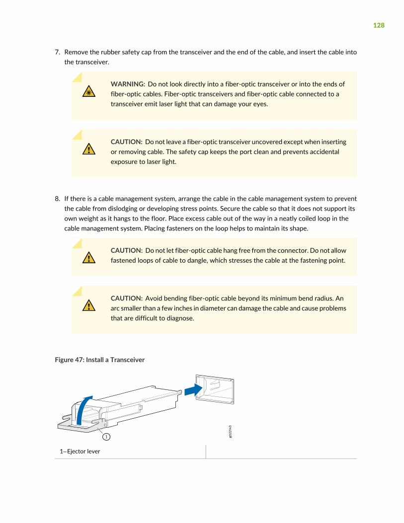
7. Remove the rubber safety cap from the transceiver and the end of the cable, and insert the cable intothe transceiver.
WARNING: Do not look directly into a fiber-optic transceiver or into the ends offiber-optic cables. Fiber-optic transceivers and fiber-optic cable connected to atransceiver emit laser light that can damage your eyes.
CAUTION: Do not leave a fiber-optic transceiver uncovered except when insertingor removing cable. The safety cap keeps the port clean and prevents accidentalexposure to laser light.
8. If there is a cable management system, arrange the cable in the cable management system to preventthe cable from dislodging or developing stress points. Secure the cable so that it does not support itsown weight as it hangs to the floor. Place excess cable out of the way in a neatly coiled loop in thecable management system. Placing fasteners on the loop helps to maintain its shape.
CAUTION: Do not let fiber-optic cable hang free from the connector. Do not allowfastened loops of cable to dangle, which stresses the cable at the fastening point.
CAUTION: Avoid bending fiber-optic cable beyond its minimum bend radius. Anarc smaller than a few inches in diameter can damage the cable and cause problemsthat are difficult to diagnose.
Figure 47: Install a Transceiver
1—Ejector lever
128
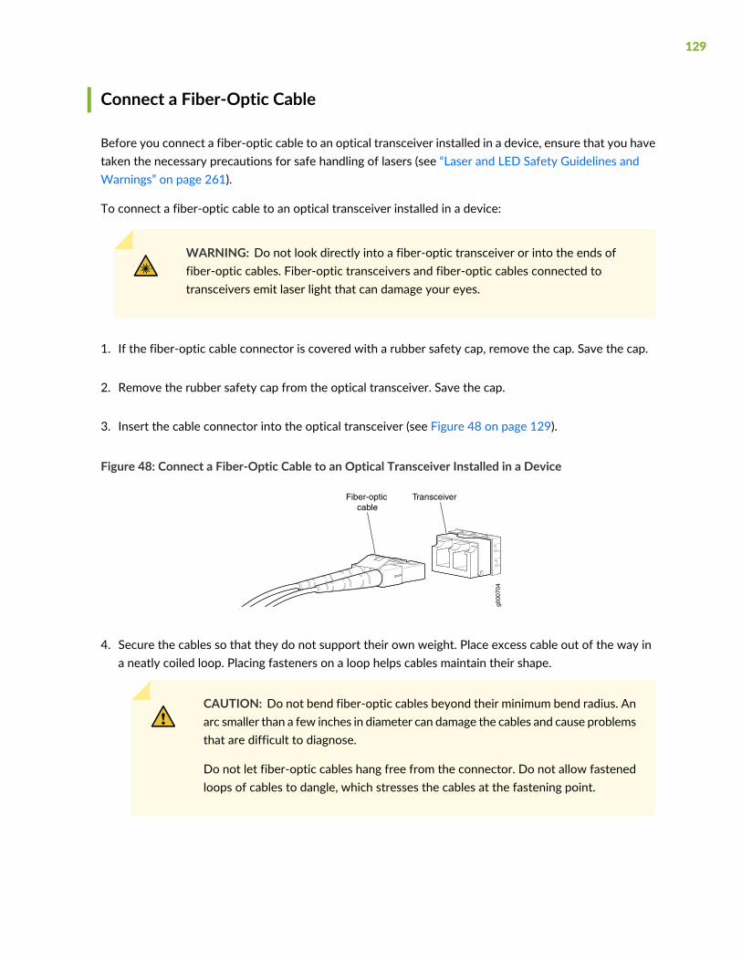
Connect a Fiber-Optic Cable
Before you connect a fiber-optic cable to an optical transceiver installed in a device, ensure that you havetaken the necessary precautions for safe handling of lasers (see “Laser and LED Safety Guidelines andWarnings” on page 261).
To connect a fiber-optic cable to an optical transceiver installed in a device:
WARNING: Do not look directly into a fiber-optic transceiver or into the ends offiber-optic cables. Fiber-optic transceivers and fiber-optic cables connected totransceivers emit laser light that can damage your eyes.
1. If the fiber-optic cable connector is covered with a rubber safety cap, remove the cap. Save the cap.
2. Remove the rubber safety cap from the optical transceiver. Save the cap.
3. Insert the cable connector into the optical transceiver (see Figure 48 on page 129).
Figure 48: Connect a Fiber-Optic Cable to an Optical Transceiver Installed in a Device
g000
704
TransceiverFiber-opticcable
4. Secure the cables so that they do not support their own weight. Place excess cable out of the way ina neatly coiled loop. Placing fasteners on a loop helps cables maintain their shape.
CAUTION: Do not bend fiber-optic cables beyond their minimum bend radius. Anarc smaller than a few inches in diameter can damage the cables and cause problemsthat are difficult to diagnose.
Do not let fiber-optic cables hang free from the connector. Do not allow fastenedloops of cables to dangle, which stresses the cables at the fastening point.
129
Configuring Junos OS on the EX3400
IN THIS SECTION
EX3400 Switch Default Configuration | 130
Connecting and Configuring an EX Series Switch (CLI Procedure) | 150
Connecting and Configuring an EX Series Switch (J-Web Procedure) | 154
Reverting to the Default Factory Configuration for the EX Series Switch | 158
EX3400 Switch Default Configuration
Each EX Series switch is programmed with a factory-default configuration that contains the values set foreach configuration parameter when a switch is shipped.
The EX3400 switch default configuration:
• Sets Ethernet switching and storm control on all interfaces
• Sets Power over Ethernet (PoE) on all RJ-45 ports of models that provide PoE
• Enables the following protocols:
• Internet Group Management Protocol (IGMP) snooping
• Rapid Spanning Tree Protocol (RSTP)
• Link Layer Discovery Protocol (LLDP)
• Link Layer Discovery Protocol Media Endpoint Discovery (LLDP-MED)
When you commit changes to the configuration, a new configuration file is created that becomes theactive configuration. You can always revert to the factory-default configuration. See “Reverting to theDefault Factory Configuration for the EX Series Switch” on page 158.
130
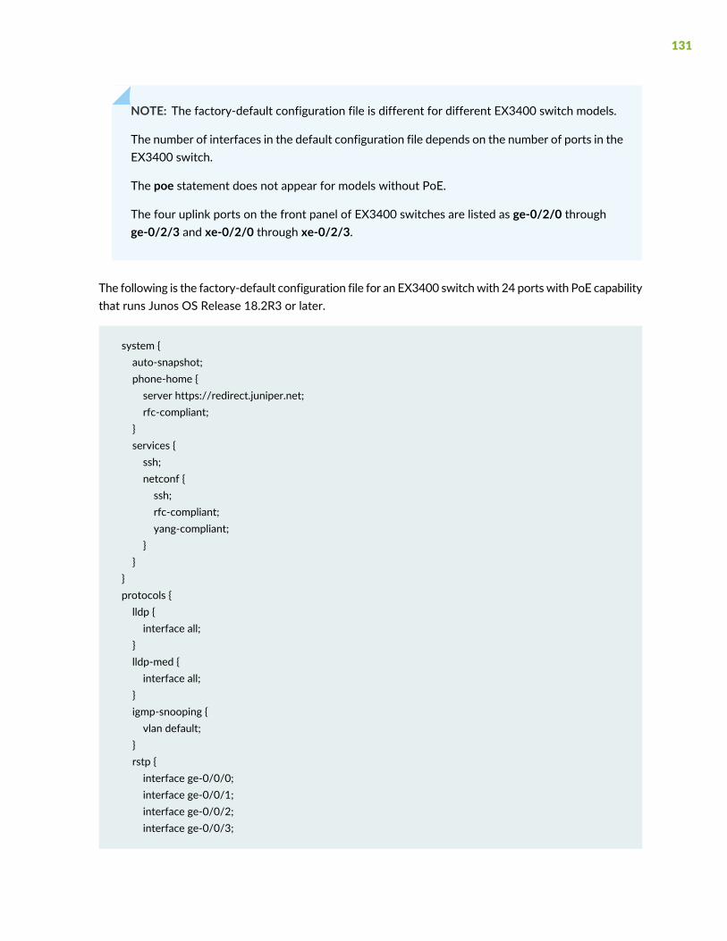
NOTE: The factory-default configuration file is different for different EX3400 switch models.
The number of interfaces in the default configuration file depends on the number of ports in theEX3400 switch.
The poe statement does not appear for models without PoE.
The four uplink ports on the front panel of EX3400 switches are listed as ge-0/2/0 throughge-0/2/3 and xe-0/2/0 through xe-0/2/3.
The following is the factory-default configuration file for an EX3400 switchwith 24 portswith PoE capabilitythat runs Junos OS Release 18.2R3 or later.
system {auto-snapshot;phone-home {server https://redirect.juniper.net;rfc-compliant;
}services {ssh;netconf {ssh;rfc-compliant;yang-compliant;
}}
}protocols {lldp {interface all;
}lldp-med {interface all;
}igmp-snooping {vlan default;
}rstp {interface ge-0/0/0;interface ge-0/0/1;interface ge-0/0/2;interface ge-0/0/3;
131

interface ge-0/0/4;interface ge-0/0/5;interface ge-0/0/6;interface ge-0/0/7;interface ge-0/0/8;interface ge-0/0/9;interface ge-0/0/10;interface ge-0/0/11;interface ge-0/0/12;interface ge-0/0/13;interface ge-0/0/14;interface ge-0/0/15;interface ge-0/0/16;interface ge-0/0/17;interface ge-0/0/18;interface ge-0/0/19;interface ge-0/0/20;interface ge-0/0/21;interface ge-0/0/22;interface ge-0/0/23;interface xe-0/2/0;interface xe-0/2/1;interface xe-0/2/2;interface xe-0/2/3;interface ge-0/2/0;interface ge-0/2/1;interface ge-0/2/2;interface ge-0/2/3;
}}forwarding-options {storm-control-profiles default {all;
}}poe {interface all;
}interfaces {## For phone-home connectivity to PHS enable dhcp on vme and irb.vme {unit 0 {family inet {dhcp;
132
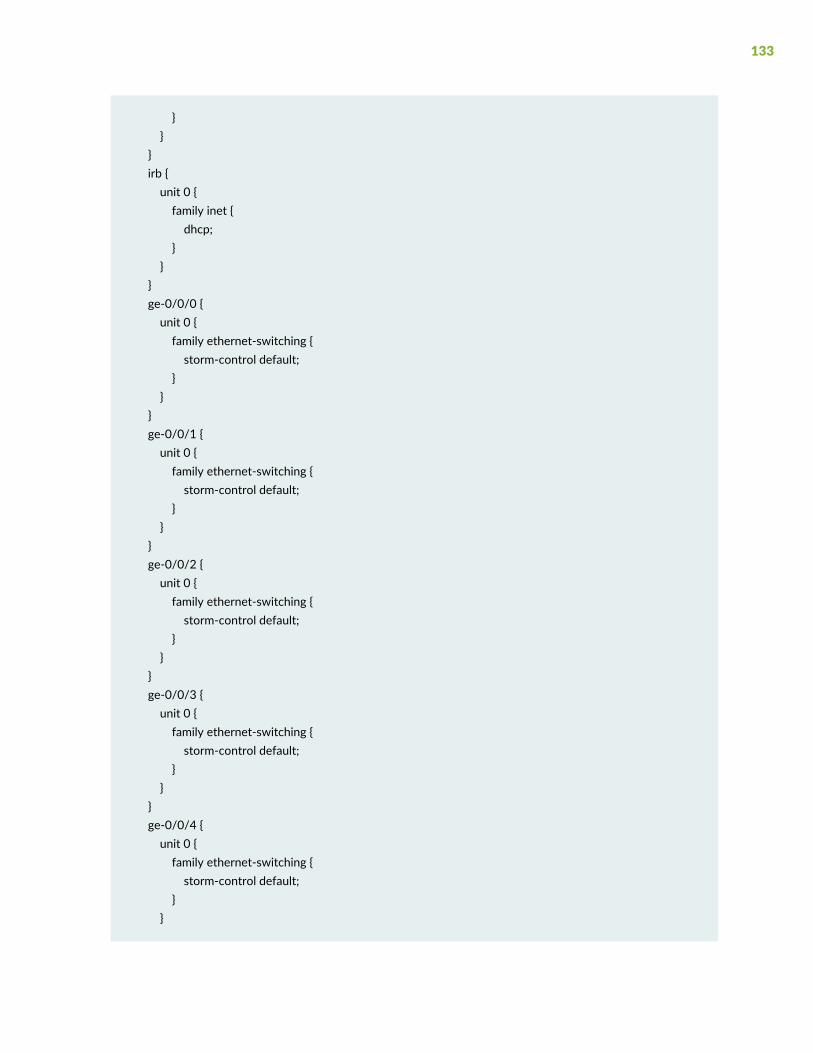
}}
}irb {unit 0 {family inet {dhcp;
}}
}ge-0/0/0 {unit 0 {family ethernet-switching {storm-control default;
}}
}ge-0/0/1 {unit 0 {family ethernet-switching {storm-control default;
}}
}ge-0/0/2 {unit 0 {family ethernet-switching {storm-control default;
}}
}ge-0/0/3 {unit 0 {family ethernet-switching {storm-control default;
}}
}ge-0/0/4 {unit 0 {family ethernet-switching {storm-control default;
}}
133

}ge-0/0/5 {unit 0 {family ethernet-switching {storm-control default;
}}
}ge-0/0/6 {unit 0 {family ethernet-switching {storm-control default;
}}
}ge-0/0/7 {unit 0 {family ethernet-switching {storm-control default;
}}
}ge-0/0/8 {unit 0 {family ethernet-switching {storm-control default;
}}
}ge-0/0/9 {unit 0 {family ethernet-switching {storm-control default;
}}
}ge-0/0/10 {unit 0 {family ethernet-switching {storm-control default;
}}
}ge-0/0/11 {
134

unit 0 {family ethernet-switching {storm-control default;
}}
}ge-0/0/12 {unit 0 {family ethernet-switching {storm-control default;
}}
}ge-0/0/13 {unit 0 {family ethernet-switching {storm-control default;
}}
}ge-0/0/14 {unit 0 {family ethernet-switching {storm-control default;
}}
}ge-0/0/15 {unit 0 {family ethernet-switching {storm-control default;
}}
}ge-0/0/16 {unit 0 {family ethernet-switching {storm-control default;
}}
}ge-0/0/17 {unit 0 {family ethernet-switching {
135

storm-control default;}
}}ge-0/0/18 {unit 0 {family ethernet-switching {storm-control default;
}}
}ge-0/0/19 {unit 0 {family ethernet-switching {storm-control default;
}}
}ge-0/0/20 {unit 0 {family ethernet-switching {storm-control default;
}}
}ge-0/0/21 {unit 0 {family ethernet-switching {storm-control default;
}}
}ge-0/0/22 {unit 0 {family ethernet-switching {storm-control default;
}}
}ge-0/0/23 {unit 0 {family ethernet-switching {storm-control default;
}
136
}}xe-0/2/0 {unit 0 {family ethernet-switching {storm-control default;
}}
}xe-0/2/1 {unit 0 {family ethernet-switching {storm-control default;
}}
}xe-0/2/2 {unit 0 {family ethernet-switching {storm-control default;
}}
}xe-0/2/3 {unit 0 {family ethernet-switching {storm-control default;
}}
}ge-0/2/0 {unit 0 {family ethernet-switching {storm-control default;
}}
}ge-0/2/1 {unit 0 {family ethernet-switching {storm-control default;
}}
}
137
ge-0/2/2 {unit 0 {family ethernet-switching {storm-control default;
}}
}ge-0/2/3 {unit 0 {family ethernet-switching {storm-control default;
}}
}}groups {junos-defaults {protocols {igmp {interface me0.0 {disable;
}interface vme.0 {disable;
}}
}}
}system {commit {factory-settings {reset-chassis-lcd-menu;reset-virtual-chassis-configuration;
}}
}chassis {redundancy {graceful-switchover;
}}vlans {default {
138

vlan-id 1;l3-interface irb.0;
}}
The following is the factory-default configuration file for an EX3400 switchwith 48 portswith PoE capabilitythat runs a version of Junos OS release earlier than 18.2R3.
system {auto-snapshot;syslog {user * {any emergency;
}file messages {any notice;authorization info;
}file interactive-commands {interactive-commands any;
}}commit {factory-settings {reset-virtual-chassis-configuration;reset-chassis-lcd-menu;
}}
}interfaces {ge-0/0/0 {unit 0 {family ethernet-switching {storm-control default;
}}
}ge-0/0/1 {unit 0 {family ethernet-switching {storm-control default;
}}
}
139

ge-0/0/2 {unit 0 {family ethernet-switching {storm-control default;
}}
}ge-0/0/3 {unit 0 {family ethernet-switching {storm-control default;
}}
}ge-0/0/4 {unit 0 {family ethernet-switching {storm-control default;
}}
}ge-0/0/5 {unit 0 {family ethernet-switching {storm-control default;
}}
}ge-0/0/6 {unit 0 {family ethernet-switching {storm-control default;
}}
}ge-0/0/7 {unit 0 {family ethernet-switching {storm-control default;
}}
}ge-0/0/8 {unit 0 {
140
family ethernet-switching {storm-control default;
}}
}ge-0/0/9 {unit 0 {family ethernet-switching {storm-control default;
}}
}ge-0/0/10 {unit 0 {family ethernet-switching {storm-control default;
}}
}ge-0/0/11 {unit 0 {family ethernet-switching {storm-control default;
}}
}ge-0/0/12 {unit 0 {family ethernet-switching {storm-control default;
}}
}ge-0/0/13 {unit 0 {family ethernet-switching {storm-control default;
}}
}ge-0/0/14 {unit 0 {family ethernet-switching {storm-control default;
141
}}
}ge-0/0/15 {unit 0 {family ethernet-switching {storm-control default;
}}
}ge-0/0/16 {unit 0 {family ethernet-switching {storm-control default;
}}
}ge-0/0/17 {unit 0 {family ethernet-switching {storm-control default;
}}
}ge-0/0/18 {unit 0 {family ethernet-switching {storm-control default;
}}
}ge-0/0/19 {unit 0 {family ethernet-switching {storm-control default;
}}
}ge-0/0/20 {unit 0 {family ethernet-switching {storm-control default;
}}
142
}ge-0/0/21 {unit 0 {family ethernet-switching {storm-control default;
}}
}ge-0/0/22 {unit 0 {family ethernet-switching {storm-control default;
}}
}ge-0/0/23 {unit 0 {family ethernet-switching {storm-control default;
}}
}ge-0/0/24 {unit 0 {family ethernet-switching {storm-control default;
}}
}ge-0/0/25 {unit 0 {family ethernet-switching {storm-control default;
}}
}ge-0/0/26 {unit 0 {family ethernet-switching {storm-control default;
}}
}ge-0/0/27 {
143

unit 0 {family ethernet-switching {storm-control default;
}}
}ge-0/0/28 {unit 0 {family ethernet-switching {storm-control default;
}}
}ge-0/0/29 {unit 0 {family ethernet-switching {storm-control default;
}}
}ge-0/0/30 {unit 0 {family ethernet-switching {storm-control default;
}}
}ge-0/0/31 {unit 0 {family ethernet-switching {storm-control default;
}}
}ge-0/0/32 {unit 0 {family ethernet-switching {storm-control default;
}}
}ge-0/0/33 {unit 0 {family ethernet-switching {
144
storm-control default;}
}}ge-0/0/34 {unit 0 {family ethernet-switching {storm-control default;
}}
}ge-0/0/35 {unit 0 {family ethernet-switching {storm-control default;
}}
}ge-0/0/36 {unit 0 {family ethernet-switching {storm-control default;
}}
}ge-0/0/37 {unit 0 {family ethernet-switching {storm-control default;
}}
}ge-0/0/38 {unit 0 {family ethernet-switching {storm-control default;
}}
}ge-0/0/39 {unit 0 {family ethernet-switching {storm-control default;
}
145
}}ge-0/0/40 {unit 0 {family ethernet-switching {storm-control default;
}}
}ge-0/0/41 {unit 0 {family ethernet-switching {storm-control default;
}}
}ge-0/0/42 {unit 0 {family ethernet-switching {storm-control default;
}}
}ge-0/0/43 {unit 0 {family ethernet-switching {storm-control default;
}}
}ge-0/0/44 {unit 0 {family ethernet-switching {storm-control default;
}}
}ge-0/0/45 {unit 0 {family ethernet-switching {storm-control default;
}}
}
146
ge-0/0/46 {unit 0 {family ethernet-switching {storm-control default;
}}
}ge-0/0/47 {unit 0 {family ethernet-switching {storm-control default;
}}
}ge-0/2/0 {unit 0 {family ethernet-switching {storm-control default;
}}
}xe-0/2/0 {unit 0 {family ethernet-switching {storm-control default;
}}
}ge-0/2/1 {unit 0 {family ethernet-switching {storm-control default;
}}
}xe-0/2/1 {unit 0 {family ethernet-switching {storm-control default;
}}
}ge-0/2/2 {unit 0 {
147
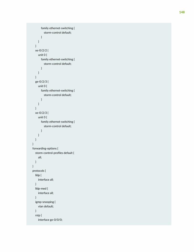
family ethernet-switching {storm-control default;
}}
}xe-0/2/2 {unit 0 {family ethernet-switching {storm-control default;
}}
}ge-0/2/3 {unit 0 {family ethernet-switching {storm-control default;
}}
}xe-0/2/3 {unit 0 {family ethernet-switching {storm-control default;
}}
}}forwarding-options {storm-control-profiles default {all;
}}protocols {lldp {interface all;
}lldp-med {interface all;
}igmp-snooping {vlan default;
}rstp {interface ge-0/0/0;
148

interface ge-0/0/1;interface ge-0/0/2;interface ge-0/0/3;interface ge-0/0/4;interface ge-0/0/5;interface ge-0/0/6;interface ge-0/0/7;interface ge-0/0/8;interface ge-0/0/9;interface ge-0/0/10;interface ge-0/0/11;interface ge-0/0/12;interface ge-0/0/13;interface ge-0/0/14;interface ge-0/0/15;interface ge-0/0/16;interface ge-0/0/17;interface ge-0/0/18;interface ge-0/0/19;interface ge-0/0/20;interface ge-0/0/21;interface ge-0/0/22;interface ge-0/0/23;interface ge-0/0/24;interface ge-0/0/25;interface ge-0/0/26;interface ge-0/0/27;interface ge-0/0/28;interface ge-0/0/29;interface ge-0/0/30;interface ge-0/0/31;interface ge-0/0/32;interface ge-0/0/33;interface ge-0/0/34;interface ge-0/0/35;interface ge-0/0/36;interface ge-0/0/37;interface ge-0/0/38;interface ge-0/0/39;interface ge-0/0/40;interface ge-0/0/41;interface ge-0/0/42;interface ge-0/0/43;interface ge-0/0/44;
149
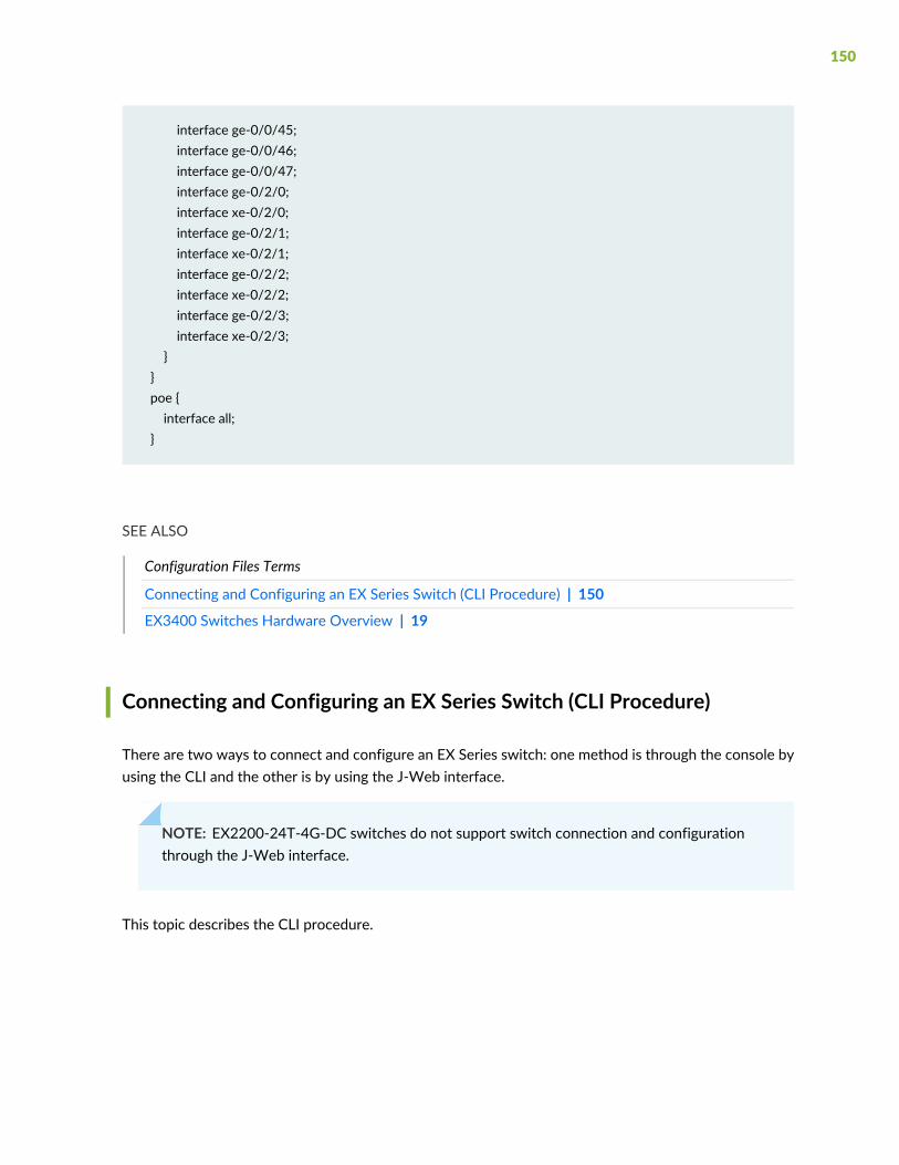
interface ge-0/0/45;interface ge-0/0/46;interface ge-0/0/47;interface ge-0/2/0;interface xe-0/2/0;interface ge-0/2/1;interface xe-0/2/1;interface ge-0/2/2;interface xe-0/2/2;interface ge-0/2/3;interface xe-0/2/3;
}}poe {interface all;
}
SEE ALSO
Configuration Files Terms
Connecting and Configuring an EX Series Switch (CLI Procedure) | 150
EX3400 Switches Hardware Overview | 19
Connecting and Configuring an EX Series Switch (CLI Procedure)
There are two ways to connect and configure an EX Series switch: one method is through the console byusing the CLI and the other is by using the J-Web interface.
NOTE: EX2200-24T-4G-DC switches do not support switch connection and configurationthrough the J-Web interface.
This topic describes the CLI procedure.
150

NOTE: To run the ezsetup script, the switch must have the factory-default configuration as theactive configuration. If you have configured anything on the switch and want to run ezsetup,revert to the factory-default configuration. See “Reverting to the Default Factory Configurationfor the EX Series Switch” on page 158.
Using the CLI, set the following parameter values in the console server or PC:
• Baud rate—9600
• Flow control—None
• Data—8
• Parity—None
• Stop bits—1
• DCD state—Disregard
151

To connect and configure the switch from the console by using the CLI:
1. Connect the console port to a laptop or PC by using the RJ-45 to DB-9 serial port adapter. An Ethernetcable that has an RJ-45 connector at either end and an RJ-45 to DB-9 serial port adapter are suppliedwith the switch. If your laptop doesn't have a serial port, use a serial to USB adapter.
For the location of the console port on different EX Series switches:
• See EX2200 Switches Hardware Overview.
• See EX2300 Switches Hardware Overview.
• See Rear Panel of an EX3200 Switch.
• See Rear Panel of an EX3300 Switch.
• See “Rear Panel of an EX3400 Switch” on page 30.
• See Rear Panel of an EX4200 Switch.
• See EX4300 Switches Hardware Overview
• See Front Panel of an EX4500 Switch.
• See EX4550 Switches Hardware Overview
• See Switch Fabric and Routing Engine (SRE) Module in an EX6200 Switch.
• See Switch Fabric and Routing Engine (SRE) Module in an EX8208 Switch.
• See Routing Engine (RE) Module in an EX8216 Switch.
NOTE: In EX2200-C, EX2300, EX3400, EX4300, and EX4550 switches, you can also use theMini-USB Type-B console port to connect to a laptop or PC. See “Connect an EX Series Switchto a Management Console Using the Mini-USB Type-B Console Port” on page 124.
2. At the Junos OS shell prompt root%, type ezsetup.
3. Enter the hostname. This is optional.
4. Enter the root password you want to use for the device. Reenter the root password when prompted.
152
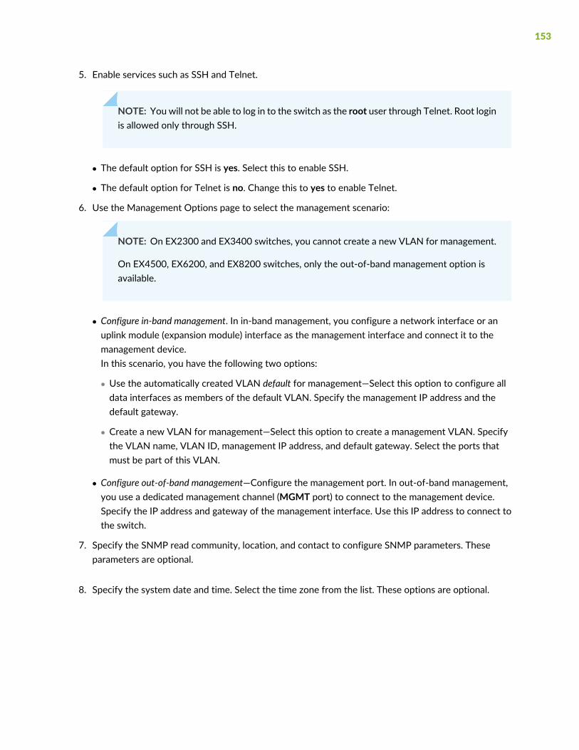
5. Enable services such as SSH and Telnet.
NOTE: You will not be able to log in to the switch as the root user through Telnet. Root loginis allowed only through SSH.
• The default option for SSH is yes. Select this to enable SSH.
• The default option for Telnet is no. Change this to yes to enable Telnet.
6. Use the Management Options page to select the management scenario:
NOTE: On EX2300 and EX3400 switches, you cannot create a new VLAN for management.
On EX4500, EX6200, and EX8200 switches, only the out-of-band management option isavailable.
• Configure in-band management. In in-band management, you configure a network interface or anuplink module (expansion module) interface as the management interface and connect it to themanagement device.In this scenario, you have the following two options:
• Use the automatically created VLAN default for management—Select this option to configure alldata interfaces as members of the default VLAN. Specify the management IP address and thedefault gateway.
• Create a new VLAN for management—Select this option to create a management VLAN. Specifythe VLAN name, VLAN ID, management IP address, and default gateway. Select the ports thatmust be part of this VLAN.
• Configure out-of-band management—Configure the management port. In out-of-band management,you use a dedicated management channel (MGMT port) to connect to the management device.Specify the IP address and gateway of the management interface. Use this IP address to connect tothe switch.
7. Specify the SNMP read community, location, and contact to configure SNMP parameters. Theseparameters are optional.
8. Specify the system date and time. Select the time zone from the list. These options are optional.
153
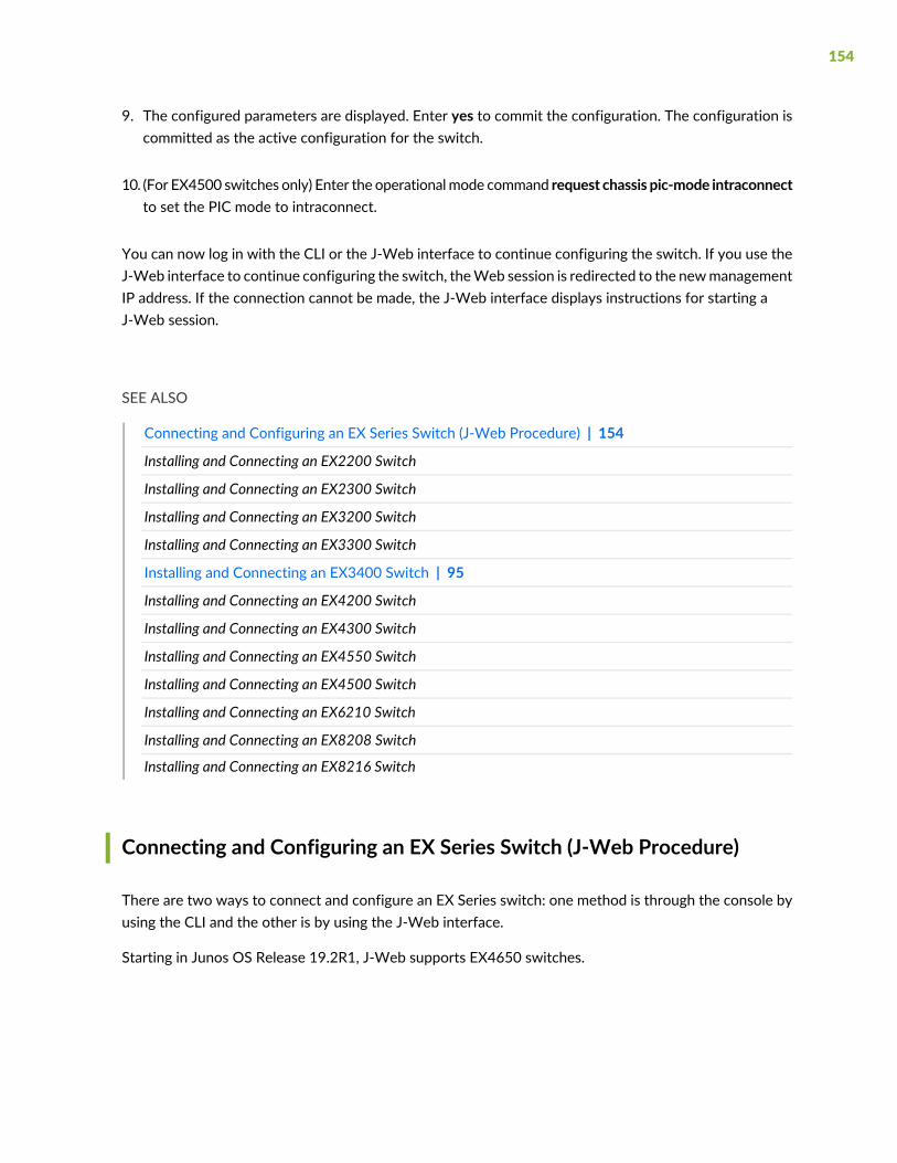
9. The configured parameters are displayed. Enter yes to commit the configuration. The configuration iscommitted as the active configuration for the switch.
10. (For EX4500 switches only) Enter the operationalmode command request chassis pic-mode intraconnectto set the PIC mode to intraconnect.
You can now log in with the CLI or the J-Web interface to continue configuring the switch. If you use theJ-Web interface to continue configuring the switch, theWeb session is redirected to the newmanagementIP address. If the connection cannot be made, the J-Web interface displays instructions for starting aJ-Web session.
SEE ALSO
Connecting and Configuring an EX Series Switch (J-Web Procedure) | 154
Installing and Connecting an EX2200 Switch
Installing and Connecting an EX2300 Switch
Installing and Connecting an EX3200 Switch
Installing and Connecting an EX3300 Switch
Installing and Connecting an EX3400 Switch | 95
Installing and Connecting an EX4200 Switch
Installing and Connecting an EX4300 Switch
Installing and Connecting an EX4550 Switch
Installing and Connecting an EX4500 Switch
Installing and Connecting an EX6210 Switch
Installing and Connecting an EX8208 Switch
Installing and Connecting an EX8216 Switch
Connecting and Configuring an EX Series Switch (J-Web Procedure)
There are two ways to connect and configure an EX Series switch: one method is through the console byusing the CLI and the other is by using the J-Web interface.
Starting in Junos OS Release 19.2R1, J-Web supports EX4650 switches.
154
NOTE: You cannot connect to and perform initial configuration of EX2200-24T-4G-DC,EX4300-48MP, EX4300-48MP-S switches, and EX4600 switches using EZSetup procedure fromthe J-Web interface. For EX2200-24T-4G-DC switches, you must use EZSetup from the switchconsole. For EX4300-48MP, EX4300-48MP-S, and EX4600 switches, you must use the CLIprocedure through the switch console.
This topic describes the J-Web procedure.
NOTE: Before you begin the configuration, enable a DHCP client on the management PC thatyou will connect to the switch so that the PC can obtain an IP address dynamically.
NOTE: Read the following steps before you begin the configuration. You must complete theinitial configuration by using EZSetup within 10 minutes. The switch exits EZSetup after 10minutes and reverts to the factory default configuration, and the PC loses connectivity to theswitch.
• EX2200 and EX2200-C switch—The LEDs on the network ports on the front panel blink whenthe switch is in the initial setup mode.
• EX3200, EX3300, EX4200, EX4300 switches except EX4300-48MP and EX4300-48MP-Sswitches, EX4500, EX4550, EX6200, or EX8200 switch—The LCDpanel displays a count-downtimer when the switch is in initial setup mode.
NOTE: There is no LCD panel on EX4300-48MP and EX4300-48MP-S switches.
155

To connect and configure the switch by using the J-Web interface:
1. Transition the switch into initial setup mode:
• EX2200 and EX2200-C switch—Press the mode button located on the lower right corner of the frontpanel for 10 seconds.
• EX3200, EX3300, EX4200, EX4300 switches except EX4300-48MP and EX4300-48MP-S switches,EX4500, EX4550, EX6200, or EX8200 switch—Use theMenu and Enter buttons located to the rightof the LCD panel (see Figure 49 on page 156 or Figure 50 on page 156):
Figure 49: LCD Panel in an EX3200, EX4200, EX4500, EX4550, or EX8200 Switch
Figure 50: LCD Panel in an EX4300 Switches Except EX4300-48MP and EX4300-48MP-S Switches
3—1— LCD panel Menu buttonLCD panel
4—2— Chassis status LEDsLCD panel Enter button
1. Press theMenu button until you seeMAINTENANCE MENU. Then press the Enter button.
2. PressMenu until you see ENTER EZSetup. Then press Enter.
If EZSetup does not appear as an option in the menu, select Factory Default to return the switchto the factory default configuration. EZSetup is displayed in the menu of standalone switchesonly when a switch is set to the factory default configuration.
3. Press Enter to confirm setup and continue with EZSetup.
2. Connect the Ethernet cable from the Ethernet port on the PC to the switch.
• EX2200, EX3200, or EX4200 switch—Connect the cable to port 0 (ge-0/0/0) on the front panel ofthe switch.
• EX3300 switch—Connect the cable to the port labeledMGMT on the rear panel of the switch.
• EX4300 switches except EX4300-48MP and EX4300-48MP-S switches—Connect the cable to theport labeledMGMT on the rear panel of the switch.
156

• EX4500 or EX4550 switch—Connect the cable to the port labeledMGMT on the front panel (LCDpanel side) of the switch.
• EX4650 switches—Connect the cable to the port labeled CON on the rear panel of the switch.
• EX6200 switch—Connect the cable to one of the ports labeledMGMT on the Switch Fabric andRouting Engine (SRE) module in slot 4 or 5 in an EX6210 switch.
• EX8200 switch—Connect the cable to the port labeledMGMT on the Switch Fabric and RoutingEngine (SRE) module in slot SRE0 in an EX8208 switch or on the Routing Engine (RE) module in slotRE0 in an EX8216 switch.
These ports are configured as the DHCP server with the default IP address, 192.168.1.1. The switchcan assign an IP address to the management PC in the IP address range 192.168.1.2 through192.168.1.253.
3. From the PC, open a Web browser, type http://192.168.1.1 in the address field, and press Enter.
4. On the J-Web login page, type root as the username, leave the password field blank, and click Login.
5. On the Introduction page, click Next.
6. On the Basic Settings page, modify the hostname, the root password, and date and time settings:
• Enter the hostname. This is optional.
• Enter a password and reenter the password.
• Specify the time zone.
• Synchronize the date and time settings of the switch with the management PC or set them manuallyby selecting the appropriate option button. This is optional.
Click Next.
7. Use the Management Options page to select the management scenario:
NOTE: On EX2300 and EX3400 switches, you cannot create a new VLAN for management.
On EX4500, EX6210, and EX8200 switches, only the out-of-band management option isavailable.
• Configure in-band management. In in-band management, you configure a network interface or anuplink module (expansion module) interface as the management interface and connect it to themanagement device.In this scenario, you have the following two options:
157
• Use the automatically created VLAN default for management—Select this option to configure alldata interfaces as members of the default VLAN. Specify the management IP address and thedefault gateway.
• Create a new VLAN for management—Select this option to create a management VLAN. Specifythe VLAN name, VLAN ID, management IP address, and default gateway. Select the ports thatmust be part of this VLAN.
• Configure out-of-band management—Configure the management port. In out-of-band management,you use a dedicated management channel (MGMT port) to connect to the management device.Specify the IP address and gateway of the management interface. Use this IP address to connect tothe switch.
8. Click Next.
9. On the Manage Access page, you can select options to enable Telnet, SSH, and SNMP services. ForSNMP, you can configure the read community, location, and contact.
10.Click Next. The Summary screen displays the configured settings.
11.Click Finish. The configuration is committed as the active switch configuration.
NOTE: After the configuration is committed, the connectivity between the PC and the switchmight be lost. To renew the connection, release and renew the IP address by executing theappropriate commands on the management PC or by removing and reinserting the Ethernetcable.
12. (For EX4500 switches only) In the CLI, enter the request chassis pic-mode intraconnect operationalmode command to set the PIC mode to intraconnect.
You can now log in by using the CLI or the J-Web interface to continue configuring the switch.
If you use the J-Web interface to continue configuring the switch, the Web session is redirected to thenewmanagement IP address. If the connection cannot be made, the J-Web interface displays instructionsfor starting a J-Web session.
Reverting to the Default Factory Configuration for the EX Series Switch
With EX Series switches, if for any reason the current active configuration fails, you can revert to thefactory-default configuration.
158
You can also roll back to a previous configuration, as described in Rolling Back Junos OS ConfigurationChanges, or revert to the rescue configuration, as described in Reverting to the Rescue Configuration for theEX Series Switch.
TIP: If you have lost the root password, it is not necessary to revert to the factory-defaultconfiguration to reset it. See Recovering the Root Password on Switches.
The factory-default configuration contains the basic configuration settings for the switch. This is the firstconfiguration of the switch and it is loaded when the switch is first powered on. For the factory-defaultconfiguration file for your switch, see the hardware documentation for your switch.
TIP: You can run the EZsetup script to complete the initial configuration of the switch afterreverting to the factory-default configuration. (The EZsetup script is available only on fixedconfiguration switches, it is not available on modular switches.) For information on completingthe initial configuration using either the CLI or the J-Web interface, see “Connecting andConfiguring an EX Series Switch (CLI Procedure)” on page 150 or “Connecting and Configuringan EX Series Switch (J-Web Procedure)” on page 154.
You can revert to the factory-default configuration by using theMenu button to the right of the LCD panelon switches with LCD panel or by using the request system zeroize operational command or the loadfactory-default configuration command. (If your switch model does not have an LCD panel, use thesecommands.) You can also use the load factory-default command to revert to the factory-defaultconfiguration file that contains all default settings except the root password setting, which is retained.
These procedures are described in the following sections:
Reverting to the EX Series Switch Factory-Default Configuration Using the request system zeroizeCommand | 159
Reverting to the EX Series Switch Factory-Default Configuration Using the load factory-defaultCommand | 160
Reverting to the Factory-Default Configuration Using the EX Series Switch LCD Panel | 161
Reverting to the Factory-Default Configuration Using the Factory Reset/Mode button on EX2300,EX3400, and EX4300-48MP Switches | 162
Reverting to the EX Series Switch Factory-Default Configuration Using the request systemzeroize Command
The request system zeroize command is a standard Junos OS operational mode command that removesall configuration information and resets all key values. The operation unlinks all user-created data files,
159
including customized configuration and log files, from their directories. The switch then reboots and revertsto the factory-default configuration.
To completely erase user-created data so that it is unrecoverable, use the request system zeroize mediacommand.
CAUTION: Before issuing request system zeroize, use the request system snapshotcommand to back up the files currently used to run the switch to a secondary device.
To revert to the factory-default configuration by using the request system zeroize command:
1. user@switch> request system zeroizewarning: System will be rebooted and may not boot without configuration
Erase all data, including configuration and log files? [yes,no] (yes)
2. Type yes to remove configuration and log files and revert to the factory-default configuration.
NOTE: The auto-image-upgrade statement is added under the [edit chassis] hierarchy levelwhen you use this procedure, and thus the automatic image upgrade feature is made availableon the switch.
Reverting to the EX Series Switch Factory-Default ConfigurationUsing the load factory-defaultCommand
The load factory-default command is a standard JunosOS configuration command that replaces the currentactive configuration with the factory-default configuration (except the root password setting, which bydefault is not set but which you must set in order to commit the new configuration in this procedure).
If you want to run the EZsetup script to complete the initial configuration of the switch after you revertto the factory-default configuration, do not use the load factory-default command. Instead do the reversionusing either the LCD panel or the request system zeroize command. If you use the load factory-defaultcommand to revert to the factory-default configuration, the configuration for the root password is retainedand the EZsetup script will not run. (The EZsetup script is available only on fixed configuration switches,it is not available on modular switches.)
NOTE: The load factory-default command by itself is not supported on EX3300, EX4200,EX4500, and EX4550 switches configured in a Virtual Chassis.
160

To revert to the factory-default configuration by using the load factory-default command:
NOTE: If you use this procedure, you must delete the system commit factory settings, set theroot password, and commit the configuration. These steps are not required when you revert tothe factory-default configuration by using request system zeroize. Also, the auto-image-upgradestatement is not added to the configuration when you use this procedure; it is added to theconfiguration when you use request system zeroize.
1. [edit]user@switch# load factory-default
2. [edit]user@switch# delete system commit factory-settings
3. [edit]user@switch# set system root-authentication plain-text-password
4. [edit]user@switch# commit
5. Check the member ID and primary-role priority with the show virtual-chassis command and check tosee whether there are remaining settings for uplink VCPs by using the show virtual-chassis vc-portcommand.
Reverting to the Factory-Default Configuration Using the EX Series Switch LCD Panel
To set the switch to the factory-default configuration, for EX Series switches, you can use the LCD paneland buttons on the front panel of the switch. If the EX Series switch model does not have an LCD panel,use one of the procedures described in the following sections.
Figure 51: EX Series Switch LCD Panel
161

NOTE: To revert a member switch of a Virtual Chassis to the factory-default configuration, firstdisconnect the cables connected to the Virtual Chassis ports (VCPs) to avoid affecting VirtualChassis configuration parameters (member ID, primary-role priority, and setting of VCP uplinks)on other members. See “Disconnect a Fiber-Optic Cable” on page 211, Disconnecting a VirtualChassis Cable from an EX4200 Switch, or Disconnecting a Virtual Chassis Cable from an EX4500Switch.
To revert to the factory-default configuration by using the LCD panel:
1. Press theMenu button until you see MAINTENANCE MENU on the panel.
2. Press the Enter button.
3. PressMenu until you see FACTORY DEFAULT.
4. Press Enter. The display says RESTORE DEFAULT?
5. Press Enter. The screen flashes FACTORY DEFAULT IN PROGRESS and returns to the idle menu.
6. Complete the initial configuration of the switch. See “Connecting and Configuring an EX Series Switch(CLI Procedure)” on page 150 or “Connecting and Configuring an EX Series Switch (J-Web Procedure)”on page 154.
Reverting to the Factory-Default Configuration Using the Factory Reset/Mode button onEX2300, EX3400, and EX4300-48MP Switches
To set the EX2300 switches except the EX2300-24MP and EX2300-48MP switches, EX2300-C switches,EX3400 switches, and EX4300-48MP switches to the factory-default configuration, use the FactoryReset/Mode button located on the far right side of the front panel.
NOTE: To revert a member switch of a Virtual Chassis to the factory-default configuration,disconnect the cables connected to the VCPs to avoid affecting Virtual Chassis configurationparameters (member ID, primary-role priority, and setting of VCP uplinks) on other members(see “Disconnect a Fiber-Optic Cable” on page 211).
162

To revert to the factory-default configuration by using the Factory Reset/Mode button:
1. Press the Factory Reset/Mode button for 10 seconds. The switch transitions into factory-defaultconfiguration, the console displays committing factory default configuration, and the Link/ActivityLED on the RJ-45 network ports and the uplink ports is lit steadily in green color.
2. Press the Factory Reset/Mode button for 10 more seconds. The switch transitions into initial setupmode, the console displays committing ezsetup config, and the Link/Activity LED on the RJ-45 networkports and the uplink ports blink in green color.
The Factory Reset/Mode button is enabled by default. You can disable the button using the CLI.
To disable the Factory Reset/Mode button, run the commands:
1. [edit]user@switch# set chassis config-button no-clear
2. [edit]user@switch# commit
To enable the Factory Reset/Mode button, run the commands:
1. [edit]user@switch# delete chassis config-button no-clear
2. [edit]user@switch# commit
SEE ALSO
Connecting and Configuring an EX Series Switch (CLI Procedure) | 150
Connecting and Configuring an EX Series Switch (J-Web Procedure) | 154
Understanding Configuration Files
163

Dashboard for EX Series Switches
IN THIS SECTION
Graphical Chassis Viewer | 165
System Information Panel | 167
Health Status Panel | 170
Capacity Utilization Panel | 174
Alarms Panel | 175
File System Usage | 175
Chassis Viewer | 175
NOTE: This topic applies only to the J-Web Application package.
When you log in to the J-Web user interface, the dashboard for the Juniper Networks EX Series EthernetSwitches appears. Use the dashboard to view system information.
The Update Available window appears if there is a latest update of the J-WebApplication package availableon the Juniper Networks server. This window is enabled by the auto update feature of J-Web.
NOTE:• The Update Available window will not appear when you log in, if you have not selected theCheck for updates automatically on every login in theUpdate Preference section in theMaintain> Update J-Web side pane. By default, the Check for update automatically on every login isselected.
• If you chooseUpdate Later, you can update to the latest J-WebApplication package by clickingthe orange icon next to Update Available on the top pane of the J-Web interface or throughMaintain > Update J-Web.
The dashboard comprises a graphical chassis viewer and four panels.
164
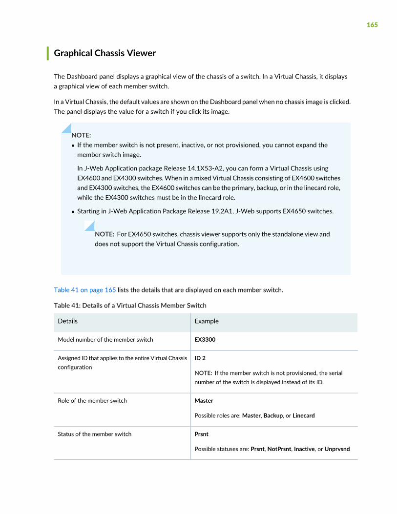
Graphical Chassis Viewer
The Dashboard panel displays a graphical view of the chassis of a switch. In a Virtual Chassis, it displaysa graphical view of each member switch.
In a Virtual Chassis, the default values are shown on theDashboard panel when no chassis image is clicked.The panel displays the value for a switch if you click its image.
NOTE:• If the member switch is not present, inactive, or not provisioned, you cannot expand themember switch image.
In J-Web Application package Release 14.1X53-A2, you can form a Virtual Chassis usingEX4600 and EX4300 switches.When in amixed Virtual Chassis consisting of EX4600 switchesand EX4300 switches, the EX4600 switches can be the primary, backup, or in the linecard role,while the EX4300 switches must be in the linecard role.
• Starting in J-Web Application Package Release 19.2A1, J-Web supports EX4650 switches.
NOTE: For EX4650 switches, chassis viewer supports only the standalone view anddoes not support the Virtual Chassis configuration.
Table 41 on page 165 lists the details that are displayed on each member switch.
Table 41: Details of a Virtual Chassis Member Switch
ExampleDetails
EX3300Model number of the member switch
ID 2
NOTE: If the member switch is not provisioned, the serialnumber of the switch is displayed instead of its ID.
Assigned ID that applies to the entire Virtual Chassisconfiguration
Master
Possible roles are:Master, Backup, or Linecard
Role of the member switch
Prsnt
Possible statuses are: Prsnt, NotPrsnt, Inactive, or Unprvsnd
Status of the member switch
165
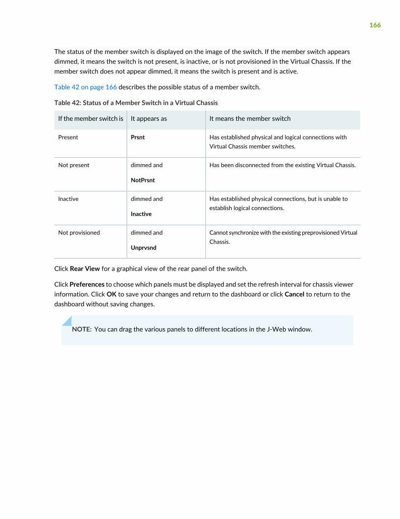
The status of the member switch is displayed on the image of the switch. If the member switch appearsdimmed, it means the switch is not present, is inactive, or is not provisioned in the Virtual Chassis. If themember switch does not appear dimmed, it means the switch is present and is active.
Table 42 on page 166 describes the possible status of a member switch.
Table 42: Status of a Member Switch in a Virtual Chassis
It means the member switchIt appears asIf themember switch is
Has established physical and logical connections withVirtual Chassis member switches.
PrsntPresent
Has been disconnected from the existing Virtual Chassis.dimmed and
NotPrsnt
Not present
Has established physical connections, but is unable toestablish logical connections.
dimmed and
Inactive
Inactive
Cannot synchronizewith the existing preprovisionedVirtualChassis.
dimmed and
Unprvsnd
Not provisioned
Click Rear View for a graphical view of the rear panel of the switch.
Click Preferences to choose which panels must be displayed and set the refresh interval for chassis viewerinformation. Click OK to save your changes and return to the dashboard or click Cancel to return to thedashboard without saving changes.
NOTE: You can drag the various panels to different locations in the J-Web window.
166

System Information Panel
Table 43: System Information
DescriptionField
Indicates the local name of the EX Series switch. The localname of the EX Series switches changeswhen an individualimage is clicked.
For EX4650 switches, indicates the host name of theswitch. Specific host name of the EX4650 switch isdisplayed when you click on the individual line card.
System name
Indicates the model of the EX Series switch. In a VirtualChassis configuration, to indicate the model of a switch,click the image of that switch.
NOTE: In a Virtual Chassis setup for an EX6210, EX8208,or EX8216 switch, the Device model field displays detailsof the primary Routing Engine. To view details of amember, select it.
By default, the EX4650 switches show the model of theprimary switch. When you click on the image, the modelof the switch is displayed.
Device model
167

Table 43: System Information (continued)
DescriptionField
Inventory details
168
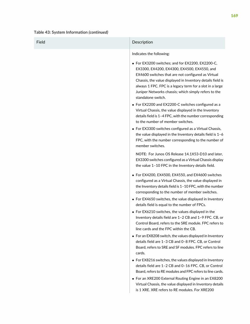
Table 43: System Information (continued)
DescriptionField
Indicates the following:
• For EX3200 switches; and for EX2200, EX2200-C,EX3300, EX4200, EX4300, EX4500, EX4550, andEX4600 switches that are not configured as VirtualChassis, the value displayed in Inventory details field isalways 1 FPC. FPC is a legacy term for a slot in a largeJuniper Networks chassis; which simply refers to thestandalone switch.
• For EX2200 and EX2200-C switches configured as aVirtual Chassis, the value displayed in the Inventorydetails field is 1–4 FPC, with the number correspondingto the number of member switches.
• For EX3300 switches configured as a Virtual Chassis,the value displayed in the Inventory details field is 1–6FPC, with the number corresponding to the number ofmember switches.
NOTE: For Junos OS Release 14.1X53-D10 and later,EX3300 switches configured as a Virtual Chassis displaythe value 1–10 FPC in the Inventory details field.
• For EX4200, EX4500, EX4550, and EX4600 switchesconfigured as a Virtual Chassis, the value displayed inthe Inventory details field is 1–10 FPC, with the numbercorresponding to the number of member switches.
• For EX4650 switches, the value displayed in Inventorydetails field is equal to the number of FPCs.
• For EX6210 switches, the values displayed in theInventory details field are 1–2 CB and 1–9 FPC. CB, orControl Board, refers to the SRE module. FPC refers toline cards and the FPC within the CB.
• For an EX8208 switch, the values displayed in Inventorydetails field are 1–3 CB and 0–8 FPC. CB, or ControlBoard, refers to SRE and SF modules. FPC refers to linecards.
• For EX8216 switches, the values displayed in Inventorydetails field are 1–2 CB and 0–16 FPC. CB, or ControlBoard, refers to REmodules and FPC refers to line cards.
• For an XRE200 External Routing Engine in an EX8200Virtual Chassis, the value displayed in Inventory detailsis 1 XRE. XRE refers to RE modules. For XRE200
169

Table 43: System Information (continued)
DescriptionField
External Routing Engines configured as a Virtual Chassis,the values displayed in Inventory details are 1–2 XREand 0–4 LCC, where LCC refers to the EX8200 line cardchassis.
Indicates the version of the Junos OS image. In a VirtualChassis configuration, the Junos OS image of the primaryswitch is displayed by default. To display the Junos OSimage of a specific switch, click the image of that switch.
NOTE: For EX4650 switches, the Junos OS image of theprimary is displayed by default. To display the Junos OSimage of a specific switch, click the image of that switch.
Junos image
Indicates the version of the boot image that is used. In aVirtual Chassis configuration, the boot image of theprimary switch is displayed by default. To display the bootimage of a specific switch, click the image of that switch.
NOTE: For EX4650 switches, the boot image of theprimary switch is displayed by default. To display the bootimage of a specific switch, click the image of that switch.
Boot image
Indicates the time since the last reboot. In a Virtual Chassisconfiguration, to display the uptime of the specific switch,click the image of that switch.
NOTE: For EX4650 switches, click the image of the switchto display the uptime.
Device uptime
Indicates the time when the switch was last configured.Last configured time
Health Status Panel
Table 44: Health Status
DescriptionField
EX2200, EX2200-C, EX3200, EX3300, EX4200, and EX4300 Switches
170

Table 44: Health Status (continued)
DescriptionField
Indicates the memory used in the Routing Engine. In a Virtual Chassis configuration, thememory utilization value of the primary Routing Engine is displayed.
NOTE: In EX4300 and EX4600 Virtual Chassis, to display the Routing Engine memoryutilization of the primary or backup, click the respective image. J-Web is supported onEX4600 switches only in J-Web Application package Release 14.1X53-A2.
Memory util.
Indicates the usage and capacity of internal flash memory and any external USB flash drive.
NOTE: In EX4300 Virtual Chassis, the flash memory utilization of the primary switch isdisplayed by default. To display the flash memory utilization along with the internal andexternal flash memory utilization details for each switch or line card, mouse over individualswitch or line card images.
In EX4600 Virtual Chassis, to display the flash memory utilization along with the internaland external flash memory utilization details of each switch or line card mouse over thegreen-colored indicator.
Flash
Indicates the chassis temperature status. Temperatures are listed in Celsius and thecorresponding Fahrenheit values.
NOTE: The Temp field is unavailable for a standalone EX2200-C switch.
The Temp field is dynamically available for an EX2200 Virtual Chassis switch based on themodel of the member clicked.
NOTE: In EX4300Virtual Chassis, the temperature of the primary Routing Engine is displayedby default. To display the temperature of the Routing Engine of any switch, click the imageof that switch.
In EX4600 Virtual Chassis, to display the temperature of the Routing Engine of each switch,mouse over the green-colored indicator.
Temp.
Indicates the average CPU usage over 15 minutes. In a Virtual Chassis configuration, onloading the primary or backup switch, the CPU load for that switch's Routing Engine isdisplayed by default. To display the CPU load for a specific switch's Routing Engine, clickthe image of that switch.
CPU load
171
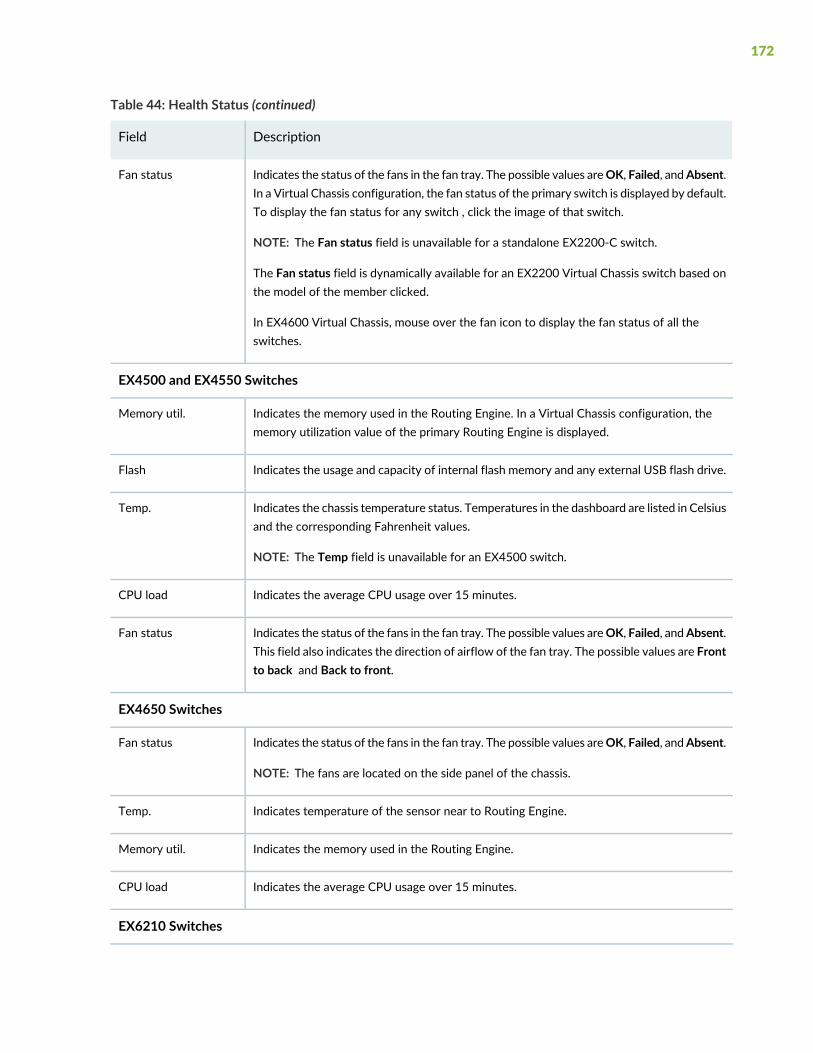
Table 44: Health Status (continued)
DescriptionField
Indicates the status of the fans in the fan tray. The possible values areOK, Failed, andAbsent.In a Virtual Chassis configuration, the fan status of the primary switch is displayed by default.To display the fan status for any switch , click the image of that switch.
NOTE: The Fan status field is unavailable for a standalone EX2200-C switch.
The Fan status field is dynamically available for an EX2200 Virtual Chassis switch based onthe model of the member clicked.
In EX4600 Virtual Chassis, mouse over the fan icon to display the fan status of all theswitches.
Fan status
EX4500 and EX4550 Switches
Indicates the memory used in the Routing Engine. In a Virtual Chassis configuration, thememory utilization value of the primary Routing Engine is displayed.
Memory util.
Indicates the usage and capacity of internal flash memory and any external USB flash drive.Flash
Indicates the chassis temperature status. Temperatures in the dashboard are listed in Celsiusand the corresponding Fahrenheit values.
NOTE: The Temp field is unavailable for an EX4500 switch.
Temp.
Indicates the average CPU usage over 15 minutes.CPU load
Indicates the status of the fans in the fan tray. The possible values areOK, Failed, andAbsent.This field also indicates the direction of airflow of the fan tray. The possible values are Frontto back and Back to front.
Fan status
EX4650 Switches
Indicates the status of the fans in the fan tray. The possible values areOK, Failed, andAbsent.
NOTE: The fans are located on the side panel of the chassis.
Fan status
Indicates temperature of the sensor near to Routing Engine.Temp.
Indicates the memory used in the Routing Engine.Memory util.
Indicates the average CPU usage over 15 minutes.CPU load
EX6210 Switches
172
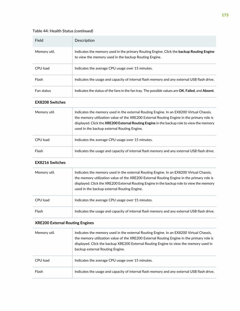
Table 44: Health Status (continued)
DescriptionField
Indicates the memory used in the primary Routing Engine. Click the backup Routing Engineto view the memory used in the backup Routing Engine.
Memory util.
Indicates the average CPU usage over 15 minutes.CPU load
Indicates the usage and capacity of internal flash memory and any external USB flash drive.Flash
Indicates the status of the fans in the fan tray. The possible values areOK, Failed, andAbsent.Fan status
EX8208 Switches
Indicates the memory used in the external Routing Engine. In an EX8200 Virtual Chassis,the memory utilization value of the XRE200 External Routing Engine in the primary role isdisplayed. Click theXRE200 External Routing Engine in the backup role to view thememoryused in the backup external Routing Engine.
Memory util.
Indicates the average CPU usage over 15 minutes.CPU load
Indicates the usage and capacity of internal flash memory and any external USB flash drive.Flash
EX8216 Switches
Indicates the memory used in the external Routing Engine. In an EX8200 Virtual Chassis,the memory utilization value of the XRE200 External Routing Engine in the primary role isdisplayed. Click the XRE200 External Routing Engine in the backup role to view thememoryused in the backup external Routing Engine.
Memory util.
Indicates the average CPU usage over 15 minutes.CPU load
Indicates the usage and capacity of internal flash memory and any external USB flash drive.Flash
XRE200 External Routing Engines
Indicates the memory used in the external Routing Engine. In an EX8200 Virtual Chassis,the memory utilization value of the XRE200 External Routing Engine in the primary role isdisplayed. Click the backup XRE200 External Routing Engine to view the memory used inbackup external Routing Engine.
Memory util.
Indicates the average CPU usage over 15 minutes.CPU load
Indicates the usage and capacity of internal flash memory and any external USB flash drive.Flash
173

Table 44: Health Status (continued)
DescriptionField
Indicates the status of the fans in the fan tray. The possible values areOK, Failed, andAbsent.Fan Status
Capacity Utilization Panel
Table 45: Capacity Utilization
DescriptionField
Indicates the number of active ports in the switch.Configured Virtual Chassis ports (VCPs) are considered asactive ports.
Number of active ports
Indicates the number of ports in the switch.
NOTE: In EX3300 and EX4600 Virtual Chassis, the totalnumber of ports of all of the switches is displayed.
NOTE: For EX4650 switches, on loading the switch, theconsolidated values for all the FPCs are displayed bydefault.
Total number of ports
Indicates the number of MAC table entries.Used-up MAC-Table entries
Indicates the maximum number of MAC table entriespermitted.
NOTE: For EX4650 switches, the supported maximumnumber of MAC table entries are 288000.
Supported MAC-Table entries
Indicates the number of VLANs configured.
NOTE: Only tagged VLANs are counted.
Number of VLANs configured
Indicates the maximum number of VLANs supported.
NOTE: For EX4650 switches, the supported maximumnumber of VLANs are 4094.
Number of VLANs supported
174
Alarms Panel
Displays information about the last five alarms raised in the system. For example, if there are 5 majoralarms, then details of all 5 major alarms are displayed. If there are 4 major alarms and 3 minor alarms,then details of the 4 major alarms and 1 minor alarm are displayed. Major alarms are displayed in red andminor alarms are displayed in yellow.
In an EX8200 Virtual Chassis, the top 5 alarms for the primary external Routing Engine are displayed bydefault. If you select an EX8200 member switch of the Virtual Chassis, the top 5 alarms for that memberswitch are displayed.
File System Usage
To display the file system storage details of a switch in the backup or line card role, click the image of thatswitch.
For EX4650 switches, the directory, space used, and the file type details are displayed. By default, primaryswitch file system storage details are displayed. When you click the image, line card switch file systemstorage details are displayed.
Chassis Viewer
Click the Rear View button to see the back of the chassis image. Click the Front View button to see thefront of the chassis image. In a Virtual Chassis configuration, the Rear View button is disabled if the switchis not selected.
NOTE: For EX4650 switches, chassis viewer supports only the standalone view and does notsupport Virtual Chassis configuration.
• Table 46 on page 176—Describes the chassis viewer for EX2200 switches.
• Table 47 on page 176—Describes the chassis viewer for EX2200-C switches.
• Table 48 on page 177—Describes the chassis viewer for EX3200, EX3300, and EX4200 switches.
• Table 49 on page 179—Describes the chassis viewer for EX4300 switches.
• Table 50 on page 181—Describes the chassis viewer for EX4500 switches.
• Table 51 on page 182—Describes the chassis viewer for EX4550 switches.
175
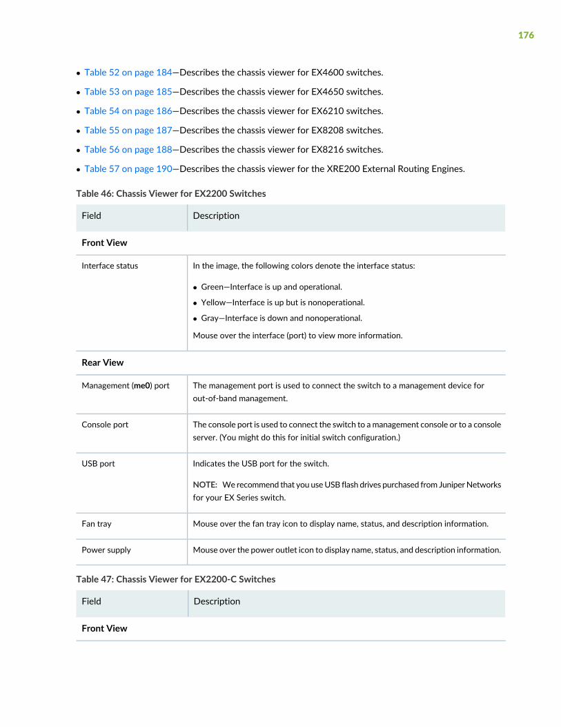
• Table 52 on page 184—Describes the chassis viewer for EX4600 switches.
• Table 53 on page 185—Describes the chassis viewer for EX4650 switches.
• Table 54 on page 186—Describes the chassis viewer for EX6210 switches.
• Table 55 on page 187—Describes the chassis viewer for EX8208 switches.
• Table 56 on page 188—Describes the chassis viewer for EX8216 switches.
• Table 57 on page 190—Describes the chassis viewer for the XRE200 External Routing Engines.
Table 46: Chassis Viewer for EX2200 Switches
DescriptionField
Front View
In the image, the following colors denote the interface status:
• Green—Interface is up and operational.
• Yellow—Interface is up but is nonoperational.
• Gray—Interface is down and nonoperational.
Mouse over the interface (port) to view more information.
Interface status
Rear View
The management port is used to connect the switch to a management device forout-of-band management.
Management (me0) port
The console port is used to connect the switch to amanagement console or to a consoleserver. (You might do this for initial switch configuration.)
Console port
Indicates the USB port for the switch.
NOTE: Werecommend that you useUSB flash drives purchased from JuniperNetworksfor your EX Series switch.
USB port
Mouse over the fan tray icon to display name, status, and description information.Fan tray
Mouse over the power outlet icon to display name, status, and description information.Power supply
Table 47: Chassis Viewer for EX2200-C Switches
DescriptionField
Front View
176
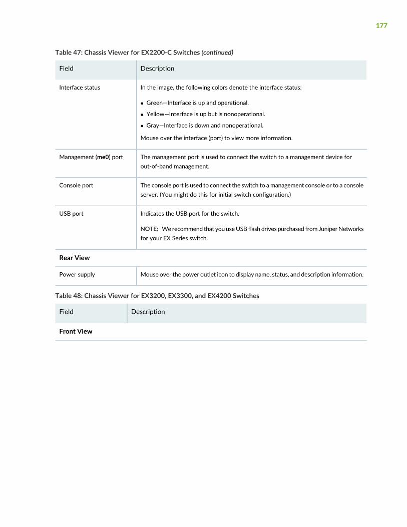
Table 47: Chassis Viewer for EX2200-C Switches (continued)
DescriptionField
In the image, the following colors denote the interface status:
• Green—Interface is up and operational.
• Yellow—Interface is up but is nonoperational.
• Gray—Interface is down and nonoperational.
Mouse over the interface (port) to view more information.
Interface status
The management port is used to connect the switch to a management device forout-of-band management.
Management (me0) port
The console port is used to connect the switch to amanagement console or to a consoleserver. (You might do this for initial switch configuration.)
Console port
Indicates the USB port for the switch.
NOTE: Werecommend that you useUSB flash drives purchased from JuniperNetworksfor your EX Series switch.
USB port
Rear View
Mouse over the power outlet icon to display name, status, and description information.Power supply
Table 48: Chassis Viewer for EX3200, EX3300, and EX4200 Switches
DescriptionField
Front View
177
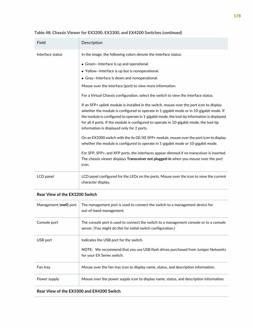
Table 48: Chassis Viewer for EX3200, EX3300, and EX4200 Switches (continued)
DescriptionField
In the image, the following colors denote the interface status:
• Green—Interface is up and operational.
• Yellow—Interface is up but is nonoperational.
• Gray—Interface is down and nonoperational.
Mouse over the interface (port) to view more information.
For a Virtual Chassis configuration, select the switch to view the interface status.
If an SFP+ uplink module is installed in the switch, mouse over the port icon to displaywhether the module is configured to operate in 1-gigabit mode or in 10-gigabit mode. Ifthemodule is configured to operate in 1-gigabit mode, the tool tip information is displayedfor all 4 ports. If the module is configured to operate in 10-gigabit mode, the tool tipinformation is displayed only for 2 ports.
On an EX3300 switchwith the 4x GE/XE SFP+module, mouse over the port icon to displaywhether the module is configured to operate in 1-gigabit mode or 10-gigabit mode.
For SFP, SFP+, and XFP ports, the interfaces appear dimmed if no transceiver is inserted.The chassis viewer displays Transceiver not plugged-in when you mouse over the porticon.
Interface status
LCD panel configured for the LEDs on the ports. Mouse over the icon to view the currentcharacter display.
LCD panel
Rear View of the EX3200 Switch
The management port is used to connect the switch to a management device forout-of-band management.
Management (me0) port
The console port is used to connect the switch to a management console or to a consoleserver. (You might do this for initial switch configuration.)
Console port
Indicates the USB port for the switch.
NOTE: We recommend that you use USB flash drives purchased from Juniper Networksfor your EX Series switch.
USB port
Mouse over the fan tray icon to display name, status, and description information.Fan tray
Mouse over the power supply icon to display name, status, and description information.Power supply
Rear View of the EX3300 and EX4200 Switch
178
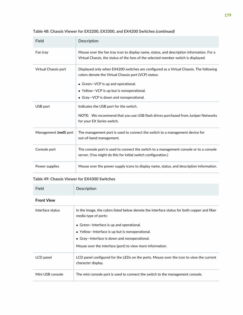
Table 48: Chassis Viewer for EX3200, EX3300, and EX4200 Switches (continued)
DescriptionField
Mouse over the fan tray icon to display name, status, and description information. For aVirtual Chassis, the status of the fans of the selected member switch is displayed.
Fan tray
Displayed only when EX4200 switches are configured as a Virtual Chassis. The followingcolors denote the Virtual Chassis port (VCP) status:
• Green—VCP is up and operational.
• Yellow—VCP is up but is nonoperational.
• Gray—VCP is down and nonoperational.
Virtual Chassis port
Indicates the USB port for the switch.
NOTE: We recommend that you use USB flash drives purchased from Juniper Networksfor your EX Series switch.
USB port
The management port is used to connect the switch to a management device forout-of-band management.
Management (me0) port
The console port is used to connect the switch to a management console or to a consoleserver. (You might do this for initial switch configuration.)
Console port
Mouse over the power supply icons to display name, status, and description information.Power supplies
Table 49: Chassis Viewer for EX4300 Switches
DescriptionField
Front View
In the image, the colors listed below denote the interface status for both copper and fibermedia type of ports:
• Green—Interface is up and operational.
• Yellow—Interface is up but is nonoperational.
• Gray—Interface is down and nonoperational.
Mouse over the interface (port) to view more information.
Interface status
LCD panel configured for the LEDs on the ports. Mouse over the icon to view the currentcharacter display.
LCD panel
The mini console port is used to connect the switch to the management console.Mini USB console
179
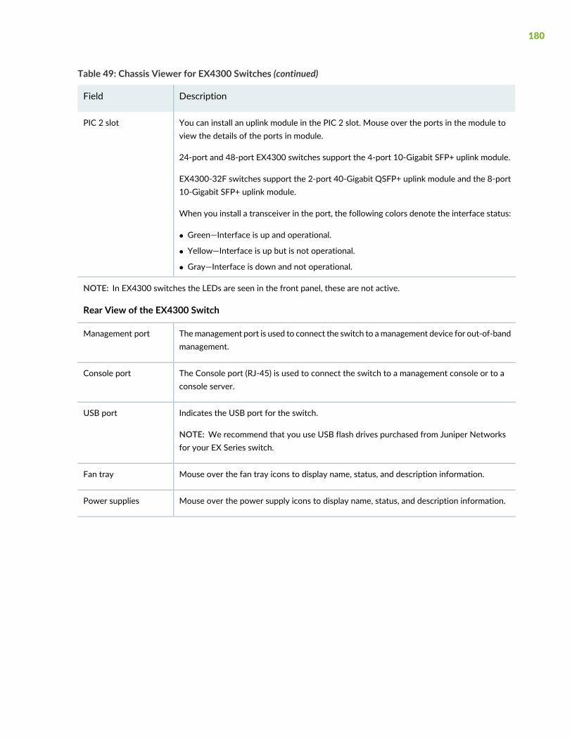
Table 49: Chassis Viewer for EX4300 Switches (continued)
DescriptionField
You can install an uplink module in the PIC 2 slot. Mouse over the ports in the module toview the details of the ports in module.
24-port and 48-port EX4300 switches support the 4-port 10-Gigabit SFP+ uplink module.
EX4300-32F switches support the 2-port 40-Gigabit QSFP+ uplink module and the 8-port10-Gigabit SFP+ uplink module.
When you install a transceiver in the port, the following colors denote the interface status:
• Green—Interface is up and operational.
• Yellow—Interface is up but is not operational.
• Gray—Interface is down and not operational.
PIC 2 slot
NOTE: In EX4300 switches the LEDs are seen in the front panel, these are not active.
Rear View of the EX4300 Switch
Themanagement port is used to connect the switch to amanagement device for out-of-bandmanagement.
Management port
The Console port (RJ-45) is used to connect the switch to a management console or to aconsole server.
Console port
Indicates the USB port for the switch.
NOTE: We recommend that you use USB flash drives purchased from Juniper Networksfor your EX Series switch.
USB port
Mouse over the fan tray icons to display name, status, and description information.Fan tray
Mouse over the power supply icons to display name, status, and description information.Power supplies
180
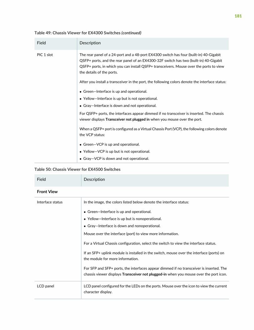
Table 49: Chassis Viewer for EX4300 Switches (continued)
DescriptionField
The rear panel of a 24-port and a 48-port EX4300 switch has four (built-in) 40-GigabitQSFP+ ports, and the rear panel of an EX4300-32F switch has two (built-in) 40-GigabitQSFP+ ports, in which you can install QSFP+ transceivers. Mouse over the ports to viewthe details of the ports.
After you install a transceiver in the port, the following colors denote the interface status:
• Green—Interface is up and operational.
• Yellow—Interface is up but is not operational.
• Gray—Interface is down and not operational.
For QSFP+ ports, the interfaces appear dimmed if no transceiver is inserted. The chassisviewer displays Transceiver not plugged in when you mouse over the port.
When aQSFP+ port is configured as a Virtual Chassis Port (VCP), the following colors denotethe VCP status:
• Green—VCP is up and operational.
• Yellow—VCP is up but is not operational.
• Gray—VCP is down and not operational.
PIC 1 slot
Table 50: Chassis Viewer for EX4500 Switches
DescriptionField
Front View
In the image, the colors listed below denote the interface status:
• Green—Interface is up and operational.
• Yellow—Interface is up but is nonoperational.
• Gray—Interface is down and nonoperational.
Mouse over the interface (port) to view more information.
For a Virtual Chassis configuration, select the switch to view the interface status.
If an SFP+ uplink module is installed in the switch, mouse over the interface (ports) onthe module for more information.
For SFP and SFP+ ports, the interfaces appear dimmed if no transceiver is inserted. Thechassis viewer displays Transceiver not plugged-in when you mouse over the port icon.
Interface status
LCD panel configured for the LEDs on the ports. Mouse over the icon to view the currentcharacter display.
LCD panel
181
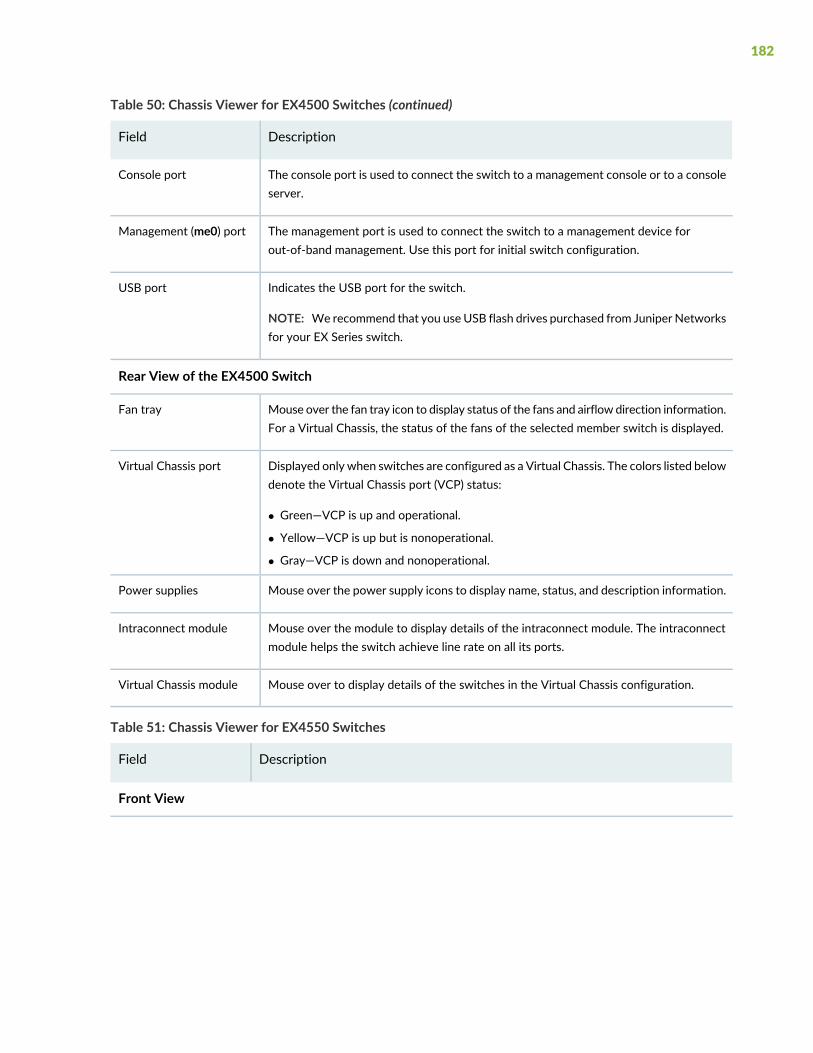
Table 50: Chassis Viewer for EX4500 Switches (continued)
DescriptionField
The console port is used to connect the switch to a management console or to a consoleserver.
Console port
The management port is used to connect the switch to a management device forout-of-band management. Use this port for initial switch configuration.
Management (me0) port
Indicates the USB port for the switch.
NOTE: We recommend that you use USB flash drives purchased from Juniper Networksfor your EX Series switch.
USB port
Rear View of the EX4500 Switch
Mouse over the fan tray icon to display status of the fans and airflow direction information.For a Virtual Chassis, the status of the fans of the selected member switch is displayed.
Fan tray
Displayed only when switches are configured as a Virtual Chassis. The colors listed belowdenote the Virtual Chassis port (VCP) status:
• Green—VCP is up and operational.
• Yellow—VCP is up but is nonoperational.
• Gray—VCP is down and nonoperational.
Virtual Chassis port
Mouse over the power supply icons to display name, status, and description information.Power supplies
Mouse over the module to display details of the intraconnect module. The intraconnectmodule helps the switch achieve line rate on all its ports.
Intraconnect module
Mouse over to display details of the switches in the Virtual Chassis configuration.Virtual Chassis module
Table 51: Chassis Viewer for EX4550 Switches
DescriptionField
Front View
182
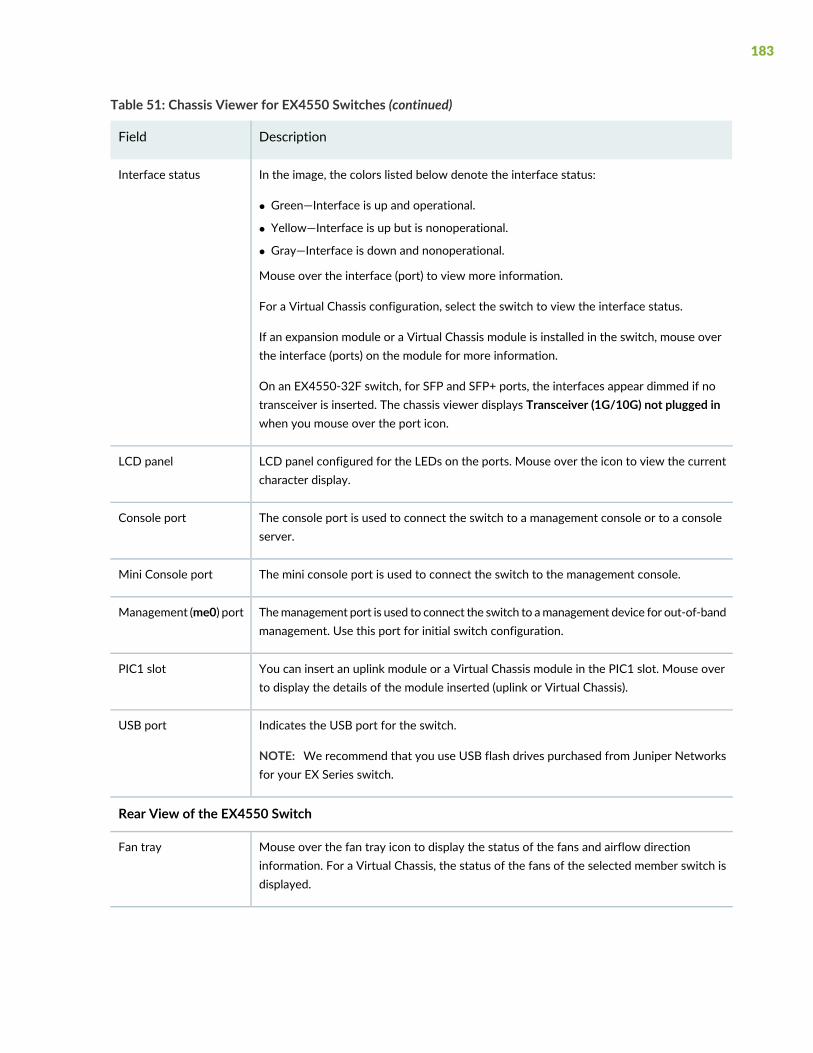
Table 51: Chassis Viewer for EX4550 Switches (continued)
DescriptionField
In the image, the colors listed below denote the interface status:
• Green—Interface is up and operational.
• Yellow—Interface is up but is nonoperational.
• Gray—Interface is down and nonoperational.
Mouse over the interface (port) to view more information.
For a Virtual Chassis configuration, select the switch to view the interface status.
If an expansion module or a Virtual Chassis module is installed in the switch, mouse overthe interface (ports) on the module for more information.
On an EX4550-32F switch, for SFP and SFP+ ports, the interfaces appear dimmed if notransceiver is inserted. The chassis viewer displays Transceiver (1G/10G) not plugged inwhen you mouse over the port icon.
Interface status
LCD panel configured for the LEDs on the ports. Mouse over the icon to view the currentcharacter display.
LCD panel
The console port is used to connect the switch to a management console or to a consoleserver.
Console port
The mini console port is used to connect the switch to the management console.Mini Console port
Themanagement port is used to connect the switch to amanagement device for out-of-bandmanagement. Use this port for initial switch configuration.
Management (me0) port
You can insert an uplink module or a Virtual Chassis module in the PIC1 slot. Mouse overto display the details of the module inserted (uplink or Virtual Chassis).
PIC1 slot
Indicates the USB port for the switch.
NOTE: We recommend that you use USB flash drives purchased from Juniper Networksfor your EX Series switch.
USB port
Rear View of the EX4550 Switch
Mouse over the fan tray icon to display the status of the fans and airflow directioninformation. For a Virtual Chassis, the status of the fans of the selected member switch isdisplayed.
Fan tray
183
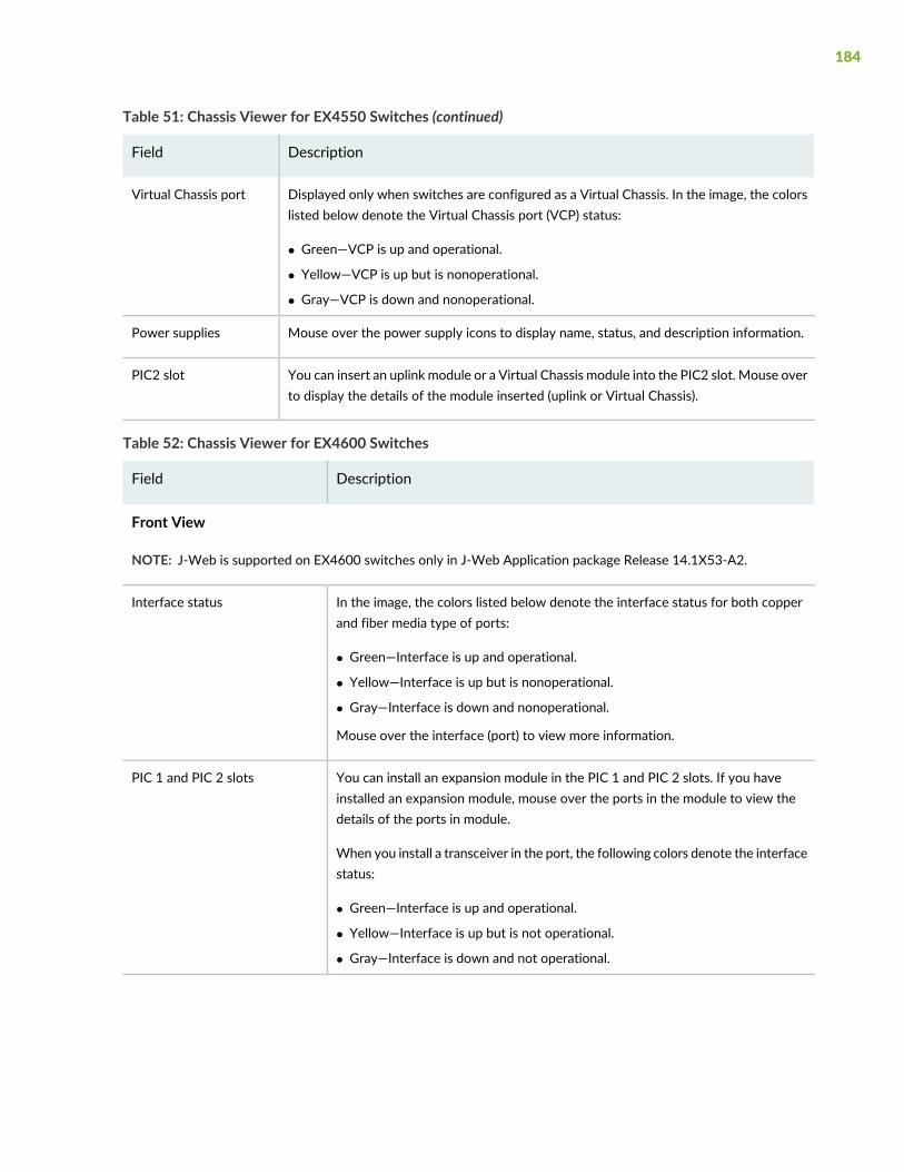
Table 51: Chassis Viewer for EX4550 Switches (continued)
DescriptionField
Displayed only when switches are configured as a Virtual Chassis. In the image, the colorslisted below denote the Virtual Chassis port (VCP) status:
• Green—VCP is up and operational.
• Yellow—VCP is up but is nonoperational.
• Gray—VCP is down and nonoperational.
Virtual Chassis port
Mouse over the power supply icons to display name, status, and description information.Power supplies
You can insert an uplink module or a Virtual Chassis module into the PIC2 slot. Mouse overto display the details of the module inserted (uplink or Virtual Chassis).
PIC2 slot
Table 52: Chassis Viewer for EX4600 Switches
DescriptionField
Front View
NOTE: J-Web is supported on EX4600 switches only in J-Web Application package Release 14.1X53-A2.
In the image, the colors listed below denote the interface status for both copperand fiber media type of ports:
• Green—Interface is up and operational.
• Yellow—Interface is up but is nonoperational.
• Gray—Interface is down and nonoperational.
Mouse over the interface (port) to view more information.
Interface status
You can install an expansion module in the PIC 1 and PIC 2 slots. If you haveinstalled an expansion module, mouse over the ports in the module to view thedetails of the ports in module.
When you install a transceiver in the port, the following colors denote the interfacestatus:
• Green—Interface is up and operational.
• Yellow—Interface is up but is not operational.
• Gray—Interface is down and not operational.
PIC 1 and PIC 2 slots
184
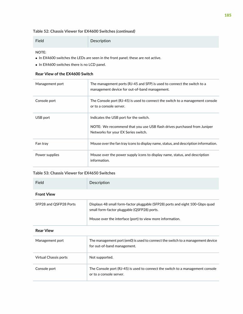
Table 52: Chassis Viewer for EX4600 Switches (continued)
DescriptionField
NOTE:• In EX4600 switches the LEDs are seen in the front panel; these are not active.
• In EX4600 switches there is no LCD panel.
Rear View of the EX4600 Switch
The management ports (RJ-45 and SFP) is used to connect the switch to amanagement device for out-of-band management.
Management port
The Console port (RJ-45) is used to connect the switch to a management consoleor to a console server.
Console port
Indicates the USB port for the switch.
NOTE: We recommend that you use USB flash drives purchased from JuniperNetworks for your EX Series switch.
USB port
Mouse over the fan tray icons to display name, status, and description information.Fan tray
Mouse over the power supply icons to display name, status, and descriptioninformation.
Power supplies
Table 53: Chassis Viewer for EX4650 Switches
DescriptionField
Front View
Displays 48 small form-factor pluggable (SFP28) ports and eight 100-Gbps quadsmall form-factor pluggable (QSFP28) ports.
Mouse over the interface (port) to view more information.
SFP28 and QSFP28 Ports
Rear View
Themanagement port (em0) is used to connect the switch to amanagement devicefor out-of-band management.
Management port
Not supported.Virtual Chassis ports
The Console port (RJ-45) is used to connect the switch to a management consoleor to a console server.
Console port
185
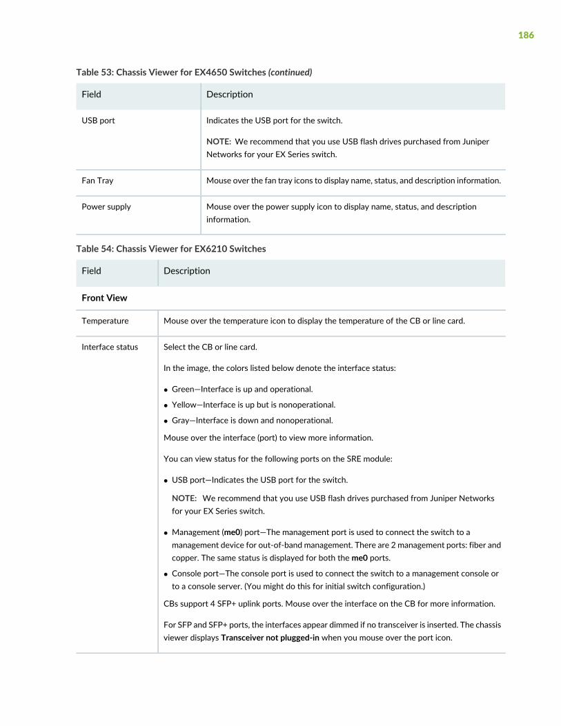
Table 53: Chassis Viewer for EX4650 Switches (continued)
DescriptionField
Indicates the USB port for the switch.
NOTE: We recommend that you use USB flash drives purchased from JuniperNetworks for your EX Series switch.
USB port
Mouse over the fan tray icons to display name, status, and description information.Fan Tray
Mouse over the power supply icon to display name, status, and descriptioninformation.
Power supply
Table 54: Chassis Viewer for EX6210 Switches
DescriptionField
Front View
Mouse over the temperature icon to display the temperature of the CB or line card.Temperature
Select the CB or line card.
In the image, the colors listed below denote the interface status:
• Green—Interface is up and operational.
• Yellow—Interface is up but is nonoperational.
• Gray—Interface is down and nonoperational.
Mouse over the interface (port) to view more information.
You can view status for the following ports on the SRE module:
• USB port—Indicates the USB port for the switch.
NOTE: We recommend that you use USB flash drives purchased from Juniper Networksfor your EX Series switch.
• Management (me0) port—The management port is used to connect the switch to amanagement device for out-of-band management. There are 2 management ports: fiber andcopper. The same status is displayed for both the me0 ports.
• Console port—The console port is used to connect the switch to a management console orto a console server. (You might do this for initial switch configuration.)
CBs support 4 SFP+ uplink ports. Mouse over the interface on the CB for more information.
For SFP and SFP+ ports, the interfaces appear dimmed if no transceiver is inserted. The chassisviewer displays Transceiver not plugged-in when you mouse over the port icon.
Interface status
186
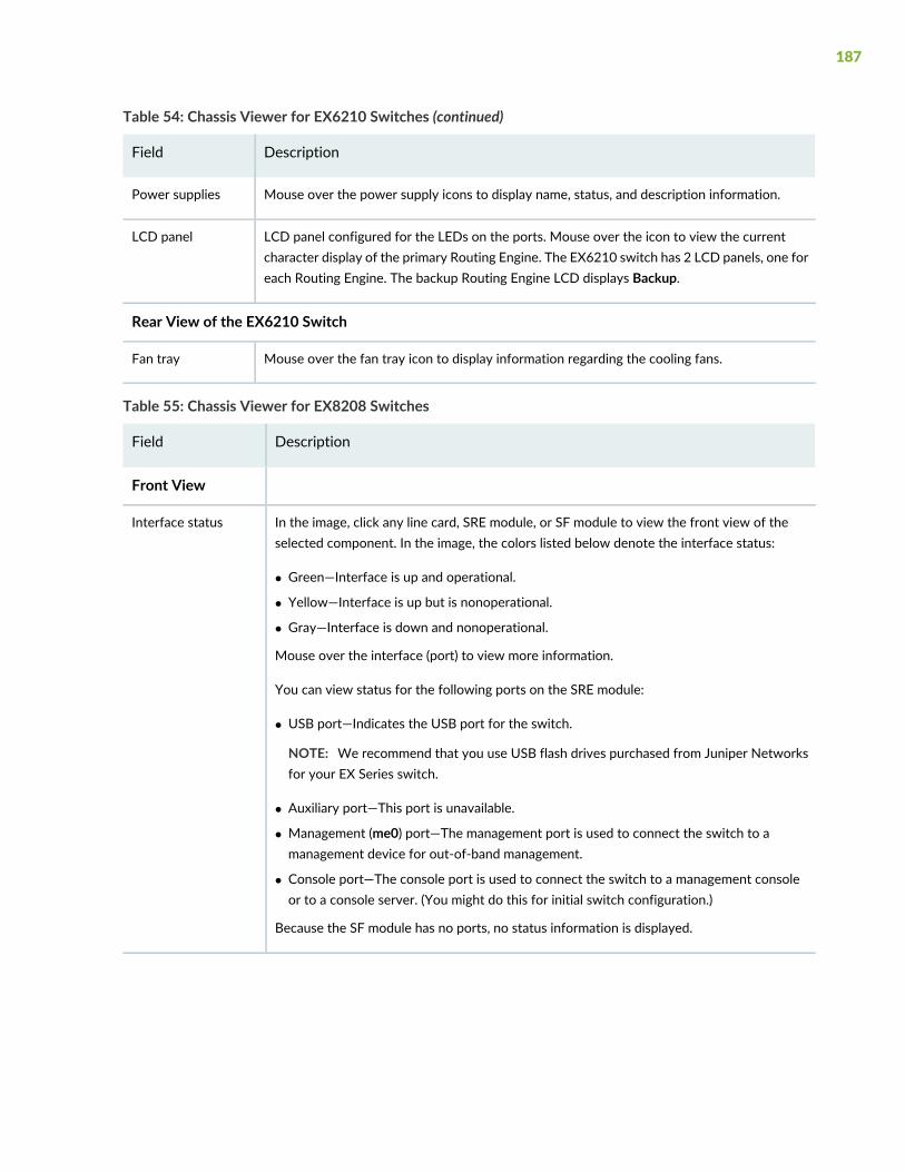
Table 54: Chassis Viewer for EX6210 Switches (continued)
DescriptionField
Mouse over the power supply icons to display name, status, and description information.Power supplies
LCD panel configured for the LEDs on the ports. Mouse over the icon to view the currentcharacter display of the primary Routing Engine. The EX6210 switch has 2 LCD panels, one foreach Routing Engine. The backup Routing Engine LCD displays Backup.
LCD panel
Rear View of the EX6210 Switch
Mouse over the fan tray icon to display information regarding the cooling fans.Fan tray
Table 55: Chassis Viewer for EX8208 Switches
DescriptionField
Front View
In the image, click any line card, SRE module, or SF module to view the front view of theselected component. In the image, the colors listed below denote the interface status:
• Green—Interface is up and operational.
• Yellow—Interface is up but is nonoperational.
• Gray—Interface is down and nonoperational.
Mouse over the interface (port) to view more information.
You can view status for the following ports on the SRE module:
• USB port—Indicates the USB port for the switch.
NOTE: We recommend that you use USB flash drives purchased from Juniper Networksfor your EX Series switch.
• Auxiliary port—This port is unavailable.
• Management (me0) port—The management port is used to connect the switch to amanagement device for out-of-band management.
• Console port—The console port is used to connect the switch to a management consoleor to a console server. (You might do this for initial switch configuration.)
Because the SF module has no ports, no status information is displayed.
Interface status
187
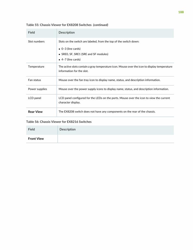
Table 55: Chassis Viewer for EX8208 Switches (continued)
DescriptionField
Slots on the switch are labeled, from the top of the switch down:
• 0–3 (line cards)
• SRE0, SF, SRE1 (SRE and SF modules)
• 4–7 (line cards)
Slot numbers
The active slots contain a gray temperature icon. Mouse over the icon to display temperatureinformation for the slot.
Temperature
Mouse over the fan tray icon to display name, status, and description information.Fan status
Mouse over the power supply icons to display name, status, and description information.Power supplies
LCD panel configured for the LEDs on the ports. Mouse over the icon to view the currentcharacter display.
LCD panel
The EX8208 switch does not have any components on the rear of the chassis.Rear View
Table 56: Chassis Viewer for EX8216 Switches
DescriptionField
Front View
188
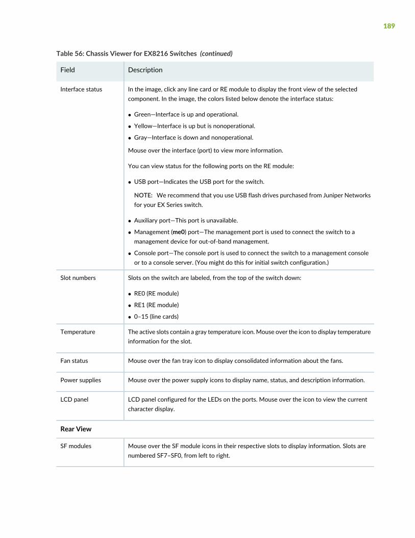
Table 56: Chassis Viewer for EX8216 Switches (continued)
DescriptionField
In the image, click any line card or RE module to display the front view of the selectedcomponent. In the image, the colors listed below denote the interface status:
• Green—Interface is up and operational.
• Yellow—Interface is up but is nonoperational.
• Gray—Interface is down and nonoperational.
Mouse over the interface (port) to view more information.
You can view status for the following ports on the RE module:
• USB port—Indicates the USB port for the switch.
NOTE: We recommend that you use USB flash drives purchased from Juniper Networksfor your EX Series switch.
• Auxiliary port—This port is unavailable.
• Management (me0) port—The management port is used to connect the switch to amanagement device for out-of-band management.
• Console port—The console port is used to connect the switch to a management consoleor to a console server. (You might do this for initial switch configuration.)
Interface status
Slots on the switch are labeled, from the top of the switch down:
• RE0 (RE module)
• RE1 (RE module)
• 0–15 (line cards)
Slot numbers
The active slots contain a gray temperature icon.Mouse over the icon to display temperatureinformation for the slot.
Temperature
Mouse over the fan tray icon to display consolidated information about the fans.Fan status
Mouse over the power supply icons to display name, status, and description information.Power supplies
LCD panel configured for the LEDs on the ports. Mouse over the icon to view the currentcharacter display.
LCD panel
Rear View
Mouse over the SF module icons in their respective slots to display information. Slots arenumbered SF7–SF0, from left to right.
SF modules
189
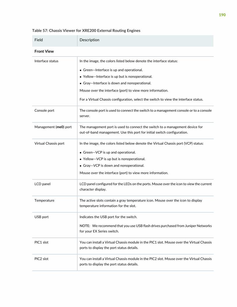
Table 57: Chassis Viewer for XRE200 External Routing Engines
DescriptionField
Front View
In the image, the colors listed below denote the interface status:
• Green—Interface is up and operational.
• Yellow—Interface is up but is nonoperational.
• Gray—Interface is down and nonoperational.
Mouse over the interface (port) to view more information.
For a Virtual Chassis configuration, select the switch to view the interface status.
Interface status
The console port is used to connect the switch to a management console or to a consoleserver.
Console port
The management port is used to connect the switch to a management device forout-of-band management. Use this port for initial switch configuration.
Management (me0) port
In the image, the colors listed below denote the Virtual Chassis port (VCP) status:
• Green—VCP is up and operational.
• Yellow—VCP is up but is nonoperational.
• Gray—VCP is down and nonoperational.
Mouse over the interface (port) to view more information.
Virtual Chassis port
LCD panel configured for the LEDs on the ports. Mouse over the icon to view the currentcharacter display.
LCD panel
The active slots contain a gray temperature icon. Mouse over the icon to displaytemperature information for the slot.
Temperature
Indicates the USB port for the switch.
NOTE: We recommend that you useUSB flash drives purchased from Juniper Networksfor your EX Series switch.
USB port
You can install a Virtual Chassis module in the PIC1 slot. Mouse over the Virtual Chassisports to display the port status details.
PIC1 slot
You can install a Virtual Chassis module in the PIC2 slot. Mouse over the Virtual Chassisports to display the port status details.
PIC2 slot
190
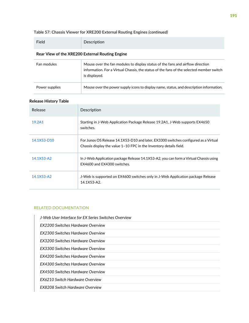
Table 57: Chassis Viewer for XRE200 External Routing Engines (continued)
DescriptionField
Rear View of the XRE200 External Routing Engine
Mouse over the fan modules to display status of the fans and airflow directioninformation. For a Virtual Chassis, the status of the fans of the selected member switchis displayed.
Fan modules
Mouse over the power supply icons to display name, status, and description information.Power supplies
Release History Table
DescriptionRelease
Starting in J-Web Application Package Release 19.2A1, J-Web supports EX4650switches.
19.2A1
For Junos OS Release 14.1X53-D10 and later, EX3300 switches configured as a VirtualChassis display the value 1–10 FPC in the Inventory details field.
14.1X53-D10
In J-WebApplication package Release 14.1X53-A2, you can form a Virtual Chassis usingEX4600 and EX4300 switches.
14.1X53-A2
J-Web is supported on EX4600 switches only in J-Web Application package Release14.1X53-A2.
14.1X53-A2
RELATED DOCUMENTATION
J-Web User Interface for EX Series Switches Overview
EX2200 Switches Hardware Overview
EX2300 Switches Hardware Overview
EX3200 Switches Hardware Overview
EX3300 Switches Hardware Overview
EX4200 Switches Hardware Overview
EX4300 Switches Hardware Overview
EX4500 Switches Hardware Overview
EX6210 Switch Hardware Overview
EX8208 Switch Hardware Overview
191

EX8216 Switch Hardware Overview
Check Active Alarms with the J-Web Interface | 219
XRE200 External Routing Engine Hardware Guide
192

4CHAPTER
Maintaining Components
Maintaining the EX3400 Switch Cooling System | 194
Maintaining the EX3400 Power System | 197
Maintaining a Transceiver | 204
Maintaining Fiber-Optic Cables | 210

Maintaining the EX3400 Switch Cooling System
IN THIS SECTION
Removing a Fan Module from an EX3400 Switch | 194
Installing a Fan Module in an EX3400 Switch | 195
Removing a Fan Module from an EX3400 Switch
Each fan module in EX3400 switches is a hot-removable and hot-insertable field-replaceable unit (FRU)installed in the rear panel of the switch: You can remove and replace it without powering off the switchor disrupting switch functions.
NOTE: If you remove both the fan modules, you must replace at least one fan module withinfour minutes for the switch to operate without disrupting its functions.
Ensure that you have the following parts and tools available:
• Phillips (+) screwdriver, number 2
• An antistatic bag or an antistatic mat
• A replacement fan module
1. Place the antistatic bag or the antistatic mat on a flat, stable surface.
2. Loosen the captive screws on the front faceplate of the fan module by using your fingers. If you areunable to loosen the captive screws by using your fingers, use the screwdriver.
WARNING: To prevent injury, do not touch the fan with your hands or any toolsas you slide the fan module out of the chassis—the fan might still be running.
3. Grasp the handle on the fan module and pull it firmly to slide the fan module out of the chassis.
4. Place the fan module in the antistatic bag or on the antistatic mat placed on a flat, stable surface.
194
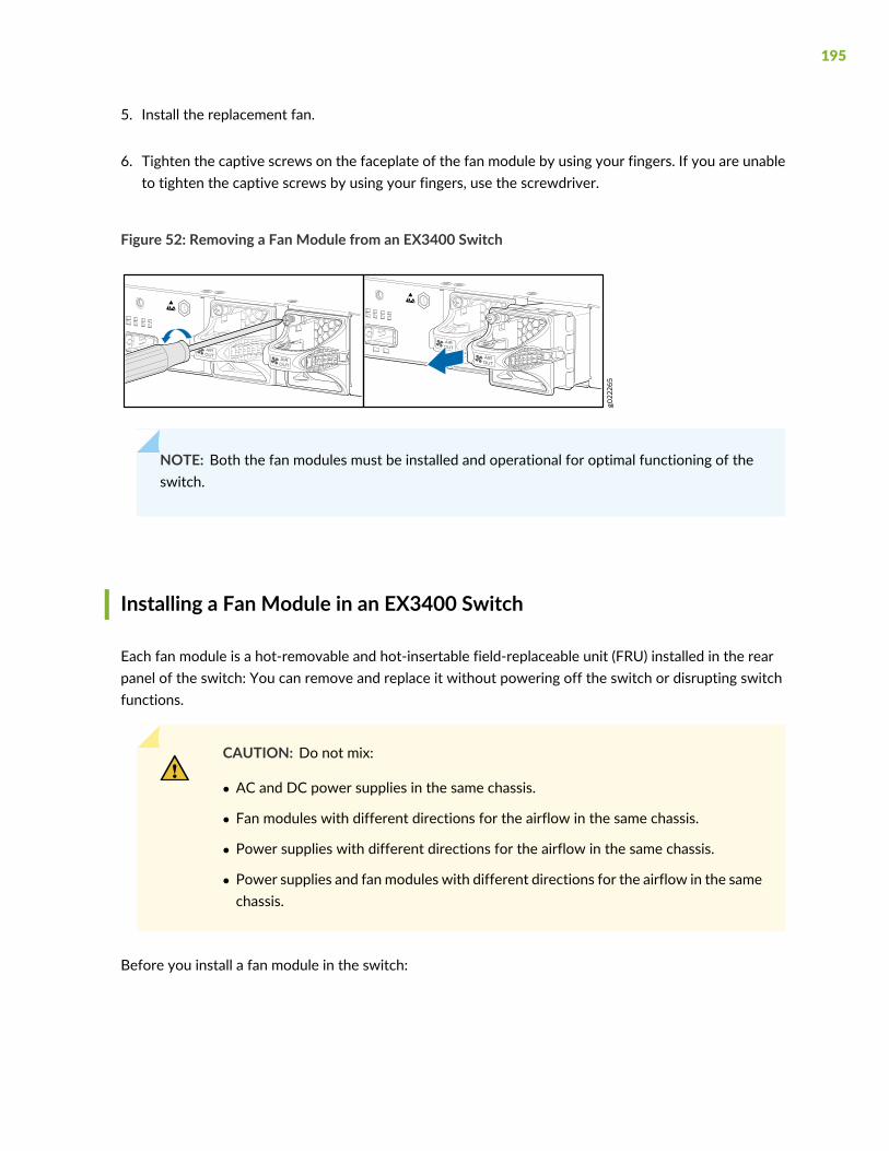
5. Install the replacement fan.
6. Tighten the captive screws on the faceplate of the fan module by using your fingers. If you are unableto tighten the captive screws by using your fingers, use the screwdriver.
Figure 52: Removing a Fan Module from an EX3400 Switch
NOTE: Both the fan modules must be installed and operational for optimal functioning of theswitch.
Installing a Fan Module in an EX3400 Switch
Each fan module is a hot-removable and hot-insertable field-replaceable unit (FRU) installed in the rearpanel of the switch: You can remove and replace it without powering off the switch or disrupting switchfunctions.
CAUTION: Do not mix:
• AC and DC power supplies in the same chassis.
• Fan modules with different directions for the airflow in the same chassis.
• Power supplies with different directions for the airflow in the same chassis.
• Power supplies and fan modules with different directions for the airflow in the samechassis.
Before you install a fan module in the switch:
195
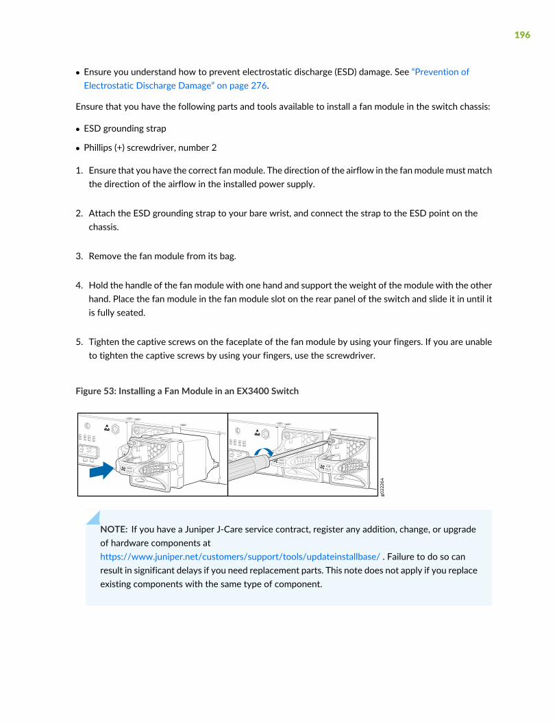
• Ensure you understand how to prevent electrostatic discharge (ESD) damage. See “Prevention ofElectrostatic Discharge Damage” on page 276.
Ensure that you have the following parts and tools available to install a fan module in the switch chassis:
• ESD grounding strap
• Phillips (+) screwdriver, number 2
1. Ensure that you have the correct fanmodule. The direction of the airflow in the fanmodulemust matchthe direction of the airflow in the installed power supply.
2. Attach the ESD grounding strap to your bare wrist, and connect the strap to the ESD point on thechassis.
3. Remove the fan module from its bag.
4. Hold the handle of the fan module with one hand and support the weight of the module with the otherhand. Place the fan module in the fan module slot on the rear panel of the switch and slide it in until itis fully seated.
5. Tighten the captive screws on the faceplate of the fan module by using your fingers. If you are unableto tighten the captive screws by using your fingers, use the screwdriver.
Figure 53: Installing a Fan Module in an EX3400 Switch
NOTE: If you have a Juniper J-Care service contract, register any addition, change, or upgradeof hardware components athttps://www.juniper.net/customers/support/tools/updateinstallbase/ . Failure to do so canresult in significant delays if you need replacement parts. This note does not apply if you replaceexisting components with the same type of component.
196

SEE ALSO
EX3400 Cooling System | 38
Maintaining the EX3400 Power System
IN THIS SECTION
Removing an AC Power Supply from an EX3400 Switch | 197
Installing an AC Power Supply in an EX3400 Switch | 199
Removing a DC Power Supply from an EX3400 Switch | 200
Installing a DC Power Supply in an EX3400 Switch | 202
Removing an AC Power Supply from an EX3400 Switch
The power supplies in EX3400 switches are hot-removable and hot-insertable field-replaceable units(FRUs) installed in the rear panel of the switch: You can remove and replace them without powering offthe switch or disrupting switch functions.
NOTE: If only one power supply is installed in the switch, you must power off the switch beforeremoving the power supply.
Before you remove a power supply from an EX3400 switch, ensure that you have taken the necessaryprecautions to prevent electrostatic discharge (ESD) damage (see “Prevention of Electrostatic DischargeDamage” on page 276).
Ensure that you have the following parts and tools available to remove a power supply from an EX3400switch:
• ESD grounding strap
• Phillips (+) screwdriver, number 2 (not provided)
• Antistatic bag or an antistatic mat
• Replacement power supply or a cover panel for the power supply slot
197

CAUTION: We recommend that you install either a replacement power supply or acover panel in the empty power supply slot to prevent chassis overheating and dustaccumulation.
To remove an AC power supply from the switch (see Figure 54 on page 198):
1. Place the antistatic bag or the antistatic mat on a flat, stable surface.
2. Attach the ESD grounding strap to your bare wrist, and connect the strap to the ESD point on thechassis.
3. If the AC power source outlet has a power switch, set it to the OFF (O) position.
4. Gently pull out the plug end of the power cord connected to the power source outlet.
5. Remove the power cord from the power supply faceplate by detaching the power cord retainer andgently pulling out the socket end of the power cord connected to the power supply faceplate.
6. Slide the ejector lever toward the left until the power supply is unseated.
7. Grasp the power supply handle and pull firmly to slide the power supply halfway out of the chassis.
8. Place one hand under the power supply to support it and slide it completely out of the chassis. Takecare not to touch power supply components, pins, leads, or solder connections.
9. Place the power supply in the antistatic bag or on the antistatic mat placed on a flat, stable surface.
10. If you are not replacing the power supply, install the cover panel over the slot.
Figure 54: Removing an AC Power Supply from an EX3400 Switch
198
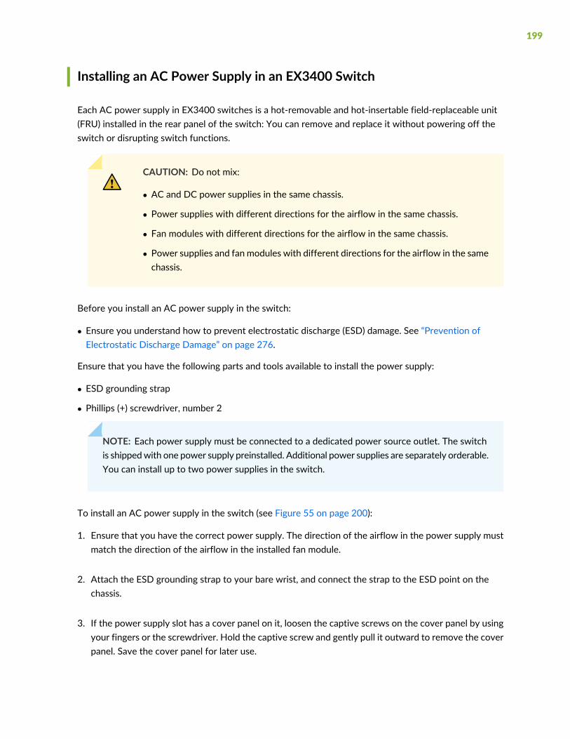
Installing an AC Power Supply in an EX3400 Switch
Each AC power supply in EX3400 switches is a hot-removable and hot-insertable field-replaceable unit(FRU) installed in the rear panel of the switch: You can remove and replace it without powering off theswitch or disrupting switch functions.
CAUTION: Do not mix:
• AC and DC power supplies in the same chassis.
• Power supplies with different directions for the airflow in the same chassis.
• Fan modules with different directions for the airflow in the same chassis.
• Power supplies and fan modules with different directions for the airflow in the samechassis.
Before you install an AC power supply in the switch:
• Ensure you understand how to prevent electrostatic discharge (ESD) damage. See “Prevention ofElectrostatic Discharge Damage” on page 276.
Ensure that you have the following parts and tools available to install the power supply:
• ESD grounding strap
• Phillips (+) screwdriver, number 2
NOTE: Each power supply must be connected to a dedicated power source outlet. The switchis shippedwith one power supply preinstalled. Additional power supplies are separately orderable.You can install up to two power supplies in the switch.
To install an AC power supply in the switch (see Figure 55 on page 200):
1. Ensure that you have the correct power supply. The direction of the airflow in the power supply mustmatch the direction of the airflow in the installed fan module.
2. Attach the ESD grounding strap to your bare wrist, and connect the strap to the ESD point on thechassis.
3. If the power supply slot has a cover panel on it, loosen the captive screws on the cover panel by usingyour fingers or the screwdriver. Hold the captive screw and gently pull it outward to remove the coverpanel. Save the cover panel for later use.
199
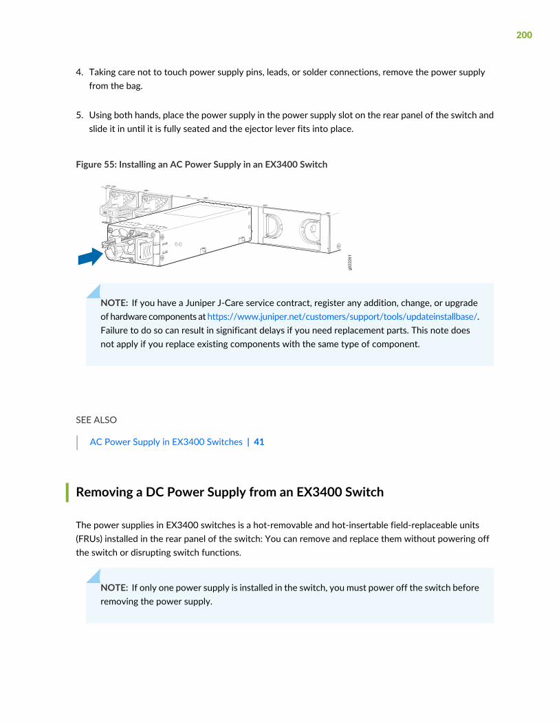
4. Taking care not to touch power supply pins, leads, or solder connections, remove the power supplyfrom the bag.
5. Using both hands, place the power supply in the power supply slot on the rear panel of the switch andslide it in until it is fully seated and the ejector lever fits into place.
Figure 55: Installing an AC Power Supply in an EX3400 Switch
g022
261
NOTE: If you have a Juniper J-Care service contract, register any addition, change, or upgradeof hardware components at https://www.juniper.net/customers/support/tools/updateinstallbase/.Failure to do so can result in significant delays if you need replacement parts. This note doesnot apply if you replace existing components with the same type of component.
SEE ALSO
AC Power Supply in EX3400 Switches | 41
Removing a DC Power Supply from an EX3400 Switch
The power supplies in EX3400 switches is a hot-removable and hot-insertable field-replaceable units(FRUs) installed in the rear panel of the switch: You can remove and replace them without powering offthe switch or disrupting switch functions.
NOTE: If only one power supply is installed in the switch, you must power off the switch beforeremoving the power supply.
200
Before you remove a power supply from an EX3400 switch, ensure that you have taken the necessaryprecautions to prevent electrostatic discharge (ESD) damage (see “Prevention of Electrostatic DischargeDamage” on page 276).
Ensure that you have the following parts and tools available to remove the power supply from the switchchassis:
• ESD grounding strap
• Phillips (+) screwdriver, number 2 (not provided)
• Slotted (-) screwdriver
• Antistatic bag or an antistatic mat
• Replacement power supply or a cover panel for the power supply slot
CAUTION: We recommend that you install either a replacement power supply or acover panel in the empty power supply slot to prevent chassis overheating and dustaccumulation.
To remove a DC power supply from the switch (see Figure 56 on page 202):
1. Place the antistatic bag or the antistatic mat on a flat, stable surface.
2. Attach the ESD grounding strap to your bare wrist, and connect the strap to the ESD point on thechassis.
3. Make sure that the voltage across the DC power source cables leads is 0 V and that there is no chancethat the cables might become active during the removal process.
4. Remove the two screws that attach the terminal connector to the power supply socket.
5. Remove the terminal connector from the power supply unit.
6. Slide the ejector lever toward the left until the power supply is unseated.
7. Grasp the power supply handle and pull firmly to slide the power supply halfway out of the chassis.
8. Taking care not to touch power supply pins, leads, or solder connections, place one hand under thepower supply to support it. Grasp the power supply handle with your other hand and pull the powersupply completely out of the chassis.
201

9. Place the power supply in the antistatic bag or on the antistatic mat placed on a flat, stable surface.
10. If you are not replacing the power supply, install the cover panel over the slot.
Figure 56: Removing a DC Power Supply from an EX3400 Switch
Installing a DC Power Supply in an EX3400 Switch
Each DC power supply in EX3400 switches is a hot-removable and hot-insertable field-replaceable unit(FRU) installed in the rear panel of the switch: You can remove and replace the power supplies withoutpowering off the switch or disrupting switch functions.
CAUTION: Do not mix:
• AC and DC power supplies in the same chassis.
• Power supplies with different directions for the airflow in the same chassis.
• Fan modules with different directions for the airflow in the same chassis.
• Power supplies and fan modules with different directions for the airflow in the samechassis.
Before you install an DC power supply in the switch:
• Ensure you understand how to prevent electrostatic discharge (ESD) damage. See “Prevention ofElectrostatic Discharge Damage” on page 276.
Ensure that you have the following parts and tools available to install the power supply:
• ESD grounding strap
• Phillips (+) screwdriver, number 2
202
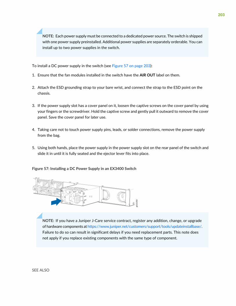
NOTE: Each power supplymust be connected to a dedicated power source. The switch is shippedwith one power supply preinstalled. Additional power supplies are separately orderable. You caninstall up to two power supplies in the switch.
To install a DC power supply in the switch (see Figure 57 on page 203):
1. Ensure that the fan modules installed in the switch have the AIR OUT label on them.
2. Attach the ESD grounding strap to your bare wrist, and connect the strap to the ESD point on thechassis.
3. If the power supply slot has a cover panel on it, loosen the captive screws on the cover panel by usingyour fingers or the screwdriver. Hold the captive screw and gently pull it outward to remove the coverpanel. Save the cover panel for later use.
4. Taking care not to touch power supply pins, leads, or solder connections, remove the power supplyfrom the bag.
5. Using both hands, place the power supply in the power supply slot on the rear panel of the switch andslide it in until it is fully seated and the ejector lever fits into place.
Figure 57: Installing a DC Power Supply in an EX3400 Switch
NOTE: If you have a Juniper J-Care service contract, register any addition, change, or upgradeof hardware components at https://www.juniper.net/customers/support/tools/updateinstallbase/.Failure to do so can result in significant delays if you need replacement parts. This note doesnot apply if you replace existing components with the same type of component.
SEE ALSO
203
DC Power Supply in EX3400 Switches | 45
Maintaining a Transceiver
IN THIS SECTION
Install a Transceiver | 204
Remove a Transceiver | 207
Install a Transceiver
The transceivers for Juniper Networks devices are hot-removable and hot-insertable field-replaceableunits (FRUs): You can remove and replace them without powering off the device or disrupting the devicefunctions.
NOTE: After you insert a transceiver or after you change the media-type configuration, wait for6 seconds for the interface to display operational commands.
NOTE: We recommend that you use only optical transceivers and optical connectors purchasedfrom Juniper Networks with your Juniper Networks device.
CAUTION: If you face a problem running a Juniper Networks device that uses athird-party optic or cable, the Juniper Networks Technical Assistance Center (JTAC)can help you diagnose the source of the problem. Your JTACengineermight recommendthat you check the third-party optic or cable and potentially replace it with an equivalentJuniper Networks optic or cable that is qualified for the device.
Before you install a transceiver in a device, ensure that you have taken the necessary precautions for safehandling of lasers (see “Laser and LED Safety Guidelines and Warnings” on page 261).
204
Ensure that you have a rubber safety cap available to cover the transceiver.
Figure 47 on page 128 shows how to install a QSFP+ transceiver. The procedure is the same for all typesof transceivers except the QSFP28 and CFP transceivers.
To install a transceiver:
CAUTION: To prevent electrostatic discharge (ESD) damage to the transceiver, donot touch the connector pins at the end of the transceiver.
1. Wrap and fasten one end of the ESD wrist strap around your bare wrist, and connect the other end ofthe strap to the ESD point on the switch.
2. Remove the transceiver from its bag.
3. Check to seewhether the transceiver is coveredwith a rubber safety cap. If it is not, cover the transceiverwith a rubber safety cap.
WARNING: Donot leave a fiber-optic transceiver uncovered exceptwhen insertingor removing a cable. The rubber safety cap keeps the port clean and preventsaccidental exposure to laser light.
4. If the port in which you want to install the transceiver is covered with a dust cover, remove the dustcover and save it in case you need to cover the port later. If you are hot-swapping a transceiver, waitfor at least 10 seconds after removing the transceiver from the port before installing a new transceiver.
5. Using both hands, carefully place the transceiver in the empty port. The connectors must face thechassis.
CAUTION: Before you slide the transceiver into the port, ensure that the transceiveris aligned correctly. Misalignment might cause the pins to bend, making thetransceiver unusable.
6. Slide the transceiver in gently until it is fully seated. If you are installing a CFP transceiver, tighten thecaptive screws on the transceiver by using your fingers.
205

7. Remove the rubber safety cap from the transceiver and the end of the cable, and insert the cable intothe transceiver.
WARNING: Do not look directly into a fiber-optic transceiver or into the ends offiber-optic cables. Fiber-optic transceivers and fiber-optic cable connected to atransceiver emit laser light that can damage your eyes.
CAUTION: Do not leave a fiber-optic transceiver uncovered except when insertingor removing cable. The safety cap keeps the port clean and prevents accidentalexposure to laser light.
8. If there is a cable management system, arrange the cable in the cable management system to preventthe cable from dislodging or developing stress points. Secure the cable so that it does not support itsown weight as it hangs to the floor. Place excess cable out of the way in a neatly coiled loop in thecable management system. Placing fasteners on the loop helps to maintain its shape.
CAUTION: Do not let fiber-optic cable hang free from the connector. Do not allowfastened loops of cable to dangle, which stresses the cable at the fastening point.
CAUTION: Avoid bending fiber-optic cable beyond its minimum bend radius. Anarc smaller than a few inches in diameter can damage the cable and cause problemsthat are difficult to diagnose.
Figure 58: Install a Transceiver
1—Ejector lever
206
Remove a Transceiver
The transceivers for Juniper Networks devices are hot-removable and hot-insertable field-replaceableunits (FRUs): You can remove and replace them without powering off the device or disrupting devicefunctions.
NOTE: After you remove a transceiver or when you change the media-type configuration, waitfor 6 seconds for the interface to display the operational commands.
Before you remove a transceiver from a device, ensure that you have taken the necessary precautions forthe safe handling of lasers (see “Laser and LED Safety Guidelines and Warnings” on page 261).
Ensure that you have the following parts and tools available:
• An antistatic bag or an antistatic mat
• Rubber safety caps to cover the transceiver and fiber-optic cable connector
• A dust cover to cover the port or a replacement transceiver
Figure 59 on page 209 shows how to remove a QSFP+ transceiver. The procedure is the same for all typesof transceivers except the QSFP28 and CFP transceivers.
To remove a transceiver from a device:
1. Place the antistatic bag or antistatic mat on a flat, stable surface.
2. Wrap and fasten one end of the ESD wrist strap around your bare wrist, and connect the other end ofthe strap to the ESD point on the switch.
3. Label the cable connected to the transceiver so that you can reconnect it correctly.
WARNING: Do not look directly into a fiber-optic transceiver or into the ends offiber-optic cables. Fiber-optic transceivers and fiber-optic cables connected totransceivers emit laser light that can damage your eyes.
WARNING: Donot leave a fiber-optic transceiver uncovered exceptwhen insertingor removing a cable. The rubber safety cap keeps the port clean and preventsaccidental exposure to laser light.
207
CAUTION: Do not bend fiber-optic cables beyond their minimum bend radius. Anarc smaller than a few inches in diameter can damage the cables and cause problemsthat are difficult to diagnose.
4. Remove the cable connected to the transceiver (see “Disconnect a Fiber-Optic Cable” on page 211).Cover the transceiver and the end of each fiber-optic cable connector with a rubber safety capimmediately after disconnecting the fiber-optic cables.
5. If there is a cable management system, arrange the cable in the cable management system to preventit from dislodging or developing stress points. Secure the cable so that it does not support its ownweight as it hangs to the floor. Place excess cable out of the way in a neatly coiled loop in the cablemanagement system. Placing fasteners on the loop helps to maintain its shape.
CAUTION: Do not bend the fiber-optic cable beyond its minimum bend radius. Anarc smaller than a few inches in diameter can damage the cable and cause problemsthat are difficult to diagnose.
208
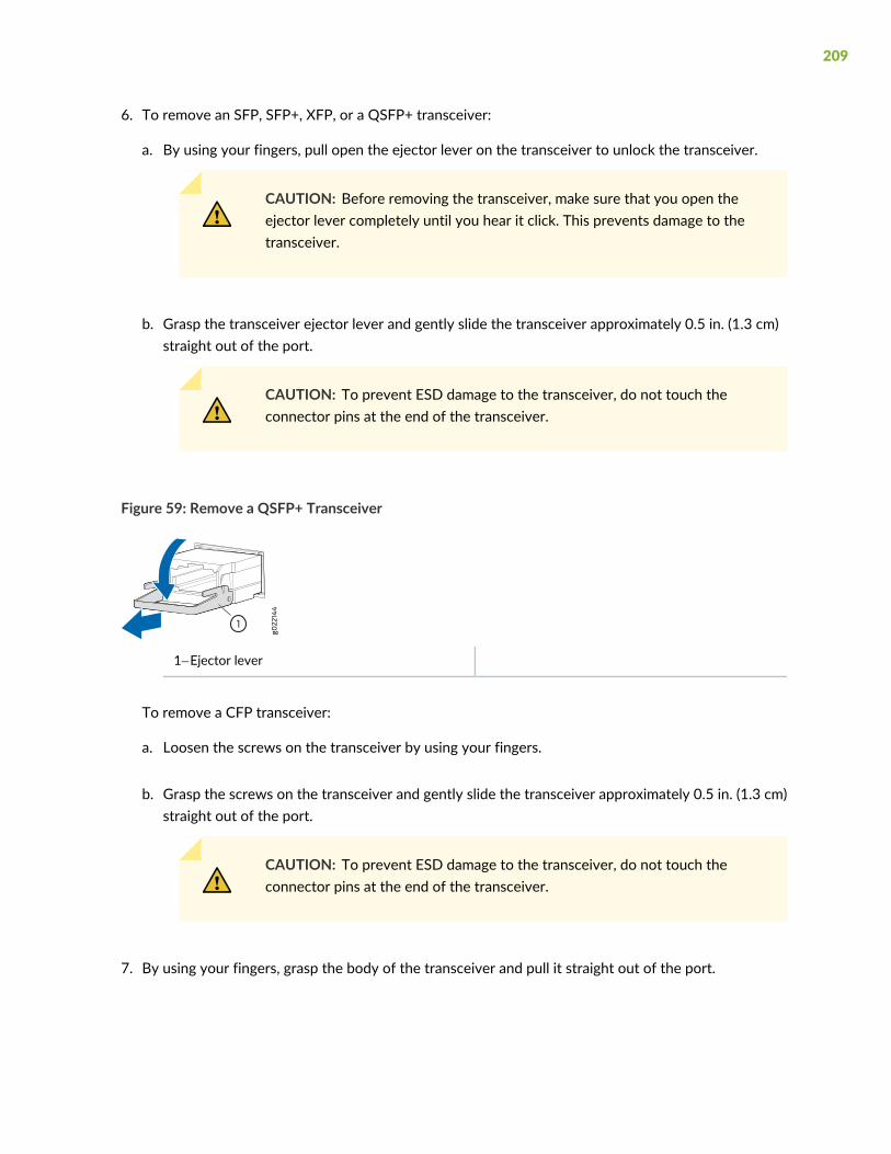
6. To remove an SFP, SFP+, XFP, or a QSFP+ transceiver:
a. By using your fingers, pull open the ejector lever on the transceiver to unlock the transceiver.
CAUTION: Before removing the transceiver, make sure that you open theejector lever completely until you hear it click. This prevents damage to thetransceiver.
b. Grasp the transceiver ejector lever and gently slide the transceiver approximately 0.5 in. (1.3 cm)straight out of the port.
CAUTION: To prevent ESD damage to the transceiver, do not touch theconnector pins at the end of the transceiver.
Figure 59: Remove a QSFP+ Transceiver
1—Ejector lever
To remove a CFP transceiver:
a. Loosen the screws on the transceiver by using your fingers.
b. Grasp the screws on the transceiver and gently slide the transceiver approximately 0.5 in. (1.3 cm)straight out of the port.
CAUTION: To prevent ESD damage to the transceiver, do not touch theconnector pins at the end of the transceiver.
7. By using your fingers, grasp the body of the transceiver and pull it straight out of the port.
209
8. Place the transceiver in the antistatic bag or on the antistatic mat placed on a flat, stable surface.
9. Place the dust cover over the empty port or install the replacement transceiver.
Maintaining Fiber-Optic Cables
IN THIS SECTION
Connect a Fiber-Optic Cable | 210
Disconnect a Fiber-Optic Cable | 211
How to Handle Fiber-Optic Cables | 212
Connect a Fiber-Optic Cable
Before you connect a fiber-optic cable to an optical transceiver installed in a device, ensure that you havetaken the necessary precautions for safe handling of lasers (see “Laser and LED Safety Guidelines andWarnings” on page 261).
To connect a fiber-optic cable to an optical transceiver installed in a device:
WARNING: Do not look directly into a fiber-optic transceiver or into the ends offiber-optic cables. Fiber-optic transceivers and fiber-optic cables connected totransceivers emit laser light that can damage your eyes.
1. If the fiber-optic cable connector is covered with a rubber safety cap, remove the cap. Save the cap.
2. Remove the rubber safety cap from the optical transceiver. Save the cap.
3. Insert the cable connector into the optical transceiver (see Figure 48 on page 129).
210
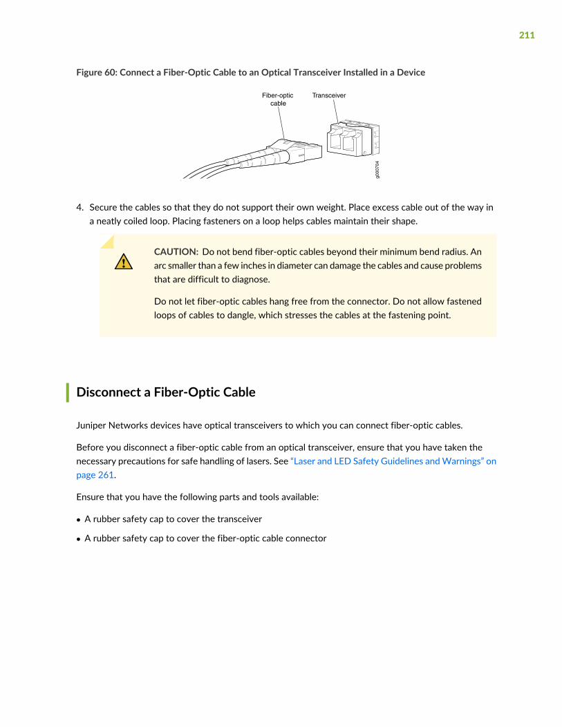
Figure 60: Connect a Fiber-Optic Cable to an Optical Transceiver Installed in a Device
g000
704
TransceiverFiber-opticcable
4. Secure the cables so that they do not support their own weight. Place excess cable out of the way ina neatly coiled loop. Placing fasteners on a loop helps cables maintain their shape.
CAUTION: Do not bend fiber-optic cables beyond their minimum bend radius. Anarc smaller than a few inches in diameter can damage the cables and cause problemsthat are difficult to diagnose.
Do not let fiber-optic cables hang free from the connector. Do not allow fastenedloops of cables to dangle, which stresses the cables at the fastening point.
Disconnect a Fiber-Optic Cable
Juniper Networks devices have optical transceivers to which you can connect fiber-optic cables.
Before you disconnect a fiber-optic cable from an optical transceiver, ensure that you have taken thenecessary precautions for safe handling of lasers. See “Laser and LED Safety Guidelines andWarnings” onpage 261.
Ensure that you have the following parts and tools available:
• A rubber safety cap to cover the transceiver
• A rubber safety cap to cover the fiber-optic cable connector
211
To disconnect a fiber-optic cable from an optical transceiver installed in the device:
1. Disable the port in which the transceiver is installed by issuing the following command:
[edit interfaces]
user@device# set interface-name disable
WARNING: Do not look directly into a fiber-optic transceiver or into the ends offiber-optic cables. Fiber-optic transceivers and fiber-optic cables connected totransceivers emit laser light that can damage your eyes.
2. Carefully unplug the fiber-optic cable connector from the transceiver.
3. Cover the transceiver with a rubber safety cap.
WARNING: Donot leave a fiber-optic transceiver uncovered exceptwhen insertingor removing a cable. The rubber safety cap keeps the port clean and preventsaccidental exposure to laser light.
4. Cover the fiber-optic cable connector with the rubber safety cap.
How to Handle Fiber-Optic Cables
Fiber-optic cables connect to optical transceivers that are installed in Juniper Networks devices.
To maintain fiber-optic cables:
• When you unplug a fiber-optic cable from a transceiver, place rubber safety caps over the transceiverand on the end of the cable.
• Anchor fiber-optic cables to prevent stress on the connectors. When attaching a fiber-optic cable to atransceiver, be sure to secure the fiber-optic cable so that it does not support its own weight as it hangsto the floor. Never let a fiber-optic cable hang free from the connector.
• Avoid bending fiber-optic cables beyond their minimum bend radius. Bending fiber-optic cables intoarcs smaller than a few inches in diameter can damage the cables and cause problems that are difficultto diagnose.
212

• Frequent plugging and unplugging of fiber-optic cables in and out of optical instruments can damagethe instruments, which are expensive to repair. Attach a short fiber extension to the optical equipment.Anywear and tear due to frequent plugging and unplugging is then absorbed by the short fiber extension,which is easier and less expensive to replace than the instruments.
• Keep fiber-optic cable connections clean. Microdeposits of oil and dust in the canal of the transceiveror cable connector can cause loss of light, reduction in signal power, and possibly intermittent problemswith the optical connection.
• To clean the transceiver canal, use an appropriate fiber-cleaning device such as RIFOCS Fiber OpticAdaptor Cleaning Wands (part number 946). Follow the instructions in the cleaning kit you use.
• After cleaning the transceiver, make sure that the connector tip of the fiber-optic cable is clean. Useonly an approved alcohol-free fiber-optic cable cleaning kit such as theOpptex Cletop-S
®
Fiber Cleaner.Follow the instructions in the cleaning kit you use.
213

5CHAPTER
Troubleshooting Hardware
Troubleshooting EX3400 Components | 215
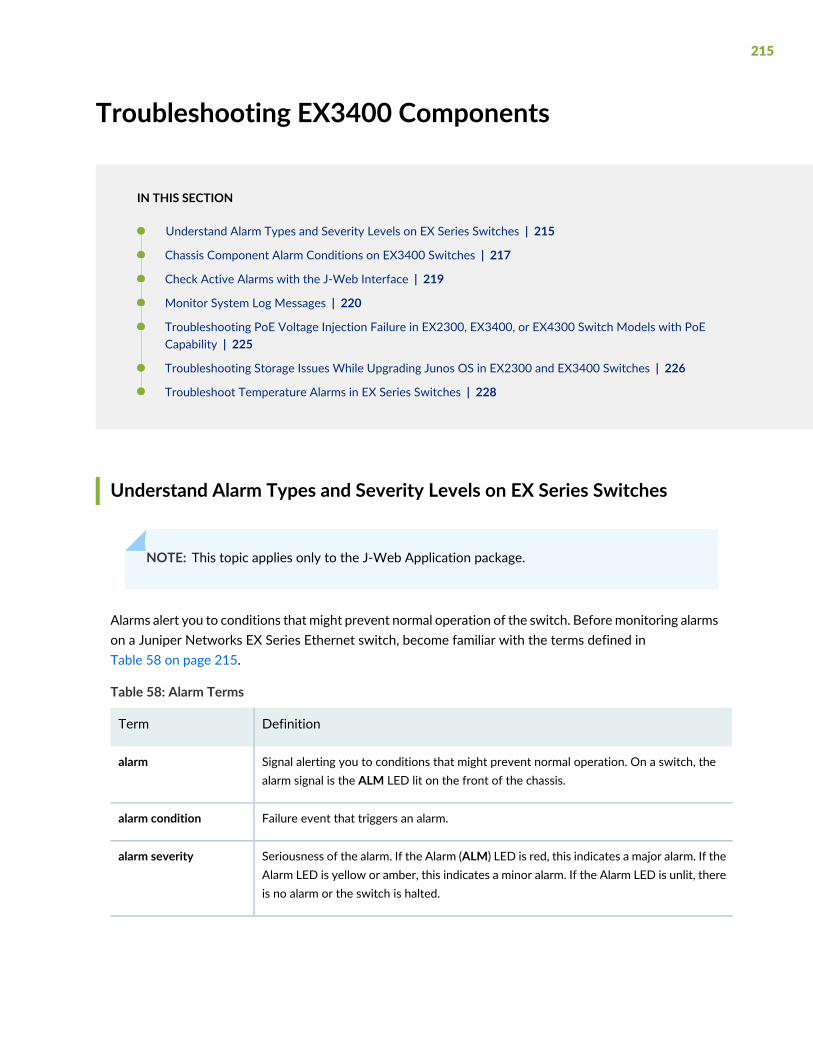
Troubleshooting EX3400 Components
IN THIS SECTION
Understand Alarm Types and Severity Levels on EX Series Switches | 215
Chassis Component Alarm Conditions on EX3400 Switches | 217
Check Active Alarms with the J-Web Interface | 219
Monitor System Log Messages | 220
Troubleshooting PoE Voltage Injection Failure in EX2300, EX3400, or EX4300 Switch Models with PoECapability | 225
Troubleshooting Storage Issues While Upgrading Junos OS in EX2300 and EX3400 Switches | 226
Troubleshoot Temperature Alarms in EX Series Switches | 228
Understand Alarm Types and Severity Levels on EX Series Switches
NOTE: This topic applies only to the J-Web Application package.
Alarms alert you to conditions that might prevent normal operation of the switch. Beforemonitoring alarmson a Juniper Networks EX Series Ethernet switch, become familiar with the terms defined inTable 58 on page 215.
Table 58: Alarm Terms
DefinitionTerm
Signal alerting you to conditions that might prevent normal operation. On a switch, thealarm signal is the ALM LED lit on the front of the chassis.
alarm
Failure event that triggers an alarm.alarm condition
Seriousness of the alarm. If the Alarm (ALM) LED is red, this indicates a major alarm. If theAlarm LED is yellow or amber, this indicates a minor alarm. If the Alarm LED is unlit, thereis no alarm or the switch is halted.
alarm severity
215
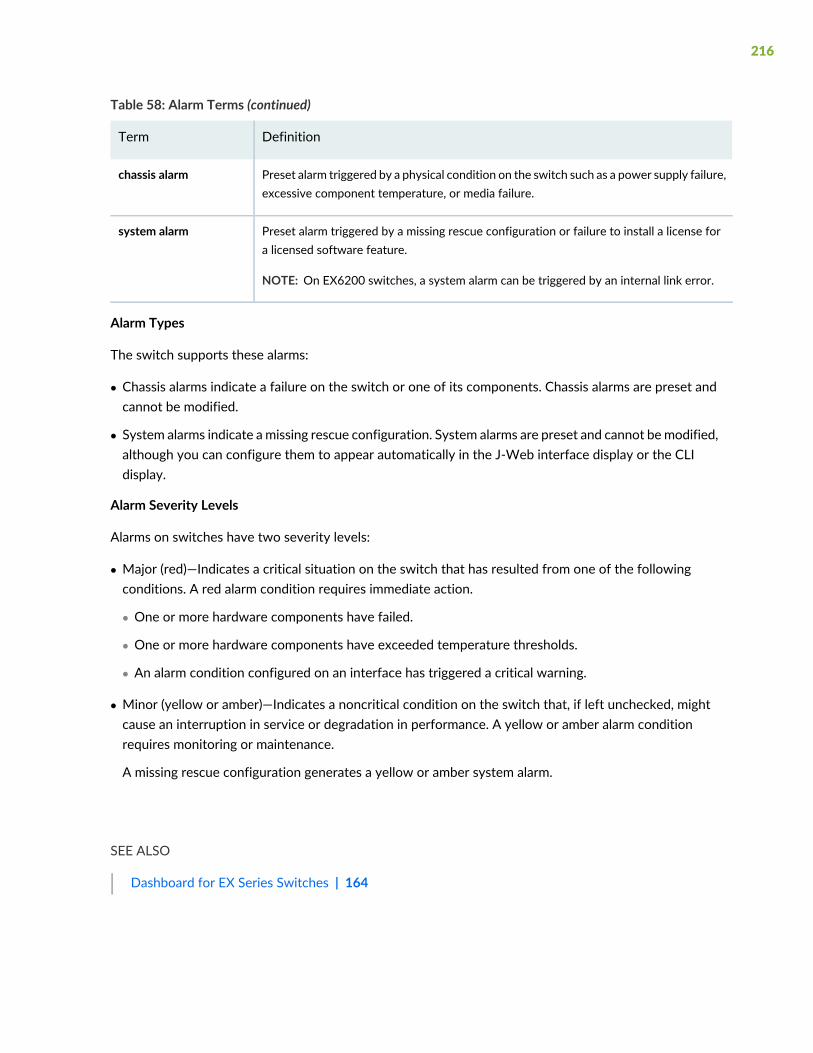
Table 58: Alarm Terms (continued)
DefinitionTerm
Preset alarm triggered by a physical condition on the switch such as a power supply failure,excessive component temperature, or media failure.
chassis alarm
Preset alarm triggered by a missing rescue configuration or failure to install a license fora licensed software feature.
NOTE: On EX6200 switches, a system alarm can be triggered by an internal link error.
system alarm
Alarm Types
The switch supports these alarms:
• Chassis alarms indicate a failure on the switch or one of its components. Chassis alarms are preset andcannot be modified.
• System alarms indicate a missing rescue configuration. System alarms are preset and cannot bemodified,although you can configure them to appear automatically in the J-Web interface display or the CLIdisplay.
Alarm Severity Levels
Alarms on switches have two severity levels:
• Major (red)—Indicates a critical situation on the switch that has resulted from one of the followingconditions. A red alarm condition requires immediate action.
• One or more hardware components have failed.
• One or more hardware components have exceeded temperature thresholds.
• An alarm condition configured on an interface has triggered a critical warning.
• Minor (yellow or amber)—Indicates a noncritical condition on the switch that, if left unchecked, mightcause an interruption in service or degradation in performance. A yellow or amber alarm conditionrequires monitoring or maintenance.
A missing rescue configuration generates a yellow or amber system alarm.
SEE ALSO
Dashboard for EX Series Switches | 164
216
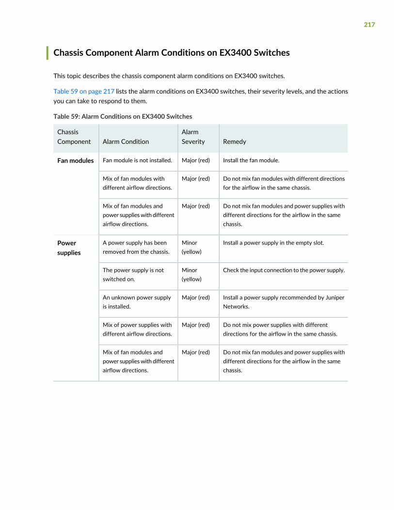
Chassis Component Alarm Conditions on EX3400 Switches
This topic describes the chassis component alarm conditions on EX3400 switches.
Table 59 on page 217 lists the alarm conditions on EX3400 switches, their severity levels, and the actionsyou can take to respond to them.
Table 59: Alarm Conditions on EX3400 Switches
RemedyAlarmSeverityAlarm Condition
ChassisComponent
Install the fan module.Major (red)Fan module is not installed.Fan modules
Do not mix fan modules with different directionsfor the airflow in the same chassis.
Major (red)Mix of fan modules withdifferent airflow directions.
Do not mix fan modules and power supplies withdifferent directions for the airflow in the samechassis.
Major (red)Mix of fan modules andpower supplieswith differentairflow directions.
Install a power supply in the empty slot.Minor(yellow)
A power supply has beenremoved from the chassis.
Powersupplies
Check the input connection to the power supply.Minor(yellow)
The power supply is notswitched on.
Install a power supply recommended by JuniperNetworks.
Major (red)An unknown power supplyis installed.
Do not mix power supplies with differentdirections for the airflow in the same chassis.
Major (red)Mix of power supplies withdifferent airflow directions.
Do not mix fan modules and power supplies withdifferent directions for the airflow in the samechassis.
Major (red)Mix of fan modules andpower supplieswith differentairflow directions.
217
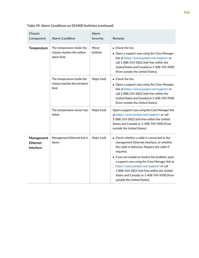
Table 59: Alarm Conditions on EX3400 Switches (continued)
RemedyAlarmSeverityAlarm Condition
ChassisComponent
• Check the fan.
• Open a support case using the Case Managerlink at https://www.juniper.net/support/ orcall 1-888-314-5822 (toll-free within theUnited States and Canada) or 1-408-745-9500(from outside the United States).
Minor(yellow)
The temperature inside thechassis reaches the yellowalarm limit.
Temperature
• Check the fan.
• Open a support case using the Case Managerlink at https://www.juniper.net/support/ orcall 1-888-314-5822 (toll-free within theUnited States and Canada) or 1-408-745-9500(from outside the United States).
Major (red)The temperature inside thechassis reaches the red alarmlimit.
Open a support case using the CaseManager linkat https://www.juniper.net/support/ or call1-888-314-5822 (toll-free within the UnitedStates and Canada) or 1-408-745-9500 (fromoutside the United States).
Major (red)The temperature sensor hasfailed.
• Check whether a cable is connected to themanagement Ethernet interface, or whetherthe cable is defective. Replace the cable ifrequired.
• If you are unable to resolve the problem, opena support case using the Case Manager link athttps://www.juniper.net/support/ or call1-888-314-5822 (toll-free within the UnitedStates and Canada) or 1-408-745-9500 (fromoutside the United States).
Major (red)Management Ethernet link isdown.
ManagementEthernetinterface
218
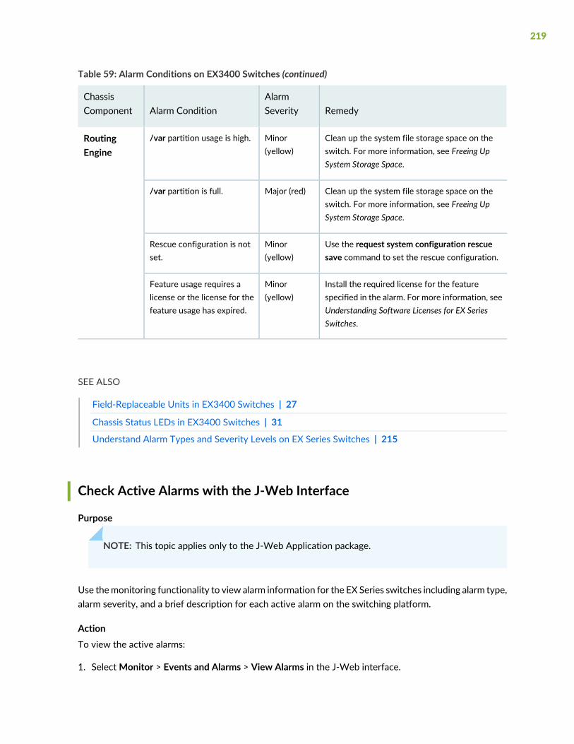
Table 59: Alarm Conditions on EX3400 Switches (continued)
RemedyAlarmSeverityAlarm Condition
ChassisComponent
Clean up the system file storage space on theswitch. For more information, see Freeing UpSystem Storage Space.
Minor(yellow)
/var partition usage is high.RoutingEngine
Clean up the system file storage space on theswitch. For more information, see Freeing UpSystem Storage Space.
Major (red)/var partition is full.
Use the request system configuration rescuesave command to set the rescue configuration.
Minor(yellow)
Rescue configuration is notset.
Install the required license for the featurespecified in the alarm. For more information, seeUnderstanding Software Licenses for EX SeriesSwitches.
Minor(yellow)
Feature usage requires alicense or the license for thefeature usage has expired.
SEE ALSO
Field-Replaceable Units in EX3400 Switches | 27
Chassis Status LEDs in EX3400 Switches | 31
Understand Alarm Types and Severity Levels on EX Series Switches | 215
Check Active Alarms with the J-Web Interface
Purpose
NOTE: This topic applies only to the J-Web Application package.
Use themonitoring functionality to view alarm information for the EX Series switches including alarm type,alarm severity, and a brief description for each active alarm on the switching platform.
ActionTo view the active alarms:
1. SelectMonitor > Events and Alarms > View Alarms in the J-Web interface.
219
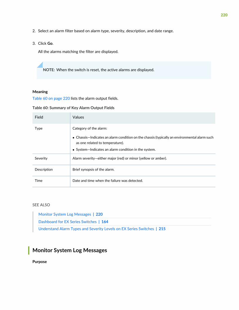
2. Select an alarm filter based on alarm type, severity, description, and date range.
3. Click Go.
All the alarms matching the filter are displayed.
NOTE: When the switch is reset, the active alarms are displayed.
MeaningTable 60 on page 220 lists the alarm output fields.
Table 60: Summary of Key Alarm Output Fields
ValuesField
Category of the alarm:
• Chassis—Indicates an alarm condition on the chassis (typically an environmental alarm suchas one related to temperature).
• System—Indicates an alarm condition in the system.
Type
Alarm severity—either major (red) or minor (yellow or amber).Severity
Brief synopsis of the alarm.Description
Date and time when the failure was detected.Time
SEE ALSO
Monitor System Log Messages | 220
Dashboard for EX Series Switches | 164
Understand Alarm Types and Severity Levels on EX Series Switches | 215
Monitor System Log Messages
Purpose
220
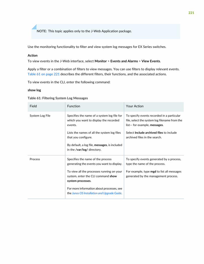
NOTE: This topic applies only to the J-Web Application package.
Use the monitoring functionality to filter and view system log messages for EX Series switches.
ActionTo view events in the J-Web interface, selectMonitor > Events and Alarms > View Events.
Apply a filter or a combination of filters to view messages. You can use filters to display relevant events.Table 61 on page 221 describes the different filters, their functions, and the associated actions.
To view events in the CLI, enter the following command:
show log
Table 61: Filtering System Log Messages
Your ActionFunctionField
To specify events recorded in a particularfile, select the system log filename from thelist— for example, messages.
Select Include archived files to includearchived files in the search.
Specifies the name of a system log file forwhich you want to display the recordedevents.
Lists the names of all the system log filesthat you configure.
By default, a log file,messages, is includedin the /var/log/ directory.
System Log File
To specify events generated by a process,type the name of the process.
For example, type mgd to list all messagesgenerated by the management process.
Specifies the name of the processgenerating the events you want to display.
To view all the processes running on yoursystem, enter the CLI command showsystem processes.
For more information about processes, seethe JunosOS Installation andUpgradeGuide.
Process
221
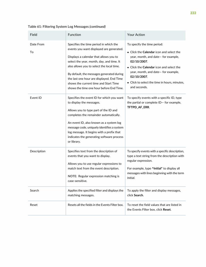
Table 61: Filtering System Log Messages (continued)
Your ActionFunctionField
To specify the time period:
• Click the Calendar icon and select theyear, month, and date— for example,02/10/2007.
• Click the Calendar icon and select theyear, month, and date— for example,02/10/2007.
• Click to select the time in hours, minutes,and seconds.
Specifies the time period in which theevents you want displayed are generated.
Displays a calendar that allows you toselect the year, month, day, and time. Italso allows you to select the local time.
By default, themessages generated duringthe last one hour are displayed. End Timeshows the current time and Start Timeshows the time one hour before End Time.
Date From
To
To specify events with a specific ID, typethe partial or complete ID— for example,TFTPD_AF_ERR.
Specifies the event ID for which you wantto display the messages.
Allows you to type part of the ID andcompletes the remainder automatically.
An event ID, also known as a system logmessage code, uniquely identifies a systemlog message. It begins with a prefix thatindicates the generating software processor library.
Event ID
To specify eventswith a specific description,type a text string from the description withregular expression.
For example, type ^Initial* to display allmessageswith lines beginningwith the termInitial.
Specifies text from the description ofevents that you want to display.
Allows you to use regular expressions tomatch text from the event description.
NOTE: Regular expression matching iscase-sensitive.
Description
To apply the filter and display messages,click Search.
Applies the specified filter and displays thematching messages.
Search
To reset the field values that are listed inthe Events Filter box, click Reset.
Resets all the fields in the Events Filter box.Reset
222
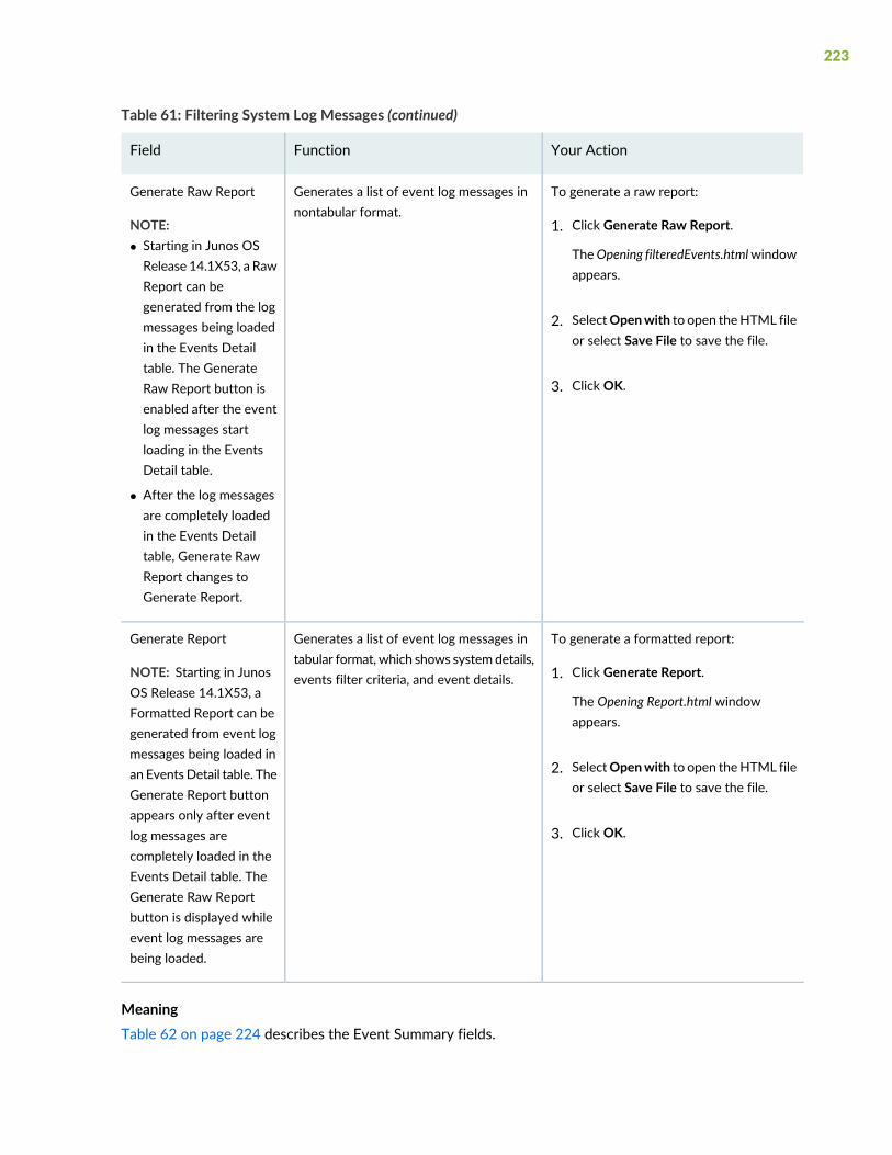
Table 61: Filtering System Log Messages (continued)
Your ActionFunctionField
To generate a raw report:
1. Click Generate Raw Report.
TheOpening filteredEvents.htmlwindowappears.
2. SelectOpenwith to open theHTML fileor select Save File to save the file.
3. Click OK.
Generates a list of event log messages innontabular format.
Generate Raw Report
NOTE:• Starting in Junos OSRelease 14.1X53, a RawReport can begenerated from the logmessages being loadedin the Events Detailtable. The GenerateRaw Report button isenabled after the eventlog messages startloading in the EventsDetail table.
• After the log messagesare completely loadedin the Events Detailtable, Generate RawReport changes toGenerate Report.
To generate a formatted report:
1. Click Generate Report.
The Opening Report.html windowappears.
2. SelectOpenwith to open theHTML fileor select Save File to save the file.
3. Click OK.
Generates a list of event log messages intabular format, which shows systemdetails,events filter criteria, and event details.
Generate Report
NOTE: Starting in JunosOS Release 14.1X53, aFormatted Report can begenerated from event logmessages being loaded inan EventsDetail table. TheGenerate Report buttonappears only after eventlog messages arecompletely loaded in theEvents Detail table. TheGenerate Raw Reportbutton is displayed whileevent log messages arebeing loaded.
MeaningTable 62 on page 224 describes the Event Summary fields.
223
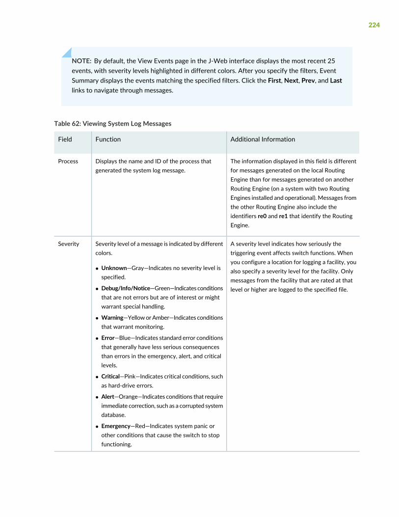
NOTE: By default, the View Events page in the J-Web interface displays the most recent 25events, with severity levels highlighted in different colors. After you specify the filters, EventSummary displays the events matching the specified filters. Click the First, Next, Prev, and Lastlinks to navigate through messages.
Table 62: Viewing System Log Messages
Additional InformationFunctionField
The information displayed in this field is differentfor messages generated on the local RoutingEngine than for messages generated on anotherRouting Engine (on a system with two RoutingEngines installed and operational). Messages fromthe other Routing Engine also include theidentifiers re0 and re1 that identify the RoutingEngine.
Displays the name and ID of the process thatgenerated the system log message.
Process
A severity level indicates how seriously thetriggering event affects switch functions. Whenyou configure a location for logging a facility, youalso specify a severity level for the facility. Onlymessages from the facility that are rated at thatlevel or higher are logged to the specified file.
Severity level of amessage is indicated by differentcolors.
• Unknown—Gray—Indicates no severity level isspecified.
• Debug/Info/Notice—Green—Indicates conditionsthat are not errors but are of interest or mightwarrant special handling.
• Warning—YelloworAmber—Indicates conditionsthat warrant monitoring.
• Error—Blue—Indicates standard error conditionsthat generally have less serious consequencesthan errors in the emergency, alert, and criticallevels.
• Critical—Pink—Indicates critical conditions, suchas hard-drive errors.
• Alert—Orange—Indicates conditions that requireimmediate correction, such as a corrupted systemdatabase.
• Emergency—Red—Indicates system panic orother conditions that cause the switch to stopfunctioning.
Severity
224
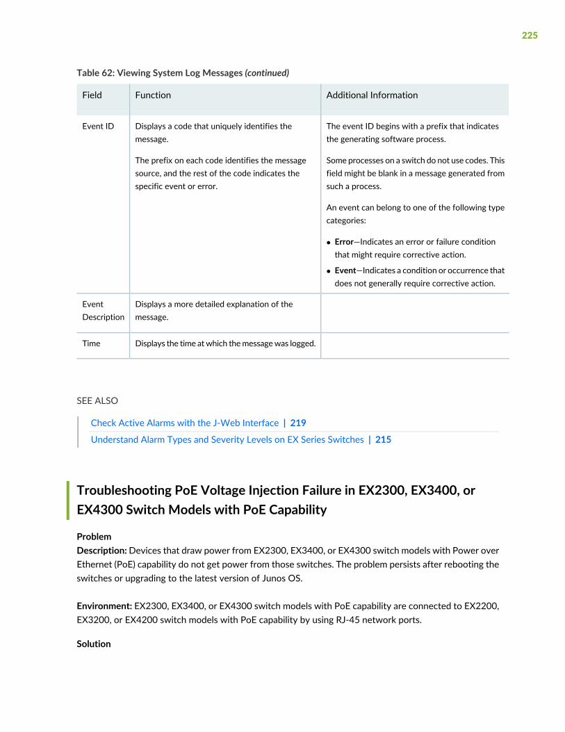
Table 62: Viewing System Log Messages (continued)
Additional InformationFunctionField
The event ID begins with a prefix that indicatesthe generating software process.
Some processes on a switch do not use codes. Thisfield might be blank in a message generated fromsuch a process.
An event can belong to one of the following typecategories:
• Error—Indicates an error or failure conditionthat might require corrective action.
• Event—Indicates a condition or occurrence thatdoes not generally require corrective action.
Displays a code that uniquely identifies themessage.
The prefix on each code identifies the messagesource, and the rest of the code indicates thespecific event or error.
Event ID
Displays a more detailed explanation of themessage.
EventDescription
Displays the time atwhich themessagewas logged.Time
SEE ALSO
Check Active Alarms with the J-Web Interface | 219
Understand Alarm Types and Severity Levels on EX Series Switches | 215
Troubleshooting PoE Voltage Injection Failure in EX2300, EX3400, orEX4300 Switch Models with PoE Capability
ProblemDescription:Devices that draw power from EX2300, EX3400, or EX4300 switch models with Power overEthernet (PoE) capability do not get power from those switches. The problem persists after rebooting theswitches or upgrading to the latest version of Junos OS.
Environment: EX2300, EX3400, or EX4300 switch models with PoE capability are connected to EX2200,EX3200, or EX4200 switch models with PoE capability by using RJ-45 network ports.
Solution
225
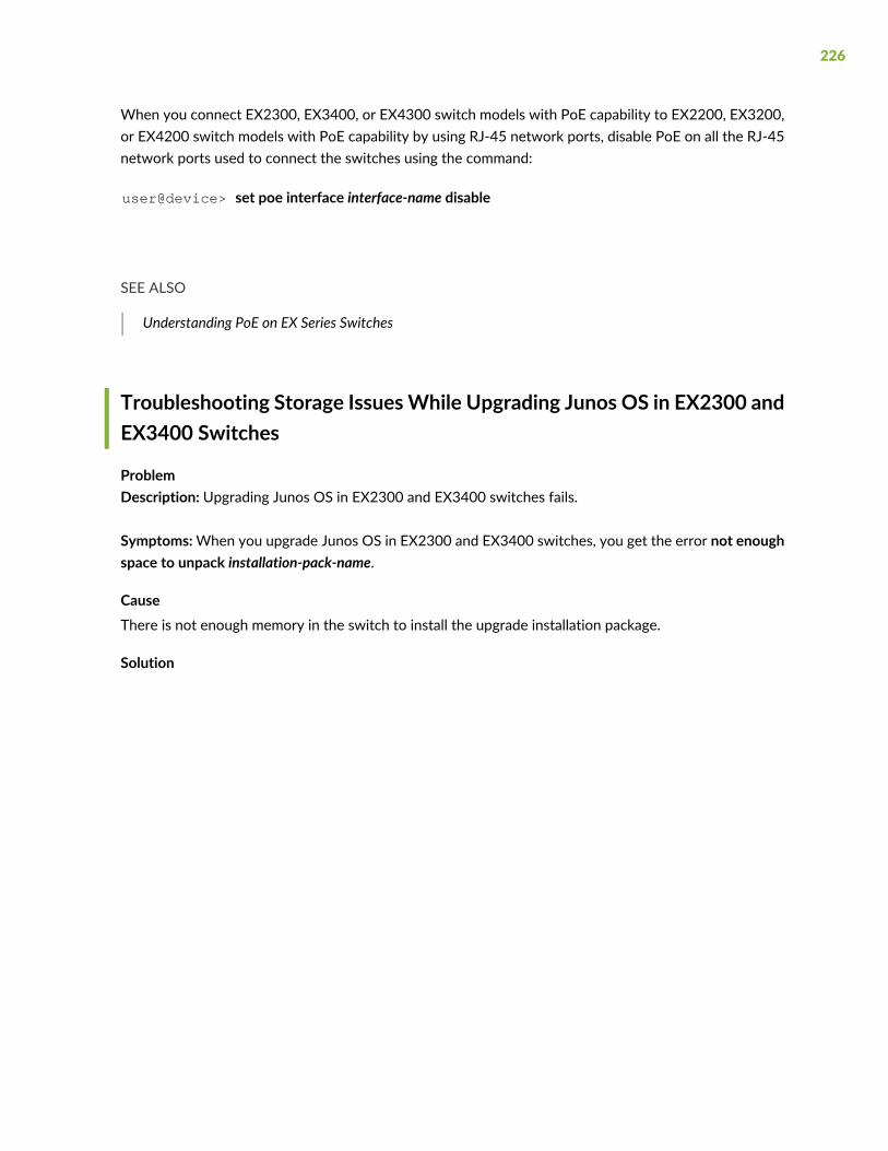
When you connect EX2300, EX3400, or EX4300 switch models with PoE capability to EX2200, EX3200,or EX4200 switch models with PoE capability by using RJ-45 network ports, disable PoE on all the RJ-45network ports used to connect the switches using the command:
user@device> set poe interface interface-name disable
SEE ALSO
Understanding PoE on EX Series Switches
Troubleshooting Storage IssuesWhile Upgrading Junos OS in EX2300 andEX3400 Switches
ProblemDescription: Upgrading Junos OS in EX2300 and EX3400 switches fails.
Symptoms:When you upgrade Junos OS in EX2300 and EX3400 switches, you get the error not enoughspace to unpack installation-pack-name.
CauseThere is not enough memory in the switch to install the upgrade installation package.
Solution
226
If upgrading Junos OS in EX2300 and EX3400 switches fails due to the lack of memory in the switch:
1. Perform a system storage cleanup and delete unwanted files in the system storage by using thecommand:
user@switch> request system storage cleanup
NOTE:
You can get the list of files that this command deletes by using the command:
user@switch> request system storage cleanup dry-run
This command does not delete files in the root folder; it deletes files in the folders jail, log,and tmp only.
2. If any directory is taking up a lot of memory, delete unwanted files in that directory. Check the memoryutilization by using the command:
user@switch> show system storage
3. Delete non-recovery snapshots.
• If Junos OS 15.1X53D56 or later is installed in your switch:
a. Delete non-recovery snapshots by using the command:
user@switch> request system software add software-image-name force
• If a version of Junos OS released earlier than Junos OS 15.1X53D56 is installed in your switch:
a. Check for non-recovery snapshots by using the command:
user@switch> show system snapshot
b.NOTE: Snapshot names are not completed automatically in the CLI; youmust enter thesnapshot name.
Delete non-recovery snapshots by using the command:
227

user@switch> request system snapshot delete snapshot-name
4. After upgrading Junos OS, delete the upgrade installation package by using the command:
user@switch> request system software add software-image-name force unlink
SEE ALSO
Understanding Software Installation on EX Series Switches
Troubleshoot Temperature Alarms in EX Series Switches
ProblemDescription: EX Series switches generate a temperature alarm FPC 0 EX-PFE1 Temp Too Hot.
CauseTemperature sensors in the chassis monitor the temperature of the chassis. The switch raises an alarm ifa fan fails or if the temperature of the chassis exceeds permissible levels.
SolutionWhen the switch raises a temperature alarm such as the FPC 0 EX-PFE1 Temp Too Hot alarm, use theshow chassis environment and the show chassis temperature-thresholds commands to identify thecondition that triggered the alarm.
CAUTION: To prevent the switch from overheating, do not operate it in an area thatexceeds the maximum recommended ambient temperature. To prevent airflowrestriction, allow at least 6 inches (15.2 cm) of clearance around the ventilationopenings.
1. Connect to the switch by using Telnet and issue the showchassis environment command. This commanddisplays environmental information about the switch chassis, including the temperature, and informationabout the fans, power supplies, and Routing Engines. Following is a sample output on an EX9208 switch.The output is similar on other EX Series switches.
user@switch> show chassis environment
Class Item Status Measurement
Temp PEM 0 OK 40 degrees C / 104 degrees F
228
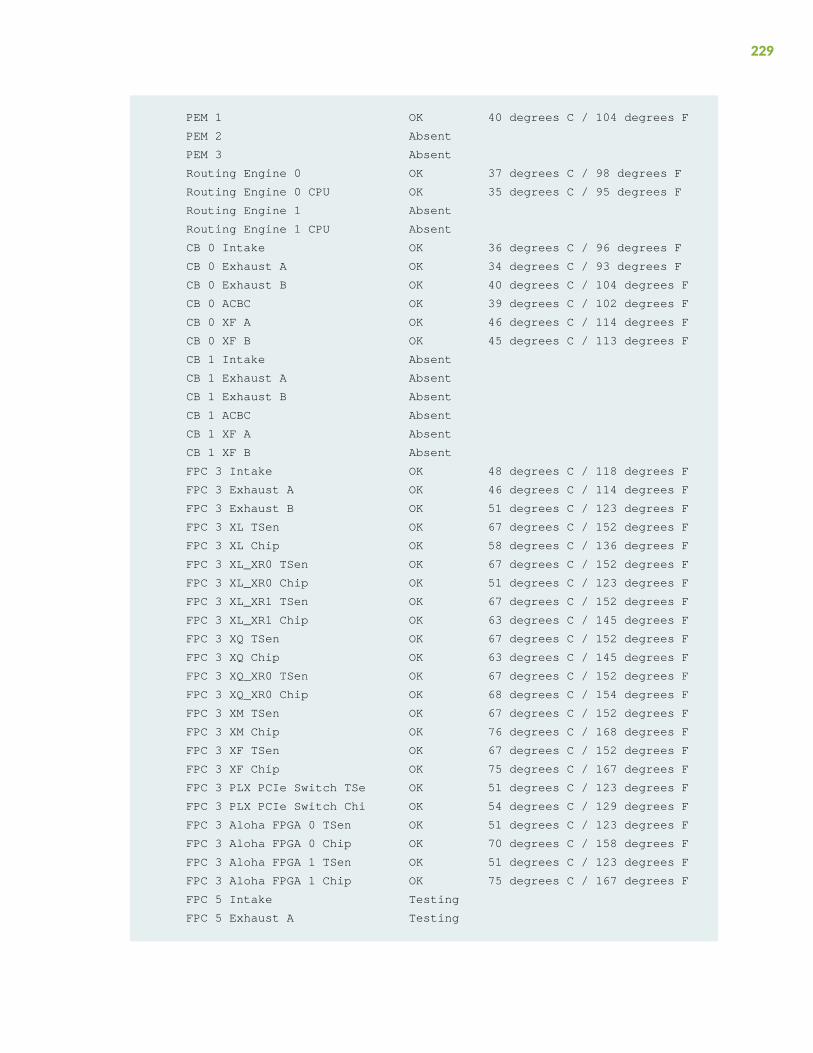
PEM 1 OK 40 degrees C / 104 degrees F
PEM 2 Absent
PEM 3 Absent
Routing Engine 0 OK 37 degrees C / 98 degrees F
Routing Engine 0 CPU OK 35 degrees C / 95 degrees F
Routing Engine 1 Absent
Routing Engine 1 CPU Absent
CB 0 Intake OK 36 degrees C / 96 degrees F
CB 0 Exhaust A OK 34 degrees C / 93 degrees F
CB 0 Exhaust B OK 40 degrees C / 104 degrees F
CB 0 ACBC OK 39 degrees C / 102 degrees F
CB 0 XF A OK 46 degrees C / 114 degrees F
CB 0 XF B OK 45 degrees C / 113 degrees F
CB 1 Intake Absent
CB 1 Exhaust A Absent
CB 1 Exhaust B Absent
CB 1 ACBC Absent
CB 1 XF A Absent
CB 1 XF B Absent
FPC 3 Intake OK 48 degrees C / 118 degrees F
FPC 3 Exhaust A OK 46 degrees C / 114 degrees F
FPC 3 Exhaust B OK 51 degrees C / 123 degrees F
FPC 3 XL TSen OK 67 degrees C / 152 degrees F
FPC 3 XL Chip OK 58 degrees C / 136 degrees F
FPC 3 XL_XR0 TSen OK 67 degrees C / 152 degrees F
FPC 3 XL_XR0 Chip OK 51 degrees C / 123 degrees F
FPC 3 XL_XR1 TSen OK 67 degrees C / 152 degrees F
FPC 3 XL_XR1 Chip OK 63 degrees C / 145 degrees F
FPC 3 XQ TSen OK 67 degrees C / 152 degrees F
FPC 3 XQ Chip OK 63 degrees C / 145 degrees F
FPC 3 XQ_XR0 TSen OK 67 degrees C / 152 degrees F
FPC 3 XQ_XR0 Chip OK 68 degrees C / 154 degrees F
FPC 3 XM TSen OK 67 degrees C / 152 degrees F
FPC 3 XM Chip OK 76 degrees C / 168 degrees F
FPC 3 XF TSen OK 67 degrees C / 152 degrees F
FPC 3 XF Chip OK 75 degrees C / 167 degrees F
FPC 3 PLX PCIe Switch TSe OK 51 degrees C / 123 degrees F
FPC 3 PLX PCIe Switch Chi OK 54 degrees C / 129 degrees F
FPC 3 Aloha FPGA 0 TSen OK 51 degrees C / 123 degrees F
FPC 3 Aloha FPGA 0 Chip OK 70 degrees C / 158 degrees F
FPC 3 Aloha FPGA 1 TSen OK 51 degrees C / 123 degrees F
FPC 3 Aloha FPGA 1 Chip OK 75 degrees C / 167 degrees F
FPC 5 Intake Testing
FPC 5 Exhaust A Testing
229
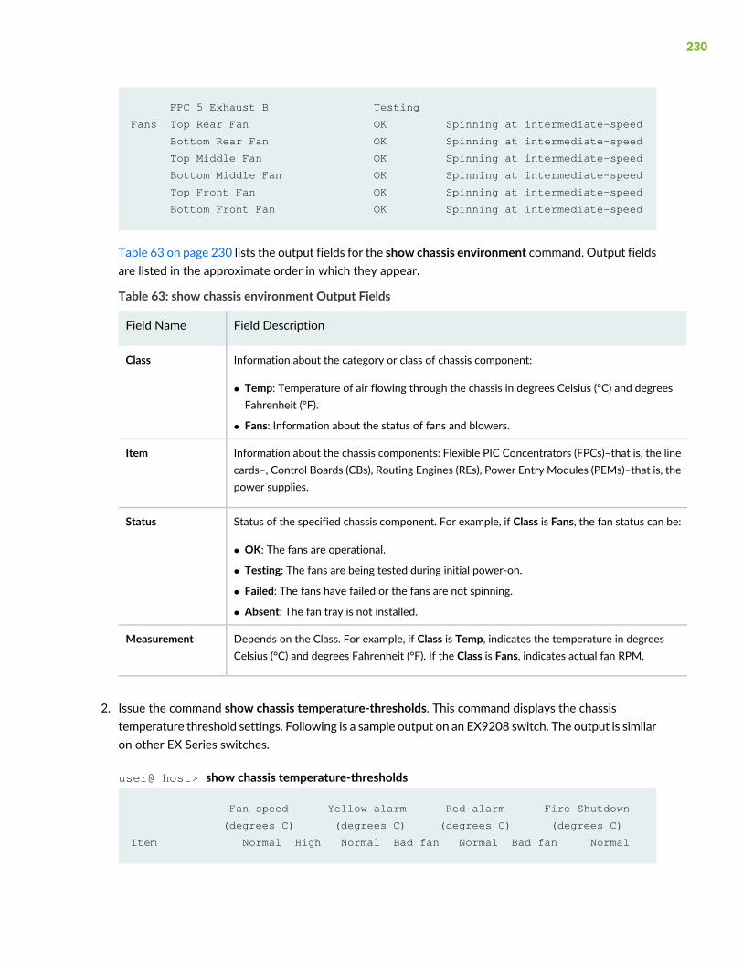
FPC 5 Exhaust B Testing
Fans Top Rear Fan OK Spinning at intermediate-speed
Bottom Rear Fan OK Spinning at intermediate-speed
Top Middle Fan OK Spinning at intermediate-speed
Bottom Middle Fan OK Spinning at intermediate-speed
Top Front Fan OK Spinning at intermediate-speed
Bottom Front Fan OK Spinning at intermediate-speed
Table 63 on page 230 lists the output fields for the show chassis environment command. Output fieldsare listed in the approximate order in which they appear.
Table 63: show chassis environment Output Fields
Field DescriptionField Name
Information about the category or class of chassis component:
• Temp: Temperature of air flowing through the chassis in degrees Celsius (°C) and degreesFahrenheit (°F).
• Fans: Information about the status of fans and blowers.
Class
Information about the chassis components: Flexible PIC Concentrators (FPCs)–that is, the linecards–, Control Boards (CBs), Routing Engines (REs), Power Entry Modules (PEMs)–that is, thepower supplies.
Item
Status of the specified chassis component. For example, if Class is Fans, the fan status can be:
• OK: The fans are operational.
• Testing: The fans are being tested during initial power-on.
• Failed: The fans have failed or the fans are not spinning.
• Absent: The fan tray is not installed.
Status
Depends on the Class. For example, if Class is Temp, indicates the temperature in degreesCelsius (°C) and degrees Fahrenheit (°F). If the Class is Fans, indicates actual fan RPM.
Measurement
2. Issue the command show chassis temperature-thresholds. This command displays the chassistemperature threshold settings. Following is a sample output on an EX9208 switch. The output is similaron other EX Series switches.
user@ host> show chassis temperature-thresholds
Fan speed Yellow alarm Red alarm Fire Shutdown
(degrees C) (degrees C) (degrees C) (degrees C)
Item Normal High Normal Bad fan Normal Bad fan Normal
230
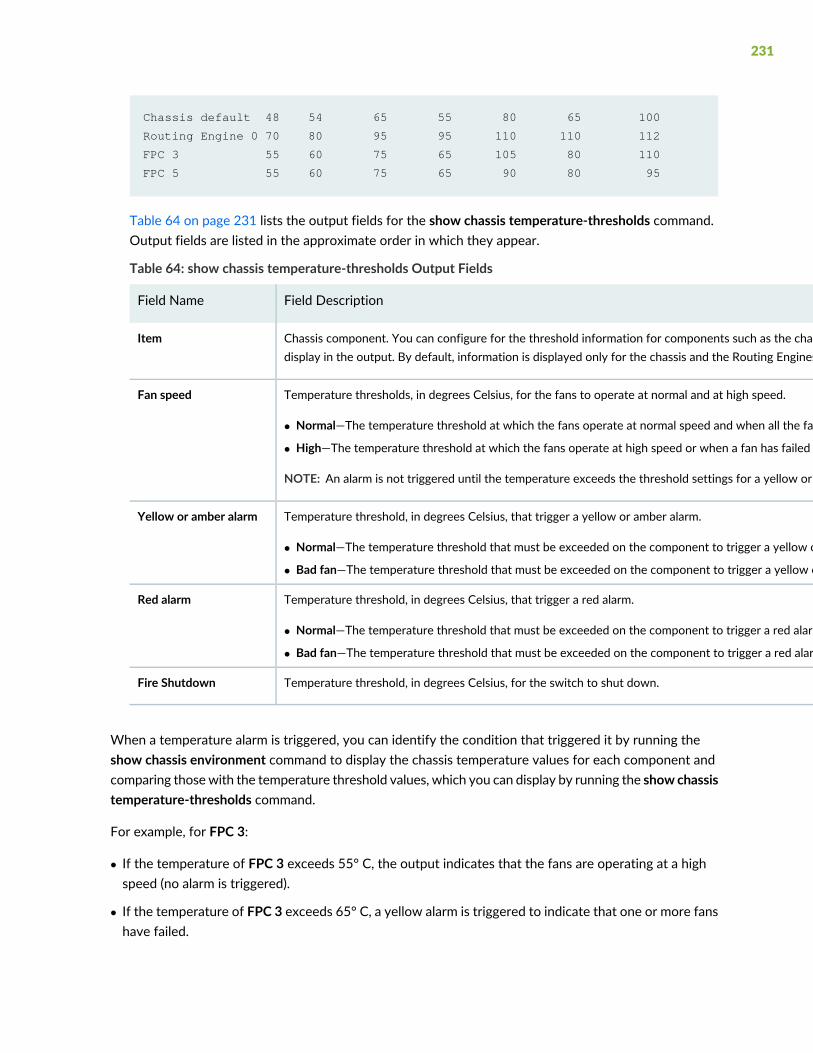
Chassis default 48 54 65 55 80 65 100
Routing Engine 0 70 80 95 95 110 110 112
FPC 3 55 60 75 65 105 80 110
FPC 5 55 60 75 65 90 80 95
Table 64 on page 231 lists the output fields for the show chassis temperature-thresholds command.Output fields are listed in the approximate order in which they appear.
Table 64: show chassis temperature-thresholds Output Fields
Field DescriptionField Name
Chassis component. You can configure for the threshold information for components such as the chassis, the Routing Engines, and FPC for each slot in each FRU todisplay in the output. By default, information is displayed only for the chassis and the Routing Engines.
Item
Temperature thresholds, in degrees Celsius, for the fans to operate at normal and at high speed.
• Normal—The temperature threshold at which the fans operate at normal speed and when all the fans are present and functioning normally.
• High—The temperature threshold at which the fans operate at high speed or when a fan has failed or is missing.
NOTE: An alarm is not triggered until the temperature exceeds the threshold settings for a yellow or amber alarm or a red alarm.
Fan speed
Temperature threshold, in degrees Celsius, that trigger a yellow or amber alarm.
• Normal—The temperature threshold that must be exceeded on the component to trigger a yellow or amber alarm when the fans are running at full speed.
• Bad fan—The temperature threshold that must be exceeded on the component to trigger a yellow or amber alarm when one or more fans have failed or are missing.
Yellow or amber alarm
Temperature threshold, in degrees Celsius, that trigger a red alarm.
• Normal—The temperature threshold that must be exceeded on the component to trigger a red alarm when the fans are running at full speed.
• Bad fan—The temperature threshold that must be exceeded on the component to trigger a red alarm when one or more fans have failed or are missing.
Red alarm
Temperature threshold, in degrees Celsius, for the switch to shut down.Fire Shutdown
When a temperature alarm is triggered, you can identify the condition that triggered it by running theshow chassis environment command to display the chassis temperature values for each component andcomparing thosewith the temperature threshold values, which you can display by running the show chassistemperature-thresholds command.
For example, for FPC 3:
• If the temperature of FPC 3 exceeds 55° C, the output indicates that the fans are operating at a highspeed (no alarm is triggered).
• If the temperature of FPC 3 exceeds 65° C, a yellow alarm is triggered to indicate that one or more fanshave failed.
231

• If the temperature of FPC 3 exceeds 75° C, a yellow alarm is triggered to indicate that the temperaturethreshold limit is exceeded.
• If the temperature of FPC 3 exceeds 80° C, a red alarm is triggered to indicate that one or more fanshave failed.
• If the temperature of FPC 3 exceeds 105° C, a red alarm is triggered to indicate that the temperaturethreshold limit is exceeded.
• If the temperature of FPC 3 exceeds 110° C, the switch is powered off.
Table 65 on page 232 lists the possible causes for the switch to generate a temperature alarm and therespective remedies.
Table 65: Causes and Remedies for Temperature Alarms
RemedyCause
Ensure that the ambient temperature is within the threshold temperature limit. See“Environmental Requirements and Specifications for EX Series Switches” on page 54.
Ambient temperature is abovethreshold temperature.
• Check the fan.
• Replace the faulty fan module or fan tray.
• If the above two checks show no problems, open a support case using the CaseManager link at https://www.juniper.net/support/ or call 1-888-314-5822(toll-free within the United States and Canada) or 1-408-745-9500 (from outsidethe United States).
Fan module or fan tray hasfailed.
Ensure that there is sufficient clearance around the installed switch. See the followingtopics to understand the clearance requirements of various EX Series switches.
Restricted airflow through theswitch due to insufficientclearance around the installedswitch.
232

6CHAPTER
Contacting Customer Support andReturning the Chassis or Components
Returning an EX3400 Chassis or Components | 234
Returning an EX3400 Chassis or Components
IN THIS SECTION
Returning an EX3400 Switch or Component for Repair or Replacement | 234
Locating the Serial Number on an EX3400 Switch or Component | 235
Contact Customer Support to Obtain Return Material Authorization | 237
Packing an EX3400 Switch or Component for Shipping | 237
Returning an EX3400 Switch or Component for Repair or Replacement
If you need to return an EX3400 switch or hardware component to Juniper Networks for repair orreplacement, follow this procedure:
1. Determine the serial number of the component. For instructions, see “Locating the Serial Number onan EX3400 Switch or Component” on page 235.
2. Obtain an RMA number from JTAC as described in “Contact Customer Support to Obtain ReturnMaterial Authorization” on page 237.
NOTE: Do not return any component to Juniper Networks unless you have first obtained anRMA number. Juniper Networks reserves the right to refuse shipments that do not have anRMA. Refused shipments are returned to the customer through collect freight.
3. Pack the switch or component for shipping as described in “Packing an EX3400 Switch or Componentfor Shipping” on page 237.
For more information about return and repair policies, see the customer support page athttps://www.juniper.net/support/guidelines.html.
234
Locating the Serial Number on an EX3400 Switch or Component
IN THIS SECTION
Listing the Switch and Components Details with the CLI | 235
Locating the Chassis Serial Number ID Label on an EX3400 Switch | 236
If you are returning an EX3400 switch or hardware component to Juniper Networks for repair orreplacement, you must locate the serial number of the switch or component. You must provide the serialnumber to the Juniper Networks Technical Assistance Center (JTAC) when you contact them to obtainReturn Material Authorization (RMA).
If the switch is operational and you can access the CLI, you can list serial numbers for the switch and forsome components with a CLI command. If you do not have access to the CLI or if the serial number forthe component does not appear in the command output, you can locate the serial number ID label on thephysical switch (see Figure 61 on page 236 and Figure 62 on page 236) or component.
NOTE: If you want to find the serial number on the physical switch component, you will needto remove the component from the switch chassis, for which you must have the required partsand tools available.
Listing the Switch and Components Details with the CLI
To list the switch and switch components and their serial numbers, enter the following CLI command:
user@switch> show chassis hardware
Hardware inventory:
Item Version Part number Serial number Description
Chassis NY0215350046
Routing Engine 1 BUILTIN BUILTIN RE-EX3400-48P
FPC 0 REV 05 650-059857 NY0215350046 EX3400-48P
CPU BUILTIN BUILTIN FPC CPU
PIC 0 REV 05 BUILTIN BUILTIN 48x10/100/1000 Base-T
PIC 1 REV 05 650-059857 NY0215350046 2x40G QSFP
Xcvr 0 REV 740-044512 APF14500007NFC QSFP+-40G-CU50CM
235
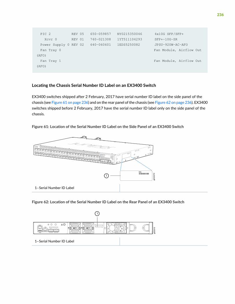
PIC 2 REV 05 650-059857 NY0215350046 4x10G SFP/SFP+
Xcvr 0 REV 01 740-021308 1YT511104293 SFP+-10G-SR
Power Supply 0 REV 02 640-060601 1EDS5250082 JPSU-920W-AC-AFO
Fan Tray 0 Fan Module, Airflow Out
(AFO)
Fan Tray 1 Fan Module, Airflow Out
(AFO)
Locating the Chassis Serial Number ID Label on an EX3400 Switch
EX3400 switches shipped after 2 February, 2017 have serial number ID label on the side panel of thechassis (see Figure 61 on page 236) and on the rear panel of the chassis (see Figure 62 on page 236). EX3400switches shipped before 2 February, 2017 have the serial number ID label only on the side panel of thechassis.
Figure 61: Location of the Serial Number ID Label on the Side Panel of an EX3400 Switch
1—Serial Number ID Label
Figure 62: Location of the Serial Number ID Label on the Rear Panel of an EX3400 Switch
g022
315
1
1—Serial Number ID Label
236
Contact Customer Support to Obtain Return Material Authorization
If you are returning a device or hardware component to Juniper Networks for repair or replacement, obtaina ReturnMaterial Authorization (RMA) number from Juniper Networks Technical Assistance Center (JTAC).
After locating the serial number of the device or hardware component you want to return, open a servicerequest with Juniper Networks Technical Assistance Center (JTAC) on the Web or by telephone.
Before you request an RMA number from JTAC, be prepared to provide the following information:
• Your existing service request number, if you have one
• Serial number of the component
• Your name, organization name, telephone number, fax number, and shipping address
• Details of the failure or problem
• Type of activity being performed on the device when the problem occurred
• Configuration data displayed by one or more show commands
You can contact JTAC 24 hours a day, seven days a week on the Web or by telephone:
• Service Request Manager: https://support.juniper.net/support
• Telephone: +1-888-314-JTAC (+1-888-314-5822), toll free in U.S., Canada, and Mexico
NOTE: For international or direct-dial options in countries without toll free numbers, seehttps://support.juniper.net/support
If you are contacting JTAC by telephone, enter your 12-digit service request number followed by thepound (#) key for an existing case, or press the star (*) key to be routed to the next available supportengineer.
The support representative validates your request and issues an RMAnumber for return of the component.
Packing an EX3400 Switch or Component for Shipping
IN THIS SECTION
Packing a Switch for Shipping | 238
Packing Switch Components for Shipping | 239
237

If you are returning an EX3400 switch or component to Juniper Networks for repair or replacement, packthe item as described in this topic.
Before you begin, ensure that you have retrieved the original shipping carton and packingmaterials. Contactyour JTAC representative if you do not have these materials, to learn about approved packing materials.See “Contact Customer Support to Obtain Return Material Authorization” on page 237.
Ensure that you have the following parts and tools available:
• Antistatic bag, one for each switch or component
• Phillips (+) screwdriver, number 2
Packing a Switch for Shipping
To pack a switch for shipping:
1. On the console or other management device connected to the switch, enter the CLI operational modeand issue the following command to shut down the switch software:
user@switch> request system halt
Wait until a message appears on the console confirming that the operating system has halted.
2. Disconnect power from the switch by performing one of the following:
• If the power source outlet has a power switch, set it to the OFF (0) position.
• If the power source outlet does not have a power switch, gently pull out the plug end of the powercord connected to the power source outlet.
3. Remove the cables that connect the switch to all external devices. See “Disconnect a Fiber-Optic Cable”on page 211.
4. Remove all optical transceivers installed in the switch. See “Remove a Transceiver” on page 207.
5. If the switch is mounted on a wall or on two posts, have one person support the weight of the switchwhile another person unscrews and removes the mounting screws. Use the Phillips (+) screwdriver toremove the screws.
6. Remove the switch from the wall, rack, cabinet, or desk and place the switch in an antistatic bag.
7. Slip on the end caps of the packaging foam on both sides of the switch.
8. Place the switch in the shipping carton.
238

9. Place the packing foam on top of and around the switch.
10. If you are returning accessories or FRUs with the switch, pack them as instructed in “Packing SwitchComponents for Shipping” on page 239.
11.Close the top of the cardboard carton and seal it with packing tape.
12.Write the RMA number on the exterior of the carton to ensure proper tracking.
Packing Switch Components for Shipping
To pack and ship switch components:
• Place individual components in antistatic bags.
• Ensure that the components are adequately protected with packing materials and packed so that thepieces are prevented from moving around inside the carton.
• Close the top of the cardboard shipping carton and seal it with packing tape.
• Write the RMA number on the exterior of the carton to ensure proper tracking.
239

7CHAPTER
Safety and Compliance Information
General Safety Guidelines and Warnings | 242
Definitions of Safety Warning Levels | 243
Qualified Personnel Warning | 246
Warning Statement for Norway and Sweden | 247
Fire Safety Requirements | 247
Installation Instructions Warning | 249
Chassis and Component Lifting Guidelines | 249
Restricted Access Warning | 251
Ramp Warning | 253
Rack-Mounting and Cabinet-Mounting Warnings | 254
Grounded Equipment Warning | 260
Laser and LED Safety Guidelines and Warnings | 261
Radiation from Open Port Apertures Warning | 265
Maintenance and Operational Safety Guidelines and Warnings | 266
General Electrical Safety Guidelines and Warnings | 274

Action to Take After an Electrical Accident | 275
Prevention of Electrostatic Discharge Damage | 276
AC Power Electrical Safety Guidelines | 277
AC Power Disconnection Warning | 279
DC Power Electrical Safety Guidelines | 280
DC Power Disconnection Warning | 281
DC Power Grounding Requirements and Warning | 283
DC Power Wiring Sequence Warning | 285
DC Power Wiring Terminations Warning | 288
Multiple Power Supplies Disconnection Warning | 291
TN Power Warning | 292
Agency Approvals for EX Series Switches | 292
Compliance Statements for EMC Requirements for EX Series Switches | 293
Compliance Statements for Acoustic Noise for EX Series Switches | 298

General Safety Guidelines and Warnings
The following guidelines help ensure your safety and protect the device from damage. The list of guidelinesmight not address all potentially hazardous situations in your working environment, so be alert and exercisegood judgment at all times.
• Perform only the procedures explicitly described in the hardware documentation for this device. Makesure that only authorized service personnel perform other system services.
• Keep the area around the device clear and free from dust before, during, and after installation.
• Keep tools away from areas where people could trip over them while walking.
• Do not wear loose clothing or jewelry, such as rings, bracelets, or chains, which could become caughtin the device.
• Wear safety glasses if you are working under any conditions that could be hazardous to your eyes.
• Do not perform any actions that create a potential hazard to people or make the equipment unsafe.
• Never attempt to lift an object that is too heavy for one person to handle.
• Never install or manipulate wiring during electrical storms.
• Never install electrical jacks in wet locations unless the jacks are specifically designed for wetenvironments.
• Operate the device only when it is properly grounded.
• Follow the instructions in this guide to properly ground the device to earth.
• Replace fuses only with fuses of the same type and rating.
• Do not open or remove chassis covers or sheet-metal parts unless instructions are provided in thehardware documentation for this device. Such an action could cause severe electrical shock.
• Do not push or force any objects through any opening in the chassis frame. Such an action could resultin electrical shock or fire.
• Avoid spilling liquid onto the chassis or onto any device component. Such an action could cause electricalshock or damage the device.
• Avoid touching uninsulated electrical wires or terminals that have not been disconnected from theirpower source. Such an action could cause electrical shock.
• Some parts of the chassis, including AC and DC power supply surfaces, power supply unit handles, SFBcard handles, and fan tray handles might become hot. The following label provides the warning of thehot surfaces on the chassis:
242
• Always ensure that all modules, power supplies, and cover panels are fully inserted and that the installationscrews are fully tightened.
Definitions of Safety Warning Levels
The documentation uses the following levels of safety warnings (there are twoWarning formats):
NOTE: You might find this information helpful in a particular situation, or you might overlookthis important information if it was not highlighted in a Note.
CAUTION: You need to observe the specified guidelines to prevent minor injury ordiscomfort to you or severe damage to the device.
Attention Veillez à respecter les consignes indiquées pour éviter toute incommoditéou blessure légère, voire des dégâts graves pour l’appareil.
WARNING: This symbol alerts you to the risk of personal injury from a laser.
Avertissement Ce symbole signale un risque de blessure provoquée par rayon laser.
243

244

WARNING: This symbol means danger. You are in a situation that could cause bodilyinjury. Before you work on any equipment, be aware of the hazards involved withelectrical circuitry and be familiar with standard practices for preventing accidents.
WaarschuwingDit waarschuwingssymbool betekent gevaar. U verkeert in een situatiedie lichamelijk letsel kan veroorzaken. Voordat u aan enige apparatuur gaat werken,dient u zich bewust te zijn van de bij elektrische schakelingen betrokken risico's endient u op de hoogte te zijn van standaard maatregelen om ongelukken te voorkomen.
Varoitus Tämä varoitusmerkki merkitsee vaaraa. Olet tilanteessa, joka voi johtaaruumiinvammaan. Ennen kuin työskentelet minkään laitteiston parissa, ota selvääsähkökytkentöihin liittyvistä vaaroista ja tavanomaisista onnettomuuksienehkäisykeinoista.
Avertissement Ce symbole d'avertissement indique un danger. Vous vous trouvezdans une situation pouvant causer des blessures ou des dommages corporels. Avantde travailler sur un équipement, soyez conscient des dangers posés par les circuitsélectriques et familiarisez-vous avec les procédures couramment utilisées pour éviterles accidents.
Warnung Dieses Warnsymbol bedeutet Gefahr. Sie befinden sich in einer Situation,die zu einer Körperverletzung führen könnte. Bevor Sie mit der Arbeit an irgendeinemGerät beginnen, seien Sie sich dermit elektrischen Stromkreisen verbundenenGefahrenund der Standardpraktiken zur Vermeidung von Unfällen bewußt.
Avvertenza Questo simbolo di avvertenza indica un pericolo. La situazione potrebbecausare infortuni alle persone. Prima di lavorare su qualsiasi apparecchiatura, occorreconoscere i pericoli relativi ai circuiti elettrici ed essere al corrente delle pratichestandard per la prevenzione di incidenti.
AdvarselDette varselsymbolet betyr fare. Du befinner deg i en situasjon som kan føretil personskade. Før du utfører arbeid på utstyr, må du vare oppmerksom på defaremomentene som elektriske kretser innebærer, samt gjøre deg kjent med vanligpraksis når det gjelder å unngå ulykker.
Aviso Este símbolo de aviso indica perigo. Encontra-se numa situação que lhe poderácausar danos físicos. Antes de começar a trabalhar com qualquer equipamento,familiarize-se com os perigos relacionados com circuitos eléctricos, e com quaisquerpráticas comuns que possam prevenir possíveis acidentes.
¡Atención! Este símbolo de aviso significa peligro. Existe riesgo para su integridad física.Antes de manipular cualquier equipo, considerar los riesgos que entraña la corrienteeléctrica y familiarizarse con los procedimientos estándar de prevención de accidentes.
245
Varning!Denna varningssymbol signalerar fara. Du befinner dig i en situation som kanleda till personskada. Innan du utför arbete på någon utrustningmåste du varamedvetenom farorna med elkretsar och känna till vanligt förfarande för att förebygga skador.
Qualified Personnel Warning
WARNING: Only trained and qualified personnel should install or replace the device.
Waarschuwing Installatie en reparaties mogen uitsluitend door getraind en bevoegdpersoneel uitgevoerd worden.
Varoitus Ainoastaan koulutettu ja pätevä henkilökunta saa asentaa tai vaihtaa tämänlaitteen.
Avertissement Tout installation ou remplacement de l'appareil doit être réalisé par dupersonnel qualifié et compétent.
Warnung Gerät nur von geschultem, qualifiziertem Personal installieren oderauswechseln lassen.
Avvertenza Solo personale addestrato e qualificato deve essere autorizzato ad installareo sostituire questo apparecchio.
AdvarselKun kvalifisert personell med riktig opplæring børmontere eller bytte ut detteutstyret.
Aviso Este equipamento deverá ser instalado ou substituído apenas por pessoaldevidamente treinado e qualificado.
¡Atención! Estos equipos deben ser instalados y reemplazados exclusivamente porpersonal técnico adecuadamente preparado y capacitado.
Varning! Denna utrustning ska endast installeras och bytas ut av utbildad ochkvalificerad personal.
246

Warning Statement for Norway and Sweden
WARNING: The equipment must be connected to an earthed mains socket-outlet.
Advarsel Apparatet skal kobles til en jordet stikkontakt.
Varning! Apparaten skall anslutas till jordat nätuttag.
Fire Safety Requirements
In the event of a fire emergency, the safety of people is the primary concern. You should establishprocedures for protecting people in the event of a fire emergency, provide safety training, and properlyprovision fire-control equipment and fire extinguishers.
In addition, you should establish procedures to protect your equipment in the event of a fire emergency.Juniper Networks products should be installed in an environment suitable for electronic equipment. Werecommend that fire suppression equipment be available in the event of a fire in the vicinity of theequipment and that all local fire, safety, and electrical codes and ordinances be observed when you installand operate your equipment.
Fire Suppression
In the event of an electrical hazard or an electrical fire, you should first turn power off to the equipmentat the source. Then use a Type C fire extinguisher, which uses noncorrosive fire retardants, to extinguishthe fire.
Fire Suppression Equipment
Type C fire extinguishers, which use noncorrosive fire retardants such as carbon dioxide and Halotron™,are most effective for suppressing electrical fires. Type C fire extinguishers displace oxygen from the pointof combustion to eliminate the fire. For extinguishing fire on or around equipment that draws air from theenvironment for cooling, you should use this type of inert oxygen displacement extinguisher instead of anextinguisher that leaves residues on equipment.
247

Do not use multipurpose Type ABC chemical fire extinguishers (dry chemical fire extinguishers). Theprimary ingredient in these fire extinguishers is monoammonium phosphate, which is very sticky anddifficult to clean. In addition, in the presence of minute amounts of moisture, monoammonium phosphatecan become highly corrosive and corrodes most metals.
Any equipment in a room inwhich a chemical fire extinguisher has been discharged is subject to prematurefailure and unreliable operation. The equipment is considered to be irreparably damaged.
NOTE: To keep warranties effective, do not use a dry chemical fire extinguisher to control a fireat or near a Juniper Networks device. If a dry chemical fire extinguisher is used, the unit is nolonger eligible for coverage under a service agreement.
We recommend that you dispose of any irreparably damaged equipment in an environmentally responsiblemanner.
248
Installation Instructions Warning
WARNING: Read the installation instructions before you connect the device to apower source.
Waarschuwing Raadpleeg de installatie-aanwijzingen voordat u het systeem met devoeding verbindt.
Varoitus Lue asennusohjeet ennen järjestelmän yhdistämistä virtalähteeseen.
Avertissement Avant de brancher le système sur la source d'alimentation, consulterles directives d'installation.
Warnung Lesen Sie die Installationsanweisungen, bevor Sie das System an dieStromquelle anschließen.
Avvertenza Consultare le istruzioni di installazione prima di collegare il sistemaall'alimentatore.
Advarsel Les installasjonsinstruksjonene før systemet kobles til strømkilden.
Aviso Leia as instruções de instalação antes de ligar o sistema à sua fonte de energia.
¡Atención! Ver las instrucciones de instalación antes de conectar el sistema a la red dealimentación.
Varning! Läs installationsanvisningarna innan du kopplar systemet till dessströmförsörjningsenhet.
Chassis and Component Lifting Guidelines
• Before moving the device to a site, ensure that the site meets the power, environmental, and clearancerequirements.
• Before lifting or moving the device, disconnect all external cables and wires.
• As when lifting any heavy object, ensure that most of the weight is borne by your legs rather than yourback. Keep your knees bent and your back relatively straight. Do not twist your body as you lift. Balancethe load evenly and be sure that your footing is firm.
• Use the following lifting guidelines to lift devices and components:
249

• Up to 39.7 lbs (18 kg): One person.
• 39.7 lbs (18 kg) to 70.5 lbs (32 kg): Two or more people.
• 70.5 lbs (32 kg) to 121.2 lbs (55 kg): Three or more people.
• Above 121.2 lbs (55 kg): Material handling systems (such as levers, slings, lifts and so on) must be used.When this is not practical, specially trained persons or systems must be used (riggers or movers).
250

Restricted Access Warning
251

WARNING: This unit is intended for installation in restricted access areas. A restrictedaccess area is an area to which access can be gained only by service personnel throughthe use of a special tool, lock and key, or other means of security, and which iscontrolled by the authority responsible for the location.
WaarschuwingDit toestel is bedoeld voor installatie op plaatsenmet beperkte toegang.Een plaats met beperkte toegang is een plaats waar toegang slechts doorservicepersoneel verkregen kan worden door middel van een speciaal instrument, eenslot en sleutel, of een ander veiligheidsmiddel, en welke beheerd wordt door deoverheidsinstantie die verantwoordelijk is voor de locatie.
Varoitus Tämä laite on tarkoitettu asennettavaksi paikkaan, johon pääsy on rajoitettua.Paikka, johon pääsy on rajoitettua, tarkoittaa paikkaa, johon vain huoltohenkilöstöpääsee jonkin erikoistyökalun, lukkoon sopivan avaimen tai jonkin muun turvalaitteenavulla ja joka on paikasta vastuussa olevien toimivaltaisten henkilöiden valvoma.
AvertissementCet appareil est à installer dans des zones d'accès réservé. Ces dernièressont des zones auxquelles seul le personnel de service peut accéder en utilisant unoutil spécial, unmécanisme de verrouillage et une clé, ou tout autremoyen de sécurité.L'accès aux zones de sécurité est sous le contrôle de l'autorité responsable del'emplacement.
Warnung Diese Einheit ist zur Installation in Bereichen mit beschränktem Zutrittvorgesehen. Ein Bereich mit beschränktem Zutritt ist ein Bereich, zu dem nurWartungspersonal mit einem Spezialwerkzeugs, Schloß und Schlüssel oder andererSicherheitsvorkehrungen Zugang hat, und der von dem für die Anlage zuständigenGremium kontrolliert wird.
AvvertenzaQuesta unità deve essere installata in un'area ad accesso limitato. Un'areaad accesso limitato è un'area accessibile solo a personale di assistenza tramiteun'attrezzo speciale, lucchetto, o altri dispositivi di sicurezza, ed è controllatadall'autorità responsabile della zona.
Advarsel Denne enheten er laget for installasjon i områder med begrenset adgang. Etområde med begrenset adgang gir kun adgang til servicepersonale som bruker etspesielt verktøy, lås og nøkkel, eller en annen sikkerhetsanordning, og det kontrolleresav den autoriteten som er ansvarlig for området.
Aviso Esta unidade foi concebida para instalação em áreas de acesso restrito. Umaárea de acesso restrito é uma área à qual apenas tem acesso o pessoal de serviçoautorizado, que possua uma ferramenta, chave e fechadura especial, ou qualquer outraforma de segurança. Esta área é controlada pela autoridade responsável pelo local.
252
¡Atención! Esta unidad ha sido diseñada para instalarse en áreas de acceso restringido.Área de acceso restringido significa un área a la que solamente tiene acceso el personalde servicio mediante la utilización de una herramienta especial, cerradura con llave, oalgún otro medio de seguridad, y que está bajo el control de la autoridad responsabledel local.
Varning!Denna enhet är avsedd för installation i områden med begränsat tillträde. Ettområdemed begränsat tillträde får endast tillträdas av servicepersonal med ett specielltverktyg, lås och nyckel, eller annan säkerhetsanordning, och kontrolleras av denauktoritet som ansvarar för området.
RampWarning
WARNING: When installing the device, do not use a ramp inclined at more than 10degrees.
Waarschuwing Gebruik een oprijplaat niet onder een hoek van meer dan 10 graden.
Varoitus Älä käytä sellaista kaltevaa pintaa, jonka kaltevuus ylittää 10 astetta.
AvertissementNe pas utiliser une rampe dont l'inclinaison est supérieure à 10 degrés.
Warnung Keine Rampen mit einer Neigung von mehr als 10 Grad verwenden.
Avvertenza Non usare una rampa con pendenza superiore a 10 gradi.
Advarsel Bruk aldri en rampe som heller mer enn 10 grader.
Aviso Não utilize uma rampa com uma inclinação superior a 10 graus.
¡Atención! No usar una rampa inclinada más de 10 grados
Varning! Använd inte ramp med en lutning på mer än 10 grader.
253

Rack-Mounting and Cabinet-Mounting Warnings
Ensure that the rack or cabinet in which the device is installed is evenly and securely supported. Unevenmechanical loading could lead to a hazardous condition.
254

255

WARNING: To prevent bodily injury when mounting or servicing the device in a rack,take the following precautions to ensure that the system remains stable. The followingdirectives help maintain your safety:
• The device must be installed in a rack that is secured to the building structure.
• The device should be mounted at the bottom of the rack if it is the only unit in therack.
• When mounting the device on a partially filled rack, load the rack from the bottomto the top with the heaviest component at the bottom of the rack.
• If the rack is provided with stabilizing equipment, install the stabilizers beforemounting or servicing the device in the rack.
Waarschuwing Om lichamelijk letsel te voorkomen wanneer u dit toestel in een rekmonteert of het daar een servicebeurt geeft, moet u speciale voorzorgsmaatregelennemen om ervoor te zorgen dat het toestel stabiel blijft. De onderstaande richtlijnenworden verstrekt om uw veiligheid te verzekeren:
• De Juniper Networks switch moet in een stellage worden geïnstalleerd die aan eenbouwsel is verankerd.
• Dit toestel dient onderaan in het rek gemonteerd te worden als het toestel het enigein het rek is.
• Wanneer u dit toestel in een gedeeltelijk gevuld rek monteert, dient u het rek vanonderen naar boven te laden met het zwaarste onderdeel onderaan in het rek.
• Als het rek voorzien is van stabiliseringshulpmiddelen, dient u de stabilisatoren temonteren voordat u het toestel in het rek monteert of het daar een servicebeurtgeeft.
Varoitus Kun laite asetetaan telineeseen tai huolletaan sen ollessa telineessä, onnoudatettava erityisiä varotoimia järjestelmän vakavuuden säilyttämiseksi, jottavältytään loukkaantumiselta. Noudata seuraavia turvallisuusohjeita:
• Juniper Networks switch on asennettava telineeseen, joka on kiinnitettyrakennukseen.
• Jos telineessä ei ole muita laitteita, aseta laite telineen alaosaan.
• Jos laite asetetaan osaksi täytettyyn telineeseen, aloita kuormittaminen sen alaosastakaikkein raskaimmalla esineellä ja siirry sitten sen yläosaan.
• Jos telinettä varten on vakaimet, asenna ne ennen laitteen asettamista telineeseentai sen huoltamista siinä.
256

AvertissementPour éviter toute blessure corporelle pendant les opérations demontageou de réparation de cette unité en casier, il convient de prendre des précautionsspéciales afin de maintenir la stabilité du système. Les directives ci-dessous sontdestinées à assurer la protection du personnel:
• Le rack sur lequel est monté le Juniper Networks switch doit être fixé à la structuredu bâtiment.
• Si cette unité constitue la seule unité montée en casier, elle doit être placée dans lebas.
• Si cette unité est montée dans un casier partiellement rempli, charger le casier debas en haut en plaçant l'élément le plus lourd dans le bas.
• Si le casier est équipé de dispositifs stabilisateurs, installer les stabilisateurs avantde monter ou de réparer l'unité en casier.
Warnung Zur Vermeidung von Körperverletzung beim Anbringen oder Warten dieserEinheit in einem Gestell müssen Sie besondere Vorkehrungen treffen, umsicherzustellen, daß das System stabil bleibt. Die folgenden Richtlinien sollen zurGewährleistung Ihrer Sicherheit dienen:
• Der Juniper Networks switch muß in einem Gestell installiert werden, das in derGebäudestruktur verankert ist.
• Wenn diese Einheit die einzige im Gestell ist, sollte sie unten im Gestell angebrachtwerden.
• Bei Anbringung dieser Einheit in einem zum Teil gefüllten Gestell ist das Gestell vonunten nach oben zu laden, wobei das schwerste Bauteil unten imGestell anzubringenist.
• Wird das Gestell mit Stabilisierungszubehör geliefert, sind zuerst die Stabilisatorenzu installieren, bevor Sie die Einheit im Gestell anbringen oder sie warten.
Avvertenza Per evitare infortuni fisici durante il montaggio o la manutenzione di questaunità in un supporto, occorre osservare speciali precauzioni per garantire che il sistemarimanga stabile. Le seguenti direttive vengono fornite per garantire la sicurezzapersonale:
257

• Il Juniper Networks switch deve essere installato in un telaio, il quale deve esserefissato alla struttura dell'edificio.
• Questa unità deve venire montata sul fondo del supporto, se si tratta dell'unica unitàda montare nel supporto.
• Quando questa unità viene montata in un supporto parzialmente pieno, caricare ilsupporto dal basso all'alto, con il componente più pesante sistemato sul fondo delsupporto.
• Se il supporto è dotato di dispositivi stabilizzanti, installare tali dispositivi prima dimontare o di procedere alla manutenzione dell'unità nel supporto.
Advarsel Unngå fysiske skader under montering eller reparasjonsarbeid på denneenheten når den befinner seg i et kabinett. Vær nøye med at systemet er stabilt.Følgende retningslinjer er gitt for å verne om sikkerheten:
• Juniper Networks switch må installeres i et stativ som er forankret tilbygningsstrukturen.
• Denne enheten bør monteres nederst i kabinettet hvis dette er den eneste enheteni kabinettet.
• Ved montering av denne enheten i et kabinett som er delvis fylt, skal kabinettetlastes fra bunnen og opp med den tyngste komponenten nederst i kabinettet.
• Hvis kabinettet er utstyrt med stabiliseringsutstyr, skal stabilisatorene installeres førmontering eller utføring av reparasjonsarbeid på enheten i kabinettet.
Aviso Para se prevenir contra danos corporais aomontar ou reparar esta unidade numaestante, deverá tomar precauções especiais para se certificar de que o sistema possuium suporte estável. As seguintes directrizes ajudá-lo-ão a efectuar o seu trabalho comsegurança:
• O Juniper Networks switch deverá ser instalado numa prateleira fixa à estrutura doedificio.
• Esta unidade deverá ser montada na parte inferior da estante, caso seja esta a únicaunidade a ser montada.
• Ao montar esta unidade numa estante parcialmente ocupada, coloque os itens maispesados na parte inferior da estante, arrumando-os de baixo para cima.
• Se a estante possuir um dispositivo de estabilização, instale-o antes de montar oureparar a unidade.
¡Atención! Para evitar lesiones durante el montaje de este equipo sobre un bastidor,oeriormente durante sumantenimiento, se debe ponermucho cuidado en que el sistemaquede bien estable. Para garantizar su seguridad, proceda según las siguientesinstrucciones:
258

• El Juniper Networks switch debe instalarse en un bastidor fijado a la estructura deledificio.
• Colocar el equipo en la parte inferior del bastidor, cuando sea la única unidad en elmismo.
• Cuando este equipo se vaya a instalar en un bastidor parcialmente ocupado, comenzarla instalación desde la parte inferior hacia la superior colocando el equipomás pesadoen la parte inferior.
• Si el bastidor dispone de dispositivos estabilizadores, instalar éstos antes de montaro proceder al mantenimiento del equipo instalado en el bastidor.
Varning! För att undvika kroppsskada när du installerar eller utför underhållsarbete pådenna enhet på en ställning måste du vidta särskilda försiktighetsåtgärder för attförsäkra dig om att systemet står stadigt. Följande riktlinjer ges för att trygga dinsäkerhet:
• JuniperNetworks switchmåste installeras i en ställning som är förankrad i byggnadensstruktur.
• Om denna enhet är den enda enheten på ställningen skall den installeras längst nedpå ställningen.
• Omdenna enhet installeras på en delvis fylld ställning skall ställningen fyllas nedifrånoch upp, med de tyngsta enheterna längst ned på ställningen.
• Om ställningen är försedd med stabiliseringsdon skall dessa monteras fast innanenheten installeras eller underhålls på ställningen.
259

Grounded Equipment Warning
WARNING: This devicemust be properly grounded at all times. Follow the instructionsin this guide to properly ground the device to earth.
Waarschuwing Dit apparaat moet altijd goed geaard zijn. Volg de instructies in dezegids om het apparaat goed te aarden.
Varoitus Laitteen on oltava pysyvästi maadoitettu. Maadoita laite asianmukaisestinoudattamalla tämän oppaan ohjeita.
Avertissement L’appareil doit être correctement mis à la terre à tout moment. Suivezles instructions de ce guide pour correctement mettre l’appareil à la terre.
Warnung Das Gerät muss immer ordnungsgemäß geerdet sein. Befolgen Sie dieAnweisungen in dieser Anleitung, um das Gerät ordnungsgemäß zu erden.
Avvertenza Questo dispositivo deve sempre disporre di una connessione a massa.Seguire le istruzioni indicate in questa guida per connettere correttamente il dispositivoa massa.
Advarsel Denne enheten på jordes skikkelig hele tiden. Følg instruksjonene i denneveiledningen for å jorde enheten.
Aviso Este equipamento deverá estar ligado à terra. Siga las instrucciones en esta guíapara conectar correctamente este dispositivo a tierra.
¡Atención! Este dispositivo debe estar correctamente conectado a tierra en todomomento. Siga las instrucciones en esta guía para conectar correctamente estedispositivo a tierra.
Varning! Den här enheten måste vara ordentligt jordad. Följ instruktionerna i den härguiden för att jorda enheten ordentligt.
260
Laser and LED Safety Guidelines and Warnings
IN THIS SECTION
General Laser Safety Guidelines | 261
Class 1 Laser Product Warning | 262
Class 1 LED Product Warning | 263
Laser BeamWarning | 264
Juniper Networks devices are equipped with laser transmitters, which are considered a Class 1 LaserProduct by the U.S. Food and Drug Administration and are evaluated as a Class 1 Laser Product per EN60825-1 requirements.
Observe the following guidelines and warnings:
General Laser Safety Guidelines
When working around ports that support optical transceivers, observe the following safety guidelines toprevent eye injury:
• Do not look into unterminated ports or at fibers that connect to unknown sources.
• Do not examine unterminated optical ports with optical instruments.
• Avoid direct exposure to the beam.
WARNING: Unterminated optical connectors can emit invisible laser radiation. Thelens in the human eye focuses all the laser power on the retina, so focusing the eyedirectly on a laser source—even a low-power laser—could permanently damage theeye.
Avertissement Les connecteurs à fibre optique sans terminaison peuvent émettreun rayonnement laser invisible. Le cristallin de l’œil humain faisant converger toutela puissance du laser sur la rétine, toute focalisation directe de l’œil sur une sourcelaser, —même de faible puissance—, peut entraîner des lésions oculaires irréversibles.
261

Class 1 Laser Product Warning
WARNING: Class 1 laser product.
Waarschuwing Klasse-1 laser produkt.
Varoitus Luokan 1 lasertuote.
Avertissement Produit laser de classe I.
Warnung Laserprodukt der Klasse 1.
Avvertenza Prodotto laser di Classe 1.
Advarsel Laserprodukt av klasse 1.
Aviso Produto laser de classe 1.
¡Atención! Producto láser Clase I.
Varning! Laserprodukt av klass 1.
262

Class 1 LED Product Warning
WARNING: Class 1 LED product.
Waarschuwing Klasse 1 LED-product.
Varoitus Luokan 1 valodiodituote.
Avertissement Alarme de produit LED Class I.
Warnung Class 1 LED-Produktwarnung.
Avvertenza Avvertenza prodotto LED di Classe 1.
Advarsel LED-produkt i klasse 1.
Aviso Produto de classe 1 com LED.
¡Atención! Aviso sobre producto LED de Clase 1.
Varning! Lysdiodprodukt av klass 1.
263
Laser BeamWarning
WARNING: Donot stare into the laser beamor view it directlywith optical instruments.
Waarschuwing Niet in de straal staren of hem rechtstreeks bekijken met optischeinstrumenten.
Varoitus Älä katso säteeseen äläkä tarkastele sitä suoraan optisen laitteen avulla.
Avertissement Ne pas fixer le faisceau des yeux, ni l'observer directement à l'aided'instruments optiques.
WarnungNicht direkt in den Strahl blicken und ihn nicht direkt mit optischen Gerätenprüfen.
Avvertenza Non fissare il raggio con gli occhi né usare strumenti ottici per osservarlodirettamente.
Advarsel Stirr eller se ikke direkte p strlen med optiske instrumenter.
AvisoNão olhe fixamente para o raio, nemolhe para ele directamente com instrumentosópticos.
¡Atención! No mirar fijamente el haz ni observarlo directamente con instrumentosópticos.
Varning! Rikta inte blicken in mot strålen och titta inte direkt på den genom optiskainstrument.
264

Radiation from Open Port Apertures Warning
WARNING: Because invisible radiation might be emitted from the aperture of theport when no fiber cable is connected, avoid exposure to radiation and do not stareinto open apertures.
Waarschuwing Aangezien onzichtbare straling vanuit de opening van de poort kankomen als er geen fiberkabel aangesloten is, dient blootstelling aan straling en hetkijken in open openingen vermeden te worden.
Varoitus Koska portin aukosta voi emittoitua näkymätöntä säteilyä, kun kuitukaapeliaei ole kytkettynä, vältä säteilylle altistumista äläkä katso avoimiin aukkoihin.
Avertissement Des radiations invisibles à l'il nu pouvant traverser l'ouverture du portlorsqu'aucun câble en fibre optique n'y est connecté, il est recommandé de ne pasregarder fixement l'intérieur de ces ouvertures.
Warnung Aus der Port-Öffnung können unsichtbare Strahlen emittieren, wenn keinGlasfaserkabel angeschlossen ist. Vermeiden Sie es, sich den Strahlungen auszusetzen,und starren Sie nicht in die Öffnungen!
AvvertenzaQuando i cavi in fibra non sono inseriti, radiazioni invisibili possono essereemesse attraverso l'apertura della porta. Evitate di esporvi alle radiazioni e non guardatedirettamente nelle aperture.
Advarsel Unngå utsettelse for stråling, og stirr ikke inn i åpninger som er åpne, fordiusynlig stråling kan emiteres fra portens åpning når det ikke er tilkoblet en fiberkabel.
Aviso Dada a possibilidade de emissão de radiação invisível através do orifício da viade acesso, quando esta não tiver nenhum cabo de fibra conectado, deverá evitar anEXposição à radiação e não deverá olhar fixamente para orifícios que se encontrarema descoberto.
¡Atención!Debido a que la apertura del puerto puede emitir radiación invisible cuandono existe un cable de fibra conectado, evite mirar directamente a las aperturas parano exponerse a la radiación.
Varning!Osynlig strålning kan avges från en portöppning utan ansluten fiberkabel ochdu bör därför undvika att bli utsatt för strålning genom att inte stirra in i oskyddadeöppningar.
265

Maintenance and Operational Safety Guidelines andWarnings
IN THIS SECTION
Battery Handling Warning | 267
Jewelry Removal Warning | 268
Lightning Activity Warning | 270
Operating Temperature Warning | 271
Product Disposal Warning | 273
While performing the maintenance activities for devices, observe the following guidelines and warnings:
266

Battery Handling Warning
WARNING: Replacing a battery incorrectly might result in an explosion. Replace abattery only with the same or equivalent type recommended by the manufacturer.Dispose of used batteries according to the manufacturer's instructions.
Waarschuwing Er is ontploffingsgevaar als de batterij verkeerd vervangen wordt.Vervang de batterij slechts met hetzelfde of een equivalent type dat door de fabrikantaanbevolen is. Gebruikte batterijen dienen overeenkomstig fabrieksvoorschriftenweggeworpen te worden.
VaroitusRäjähdyksen vaara, jos akku on vaihdettu väärään akkuun. Käytä vaihtamiseenainoastaan saman- tai vastaavantyyppistä akkua, joka on valmistajan suosittelema.Hävitä käytetyt akut valmistajan ohjeiden mukaan.
Avertissement Danger d'explosion si la pile n'est pas remplacée correctement. Ne laremplacer que par une pile de type semblable ou équivalent, recommandée par lefabricant. Jeter les piles usagées conformément aux instructions du fabricant.
Warnung Bei Einsetzen einer falschen Batterie besteht Explosionsgefahr. Ersetzen Siedie Batterie nur durch den gleichen oder vom Hersteller empfohlenen Batterietyp.Entsorgen Sie die benutzten Batterien nach den Anweisungen des Herstellers.
Advarsel Det kan være fare for eksplosjon hvis batteriet skiftes på feil måte. Skift kunmed samme eller tilsvarende type som er anbefalt av produsenten. Kasser bruktebatterier i henhold til produsentens instruksjoner.
AvvertenzaPericolo di esplosione se la batteria non è installata correttamente. Sostituiresolo con una di tipo uguale o equivalente, consigliata dal produttore. Eliminare lebatterie usate secondo le istruzioni del produttore.
Aviso Existe perigo de explosão se a bateria for substituída incorrectamente. Substituaa bateria por uma bateria igual ou de um tipo equivalente recomendado pelo fabricante.Destrua as baterias usadas conforme as instruções do fabricante.
¡Atención! Existe peligro de explosión si la batería se reemplaza de manera incorrecta.Reemplazar la baterían EXclusivamente con elmismo tipo o el equivalente recomendadopor el fabricante. Desechar las baterías gastadas según las instrucciones del fabricante.
Varning! Explosionsfara vid felaktigt batteribyte. Ersätt endast batteriet med sammabatterityp som rekommenderas av tillverkaren eller motsvarande. Följ tillverkarensanvisningar vid kassering av använda batterier.
267

Jewelry Removal Warning
268

WARNING: Before working on equipment that is connected to power lines, removejewelry, including rings, necklaces, andwatches.Metal objects heat upwhen connectedto power and ground and can cause serious burns or can be welded to the terminals.
Waarschuwing Alvorens aan apparatuur te werken die met elektrische leidingen isverbonden, sieraden (inclusief ringen, kettingen en horloges) verwijderen. Metalenvoorwerpenwordenwarmwanneer zemet stroom en aarde zijn verbonden, en kunnenernstige brandwonden veroorzaken of het metalen voorwerp aan de aansluitklemmenlassen.
Varoitus Ennen kuin työskentelet voimavirtajohtoihin kytkettyjen laitteiden parissa,ota pois kaikki korut (sormukset, kaulakorut ja kellot mukaan lukien). Metalliesineetkuumenevat, kun ne ovat yhteydessä sähkövirran ja maan kanssa, ja ne voivat aiheuttaavakavia palovammoja tai hitsata metalliesineet kiinni liitäntänapoihin.
AvertissementAvant d'accéder à cet équipement connecté aux lignes électriques, ôtertout bijou (anneaux, colliers et montres compris). Lorsqu'ils sont branchés àl'alimentation et reliés à la terre, les objets métalliques chauffent, ce qui peut provoquerdes blessures graves ou souder l'objet métallique aux bornes.
Warnung Vor der Arbeit an Geräten, die an das Netz angeschlossen sind, jeglichenSchmuck (einschließlich Ringe, Ketten und Uhren) abnehmen. Metallgegenständeerhitzen sich, wenn sie an das Netz und die Erde angeschlossen werden, und könnenschwere Verbrennungen verursachen oder an die Anschlußklemmen angeschweißtwerden.
Avvertenza Prima di intervenire su apparecchiature collegate alle linee di alimentazione,togliersi qualsiasi monile (inclusi anelli, collane, braccialetti ed orologi). Gli oggettimetallici si riscaldano quando sono collegati tra punti di alimentazione emassa: possonocausare ustioni gravi oppure il metallo può saldarsi ai terminali.
Advarsel Fjern alle smykker (inkludert ringer, halskjeder og klokker) før du skal arbeidepå utstyr som er koblet til kraftledninger. Metallgjenstander som er koblet tilkraftledninger og jord blir svært varme og kan forårsake alvorlige brannskader ellersmelte fast til polene.
AvisoAntes de trabalhar em equipamento que esteja ligado a linhas de corrente, retiretodas as jóias que estiver a usar (incluindo anéis, fios e relógios). Os objectos metálicosaquecerão em contacto com a corrente e em contacto com a ligação à terra, podendocausar queimaduras graves ou ficarem soldados aos terminais.
¡Atención!Antes de operar sobre equipos conectados a líneas de alimentación, quitarselas joyas (incluidos anillos, collares y relojes). Los objetos de metal se calientan cuando
269
se conectan a la alimentación y a tierra, lo que puede ocasionar quemaduras graves oque los objetos metálicos queden soldados a los bornes.
Varning! Tag av alla smycken (inklusive ringar, halsband och armbandsur) innan duarbetar på utrustning som är kopplad till kraftledningar. Metallobjekt hettas upp närde kopplas ihop med ström och jord och kan förorsaka allvarliga brännskador;metallobjekt kan också sammansvetsas med kontakterna.
Lightning Activity Warning
WARNING: Do notwork on the system or connect or disconnect cables during periodsof lightning activity.
Waarschuwing Tijdens onweer dat gepaard gaat met bliksem, dient u niet aan hetsysteem te werken of kabels aan te sluiten of te ontkoppelen.
Varoitus Älä työskentele järjestelmän parissa äläkä yhdistä tai irrota kaapeleitaukkosilmalla.
Avertissement Ne pas travailler sur le système ni brancher ou débrancher les câblespendant un orage.
WarnungArbeiten Sie nicht am System und schließen Sie keine Kabel an bzw. trennenSie keine ab, wenn es gewittert.
Avvertenza Non lavorare sul sistema o collegare oppure scollegare i cavi durante untemporale con fulmini.
Advarsel Utfør aldri arbeid på systemet, eller koble kabler til eller fra systemet når dettordner eller lyner.
Aviso Não trabalhe no sistema ou ligue e desligue cabos durante períodos de mautempo (trovoada).
¡Atención!No operar el sistema ni conectar o desconectar cables durante el transcursode descargas eléctricas en la atmósfera.
Varning! Vid åska skall du aldrig utföra arbete på systemet eller ansluta eller kopplaloss kablar.
270

Operating Temperature Warning
271

WARNING: To prevent the device from overheating, do not operate it in an area thatexceeds the maximum recommended ambient temperature. To prevent airflowrestriction, allow at least 6 in. (15.2 cm) of clearance around the ventilation openings.
Waarschuwing Om te voorkomen dat welke switch van de Juniper Networks routerdan ook oververhit raakt, dient u deze niet te bedienen op een plaats waar demaximaleaanbevolen omgevingstemperatuur van 40° Cwordt overschreden. Om te voorkomendat de luchtstroom wordt beperkt, dient er minstens 15,2 cm speling rond deventilatie-openingen te zijn.
Varoitus Ettei Juniper Networks switch-sarjan reititin ylikuumentuisi, sitä ei saa käyttäätilassa, jonka lämpötila ylittää korkeimman suositellun ympäristölämpötilan 40° C. Etteiilmanvaihto estyisi, tuuletusaukkojen ympärille on jätettävä ainakin 15,2 cm tilaa.
AvertissementPour éviter toute surchauffe des routeurs de la gamme JuniperNetworksswitch, ne l'utilisez pas dans une zone où la température ambiante est supérieure à40° C. Pour permettre un flot d'air constant, dégagez un espace d'au moins 15,2 cmautour des ouvertures de ventilations.
Warnung Um einen Router der switch vor Überhitzung zu schützen, darf dieser nichtin einer Gegend betrieben werden, in der die Umgebungstemperatur das empfohleneMaximum von 40° C überschreitet. Um Lüftungsverschluß zu verhindern, achten Siedarauf, daß mindestens 15,2 cm lichter Raum um die Lüftungsöffnungen herum freibleibt.
Avvertenza Per evitare il surriscaldamento dei switch, non adoperateli in un locale cheecceda la temperatura ambientale massima di 40° C. Per evitare che la circolazionedell'aria sia impedita, lasciate uno spazio di almeno 15.2 cm di fronte alle aperture delleventole.
Advarsel Unngå overoppheting av eventuelle rutere i Juniper Networks switch Disseskal ikke brukes på steder der den anbefalte maksimale omgivelsestemperaturenoverstiger 40° C (104° F). Sørg for at klaringen rundt lufteåpningene er minst 15,2 cm(6 tommer) for å forhindre nedsatt luftsirkulasjon.
Aviso Para evitar o sobreaquecimento do encaminhador Juniper Networks switch, nãoutilize este equipamento numa área que exceda a temperatura máxima recomendadade 40° C. Para evitar a restrição à circulação de ar, deixe pelo menos um espaço de15,2 cm à volta das aberturas de ventilação.
¡Atención! Para impedir que un encaminador de la serie Juniper Networks switch serecaliente, no lo haga funcionar en un área en la que se supere la temperatura ambientemáxima recomendada de 40° C. Para impedir la restricción de la entrada de aire, dejeun espacio mínimo de 15,2 cm alrededor de las aperturas para ventilación.
272

Varning! Förhindra att en Juniper Networks switch överhettas genom att inte användaden i ett område där den maximalt rekommenderade omgivningstemperaturen på40° C överskrids. Förhindra att luftcirkulationen inskränks genom att se till att det finnsfritt utrymme på minst 15,2 cm omkring ventilationsöppningarna.
Product Disposal Warning
WARNING: Disposal of this device must be handled according to all national laws andregulations.
Waarschuwing Dit produkt dient volgens alle landelijke wetten en voorschriften teworden afgedankt.
Varoitus Tämän tuotteen lopullisesta hävittämisestä tulee huolehtia kaikkiavaltakunnallisia lakeja ja säännöksiä noudattaen.
Avertissement La mise au rebut définitive de ce produit doit être effectuéeconformément à toutes les lois et réglementations en vigueur.
WarnungDieses Produktmuß den geltendenGesetzen undVorschriften entsprechendentsorgt werden.
Avvertenza L'eliminazione finale di questo prodotto deve essere eseguita osservandole normative italiane vigenti in materia
Advarsel Endelig disponering av dette produktet må skje i henhold til nasjonale loverog forskrifter.
Aviso A descartagem final deste produto deverá ser efectuada de acordo com osregulamentos e a legislação nacional.
¡Atención! El desecho final de este producto debe realizarse según todas las leyes yregulaciones nacionales
Varning! Slutlig kassering av denna produkt bör skötas i enlighet med landets alla lagaroch föreskrifter.
273

General Electrical Safety Guidelines and Warnings
WARNING: Certain ports on the device are designed for use as intrabuilding(within-the-building) interfaces only (Type 2 or Type 4 ports as described inGR-1089-CORE) and require isolation from the exposed outside plant (OSP) cabling.To complywithNEBS requirements and protect against lightning surges and commercialpower disturbances, the intrabuilding ports must not be metallically connected tointerfaces that connect to the OSP or its wiring. The intrabuilding ports on the deviceare suitable for connection to intrabuilding or unexposed wiring or cabling only. Theaddition of primary protectors is not sufficient protection for connecting theseinterfaces metallically to OSP wiring.
Avertissement Certains ports de l’appareil sont destinés à un usage en intérieuruniquement (ports Type 2 ou Type 4 tels que décrits dans le documentGR-1089-CORE)et doivent être isolés du câblage de l’installation extérieure exposée. Pour respecterles exigences NEBS et assurer une protection contre la foudre et les perturbations detension secteur, les ports pour intérieur ne doivent pas être raccordés physiquementaux interfaces prévues pour la connexion à l’installation extérieure ou à son câblage.Les ports pour intérieur de l’appareil sont réservés au raccordement de câbles pourintérieur ou non exposés uniquement. L’ajout de protections ne constitue pas uneprécaution suffisante pour raccorder physiquement ces interfaces au câblage del’installation extérieure.
CAUTION: Before removing or installing components of a device, connect anelectrostatic discharge (ESD) grounding strap to an ESD point and wrap and fasten theother end of the strap around your bare wrist. Failure to use an ESD grounding strapcould result in damage to the device.
Attention Avant de retirer ou d’installer des composants d’un appareil, raccordez unbracelet antistatique à un point de décharge électrostatique et fixez le bracelet à votrepoignet nu. L’absence de port d’un bracelet antistatique pourrait provoquer des dégâtssur l’appareil.
• Install the device in compliance with the following local, national, and international electrical codes:
• United States—National Fire Protection Association (NFPA 70), United States National Electrical Code.
• Other countries—International Electromechanical Commission (IEC) 60364, Part 1 through Part 7.
• Evaluated to the TN power system.
274

• Canada—Canadian Electrical Code, Part 1, CSA C22.1.
• Suitable for installation in Information Technology Rooms in accordancewith Article 645 of theNationalElectrical Code and NFPA 75.
Peut être installé dans des salles de matériel de traitement de l’information conformément à l’article645 du National Electrical Code et à la NFPA 75.
• Locate the emergency power-off switch for the room in which you are working so that if an electricalaccident occurs, you can quickly turn off the power.
• Make sure that grounding surfaces are cleaned and brought to a bright finish before grounding connectionsare made.
• Do not work alone if potentially hazardous conditions exist anywhere in your workspace.
• Never assume that power is disconnected from a circuit. Always check the circuit before starting towork.
• Carefully look for possible hazards in your work area, such as moist floors, ungrounded power extensioncords, and missing safety grounds.
• Operate the device within marked electrical ratings and product usage instructions.
• To ensure that the device and peripheral equipment function safely and correctly, use the cables andconnectors specified for the attached peripheral equipment, andmake certain they are in good condition.
You can remove and replace many device components without powering off or disconnecting power tothe device, as detailed elsewhere in the hardware documentation for this device. Never install equipmentthat appears to be damaged.
Action to Take After an Electrical Accident
If an electrical accident results in an injury, take the following actions in this order:
1. Use caution. Be aware of potentially hazardous conditions that could cause further injury.
2. Disconnect power from the device.
3. If possible, send another person to get medical aid. Otherwise, assess the condition of the victim, thencall for help.
275

Prevention of Electrostatic Discharge Damage
Device components that are shipped in antistatic bags are sensitive to damage from static electricity. Somecomponents can be impaired by voltages as low as 30 V. You can easily generate potentially damagingstatic voltages whenever you handle plastic or foam packing material or if you move components acrossplastic or carpets. Observe the following guidelines to minimize the potential for electrostatic discharge(ESD) damage, which can cause intermittent or complete component failures:
• Always use an ESD wrist strap when you are handling components that are subject to ESD damage, andmake sure that it is in direct contact with your skin.
If a grounding strap is not available, hold the component in its antistatic bag (see Figure 63 on page 277)in one hand and touch the exposed, bare metal of the device with the other hand immediately beforeinserting the component into the device.
WARNING: For safety, periodically check the resistance value of the ESD groundingstrap. The measurement must be in the range 1 through 10 Mohms.
AvertissementParmesure de sécurité, vérifiez régulièrement la résistance du braceletantistatique. Cette valeur doit être comprise entre 1 et 10 mégohms (Mohms).
• When handling any component that is subject to ESD damage and that is removed from the device,make sure the equipment end of your ESD wrist strap is attached to the ESD point on the chassis.
If no grounding strap is available, touch the exposed, bare metal of the device to ground yourself beforehandling the component.
• Avoid contact between the component that is subject to ESD damage and your clothing. ESD voltagesemitted from clothing can damage components.
• When removing or installing a component that is subject to ESD damage, always place it component-sideup on an antistatic surface, in an antistatic card rack, or in an antistatic bag (see Figure 63 on page 277).If you are returning a component, place it in an antistatic bag before packing it.
276

Figure 63: Placing a Component into an Antistatic Bag
6xGE
SFP
0
1
2
3
4
5
CAUTIONELECTROSTATIC
SENSITIVEDEVICES
DO NOT OPEN OR HANDLEEXCEPT AT A
STATIC-FREE WORKSTATION
CAUTION: ANSI/TIA/EIA-568 cables such as Category 5e and Category 6 can getelectrostatically charged. To dissipate this charge, always ground the cables to a suitableand safe earth ground before connecting them to the system.
Attention Les câbles ANSI/TIA/EIA-568, par exemple Cat 5e et Cat 6, peuventemmagasiner des charges électrostatiques. Pour évacuer ces charges, reliez toujoursles câbles à une prise de terre adaptée avant de les raccorder au système.
AC Power Electrical Safety Guidelines
The following electrical safety guidelines apply to AC-powered devices:
• Note the following warnings printed on the device:
“CAUTION: THIS UNIT HAS MORE THAN ONE POWER SUPPLY CORD. DISCONNECT ALL POWERSUPPLY CORDS BEFORE SERVICING TO AVOID ELECTRIC SHOCK.”
“ATTENTION: CET APPAREIL COMPORTE PLUS D'UN CORDON D'ALIMENTATION. AFIN DEPRÉVENIR LES CHOCS ÉLECTRIQUES, DÉBRANCHER TOUT CORDON D'ALIMENTATION AVANTDE FAIRE LE DÉPANNAGE.”
• AC-powered devices are shipped with a three-wire electrical cord with a grounding-type plug that fitsonly a grounding-type power outlet. Do not circumvent this safety feature. Equipment grounding mustcomply with local and national electrical codes.
• You must provide an external certified circuit breaker (2-pole circuit breaker or 4-pole circuit breakerbased on your device) rated minimum 20 A in the building installation.
277

• The power cord serves as the main disconnecting device for the AC-powered device. The socket outletmust be near the AC-powered device and be easily accessible.
• For devices that have more than one power supply connection, you must ensure that all powerconnections are fully disconnected so that power to the device is completely removed to prevent electricshock. To disconnect power, unplug all power cords (one for each power supply).
Power Cable Warning (Japanese)
WARNING: The attached power cable is only for this product. Do not use the cable for another product.
278

AC Power Disconnection Warning
WARNING: Beforeworking on the device or near power supplies, unplug all the powercords from an AC-powered device.
WaarschuwingVoordat u aan een frame of in de nabijheid van voedingen werkt, dientu bij wisselstroom toestellen de stekker van het netsnoer uit het stopcontact te halen.
Varoitus Kytke irti vaihtovirtalaitteiden virtajohto, ennen kuin teet mitäänasennuspohjalle tai työskentelet virtalähteiden läheisyydessä.
Avertissement Avant de travailler sur un châssis ou à proximité d'une alimentationélectrique, débrancher le cordon d'alimentation des unités en courant alternatif.
Warnung Bevor Sie an einem Chassis oder in der Nähe von Netzgeräten arbeiten,ziehen Sie bei Wechselstromeinheiten das Netzkabel ab bzw.
Avvertenza Prima di lavorare su un telaio o intorno ad alimentatori, scollegare il cavodi alimentazione sulle unità CA.
Advarsel Før det utføres arbeid på kabinettet eller det arbeides i nærheten avstrømforsyningsenheter, skal strømledningen trekkes ut på vekselstrømsenheter.
Aviso Antes de trabalhar num chassis, ou antes de trabalhar perto de unidades defornecimento de energia, desligue o cabo de alimentação nas unidades de correntealternada.
¡Atención! Antes de manipular el chasis de un equipo o trabajar cerca de una fuentede alimentación, desenchufar el cable de alimentación en los equipos de corrientealterna (CA).
Varning! Innan du arbetar med ett chassi eller nära strömförsörjningsenheter skall duför växelströmsenheter dra ur nätsladden.
279

DC Power Electrical Safety Guidelines
• A DC-powered device is equipped with a DC terminal block that is rated for the power requirements ofa maximally configured device.
• For permanently connected equipment, a readily accessible disconnect device shall be incorporatedexternal to the equipment.
• For pluggable equipment, the socket-outlet shall be installed near the equipment and shall be easilyaccessible.
• Be sure to connect the ground wire or conduit to a solid central office earth ground.
• A closed loop ring is recommended for terminating the ground conductor at the ground stud.
• Run two wires from the circuit breaker box to a source of 48 VDC.
• A DC-powered device that is equipped with a DC terminal block is intended only for installation in arestricted-access location. In the United States, a restricted-access area is one in accordancewith Articles110-16, 110-17, and 110-18 of the National Electrical Code ANSI/NFPA 70.
NOTE: Primary overcurrent protection is provided by the building circuit breaker. This breakermust protect against excess currents, short circuits, and earth grounding faults in accordancewith NEC ANSI/NFPA 70.
• Ensure that the polarity of the DC input wiring is correct. Under certain conditions, connections withreversed polarity might trip the primary circuit breaker or damage the equipment.
• The marked input voltage of –48 VDC for a DC-powered device is the nominal voltage associated withthe battery circuit, and any higher voltages are only to be associated with float voltages for the chargingfunction.
• Because the device is a positive ground system, you must connect the positive lead to the terminallabeled RTN, the negative lead to the terminal labeled –48 VDC, and the earth ground to the devicegrounding points.
280

DC Power Disconnection Warning
281

WARNING: Before performing any of the DC power procedures, ensure that poweris removed from theDC circuit. To ensure that all power is off, locate the circuit breakeron the panel board that services the DC circuit, switch the circuit breaker to the OFFposition, and tape the device handle of the circuit breaker in the OFF position.
Waarschuwing Voordat u een van de onderstaande procedures uitvoert, dient u tecontroleren of de stroom naar het gelijkstroom circuit uitgeschakeld is. Om u ervan teverzekeren dat alle stroom UIT is geschakeld, kiest u op het schakelbord destroomverbreker die het gelijkstroom circuit bedient, draait de stroomverbreker naarde UIT positie en plakt de schakelaarhendel van de stroomverbreker met plakband inde UIT positie vast.
Varoitus Varmista, että tasavirtapiirissä ei ole virtaa ennen seuraavien toimenpiteidensuorittamista. Varmistaaksesi, että virta on KATKAISTU täysin, paikanna tasavirrastahuolehtivassa kojetaulussa sijaitseva suojakytkin, käännä suojakytkinKATKAISTU-asentoon ja teippaa suojakytkimen varsi niin, että se pysyyKATKAISTU-asennossa.
AvertissementAvant de pratiquer l'une quelconque des procédures ci-dessous, vérifierque le circuit en courant continu n'est plus sous tension. Pour en être sûr, localiser ledisjoncteur situé sur le panneau de service du circuit en courant continu, placer ledisjoncteur en position fermée (OFF) et, à l'aide d'un ruban adhésif, bloquer la poignéedu disjoncteur en position OFF.
Warnung Vor Ausführung der folgenden Vorgänge ist sicherzustellen, daß dieGleichstromschaltung keinen Strom erhält. Um sicherzustellen, daß sämtlicher Stromabgestellt ist, machen Sie auf der Schalttafel den Unterbrecher für dieGleichstromschaltung ausfindig, stellen Sie den Unterbrecher auf AUS, und kleben Sieden Schaltergriff des Unterbrechers mit Klebeband in der AUS-Stellung fest.
Avvertenza Prima di svolgere una qualsiasi delle procedure seguenti, verificare che ilcircuito CC non sia alimentato. Per verificare che tutta l'alimentazione sia scollegata(OFF), individuare l'interruttore automatico sul quadro strumenti che alimenta il circuitoCC, mettere l'interruttore in posizione OFF e fissarlo con nastro adesivo in taleposizione.
Advarsel Før noen av disse prosedyrene utføres, kontroller at strømmen er frakobletlikestrømkretsen. Sørg for at all strøm er slått AV. Dette gjøres ved å lokaliserestrømbryteren på brytertavlen som betjener likestrømkretsen, slå strømbryteren AVog teipe bryterhåndtaket på strømbryteren i AV-stilling.
Aviso Antes de executar um dos seguintes procedimentos, certifique-se que desligoua fonte de alimentação de energia do circuito de corrente contínua. Para se assegurar
282

que toda a corrente foi DESLIGADA, localize o disjuntor no painel que serve o circuitode corrente contínua e coloque-o na posiçãoOFF (Desligado), segurando nessa posiçãoa manivela do interruptor do disjuntor com fita isoladora.
¡Atención!Antes de proceder con los siguientes pasos, comprobar que la alimentacióndel circuito de corriente continua (CC) esté cortada (OFF). Para asegurarse de que todala alimentación esté cortada (OFF), localizar el interruptor automático en el panel quealimenta al circuito de corriente continua, cambiar el interruptor automático a la posiciónde Apagado (OFF), y sujetar con cinta la palanca del interruptor automático en posiciónde Apagado (OFF).
Varning! Innan du utför någon av följande procedurer måste du kontrollera attströmförsörjningen till likströmskretsen är bruten. Kontrollera att all strömförsörjningär BRUTEN genom att slå AV det överspänningsskydd som skyddar likströmskretsenoch tejpa fast överspänningsskyddets omkopplare i FRÅN-läget.
DC Power Grounding Requirements and Warning
An insulated grounding conductor that is identical in size to the grounded and ungrounded branch circuitsupply conductors but is identifiable by green and yellow stripes is installed as part of the branch circuitthat supplies the device. The grounding conductor is a separately derived system at the supply transformeror motor generator set.
283

WARNING: When you install the device, the ground connectionmust always bemadefirst and disconnected last.
WaarschuwingBij de installatie van het toestel moet de aardverbinding altijd het eersteworden gemaakt en het laatste worden losgemaakt.
Varoitus Laitetta asennettaessa on maahan yhdistäminen aina tehtävä ensiksi jamaadoituksen irti kytkeminen viimeiseksi.
Avertissement Lors de l'installation de l'appareil, la mise à la terre doit toujours êtreconnectée en premier et déconnectée en dernier.
WarnungDer Erdanschlußmuß bei der Installation der Einheit immer zuerst hergestelltund zuletzt abgetrennt werden.
Avvertenza In fase di installazione dell'unità, eseguire sempre per primo il collegamentoa massa e disconnetterlo per ultimo.
Advarsel Når enheten installeres, må jordledningen alltid tilkobles først og frakoblessist.
Aviso Ao instalar a unidade, a ligação à terra deverá ser sempre a primeira a ser ligada,e a última a ser desligada.
¡Atención! Al instalar el equipo, conectar la tierra la primera y desconectarla la última.
Varning! Vid installation av enheten måste jordledningen alltid anslutas först ochkopplas bort sist.
284

DC Power Wiring Sequence Warning
285

WARNING: Wire the DC power supply using the appropriate lugs. When connectingpower, the proper wiring sequence is ground to ground, +RTN to +RTN, then –48 Vto –48 V. When disconnecting power, the proper wiring sequence is –48 V to –48 V,+RTN to +RTN, then ground to ground. Note that the ground wire must always beconnected first and disconnected last.
Waarschuwing De juiste bedradingsvolgorde verbonden is aarde naar aarde, +RTNnaar +RTN, en –48 V naar – 48 V. De juiste bedradingsvolgorde losgemaakt is en –48naar –48 V, +RTN naar +RTN, aarde naar aarde.
VaroitusOikea yhdistettava kytkentajarjestys on maajohto maajohtoon, +RTN varten+RTN, –48 V varten – 48 V. Oikea irrotettava kytkentajarjestys on –48 V varten –48 V, +RTN varten +RTN, maajohto maajohtoon.
Avertissement Câblez l'approvisionnement d'alimentation CC En utilisant les crochetsappropriés à l'extrémité de câblage. En reliant la puissance, l'ordre approprié de câblageest rectifié pour rectifier, +RTN à +RTN, puis –48 V à –48 V. En débranchant lapuissance, l'ordre approprié de câblage est –48 V à –48 V, +RTN à +RTN, a alors rectifiépour rectifier. Notez que le fil de masse devrait toujours être relié d'abord et débranchépour la dernière fois. Notez que le fil de masse devrait toujours être relié d'abord etdébranché pour la dernière fois.
Warnung Die Stromzufuhr ist nur mit geeigneten Ringösen an das DC Netzteilanzuschliessen. Die richtige Anschlusssequenz ist: Erdanschluss zu Erdanschluss, +RTNzu +RTN und dann -48V zu -48V. Die richtige Sequenz zum Abtrennen derStromversorgung ist -48V zu -48V, +RTN zu +RTN und dann Erdanschluss zuErdanschluss. Es ist zu beachten dass der Erdanschluss immer zuerst angeschlossenund als letztes abgetrennt wird.
AvvertenzaMostra la morsettiera dell alimentatore CC. Cablare l'alimentatore CCusando i connettori adatti all'estremità del cablaggio, come illustrato. La correttasequenza di cablaggio è da massa a massa, da positivo a positivo (da linea ad L) e danegativo a negativo (da neutro a N). Tenere presente che il filo di massa deve semprevenire collegato per primo e scollegato per ultimo.
Advarsel Riktig tilkoples tilkoplingssekvens er jord til jord, +RTN til +RTN, –48 V til –48 V. Riktig frakoples tilkoplingssekvens er –48 V til – 48 V, +RTN til +RTN, jord tiljord.
Aviso Ate con alambre la fuente de potencia cc Usando los terminales apropiados enel extremo del cableado. Al conectar potencia, la secuencia apropiada del cableado semuele para moler, +RTN a +RTN, entonces –48 V a –48 V. Al desconectar potencia,la secuencia apropiada del cableado es –48 V a –48 V, +RTN a +RTN, entonces molió
286

para moler. Observe que el alambre de tierra se debe conectar siempre primero ydesconectar por último. Observe que el alambre de tierra se debe conectar siempreprimero y desconectar por último.
¡Atención!Wire a fonte de alimentação de DC Usando os talões apropriados nanEXtremidade da fiação. Ao conectar a potência, a seqüência apropriada da fiação émoída para moer, +RTN a +RTN, então –48 V a –48 V. Ao desconectar a potência, aseqüência apropriada da fiação é –48V a –48V, +RTN a +RTN,moeu então paramoer.Anote que o fio à terra deve sempre ser conectado primeiramente e desconectado porúltimo. Anote que o fio à terra deve sempre ser conectado primeiramente edesconectado por último.
Varning! Korrekt kopplingssekvens ar jord till jord, +RTN till +RTN, –48 V till –48 V.Korrekt kopplas kopplingssekvens ar –48 V till –48 V, +RTN till +RTN, jord till jord.
287

DC Power Wiring Terminations Warning
288

WARNING: When strandedwiring is required, use approvedwiring terminations, suchas closed-loop or spade-type with upturned lugs. These terminations must be theappropriate size for the wires and must clamp both the insulation and conductor.
WaarschuwingWanneer geslagen bedrading vereist is, dient u bedrading te gebruikendie voorzien is van goedgekeurde aansluitingspunten, zoals het gesloten-lus type ofhet grijperschop type waarbij de aansluitpunten omhoog wijzen. Deze aansluitpuntendienen de juiste maat voor de draden te hebben en dienen zowel de isolatie als degeleider vast te klemmen.
Varoitus Jos säikeellinen johdin on tarpeen, käytä hyväksyttyä johdinliitäntää,esimerkiksi suljettua silmukkaa tai kourumaista liitäntää, jossa on ylöspäin käännetytkiinnityskorvat. Tällaisten liitäntöjen tulee olla kooltaan johtimiin sopivia ja niiden tuleepuristaa yhteen sekä eristeen että johdinosan.
AvertissementQuand des fils torsadés sont nécessaires, utiliser des douilles terminaleshomologuées telles que celles à circuit fermé ou du type à plage ouverte avec cossesrebroussées. Ces douilles terminales doivent être de la taille qui convient aux fils etdoivent être refermées sur la gaine isolante et sur le conducteur.
WarnungWenn Litzenverdrahtung erforderlich ist, sind zugelasseneVerdrahtungsabschlüsse, z.B. für einen geschlossenen Regelkreis oder gabelförmig,mit nach oben gerichteten Kabelschuhen zu verwenden. Diese Abschlüsse sollten dieangemesseneGröße für die Drähte haben und sowohl die Isolierung als auch den Leiterfestklemmen.
Avvertenza Quando occorre usare trecce, usare connettori omologati, come quelli aocchiello o a forcella con linguette rivolte verso l'alto. I connettori devono avere lamisura adatta per il cablaggio e devono serrare sia l'isolante che il conduttore.
Advarsel Hvis det er nødvendig med flertrådede ledninger, brukes godkjenteledningsavslutninger, som for eksempel lukket sløyfe eller spadetypemedoppoverbøydekabelsko. Disse avslutningene skal ha riktig størrelse i forhold til ledningene, og skalklemme sammen både isolasjonen og lederen.
Aviso Quando forem requeridas montagens de instalação eléctrica de cabo torcido,use terminações de cabo aprovadas, tais como, terminações de cabo em circuito fechadoe planas com terminais de orelha voltados para cima. Estas terminações de cabo deverãoser do tamanho apropriado para os respectivos cabos, e deverão prendersimultaneamente o isolamento e o fio condutor.
¡Atención! Cuando se necesite hilo trenzado, utilizar terminales para cableshomologados, tales como las de tipo "bucle cerrado" o "espada", con las lengüetas de
289

conexión vueltas hacia arriba. Estos terminales deberán ser del tamaño apropiado paralos cables que se utilicen, y tendrán que sujetar tanto el aislante como el conductor.
Varning!När flertrådiga ledningar krävs måste godkända ledningskontakter användas,t.ex. kabelsko av sluten eller öppen typ med uppåtvänd tapp. Storleken på dessakontakter måste vara avpassad till ledningarna och måste kunna hålla både isoleringenoch ledaren fastklämda.
290

Multiple Power Supplies Disconnection Warning
WARNING: The network device has more than one power supply connection. Allconnections must be removed completely to remove power from the unit completely.
Waarschuwing Deze eenheid heeft meer dan één stroomtoevoerverbinding; alleverbindingen moeten volledig worden verwijderd om de stroom van deze eenheidvolledig te verwijderen.
Varoitus Tässä laitteessa on useampia virtalähdekytkentöjä. Kaikki kytkennät onirrotettava kokonaan, jotta virta poistettaisiin täysin laitteesta.
Avertissement Cette unité est équipée de plusieurs raccordements d'alimentation.Pour supprimer tout courant électrique de l'unité, tous les cordons d'alimentationdoivent être débranchés.
WarnungDiese Einheit verfügt über mehr als einen Stromanschluß; um Strom gänzlichvon der Einheit fernzuhalten, müssen alle Stromzufuhren abgetrennt sein.
Avvertenza Questa unità ha più di una connessione per alimentatore elettrico; tuttele connessioni devono essere completamente rimosse per togliere l'elettricità dall'unità.
Advarsel Denne enheten har mer enn én strømtilkobling. Alle tilkoblinger må kobleshelt fra for å eliminere strøm fra enheten.
Aviso Este dispositivo possui mais do que uma conexão de fonte de alimentação deenergia; para poder remover a fonte de alimentação de energia, deverão serdesconectadas todas as conexões existentes.
¡Atención! Esta unidad tiene más de una conexión de suministros de alimentación;para eliminar la alimentación por completo, deben desconectarse completamente todaslas conexiones.
Varning! Denna enhet har mer än en strömförsörjningsanslutning; alla anslutningarmåste vara helt avlägsnade innan strömtillförseln till enheten är fullständigt bruten.
291

TN Power Warning
WARNING: The device is designed to work with a TN power system.
WaarschuwingHet apparaat is ontworpen om te functionerenmet TNenergiesystemen.
Varoitus Koje on suunniteltu toimimaan TN-sähkövoimajärjestelmien yhteydessä.
Avertissement Ce dispositif a été conçu pour fonctionner avec des systèmesd'alimentation TN.
Warnung Das Gerät ist für die Verwendung mit TN-Stromsystemen ausgelegt.
Avvertenza Il dispositivo è stato progettato per l'uso con sistemi di alimentazione TN.
Advarsel Utstyret er utfomet til bruk med TN-strømsystemer.
Aviso O dispositivo foi criado para operar com sistemas de corrente TN.
¡Atención! El equipo está diseñado para trabajar con sistemas de alimentación tipo TN.
Varning! Enheten är konstruerad för användning tillsammans med elkraftssystem avTN-typ.
Agency Approvals for EX Series Switches
This topic applies to hardware devices in the EX Series product family, which includes EX Series switches,the EX Series Redundant Power System (RPS), and the XRE200 External Routing Engine.
These hardware devices comply with the following standards:
• Safety
• CAN/CSA-C22.2 No. 60950-1 Information Technology Equipment
• UL 60950-1 Information Technology Equipment
• EN 60950-1 Information Technology Equipment
• IEC 60950-1 Information Technology Equipment
• EN 60825-1 Safety of Laser Products - Part 1: Equipment classification and requirements
292
• EMC
• FCC 47CFR Part 15 Class A (USA)
• EN 55022 Class A Emissions (Europe)
• ICES-003 Class A
• VCCI Class A (Japan)
• AS/NZS CISPR 22 Class A (Australia/New Zealand)
• CISPR 22 Class A
• EN 55024
• EN 300386
• EN 61000-3-2 Power Line Harmonics
• EN 61000-3-3 Voltage Fluctuations and Flicker
• EN 61000-4-2 ESD
• EN 61000-4-3 Radiated Immunity
• EN 61000-4-4 EFT
• EN 61000-4-5 Surge
• EN 61000-4-6 Low Frequency Common Immunity
• EN 61000-4-11 Voltage Dips and Sags
Compliance Statements for EMCRequirements for EXSeries Switches
IN THIS SECTION
Canada | 294
Taiwan | 295
European Community | 295
Israel | 295
Japan | 295
Korea | 296
293

United States | 296
FCC Part 15 Statement | 296
Nonregulatory Environmental Standards | 297
This topic applies to hardware devices in the EX Series product family, which includes EX Series switches,the EX Series Redundant Power System (RPS), and the XRE200 External Routing Engine.
This topic describes the EMC requirements for these hardware devices.
Canada
This Class A digital apparatus complies with Canadian ICES-003.
Cet appareil numérique de la classe A est conforme à la norme NMB-003 du Canada.
The Industry Canada label identifies certified equipment. This certification means that the equipmentmeets certain telecommunications network protective, operational, and safety requirements. IndustryCanada does not guarantee the equipment will operate to the users’ satisfaction.
Before installing this equipment, users should ensure that it is permissible to connect the equipment tothe facilities of the local telecommunications company. The equipment must also be installed using anacceptable method of connection. In some cases, the inside wiring associated with a single line individualservice can be extended by means of a certified connector assembly. The customer should be aware thatcompliance with the above conditions might not prevent degradation of service in some situations.
Repairs to certified equipment should bemade by an authorized Canadianmaintenance facility designatedby the supplier. Any repairs or alterations made by the user to this equipment, or equipment malfunctions,might give the telecommunications company cause to request the user to disconnect the equipment.
CAUTION: Users should not attempt to make electrical ground connections bythemselves, but should contact the appropriate inspection authority or an electrician,as appropriate.
Users should ensure for their own protection that the electrical ground connections of the power utility,telephone lines, and internal metallic water pipe system, if present, are connected together. This precautionmight be particularly important in rural areas.
294

Taiwan
此為甲類資訊技術設備。於一般家居環境使用時,本設備可能導致射頻干擾,用戶請採取相應措施。
The preceding translates as follows:
This is a Class A device. In a domestic environment, this device might cause radio interference, in whichcase the user needs to take adequate measures.
European Community
This is a Class A device. In a domestic environment this device might cause radio interference, in whichcase the user needs to take adequate measures.
Israel
The preceding translates as follows:
Warning: This product is Class A. In residential environments, the product may cause radio interference,and in such a situation, the user may be required to take adequate measures.
Japan
The preceding translates as follows:
This is a Class A device. In a domestic environment this device might cause radio interference, in whichcase the user needs to take adequate measures.
295

VCCI-A
Korea
Korean Class A Warning g040
913
The preceding translates as follows:
This equipment is Industrial (Class A) electromagnetic wave suitability equipment and seller or user shouldtake notice of it, and this equipment is to be used in the places except for home
United States
The device has been tested and found to comply with the limits for a Class A digital device, pursuant toPart 15 of the FCC Rules. These limits are designed to provide reasonable protection against harmfulinterference when the equipment is operated in a commercial environment. This equipment generates,uses, and can radiate radio frequency energy and, if not installed and used in accordancewith the instructionmanual, might cause harmful interference to radio communications. Operation of this equipment in aresidential area is likely to cause harmful interference, in which case users need to correct the interferenceat their own expense.
FCC Part 15 Statement
This equipment has been tested and found to comply with the limits for a Class A digital device pursuantto Part 15 of the FCC Rules. These limits are designed to provide reasonable protection against harmfulinterference in a residential installation. This equipment generates, uses, and can radiate radio frequencyenergy and, if not installed and used in accordance with the instructions, might cause harmful interferenceto radio communications. However, there is no guarantee that interference will not occur in a particularinstallation.
296

If this equipment does cause harmful interference to radio or television reception, which can be determinedby turning the equipment off and on, the user is encouraged to try and correct the interference by one ormore of the following measures:
• Reorient or relocate the receiving antenna.
• Increase the separation between the equipment and the receiver.
• Connect the equipment into an outlet on a circuit different from that to which the receiver is connected.
• Consult the dealer or an experienced radio or TV technician for help.
Nonregulatory Environmental Standards
NEBS compliance—These EX Series switches are Network Equipment Building System (NEBS) compliant:
• EX2200-24T and EX2200-48T
• EX3200-24T, EX3200-48T
• EX3300-24T, EX3300-48T
• EX4200-24T, EX4200-24F, EX4200-24F-S, EX4200-48T and EX4200-48T-S
• EX4300-24T, EX4300-24T-S, EX4300-24P, EX4300-24P-S, EX4300-32F, EX4300-32F-S, EX4300-48T,EX4300-48T-AFI, EX4300-48T-S, EX4300-48P, and EX4300-48P-S
• All EX4500 switches with AC power supplies
• EX4550-32T-AFO, EX4550-32T-AFI, EX4550-32F-AFO, EX4550-32F-AFI, and EX4550-32F-S
• EX4600-40F and EX4600-40F-S
• All EX6200 switches
NOTE: For the EX6200-48P line cards, the intrabuilding ports must use shielded intrabuildingcabling or wiring that is grounded at both ends.
• All EX8200 switches
• EX9251
• EX9253
These switches meet the following NEBS compliance standards:
• SR-3580 NEBS Criteria Levels (Level 4 Compliance)
• GR-1089-CORE: EMC and Electrical Safety for Network Telecommunications Equipment
297

• GR-63-CORE: NEBS, Physical Protection
• The equipment is suitable for installation as part of the Common Bonding Network (CBN).
• The equipment is suitable for installation in locations where the National Electrical Code (NEC) applies.
• The battery return connection is to be treated as an Isolated DC return (DC-I), as defined inGR-1089-CORE.
• You must provision a readily accessible device outside of the equipment to disconnect power. Thedevice must also be rated based on local electrical code practice.
Compliance Statements for Acoustic Noise for EXSeries Switches
This topic applies to hardware devices in the EX Series product family, which includes EX Series switches,the EX Series Redundant Power System (RPS), and the XRE200 External Routing Engine.
Maschinenlärminformations-Verordnung - 3. GPSGV, der höchste Schalldruckpegel beträgt 70 dB(A) oderweniger gemäss EN ISO 7779
Translation: The emitted sound pressure is below 70 dB(A) per EN ISO 7779.
298