Embed Size (px)
Citation preview
Excavations and Excavation Supports
Advanced Topics in Civil EngineeringATCE-II ATCEATCEATCE---II II II
Professor Kamran M. NematiSecond Semester 2005 1
Advanced Topics in Civil EngineeringATCE-II ATCEATCEATCE---II II II
Excavations and Excavation Supports
Advanced Topics in Civil EngineeringATCE-II ATCEATCEATCE---II II II
1
Excavation and Excavation Supports� In many construction jobs deep excavations
must be made before the structure can be built.
� When excavations have the potential to endanger lives or adjacent properties, bracing to support the soil must be designed.
� The Occupational Safety and Health Act (OSHA) requires that all trenches exceeding 5 feet in depth be shored.
� In large construction areas, excavation walls may be sloped, instead of providing structural support.
Advanced Topics in Civil EngineeringATCE-II ATCEATCEATCE---II II II
2
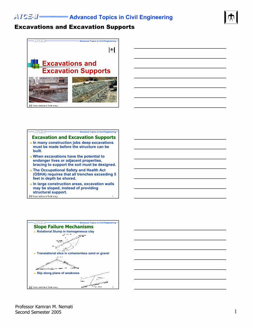
Slope Failure Mechanisms
� Translational slice in cohesionless sand or gravel
� Slip along plane of weakness
� Rotational Slump in homogeneous clay
Excavations and Excavation Supports
Advanced Topics in Civil EngineeringATCE-II ATCEATCEATCE---II II II
Professor Kamran M. NematiSecond Semester 2005 2
Advanced Topics in Civil EngineeringATCE-II ATCEATCEATCE---II II II
3
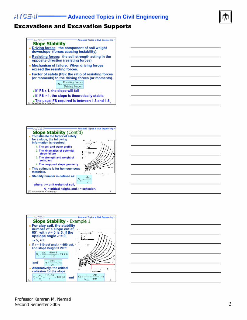
Slope Stability� Driving forces: the component of soil weight
downslope (forces causing instability).
� Resisting forces: the soil strength acting in the opposite direction (resisting forces).
� Mechanism of failure: When driving forces exceed the resisting forces.
� Factor of safety (FS): the ratio of resisting forces (or moments) to the driving forces (or moments).
� If FS ≤≤≤≤ 1, the slope will fail
� If FS > 1, the slope is theoretically stable.
� The usual FS required is between 1.3 and 1.5
Forces Driving
Forces ResistingFS =
Advanced Topics in Civil EngineeringATCE-II ATCEATCEATCE---II II II
4
Slope Stability (Cont’d)� To Estimate the factor of safety
for a slope, the following information is required:
1. The soil and water profile
2. The kinematics of potential slope failure
3. The strength and weight of soils, and
4. The proposed slope geometry.
� This estimate is for homogeneous materials.
� Stability number is defined as:
where: γ = unit weight of soil,
Hc = critical height, and c = cohesion.
c
HN c
S
γ=
Advanced Topics in Civil EngineeringATCE-II ATCEATCEATCE---II II II
5
Slope Stability - Example 1� For clay soil, the stability
number of a slope cut at 65°, with φ = 0 is 5, if the upslope angle α = 0,
ft 5.29110
5650=
×==
γs
c
cNH
� Alternatively, the critical cohesion for the slope
48.120
5.29FS ==
48.1440
650===
dReq'c
c FS
and
⇒⇒⇒⇒ Ns= 5
� If γ = 110 pcf and c = 650 psf, and slope height = 20 ft
5
psf 4405
20110=
×==
s
cc
N
HC
γand
Excavations and Excavation Supports
Advanced Topics in Civil EngineeringATCE-II ATCEATCEATCE---II II II
Professor Kamran M. NematiSecond Semester 2005 3
Advanced Topics in Civil EngineeringATCE-II ATCEATCEATCE---II II II
6
Slope Stability - Example 2
� If the cut described above is made to only 10 feet, what is the factor of safety of the slope against sliding?
ft 9.26110
55.4650=
×==
γs
c
cNH
7.28.241
650 FS ===
cc
cpsf 8.241
55.4
10110 =
×==⇒=
S
cc
c
cS
N
Hc
c
HN
γγ and
� A cut slope is to be made in a soft clay with its sides rising an angle of 75° to the horizontal. Given c = 650 psf and γ = 110 pcf.
� Determine the maximum depth up to which the excavation can be carried out.
From the graph: ⇒⇒⇒⇒ Ns = 4.55
4.55
Advanced Topics in Civil EngineeringATCE-II ATCEATCEATCE---II II II
7
Slope Stability (Cont’d)Theoretical Safe Heights for Homogeneous
Clay Cut Slope with Vertical Sides
� The slope failures are probable in shallow excavations only for very soft to medium homogeneous clays.
� By flattening the slope angle from 90° to 45°, significant improvement in the factor of safety for a slope of a given height can be achieved.
Soil
Consistency
Unconfined
Compressive
Strength,
qu (psf)
Cohesion, c
(psf)
Safe Height, H
(ft)
Very soft < 500 < 250 < 5
Soft 500 – 1000 250 – 500 5 –10
Medium 1000 – 2000 500 – 1000 10 – 20
Stiff 2000 – 4000 1000 – 2000 20 – 40
Very stiff 4000 – 8000 2000 – 4000 40 – 80
Hard > 8000 > 4000 > 80
Advanced Topics in Civil EngineeringATCE-II ATCEATCEATCE---II II II
8
Slope Protection� Temporary slope protection should be provided to
prevent sloughing of soil materials into the excavation, such as coating or other impervious material applied to the slope.
� To prevent slope erosion in rainstorms, spray-on product are used on silty soil materials to bind the soil particles on the surface.
� Plastic covering can be used to prevent changes in moisture content on the surface of the slope to maintain stability.
� Chain link fence can be draped over a slope surface, when the slope contains significant amount of loose large rocks.
Excavations and Excavation Supports
Advanced Topics in Civil EngineeringATCE-II ATCEATCEATCE---II II II
Professor Kamran M. NematiSecond Semester 2005 4
Advanced Topics in Civil EngineeringATCE-II ATCEATCEATCE---II II II
9
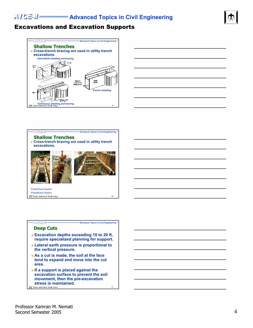
Shallow Trenches� Cross-trench bracing are used in utility trench
excavations.Intermittent sheeting and bracing
Continuous sheeting and bracing
Trench shielding
Advanced Topics in Civil EngineeringATCE-II ATCEATCEATCE---II II II
10
Shallow Trenches� Cross-trench bracing are used in utility trench
excavations.
PowerShore System
PowerBrace System
Advanced Topics in Civil EngineeringATCE-II ATCEATCEATCE---II II II
11
Deep Cuts
� Excavation depths exceeding 10 to 20 ft, require specialized planning for support.
� Lateral earth pressure is proportional to the vertical pressure.
� As a cut is made, the soil at the face tend to expand and move into the cut area.
� If a support is placed against the excavation surface to prevent the soil movement, then the pre-excavation stress is maintained.
Excavations and Excavation Supports
Advanced Topics in Civil EngineeringATCE-II ATCEATCEATCE---II II II
Professor Kamran M. NematiSecond Semester 2005 5
Advanced Topics in Civil EngineeringATCE-II ATCEATCEATCE---II II II
12
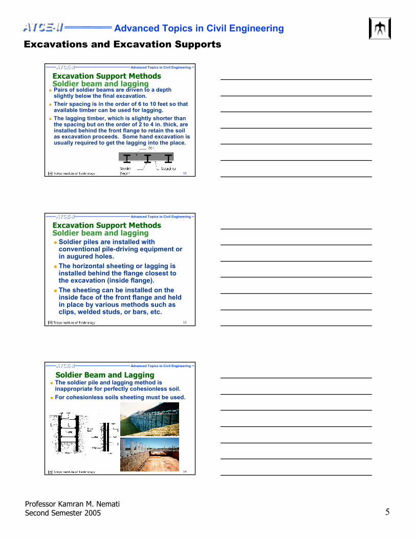
Excavation Support MethodsSoldier beam and lagging
� Pairs of soldier beams are driven to a depth slightly below the final excavation.
� Their spacing is in the order of 6 to 10 feet so that available timber can be used for lagging.
� The lagging timber, which is slightly shorter than the spacing but on the order of 2 to 4 in. thick, are installed behind the front flange to retain the soil as excavation proceeds. Some hand excavation is usually required to get the lagging into the place.
Advanced Topics in Civil EngineeringATCE-II ATCEATCEATCE---II II II
13
Excavation Support MethodsSoldier beam and lagging� Soldier piles are installed with
conventional pile-driving equipment or in augured holes.
� The horizontal sheeting or lagging is installed behind the flange closest to the excavation (inside flange).
� The sheeting can be installed on the inside face of the front flange and held in place by various methods such as clips, welded studs, or bars, etc.
Advanced Topics in Civil EngineeringATCE-II ATCEATCEATCE---II II II
14
Soldier Beam and Lagging � The soldier pile and lagging method is
inappropriate for perfectly cohesionless soil.
� For cohesionless soils sheeting must be used.
Excavations and Excavation Supports
Advanced Topics in Civil EngineeringATCE-II ATCEATCEATCE---II II II
Professor Kamran M. NematiSecond Semester 2005 6
Advanced Topics in Civil EngineeringATCE-II ATCEATCEATCE---II II II
15
Soldier Beam and Lagging
The soldier beam and lagging retaining wall
Workers install lagging
Advanced Topics in Civil EngineeringATCE-II ATCEATCEATCE---II II II
16
Soldier Beam and Lagging
Closeup of soldier beam and lagging
Soldier beam and lagging retaining wall
Advanced Topics in Civil EngineeringATCE-II ATCEATCEATCE---II II II
17
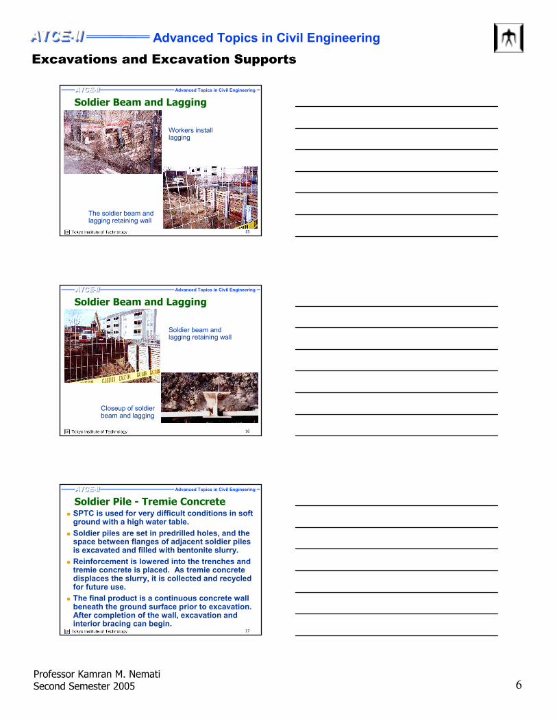
Soldier Pile - Tremie Concrete� SPTC is used for very difficult conditions in soft
ground with a high water table.
� Soldier piles are set in predrilled holes, and the space between flanges of adjacent soldier piles is excavated and filled with bentonite slurry.
� Reinforcement is lowered into the trenches and tremie concrete is placed. As tremie concrete displaces the slurry, it is collected and recycled for future use.
� The final product is a continuous concrete wall beneath the ground surface prior to excavation. After completion of the wall, excavation and interior bracing can begin.
Excavations and Excavation Supports
Advanced Topics in Civil EngineeringATCE-II ATCEATCEATCE---II II II
Professor Kamran M. NematiSecond Semester 2005 7
Advanced Topics in Civil EngineeringATCE-II ATCEATCEATCE---II II II
18
Soldier Pile - Tremie Concrete
Advanced Topics in Civil EngineeringATCE-II ATCEATCEATCE---II II II
19
Soldier Pile - Tremie Concrete
Typical free-
hanging
mechanical
clamshell for
slurry trench
excavation
Advanced Topics in Civil EngineeringATCE-II ATCEATCEATCE---II II II
20
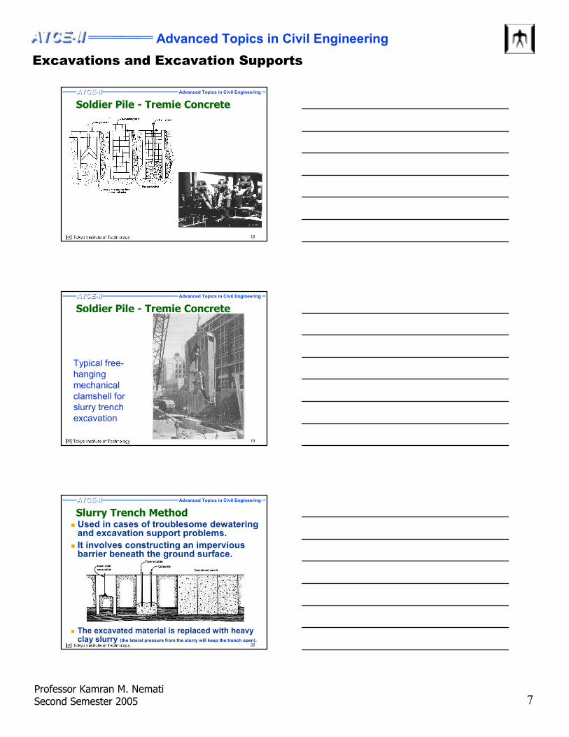
Slurry Trench Method� Used in cases of troublesome dewatering
and excavation support problems.
� It involves constructing an impervious barrier beneath the ground surface.
� The excavated material is replaced with heavy clay slurry (the lateral pressure from the slurry will keep the trench open).
Excavations and Excavation Supports
Advanced Topics in Civil EngineeringATCE-II ATCEATCEATCE---II II II
Professor Kamran M. NematiSecond Semester 2005 8
Advanced Topics in Civil EngineeringATCE-II ATCEATCEATCE---II II II
21
Slurry Trench Method (Cont’d)� After the excavation is completed,
concrete placement follows using tremie concrete method, from bottom to the top of excavation.
� As tremie concrete displaces the slurry, it is collected and recycled for future use.
� When the concrete is cured, the construction site is enclosed within a rigid, impervious barrier.
� This method has been employed to depths exceeding 200 feet.
Advanced Topics in Civil EngineeringATCE-II ATCEATCEATCE---II II II
22
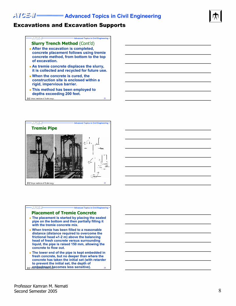
Tremie Pipe
Advanced Topics in Civil EngineeringATCE-II ATCEATCEATCE---II II II
23
Placement of Tremie Concrete� The placement is started by placing the sealed
pipe on the bottom and then partially filling it with the tremie concrete mix.
� When tremie has been filled to a reasonable distance (distance required to overcome the frictional head ≈≈≈≈1-2 m) above the balancing head of fresh concrete versus surrounding liquid, the pipe is raised 150 mm, allowing the concrete to flow out.
� The lower end of the pipe is kept embedded in fresh concrete, but no deeper than where the concrete has taken the initial set (with retarderto prevent the initial set, the depth of embedment becomes less sensitive).
Excavations and Excavation Supports
Advanced Topics in Civil EngineeringATCE-II ATCEATCEATCE---II II II
Professor Kamran M. NematiSecond Semester 2005 9
Advanced Topics in Civil EngineeringATCE-II ATCEATCEATCE---II II II
24
Placement of Tremie Concrete (Cont’d)� The tip of the tremie pipe should always be
immersed about 1 m as a minimum so as to prevent water inflow into the pipe.
� The flow of concrete should be smooth, consistent with the rate at which concrete can be delivered into the hopper at the top.
� The method of delivery should provide relatively even feed to the hopper rather than large batches being suddenly dumped.
� When large areas are to be covered, multiple tremie pipes should be used.
� The distance tremie can flow without excessive segregation is between 6 and 20 m.
Advanced Topics in Civil EngineeringATCE-II ATCEATCEATCE---II II II
25
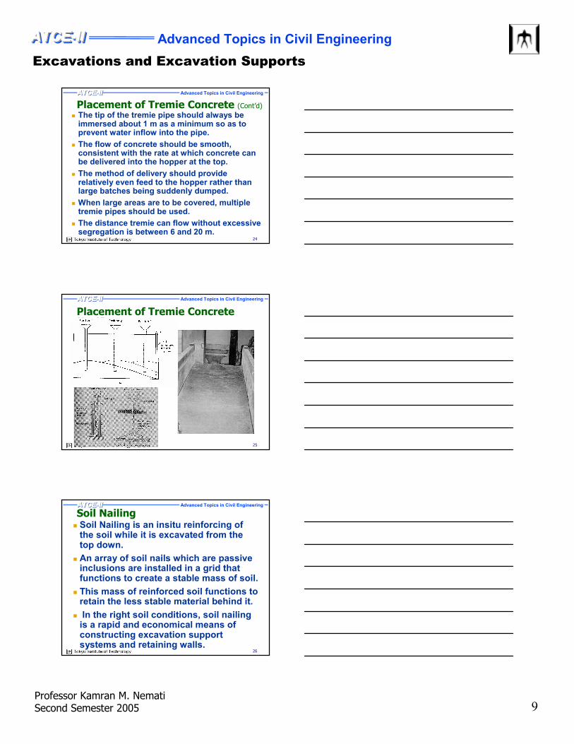
Placement of Tremie Concrete (Cont’d)
Advanced Topics in Civil EngineeringATCE-II ATCEATCEATCE---II II II
26
Soil Nailing� Soil Nailing is an insitu reinforcing of
the soil while it is excavated from the top down.
� An array of soil nails which are passive inclusions are installed in a grid that functions to create a stable mass of soil.
� This mass of reinforced soil functions to retain the less stable material behind it.
� In the right soil conditions, soil nailing is a rapid and economical means of constructing excavation support systems and retaining walls.
Excavations and Excavation Supports
Advanced Topics in Civil EngineeringATCE-II ATCEATCEATCE---II II II
Professor Kamran M. NematiSecond Semester 2005 10
Advanced Topics in Civil EngineeringATCE-II ATCEATCEATCE---II II II
27
Soil Nailing� In many applications soil nailing can be
the least disruptive way to construct a retaining wall.
� Soil nailing requires a unusual amount of hand work, craftsmanship and geotechnical knowledge to construct.
� The typical construction sequence begins with the excavation of a shallow cut. Then shotcrete is applied to the face of the cut and soil nails are drilled and grouted. This sequence is then repeated until subgrade is reached.
Advanced Topics in Civil EngineeringATCE-II ATCEATCEATCE---II II II
28
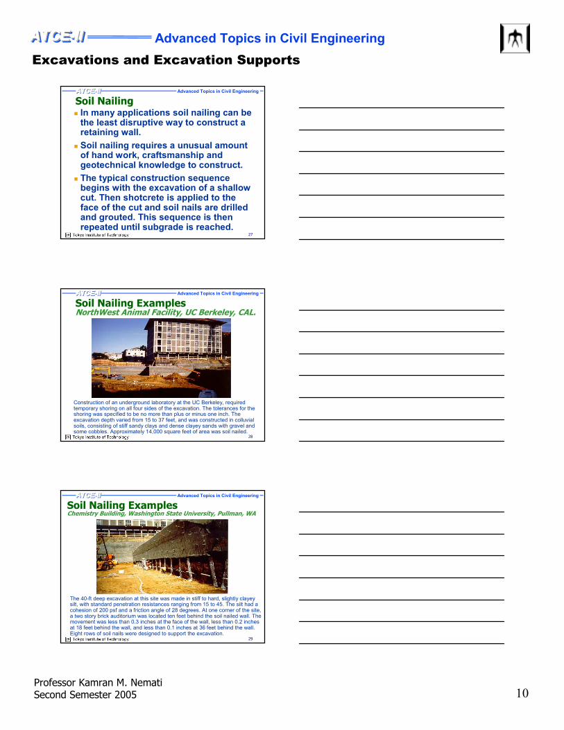
Soil Nailing ExamplesNorthWest Animal Facility, UC Berkeley, CAL.
Construction of an underground laboratory at the UC Berkeley, required temporary shoring on all four sides of the excavation. The tolerances for the shoring was specified to be no more than plus or minus one inch. The excavation depth varied from 15 to 37 feet, and was constructed in colluvialsoils, consisting of stiff sandy clays and dense clayey sands with gravel and some cobbles. Approximately 14,000 square feet of area was soil nailed.
Advanced Topics in Civil EngineeringATCE-II ATCEATCEATCE---II II II
29
Soil Nailing ExamplesChemistry Building, Washington State University, Pullman, WA
The 40-ft deep excavation at this site was made in stiff to hard, slightly clayey silt, with standard penetration resistances ranging from 15 to 45. The silt had a cohesion of 200 psf and a friction angle of 28 degrees. At one corner of the site, a two story brick auditorium was located ten feet behind the soil nailed wall. The movement was less than 0.3 inches at the face of the wall, less than 0.2 inches at 18 feet behind the wall, and less than 0.1 inches at 36 feet behind the wall. Eight rows of soil nails were designed to support the excavation.
Excavations and Excavation Supports
Advanced Topics in Civil EngineeringATCE-II ATCEATCEATCE---II II II
Professor Kamran M. NematiSecond Semester 2005 11
Advanced Topics in Civil EngineeringATCE-II ATCEATCEATCE---II II II
30
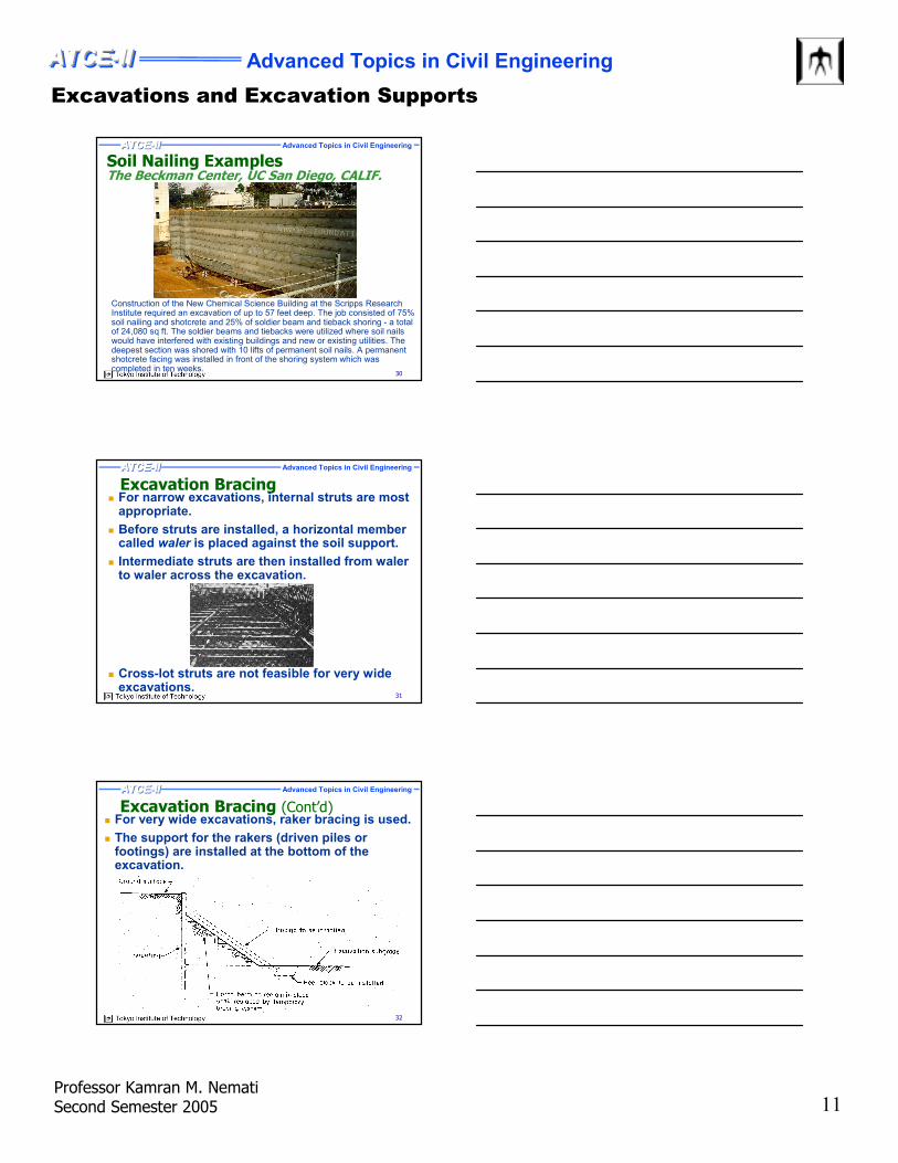
Soil Nailing ExamplesThe Beckman Center, UC San Diego, CALIF.
Construction of the New Chemical Science Building at the Scripps Research Institute required an excavation of up to 57 feet deep. The job consisted of 75% soil nailing and shotcrete and 25% of soldier beam and tieback shoring - a total of 24,080 sq ft. The soldier beams and tiebacks were utilized where soil nails would have interfered with existing buildings and new or existing utilities. The deepest section was shored with 10 lifts of permanent soil nails. A permanent shotcrete facing was installed in front of the shoring system which was completed in ten weeks.
Advanced Topics in Civil EngineeringATCE-II ATCEATCEATCE---II II II
31
Excavation Bracing� For narrow excavations, internal struts are most
appropriate.
� Before struts are installed, a horizontal member called waler is placed against the soil support.
� Intermediate struts are then installed from walerto waler across the excavation.
� Cross-lot struts are not feasible for very wide excavations.
Advanced Topics in Civil EngineeringATCE-II ATCEATCEATCE---II II II
32
Excavation Bracing (Cont’d)� For very wide excavations, raker bracing is used.
� The support for the rakers (driven piles or footings) are installed at the bottom of the excavation.
Excavations and Excavation Supports
Advanced Topics in Civil EngineeringATCE-II ATCEATCEATCE---II II II
Professor Kamran M. NematiSecond Semester 2005 12
Advanced Topics in Civil EngineeringATCE-II ATCEATCEATCE---II II II
33
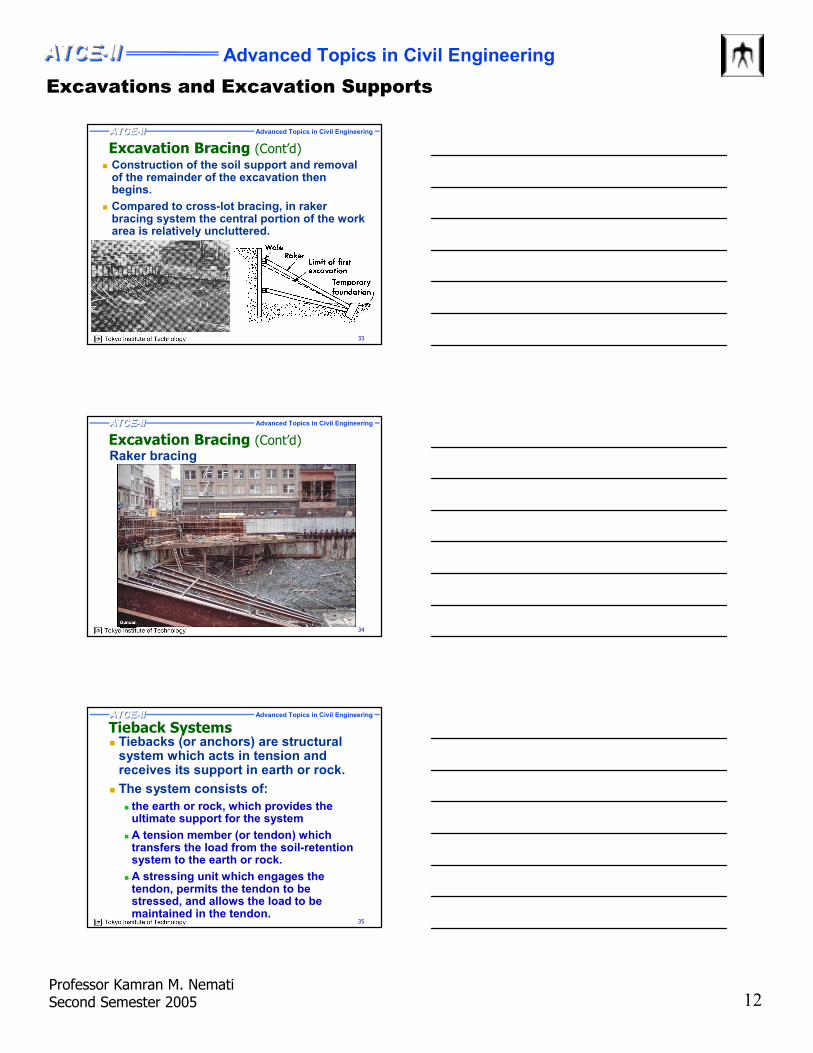
Excavation Bracing (Cont’d)� Construction of the soil support and removal
of the remainder of the excavation then begins.
� Compared to cross-lot bracing, in rakerbracing system the central portion of the work area is relatively uncluttered.
Advanced Topics in Civil EngineeringATCE-II ATCEATCEATCE---II II II
34
Excavation Bracing (Cont’d)Raker bracing
Advanced Topics in Civil EngineeringATCE-II ATCEATCEATCE---II II II
35
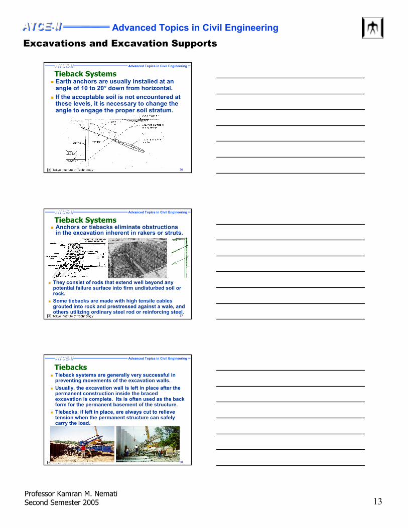
Tieback Systems� Tiebacks (or anchors) are structural
system which acts in tension and receives its support in earth or rock.
� The system consists of:
� the earth or rock, which provides the ultimate support for the system
� A tension member (or tendon) which transfers the load from the soil-retention system to the earth or rock.
� A stressing unit which engages the tendon, permits the tendon to be stressed, and allows the load to be maintained in the tendon.
Excavations and Excavation Supports
Advanced Topics in Civil EngineeringATCE-II ATCEATCEATCE---II II II
Professor Kamran M. NematiSecond Semester 2005 13
Advanced Topics in Civil EngineeringATCE-II ATCEATCEATCE---II II II
36
Tieback Systems� Earth anchors are usually installed at an
angle of 10 to 20° down from horizontal.
� If the acceptable soil is not encountered at these levels, it is necessary to change the angle to engage the proper soil stratum.
Advanced Topics in Civil EngineeringATCE-II ATCEATCEATCE---II II II
37
Tieback Systems� Anchors or tiebacks eliminate obstructions
in the excavation inherent in rakers or struts.
� They consist of rods that extend well beyond any potential failure surface into firm undisturbed soil or rock.
� Some tiebacks are made with high tensile cables grouted into rock and prestressed against a wale, and others utilizing ordinary steel rod or reinforcing steel.
Advanced Topics in Civil EngineeringATCE-II ATCEATCEATCE---II II II
38
Tiebacks� Tieback systems are generally very successful in
preventing movements of the excavation walls.
� Usually, the excavation wall is left in place after the permanent construction inside the braced excavation is complete. Its is often used as the back form for the permanent basement of the structure.
� Tiebacks, if left in place, are always cut to relieve tension when the permanent structure can safely carry the load.
Excavations and Excavation Supports
Advanced Topics in Civil EngineeringATCE-II ATCEATCEATCE---II II II
Professor Kamran M. NematiSecond Semester 2005 14
Advanced Topics in Civil EngineeringATCE-II ATCEATCEATCE---II II II
39
Tieback ExamplesTwo Renaissance Square, Phoenix, AZ
This is a 63-foot deep tiedback excavation. The subsurface material through which this major excavation was installed consisted of 25 feet of medium dense to dense sands and gravel, underlain by very dense sand, gravel and cobbles (SGC). The SGC contained a large percentage of cobbles up to 18 inches in diameter. The job consisted of 62,000 square feet of shoring and 500 tiebacks.
Advanced Topics in Civil EngineeringATCE-II ATCEATCEATCE---II II II
40
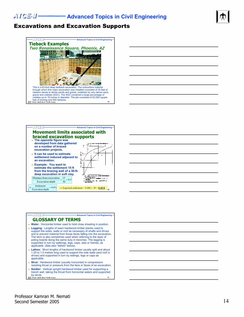
Movement limits associated with braced excavation supports
� The opposite figure was developed from data gathered on a number of braced excavation projects.
� It can be used to estimate settlement induced adjacent to an excavation.
� Example: You want to estimate the settlement 15 ft from the bracing wall of a 30-ft-deep excavation in soft clay.
0.5
0.6
5.030
15
depth Excavation
excavation from Distance==
%6.0depth Excavation
Settlement=⇒ ⇒ Expected settlement = 0.006 × 30 = 0.18 ft
Advanced Topics in Civil EngineeringATCE-II ATCEATCEATCE---II II II
41
GLOSSARY OF TERMS� Waler: Horizontal timber used to hold close sheeting in position.
� Lagging: Lengths of sawn hardwood timber planks used to support the sides, walls or roof as necessary of shafts and drives and to prevent material from those faces falling into the excavation. The term is also sometimes used when referring to the layer of poling boards doing the same duty in trenches. The lagging is supported in turn by walkings, legs, caps, sets or frames, as applicable. (See also "lathes" below).
� Lathes: Short lengths of hardwood timber usually split and about 1.25 to 1.5 metres long used to support the side walls (and roof in drives) and supported in turn by walings, legs or caps as applicable.
� Strut: Hardwood timber (usually horizontal) in compression resisting thrust or pressure from the face or faces of an excavation.
� Soldier: Vertical upright hardwood timber used for supporting a trench wall, taking the thrust from horizontal walers and supported by struts.