Embed Size (px)
Citation preview
lable at ScienceDirect
Renewable Energy 39 (2012) 114e125
Contents lists avai
Renewable Energy
journal homepage: www.elsevier .com/locate/renene
Exergetic analysis of solar concentrator aided natural gas fired combinedcycle power plant
V. Siva Reddy a,*, S.C. Kaushik a, S.K. Tyagi b
aCentre for Energy Studies, Indian Institute of Technology Delhi, Hauz Khas, New Delhi 110016, Indiab Sardar Swaran Singh National Institute of Renewable Energy, Jalandhar-Kapurthala Road, Wadala Kalan, Kapurthala, 144601 Punjab, India
a r t i c l e i n f o
Article history:Received 16 February 2011Accepted 20 July 2011Available online 1 September 2011
Keywords:Energetic efficiencyExergetic efficiencyCombined cycleSolar aidedLFRSC
* Corresponding author. þ91 9891742963.E-mail address: [email protected] (V. Siva Re
0960-1481/$ e see front matter � 2011 Elsevier Ltd.doi:10.1016/j.renene.2011.07.031
a b s t r a c t
This article deals with comparative energy and exergetic analysis for evaluation of natural gas firedcombined cycle power plant and solar concentrator aided (feed water heating and low pressure steamgeneration options) natural gas fired combined cycle power plant. Heat Transfer analysis of LinearFresnel reflecting solar concentrator (LFRSC) is used to predict the effect of focal distance and width ofreflector upon the reflecting surface area. Performance analysis of LFRSC with energetic and exergeticmethods and the effect, of concentration ratio and inlet temperature of the fluid is carried out todetermine, overall heat loss coefficient of the circular evacuated tube absorber at different receivertemperatures. An instantaneous increase in power generation capacity of about 10% is observed bysubstituting solar thermal energy for feed water heater and low pressure steam generation. It is observedthat the utilization of solar energy for feed water heating and low pressure steam generation is moreeffective based on exergetic analysis rather than energetic analysis. Furthermore, for a solar aided feedwater heating and low pressure steam generation, it is found that the land area requirement is 7 ha/MWfor large scale solar thermal storage system to run the plant for 24 h.
� 2011 Elsevier Ltd. All rights reserved.
1. Introduction
Growing demand of power and degradation of environment hasmade the power plants of scientific interest for the efficient utili-zation of energy resources. India faces a significant gap betweenelectricity demand and supply as reported by the Central ElectricityAuthority for the year 2009e2010 as almost 84 TWh, which is 10%of the total requirement. The peak demand deficit is more than15 GW, corresponding to a shortage of 12.7% [1]. The total powergeneration capacity of India now is 167.01 � 103 MW (Dec 2010).Out of that natural gas fired combined cycle power plants have thegeneration capacity of 17.38� 103MWwhich is about 10% [2]. Indiahas a rich solar energy resource and the average intensity of solarradiation received in India is 200 MW/km2. Using the free availablesolar energy in the existed thermal power plant for feed waterheating and low pressure steam generation can reduce not only theglobal warming problems but also can save the high share ofnatural energy resource. Srinivas [3] concentrated on improve-ments in the performance of a triple pressure combined cycle witha deaerator location. Deaerator placed between the low pressure
ddy).
All rights reserved.
and intermediate pressure heaters, gives high efficiency comparedto a deaerator-condenser arrangement. Reddy et al. [4] performedexergy analysis of a natural gas fired combined cycle powergeneration unit to investigate the effect of gas turbine inlettemperature and pressure ratio on exergetic efficiency for the plantand exergy destruction/losses for the components. Srinivas et al. [5]present the analysis of the gas cycle in which a topping cycle hasbeen separately compared with the effects of intercooling andreheating on the performance of the combined cycle power plant.
Khaliq and Kaushik [6] evaluated second law analysis of thereheat combined Brayton/Rankine power cycle. Negi et al. [7]presented optical designs and performance characteristics of anLFRC with a flat vertical absorber by two different approaches withand without varying the width of the constituent mirror elements.Further Negi et al. [8] experimentally determined the optical effi-ciency of the concentrator with different types of absorptive coat-ings. Singh et al. [9] analyzed the thermal performance of the fouridentical trapezoidal cavity absorbers for linear Fresnel reflectingsolar device. Singh et al. [10] also determined the overall heat losscoefficients of the trapezoidal cavity absorber with rectangular andround pipe in the laboratory. The results show that a double glasscover reduces the heat loss coefficient by 10e15% as compared toa single glass cover. Facao and Oliveira [11] analyzed and optimizeda new trapezoidal cavity receiver for a linear Fresnel solar collector

V. Siva Reddy et al. / Renewable Energy 39 (2012) 114e125 115
via ray-trace and CFD simulations. Gupta and Kaushik [12] havecarried out a comparative study of a typical 50 kW solar thermalpower plant and a 220 MW coal fired solar aided thermal powerplant. It has been found that the efficiency of work conversion ofsolar aided thermal energy in coal fired thermal power plant ishigher than that of the efficiency of work conversion in solarthermal power plant. In the similar passion The performance ofsolar thermal aided in coal fired power plants to establish theirtechno-economic viability of subcritical and supercritical powerplant being commissioned in India was carried out by Reddy et al.[13]. Popov [14] has modeled Rankine regenerative steam cyclepower plant by involving solar thermal energy to replace the heatproduced by fossil fuels.
In this paper detailed exergetic analysis procedure for naturalgas fired combined cycle power plant and for LFRSC has beenpresented. The overall heat loss coefficients of the circular evacu-ated tube absorber for various receiver temperatures have beendetermined. Also the solar aided options for feed water heating andlow pressure steam generation for natural gas fired combined cyclepower plant with both exegetic and energetic methods has beenanalyzed and the performance of combined cycle power plant withand without solar aided was evaluated.
2. Description and exergetic analysis of gas fired combinedcycle power plant
Considered plant consists of two gas turbine based units andone multi-pressure heat recovery steam generator unit. Thesymbols identifying the streams and state point properties aredescribed in Table 1. Process descriptions reported previously [4,15]for each unit is summarized. Detailed flow diagram of gas firedcombined cycle power plant is shown in Fig. 1. It is clear from Fig. 1that air is compressed from state point 1e2 and (1le2l) incompressor (C) and this compressed air turn to combustionchamber (CC) where combustion takes place (2e3) and (2le3l).After combustion, the combustion products enter into gas turbine(GT) where expansion take place (3e4) and (3le4l). The flue gasespassing through heat recovery steam generator (HRSG) system
Table 1Stream data for Natural Gas Fired Combined Cycle Power Plant.
Stream Points Fluid Mass flow(kg/s)
Temperature(K)
Pressure(bar)
1 Air 360 302 1.0131l Air 360 302 1.0132 Air 360 637 10.221 Air 360 637 10.23 Flue gas 366 1345 9.631 Flue gas 366 1345 9.64 Flue gas 366 824 1.1041 Flue gas 366 824 1.105 Water 51.73 321.105 3.6451 Water 51.73 321.105 3.646 Water 79.57 345.24 3.6461 Water 79.57 345.24 3.647 Water 79.57 409.42 3.6471 Water 79.57 409.42 3.648 Water 43.97 410.4 72.681 Water 43.97 410.4 72.69 Steam 87.95 791.23 55.2510 Steam 87.95 479.68 5.611 Water 10.34 409.7 21.3111 Water 10.34 409.7 21.312 Steam 10.34 474.32 5.613 Steam 103.47 474.32 5.614 Steam 103.47 323 0.123515 Water 103.47 321 0.112316 Flue gas 366 383 1.013161 Flue gas 366 383 1.013
(4e16 and 4l�16l) and transferring the heat to feed water for steamgeneration. In the steam power generation unit, condensed steamextracted from state point 15 and pumped to deaerator (7 and 7l)through feed water heater by condensate extract pump (CEP).There are two feed pumps (i) low pressure feed water pump (LFP)and (ii) high pressure feed water pump (HEP). These pumps areresponsible to supply feed water into respective steam generationunits. High pressure steam expanded into high pressure steamturbine (HPT) with state point 9e10. After expansion in HPT, thesteam mixed with low pressure steam at state point 12. The lowpressure steam expanded low pressure steam turbine (LPT) at statepoint 13e14. The whole power generation cycle with different statepoints is depicted with TeS diagram in Fig. 2. It reveals the actualcycle process takes place during power generation. Using theenergy balance and mass equations for each component in thepower plant, energy/exergy flows and at each node of the plant canbe calculated analytically as well as numerically, for given set ofoperating conditions.
2.1. Exergetic analysis of natural gas fired combined cycle powerplant
In an open flow system there are three types of energy transferacross the control surface namely work transfer, heat transfer, andenergy associated with mass transfer and/or flow energy. The firstlaw of thermodynamics or energy conservation equation for thesteady flow process of an open system is given by:
X_Qk þ _m
hi þ
c2i2þ gZi
!¼ _m
�ho þ c2o
2þ gZo
�þ _W (1)
The energetic or first law efficiency hI of a system and/or systemcomponent is defined as the ratio of energy output to the energyinput to system/component i.e.
hI ¼ Desired output energyInput energy supplied
(2)
SP. Enthalpy(kJ/kg)
SP. Entropy(kJ/kg.K)
Energetic power(kW)
Exergetic power(kW)
428.20 3.8916 308.30 � 103 20.52428.20 3.8916 308.30 � 103 20.52772.45 3.9918 556.16 � 103 226.30 � 103
772.45 3.9918 556.16 � 103 226.30 � 103
1.48 � 103 7.6409 106.90 � 104 624.97 � 103
1.48 � 103 7.6409 106.90 � 104 624.97 � 103
872.96 7.6731 639.01 � 103 180.54 � 103
872.96 7.6731 639.01 � 103 180.54 � 103
201.72 0.679 20.87 � 103 373.8201.72 0.679 20.87 � 103 373.8302.72 0.9821 48.18 � 103 2.214 � 103
302.72 0.9821 48.18 � 103 2.214 � 103
573.85 1.702 91.32 � 103 11.094 � 103
573.85 1.702 91.32 � 103 11.094 � 103
582.56 1.7052 51.24 � 103 6.813 � 103
582.56 1.7052 51.24 � 103 6.813 � 103
3.4 �103 6.9809 305.39 � 103 122.09 � 103
2867.2 7.034 252.17 � 103 67.54 � 103
576.2 1.7031 11.91 � 103 1.48 � 103
576.2 1.7031 11.91 � 103 1.48 � 103
2.86 �103 7.0097 59.03 � 103 15.79 � 103
2.86 �103 7.0097 295.46 � 103 79.01 � 103
2.28 �103 7.1227 236.28 � 103 16.33 � 103
200.98 0.6778 20.79 � 103 334.4318.11 6.6428 83.62 �103 7.56 � 103
318.11 6.6428 83.62 � 103 7.56 � 103

Air
FuelFuel
16
Air
1
CC
Deaerator
HRSG2
G
CC
16 l
HP-Drum1
LP-Drum2 LP-Drum1
HP-Drum2
CEP1 CEP2
HFP1
LFP1
LFP2
HFP2
HRSG1
23
41 l
2 l 3 l
4 l
5 6
7
8
9
10
11
12 l
155 l6 l
7 l
8 l
11 l Condenser
13 12
GT.1
14
Hp-Supp Hp-Supp
Hp-Evap Hp-Evap
Hp-Econ2 Hp-Econ2
Hp-Econ1 Hp-Econ1
CPH CPH
Lp-Econ Lp-Econ
Lp-Evap Lp-Evap
Lp-SuppLp-Supp
FWH 1 FWH 2
b
a
c
d
c
d
GT.2 C C
LPT LPTHPT
G G
Fig. 1. Natural Gas Fired Combined Cycle Power Plant.
V. Siva Reddy et al. / Renewable Energy 39 (2012) 114e125116
Exergy is a generic term that defines the maximum possiblework potential of a system from a stream of matter and/or heatinteraction; with respect to the state of the environment being usedas the datum state. The Exergy (JQ) of heat transfer Q from thecontrol surface at temperature T is determined frommaximum rateof conversion of thermal energy to work Wmax as given by:
Wmax ¼ JQ ¼ Q�1� To
T
�(3)
1,1l
2,2l
4,4l
6,6l
b 7,7l
8,8l
11,11l
9
14
5,5l
10, 12,12l, 13
15
3,3l
16, 16l
T
S
•
Fig. 2. TeS diagram of Natural Gas Fired Combined Cycle Power Plant.
Exergy of steady flow stream of matter is the sum of kinetic,potential and physical exergy. The kinetic and potential energy arealmost equivalent to exergy. Exergetic analysis is a method thatuses the conservation of mass and degradation of the quality ofenergy along with the entropy generation in the analysis designand improvement of energy systems. Exergetic analysis is a usefulmethod; to complement but not to replace energetic analysis.
The exergy flow for steady flow process of an open system isgiven by
X�1� To
Tk
�Qk þ
Xin
_mJi ¼ JW þXout
_mJo þ _Idestroyed (4)
J ¼ _mh�
h0 � h0o�� T0ðs� s0Þ
i(5)
h0 ¼ hþ C2
2þ gZ (6)
_Idestroyed ¼ T0 _sgen (7)
The physical specific exergyJi andJo depends on initial state ofmatter and environmental state. The irreversibility may be due toheat transfer through finite temperature difference, mixing of fluidsat different temperature and mechanical friction. Exergetic analysisis an effective means, to pinpoint losses due to irreversibility ina real situation.
The exergetic or second law efficiency is defined as
hII ¼ Actual thermal efficiencymaximum possible ðreversibleÞthermal efficiency
¼ Exergy outputExergy input
¼ 1� Exergy LossExergy Input
(8)
V. Siva Reddy et al. / Renewable Energy 39 (2012) 114e125 117
(a) The exergy balance for Combustion chamber
The exergy balance for the Combustion is give by:
0 ¼Xrk¼1
h�_mJ�gþa�
�_mJ�p
ik�T0 _sgen (9)
Where mfþa is sum of the mass of gas and air, mp is products aftercombustion.
which gives:
T0 _Sgen ¼h�
_mJ�gþa�
�_mJ�p
i(10)
Chemical exergy of the compressed nature gas (CNG) is given inappendix B.
The exergetic efficiency is defined as
hII;CC ¼ 1� T0 _sgenð _mJÞgþa
¼�_mJ�p
ð _mJÞgþa(11)
(b) The exergy balance for Gas turbine:
WGT ¼ _m3ðJ3 �J4Þ � T0 _sgen (12)
The irreversibility ¼ exergy loss is:
_Idestroyed ¼ T0 _sgen ¼ T0 _m3ðs4 � s3Þ (13)
The exergetic efficiency is:
hII;GT ¼ 1�_Idestroyed
_m3ðJ3 �J4Þ¼ WGT
_m3ðJ3 �J4Þ(14)
(c) The exergy balance for Air Compressor:
�WC ¼ _m1ðJ1 �J2Þ � T0 _sgen (15)
The irreversibility ¼ exergy loss is:
_Idestroyed ¼ T0 _sgen ¼ _m1T0ðs2 � s1Þ (16)
The exergetic efficiency is:
hII;C ¼ 1�_Idestroyed
WC¼ _m1ðJ2 �J1Þ
WC(17)
(d) The exergy balance for heat recovery steam generator (HRSG)
The performance of the HRSG strongly affects the overallperformance of the combined cycle power plant. HRSG is nothingbut shall and tube heat exchanger, in that hot gas flow through theshell and water flow thorough tubes.
The exergy flow equation for the boiler heat exchangerbecomes:
0 ¼ _mgþaðJ4�J16Þ� _m6ðJ7�J6Þ� _m11ðJ12�J11Þ� _m8ðJ9�J8Þ�T0 _sgen (18)
The irreversibility ¼ exergy loss ish�
_Idestroyed ¼ T0 _sgen ¼ _mfþaðh4�h16Þ� _m6ðh7�h6Þ� _m11ðh12�h11Þ� _m8ðh9�h8Þ��T0
�_mgþaðs4� s16Þ
� _m6ðs7� s6Þ� _m8ðs9� s8Þ� _m11ðs12� s11Þ�i ð19Þ
The second law efficiency is:
hII;HRSG ¼ 1�_Idestroyed
_mgþaðJ4 �J16Þ
¼ _m6ðJ7 �J6Þ þ _m11ðJ12 �J11Þ þ _m8ðJ9 �J8Þ_mgþaðJ4 �J16Þ
(20)
2.1.1. Pumps used in steam power cycle
(e) The exergy balance for Condensate extract pumps (CEP):
�WCEP ¼ _m1ðJ15 �J5Þ � T0 _sgen (21)
The irreversibility ¼ exergy loss is:
_Idestroyed ¼ T0 _sgen ¼ _m1ðJ15 �J5Þ þWCEP ¼ _m1T0ðs5 � s15Þ(22)
The exergetic efficiency is:
hII;CEP ¼ 1�_IdestroyedWCEP
¼ _m1ðJ5 �J15ÞWCEP
(23)
(f) The exergy balance for High pressure feed water pump (HFP):
�WHFP ¼ _m7ðJ7 �J8Þ � T0 _sgen (24)
The irreversibility ¼ exergy loss is:
_Idestroyed ¼ T0 _sgen ¼ _m7ðJ7�J8ÞþWLpp ¼ _m7T0ðs8� s7Þ (25)
The exergetic efficiency is:
hII;HFP ¼ 1�_IdestroyedWHFP
¼ _m1ðJ8 �J7ÞWHFP
(26)
(g) The exergy balance for Low pressure feed water pump (LFP):
�WLFP ¼ _m7ðJ7 �J11Þ � T0 _sgen (27)
The irreversibility ¼ exergy loss is:
_Idestroyed ¼ T0 _sgen ¼ _m7ðJ7 �J11Þ þWLpp ¼ _m7T0ðs11 � s7Þ(28)
The exergetic efficiency is:
hII;LFP ¼ 1�_IdestroyedWLFP
¼ _m1ðJ11 �J7ÞWLFP
(29)
2.1.2. Steam turbine subsystem
(h) The exergy balance for High pressure steam turbine (HPT):
�WHPT ¼ _m9ðJ9 �J10Þ � T0 _sgen (30)
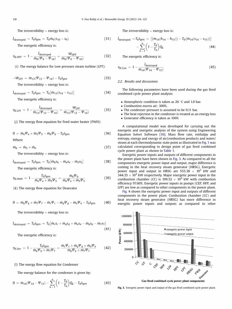
Fig. 3. Energetic power input and output of the gas fired combined cycle power plant.
V. Siva Reddy et al. / Renewable Energy 39 (2012) 114e125118
The irreversibility ¼ exergy loss is:
_Idestroyed ¼ T0 _sgen ¼ T0 _m9ðs10 � s9Þ (31)
The exergetic efficiency is:
hII;HPT ¼ 1�_Idestroyed
_m9ðJ9 �J10Þ¼ WHPT
_m9ðJ9 �J10Þ(32)
(i) The exergy balance for Low pressure steam turbine (LPT):
�WLPT ¼ _m13ðJ13 �J14Þ � T0 _sgen (33)
The irreversibility ¼ exergy loss is:
_Idestroyed ¼ T0 _sgen ¼ T0�_m13ðs14 � s13Þ
(34)
The exergetic efficiency is:
hII;LPT ¼ 1�_Idestroyed
_m13ðJ13 �J14Þ¼ WLPT
_m13ðJ13 �J14Þ(35)
(j) The exergy flow equation for Feed water heater (FWH):
0 ¼ _maJa þ _m5J5 � _m6J6 � T0 _sgen (36)
Where
_m6 ¼ _m5 þ _ma (37)
The irreversibility ¼ exergy loss is:
_Idestroyed ¼ T0 _sgen ¼ T0�_m6s6 � _masa � _m5s5
(38)
The exergetic efficiency is:
hII;FWH ¼ 1� T0 _sgen_maJa þ _m5J5
¼ _m6J6_maJa þ _m5J5
(39)
(k) The exergy flow equation for Deaerator
0 ¼ _mbJb þ _m7J7 � _mcJc � _mdJd � _maJa � T0 _sgen (40)
The irreversibility ¼ exergy loss is:
_Idestroyed ¼ T0 _sgen ¼ T0�_mcsc þ _mdsd þ _masa � _mbsb � _m7s7
(41)
The exergetic efficiency is:
hII;Der ¼ 1� T0 _sgen_mbJb þ _m7J7
¼ _mcJc þ _mdJd þ _maJa_mbJb þ _m7J7
(42)
(l) The exergy flow equation for Condenser
The exergy balance for the condenser is given by:
0 ¼ _m14ðJ14 �J15Þ �Xnk¼1
�1� T0
Tk
�Qk � T0 _sgen (43)
The irreversibility ¼ exergy loss is:
_Idestroyed ¼ T0 _sgen ¼ ��_m14ðh14 � h15Þ
�� T0�_m14ðs14 � s15Þ
��Xnk¼1
�1� T0
Tk
�Qk ð44Þ
The exergetic efficiency is:
hII;Con ¼ 1�_Idestroyed
_m14ðJ14 �J15Þ(45)
2.2. Results and discussions
The following parameters have been used during the gas firedcombined cycle power plant analysis:
� Atmospheric condition is taken as 26 �C and 1.0 bar.� Combustion excess air: 300%.� The condenser pressure is assumed to be 0.11 bar.� The heat rejection in the condenser is treated as an energy loss� Generator efficiency is taken as 100%
A computational model was developed for carrying out theenergetic and exergetic analysis of the system using EngineeringEquation Solver Software [16]. Mass flow rate, enthalpy andentropy, energy and exergy of air/combustion products and water/steam at each thermodynamic state point as illustrated in Fig. 1 wascalculated corresponding to design point of gas fired combinedcycle power plant as shown in Table 1.
Energetic power inputs and outputs of different components inthe power plant have been shown in Fig. 3. As compared to all thecomponents energetic power input and output, major difference iscoming in the heat recovery steam generator (HRSG). Energeticpower input and output in HRSG are 555.38 � 103 kW and344.35 � 103 kW respectively. Major energetic power input in thecombustion chamber (CC) is 109.52 � 104 kW with combustionefficiency 97.60%. Energetic power inputs in pumps (CEP, HFP, andLFP) are low as compared to other components in the power plant.
Fig. 4 shows the exergetic power input and outputs of differentcomponents in the power plant. Combustion chamber (CC) andheat recovery steam generator (HRSG) has more difference inexergitic power inputs and outputs as compared to other

Fig. 4. Exergetic power input and output of the gas fired combined cycle power plant.
V. Siva Reddy et al. / Renewable Energy 39 (2012) 114e125 119
components. Exergetic power input and output in CC are770.73 � 103 kW and 624.97 � 103 kW respectively. Exergeticpower input and output in HRSG are 172.97 � 103 kW and138.46 � 103 kW respectively.
Exergetic and energetic power losses of different components inthe power plant have been shown in Fig. 5. Among the allcomponents combustion chamber (CC) havemajor exergetic powerloss 145.76 � 103 kWwhile energetic power loss is 26.22 � 103 kW.Heat recovery steam generators (HRSG) have more energy loss of211.03 � 103 kW and exergetic power loss of 34.51 � 103 kW. Incondenser energetic power loss is as high as 215.48 � 103 kW ascompared to the exergetic power loss of 16.00 � 103 kW. But in theturbines (HPT, LPT, and GT) and pumps (CEP, HFP, and LFP) energeticand exergetic power losses are much less in magnitude.
By the energetic analysis in natural gas fired combined cyclepower plant major energetic power loss in condenser followed byheat recovery steam generator (HRSG). But, exergetic analysisshowsmajor exergetic power loss in combustion chamber followedby heat recovery steam generator (HRSG). So increasing thecapacity of combined cycle power plant by increasing fuel inputitself is inefficient. So, alternate method of heat energy input is
Fig. 5. Exergetic and energetic power loss for the Gas fired combined cycle powerplant.
required to increase the capacity of the power plant. Furtheranalysis has been done upon exergetic analysis of Linear FresnelReflecting Solar Concentrator (LFRSC), solar aided feed waterheating and low pressure steam generation system.
3. Description and exergetic analysis of linear Fresnelreflecting solar concentrator (LFRSC)
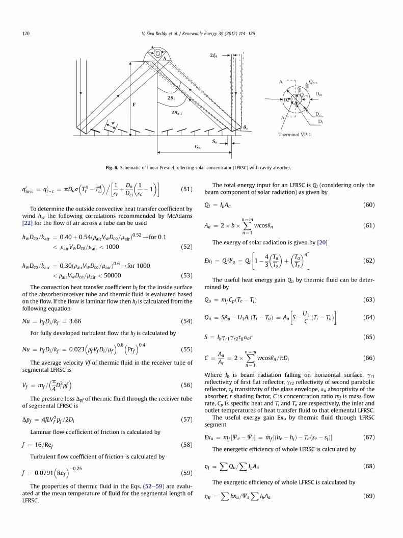
The linear Fresnel principle allows focusingwith the aid of manyflat mirrors set up on the ground which are individually adjustable.Mirrors follow the position of the Sun by rotating around their longaxes so that they point to a focus line at a several meters heightwhich remains fixed over time. LFRSC with parabolic cavity assecond reflector and a circular tube absorber evacuated by glasstube is schematically shown in Fig. 6. An equal width (W) of theconstituent mirror elements was considered in each case. The tilt ofeach constituent mirror element was so adjusted that ray incidentto the aperture plane, reached to the focus point F after a singlereflection. An appropriate distance (called shift) was kept betweentwo consecutive mirror elements so that a mirror does not shade itsadjacent mirror element. Each mirror (say nth) may then be char-acterized by three parameters, namely; location (Gn), tilt (qn), andshift (sn) as shown in Fig. 6. For Analysis of focal distance and widthof reflector upon the reflecting surface area of LFRSC, the followingexpressions were used to obtain these parameters using simplegeometrical optics described by the authors [18,19].
Actual Reflector area ¼ 2� b�Xn¼m
n¼1
wcosqn (46)
Total Reflector area ¼ 2� b� ðGn þwcosqnÞ (47)
Where n ¼ mirror number, m ¼ last mirror numberand assumptions made to design the linear Fresnel reflecting
solar concentrator are about the sun movement from East to Westand solar radiation being incident axially.
The heat loss from the linear Fresnel reflecting solar concen-trator collector is basically due to heat loss from the absorber tubeand the second parabolic reflector. In this system two reflectors areusing to increase the concentration ratio, with primary reflectors asa number of linear Fresnel lens and secondary reflector as a para-bolic cavity. Absorber/receiver tube is placed in focal point of theparabolic secondary reflector. Absorber tube is enveloped withvacuum by glass tube to reduce heat loss. The heat loss for a given Trof absorber tube depends on the thermal resistances between theabsorber tube surface and the surroundings. The vacuum glassenvelope tube is used for less heat loss purpose. The one dimen-sional theoretical heat loss model gives slightly lesser U1 valuewhich may be accounted for by the conduction losses through thereceiver support brackets. Accordingly a reliable analytical calcu-lation of heat losses is not possible. But the value of U1 which is10e12% higher [21] than U1 calculated by one dimensional modelmay be taken. The heat loss coefficient U1 for various values of Trranging from 350 to 800 K calculated iteratively [22] by solving thefollowing equations (48e51):
The mean receiver temperature Tr is calculated by
Q1 ¼ U1pD0ðTr � TaÞL (48)
q0loss ¼ q0c�s ¼ pDcohwðTco � TaÞ þ εcpDcos�T4co � T4s
�(49)
q0loss ¼ q0c�c ¼ 2pkcðTci � TcoÞ=lnðDco=DciÞ (50)
F
w
SnGn
n
n-1
n
0
Therminol VP-1
A
A
Q r c
Q c s
A
A
Di
Do
Dci
Dco
Fig. 6. Schematic of linear Fresnel reflecting solar concentrator (LFRSC) with cavity absorber.
V. Siva Reddy et al. / Renewable Energy 39 (2012) 114e125120
q0loss ¼ q0r�c ¼ pDos�T4r � T4ci
�.1 þ Do�1 � 1
��(51)
εr Dci εc
To determine the outside convective heat transfer coefficient bywind hw the following correlations recommended by McAdams[22] for the flow of air across a tube can be used
hwDco=kair ¼ 0:40þ 0:54ðrairVwDco=mairÞ0:52/for 0:1
< rairVwDco=mair < 1000 (52)
hwDco=kair ¼ 0:30ðrairVwDco=mairÞ0:6/for 1000
< rairVwDco=mair < 50000 (53)
The convection heat transfer coefficient hf for the inside surfaceof the absorber/receiver tube and thermic fluid is evaluated basedon the flow. If the flow is laminar flow then hf is calculated from thefollowing equation
Nu ¼ hf Di=kf ¼ 3:66 (54)
For fully developed turbulent flow the hf is calculated by
Nu ¼ hf Di=kf ¼ 0:023�rf Vf Di=mf
�0:8�Prf�0:4
(55)
The average velocity Vf of thermic fluid in the receiver tube ofsegmental LFRSC is
Vf ¼ mf =�p4D2i rf�
(56)
The pressure loss Dpf of thermic fluid through the receiver tubeof segmental LFRSC is
Dpf ¼ 4fLV2f pf =2Di (57)
Laminar flow coefficient of friction is calculated by
f ¼ 16=Ref (58)
Turbulent flow coefficient of friction is calculated by
f ¼ 0:0791�Ref��0:25
(59)
The properties of thermic fluid in the Eqs. (52e59) are evalu-ated at the mean temperature of fluid for the segmental length ofLFRSC.
The total energy input for an LFRSC is QI (considering only thebeam component of solar radiation) as given by
QI ¼ IbAa (60)
Aa ¼ 2� b�Xn¼m
n¼1
wcosqn (61)
The exergy of solar radiation is given by [20]
ExI ¼ QIJs ¼ QI
"1� 4
3
�TaTs
�þ�TaTs
�4#
(62)
The useful heat energy gain Qu by thermic fluid can be deter-mined by
Qu ¼ mf CpðTe � TiÞ (63)
Qu ¼ SAa � U1ArðTr � TaÞ ¼ Aa
S� U1
CðTr � TaÞ
�(64)
S ¼ Ibgr1gr2sgaar (65)
C ¼ Aa
Ar¼ 2�
Xn¼m
n¼1
wcosqn=pDi (66)
Where Ib is beam radiation falling on horizontal surface, gr1reflectivity of first flat reflector, gr2 reflectivity of second parabolicreflector, sg transitivity of the glass envelope, aa absorptivity of theabsorber, r shading factor, C is concentration ratio mf is mass flowrate, Cp is specific heat and Ti and To are respectively, the inlet andoutlet temperatures of heat transfer fluid to that elemental LFRSC.
The useful exergy gain Exu by thermic fluid through LFRSCsegment
Exu ¼ mf ½Je �Ji� ¼ _mf ½ðhe � hiÞ � Taðse � siÞ� (67)
The energetic efficiency of whole LFRSC is calculated by
hI ¼X
Qu=X
IbAa (68)
The exergetic efficiency of whole LFRSC is calculated by
hII ¼X
Exu=JsX
IbAa (69)
0
0.5
1
1.5
2
2.5
3
3.5
4
4.5
0 5 10 15 20 25
Total Reflector AreaActual Reflector Area
Rec
eive
r A
rea
(m2 )
Number of mirrors
W=0.1m, F= 16m
0
2
4
6
8
10
12
14
0 5 10 15 20
Total Reflector AreaActual Reflector Area
Number of mirrors
Rec
eive
r A
rea
(m2 )
W=0.3m, F= 16m
0
5
10
15
20
25
30
35
0 5 10 15 20
Total Reflector Area
Actual Reflector Area
Number of mirrors
Rec
eive
r A
rea
(m2 )
W=0.7m, F= 16m
0
10
20
30
40
50
60
0 5 10 15 20
Total Reflector Area
Actual Reflector Area
Number of mirrors
Rec
eive
r A
rea
(m2)
W=1m, F= 16m
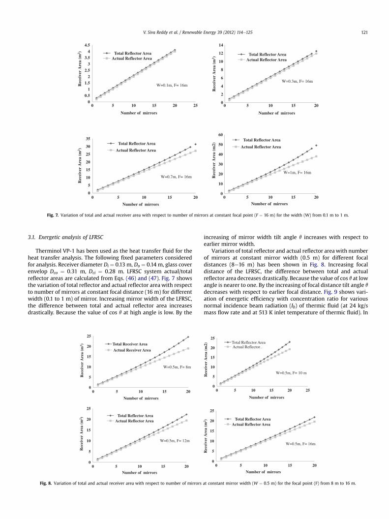
Fig. 7. Variation of total and actual receiver area with respect to number of mirrors at constant focal point (F ¼ 16 m) for the width (W) from 0.1 m to 1 m.
V. Siva Reddy et al. / Renewable Energy 39 (2012) 114e125 121
3.1. Exergetic analysis of LFRSC
Therminol VP-1 has been used as the heat transfer fluid for theheat transfer analysis. The following fixed parameters consideredfor analysis. Receiver diameter Di ¼ 0.13 m, Do ¼ 0.14 m, glass coverenvelop Dco ¼ 0.31 m, Dci ¼ 0.28 m. LFRSC system actual/totalreflector areas are calculated from Eqs. (46) and (47). Fig. 7 showsthe variation of total reflector and actual reflector area with respectto number of mirrors at constant focal distance (16 m) for differentwidth (0.1 to 1 m) of mirror. Increasing mirror width of the LFRSC,the difference between total and actual reflector area increasesdrastically. Because the value of cos q at high angle is low. By the
0
5
10
15
20
25
0 5 10 15 20
Total Receiver Area
Actual Receiver Area
W=0.5m, F= 8m
Number of mirrors
Rec
eive
r A
rea
(m2 )
0
5
10
15
20
25
0 5 10 15 20
Total Reflector AreaActual Reflector Area
Number of mirrors
W=0.5m, F= 12m
Rec
eive
r A
rea
(m2 )
Fig. 8. Variation of total and actual receiver area with respect to number of mirrors
increasing of mirror width tilt angle q increases with respect toearlier mirror width.
Variation of total reflector and actual reflector areawith numberof mirrors at constant mirror width (0.5 m) for different focaldistances (8e16 m) has been shown in Fig. 8. Increasing focaldistance of the LFRSC, the difference between total and actualreflector area decreases drastically. Because the value of cos q at lowangle is nearer to one. By the increasing of focal distance tilt angle q
decreases with respect to earlier focal distance. Fig. 9 shows vari-ation of energetic efficiency with concentration ratio for variousnormal incidence beam radiation (Ib) of thermic fluid (at 24 kg/smass flow rate and at 513 K inlet temperature of thermic fluid). In
0
5
10
15
20
25
0 5 10 15 20 25
Total Reflector AreaActual Reflector …
W=0.5m, F= 10 m
Number of mirrors
Rec
eive
r A
rea
(m2)
0
5
10
15
20
25
0 5 10 15 20
Total Reflector AreaActual Reflector Area
W=0.5m, F= 16m
Rec
eive
r A
rea
(m2 )
Number of mirrors
at constant mirror width (W ¼ 0.5 m) for the focal point (F) from 8 m to 16 m.

63
64
65
66
67
68
69
30 35 40 45 50 55
Ib=400W/m2 Ib=600 W/m2
Ib=800W/m2 Ib=1000W/m2
Ene
rget
ic e
ffic
ienc
y (
I)
Concentration ratio (C)
Ti=513K, m=24kg/s
Fig. 9. Variation of energetic efficiency with concentration ratio for various normalincidence beam radiation (Ib).
Exe
rget
ic e
ffic
ienc
y (
II)
30
31
32
33
34
35
36
37
38
39
40
30 3
IIII
5
b=400W/b=600W/b=800W/b=1000W/
Con
40
m2m2m2m2
centration
45
ratio (C)
Ti=513K, m=24kg
50
/s
55
Fig. 10. Variation of exergetic efficiency with concentration ratio for various normalincidence beam radiation (Ib).
30
31
32
33
34
35
36
37
38
30 35 40 45 50 55
m=12kg/s m=24kg/s
m=36kg/s m=48kg/s
Exe
rget
ic e
ffic
ienc
y (
II)
Concentration ratio (C)
Ti=533K, Ib=400W/m2
Fig. 12. Variation of exergetic efficiency with concentration ratio for various normalincidence beam radiation (Ib).
40
41
42
43
44
45
46
47
48
49
30 35 40 45 50 55
Ti=473K Ti=493K
Ti=513K Ti=533K
Concentration ratio (C)
Pre
ssur
e dr
op (
pa/m
)
m=12kg/s, Ib=400W/m2
Fig. 13. Variation of pressure drop with concentration ratio for various inlet temper-atures (Ti) of thermic fluid.
V. Siva Reddy et al. / Renewable Energy 39 (2012) 114e125122
all incidences beam radiation energetic efficiency slightly increaseswith respect to concentration ratio at constant mass flow rate. Bythe increasing of normal incidence of beam radiation (Ib), energeticefficiency increases with incidence beam radiation (Ib).
Variation of exergetic efficiency with concentration ratio forvarious normal incidence beam radiation (Ib) for mass flow rate ofthermic fluid at 24 kg/s and inlet temperature of 513 K thermic fluidhas been shown in Fig. 10. In all incidences of beam radiation exer-getic efficiency increases linearly with respect to concentration ratioat constant mass flow rate. By the increasing of normal incidence
62.5
63
63.5
64
64.5
65
65.5
66
66.5
30 35 40 45 50 55
m=12kg/s m=24kg/s
m=36kg/s m=48kg/s
Ene
rget
ic e
ffic
ienc
y (
I)
Concentration ratio (C)
Ti=533K, Ib=400W/m2
Fig. 11. Variation of energetic efficiency with concentration ratio for various mass flowrate (m) of thermic fluid.
beam radiation (Ib), exergetic efficiency increases with incidentbeam radiation (Ib). Fig. 11 shows variation of energetic efficiencywith concentration ratio for various thermic fluid mass flow rates atan inlet temperatures of 513 K and normal incidence beam radiationof 400 W/m2. In all mass flow rates of thermic fluid energetic effi-ciency is increasing with respect to concentration ratio at constantinlet temperatures. By increasing of mass flow rate of thermic fluid,energetic efficiency increases with mass flow rate of thermic fluid.
Variation of exergetic efficiency with concentration ratio forvarious thermic fluid mass flow rates at inlet temperatures of 513 Kand normal incidence beam radiation of 400W/m2 has been shownin Fig. 12. In all mass flow rates of thermic fluid, exergetic efficiencyis increasing with respect to concentration ratio at constant inlet
0
100
200
300
400
500
600
700
30 35 40 45 50 55
12kg/s 24kg/s
36kg/s 48kg/s
Ti=473K, Ib=400W/m2
Concentration ratio (C)
Pre
ssur
e dr
op (
pa/m
)
Fig. 14. Variation of pressure drop with concentration ratio for various mass flow rate(m) of thermic fluid.
Air
Fuel
1
16
Deaerator
G
CC
HP-Drum
LP-Drum1
CEP1
HFP
LFP1
HRSG
23
4
5
9
7
8
10
11
15
Condenser
13
12
14
Hp-Supp
Hp-Evap
Hp-Econ
Hp-Econ
CPH
Lp-Econ
Lp-Evap
Lp-Supp
Feed water heater
bc
d
LP-Drum2
6
200 TR
Lp-Econ
Lp-Evap
Lp-Supp
LFP2c
CP
CP
Low pressure Steam Generator
LFRSCLFRSC
HPT LPT LPT
C TG
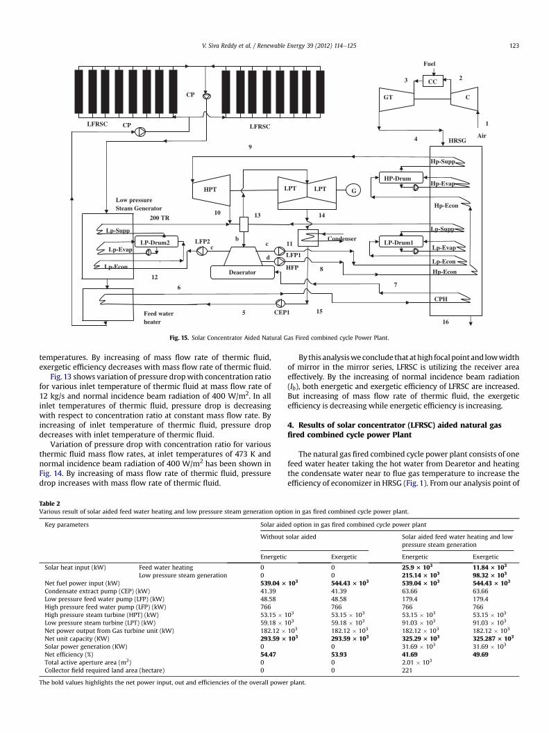
Fig. 15. Solar Concentrator Aided Natural Gas Fired combined cycle Power Plant.
V. Siva Reddy et al. / Renewable Energy 39 (2012) 114e125 123
temperatures. By increasing of mass flow rate of thermic fluid,exergetic efficiency decreases with mass flow rate of thermic fluid.
Fig.13 shows variation of pressure dropwith concentration ratiofor various inlet temperature of thermic fluid at mass flow rate of12 kg/s and normal incidence beam radiation of 400 W/m2. In allinlet temperatures of thermic fluid, pressure drop is decreasingwith respect to concentration ratio at constant mass flow rate. Byincreasing of inlet temperature of thermic fluid, pressure dropdecreases with inlet temperature of thermic fluid.
Variation of pressure drop with concentration ratio for variousthermic fluid mass flow rates, at inlet temperatures of 473 K andnormal incidence beam radiation of 400 W/m2 has been shown inFig. 14. By increasing of mass flow rate of thermic fluid, pressuredrop increases with mass flow rate of thermic fluid.
Table 2Various result of solar aided feed water heating and low pressure steam generation opti
Key parameters Solar aide
Without
Energetic
Solar heat input (kW) Feed water heating 0Low pressure steam generation 0
Net fuel power input (kW) 539.04 3
Condensate extract pump (CEP) (kW) 41.39Low pressure feed water pump (LFP) (kW) 48.58High pressure feed water pump (LFP) (kW) 766High pressure steam turbine (HPT) (kW) 53.15 � 1Low pressure steam turbine (LPT) (kW) 59.18 � 1Net power output from Gas turbine unit (kW) 182.12 �Net unit capacity (KW) 293.59 3
Solar power generation (KW) 0Net efficiency (%) 54.47Total active aperture area (m2) 0Collector field required land area (hectare) 0
The bold values highlights the net power input, out and efficiencies of the overall powe
Bythis analysisweconclude that athigh focalpointand lowwidthof mirror in the mirror series, LFRSC is utilizing the receiver areaeffectively. By the increasing of normal incidence beam radiation(Ib), both energetic and exergetic efficiency of LFRSC are increased.But increasing of mass flow rate of thermic fluid, the exergeticefficiency is decreasing while energetic efficiency is increasing.
4. Results of solar concentrator (LFRSC) aided natural gasfired combined cycle power Plant
The natural gas fired combined cycle power plant consists of onefeed water heater taking the hot water from Dearetor and heatingthe condensate water near to flue gas temperature to increase theefficiency of economizer in HRSG (Fig. 1). From our analysis point of
on in gas fired combined cycle power plant.
d option in gas fired combined cycle power plant
solar aided Solar aided feed water heating and lowpressure steam generation
Exergetic Energetic Exergetic
0 25.9 3 103 11.84 3 103
0 215.14 3 103 98.32 3 103
103 544.43 3 103 539.04 3 103 544.43 3 103
41.39 63.66 63.6648.58 179.4 179.4766 766 766
03 53.15 � 103 53.15 � 103 53.15 � 103
03 59.18 � 103 91.03 � 103 91.03 � 103
103 182.12 � 103 182.12 � 103 182.12 � 103
103 293.59 3 103 325.29 3 103 325.287 3 103
0 31.69 � 103 31.69 � 103
53.93 41.69 49.690 2.01 � 103
0 221
r plant.
Constituent Molefraction
Molecularweight
Massfraction
Exergy(KJ/Kmol)
Exergy(KJ/Kg)
Methane (CH4) 0.8451 16.043 0.7017 706859 36566Ethane (C2H6) 0.077 30.070 0.1198 115748 5989Propane (C3H8) 0.0245 44.097 0.05592 52957 2741Butane (C4H10) 0.0013 58.123 0.00039 3664 18.91Carbon dioxide (CO2) 0.052 44.027 0.1185 1049 54.12Nitrogen (N2) 0.0001 28.056 0.0001452 0.07225 0.007437CNG 1 19.32 1 880276 45369
Net calorific value of compressed natural gas (NCV) ¼ 44920 KJ/Kg.Exergy of compressed natural gas (NCV) ¼ 45369 KJ/Kg.Entropy of the flue gas and Gibbs function values are obtained using Table A-18 toTable A-20 and TableA-26E to Table A-27 from Cengel and Boles [17].
V. Siva Reddy et al. / Renewable Energy 39 (2012) 114e125124
view the solar feed water preheating process in existing powerplant can be accomplished by feed water heaters replaced by solaraided option and mass flow rate of excess water available in thedearetor is used to produce low pressure steam. The layout isshown in Fig. 15. The excess low pressure steam will expand in therespective low pressure turbine and finally will be exhausted to thecondenser. The following fixed parameters are considered foranalysis. Width and length of the LFRSC glass is 0.5 m & 500 m andfocal distance is 14 m, total number of reflectors in single LFRSC is40. Receiver diameter Di ¼ 0.13 m, Do ¼ 0.14 m, glass cover envelopDco ¼ 0.31 m, Dci ¼ 0.28 m, concentration ratio is 48, inlettemperature is 260 �C, average mass flow rate (mf) is 22.06 kg/s,Ta¼303 K, Ti¼533 K, To ¼ 584, Ts ¼ 5800 K, Pr ¼ 5, Kf ¼ 0.0989 W/m.K, Kr ¼ 37 W/m.K, Cp ¼ 2.28 kJ/kg.K, Therminol VP-1 as the heattransfer fluid. Assumptions made to design the solar thermal aidednatural gas fired combined cycle power plant were: Average solarbeam radiation of 400 W/m2 in available 8 h/day. Remaining 16 hbackup from solar thermal storage facility. Feed water heater effi-cacy 95% and low pressure steam generator efficiency 90%. Heatloss was calculated by the using equation (48e51) for a Tr ¼ 573 K,solar heat available and use full gain of heat for single LFRSC sectionhas been calculated by using equations (60e69) as follows.Ul ¼ 3.413 W/m2, QI ¼ 3.92 � 103 kW, Qu ¼ 2.57 � 103 kW,ExI ¼ 3.65 � 103 kW, EXu ¼ 1.24 � 103 kW.
The results indicates that, both energetic and exergetic efficiencyof solar aided feedwater heating and low pressure steam generationin combined cycle power plant is less than the conventionalcombined cycle power plant efficiency. But exergetic efficiency iscomparatively higher than the energetic efficiency. Table 2 showsa summary of the results. Solar aided feed water heating and lowpressure steam generation in combine cycle power plant requiressolar thermal power input of 241.04 � 103 kW by that input it canproduce electrical power of 31.70 � 103 kWwith a total power plantenergetic and exergetic efficiency of 41.68% and 49.69% respectively.The land area required for daily solar thermal power input is around221 ha. But natural gas fired combined cycle power plant exergeticand energetic efficiency is respectively 53.93%e54.47%. The solarthermal aidedpowerplanthas lowefficiencybecause of the low inletsteam temperature and pressures (479.68 K, 5.6 bar).
5. Conclusion
The energetic and exergetic analysis has been carried out fornatural gas fired combined cycle power plant, Linear FresnelReflecting Solar Concentrator and also solar aided natural gas firedcombined cycle power plant. The exergetic analysis shows thatcombustion chamber subsystem followed by heat recovery steamgenerator (HRSG) is main source of exergy loss in a natural gas firedcombined cycle power plant. The exergetic power loss in thecondenser is less. In the analysis linear Fresnel reflecting solarconcentrator (LFRSC) by increasing focal distance and decreasingwidth linear Fresnel reflector, total reflector area come close toactual reflector area. By the increasing of normal incidence beamsolar radiation (Ib) both energetic and exergetic efficienciesincreases. Increasing inlet temperature and decreasing the massflow rate of thermic fluid exergetic efficiency is increased. Byanalysis of solar aided feed water heating and low pressure steamgeneration option in the natural gas fired combined cycle powerplant, an instantaneous increase in power generation capacity ofabout 10% is observed by producing of extra low pressure steam of55.67 kg/s. But both energetic and exergetic efficiencies appearhigh compared to solar alone thermal power plant and lowcompared to natural gas fired combined cycle power plants. The netelectrical generation capacity is increasing from 293.59� 103 kW to325.29 � 103 kW with land area of 221 ha.
Nomenclature
Aa Absorber Area (m2)Ar Receiver Area (m2)C Concentration ratioCp Specific heat of Therminol VP-1 (kJ/kg.K)c Bulk velocity of the working fluid (m2)Do Receiver outside diameter (m)DI Receiver inside diameter (m)Dci Glass cover inside diameter (m)Dco Glass cover outside diameter (m)ExI Exergetic heat input (kW)Exu Exergetic heat gain (kW)g Acceleration due to gravity value (m2/s)h0 Methalpy (kJ/kg)h Enthalpy (kJ/kg)_Idestroyed Irreversibility (kW)Ib Solar beam radiation (W/m2)Kf Thermal conductivity of Therminol VP-1 (W/m.K)Kr Thermal conductivity of Receiver (W/m.K)mf Mass flow rate of Therminol VP-1 (kg/s)QI Input heat (kW)Qu Actual heat gain (kW)Qk Heat transfer to system from source (kJ/s)S Absorbed heat (kW)s Entropy (kJ/kg.K)Ts Sun temperature (K)Ti Therminol VP-1 inlet temperature (K)Te Therminol VP-1 outlet temperature (K)Tr Receiver temperature (K)Ta Atmospheric temperature (K)Tk Source temperature (K)Ul Heat loss coefficient (W/m2.K)W Net work developed by the system(kJ/s)Z Altitude of the stream above the sea level (m)J Exergy associated with mass flow (kJ/kg)
Suffixgen generationder Deaeratori inleto outletgþa Natural gas þ airp combustion products0 dead state
Appendix
Exergy of compressed natural gas:

V. Siva Reddy et al. / Renewable Energy 39 (2012) 114e125 125
References
[1] Indian Renewable Energy Status Report. NREL/TP 6A20-48948 � October 2010,<http://www.nrel.gov/>.
[2] <http://www.powermin.nic.in/JSP_SERVLETS/internal.sjsp>.[3] Srinivas T. Study of a deaerator location in triple-pressure reheat combined
power cycle. Energy 2009;34(9):1364e71.[4] Reddy BV, Mohamed K. Exergy analysis of natural gas fired combined
cycle power generation unit. International Journal of Exergy 2007;4(2):180e96.
[5] Srinivas T, Gupta AVSSKS, Reddy BV. Performance simulation of 210 MWnatural gas fired combined cycle power plant. Journal of energy. Heat andMass Transfer 2007;29(1):61e82.
[6] Khaliq A, Kaushik SC. Second-law based thermodynamic analysis of Brayton /Rankine combined power cycle with reheat. Applied Energy 2004;78(2):179e97.
[7] Negi BS, Kandpal TC, Mathur SS. Designs and performance characteristics ofa linear fresnel reflector solar concentrator with a flat vertical absorber. Solar& Wind Technology 1990;7(4):379e92.
[8] Negi BS, Mathur SS, Kandpal TC. Optical and thermal performance Evaluationof a linear fresnel reflector solar concentrator I. Solar & Wind Technology1989;6(5):589e93.
[9] Singh PL, Sarviya RM, Bhagoria JL. Thermal performance of linear Fresnelreflecting solar concentrator with trapezoidal cavity absorbers. AppliedEnergy 2010;87(2):541e50.
[10] Singh PL, Sarviya RM, Bhagoria JL. Heat loss study of trapezoidal cavityabsorbers for linear solar concentrating collector. Energy Conversion andManagement 2010;51(2):329e37.
[11] Facao J, Oliveira A. Numerical simulation of a trapezoidal cavity receiver fora linear Fresnel solar collector concentrator. RenewableEnergy2011;36(1):90e6.
[12] Gupta MK, Kaushik SC. Exergetic utilization of solar energy for feed waterpreheating in a conventional thermal power plant. International Journal ofEnergy Research 2009;33(6):593e604.
[13] Reddy KS, Suresha MVJJ, Ajit KK. 4-E (Energy, Exergy, Environment, andEconomic) analysis of solar thermal aided coal-fired power Plants. Energy forSustainable Development 2010;14(4):267e79.
[14] Popov D. An option for solar thermal repowering of fossil fuel fired powerplants. Solar Energy; 2010. doi:10.1016/j.solener.2010.11.017.
[15] Seyedan B, Dhar PL, Gaur RR, Bindra GS. Optimization of Waste heat recoveryboiler of a combined cycle power plant. Journal of Engineering for GasTurbines and Power 1996;118:561e4.
[16] Klein SA, Alvarado F. Engineering Equation Solver, Version 8.629. Middleton,WI: F Chart Software; 2010.
[17] Cengel YA, Michael A. Thermodynamics an Engineering Approach. New Delhi:Tata McGraw Hill; 2006.
[18] Negi BS, Mathur SS, Kandpal TC. Optical design and concentration charac-teristics of linear fresnel reflector Solar concentrators-II mirror elements ofequal width. Energy Conversion and Management 1991;31(3):221e32.
[19] Singh PL, Ganesan S, Yadava GC. Performance of a linear Fresnel concentratingsolar device. Renew Energy 1999;18(3):409e16.
[20] Petela R. Exergy of heat radiation. Transactions of ASME. Journal of HeatTransfer 1964;86(2):187e92.
[21] Odeh SD, Morrison GL, Behnia M. Modeling of parabolic trough direct steamgeneration solar collectors. Solar Energy 1998;62(6):395e406.
[22] Duffie JA, Beckman WA. Solar Engineering of Thermal Processes. New York:Wiley; 1991.