Embed Size (px)
Citation preview
Canadian Journal of Basic and Applied Sciences
©PEARL publication, 2015
CJBAS Vol. 03(10), 273-282, October 2015
ISSN 2292-3381
Exergy Based Analysis of an Open Cycle Gas Turbine Power Plant
Mukesh Gupta , Raj Kumar
Department of Mechanical Engineering, YMCA University of Science & Technology Faridabad, Haryana, India-121006
Keywords: Abstract
Exergetic analysis,
Open cycle gas turbine,
Exergy destruction
Open cycle gas turbine power plants play a significant role in the power generation
industry. In India alone, 10.5% of the total thermal power capacity is generated by gas
turbine power plants. Hence, analysis of these power plants is of significant interest
from thermodynamic point of view. Over the years, many researchers have analysed
the performance of open cycle gas turbine power plants using the approach based on
first law of thermodynamics which uses energy as the criterion for defining the
performance of the power plants. However use of this approach has its limitations as it
is unable to take into account the irreversibilities which are inherent part of the system.
To take into account these irreversibilities, a new approach was developed based on the
second law of thermodynamics. In this approach, exergy is the criterion for defining the
performance of a thermal system. This approach allows us to take into consideration
the irreversibilities associated with the various components of the system. In the current
study, an exergy based approach has been illustrated for an open cycle gas turbine
power plant. For formulation, a 25 MW open cycle gas turbine power plant has been
considered as an example. Detailed exergy analysis has been done for the variou s plant
components. Exergy destruction has been calculated for various components and the
effect of thermodynamic variables on the exergy destruction in various components has
been analyzed. Finally, equations have been developed which provide a correlatio n
between the exergy destruction in different components as a function of the
thermodynamic variables under consideration. The current study provides a robust
method which can be used to analyze open cycle gas turbines of different capacities.
1. Introduction
Open cycle gas turbine power plants play a significant role in the power generation industry. In
India alone, 10.5% of the total thermal power capacity is generated by gas turbine power plants.
Corresponding Author :
E-mail, [email protected] – Tel, (+91) 9999766752
Mukesh Gupta et al. - Can. J. Basic Appl. Sci. Vol. 03(10), 273-282, October 2015
274
Many researchers have put forward different approaches to analyze the performance of gas turbine
power plants. Most of these approaches are based on the first law of thermodynamics. However,
there is a major drawback with these approaches. In the first law of thermodynamics, energy is the
criterion based on which the performance of a thermal system is defined. However, energy based
approach fails to consider the effects of irreversibilities which are inherent with any thermal system.
Hence, for better understanding of the performance of a thermal system, a new approach based on
the second law of thermodynamics was proposed. In this approach, exergy is the criterion for
analyzing the performance of a thermal system.
Exergy analysis and its applications in calculating entropy generation has been described [1].
Exergy based methods have been used for optimization of a single and double effect vapor
absorption refrigeration system [2, 3, 4]. An elaborate method to analyze the operation of a plant
using various exergetic variables such as exergetic efficiency, the rates of exergy destruction,
exergy destruction ratio has been provided [5]. Different researchers have used thermodynamic
relations between the energy and exergy losses to analyze the performance of a modern coal fired
electrical generation station [6, 7, 8, 9, 10]. Various efficiencies of fossil-fuel power plants have
been studied in detail using the exergy concepts [11]. Comparison between conventional and
fluidized bed power plant have been made and improving techniques have also been given using
exergy based methods for the conventional plants [12] Graphical exergy analysis has been used to
locate inefficient segments in the combined cycle plant [13]. Exergy based analysis has been used
for performance analysis of different processes such as production of hydrogen and hydrogen-
derived fuels, electrical and thermal power generation, thermal energy storage [14, 15, 16]. To
evaluate the exergy losses in the individual components of a cogeneration system, exergy analysis
for each component in the subsystems has been done [17]. Estimation of avoidable and unavoidable
exergy destruction and investment costs associated with different thermal components has been
done [18]. The primary way of keeping the exergy destruction, in a combustion process, within a
reasonable limit is to reduce the irreversibility in heat conduction [19].
2. Methodology
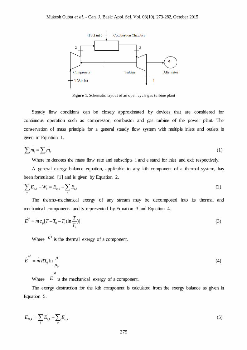
A typical open cycle gas turbine power plant is shown in Figure 1.
Mukesh Gupta et al. - Can. J. Basic Appl. Sci. Vol. 03(10), 273-282, October 2015
275
Figure 1. Schematic layout of an open cycle gas turbine plant
Steady flow conditions can be closely approximated by devices that are considered for
continuous operation such as compressor, combustor and gas turbine of the power plant. The
conservation of mass principle for a general steady flow system with multiple inlets and outlets is
given in Equation 1.
. .
i em m (1)
Where m denotes the mass flow rate and subscripts i and e stand for inlet and exit respectively.
A general exergy balance equation, applicable to any kth component of a thermal system, has
been formulated [1] and is given by Equation 2.
, , ,e k k q k i k
e i
E W E E (2)
The thermo-mechanical exergy of any stream may be decomposed into its thermal and
mechanical components and is represented by Equation 3 and Equation 4.
. .
0 0
0
[ (ln )]T
p
TE mc T T T
T (3)
Where
.TE is the thermal exergy of a component.
. .
0
0
lnM
pE m RT
p (4)
Where . M
E is the mechanical exergy of a component.
The exergy destruction for the kth component is calculated from the exergy balance as given in
Equation 5.
. . .
, , ,D k i k e k
i e
E E E (5)
Mukesh Gupta et al. - Can. J. Basic Appl. Sci. Vol. 03(10), 273-282, October 2015
276
2.1. Illustrative Example
For analysis purpose, an open cycle gas turbine power plant of 25 MW capacity has been
considered. The system comprises of an air compressor, a combustion chamber and a gas turbine.
The mass flow rate of air is 212.95 kg/ s and air enters the compressor at a temperature of 200 C
and a pressure of 0.981 bars. The pressure increases to 4.81 bars through the compressor whose
isentropic efficiency has been taken as 80%. The inlet temperature to the gas turbine is 11230C and
a pressure of 1.01325 bars. The isentropic efficiency of the turbine has been taken as 80%. The
exhaust gases from the turbine are at 8170C and 1.10 bars. The fuel (natural gas) is injected at 200C
and 22 bars.
3. Results and Discussion
3.1. Exergy calculations for plant
The net flow rates for different streams entering and leaving the system are shown in Table 1.
Positive values indicate the exergy flow rates of the products and the negative values represent the
exergy flow rates of resources or fuel for a particular component.
Table 1. Property values and thermal, mechanical, chemical and net exergy flow rates at various state points in the
gas turbine power plant
State .
m (kg/s) P (bar) T (K)
.TE (MW)
. M
E (MW)
.CE (MW)
.
E (MW)
1 212.95 0.981 293.00 0.00 0.00 0.00 0.00
2 212.95 4.2 481.60 10.52 26.146 0.00 36.916
3 216.66 1.01325 1123.00 108.768 23.89 0.7488 133.406
4 216.66 1.1 817.60 55.80 1.5 0.7488 58.04
5 3.71 22 293.00 0.00 0.8240 190.53 191.39
Where .CE represents the chemical exergy [1] and
.
E represents the net exergy flow for a
stream.
Exergy balance values for each component are given in Table 2.
Table 2. Exergy balance for each component in the gas turbine power plant
Component .WE (MW)
.CE (MW)
.TE (MW)
. M
E (MW)
.DE
Compressor -40.363 0.00 10.52 26.146 3.697
Combustion chamber 0.00 -189.78 98.248 -3.083 94.615
Gas Turbine 66.498 0.00 -52.698 -22.39 8.59
Overall Plant 26.135 -189.78 56.07 0.673 106.902
Mukesh Gupta et al. - Can. J. Basic Appl. Sci. Vol. 03(10), 273-282, October 2015
277
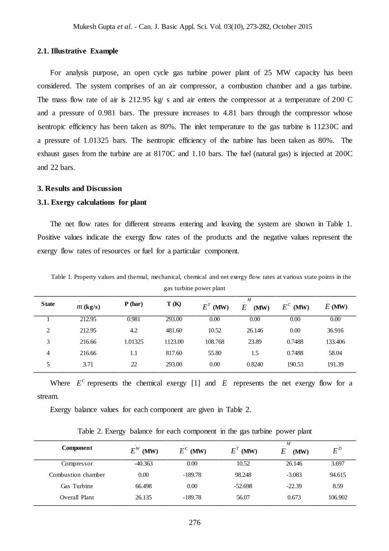
The values of exergy destruction calculated in Table 2 are plotted in Fig. 2.
Figure 2. Exergy Destruction in various components and plant
From Figure 2, it can be seen that maximum exergy destruction takes place in the combustion
chamber followed by the gas turbine and the air compressor. Hence the combustion chamber is least
efficient from the exergetic view point.
3.2 Effect of thermodynamic variables on plant performance
The next step in the analysis is to study the effect of thermodynamic variables on the
performance of the gas turbine power plant. For this the following two thermodynamic variables
have been considered:
1. Compressor pressure ratio
2. Air inlet temperature
The effects of these two thermodynamic variables have been analyzed with respect to the
exergy destruction values for various components.
3.2.1. Effect of compressor pressure ratio (rp)
The effect of variation of the compressor pressure ratio on exergy destruction in compressor,
combustion chamber and gas turbine are shown in Fig. 3, Fig. 4 and Fig. 5 respectively.
Mukesh Gupta et al. - Can. J. Basic Appl. Sci. Vol. 03(10), 273-282, October 2015
278
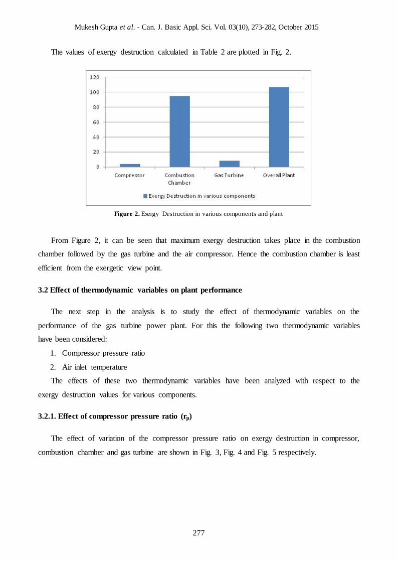
Figure 3. Exergy destruction in compressor Vs. Compressor pressure ratio
Figure 4. Exergy destruction in combustion chamber Vs. Compressor pressure ratio
Figure 5. Exergy destruction in Gas turbine Vs. Compressor pressure ratio
From Fig. 3, 4 and 5 it is clear that the exergy destruction increases for all the three components
of the plant with increase in compressor pressure ratio. The effect of increase in compressor
pressure ratio is felt most in the gas turbine. For the given range of compressor pressure ratios, the
increase in exergy destruction ratio is terms of percentage are given in Table 3.
Table 3. Maximum exergy destruction variation in various components
Mukesh Gupta et al. - Can. J. Basic Appl. Sci. Vol. 03(10), 273-282, October 2015
279
Component Maximum exergy destruction variation (% )
Compressor 70.002
Combustion chamber 90.03
Gas turbine 230.39
Based on the analysis done, following equations have been developed which express the exergy
destruction in compressor, combustion chamber and gas turbine as a function of compressor
pressure ratio. These equations have been checked for different ranges of compressor pressure ratio
and the results have been fairly satisfactory. These are represented as Equations (6), (7) and (8).
(6) .
= 15.5271 + 49.8326ln(r )D
CC pE (7)
.
= -22.1874 + 88.9799ln(r ) D
GT pE (8)
Where. D
CompE , . D
CCE ,. D
GTE represent the exergy destruction in compressor, combustion chamber and
gas turbine.
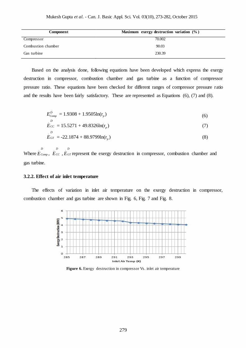
3.2.2. Effect of air inlet temperature
The effects of variation in inlet air temperature on the exergy destruction in compressor,
combustion chamber and gas turbine are shown in Fig. 6, Fig. 7 and Fig. 8.
Figure 6. Exergy destruction in compressor Vs. inlet air temperature
.
= 1.9308 + 1.9505ln(r ) D
Comp pE
Mukesh Gupta et al. - Can. J. Basic Appl. Sci. Vol. 03(10), 273-282, October 2015
280
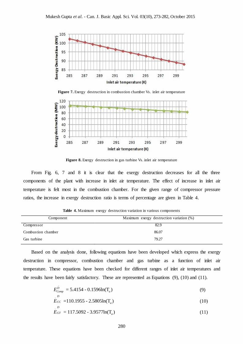
Figure 7. Exergy destruction in combustion chamber Vs. inlet air temperature
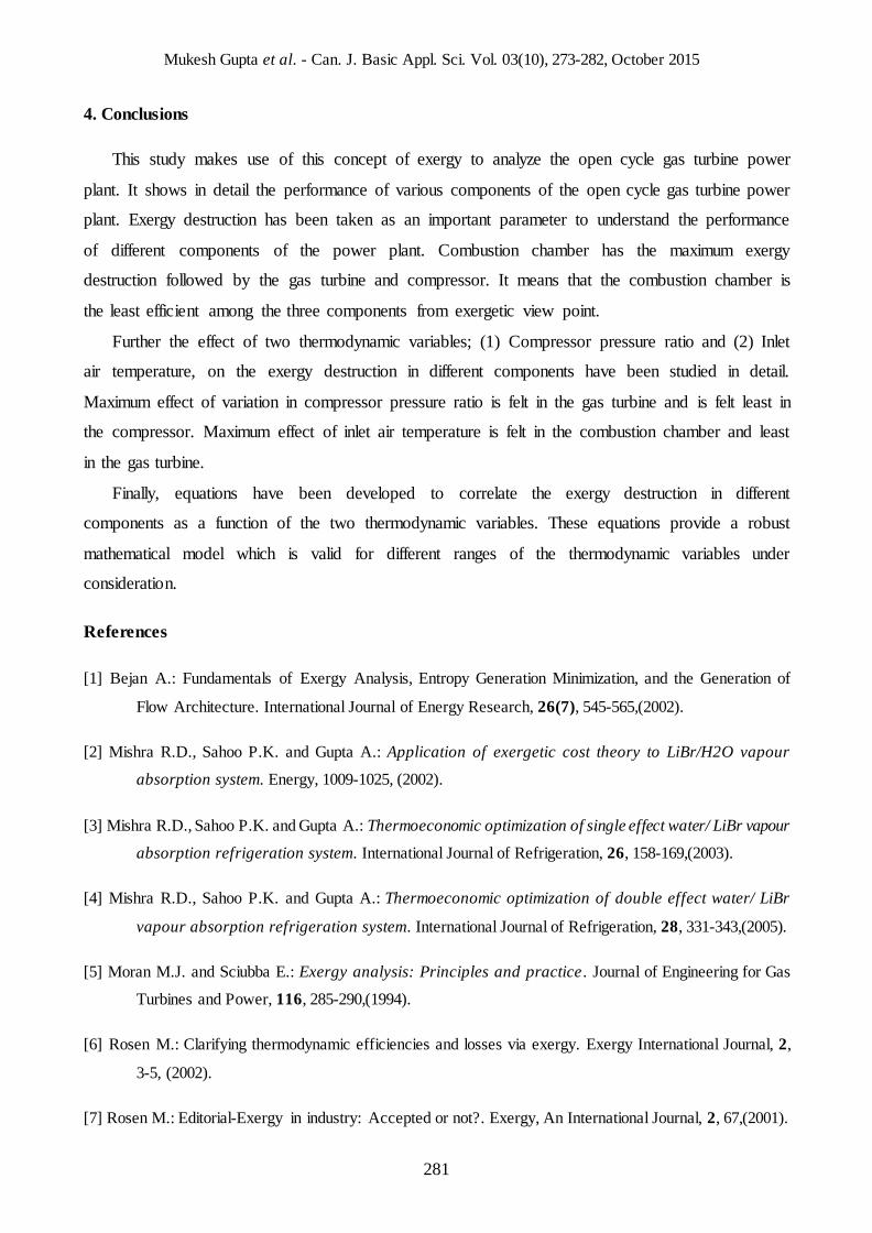
Figure 8. Exergy destruction in gas turbine Vs. inlet air temperature
From Fig. 6, 7 and 8 it is clear that the exergy destruction decreases for all the three
components of the plant with increase in inlet air temperature. The effect of increase in inlet air
temperature is felt most in the combustion chamber. For the given range of compressor pressure
ratios, the increase in exergy destruction ratio is terms of percentage are given in Table 4.
Table 4. Maximum exergy destruction variation in various components
Component Maximum exergy destruction variation (%)
Compressor 82.9
Combustion chamber 86.07
Gas turbine 79.27
Based on the analysis done, following equations have been developed which express the exergy
destruction in compressor, combustion chamber and gas turbine as a function of inlet air
temperature. These equations have been checked for different ranges of inlet air temperatures and
the results have been fairly satisfactory. These are represented as Equations (9), (10) and (11).
.
= 5.4154 - 0.1596ln(T ) D
Comp aE (9)
.
=110.1955 - 2.5805ln(T ) D
CC aE (10)
.
= 117.5092 - 3.9577ln(T ) D
GT aE (11)
Mukesh Gupta et al. - Can. J. Basic Appl. Sci. Vol. 03(10), 273-282, October 2015
281
4. Conclusions
This study makes use of this concept of exergy to analyze the open cycle gas turbine power
plant. It shows in detail the performance of various components of the open cycle gas turbine power
plant. Exergy destruction has been taken as an important parameter to understand the performance
of different components of the power plant. Combustion chamber has the maximum exergy
destruction followed by the gas turbine and compressor. It means that the combustion chamber is
the least efficient among the three components from exergetic view point.
Further the effect of two thermodynamic variables; (1) Compressor pressure ratio and (2) Inlet
air temperature, on the exergy destruction in different components have been studied in detail.
Maximum effect of variation in compressor pressure ratio is felt in the gas turbine and is felt least in
the compressor. Maximum effect of inlet air temperature is felt in the combustion chamber and least
in the gas turbine.
Finally, equations have been developed to correlate the exergy destruction in different
components as a function of the two thermodynamic variables. These equations provide a robust
mathematical model which is valid for different ranges of the thermodynamic variables under
consideration.
References
[1] Bejan A.: Fundamentals of Exergy Analysis, Entropy Generation Minimization, and the Generation of
Flow Architecture. International Journal of Energy Research, 26(7), 545-565,(2002).
[2] Mishra R.D., Sahoo P.K. and Gupta A.: Application of exergetic cost theory to LiBr/H2O vapour
absorption system. Energy, 1009-1025, (2002).
[3] Mishra R.D., Sahoo P.K. and Gupta A.: Thermoeconomic optimization of single effect water/ LiBr vapour
absorption refrigeration system. International Journal of Refrigeration, 26, 158-169,(2003).
[4] Mishra R.D., Sahoo P.K. and Gupta A.: Thermoeconomic optimization of double effect water/ LiBr
vapour absorption refrigeration system. International Journal of Refrigeration, 28, 331-343,(2005).
[5] Moran M.J. and Sciubba E.: Exergy analysis: Principles and practice. Journal of Engineering for Gas
Turbines and Power, 116, 285-290,(1994).
[6] Rosen M.: Clarifying thermodynamic efficiencies and losses via exergy. Exergy International Journal, 2,
3-5, (2002).
[7] Rosen M.: Editorial-Exergy in industry: Accepted or not?. Exergy, An International Journal, 2, 67,(2001).
Mukesh Gupta et al. - Can. J. Basic Appl. Sci. Vol. 03(10), 273-282, October 2015
282
[8] Rosen M.: Energy and Exergy based comparison of coal fired and nuclear steam power plants. Exergy
International Journal, 3, 180-192,(2001).
[9] Rosen M.: Energy crisis or exergy crisis?. Exergy, An International Journal, 2, 125-127, (2002).
[10] Rosen M., Dincer I.: Thermoeconomic Analysis of power plants: an application to a coal fired electrical
generating station. Energy Conversion and Management, 44, 2743-2761,(2003).
[11] Horlock J.H., Young J.B., Manfrida G.: Exergy Analysis of Modern Fossil– Fuel Power Plant. Journal
of Engineering for Gas Turbines and Power, 122, 1–7, (2000).
[12] Oktay Z.: Investigation of coal-fired power plants in Turkey and a case study. Applied Thermal Energy,
29, 550-557, (2009).
[13] Jin H., Ishida M. , Kobayashi M., Nunokawa M.: Exergy Evaluation of Two Current Advanced Power
Plants: Supercritical Steam Turbine and Combined Cycle. Tranactions of ASME, 199, 250–256,
(1997).
[14] Rosen M.A.: Second-Law Analysis: Approaches and Implications. International Journal of Energy
Research, 23, 415–429,(1999).
[15] Rosen M.A.: Assessing Energy Technologies and Environmental Impacts with the Principles of
Thermodynamics. Applied Energy, 72, 427–441,(2002).
[16] Rosen M.A., Exergy Methods for Assessing and Comparing Thermal Storage Systems. International
Journal of Energy Research, 27(4), 415–430, (2003).
[17] Ganapathy T., Alagumurthi N., Gakkhar R. P., Murugesan K.: Exergy Analysis of Operating Lignite
Fired Thermal Power Plant. Journal of Engineering Science and Technology Review 2 (1), 123-130,
(2009).
[18] Tsatsaronis G., Park M.: On Avoidable and Unavoidable Exergy Destructions and Investment Costs in
Thermal Systems. Energy Conversion & Management, 43(9), 1259-1270, (2002).
[19] Som S.K., Datta A.: Thermodynamic irreversibilities and exergy balance in combustion processes.
Progress in Energy and Combustion Science 34, 351–376, (2008).


![Exergy Analysis of Vapor Compression Cycle...compression cycle, with flash intercooling with R22 using the exergy method and gave some useful conclusions. Dincer [17] asserts that](https://img.pdfslide.net/doc/110x75/5f36330828f5ef049b4d3cef/exergy-analysis-of-vapor-compression-cycle-compression-cycle-with-flash-intercooling.jpg)
![Exergy analysis of the Szewalski cycle with a waste …...eters of the Szewalski binary vapour cycle was performed by Kowalczyk et al.[3], who presented the energy and exergy analysis](https://img.pdfslide.net/doc/110x75/5f36873b62461f4a731f3996/exergy-analysis-of-the-szewalski-cycle-with-a-waste-eters-of-the-szewalski-binary.jpg)