Embed Size (px)
Citation preview
277 Technology Parkway • Auburn, AL 36830
NCAT Report 93-04
EXPERIENCE WITH STONEMATRIX ASPHALT IN THEUNITED STATES
By
Dr. E.R. Brown
March 1992
EXPERIENCE WITH STONE MATRIX ASPHALT IN THE UNITED STATES
By
E.R. BrownDirector
National Center for Asphalt TechnologyAuburn University, Alabama
Sponsored by National Asphalt Pavement AssociationNAPA Building
5100 Forbes Blvd.Lanham, MD 20706-4413
NCAT Report 93-04
March 1992
i
DISCLAIMER
The contents of this report reflect the views of the authors who are solely responsible forthe facts and the accuracy of the data presented herein. The contents do not necessarily reflectthe official views and policies of the National Center for Asphalt Technology of AuburnUniversity or the National Asphalt Pavement Association. This report does not constitute astandard, specification, or regulation.
ACKNOWLEDGMENTS
The National Center for Asphalt Technology (NCAT) thanks the National AsphaltPavement Association for sponsoring this work. NCAT also thanks the states for providing thedata needed to describe the various projects and for reviewing the report. In particular, NCATthanks Mr. Ron Collins, Georgia DOT; Mr. Ron Walker, Indiana DOT; Mr. Dan Vriebel,Michigan DOT; Mr. Pat McDaniel, Missouri; and Mr. Lynn Larson, Wisconsin DOT.
Brown
1
EXPERIENCE WITH STONE MATRIX ASPHALT IN THE UNITED STATES
E.R. Brown
INTRODUCTION
Stone Matrix Asphalt (SMA), which has been used in Europe for approximately 20 years, wasfirst developed to provide resistance to abrasion by studded tires. In the 1970s, studded tireswere banned in Germany, and the use of SMA mixtures declined because of the higher materialand construction costs and there no longer appeared to be a critical need for these mixtures.Rutting of Hot Mix Asphalt (HMA) became a bigger problem in Germany in the 1980s due toincreased tire pressure, wheel loads, and traffic volume, and SMA mixtures began to be usedagain. Studded tires have continued to be used in Sweden, and SMA mixtures have continued toprovide good performance under these severe loading conditions. Other European countries haveused SMA mixtures with similar success to that observed in Germany and Sweden.
A study group from the U.S. consisting of contractors, National Asphalt Pavement Association,Asphalt Institute, Federal Highway Administration (FHWA), and State Highway agencies visitedEurope in the fall of 1990 to observe the quality of roads in Europe and to discuss constructionprocedures as well as contracting procedures. One of the items with which this group was mostimpressed was the performance of SMA mixtures. Based on this trip and the observedperformance of SMA mixtures, it was decided shortly after this trip to construct a SMA testsection in the US sometime in 1991.
In January 1991 plans were made by the FHWA to help support the construction of a SMA testsection in Michigan. This state was selected because the climate was similar to that in Europeand there was much interest in SMA within the state DOT and industry.
DESCRIPTION
SMA mixtures consist of a large coarse aggregate content, fine aggregate, high filler content,asphalt cement with or without a modifier and usually a cellulose or mineral fiber. Thesemixtures contain a large coarse aggregate content (approximately 70 percent) and enough fineaggregate to help fill the voids in the coarse aggregate. The strength of this mix is gained fromstone on stone contact. This mix is designed to have 3-4 percent air voids, and it has a relativelyhigh asphalt content due to the high amount of voids in the mineral aggregate. The mix containsa high filler content (approximately 10 percent passing the No. 200 sieve), and it typicallycontains a polymer in the asphalt cement or fiber (cellulose or mineral) in the mixture to preventdrainage of the asphalt cement. This mixture has a surface appearance similar to that of an opengraded friction course, however it has low in-place air voids similar to that of a dense gradedHMA.
The high asphalt content produces a mixture that is easily compacted and that should be durable.If the asphalt content is excessive it will tend to push the aggregate apart and prevent stone onstone contact. An asphalt content that produces 3-4 percent air voids in laboratory compactedsamples is desirable.
Brown
2
OBJECTIVE
The objective of this report is to discuss the construction of five SMA sections placed in the U.S.in 1991 and to summarize what was learned from these projects.
SCOPE
Major SMA projects were constructed in the U.S. in 1991 in the following five states: Georgia,Indiana, Michigan, Missouri, and Wisconsin. Other projects were constructed at variouslocations, but these were the major projects. There were many variations between these projectsthat should provide a wide base of experience that should be helpful in identifying potentialproblems and providing solutions to these problems. These projects have been evaluated afterbeing opened to traffic to determine if any premature distresses had occurred. Each of these 5projects is discussed below in the order that construction occurred.
Wisconsin SMA Construction
The Wisconsin SMA section was constructed on July 10, 1991 in the west bound lane of I-94located approximately 8 miles west of Waukesha. The SMA at this section was placed 1½ inchesthick and contained a polymer called Vestoplast. A copy of the special provisions for this projectis provided in Appendix A.
The mix design and construction control data are shown in Table 1. The mix design which wasprepared by the Wisconsin DOT was performed using 50-blow Marshall compactive effort andindicated that the optimum asphalt content was 5.7 percent. The hammer used for thiscompaction had a slanted foot and rotating base. This hammer has been shown to produce ahigher density than the mechanical hammer with fixed base which may partially explain therelative low optimum asphalt content (5.7 percent). The use of an asphalt polymer instead of afiber also results in a slightly lower optimum asphalt content.
A total of four crushed aggregates, including the filler, were used for this mixture which wasproduced in a batch plant. The capacity of the batch plant was 450 tons/hour however theproduction rate for the SMA was 185 tons/hour. The Vestoplast was added to the dry aggregatein the pugmill and mixed for 2 seconds before the asphalt cement was added. The dry mixingtime was set at 5 seconds and the wet mixing time was set at 45 seconds. The mixture wasproduced at 290°F and placed at 280°F. Compaction was accomplished with 2 tandem steelwheel rollers. A vibratory roller was tried, but it caused fines and asphalt cement to be pumpedto the surface resulting in a flushing problem. The SMA has been observed several times sinceconstruction and still appears to have a flushed surface. The SMA mixture has continued toprovide satisfactory service, but its performance needs to be closely followed to see if thepartially flushed surface continues to flush or if other problems begin to occur.
NCAT observed construction of the test section on I-94 plus some of the earlier work on asmaller project. This test section was observed again in October 1991 to evaluate itsperformance.
Brown
3
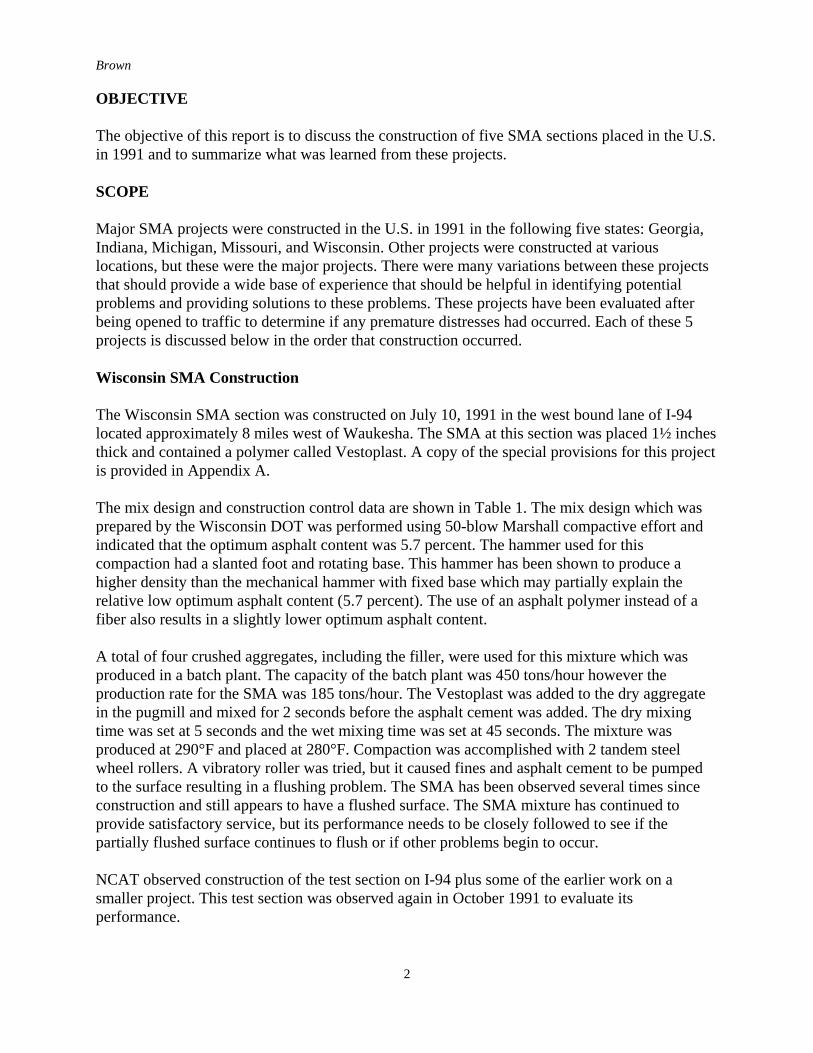
Table 1. Mix Design and Plant Production Data for SMA in WisconsinProperty Mix Design Plant Produced
MaterialGradation
3/4 inch 100 1001/2 inch 94 943/8 inch 70 69No. 4 28 28No. 8 20 20No. 16 16 16No. 30 14 14No. 50 13 13No. 100 12 12No. 200 10.8 10
Asphalt Content, % 5.7 5.5Lab Compacted Voids, % 3.1 3.5In-Place Voids, % --- 6.8Asphalt Cement Grade 85-100 pen 85-100 penVoids in Mineral Aggregate, % --- 17.3Vestoplast, % of Asphalt Cement 7.0 7.0
Georgia SMA Construction
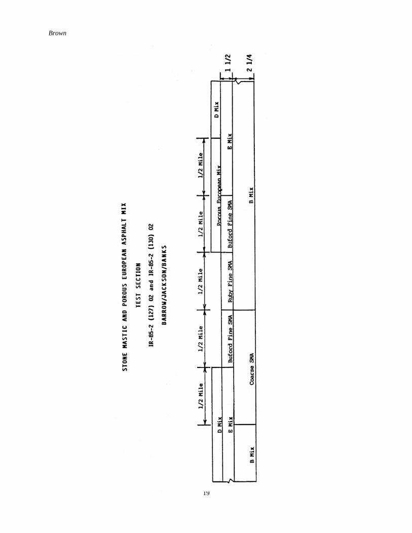
The SMA sections in Georgia were placed on I-85 in Jackson County in the outside Southboundlane between mileposts 129.5 and 132. The SMA binder course was placed on July 31, 1991, andthe SMA surface course mixes were placed September 3 and September 17, 1991. The bindercourse was subjected to traffic until covered with the SMA surface mixture. This roadway had anAADT count of 35,000 with approximately 40% trucks. A layout of the test sections is shown inAppendix B.
SMA test sections at this site consisted of a fine SMA (aggregate 1) over a coarse SMA and afine SMA (aggregate 2) over a dense graded binder course mix. The binder course and coarseSMA mixes were 2.25 inches thick and the two fine SMA mixtures were 1.5 inches thick.
The mix design properties and mix production properties as developed by the Georgia DOT areshown in Tables 2 and 3 respectively. There are some minor differences between the SMAproperties of the designed mix and properties of the produced mix. These differences indicate theneed for checking mix properties during construction and modifying the mixture as needed tomeet desired properties.
Brown
4
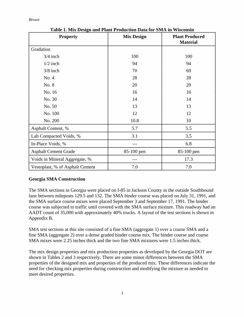
Table 2. Mix Designs for Georgia SMAsTest Property Coarse
SMAFine SMA
Aggregate 1Fine SMA
Aggregate 2Gradation
3/4 inch 1001/2 inch 62 100 1003/8 inch 42 78 81No. 4 --- 36 37No. 8 20 23 23No. 16 --- --- ---No. 30 --- --- ---No. 50 16 13 12No. 100 --- --- ---No. 200 10 8 8
Asphalt Cement Grade AC-30 AC-30 AC-30Asphalt Cement Additive (Novophalt), % of AC 5.2 5.2 5.2Asphalt Content, % 5.8 5.5/5.8 5.8/6.0Quantity of Fiber (Inorphil), % of AC 8.0 7.4-7.0 7.4-5.0Quantity of Fiber (Inorphil), % of Total Mix 0.42 0.38-0.36 0.38-0.26Voids in Total Mix, % 4.0 3.9/3.2* 4.0/3.8*
* This reflects % voids at the AC contents shown above.
Table 3. Average Properties of Plant Produced SMAs in GeorgiaProperty Coarse
SMAFine SMA
Aggregate 1Fine SMA
Aggregate 2Gradation
3/4 inch 100 100 1001/2 inch 64 99 993/8 inch 39 85 83No. 4 --- 45 38No. 8 22 29 24No. 50 18 19 16No. 200 10.0 10.0 10.1
Asphalt Content, % 5.7 5.5 5.6Lab Compacted Voids, % 4.1 4.1 6.2In-Place Voids, % 4.0 7.0 6.3
Brown
5
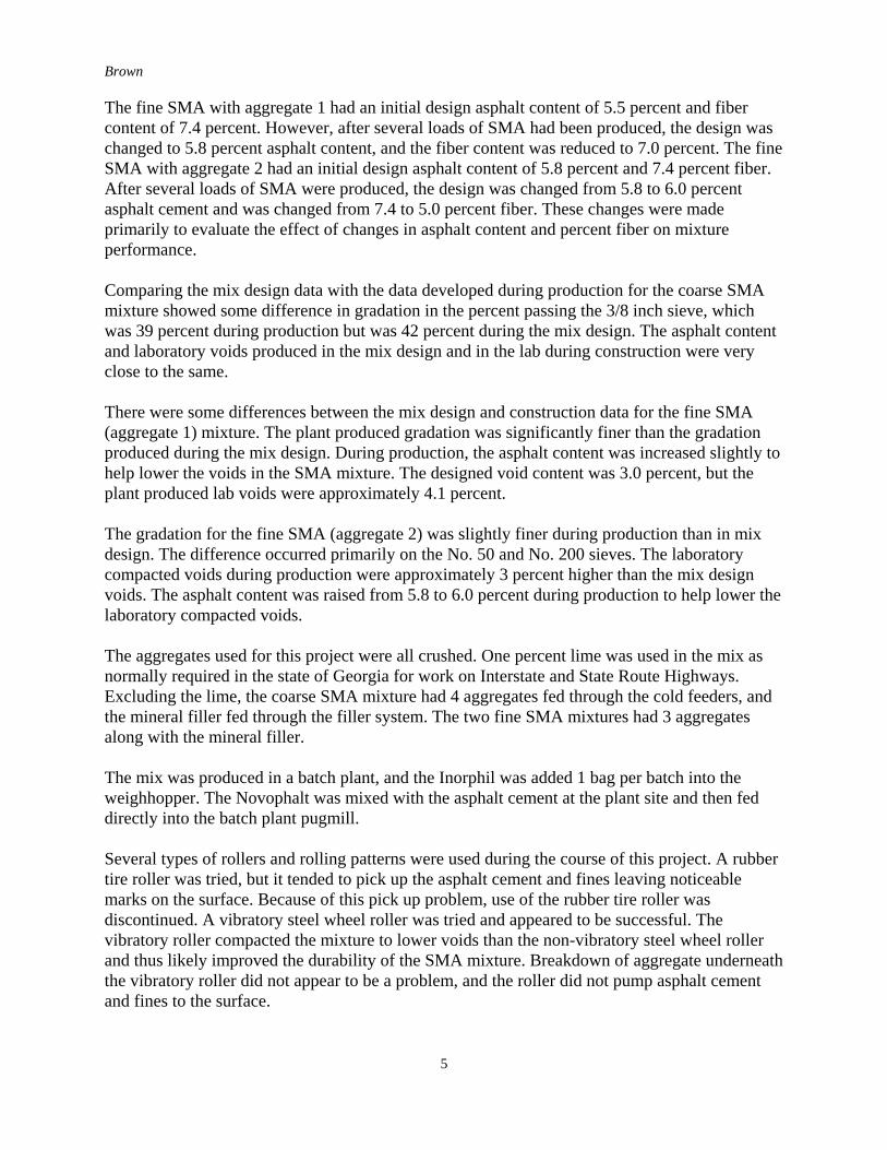
The fine SMA with aggregate 1 had an initial design asphalt content of 5.5 percent and fibercontent of 7.4 percent. However, after several loads of SMA had been produced, the design waschanged to 5.8 percent asphalt content, and the fiber content was reduced to 7.0 percent. The fineSMA with aggregate 2 had an initial design asphalt content of 5.8 percent and 7.4 percent fiber.After several loads of SMA were produced, the design was changed from 5.8 to 6.0 percentasphalt cement and was changed from 7.4 to 5.0 percent fiber. These changes were madeprimarily to evaluate the effect of changes in asphalt content and percent fiber on mixtureperformance.
Comparing the mix design data with the data developed during production for the coarse SMAmixture showed some difference in gradation in the percent passing the 3/8 inch sieve, whichwas 39 percent during production but was 42 percent during the mix design. The asphalt contentand laboratory voids produced in the mix design and in the lab during construction were veryclose to the same.
There were some differences between the mix design and construction data for the fine SMA(aggregate 1) mixture. The plant produced gradation was significantly finer than the gradationproduced during the mix design. During production, the asphalt content was increased slightly tohelp lower the voids in the SMA mixture. The designed void content was 3.0 percent, but theplant produced lab voids were approximately 4.1 percent.
The gradation for the fine SMA (aggregate 2) was slightly finer during production than in mixdesign. The difference occurred primarily on the No. 50 and No. 200 sieves. The laboratorycompacted voids during production were approximately 3 percent higher than the mix designvoids. The asphalt content was raised from 5.8 to 6.0 percent during production to help lower thelaboratory compacted voids.
The aggregates used for this project were all crushed. One percent lime was used in the mix asnormally required in the state of Georgia for work on Interstate and State Route Highways.Excluding the lime, the coarse SMA mixture had 4 aggregates fed through the cold feeders, andthe mineral filler fed through the filler system. The two fine SMA mixtures had 3 aggregatesalong with the mineral filler.
The mix was produced in a batch plant, and the Inorphil was added 1 bag per batch into theweighhopper. The Novophalt was mixed with the asphalt cement at the plant site and then feddirectly into the batch plant pugmill.
Several types of rollers and rolling patterns were used during the course of this project. A rubbertire roller was tried, but it tended to pick up the asphalt cement and fines leaving noticeablemarks on the surface. Because of this pick up problem, use of the rubber tire roller wasdiscontinued. A vibratory steel wheel roller was tried and appeared to be successful. Thevibratory roller compacted the mixture to lower voids than the non-vibratory steel wheel rollerand thus likely improved the durability of the SMA mixture. Breakdown of aggregate underneaththe vibratory roller did not appear to be a problem, and the roller did not pump asphalt cementand fines to the surface.
Brown
6
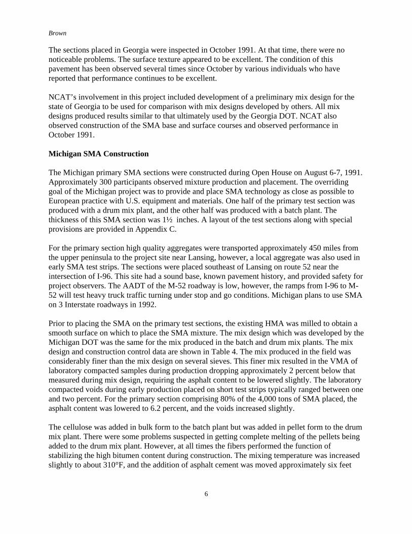
The sections placed in Georgia were inspected in October 1991. At that time, there were nonoticeable problems. The surface texture appeared to be excellent. The condition of thispavement has been observed several times since October by various individuals who havereported that performance continues to be excellent.
NCAT’s involvement in this project included development of a preliminary mix design for thestate of Georgia to be used for comparison with mix designs developed by others. All mixdesigns produced results similar to that ultimately used by the Georgia DOT. NCAT alsoobserved construction of the SMA base and surface courses and observed performance inOctober 1991.
Michigan SMA Construction
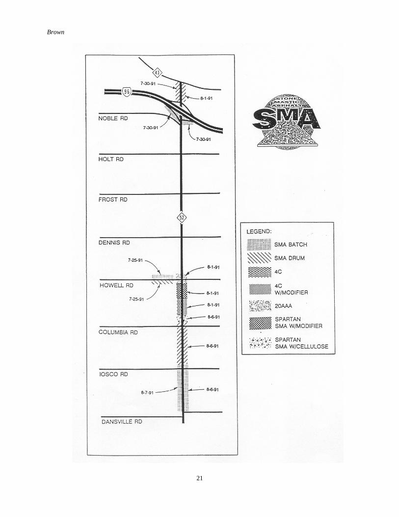
The Michigan primary SMA sections were constructed during Open House on August 6-7, 1991.Approximately 300 participants observed mixture production and placement. The overridinggoal of the Michigan project was to provide and place SMA technology as close as possible toEuropean practice with U.S. equipment and materials. One half of the primary test section wasproduced with a drum mix plant, and the other half was produced with a batch plant. Thethickness of this SMA section was 1½ inches. A layout of the test sections along with specialprovisions are provided in Appendix C.
For the primary section high quality aggregates were transported approximately 450 miles fromthe upper peninsula to the project site near Lansing, however, a local aggregate was also used inearly SMA test strips. The sections were placed southeast of Lansing on route 52 near theintersection of I-96. This site had a sound base, known pavement history, and provided safety forproject observers. The AADT of the M-52 roadway is low, however, the ramps from I-96 to M-52 will test heavy truck traffic turning under stop and go conditions. Michigan plans to use SMAon 3 Interstate roadways in 1992.
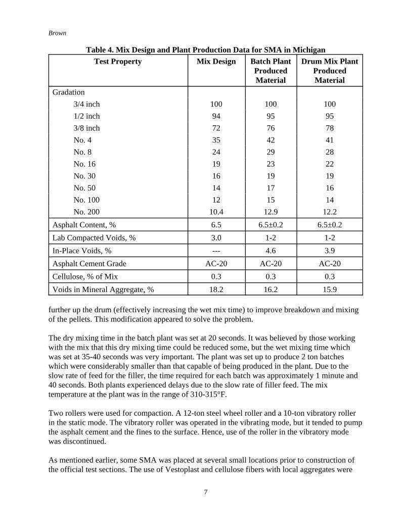
Prior to placing the SMA on the primary test sections, the existing HMA was milled to obtain asmooth surface on which to place the SMA mixture. The mix design which was developed by theMichigan DOT was the same for the mix produced in the batch and drum mix plants. The mixdesign and construction control data are shown in Table 4. The mix produced in the field wasconsiderably finer than the mix design on several sieves. This finer mix resulted in the VMA oflaboratory compacted samples during production dropping approximately 2 percent below thatmeasured during mix design, requiring the asphalt content to be lowered slightly. The laboratorycompacted voids during early production placed on short test strips typically ranged between oneand two percent. For the primary section comprising 80% of the 4,000 tons of SMA placed, theasphalt content was lowered to 6.2 percent, and the voids increased slightly.
The cellulose was added in bulk form to the batch plant but was added in pellet form to the drummix plant. There were some problems suspected in getting complete melting of the pellets beingadded to the drum mix plant. However, at all times the fibers performed the function ofstabilizing the high bitumen content during construction. The mixing temperature was increasedslightly to about 310°F, and the addition of asphalt cement was moved approximately six feet
Brown
7
Table 4. Mix Design and Plant Production Data for SMA in MichiganTest Property Mix Design Batch Plant
ProducedMaterial
Drum Mix PlantProducedMaterial
Gradation3/4 inch 100 100 1001/2 inch 94 95 953/8 inch 72 76 78No. 4 35 42 41No. 8 24 29 28No. 16 19 23 22No. 30 16 19 19No. 50 14 17 16No. 100 12 15 14No. 200 10.4 12.9 12.2
Asphalt Content, % 6.5 6.5±0.2 6.5±0.2Lab Compacted Voids, % 3.0 1-2 1-2In-Place Voids, % --- 4.6 3.9Asphalt Cement Grade AC-20 AC-20 AC-20Cellulose, % of Mix 0.3 0.3 0.3Voids in Mineral Aggregate, % 18.2 16.2 15.9
further up the drum (effectively increasing the wet mix time) to improve breakdown and mixingof the pellets. This modification appeared to solve the problem.
The dry mixing time in the batch plant was set at 20 seconds. It was believed by those workingwith the mix that this dry mixing time could be reduced some, but the wet mixing time whichwas set at 35-40 seconds was very important. The plant was set up to produce 2 ton batcheswhich were considerably smaller than that capable of being produced in the plant. Due to theslow rate of feed for the filler, the time required for each batch was approximately 1 minute and40 seconds. Both plants experienced delays due to the slow rate of filler feed. The mixtemperature at the plant was in the range of 310-315°F.
Two rollers were used for compaction. A 12-ton steel wheel roller and a 10-ton vibratory rollerin the static mode. The vibratory roller was operated in the vibrating mode, but it tended to pumpthe asphalt cement and the fines to the surface. Hence, use of the roller in the vibratory modewas discontinued.
As mentioned earlier, some SMA was placed at several small locations prior to construction ofthe official test sections. The use of Vestoplast and cellulose fibers with local aggregates were
Brown
8
tried in some of these earlier small projects. These small projects were constructed primarily tobecome familiar with the materials and construction methods before construction of the primarytest sections, but these small projects will allow comparison of performance for the twoaggregate sources as well as the fiber versus polymer modified SMA. Details of these smallerprojects are not provided in this report.
NCAT observed construction of this SMA section and observed performance in October 1991. Alaboratory study using the materials from this project has been completed and reportedelsewhere. This study the sensitivity of SMA mixtures to a change in material measuredproportions.
Missouri SMA Construction
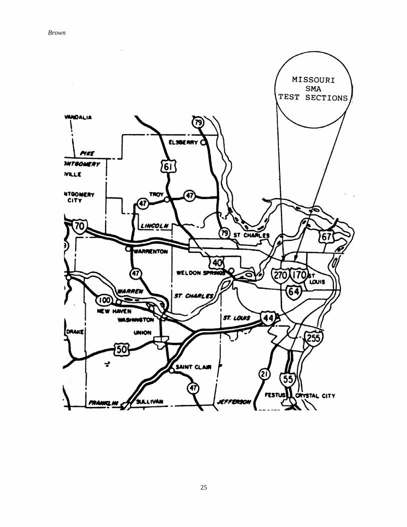
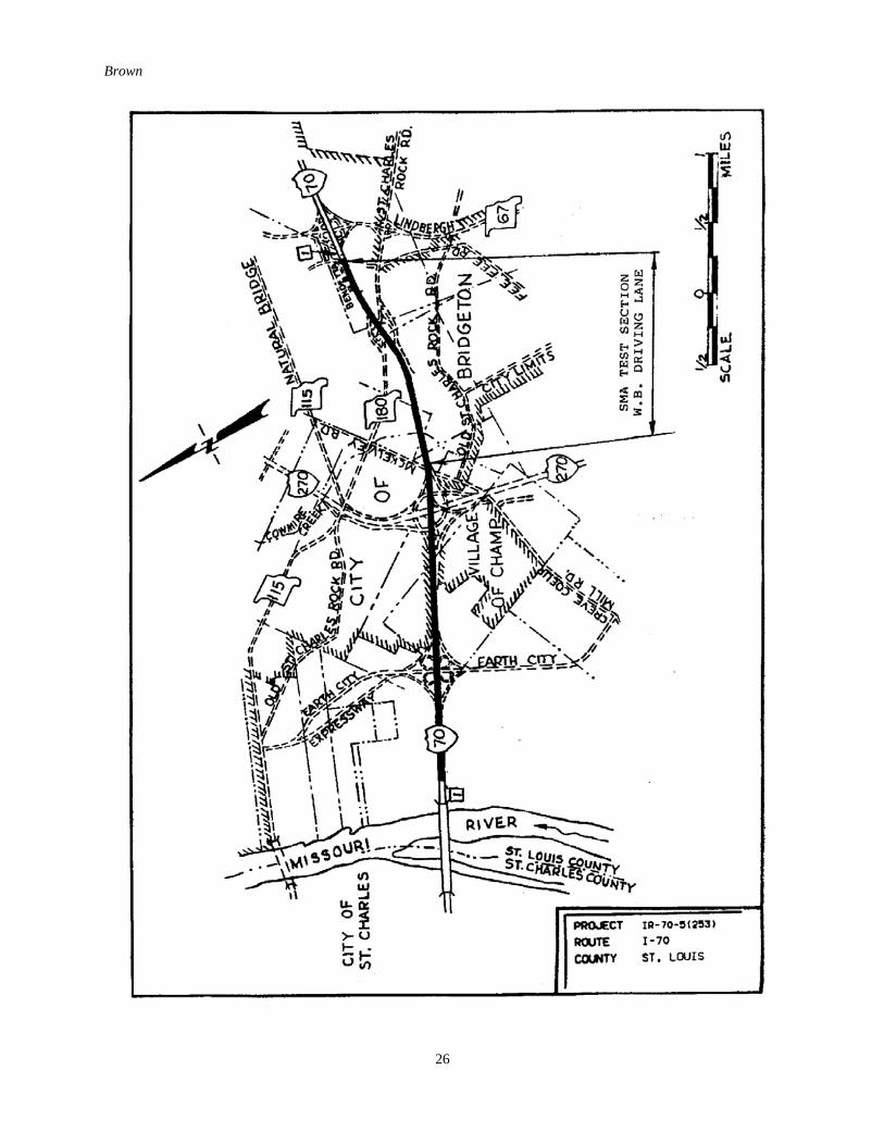
The Missouri SMA section was constructed in the westbound outer lane of I-70 in St. Louis.Some of the SMA mixture was produced using cellulose fibers (Arbocel), and some wasproduced with mineral fibers (Inorphil). The AADT on this road was 55,000 with approximately10% trucks. The sections were constructed on September 4 and 5 at a thickness of 1½ inches. Alayout and special provisions for this project are provided in Appendix D.
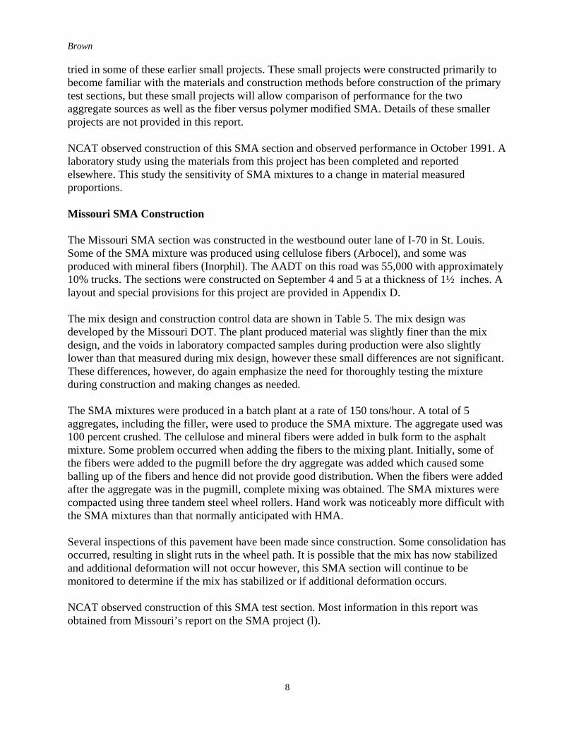
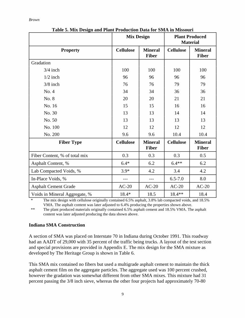
The mix design and construction control data are shown in Table 5. The mix design wasdeveloped by the Missouri DOT. The plant produced material was slightly finer than the mixdesign, and the voids in laboratory compacted samples during production were also slightlylower than that measured during mix design, however these small differences are not significant.These differences, however, do again emphasize the need for thoroughly testing the mixtureduring construction and making changes as needed.
The SMA mixtures were produced in a batch plant at a rate of 150 tons/hour. A total of 5aggregates, including the filler, were used to produce the SMA mixture. The aggregate used was100 percent crushed. The cellulose and mineral fibers were added in bulk form to the asphaltmixture. Some problem occurred when adding the fibers to the mixing plant. Initially, some ofthe fibers were added to the pugmill before the dry aggregate was added which caused someballing up of the fibers and hence did not provide good distribution. When the fibers were addedafter the aggregate was in the pugmill, complete mixing was obtained. The SMA mixtures werecompacted using three tandem steel wheel rollers. Hand work was noticeably more difficult withthe SMA mixtures than that normally anticipated with HMA.
Several inspections of this pavement have been made since construction. Some consolidation hasoccurred, resulting in slight ruts in the wheel path. It is possible that the mix has now stabilizedand additional deformation will not occur however, this SMA section will continue to bemonitored to determine if the mix has stabilized or if additional deformation occurs.
NCAT observed construction of this SMA test section. Most information in this report wasobtained from Missouri’s report on the SMA project (l).
Brown
9
Table 5. Mix Design and Plant Production Data for SMA in MissouriMix Design Plant Produced
MaterialProperty Cellulose Mineral
FiberCellulose Mineral
FiberGradation
3/4 inch 100 100 100 1001/2 inch 96 96 96 963/8 inch 76 76 79 79No. 4 34 34 36 36No. 8 20 20 21 21No. 16 15 15 16 16No. 30 13 13 14 14No. 50 13 13 13 13No. 100 12 12 12 12No. 200 9.6 9.6 10.4 10.4
Fiber Type Cellulose MineralFiber
Cellulose MineralFiber
Fiber Content, % of total mix 0.3 0.3 0.3 0.5Asphalt Content, % 6.4* 6.2 6.4** 6.2Lab Compacted Voids, % 3.9* 4.2 3.4 4.2In-Place Voids, % --- --- 6.5-7.0 8.0Asphalt Cement Grade AC-20 AC-20 AC-20 AC-20Voids in Mineral Aggregate, % 18.4* 18.5 18.4** 18.4
* The mix design with cellulose originally contained 6.5% asphalt, 3.8% lab compacted voids, and 18.5%VMA. The asphalt content was later adjusted to 6.4% producing the properties shown above.
** The plant produced materials originally contained 6.5% asphalt cement and 18.5% VMA. The asphaltcontent was later adjusted producing the data shown above.
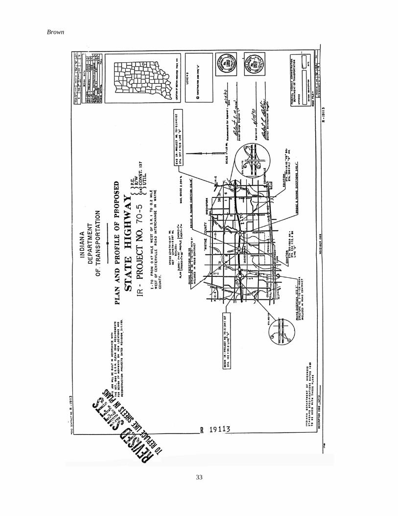
Indiana SMA Construction
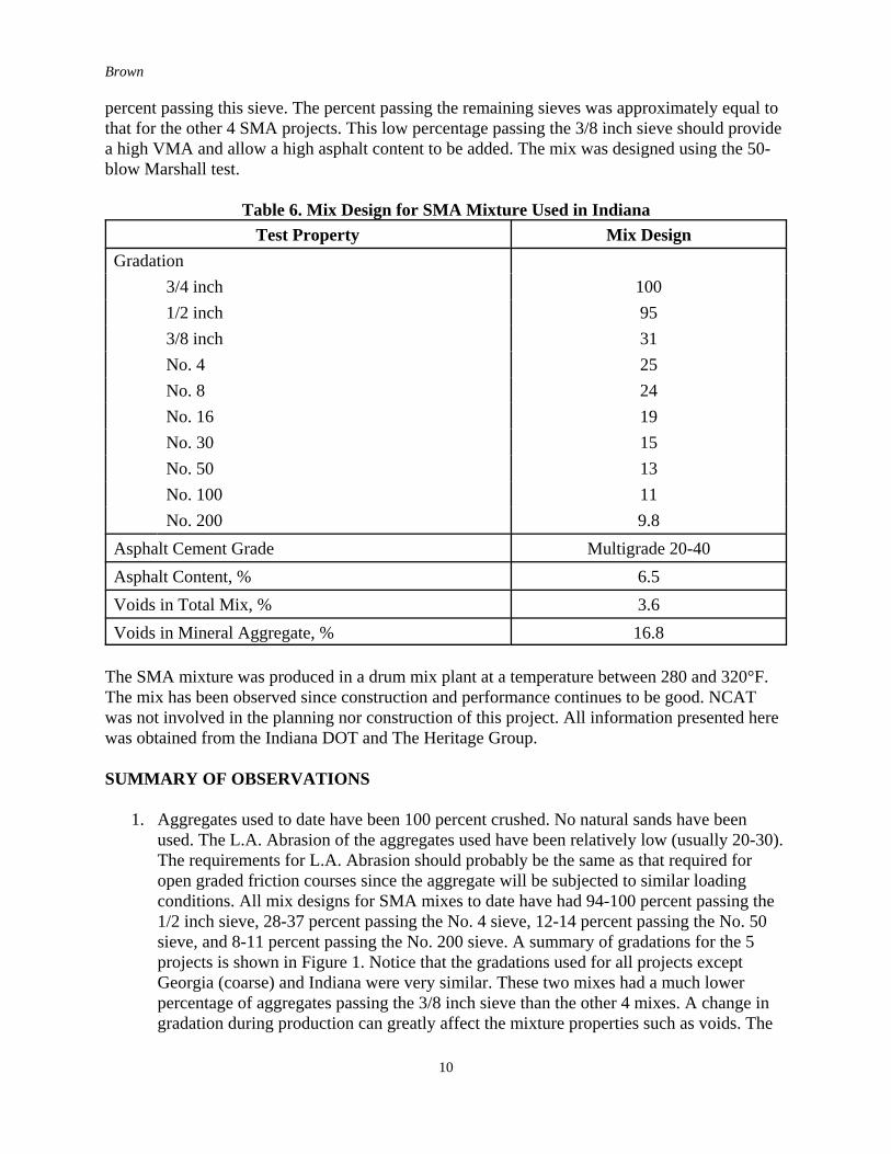
A section of SMA was placed on Interstate 70 in Indiana during October 1991. This roadwayhad an AADT of 29,000 with 35 percent of the traffic being trucks. A layout of the test sectionand special provisions are provided in Appendix E. The mix design for the SMA mixture asdeveloped by The Heritage Group is shown in Table 6.
This SMA mix contained no fibers but used a multigrade asphalt cement to maintain the thickasphalt cement film on the aggregate particles. The aggregate used was 100 percent crushed,however the gradation was somewhat different from other SMA mixes. This mixture had 31percent passing the 3/8 inch sieve, whereas the other four projects had approximately 70-80
Brown
10
percent passing this sieve. The percent passing the remaining sieves was approximately equal tothat for the other 4 SMA projects. This low percentage passing the 3/8 inch sieve should providea high VMA and allow a high asphalt content to be added. The mix was designed using the 50-blow Marshall test.
Table 6. Mix Design for SMA Mixture Used in IndianaTest Property Mix Design
Gradation3/4 inch 1001/2 inch 953/8 inch 31No. 4 25No. 8 24No. 16 19No. 30 15No. 50 13No. 100 11No. 200 9.8
Asphalt Cement Grade Multigrade 20-40Asphalt Content, % 6.5Voids in Total Mix, % 3.6Voids in Mineral Aggregate, % 16.8
The SMA mixture was produced in a drum mix plant at a temperature between 280 and 320°F.The mix has been observed since construction and performance continues to be good. NCATwas not involved in the planning nor construction of this project. All information presented herewas obtained from the Indiana DOT and The Heritage Group.
SUMMARY OF OBSERVATIONS
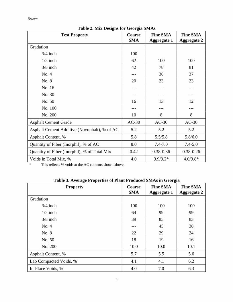
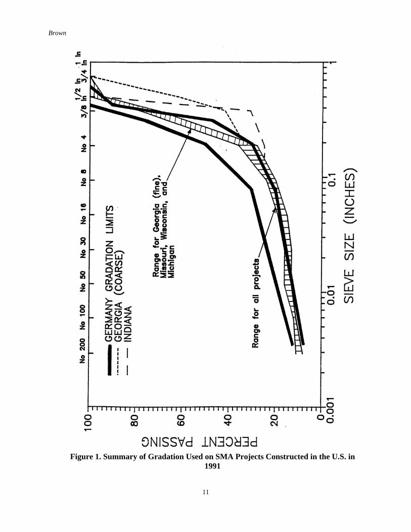
1. Aggregates used to date have been 100 percent crushed. No natural sands have beenused. The L.A. Abrasion of the aggregates used have been relatively low (usually 20-30).The requirements for L.A. Abrasion should probably be the same as that required foropen graded friction courses since the aggregate will be subjected to similar loadingconditions. All mix designs for SMA mixes to date have had 94-100 percent passing the1/2 inch sieve, 28-37 percent passing the No. 4 sieve, 12-14 percent passing the No. 50sieve, and 8-11 percent passing the No. 200 sieve. A summary of gradations for the 5projects is shown in Figure 1. Notice that the gradations used for all projects exceptGeorgia (coarse) and Indiana were very similar. These two mixes had a much lowerpercentage of aggregates passing the 3/8 inch sieve than the other 4 mixes. A change ingradation during production can greatly affect the mixture properties such as voids. The
Brown
11
Figure 1. Summary of Gradation Used on SMA Projects Constructed in the U.S. in1991
Brown
12
voids in SMA mixtures appear to be more affected by gradation changes especially onthe No. 4 and No. 8 sieves than the voids in dense graded HMA.
2. The asphalt cement grades used to date have been AC-20, AC-30, 85-100 pen, andMultigrade asphalt cement. Two of the asphalt cements contained modifiers (Novophaltin Georgia and Vestoplast in Wisconsin). The additive content was 5.2 % of AC forNovophalt and 7.0% of AC for Vestoplast.
3. Two types of fibers have been used in the U.S. These fibers include cellulose (Arbocel)in Missouri, Michigan, and Wisconsin and mineral fiber (Inorphil) in Georgia andMissouri. The fiber content used so far has been 0.3 percent of total mix for cellulose and7-8 percent of asphalt cement for the mineral fiber. Fibers have been added in bulk inbatch plants and in pellet form in drum mix plants. The pellets contain a hard baseasphalt cement which must be considered when computing the fiber content being added.On one of the projects, some problems were encountered when it appeared the pellets didnot completely breakdown in the mix. However at all times the fibers performed thefunction of stabilizing the relatively high bitumen content during the constructionprocess. Complete pellet breakdown was achieved, but those involved with production ofSMA should ensure this problem does not occur on future projects.
4. All mix designs in the U.S. have been performed with 50 blows with the Marshallhammer. SMA mixtures compact quickly, so additional blows would not likelysignificantly increase the density. Additional compaction would also cause excessivebreakdown in the aggregate. SMA mixtures have been designed to have as low as 3percent voids in some cases and as high as 4 percent voids in others. Hotter climatesshould probably design closer to 4 percent voids, and colder climates should designcloser to 3 percent voids. The voids in laboratory compacted samples must be determinedduring construction and the mix modified, if necessary, to ensure the desired void contentis obtained. SMA mixtures appear to be able to tolerate lower voids than dense gradedHMA, but care must be exercised to keep voids above 3 percent to provide some marginof safety against rutting.
5. Batch plants and drum mix plants have been used successfully to produce SMA mixtures.Mixtures have been produced using 3-5 individual stockpiles. Aggregate gradations havegenerally been slightly finer during construction than in mix design, which tends to closethe voids. Hence, adjustments must be made during construction to obtain the desiredvoids. The addition of high filler content (typically 7-12 percent depending on gradationof filler) may reduce the production rate if provisions are not made at the plant to addhigh filler content. On one of the projects production in a 750 TPH drum mix plant wasreduced to 315 TPH due to limitations of the mineral filler system. Fibers have beenadded in bulk form directly into the pugmill in a batch plant and are fed in pellet formthrough the RAP feeder (1/2 way down drum) for a drum mix plant. A longer mixingtime is required for SMA mixtures containing fibers than that required for dense gradedHMA. The dry mixing time may require a slight increase in time but it is more importantthat the wet mixing time be increased to a satisfactory level. Total mixing times havetypically been 1 minute or less per batch.
6. All SMA surface mixes to date have been 1½ inches thick. In at least two cases, SMAbinder courses were covered with SMA surface courses. Most mixes have beencompacted with steel wheel non-vibratory rollers. Vibratory rollers have been tried withsuccess on some jobs but have created problems on other projects. Rubber tire rollers
Brown
13
have been tried but appeared to pick up too much asphalt cement and fines. Based on thisobservation, rubber tire rollers should not be used to compact SMA mixtures. Initial in-place voids have typically been in the 5-7 percent range.
7. The Europeans often use fine chips on the surface of SMA mixtures to improve initialskid resistance. Chips have been tried in at least one place in the United States, but itappears that the chips are not needed. As the SMA mixes age and the surface asphaltcement is worn off the microtexture begins to provide a good frictional surface and, theskid resistance tends to improve.
8. Performance to date has been good, however, the SMA mixtures have not been downlong enough to fully evaluate performance. Some apparent flushing has occurred on oneproject, and some consolidation on another, but this does not appear to have causedsignificant problems to date.
RECOMMENDATIONS
1. A generic specification for SMA is needed for the mixture and for the variouscomponents (fibers, polymers).
2. Performance data for SMA must be collected during the next few years to help identifyproblems and to provide answers to these problems. The cost effectiveness of SMA needsto be determined.
3. A task group is needed to provide some direction to use of SMA in the U.S. This taskgroup, as a minimum, should consist of FHWA, State DOTS, and Industry.
REFERENCES
1. McDaniel, Pat. “Stone Mastic Asphalt-Missouri’s Experimental Project Using EuropeanTechnology,” MO.91-05, February 1992.

Brown
14
APPENDIX A
SMA Mixtures in Wisconsin
Brown
15
Wisconsin DOTSMA
STONE MASTIC ASPHALT PROVISIONS
Materials Specifications
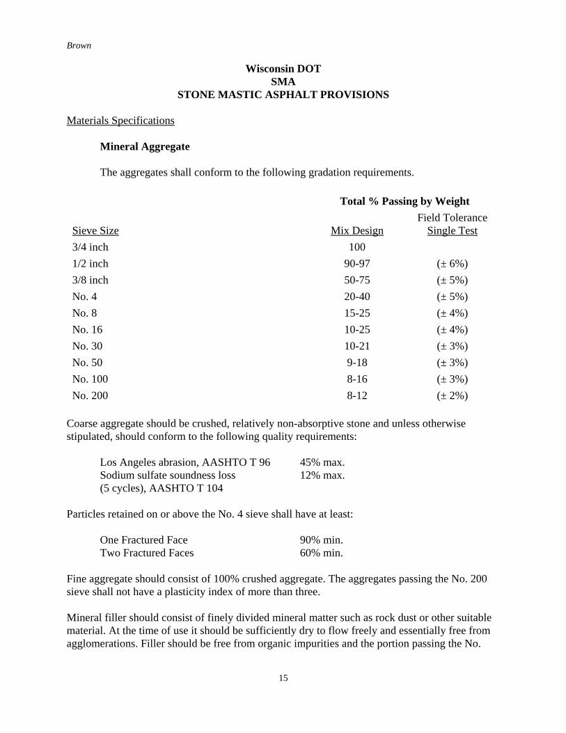
Mineral Aggregate
The aggregates shall conform to the following gradation requirements.
Total % Passing by Weight
Sieve Size Mix DesignField Tolerance
Single Test3/4 inch 1001/2 inch 90-97 (± 6%)3/8 inch 50-75 (± 5%)No. 4 20-40 (± 5%)No. 8 15-25 (± 4%)No. 16 10-25 (± 4%)No. 30 10-21 (± 3%)No. 50 9-18 (± 3%)No. 100 8-16 (± 3%)No. 200 8-12 (± 2%)
Coarse aggregate should be crushed, relatively non-absorptive stone and unless otherwisestipulated, should conform to the following quality requirements:
Los Angeles abrasion, AASHTO T 96 45% max.Sodium sulfate soundness loss 12% max.(5 cycles), AASHTO T 104
Particles retained on or above the No. 4 sieve shall have at least:
One Fractured Face 90% min.Two Fractured Faces 60% min.
Fine aggregate should consist of 100% crushed aggregate. The aggregates passing the No. 200sieve shall not have a plasticity index of more than three.
Mineral filler should consist of finely divided mineral matter such as rock dust or other suitablematerial. At the time of use it should be sufficiently dry to flow freely and essentially free fromagglomerations. Filler should be free from organic impurities and the portion passing the No.
Brown
16
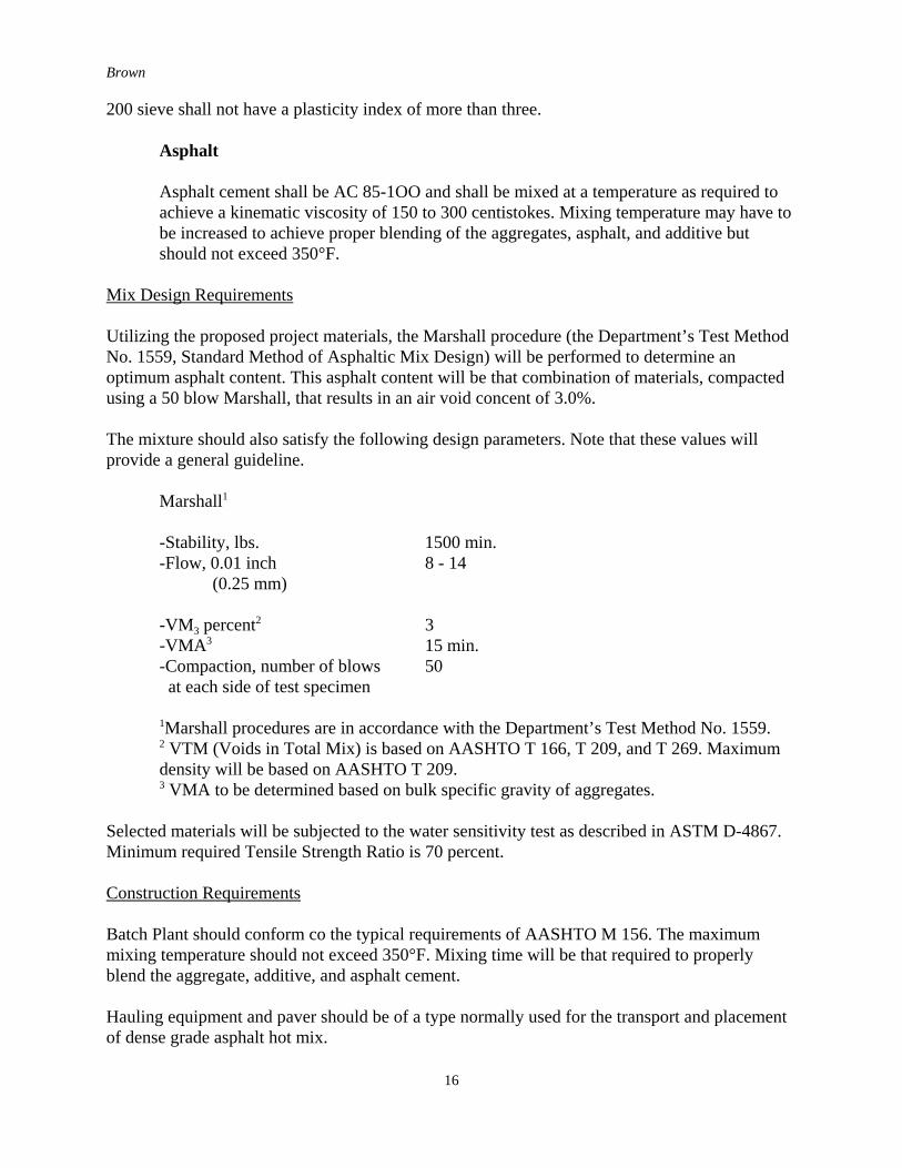
200 sieve shall not have a plasticity index of more than three.
Asphalt
Asphalt cement shall be AC 85-1OO and shall be mixed at a temperature as required toachieve a kinematic viscosity of 150 to 300 centistokes. Mixing temperature may have tobe increased to achieve proper blending of the aggregates, asphalt, and additive butshould not exceed 350°F.
Mix Design Requirements
Utilizing the proposed project materials, the Marshall procedure (the Department’s Test MethodNo. 1559, Standard Method of Asphaltic Mix Design) will be performed to determine anoptimum asphalt content. This asphalt content will be that combination of materials, compactedusing a 50 blow Marshall, that results in an air void concent of 3.0%.
The mixture should also satisfy the following design parameters. Note that these values willprovide a general guideline.
Marshall1
-Stability, lbs. 1500 min.-Flow, 0.01 inch 8 - 14
(0.25 mm)
-VM3 percent2 3-VMA3 15 min.-Compaction, number of blows 50 at each side of test specimen
1Marshall procedures are in accordance with the Department’s Test Method No. 1559.2 VTM (Voids in Total Mix) is based on AASHTO T 166, T 209, and T 269. Maximumdensity will be based on AASHTO T 209.3 VMA to be determined based on bulk specific gravity of aggregates.
Selected materials will be subjected to the water sensitivity test as described in ASTM D-4867.Minimum required Tensile Strength Ratio is 70 percent.
Construction Requirements
Batch Plant should conform co the typical requirements of AASHTO M 156. The maximummixing temperature should not exceed 350°F. Mixing time will be that required to properlyblend the aggregate, additive, and asphalt cement.
Hauling equipment and paver should be of a type normally used for the transport and placementof dense grade asphalt hot mix.
Brown
17
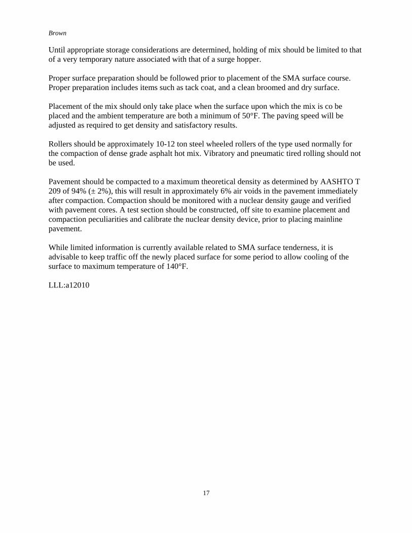
Until appropriate storage considerations are determined, holding of mix should be limited to thatof a very temporary nature associated with that of a surge hopper.
Proper surface preparation should be followed prior to placement of the SMA surface course.Proper preparation includes items such as tack coat, and a clean broomed and dry surface.
Placement of the mix should only take place when the surface upon which the mix is co beplaced and the ambient temperature are both a minimum of 50°F. The paving speed will beadjusted as required to get density and satisfactory results.
Rollers should be approximately 10-12 ton steel wheeled rollers of the type used normally forthe compaction of dense grade asphalt hot mix. Vibratory and pneumatic tired rolling should notbe used.
Pavement should be compacted to a maximum theoretical density as determined by AASHTO T209 of 94% (± 2%), this will result in approximately 6% air voids in the pavement immediatelyafter compaction. Compaction should be monitored with a nuclear density gauge and verifiedwith pavement cores. A test section should be constructed, off site to examine placement andcompaction peculiarities and calibrate the nuclear density device, prior to placing mainlinepavement.
While limited information is currently available related to SMA surface tenderness, it isadvisable to keep traffic off the newly placed surface for some period to allow cooling of thesurface to maximum temperature of 140°F.
LLL:a12010
Brown
18
APPENDIX B
SMA in Georgia
Brown
19
Brown
20
APPENDIX C
SMA Mixtures in Michigan
Brown
21
Brown
22
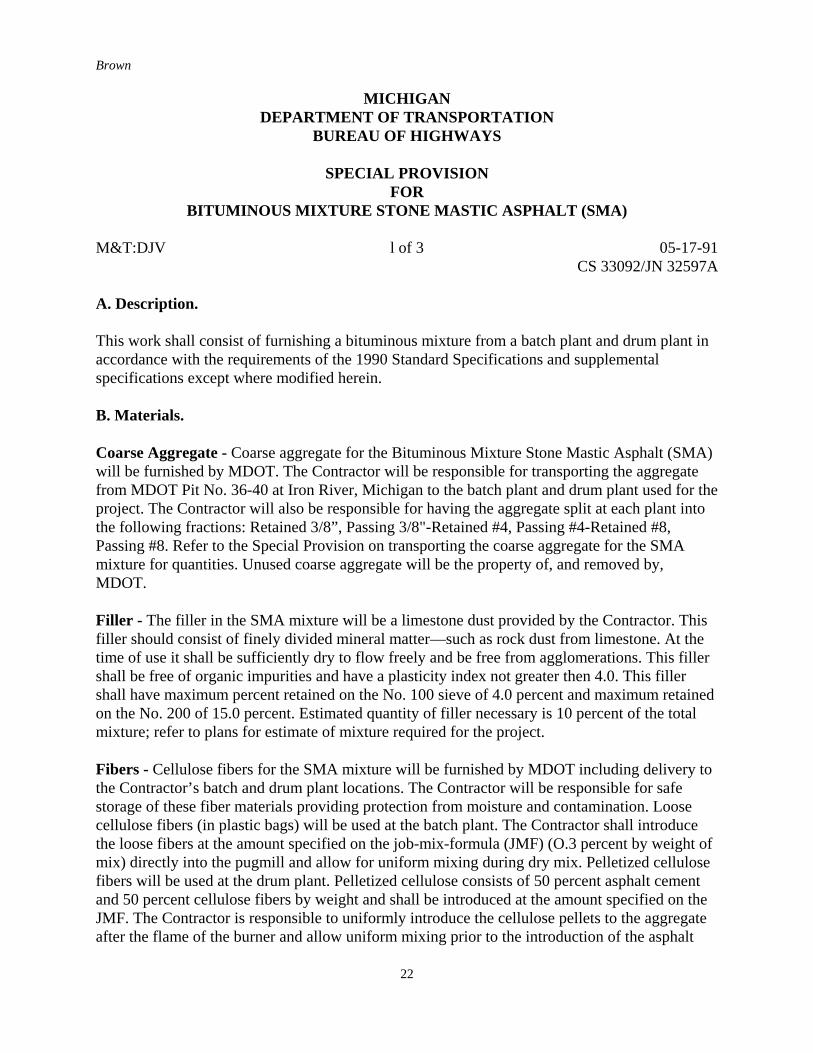
MICHIGANDEPARTMENT OF TRANSPORTATION
BUREAU OF HIGHWAYS
SPECIAL PROVISIONFOR
BITUMINOUS MIXTURE STONE MASTIC ASPHALT (SMA)
M&T:DJV l of 3 05-17-91CS 33092/JN 32597A
A. Description.
This work shall consist of furnishing a bituminous mixture from a batch plant and drum plant inaccordance with the requirements of the 1990 Standard Specifications and supplementalspecifications except where modified herein.
B. Materials.
Coarse Aggregate - Coarse aggregate for the Bituminous Mixture Stone Mastic Asphalt (SMA)will be furnished by MDOT. The Contractor will be responsible for transporting the aggregatefrom MDOT Pit No. 36-40 at Iron River, Michigan to the batch plant and drum plant used for theproject. The Contractor will also be responsible for having the aggregate split at each plant intothe following fractions: Retained 3/8”, Passing 3/8"-Retained #4, Passing #4-Retained #8,Passing #8. Refer to the Special Provision on transporting the coarse aggregate for the SMAmixture for quantities. Unused coarse aggregate will be the property of, and removed by,MDOT.
Filler - The filler in the SMA mixture will be a limestone dust provided by the Contractor. Thisfiller should consist of finely divided mineral matter—such as rock dust from limestone. At thetime of use it shall be sufficiently dry to flow freely and be free from agglomerations. This fillershall be free of organic impurities and have a plasticity index not greater then 4.0. This fillershall have maximum percent retained on the No. 100 sieve of 4.0 percent and maximum retainedon the No. 200 of 15.0 percent. Estimated quantity of filler necessary is 10 percent of the totalmixture; refer to plans for estimate of mixture required for the project.
Fibers - Cellulose fibers for the SMA mixture will be furnished by MDOT including delivery tothe Contractor’s batch and drum plant locations. The Contractor will be responsible for safestorage of these fiber materials providing protection from moisture and contamination. Loosecellulose fibers (in plastic bags) will be used at the batch plant. The Contractor shall introducethe loose fibers at the amount specified on the job-mix-formula (JMF) (O.3 percent by weight ofmix) directly into the pugmill and allow for uniform mixing during dry mix. Pelletized cellulosefibers will be used at the drum plant. Pelletized cellulose consists of 50 percent asphalt cementand 50 percent cellulose fibers by weight and shall be introduced at the amount specified on theJMF. The Contractor is responsible to uniformly introduce the cellulose pellets to the aggregateafter the flame of the burner and allow uniform mixing prior to the introduction of the asphalt

Brown
23
cement.
Asphalt Cement - Asphalt Cement for the SMA mixture shall be an AC-20 provided by theContractor from either Marathon or Amoco. The Contractor shall procure and store the AC-20 insuch a way that the batch plant and drum plant can run and place the SMA mixture on the sameday between 6 a.m. and 6 p.m. to accommodate tours of the demonstration site.
i. Measurement and Payment - The completed work for BITUMINOUS MIXTURE STONEMASTIC ASPHALT (SMA) will be measured and paid for at the contract unit price for thefollowing contract item (pay item).
Pay Item Pay Unit
Bituminous Mixture Stone Mastic Asphalt (SMA) . . . . Ton
Brown
24
APPENDIX D
SMA Mixtures in Missouri
Brown
25
Brown
26
Brown
27
Brown
28
Project: IR-70-5(253)
Route: I-70
County: St. Louis
As requested by the Missouri Highway and Transportation Department (MHTD), Fred WeberConstruction, Inc. agrees to furnish or perform the following to effect an asphaltic concreteoverlay test section.
1.0 DESCRIPTION. This item shall consist of the mix design, materials, equipment, andconstruction procedures necessary for producing and placing one course of stone masticasphalt (SMA) in conformity with the lines and grades shown on the plans or asdesignated by the engineer.
1.1 Unless otherwise stated, specification section references are from the version, in effect atthe time of this contract, of the Missouri Standard Specifications for HighwayConstruction and its supplements.
1.2 SMA shall meet all the requirements for asphaltic concrete in Sec 403 and Sec 404,except as modified herein.
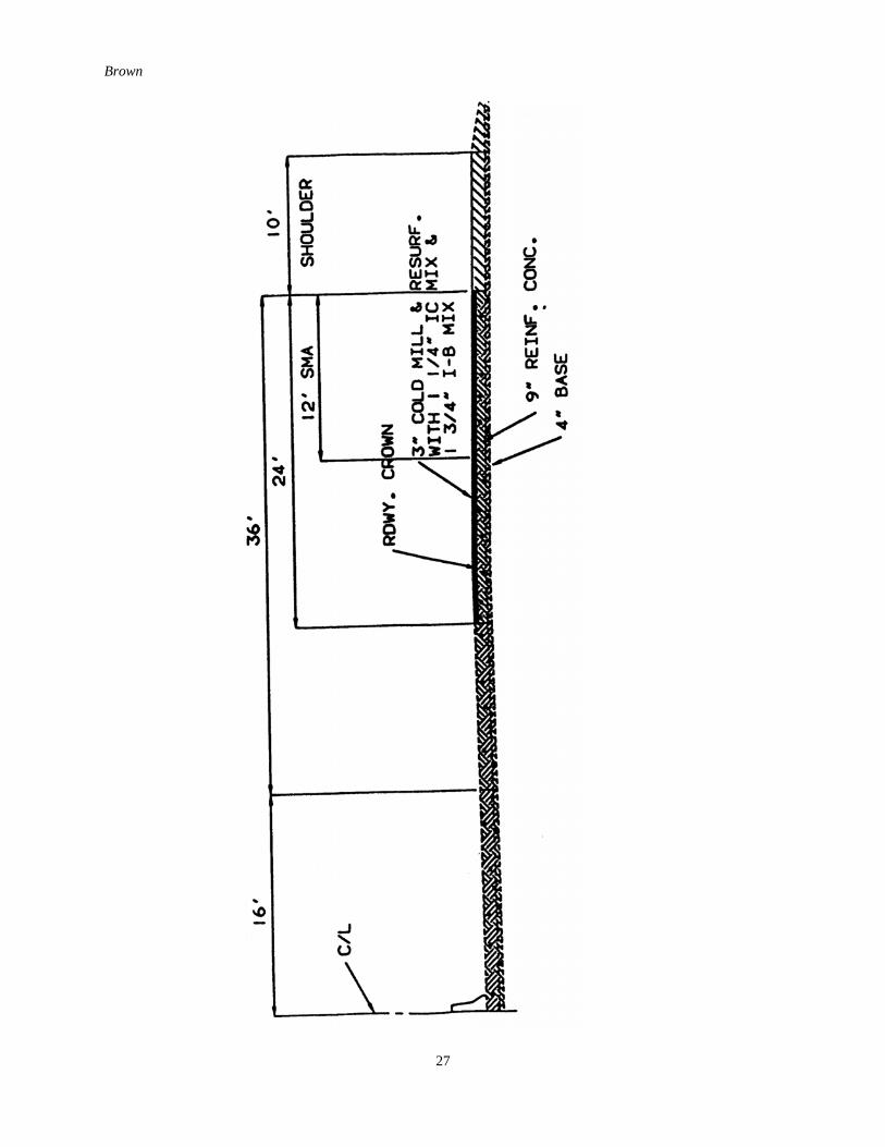
2.0 TEST SECTION. The test sections shall be in the westbound right lane from LindberghBoulevard to Route I-270. Each of the two test sections shall be 12 feet wide,approximately .9 mile long and shall be in the same lane end-to-end. The plan thicknessof SMA mixture, compacted in place shall be a minimum 1 1/4 inches.
3.0 MATERIALS. All materials shall conform to Division 1000, Materials Details unlessotherwise noted.
3.1 Asphalt Cement. The grade selected shall be determined by MHTD based on the CentralLaboratory test results. The contractor shall be responsible for procuring and storing theasphalt cement.
3.2 Fibers. Fibers shall be either cellulose fibers provided by ScanRoad, Inc. or mineralfibers provided by Fiberand Corporation. Loose cellulose or mineral fibers in plastic bagswill be used at the batch plant.
4.0 MIX DESIGN. The mix design will be performed by the Department’s CentralLaboratory and the job mix formula will be provided to the contractor.
4.1 Type and source of mixture components selected by the Department shall not be subjectto change. The amount of asphalt cement and fibers will be determined by the mixdesign.
Brown
29
4.2 Prior to mixing with fibers and asphalt cement, the total combined aggregate, includingmineral filler, shall meet the following gradation for the SMA mixture.
Percent Passing by WeightSieve Size SMA Tolerance3/4 inch 100 ---1/2 inch 96 ± 5.03/8 inch 76 ± 4.0No. 4 33 ± 3.0No. 8 20 ± 3.0No. 16 15 ± 3.0No. 30 14 ± 3.0No. 50 13 ± 2.0No. 100 12 ± 2.0No. 200 10 ± 2.0
4.2.1 The addition of hydrated lime will not be required.
5.0 EQUIPMENT. All equipment shall conform to Sec 403 and 404 unless otherwise noted.
5.1 Mixing Plant. A batch-type bituminous mixing plant shall be used in the production ofthe SMA mixture. The batch plant shall include a minimum of five cold aggregatefeeders excluding mineral filler and a minimum of four separate hot bins.
5.2 Rollers. Three-wheel or two-wheel tandem type steel wheel rollers shall be used. Allrollers shall be used in the static mode. A pneumatic tired roller will not be allowed.
6.0 PREPARATION OF MIXTURE. Preparation of the mixture shall be as set forth in Sec404, except for the following requirements or modifications.
6.1 The predetermined number of press-packs of fiber material required in the mixture shallbe added to the mineral aggregates either in the weigh hopper or in the pugmill. If addedin the pugmill, they shall be added at the same time or immediately after the mineralaggregates but before the asphalt cement is added.
6.2 If fibers are added in the weigh hopper, the mineral aggregates and fibers shall be drymixed for a maximum of 10 seconds. If the fibers are added to the mineral aggregates inthe pugmill, the minimum dry mix time shall be 15 seconds of which at least 6 secondsbut not more than 10 seconds shall be after all fibers have been added.
6.3 If mineral fibers are used in the SMA mixture, the wet mixing period shall be as specified
Brown
30
in Sec 404. If cellulose fibers are used, the wet mixing period shall be increased 10-20seconds to allow the cellulose fibers to expand and to ensure the adequate distribution ofthe fibers and binder.
6.4 Batch mixing temperature shall be started at 320 to 330°F and may be increased ifneeded to attain a homogeneous mixture, but the mixing temperature shall not exceed350°F or a temperature at which any smoking of the mix occurs, whichever is lower. Thefinal mixture, when discharged from the pugmill, shall have a minimum temperature of290°F and a moisture content not exceeding 0.50 percent by weight of mixture.
6.5 The dry and wet mixing times and batch mixing temperatures shall be as specified by theengineer.
6.6 The quantity of asphalt cement determined by calculation or tests on final mixture shallnot vary more than ± 0.5 percentage point from the approved job mix formula.
7.0 MIX STORAGE. Considering the tendency of the asphalt cement in SMA to drain fromthe mix, storage of the SMA mixture shall be limited to the intermittent holding of themix in the surge hopper while loading of trucks is performed.
8.0 CONSTRUCTION . Construction requirements shall be as set forth in Section 403,including application of tack and prime coat, except for the following modifications andadditional requirements.
8.1 Weather Limitations. The SMA mixture shall not be placed when either the airtemperature or the temperature of the surface on which the mixture is to be placed isbelow 50°F.
8.2 Transportation of Mixture. Maximum haul distance of the SMA mixture is 30 miles.Truck beds shall be clean of materials such as mud, dirt, and aggregates. Just prior toloading of the mixture, the truck bed shall be sprayed with a light application of anapproved truck bed release agent to reduce sticking of the mixture to the truck bed.
8.3 Spreading and Finishing. The mixture, when delivered to the spreading and finishingmachine, shall have a temperature of not less than 275°F and be within 25°F of thatspecified by the engineer. The screed heater shall be used at all times during placement ofthe mixture unless otherwise stated by the engineer. The pavers forward speed shall notexceed 40 feet per minute. The paver speed shall be such that delivery of mixture to thepaver is continuous.
8.4 Compaction. Rolling shall begin immediately after the mix has been placed. The engineerwill monitor compacted density with a nuclear density gauge. Rolling shall be continueduntil all roller marks are eliminated and a minimum density of 97 percent of a plantspecimen made in the proportions of the job mix formula in accordance with AASHTO T245, is attained. Density will be determined by a specific gravity method.
Brown
31
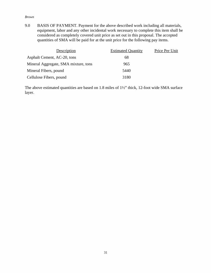
9.0 BASIS OF PAYMENT. Payment for the above described work including all materials,equipment, labor and any other incidental work necessary to complete this item shall beconsidered as completely covered unit price as set out in this proposal. The acceptedquantities of SMA will be paid for at the unit price for the following pay items.
Description Estimated Quantity Price Per UnitAsphalt Cement, AC-20, tons 68Mineral Aggregate, SMA mixture, tons 965Mineral Fibers, pound 5440Cellulose Fibers, pound 3180
The above estimated quantities are based on 1.8 miles of 1½” thick, 12-foot wide SMA surfacelayer.
Brown
32
APPENDIX E
SMA Mixtures in Indiana
Brown
33
Brown
34
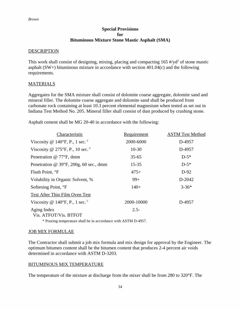
Special Provisionsfor
Bituminous Mixture Stone Mastic Asphalt (SMA)
DESCRIPTION
This work shall consist of designing, mixing, placing and compacting 165 #/yd2 of stone masticasphalt (SW+) bituminous mixture in accordance with section 401.04(c) and the followingrequirements.
MATERIALS
Aggregates for the SMA mixture shall consist of dolomite coarse aggregate, dolomite sand andmineral filler. The dolomite coarse aggregate and dolomite sand shall be produced fromcarbonate rock containing at least 10.3 percent elemental magnesium when tested as set out inIndiana Test Method No. 205. Mineral filler shall consist of dust produced by crushing stone.
Asphalt cement shall be MG 20-40 in accordance with the following:
Characteristic Requirement ASTM Test MethodViscosity @ 140°F, P., 1 sec.-1 2000-6000 D-4957Viscosity @ 275°F, P., 10 sec.-1 10-30 D-4957Penetration @ 77°F, dmm 35-65 D-5*Penetration @ 39°F, 200g, 60 sec., dmm 15-35 D-5*Flash Point, °F 475+ D-92Volubility in Organic Solvent, % 99+ D-2042Softening Point, °F 140+ 3-36*Test After Thin Film Oven TestViscosity @ 140°F, P., 1 sec.-1 2000-10000 D-4957Aging Index Vis. ATFOT/Vis. BTFOT
2.5-
* Pouring temperature shall be in accordance with ASTM D-4957.
JOB MIX FORMULAE
The Contractor shall submit a job mix formula and mix design for approval by the Engineer. Theoptimum bitumen content shall be the bitumen content that produces 2-4 percent air voidsdetermined in accordance with ASTM D-3203.
BITUMINOUS MIX TEMPERATURE
The temperature of the mixture at discharge from the mixer shall be from 280 to 320°F. The
Brown
35
mixture shall be placed at a temperature of not less than 270°F.
ACCEPTANCE OF MIXTURE
Acceptance of mixture for gradation and bitumen content will be determined on the basis ofextraction and gradation tests performed the Engineer. Acceptance tolerances from the job mixformula for each sieve and bitumen content shall be as follows:
Sieve Size % Passing1/2” ± 6.0No. 4 ± 5.0No. 30 ± 4.0No. 200 ± 3.0
Bitumen Content ± 0.4%
COMPACTION
Compaction shall start immediately after the mix has been placed and be obtained with steel-wheeled rollers. The rolling pattern shall be determined from a test strip in accordance withIndiana Test Method No. 577. Compaction will be controlled in accordance with 401.12(a).
BASIS OF PAYMENT
Payment for accepted quantities, complete in place, will be made at the contract price for:
Pay Item Pay UnitBituminous Surface 11, HV (SMA) Ton