Embed Size (px)
Citation preview
Experimental and Computational Investigation onInteraction between Nano Rotor and Aerodynamic
RudderD. YANG, Z. LIU∗, C. BU
State Key Laboratory for Strength and Vibration of Mechanical Structures, school of Aerospace Xi’an Jiaotong University,Xi’an, China
ABSTRACT
The interference effect between the nano rotorand aerodynamic rudder was studied experimen-tally and computationally. Propulsive perfor-mance of nano rotor and aerodynamic perfor-mance of aerodynamic rudder were achieved ex-perimentally. The disturbed flow field of nanorotor was also analyzed computationally to dis-close the flow mechanics of the interaction. Re-sults showed that the nano rotor has a great effecton the aerodynamic performance of aerodynam-ic rudder. The moment of aerodynamic rudderfluctuated with the rotor-to-rudder spacing andachieved the smallest value at the spacing of 0.5R. And the moment of aerodynamic rudder var-ied with deflection angle linearly. Aerodynamicrudder influenced the propulsion performance ofthe nanor rotor slightly. The thrust coefficientand torque coefficient increased a little with s-pacing but changed slightly with the deflectionangle. Numerical simulation showed that aero-dynamic rudder blocked the flow field of thenano rotor and the counter-clockwise rotation ofthe rotor drives the flow in the downstream ro-tating in a counterclockwise direction resultingin the different angle of attack between left andright rudder surface.
1 INTRODUCTION
Aerodynamic rudder is one of the useful methods to con-trol the attitude of rotary-wing nano air vehicle (NAV) dueto the limitation of its size and weight [1][2]. The inter-action between nano rotor and aerodynamic rudder inducescomplex flow phenomenon and influences the performance ofboth nano rotor and rudder. Therefore, it is necessary to studythe interference effect and disclose the inherit flow mechanicsso as to design nano rotor and rudder with high performance.
Nano rotor is characterized by small size and low rota-tional velocity causing that its operational Reynolds numberis very low which is usually below 2.0×10⁴ or less. At low
∗Email address: [email protected]
Reynolds number, it is laminar flow and unstable. Due to theweak inertia force in the boundary layer, strong adverse pres-sure gradient appears at the maximum suction point of theleading edge. As a result, the flow separates from blade sur-face and wake vortices generate. The vortices interact withrudder resulting in the change of control efficiency of rudder.On the contrary, the rudder in the wake flow blocks the wakeflow of the nano rotor and influences the propulsion perfor-mance of nano rotor.
The interference effect between propeller and wing is wellstudied . Fratello et al. [3] investigated the mutual interfer-ence of large propeller and wing using wind tunnel and liftingsurface method. Results showed that the drag coefficient ofthe wing increased while the lift coefficient of the wing de-creased. On the other hand, both the thrust coefficient andpower coefficient of the propeller increased. Moens et al. [4]used the actuator disk model to replace the propeller. And theinterference effect between the slipstream of propeller andwing was studied using Navier-Stokes solver. Gamble [5]tested the interaction between a micro propeller and a wingin the wind tunnel and it was found that 12% to 18% thrustof the propeller transformed to the drag of the wing. Hu et al.[6] studied the influence of the rudder to the wake flow of pro-peller. Potential flow method was used to establish the inte-grated formulation of the strength of doublet at the surface ofpropeller blade. As the induced flow velocity was solved, theinfluence of the rudder to the propeller was detected. Wang etal. [7] employed Reynolds average N-S equations to establishthe interference model of propeller to rudder. Results showedthat the propulsion performance of the front propeller was notsensitive to the horizontal and vertical position of the rudder.Yang et al. [8] used the lifting surface method to study therudder performance in the wake flow of propeller. Duan etal. [9] analyzed the influence of propeller slipstream to theaerodynamic performance of the wing at different angles ofattack using the sliding mesh technique. And results showedthat the thrust of propeller changed as the result of wing andthe lift of wing increased at high angle of attack because ofthe influence of propeller.
In summary, the experimental and numerical methods aremainly employed to study the mutual interference effect be-tween the rotor or propeller and the wing. These researchesprovide the study of interference of nano rotor and aerody-
1
namic rudder with some references. However, the interfer-ence effect between rotor and rudder is scarcely studied be-cause most of research focuses on the aerodynamic interac-tion between propeller and wing. As the aerodynamic rud-der operates at different deflection angles, it has a high im-pact on the propulsion performance of rotor, especially at thehigh deflection angle. Therefore, it is necessary to investi-gate the mutual interference between rotor and rudder. Fur-thermore, most of the researches above studied the interac-tion at high Reynolds number. It shall be pointed out thatthe rotary-wing NAV operates at an ultra-low Reynolds num-ber. At ultra-low Reynolds number, the phenomenon, that islaminar separation and laminar separation bubble, appear dueto the adverse pressure gradient in the boundary layer, whichresults in the unsteady non-linear aerodynamic characteris-tics for flight vehicles [10]. In this paper, the mutual inter-ference effects between nano rotor and aerodynamic rudderat ultra-low Reynolds were therefore studied experimentallyand numerically. The influence of rudder deflection angle androtor-to-rudder spacing to nano rotor propulsion performanceand aerodynamic rudder aerodynamic performance was in-vestigated. And the interfered flow field of nano rotor wasstudied to find out the radical reason for the variation of rotorperformance. It is believed that the research will provide thedesign of rotary-wing NAV with a reference.
2 EXPERIMENTAL SETUP
2.1 Nano rotor and Aerodynamic rudderConventional helicopter rotor typically has uniform
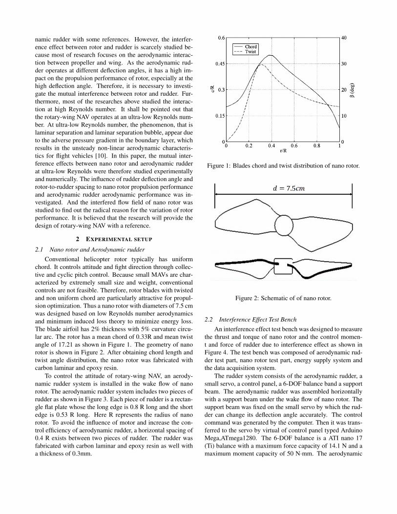
chord. It controls attitude and fight direction through collec-tive and cyclic pitch control. Because small MAVs are char-acterized by extremely small size and weight, conventionalcontrols are not feasible. Therefore, rotor blades with twistedand non uniform chord are particularly attractive for propul-sion optimization. Thus a nano rotor with diameters of 7.5 cmwas designed based on low Reynolds number aerodynamicsand minimum induced loss theory to minimize energy loss.The blade airfoil has 2% thickness with 5% curvature circu-lar arc. The rotor has a mean chord of 0.33R and mean twistangle of 17.21 as shown in Figure 1. The geometry of nanorotor is shown in Figure 2. After obtaining chord length andtwist angle distribution, the nano rotor was fabricated withcarbon laminar and epoxy resin.
To control the attitude of rotary-wing NAV, an aerody-namic rudder system is installed in the wake flow of nanorotor. The aerodynamic rudder system includes two pieces ofrudder as shown in Figure 3. Each piece of rudder is a rectan-gle flat plate whose the long edge is 0.8 R long and the shortedge is 0.53 R long. Here R represents the radius of nanorotor. To avoid the influence of motor and increase the con-trol efficiency of aerodynamic rudder, a horizontal spacing of0.4 R exists between two pieces of rudder. The rudder wasfabricated with carbon laminar and epoxy resin as well witha thickness of 0.3mm.
Figure 1: Blades chord and twist distribution of nano rotor.
Figure 2: Schematic of of nano rotor.
2.2 Interference Effect Test BenchAn interference effect test bench was designed to measure
the thrust and torque of nano rotor and the control momen-t and force of rudder due to interference effect as shown inFigure 4. The test bench was composed of aerodynamic rud-der test part, nano rotor test part, energy supply system andthe data acquisition system.
The rudder system consists of the aerodynamic rudder, asmall servo, a control panel, a 6-DOF balance band a supportbeam. The aerodynamic rudder was assembled horizontallywith a support beam under the wake flow of nano rotor. Thesupport beam was fixed on the small servo by which the rud-der can change its deflection angle accurately. The controlcommand was generated by the computer. Then it was trans-ferred to the servo by virtual of control panel typed ArduinoMega,ATmega1280. The 6-DOF balance is a ATI nano 17(Ti) balance with a maximum force capacity of 14.1 N and amaximum moment capacity of 50 N·mm. The aerodynamic
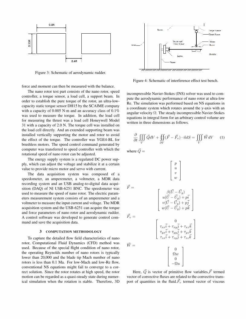
Figure 3: Schematic of aerodynamic rudder.
force and moment can then be measured with the balance.The nano rotor test part consists of the nano rotor, speed
controller, a torque sensor, a load cell, a support beam. Inorder to establish the pure torque of the rotor, an ultra-low-capacity static torque sensor DH15 by the SCAIME companywith a capacity of 0.005 N·m and an accuracy class of 0.1%was used to measure the torque. In addition, the load cellfor measuring the thrust was a load cell Honeywell Model31 with a capacity of 2.0 N. The torque cell was installed onthe load cell directly. And an extended supporting beam wasinstalled vertically supporting the motor and rotor to avoidthe effect of the torque. The controller was YGE4-BL forbrushless motors. The speed control command generated bycomputer was transferred to speed controller with which therotational speed of nano rotor can be adjusted.
The energy supply system is a regulated DC power sup-ply, which can adjust the voltage and stabilize it at a certainvalue to provide micro motor and servo with current.
The data acquisition system was composed of aspeedometer, an amperemeter, a voltmeter, a MDR datarecording system and an USB analog-to-digital data acqui-sition (DAQ) of NI USB-6251 BNC. The speedometer wasused to measure the speed of nano rotor. The electric param-eters measurement system consists of an amperemeter and avoltmeter to measure the input current and voltage. The MDRacquisition system and the USB-6251 can acquire the torqueand force parameters of nano rotor and aerodynamic rudder.A control software was developed to generate control com-mand and save the acquisition data.
3 COMPUTATION METHODOLOGY
To capture the detailed flow field characteristics of nanorotor, Computational Fluid Dynamics (CFD) method wasused. Because of the special flight condition of nano rotor,the operating Reynolds number of nano rotors is typicallylower than 20,000 and the blade tip Mach number of nanorotors is less than 0.1 Ma. For low-Mach and low-Re flow,conventional NS equations might fail to converge to a cor-rect solution. Since the rotor rotates at high speed, the rotormotion can be regarded as a quasi-steady state during numer-ical simulation when the rotation is stable. Therefore, 3D
Figure 4: Schematic of interference effect test bench.
incompressible Navier-Stokes (INS) solver was used to com-pute the aerodynamic performance of nano rotor at ultra-lowRe. The simulation was performed based on NS equations ina coordinate system which rotates around the y-axis with anangular velocity Ω. The steady incompressible Navier-Stokesequations in integral form for an arbitrary control volume arewritten in three dimensions as follows.
∂
∂t
y
V
~QdV +
∂V
(~F − ~Fv) · ~ndS =y
V
~WdV (1)
where ~Q =
puvw
~F =
β(~U − ~Ug)
u(~U − ~Ug) + p~i
v(~U − ~Ug) + p~j
w(~U − ~Ug) + p~k
~Fv =
0
τxx~i+ τxy~j + τxz~k
τyx~i+ τyy~j + τyz~k
τzx~i+ τzy~j + τzz~k
~W =
0Ωw0
−Ωu
Here, ~Q is vector of primitive flow variables,~F termed
vector of convective fluxes are related to the convective trans-port of quantities in the fluid.~Fv termed vector of viscous
fluxes contain the viscous stresses τij , In the formula,~U and~Ug are the velocity component and moving grid velocity com-ponent which can be expressed as
~U = u~i+ v~j + w~k (2)
~Ug = ug~i+ vg~j + wg~k (3)
The equations were solved with finite volume method andRoes flux scheme was employed.
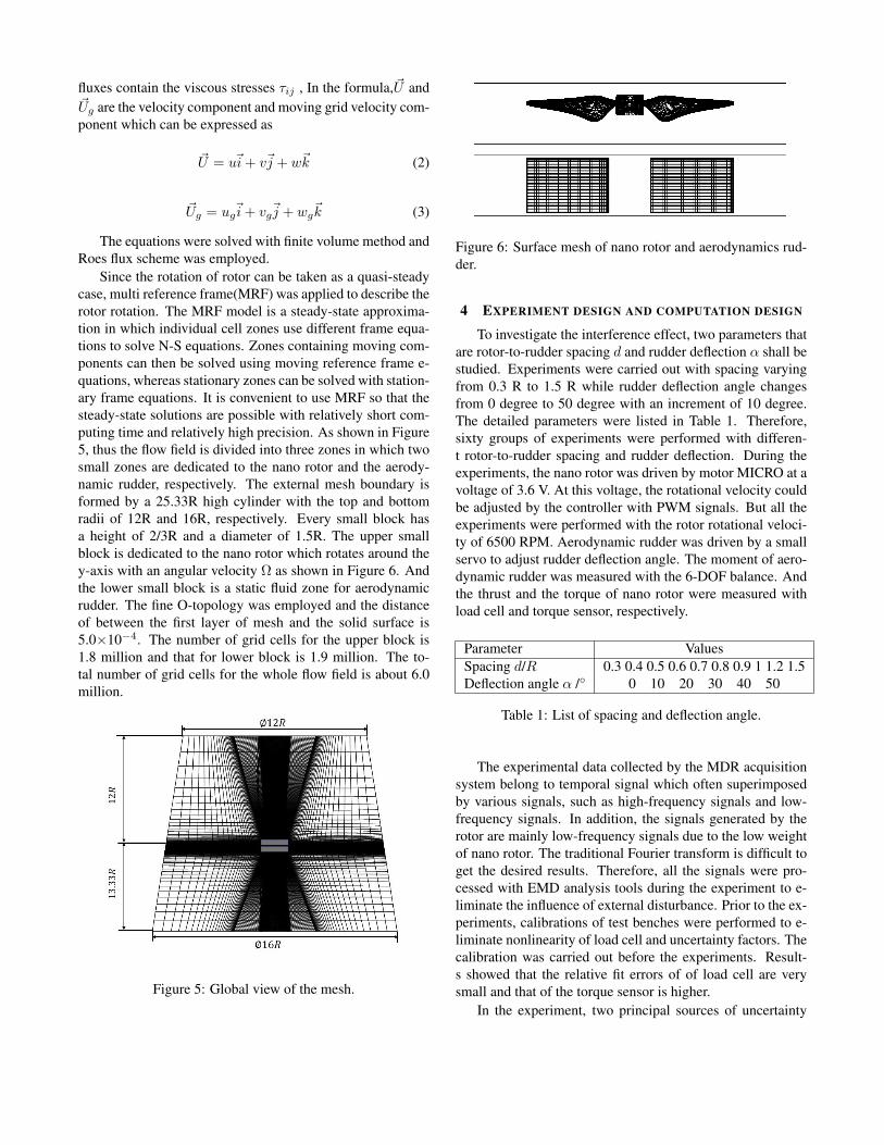
Since the rotation of rotor can be taken as a quasi-steadycase, multi reference frame(MRF) was applied to describe therotor rotation. The MRF model is a steady-state approxima-tion in which individual cell zones use different frame equa-tions to solve N-S equations. Zones containing moving com-ponents can then be solved using moving reference frame e-quations, whereas stationary zones can be solved with station-ary frame equations. It is convenient to use MRF so that thesteady-state solutions are possible with relatively short com-puting time and relatively high precision. As shown in Figure5, thus the flow field is divided into three zones in which twosmall zones are dedicated to the nano rotor and the aerody-namic rudder, respectively. The external mesh boundary isformed by a 25.33R high cylinder with the top and bottomradii of 12R and 16R, respectively. Every small block hasa height of 2/3R and a diameter of 1.5R. The upper smallblock is dedicated to the nano rotor which rotates around they-axis with an angular velocity Ω as shown in Figure 6. Andthe lower small block is a static fluid zone for aerodynamicrudder. The fine O-topology was employed and the distanceof between the first layer of mesh and the solid surface is5.0×10−4. The number of grid cells for the upper block is1.8 million and that for lower block is 1.9 million. The to-tal number of grid cells for the whole flow field is about 6.0million.
Figure 5: Global view of the mesh.
Figure 6: Surface mesh of nano rotor and aerodynamics rud-der.
4 EXPERIMENT DESIGN AND COMPUTATION DESIGN
To investigate the interference effect, two parameters thatare rotor-to-rudder spacing d and rudder deflection α shall bestudied. Experiments were carried out with spacing varyingfrom 0.3 R to 1.5 R while rudder deflection angle changesfrom 0 degree to 50 degree with an increment of 10 degree.The detailed parameters were listed in Table 1. Therefore,sixty groups of experiments were performed with differen-t rotor-to-rudder spacing and rudder deflection. During theexperiments, the nano rotor was driven by motor MICRO at avoltage of 3.6 V. At this voltage, the rotational velocity couldbe adjusted by the controller with PWM signals. But all theexperiments were performed with the rotor rotational veloci-ty of 6500 RPM. Aerodynamic rudder was driven by a smallservo to adjust rudder deflection angle. The moment of aero-dynamic rudder was measured with the 6-DOF balance. Andthe thrust and the torque of nano rotor were measured withload cell and torque sensor, respectively.
Parameter ValuesSpacing d/R 0.3 0.4 0.5 0.6 0.7 0.8 0.9 1 1.2 1.5Deflection angle α / 0 10 20 30 40 50
Table 1: List of spacing and deflection angle.
The experimental data collected by the MDR acquisitionsystem belong to temporal signal which often superimposedby various signals, such as high-frequency signals and low-frequency signals. In addition, the signals generated by therotor are mainly low-frequency signals due to the low weightof nano rotor. The traditional Fourier transform is difficult toget the desired results. Therefore, all the signals were pro-cessed with EMD analysis tools during the experiment to e-liminate the influence of external disturbance. Prior to the ex-periments, calibrations of test benches were performed to e-liminate nonlinearity of load cell and uncertainty factors. Thecalibration was carried out before the experiments. Result-s showed that the relative fit errors of of load cell are verysmall and that of the torque sensor is higher.
In the experiment, two principal sources of uncertainty
are contained. One is the bias errors inherent in the measure-ment devices with regard to offset and drift, and the otheris the precision error. The precision error of measurementwas calculated using the Kline-McClintock method for errorpropagation. All of the results have a confidence of 95% inexperiments.
The computation was performed to observe the detailedflow field of nano rotors to find inherent reason of the vari-ation of rotor performance and rudder performance inducedby the mutual interference between the nano rotor and theaerodynamic rudder. Simulations were carried out at the ro-tational velocity of 6500 RPM for the nano rotor. And therotor-to-rudder spacing is 0.5R while the deflection angle ofaerodynamic rudder is 30 degree. The flow field of nano ro-tor without aerodynamic rudder was also simulated as a ref-erence. A short cylinder with diameter of 10 mm was addedat the center of rotor to take into account the influence of mo-tor. The computations were performed on HP station with 40CPU and 64GB memory for one weeks.
5 RESULTS AND DISCUSSION
5.1 Aerodynamic performance of aerodynamic rudder un-der interference
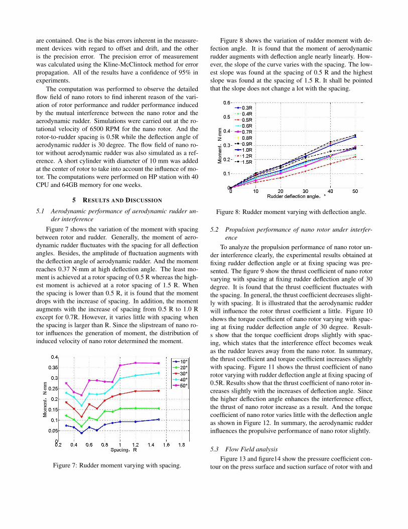
Figure 7 shows the variation of the moment with spacingbetween rotor and rudder. Generally, the moment of aero-dynamic rudder fluctuates with the spacing for all deflectionangles. Besides, the amplitude of fluctuation augments withthe deflection angle of aerodynamic rudder. And the momentreaches 0.37 N·mm at high deflection angle. The least mo-ment is achieved at a rotor spacing of 0.5 R whereas the high-est moment is achieved at a rotor spacing of 1.5 R. Whenthe spacing is lower than 0.5 R, it is found that the momentdrops with the increase of spacing. In addition, the momentaugments with the increase of spacing from 0.5 R to 1.0 Rexcept for 0.7R. However, it varies little with spacing whenthe spacing is larger than R. Since the slipstream of nano ro-tor influences the generation of moment, the distribution ofinduced velocity of nano rotor determined the moment.
Figure 7: Rudder moment varying with spacing.
Figure 8 shows the variation of rudder moment with de-fection angle. It is found that the moment of aerodynamicrudder augments with deflection angle nearly linearly. How-ever, the slope of the curve varies with the spacing. The low-est slope was found at the spacing of 0.5 R and the highestslope was found at the spacing of 1.5 R. It shall be pointedthat the slope does not change a lot with the spacing.
Figure 8: Rudder moment varying with deflection angle.
5.2 Propulsion performance of nano rotor under interfer-ence
To analyze the propulsion performance of nano rotor un-der interference clearly, the experimental results obtained atfixing rudder deflection angle or at fixing spacing was pre-sented. The figure 9 show the thrust coefficient of nano rotorvarying with spacing at fixing rudder deflection angle of 30degree. It is found that the thrust coefficient fluctuates withthe spacing. In general, the thrust coefficient decreases slight-ly with spacing. It is illustrated that the aerodynamic rudderwill influence the rotor thrust coefficient a little. Figure 10shows the torque coefficient of nano rotor varying with spac-ing at fixing rudder deflection angle of 30 degree. Result-s show that the torque coefficient drops slightly with spac-ing, which states that the interference effect becomes weakas the rudder leaves away from the nano rotor. In summary,the thrust coefficient and torque coefficient increases slightlywith spacing. Figure 11 shows the thrust coefficient of nanorotor varying with rudder deflection angle at fixing spacing of0.5R. Results show that the thrust coefficient of nano rotor in-creases slightly with the increases of deflection angle. Sincethe higher deflection angle enhances the interference effect,the thrust of nano rotor increase as a result. And the torquecoefficient of nano rotor varies little with the deflection angleas shown in Figure 12. In summary, the aerodynamic rudderinfluences the propulsive performance of nano rotor slightly.
5.3 Flow Field analysisFigure 13 and figure14 show the pressure coefficient con-
tour on the press surface and suction surface of rotor with and
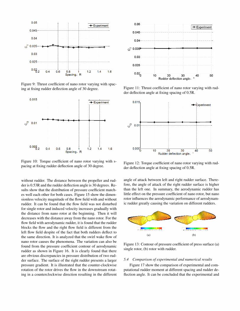
Figure 9: Thrust coefficient of nano rotor varying with spac-ing at fixing rudder deflection angle of 30 degree.
Figure 10: Torque coefficient of nano rotor varying with s-pacing at fixing rudder deflection angle of 30 degree.
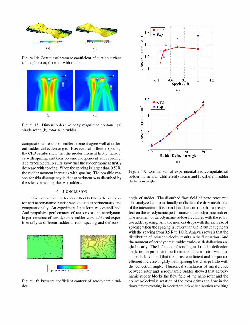
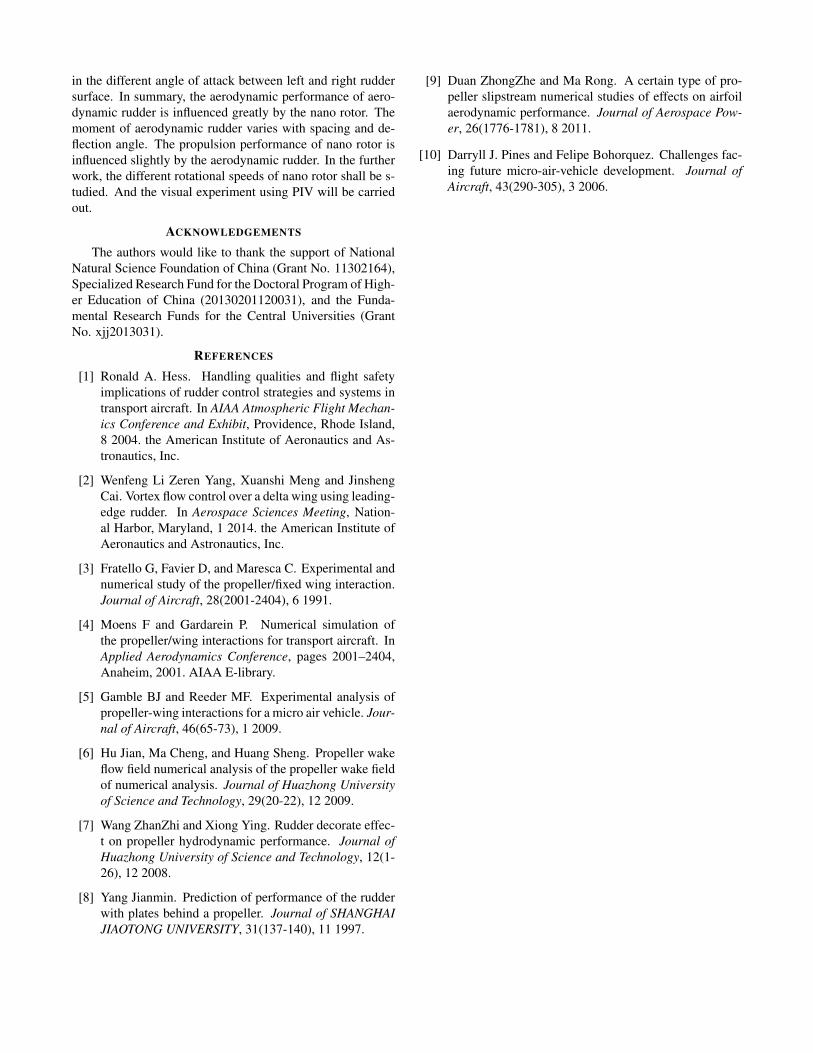
without rudder. The distance between the propeller and rud-der is 0.53R and the rudder deflection angle is 30 degrees. Re-sults show that the distribution of pressure coefficient match-es well each other for both cases. Figure 15 show the dimen-sionless velocity magnitude of the flow field with and withoutrudder. It can be found that the flow field was not disturbedfor single rotor and induced velocity increases gradually withthe distance from nano rotor at the beginning. Then it willdecreases with the distance away from the nano rotor. For theflow field with aerodynamic rudder, it is found that the rudderblocks the flow and the right flow field is different from theleft flow field despite of the fact that both rudders deflect tothe same direction. It is analyzed that the swirl wake flow ofnano rotor causes the phenomena. The variation can also befound from the pressure coefficient contour of aerodynamicrudder as shown in Figure 16. It is clearly found that thereare obvious discrepancies in pressure distribution of two rud-der surface. The surface of the right rudder presents a largerpressure gradient. It is illustrated that the counter-clockwiserotation of the rotor drives the flow in the downstream rotat-ing in a counterclockwise direction resulting in the different
Figure 11: Thrust coefficient of nano rotor varying with rud-der deflection angle at fixing spacing of 0.5R.
Figure 12: Torque coefficient of nano rotor varying with rud-der deflection angle at fixing spacing of 0.5R.
angle of attack between left and right rudder surface. There-fore, the angle of attack of the right rudder surface is higherthan the left one. In summary, the aerodynamic rudder haslittle effect on the pressure coefficient of nano rotor, but nanorotor influences the aerodynamic performance of aerodynam-ic rudder greatly causing the variation on different rudders.
(a) (b)
Figure 13: Contour of pressure coefficient of press surface (a)single rotor, (b) rotor with rudder.
5.4 Comparison of experimental and numerical resultsFigure 17 show the comparison of experimental and com-
putational rudder moment at different spacing and rudder de-flection angle. It can be concluded that the experimental and
(a) (b)
Figure 14: Contour of pressure coefficient of suction surface(a) single rotor, (b) rotor with rudder.
(a) (b)
Figure 15: Dimensionless velocity magnitude contour: (a)single rotor, (b) rotor with rudder.
computational results of rudder moment agree well at differ-ent rudder deflection angle. However, at different spacing,the CFD results show that the rudder moment firstly increas-es with spacing and then become independent with spacing.The experimental results show that the rudder moment firstlydecrease with spacing. When the spacing is larger than 0.53R,the rudder moment increases with spacing. The possible rea-son for this discrepancy is that experiment was disturbed bythe stick connecting the two rudders.
6 CONCLUSION
In this paper, the interference effect between the nano ro-tor and aerodynamic rudder was studied experimentally andcomputationally. An experimental platform was established.And propulsive performance of nano rotor and aerodynam-ic performance of aerodynamic rudder were achieved exper-imentally at different rudder-to-rotor spacing and deflection
Figure 16: Pressure coefficient contour of aerodynamic rud-der.
(a)
(b)
Figure 17: Comparison of experimental and computationalrudder moment at (a)different spacing and (b)different rudderdeflection angle.
angle of rudder. The disturbed flow field of nano rotor wasalso analyzed computationally to disclose the flow mechanicsof the interaction. It is found that the nano rotor has a great ef-fect on the aerodynamic performance of aerodynamic rudder.The moment of aerodynamic rudder fluctuates with the rotor-to-rudder spacing. And the moment drops with the increase ofspacing when the spacing is lower than 0.5 R but it augmentswith the spacing from 0.5 R to 1.0 R. Analysis reveals that thedistribution of induced velocity results in the fluctuation. Andthe moment of aerodynamic rudder varies with deflection an-gle linearly. The influence of spacing and rudder deflectionangle to the propulsion performance of nano rotor was alsostudied. It is found that the thrust coefficient and torque co-efficient increase slightly with spacing but change little withthe deflection angle. Numerical simulation of interferencebetween rotor and aerodynamic rudder showed that aerody-namic rudder blocks the flow field of the nano rotor and thecounter-clockwise rotation of the rotor drives the flow in thedownstream rotating in a counterclockwise direction resulting
in the different angle of attack between left and right ruddersurface. In summary, the aerodynamic performance of aero-dynamic rudder is influenced greatly by the nano rotor. Themoment of aerodynamic rudder varies with spacing and de-flection angle. The propulsion performance of nano rotor isinfluenced slightly by the aerodynamic rudder. In the furtherwork, the different rotational speeds of nano rotor shall be s-tudied. And the visual experiment using PIV will be carriedout.
ACKNOWLEDGEMENTS
The authors would like to thank the support of NationalNatural Science Foundation of China (Grant No. 11302164),Specialized Research Fund for the Doctoral Program of High-er Education of China (20130201120031), and the Funda-mental Research Funds for the Central Universities (GrantNo. xjj2013031).
REFERENCES
[1] Ronald A. Hess. Handling qualities and flight safetyimplications of rudder control strategies and systems intransport aircraft. In AIAA Atmospheric Flight Mechan-ics Conference and Exhibit, Providence, Rhode Island,8 2004. the American Institute of Aeronautics and As-tronautics, Inc.
[2] Wenfeng Li Zeren Yang, Xuanshi Meng and JinshengCai. Vortex flow control over a delta wing using leading-edge rudder. In Aerospace Sciences Meeting, Nation-al Harbor, Maryland, 1 2014. the American Institute ofAeronautics and Astronautics, Inc.
[3] Fratello G, Favier D, and Maresca C. Experimental andnumerical study of the propeller/fixed wing interaction.Journal of Aircraft, 28(2001-2404), 6 1991.
[4] Moens F and Gardarein P. Numerical simulation ofthe propeller/wing interactions for transport aircraft. InApplied Aerodynamics Conference, pages 2001–2404,Anaheim, 2001. AIAA E-library.
[5] Gamble BJ and Reeder MF. Experimental analysis ofpropeller-wing interactions for a micro air vehicle. Jour-nal of Aircraft, 46(65-73), 1 2009.
[6] Hu Jian, Ma Cheng, and Huang Sheng. Propeller wakeflow field numerical analysis of the propeller wake fieldof numerical analysis. Journal of Huazhong Universityof Science and Technology, 29(20-22), 12 2009.
[7] Wang ZhanZhi and Xiong Ying. Rudder decorate effec-t on propeller hydrodynamic performance. Journal ofHuazhong University of Science and Technology, 12(1-26), 12 2008.
[8] Yang Jianmin. Prediction of performance of the rudderwith plates behind a propeller. Journal of SHANGHAIJIAOTONG UNIVERSITY, 31(137-140), 11 1997.
[9] Duan ZhongZhe and Ma Rong. A certain type of pro-peller slipstream numerical studies of effects on airfoilaerodynamic performance. Journal of Aerospace Pow-er, 26(1776-1781), 8 2011.
[10] Darryll J. Pines and Felipe Bohorquez. Challenges fac-ing future micro-air-vehicle development. Journal ofAircraft, 43(290-305), 3 2006.