Embed Size (px)
Citation preview
Experimental Investigation and Optimization of Air-Water
SprayImpingement Cooling to Enhance Heat Transfer
Santosh Kumar Nayak #1, Purna Chandra Mishra#2, S. K. S. Parashar*3 # Thermal Research Laboratory, School of Mechanical Engineering, KIIT University
Bhubaneswar- 751024, Odisha, India [email protected]
[email protected] * Nano Sensor Laboratory, School of Applied Sciences, KIIT University
Bhubaneswar- 751024, Odisha, India [email protected]
Abstract—The current research focused with the optimization of the heat flux from the surface of a hot steel test plate by air atomized water spray cooling. The air atomized water spray cooling experimental setup was designed and fabricated at School of Mechanical Engineering KIIT University, Odisha, India to investigate the role of various process parameters to enhance the heat flux from the surface of the heated steal specimen. The dimensions of test specimen used in the experiment were 120 mm X 120 mm, having different thickness of 4 mm, 6 mm and 8 mm. The effect of the process parameters such as thickness of the test plate, nozzle to plate distance, air and water pressure for removal of heat flux were optimized. The optimization of the controlling parameters was carried out by using the response surface method (RSM). A new correlation was developed for optimization of the surface heat flux.
Keyword-Spray cooling, Response surface method, Optimization, Heat flux, Transient temperature
I. INTRODUCTION
Spray cooling is a most effective thermal management technique which is intermittently applied in steel industry, laser technique, microprocessor and electronic chip cooling and as a heat exchanger in power plant. It is one of the most auspicious technologies which have very large heat removal capacity within a very small area. The prime mechanism of heat transfer in spray cooling method is forced convection with tenacious mixing due to droplet impingement. Because of the complex phenomena, phase change and liquid impact in spray impingement cooling, its heat transfer behaviour still more complicated and it is not so easy to enable systematic, practical system design. So the heat removal phenomena and overall understanding of spray cooling is still in its infancy stages. There are several controlling parameters such as air and water pressure, nozzle to target distance; spray cone angle, spray droplet diameter and thickness of plate are responsible for removal of large heat flux from the hot surface.
Heat treatment is one of the strategies to enhance mechanical properties of metal. Assembling of cold-rolled metal strip accommodates skilful control of few related course of action, for example, hot working, cold working and annealing processes which have tendency to impact the internal structure and state-run of the metal strip. In assembling of cool moved strain less steel, the last step includes the cooling process in the consistent annealing line (CAL). This last step essentially influences vitality utilization of the fabricated metal strip [1]. Researchers [2-7] have studied the implementation of the atomization cooling process both numerically and experimentally. This kind of cooling in hot strip mill demands the cooling down of about 3000C/s that is equivalent to the heat transfer level of 4.37MW using a 4 mm dense carbon steel strip [8]. Augusto et al[9] assessed the heat transfer coefficient in spray cooling of plain and enhanced upward-facing surface. This experiment resulted in the fact the surface type did not influence significantly the critical heat flux. Mascarenhas et al [10] investigated the influence of spray quenching for tubes made from metal alloy. They have tested the size and shape of the impact zone of spray and volumetric flux across the area. The findings suggest that the impact zone along the inner surface of the alloy tube is elliptical in nature. Increase in nozzle pressure drop decreases the volumetric flux which again improves the overall effectiveness of cooling. Pereiral et al [11] have studied the single phase heat transfer copper plate. An array of spray or multiple sprays were used. Full cone pressure nozzles with flow variation capability were used with coolant mass flux 0.28-7.2 kg/m2 range. The results suggest that the nozzles and pulverization capacity forward the differences in pressure. Wang et al [12] tried out to find the effect of surface heat and inclination angle in the non-boiling regime using water spray. Using distilled water as coolant for the semi swirled nozzle keeping different inclination angles with sub cooling
e-ISSN : 0975-4024 Santosh Kumar Nayak et al. / International Journal of Engineering and Technology (IJET)
p-ISSN : 2319-8613 Vol 8 No 1 Feb-Mar 2016 379
of 800C. Karwa et al[13] tried to determine thickness of vapor layer, heat flux of wall and wall superheat at Leidenfrost temperature condition. This theory was developed for the impingement area with traverse pressure gradient both for accelerated and stagnant region. The study predicted that Leidenfrost temperature does not depend upon jet velocity at fixed sub cooling. Wendelstorf et al [14] studied about the transfer of heat during the water spray cooling of clean surface using full cone nozzles (Vd=14 m/s, dd=350 lm) within the parameter range of Vs=3-30 Kg/ (m2.s). The stable film boiling regime depicts decreasing HTC with temperature difference. Lee et al [15] reported in their experiment, that 1/Frz2 was an appropriate dimensionless parameter to relate the nozzle height with variations in the impingement liquid jet velocities and heat transfer rates. Andres et al[16] have presented an experimental and numerical investigation on water droplet during a gas stream impingement on a heated surface. Computational simulations were done using a conjugate solution and VOF model and results concluded that the temperature variation was diffusion dominated during the early stages because of the stagnant droplet impact velocity. Eduardo et al [17] carried out spray cooling experiments which investigated the effect of spray cone angle on heat transfer and film thickness by using R134a refrigerant. It was depicted from the results that the nozzle with a small spray cone had a higher slope in the single phase forced convention regime and the steady nucleate boiling regime. Thiagarajan et al [18] tested the spray boiling heat transfer effect using the coolant HFW-7100 on a micro porous copper surface. They found that the sub-saturated spray attains phase change faster than the sub cooled liquid by removing heat with more efficiency. Somasundaram et al [19] conducted a test using commercial nozzle attached to a solenoid valve and the tests were carried out on an insulated copper block. The whole system was controlled by a closed loop feedback control with varying heat flux regimes of single as well as two phases. Finally, they have proposed that full cone nozzles which can spray uniformly at lower flow rates are more suitable for intermittent spray cooling, enhancing the efficiency. Zhang et al [20] in their research studied de-ionizing water to investigate the impact of spray characteristics, microstructure (flat and enhanced) and roughness of surface on heat transfer. Shadowgraph method employed for measurement of droplet parameters showed that with the increase flow rate, droplet size decreases and velocity and droplet density also increases. Jha et al [21] examined the heat transfer phenomenon of air based alumina nano fluid spray impingement on a moving hot steel plate. From this experiment it was found that alumina added nano fluid is more efficient than water. Cheng et al [22] probed the cooling of large heating surface in a condensed space. This study enweaved that a novel rotating atomized nozzle gave the required sprat characteristic. Distribution of local temperature was not uniform on larger heating areas, and it was extends with the expansion of the surface heat flux. The nozzle inclination also plays very crucial role on cooling efficiency and surface heat flux during ultrafast cooling of heated steel plate by air assisted spray impingement [23].
Significant heat transfer is achieved due to the coolant in form of a spray because the liquid fragments and spreads out, covering the maximum surface area. These applications has many advantages and are affected by various factors like air-water pressure combination [24], water flow rate [25], nozzle-tip to object distance [15], initial temperature of the object, material properties of the surface, surface roughness [26], vapour layer thickness, droplet size [27], spray angle etc. [28] developed artificial neural network (ANN) models to predict spray cooling heat flux of free propane sprays.
Since there are various controlling parameters those have influence on removal of surface heat flux, the current article is the optimization of the controlling parameters such as air-water pressure, nozzle to plate distance, and plate thickness on heat transfer efficiency of air assisted water spray cooling technique.
II. EXPERIMENTAL METHOD
A. Experimental setup
The investigation was carried out with the help of a laboratory scale experimental setup designed and fabricated at School of Mechanical Engineering KIIT University, Odisha, India consists of a spray system, heating unit and a data acquisition system for temperature measurement. A reciprocating air compressor was used to supply compressed air to the spray setup for atomization of the water particle. The test specimens used in the investigations were of dimension 120 mm length and 120 mm width and of three different thickness such as 4 mm, 6 mm and 8 mm embedded with four K-type thermocouples at various locations on the bottom surface of the specimen. The heating of the test plate was carried out with the help of an electric heater in open environment. The transient temperature data were recorded by the help of a CHINO data acquisition system and analysis of temperature data can be done through Zaila application software environment. Fig. 1 represents the schematic of the experimental setup.
e-ISSN : 0975-4024 Santosh Kumar Nayak et al. / International Journal of Engineering and Technology (IJET)
p-ISSN : 2319-8613 Vol 8 No 1 Feb-Mar 2016 380
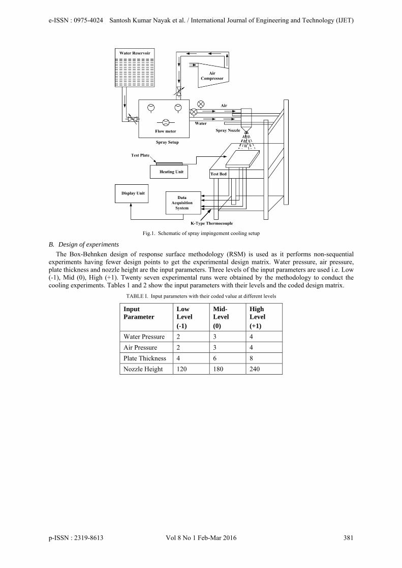
Fig.1. Schematic of spray impingement cooling setup
B. Design of experiments
The Box-Behnken design of response surface methodology (RSM) is used as it performs non-sequential experiments having fewer design points to get the experimental design matrix. Water pressure, air pressure, plate thickness and nozzle height are the input parameters. Three levels of the input parameters are used i.e. Low (-1), Mid (0), High (+1). Twenty seven experimental runs were obtained by the methodology to conduct the cooling experiments. Tables 1 and 2 show the input parameters with their levels and the coded design matrix.
TABLE I. Input parameters with their coded value at different levels
Input Parameter
Low Level (-1)
Mid-Level (0)
High Level (+1)
Water Pressure 2 3 4
Air Pressure 2 3 4
Plate Thickness 4 6 8
Nozzle Height 120 180 240
e-ISSN : 0975-4024 Santosh Kumar Nayak et al. / International Journal of Engineering and Technology (IJET)
p-ISSN : 2319-8613 Vol 8 No 1 Feb-Mar 2016 381
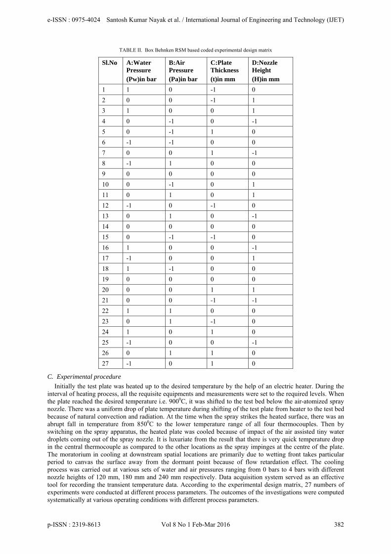
TABLE II. Box Behnken RSM based coded experimental design matrix
Sl.No A:Water Pressure (Pw)in bar
B:Air Pressure (Pa)in bar
C:Plate Thickness (t)in mm
D:Nozzle Height (H)in mm
1 1 0 -1 0
2 0 0 -1 1
3 1 0 0 1
4 0 -1 0 -1
5 0 -1 1 0
6 -1 -1 0 0
7 0 0 1 -1
8 -1 1 0 0
9 0 0 0 0
10 0 -1 0 1
11 0 1 0 1
12 -1 0 -1 0
13 0 1 0 -1
14 0 0 0 0
15 0 -1 -1 0
16 1 0 0 -1
17 -1 0 0 1
18 1 -1 0 0
19 0 0 0 0
20 0 0 1 1
21 0 0 -1 -1
22 1 1 0 0
23 0 1 -1 0
24 1 0 1 0
25 -1 0 0 -1
26 0 1 1 0
27 -1 0 1 0
C. Experimental procedure
Initially the test plate was heated up to the desired temperature by the help of an electric heater. During the interval of heating process, all the requisite equipments and measurements were set to the required levels. When the plate reached the desired temperature i.e. 9000C, it was shifted to the test bed below the air-atomized spray nozzle. There was a uniform drop of plate temperature during shifting of the test plate from heater to the test bed because of natural convection and radiation. At the time when the spray strikes the heated surface, there was an abrupt fall in temperature from 8500C to the lower temperature range of all four thermocouples. Then by switching on the spray apparatus, the heated plate was cooled because of impact of the air assisted tiny water droplets coming out of the spray nozzle. It is luxuriate from the result that there is very quick temperature drop in the central thermocouple as compared to the other locations as the spray impinges at the centre of the plate. The moratorium in cooling at downstream spatial locations are primarily due to wetting front takes particular period to canvas the surface away from the dormant point because of flow retardation effect. The cooling process was carried out at various sets of water and air pressures ranging from 0 bars to 4 bars with different nozzle heights of 120 mm, 180 mm and 240 mm respectively. Data acquisition system served as an effective tool for recording the transient temperature data. According to the experimental design matrix, 27 numbers of experiments were conducted at different process parameters. The outcomes of the investigations were computed systematically at various operating conditions with different process parameters.
e-ISSN : 0975-4024 Santosh Kumar Nayak et al. / International Journal of Engineering and Technology (IJET)
p-ISSN : 2319-8613 Vol 8 No 1 Feb-Mar 2016 382
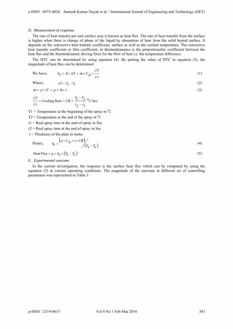
D. Measurement of response
The rate of heat transfer per unit surface area is known as heat flux. The rate of heat transfer from the surface is higher when there is change of phase of the liquid by absorption of heat from the solid heated surface. It depends on the convective heat transfer coefficient, surface as well as the coolant temperature. The convective heat transfer coefficient or film coefficient, in thermodynamics is the proportionality coefficient between the heat flux and the thermodynamic driving force for the flow of heat i.e. the temperature difference.
The HTC can be determined by using equation (4). By putting the value of HTC in equation (5), the magnitude of heat flux can be determined.
We have,
TpCmTAch (1)
Where, cTsTT (2)
tAVm (3)
C/Seco
12
21Rate Cooling
TTCR
T
T1 = Temperature at the beginning of the spray in 0C
T2 = Temperature at the end of the spray in 0C
τ1 = Real spray time at the start of spray in Sec
τ2 = Real spray time at the end of spray in Sec
t = Thickness of the plate in meter
Hence,
cTsT
CRtpCch
(4)
cTsTchq FluxHeat (5)
E. Experimental outcome
In the current investigation, the response is the surface heat flux which can be computed by using the equation (5) at various operating conditions. The magnitude of the outcome at different set of controlling parameters was represented in Table 3.
e-ISSN : 0975-4024 Santosh Kumar Nayak et al. / International Journal of Engineering and Technology (IJET)
p-ISSN : 2319-8613 Vol 8 No 1 Feb-Mar 2016 383
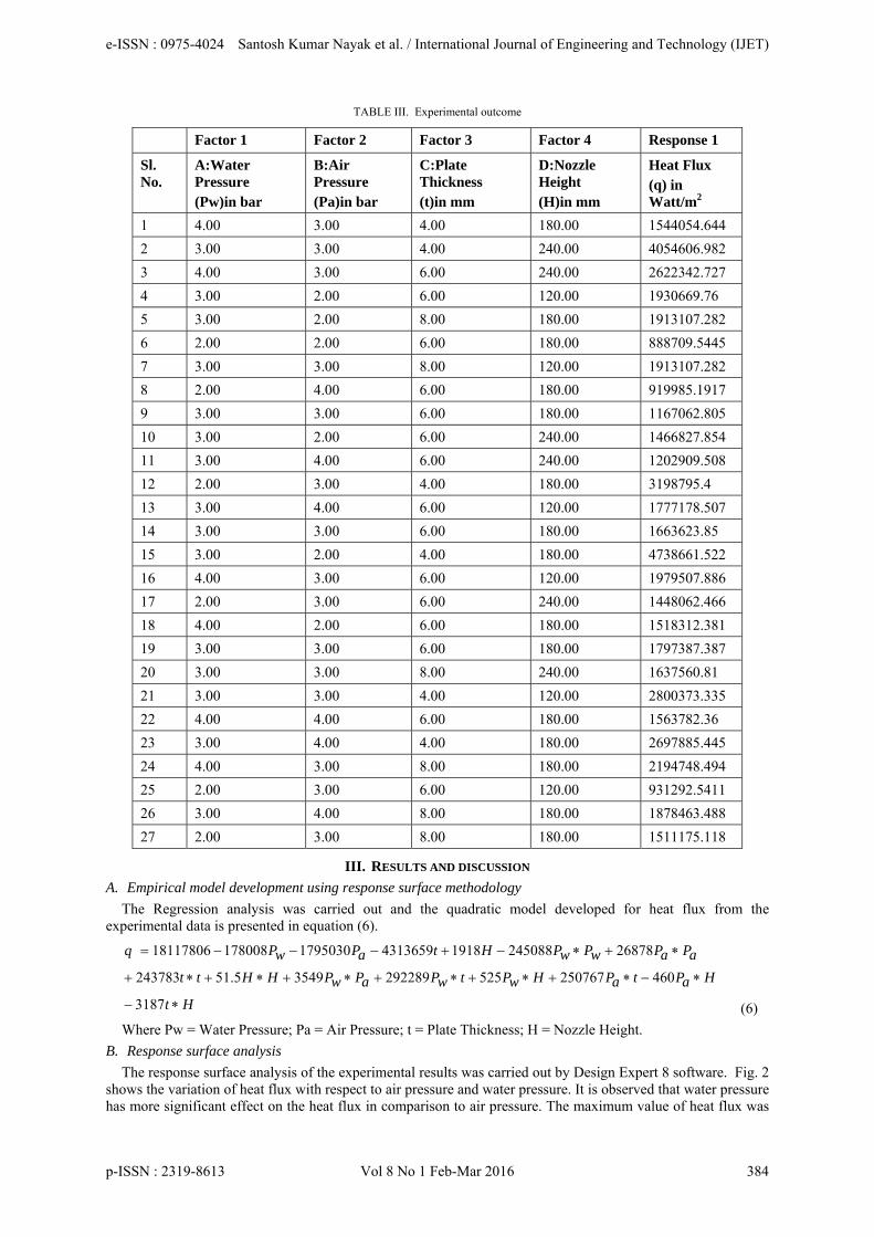
TABLE III. Experimental outcome
Factor 1 Factor 2 Factor 3 Factor 4 Response 1
Sl. No.
A:Water Pressure (Pw)in bar
B:Air Pressure (Pa)in bar
C:Plate Thickness (t)in mm
D:Nozzle Height (H)in mm
Heat Flux (q) in Watt/m2
1 4.00 3.00 4.00 180.00 1544054.644
2 3.00 3.00 4.00 240.00 4054606.982
3 4.00 3.00 6.00 240.00 2622342.727
4 3.00 2.00 6.00 120.00 1930669.76
5 3.00 2.00 8.00 180.00 1913107.282
6 2.00 2.00 6.00 180.00 888709.5445
7 3.00 3.00 8.00 120.00 1913107.282
8 2.00 4.00 6.00 180.00 919985.1917
9 3.00 3.00 6.00 180.00 1167062.805
10 3.00 2.00 6.00 240.00 1466827.854
11 3.00 4.00 6.00 240.00 1202909.508
12 2.00 3.00 4.00 180.00 3198795.4
13 3.00 4.00 6.00 120.00 1777178.507
14 3.00 3.00 6.00 180.00 1663623.85
15 3.00 2.00 4.00 180.00 4738661.522
16 4.00 3.00 6.00 120.00 1979507.886
17 2.00 3.00 6.00 240.00 1448062.466
18 4.00 2.00 6.00 180.00 1518312.381
19 3.00 3.00 6.00 180.00 1797387.387
20 3.00 3.00 8.00 240.00 1637560.81
21 3.00 3.00 4.00 120.00 2800373.335
22 4.00 4.00 6.00 180.00 1563782.36
23 3.00 4.00 4.00 180.00 2697885.445
24 4.00 3.00 8.00 180.00 2194748.494
25 2.00 3.00 6.00 120.00 931292.5411
26 3.00 4.00 8.00 180.00 1878463.488
27 2.00 3.00 8.00 180.00 1511175.118
III. RESULTS AND DISCUSSION
A. Empirical model development using response surface methodology
The Regression analysis was carried out and the quadratic model developed for heat flux from the experimental data is presented in equation (6).
Ht
HaPtaPHwPtwPaPwPHHtt
aPaPwPwPHtaPwPq
3187
460250767525292289354951.5243783
2687824508819184313659179503017800818117806
(6)
Where Pw = Water Pressure; Pa = Air Pressure; t = Plate Thickness; H = Nozzle Height.
B. Response surface analysis
The response surface analysis of the experimental results was carried out by Design Expert 8 software. Fig. 2 shows the variation of heat flux with respect to air pressure and water pressure. It is observed that water pressure has more significant effect on the heat flux in comparison to air pressure. The maximum value of heat flux was
e-ISSN : 0975-4024 Santosh Kumar Nayak et al. / International Journal of Engineering and Technology (IJET)
p-ISSN : 2319-8613 Vol 8 No 1 Feb-Mar 2016 384
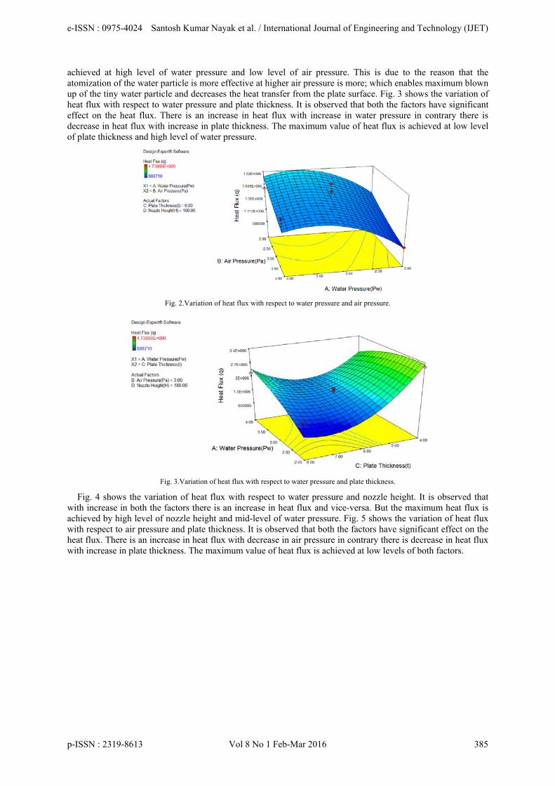
achieved at high level of water pressure and low level of air pressure. This is due to the reason that the atomization of the water particle is more effective at higher air pressure is more; which enables maximum blown up of the tiny water particle and decreases the heat transfer from the plate surface. Fig. 3 shows the variation of heat flux with respect to water pressure and plate thickness. It is observed that both the factors have significant effect on the heat flux. There is an increase in heat flux with increase in water pressure in contrary there is decrease in heat flux with increase in plate thickness. The maximum value of heat flux is achieved at low level of plate thickness and high level of water pressure.
Fig. 2.Variation of heat flux with respect to water pressure and air pressure.
Fig. 3.Variation of heat flux with respect to water pressure and plate thickness.
Fig. 4 shows the variation of heat flux with respect to water pressure and nozzle height. It is observed that with increase in both the factors there is an increase in heat flux and vice-versa. But the maximum heat flux is achieved by high level of nozzle height and mid-level of water pressure. Fig. 5 shows the variation of heat flux with respect to air pressure and plate thickness. It is observed that both the factors have significant effect on the heat flux. There is an increase in heat flux with decrease in air pressure in contrary there is decrease in heat flux with increase in plate thickness. The maximum value of heat flux is achieved at low levels of both factors.
e-ISSN : 0975-4024 Santosh Kumar Nayak et al. / International Journal of Engineering and Technology (IJET)
p-ISSN : 2319-8613 Vol 8 No 1 Feb-Mar 2016 385
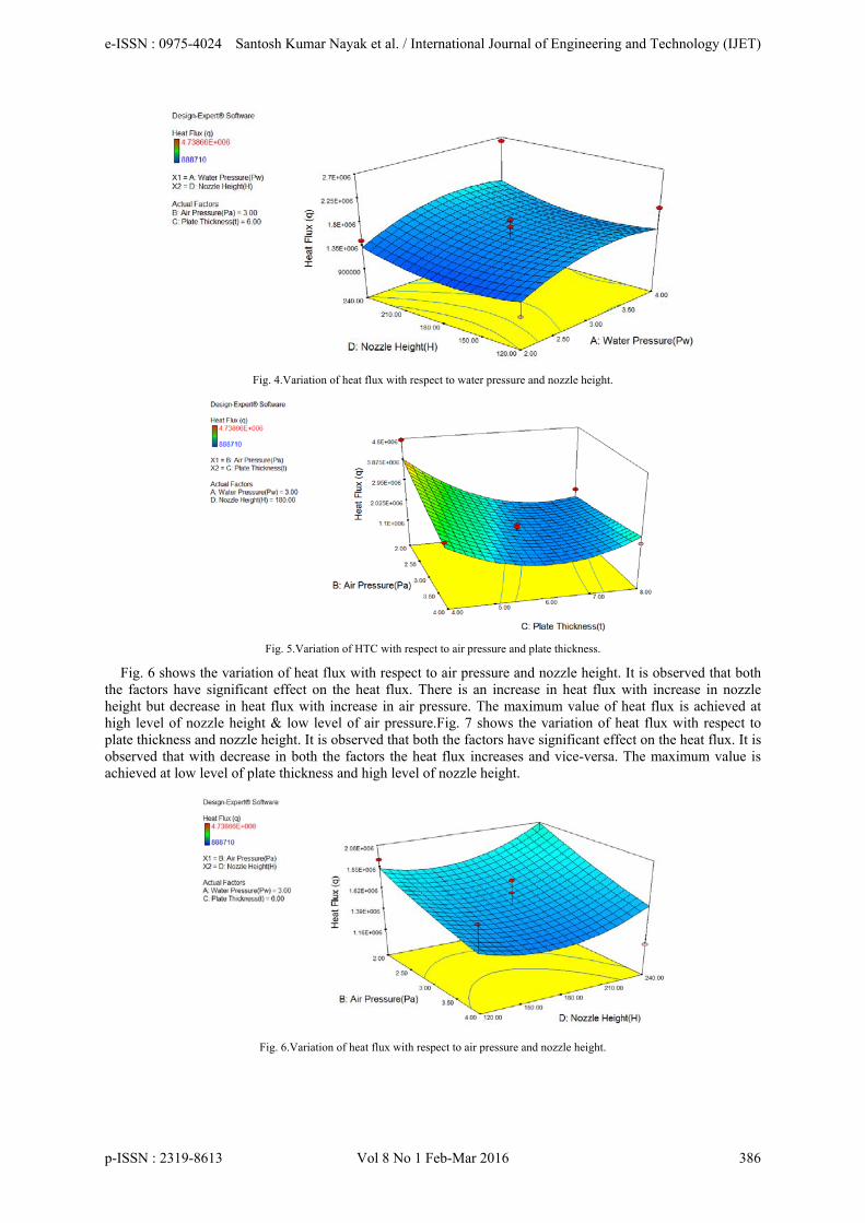
Fig. 4.Variation of heat flux with respect to water pressure and nozzle height.
Fig. 5.Variation of HTC with respect to air pressure and plate thickness.
Fig. 6 shows the variation of heat flux with respect to air pressure and nozzle height. It is observed that both the factors have significant effect on the heat flux. There is an increase in heat flux with increase in nozzle height but decrease in heat flux with increase in air pressure. The maximum value of heat flux is achieved at high level of nozzle height & low level of air pressure.Fig. 7 shows the variation of heat flux with respect to plate thickness and nozzle height. It is observed that both the factors have significant effect on the heat flux. It is observed that with decrease in both the factors the heat flux increases and vice-versa. The maximum value is achieved at low level of plate thickness and high level of nozzle height.
Fig. 6.Variation of heat flux with respect to air pressure and nozzle height.
e-ISSN : 0975-4024 Santosh Kumar Nayak et al. / International Journal of Engineering and Technology (IJET)
p-ISSN : 2319-8613 Vol 8 No 1 Feb-Mar 2016 386
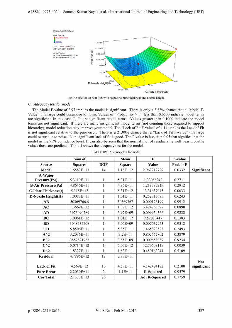
Fig. 7.Variation of heat flux with respect to plate thickness and nozzle height.
C. Adequacy test for model
The Model F-value of 2.97 implies the model is significant. There is only a 3.32% chance that a “Model F-Value” this large could occur due to noise. Values of “Probability > F” less than 0.0500 indicate model terms are significant. In this case C, C2 are significant model terms. Values greater than 0.1000 indicate the model terms are not significant. If there are many insignificant model terms (not counting those required to support hierarchy), model reduction may improve your model. The “Lack of Fit F-value” of 4.14 implies the Lack of Fit is not significant relative to the pure error. There is a 21.00% chance that a “Lack of Fit F-value” this large could occur due to noise. Non-significant lack of fit is good. The P value is less than 0.05 that signifies that the model in the 95% confidence level. It can also be seen that the normal plot of residuals lie well near probable values those are predicted. Table 4 shows the adequacy test for the model.
TABLE IIV. Adequacy test for model
Sum of Mean F p-value
Source Squares DOF Square Value Prob > F
Model 1.6583E+13 14 1.18E+12 2.967717729 0.0332 Significant
A-Water Pressure(Pw) 5.3119E+11 1 5.31E+11 1.33086242 0.2711
B-Air Pressure(Pa) 4.8646E+11 1 4.86E+11 1.218787219 0.2912
C-Plate Thickness(t) 5.315E+12 1 5.31E+12 13.31637045 0.0033
D-Nozzle Height(H) 1.0087E+11 1 1.01E+11 0.252715685 0.6243
AB 50369766.6 1 50369767 0.000126199 0.9912
AC 1.3669E+12 1 1.37E+12 3.424765597 0.0890
AD 3973090789 1 3.97E+09 0.009954366 0.9222
BC 1.0061E+12 1 1.01E+12 2.52083417 0.1383
BD 3048535708 1 3.05E+09 0.007637943 0.9318
CD 5.8506E+11 1 5.85E+11 1.465828523 0.2493
A^2 3.2036E+11 1 3.2E+11 0.802652802 0.3879
B^2 3852821963 1 3.85E+09 0.009653039 0.9234
C^2 5.0714E+12 1 5.07E+12 12.70609119 0.0039
D^2 1.8327E+11 1 1.83E+11 0.459163241 0.5109
Residual 4.7896E+12 12 3.99E+11
Lack of Fit 4.569E+12 10 4.57E+11 4.142474182 0.2100 Not
significant
Pure Error 2.2059E+11 2 1.1E+11 R-Squared 0.9579
Cor Total 2.1373E+13 26 Adj R-Squared 0.7759
e-ISSN : 0975-4024 Santosh Kumar Nayak et al. / International Journal of Engineering and Technology (IJET)
p-ISSN : 2319-8613 Vol 8 No 1 Feb-Mar 2016 387
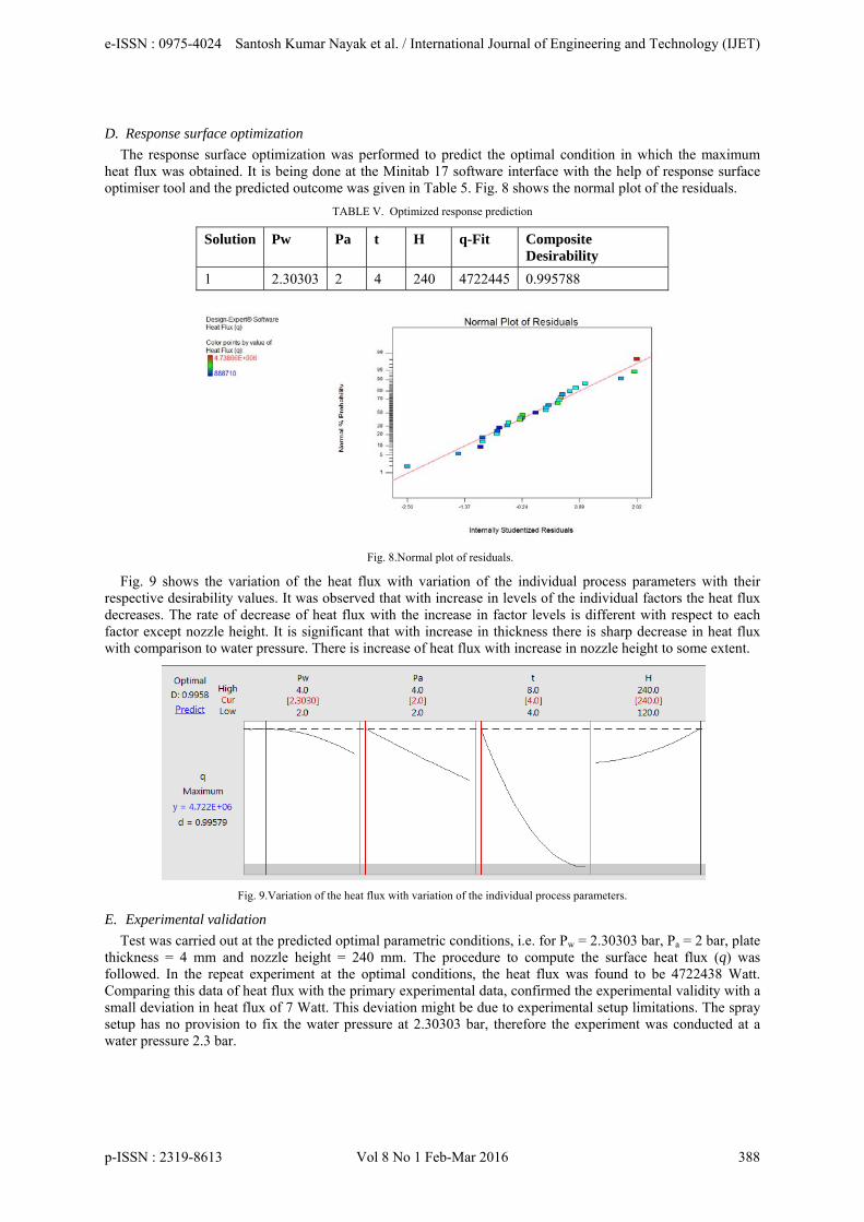
D. Response surface optimization
The response surface optimization was performed to predict the optimal condition in which the maximum heat flux was obtained. It is being done at the Minitab 17 software interface with the help of response surface optimiser tool and the predicted outcome was given in Table 5. Fig. 8 shows the normal plot of the residuals.
TABLE V. Optimized response prediction
Solution Pw Pa t H q-Fit Composite Desirability
1 2.30303 2 4 240 4722445 0.995788
Fig. 8.Normal plot of residuals.
Fig. 9 shows the variation of the heat flux with variation of the individual process parameters with their respective desirability values. It was observed that with increase in levels of the individual factors the heat flux decreases. The rate of decrease of heat flux with the increase in factor levels is different with respect to each factor except nozzle height. It is significant that with increase in thickness there is sharp decrease in heat flux with comparison to water pressure. There is increase of heat flux with increase in nozzle height to some extent.
Fig. 9.Variation of the heat flux with variation of the individual process parameters.
E. Experimental validation
Test was carried out at the predicted optimal parametric conditions, i.e. for Pw = 2.30303 bar, Pa = 2 bar, plate thickness = 4 mm and nozzle height = 240 mm. The procedure to compute the surface heat flux (q) was followed. In the repeat experiment at the optimal conditions, the heat flux was found to be 4722438 Watt. Comparing this data of heat flux with the primary experimental data, confirmed the experimental validity with a small deviation in heat flux of 7 Watt. This deviation might be due to experimental setup limitations. The spray setup has no provision to fix the water pressure at 2.30303 bar, therefore the experiment was conducted at a water pressure 2.3 bar.
e-ISSN : 0975-4024 Santosh Kumar Nayak et al. / International Journal of Engineering and Technology (IJET)
p-ISSN : 2319-8613 Vol 8 No 1 Feb-Mar 2016 388
IV. CONCLUSION
The optimization of the removal of heat flux from a heated steel plate by air assisted spray impingement cooling has been investigated with the predicted optimal conditions. Each of the controlling parameter has significant amount of influence upon the heat flux. From the surface contour, it was very clear that heat flux can be enhanced by maximizing the water pressure and minimizing the air pressure and plate thickness. The optimized value of the heat flux under predicted optimal conditions found to be 4722445 W/m2. This data had good experimental validation.
REFERENCES [1] X. Zhang, Z. Wen, R. Dou, G. Zhou and F. Zhang, “Experimental study of the air-atomized spray cooling of high-temperature metal”,
Applied Therm. Eng., Elsevier, vol.71, pp. 43-55, 2014. [2] J. C. Herman, “Impact of new rolling and cooling technologies on thermo-mechanically processed steels”, Ironmaking & Steelmaking,
Maney Online, vol. 28, pp. 159-163, 2001. [3] J. C. Beale and R. D. Reitz, “Modeling sprays atomization with the Kelvin-Helmholtz/Rayleigh-Taylor hybrid model”, Atomization
and sprays, Begell House, vol. 9, pp. 623-650, 1999. [4] C. X. Bai, H. Rusche and A. D. Gosman, “Modeling of gasoline spray impingement”, Atomization and Sprays, Begell House, vol. 12,
pp. 1-27, 2002. [5] J. C. Landero and A. P. Watkins, “Modeling of steady-state heat transfer in water spray impingement onto a heated wall”,Atomization
and Sprays, Begell House, vol. 18, pp. 1-47, 2008. [6] C. Tropea and I. V. Roisman, “Modeling of spray impact on solid surfaces”, Atomization and sprays, Begell House, vol. 10, pp. 387-
408, 2000. [7] J. Liu, H. Vu, S. S. Yoon, R. A. Jepsen and G. Aguilar, “Splashing phenomena during liquid droplet impact”, Atomization and Sprays,
Begell House, vol. 20, pp. 297-310, 2010. [8] P. Bhattacharya, A.N. Samanta and S. Chakraborty, “Spray evaporative cooling to achieve ultra-fast cooling in runout table”, Int. J. of
Therm. Sci.,Elsevier, vol.48, pp. 1741-1747, 2009. [9] A. G. U. de Souza, and J. R. Barbosa, “Experimental evaluation of spray cooling of R-134a on plain and enhanced surfaces”, Int. J. of
Refrig.,Elsevier, vol.36, pp. 527-533, 2013. [10] N. Mascarenhas and I. Mudawar, “Methodology for predicting spray quenching of thick-walled metal alloy tubes”, Int. J. of Heat and
Mass Transf., Elsevier, vol. 55, pp. 2953-2964, 2012. [11] R. H. Pereira, S. L. Braga and J. A. R. Parise, “Single phase cooling of large surfaces with square arrays of impinging water sprays”,
Applied Therm. Eng., Elsevier, vol. 36, pp. 161-170, 2012. [12] Y. Wang, M. Liu, D. Liu, K. Xu and Y. Chen, “Experimental study on the effects of spray inclination on water spray cooling
performance in non-boiling regime”, Exp. Therm. and Fluid Sci., Elsevier, vol. 34, pp. 933-942, 2010. [13] N. Karwa, T. G. Roisman, P. Stephan and C. Tropea, “A hydrodynamic model for sub cooled liquid jet impingement at the Leidenfrost
condition”, Int. J. of Therm. Sci., Elsevier,vol. 50, pp. 993-1000, 2011. [14] J. Wendelstorf, K.H. Spitzer and R. Wendelstorf, “Spray water cooling heat transfer at high temperatures and liquid mass fluxes”, Int.
J. of Heat and Mass Transf., vol. 51, pp. 4902-4910. [15] P. Lee, H. Choi and S. Lee, “The effect of nozzle height on cooling heat transfer from a hot steel plate by an impinging liquid jet”, ISIJ
Int., vol. 44, pp. 704-709, 2004. [16] A. J. Díaz and A. Ortega, “Investigation of a gas-propelled liquid droplet impinging onto a heated surface”, Int. J. of Heat and Mass
Transf., vol. 67, pp. 1181-1190, 2013. [17] G. E., Martínez, R. Anton, J. C. Ramos and R. Khodabandeh, “Effect of the spray cone angle in the spray cooling with R134a”, Exp.
Therm. and Fluid Sci., vol. 50, pp. 127-138, 2013. [18] S. J. Thiagarajan, S. Narumanchi, R. Yang, “Effect of flow rate and subcooling on spray heat transfer on micro porous copper
surfaces”, Int. J. of Heat and Mass Transf., vol. 69, pp. 493-505, 2014. [19] S. Somasundaram and A. A. O. Tay, “Comparative study of intermittent spray cooling in single and two phase regimes”, Int. J. of
Therm. Sci., vol. 74, pp. 174-182, 2013. [20] Z. Zhang, J. Li and P. X. Jiang, “Experimental investigation of spray cooling on flat and enhanced surfaces”, Applied Therm. Eng., vol.
51, no. 1, pp. 1 S.V., 02-111, 2013. [21] J. M. Jha, S.V. Ravikumar, A. M. Tiara, I. Sarkar, S. K. Pal, S. Chakraborty, “Ultrafast cooling of a hot moving steel plate by using
alumina nanofluid based air atomized spray impingement”, Applied Therm. Eng., vol. 75, pp. 738-747, 2015. [22] W.L. Cheng, W.W. Zhang, L. J. Jiang, S .L. Yang, L. Hu, and , H. Chen, “Experimental investigation of large area spray cooling with
compact chamber in the non-boiling regime”, Applied Therm. Eng., vol. 80, pp. 160-167, 2015. [23] Ravikumar, S.V., Jha, J.M., Mohapatra, S.S., Sinha, A., Pal, S.K., Chakraborty, S., Experimental study of the effect of spray
inclination on ultrafast cooling of a hot steel plate, Heat and Mass Transf., vol. 49, no. 10, pp. 1509-1522, 2013. [24] M. Aamir, L. Qiang, Z. Xun, W. Hong andM. Zubair, “Ultra-fast spray cooling and critical droplet diameter estimation from cooling
rate”, J. of Power and Energy Eng., vol. 2, no. 4, pp. 259-270, 2014. [25] P.C. Mishra, S. K. Nayak, R. Chaini, D. P. Ghosh, B. B. Samantaray,“Effect of controlling parameters on heat transfer during spray
impingement cooling of steel plate”, American J. of Eng. Research, vol. 2, pp. 08-16, 2013. [26] J.D. Bernardin, C. J. Stebbins and I. Mudawar, “Mapping of impact and heat transfer regimes of water drops impinging on a polished
surface”, Int. J. of Heat and Mass Transf., vol. 40, no. 2, pp. 247-267, 1997. [27] P. E. Santangelo, “Characterization of high-pressure water-mist sprays: Experimental analysis of droplet size and dispersion”, Exp.
Therm. and Fluid Sci., vol. 34, pp. 1353-1366, 2010. [28] M. A. Aamir, M. M. Awais and A. P. Watkins, “Applications of artificial neural networks modeling to sprays and spray impingement
heat transfer. Atomization and Sprays”, vol. 12, pp. 359-386, 2002.
e-ISSN : 0975-4024 Santosh Kumar Nayak et al. / International Journal of Engineering and Technology (IJET)
p-ISSN : 2319-8613 Vol 8 No 1 Feb-Mar 2016 389

AUTHOR PROFILE
Santosh Kumar Nayak obtained B.E. in Mechanical Engineering from the Institution of Engineers, Kolkata, India in the year 2007, M.Tech. in Thermal Engineering from S.O.A. University, Bhubaneswar, Odisha, India in the year 2009. He is currently working as an Assistant Professor in the School of Mechanical Engineering, KIIT University, Bhubaneswar, Odisha, India. His research interests are impingement heat transfer, nanofluids, thermal systems design and optimization and computational fluid dynamics.
Purna Chandra Mishra obtained B.E. in Mechanical Engineering from Berhampur University, Odisha, India in the year 2001, M.Tech. and PhD in Mechanical Engineering from Jadavpur University, Kolkata, India in the year 2006 and 2011. He is currently working as a Professor and Associate Dean in the School of Mechanical Engineering, KIIT University, Bhubaneswar, Odisha, India. His research interests are impingement heat transfer, nanofluids, thermal systems design and optimization, combustion engineering, biofuels and computational fluid dynamics.
e-ISSN : 0975-4024 Santosh Kumar Nayak et al. / International Journal of Engineering and Technology (IJET)
p-ISSN : 2319-8613 Vol 8 No 1 Feb-Mar 2016 390


![Experimental and modeling investigation of the … · Experimental and modeling investigation of the effect of air ... tems. The success of this low-NO ... [14] were funded by NASA](https://img.pdfslide.net/doc/110x75/5b76fdb77f8b9a805c8c175e/experimental-and-modeling-investigation-of-the-experimental-and-modeling-investigation.jpg)