Embed Size (px)
Citation preview
EASA Eurocopter Ecureuil / Single Engine Family
Final Report Rev 4 Page 1 of 41
EUROPEAN AVIATION SAFETY AGENCY
EXPERT DEPARTMENT / CERTIFICATION DIRECTORATE
Operational Evaluation Board Report Final Report Revision 4 : 06 08 2012
Manufacturer : EUROCOPTER ECUREUIL / Single Engine Family (AS 350 B, D, B1, B2, BA, BB, B3 & EC 130B4, T2)
European Aviation Safety Agency Postfach 10 12 53 D-50452 Köln, Germany
EASA Eurocopter Ecureuil / Single Engine Family
Final Report Rev 4 Page 2 of 41
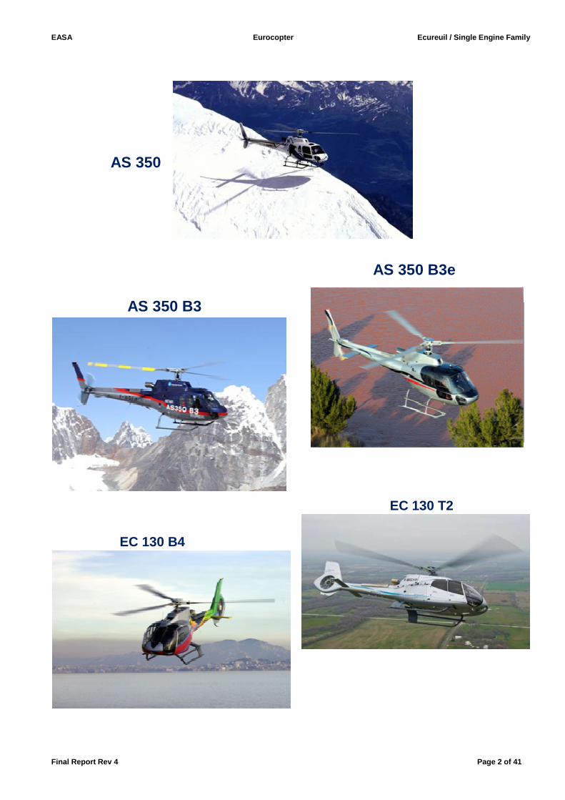
AS 350
AS 350 B3e
AS 350 B3
EC 130 T2
EC 130 B4
EASA Eurocopter Ecureuil / Single Engine Family
Final Report Rev 4 Page 3 of 41
Revision Record
Revision No. Section Date
Final Report All 7-12-2010
Final Report Rev 2 All 7-12-2011
Final Report Rev 3 All 8-02-2012
Final Report Rev 4 All 06-08-2012
EASA Eurocopter Ecureuil / Single Engine Family
Final Report Rev 4 Page 4 of 41
Contents
• Cover ......................................................................................................................... 1
• Helicopters Pictures ................................................................................................... 2
• Revision Record ......................................................................................................... 3
• Contents ..................................................................................................................... 4
• Operation Evaluation Board – OPS-FCL .................................................................... 5
• Eurocopter experts involved in the process ................................................................ 6
• Executive Summary ................................................................................................... 7
• Acronyms ................................................................................................................... 8
1. Purpose and applicability ......................................................................................... 10
2. General Description of AS 350 B, D, B1, B2, BA, BB, B3 & EC 130 B4,T2 ............... 11
3. Helicopters Main Characteristics .............................................................................. 23
4. Operator Differences Requirement (ODR) Tables .................................................... 25
5. Optional specific equipment ..................................................................................... 25
6. Master Differences Requirements ............................................................................ 25
7. Type Rating List and Licence Endorsement List ....................................................... 27
8. Specification for Training .......................................................................................... 27
9. Specification for Testing, Checking & Recent Experience ........................................ 40
10. Specification for Flight Simulation Training Devices ................................................. 40
11. Application of OEB report ......................................................................................... 41
12. Appendices .............................................................................................................. 41
EASA Eurocopter Ecureuil / Single Engine Family
Final Report Rev 4 Page 5 of 41
Operational Evaluation Board – OPS / FCL
Jean-Marc SACAZES EASA – Section Manager Operational Suitability Rotorcraft / Balloons / Airships Experts department- Certification Directorate
Phi lippe COLONGE OEB Member Helicopter Flight Inspector Organisme du Contrôle en Vol (OCV) DGAC - France
EASA Eurocopter Ecureuil / Single Engine Family
Final Report Rev 4 Page 6 of 41
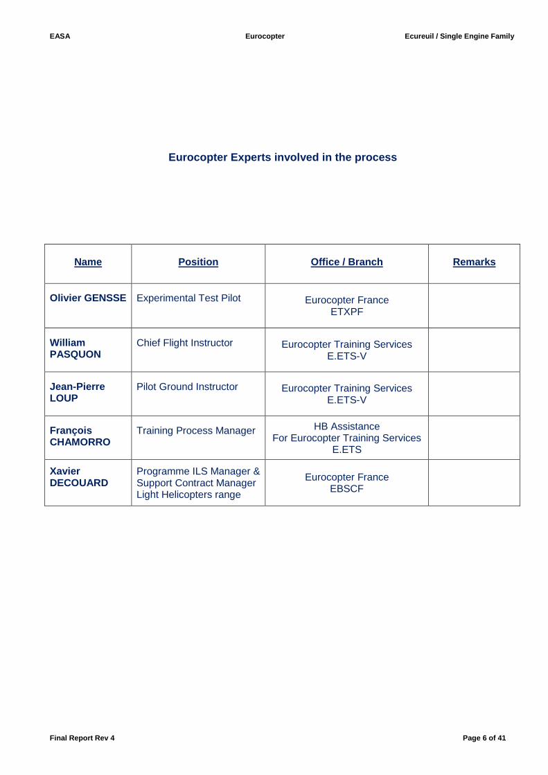
Eurocopter Experts involved in the process
Name
Position
Office / Branch
Remarks
Olivier GENSSE
Experimental Test Pilot
Eurocopter France ETXPF
William PASQUON
Chief Flight Instructor
Eurocopter Training Services E.ETS-V
Jean-Pierre LOUP
Pilot Ground Instructor
Eurocopter Training Services E.ETS-V
François CHAMORRO
Training Process Manager
HB Assistance For Eurocopter Training Services
E.ETS
Xavier DECOUARD
Programme ILS Manager & Support Contract Manager Light Helicopters range
Eurocopter France EBSCF
EASA Eurocopter Ecureuil / Single Engine Family
Final Report Rev 4 Page 7 of 41
Executive Summary
1. Manufacturer Application Eurocopter Manufacturer has made the 12th of April 2010 a first application to EASA, Certification Directorate - Flight Standards to an OEB catch up process for the evaluation of initial Type Ratings and Difference Training courses between all variants / models in both ways for the “Ecureuil / Single engine family” including AS 350 B, D, B1, B2, BA, BB, B3, and B3 Arriel 2B1. In addition Eurocopter has requested to evaluate the EC 130B4 in order to consider this helicopter as a variant included in the Ecureuil / Single engine family. The first OEB final report has been published on EASA Website the 7th of December 2010 In February 2011 Eurocopter applied to evaluate AS 350B3e helicopter in order to consider the B3e as an evolution of the AS 350 B3 Arriel 2B1 and to add this aircraft in the “Ecureuil / Single engine family”.
Then in March 2012 EASA received a new application from Eurocopter for the evaluation the EC 130T2 helicopter in order to consider the EC 130 T2 as an evolution of the EC 130 B4 and to add this aircraft in the “Ecureuil / Single engine family ”.
This final report Rev. 4 supersedes the ‘Ecureuil / Single engine family” previous reports.
2. OEB recommendations The OEB recommends for approval by NAAs:
• Update Type Rating List & Licence Endorsement List • Pilot Initial & Additional Type Rating Training minimum syllabus • Difference Training minimum syllabus • Familiarisation Training • Specifications for particular emphasis during training
3. Procedures, requirements and associated AMC refe rences The EASA Section Manager Operational Suitability Rotorcraft / Balloons / Airships “Jean-Marc Sacazes” qualified on number of AS 350 variants / models, and DGAC / France OCV Flight inspector “Philippe Colonge” qualified and current on most AS 350 variants and Eurocopter Helicopter experts have participated actively to this evaluation (Refer to the list page 6). EASA representatives have conducted this CU OEB in accordance with JAR-OPS 3, Part-FCL and JAR-FSTD H requirements. This evaluation was based on the JOEB Handbook and Common procedures Document (CPD) and the processes detailed in the JAA Administrative and Guidance Material. Note on references and reference texts: Where references are made to requirements and where extracts of reference texts are provided, these are at the amendment state at the date of publication of the report. Readers should take note that it is impractical to update these references to take account of subsequent amendments to the source documents. François FABRE EASA – Deputy Head of Expert Department Certification Directorate
EASA Eurocopter Ecureuil / Single Engine Family
Final Report Rev 4 Page 8 of 41
Acronyms
General AMC Acceptable Means of Compliance AOC Air Operator Certificate ASU Ancillary System Unit ATPL Airline Transport Pilot Licence ATO Approved Training Organisation ATR Additional Type Rating CPD Common Procedures Document (for FAA-TCCA-FAA) CPL Commercial Pilot Licence CWP Caution and Warning Panel DC Direct Current (electrical) DECU Digital Engine Control Unit DGAC Direction Générale de l’Aviation Civile (French Civil Aviation Authority) EASA European Aviation Safety Agency EBCAU Engine Back-Up Control Ancillary Unit EMB Electrical Master Box EC EUROCOPTER EPU External Power Unit ETS Eurocopter Training Services EU-OPS EU-Commercial Air Transportation (Aeroplane) ETS Eurocopter Training Services FADEC Full Authority Digital Engine Control FLI First Limitation Instrument FTD Flight Training Device FNPT Flight and Navigation and Procedure Trainer FSTD Flight Simulation Training Device FTO Flight Training Organisation GPU Ground Power Unit HIP High Increase Power IEM Interpretative and Explanatory Material IFR Instrument Flight Rules IR Instrument Rating ITR Initial Type Rating JAA Joint Aviation Authorities JAR-FCL 1 Joint Aviation Requirements Flight Crew Licensing (Aeroplane) JAR-FCL 2 Joint Aviation Requirements Flight Crew Licensing (Helicopter) JAR-OPS 3 Joint Aviation Requirements Operations 3 (Commercial Air Transportation) (Helicopter) JOEB Joint Operational Evaluation Board MDR Master Difference Requirements MEL Minimum Equipment List MMEL Master Minimum Equipment List NAAs National Aviation Authorities N/A Not Applicable ODR Operator Differences Requirements OEI One Engine Inoperative OEB Operational Evaluation Board
EASA Eurocopter Ecureuil / Single Engine Family
Final Report Rev 4 Page 9 of 41
PPL (A) Private Pilot Licence (Aeroplane) PPL (H) Private Pilot Licence (Helicopter) RFM Rotorcraft Flight Manual SCU System Control Unit SEP (H) Single Engine Piston (Helicopter) SET (H) Single Engine Turbine (Helicopter) TRI Type Rating Instructor T/R Tail Rotor TRTC Type Rating Training Course TRTO Type Rating Training Organisation VEMD Vehicle and Engine Multi-functions Display VFR Visual Flight Rules VNE Velocity Never Exceed Vy Optimum Climbing Speed Helicopter Model designators along historic evoluti on within EADS group AS Aerospatiale BO Bölkow (MBB / Messerschmidt Bölkow Blohm) BK Bölkow / Kawasaki EC Eurocopter SA Sud Aviation SE Société Nationale de Constructions Aéronautiques du Sud-Est SO Société Nationale de Constructions Aéronautiques du Sud-Ouest
EASA Eurocopter Ecureuil / Single Engine Family
Final Report Rev 4 Page 10 of 41
I. Purpose and applicability Data is being submitted by Eurocopter in support of all Operational Evaluations through catch up OEB process for the complete Ecureuil / Single Engine Family. The operator difference tables (ODR) provided by the manufacturer include a comparison of AS 350 B, D, B1, B2, BA, BB, B3, B3 Arriel 2B1, B3e, EC 130B4 &T2 (See Appendix 3). T2 test have been successfully completed by the OEB team. Both OEB Flight Inspectors have flown with the Eurocopter Flight Test Pilot / TRI on most variants. This Final Report Revision 4 is the result of successives evaluations of variants/models which have been made by analysis, comparison and flights, based on Pilot Initial and Additional Type Rating Training syllabus for the Ecureuil / Single Engine Family, provided by Eurocopter Training Services and ATOs’ already approved by DGAC France and by other NAA’s. This document: � Provides a general description of all Ecureuil / Single Engine Family � Updates the Type Rating List and Licence Endorsement List � Makes recommendations for minimum Pilot training syllabus for all Ecureuil / Single Engine Family :
� initial type rating (ITR) � additional type rating (ATR) � Instrument Rating Extension(IR) � differences training � Recent experience � Training area of special emphasis
AS 350 B, D, B1, B2, BA, BB variants/models are all equipped with hydromechanical governing system, OEB is considering that the design and training differences between to be essentially the same variant. In this report to an easy reading the AS 350 B, D, B1, B2, BA, BB are sometimes named and grouped together under “AS 350 Series”.
Note: Ecureuil / Single Engine Family is listed in the Type Certificate Data Sheet delivered by EASA under Type Certificate Data Sheet EASA.R.008. (See Appendix 1).
EASA Eurocopter Ecureuil / Single Engine Family
Final Report Rev 4 Page 11 of 41
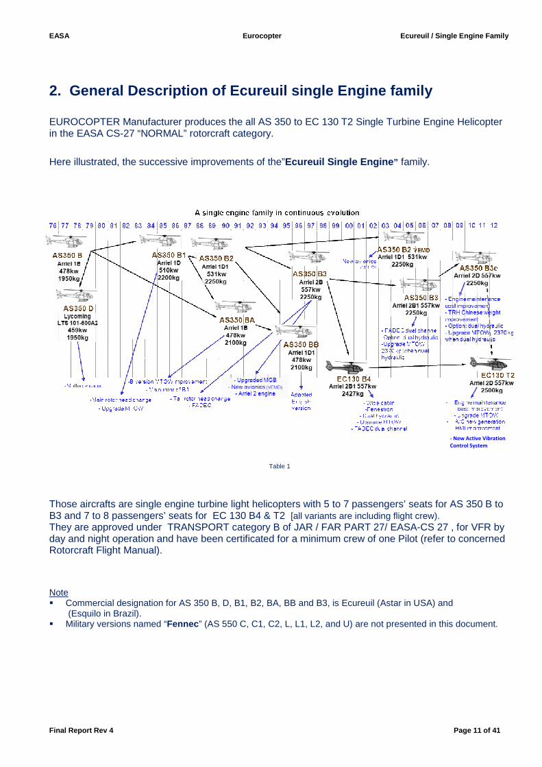
2. General Description of Ecureuil single Engine f amily EUROCOPTER Manufacturer produces the all AS 350 to EC 130 T2 Single Turbine Engine Helicopter in the EASA CS-27 “NORMAL” rotorcraft category. Here illustrated, the successive improvements of the”Ecureuil Single Engine ” family.
Table 1
Those aircrafts are single engine turbine light helicopters with 5 to 7 passengers’ seats for AS 350 B to B3 and 7 to 8 passengers’ seats for EC 130 B4 & T2 [all variants are including flight crew). They are approved under TRANSPORT category B of JAR / FAR PART 27/ EASA-CS 27 , for VFR by day and night operation and have been certificated for a minimum crew of one Pilot (refer to concerned Rotorcraft Flight Manual). Note � Commercial designation for AS 350 B, D, B1, B2, BA, BB and B3, is Ecureuil (Astar in USA) and
(Esquilo in Brazil). � Military versions named “Fennec ” (AS 550 C, C1, C2, L, L1, L2, and U) are not presented in this document.
- New Active Vibration
Control System
EASA Eurocopter Ecureuil / Single Engine Family
Final Report Rev 4 Page 12 of 41
General AS 350 Series ( including AS 350 B, D, B1, B2, BA, BB variants) :
� B powered by a Turboméca Arriel 1B engine (MTOP 478 Kw). � D powered by a Lycoming LTS 101-600A2 engine (MTOP 459 Kw). � B1 powered by a Turboméca Arriel 1D engine (MTOP 510 Kw). � B2 powered by a Turboméca Arriel 1D1 engine (MTOP 531 Kw), � BA powered by a Turboméca Arriel 1B engine (MTOP 478 Kw). � BB powered by a Turboméca Arriel 1D1 engine (MTOP 531 Kw).
All are equipped with: a) An engine governing insured by a N2 and N1 hydro-mechanical system., b) A Manual fuel throttle is installed on a quadrant panel on the cabin floor (Twist grip is an option), c) A Starflex Main Rotor Head three blades design, d) Main rotor composite blades. e) A single hydraulic system, f) A flexible seesaw Tail Rotor type, mainly made of composites,
Recent evolution are equipped with a Vehicle and Engine Multifunction Display (VEMD). Note: Engine Power Check calculation and recording are not available on those VEMD’s.
AS 350 B3:
� Powered by a Turboméca Arriel 2B (MTOP 557 Kw), � Equipped by an electronic Vehicle and Engine Multifunction Display ; a) Engine governing insured by a single channel FADEC b) Equipped with a manual fuel Twist Grip which is located on the collective lever (first aircrafts were
equipped with a manual locking-unlocking device to set the positive range; aircrafts produced after 01-01-2003 are equipped with an electrical automatic unlocking when the red GOV light illuminates on the CWP)
• (c), (d), (e), (f) are identical. AS 350 B3 Ariel 2B1 :
(In production since the AS 350 B3 s/n° 3875 [01-07-20 04]),
� Powered by a Turboméca Arriel 2B1 (MTOP 557 Kw), � Equipped with an electronic Vehicle and Engine Multifunction Display ,
a) Engine governing insured by a dual channel FADEC , b) An emergency Back-up system automatically activated in case of FADEC total failure,
• Automatic variable rotor speed control according to operations conditions (sound level reduction), • Cockpit breakers panels replace the fuses panels (Since the AS 350 B3 s/n° 4193 [01-01-2008]) ,
• (c), (d), (e), (f) are identical.
o A dual hydraulic system for dual-body servo-controls is available in option.
EASA Eurocopter Ecureuil / Single Engine Family
Final Report Rev 4 Page 13 of 41
AS 350 B3e :
� Powered by a Turboméca Arriel 2D (MTOP 557 Kw), equipped with the EDR (Engine Data Recorder), � Equipped with an electronic Vehicle and Engine Multifunction Display ,
a) Engine governing is insured by a dual channel FADEC , b) An emergency Back-up system automatically activated in case of FADEC total failure,
• Automatic variable rotor speed control according to operations conditions (sound level reduction), • Cockpit breakers panels, • Improvement of the Chin Weight efficiency for Tail Rotor suppressing the Load Compensator,
• (c), (d), (e), (f) are identical.
o A dual hydraulic system for dual-body servo-controls is available in option. EC 130 B4:
� Widening of the AS 350 B3 cabin and modernization of the windshield-screen design, � Pilot seat on the left side, e) Dual hydraulic system, for dual-body servo-controls, installed in base, f) Tail Rotor “Fenestron ” design,
And identical to AS 350 B3 2B1 for: � Engine Arriel 2B1 (MTOP 557 Kw), � Equipped with an electronic Vehicle and Engine Multifunction Display ,
• Items (a), (b), (c), (d)
• Automatic variable rotor speed control, • Cockpit breakers panels. EC 130 T2:
� Powered by a Turboméca Arriel 2D (MTOP 710 Kw), equipped with the EDR (Engine Data Recorder), � Equipped with an electronic Vehicle and Engine Multifunction Display , � Main MGB module improved, � New crashworthy fuel tank, � New Active Vibration Control System � New pedestal control panel, � Eurocopter new Air Conditioning concept, � New design of the air intake,
And identical to EC 130 B4 for:
• Wide cabin, • Pilot seat on the left side,
• Items (a), (b), (c), (d), (e), (f)
• Automatic variable rotor speed,
EASA Eurocopter Ecureuil / Single Engine Family
Final Report Rev 4 Page 14 of 41
Structure The fleet’s airframe is composed of Body structure, Front structure and Rear structure and receives various cowlings (MGB, Engine, Tail transmission shaft):
o The body structure forms a Rigid Box Structure, which is the airframe’s strongest structure since it directly supports flight loads and landing loads. The Main Gear Box deck is made with aluminum’s alloy. Baggage’s holds are installed on each side of the body structure. Front and Rear structures are attached on the front and rear bulkheads of the body structure.
o Front structure is composed by a bottom structure, supporting the cabin and is of the cantilever type. Its forms an extension of the body structure. On the EC130 variants, the body and front structure are wider than other Ecureuil variants, the cabin design is modernized and additional transparent front middle panel is installed on the central area of the canopy. For all variants, except on EC 130 T2, below the floor of the cabin are located 2 cabin resonators, reducing the vibration level in the cabin. On EC 130 T2 is installed an Active-Vibration Control System.
o Rear structure provides attachment point for tail boom and encloses the rear baggage compartment and houses the electrical master box and the DECU. Top is the stainless steel engine deck.
o Tail boom supports the tail transmission shaft and receives the horizontal stabilizer, and for AS 350 variants upper and lower fins and a tail cone, with ballast plates mounted inside to correct c.g. position of the empty helicopter. On the EC130 variants, the upper and lower fins and tail cone are replaced by the Fenestron vertical fin, equipped with a stator. On the aft of this vertical fin is located a small compartment for ballast plates mounted inside.
Landing Gear o The landing gear supports the helicopter, protects the airframe on landing and damps out vibration
when the helicopter is on the ground with the rotor spinning. o On AS 350 variants, the landing gear is composed of two tubular steel cross tubes (front and rear)
clamped on the lateral beams of the body structure with rubber devices inside attachments points, and two light alloy skids. Two Shock absorbers are fitted to the front cross tubes, one on each side of the cabin. Top portion is attached to the front bulkhead and the bottom is fitted on the cross tube. On EC 130 variants, the landing gear’s “mustache shape” and three point fitting, with rubber bearings, naturally absorb ground vibrations by oscillating about the center rear fixing point.
o Steel wear-plates are fitted below each skid to avoid wear and tear. o For all aircrafts, another point to note is that the flexibility of the cross tubes, skids attenuates the
helicopter’s vertical deceleration at touchdown. o On AS 350 Series and B3 variants, flexible steel strips are fitted on the aft of each skid to prevent
ground resonance. Seating
Basic configuration: o The cabin features two single seats forward and an assembly of 4 seats backward, on the AS 350
variants. In option, 2 modern high-back energy absorbing forward single-seats can be installed. Also in option a dual passenger seat (limited to 154 kg) can be fitted forward.
o On the EC130 B4 & T2, the cabin features three modern high-back energy absorbing forward single-seats and an assembly of 4 high-back energy absorbing seats backward. In option a club seating configuration/triple passenger seats can be fitted instead of the forward-looking dual passenger seats.
EASA Eurocopter Ecureuil / Single Engine Family
Final Report Rev 4 Page 15 of 41
Main Rotor o All variants of the Ecureuil Family are equipped with a semi-rigid design “Starflex” main rotor head:
neither ball bearings nor lubrication system. The rotor hub is a laminated glass-resin design, and attached to the stainless-steel mast, by a flanged ring and a retaining ring for nuts of Star attachment bolts. The Starflex rotor hub is comparable to a hinged rotor, with elastic return in the flapping and drags directions (the star arms and rubber blocs act as springs).
o A rotor vibration absorber is secured on the flanged ring on the top of the rotor mast. On all AS 350 variants and EC 130 B4 a vibrating weight acts on the excitation loads themselves. On EC 130 T2, the Active-Vibration Control System is composed of 5 accelerometers and 4 vibrating actuators fitted below the cabin, a calculator installed in the tail-boom and a control switch located on the console.
o Rotor speed monitoring follows this principle: A phonic wheel is driven by the main rotor shaft. o Main rotor blades are made of composite materials, the airfoil is the OA 209. Each blade (33.9 kg /
74.74 lb) is equipped with leading edge protections, static and balancing weights devices and 6 tabs. Tail Rotor o The tail rotor of AS 350 series and B3 variants/models is a flexible seesaw type , mainly made of
composites (carbon, fibreglass, Kevlar, etc.) with only a few metal connecting parts.
The basic flexible seesaw type component is a glass-resin roving spar on which the 2 blades are molded. The spar is a thin blade that is flexible in the blade thrust direction and flexible in torsion (on 0.29 R) over its central position for pitch change hinge (thrust control). Actuated by a pitch change bellcrank, like a spider a stationary plate and a rotating plate separated by a ball-bearing, equipped with two pitch change link, mounted free to slide along the rotor shaft. The hinges ball-joints are self-lubricated. The Chin weight efficiency of the AS 350B3e is optimised to supress and the Load Compensator.
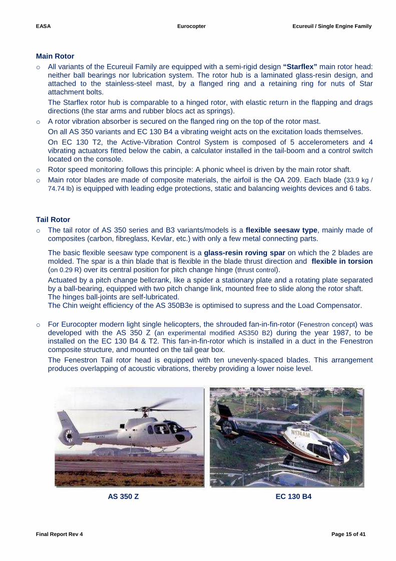
o For Eurocopter modern light single helicopters, the shrouded fan-in-fin-rotor (Fenestron concept) was developed with the AS 350 Z (an experimental modified AS350 B2) during the year 1987, to be installed on the EC 130 B4 & T2. This fan-in-fin-rotor which is installed in a duct in the Fenestron composite structure, and mounted on the tail gear box. The Fenestron Tail rotor head is equipped with ten unevenly-spaced blades. This arrangement produces overlapping of acoustic vibrations, thereby providing a lower noise level.
AS 350 Z EC 130 B4
EASA Eurocopter Ecureuil / Single Engine Family
Final Report Rev 4 Page 16 of 41
Drive System The drive system transmits engine power to the Main Rotor and to the Tail Rotor drive shaft. As the engine is a free turbine type, there is no clutch. The free wheel is integrated in the engine shaft module. The Main Rotor drive train consists of the engine/MGB coupling, the Main Gear Box and the MGB suspension. MGB suspension: On the body structure, the main rotor/MGB assembly is secured to the airframe and to the rotor mast by 4 rigid bars that transmit the lift to the airframe. Below the MGB a flexible suspension is inserted between the MGB and the airframe. The engine to MGB coupling comprises: - A casing secured to the MGB and a flanged connecting coupling secured to the engine, - A gimbal ring joining the casing and flanged coupling, - The drive shaft transmitting the engine torque to the MGB via the input pinion. Drive shaft flexible couplings: the flexible couplings (“Flector” type) bend to absorb the small misalignments between the engine drive shaft and the MGB. The gimbal/flanged coupling connection maintain the MGB/engine distance constant, align the drive shaft with the input pinion, absorb the engine overturning torque.
The Main Gear Box comprises the MGB train and MGB lubrication system inside 3 MGB modules. The rotor brake assembly is secured to the MGB housing and includes a deformable diaphragm to ensure a constant braking torque. The Tail Rotor drive system receives the energy from the engine rear power takeoff and consists in:
- A forward drive shaft, - A rear drive shaft, - The Tail Gear Box.
The shafts are connected to each other, to the engine and to the TGB by 3 flexible couplings. The very long tail rotor drive shaft is supported by 5 ball bearing support assemblies mounted on rubber bushes that damp out the vibrations. The Tail Gear Box is basically an angle reduction gear for AS350 variants/models and angle increase gear for EC130 variants (spiral bevel gear) mounted in and protected by a light alloy casing. TGB is splash lubricated. The oil level is visible through an oil level sight made in Pyrex glass. The TGB is equipped with a drain plug with an electric chip detector. Flight controls Main rotor controls: Below the floor and behind the aft bulkhead of the cabin, the control linkages between the cyclic stick, collective pitch lever and swash-plate consist of rigid rods interconnected by bell-cranks and reversing levers. Each control linkage acts on the swash-plate through a hydraulic servo-actuator that exerts the necessary forces. The standard version of the helicopter is fitted with single-body servo-controls without auto-pilot. Dual body servo-controls and auto-pilot are options for AS 350. For EC 130 variants, dual body servo-controls are part of the basic aircraft configuration. Tail rotor controls: The tail rotor control pedals are interconnected by a rocker arm below the cabin floor so that when one pedal moves forward the other moves backward. Down-line of the rocker arm, the control linkage includes: a control rod, a bellcrank, a flexible-ball-type control and, for AS 350 variants/models at the tail-servo output, a rod actuating the bellcrank of the tail rotor pitch change spider and a load compensator (except for AS 350 B3e, not equipped with Load Compensator). For EC130B4 & T2, the flexible-ball-type control, without tail servo-control, is directly connected from the yaw pedals unit to a small yaw control rod installed at the end of the tail boom and connected to the TGB control lever.
EASA Eurocopter Ecureuil / Single Engine Family
Final Report Rev 4 Page 17 of 41
Rotor brake A slotted cage secured to the MGB housing supports the rotor brake assembly. A mobile slotted cage carrying the brake pads fits inside the first cage. Installed on the cabin ceiling panel for AS 350B3 and EC130 variants, on the cabin floor for others AS 350 variants/models, the rotor brake control lever is equipped with a locking device and a rotor brake start inhibition switch. This switch inhibits the starting electrical power supply when rotor brake is applied.
Engine(s) Except for AS350D with Lycoming engine equipped, all others variants are powered by a free turbine turbo-shaft Arriel engines. The engine is installed at the top of the rear body structure, aft of the MGB, in a fireproof bay.
For AS 350 B, D, B1, B2, BA, BB, the governing system is a two level (NF and NG) hydromechanical type, completed by a mechanical anticipator system, to avoid static droop and response time.
Emergency manual governing is obtained operating the throttle on the quadrant control installed on the cabin floor.
The first AS 350 B3 variant is associated with a single channel FADEC and an emergency manual governing range managed by a twist grip throttle (and a FADEC failure Training mode). For AS 350 B3 Arriel 2B1, AS 350 B3e and EC130 variants, the engine is associated with a dual channel FADEC and an independent automatic emergency governing system which is equipped with the EBCAU test system.
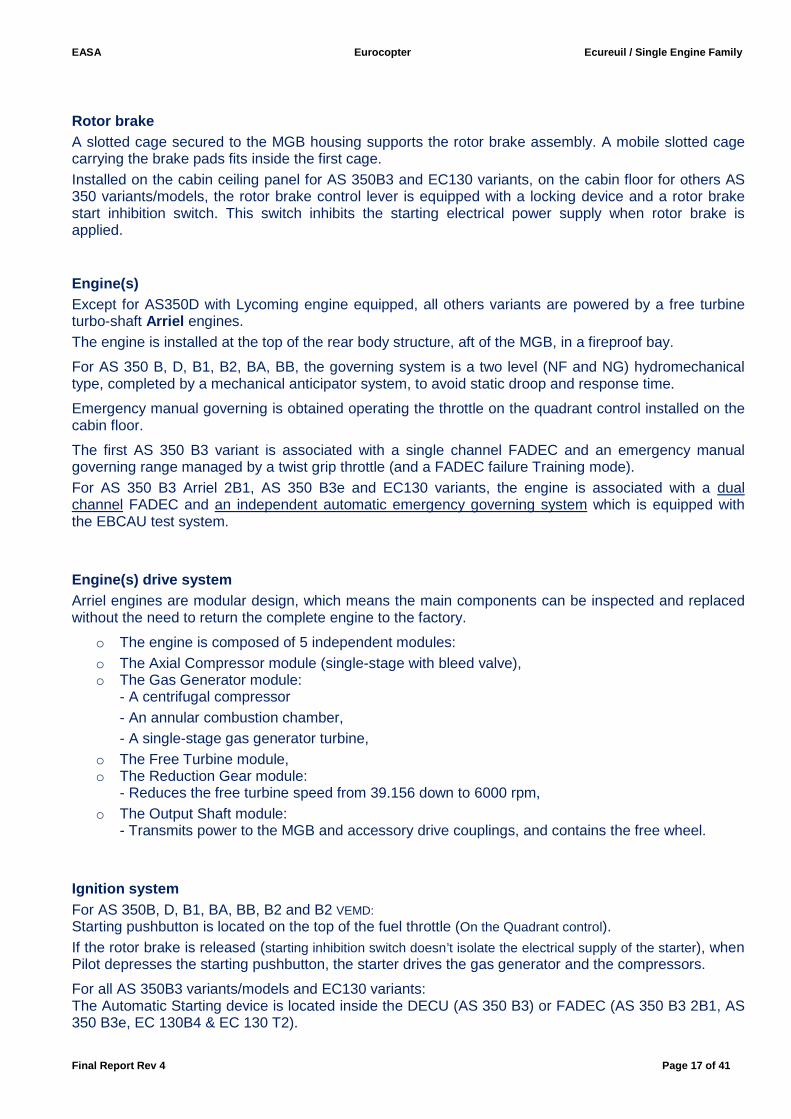
Engine(s) drive system Arriel engines are modular design, which means the main components can be inspected and replaced without the need to return the complete engine to the factory.
o The engine is composed of 5 independent modules: o The Axial Compressor module (single-stage with bleed valve), o The Gas Generator module:
- A centrifugal compressor - An annular combustion chamber, - A single-stage gas generator turbine,
o The Free Turbine module, o The Reduction Gear module:
- Reduces the free turbine speed from 39.156 down to 6000 rpm, o The Output Shaft module:
- Transmits power to the MGB and accessory drive couplings, and contains the free wheel. Ignition system For AS 350B, D, B1, BA, BB, B2 and B2 VEMD: Starting pushbutton is located on the top of the fuel throttle (On the Quadrant control). If the rotor brake is released (starting inhibition switch doesn’t isolate the electrical supply of the starter), when Pilot depresses the starting pushbutton, the starter drives the gas generator and the compressors.
For all AS 350B3 variants/models and EC130 variants: The Automatic Starting device is located inside the DECU (AS 350 B3) or FADEC (AS 350 B3 2B1, AS 350 B3e, EC 130B4 & EC 130 T2).
EASA Eurocopter Ecureuil / Single Engine Family
Final Report Rev 4 Page 18 of 41
Fuel system For AS 350 B3 variants/models and EC 130 variants, the fuel system comprises the aircraft part and the engine part. - The Aircraft fuel system is composed of one spin-mould tank, a supply system, a gravity refuelling
filter and a monitoring system. - The Engine fuel system comprises a LP pump, a fuel filter, a HP pump and a fuel metering unit
which are integrated onto the engine. The fuel metering unit is driven by the FADEC and, in case of FADEC failure, the fuel flow is managed by a back-up system.
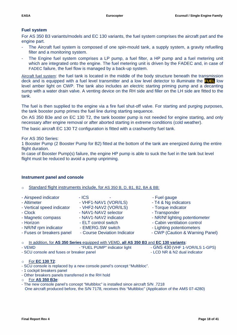
Aircraft fuel system: the fuel tank is located in the middle of the body structure beneath the transmission deck and is equipped with a fuel level transmitter and a low level detector to illuminate the FUEL low level amber light on CWP. The tank also includes an electric starting priming pump and a decanting sump with a water drain valve. A venting device on the RH side and filler on the LH side are fitted to the tank. The fuel is then supplied to the engine via a fire fuel shut-off valve. For starting and purging purposes, the tank booster pump primes the fuel line during starting sequence. On AS 350 B3e and on EC 130 T2, the tank booster pump is not needed for engine starting, and only necessary after engine removal or after aborted starting in extreme conditions (cold weather). The basic aircraft EC 130 T2 configuration is fitted with a crashworthy fuel tank.
For AS 350 Series: 1 Booster Pump (2 Booster Pump for B2) fitted at the bottom of the tank are energized during the entire flight duration. In case of Booster Pump(s) failure, the engine HP pump is able to suck the fuel in the tank but level flight must be reduced to avoid a pump unpriming.
Instrument panel and console o Standard flight instruments include, for AS 350 B, D, B1, B2, BA & BB: - Airspeed indicator - ICS - - Fuel gauge - Altimeter - VHF1-NAV1 (VOR/ILS) - T4 & Ng indicators - Vertical speed indicator - VHF2-NAV2 (VOR/ILS) - Torque indicator - Clock - NAV1-NAV2 selector - Transponder - Magnetic compass - NAV1-NAV2 indicator - NR/Nf lighting potentiometer - Horizon - ELT control switch - Cabin ventilation control - NR/Nf rpm indicator - EMERG.SW switch - Lighting potentiometers - Fuses or breakers panel - Course Deviation Indicator - CWP (Caution & Warning Panel) o In addition, for AS 350 Series equipped with VEMD, all AS 350 B3 and EC 130 variants : - VEMD - “FUEL PUMP” indicator light - GNS 430 (VHF 1-VOR/ILS 1-GPS) - SCU console and fuses or breaker panel - LCD NR & N2 dual indicator
o For EC 130 T2: - SCU console is replaced by a new console panel’s concept “Multibloc”. - 1 cockpit breakers panel - Other breakers panels transferred in the RH hold o For AS 350 B3e : - The new console panel’s concept “Multibloc” is installed since aircraft S/N .7218 One aircraft produced before, the S/N 7178, receives this “Multibloc” (Application of the AMS 07-4280)
EASA Eurocopter Ecureuil / Single Engine Family
Final Report Rev 4 Page 19 of 41
Flight instruments and Ancillary system Based on the theory that when everything is operating correctly there is no need to warn the Pilot, the indicating system generally indicates an abnormal operating situation.
The variants from AS 350 B to B2 are fitted with conventional indicators systems.
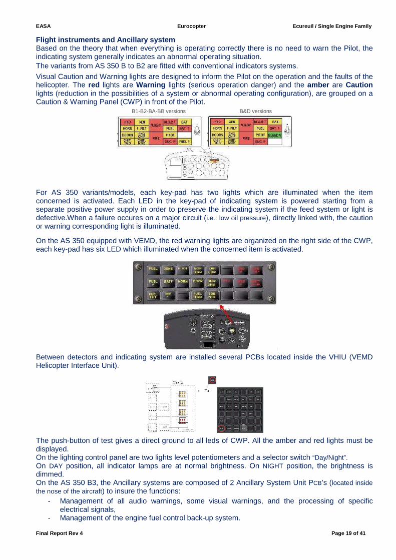
Visual Caution and Warning lights are designed to inform the Pilot on the operation and the faults of the helicopter. The red lights are Warning lights (serious operation danger) and the amber are Caution lights (reduction in the possibilities of a system or abnormal operating configuration), are grouped on a Caution & Warning Panel (CWP) in front of the Pilot.
B1-B2-BA-BB versions B&D versions
For AS 350 variants/models, each key-pad has two lights which are illuminated when the item concerned is activated. Each LED in the key-pad of indicating system is powered starting from a separate positive power supply in order to preserve the indicating system if the feed system or light is defective.When a failure occures on a major circuit (i.e.: low oil pressure), directly linked with, the caution or warning corresponding light is illuminated.
On the AS 350 equipped with VEMD, the red warning lights are organized on the right side of the CWP, each key-pad has six LED which illuminated when the concerned item is activated.
Between detectors and indicating system are installed several PCBs located inside the VHIU (VEMD Helicopter Interface Unit).
The push-button of test gives a direct ground to all leds of CWP. All the amber and red lights must be displayed. On the lighting control panel are two lights level potentiometers and a selector switch “Day/Night”. On DAY position, all indicator lamps are at normal brightness. On NIGHT position, the brightness is dimmed. On the AS 350 B3, the Ancillary systems are composed of 2 Ancillary System Unit PCB’s (located inside the nose of the aircraft) to insure the functions:
- Management of all audio warnings, some visual warnings, and the processing of specific electrical signals,
- Management of the engine fuel control back-up system.
EASA Eurocopter Ecureuil / Single Engine Family
Final Report Rev 4 Page 20 of 41
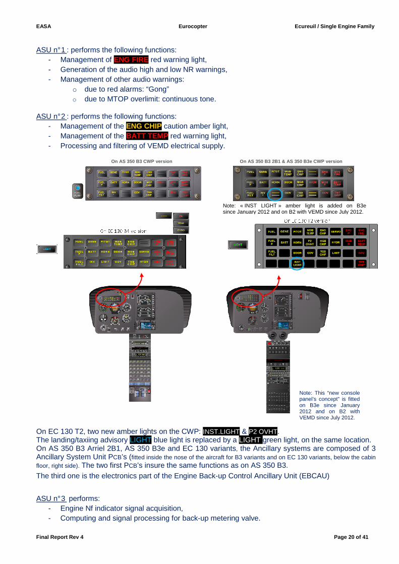
ASU n° 1 : performs the following functions:
- Management of ENG FIRE red warning light, - Generation of the audio high and low NR warnings, - Management of other audio warnings:
o due to red alarms: “Gong” o due to MTOP overlimit: continuous tone.
ASU n° 2 : performs the following functions: - Management of the ENG CHIP caution amber light, - Management of the BATT TEMP red warning light, - Processing and filtering of VEMD electrical supply.
On AS 350 B3 CWP version On AS 350 B3 2B1 & AS 350 B3e CWP version
On EC 130 T2, two new amber lights on the CWP: INST.LIGHT & P2 OVHT. The landing/taxiing advisory LIGHT blue light is replaced by a LIGHT green light, on the same location. On AS 350 B3 Arriel 2B1, AS 350 B3e and EC 130 variants, the Ancillary systems are composed of 3 Ancillary System Unit PCB’s (fitted inside the nose of the aircraft for B3 variants and on EC 130 variants, below the cabin floor, right side). The two first PCB’s insure the same functions as on AS 350 B3. The third one is the electronics part of the Engine Back-up Control Ancillary Unit (EBCAU)
ASU n° 3 performs: - Engine Nf indicator signal acquisition, - Computing and signal processing for back-up metering valve.
Note: This “new console panel’s concept” is fitted on B3e since January 2012 and on B2 with VEMD since July 2012.
P2OVHT
Note: « INST LIGHT » amber light is added on B3e since January 2012 and on B2 with VEMD since July 2012.
EASA Eurocopter Ecureuil / Single Engine Family
Final Report Rev 4 Page 21 of 41
Vehicle & Engine Multifunction Display The VEMD is used in flight mode in normal operation. AS 350Series equipped with VEMD, all AS350B3 variants and EC130 variants are fitted with the LCD dual screen Vehicle & Engine Multifunction Display, to optimize the engine and vehicle monitoring and the mission parameters calculation. Supplied with a dual 28 VDC power supply, protected by fuses or circuit breakers, the VEMD comprises:
- 2 computing modules LANE 1 and LANE 2, - One screen module which comprises two screens and the 10 control pushbuttons.
This mode displays Engine, Vehicle, First Limitation Instrument, Flight report and only for AS 350 B3 variants/models and EC130 variants: Engine Power Check pages.
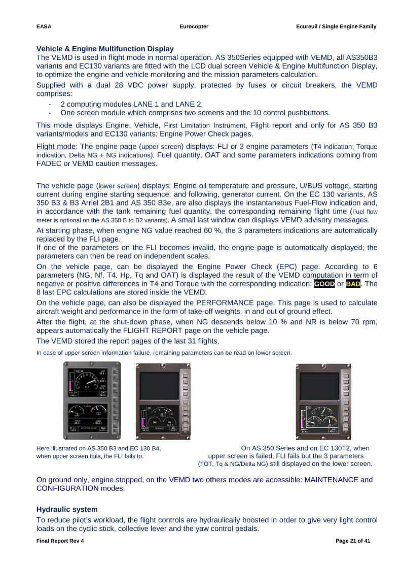
Flight mode: The engine page (upper screen) displays: FLI or 3 engine parameters (T4 indication, Torque indication, Delta NG + NG indications), Fuel quantity, OAT and some parameters indications coming from FADEC or VEMD caution messages.
The vehicle page (lower screen) displays: Engine oil temperature and pressure, U/BUS voltage, starting current during engine starting sequence, and following, generator current. On the EC 130 variants, AS 350 B3 & B3 Arriel 2B1 and AS 350 B3e, are also displays the instantaneous Fuel-Flow indication and, in accordance with the tank remaining fuel quantity, the corresponding remaining flight time (Fuel flow meter is optional on the AS 350 B to B2 variants). A small last window can displays VEMD advisory messages. At starting phase, when engine NG value reached 60 %, the 3 parameters indications are automatically replaced by the FLI page. If one of the parameters on the FLI becomes invalid, the engine page is automatically displayed; the parameters can then be read on independent scales. On the vehicle page, can be displayed the Engine Power Check (EPC) page. According to 6 parameters (NG, Nf, T4, Hp, Tq and OAT) is displayed the result of the VEMD computation in term of negative or positive differences in T4 and Torque with the corresponding indication: GOOD or BAD . The 8 last EPC calculations are stored inside the VEMD. On the vehicle page, can also be displayed the PERFORMANCE page. This page is used to calculate aircraft weight and performance in the form of take-off weights, in and out of ground effect. After the flight, at the shut-down phase, when NG descends below 10 % and NR is below 70 rpm, appears automatically the FLIGHT REPORT page on the vehicle page. The VEMD stored the report pages of the last 31 flights.
In case of upper screen information failure, remaining parameters can be read on lower screen.
Here illustrated on AS 350 B3 and EC 130 B4, On AS 350 Series and on EC 130T2, when when upper screen fails, the FLI fails to. upper screen is failed, FLI fails but the 3 parameters
(TOT, Tq & NG/Delta NG) still displayed on the lower screen.
On ground only, engine stopped, on the VEMD two others modes are accessible: MAINTENANCE and CONFIGURATION modes. Hydraulic system To reduce pilot’s workload, the flight controls are hydraulically boosted in order to give very light control loads on the cyclic stick, collective lever and the yaw control pedals.
EASA Eurocopter Ecureuil / Single Engine Family
Final Report Rev 4 Page 22 of 41
For the whole fleet [except EC130 variants], there are three single-cylinders main rotor servos, one longitudinal and two laterals; and also a single-cylinder tail rotor servo for yaw control. On EC130 variants (optionally on AS350B3 Arriel 2B1 and AS350B3e), there are three dual-cylinder main servos, one longitudinal and two laterals. Hydraulic system controls and monitoring: The hydraulic cut-off switch is a guarded switch (ON-OFF) mounted on the collective lever, except on EC 130 variants. In off position, the hydraulic system is depressurised and the accumulators on the main servo safety units are depressurised simultaneously, but the tail rotor load compensating system retains its assist function. On AS 350 B3 Arriel 2B1 and B3e equipped with Dual Hydraulic system, the hydraulic cut-off switch isolates the tail hydraulic part.
Electrical system The generation and distribution system supplies the electrical network with DC regulated voltage. The network is supplied by: - A starter generator located on the engine accessory gear box, - A 15 A/h battery located in the RH cargo bay on AS 350, and inside the tail-boom on EC130B4, - An optional second battery storage may be installed, - A 28 V external power unit (EPU) plug on the right side (400A max) of the aircraft.
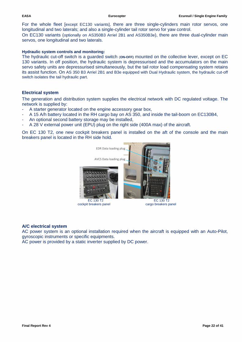
On EC 130 T2, one new cockpit breakers panel is installed on the aft of the console and the main breakers panel is located in the RH side hold.
EC 130 T2 EC 130 T2
cockpit breakers panel cargo breakers panel
A/C electrical system AC power system is an optional installation required when the aircraft is equipped with an Auto-Pilot, gyroscopic instruments or specific equipments. AC power is provided by a static inverter supplied by DC power.
AVCS Data loading plug
EDR Data loading plug
EASA Eurocopter Ecureuil / Single Engine Family
Final Report Rev 4 Page 23 of 41
3. Helicopters main characteristics
3.1 Sum up of main characteristics of Ecureuil “Sin gle engine family”
Ecureuil Single engine family
AS 350 B
AS 350 D
AS 350 B1
AS 350 B2
AS 350 BA
AS 350 BB
AS 350 B3
AS 350 B3 Arriel
2B1
AS 350 B3e
EC 130 B4
EC 130 T2
Dimensions
Fuselage
Length 10.93 m identical identical identical identical identical identical identical identical 10.68 m identical
Width 1.87 m identical identical identical identical identical identical identical identical 2.03 m identical
Height 3.02 m identical identical identical identical identical identical identical identical 3.61 m identical
Main rotor
Diameter
10.69 m identical identical identical identical identical identical identical identical 10.69 m identical
Tail rotor 1.86 m identical identical identical identical identical identical identical identical 1 m identical
Engines Turboméca
Arriel 1B
Lycoming LTS 101-
600A2
Turboméca
Arriel 1D
Turboméca Arriel 1D1
Turboméca
Arriel 1B
Turboméca Arriel 1D1
Turboméca
Arriel 2B
Turboméca Arriel 2B1
Turboméca
Arriel 2D
Turboméca Arriel 2B1
Turboméca
Arriel 2D
Fuel tanks 540 l. identical identical identical identical identical identical identical identical identical identical
Air Speed
Power ON
Absolute VNE
147 kt identical identical identical identical 155 kt identical identical identical identical Identical if normal CG Note*
Power OFF 120 kt identical identical identical identical 125 kt identical identical identical identical Identical
Rotor Speed
Power ON
385 rpm +1/ -5 rpm
identical 390 rpm
+4/ -5 rpm identical identical identical
390 rpm +4/ -5 rpm
375 to 405 rpm
identical identical identical
Autorotation
424 to 320 rpm
identical 430 to 320 rpm
identical identical identical identical 430 to 320 rpm
identical identical identical
Maximum Operating Pressure
Altitude 16000 ft 15000 ft 20000 ft identical 16000 ft identical identical 23000 ft identical identical identical
MTOW with Internal load 1950 Kg identical 2200 Kg 2250 Kg 2100 Kg 2250 Kg identical
Identical
Note (α) Identical
Note (α) 2427 Kg 2500 Kg
MTOW with External load 2100 Kg identical 2450 Kg 2250 Kg 2250 Kg 2500 Kg 2800 Kg identical identical identical 3050 Kg
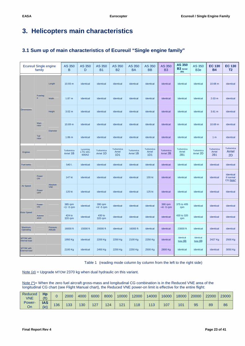
Table 1 (reading mode column by column from the left to the right side)
Note (α) = Upgrade MTOW 2370 kg when dual hydraulic on this variant.
Note (*)= When the zero fuel aircraft gross-mass and longitudinal CG combination is in the Reduced VNE area of the longitudinal CG chart (see Flight Manual chart), the Reduced VNE power-on limit is effective for the entire flight:
Reduced VNE
Power-On
Hp (ft) 0 2000 4000 6000 8000 10000 12000 14000 16000 18000 20000 22000 23000
IAS (kt) 136 133 130 127 124 121 118 113 107 101 95 89 86
EASA Eurocopter Ecureuil / Single Engine Family
Final Report Rev 4 Page 24 of 41
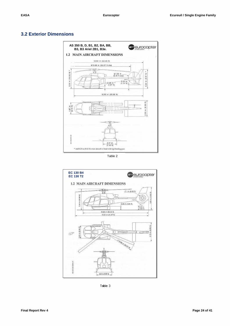
3.2 Exterior Dimensions
AS 350 B, D, B1, B2, BA, BB, B3, B3 Ariel 2B1, B3e.
Table 2
EC 130 B4 EC 130 T2
EASA Eurocopter Ecureuil / Single Engine Family
Final Report Rev 4 Page 25 of 41
4. Operator Difference Requirement (ODR) Tables Operator Difference Requirement tables have been produced by Eurocopter to evaluate the “Ecureuil “ Single engine family on Pilot Initial Training course and difference training in between all variants / models. (See Appendix 3). During the last evaluation of the EC 130T2 the reference aircraft was the EC 130 B4.
5. Optional specific equipment Optional specific equipment tables have been produced also by Eurocopter (See Appendix 3).
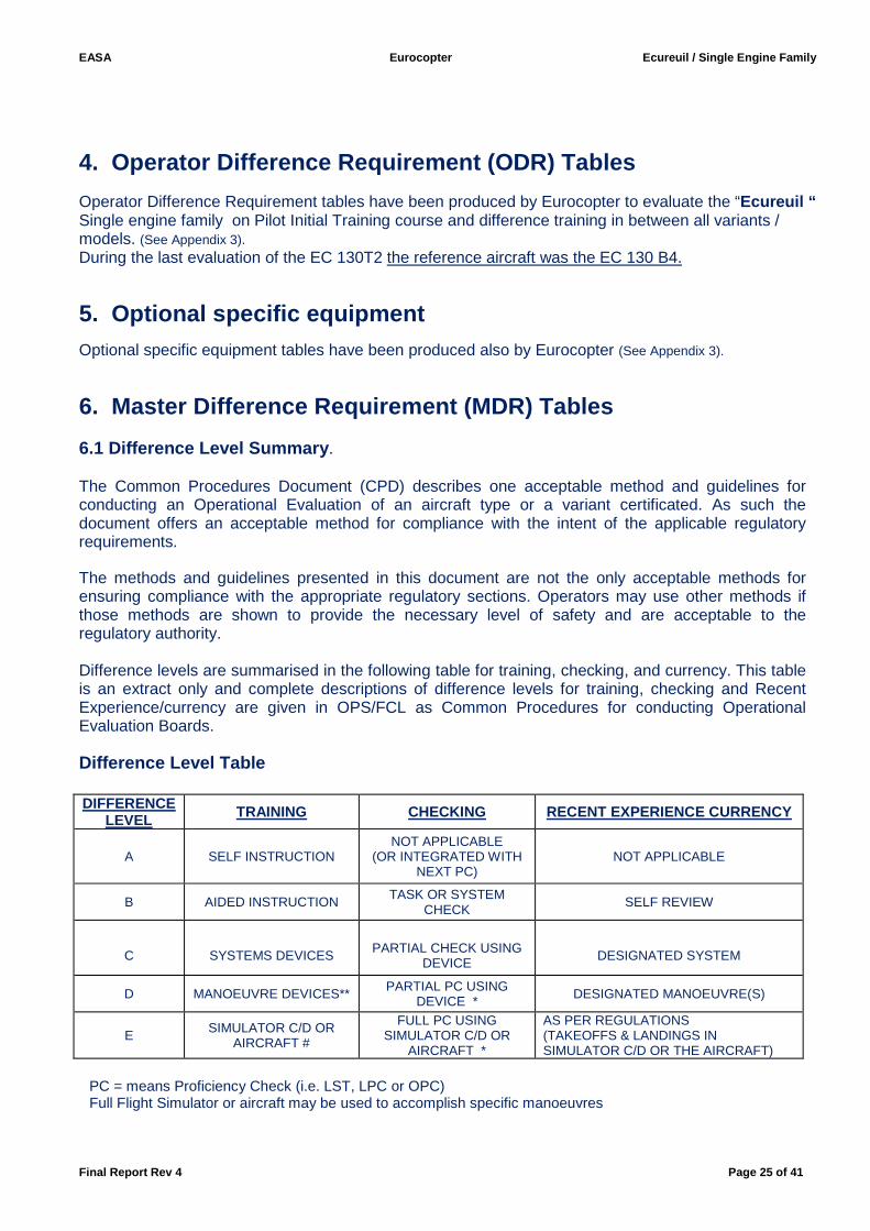
6. Master Difference Requirement (MDR) Tables 6.1 Difference Level Summary . The Common Procedures Document (CPD) describes one acceptable method and guidelines for conducting an Operational Evaluation of an aircraft type or a variant certificated. As such the document offers an acceptable method for compliance with the intent of the applicable regulatory requirements. The methods and guidelines presented in this document are not the only acceptable methods for ensuring compliance with the appropriate regulatory sections. Operators may use other methods if those methods are shown to provide the necessary level of safety and are acceptable to the regulatory authority. Difference levels are summarised in the following table for training, checking, and currency. This table is an extract only and complete descriptions of difference levels for training, checking and Recent Experience/currency are given in OPS/FCL as Common Procedures for conducting Operational Evaluation Boards.
Difference Level Table DIFFERENCE
LEVEL TRAINING CHECKING RECENT EXPERIENCE CURRENCY
A SELF INSTRUCTION NOT APPLICABLE
(OR INTEGRATED WITH NEXT PC)
NOT APPLICABLE
B AIDED INSTRUCTION TASK OR SYSTEM CHECK
SELF REVIEW
C
SYSTEMS DEVICES
PARTIAL CHECK USING
DEVICE
DESIGNATED SYSTEM
D MANOEUVRE DEVICES** PARTIAL PC USING DEVICE * DESIGNATED MANOEUVRE(S)
E SIMULATOR C/D OR AIRCRAFT #
FULL PC USING SIMULATOR C/D OR
AIRCRAFT *
AS PER REGULATIONS (TAKEOFFS & LANDINGS IN SIMULATOR C/D OR THE AIRCRAFT)
PC = means Proficiency Check (i.e. LST, LPC or OPC) Full Flight Simulator or aircraft may be used to accomplish specific manoeuvres
EASA Eurocopter Ecureuil / Single Engine Family
Final Report Rev 4 Page 26 of 41
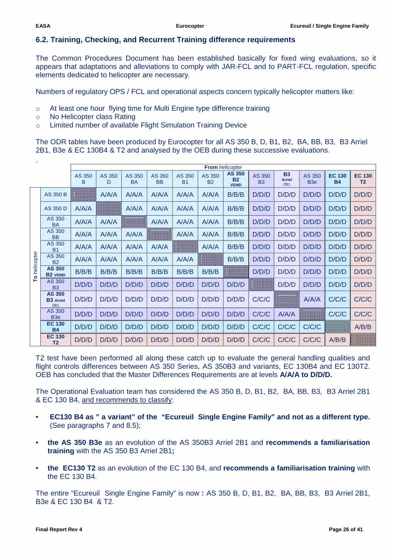
6.2. Training, Checking, and Recurrent Training dif ference requirements The Common Procedures Document has been established basically for fixed wing evaluations, so it appears that adaptations and alleviations to comply with JAR-FCL and to PART-FCL regulation, specific elements dedicated to helicopter are necessary. Numbers of regulatory OPS / FCL and operational aspects concern typically helicopter matters like: o At least one hour flying time for Multi Engine type difference training o No Helicopter class Rating o Limited number of available Flight Simulation Training Device The ODR tables have been produced by Eurocopter for all AS 350 B, D, B1, B2, BA, BB, B3, B3 Arriel 2B1, B3e & EC 130B4 & T2 and analysed by the OEB during these successive evaluations. .
From helicopter
AS 350
B AS 350
D AS 350
BA AS 350
BB AS 350
B1 AS 350
B2
AS 350 B2
VEMD
AS 350 B3
B3 Arriel 2B1
AS 350 B3e
EC 130 B4
EC 130 T2
To
hel
icop
ter
AS 350 B
A/A/A A/A/A A/A/A A/A/A A/A/A B/B/B D/D/D D/D/D D/D/D D/D/D D/D/D
AS 350 D
A/A/A A/A/A A/A/A A/A/A A/A/A B/B/B D/D/D D/D/D D/D/D D/D/D D/D/D
AS 350 BA A/A/A A/A/A A/A/A A/A/A A/A/A B/B/B D/D/D D/D/D D/D/D D/D/D D/D/D
AS 350 BB A/A/A A/A/A A/A/A A/A/A A/A/A B/B/B D/D/D D/D/D D/D/D D/D/D D/D/D
AS 350 B1 A/A/A A/A/A A/A/A A/A/A A/A/A B/B/B D/D/D D/D/D D/D/D D/D/D D/D/D
AS 350 B2 A/A/A A/A/A A/A/A A/A/A A/A/A B/B/B D/D/D D/D/D D/D/D D/D/D D/D/D
AS 350 B2 VEMD B/B/B B/B/B B/B/B B/B/B B/B/B B/B/B D/D/D D/D/D D/D/D D/D/D D/D/D
AS 350 B3 D/D/D D/D/D D/D/D D/D/D D/D/D D/D/D D/D/D D/D/D D/D/D D/D/D D/D/D
AS 350 B3 Arriel
2B1 D/D/D D/D/D D/D/D D/D/D D/D/D D/D/D D/D/D C/C/C A/A/A C/C/C C/C/C
AS 350 B3e D/D/D D/D/D D/D/D D/D/D D/D/D D/D/D D/D/D C/C/C A/A/A C/C/C C/C/C
EC 130 B4 D/D/D D/D/D D/D/D D/D/D D/D/D D/D/D D/D/D C/C/C C/C/C C/C/C A/B/B
EC 130 T2 D/D/D D/D/D D/D/D D/D/D D/D/D D/D/D D/D/D C/C/C C/C/C C/C/C A/B/B
T2 test have been performed all along these catch up to evaluate the general handling qualities and flight controls differences between AS 350 Series, AS 350B3 and variants, EC 130B4 and EC 130T2. OEB has concluded that the Master Differences Requirements are at levels A/A/A to D/D/D. The Operational Evaluation team has considered the AS 350 B, D, B1, B2, BA, BB, B3, B3 Arriel 2B1 & EC 130 B4, and recommends to classify:
• EC130 B4 as ” a variant” of the “Ecureuil Single Engine Family” and not as a different type.
(See paragraphs 7 and 8.5);
• the AS 350 B3e as an evolution of the AS 350B3 Arriel 2B1 and recommends a familiarisation training with the AS 350 B3 Arriel 2B1;
• the EC130 T2 as an evolution of the EC 130 B4, and recommends a familiarisation training with the EC 130 B4.
The entire “Ecureuil Single Engine Family” is now : AS 350 B, D, B1, B2, BA, BB, B3, B3 Arriel 2B1, B3e & EC 130 B4 & T2.
EASA Eurocopter Ecureuil / Single Engine Family
Final Report Rev 4 Page 27 of 41
7. Type Rating List and Licence Endorsement List
7.1 Type Rating List
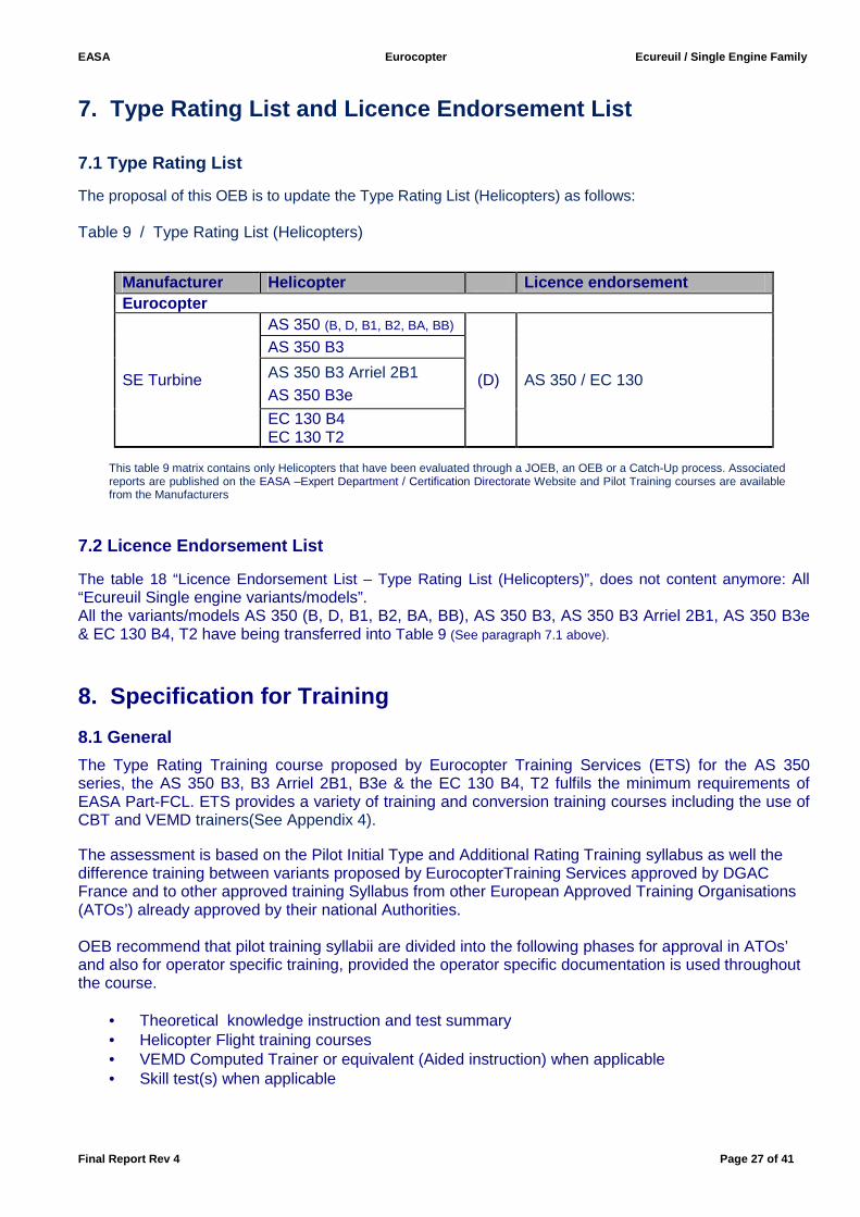
The proposal of this OEB is to update the Type Rating List (Helicopters) as follows: Table 9 / Type Rating List (Helicopters)
Manufacturer
Helicopter Licence endorsement Eurocopter
SE Turbine
AS 350 (B, D, B1, B2, BA, BB)
(D) AS 350 / EC 130
AS 350 B3
AS 350 B3 Arriel 2B1 AS 350 B3e
EC 130 B4 EC 130 T2
This table 9 matrix contains only Helicopters that have been evaluated through a JOEB, an OEB or a Catch-Up process. Associated reports are published on the EASA –Expert Department / Certification Directorate Website and Pilot Training courses are available from the Manufacturers
7.2 Licence Endorsement List
The table 18 “Licence Endorsement List – Type Rating List (Helicopters)”, does not content anymore: All “Ecureuil Single engine variants/models”. All the variants/models AS 350 (B, D, B1, B2, BA, BB), AS 350 B3, AS 350 B3 Arriel 2B1, AS 350 B3e & EC 130 B4, T2 have being transferred into Table 9 (See paragraph 7.1 above).
8. Specification for Training
8.1 General
The Type Rating Training course proposed by Eurocopter Training Services (ETS) for the AS 350 series, the AS 350 B3, B3 Arriel 2B1, B3e & the EC 130 B4, T2 fulfils the minimum requirements of EASA Part-FCL. ETS provides a variety of training and conversion training courses including the use of CBT and VEMD trainers(See Appendix 4). The assessment is based on the Pilot Initial Type and Additional Rating Training syllabus as well the difference training between variants proposed by EurocopterTraining Services approved by DGAC France and to other approved training Syllabus from other European Approved Training Organisations (ATOs’) already approved by their national Authorities.
OEB recommend that pilot training syllabii are divided into the following phases for approval in ATOs’ and also for operator specific training, provided the operator specific documentation is used throughout the course.
• Theoretical knowledge instruction and test summary • Helicopter Flight training courses • VEMD Computed Trainer or equivalent (Aided instruction) when applicable • Skill test(s) when applicable

EASA Eurocopter Ecureuil / Single Engine Family
Final Report Rev 4 Page 28 of 41
8.2 Course pre-entry requirements
All students must fulfil the requirements of PART-FCL Subpart H for an initial single-engine, single-Pilot helicopter Type Rating Training course.
8.3 Licensing requirements
The AMC2 FCL.725 (a) of the Part –FCL requires for an Initial issue of a SPH, SET (H) under 3175Kg , an approved flight instruction of at least 5 flight hours and for an additional type an approved flight instruction of at least 2 flight hours, in the helicopter excluding skill test. (See Appendix 2). Note: These requirements have to be considered as the bare minimum, additional training could be necessary depending on: • complexity of the aircraft type, handling caracteristics, level of technology • previous experience of the applicant • the availability of FSTDs
8.4 Initial, Additional Type Rating & Difference tr aining courses
8.4.1 Initial Type Rating (ITR)
Candidates for an Initial AS 350 series, or AS 350 B3, AS 350 B3 Arriel 2B1, AS 350B3e or EC 130 B4 & T2 Type Rating must:
• Hold a valid Pilot license,
• Comply with the requirements set out in Part –FCL Subpart H – Section 1 & 3 and AMC1 FCL.725 (a) II.
8.4.2 Additional Type Rating (ATR)
Candidates for an Additional AS 350 series, or AS 350 B3, AS 350 B3 Arriel 2B1, AS 350B3e or EC 130 B4 & T2 Type Rating must:
• Hold a valid Pilot license,
• Hold a Single Engine Turbine Pilot Type Rating
• Comply with the requirements set out in Part –FCL Subpart H – Section 1 & 3., and AMC1 FCL.725 (a) II.
EASA Eurocopter Ecureuil / Single Engine Family
Final Report Rev 4 Page 29 of 41
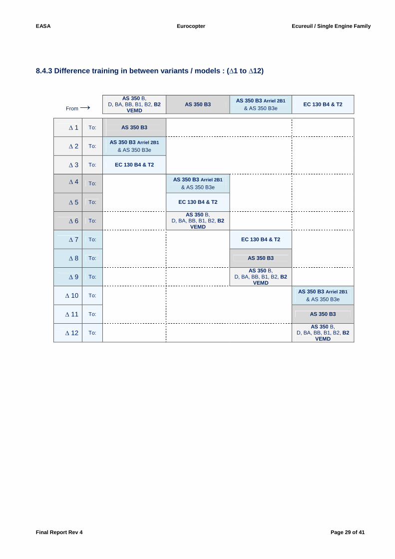
8.4.3 Difference training in between variants / mod els : (∆1 to ∆12)
From →
AS 350 B, D, BA, BB, B1, B2, B2
VEMD AS 350 B3
AS 350 B3 Arriel 2B1
& AS 350 B3e EC 130 B4 & T2
∆ 1 To:
AS 350 B3
∆ 2 To: AS 350 B3 Arriel 2B1
& AS 350 B3e
∆ 3 To: EC 130 B4 & T2
∆ 4 To:
AS 350 B3 Arriel 2B1
& AS 350 B3e
∆ 5 To: EC 130 B4 & T2
∆ 6 To:
AS 350 B, D, BA, BB, B1, B2, B2
VEMD
∆ 7 To:
EC 130 B4 & T2
∆ 8 To:
AS 350 B3
∆ 9 To:
AS 350 B,
D, BA, BB, B1, B2, B2 VEMD
∆ 10 To:
AS 350 B3 Arriel 2B1
& AS 350 B3e
∆ 11 To:
AS 350 B3
∆ 12 To:
AS 350 B,
D, BA, BB, B1, B2, B2 VEMD
EASA Eurocopter Ecureuil / Single Engine Family
Final Report Rev 4 Page 30 of 41
∆1: from AS 350 series to the AS 350 B3,
∆ 2: from AS 350 series to the AS 350 B3 Arriel 2B or AS 350 B3e,
∆ 3: from AS 350 series to the EC 130 B4 & T2:
The applicant must: Have attended the planned theoretical training and proved that he/she has passed a proficiency check on AS 350 series within the twelve months preceding the differences-highlighting course, prior to begin the training.
∆ 4: from AS 350 B3 to the AS 350 B3 Arriel 2B1 or AS 350 B3e,
∆ 5: from AS 350 B3 to the EC 130 B4 & T2,
∆ 6: from AS 350 B3 to the AS 350 series: The applicant must: Have attended the planned theoretical training and proved that he/she has passed a proficiency check on AS 350 B3 within the twelve months preceding the differences-highlighting course, prior to begin the training.
∆ 7: from AS 350 B3 Arriel 2B1 or AS 350 B3e, to the EC 130 B4 & T2,
∆ 8: from AS 350 B3 Arriel 2B1 or AS 350 B3e, to the AS 350 B3,
∆ 9: from AS 350 B3 Arriel 2B1 or AS 350 B3e, to the AS 350 series:
The applicant must: Have attended the planned theoretical training and proved that he/she has passed a proficiency check on AS 350 B3 Arriel 2B1 and AS 350 B3e, within the twelve months preceding the differences-highlighting course, prior to begin the training.
∆10: from EC 130 B4 & T2 to the AS 350 B3 Arriel 2B1 or AS 350 B3e,
∆11: from EC 130 B4 & T2 to the AS 350 B3,
∆12: from EC 130 B4 & T2 to the AS 350 series:
The applicant must: Have attended the planned theoretical training and proved that he/she has passed a proficiency check on EC 130 B4 & T2 within the twelve months preceding the differences-highlighting course, prior to begin the training.
EASA Eurocopter Ecureuil / Single Engine Family
Final Report Rev 4 Page 31 of 41
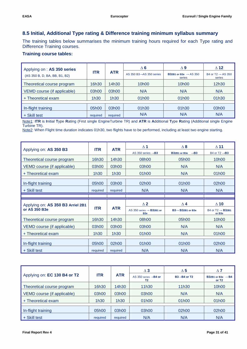
8.5 Initial, Additional Type rating & Difference tr aining minimum syllabus summary
The training tables below summarises the minimum training hours required for each Type rating and Difference Training courses.
Training course tables:
Applying on : AS 350 series (AS 350 B, D, BA, BB, B1, B2)
ITR ATR ∆ 6 ∆ 9 ∆ 12
AS 350 B3→AS 350 series B32B1 or B3e → AS 350 series
B4 or T2 → AS 350 series
Theoretical course program 16h30 14h30 10h00 10h00 12h30
VEMD course (if applicable) 03h00 03h00 N/A N/A N/A
+ Theoretical exam 1h30 1h30 01h00 01h00 01h30
In-flight training 05h00 03h00 01h30 01h30 03h00
+ Skill test required required N/A N/A N/A
Note1: ITR is Initial Type Rating (First single EngineTurbine TR) and ATR is Additional Type Rating (Additional single Engine Turbine TR). Note2: When Flight time duration indicates 01h30, two flights have to be performed, including at least two engine starting.
Applying on: AS 350 B3 ITR ATR ∆ 1 ∆ 8 ∆ 11
AS 350 series →B3 B32B1 or B3e →B3 B4 or T2 →B3
Theoretical course program 16h30 14h30 08h00 05h00 10h00
VEMD course (if applicable) 03h00 03h00 03h00 N/A N/A
+ Theoretical exam 1h30 1h30 01h00 N/A 01h00
In-flight training 05h00 03h00 02h00 01h00 02h00
+ Skill test required required N/A N/A N/A
Applying on: AS 350 B3 Arriel 2B1 or AS 350 B3e ITR ATR
∆ 2 ∆ 4 ∆ 10 AS 350 series → B32B1 or
B3e B3→ B32B1 or B3e B4 or T2 → B32B1
or B3e
Theoretical course program 16h30 14h30 08h00 05h00 10h00
VEMD course (if applicable) 03h00 03h00 03h00 N/A N/A
+ Theoretical exam 1h30 1h30 01h00 N/A 01h00
In-flight training 05h00 02h00 01h00 01h00 02h00
+ Skill test required required N/A N/A N/A
Applying on: EC 130 B4 or T2 ITR ATR ∆ 3 ∆ 5 ∆ 7
AS 350 series →B4 or T2
B3→B4 or T2 B3 2B1 or B3e → B4 or T2
Theoretical course program 16h30 14h30 11h30 11h30 10h00
VEMD course (if applicable) 03h00 03h00 03h00 N/A N/A
+ Theoretical exam 1h30 1h30 01h00 01h00 01h00
In-flight training 05h00 03h00 03h00 02h00 02h00
+ Skill test required required N/A N/A N/A
EASA Eurocopter Ecureuil / Single Engine Family
Final Report Rev 4 Page 32 of 41
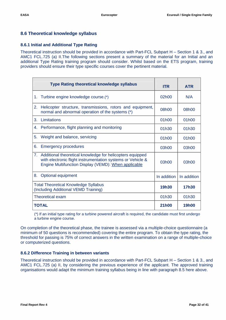
8.6 Theoretical knowledge syllabus
8.6.1 Initial and Additional Type Rating
Theoretical instruction should be provided in accordance with Part-FCL Subpart H – Section 1 & 3., and AMC1 FCL.725 (a) II.The following sections present a summary of the material for an Initial and an additional Type Rating training program should consider. Whilst based on the ETS program, training providers should ensure their type specific courses cover the pertinent material.
(*) If an initial type rating for a turbine powered aircraft is required, the candidate must first undergo
a turbine engine course. On completion of the theoretical phase, the trainee is assessed via a multiple-choice questionnaire (a minimum of 50 questions is recommended) covering the entire program. To obtain the type rating, the threshold for passing is 75% of correct answers in the written examination on a range of multiple-choice or computerized questions. 8.6.2 Difference Training in between variants
Theoretical instruction should be provided in accordance with Part-FCL Subpart H – Section 1 & 3., and AMC1 FCL.725 (a) II, by considering the previous experience of the applicant. The approved training organisations would adapt the minimum training syllabus being in line with paragraph 8.5 here above.
Type Rating theoretical knowledge syllabus ITR
ATR
1. Turbine engine knowledge course.(*) 02h00 N/A
2. Helicopter structure, transmissions, rotors and equipment, normal and abnormal operation of the systems (*) 08h00 08h00
3. Limitations 01h00 01h00
4. Performance, flight planning and monitoring 01h30 01h30
5. Weight and balance, servicing 01h00 01h00
6. Emergency procedures 03h00 03h00
7. Additional theoretical knowledge for helicopters equipped with electronic flight instrumentation systems or Vehicle & Engine Multifunction Display (VEMD): When applicable
03h00 03h00
8. Optional equipment In addition In addition
Total Theoretical Knowledge Syllabus (Including Additional VEMD Training)
19h30 17h30
Theoretical exam 01h30 01h30
TOTAL 21h00 19h00
EASA Eurocopter Ecureuil / Single Engine Family
Final Report Rev 4 Page 33 of 41
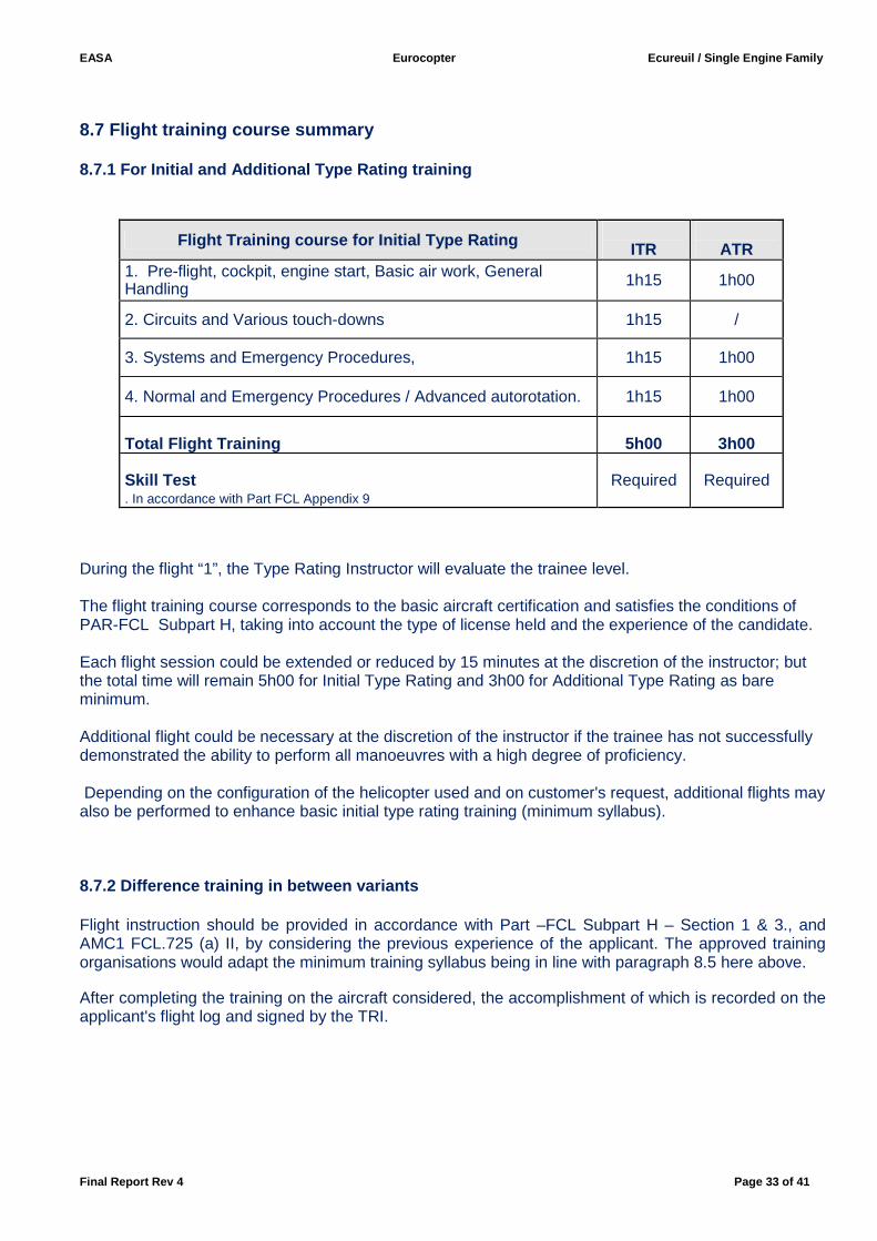
8.7 Flight training course summary 8.7.1 For Initial and Additional Type Rating traini ng
Flight Training course for Initial Type Rati ng ITR
ATR
1. Pre-flight, cockpit, engine start, Basic air work, General Handling 1h15 1h00
2. Circuits and Various touch-downs 1h15 /
3. Systems and Emergency Procedures, 1h15 1h00
4. Normal and Emergency Procedures / Advanced autorotation. 1h15 1h00
Tota l Flight Training
5h00
3h00
Skill Test . In accordance with Part FCL Appendix 9
Required Required
During the flight “1”, the Type Rating Instructor will evaluate the trainee level. The flight training course corresponds to the basic aircraft certification and satisfies the conditions of PAR-FCL Subpart H, taking into account the type of license held and the experience of the candidate. Each flight session could be extended or reduced by 15 minutes at the discretion of the instructor; but the total time will remain 5h00 for Initial Type Rating and 3h00 for Additional Type Rating as bare minimum. Additional flight could be necessary at the discretion of the instructor if the trainee has not successfully demonstrated the ability to perform all manoeuvres with a high degree of proficiency. Depending on the configuration of the helicopter used and on customer's request, additional flights may also be performed to enhance basic initial type rating training (minimum syllabus). 8.7.2 Difference training in between variants Flight instruction should be provided in accordance with Part –FCL Subpart H – Section 1 & 3., and AMC1 FCL.725 (a) II, by considering the previous experience of the applicant. The approved training organisations would adapt the minimum training syllabus being in line with paragraph 8.5 here above. After completing the training on the aircraft considered, the accomplishment of which is recorded on the applicant's flight log and signed by the TRI.
EASA Eurocopter Ecureuil / Single Engine Family
Final Report Rev 4 Page 34 of 41
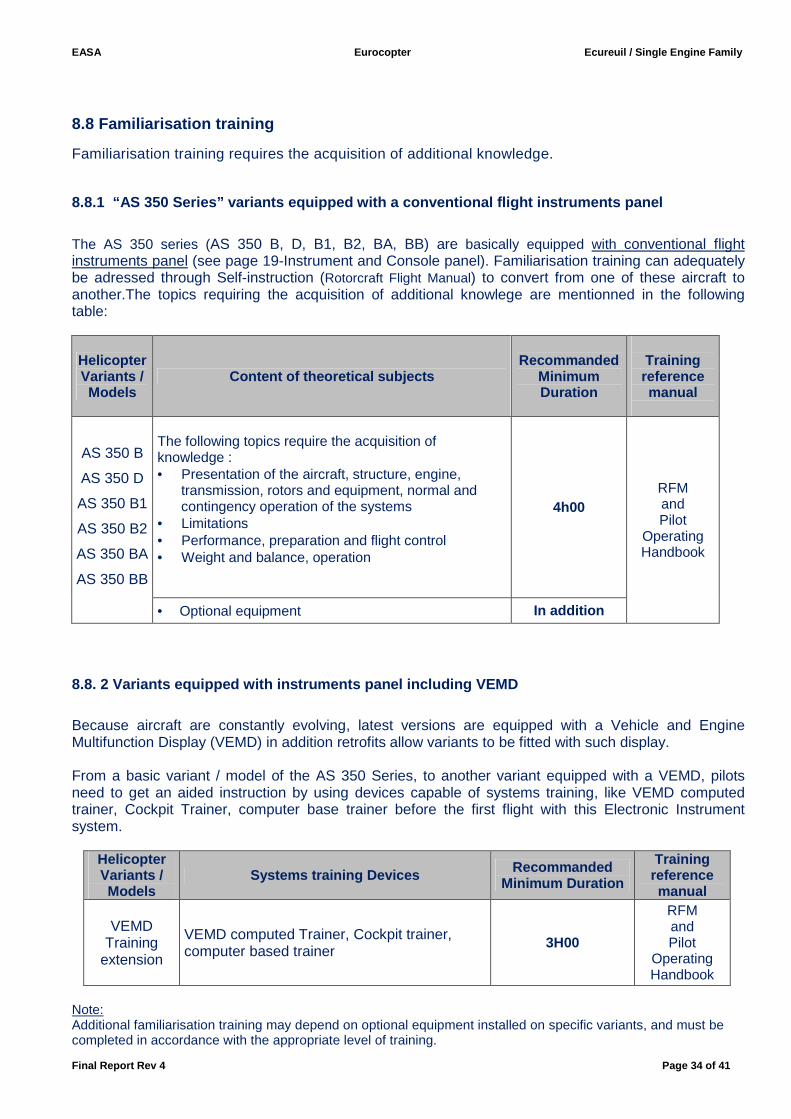
8.8 Familiarisation training
Familiarisation training requires the acquisition of additional knowledge.
8.8.1 “AS 350 Series” variants equipped with a con ventional flight instruments panel
The AS 350 series (AS 350 B, D, B1, B2, BA, BB) are basically equipped with conventional flight instruments panel (see page 19-Instrument and Console panel). Familiarisation training can adequately be adressed through Self-instruction (Rotorcraft Flight Manual) to convert from one of these aircraft to another.The topics requiring the acquisition of additional knowlege are mentionned in the following table:
Helicopter Variants / Models
Content of theoretical subjects Recommanded
Minimum Duration
Training reference manual
AS 350 B
AS 350 D
AS 350 B1
AS 350 B2
AS 350 BA
AS 350 BB
The following topics require the acquisition of knowledge : • Presentation of the aircraft, structure, engine,
transmission, rotors and equipment, normal and contingency operation of the systems
• Limitations • Performance, preparation and flight control • Weight and balance, operation
4h00 RFM and Pilot
Operating Handbook
• Optional equipment In addition
8.8. 2 Variants equipped with instruments panel inc luding VEMD
Because aircraft are constantly evolving, latest versions are equipped with a Vehicle and Engine Multifunction Display (VEMD) in addition retrofits allow variants to be fitted with such display. From a basic variant / model of the AS 350 Series, to another variant equipped with a VEMD, pilots need to get an aided instruction by using devices capable of systems training, like VEMD computed trainer, Cockpit Trainer, computer base trainer before the first flight with this Electronic Instrument system.
Helicopter Variants / Models
Systems training Devices Recommanded Minimum Duration
Training reference manual
VEMD Training
extension
VEMD computed Trainer, Cockpit trainer, computer based trainer
3H00
RFM and Pilot
Operating Handbook
Note: Additional familiarisation training may depend on optional equipment installed on specific variants, and must be completed in accordance with the appropriate level of training.
EASA Eurocopter Ecureuil / Single Engine Family
Final Report Rev 4 Page 35 of 41
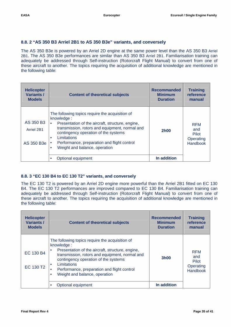
8.8. 2 “ AS 350 B3 Arriel 2B1 to AS 350 B3e” variants, and c onversely
The AS 350 B3e is powered by an Arriel 2D engine at the same power level than the AS 350 B3 Arriel 2B1. The AS 350 B3e performances are similar than AS 350 B3 Arriel 2B1. Familiarisation training can adequately be addressed through Self-instruction (Rotorcraft Flight Manual) to convert from one of these aircraft to another. The topics requiring the acquisition of additional knowledge are mentioned in the following table:
Helicopter Variants / Models
Content of theoretical subjects Recommanded
Minimum Duration
Training reference manual
AS 350 B3
Arriel 2B1
AS 350 B3e
The following topics require the acquisition of knowledge : • Presentation of the aircraft, structure, engine,
transmission, rotors and equipment, normal and contingency operation of the systems
• Limitations • Performance, preparation and flight control • Weight and balance, operation
2h00 RFM and Pilot
Operating Handbook
• Optional equipment In addition
8.8. 3 “EC 130 B4 to EC 130 T2” variants, and conve rsely
The EC 130 T2 is powered by an Arriel 2D engine more powerful than the Arriel 2B1 fitted on EC 130 B4. The EC 130 T2 performances are improved compared to EC 130 B4. Familiarisation training can adequately be addressed through Self-instruction (Rotorcraft Flight Manual) to convert from one of these aircraft to another. The topics requiring the acquisition of additional knowledge are mentioned in the following table:
Helicopter Variants / Models
Content of theoretical subjects Recommended
Minimum Duration
Training reference manual
EC 130 B4
EC 130 T2
The following topics require the acquisition of knowledge : • Presentation of the aircraft, structure, engine,
transmission, rotors and equipment, normal and contingency operation of the systems
• Limitations • Performance, preparation and flight control • Weight and balance, operation
3h00 RFM and Pilot
Operating Handbook
• Optional equipment In addition
EASA Eurocopter Ecureuil / Single Engine Family
Final Report Rev 4 Page 36 of 41
8.9 Training Areas of Specific Emphasis (TASE)
The following procedures for training should receive special attention. Since, although they relate to separate issues, they are inter-connected. Flight Instructors and Type Rating Instructors should take into account across the whole fleet AS 350 and EC 130, that Pilot Training methodology and demonstration methodology are linked. Therefore the OEB supports the manufacturer recommendations and training providers should consider the following elements: 8.9.1 TASE / Pilot Training Methodology
• Autorotation / Engine off landing:
Autorotation training shall be performed with a Trainee and an Instructor only. Autorotation training as mentioned in the RFM shall be conducted within gliding distance of a running landing suitable area.
The engine reduction to idle position shall be completed when the helicopter is in autorotative descent and established on the glide path for the appropriate suitable area:
- Perform first attempt Power on (Fuel Flow Control Lever or twist grip on flight position), execute the flare then go around then,
- Perform the autorotation training / Engine off landing (FFCL at 67/70 % Ng or twist grip on idle position).
- Check engine rating.
Notes:
- On AS 350 Series, equipped with FFCL fitted on the cabin floor: from 67/70 % Ng to the Flight position, the lever must be managed cautiously.
- On B3 Arriel 2B1, it needs a maximum of 8 seconds to recover the engine flight rating using the manual twist grip(See RFM Section 8.3)
- On B3 Arriel 2B1, B3e and EC 130 B4 & T2, if needed it is possible to quickly switch back to the flight detent of the twist grip, at any time and for any NR value.
Pay attention to the following:
- Do not lower the nose too abruptly when power is reduced, to avoid a dive, - Maintain proper NR during the descent, - Wait to apply the collective pitch at a correct height to avoid hard landing, loss of heading control,
and possible damage to the tail rotor and to the main rotor blade stops, - Use sufficient anti-torque pedal travel when power is reduced, especially on EC130B4 & T2 with
Fenestron. - Keep in mind that a higher All Up Weight increases the risk of NR overspeed and hard landing.
EASA Eurocopter Ecureuil / Single Engine Family
Final Report Rev 4 Page 37 of 41
AS 350 Series equipped with FFCL fitted on the cabin floor: - When FFCL is reduced to 67/70 %Ng, take care to not reduce more, to avoid an engine flame out. - There is no mechanical idle notch and the Instructor must adjust the FFCL. - For go-around maneuver, anticipate the decision process: - A quick repositioning of the FFCL above the flight detent can lead to a rotor and engine
overspeed. AS 350 B3:
- Pilot must check that the Flight stop twist Grip locking device is locked, before turning the twist-grip to the flight position
EC 130 B4 & T2:
- Mind the important ground effect of the large fuselage when leveling the helicopter after the flare.
• Simulated Hydraulic failure
(Except EC 130 B4 & T2 and AS 350 B3 equipped with the optional dual hydraulic system):
- In steady flight conditions, simulate the hydraulic failure by depressing HYD TEST push button on the System Control Unit (Honeywell or SCU console panel): HYD + Gong sounds while the student adjusts speed to obtain between 40 and 60 Kt. CAUTION: The Instructor must ensure that the trainee adjusts the speed and attitude prior to isolating the hydraulics. - Once safety speed is set, and prior to activating the hydraulic isolation switch reset HYD TEST pushbutton to restore hydraulic pressure in tail rotor accumulator (except for AS 350 B3e). - Control loads increase with speed. As control loads increase, be careful not to inadvertently move twist grip out of FLIGHT detent, - If necessary during the training exercise, hydraulic assistance can be recovered immediately by setting the HYD TEST push button to the UP position or by resetting the hydraulic cut off switch to ON. - If the HYD TEST pushbutton is not reset on the control panel, no hydraulic assistance can be restored. Before hydraulic isolation with the switch on the collective lever, do not forget to reset the HYD pushbutton on the console. - Do not let the student attempt hover flight or low speed maneuver, as the intensity and direction of the control feedback force will change rapidly. This will result in a loss of control, On previous versions of AS350 equipped with a HONEYWELL console control, do not silence the HORN by using the HORN switch. The HORN will be silenced when the pilot selects the hydraulic cut-off switch to off. If the pilot uses the HORN switch to silence the HORN before using the hydraulic cut-off switch, this crucial step could be forgotten. This could then result in significant unbalanced lateral cyclic feedback forces, especially at low speed, if one of the lateral accumulators depletes before the other one. In addition, de-activating the HORN using the HORN switch, makes it unavailable to warn the pilot of low or high rotor RPM.
EASA Eurocopter Ecureuil / Single Engine Family
Final Report Rev 4 Page 38 of 41
Pay attention to the following:
- Hydraulic accumulators gives energy during approximately 20 seconds, in proportion of controls movements, so reduce to safety speed in this time frame,
- Anticipate to perform a shallow approach,
- Perform a running landing,
- Hover flight or any low speed maneuver must be avoided,
- Keep in mind that higher All Up Weight increase the risk of aircraft loss of control at low speed,
- The statistics show that failure to strictly comply with the procedure consequently increases the risk level.
Notes:
Left hand collective lever is not equipped with “HY D” switch,
- To be well prepared, brief your Trainee for setting the collective lever HYD switch to on, if necessary.
- If the Instructor decides to take over the controls, he must plan to continue the flight up to the landing without the hydraulic assistance.
- CAUTION: when hydraulic pressure is restored in flight, the forces disappear which can lead to an abrupt left roll movement.
- Anticipate the power application to avoid induced increase in nose-up attitude.
• Simulated single channel FADEC failures (B3 version only):
Resetting to AUTO mode after manual fuel flow training may activate the idle switch leading to a loss of power. Reselection to AUTO should only be made on ground after landing or in a flight condition allowing a landing in autorotation. It is possible to switch back the AUTO / MANU selector to the automatic fuel control mode (AUTO mode) at any time and for any NR value. In all cases, the NR must be controlled so that the max NR alarm is never activated. At the end of the exercise check that the twist grip is correctly in the FLIGHT position. Before MOD 07 3222: The time spent in FADEC failure training configuration, with “AUTO/MANU” governing mode selector set to “MAN”, shall not exceed 15 consecutive minutes. Wait at least 15 minutes between two operations on “MAN” setting even if it has been selected only for a few seconds. Before MOD 07 3084: Reset the switch for twist grip lock in order to re-engage the flight stop locking device. Pay attention to the following:
- Take care to use twist grip in the correct way.
- Apply slight collective variations on short final.
- After the touchdown, lower the collective pitch after reducing the fuel flow.
- The Instructor has to be prepared to an excessive variation of the Twist Grip when Trainee is in manual governing.
- Practice this single channel FADEC failure training only when in stabilized flight.
EASA Eurocopter Ecureuil / Single Engine Family
Final Report Rev 4 Page 39 of 41
• Twist-grip and FFCL condition of use:
When in simulated hydraulic failure training on AS 350 B3 Arriel 2B1 or AS 350 B3e: Control loads increase with speed. As control loads increase, be careful not to inadvertently move twist grip out of FLIGHT detent (Simulated hydraulic failure on AS 350 B3 Arriel 2B1 or AS 350 B3e). When in simulated Single channel FADEC failure training on AS 350 B3: - Take care to not use twist grip on the opposite way. - At the end of the exercise check that FLIGHT detent stop is reset in back position. Before MOD 07 3084: Reset the switch for twist grip lock in order to re-engage the flight stop locking device. Simulated engine failure on AS 350 B3, AS 350 B3 Arriel 2B1 or AS 350 B3e : - On the AS 350 B3 Arriel 2B1 or AS 350 B3e , the twist-grip returns to the FLIGHT position with the spring load assistance as soon as the grip is out of the idle notch, and there is no friction. - On the B3, the twist-grip friction must be fully released before starting the autorotation training and the twist-grip is not fitted with a spring load. Simulated engine failure on AS 350 B/BA/B1/B2: - To prevent an engine flame out, when reducing power, make sure to maintain the NG above 67%. - A quick repositioning of the fuel flow control lever above the flight position can lead to rotor and engine overspeed. 8.9.2 TASE / Demonstration methodology for Flight Instructors an d Type Rating Instructors:
• Servo-transparency (called also servo-reversibility):
Except for EC 130 B4 and AS 350 B3 Arriel 2B1 & AS 350 B3e when fitted with dual Hydraulic system.
The servo-transparency training could be performed in the following way:
- Complete procedure should be performed above 1000 ft (AGL), - Achieve airspeed between 130 and VNE (with a rate of descend), - Perform a 30° left turn, - Slowly increase the load factor by a backwards cyclic action, - When the servo-transparency is achieved, the tendency of the aircraft is to pitch up and turn to the right, - As soon as the load decreases, servo-transparency disappears
Pay attention to the following:
- Due to control loads linked to servo-transparency, the collective pitch tendency is to decrease. The collective pitch decrease and the pitch up may lead to rpm increase.
- The procedure should not be done too aggressively
- The exercise is easier when high All Up Weight is important and/or high density altitude.
EASA Eurocopter Ecureuil / Single Engine Family
Final Report Rev 4 Page 40 of 41
• Tail-Rotor control failure:
- Plan to use the entire length of the RWY, - Landing is made easier by landing with a RH wind component (and light weight) and could be not possible with LH wind component, - When airspeed is lower than 20 Kt, go-around is impossible due to loss of vertical fin efficiency, - In a real T/R control failure, using a hard surfaced runway may allow for a light sideslip. Training procedure in such conditions should be performed with protective skid shoes. - It is recommended to perform a shallow approach at the end; during the speed reduction close to the ground, remember to slightly push the cyclic forward during sideslip cancelation to maintain current airspeed, taking care to avoid acceleration.
Pay attention to the following:
- Do not flare during parallel part (h/c drops quickly out of GND effect, resulting descent can only be countered by PWR application, which makes h/c yaw to the left).
- Try to be close to the ground during parallel part.
- Do not induce left yaw during parallel part.
- Proceed with a very progressive speed reduction.
- Do not touch down in sideslip position, especially when landing on grass landing area.
9. Specification for Testing & Checking & Recent E xperience 9.1 Skill test
As required by Part-FCL Appendix 9 9.2 Proficiency Checks As required by Part-FCL Appendix 9
9. 3 Recent experience Recent experience as required by Part-FCL – Subpart H and JAR-OPS 3.
10. Specification for Flight Simulation Training D evices When this report has been finalized no Flight Simulation Training Devices qualified in accordance with JAR-FSTD (H) and compliant with EASA CS-FSTD (H) were available for Ecureuil / Single Engine Family.
EASA Eurocopter Ecureuil / Single Engine Family
Final Report Rev 4 Page 41 of 41
11. Application of OEB report This OEB report applies to commercial operations. However, the OEB also recommends private or corporate operations to follow the findings of this report.
12. Appendices
• Appendix 0 : Cover • Appendix 1 : EASA – TCDS. R.008 • Appendix 2 : PAR-FCL Type rating requirements • Appendix 3: Ecureuil Single Engine Family ODR and MDR Tables • Appendix 4: EUROCOPTER Pilot Type Rating Training (Approved by DGAC/France.
Notes: Appendices are available for NAA’s by request to EASA / Certification Directorate- Expert Department or to Eurocopter Manufacturer.