Embed Size (px)
Citation preview
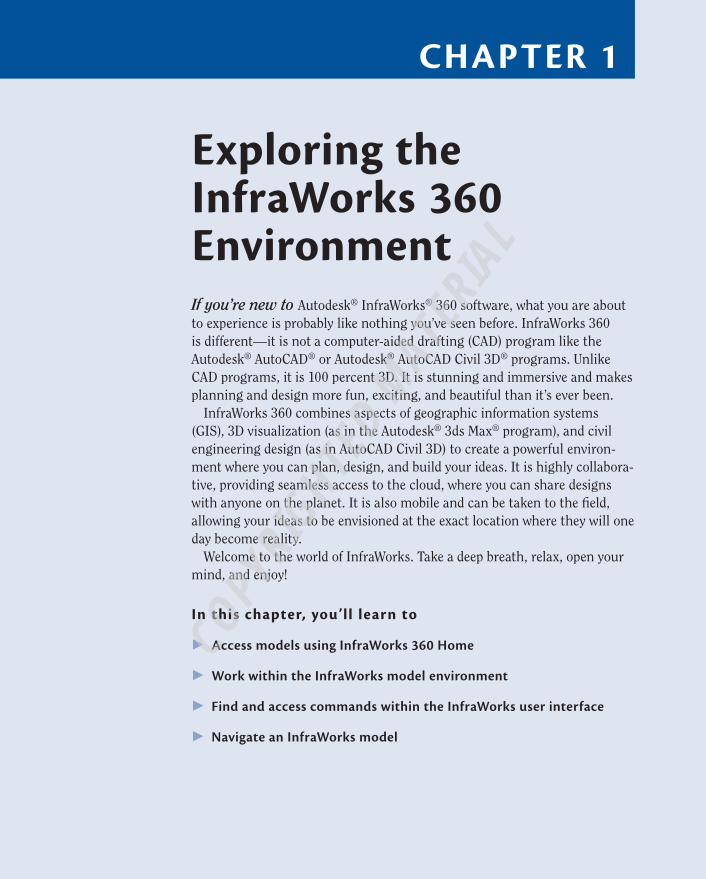
Chapter 1
exploring the InfraWorks 360 environmentIf you’re new to Autodesk® InfraWorks® 360 software, what you are about to experience is probably like nothing you’ve seen before. InfraWorks 360 is different—it is not a computer-aided drafting (CAD) program like the Autodesk® AutoCAD® or Autodesk® AutoCAD Civil 3D® programs. Unlike CAD programs, it is 100 percent 3D. It is stunning and immersive and makes planning and design more fun, exciting, and beautiful than it’s ever been.
InfraWorks 360 combines aspects of geographic information systems (GIS), 3D visualization (as in the Autodesk® 3ds Max® program), and civil engineering design (as in AutoCAD Civil 3D) to create a powerful environ-ment where you can plan, design, and build your ideas. It is highly collabora-tive, providing seamless access to the cloud, where you can share designs with anyone on the planet. It is also mobile and can be taken to the field, allowing your ideas to be envisioned at the exact location where they will one day become reality.
Welcome to the world of InfraWorks. Take a deep breath, relax, open your mind, and enjoy!
In this chapter, you’ll learn to
▶ Access models using InfraWorks 360 Home
▶ Work within the InfraWorks model environment
▶ Find and access commands within the InfraWorks user interface
▶ Navigate an InfraWorks model
COPYRIG
HTED M
ATERIAL
2 C h ap t e r 1 • E x p l o r i n g t h e I n f r aWo r k s 3 6 0 E n v i r o nmen t
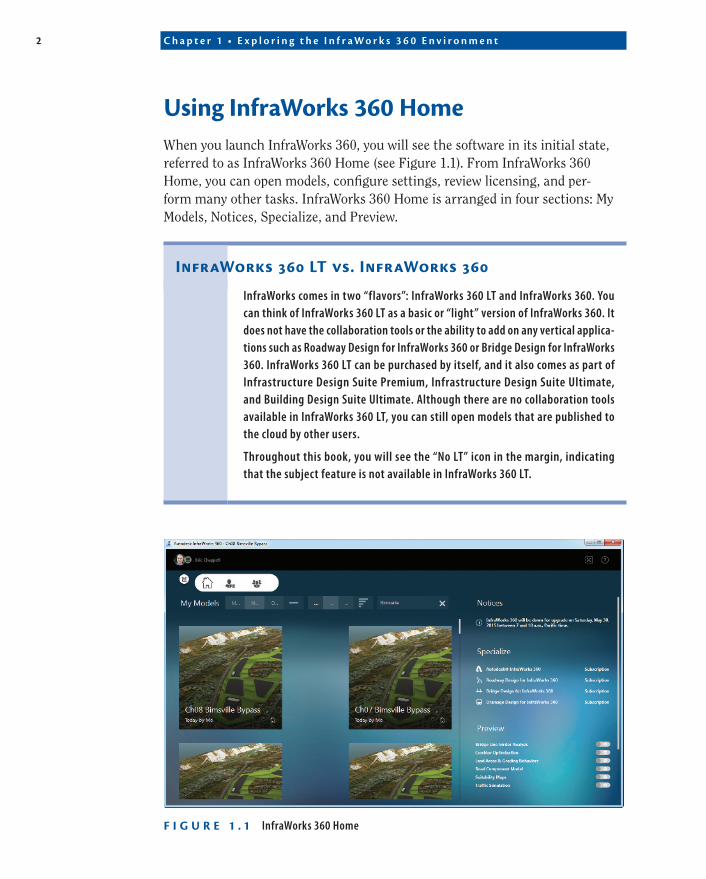
Using InfraWorks 360 homeWhen you launch InfraWorks 360, you will see the software in its initial state, referred to as InfraWorks 360 Home (see Figure 1.1). From InfraWorks 360 Home, you can open models, configure settings, review licensing, and per-form many other tasks. InfraWorks 360 Home is arranged in four sections: My Models, Notices, Specialize, and Preview.
InfraWorks 360 Lt vs. InfraWorks 360
InfraWorks comes in two “flavors”: InfraWorks 360 LT and InfraWorks 360. You can think of InfraWorks 360 LT as a basic or “light” version of InfraWorks 360. It does not have the collaboration tools or the ability to add on any vertical applica-tions such as Roadway Design for InfraWorks 360 or Bridge Design for InfraWorks 360. InfraWorks 360 LT can be purchased by itself, and it also comes as part of Infrastructure Design Suite Premium, Infrastructure Design Suite Ultimate, and Building Design Suite Ultimate. Although there are no collaboration tools available in InfraWorks 360 LT, you can still open models that are published to the cloud by other users.
Throughout this book, you will see the “No LT” icon in the margin, indicating that the subject feature is not available in InfraWorks 360 LT.
F I g U r e 1 . 1 InfraWorks 360 Home
U s i n g I n f r a W o r k s 3 6 0 H o m e 3
Using My Models to Open projectsThe My Models section of InfraWorks 360 Home displays a series of tiles that represent models you can open. This includes models that are stored on your local machine’s hard drive, on a network drive, or online within the InfraWorks 360 cloud.
Locally Stored Models
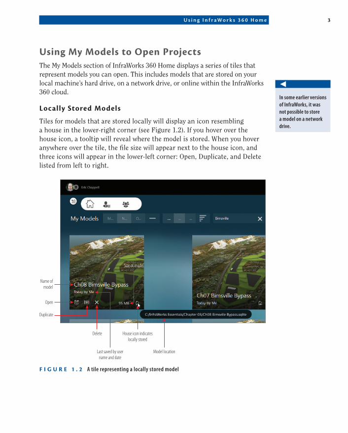
Tiles for models that are stored locally will display an icon resembling a house in the lower-right corner (see Figure 1.2). If you hover over the house icon, a tooltip will reveal where the model is stored. When you hover anywhere over the tile, the file size will appear next to the house icon, and three icons will appear in the lower-left corner: Open, Duplicate, and Delete listed from left to right.
Delete
Size of model
Name ofmodel
Open
Duplicate
Last saved by username and date
Model location
House icon indicateslocally stored
F I g U r e 1 . 2 A tile representing a locally stored model
◀
In some earlier versions of InfraWorks, it was not possible to store a model on a network drive.
4 C h ap t e r 1 • E x p l o r i n g t h e I n f r aWo r k s 3 6 0 E n v i r o nmen t
Models Stored in the Cloud
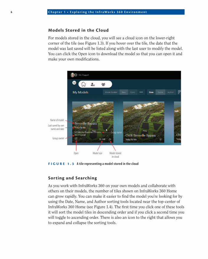
For models stored in the cloud, you will see a cloud icon on the lower-right corner of the tile (see Figure 1.3). If you hover over the tile, the date that the model was last saved will be listed along with the last user to modify the model. You can click the Open icon to download the model so that you can open it and make your own modifications.
Name of model
Last saved by username and date
Group owner
Open
Group name
Model size Model storedin cloud
F I g U r e 1 . 3 A tile representing a model stored in the cloud
Sorting and Searching
As you work with InfraWorks 360 on your own models and collaborate with others on their models, the number of tiles shown on InfraWorks 360 Home can grow rapidly. You can make it easier to find the model you’re looking for by using the Date, Name, and Author sorting tools located near the top-center of InfraWorks 360 Home (see Figure 1.4). The first time you click one of these tools it will sort the model tiles in descending order and if you click a second time you will toggle to ascending order. There is also an icon to the right that allows you to expand and collapse the sorting tools.

U s i n g I n f r a W o r k s 3 6 0 H o m e 5
Sorting toolsExpand and collapse
sorting tools
F I g U r e 1 . 4 Applying filters to control the display of tiles on InfraWorks 360 Home
You can also filter tiles based on a keyword search by simply typing a few characters in the Search field (see Figure 1.5). You can search based on model name, group name, and group owner name. When you initiate the search, it is treated as a filter, and only those tiles matching the search will be displayed. You can click the X at the right end of the Search field to clear the search.
F I g U r e 1 . 5 Using the Search field (highlighted by the red rectangle) to filter the display of tiles
Opening Models by Browsing
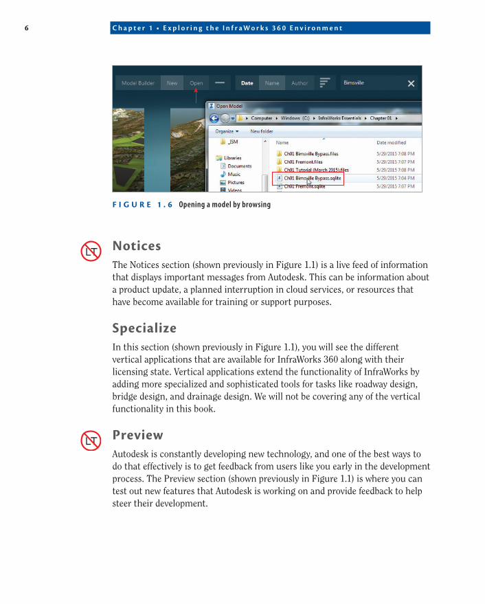
At times you may need or want to open a locally stored model without using one of the tiles on InfraWorks 360 Home. To accomplish this, you can click the white plus sign to expand the toolbar and reveal the Model Builder, New, and Open commands. To open a model by browsing, simply click Open and then navigate to the SQLite file that represents your model (see Figure 1.6).
You’ll cover Model Builder and the New commands in the next chapter.
◀
6 C h ap t e r 1 • E x p l o r i n g t h e I n f r aWo r k s 3 6 0 E n v i r o nmen t
F I g U r e 1 . 6 Opening a model by browsing
NoticesThe Notices section (shown previously in Figure 1.1) is a live feed of information that displays important messages from Autodesk. This can be information about a product update, a planned interruption in cloud services, or resources that have become available for training or support purposes.
SpecializeIn this section (shown previously in Figure 1.1), you will see the different vertical applications that are available for InfraWorks 360 along with their licensing state. Vertical applications extend the functionality of InfraWorks by adding more specialized and sophisticated tools for tasks like roadway design, bridge design, and drainage design. We will not be covering any of the vertical functionality in this book.
previewAutodesk is constantly developing new technology, and one of the best ways to do that effectively is to get feedback from users like you early in the development process. The Preview section (shown previously in Figure 1.1) is where you can test out new features that Autodesk is working on and provide feedback to help steer their development.
U s i n g I n f r a W o r k s 3 6 0 H o m e 7
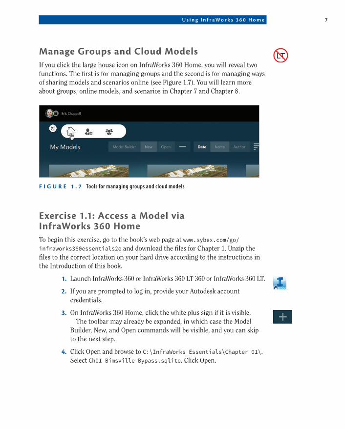
Manage groups and Cloud ModelsIf you click the large house icon on InfraWorks 360 Home, you will reveal two functions. The first is for managing groups and the second is for managing ways of sharing models and scenarios online (see Figure 1.7). You will learn more about groups, online models, and scenarios in Chapter 7 and Chapter 8.
F I g U r e 1 . 7 Tools for managing groups and cloud models
exercise 1.1: access a Model via InfraWorks 360 homeTo begin this exercise, go to the book’s web page at www.sybex.com/go/ infraworks360essentials2e and download the files for Chapter 1. Unzip the files to the correct location on your hard drive according to the instructions in the Introduction of this book.
1. Launch InfraWorks 360 or InfraWorks 360 LT 360 or InfraWorks 360 LT.
2. If you are prompted to log in, provide your Autodesk account credentials.
3. On InfraWorks 360 Home, click the white plus sign if it is visible.The toolbar may already be expanded, in which case the Model
Builder, New, and Open commands will be visible, and you can skip to the next step.
4. Click Open and browse to C:\InfraWorks Essentials\Chapter 01\. Select Ch01 Bimsville Bypass.sqlite. Click Open.
8 C h ap t e r 1 • E x p l o r i n g t h e I n f r aWo r k s 3 6 0 E n v i r o nmen t
After a time, the model will open. The amount of time will vary based on your computer. You are looking at a model of the project we’ll be working on throughout this book. It’s just a glimpse for now, but don’t worry, we’ll be spending lots of time in this model soon.
5. Click the Switch To Home icon in the upper-left corner of the InfraWorks screen to switch to InfraWorks 360 Home.
6. Locate the tile named Tutorial (June 2015). If you do not see this tile, you may need to scroll down.
7. Move your cursor over the tile named Tutorial (June 2015), and click the icon to open the Download As dialog.
8. In the Open Download As dialog, do the following:
▶ Set Location to C:\InfraWorks Essentials\.
▶ Click Download.
9. Depending on your Internet connection, this download could take a considerable amount of time. If you do not want to wait, you can click Cancel. Then use the Open command to open Ch01 Tutorial (June 2015).sqlite located at C:\InfraWorks Essentials\Chapter 01\.
You are now viewing the Tutorial (June 2015) model.
10. Click the X icon in the upper-right corner of the InfraWorks window. InfraWorks will close.
Membership has Its privileges
Why does InfraWorks 360 give you the ability to sign in? What are you signing in to? To access online models, you must have an InfraWorks 360 account. The basic version of an InfraWorks 360 account without any entitlements will enable you to view models that are shared with you. For this to happen, you must be invited to an InfraWorks 360 group, and you will be able to access any models published to that group. To publish your own models, you must own that entitle-ment and have it linked to your InfraWorks 360 account. An InfraWorks 360 account is part of the package when you buy InfraWorks 360. If you have InfraWorks 360 LT, you cannot publish models or administer groups. This arrangement has been known to change and may change by the time this book has been printed, so be sure to check the Autodesk website or work with an Autodesk representative to learn exactly what you are able to do with the products you’ve purchased.
◀
This sample model is available to anyone who has InfraWorks 360 installed and has an Autodesk account.

G e t t i n g t o K n o w t h e I n f r a W o r k s U s e r I n t e r f a c e 9
Link It Up!
If you successfully download the Tutorial (June 2015) model, you will see it appear beneath My Models, but it will have a special symbol included in the thumbnail (shown previously in Figure 1.4). This symbol means that the local model is linked to an online model, and InfraWorks provides special tools to keep them in sync.
getting to Know the InfraWorks User InterfaceInfraWorks 360 employs what has been dubbed an immersive user interface. As you viewed the model in the previous exercise, you may have noticed that the InfraWorks model took up the majority of the program window. The com-mands that you access to navigate, modify, and analyze a model are neatly tucked away in a narrow black strip and a few icons along the top of the window (see Figure 1.8).
F I g U r e 1 . 8 The immersive user interface of InfraWorks
1 0 C h ap t e r 1 • E x p l o r i n g t h e I n f r aWo r k s 3 6 0 E n v i r o nmen t
the Utility BarThe narrow black strip at the top of the InfraWorks window is called the Utility Bar. It is populated with general functions that you will use throughout a project, regardless of which type of project it is. Here is a listing of the functions that are available in the Utility Bar:
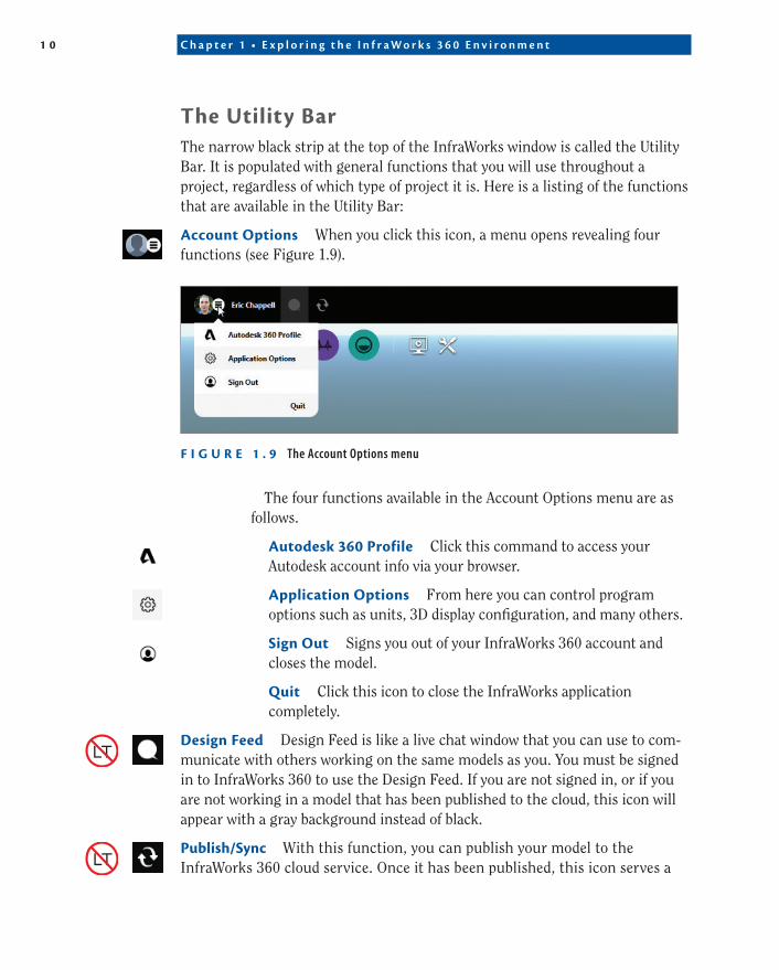
account Options When you click this icon, a menu opens revealing four functions (see Figure 1.9).
F I g U r e 1 . 9 The Account Options menu
The four functions available in the Account Options menu are as follows.
autodesk 360 profile Click this command to access your Autodesk account info via your browser.
application Options From here you can control program options such as units, 3D display configuration, and many others.
Sign Out Signs you out of your InfraWorks 360 account and closes the model.
Quit Click this icon to close the InfraWorks application completely.
Design Feed Design Feed is like a live chat window that you can use to com-municate with others working on the same models as you. You must be signed in to InfraWorks 360 to use the Design Feed. If you are not signed in, or if you are not working in a model that has been published to the cloud, this icon will appear with a gray background instead of black.
publish/Sync With this function, you can publish your model to the InfraWorks 360 cloud service. Once it has been published, this icon serves a
G e t t i n g t o K n o w t h e I n f r a W o r k s U s e r I n t e r f a c e 1 1
Sync function—exchanging updates between your local version of the model and the one stored in the cloud. You must be signed in to InfraWorks 360 to use this icon. If you are not signed in, this icon will appear with a gray back-ground instead of black.
Current proposal You’ll learn more about proposals later on in the book, but for now you can think of a proposal as a version of your design. This function shows you which version is currently being displayed and also lets you change the current version.
Undo Just as it sounds, this tool is used to undo an edit you’ve made to the model. If there is nothing to undo (for example, if you’ve just opened the model and haven’t made any changes), the icon will appear with a gray background instead of black.
redo If you change your mind about an Undo, you can use Redo to reverse it. If there is nothing to redo, this icon will appear with a gray background instead of black.
Model explorer Model Explorer presents the different elements of your model in a type of tree view. It enables you to control the visibility, display, selectability, and other things about parts of your model.
Bookmarks A bookmark is a saved view of your model. It remembers the location of your viewpoint, the direction you were viewing, and the amount that you were zoomed in or out. Models can become complex, and navigation can be tricky, so having a quick way to move around to key locations in the model can be very useful.
Full-Screen Mode In full-screen mode, the top bar of the InfraWorks window will disappear (not the Utility Bar, the part above that), and the InfraWorks window will take up all of the available space on the current monitor, obscuring everything underneath. This includes the Windows task bar. This button serves as a toggle switching between full-screen mode and normal mode.
edit Mode As you’ll learn, InfraWorks operates in one of two modes when you’re selecting objects: edit mode or select mode. In edit mode, you get more editing options such as graphical editing “handles” called gizmos and an extended shortcut menu. In select mode, an object simply highlights in yellow, and the shortcut menu is much simpler. This button turns edit mode on and its counterpart (covered next) turns select mode on.
Select Mode If you want to suppress the extra editing functions that show up when you select an object, click this button to activate select mode.
1 2 C h ap t e r 1 • E x p l o r i n g t h e I n f r aWo r k s 3 6 0 E n v i r o nmen t
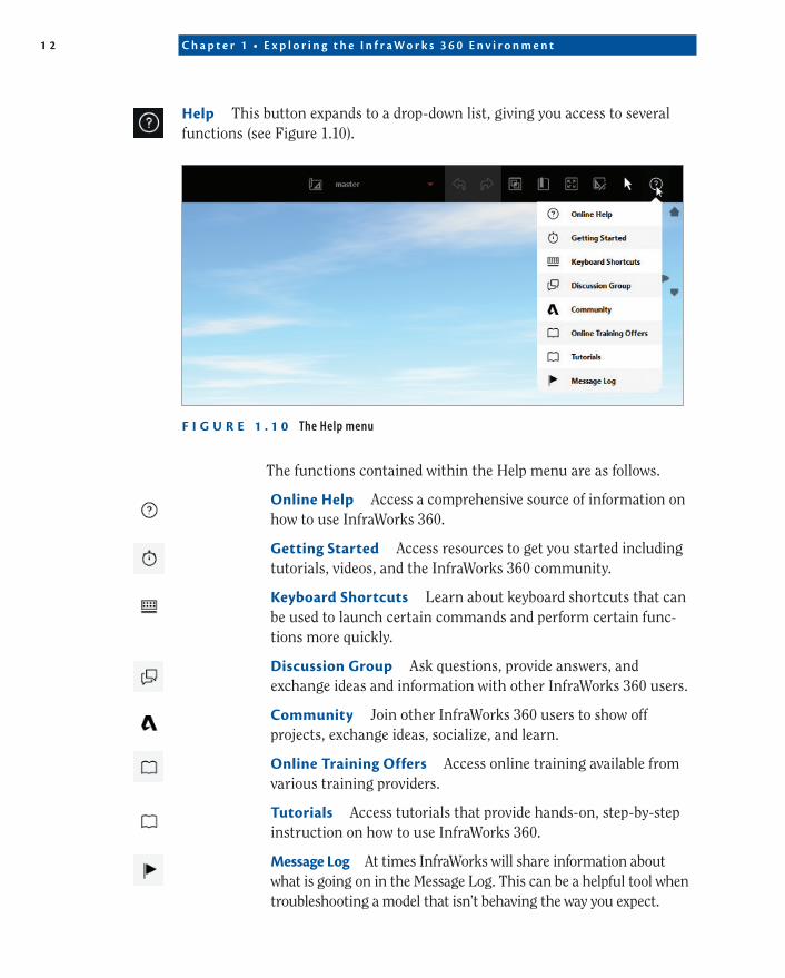
help This button expands to a drop-down list, giving you access to several functions (see Figure 1.10).
F I g U r e 1 . 1 0 The Help menu
The functions contained within the Help menu are as follows.
Online help Access a comprehensive source of information on how to use InfraWorks 360.
getting Started Access resources to get you started including tutorials, videos, and the InfraWorks 360 community.
Keyboard Shortcuts Learn about keyboard shortcuts that can be used to launch certain commands and perform certain func-tions more quickly.
Discussion group Ask questions, provide answers, and exchange ideas and information with other InfraWorks 360 users.
Community Join other InfraWorks 360 users to show off projects, exchange ideas, socialize, and learn.
Online training Offers Access online training available from various training providers.
tutorials Access tutorials that provide hands-on, step-by-step instruction on how to use InfraWorks 360.
Message Log At times InfraWorks will share information about what is going on in the Message Log. This can be a helpful tool when troubleshooting a model that isn’t behaving the way you expect.
G e t t i n g t o K n o w t h e I n f r a W o r k s U s e r I n t e r f a c e 1 3
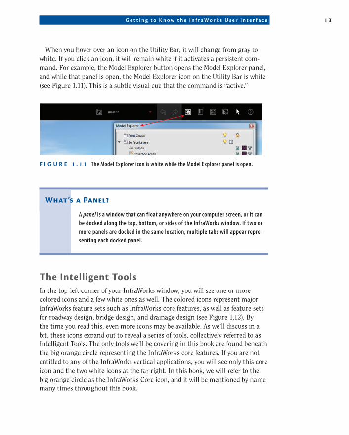
When you hover over an icon on the Utility Bar, it will change from gray to white. If you click an icon, it will remain white if it activates a persistent com-mand. For example, the Model Explorer button opens the Model Explorer panel, and while that panel is open, the Model Explorer icon on the Utility Bar is white (see Figure 1.11). This is a subtle visual cue that the command is “active.”
F I g U r e 1 . 1 1 The Model Explorer icon is white while the Model Explorer panel is open.
What’s a panel?
A panel is a window that can float anywhere on your computer screen, or it can be docked along the top, bottom, or sides of the InfraWorks window. If two or more panels are docked in the same location, multiple tabs will appear repre-senting each docked panel.
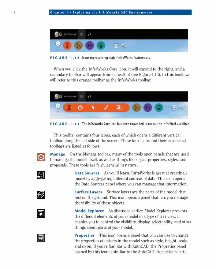
the Intelligent toolsIn the top-left corner of your InfraWorks window, you will see one or more colored icons and a few white ones as well. The colored icons represent major InfraWorks feature sets such as InfraWorks core features, as well as feature sets for roadway design, bridge design, and drainage design (see Figure 1.12). By the time you read this, even more icons may be available. As we’ll discuss in a bit, these icons expand out to reveal a series of tools, collectively referred to as Intelligent Tools. The only tools we’ll be covering in this book are found beneath the big orange circle representing the InfraWorks core features. If you are not entitled to any of the InfraWorks vertical applications, you will see only this core icon and the two white icons at the far right. In this book, we will refer to the big orange circle as the InfraWorks Core icon, and it will be mentioned by name many times throughout this book.
1 4 C h ap t e r 1 • E x p l o r i n g t h e I n f r aWo r k s 3 6 0 E n v i r o nmen t
F I g U r e 1 . 1 2 Icons representing major InfraWorks feature sets
When you click the InfraWorks Core icon, it will expand to the right, and a secondary toolbar will appear from beneath it (see Figure 1.13). In this book, we will refer to this orange toolbar as the InfraWorks toolbar.
F I g U r e 1 . 1 3 The InfraWorks Core icon has been expanded to reveal the InfraWorks toolbar.
This toolbar contains four icons, each of which opens a different vertical toolbar along the left side of the screen. These four icons and their associated toolbars are listed as follows:
Manage On the Manage toolbar, many of the tools open panels that are used to manage the model itself, as well as things like object properties, styles, and proposals. These tools are fairly general in nature.
Data Sources As you’ll learn, InfraWorks is great at creating a model by aggregating different sources of data. This icon opens the Data Sources panel where you can manage that information.
Surface Layers Surface layers are the parts of the model that rest on the ground. This icon opens a panel that lets you manage the visibility of these objects.
Model explorer As discussed earlier, Model Explorer presents the different elements of your model in a type of tree view. It enables you to control the visibility, display, selectability, and other things about parts of your model.
properties This icon opens a panel that you can use to change the properties of objects in the model such as style, height, scale, and so on. If you’re familiar with AutoCAD, the Properties panel opened by this icon is similar to the AutoCAD Properties palette.
G e t t i n g t o K n o w t h e I n f r a W o r k s U s e r I n t e r f a c e 1 5
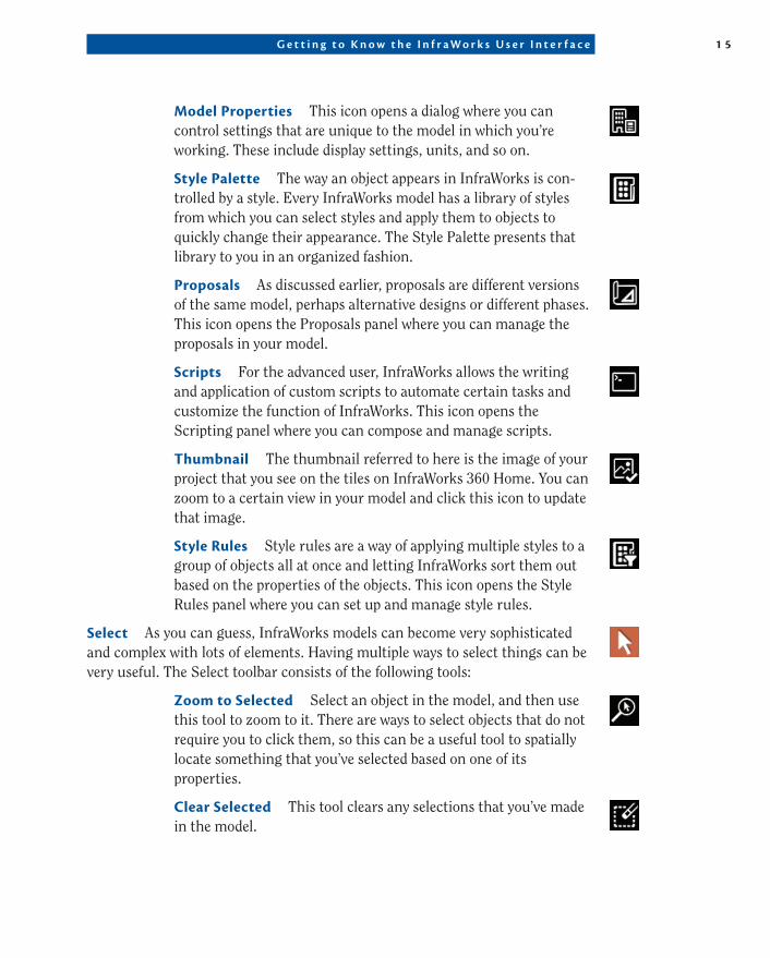
Model properties This icon opens a dialog where you can control settings that are unique to the model in which you’re working. These include display settings, units, and so on.
Style palette The way an object appears in InfraWorks is con-trolled by a style. Every InfraWorks model has a library of styles from which you can select styles and apply them to objects to quickly change their appearance. The Style Palette presents that library to you in an organized fashion.
proposals As discussed earlier, proposals are different versions of the same model, perhaps alternative designs or different phases. This icon opens the Proposals panel where you can manage the proposals in your model.
Scripts For the advanced user, InfraWorks allows the writing and application of custom scripts to automate certain tasks and customize the function of InfraWorks. This icon opens the Scripting panel where you can compose and manage scripts.
thumbnail The thumbnail referred to here is the image of your project that you see on the tiles on InfraWorks 360 Home. You can zoom to a certain view in your model and click this icon to update that image.
Style rules Style rules are a way of applying multiple styles to a group of objects all at once and letting InfraWorks sort them out based on the properties of the objects. This icon opens the Style Rules panel where you can set up and manage style rules.
Select As you can guess, InfraWorks models can become very sophisticated and complex with lots of elements. Having multiple ways to select things can be very useful. The Select toolbar consists of the following tools:
Zoom to Selected Select an object in the model, and then use this tool to zoom to it. There are ways to select objects that do not require you to click them, so this can be a useful tool to spatially locate something that you’ve selected based on one of its properties.
Clear Selected This tool clears any selections that you’ve made in the model.
1 6 C h ap t e r 1 • E x p l o r i n g t h e I n f r aWo r k s 3 6 0 E n v i r o nmen t
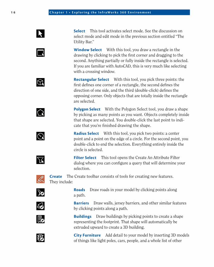
Select This tool activates select mode. See the discussion on select mode and edit mode in the previous section entitled “The Utility Bar.”
Window Select With this tool, you draw a rectangle in the drawing by clicking to pick the first corner and dragging to the second. Anything partially or fully inside the rectangle is selected. If you are familiar with AutoCAD, this is very much like selecting with a crossing window.
rectangular Select With this tool, you pick three points: the first defines one corner of a rectangle, the second defines the direction of one side, and the third (double-click) defines the opposing corner. Only objects that are totally inside the rectangle are selected.
polygon Select With the Polygon Select tool, you draw a shape by picking as many points as you want. Objects completely inside that shape are selected. You double-click the last point to indi-cate that you’re finished drawing the shape.
radius Select With this tool, you pick two points: a center point and a point on the edge of a circle. For the second point, you double-click to end the selection. Everything entirely inside the circle is selected.
Filter Select This tool opens the Create An Attribute Filter dialog where you can configure a query that will determine your selection.
Create The Create toolbar consists of tools for creating new features. They include:
roads Draw roads in your model by clicking points along a path.
Barriers Draw walls, jersey barriers, and other similar features by clicking points along a path.
Buildings Draw buildings by picking points to create a shape representing the footprint. That shape will automatically be extruded upward to create a 3D building.
City Furniture Add detail to your model by inserting 3D models of things like light poles, cars, people, and a whole list of other
G e t t i n g t o K n o w t h e I n f r a W o r k s U s e r I n t e r f a c e 1 7
items. Plus, you can include your own 3D models so just about anything can be added to your model as city furniture.
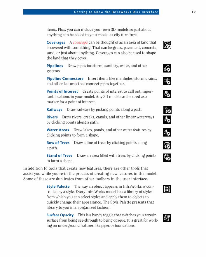
Coverages A coverage can be thought of as an area of land that is covered with something. That can be grass, pavement, concrete, sand, or just about anything. Coverages can also be used to shape the land that they cover.
pipelines Draw pipes for storm, sanitary, water, and other systems.
pipeline Connectors Insert items like manholes, storm drains, and other features that connect pipes together.
points of Interest Create points of interest to call out impor-tant locations in your model. Any 3D model can be used as a marker for a point of interest.
railways Draw railways by picking points along a path.
rivers Draw rivers, creeks, canals, and other linear waterways by clicking points along a path.
Water areas Draw lakes, ponds, and other water features by clicking points to form a shape.
row of trees Draw a line of trees by clicking points along a path.
Stand of trees Draw an area filled with trees by clicking points to form a shape.
In addition to tools that create new features, there are other tools that assist you while you’re in the process of creating new features in the model. Some of these are duplicates from other toolbars in the user interface.
Style palette The way an object appears in InfraWorks is con-trolled by a style. Every InfraWorks model has a library of styles from which you can select styles and apply them to objects to quickly change their appearance. The Style Palette presents that library to you in an organized fashion.
Surface Opacity This is a handy toggle that switches your terrain surface from being see-through to being opaque. It is great for work-ing on underground features like pipes or foundations.
1 8 C h ap t e r 1 • E x p l o r i n g t h e I n f r aWo r k s 3 6 0 E n v i r o nmen t
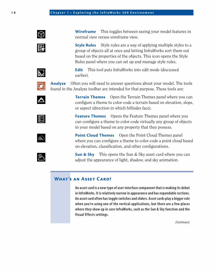
Wireframe This toggles between seeing your model features in normal view versus wireframe view.
Style rules Style rules are a way of applying multiple styles to a group of objects all at once and letting InfraWorks sort them out based on the properties of the objects. This icon opens the Style Rules panel where you can set up and manage style rules.
edit This tool puts InfraWorks into edit mode (discussed earlier).
analyze Often you will need to answer questions about your model. The tools found in the Analyze toolbar are intended for that purpose. These tools are:
terrain themes Open the Terrain Themes panel where you can configure a theme to color-code a terrain based on elevation, slope, or aspect (direction in which hillsides face).
Feature themes Opens the Feature Themes panel where you can configure a theme to color-code virtually any group of objects in your model based on any property that they possess.
point Cloud themes Open the Point Cloud Themes panel where you can configure a theme to color-code a point cloud based on elevation, classification, and other configurations.
Sun & Sky This opens the Sun & Sky asset card where you can adjust the appearance of light, shadow, and sky animation.
What’s an asset Card?
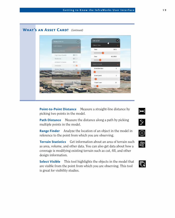
An asset card is a new type of user-interface component that is making its debut in InfraWorks. It is relatively narrow in appearance and has expandable sections. An asset card often has toggle switches and sliders. Asset cards play a bigger role when you’re using one of the vertical applications, but there are a few places where they show up in core InfraWorks, such as the Sun & Sky function and the Visual Effects settings.
(Continues)
G e t t i n g t o K n o w t h e I n f r a W o r k s U s e r I n t e r f a c e 1 9
point-to-point Distance Measure a straight-line distance by picking two points in the model.
path Distance Measure the distance along a path by picking multiple points in the model.
range Finder Analyze the location of an object in the model in reference to the point from which you are observing.
terrain Statistics Get information about an area of terrain such as area, volume, and other data. You can also get data about how a coverage is modifying existing terrain such as cut, fill, and other design information.
Select Visible This tool highlights the objects in the model that are visible from the point from which you are observing. This tool is great for visibility studies.
What’s an asset Card? (Continued)
2 0 C h ap t e r 1 • E x p l o r i n g t h e I n f r aWo r k s 3 6 0 E n v i r o nmen t
Filter Select Select objects by creating a query based on one or more properties.
What about Save?
Are you curious as to why there is no Save command in the user interface? InfraWorks saves automatically as you go, so there is no need for a Save command. Keep in mind, though, there is also no way to exit without saving—a trick that CAD users often use when they’ve done some work they’re not happy with and want to quickly go back to a prior state. Proposals, which you’ll learn about later, are a good way to create a “checkpoint” that you can go back to. There also is a Duplicate command, which you can use to make a copy of your model with a different name.
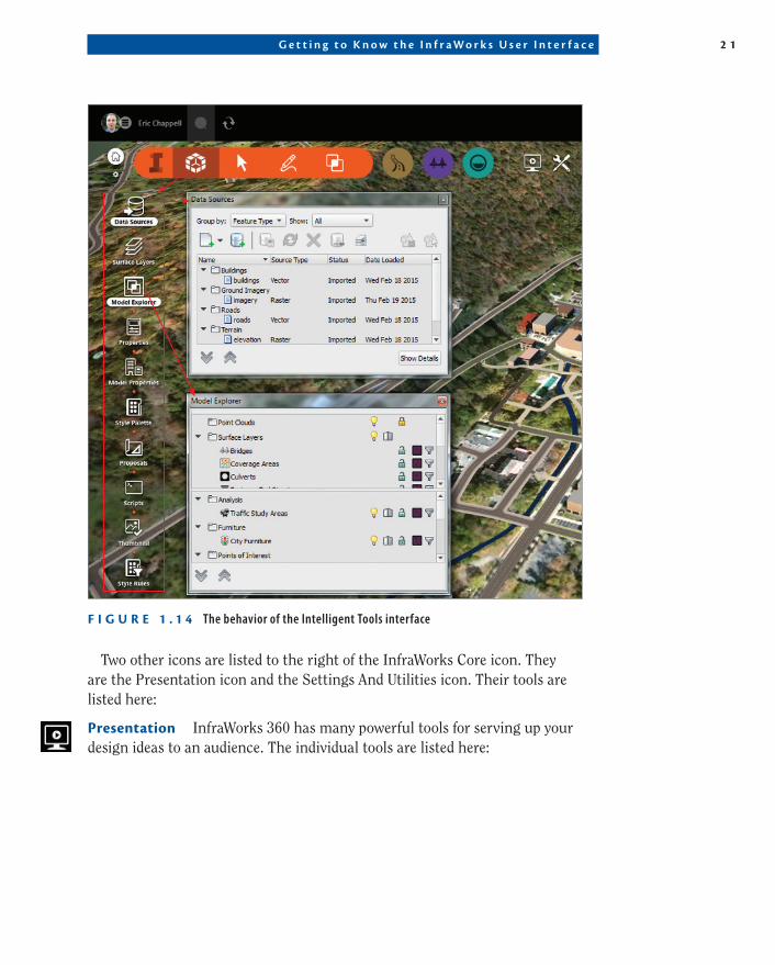
When you click an icon on the InfraWorks toolbar, the icon enlarges, and the background darkens—both indicating that the associated side toolbar is open. If you hide the InfraWorks toolbar by clicking the InfraWorks Core icon, that side toolbar remains active and will reappear if you click the InfraWorks Core icon again. With the side toolbar, if you click an item that launches a persistent user-interface component like a panel or dialog, the icon will enlarge, and the background of the command name will turn white—both indicating that the item that it launched is still open. In Figure 1.14, you can see that the Manage icon on the InfraWorks toolbar is enlarged, and its background is darkened. This is consistent with the Manage toolbar being open along the left side. In the Manage toolbar, you see that the Data Sources icon and the Model Explorer icon are both enlarged with white backgrounds behind the command names. This is indicative of the Model Explorer and Data Sources tabs being open.
G e t t i n g t o K n o w t h e I n f r a W o r k s U s e r I n t e r f a c e 2 1
F I g U r e 1 . 1 4 The behavior of the Intelligent Tools interface
Two other icons are listed to the right of the InfraWorks Core icon. They are the Presentation icon and the Settings And Utilities icon. Their tools are listed here:
presentation InfraWorks 360 has many powerful tools for serving up your design ideas to an audience. The individual tools are listed here:
2 2 C h ap t e r 1 • E x p l o r i n g t h e I n f r aWo r k s 3 6 0 E n v i r o nmen t
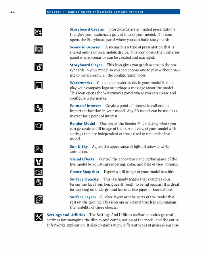
Storyboard Creator Storyboards are animated presentations that give your audience a guided tour of your model. This icon opens the Storyboard panel where you can build storyboards.
Scenario Browser A scenario is a type of presentation that is shared online or on a mobile device. This icon opens the Scenarios panel where scenarios can be created and managed.
Storyboard player This icon gives you quick access to the sto-ryboards in your model so you can choose one to play without hav-ing to work around all the configuration tools.
Watermarks You can add watermarks to your model that dis-play your company logo or perhaps a message about the model. This icon opens the Watermarks panel where you can create and configure watermarks.
points of Interest Create a point of interest to call out an important location in your model. Any 3D model can be used as a marker for a point of interest.
render Model This opens the Render Model dialog where you can generate a still image of the current view of your model with settings that are independent of those used to render the live model.
Sun & Sky Adjust the appearance of light, shadow, and sky animation.
Visual effects Control the appearance and performance of the live model by adjusting rendering, color, and field of view options.
Create Snapshot Export a still image of your model to a file.
Surface Opacity This is a handy toggle that switches your terrain surface from being see-through to being opaque. It is great for working on underground features like pipes or foundations.
Surface Layers Surface layers are the parts of the model that rest on the ground. This icon opens a panel that lets you manage the visibility of these objects.
Settings and Utilities The Settings And Utilities toolbar contains general settings for managing the display and configuration of the model and the entire InfraWorks application. It also contains many different types of general-purpose
G e t t i n g t o K n o w t h e I n f r a W o r k s U s e r I n t e r f a c e 2 3
tools for doing things such as exporting or duplicating the model, regenerating the model, creating and running scripts, updating the model thumbnail, and others. The tools contained in this toolbar include:
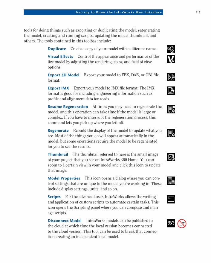
Duplicate Create a copy of your model with a different name.
Visual effects Control the appearance and performance of the live model by adjusting the rendering, color, and field of view options.
export 3D Model Export your model to FBX, DAE, or OBJ file format.
export IMX Export your model to IMX file format. The IMX format is good for including engineering information such as profile and alignment data for roads.
resume regeneration At times you may need to regenerate the model, and this operation can take time if the model is large or complex. If you have to interrupt the regeneration process, this command lets you pick up where you left off.
regenerate Rebuild the display of the model to update what you see. Most of the things you do will appear automatically in the model, but some operations require the model to be regenerated for you to see the results.
thumbnail The thumbnail referred to here is the small image of your project that you see on InfraWorks 360 Home. You can zoom to a certain view in your model and click this icon to update that image.
Model properties This icon opens a dialog where you can con-trol settings that are unique to the model you’re working in. These include display settings, units, and so on.
Scripts For the advanced user, InfraWorks allows the writing and application of custom scripts to automate certain tasks. This icon opens the Scripting panel where you can compose and man-age scripts.
Disconnect Model InfraWorks models can be published to the cloud at which time the local version becomes connected to the cloud version. This tool can be used to break that connec-tion creating an independent local model.
2 4 C h ap t e r 1 • E x p l o r i n g t h e I n f r aWo r k s 3 6 0 E n v i r o nmen t
application Options From here you can control program options such as units, 3D display configuration, and many others.
Message Log At times InfraWorks will share information about what is going on in the Message Log. This can be a helpful tool when troubleshooting a model that isn’t behaving the way you expect.
Data table The data table works in conjunction with Model Explorer. When you click a layer in Model Explorer, the data of the objects that occupy that layer will display on the Data Table panel.
Launch Screencast Use Autodesk Screencast to capture a video or a screenshot that can be used to teach others or provide infor-mation to someone who is supporting you.
and there’s More!
In addition to the base InfraWorks 360 software, Autodesk provides vertical applications that augment the InfraWorks feature set. For example, Roadway Design for InfraWorks 360 provides additional tools for highway design, analy-sis, and optimization. Also available are Bridge Design for InfraWorks 360 and Drainage Design for InfraWorks 360. Check the Autodesk website for additional information on these and other programs and services. This book is based on the InfraWorks 360 software with no vertical applications installed. There are Wiley books available on the vertical applications if you are interested in learn-ing more about them.
When you mouse over a command, a tooltip appears near your cursor to provide some additional information. This is a great feature to help you learn the user interface and assist you in choosing the right tools as you work. One final feature: At the bottom left of the screen you will see x-, y-, and z-coordi-nates that tell you the location and elevation of your cursor.
Intelligent tools Settings
You may have noticed a tiny, little gear icon to the left of the InfraWorks Core icon. If you click this icon, three settings will be revealed. The first setting (Labels) controls whether the names of the commands appear beneath the icons on the
(Continues)
G e t t i n g t o K n o w t h e I n f r a W o r k s U s e r I n t e r f a c e 2 5
toolbars. You can turn this off once you’ve worked with InfraWorks for a while and can identify the tools by their appearance alone. When turned on, the sec-ond setting (Hiding) will shift the toolbar to the left when you’re not using it so that it doesn’t obscure your view of the model quite so much. The third setting (Shade Hover) will produce shading behind the tools when your cursor is placed near or over them. This is to make the tools easier to see, especially when the area behind them happens to be very light.
exercise 1.2: explore the InfraWorks User InterfaceIf you are continuing from the previous exercise, you can skip to step 2. Otherwise, if you haven’t already done so, go to the book’s web page at www .sybex.com/go/infraworks360essentials2e and download the files for Chapter 1. Unzip the files to the correct location on your hard drive according to the instructions in the Introduction of this book.
1. If it is not already open, launch InfraWorks 360 or InfraWorks 360 LT.
2. On InfraWorks 360 Home, click Open and browse to C:\InfraWorks Essentials\Chapter 01\. Click Ch01 Tutorial (June 2015).sqlite and click Open.
3. Move your cursor over the InfraWorks Core icon, and notice how it becomes larger.
Notice also how a tooltip appears near your cursor.
4. Move the cursor back to the model, and notice how the InfraWorks Core icon returns to its original size.
5. Click the InfraWorks Core icon.Notice that the InfraWorks toolbar appears displaying the Manage,
Create, Select, and Analyze icons.
6. Click the Manage icon to reveal the Manage toolbar along the left side.
Intelligent tools Settings (Continued)
2 6 C h ap t e r 1 • E x p l o r i n g t h e I n f r aWo r k s 3 6 0 E n v i r o nmen t
7. Click the Model Explorer icon to open the Model Explorer panel.Notice that the Model Explorer icon is enlarged and the icon name
has a white background behind it. This indicates that the Model Explorer panel is open.
8. Click the Model Explorer icon again. The Model Explorer panel will close.
9. On the InfraWorks toolbar, click the Create icon to open the Create toolbar along the left side.
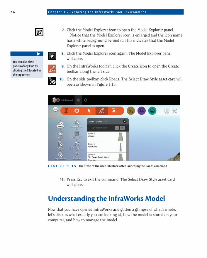
10. On the side toolbar, click Roads. The Select Draw Style asset card will open as shown in Figure 1.15.
F I g U r e 1 . 1 5 The state of the user interface after launching the Roads command
11. Press Esc to exit the command. The Select Draw Style asset card will close.
Understanding the InfraWorks ModelNow that you have opened InfraWorks and gotten a glimpse of what’s inside, let’s discuss what exactly you are looking at, how the model is stored on your computer, and how to manage the model.
▶
You can also close panels of any kind by clicking the X located in the top corner.
U n d e r s t a n d i n g t h e I n f r a W o r k s M o d e l 2 7
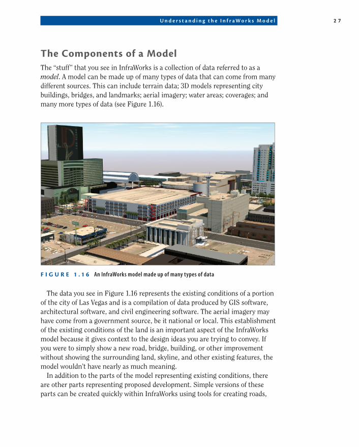
the Components of a ModelThe “stuff” that you see in InfraWorks is a collection of data referred to as a model. A model can be made up of many types of data that can come from many different sources. This can include terrain data; 3D models representing city buildings, bridges, and landmarks; aerial imagery; water areas; coverages; and many more types of data (see Figure 1.16).
F I g U r e 1 . 1 6 An InfraWorks model made up of many types of data
The data you see in Figure 1.16 represents the existing conditions of a portion of the city of Las Vegas and is a compilation of data produced by GIS software, architectural software, and civil engineering software. The aerial imagery may have come from a government source, be it national or local. This establishment of the existing conditions of the land is an important aspect of the InfraWorks model because it gives context to the design ideas you are trying to convey. If you were to simply show a new road, bridge, building, or other improvement without showing the surrounding land, skyline, and other existing features, the model wouldn’t have nearly as much meaning.
In addition to the parts of the model representing existing conditions, there are other parts representing proposed development. Simple versions of these parts can be created quickly within InfraWorks using tools for creating roads,
2 8 C h ap t e r 1 • E x p l o r i n g t h e I n f r aWo r k s 3 6 0 E n v i r o nmen t
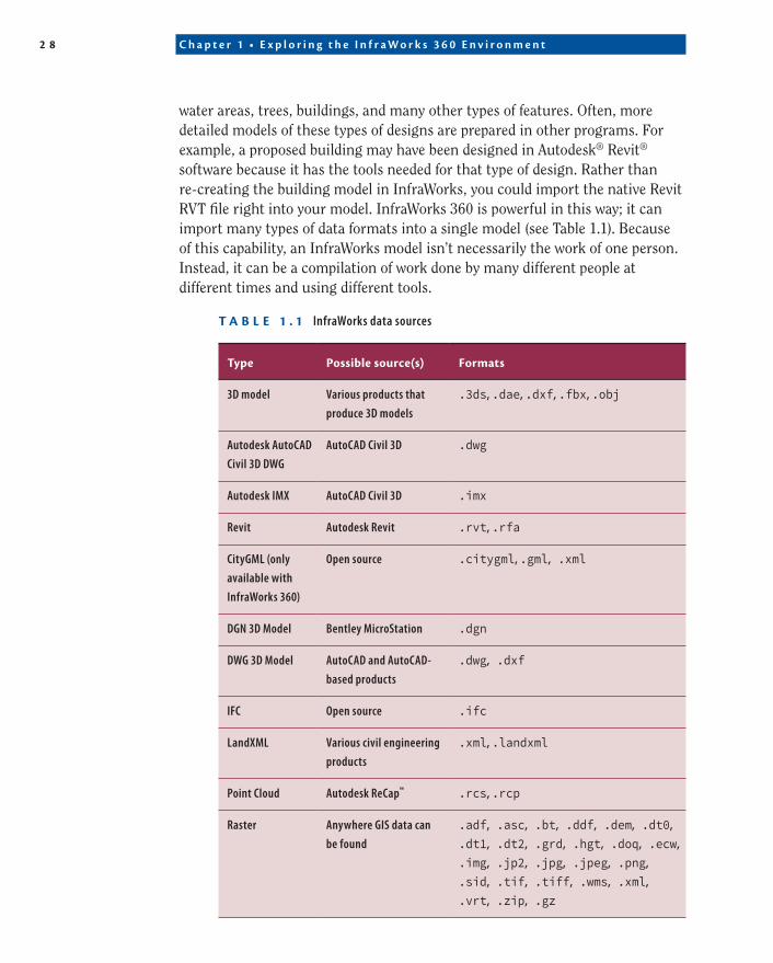
water areas, trees, buildings, and many other types of features. Often, more detailed models of these types of designs are prepared in other programs. For example, a proposed building may have been designed in Autodesk® Revit® software because it has the tools needed for that type of design. Rather than re-creating the building model in InfraWorks, you could import the native Revit RVT file right into your model. InfraWorks 360 is powerful in this way; it can import many types of data formats into a single model (see Table 1.1). Because of this capability, an InfraWorks model isn’t necessarily the work of one person. Instead, it can be a compilation of work done by many different people at different times and using different tools.
t a B L e 1 . 1 InfraWorks data sources
type possible source(s) Formats
3D model Various products that
produce 3D models
.3ds, .dae, .dxf, .fbx, .obj
Autodesk AutoCAD
Civil 3D DWG
AutoCAD Civil 3D .dwg
Autodesk IMX AutoCAD Civil 3D .imx
Revit Autodesk Revit .rvt, .rfa
CityGML (only
available with
InfraWorks 360)
Open source .citygml, .gml, .xml
DGN 3D Model Bentley MicroStation .dgn
DWG 3D Model AutoCAD and AutoCAD-
based products
.dwg, .dxf
IFC Open source .ifc
LandXML Various civil engineering
products
.xml, .landxml
Point Cloud Autodesk ReCap™ .rcs, .rcp
Raster Anywhere GIS data can
be found
.adf, .asc, .bt, .ddf, .dem, .dt0,
.dt1, .dt2, .grd, .hgt, .doq, .ecw,
.img, .jp2, .jpg, .jpeg, .png,
.sid, .tif, .tiff, .wms, .xml,
.vrt, .zip, .gz
U n d e r s t a n d i n g t h e I n f r a W o r k s M o d e l 2 9
type possible source(s) Formats
SDF Autodesk mapping
products
.sdf
SHP ESRI .shp
SQLite Various database sources .sdx, .sqlite, .db
SketchUp Trimble SketchUp .skp
Something else you should know about the data in an InfraWorks model is that it is georeferenced. This means the data is “aware” of where it belongs on the Earth. This is made possible through coordinate systems, something you’ll learn more about in the next chapter.
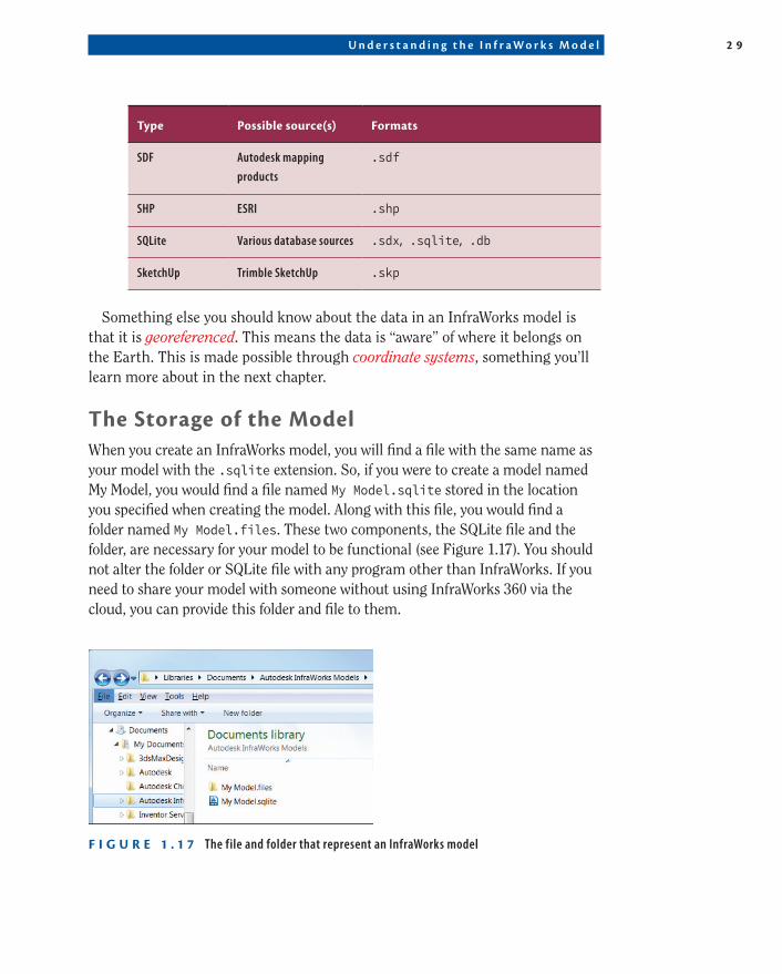
the Storage of the ModelWhen you create an InfraWorks model, you will find a file with the same name as your model with the .sqlite extension. So, if you were to create a model named My Model, you would find a file named My Model.sqlite stored in the location you specified when creating the model. Along with this file, you would find a folder named My Model.files. These two components, the SQLite file and the folder, are necessary for your model to be functional (see Figure 1.17). You should not alter the folder or SQLite file with any program other than InfraWorks. If you need to share your model with someone without using InfraWorks 360 via the cloud, you can provide this folder and file to them.
F I g U r e 1 . 1 7 The file and folder that represent an InfraWorks model
3 0 C h ap t e r 1 • E x p l o r i n g t h e I n f r aWo r k s 3 6 0 E n v i r o nmen t
Model explorerThe Model Explorer panel (shown previously in Figure 1.17) provides a way for you to view and access your data using a tree structure. You’ll find a series of folders on Model Explorer with each containing one or more data categories (also known as feature classes) beneath it. You will also find icons that control different aspects of the data.
Visibility This lightbulb icon can be used to turn the visibility of a feature class on or off.
Level of Detail (LOD) When this option is set to Adaptive LOD, InfraWorks will simplify the detail of the model as you zoom out. Depending on the makeup of your model, this might cause things to disappear when you are zoomed out to a certain point. When it is set to Maximum LOD, the maximum allowable detail will be displayed at all times, regardless of how far you’re zoomed in or out.
Selectable When a feature class is selectable, this icon appears as an open lock. A closed lock indicates that the feature class cannot be selected.
highlighting When this feature is turned on, the corresponding feature class will highlight in the model. You can specify the highlight color per item using the shortcut menu (covered a bit later).
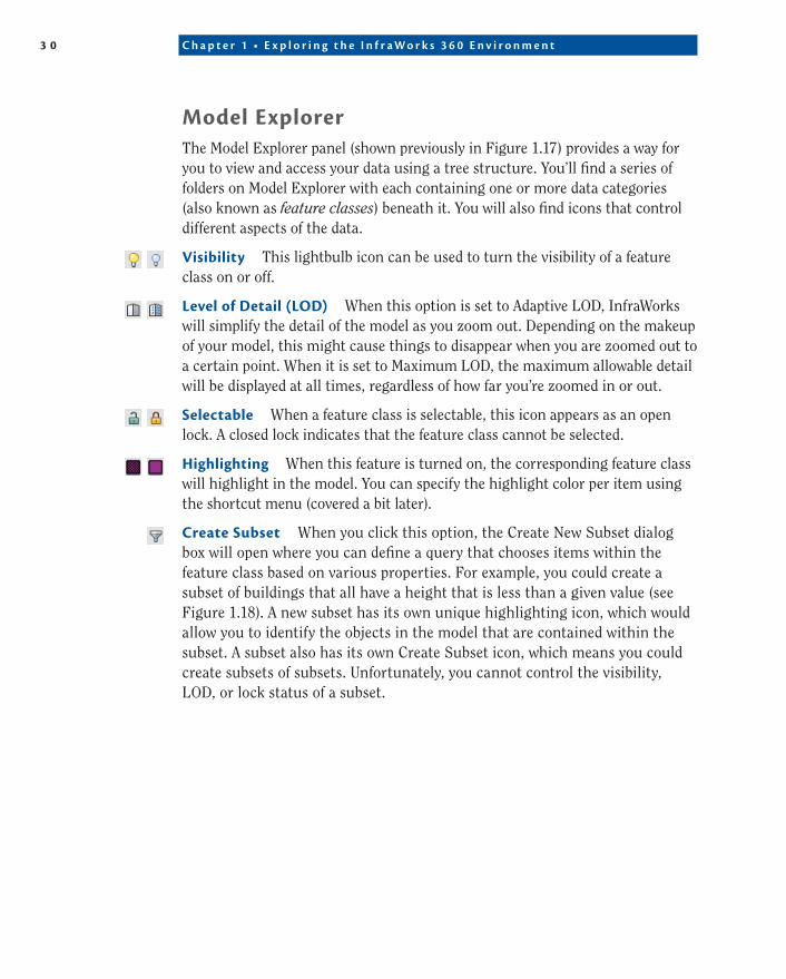
Create Subset When you click this option, the Create New Subset dialog box will open where you can define a query that chooses items within the feature class based on various properties. For example, you could create a subset of buildings that all have a height that is less than a given value (see Figure 1.18). A new subset has its own unique highlighting icon, which would allow you to identify the objects in the model that are contained within the subset. A subset also has its own Create Subset icon, which means you could create subsets of subsets. Unfortunately, you cannot control the visibility, LOD, or lock status of a subset.
U n d e r s t a n d i n g t h e I n f r a W o r k s M o d e l 3 1
F I g U r e 1 . 1 8 Creating a subset on Model Explorer
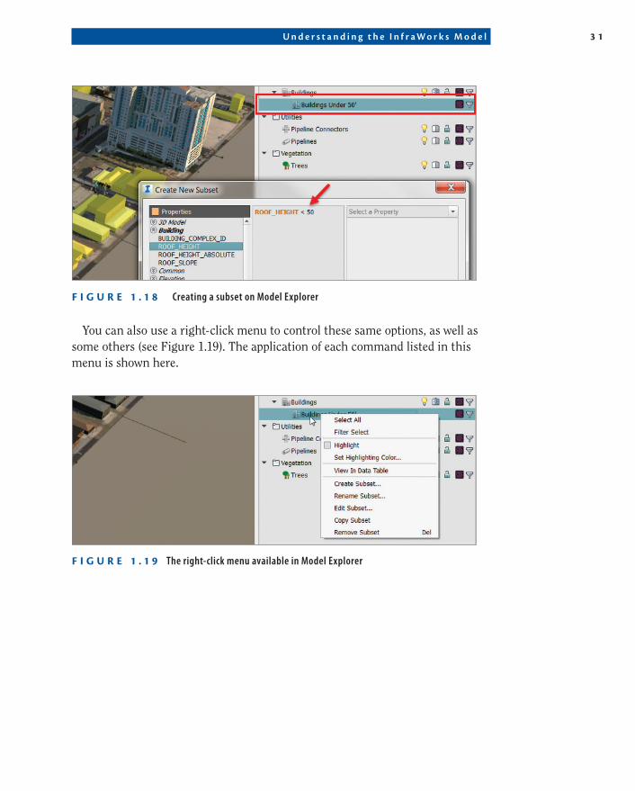
You can also use a right-click menu to control these same options, as well as some others (see Figure 1.19). The application of each command listed in this menu is shown here.
F I g U r e 1 . 1 9 The right-click menu available in Model Explorer
3 2 C h ap t e r 1 • E x p l o r i n g t h e I n f r aWo r k s 3 6 0 E n v i r o nmen t
Select all Click this option to select all members of a feature class or subset.
Filter Select Use this option to “create a subset on the fly” by creating a query that filters the data based on certain properties.
highlight Check and uncheck the box to turn highlighting on and off.
Set highlighting Color Clicking this option launches the standard Select Color dialog box, allowing you to specify a color for the feature class or subset.
View in Data table This will open the Data Table panel, which lists each item in the feature class or subset in tabular form. The table also includes the proper-ties associated with each item.
Create Subset Clicking this option is the same as clicking the Create Subset icon.
rename Subset (only for subsets) Use this option to change the name of the subset.
edit Subset (only for subsets) Click this option to open the Edit Subset Expression dialog box where you can change the parameters used to define the subset.
Copy Subset (only for subsets) Click this option to create a new subset directly beneath the selected subset. The new subset will have the same param-eters as the original.
Set Default tooltip When you hover over an object in your model, you have the option of displaying a tooltip for it. With this option, you can define the tooltip message for all of the items within the selected feature class (not available for subsets). Remember that you cannot see tooltips when you are in edit mode.
Set Default Link Click this option to set the default link for the all of the items within the selected feature class (not available for subsets). When an object has a link assigned to it, you can double-click that object to be redirected to the location (website, image file, etc.) referenced by the link.
exercise 1.3: Work with an InfraWorks ModelIf you are continuing from the previous exercise, you can skip to step 2. Otherwise, if you haven’t already done so, go to the book’s web page at www .sybex.com/go/infraworks360essentials2e and download the files for Chapter 1. Unzip the files to the correct location on your hard drive according to the instructions in the Introduction of this book.
U n d e r s t a n d i n g t h e I n f r a W o r k s M o d e l 3 3
1. If it is not already open, launch InfraWorks 360 or InfraWorks 360 LT.
2. On InfraWorks 360 Home, click Open and browse to C:\InfraWorks Essentials\Chapter 01\. Click Ch01 Fremont.sqlite and click Open.
3. Move your cursor to the upper-right corner of the InfraWorks window and click the Home icon when it appears.
This should orient your view so that you can see the model in southwest isometric view. This Home icon is part of the ViewCube. You will learn more about the ViewCube later in this chapter.
4. Roll the center wheel of your mouse backward to zoom out. Keep rolling backward until you can see North America and then finally the whole planet.
This is evidence of the georeferenced nature of the data with which you are working. It is located precisely where it should be on Earth. Later in this chapter, you will learn more about the use of the mouse to navigate the model.
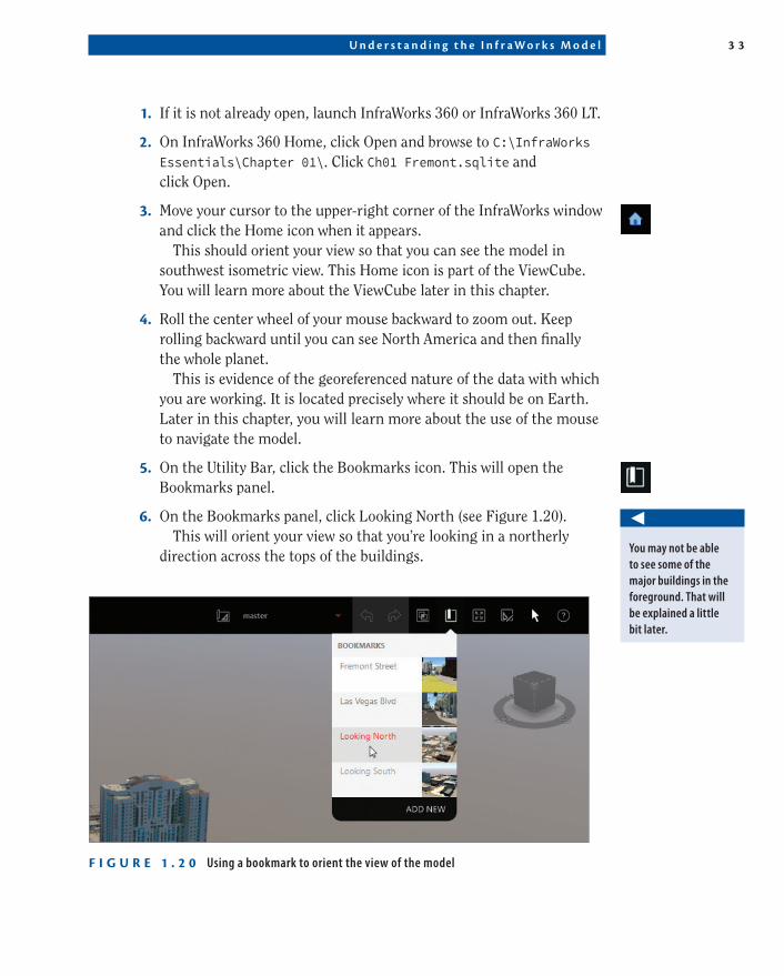
5. On the Utility Bar, click the Bookmarks icon. This will open the Bookmarks panel.
6. On the Bookmarks panel, click Looking North (see Figure 1.20).This will orient your view so that you’re looking in a northerly
direction across the tops of the buildings.
F I g U r e 1 . 2 0 Using a bookmark to orient the view of the model
◀
You may not be able to see some of the major buildings in the foreground. That will be explained a little bit later.
3 4 C h ap t e r 1 • E x p l o r i n g t h e I n f r aWo r k s 3 6 0 E n v i r o nmen t
7. If the Model Explorer panel is visible, skip to Step 10. Otherwise, if the InfraWorks toolbar is not visible, click the InfraWorks icon.
8. If the Manage toolbar is not visible, click the Manage icon on the InfraWorks toolbar.
9. If the Model Explorer panel is not visible, click the Model Explorer icon on the Manage toolbar.
The Model Explorer panel will open showing you a tree structure of object categories such as Bridges, Roads, City Furniture, Buildings, and Trees.
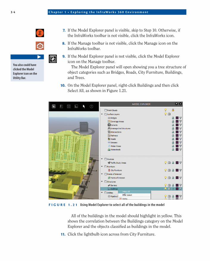
10. On the Model Explorer panel, right-click Buildings and then click Select All, as shown in Figure 1.21.
F I g U r e 1 . 2 1 Using Model Explorer to select all of the buildings in the model
All of the buildings in the model should highlight in yellow. This shows the correlation between the Buildings category on the Model Explorer and the objects classified as buildings in the model.
11. Click the lightbulb icon across from City Furniture.
▶
You also could have clicked the Model Explorer icon on the Utility Bar.
U n d e r s t a n d i n g t h e I n f r a W o r k s M o d e l 3 5
Items such as cars, power poles, and signs are no longer visible in the model.
12. Click the lightbulb icon across from City Furniture to turn it back on.The items that disappeared in step 11 are now visible again.
13. Click the lightbulb icon across from Trees to turn it off.All of the trees on the model disappear.
14. Click the lightbulb icon across from Trees to turn it back on.The trees are now visible again.
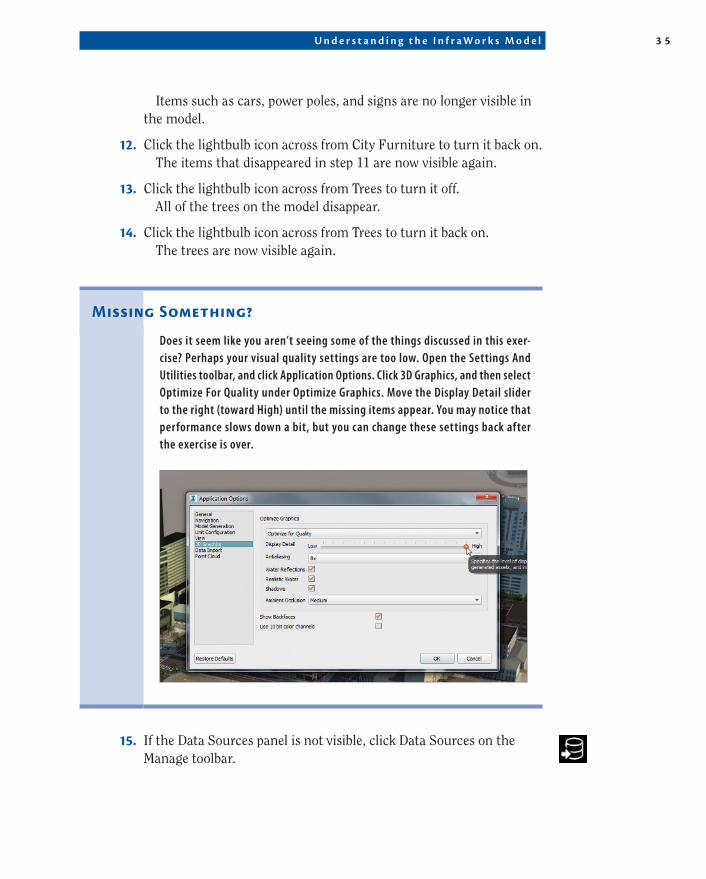
Missing Something?
Does it seem like you aren’t seeing some of the things discussed in this exer-cise? Perhaps your visual quality settings are too low. Open the Settings And Utilities toolbar, and click Application Options. Click 3D Graphics, and then select Optimize For Quality under Optimize Graphics. Move the Display Detail slider to the right (toward High) until the missing items appear. You may notice that performance slows down a bit, but you can change these settings back after the exercise is over.
15. If the Data Sources panel is not visible, click Data Sources on the Manage toolbar.
3 6 C h ap t e r 1 • E x p l o r i n g t h e I n f r aWo r k s 3 6 0 E n v i r o nmen t
The Data Sources panel will open as its own section or as a sec-ond tab within the window containing the Model Explorer panel. The Data Sources panel shows a listing of objects that have been imported into the model.
16. On the Data Sources panel, under Buildings, right-click The Ogden and then click Select Features.
The model of The Ogden highlights in yellow.
17. Repeat step 16 for The Fremont Street Experience and The D.Each of the respective models is highlighted when you select it in
the Data Sources panel.
Data Sources and Model explorer: What’s the Difference?
It might seem like the Data Sources panel and the Model Explorer panel kind of do the same thing. Here’s the difference: The Data Sources panel lists sources of data that have been imported into the model. This does not include things that have been created by you or another InfraWorks user by clicking one of the tools on the Create toolbar (Roads, Barriers, Buildings, etc.). The Model Explorer panel shows everything—things that have been imported or created. So the Model Explorer tab is more general in that it lists everything in the model, while the Data Sources panel only deals with things that were imported from “the outside.”
18. On the Manage toolbar, click Surface Layers.
19. Under Ground Imagery And Coverages, click the lightbulb icon next to 139-34-Image. Click Apply and then click OK.
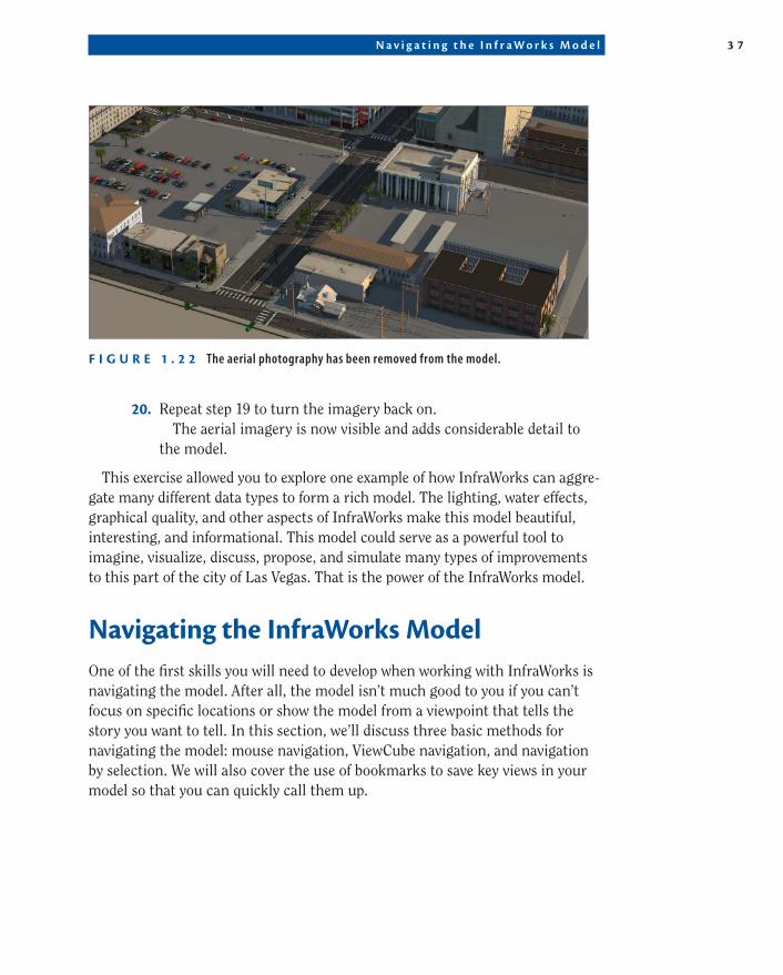
As you view the model, you can see that some of the detail that you were seeing was provided by aerial photos draped over the terrain. This is especially evident in the parking areas where you can no longer see the striping and some of the vehicles (see Figure 1.22).
▶
You may need to scroll down to find The Ogden.
N a v i g a t i n g t h e I n f r a W o r k s M o d e l 3 7
F I g U r e 1 . 2 2 The aerial photography has been removed from the model.
20. Repeat step 19 to turn the imagery back on.The aerial imagery is now visible and adds considerable detail to
the model.
This exercise allowed you to explore one example of how InfraWorks can aggre-gate many different data types to form a rich model. The lighting, water effects, graphical quality, and other aspects of InfraWorks make this model beautiful, interesting, and informational. This model could serve as a powerful tool to imagine, visualize, discuss, propose, and simulate many types of improvements to this part of the city of Las Vegas. That is the power of the InfraWorks model.
Navigating the InfraWorks ModelOne of the first skills you will need to develop when working with InfraWorks is navigating the model. After all, the model isn’t much good to you if you can’t focus on specific locations or show the model from a viewpoint that tells the story you want to tell. In this section, we’ll discuss three basic methods for navigating the model: mouse navigation, ViewCube navigation, and navigation by selection. We will also cover the use of bookmarks to save key views in your model so that you can quickly call them up.
3 8 C h ap t e r 1 • E x p l o r i n g t h e I n f r aWo r k s 3 6 0 E n v i r o nmen t
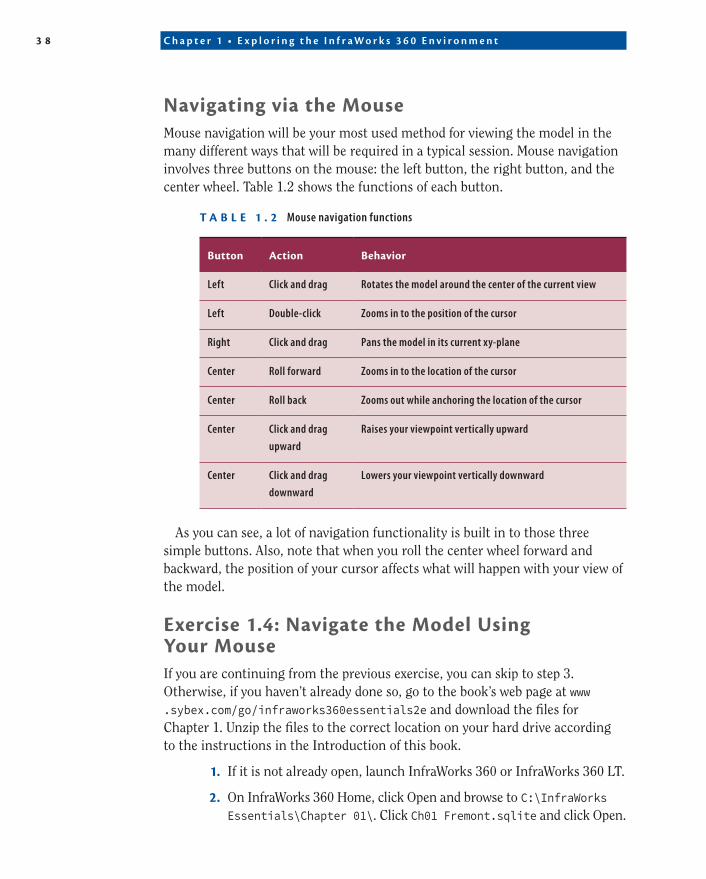
Navigating via the MouseMouse navigation will be your most used method for viewing the model in the many different ways that will be required in a typical session. Mouse navigation involves three buttons on the mouse: the left button, the right button, and the center wheel. Table 1.2 shows the functions of each button.
t a B L e 1 . 2 Mouse navigation functions
Button action Behavior
Left Click and drag Rotates the model around the center of the current view
Left Double-click Zooms in to the position of the cursor
Right Click and drag Pans the model in its current xy-plane
Center Roll forward Zooms in to the location of the cursor
Center Roll back Zooms out while anchoring the location of the cursor
Center Click and drag
upward
Raises your viewpoint vertically upward
Center Click and drag
downward
Lowers your viewpoint vertically downward
As you can see, a lot of navigation functionality is built in to those three simple buttons. Also, note that when you roll the center wheel forward and backward, the position of your cursor affects what will happen with your view of the model.
exercise 1.4: Navigate the Model Using Your MouseIf you are continuing from the previous exercise, you can skip to step 3. Otherwise, if you haven’t already done so, go to the book’s web page at www .sybex.com/go/infraworks360essentials2e and download the files for Chapter 1. Unzip the files to the correct location on your hard drive according to the instructions in the Introduction of this book.
1. If it is not already open, launch InfraWorks 360 or InfraWorks 360 LT.
2. On InfraWorks 360 Home, click Open and browse to C:\InfraWorks Essentials\Chapter 01\. Click Ch01 Fremont.sqlite and click Open.
N a v i g a t i n g t h e I n f r a W o r k s M o d e l 3 9
3. If the Bookmarks panel is not visible, click Bookmarks on the Utility Bar.
4. On the Bookmarks panel, click Looking South.
5. Click the left mouse button and drag it left and right.Notice how the model rotates around a point near the main
entrance of Neonopolis.
6. Restore the Looking South bookmark to reset the view.
7. Click the left mouse button and drag upward and downward.Notice how the model rotates away from you when you drag
upward and toward you when you drag downward. Again, the model rotates around the same point near the main entrance of Neonopolis.
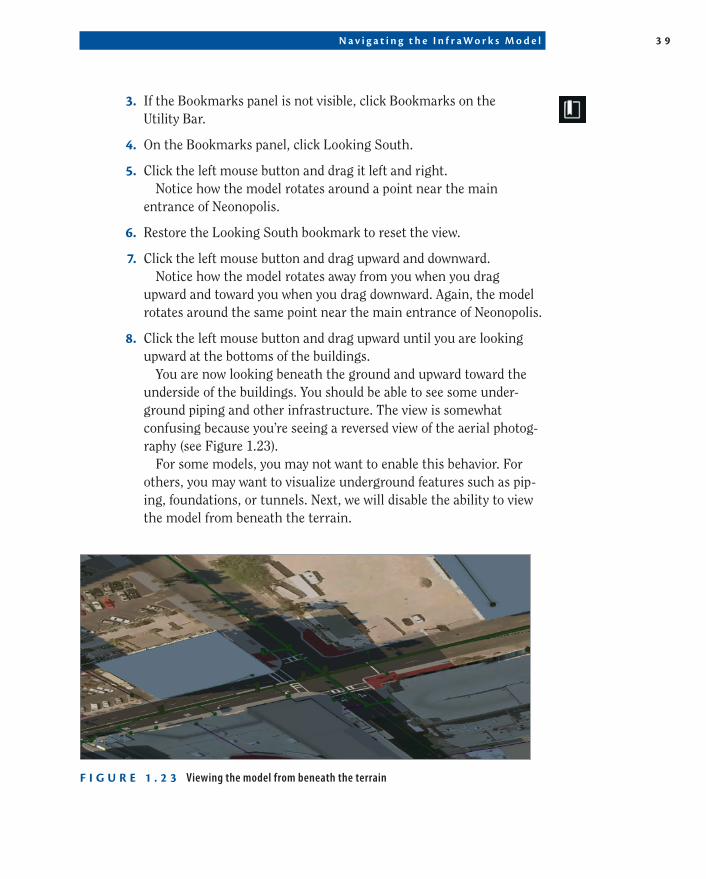
8. Click the left mouse button and drag upward until you are looking upward at the bottoms of the buildings.
You are now looking beneath the ground and upward toward the underside of the buildings. You should be able to see some under-ground piping and other infrastructure. The view is somewhat confusing because you’re seeing a reversed view of the aerial photog-raphy (see Figure 1.23).
For some models, you may not want to enable this behavior. For others, you may want to visualize underground features such as pip-ing, foundations, or tunnels. Next, we will disable the ability to view the model from beneath the terrain.
F I g U r e 1 . 2 3 Viewing the model from beneath the terrain
4 0 C h ap t e r 1 • E x p l o r i n g t h e I n f r aWo r k s 3 6 0 E n v i r o nmen t
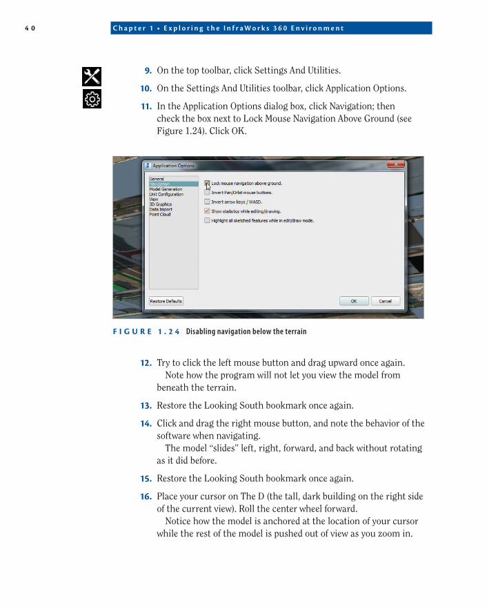
9. On the top toolbar, click Settings And Utilities.
10. On the Settings And Utilities toolbar, click Application Options.
11. In the Application Options dialog box, click Navigation; then check the box next to Lock Mouse Navigation Above Ground (see Figure 1.24). Click OK.
F I g U r e 1 . 2 4 Disabling navigation below the terrain
12. Try to click the left mouse button and drag upward once again.Note how the program will not let you view the model from
beneath the terrain.
13. Restore the Looking South bookmark once again.
14. Click and drag the right mouse button, and note the behavior of the software when navigating.
The model “slides” left, right, forward, and back without rotating as it did before.
15. Restore the Looking South bookmark once again.
16. Place your cursor on The D (the tall, dark building on the right side of the current view). Roll the center wheel forward.
Notice how the model is anchored at the location of your cursor while the rest of the model is pushed out of view as you zoom in.
N a v i g a t i n g t h e I n f r a W o r k s M o d e l 4 1
17. Restore the Looking South bookmark.
18. Place your cursor on The Ogden (the large tan and blue building on the left side of your current view), and note how that point is anchored while zooming in.
19. Experiment with placing your cursor in different locations while zooming in and out.
20. Restore the Fremont Street bookmark.
21. Click and hold the center wheel while dragging upward.Note the behavior of the model while you do this. Your viewpoint is
raised upward as you drag.
22. Click and hold the center wheel while dragging downward, and note that your viewpoint is lowered.
Navigation by Keyboard
There are also a number of keyboard shortcuts that you can use to navigate the InfraWorks model. You can find information on these by clicking the Help icon and then clicking Keyboard Shortcuts.
Navigating by ViewCubeThe ViewCube is another great way to navigate your InfraWorks model. Perhaps you’re already familiar with the ViewCube, having been introduced to it in another Autodesk product. Let’s assume you haven’t, however, and talk about the details of using the ViewCube.
You’ll find the ViewCube in the upper-right corner of the InfraWorks window. The ViewCube is a schematic representation of the current orientation of your model, as well as an interactive part of the user interface that you can manipu-late to change the view of your model. The ViewCube has 26 defined areas that you can click to set the view orientation: 8 corners, 12 edges, and 6 faces. For example, if you click the top face, you will view the model from the top down; if you click the top southwest corner, you will view the model in an isometric view looking down toward the northeast (see Figure 1.25); and so on. You can
4 2 C h ap t e r 1 • E x p l o r i n g t h e I n f r aWo r k s 3 6 0 E n v i r o nmen t
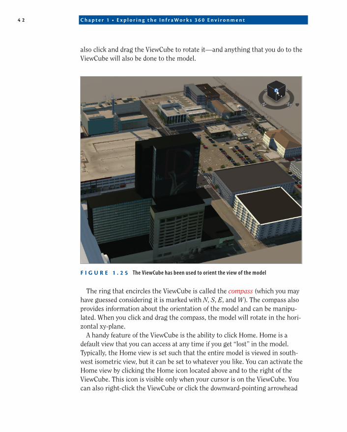
also click and drag the ViewCube to rotate it—and anything that you do to the ViewCube will also be done to the model.
F I g U r e 1 . 2 5 The ViewCube has been used to orient the view of the model
The ring that encircles the ViewCube is called the compass (which you may have guessed considering it is marked with N, S, E, and W). The compass also provides information about the orientation of the model and can be manipu-lated. When you click and drag the compass, the model will rotate in the hori-zontal xy-plane.
A handy feature of the ViewCube is the ability to click Home. Home is a default view that you can access at any time if you get “lost” in the model. Typically, the Home view is set such that the entire model is viewed in south-west isometric view, but it can be set to whatever you like. You can activate the Home view by clicking the Home icon located above and to the right of the ViewCube. This icon is visible only when your cursor is on the ViewCube. You can also right-click the ViewCube or click the downward-pointing arrowhead
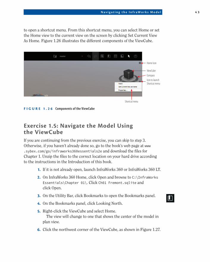
N a v i g a t i n g t h e I n f r a W o r k s M o d e l 4 3
to open a shortcut menu. From this shortcut menu, you can select Home or set the Home view to the current view on the screen by clicking Set Current View As Home. Figure 1.26 illustrates the different components of the ViewCube.
Shortcut menu
Home Icon
ViewCube
Compass
Icon to launchShortcut menu
F I g U r e 1 . 2 6 Components of the ViewCube
exercise 1.5: Navigate the Model Using the ViewCubeIf you are continuing from the previous exercise, you can skip to step 3. Otherwise, if you haven’t already done so, go to the book’s web page at www .sybex.com/go/infraworks360essentials2e and download the files for Chapter 1. Unzip the files to the correct location on your hard drive according to the instructions in the Introduction of this book.
1. If it is not already open, launch InfraWorks 360 or InfraWorks 360 LT.
2. On InfraWorks 360 Home, click Open and browse to C:\InfraWorks Essentials\Chapter 01\. Click Ch01 Fremont.sqlite and click Open.
3. On the Utility Bar, click Bookmarks to open the Bookmarks panel.
4. On the Bookmarks panel, click Looking North.
5. Right-click the ViewCube and select Home.The view will change to one that shows the center of the model in
plan view.
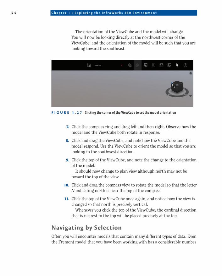
6. Click the northwest corner of the ViewCube, as shown in Figure 1.27.
4 4 C h ap t e r 1 • E x p l o r i n g t h e I n f r aWo r k s 3 6 0 E n v i r o nmen t
The orientation of the ViewCube and the model will change. You will now be looking directly at the northwest corner of the ViewCube, and the orientation of the model will be such that you are looking toward the southeast.
F I g U r e 1 . 2 7 Clicking the corner of the ViewCube to set the model orientation
7. Click the compass ring and drag left and then right. Observe how the model and the ViewCube both rotate in response.
8. Click and drag the ViewCube, and note how the ViewCube and the model respond. Use the ViewCube to orient the model so that you are looking in the southwest direction.
9. Click the top of the ViewCube, and note the change to the orientation of the model.
It should now change to plan view although north may not be toward the top of the view.
10. Click and drag the compass view to rotate the model so that the letter N indicating north is near the top of the compass.
11. Click the top of the ViewCube once again, and notice how the view is changed so that north is precisely vertical.
Whenever you click the top of the ViewCube, the cardinal direction that is nearest to the top will be placed precisely at the top.
Navigating by SelectionOften you will encounter models that contain many different types of data. Even the Fremont model that you have been working with has a considerable number
N a v i g a t i n g t h e I n f r a W o r k s M o d e l 4 5
of data sources and many parts that make up the model. In these cases, you will find it useful to be able to select different parts of the model and change your view orientation based on those selections. InfraWorks 360 contains several tools that enable you to navigate the model by selection.
One of the most helpful techniques is to first select an object within the Data Sources panel or Model Viewer panel and then use the Zoom To Selected tool on the Select toolbar to zoom to that object. As you might guess, this is especially helpful when you have a large complex model and need to simply locate one of its components.
exercise 1.6: Navigate by SelectionIf you are continuing from the previous exercise, you can skip to step 3. Otherwise, if you haven’t already done so, go to the book’s web page at www .sybex.com/go/infraworks360essentials2e and download the files for Chapter 1. Unzip the files to the correct location on your hard drive according to the instructions in the Introduction of this book.
1. If it is not already open, launch InfraWorks 360 or InfraWorks 360 LT.
2. On InfraWorks 360 Home, click Open and browse to C:\InfraWorks Essentials\Chapter 01\. Click Ch01 Fremont.sqlite and click Open.
3. On the Utility Bar, click Bookmarks to open the Bookmarks panel.
4. On the Bookmarks panel, click Looking North.
5. If the Data Sources panel is not visible, click Data Sources on the Manage toolbar.
6. On the Data Sources panel, under Buildings, right-click Cowboy Sign and click Select Features.
7. On the InfraWorks Core toolbar, click the Select icon to open the Select toolbar.
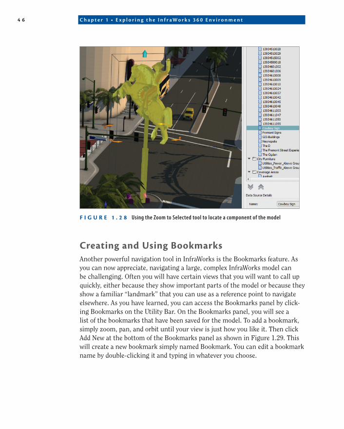
8. On the Select toolbar, click Zoom To Selected. Roll the mouse wheel back a bit to zoom out to a point where the cowboy sign is visible (see Figure 1.28).
4 6 C h ap t e r 1 • E x p l o r i n g t h e I n f r aWo r k s 3 6 0 E n v i r o nmen t
F I g U r e 1 . 2 8 Using the Zoom to Selected tool to locate a component of the model
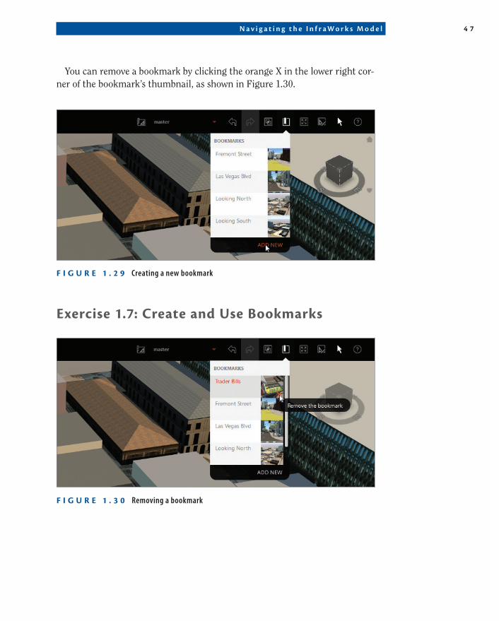
Creating and Using BookmarksAnother powerful navigation tool in InfraWorks is the Bookmarks feature. As you can now appreciate, navigating a large, complex InfraWorks model can be challenging. Often you will have certain views that you will want to call up quickly, either because they show important parts of the model or because they show a familiar “landmark” that you can use as a reference point to navigate elsewhere. As you have learned, you can access the Bookmarks panel by click-ing Bookmarks on the Utility Bar. On the Bookmarks panel, you will see a list of the bookmarks that have been saved for the model. To add a bookmark, simply zoom, pan, and orbit until your view is just how you like it. Then click Add New at the bottom of the Bookmarks panel as shown in Figure 1.29. This will create a new bookmark simply named Bookmark. You can edit a bookmark name by double-clicking it and typing in whatever you choose.
N a v i g a t i n g t h e I n f r a W o r k s M o d e l 4 7
You can remove a bookmark by clicking the orange X in the lower right cor-ner of the bookmark’s thumbnail, as shown in Figure 1.30.
F I g U r e 1 . 2 9 Creating a new bookmark
exercise 1.7: Create and Use Bookmarks
F I g U r e 1 . 3 0 Removing a bookmark
4 8 C h ap t e r 1 • E x p l o r i n g t h e I n f r aWo r k s 3 6 0 E n v i r o nmen t
If you are continuing from the previous exercise, you can skip to step 3. Otherwise, if you haven’t already done so, go to the book’s web page at www .sybex.com/go/infraworks360essentials2e and download the files for Chapter 1. Unzip the files to the correct location on your hard drive according to the instructions in the Introduction of this book.
1. If it is not already open, launch InfraWorks 360 or InfraWorks 360 LT.
2. On InfraWorks 360 Home, click Open and browse to C:\InfraWorks Essentials\Chapter 01\. Click Ch01 Fremont.sqlite and click Open.
3. Right-click the ViewCube and select Home.
4. If the Data Sources panel is not visible, click Data Sources on the Manage toolbar.
5. On the Data Sources panel, under Landmarks, right-click Trader Bills and click Select Features.
6. On the Select toolbar, click Zoom To Selected.
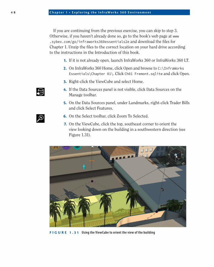
7. On the ViewCube, click the top, southeast corner to orient the view looking down on the building in a southwestern direction (see Figure 1.31).
F I g U r e 1 . 3 1 Using the ViewCube to orient the view of the building
N o w Yo u K n o w 4 9
8. Click Bookmarks on the Utility Bar, and then click Add Bookmark.
9. Type Trader Bills as shown previously in Figure 1.32. Press Enter.
10. Press Esc to clear the selection of the Trader Bills model.
11. Right-click the ViewCube and select Home. Your view will change to one that shows the center of the model in plan view.
12. Click Bookmarks and then click Trader Bills. You should return to a view similar to the one you saw when you created the bookmark.
Now You Know
If you feel like the InfraWorks environment seems new and maybe even somewhat foreign, you’re not alone. InfraWorks has existed for only a short time and is essentially new—and exciting—to everyone. After seeing the beauty and detail of the Fremont model, hopefully, you are impressed with what InfraWorks can do and how effectively it can simulate a real place on Earth. Imagine how effective it can be in planning, visualizing, and discussing proposed developments of land and infrastructure.
In addition to having a new appreciation for the InfraWorks environment, you now know how to enter the world of an InfraWorks model using InfraWorks 360 Home. You also know how to effectively navigate that environment using your mouse, the ViewCube, and some handy selection tools. You are also able to leverage bookmarks to save those important views in your model.
Not only can you navigate a model, you can also navigate the InfraWorks user interface. You’ve been given an overview of every one of the Intelligent Tools and have been introduced to user interface components such as the utility bar, panels, and asset cards.
Now that you know how to access and navigate someone else’s world, you’re ready to begin learning how to create an InfraWorks world of your own.