Embed Size (px)
Citation preview
RECOMMENDED DEPLOYMENT PRACTICES
F5 BIG-IP and FireEye NX: Using the F5 iApps Template for SSL Intercept
Srikanth T. R.Solution Architect, Business Development
2
RECOMMENDED PRACTICES
F5 BIG-IP and FireEye NX Deployment Guide Using the F5 iApps Template for SSL Intercept
ContentsIntroduction 3
The Integrated F5 and FireEye Solution 4
SSL intercept: Gaining visibility into encrypted traffic 4
Deployment Planning 5
Sizing 5
License components 6
Initial Setup 10
Configure URL filtering 10
Configure data groups for SSL bypass 11
Import the iApps template 11
Configuration: SSL Visibility Solution with Two BIG-IP Systems 12
Traffic flow 12
Ingress BIG-IP configuration 13
Configuration steps: Egress BIG-IP configuration 19
Configuration: SSL Visibility Solution with One BIG-IP System 21
Traffic flow 22
Configuration steps 24
Clone Pools to Copy Traffic to FireEye NX Devices Deployed in TAP Mode 35
Traffic flow 35
Deployment steps 36
Advanced Configuration 40
Inspection bypass 40
iRule configuration 41
SSLv3 cipher suites 44
External Health Monitors 45
Testing the Solution 46
RECOMMENDED DEPLOYMENT PRACTICES
F5 BIG-IP and FireEye NX: Using the F5 iApps Template for SSL Intercept
3
IntroductionSSL/TLS has been widely adopted by organizations to secure IP communications, and its
use is increasing. While SSL provides data privacy and secure communication, it also
creates challenges to components of the security infrastructure in place to inspect the
encrypted traffic. In short, the encrypted communications can’t be seen like clear text and
thus are passed through without inspection, rendering any defense-in-depth architecture
ineffective. This creates significant risks to businesses: What if attackers are hiding malware
inside the encrypted traffic?
Security devices today such as intrusion prevention systems (IPSs) and next-generation
firewalls (NGFWs) lack the processing power to easily decrypt SSL/TLS traffic.
This performance concern becomes even more challenging with the demands of 2048-bit
certificates. The processing capacity of these security devices is further reduced when they
are deployed in inline mode, as in that case they not only take the interesting traffic—that is,
any wire traffic that needs to be inspected—but all of the wire traffic. Alternatively, deploying
these devices in monitoring mode conserves system resources but comes at a cost: only
alerting administrators to the threats, not blocking them.
The integrated F5 and FireEye solution solves these two SSL/TSL challenges with an
advanced threat protection system that enables organizations to decrypt encrypted traffic
within the enterprise boundaries, thus gaining visibility into that encrypted communication
to identify and block zero-day web exploits. In addition, only the interesting traffic is
decrypted for inspection, not all of the wire traffic, conserving the processing resources of
the inspecting device.
This guide provides an overview of the solution, describes different deployment modes,
suggests recommended practices, and offers guidance for how to handle enforcement of
corporate Internet use policies.
RECOMMENDED DEPLOYMENT PRACTICES
F5 BIG-IP and FireEye NX: Using the F5 iApps Template for SSL Intercept
4
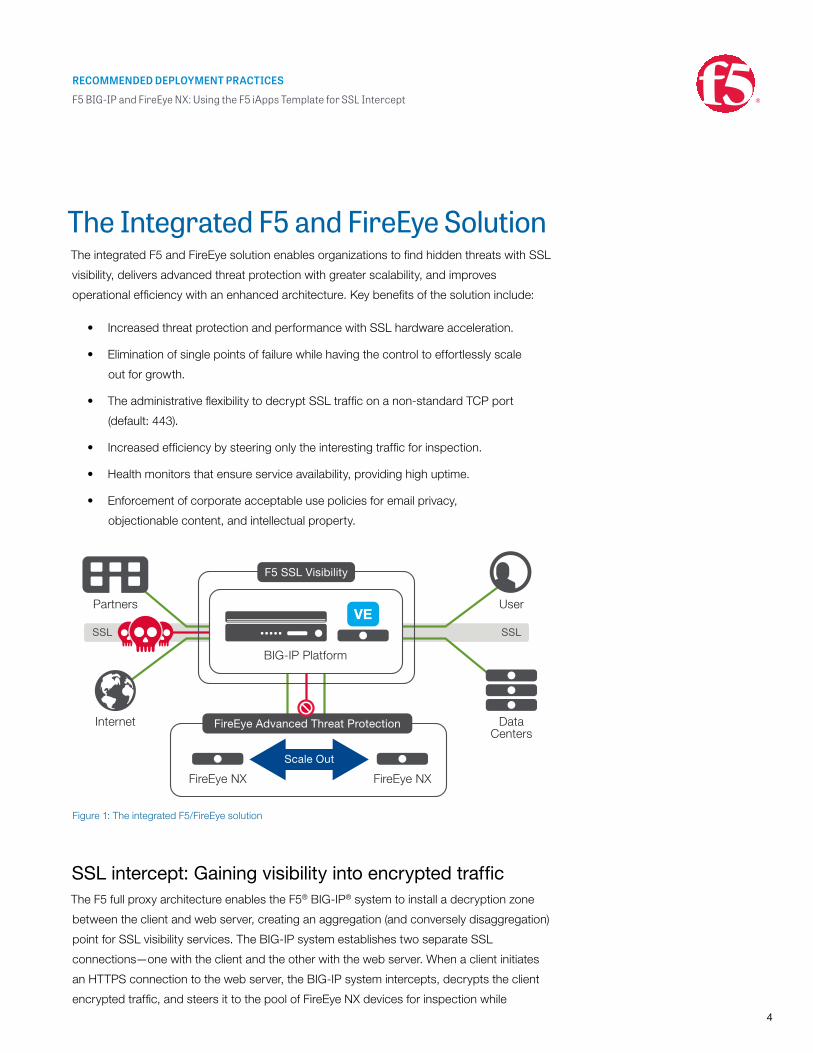
The Integrated F5 and FireEye Solution The integrated F5 and FireEye solution enables organizations to find hidden threats with SSL
visibility, delivers advanced threat protection with greater scalability, and improves
operational efficiency with an enhanced architecture. Key benefits of the solution include:
• Increased threat protection and performance with SSL hardware acceleration.
• Elimination of single points of failure while having the control to effortlessly scale
out for growth.
• The administrative flexibility to decrypt SSL traffic on a non-standard TCP port
(default: 443).
• Increased efficiency by steering only the interesting traffic for inspection.
• Health monitors that ensure service availability, providing high uptime.
• Enforcement of corporate acceptable use policies for email privacy,
objectionable content, and intellectual property.
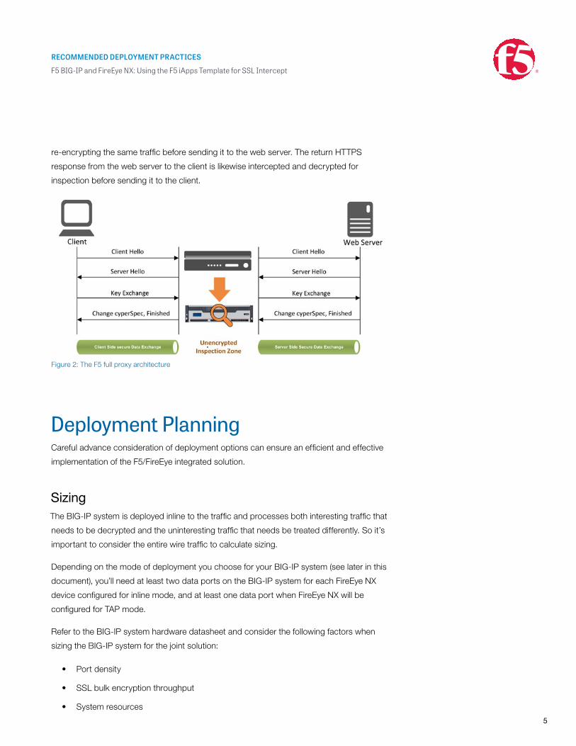
SSL intercept: Gaining visibility into encrypted trafficThe F5 full proxy architecture enables the F5® BIG-IP® system to install a decryption zone
between the client and web server, creating an aggregation (and conversely disaggregation)
point for SSL visibility services. The BIG-IP system establishes two separate SSL
connections—one with the client and the other with the web server. When a client initiates
an HTTPS connection to the web server, the BIG-IP system intercepts, decrypts the client
encrypted traffic, and steers it to the pool of FireEye NX devices for inspection while
FireEye Advanced Threat Protection
F5 SSL Visibility
Internet
Partners
BIG-IP Platform
User
DataCenters
FireEye NX FireEye NX
Scale Out
Figure 1: The integrated F5/FireEye solution
RECOMMENDED DEPLOYMENT PRACTICES
F5 BIG-IP and FireEye NX: Using the F5 iApps Template for SSL Intercept
5
re-encrypting the same traffic before sending it to the web server. The return HTTPS
response from the web server to the client is likewise intercepted and decrypted for
inspection before sending it to the client.
Deployment PlanningCareful advance consideration of deployment options can ensure an efficient and effective
implementation of the F5/FireEye integrated solution.
SizingThe BIG-IP system is deployed inline to the traffic and processes both interesting traffic that
needs to be decrypted and the uninteresting traffic that needs be treated differently. So it’s
important to consider the entire wire traffic to calculate sizing.
Depending on the mode of deployment you choose for your BIG-IP system (see later in this
document), you’ll need at least two data ports on the BIG-IP system for each FireEye NX
device configured for inline mode, and at least one data port when FireEye NX will be
configured for TAP mode.
Refer to the BIG-IP system hardware datasheet and consider the following factors when
sizing the BIG-IP system for the joint solution:
• Port density
• SSL bulk encryption throughput
• System resources
Figure 2: The F5 full proxy architecture
RECOMMENDED DEPLOYMENT PRACTICES
F5 BIG-IP and FireEye NX: Using the F5 iApps Template for SSL Intercept
6
License componentsThe following F5 products, software modules, and subscriptions are needed for deploying
the solution:
• BIG-IP® Local Traffic Manager™ (LTM) for SSL offload, traffic steering,
and load balancing
• SSL forward proxy for outbound flows SSL visibility deployment
• A URL filtering subscription to enforce corporate web use policies
• BIG-IP® Advanced Firewall Manager™ (AFM) to enforce IP shunning
(also known as blacklisting) and block malicious traffic or “bad actors.”
Optionally, customers can consider:
• F5 Secure Web Gateway Services (SWGS) for the required URL filtering
subscription and SSL forward proxy capabilities
In addition, customers can consider the following:
• BIG-IP® Application Security Manager™ (ASM) and
BIG-IP® Access Policy Manager® (APM) for web application firewalling and
enterprise network access control
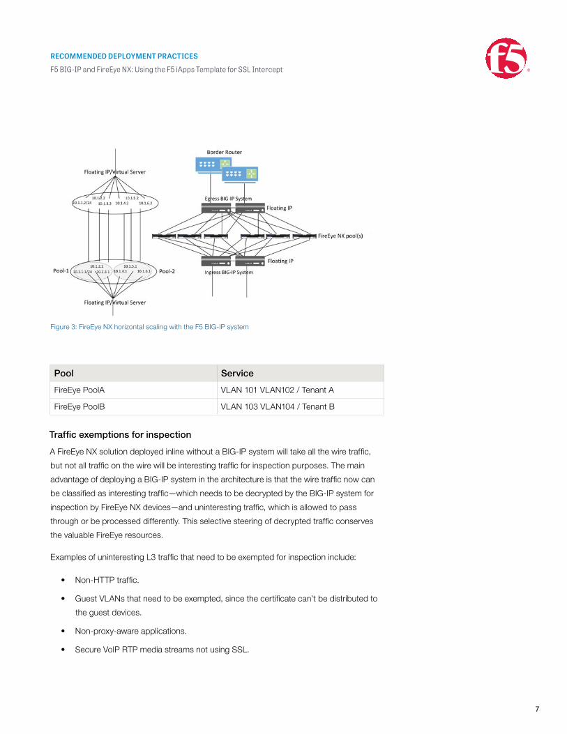
Horizontal scaling
Identify the services to which the BIG-IP system needs to send decrypted traffic. (For the
purposes of this solution deployment, a service is a pool of FireEye devices to which the
BIG-IP system load balances unencrypted traffic.
It is common to configure a single pool of FireEye NX devices, with the BIG-IP system load
balancing the unencrypted HTTP and decrypted HTTPS traffic to all the pool members.
However, you could need multiple FireEye pools, with each pool taking a different traffic
set based on user-defined criteria, such as VLAN tenant or OS type. For example, a pool
named Pool_Win might take only the Windows VLAN traffic while Pool_Mac takes only
the Macintosh OS traffic. In such cases, the BIG-IP system can be configured to steer
the traffic to the designated pool based on user-defined criteria (for instance,
using OS fingerprinting or VLANs), while load balancing the traffic to all the members
of the designated pool.
RECOMMENDED DEPLOYMENT PRACTICES
F5 BIG-IP and FireEye NX: Using the F5 iApps Template for SSL Intercept
7
Pool Service
FireEye PoolA VLAN 101 VLAN102 / Tenant A
FireEye PoolB VLAN 103 VLAN104 / Tenant B
Traffic exemptions for inspection
A FireEye NX solution deployed inline without a BIG-IP system will take all the wire traffic,
but not all traffic on the wire will be interesting traffic for inspection purposes. The main
advantage of deploying a BIG-IP system in the architecture is that the wire traffic now can
be classified as interesting traffic—which needs to be decrypted by the BIG-IP system for
inspection by FireEye NX devices—and uninteresting traffic, which is allowed to pass
through or be processed differently. This selective steering of decrypted traffic conserves
the valuable FireEye resources.
Examples of uninteresting L3 traffic that need to be exempted for inspection include:
• Non-HTTP traffic.
• Guest VLANs that need to be exempted, since the certificate can’t be distributed to
the guest devices.
• Non-proxy-aware applications.
• Secure VoIP RTP media streams not using SSL.
Figure 3: FireEye NX horizontal scaling with the F5 BIG-IP system
RECOMMENDED DEPLOYMENT PRACTICES
F5 BIG-IP and FireEye NX: Using the F5 iApps Template for SSL Intercept
8
URL filtering enables administrators to enforce corporate Internet use policies, preserving
privacy and regulatory compliance based on pre-defined categories. Some examples of
traffic exemptions based on URL category include:
• Financial.
• Health care.
• Government services.
Certificate
The BIG-IP system needs an SSL certificate (preferably a subordinate certificate authority
[CA] certificate) on the client SSL profile. This is used in SSL key management for
generating the encryption keys for encryption and decryption of the client SSL traffic.
Depending on the user agent/browser, the certificate may need to be imported to the
browser or the operating system.
IP addressing
While the FireEye NX device itself doesn’t require IP addressing, internally the BIG-IP
system will treat data traffic through each FireEye NX device as an IP-based (L3) hop,
whereby unique and private source and target IPs are needed on the BIG-IP system for
each of FireEye devices in the pool. F5 specifies a /30 subnet as the absolute smallest
subnet to handle just two hosts (source and target).
FireEye Subnet (example)
FireEyeNX1 172.168.10.0/30
FireEyeNX2 172.168.10.4/30
FireEyeNX”N” 172.168.10.(n-1)*4/30
Deployment modes
Various modes of deployment are available for integrating the BIG-IP system with FireEye
NX for advanced threat protection.
• SSL visibility solution with two BIG-IP systems
This is a sandwich architecture with two BIG-IP systems, one each on the ingress or
client-side for decryption and another on the egress or server-side for re-encryption
of SSL traffic, while FireEye NX devices are configured for inline mode.
RECOMMENDED DEPLOYMENT PRACTICES
F5 BIG-IP and FireEye NX: Using the F5 iApps Template for SSL Intercept
9
• SSL visibility solution with one BIG-IP system
This solution entails a single BIG-IP system deployed to perform both decryption and
re-encryption of SSL traffic, while FireEye NX devices are configured for inline mode.
• SSL visibility solution using one BIG-IP system with a clone pool
In this deployment option, the BIG-IP system passively copies or clones the client-
and/or the server-side traffic to a pool of FireEye NX devices configured in
promiscuous or monitoring mode.
These modes are applicable for either of these flows:
• Outbound flow, for example, corporate users browsing the web over HTTPS
• Inbound flow, for example, Internet users accessing the DMZ web servers securely
They’re also applicable at any data exchange points in the data center where the traffic
flows from one security zone to another.
This guide addresses advanced threat protection for outbound flows only.
Prerequisites
• The BIG-IP system must be running version 11.6 or later. The deployment information
here does not apply to previous versions.
• SSL forward proxy must be licensed and provisioned. Verify this in the BIG-IP
system’s web-based configuration utility > System > Resource Provisioning.
• URL filtering has been licensed, with SWGS provisioned (but it need not be licensed).
• To implement IP shunning (blacklisting) of malicious traffic or bad actors based on
sources or the destination IP address, BIG-IP AFM must be licensed and provisioned.
• SSL certificate and private key have been imported into the BIG-IP system.
See System > File Management > SSL Certificate List. For specific instructions
on importing certificates and keys, see the Help tab or BIG-IP system documentation
at support.f5.com.
• The SSL certificate has been imported into the certificate store of the client browser
or operating system.
RECOMMENDED DEPLOYMENT PRACTICES
F5 BIG-IP and FireEye NX: Using the F5 iApps Template for SSL Intercept
10
• Physical connectivity is established. When using a switch, create a separate
VLAN with only the switch access ports connected to the BIG-IP instance and the
FireEye NX. FireEye NX devices can also be directly connected to the BIG-IP system.
Some customers may want to use separate physical cabling for encrypted
and decrypted traffic.
• L3 connectivity has been configured between the client VLAN and BIG-IP
(the internal interface) and between the BIG-IP system and Internet edge
(the external interface). When using two BIG-IP systems, the internal interface is
configured on the ingress BIG-IP system, while the external interface is configured
on the egress BIG-IP system.
Initial SetupInitial setup addresses URL filtering, SSL bypass, and the F5 iApps® template.
Configure URL filtering. If you have licensed URL filtering on your BIG-IP system and also have provisioned either
SWGS—it does not have to be licensed—or BIG-IP APM Lite, you can add URL filtering to
the implementation. This allows you to select specific URL categories that should bypass
SSL decryption. Normally this is done for concerns over user privacy or for categories that
contain items (such as software update tools) that may rely on specific SSL certificates to
be presented as part of a verification process.
Before configuring URL filtering, F5 strongly recommends updating the URL database. This
must be performed from the BIG-IP system command line. First, ensure you can reach
download.websense.com on port 80 via the BIG-IP system. Next, from the BIG-IP LTM
command line, type the following commands:
Note that the URL category (URLDB) doesn’t currently support custom categories.
modify sys url-db download-schedule urldb download-now false modify sys url-db download-schedule urldb download-now true
RECOMMENDED DEPLOYMENT PRACTICES
F5 BIG-IP and FireEye NX: Using the F5 iApps Template for SSL Intercept
11
Configure data groups for SSL bypass.You can choose to exempt SSL offloading based on source or destination IP address/
subnet/hostname. This is achieved by configuring the SSL bypass in the iApps template
using data groups. To create the data groups:
1. On the Main tab of the BIG-IP system’s web-based configuration utility, expand
Local Traffic and then click iRules > Data Group List.
2. Click Create and choose a name.
3. In the Type field, choose Address to create the data group based on IP address or
subnet. Or choose String to add hostnames based on a string.
4. In the Name box, type a name.
5. For Address Type in Address Records, choose Host to enter a single IP address.
Or choose Network to enter a subnet and mask. Click Add.
6. When you are done adding IP addresses or network subnets, click Finish.
You will reference these data groups in the iApps configuration sections of this guide.
Import the iApps template.For the SSL visibility solution using two BIG-IP systems, import the iApps template on both
the ingress and egress BIG-IP.
1. Open a web browser and download the latest release of the iApps template.
2. Extract (unzip) the f5.sslintercept_egress.v1.0.0rc5 iApps template (or any newer
version available).
3. On the BIG-IP web-based configuration utility, expand iApps and click Templates.
4. Click Import (on the right side of the screen).
5. Select Overwrite Existing Templates.
6. Click Browse and then to the location where you saved the iApps template file.
7. Click Upload. The iApps template is now available for use.
RECOMMENDED DEPLOYMENT PRACTICES
F5 BIG-IP and FireEye NX: Using the F5 iApps Template for SSL Intercept
12
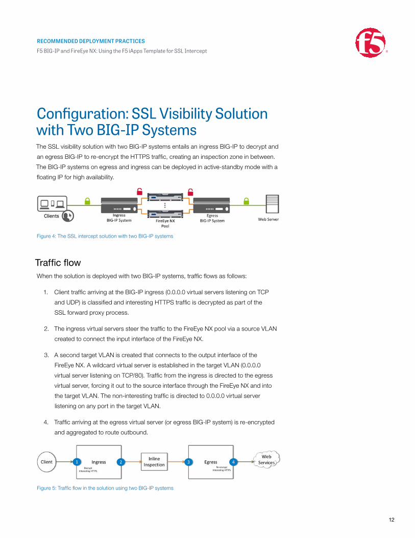
Configuration: SSL Visibility Solution with Two BIG-IP SystemsThe SSL visibility solution with two BIG-IP systems entails an ingress BIG-IP to decrypt and
an egress BIG-IP to re-encrypt the HTTPS traffic, creating an inspection zone in between.
The BIG-IP systems on egress and ingress can be deployed in active-standby mode with a
floating IP for high availability.
Traffic flowWhen the solution is deployed with two BIG-IP systems, traffic flows as follows:
1. Client traffic arriving at the BIG-IP ingress (0.0.0.0 virtual servers listening on TCP
and UDP) is classified and interesting HTTPS traffic is decrypted as part of the
SSL forward proxy process.
2. The ingress virtual servers steer the traffic to the FireEye NX pool via a source VLAN
created to connect the input interface of the FireEye NX.
3. A second target VLAN is created that connects to the output interface of the
FireEye NX. A wildcard virtual server is established in the target VLAN (0.0.0.0
virtual server listening on TCP/80). Traffic from the ingress is directed to the egress
virtual server, forcing it out to the source interface through the FireEye NX and into
the target VLAN. The non-interesting traffic is directed to 0.0.0.0 virtual server
listening on any port in the target VLAN.
4. Traffic arriving at the egress virtual server (or egress BIG-IP system) is re-encrypted
and aggregated to route outbound.
Figure 4: The SSL intercept solution with two BIG-IP systems
Figure 5: Traffic flow in the solution using two BIG-IP systems
RECOMMENDED DEPLOYMENT PRACTICES
F5 BIG-IP and FireEye NX: Using the F5 iApps Template for SSL Intercept
13
Ingress BIG-IP configurationIn the sample configuration below, /30 networks from CIDR block 172.16.10.0 are used for
the FireEye NX source and target VLAN configuration. The BIG-IP system load balances the
traffic to a single pool of two FireEye NX devices, FireEyeA and FireEyeB. The configuration
assumes that L3 connectivity on the ingress VLAN and egress VLAN is already in place.
Configure the FireEye service source VLANs.
Create a service source VLAN on the ingress BIG-IP system for every FireEye NX device
connected.
1. Navigate to Network >VLANs and click VLAN List.
2. Click Create.
3. In the General properties section, enter the Name for the VLAN and VLAN Tag.
4. In the Resource section, select the interface to add to this VLAN and move it to the
untagged box.
5. Leave the rest of the settings at their defaults and click Finished.
VLAN VLAN Number VLAN TypeFireEyeA_Source_VLAN2001
2001 untagged
FireEyeB_Source_VLAN2002
2002 untagged
Configure FireEye service source L3 connectivity.
Configure an IP address on the ingress BIG-IP interface connected to the input interface of
every FireEye NX device and assign it to the corresponding service source VLAN.
1. Expand Network and select the Self IPs tab.
2. Click Create and enter a name, IP address, and netmask, and then choose the VLAN.
3. Select Allow All in the Port Lockdown list.
4. Click Finished.
RECOMMENDED DEPLOYMENT PRACTICES
F5 BIG-IP and FireEye NX: Using the F5 iApps Template for SSL Intercept
14
Interface name VLAN IP Address
1.3 FireEyeA_Source_intFireEyeA_Source_VLAN2001
172.16.10.1/30
1.4 FireEyeB_Source_intFireEyeB_Source_VLAN2002
172.16.10.5/30
Create FireEye service target nodes.
Since FireEye NX is an L2 inspection device and doesn’t take an IP address on the data
interface, you need to create a target L3 address on the interface of the egress BIG-IP
connected to the output interface of the FireEye NX. This IP is used as a member of the
FireEye NX pool assigned to the ingress virtual server for load balancing the decrypted traffic.
1. Expand Local Traffic > Node, click Node List, and click Create.
2. Enter the name and IP address (in the same /30 subnet as those configured on the
interfaces connected to the FireEye NX ingress device).
3. Click Finished.
Node IP Address
FireEyeA 172.16.10.2/30
FireEyeB 172.16.10.6/30
Configure the iApps template.
Use the iApps template to configure the virtual servers, associated profiles, iRules,
and certificate. (All configuration can also be performed manually without using
the iApps template.)
1. Expand iApp and click Application Services.
2. Enter a name and choose the SSL intercept template.
Name Template
SSLIntercept f5.sslintercept_egress.v1.0.0rc5
RECOMMENDED DEPLOYMENT PRACTICES
F5 BIG-IP and FireEye NX: Using the F5 iApps Template for SSL Intercept
15
Configure the SSL intercept application service.
Question AnswerDo you want to see inline help? Choose Yes, show inline help
Which configuration mode do you want to use?
Choose Advanced—configure advanced options
Virtual Server ConfigurationWhere does this BIG-IP system reside in your network?
Choose This LTM will receive ingress traffic from the clients
Which type of forward proxy are you deploying at this time?
Choose Transparent proxy
Which trusted CA certificate do you want to use to issue server certificates for client-side connections?
Select the CA certificate
Which trusted CA private key do you want to use to issue server certificates for client-side connections?
Select the CA private key
Which hostnames would you like to bypass SSL interception?
Choose the data group (which you created above; see the section called
“Configure data groups for SSL bypass”)
Which source IP addresses would you like to bypass SSL interception?
Choose the data group for SSL bypass
Which destination IP addresses would you like to bypass SSL interception?
Choose the data group for SSL bypass
Which certificate bundle contains your trusted toot CAs?
Choose the right certificate bundle
What action should be taken for an expired certificate?
Choose Drop
What action should be taken for an untrusted certificate?
Choose Drop
To which device(s) should this BIG-IP LTM forward decrypted outbound client traffic?
Select the nodes (which you created previously; see the section called “Create FireEye service target nodes”). Click Add to add multiple nodes.
On which VLANs should client-side traffic be enabled or disabled?
Choose Internal (the VLAN of the ingress BIG-IP system’s internal interface connected on the client side)
URL filteringSelect the URL filter categories to bypass decryption
RECOMMENDED DEPLOYMENT PRACTICES
F5 BIG-IP and FireEye NX: Using the F5 iApps Template for SSL Intercept
16
Leave the other settings at their defaults and click Finished.
At this point, the iApps template creates the following:
• Virtual servers
SSLIntercept_ingress_vs_anyA virtual server listening for all UDP traffic on all ports
SSLIntercept_ingress_vs_any_tcpA virtual server listening for all TCP traffic on all ports
Ingress ANY wildcard (SSLIntercept_ingress_vs_any)
Type: Performance (layer 4)
Source Address: 0.0.0.0/0
Destination Address/Mask: 0.0.0.0/0
Service Port: 0
Protocol: * All Protocols
Protocol Profile (Client): fastL4
VLAN and Tunnel Traffic: Enabled on ingress VLAN
Address Translation: Disabled
Port Translation: Disabled
Pool: SSLIntercept_ingress_pool_any
Ingress TCP wildcard (SSLIntercept_ingress_vs_any_tcp)
Type: Standard
Source Address: 0.0.0.0/0
Destination Address/Mask: 0.0.0.0/0
Service Port: 0
Protocol: TCP
HTTP Profile: HTTP
SSL Profile (Client): Ingress client SSL profile
SSL Profile (Server): Ingress server SSL profile
VLAN and Tunnel Traffic: Enabled on ingress VLAN
Source Address Translation: Auto Map
Address Translation: Disabled
Port Translation: Enabled
Pool: SSLIntercept_ingress_pool_80
iRules: Ingress TCP iRule
RECOMMENDED DEPLOYMENT PRACTICES
F5 BIG-IP and FireEye NX: Using the F5 iApps Template for SSL Intercept
17
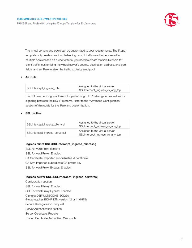
The virtual servers and pools can be customized to your requirements. The iApps
template only creates one load balancing pool. If traffic need to be steered to
multiple pools based on preset criteria, you need to create multiple listeners for
client traffic, customizing the virtual server’s source, destination address, and port
fields, and an iRule to steer the traffic to designated pool.
• An iRule
SSLIntercept_ingress_ruleAssigned to the virtual server SSLIntercept_Ingress_vs_any_tcp
The SSL intercept ingress iRule is for performing HTTPS decryption as well as for
signaling between the BIG-IP systems. Refer to the “Advanced Configuration”
section of this guide for the iRule and customization.
• SSL profiles
SSLIntercept_ingress_clientsslAssigned to the virtual server SSLIntercept_Ingress_vs_any_tcp
SSLIntercept_ingress_serversslAssigned to the virtual server SSLIntercept_Ingress_vs_any_tcp
Ingress client SSL (SSLIntercept_ingress_clientssl)
SSL Forward Proxy section:
SSL Forward Proxy: Enabled
CA Certificate: Imported subordinate CA certificate
CA Key: Imported subordinate CA private key
SSL Forward Proxy Bypass: Enabled
Ingress server SSL (SSLIntercept_ingress_serverssl)
Configuration section:
SSL Forward Proxy: Enabled
SSL Forward Proxy Bypass: Enabled
Ciphers: DEFAULT:ECDHE_ECDSA (Note: requires BIG-IP LTM version 12 or 11.6HF5)
Secure Renegotiation: Request
Server Authentication section:
Server Certificate: Require
Trusted Certificate Authorities: CA-bundle
RECOMMENDED DEPLOYMENT PRACTICES
F5 BIG-IP and FireEye NX: Using the F5 iApps Template for SSL Intercept
18
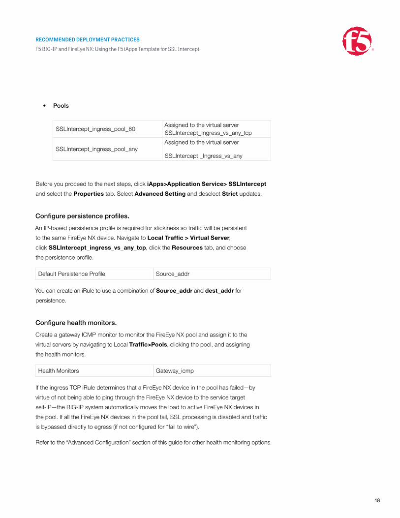
• Pools
SSLIntercept_ingress_pool_80Assigned to the virtual server SSLIntercept_Ingress_vs_any_tcp
SSLIntercept_ingress_pool_anyAssigned to the virtual server
SSLIntercept _Ingress_vs_any
Before you proceed to the next steps, click iApps>Application Service> SSLIntercept
and select the Properties tab. Select Advanced Setting and deselect Strict updates.
Configure persistence profiles.
An IP-based persistence profile is required for stickiness so traffic will be persistent
to the same FireEye NX device. Navigate to Local Traffic > Virtual Server,
click SSLIntercept_ingress_vs_any_tcp, click the Resources tab, and choose
the persistence profile.
Default Persistence Profile Source_addr
You can create an iRule to use a combination of Source_addr and dest_addr for
persistence.
Configure health monitors.
Create a gateway ICMP monitor to monitor the FireEye NX pool and assign it to the
virtual servers by navigating to Local Traffic>Pools, clicking the pool, and assigning
the health monitors.
Health Monitors Gateway_icmp
If the ingress TCP iRule determines that a FireEye NX device in the pool has failed—by
virtue of not being able to ping through the FireEye NX device to the service target
self-IP—the BIG-IP system automatically moves the load to active FireEye NX devices in
the pool. If all the FireEye NX devices in the pool fail, SSL processing is disabled and traffic
is bypassed directly to egress (if not configured for “fail to wire”).
Refer to the “Advanced Configuration” section of this guide for other health monitoring options.
RECOMMENDED DEPLOYMENT PRACTICES
F5 BIG-IP and FireEye NX: Using the F5 iApps Template for SSL Intercept
19
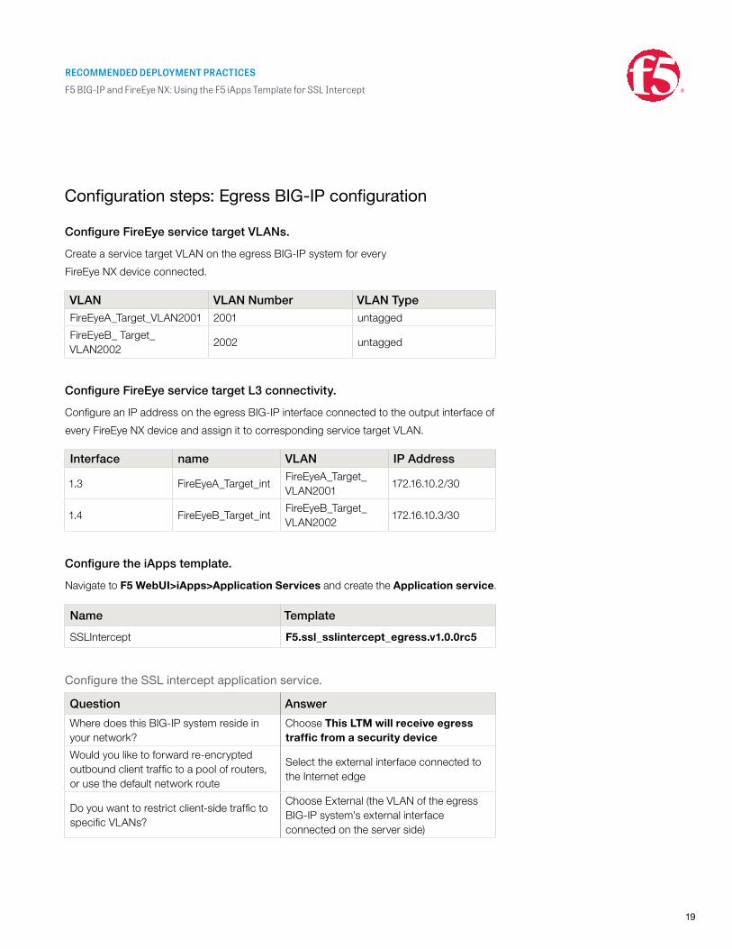
Configuration steps: Egress BIG-IP configuration
Configure FireEye service target VLANs.
Create a service target VLAN on the egress BIG-IP system for every
FireEye NX device connected.
VLAN VLAN Number VLAN TypeFireEyeA_Target_VLAN2001 2001 untagged
FireEyeB_ Target_VLAN2002
2002 untagged
Configure FireEye service target L3 connectivity.
Configure an IP address on the egress BIG-IP interface connected to the output interface of
every FireEye NX device and assign it to corresponding service target VLAN.
Interface name VLAN IP Address
1.3 FireEyeA_Target_intFireEyeA_Target_VLAN2001
172.16.10.2/30
1.4 FireEyeB_Target_intFireEyeB_Target_VLAN2002
172.16.10.3/30
Configure the iApps template.
Navigate to F5 WebUI>iApps>Application Services and create the Application service.
Name Template
SSLIntercept F5.ssl_sslintercept_egress.v1.0.0rc5
Configure the SSL intercept application service.
Question Answer
Where does this BIG-IP system reside in your network?
Choose This LTM will receive egress traffic from a security device
Would you like to forward re-encrypted outbound client traffic to a pool of routers, or use the default network route
Select the external interface connected to the Internet edge
Do you want to restrict client-side traffic to specific VLANs?
Choose External (the VLAN of the egress BIG-IP system’s external interface connected on the server side)
RECOMMENDED DEPLOYMENT PRACTICES
F5 BIG-IP and FireEye NX: Using the F5 iApps Template for SSL Intercept
20
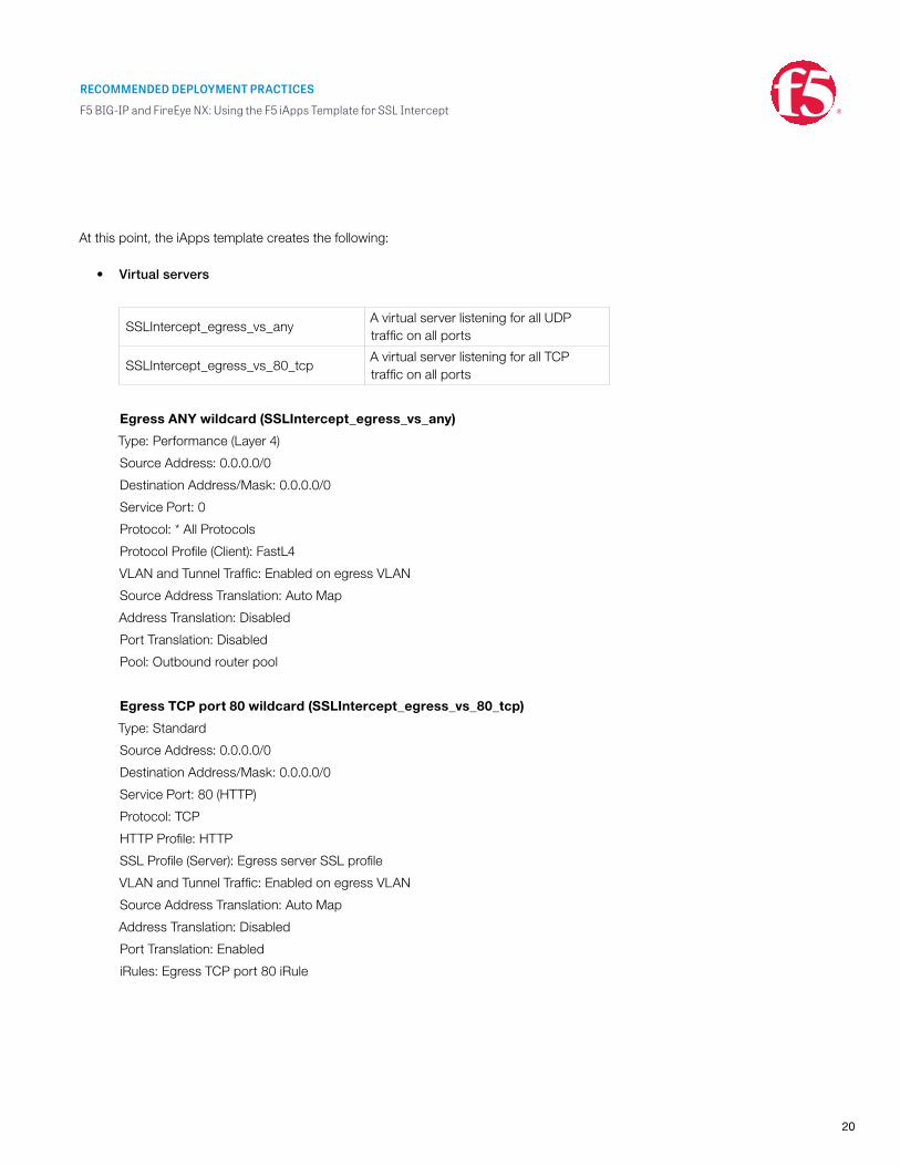
At this point, the iApps template creates the following:
• Virtual servers
SSLIntercept_egress_vs_anyA virtual server listening for all UDP traffic on all ports
SSLIntercept_egress_vs_80_tcpA virtual server listening for all TCP traffic on all ports
Egress ANY wildcard (SSLIntercept_egress_vs_any)
Type: Performance (Layer 4)
Source Address: 0.0.0.0/0
Destination Address/Mask: 0.0.0.0/0
Service Port: 0
Protocol: * All Protocols
Protocol Profile (Client): FastL4
VLAN and Tunnel Traffic: Enabled on egress VLAN
Source Address Translation: Auto Map
Address Translation: Disabled
Port Translation: Disabled
Pool: Outbound router pool
Egress TCP port 80 wildcard (SSLIntercept_egress_vs_80_tcp)
Type: Standard
Source Address: 0.0.0.0/0
Destination Address/Mask: 0.0.0.0/0
Service Port: 80 (HTTP)
Protocol: TCP
HTTP Profile: HTTP
SSL Profile (Server): Egress server SSL profile
VLAN and Tunnel Traffic: Enabled on egress VLAN
Source Address Translation: Auto Map
Address Translation: Disabled
Port Translation: Enabled
iRules: Egress TCP port 80 iRule
RECOMMENDED DEPLOYMENT PRACTICES
F5 BIG-IP and FireEye NX: Using the F5 iApps Template for SSL Intercept
21
• The SSL profile
SSLIntercept_egress_serversslAssigned to the virtual server SSLIntercept_egress_vs_80_tcp
Egress server SSL (SSLIntercept_egress_serverssl)
Configuration section:
Ciphers: DEFAULT: ECDHE_ECDSA (Note: requires BIG-IP LTM version 12 or 11.6 HF5)
Secure Renegotiation: Request
• An iRule
SSLIntercept_egress_ruleAssigned to the virtual server SSLIntercept_egress_vs_80_tcp
The SSL intercept egress rule is for performing re-encryption of the decrypted
HTTPS traffic. Refer to the “Advanced Configuration” section of this guide for the
iRule and customization.
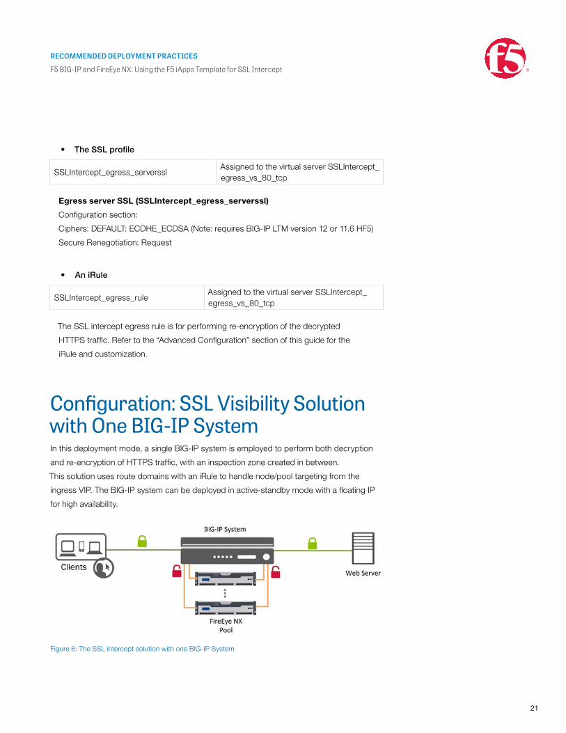
Configuration: SSL Visibility Solution with One BIG-IP SystemIn this deployment mode, a single BIG-IP system is employed to perform both decryption
and re-encryption of HTTPS traffic, with an inspection zone created in between.
This solution uses route domains with an iRule to handle node/pool targeting from the
ingress VIP. The BIG-IP system can be deployed in active-standby mode with a floating IP
for high availability.
Figure 6: The SSL intercept solution with one BIG-IP System
RECOMMENDED DEPLOYMENT PRACTICES
F5 BIG-IP and FireEye NX: Using the F5 iApps Template for SSL Intercept
22
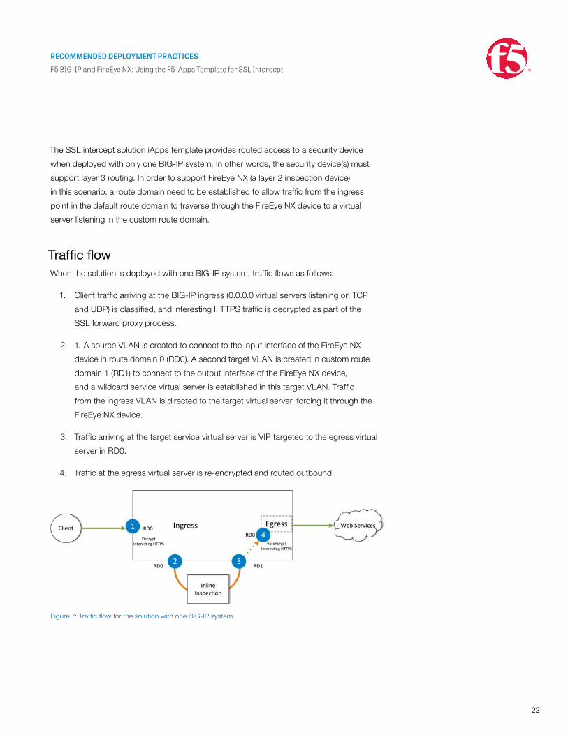
The SSL intercept solution iApps template provides routed access to a security device
when deployed with only one BIG-IP system. In other words, the security device(s) must
support layer 3 routing. In order to support FireEye NX (a layer 2 inspection device)
in this scenario, a route domain need to be established to allow traffic from the ingress
point in the default route domain to traverse through the FireEye NX device to a virtual
server listening in the custom route domain.
Traffic flowWhen the solution is deployed with one BIG-IP system, traffic flows as follows:
1. Client traffic arriving at the BIG-IP ingress (0.0.0.0 virtual servers listening on TCP
and UDP) is classified, and interesting HTTPS traffic is decrypted as part of the
SSL forward proxy process.
2. 1. A source VLAN is created to connect to the input interface of the FireEye NX
device in route domain 0 (RD0). A second target VLAN is created in custom route
domain 1 (RD1) to connect to the output interface of the FireEye NX device,
and a wildcard service virtual server is established in this target VLAN. Traffic
from the ingress VLAN is directed to the target virtual server, forcing it through the
FireEye NX device.
3. Traffic arriving at the target service virtual server is VIP targeted to the egress virtual
server in RD0.
4. Traffic at the egress virtual server is re-encrypted and routed outbound.
Figure 7: Traffic flow for the solution with one BIG-IP system
RECOMMENDED DEPLOYMENT PRACTICES
F5 BIG-IP and FireEye NX: Using the F5 iApps Template for SSL Intercept
23
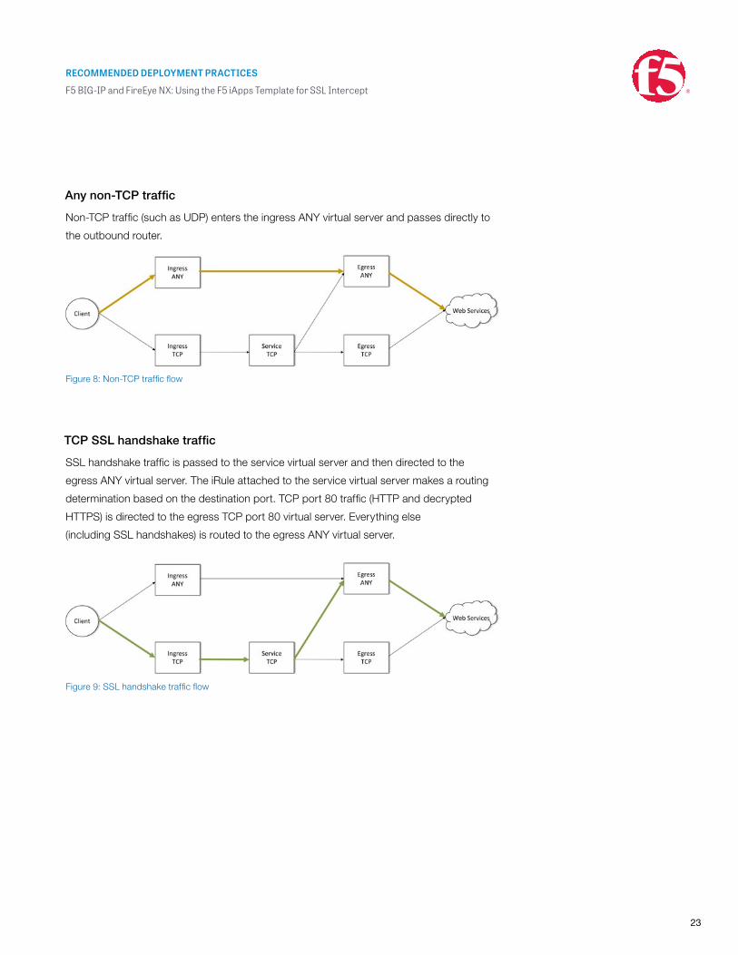
Any non-TCP traffic
Non-TCP traffic (such as UDP) enters the ingress ANY virtual server and passes directly to
the outbound router.
TCP SSL handshake traffic
SSL handshake traffic is passed to the service virtual server and then directed to the
egress ANY virtual server. The iRule attached to the service virtual server makes a routing
determination based on the destination port. TCP port 80 traffic (HTTP and decrypted
HTTPS) is directed to the egress TCP port 80 virtual server. Everything else
(including SSL handshakes) is routed to the egress ANY virtual server.
Figure 8: Non-TCP traffic flow
Figure 9: SSL handshake traffic flow
RECOMMENDED DEPLOYMENT PRACTICES
F5 BIG-IP and FireEye NX: Using the F5 iApps Template for SSL Intercept
24
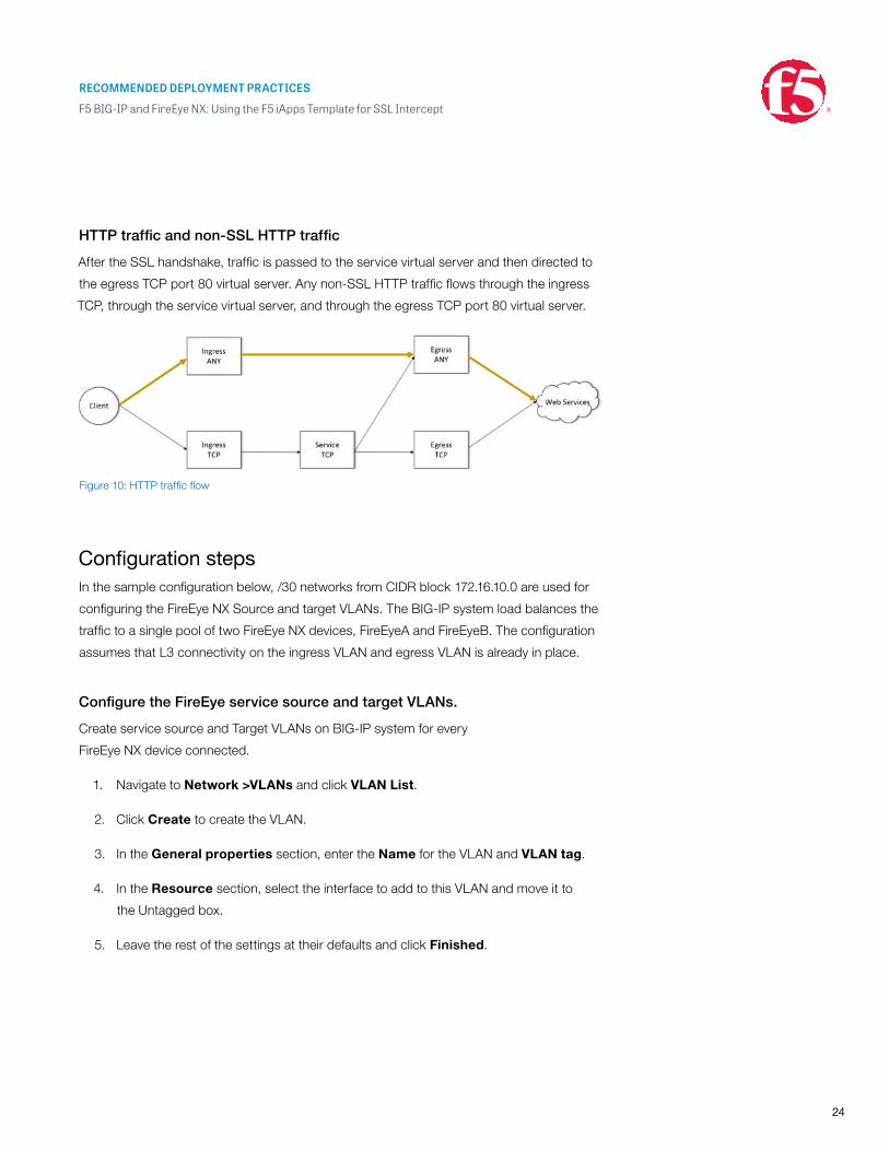
HTTP traffic and non-SSL HTTP traffic
After the SSL handshake, traffic is passed to the service virtual server and then directed to
the egress TCP port 80 virtual server. Any non-SSL HTTP traffic flows through the ingress
TCP, through the service virtual server, and through the egress TCP port 80 virtual server.
Configuration stepsIn the sample configuration below, /30 networks from CIDR block 172.16.10.0 are used for
configuring the FireEye NX Source and target VLANs. The BIG-IP system load balances the
traffic to a single pool of two FireEye NX devices, FireEyeA and FireEyeB. The configuration
assumes that L3 connectivity on the ingress VLAN and egress VLAN is already in place.
Configure the FireEye service source and target VLANs.
Create service source and Target VLANs on BIG-IP system for every
FireEye NX device connected.
1. Navigate to Network >VLANs and click VLAN List.
2. Click Create to create the VLAN.
3. In the General properties section, enter the Name for the VLAN and VLAN tag.
4. In the Resource section, select the interface to add to this VLAN and move it to
the Untagged box.
5. Leave the rest of the settings at their defaults and click Finished.
Figure 10: HTTP traffic flow
RECOMMENDED DEPLOYMENT PRACTICES
F5 BIG-IP and FireEye NX: Using the F5 iApps Template for SSL Intercept
25
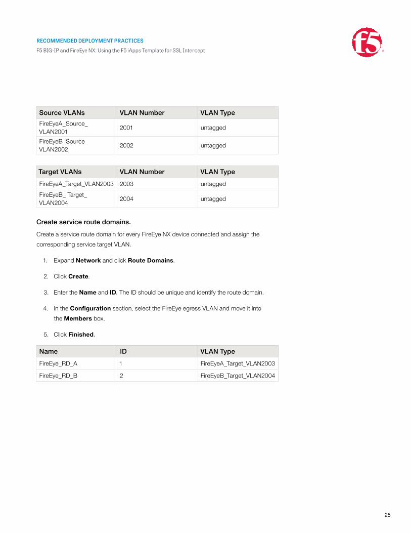
Source VLANs VLAN Number VLAN Type
FireEyeA_Source_VLAN2001
2001 untagged
FireEyeB_Source_VLAN2002
2002 untagged
Target VLANs VLAN Number VLAN Type
FireEyeA_Target_VLAN2003 2003 untagged
FireEyeB_ Target_VLAN2004
2004 untagged
Create service route domains.
Create a service route domain for every FireEye NX device connected and assign the
corresponding service target VLAN.
1. Expand Network and click Route Domains.
2. Click Create.
3. Enter the Name and ID. The ID should be unique and identify the route domain.
4. In the Configuration section, select the FireEye egress VLAN and move it into
the Members box.
5. Click Finished.
Name ID VLAN Type
FireEye_RD_A 1 FireEyeA_Target_VLAN2003
FireEye_RD_B 2 FireEyeB_Target_VLAN2004
RECOMMENDED DEPLOYMENT PRACTICES
F5 BIG-IP and FireEye NX: Using the F5 iApps Template for SSL Intercept
26
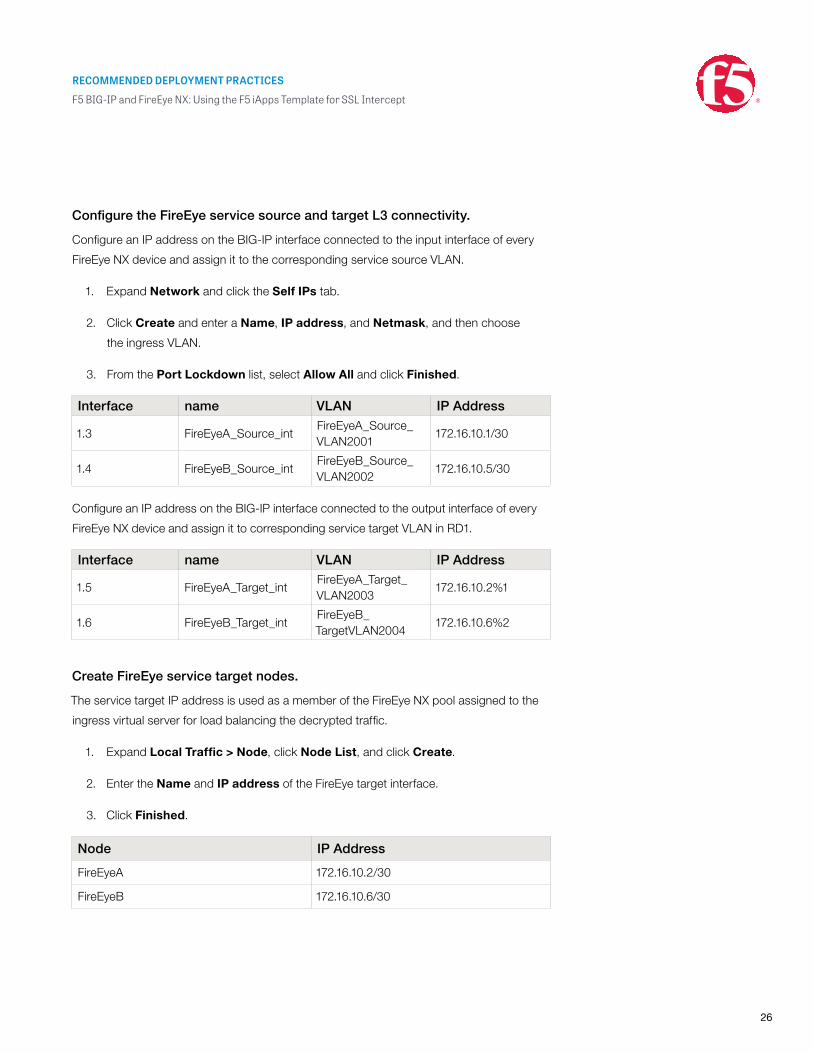
Configure the FireEye service source and target L3 connectivity.
Configure an IP address on the BIG-IP interface connected to the input interface of every
FireEye NX device and assign it to the corresponding service source VLAN.
1. Expand Network and click the Self IPs tab.
2. Click Create and enter a Name, IP address, and Netmask, and then choose
the ingress VLAN.
3. From the Port Lockdown list, select Allow All and click Finished.
Interface name VLAN IP Address
1.3 FireEyeA_Source_intFireEyeA_Source_VLAN2001
172.16.10.1/30
1.4 FireEyeB_Source_intFireEyeB_Source_VLAN2002
172.16.10.5/30
Configure an IP address on the BIG-IP interface connected to the output interface of every
FireEye NX device and assign it to corresponding service target VLAN in RD1.
Interface name VLAN IP Address
1.5 FireEyeA_Target_intFireEyeA_Target_VLAN2003
172.16.10.2%1
1.6 FireEyeB_Target_intFireEyeB_TargetVLAN2004
172.16.10.6%2
Create FireEye service target nodes.
The service target IP address is used as a member of the FireEye NX pool assigned to the
ingress virtual server for load balancing the decrypted traffic.
1. Expand Local Traffic > Node, click Node List, and click Create.
2. Enter the Name and IP address of the FireEye target interface.
3. Click Finished.
Node IP Address
FireEyeA 172.16.10.2/30
FireEyeB 172.16.10.6/30
RECOMMENDED DEPLOYMENT PRACTICES
F5 BIG-IP and FireEye NX: Using the F5 iApps Template for SSL Intercept
27
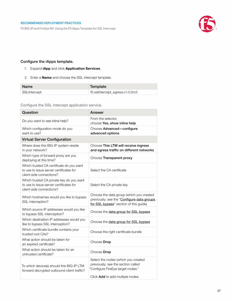
Configure the iApps template.
1. Expand iApp and click Application Services.
2. Enter a Name and choose the SSL intercept template.
Name TemplateSSLIntercept f5.sslintercept_egress.v1.0.0rc5
Configure the SSL intercept application service.
Question Answer
Do you want to see inline help?From the selector, choose Yes, show inline help
Which configuration mode do you want to use?
Choose Advanced—configure advanced options
Virtual Server Configuration
Where does this BIG-IP system reside in your network?
Choose This LTM will receive ingress and egress traffic on different networks
Which type of forward proxy are you deploying at this time?
Choose Transparent proxy
Which trusted CA certificate do you want to use to issue server certificates for client-side connections?
Select the CA certificate
Which trusted CA private key do you want to use to issue server certificates for client-side connections?
Select the CA private key
Which hostnames would you like to bypass SSL interception?
Choose the data group (which you created previously; see the “Configure data groups for SSL bypass” section of this guide)
Which source IP addresses would you like to bypass SSL interception?
Choose the data group for SSL bypass
Which destination IP addresses would you like to bypass SSL interception?
Choose the data group for SSL bypass
Which certificate bundle contains your trusted root CAs?
Choose the right certificate bundle
What action should be taken for an expired certificate?
Choose Drop
What action should be taken for an untrusted certificate?
Choose Drop
To which device(s) should this BIG-IP LTM forward decrypted outbound client traffic?
Select the nodes (which you created previously; see the section called
“Configure FireEye target nodes.”
Click Add to add multiple nodes.
RECOMMENDED DEPLOYMENT PRACTICES
F5 BIG-IP and FireEye NX: Using the F5 iApps Template for SSL Intercept
28
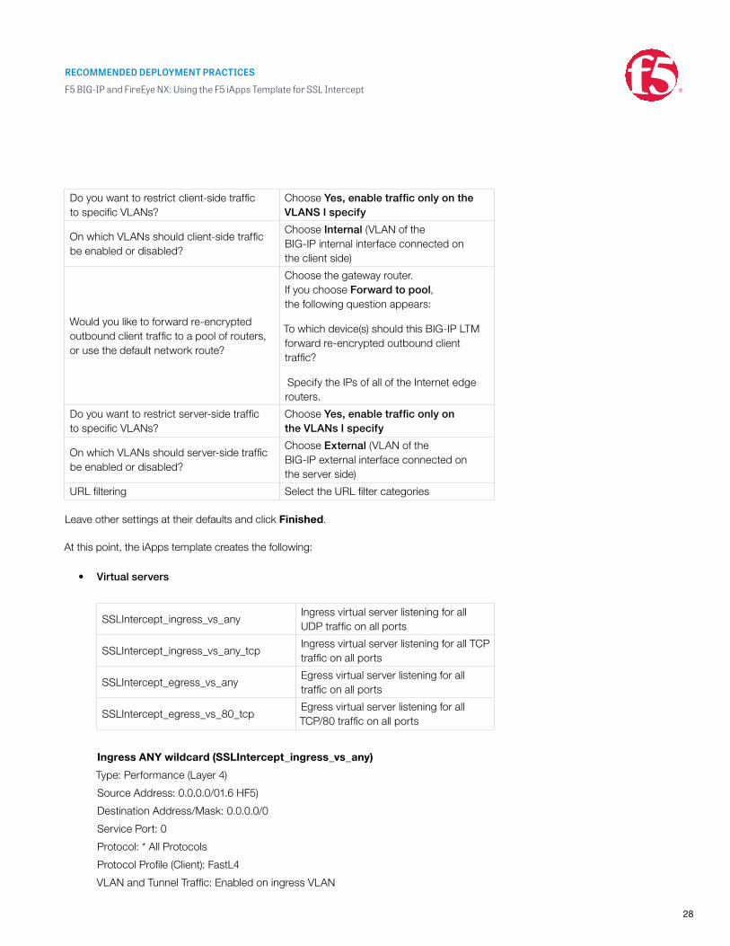
Do you want to restrict client-side traffic to specific VLANs?
Choose Yes, enable traffic only on the VLANS I specify
On which VLANs should client-side traffic be enabled or disabled?
Choose Internal (VLAN of the BIG-IP internal interface connected on the client side)
Would you like to forward re-encrypted outbound client traffic to a pool of routers, or use the default network route?
Choose the gateway router. If you choose Forward to pool, the following question appears:
To which device(s) should this BIG-IP LTM forward re-encrypted outbound client traffic?
Specify the IPs of all of the Internet edge routers.
Do you want to restrict server-side traffic to specific VLANs?
Choose Yes, enable traffic only on the VLANs I specify
On which VLANs should server-side traffic be enabled or disabled?
Choose External (VLAN of the BIG-IP external interface connected on the server side)
URL filtering Select the URL filter categories
Leave other settings at their defaults and click Finished.
At this point, the iApps template creates the following:
• Virtual servers
SSLIntercept_ingress_vs_anyIngress virtual server listening for all UDP traffic on all ports
SSLIntercept_ingress_vs_any_tcpIngress virtual server listening for all TCP traffic on all ports
SSLIntercept_egress_vs_anyEgress virtual server listening for all traffic on all ports
SSLIntercept_egress_vs_80_tcpEgress virtual server listening for all TCP/80 traffic on all ports
Ingress ANY wildcard (SSLIntercept_ingress_vs_any)
Type: Performance (Layer 4)
Source Address: 0.0.0.0/01.6 HF5)
Destination Address/Mask: 0.0.0.0/0
Service Port: 0
Protocol: * All Protocols
Protocol Profile (Client): FastL4
VLAN and Tunnel Traffic: Enabled on ingress VLAN
RECOMMENDED DEPLOYMENT PRACTICES
F5 BIG-IP and FireEye NX: Using the F5 iApps Template for SSL Intercept
29
Address Translation: Disabled
Port Translation: Disabled
Pool: Outbound router pool
Ingress TCP wildcard (SSLIntercept_ingress_vs_any_tcp)
Type: Standard
Source Address: 0.0.0.0/0
Destination Address/Mask: 0.0.0.0/0
Service Port: 0
Protocol: TCP
HTTP Profile: HTTP
SSL Profile (Client): Ingress client SSL profile
SSL Profile (Server): Ingress server SSL profile
VLAN and Tunnel Traffic: Enabled on ingress VLAN
Address Translation: Disabled
Port Translation: Enabled
iRules: Ingress TCP iRule
Egress ANY wildcard (SSLIntercept_egress_vs_any)
Type: Performance (Layer 4)
Source Address: 0.0.0.0/0
Destination Address/Mask: 0.0.0.0/0
Service Port: 0
Protocol: * All Protocols
Protocol Profile (Client): FastL4
VLAN and Tunnel Traffic: Enabled on egress VLAN
Source Address Translation: Auto Map
Address Translation: Disabled
Port Translation: Disabled
Pool: Outbound router pool
Egress TCP port 80 wildcard (SSLIntercept_egress_vs_80_tcp)
Type: Standard
Source Address: 0.0.0.0/0
Destination Address/Mask: 0.0.0.0/0
Service Port: 80 (HTTP)
Protocol: TCP
HTTP Profile: HTTP
SSL Profile (Server): Egress server SSL profile
RECOMMENDED DEPLOYMENT PRACTICES
F5 BIG-IP and FireEye NX: Using the F5 iApps Template for SSL Intercept
30
VLAN and Tunnel Traffic: Enabled on egress VLAN
Source Address Translation: Auto Map
Address Translation: Disabled
Port Translation: Enabled
iRules: Egress TCP port 80 iRule
The virtual servers and pools can be customized to your requirements. The iApps
template only creates one load balancing pool. If traffic needs to be steered to
multiple pools based on preset criteria, you need to create multiple listeners for
client traffic, customizing the virtual server’s source, destination address, and port
fields, and an iRule to steer the traffic to designated pool.
• SSL profiles
SSLIntercept_ingress_clientssl Assigned to the virtual server SSLIntercept_ingress_vs_any_tcp
SSLIntercept_ingress_serverssl Assigned to the virtual server SSLIntercept_ingress_vs_any_tcp
SSLIntercept_egress_serversslAssigned to the virtual server SSLIntercept_egress_vs_80_tcp
Ingress client SSL (SSLIntercept_ingress_clientssl)
Under the SSL Forward Proxy section:
SSL Forward Proxy: Enabled
CA Certificate: Imported subordinate CA certificate
CA Key: Imported subordinate CA private key
SSL Forward Proxy Bypass: Enabled
Ingress server SSL (SSLIntercept_serverssl)
Under the Configuration section:
SSL Forward Proxy: Enabled
SSL Forward Proxy Bypass: Enabled
Ciphers: DEFAULT: ECDHE_ECDSA (Note: requires BIG-IP LTM version 12 or 11.6HF5)
Secure Renegotiation: Request
Under the Server Authentication section:
Server Certificate: Require
Trusted Certificate Authorities: CA-bundle
RECOMMENDED DEPLOYMENT PRACTICES
F5 BIG-IP and FireEye NX: Using the F5 iApps Template for SSL Intercept
31
Egress server SSL (SSLIntercept_Egress_serverssl)
Under the Configuration section:
Ciphers: DEFAULT: ECDHE_ECDSA (Note: requires BIG-IP LTM version 12 or 11.6 HF5)
Secure Renegotiation: Request
• iRules
SSLIntercept_ingress_ruleAssigned to the virtual server SSLIntercept_ingress_vs_any_tcp
SSLIntercept_egress_ruleAssigned to the virtual server SSLIntercept_egress_vs_80_tcp
The SSL intercept ingress rule is for performing decryption and signaling between the
ingress and egress virtual servers. The SSL intercept egress rule is for performing
re-encryption of the decrypted HTTPS traffic. Refer to the “Advanced Configuration”
section of this guide for the iRule and customization procedures for bypassing
non-HTTP traffic.
• Pools
SSLIntercept_ingress_pool_80Assigned to the virtual server SSLIntercept_egress_vs_any_tcp
SSLIntercept_ingress_pool_anyAssigned to the virtual server SSLIntercept_egress_vs_any
Customize the iApps template.
Click iApps>Application Service> SSLIntercept and select the Properties tab.
Select Advanced setting and deselect Strict updates.
Bypass UDP traffic.
UDP traffic is uninteresting traffic for inspection and need not be steered through the
FireEye NX devices but instead can be bypassed directly to the gateway IP.
To create the bypass pool:
1. Expand Local Traffic and click Pools.
2. Click Create and enter a name for the pool.
3. In the Resources section, under New Members, enter the Node Name,
Address and Service port number.
4. Click Add.
5. When done, click Finished.
RECOMMENDED DEPLOYMENT PRACTICES
F5 BIG-IP and FireEye NX: Using the F5 iApps Template for SSL Intercept
32
Pool Name Node name IP address Service Port
Bypass_UDP Externet_Edge <Gateway_IP_Address> *
Assign the pool to the ingress virtual server.
1. Expand Local Traffic, click Virtual Servers and click
SSLIntercept_ingress_vs_any.
2. Click Resource. In the Load Balancing section’s Default Pool selector, choose
the Bypass_UDP pool you created above.
3. Click Update.
Create the virtual server in the service route domain.
The iApps template is not aware of the route domain and will not create a listener in the
route domain. To create the service virtual servers:
1. Expand Local Traffic, click Virtual Servers, and click Create.
2. Enter the Name and Source IP address.
3. Choose Network as the Destination Type and enter an IP address and netmask.
4. In the Configuration section, choose TCP in the protocol list.
5. When done, click Finished.
Name Source Destination Mask Service port Protocol
FireEyeA_Service_vs
0.0.0.0%1 0.0.0.0%1 0.0.0.0 * TCP
FireEyeB_Service_vs
0.0.0.0%2 0.0.0.0%2 0.0.0.0 * TCP
Service wildcard (FireEye_Service_vs)
Type: Standard
Source Address: 0.0.0.0%1/0
Destination Address/Mask: 0.0.0.0%1/0
Service Port: 0
RECOMMENDED DEPLOYMENT PRACTICES
F5 BIG-IP and FireEye NX: Using the F5 iApps Template for SSL Intercept
33
Protocol: TCP
VLAN and Tunnel Traffic: Enabled on service target VLAN
Address Translation: Disabled
Port Translation: Disabled
iRules: Service iRule
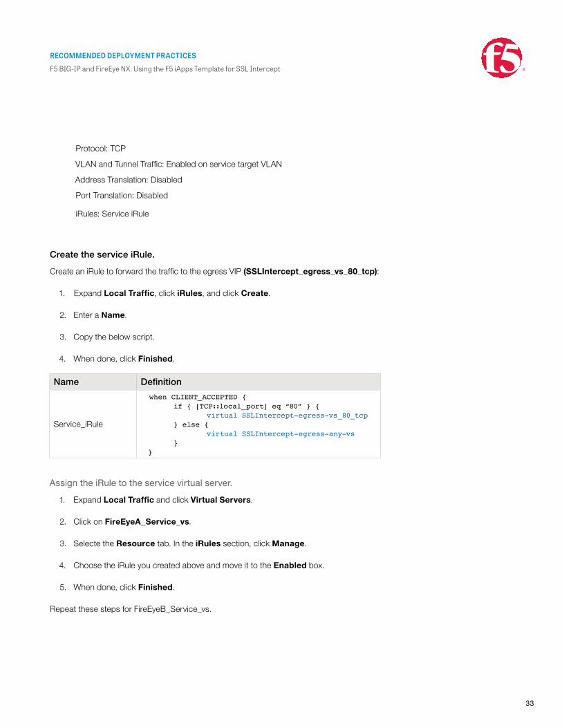
Create the service iRule.
Create an iRule to forward the traffic to the egress VIP (SSLIntercept_egress_vs_80_tcp):
1. Expand Local Traffic, click iRules, and click Create.
2. Enter a Name.
3. Copy the below script.
4. When done, click Finished.
Name Definition
Service_iRule
when CLIENT_ACCEPTED { if { [TCP::local_port] eq “80” } { virtual SSLIntercept-egress-vs_80_tcp } else { virtual SSLIntercept-egress-any-vs } }
Assign the iRule to the service virtual server.
1. Expand Local Traffic and click Virtual Servers.
2. Click on FireEyeA_Service_vs.
3. Selecte the Resource tab. In the iRules section, click Manage.
4. Choose the iRule you created above and move it to the Enabled box.
5. When done, click Finished.
Repeat these steps for FireEyeB_Service_vs.
RECOMMENDED DEPLOYMENT PRACTICES
F5 BIG-IP and FireEye NX: Using the F5 iApps Template for SSL Intercept
34
Configure persistence profiles.
You need an IP-based persistence profile for stickiness so the traffic is persistent to the
same FireEye NX device. Navigate to Local Traffic > Virtual Server and click
SSLIntercept_egress_vs_any_tcp, click the Resources tab,
and choose the persistence profile.
Default Persistence Profile Source_addr
You can create an iRule to use a combination of Source_addr and
dest_addr for persistence.
Configure health monitors.
Create a gateway ICMP monitor to monitor the FireEye NX pool and assign it to the virtual
servers by navigating to Local Traffic>Pools, clicking the pool, and assigning
the health monitors.
Health Monitors Gateway_icmp
If the ingress TCP iRule determines that a FireEye NX device in the pool has failed—by
virtue of not being able to ping through the FireEye NX device to the service target self-IP—
the BIG-IP system automatically moves the load to active FireEye NX devices. If all the
FireEye NX devices in the pool fail, SSL processing is disabled and traffic is bypassed
directly to egress (if not configured for “fail to wire”).
Refer to the “Advanced Configuration” section of this guide for other
health monitoring options.
RECOMMENDED DEPLOYMENT PRACTICES
F5 BIG-IP and FireEye NX: Using the F5 iApps Template for SSL Intercept
35
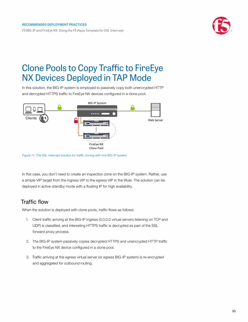
Clone Pools to Copy Traffic to FireEye NX Devices Deployed in TAP ModeIn this solution, the BIG-IP system is employed to passively copy both unencrypted HTTP
and decrypted HTTPS traffic to FireEye NX devices configured in a clone pool.
In this case, you don’t need to create an inspection zone on the BIG-IP system. Rather, use
a simple VIP target from the ingress VIP to the egress VIP in the iRule. The solution can be
deployed in active-standby mode with a floating IP for high availability.
Traffic flowWhen the solution is deployed with clone pools, traffic flows as follows:
1. Client traffic arriving at the BIG-IP ingress (0.0.0.0 virtual servers listening on TCP and
UDP) is classified, and interesting HTTPS traffic is decrypted as part of the SSL
forward proxy process.
2. The BIG-IP system passively copies decrypted HTTPS and unencrypted HTTP traffic
to the FireEye NX device configured in a clone pool.
3. Traffic arriving at the egress virtual server (or egress BIG-IP system) is re-encrypted
and aggregated for outbound routing.
Figure 11: The SSL intercept solution for traffic cloning with one BIG-IP system
RECOMMENDED DEPLOYMENT PRACTICES
F5 BIG-IP and FireEye NX: Using the F5 iApps Template for SSL Intercept
36
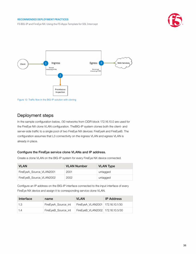
Deployment stepsIn the sample configuration below, /30 networks from CIDR block 172.16.10.0 are used for
the FireEye NX clone VLAN configuration. TheBIG-IP system clones both the client- and
server-side traffic to a single pool of two FireEye NX devices: FireEyeA and FireEyeB. The
configuration assumes that L3 connectivity on the ingress VLAN and egress VLAN is
already in place.
Configure the FireEye service clone VLANs and IP address.
Create a clone VLAN on the BIG-IP system for every FireEye NX device connected.
VLAN VLAN Number VLAN Type
FireEyeA_Source_VLAN2001 2001 untagged
FireEyeB_Source_VLAN2002 2002 untagged
Configure an IP address on the BIG-IP interface connected to the input interface of every
FireEye NX device and assign it to corresponding service clone VLAN.
Interface name VLAN IP Address
1.3 FireEyeA_Source_int FireEyeA_VLAN2001 172.16.10.1/30
1.4 FireEyeB_Source_int FireEyeB_VLAN2002 172.16.10.5/30
Figure 12: Traffic flow in the BIG-IP solution with cloning
RECOMMENDED DEPLOYMENT PRACTICES
F5 BIG-IP and FireEye NX: Using the F5 iApps Template for SSL Intercept
37
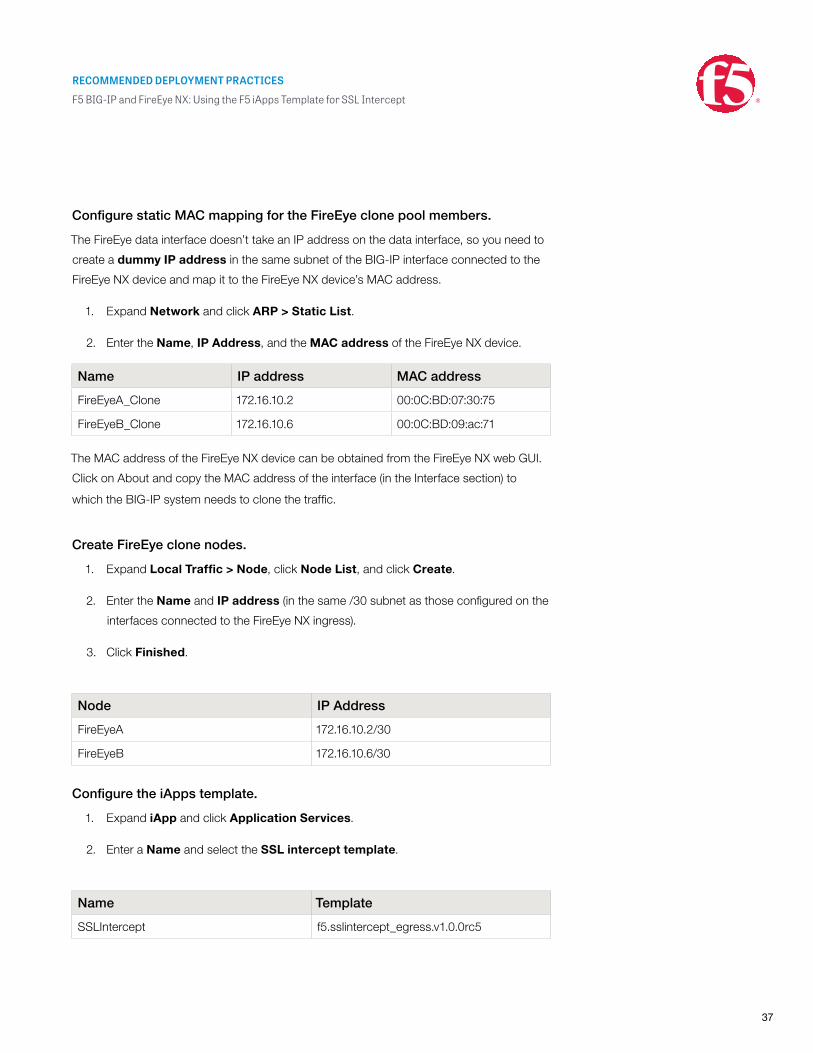
Configure static MAC mapping for the FireEye clone pool members.
The FireEye data interface doesn’t take an IP address on the data interface, so you need to
create a dummy IP address in the same subnet of the BIG-IP interface connected to the
FireEye NX device and map it to the FireEye NX device’s MAC address.
1. Expand Network and click ARP > Static List.
2. Enter the Name, IP Address, and the MAC address of the FireEye NX device.
Name IP address MAC address
FireEyeA_Clone 172.16.10.2 00:0C:BD:07:30:75
FireEyeB_Clone 172.16.10.6 00:0C:BD:09:ac:71
The MAC address of the FireEye NX device can be obtained from the FireEye NX web GUI.
Click on About and copy the MAC address of the interface (in the Interface section) to
which the BIG-IP system needs to clone the traffic.
Create FireEye clone nodes.
1. Expand Local Traffic > Node, click Node List, and click Create.
2. Enter the Name and IP address (in the same /30 subnet as those configured on the
interfaces connected to the FireEye NX ingress).
3. Click Finished.
Node IP Address
FireEyeA 172.16.10.2/30
FireEyeB 172.16.10.6/30
Configure the iApps template.
1. Expand iApp and click Application Services.
2. Enter a Name and select the SSL intercept template.
Name Template
SSLIntercept f5.sslintercept_egress.v1.0.0rc5
RECOMMENDED DEPLOYMENT PRACTICES
F5 BIG-IP and FireEye NX: Using the F5 iApps Template for SSL Intercept
38
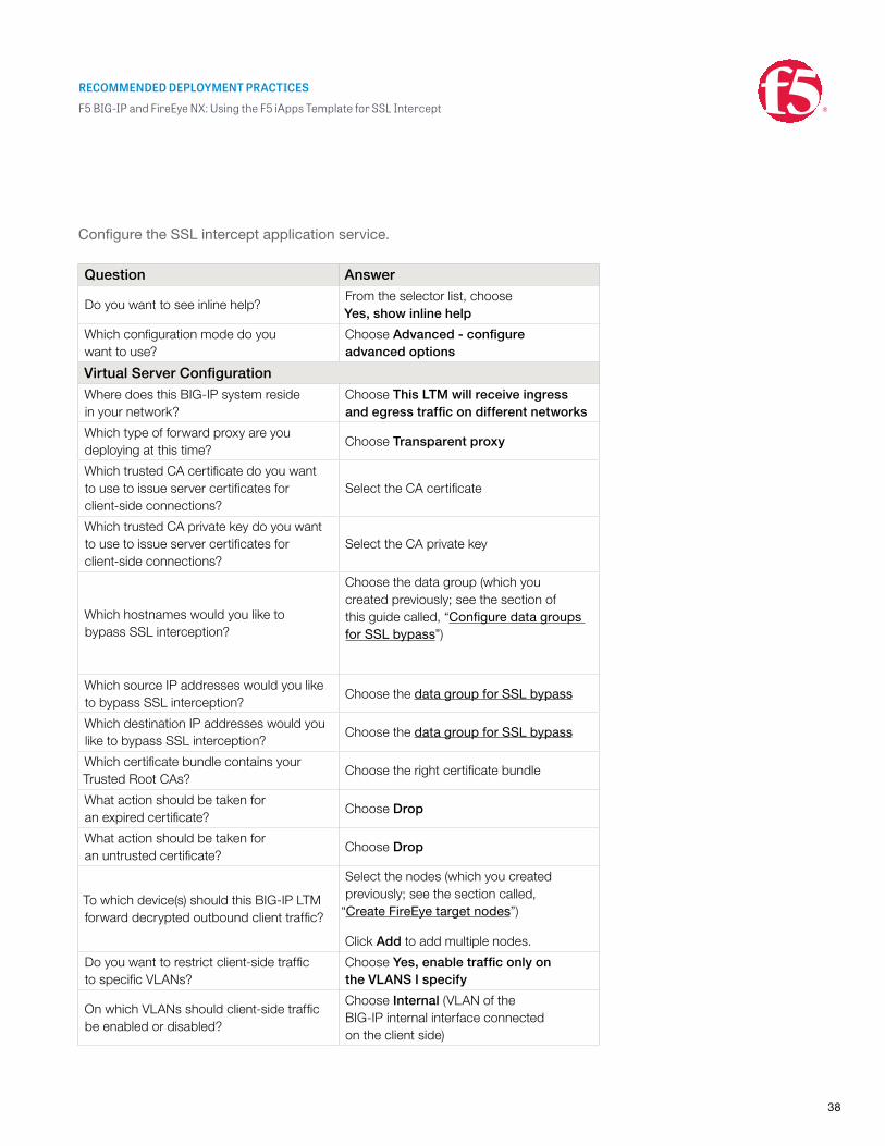
Configure the SSL intercept application service.
Question Answer
Do you want to see inline help?From the selector list, choose Yes, show inline help
Which configuration mode do you want to use?
Choose Advanced - configure advanced options
Virtual Server ConfigurationWhere does this BIG-IP system reside in your network?
Choose This LTM will receive ingress and egress traffic on different networks
Which type of forward proxy are you deploying at this time?
Choose Transparent proxy
Which trusted CA certificate do you want to use to issue server certificates for client-side connections?
Select the CA certificate
Which trusted CA private key do you want to use to issue server certificates for client-side connections?
Select the CA private key
Which hostnames would you like to bypass SSL interception?
Choose the data group (which you created previously; see the section of this guide called, “Configure data groups for SSL bypass”)
Which source IP addresses would you like to bypass SSL interception?
Choose the data group for SSL bypass
Which destination IP addresses would you like to bypass SSL interception?
Choose the data group for SSL bypass
Which certificate bundle contains your Trusted Root CAs?
Choose the right certificate bundle
What action should be taken for an expired certificate?
Choose Drop
What action should be taken for an untrusted certificate?
Choose Drop
To which device(s) should this BIG-IP LTM forward decrypted outbound client traffic?
Select the nodes (which you created previously; see the section called,
“Create FireEye target nodes”)
Click Add to add multiple nodes.
Do you want to restrict client-side traffic to specific VLANs?
Choose Yes, enable traffic only on the VLANS I specify
On which VLANs should client-side traffic be enabled or disabled?
Choose Internal (VLAN of the BIG-IP internal interface connected on the client side)
RECOMMENDED DEPLOYMENT PRACTICES
F5 BIG-IP and FireEye NX: Using the F5 iApps Template for SSL Intercept
39
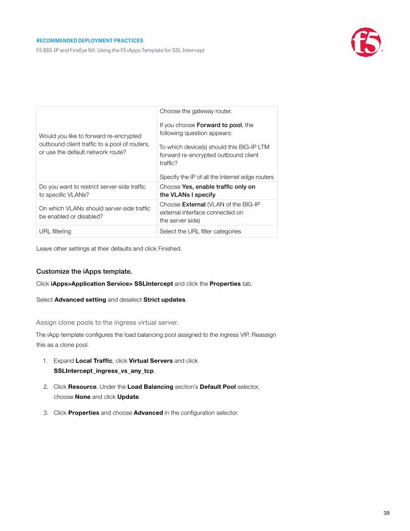
Would you like to forward re-encrypted outbound client traffic to a pool of routers, or use the default network route?
Choose the gateway router.
If you choose Forward to pool, the following question appears:
To which device(s) should this BIG-IP LTM forward re-encrypted outbound client traffic?
Specify the IP of all the Internet edge routers
Do you want to restrict server-side traffic to specific VLANs?
Choose Yes, enable traffic only on the VLANs I specify
On which VLANs should server-side traffic be enabled or disabled?
Choose External (VLAN of the BIG-IP external interface connected on the server side)
URL filtering Select the URL filter categories
Leave other settings at their defaults and click Finished.
Customize the iApps template.
Click iApps>Application Service> SSLIntercept and click the Properties tab.
Select Advanced setting and deselect Strict updates.
Assign clone pools to the ingress virtual server.
The iApp template configures the load balancing pool assigned to the ingress VIP. Reassign
this as a clone pool.
1. Expand Local Traffic, click Virtual Servers and click
SSLIntercept_ingress_vs_any_tcp.
2. Click Resource. Under the Load Balancing section’s Default Pool selector,
choose None and click Update.
3. Click Properties and choose Advanced in the configuration selector.
RECOMMENDED DEPLOYMENT PRACTICES
F5 BIG-IP and FireEye NX: Using the F5 iApps Template for SSL Intercept
40
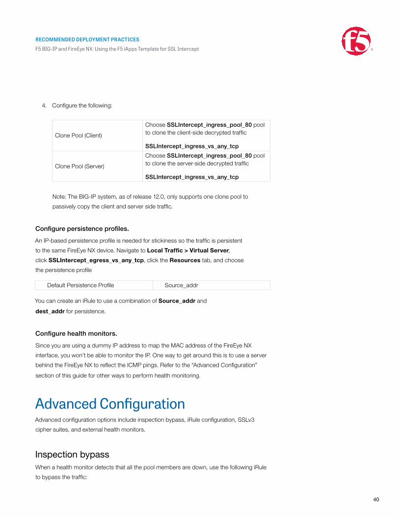
4. Configure the following:
Clone Pool (Client)
Choose SSLIntercept_ingress_pool_80 pool to clone the client-side decrypted traffic
SSLIntercept_ingress_vs_any_tcp
Clone Pool (Server)
Choose SSLIntercept_ingress_pool_80 pool to clone the server-side decrypted traffic
SSLIntercept_ingress_vs_any_tcp
Note: The BIG-IP system, as of release 12.0, only supports one clone pool to
passively copy the client and server side traffic.
Configure persistence profiles.
An IP-based persistence profile is needed for stickiness so the traffic is persistent
to the same FireEye NX device. Navigate to Local Traffic > Virtual Server,
click SSLIntercept_egress_vs_any_tcp, click the Resources tab, and choose
the persistence profile
Default Persistence Profile Source_addr
You can create an iRule to use a combination of Source_addr and
dest_addr for persistence.
Configure health monitors.
Since you are using a dummy IP address to map the MAC address of the FireEye NX
interface, you won’t be able to monitor the IP. One way to get around this is to use a server
behind the FireEye NX to reflect the ICMP pings. Refer to the “Advanced Configuration”
section of this guide for other ways to perform health monitoring.
Advanced ConfigurationAdvanced configuration options include inspection bypass, iRule configuration, SSLv3
cipher suites, and external health monitors.
Inspection bypassWhen a health monitor detects that all the pool members are down, use the following iRule
to bypass the traffic:
RECOMMENDED DEPLOYMENT PRACTICES
F5 BIG-IP and FireEye NX: Using the F5 iApps Template for SSL Intercept
41
When deploying an SSL visibility solution using two BIG-IP systems, you need to create an
out-of-band network link between the ingress BIG-IP and egress BIG-IP to bypass traffic
when the status for all the FireEye NX devices in the pool are detected as down.
You can also use the same link to bypass non-HTTP traffic.
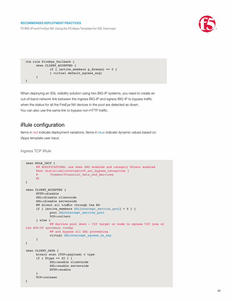
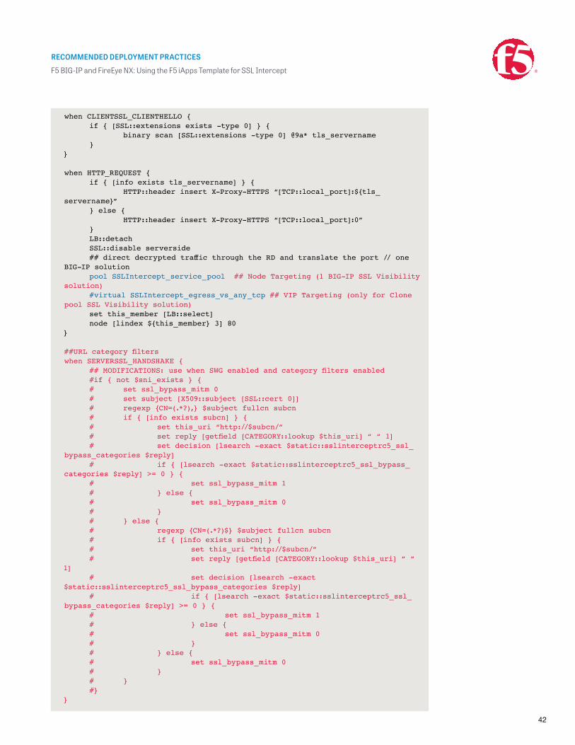
iRule configurationItems in red indicate deployment variations. Items in blue indicate dynamic values based on
iApps template user input.
Ingress TCP iRule
ltm rule FireEye_Failback { when CLIENT_ACCEPTED { if{[active_membersp_fireeye]==0} { virtual default_egress_any} }}
when RULE_INIT { ##MODIFICATIONS:usewhenSWGenabledandcategoryfiltersenabled #set static::sslinterceptrc5_ssl_bypass_categories { # /Common/Financial_Data_and_Services #}}
when CLIENT_ACCEPTED { HTTP::disable SSL::disable clientside SSL::disable serverside ##directalltrafficthroughtheRD if { [active_members SSLIntercept_service_pool] > 0 } { pool SSLIntercept_service_pool TCP::collect } else { ## Service pool down - VIP target or node to egress VIP [one or twoBIG-IPsystem(s)config] ## and bypass all SSL processing virtual SSLIntercept_egress_vs_any }}
when CLIENT_DATA { binary scan [TCP::payload] c type if{$type==22}{ SSL::enable clientside SSL::enable serverside HTTP::enable } TCP::release}
RECOMMENDED DEPLOYMENT PRACTICES
F5 BIG-IP and FireEye NX: Using the F5 iApps Template for SSL Intercept
42
when CLIENTSSL_CLIENTHELLO { if { [SSL::extensions exists -type 0] } { binary scan [SSL::extensions -type 0] @9a* tls_servername }}
when HTTP_REQUEST { if { [info exists tls_servername] } { HTTP::header insert X-Proxy-HTTPS “[TCP::local_port]:${tls_servername}” } else { HTTP::header insert X-Proxy-HTTPS “[TCP::local_port]:0” } LB::detach SSL::disable serverside ##directdecryptedtrafficthroughtheRDandtranslatetheport//oneBIG-IP solution pool SSLIntercept_service_pool ## Node Targeting (1 BIG-IP SSL Visibility solution) #virtual SSLIntercept_egress_vs_any_tcp ## VIP Targeting (only for Clone pool SSL Visibility solution) set this_member [LB::select] node [lindex ${this_member} 3] 80}
##URLcategoryfilterswhen SERVERSSL_HANDSHAKE { ##MODIFICATIONS:usewhenSWGenabledandcategoryfiltersenabled #if { not $sni_exists } { # set ssl_bypass_mitm 0 # set subject [X509::subject [SSL::cert 0]] # regexp{CN=(.*?),}$subjectfullcnsubcn # if { [info exists subcn] } { # set this_uri “http://$subcn/” # setreply[getfield[CATEGORY::lookup$this_uri]““1] # set decision [lsearch -exact $static::sslinterceptrc5_ssl_bypass_categories $reply] # if { [lsearch -exact $static::sslinterceptrc5_ssl_bypass_categories$reply]>=0}{ # set ssl_bypass_mitm 1 # } else { # set ssl_bypass_mitm 0 # } # } else { # regexp{CN=(.*?)$}$subjectfullcnsubcn # if { [info exists subcn] } { # set this_uri “http://$subcn/” # setreply[getfield[CATEGORY::lookup$this_uri]““1] # set decision [lsearch -exact $static::sslinterceptrc5_ssl_bypass_categories $reply] # if { [lsearch -exact $static::sslinterceptrc5_ssl_bypass_categories$reply]>=0}{ # set ssl_bypass_mitm 1 # } else { # set ssl_bypass_mitm 0 # } # } else { # set ssl_bypass_mitm 0 # } # } #}}
RECOMMENDED DEPLOYMENT PRACTICES
F5 BIG-IP and FireEye NX: Using the F5 iApps Template for SSL Intercept
43
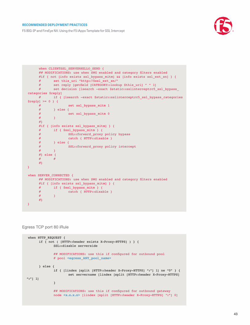
Egress TCP port 80 iRule
when HTTP_REQUEST { if { not ( [HTTP::header exists X-Proxy-HTTPS] ) } { SSL::disable serverside ##MODIFICATIONS:usethisifconfiguredforoutboundpool # pool <egress_ANY_pool_name> } else { if { [lindex [split [HTTP::header X-Proxy-HTTPS] “:”] 1] ne “0” } { set servername [lindex [split [HTTP::header X-Proxy-HTTPS] “:”] 1] } ##MODIFICATIONS:usethisifconfiguredforoutboundgateway node <x.x.x.x> [lindex [split [HTTP::header X-Proxy-HTTPS] “:”] 0]
when CLIENTSSL_SERVERHELLO_SEND { ##MODIFICATIONS:usewhenSWGenabledandcategoryfiltersenabled #if { not [info exists ssl_bypass_mitm] && [info exists ssl_ext_sn] } { # set this_uri “http://$ssl_ext_sn/” # setreply[getfield[CATEGORY::lookup$this_uri]““1] # set decision [lsearch -exact $static::sslinterceptrc5_ssl_bypass_categories $reply] # if { [lsearch -exact $static::sslinterceptrc5_ssl_bypass_categories $reply]>=0}{ # set ssl_bypass_mitm 1 # } else { # set ssl_bypass_mitm 0 # } #} #if { [info exists ssl_bypass_mitm] } { # if { $ssl_bypass_mitm } { # SSL::forward_proxy policy bypass # catch { HTTP::disable } # } else { # SSL::forward_proxy policy intercept # } #} else { # # #}}
when SERVER_CONNECTED { ##MODIFICATIONS:usewhenSWGenabledandcategoryfiltersenabled #if { [info exists ssl_bypass_mitm] } { # if { $ssl_bypass_mitm } { # catch { HTTP::disable } # } #}}
RECOMMENDED DEPLOYMENT PRACTICES
F5 BIG-IP and FireEye NX: Using the F5 iApps Template for SSL Intercept
44
SSLv3 cipher suitesSSL version 3 is considered an unsecure protocol version, so before you configure SSL
offload, check whether the ciphers you want to specify in an SSL profile include or exclude
support for SSLv3.
The DEFAULT cipher string in the BIG-IP system already excludes support for SSLv3.
That’s the good news. The bad news is that when you append certain ciphers to the
DEFAULT string (always recommended), those ciphers might pull in support for SSLv3
without your knowledge.
1. First, identify the supported cipher in SSLv3 from the bash shell. At the prompt, type
the command to see whether the cipher string you plan to type in the client
SSL profile includes support for SSLv3.
2. If you want to see which ciphers are included in the DEFAULT string, type either
of the following:
After you do this, use the information you’ve learned to type cipher strings in the client
and server SSL profiles.
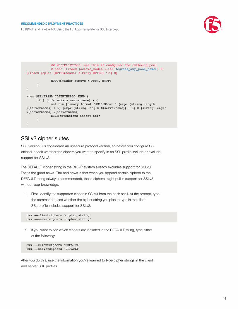
##MODIFICATIONS:usethisifconfiguredforoutboundpool # node [lindex [active_nodes -list <egress_any_pool_name>] 0] [lindex [split [HTTP::header X-Proxy-HTTPS] “:”] 0] HTTP::header remove X-Proxy-HTTPS }}
when SERVERSSL_CLIENTHELLO_SEND { if { [info exists servername] } { set bin [binary format S1S1S1S1ca* 0 [expr [string length ${servername}] + 5] [expr [string length ${servername}] + 3] 0 [string length ${servername}] ${servername}] SSL::extensions insert $bin }}
tmm --clientciphers ‘cipher_string’ tmm --serverciphers ‘cipher_string’
tmm --clientciphers ‘DEFAULT’ tmm --serverciphers ‘DEFAULT’
RECOMMENDED DEPLOYMENT PRACTICES
F5 BIG-IP and FireEye NX: Using the F5 iApps Template for SSL Intercept
45
External Health MonitorsWhen FireEye NX is deployed in non-blocking mode, ICMP health monitors in the BIG-IP
system will be unsuccessful in detecting FireEye NX device failures due to the ability to fail
to wire. The ICMP echo requests from the ingress BIG-IP system and the ICMP responses
from the egress BIG-IP system continue to pass through the failed FireEye NX device, along
with HTTP traffic without inspection.
In such cases, F5 recommends using external monitors polling the FireEye NX device out of
the band management interface. Below are some of the options to consider:
• Monitor the management IP address of the FireEye NX using ICMP gateway health
monitor on the BIG-IP system.
• Monitor the interface DOWN status on the FireEye NX web GUI using an external
script. The interface’s status can be found under the interface section at the FireEye
NX Web GUI> About.
• Poll the following FireEye SNMP MIBS for interface and system DOWN statuses.
This can be done through SNMP monitors on the BIG-IP system or using
an external script.
System status
Interface status
FE-FIREEYE-MIB::feSystemStatus.0=STRING:“Good”
IF-MIB::ifDescr:iso.1.3.6.1.2.1.2.2.1.2.
IF-MIB::ifDescr.1=STRING:loIF-MIB::ifDescr.6=STRING:ether1IF-MIB::ifDescr.7=STRING:pether2IF-MIB::ifDescr.8=STRING:pether3IF-MIB::ifDescr.9=STRING:pether4IF-MIB::ifDescr.10=STRING:ether2
IF-MIB::ifAdminStatus:iso.1.3.6.1.2.1.2.2.1.7.
IF-MIB::ifAdminStatus.1=INTEGER:up(1)|down(2)IF-MIB::ifAdminStatus.6=INTEGER:up(1)|down(2)IF-MIB::ifAdminStatus.7=INTEGER:up(1)|down(2)IF-MIB::ifAdminStatus.8=INTEGER:up(1)|down(2)IF-MIB::ifAdminStatus.9=INTEGER:up(1)|down(2)IF-MIB::ifAdminStatus.10=INTEGER:up(1)|down(2)
RECOMMENDED DEPLOYMENT PRACTICES
F5 BIG-IP and FireEye NX: Using the F5 iApps Template for SSL Intercept
©2016 F5 Networks, Inc. All rights reserved. F5, F5 Networks, and the F5 logo are trademarks of F5 Networks, Inc. in the U.S. and in certain other countries. Other F5 trademarks are identified at f5.com. Any other products, services, or company names referenced herein may be trademarks of their respective owners with no endorsement or affiliation, express or implied, claimed by F5. 0416 RECP-SSL-FIREEYE-78769856
F5 Networks, Inc. 401 Elliott Avenue West, Seattle, WA 98119 888-882-4447 f5.com
Europe/Middle-East/[email protected]
Japan [email protected]
Testing the SolutionFollowing are some ways to test the integrated solution:
1. The client on the internal network should be able to successfully access external
HTTPS web sites.
2. Packet capture on the BIG-IP system should show decrypted and re-encrypted
traffic. Refer to this F5 support document for further information on how to
perform packet capture.
3. Test from the FireEye NX web interface: Log in to the FireEye NX GUI and click About,
then click Deployment check and perform the checks there. Note that some of
these checks may cause a security alert, so it is important to engage the security
team for this testing in the production network.
IF-MIB::ifOperStatus.1=INTEGER:up(1)|down(2)IF-MIB::ifOperStatus.6=INTEGER:up(1)|down(2)IF-MIB::ifOperStatus.7=INTEGER:up(1)|down(2)IF-MIB::ifOperStatus.8=INTEGER:up(1)|down(2)IF-MIB::ifOperStatus.9=INTEGER:up(1)|down(2)IF-MIB::ifOperStatus.10=INTEGER:up(1)|down(2)
![BIG-IP® TMOS®: IP Routing Administration - F5 … · Overview of IP routing administration in TMOS ... ,FastApplicationProxy,FastCache,FirePass,GlobalTrafficManager,GTM, ... F5[DESIGN]](https://img.pdfslide.net/doc/110x75/5b909d3f09d3f2c1498c87fc/big-ip-tmos-ip-routing-administration-f5-overview-of-ip-routing-administration.jpg)


![BIG-IP® Global Traffic Manager™: Monitors Reference · F5[DESIGN] ,F5Certified[DESIGN ... TrafficManager,GTM,GUARDIAN,iApps,IBR,IntelligentBrowserReferencing,IntelligentCompression,](https://img.pdfslide.net/doc/110x75/5b5c49d57f8b9a68368c6fa1/big-ip-global-traffic-manager-monitors-reference-f5design-f5certifieddesign.jpg)


![IP Sub Sup Netting F5[1]Tarun](https://img.pdfslide.net/doc/110x75/5452ea1baf79590c308b5246/ip-sub-sup-netting-f51tarun.jpg)

