Embed Size (px)
Citation preview
Agility 2017 Hands-on Lab Guide
F5 Solutions for SSL Visibility
F5 Networks, Inc.

2

Contents:
1 Class 1: SSL Orchestrator 2.0 51.1 SSL Orchestrator Lab Environment . . . . . . . . . . . . . . . . . . . . . . . . . . . . . . . . 61.2 Module 1: Intro to SSL Orchestrator 2.0 . . . . . . . . . . . . . . . . . . . . . . . . . . . . . . 7
1.2.1 Lab 1: Create a 1-box transparent Proxy SSLO . . . . . . . . . . . . . . . . . . . . . 71.2.2 Lab 2: Create a 1-box Explicit Proxy SSLO . . . . . . . . . . . . . . . . . . . . . . . 141.2.3 Lab 3: Create custom Service Chains . . . . . . . . . . . . . . . . . . . . . . . . . . 151.2.4 Lab 4: Troubleshooting an SSLO Configuration . . . . . . . . . . . . . . . . . . . . . 17
1.3 Appendix - Common Testing Commands . . . . . . . . . . . . . . . . . . . . . . . . . . . . . 19
3

4
1Class 1: SSL Orchestrator 2.0
F5 SSL Orchestrator (SSLO) provides an all-in-one appliance solution designed specifically to optimize theSSL infrastructure, provide security devices with visibility of SSL/TLS encrypted traffic, and maximize effi-cient use of that existing security investment. This solution supports policy-based management and steeringof traffic flows to existing security devices, designed to easily integrate into existing architectures, and cen-tralizes the SSL decrypt/encrypt function by delivering the latest SSL encryption technologies across theentire security infrastructure.
Multi-Layered Security
In order to solve specific security challenges, security administrators are accustomed to manually chainingtogether multiple point products, creating a bare-bones “security stack” consisting of multiple services. Atypical stack may include components like Data Leak Prevention (DLP) scanners, Web Application Firewalls(WAF), Intrusion Prevention and Detection Systems (IPS and IDS), Malware Analysis tools, and more. Inthis model, all user sessions are provided the same level of security, as this “daisy chain” of services ishard-wired.
Dynamic Service Chaining
Dynamic Service Chaining processes specific connections based on context provided by the ClassificationEngine. These service chains can include four types of services (Layer 2 in-line services, Layer 3 in-line services, receive-only services, and ICAP services) you define, as well as any decrypt zone betweenseparate ingress and egress devices).
Classification Engine
Classification Engine provides a rich set of methods based on context to dynamically determine how bestto optimize the flow through the security stack. Context can come from the following:
• Source IP/subnet
• Destination IP/subnet
• IP intelligence category - Subscription
• IP geolocation
• Host and domain name
• URL filtering category - Subscription
• Destination port
• Protocol
5
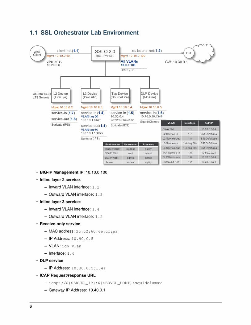
1.1 SSL Orchestrator Lab Environment
• BIG-IP Management IP: 10.10.0.100
• Inline layer 2 service:
– Inward VLAN interface: 1.2
– Outward VLAN interface: 1.3
• Inline layer 3 service:
– Inward VLAN interface: 1.4
– Outward VLAN interface: 1.5
• Receive-only service
– MAC address: 2c:c2:60:6e:cf:a2
– IP Address: 10.90.0.5
– VLAN: ids-vlan
– Interface: 1.6
• DLP service
– IP Address: 10.30.0.5:1344
• ICAP Request/response URL
– icap://${SERVER_IP}:${SERVER_PORT}/squidclamav
– Gateway IP Address: 10.40.0.1
6
1.2 Module 1: Intro to SSL Orchestrator 2.0
1.2.1 Lab 1: Create a 1-box transparent Proxy SSLO
The majority of enterprise configurations will involve a single F5 platform performing the SSL visibility task.The SSL Orchestrator has been designed with that principle in mind and performs robust security servicechaining of security devices attached to a single appliance. Extending SSLO to a two-box configurationsimply creates an additional decrypted “clear text” inspection zone between the two devices where a limitedset of non-service-chained security devices can be inserted. SSL Orchestrator 2.0 now makes configurationof a single-box deployment quite simple and intuitive. Please follow the steps below to create a 1-boxtransparent proxy SSL Orchestrator configuration.
Step 1: Review the lab diagram and map out the services and endpoints
Review the lab diagram at the beginning of this document, and make note of the security devices andinterfaces assigned to those security devices. The SSL Orchestrator iApp assumes that this information isknown so in your environment it’s important to first scope out and define all of the pieces before startingassembly.
1. The client is attached to a 10.20.0.0/24 network and is assigned the IP 10.20.0.60. This networkis attached to the BIG-IP 1.1 interface.
2. The L2 device is an Ubuntu 14.04 LTS server configured to bridge its eth1 and eth2 interfaces. Itsinbound VLAN (traffic to it) is attached to the BIG-IP 1.7 interface. Its outbound interface (trafficcoming from it) is attached to the BIG-IP 1.8 interface. The box is running open source Suricata as apassive IPS.
3. The L3 device is an Ubuntu 14.04 LTS server configured to route from its eth1 to its eth2 interface.Its inbound VLAN (traffic to it) is attached to the BIG-IP 1.4 (VLAN tag 50) interface and has anIP of 198.19.1.64/25. Its outbound interface (traffic coming from it) is attached to the BIG-IP 1.4(VLAN tag 60) interface and has an IP of 198.19.1.130/25. Its default gateway is 198.19.1.245, which will be a VLAN self-IP on the BIG-IP. The box is running open source Suricata as a passiveIPS.
4. The TAP device is an Ubuntu 14.04 LTS server configured with a single eth1 interface. That interfaceis attached to the BIG-IP 1.5 interface. The box is running open source Suricata as a passive IDS.
5. The DLP/ICAP device is an Ubuntu 14.04 LTS server configured with a single eth1 interface. Thatinterface is attached to the BIG-IP 1.6 interface and has an IP of 10.70.0.10. The box is runningc-icap and Squid/Clamav.
6. The outbound network is attached to the BIG-IP 1.2 interface, in the 10.30.0.0/24 subnet, andhas a gateway of 10.30.0.1.
7. In the lab, client inbound, Internet outbound, and isolated TAP and DLP VLANs and self-IPs arealready created. The (ADC) SSL Orchestrator iApp does not create these.
7
Step 2: Fulfill the SSL Orchestrator pre-requisites
There are a number of objects that the (ADC) SSL Orchestrator iApp does not create, and expects to existbefore deploying the iApp. You must create the following objects before starting the iApp:
1. Import the CA certificate and private key – in order to terminate and re-encrypt outbound SSLtraffic, SSL Forward Proxy must re-issue, or rather “forge” a new server certificate to the client. In orderto perform this re-issuance process, the BIG-IP must possess a certificate authority (CA) certificateand associated private key.
Note: This lab environment already has a subordinate CA certificate and private key installed.
2. Create the client inbound VLAN and self-IP – create the VLAN and self-IP that connects the clientto the BIG-IP. In this lab that’s the 10.20.0.0/24 subnet and interface 1.1 on the BIG-IP. This labenvironment already has this VLAN and self-IP created.
3. Create the Internet outbound VLAN and self-IP – create the VLAN and self-IP that connects theBIG-IP to the outbound Internet router. In this lab that’s the 10.30.0.0/24 subnet and interface 1.2on the BIG-IP. This lab environment already has this VLAN and self-IP created.
4. Create the DLP VLAN and self-IP – if it is desired to isolate the DLP/ICAP device, create the VLANand self-IP that connects the DLP device to the BIG-IP. In this lab that’s the 10.70.0.0/24 subnetand interface 1.6 on the BIG-IP. The DLP security device is listening on 10.70.0.10 and ICAP islistening on port 1344. This lab environment already has this VLAN and self-IP created.
5. Create the Receive Only VLAN and self-IP – if it is desired to isolate the TAP device, create theVLAN and self-IP that connects the TAP device to the BIG-IP, In this lab that’s the 10.50.0.0/24subnet and interface 1.5 on the BIG-IP. The TAP device doesn’t specifically have an IP address onthis subnet, but BIG-IP constructs access to passive devices with clone pools, which equates to anarbitrary IP address in a pool and static ARP entry from that IP address to the MAC address of thepassive device. In other words, BIG-IP needs a VLAN in this arbitrary subnet, 10.50.0.0/24, apool that points to an arbitrary unused IP address, 10.50.0.5, and a static ARP that points this IPaddress at the MAC address of the passive device. This lab environment already has this VLAN andself-IP created.
6. Create the default internet route for outbound traffic – the iApp provides an option to leverage adefined gateway pool, or use the system default route. If a gateway pool is not used, they systemroute table will need to have a default route used to reach Internet destination. We’ll use a gatewaypool defined within SSLO.
7. Create a log publisher – this step is optional if you desire to push debug messages to an externalSyslog server. There is no Syslog server in this lab environment, so you can skip this step.
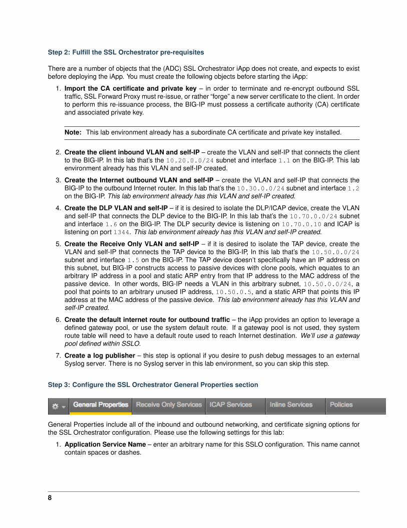
Step 3: Configure the SSL Orchestrator General Properties section
General Properties include all of the inbound and outbound networking, and certificate signing options forthe SSL Orchestrator configuration. Please use the following settings for this lab:
1. Application Service Name – enter an arbitrary name for this SSLO configuration. This name cannotcontain spaces or dashes.
8
2. Do you want to setup separate ingress and egress devices with a cleartext zone between them?– this question indicates if this is a single or two-box SSLO solution. Select No, use one BIG-IPdevice for ingress and egress to enable a single-box deployment.
3. Which IP address families do you want to implement? – SSLO can support IPv4 and IPv6 envi-ronments. In this environment, however, we’ll only be using IPv4. Select Support IPv4 only.
4. Which proxy schemes do you want to implement? – SSLO supports transparent and explicit proxyschemes. In this first lab we’ll be setting up a transparent proxy, so select Implement transparentproxy only. A transparent proxy is fundamentally a proxy service that the client is not generallyaware of; and there are a number of facilities by which to get client traffic to a transparent proxy. Theeasiest option, and the one used in this lab, is to make the proxy (SSLO ingress) the default outboundroute for the client. Other options include policy-based routing (PBR) and Web Cache CommunicationProtocol (WCCP), two techniques often employed by gateway devices to more intelligently steer trafficthrough potentially multiple outbound paths.
5. Do you want to pass UDP traffic through the transparent proxy unexamined? – if enabled, SSLOcan also process UDP traffic separate, specifically to be able to block specific UDP traffic, or detectand block Google QUIC traffic. For this lab, select Yes, Pass all UDP traffic unexamined.You may also optionally select No, manage UDP traffic by classification, whereby you’llbe presented with a separate UDP traffic classifier section on the Policies tab.
6. Do you want to pass non-TCP, non-UDP traffic through the transparent proxy unexamined? –SSLO will by default create a second non-TCP VIP to catch all non-TCP traffic, allowing the optionto either allow that traffic or block it. If the above UDP traffic option is enabled, there would be threeingress VIPs, one for TCP, one for UDP, and one for everything else. In this lab, select Yes, passNon TCP, Non UDP traffic.
7. Which is the SSL Forward Proxy CA certificate? – assuming that a CA certificate has already beeninstalled, select this certificate from the list. In this lab that will be the subca1.f5demolabs.com.crt certificate.
8. Which is the SSL Forward Proxy CA private key? – assuming that a CA private key has alreadybeen installed, select this private key from the list. In this lab that will be subca1.f5demolabs.com.key.
9. What is the private-key passphrase (if any)? – if the CA private key requires a passphrase tounlock signing functions, enter that passphrase here. In this lab the subordinate CA private key doesnot require a passphrase.
10. Which CA bundle is used to validate remote server certificates? – this option is at the heartof SSL Forward Proxy, next to the selection of the CA certificate and private key. As a functionof SSL Forward Proxy, SSLO must not only re-issue server certificates, but also validate the realserver certificates. That validation involves both expiration and public key infrastructure (PKI) trustestablishment. That trust establishment is made possible by the inclusion of a CA certificate truststore that allows the BIG-IP to build a complete trust chain form the real server certificate to anexplicitly trusted set of locally-installed CA roots. Those CA certificates are stored in a bundle fileand that bundle is represented in this configuration option. Without this CA bundle file SSLO cannotperform the PKI trust validation. The default ca-bundle.crt file is a bundle that is maintained andsourced from the Mozilla foundation, but larger more complete bundles are also available on the F5Downloads site.
11. Should connections to servers with expired certificates be allowed? – if the real server certificateis expired, SSLO provides the option to either drop the connection, or to ignore the expired certificateand allow the connection to proceed. As of BIG-IP version 12.0 and up, and expired certificate willgenerate an expired re-issued certificate to the client.
12. Should connections to servers with untrusted certificates be allowed? – if the real server certifi-cate cannot be trusted, by way of the previously-detailed PKI trust process, SSLO provides the option
9
to either drop the connection, or to ignore the untrusted certificate and allow the connection to pro-ceed. Unlike an expired certificate, as of BIG-IP version 13.0, an untrusted certificate is still re-issuedas a locally trusted certificate to the client.
13. Should strict updates be enforced for this application? – this is a standard iApp option that allowsfor, or denies write access to iApp-created objects (outside of the iApp).
14. Which VLAN(s) will bring client traffic to the transparent proxy? – this is the VLAN that clienttraffic will arrive at the BIG-IP. SSLO can process traffic from multiple incoming sources. In this labthat is client-vlan.
15. How should a server TLS handshake failure be handled? – SSLO provides an option to bypassSSL inspection if the remote server issues an Alert during its SSL handshake. The default option is todeny the connection. The alternative ‘auto-bypass’ option is marked (INSECURE) because it has thepotential of allowing a third party to bypass the SSL inspection process if they can control the behaviorof the server.
16. DNS query resolution – in a transparent proxy configuration, DNS would only be used with theDynamic Domain Bypass (DDB) traffic classification process, whereby a bypass decision is possibleusing the client’s ClientHello message Server name Indication (SNI) value. Alone this classifier wouldallow someone to bypass SSL inspection by simply creating a spoofed local Hosts entry for a site thatis known to bypass SSL inspection. DDB prevents this spoofing by following the SNI check with aDNS query that replaces the destination address in the client’s packet with the value returned formDNS.
17. Do you want to configure local/private DNS zones? – this again is only used for DDB in a trans-parent proxy configuration.
18. Do you want to use DNSSEC to validate DNS information? – SSLO provides an option to useDNSSEC instead of raw DNS for that DDB spoofing prevention process.
19. Do you want to SNAT client IP addresses? – this option declares how traffic must egress from theSSLO solution. In this lab outbound SNAT is required, so select Yes, SNAT (replace) clientaddresses.
20. Do you want to use a SNAT Pool? – with the above option enabled, this option allows you touse a defined SNAT pool or the built-in SNAT Auto-Map. Select No, Use SNAT Auto Map (notrecommended).
21. Should traffic go to the Internet via specific gateways? – SSLO provides an option to use asystem-defined gateway, or to create a load balanced pool of gateway addresses. Select Yes, Sendoutbound / Internet traffic via specific gateways.
22. What are the IPv4 outbound gateway addresses? – enter a ratio of 1, and 10.30.0.1 as the oneoutbound gateway address.
23. What SSL Intercept logging level do you want to enable? – SSLO provides three separate logginglevels, based on verbosity. For this lab select, Debug. Log debug data as well as normallevel data. In a real world scenario, you would either NEVER enable debug logging on a produc-tion system, or create a log publisher and push those debug messages to an external Syslog.
24. Which Log Publisher will process the log message? – if you’ve created a log publisher, select ithere. There is, however, no external Syslog service available in this lab.
25. What kind of statistics do you want to record? – an enormous amount of statistics can be gener-ated by SSLO, both for external analysis via Splunk, or by the built-in SSLO Analytics engine poweredby AVR.
10
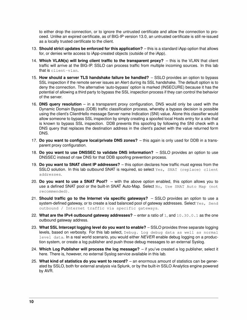
Step 4: Add a Receive Only security service
A Receive Only device is one in which traffic does not pass through it, but that a copy of the traffic flowsto it. The most common type of receive only, or “passive”, or “tap” device is an Intrusion Detection System(IDS), but other security devices can also be passive. For example, Symantec has a DLP product thatruns as a passive device. In this lab, an Ubuntu 14.0 LTS server is equipped with a single eth1 interfacewith no IP address, and that interface connects to the BIG-IP on interface 1.5. The lab is also alreadyconfigured with the VLAN and self-IP of 10.50.0.100/24. Follow these steps to create a receive onlysecurity device:
1. On the Receive Only Services tab of the SSL Orchestrator configuration, click the Add button.
2. Give the receive only service a name, example ids1.
3. In the Mac Address field, enter the layer 2 address of the passive device, which in this case will be2c:c2:60:6e:cf:a2.
4. In the IP Address field, enter an arbitrary IP address in the pre-established passive device VLANself-IP subnet, which in this case could be 10.50.0.5.
5. In the VLAN list, select the associated /Common/tap-vlan VLAN.
6. In the Interface list, select the associated interface, which in this case is 1.5.
7. Click the Finished button.
Step 5: Add an ICAP security services
An ICAP device is a security product that performs Data Loss Prevention (DLP) functions, and possiblymalware detection by way of the ICAP protocol. ICAP functions by essentially “wrapping” a payload (usuallyHTTP) with ICAP request and header information, and then sending that to an ICAP service. The ICAPservice can again perform many services, including DLP and malware detection, and summarily eitherreturn the payload untouched, modify the data (remove the sensitive information and/or malware payload),or block and sever the connection. This can apply to both request (client-to-server) and response (server-to-client) payloads. In this lab an Ubuntu 14.04 LTS server is equipped with the open source c-icap serviceand Squid and Clamav services to both facilitate access to c-icap and provide virus/malware detection.Follow these steps to create an ICAP security service:
1. On the ICAP Services tab of the SSL Orchestrator configuration, click the Add button.
2. Give the ICAP service a name, example icap1.
3. In the ICAP Devices section, provide the IP address and listening port for the ICAP service, whichin this case is 10.70.0.10, port 1344. Click the Add button to the right.
4. While not required for this lab, you have the option in the Headers list to insert custom headers onthe way to the ICAP service.
5. In the TCP Connections list, select the desired connection behavior.
6. In the Request and Response field, enter the ICAP service’s specific URL. This will be different forevery ICAP product (example: McAfee often uses the /REQMOD and /RESPMOD URLs). In this labwe’ll use the same Squid/Clamav service URL for request and response:
11
icap://${SERVER\_IP}:${SERVER\_PORT}/squidclamav
The ${SERVER_IP} and ${SERVER_PORT} strings represent a variable substitution function to allowICAP to be load balanced across a defined set of ICAP services.
7. In the Preview Max. Length (bytes) field, enter a byte value. This is the amount of data thatneeds to be sent to the ICAP service, and of course the larger this number the more latency theservice incurs. In this lab Squid/Clamav requires a preview size of 1048576.
8. In the Server Failure Handling list, select the desired behavior if the ICAP service becomesunavailable.
9. On the Send HTTP/1.0 Requests to ICAP list, select whether to send both HTTP/1.1 andHTTP/1.0 requests (Yes), or only HTTP/1.1 requests (No). Squid/Clamav will function with eitherselection.
10. Click the Finished button.
Step 6: Add inline security services
An inline device is one in which traffic flows through it, generally with separate inbound and outboundinterfaces. The current SSLO does not support one-armed devices, so any inline security device mustinclude either separate interfaces, or a single multi-tagged interface.
1. What is the IPv4 (CIDR/19) subnet block base address? – the current SSLO platforms restrictlayer 3 inline devices to a set of RFC2544 /25 (mask 255.255.255.128) in the 198.19.x.0 addressspace. This option provides some minimal capabilities to change that, but consider this. While itmay seem counterintuitive to make this restriction, consider that prior to any SSL visibility solution,most enterprises 1) already have security devices in the network, and 2) those devices are pluggedinto existing networks along with other devices. When an SSL visibility solution is introduced intothat environment, devices that previously only saw encrypted traffic are now being fed unencryptedpayloads. If that devices remains plugged into existing environments with other devices, there is ahigh probability that some of those devices will be able to see that unencrypted traffic as well. In otherwords, it is a security best practice to now isolate security devices within an SSL visibility solution. Allaccess into and out of that device, including management access, should be controlled by that SSLvisibility product. To that end, it should make no difference what the IP addresses are on that securitydevice, so changing them to suit the iApp’s requirements should not pose a significant challenge. Inthis lab, the one inline layer 3 device has an inbound eth1 interface listening on 198.19.1.64/25,an outbound interface listening on 198.19.1.130/25, and a default gateway of 198.19.1.245,which will be a BIG-IP self-IP on the destination VLAN side of that inline layer 3 device.
2. Create an inline layer 2 security service (simulated FireEye) – follow these steps to create theinline layer 2 security device definition:
• On the Inline Services tab of the SSL Orchestrator configuration, click the Add button.
• Give the inline layer 2 security service a name, example: FireEye.
• Select Layer 2 from the Service Type list.
• In the Interfaces area, select the inbound interface first (traffic going to the security device),which in this case is 1.7. Next select the outbound interface (traffic coming back to the BIG-IP),which in this case in 1.8. Whether VLAN tags are needed or not, enter tag values in the inboundand outbound tag field and then click the Add button to the right.
12
• From the Translate Port for HTTP Traffic list, select a translation port. This will bethe port, as required, that decrypted (HTTP) traffic will be translated to as it passes through thesecurity device. This setting is completely optional, but for demonstration, select Yes to Port8080.
• From the Connection Handling on Outage list, select the action you desire in the eventthat the layer 3 security device becomes unavailable.
• Click the Finished button.
3. Create an inline layer 3 security service (simulated Palo Alto NGFW) – follow these steps tocreate the inline layer 3 security device definition:
• On the Inline Services tab of the SSL Orchestrator configuration, click the Add button.
• Give the inline layer 3 security service a name, example: NGFW.
• Select Layer 3 from the Service Type list.
• In the Interfaces area, select the inbound interface first (traffic going to the security device),which in this case is 1.4 (VLAN tag 50). Next select the outbound interface (traffic comingback to the BIG-IP), which in this case is 1.4 (VLAN tag 60).
• In the Available Devices area, select 198.19.1.64 (the inbound interface of the lab layer3 device), and then click the Add button to the right.
• From the Translate Port for HTTP Traffic list, select a translation port. This will bethe port, as required, that decrypted (HTTP) traffic will be translated to as it passes through thesecurity device. This setting is completely optional, but for demonstration, select Yes to Port8443.
• From the Connection Handling on Outage list, select the action you desire in the eventthat the layer 3 security device becomes unavailable.
• Click the Finished button.
Note: The 3rd octet in the in-line layer 3 service IP range is defined by the order in which the in-line device was created. For example, if the first device created was a layer 3 device, it’s IP subnetwould be 198.19.**0*.x/25*. If the first device was layer 2, and the second layer 3, the IP subnetfor the layer 3 device would be 198.19.**1*.x/25*. A third device would be in the 198.19.**2*.x/25*subnet, etc. The in-line layer 3 security device in this lab uses the 198.19.1.x/25 subnet range,so it must be the second in-line device created in the SSLO configuration.
Step 7: Save and deploy the configuration
In this lab you’ll just be defining the services without creating any specific service chains or classifiers. All ofthe defined services automatically populate a built-in ‘All’ chain, and the default action is to send decryptedtraffic through this chain if there are not specific traffic classifier matches (which there won’t be yet). Clickthe Save button in the upper right, and then click the Deploy button. This should return a green buttonand a message that indicates the deployment was a success. If that doesn’t happen, analyze the error andre-review the steps outlined in this lab. If all else fails, skip directly to Lab 3 and use the tools listed there totroubleshoot this configuration.
Step 8: Test
Assuming the deployment was successful, open a browser on the lab Windows client and test accessingremote sites. You should see unfettered access to Internet sites, and HTTPS sites with locally re-issued
13
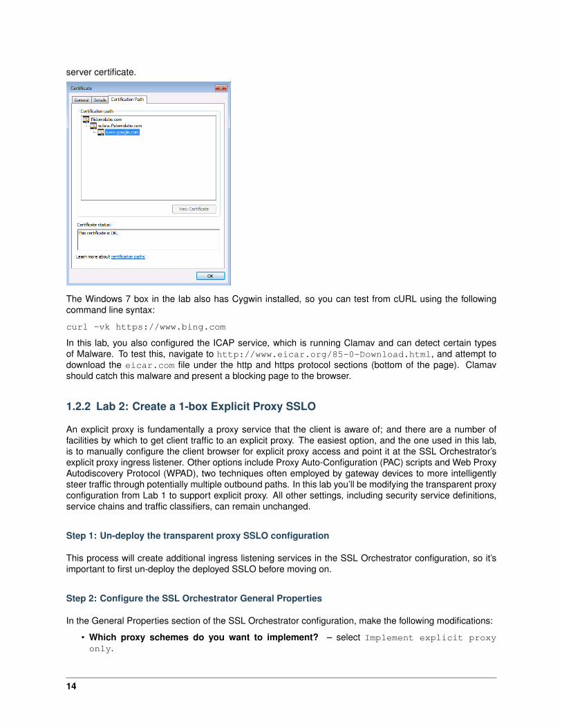
server certificate.
The Windows 7 box in the lab also has Cygwin installed, so you can test from cURL using the followingcommand line syntax:
curl -vk https://www.bing.com
In this lab, you also configured the ICAP service, which is running Clamav and can detect certain typesof Malware. To test this, navigate to http://www.eicar.org/85-0-Download.html, and attempt todownload the eicar.com file under the http and https protocol sections (bottom of the page). Clamavshould catch this malware and present a blocking page to the browser.
1.2.2 Lab 2: Create a 1-box Explicit Proxy SSLO
An explicit proxy is fundamentally a proxy service that the client is aware of; and there are a number offacilities by which to get client traffic to an explicit proxy. The easiest option, and the one used in this lab,is to manually configure the client browser for explicit proxy access and point it at the SSL Orchestrator’sexplicit proxy ingress listener. Other options include Proxy Auto-Configuration (PAC) scripts and Web ProxyAutodiscovery Protocol (WPAD), two techniques often employed by gateway devices to more intelligentlysteer traffic through potentially multiple outbound paths. In this lab you’ll be modifying the transparent proxyconfiguration from Lab 1 to support explicit proxy. All other settings, including security service definitions,service chains and traffic classifiers, can remain unchanged.
Step 1: Un-deploy the transparent proxy SSLO configuration
This process will create additional ingress listening services in the SSL Orchestrator configuration, so it’simportant to first un-deploy the deployed SSLO before moving on.
Step 2: Configure the SSL Orchestrator General Properties
In the General Properties section of the SSL Orchestrator configuration, make the following modifications:
• Which proxy schemes do you want to implement? – select Implement explicit proxyonly.
14
• On which VLAN(s) should the explicit proxy listen? – select the client side inbound VLAN.
• What IPv4 address and port should the explicit proxy use? – enter an IP address in the client sideinbound VLAN subnet, which in this case is 10.20.0.0/24. So for example, 10.20.0.150 and thecommon explicit proxy port 3128 or 8080.
• Click the Finished button.
Step 3: Save and deploy the configuration
Click the Save button and then the Deploy button. This will create an additional ingress listener on the IPv4address and port specified above.
Step 4: Test
On a browser on the Windows client desktop, change the browser’s proxy settings to match the IPv4 addressand port defined above, and then test outbound access.
You can also test from cURL using the following command line syntax:
curl -vk --proxy 10.20.0.150:3128 https://www.bing.com
1.2.3 Lab 3: Create custom Service Chains
F5 has been a market leader in SSL/TLS technologies for many years, so it should come as no real surpriseto hear that the most powerful attribute of the SSL Orchestrator is not actually SSL, but rather the advancednetworking “orchestration” capabilities of the BIG-IP full proxy architecture. All of the competitors in the SSLvisibility space can re-issue (i.e. “forge”) server certificates, and most these days can handle Perfect For-ward Secrecy. But very few have the fundamental qualities necessary to pull off intelligent service chaining.Let’s then define what service chaining really means. Essentially, it is the ability to intelligently assign, andre-use security services across multiple decrypted/inspect-able traffic flows based on the characteristics ofthose flows. Service chaining includes the ability to:
• Load balance security services
• Monitor those security services and potentially skip them if they fail
• Independently port translate across those security services
• Assign and re-use a service in multiple “chains”
• Steer “inspect-able” traffic through different chains based on attributes of a discreet packet
The implementation of service chaining manifests as three core functions of the SSL Orchestrator product:
• Defining security services – this is an exercise you’ve already completed if you went through Lab 1.It is the declaration of the service devices, inputs and outputs, and additional options specific to thatservice.
• Creating meaningful chains of security services – a chain is a list of defined services throughwhich inspect-able traffic should flow. You might, for example, have a chain dedicated to all HTTPtraffic that could include passive, ICAP, L2 and L3 inline services, or traffic originating from or goingto some address space that includes passive and L3 inline services, or traffic that meets some otherbusiness need that just includes a passive security service. You’ll create these chains as namedobjects that will be referenced from traffic classifiers.
15
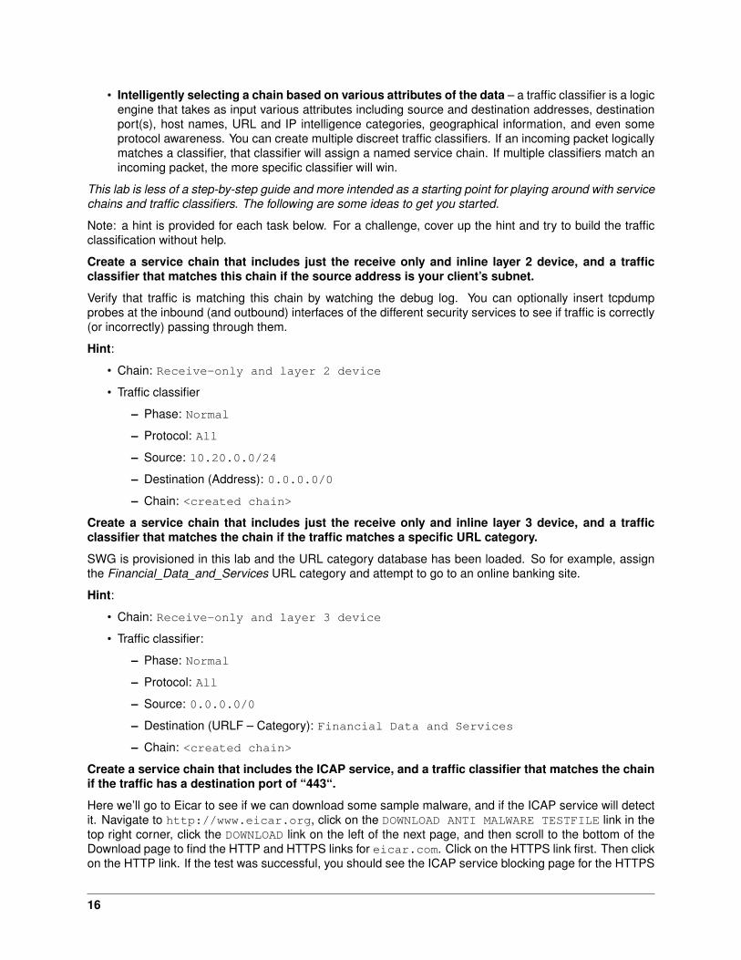
• Intelligently selecting a chain based on various attributes of the data – a traffic classifier is a logicengine that takes as input various attributes including source and destination addresses, destinationport(s), host names, URL and IP intelligence categories, geographical information, and even someprotocol awareness. You can create multiple discreet traffic classifiers. If an incoming packet logicallymatches a classifier, that classifier will assign a named service chain. If multiple classifiers match anincoming packet, the more specific classifier will win.
This lab is less of a step-by-step guide and more intended as a starting point for playing around with servicechains and traffic classifiers. The following are some ideas to get you started.
Note: a hint is provided for each task below. For a challenge, cover up the hint and try to build the trafficclassification without help.
Create a service chain that includes just the receive only and inline layer 2 device, and a trafficclassifier that matches this chain if the source address is your client’s subnet.
Verify that traffic is matching this chain by watching the debug log. You can optionally insert tcpdumpprobes at the inbound (and outbound) interfaces of the different security services to see if traffic is correctly(or incorrectly) passing through them.
Hint:
• Chain: Receive-only and layer 2 device
• Traffic classifier
– Phase: Normal
– Protocol: All
– Source: 10.20.0.0/24
– Destination (Address): 0.0.0.0/0
– Chain: <created chain>
Create a service chain that includes just the receive only and inline layer 3 device, and a trafficclassifier that matches the chain if the traffic matches a specific URL category.
SWG is provisioned in this lab and the URL category database has been loaded. So for example, assignthe Financial_Data_and_Services URL category and attempt to go to an online banking site.
Hint:
• Chain: Receive-only and layer 3 device
• Traffic classifier:
– Phase: Normal
– Protocol: All
– Source: 0.0.0.0/0
– Destination (URLF – Category): Financial Data and Services
– Chain: <created chain>
Create a service chain that includes the ICAP service, and a traffic classifier that matches the chainif the traffic has a destination port of “443“.
Here we’ll go to Eicar to see if we can download some sample malware, and if the ICAP service will detectit. Navigate to http://www.eicar.org, click on the DOWNLOAD ANTI MALWARE TESTFILE link in thetop right corner, click the DOWNLOAD link on the left of the next page, and then scroll to the bottom of theDownload page to find the HTTP and HTTPS links for eicar.com. Click on the HTTPS link first. Then clickon the HTTP link. If the test was successful, you should see the ICAP service blocking page for the HTTPS
16
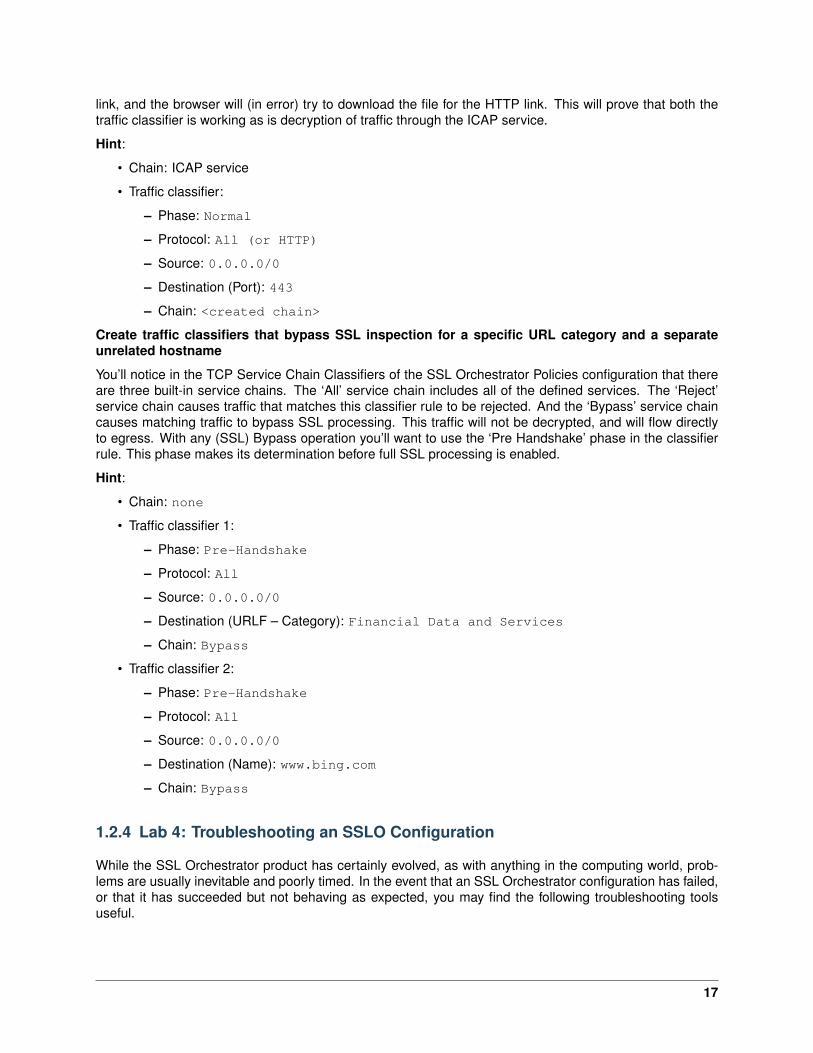
link, and the browser will (in error) try to download the file for the HTTP link. This will prove that both thetraffic classifier is working as is decryption of traffic through the ICAP service.
Hint:
• Chain: ICAP service
• Traffic classifier:
– Phase: Normal
– Protocol: All (or HTTP)
– Source: 0.0.0.0/0
– Destination (Port): 443
– Chain: <created chain>
Create traffic classifiers that bypass SSL inspection for a specific URL category and a separateunrelated hostname
You’ll notice in the TCP Service Chain Classifiers of the SSL Orchestrator Policies configuration that thereare three built-in service chains. The ‘All’ service chain includes all of the defined services. The ‘Reject’service chain causes traffic that matches this classifier rule to be rejected. And the ‘Bypass’ service chaincauses matching traffic to bypass SSL processing. This traffic will not be decrypted, and will flow directlyto egress. With any (SSL) Bypass operation you’ll want to use the ‘Pre Handshake’ phase in the classifierrule. This phase makes its determination before full SSL processing is enabled.
Hint:
• Chain: none
• Traffic classifier 1:
– Phase: Pre-Handshake
– Protocol: All
– Source: 0.0.0.0/0
– Destination (URLF – Category): Financial Data and Services
– Chain: Bypass
• Traffic classifier 2:
– Phase: Pre-Handshake
– Protocol: All
– Source: 0.0.0.0/0
– Destination (Name): www.bing.com
– Chain: Bypass
1.2.4 Lab 4: Troubleshooting an SSLO Configuration
While the SSL Orchestrator product has certainly evolved, as with anything in the computing world, prob-lems are usually inevitable and poorly timed. In the event that an SSL Orchestrator configuration has failed,or that it has succeeded but not behaving as expected, you may find the following troubleshooting toolsuseful.
17
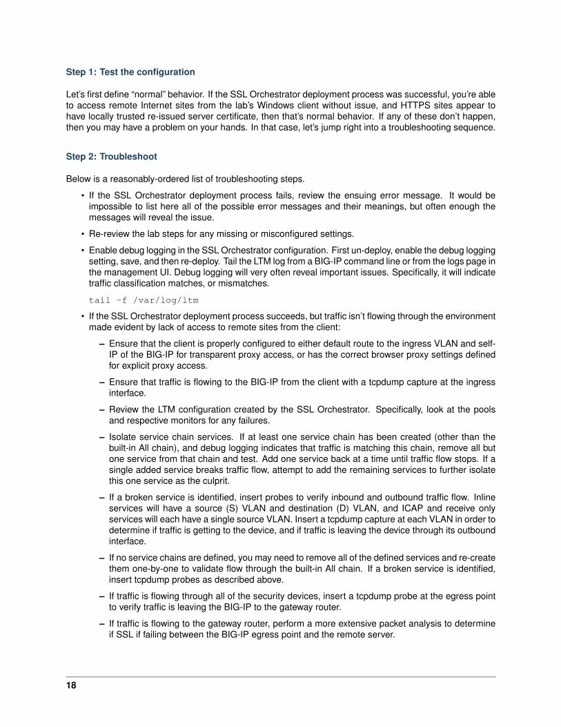
Step 1: Test the configuration
Let’s first define “normal” behavior. If the SSL Orchestrator deployment process was successful, you’re ableto access remote Internet sites from the lab’s Windows client without issue, and HTTPS sites appear tohave locally trusted re-issued server certificate, then that’s normal behavior. If any of these don’t happen,then you may have a problem on your hands. In that case, let’s jump right into a troubleshooting sequence.
Step 2: Troubleshoot
Below is a reasonably-ordered list of troubleshooting steps.
• If the SSL Orchestrator deployment process fails, review the ensuing error message. It would beimpossible to list here all of the possible error messages and their meanings, but often enough themessages will reveal the issue.
• Re-review the lab steps for any missing or misconfigured settings.
• Enable debug logging in the SSL Orchestrator configuration. First un-deploy, enable the debug loggingsetting, save, and then re-deploy. Tail the LTM log from a BIG-IP command line or from the logs page inthe management UI. Debug logging will very often reveal important issues. Specifically, it will indicatetraffic classification matches, or mismatches.
tail -f /var/log/ltm
• If the SSL Orchestrator deployment process succeeds, but traffic isn’t flowing through the environmentmade evident by lack of access to remote sites from the client:
– Ensure that the client is properly configured to either default route to the ingress VLAN and self-IP of the BIG-IP for transparent proxy access, or has the correct browser proxy settings definedfor explicit proxy access.
– Ensure that traffic is flowing to the BIG-IP from the client with a tcpdump capture at the ingressinterface.
– Review the LTM configuration created by the SSL Orchestrator. Specifically, look at the poolsand respective monitors for any failures.
– Isolate service chain services. If at least one service chain has been created (other than thebuilt-in All chain), and debug logging indicates that traffic is matching this chain, remove all butone service from that chain and test. Add one service back at a time until traffic flow stops. If asingle added service breaks traffic flow, attempt to add the remaining services to further isolatethis one service as the culprit.
– If a broken service is identified, insert probes to verify inbound and outbound traffic flow. Inlineservices will have a source (S) VLAN and destination (D) VLAN, and ICAP and receive onlyservices will each have a single source VLAN. Insert a tcpdump capture at each VLAN in order todetermine if traffic is getting to the device, and if traffic is leaving the device through its outboundinterface.
– If no service chains are defined, you may need to remove all of the defined services and re-createthem one-by-one to validate flow through the built-in All chain. If a broken service is identified,insert tcpdump probes as described above.
– If traffic is flowing through all of the security devices, insert a tcpdump probe at the egress pointto verify traffic is leaving the BIG-IP to the gateway router.
– If traffic is flowing to the gateway router, perform a more extensive packet analysis to determineif SSL if failing between the BIG-IP egress point and the remote server.
18
tcpdump -i 0.0:nnn -nn -Xs0 -vv -w <file.pcap> <any additionalfilters>
Then either export this capture to WireShark are send to ssldump:
ssldump -nr <file.pcap> -H -S crypto > text-file.txt
– If the WireShark or ssldump analysis verifies an SSL issue:
* Plug the site’s address into the SSLLabs.com server test site at:
https://www.ssllabs.com/ssltest/
This report will indicate any specific SSL requirements that this site has.
* Verify that the SSL Orchestrator server SSL profiles (two of them) have the correct cipherstring to match the requirements of this site. To do that, perform the following command atthe BIG-IP command line:
tmm --clientciphers <CIPHER STRING AS DISPLAYED IN SERVER SSLPROFILES>
* Further SSL/TLS issues are beyond the depth of this lab guide. Seek assistance.
• If all else fails, seek assistance.
1.3 Appendix - Common Testing Commands
The following are some simple, but powerful commands that are useful in developing and troubleshootingSSL visibility projects.
Controlling the SSLFWD certificate cache
The behavior of the SSL Forward Proxy changes after a certificate is cached, which will make it difficult totroubleshoot some issues. The following allows you to both list and delete the certificates in the cache.
tmsh show ltm clientssl-proxy cached-certs clientssl-profile [CLIENTSSLPROFILE] virtual [INGRESS TCP VIP]
tmsh delete ltm clientssl-proxy cached-certs clientssl-profile [CLIENTSSLPROFILE] virtual [INGRESS TCP VIP]
Isolating SSLO traffic
Any given website will be full of images, scripts, style sheets, and very often references to document objectson other sites (like a CDN). This can make troubleshooting very complex. The following cURL commandsallow you to isolate traffic to a single request and response.
curl -vk https://www.bing.com
curl -vk --proxy 10.1.10.150:3128 https://www.bing.com/
curl -vk --proxy 10.1.10.150:3128 --location https://www.bing.com/
Optionally, between each cURL test, delete the certificate cache and start logging:
tmsh delete ltm clientssl-proxy cached-certs clientssl-profile [CLIENTSSLPROFILE] virtual [INGRESS TCP VIP] && tail -f /var/log/ltm
Debugging
There is simply nothing better than debug logging for troubleshooting SSL intercept issues. The SSL Or-chestrator in debug mode pumps out an enormous set of logs, describing every step along a connection’spath. Remember to never leave debug logging enabled.
19
tail -f /var/log/ltm
Packet capture
Second only to debug logging, packet captures are crucial to troubleshooting any network-dependent issue.
tcpdump -lnni [VLAN] [-Xs0]
In-line services create “source” (S) and “destination” (D) VLANs, and ICAP and receive-only services attachto existing VLANs. Drop a probe at each point in the path and observe flow.
SSL inspection
ssldump -AdNd -i [VLAN] port 443 <and additional filters>
tcpdump -i 0.0:nnn -nn -Xs0 -vv -w <file.pcap> <and additional filters>
ssldump -nr <file.pcap> -H -S crypto > text-file.txt
TLS is rarely the issue, but a sight or configuration error may render some sites inaccessible.
Controlling the URL Filtering database
To show the current status of the database:
tmsh list sys url-db download-result
To initiate (force) the URL DB to update:
tmsh modify sys url-db download-schedule all status true download-now true
To verify that the URL DB is actively updating:
tcpdump -lnni 0.0 port 80 and host 204.15.67.80
External testing
Plug the site’s address into SSLLabs.com server test site at https://www.ssllabs.com/ssltest/ tosee if the site has any unusual SSL/TLS requirements.
20


![IP Sub Sup Netting F5[1]Tarun](https://img.pdfslide.net/doc/110x75/5452ea1baf79590c308b5246/ip-sub-sup-netting-f51tarun.jpg)