Embed Size (px)
Citation preview

VIBRATORY FEEDERSFABRICATED EQUIPMENT
1
PRODUCT OVERVIEW
IDEAL FOR...
TAILORED ON DEMAND
The Cleveland Vibrator Company offers a wide range of light, medium and heavy-duty vibratory feeders for controlling the bulk flow of materials.
Production line systems incorporating vibratory feeders can provide:
The Cleveland Vibrator Company tailors our product to the individual needs of your business. Call today to find out how we can improve your productivity and profits.
VIBRATORY FEEDERS
CF-A Air Powered Feeder • Pg. 4
Fully automated or semi-automated fill stationsFully adjustable volumetric flowLinear motion that is smooth and uniformSafety under the most hazardous conditions
••••
• CHEMICAL PLANTS
• FOOD INDUSTRY
• FOUNDRIES
• PULP & PAPER INDUSTRY
• METAL WORKING INDUSTRY
• CERAMICS INDUSTRY
• GLASS
• CHEMICAL ADDITIVE HANDLING
For the controlled flow of ingredients to mixing tanks
For chemical additive feeding in the bleaching process and chip handling systems
For the addition of binders and carbons to sand reprocessing systems
To sprinkle toppings or coatings on food and dairy products
For feeding metal parts to heat treating furnaces
For controlled ingredient flow in the batching process
For feeding glass cullet to the furnace
Such as lime or diatomaceous earth in water and sewage treatment plants
Our feeders are available in a variety of trough shapes. Units can be furnished with special trough coatings such as neoprene, UHMW, urethane, non-stick polymer, non-stick textured surfaces or removable abrasive-resistant steel plate.
The trough can be furnished in steel or polished stain-less steel to meet the most demanding requirements.
SALES DEPARTMENT • 1-800-221-3298
2
DISCHARGE OPTIONS
EQUIPMENT OPTIONS
CONTROL OPTIONS
ISOLATION OPTIONS
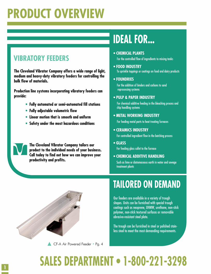
TRAY SHAPESDRIVE LOCATIONSVibratory feeder capacity will vary with tray configuration. A tubular or vee-shaped tray will not move the same volume as a standard flat tray. Consult factory for capacity data on tubular or vee-shaped output.
The standard below-deck mounting of air or electric vibrators is the most widely used.
Side mounting of drives is also avail-able for the EMF series with dual rotary electric drives.
Where installation requirements dictate, the above-deck mounting can also be used.
Call our sales department for more detailed information.
Flat
Below-Deck
Side-Mount
Above-Deck
Flared
Tubular
Vee
• Standard Flat Chute • Tapered Chute• Circular Outlet • Side Discharge
• Leveling Gate • Liners• Dust Covers • Impact Plates
• Electro-Mechanical
• Air Powered
• Electromagnetic
• Special Controls
Magnetic Starter • Variable Frequency • Dynamic Brake
Filter Regulator Lubricator • Explosion-Proof Solenoid
Variable Amplitude
Remote Operation • Two-Speed • Batch Weighing • Multiple Feeder
• Air Mounts • Rubber-In Shear• Coil Springs • Marsh-Mellow® Mounts
3
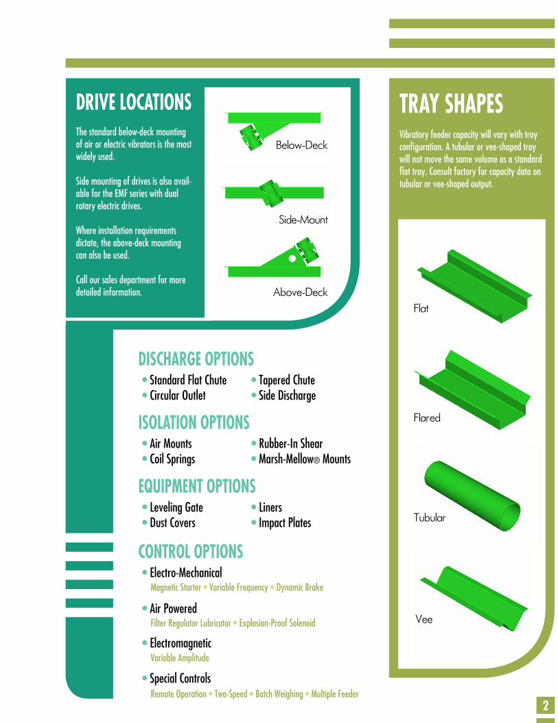
MATERIAL WEIGHT(POUNDS PER CUBIC FOOT) 25 30 35 40 45 50 55 60 70 80 90 100 125 150 175 200
CVC DENSITY FACTOR 4.0 3.3 2.9 2.5 2.2 2.0 1.8 1.7 1.4 1.3 1.1 1.0 0.8 0.7 0.6 0.5
OPERATION PRINCIPLES
Actual Particle Movement
Theoretical Movement
Line of
AmplitudeAmplitu
de of V
ibration
InertiaTravel
The power, or motivating source, is attached to the feeder tray at a prescribed angle. This angle will vary due to the physical character-istics of the product.
The entire feeder, being either suspended or on isolation mounts, is moved forward and upward, which also moves the material for-ward and upward. The tray then returns back to its original position. However, the material does not move backward due to the slower action of gravity.
This gives the material a slightly advanced position before the process repeats itself, moving the material forward in a series of rapid hops that are imperceptible to the eye.
The tons-per-hour capacity of our feeders is based on the flow of dry sand that weighs 100 lbs. per cubic foot. To better utilize the charts in this catalog, follow these simple steps to determine the actual capacity for your product.
1 • Determine your desired output of material in tons-per-hour (TPH).
2 • Determine the weight of your material in pounds per cubic foot.
3 • Use the chart below to determine the CVC density factor.
4 • Multiply your required capacity by the CVC density factor
EXAMPLE
30 × 1.7 = 51 tons per hour
While the material appears to move in a uniform flowing stream, in reality the material makes a series of short, continuous, rapid hops forward that are imperceptible to the eye.
You need to move 30 tons-per-hour of a material that weighs 60 lbs. per cubic foot. On the chart, the CVC density factor for material weighing 60 lbs. per cubic foot is 1.7. Simply multiply the desired output (30) by the found CVC density factor (1.7) to determine your products equivalent to the normal capacities shown in the catalog charts.
To move 30 tons-per-hour of your material, you would need a machine that can handle 51 tons-per-hour of sand. Don’t hesitate to call our sales department for assistance at 1-800-221-3298.
4
MODELNUMBER
ATRAY
WIDTH
BTRAY
LENGTHC D E F G H I J K NORMAL
CAPACITY
CF-A - 100 1 ½” 12” 2” 1” 8” 2 ½” 10” 7” 6 ¼” 4” 8” 1250 lbs./hr.
CF-A - 125 3” 18” 6” 1 ½” 9” 4” 12” 7 ½” 6 ¾” 4 ½” 10” 2 tons/hr.
CF-A - 200 5” 24” 8” 2 ½” 11” 6 ½” 16” 8 ½” 7 ¾” 5 ½” 14” 5 tons/hr.
CF-A - 300 6” 30” 10” 4” 16” 8” 20” 12” 11 ¾” 7 ½” 16” 8 tons/hr.
CF-A - 350 10” 36” 14” 4” 17” 12” 22” 13” 13 ¾” 9 ¼” 18” 15 tons/hr.
MODELNUMBER
ATRAY
WIDTH
BTRAY
LENGTHC D E F G H I J K L NORMAL
CAPACITY
CF-A - 400 14” 36” 6” 6” 23” 25” 30” 26” 21” 17” 6 ½” 17” 30 tons/hr.
CF-A - 500 18” 30” 11” 6” 25 ½” 30” 24” 20” 26” 22” 11” 19 ½” 50 tons/hr.
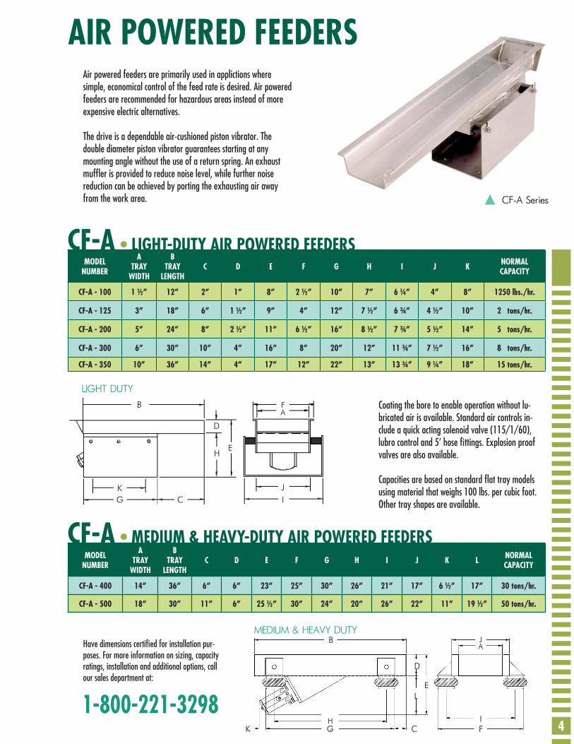
AIR POWERED FEEDERS
CF-A
CF-A
• LIGHT-DUTY AIR POWERED FEEDERS
• MEDIUM & HEAVY-DUTY AIR POWERED FEEDERS
Air powered feeders are primarily used in applictions where simple, economical control of the feed rate is desired. Air powered feeders are recommended for hazardous areas instead of more expensive electric alternatives.
The drive is a dependable air-cushioned piston vibrator. The double diameter piston vibrator guarantees starting at any mounting angle without the use of a return spring. An exhaust muffler is provided to reduce noise level, while further noise reduction can be achieved by porting the exhausting air away from the work area.
Coating the bore to enable operation without lu-bricated air is available. Standard air controls in-clude a quick acting solenoid valve (115/1/60), lubro control and 5’ hose fittings. Explosion proof valves are also available.
Capacities are based on standard flat tray models using material that weighs 100 lbs. per cubic foot. Other tray shapes are available.
Have dimensions certified for installation pur-poses. For more information on sizing, capacity ratings, installation and additional options, call our sales department at:
1-800-221-3298
CF-A Series
LIGHT DUTYB
K J
AF
G C I
H
D
E
MEDIUM & HEAVY DUTY
K G C FI
LE
D
B
H
JA
PROJECTED HORIZONTALOPENING
5
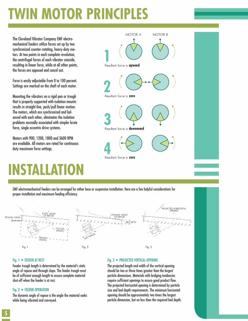
TWIN MOTOR PRINCIPLES
INSTALLATIONEMF electromechanical feeders can be arranged for either base or suspension installation. Here are a few helpful considerations for proper installation and maximum feeding efficiency.
The Cleveland Vibrator Company EMF electro-mechanical feeders utilize forces set up by two synchronized counter-rotating, heavy-duty mo-tors. At two points in each complete revolution, the centrifugal forces of each vibrator coincide, resulting in linear force, while at all other points, the forces are opposed and cancel out.
Force is easily adjustable from 0 to 100 percent. Settings are marked on the shaft of each motor.
Mounting the vibrators on a rigid pan or trough that is properly supported with isolation mounts results in straight line, push/pull linear motion. The motors, which are synchronized and bal-anced with each other, eliminates the isolation problems normally associated with simpler brute force, single eccentric drive systems.
Motors with 900, 1200, 1800 and 3600 RPM are available. All motors are rated for continuous duty maximum force settings.
Fig. 1 • FEEDER AT RESTFeeder trough length is determined by the material’s static angle of repose and through slope. The feeder trough must be of sufficient enough length to assure complete material shut-off when the feeder is at rest.
Fig. 2 • FEEDER OPERATIONThe dynamic angle of repose is the angle the material seeks while being vibrated and conveyed.
Fig. 3 • PROJECTED VERTICAL OPENINGThe projected length and width of the vertical opening should be two or three times greater than the largest particle dimensions. Materials with bridging tendencies require sufficient openings to assure good product flow. The projected horizontal opening is determined by particle size and bed depth requirements. The minimum horizontal opening should be approximately two times the largest particle dimension, but no less than the required bed depth.
TROUGH ANGLE
TROUGHLENGTH
CUT-OFFLENGTH
STATIC ANGLEOF REPOSE
EMF FORCES
DYNAMIC ANGLEOF REPOSE
BED DEPTH
Fig. 1 Fig. 2 Fig. 3
Resultant force is upward
MOTOR A MOTOR B
Resultant force is zero
Resultant force is downward
Resultant force is zero
1
2
3
4
6
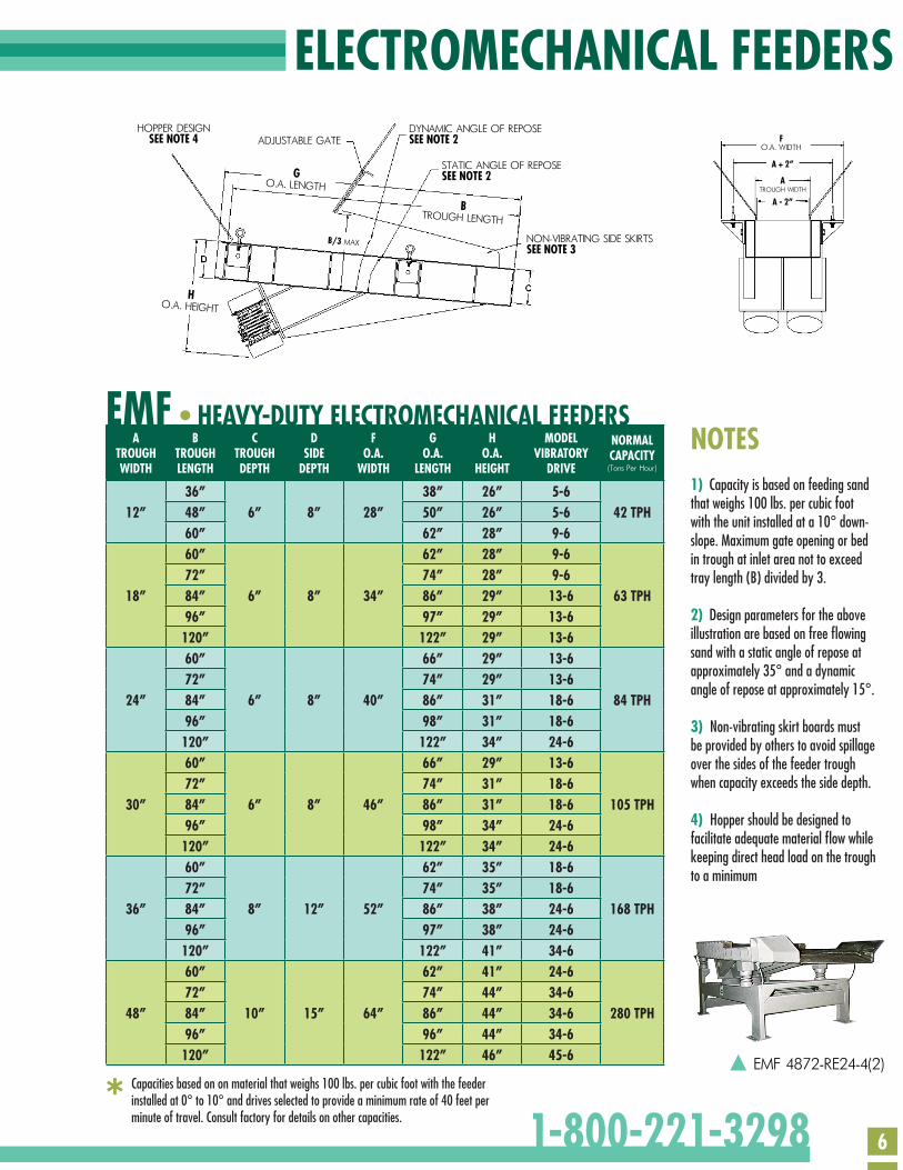
ELECTROMECHANICAL FEEDERS
ATROUGHWIDTH
BTROUGHLENGTH
CTROUGHDEPTH
DSIDE
DEPTH
FO.A.
WIDTH
GO.A.
LENGTH
HO.A.
HEIGHT
MODELVIBRATORY
DRIVE
NORMALCAPACITY(Tons Per Hour)
36” 38” 26” 5-612” 48” 6” 8” 28” 50” 26” 5-6 42 TPH
60” 62” 28” 9-660” 62” 28” 9-672” 74” 28” 9-6
18” 84” 6” 8” 34” 86” 29” 13-6 63 TPH96” 97” 29” 13-6120” 122” 29” 13-660” 66” 29” 13-672” 74” 29” 13-6
24” 84” 6” 8” 40” 86” 31” 18-6 84 TPH96” 98” 31” 18-6120” 122” 34” 24-660” 66” 29” 13-672” 74” 31” 18-6
30” 84” 6” 8” 46” 86” 31” 18-6 105 TPH96” 98” 34” 24-6120” 122” 34” 24-660” 62” 35” 18-672” 74” 35” 18-6
36” 84” 8” 12” 52” 86” 38” 24-6 168 TPH96” 97” 38” 24-6120” 122” 41” 34-660” 62” 41” 24-672” 74” 44” 34-6
48” 84” 10” 15” 64” 86” 44” 34-6 280 TPH96” 96” 44” 34-6120” 122” 46” 45-6
Capacities based on on material that weighs 100 lbs. per cubic foot with the feeder installed at 0° to 10° and drives selected to provide a minimum rate of 40 feet per minute of travel. Consult factory for details on other capacities.*
EMF 4872-RE24-4(2)
1) Capacity is based on feeding sand that weighs 100 lbs. per cubic foot with the unit installed at a 10° down-slope. Maximum gate opening or bed in trough at inlet area not to exceed tray length (B) divided by 3.
2) Design parameters for the above illustration are based on free flowing sand with a static angle of repose at approximately 35° and a dynamic angle of repose at approximately 15°.
3) Non-vibrating skirt boards must be provided by others to avoid spillage over the sides of the feeder trough when capacity exceeds the side depth.
4) Hopper should be designed to facilitate adequate material flow while keeping direct head load on the trough to a minimum
NOTES
HOPPER DESIGNSEE NOTE 4
HO.A. HEIGHT
BTROUGH LENGTH
GO.A. LENGTH
DYNAMIC ANGLE OF REPOSESEE NOTE 2
NON-VIBRATING SIDE SKIRTSSEE NOTE 3
STATIC ANGLE OF REPOSESEE NOTE 2
ADJUSTABLE GATE
B/3 MAX
FO.A. WIDTH
ATROUGH WIDTH
A + 2”
A - 2”
EMF • HEAVY-DUTY ELECTROMECHANICAL FEEDERS
1-800-221-3298
7
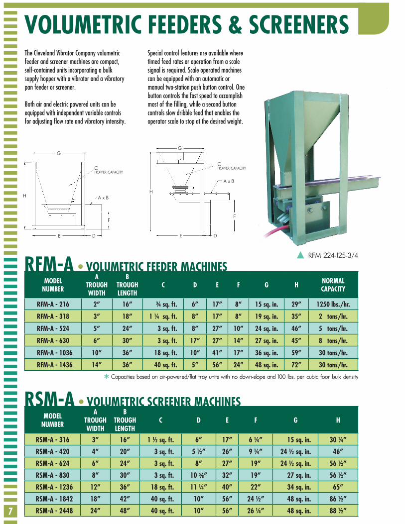
VOLUMETRIC FEEDERS & SCREENERS
MODELNUMBER
ATROUGHWIDTH
BTROUGHLENGTH
C D E F G H NORMALCAPACITY
RFM-A - 216 2” 16” ¾ sq. ft. 6” 17” 8” 15 sq. in. 29” 1250 lbs./hr.
RFM-A - 318 3” 18” 1 ¼ sq. ft. 8” 17” 8” 19 sq. in. 35” 2 tons/hr.
RFM-A - 524 5” 24” 3 sq. ft. 8” 27” 10” 24 sq. in. 46” 5 tons/hr.
RFM-A - 630 6” 30” 3 sq. ft. 17” 27” 14” 27 sq. in. 45” 8 tons/hr.
RFM-A - 1036 10” 36” 18 sq. ft. 10” 41” 17” 36 sq. in. 59” 30 tons/hr.
RFM-A - 1436 14” 36” 40 sq. ft. 5” 56” 24” 48 sq. in. 72” 30 tons/hr.
MODELNUMBER
ATROUGHWIDTH
BTROUGHLENGTH
C D E F G H
RSM-A - 316 3” 16” 1 ½ sq. ft. 6” 17” 6 ¼” 15 sq. in. 30 ¼”
RSM-A - 420 4” 20” 3 sq. ft. 5 ½” 26” 9 ¼” 24 ½ sq. in. 46”
RSM-A - 624 6” 24” 3 sq. ft. 8” 27” 19” 24 ½ sq. in. 56 ½”
RSM-A - 830 8” 30” 3 sq. ft. 10 ” 32” 19” 27 sq. in. 56 ½”
RSM-A - 1236 12” 36” 18 sq. ft. 11 ¼” 40” 22” 34 sq. in. 65”
RSM-A - 1842 18” 42” 40 sq. ft. 10” 56” 24 ½” 48 sq. in. 86 ½”
RSM-A - 2448 24” 48” 40 sq. ft. 10” 56” 26 ¼” 48 sq. in. 88 ½”
RFM-A
RSM-A
• VOLUMETRIC FEEDER MACHINES
• VOLUMETRIC SCREENER MACHINES
The Cleveland Vibrator Company volumetric feeder and screener machines are compact, self-contained units incorporating a bulk supply hopper with a vibrator and a vibratory pan feeder or screener.
Both air and electric powered units can be equipped with independent variable controls for adjusting flow rate and vibratory intensity.
Special control features are available where timed feed rates or operation from a scale signal is required. Scale operated machines can be equipped with an automatic or manual two-station push button control. One button controls the fast speed to accomplish most of the filling, while a second button controls slow dribble feed that enables the operator scale to stop at the desired weight.
Capacities based on air-powered/flat tray units with no down-slope and 100 lbs. per cubic foor bulk density
RFM 224-125-3/4
G
H
E D
A x B
CHOPPER CAPACITY
F
*
D
A x B
CHOPPER CAPACITY
F
E
H
G
5 8/
8
We maintain a testing lab where samples of customer materials can be received and tested to ensure satisfactory performance of our products.
Or test our products on-site and guarantee equipment sizing, installation, suitability and performance.
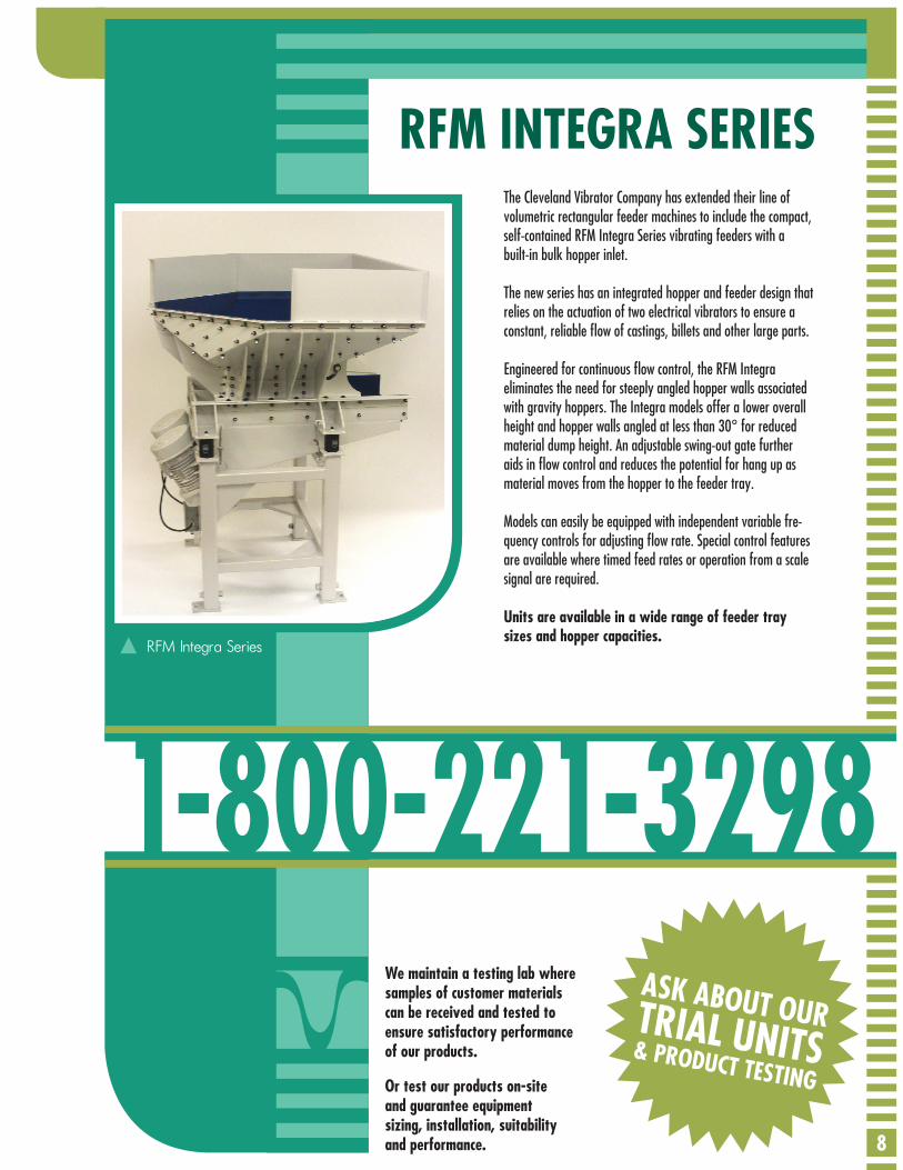
The Cleveland Vibrator Company has extended their line of volumetric rectangular feeder machines to include the compact, self-contained RFM Integra Series vibrating feeders with a built-in bulk hopper inlet.
The new series has an integrated hopper and feeder design that relies on the actuation of two electrical vibrators to ensure a constant, reliable flow of castings, billets and other large parts.
Engineered for continuous flow control, the RFM Integra eliminates the need for steeply angled hopper walls associated with gravity hoppers. The Integra models offer a lower overall height and hopper walls angled at less than 30° for reduced material dump height. An adjustable swing-out gate further aids in flow control and reduces the potential for hang up as material moves from the hopper to the feeder tray.
Models can easily be equipped with independent variable fre-quency controls for adjusting flow rate. Special control features are available where timed feed rates or operation from a scale signal are required.
Units are available in a wide range of feeder tray sizes and hopper capacities.
1-800-221-3298
RFM INTEGRA SERIES
RFM Integra Series
ASK ABOUT OUR& PRODUCT TESTING
TRIAL UNITS
9
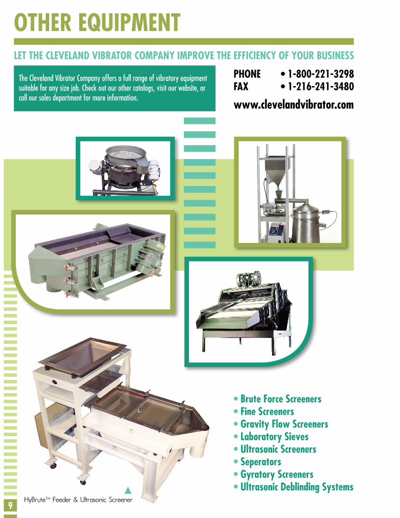
OTHER EQUIPMENTLET THE CLEVELAND VIBRATOR COMPANY IMPROVE THE EFFICIENCY OF YOUR BUSINESS
PHONE • 1-800-221-3298FAX • 1-216-241-3480
• Brute Force Screeners• Fine Screeners• Gravity Flow Screeners• Laboratory Sieves• Ultrasonic Screeners• Seperators• Gyratory Screeners• Ultrasonic Deblinding Systems
www.clevelandvibrator.com
The Cleveland Vibrator Company offers a full range of vibratory equipment suitable for any size job. Check out our other catalogs, visit our website, or call our sales department for more information.
HyBrute™ Feeder & Ultrasonic Screener
10
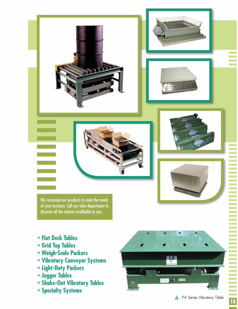
• Flat Deck Tables• Grid Top Tables• Weigh-Scale Packers• Vibratory Conveyor Systems• Light-Duty Packers• Jogger Tables• Shake-Out Vibratory Tables• Specialty Systems
FA Series Vibratory Table
We customize our products to meet the needs of your business. Call our sales department to discover all the options availbable to you.
Since 1923 Cleveland Vibrator Company has been designing, manufacturing and supplying vibratory products and offering services to meet material handling needs. Our diverse products and knowledge ranges from the precise challenges of fine powder screening to the most rugged feeder, screener and conveyor applications.
In addition to our breadth of capabilities, we dif-ferentiate ourselves with a unique focus on quality, integrity and customer service that has made us a partner with more than 15,000 organizations around the world since our opening over 85 years ago.
The Cleveland Vibrator Co.2828 Clinton AvenueCleveland, OH 44113
Phone: (800) 221-3298 (216) 241-7157Fax: (216) 241-3480


![A Solution to Contiguous and Overlapping Parts in Sensor ...faculty.csupueblo.edu/n.jaksic/Papers/IJMS94.pdfinto vibratory and nonvibratory feeders [4]. The most versatile and the](https://img.pdfslide.net/doc/110x75/60266bfce003cf1bdc3324ae/a-solution-to-contiguous-and-overlapping-parts-in-sensor-into-vibratory-and.jpg)