Embed Size (px)
Citation preview

NOT MEASUREMENTSENSITIVE
FACILITYSYSTEM SAFETY
GUIDEBOOK
NASA TECHNICAL STANDARD
NASA-STD-8719.7January 1998
National Aeronautics andSpace Administration
NASA -STD-8719.7January 1998
i
FOREWORD
Effective Date: January 30, 1998
This NASA Technical Standard (NTS) provides a guideline for NASA facility and safetyprofessionals who are involved with the facility acquisition or modification/construction processand life cycle phases at NASA installations. This document provides fundamental information forthe development of a facility safety program during the acquisition process and the framework forimplementing facility system safety goals and requirements into NASA facilities. Safety is anintegral aspect of the facility acquisition process and must be considered at all phases throughoutthe life cycle of the facility system. This document has also been developed to support the NASASafety Training Center (NSTC), “Facility System Safety Course.”
Comments regarding this document should be addressed to the Director, Safety and RiskManagement Division, NASA Headquarters, Washington, DC 20546.
Frederick D. Gregory
Associate Administrator forSafety and Mission Assurance
DISTRIBUTION:
SDL1 (SIQ)
NASA -STD-8719.7January 1998
ii
TABLE OF CONTENTS
PARAGRAPH PAGE
FOREWORD ................................................................................................... i
TABLE OF CONTENTS ................................................................................ ii
APPENDICES ............................................................................................... iii
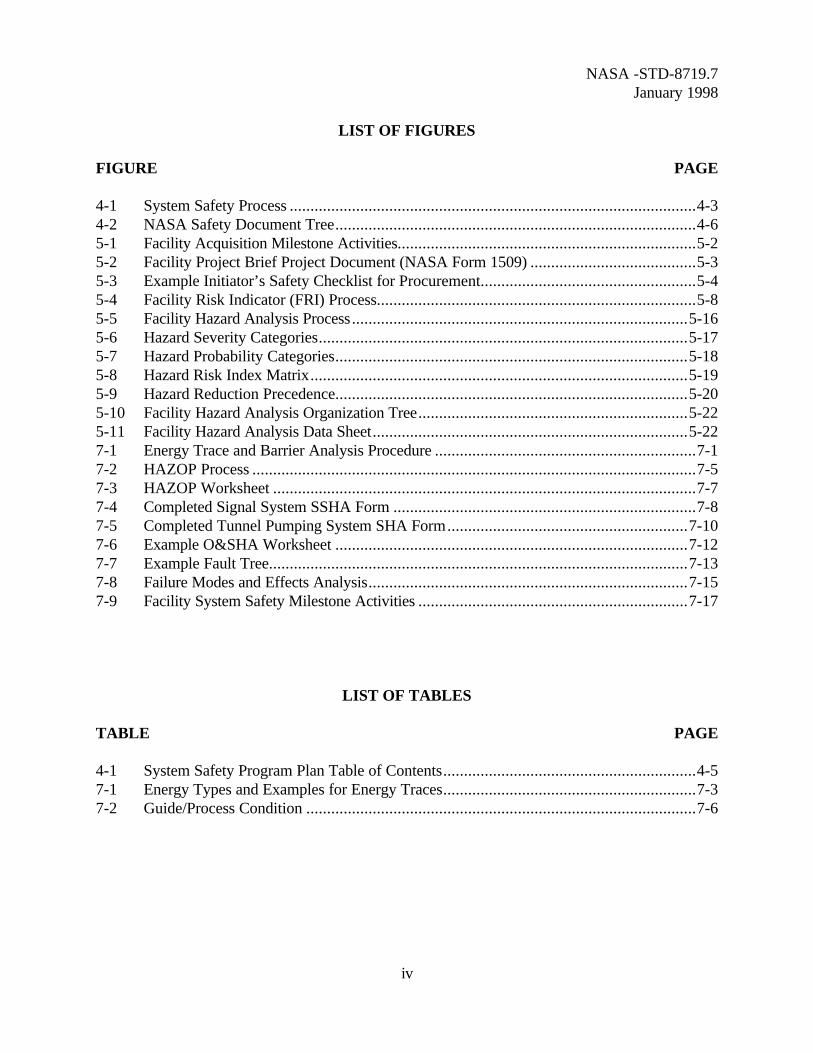
LIST OF FIGURES........................................................................................ iv
LIST OF TABLES ......................................................................................... iv
1. SCOPE1.1 Purpose ...........................................................................................1-11.2 Applicability ....................................................................................1-11.3 Organization of Handbook...............................................................1-1
2. REFERENCED DOCUMENTS2.1 Government Documents ..................................................................2-12.2 Commercial Publications..................................................................2-12.3 Order of Precedence ........................................................................2-1
3. DEFINITIONS AND ACRONYMS3.1 System Safety Definitions ................................................................3-13.2 System Safety Acronyms .................................................................3-1
4. GENERAL4.1 Introduction.....................................................................................4-14.2. Processes.........................................................................................4-24.3 NASA Safety Policy and Requirements............................................4-4
5. FACILITY SYSTEM SAFETY PROCESS5.1 Introduction.....................................................................................5-15.2 Requirements Phase.........................................................................5-15.3 Planning Phase...............................................................................5-115.4 Design Phase .................................................................................5-245.5 Construction Phase ........................................................................5-245.6 Activation Phase............................................................................5-265.7 Operations Phase ...........................................................................5-275.8 Disposal Phase...............................................................................5-27
NASA -STD-8719.7January 1998
iii
TABLE OF CONTENTS(Continued)
PARAGRAPH PAGE
6. OTHER FACILITY ACTIVITIES REQUIRING A SYSTEM SAFETY INPUT6.1 Introduction.....................................................................................6-16.2 Operating Procedures ......................................................................6-16.3 Test Activities..................................................................................6-16.4 Maintenance Procedures ..................................................................6-26.5 Facility Acceptance Plans.................................................................6-36.6 Training Plans..................................................................................6-46.7 Configuration Management Plans.....................................................6-56.8 Emergency Management Plans.........................................................6-5
7. OTHER HAZARD ANALYSIS METHODOLOGIES7.1 Introduction.....................................................................................7-17.2 Energy Trace Barrier Analysis .........................................................7-17.3 Hazard and Operability Study ..........................................................7-57.4 Subsystem Hazard Analysis..............................................................7-87.5 System Hazard Analysis...................................................................7-97.6 Operating and Support Hazard Analysis...........................................7-97.7 Fault Tree Analysis ........................................................................7-127.8 Failure Mode And Effects Analysis ................................................7-147.9 Software Hazard Analysis..............................................................7-147.10 Hazard Analysis Schedules.............................................................7-17
APPENDICES
APPENDIX PAGE
A Typical Energy Sources Checklist ................................................................ A-1B Preliminary Hazard List Example ................................................................. B-1C Example Facility Safety Management Plan - Table of Contents..................... C-1D Example Facility Hazard Analysis ................................................................ D-1
NASA -STD-8719.7January 1998
iv
LIST OF FIGURES
FIGURE PAGE
4-1 System Safety Process ..................................................................................................4-34-2 NASA Safety Document Tree.......................................................................................4-65-1 Facility Acquisition Milestone Activities........................................................................5-25-2 Facility Project Brief Project Document (NASA Form 1509) ........................................5-35-3 Example Initiator’s Safety Checklist for Procurement....................................................5-45-4 Facility Risk Indicator (FRI) Process.............................................................................5-85-5 Facility Hazard Analysis Process.................................................................................5-165-6 Hazard Severity Categories.........................................................................................5-175-7 Hazard Probability Categories.....................................................................................5-185-8 Hazard Risk Index Matrix...........................................................................................5-195-9 Hazard Reduction Precedence.....................................................................................5-205-10 Facility Hazard Analysis Organization Tree.................................................................5-225-11 Facility Hazard Analysis Data Sheet............................................................................5-227-1 Energy Trace and Barrier Analysis Procedure ...............................................................7-17-2 HAZOP Process ...........................................................................................................7-57-3 HAZOP Worksheet ......................................................................................................7-77-4 Completed Signal System SSHA Form .........................................................................7-87-5 Completed Tunnel Pumping System SHA Form..........................................................7-107-6 Example O&SHA Worksheet .....................................................................................7-127-7 Example Fault Tree.....................................................................................................7-137-8 Failure Modes and Effects Analysis.............................................................................7-157-9 Facility System Safety Milestone Activities .................................................................7-17
LIST OF TABLES
TABLE PAGE
4-1 System Safety Program Plan Table of Contents.............................................................4-57-1 Energy Types and Examples for Energy Traces.............................................................7-37-2 Guide/Process Condition ..............................................................................................7-6
NASA-STD-8719.7January 1998
1-1
CHAPTER 1: SCOPE
1.1 PURPOSE. This document is a guideline for implementing a Facility System SafetyProgram to meet the requirements of “NASA Safety Policy and Requirements Document,”NHB 1700.1 (V1B). The facility acquisition process information was taken from the “NASAFacility Project Implementation Handbook,” NPG 8820.2. The purpose of this Facility SystemSafety Guidebook is to provide a guideline for facility and safety professionals who are involvedwith the facility acquisition or modification/construction process and life cycle phases at NASAinstallations and to provide fundamental information for the development of a facility safetyprogram during the acquisition process. This guidebook provides the framework forimplementing facility system safety goals and requirements into NASA facilities. Safety is anintegral aspect of the facility acquisition process and must be considered at all phases throughoutthe life cycle of the facility system. This document has also been developed to support the NASASafety Training Center (NSTC), “Facility System Safety Course.”
1.2 APPLICABILITY. This document provides a guideline for implementing a facilitysystem safety program at all NASA Centers, Field Installations, and Component Facilities. In thisdocument, the words “Center” and “Centers” refer to all NASA Centers, Field Installations, andComponent Facilities. System safety methodologies and facility acquisition activities areintegrated to assure safety of the completed facility. The document is based on NASA facilitysystem safety requirements and many government and industry guidelines for facility safety. Techniques for completing Facility Hazard Analysis are addressed in sufficient detail to provide aworking knowledge and a basis for continued refinement of skills.
1.3 ORGANIZATION OF HANDBOOK. This handbook is organized in a standardfashion. Section 1 addresses Scope, Section 2, Referenced Documents, Section 3, Definitions andAcronyms, and Section 4, General. Sections 5 through 7 provide technical information andguidance material.
NASA-STD-8719.7January 1998
2-1
CHAPTER 2: REFERENCED DOCUMENTS
2.1 GOVERNMENT DOCUMENTS.
NASA DOCUMENTS.
National Aeronautics and Space Administration. (1982). “Safety and HealthHandbook,” NHB 2710.1. Washington, DC: U.S. Government Printing Office.
National Aeronautics and Space Administration. (1997). “Facility ProjectImplementation Handbook,” NPG 8820.2. Washington, DC: U.S. GovernmentPrinting Office.
National Aeronautics and Space Administration. (1993). “NASA Safety Policy andRequirements Document,” NHB 1700.1 (V1-B). Washington, DC: U.S. GovernmentPrinting Office.
OTHER GOVERNMENT AGENCIES.
U.S. Department of Defense. (1993). “Military Standard System Safety ProgramRequirements,” MIL-STD 882C. Washington, DC: U.S. Government Printing Office.
U.S. Department of the Army. (1988). “ Facility System Safety,” EM 385-1-1. Washington DC: U.S. Government Printing Office.
U.S. Department of the Navy. (1986). “Navy System Safety Program ,”OPNAVINST 5100.24. Washington DC: Department of the Navy.
U.S. Department of the Navy. (1987). “Command Safety and Health Program,”NAVFACINST 5100.1G. Alexandria, VA: Naval Facilities Engineering Command.
2.2 COMMERCIAL PUBLICATIONS.
Hammer, W. (1980). “Product Safety Management and Engineering.” EnglewoodCliffs, NJ: Prentice-Hall.
Olson, R.E. (1982). “System Safety Handbook for the Acquisition Manager.” LosAngeles: Space Division, U.S. Air Force Systems Command Printing Office.
Roland, H.E., & Moriarty, B. (1990). “System Safety Engineering andManagement.” New York: John Wiley and Sons, Inc.
2.3 ORDER OF PRECEDENCE. Nothing in this document supersedes applicable laws orregulations unless a specific exemption has been obtained.
NASA-STD-8719.7January 1998
3-1
CHAPTER 3: DEFINITIONS AND ACRONYMS
3.1 SYSTEM SAFETY DEFINITIONS. The following definitions are used in thispublication:
• Hazard: Any real or potential condition that can cause injury or death, or damageto or loss of equipment or property.
• Hazard Cause: Any item that creates or significantly contributes to the existence ofa hazard.
• Hazard Effects: The potential detrimental consequences of the hazard.
• Risk: The combination of the hazard severity with the likelihood of its occurrence.
3.2 SYSTEM SAFETY ACRONYMS. The following is a comprehensive list of theacronyms used in this publication:
A&E Architect EngineeringACGIH American Councils of Governmental Industrial HygienistsADA Americans with Disabilities ActASHRAE American Society of Heating, Refrigeration, and Air Conditioning EngineersASTM American Society for Testing and MaterialsCFR Code of Federal RegulationsCoF Construction of FacilitiesETBA Energy Trace Barrier AnalysisFHA Facility Hazard AnalysisFMEA Failure Modes and Effects AnalysisFRI Facility Risk IndicatorFSMP Facility Safety Management PlanHASC Hazard Analysis Sub CommitteeHATI Hazard Analysis Tracking IndexHAZOP Hazard and Operability StudyHLTR Hazard List Tracking RecordHRV Hazard Resolution VerificationIST Initial System TestNFPA National Fire Protection ActNHB NASA HandbookNIOSH National Institute of Occupational Safety and HealthNMI NASA Management InstructionNPD NASA Policy DirectiveNPG NASA Procedures and Guidelines
NASA-STD-8719.7January 1998
3-2
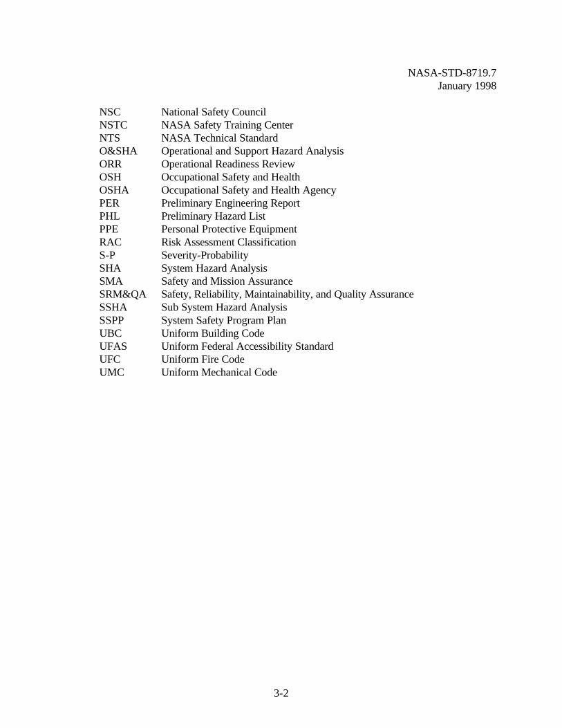
NSC National Safety CouncilNSTC NASA Safety Training CenterNTS NASA Technical StandardO&SHA Operational and Support Hazard AnalysisORR Operational Readiness ReviewOSH Occupational Safety and HealthOSHA Occupational Safety and Health AgencyPER Preliminary Engineering ReportPHL Preliminary Hazard ListPPE Personal Protective EquipmentRAC Risk Assessment ClassificationS-P Severity-ProbabilitySHA System Hazard AnalysisSMA Safety and Mission AssuranceSRM&QA Safety, Reliability, Maintainability, and Quality AssuranceSSHA Sub System Hazard AnalysisSSPP System Safety Program PlanUBC Uniform Building CodeUFAS Uniform Federal Accessibility StandardUFC Uniform Fire CodeUMC Uniform Mechanical Code
NASA-STD-8719.7January 1998
4-1
CHAPTER 4: GENERAL
4.1 INTRODUCTION
According to NASA accident/incident reports, over 50 million dollars worth of damage resultedfrom facility mishaps during the decade 1985 to 1995. At one Center, lightning struck anddamaged the Main Electrical Power Substation; poor equipment design and operational procedurefailure caused over three million dollars worth of damage. At another center, a short circuit inlighting equipment created a fire, resulting in smoke and fire damage. Single point failure in aNASA wind tunnel resulted in a catastrophic loss costing over 3 million dollars. At anotherCenter, a cooling tower collapsed and resulted in over three million dollars worth of damage. Toimprove the hazard identification and elimination/control process, NASA Headquarters hasdeveloped this handbook and a facility safety course.
4.1.1. System safety is a discipline that examines the total life cycle of a system orprocess. System safety draws professional knowledge and specialized skills in engineering,mathematical, physical, and related scientific disciplines to specify, predict, and evaluate the safetyof systems and facilities. The safety achieved in a system is dependent on the importance safety isgiven during the requirements, planning, design, construction, activation, operation, and disposalphases of each system and facility. Designing-in safety is a prerequisite and precursor foreffective operational safety. The goal is to produce an inherently safe facility that will have theappropriate level of safety controls.
4.1.2. The System Safety Concept. “Military Standard System Safety ProgramRequirements,” MIL-STD-882, defines system safety as “the application of engineering andmanagement principles, criteria, and techniques to optimize all aspects of safety within theconstraints of operational effectiveness, time, and cost throughout all phases of the system lifecycle.”
4.1.3. The goal of system safety is to optimize safety and manage the residual risks. Because safety is “the freedom from personnel injury, damage to equipment, or loss of resources(especially mission critical resources),” there are numerous system components that the engineermust consider. The principal elements are people, equipment, facilities, environment, and the timeframe. Risk management is the administration of all of these elements and optimal control of riskswithin the constraints of system operational effectiveness, schedule, and cost.
4.1.4. System safety is based on the approach of studying the entire system under allpossible operating conditions. The total system is a composite, at any level of complexity, ofpersonnel, procedures, materials, tools, equipment, facilities, and software. The elements of thiscomposite entity are used together in the intended operational or support environment to performa given task or achieve a specific production, support, or mission requirements. The systemsafety process is a systematic approach to safety program management, requirementsidentification, analysis of systems, and documentation of results throughout the entire program lifecycle.
NASA-STD-8719.7January 1998
4-2
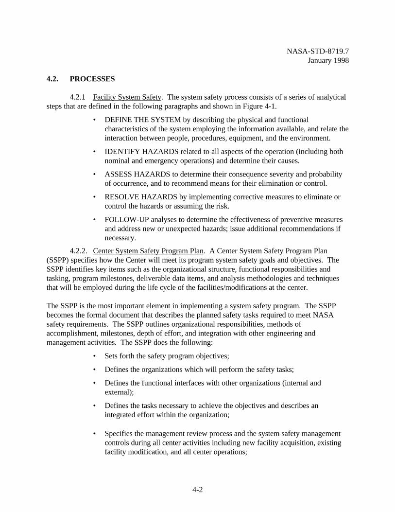
4.2. PROCESSES
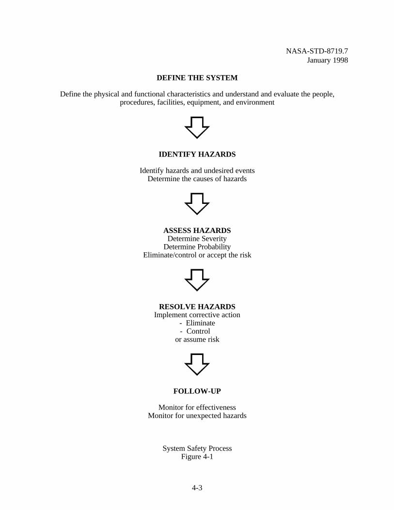
4.2.1 Facility System Safety. The system safety process consists of a series of analyticalsteps that are defined in the following paragraphs and shown in Figure 4-1.
• DEFINE THE SYSTEM by describing the physical and functionalcharacteristics of the system employing the information available, and relate theinteraction between people, procedures, equipment, and the environment.
• IDENTIFY HAZARDS related to all aspects of the operation (including bothnominal and emergency operations) and determine their causes.
• ASSESS HAZARDS to determine their consequence severity and probabilityof occurrence, and to recommend means for their elimination or control.
• RESOLVE HAZARDS by implementing corrective measures to eliminate orcontrol the hazards or assuming the risk.
• FOLLOW-UP analyses to determine the effectiveness of preventive measuresand address new or unexpected hazards; issue additional recommendations ifnecessary.
4.2.2. Center System Safety Program Plan. A Center System Safety Program Plan(SSPP) specifies how the Center will meet its program system safety goals and objectives. TheSSPP identifies key items such as the organizational structure, functional responsibilities andtasking, program milestones, deliverable data items, and analysis methodologies and techniquesthat will be employed during the life cycle of the facilities/modifications at the center.
The SSPP is the most important element in implementing a system safety program. The SSPPbecomes the formal document that describes the planned safety tasks required to meet NASAsafety requirements. The SSPP outlines organizational responsibilities, methods ofaccomplishment, milestones, depth of effort, and integration with other engineering andmanagement activities. The SSPP does the following:
• Sets forth the safety program objectives;
• Defines the organizations which will perform the safety tasks;
• Defines the functional interfaces with other organizations (internal andexternal);
• Defines the tasks necessary to achieve the objectives and describes anintegrated effort within the organization;
• Specifies the management review process and the system safety managementcontrols during all center activities including new facility acquisition, existingfacility modification, and all center operations;
NASA-STD-8719.7January 1998
4-3
DEFINE THE SYSTEM
Define the physical and functional characteristics and understand and evaluate the people,procedures, facilities, equipment, and environment
IDENTIFY HAZARDS
Identify hazards and undesired eventsDetermine the causes of hazards
ASSESS HAZARDSDetermine Severity
Determine ProbabilityEliminate/control or accept the risk
RESOLVE HAZARDSImplement corrective action
- Eliminate- Control
or assume risk
FOLLOW-UP
Monitor for effectivenessMonitor for unexpected hazards
System Safety ProcessFigure 4-1
NASA-STD-8719.7January 1998
4-4
• Describes the technical methods for conducting safety analyses during thefacility life cycle;
• Identifies any unusual safety activities that must be performed as a result ofstate of the art development or application; and
• Defines the data requirements and describes the necessary outputs.
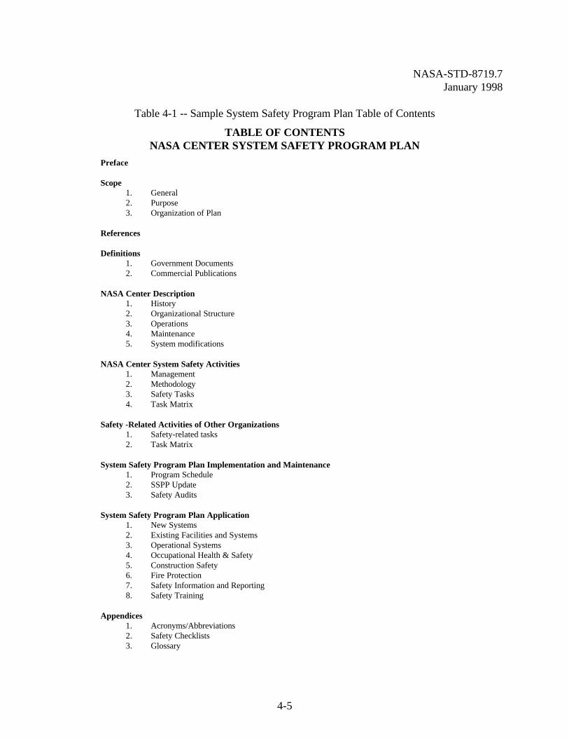
The SSPP describes in detail how to manage and accomplish the detailed system safety tasks. Forall NASA Center Directorates and contractors, the Center SSPP provides a means to understandhow facility system safety is to be accomplished, and how system safety activities will later beaudited. See Table 4-1 for a sample SSPP table of contents.
4.3 NASA SAFETY POLICY AND REQUIREMENTS
4.3.1. Roles and Responsibilities. NASA Policy Documents (NPDs) provide safetypolicy for the effective application of system safety throughout NASA. Emphasis is given tosafety research, accident investigation, risk assessment, information exchange, safety motivation,training, and appraisal. Each Center implements the policy set forth in the NMIs by developingtailored management instructions that meet the desired goals and objectives of the Center.
NASA Centers direct policy and are held accountable for the specific functions of their SystemSafety program. The goals and objectives of each Center must include safety in orbital, facility,and research programs as well as other programs. NASA establishes system safety as an integralelement of every program, starting in the requirements phase and continuing throughout thedisposal phase.
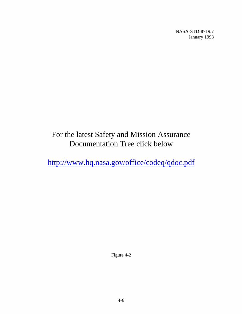
4.3.2 Requirements Documents. NASA Headquarters requires that each Center followthe requirements of “NASA Safety Policy and Requirements Document;” NHB 1700.1 (V1-B);Occupational Safety and Health Administration; and requirements of other Federal, State, andlocal regulatory agencies. A documentation tree showing the hierarchy of NASA safety relatedrequirements and guidelines is depicted in Figure 4-2.
The objective of the NASA Safety Program as outlined in the “NASA Safety Policy andRequirements Document” is "to positively effect the overall success rate for missions andoperations and to prevent injury to personnel and loss of property and/or technical reputation." The NASA Headquarters Safety and Risk Management Division (Code QS) within the Office ofSafety and Mission Assurance (SMA) has authority and responsibility for safety policy andoversight.
NASA-STD-8719.7January 1998
4-5
Table 4-1 -- Sample System Safety Program Plan Table of Contents
TABLE OF CONTENTSNASA CENTER SYSTEM SAFETY PROGRAM PLAN
Preface
Scope1. General2. Purpose3. Organization of Plan
References
Definitions1. Government Documents2. Commercial Publications
NASA Center Description1. History2. Organizational Structure3. Operations4. Maintenance5. System modifications
NASA Center System Safety Activities1. Management2. Methodology3. Safety Tasks4. Task Matrix
Safety -Related Activities of Other Organizations1. Safety-related tasks2. Task Matrix
System Safety Program Plan Implementation and Maintenance1. Program Schedule2. SSPP Update3. Safety Audits
System Safety Program Plan Application1. New Systems2. Existing Facilities and Systems3. Operational Systems4. Occupational Health & Safety5. Construction Safety6. Fire Protection7. Safety Information and Reporting8. Safety Training
Appendices1. Acronyms/Abbreviations2. Safety Checklists3. Glossary
NASA-STD-8719.7January 1998
4-6
For the latest Safety and Mission AssuranceDocumentation Tree click below
http://www.hq.nasa.gov/office/codeq/qdoc.pdf
Figure 4-2
NASA-STD-8719.7January 1998
4-7
The highest level of authority and responsibility for safety at the Center is the Center Directorwho delegates safety responsibilities at his installation. Delegated safety responsibilities includeproviding safety oversight for all activities, ensuring the safety of Center operations/programs,and implementing the provisions of “NASA Safety Policy and Requirements Document,”NHB 1700.1 (VI-B). Management Instructions are developed by each Center to define theCenter safety policy, responsibilities, and the implementation process to incorporate therequirements.
NASA Headquarters policy requires that the Safety and Mission Assurance (SMA) Directors ateach Center functionally report to the NASA Code Q/Office of Safety and Mission Assurance(SMA). The Office of SMA plans, directs, and evaluates NASA-wide SMA activities. The Officeof SMA has established a requirement to incorporate safety, reliability, and quality into programsat their earliest stage and to develop standards and guidelines tailored to meet unique programrequirements.
4.3.3 References. A list of the documents, guidelines, and good industry practices usedto implement NASA facility system safety programs are provided below. This list is notcomprehensive; however, it does include the most commonly used references at NASA Centers.
4.3.3.1. Required Documents
NASA Documents
• NHB 1700.1 (V1-B), “Safety Policy and Requirements Document”• NSS 1740.11, “Safety Standards for Fire Protection”• NHB 2710.1, “Safety and Health Handbook”• NPG 8820.2, “Facility Project Implementation Handbook”• Applicable Center Handbooks and Management Instructions
Other Agency Documents
• Title 29 Code of Federal Regulations (CFR) for Occupational Safety andHealth
• Uniform Federal Accessibility Standard (UFAS) under the Americans withDisabilities Act (ADA)
• National Fire Protection Association (NFPA) Codes and Standards• Standard Building Code adopted by the Center, such as:
- Uniform Building Code (UBC)- Uniform Fire Code (UFC)- Uniform Mechanical Code (UMC)
NASA-STD-8719.7January 1998
4-8
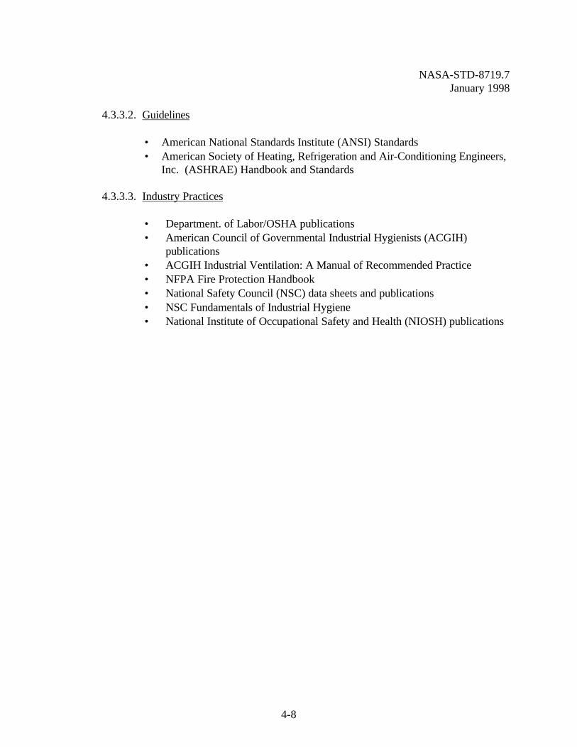
4.3.3.2. Guidelines
• American National Standards Institute (ANSI) Standards• American Society of Heating, Refrigeration and Air-Conditioning Engineers,
Inc. (ASHRAE) Handbook and Standards
4.3.3.3. Industry Practices
• Department. of Labor/OSHA publications• American Council of Governmental Industrial Hygienists (ACGIH)
publications• ACGIH Industrial Ventilation: A Manual of Recommended Practice• NFPA Fire Protection Handbook• National Safety Council (NSC) data sheets and publications• NSC Fundamentals of Industrial Hygiene• National Institute of Occupational Safety and Health (NIOSH) publications
NASA-STD-8719.7January 1998
5-1
CHAPTER 5FACILITY SYSTEM SAFETY PROCESS
5.1 INTRODUCTION
System safety engineering, as presented earlier in this document, is an approach used to identifydeficiencies in system or facility design/acquisition, facility modification, associated testing, andoperational sequences, which can result in an element of risk. System safety is used to assess riskby examining all elements and their interaction in the operating environment. A system safetyprogram ensures the integration of safety within the facility acquisition process. The objectives ofa facility system safety program are:
• To ensure that hazards inherent to the design, equipment, and intended use of thefacility are eliminated, or the resultant risk is controlled to an acceptable level;
• To maximize operational readiness and mission protection through mishap preventionmeasures by ensuring that appropriate hazard control measures are designed andconstructed into the facility in a timely manner and at minimum cost;
• To reduce safety and occupational health retrofit and modification requirements afterthe design stage;
• To ensure that safety and occupational health lessons-learned from previouslyconstructed similar facilities are incorporated in facility designs; and
• To ensure that modifications do not increase the risk level of a facility.
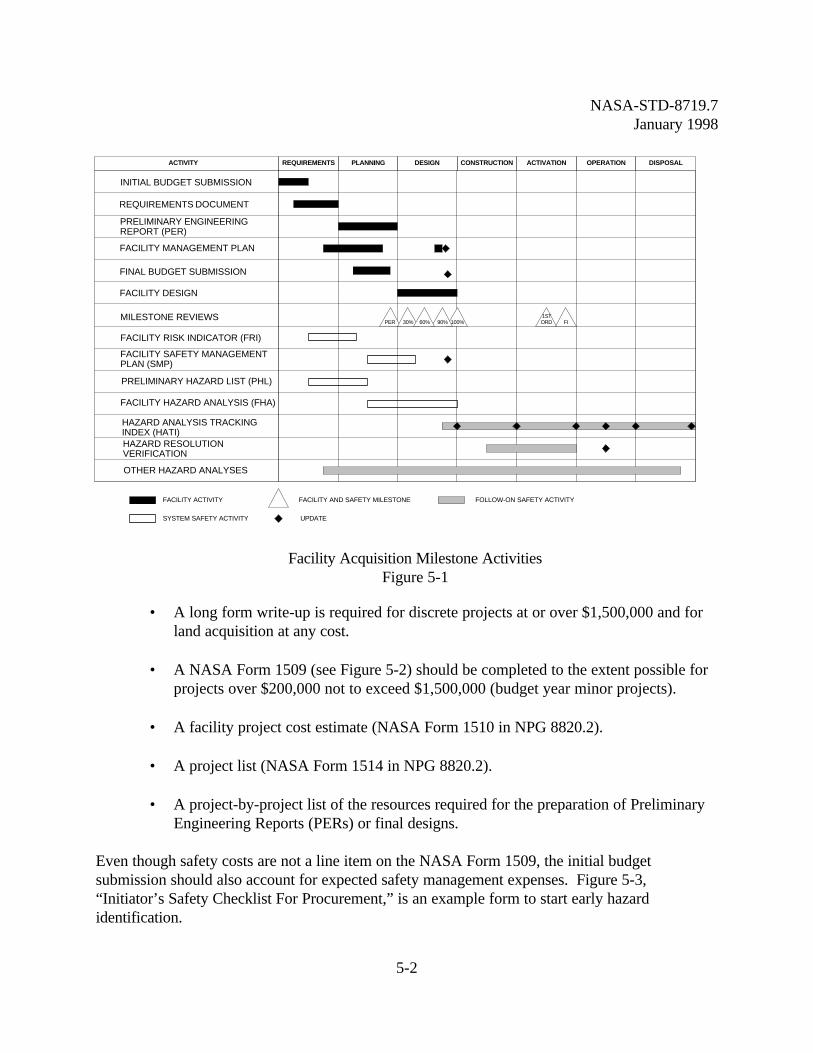
All facility acquisition schedules and descriptions of facility acquisition activities are taken fromNPG 8820.2, “Facility Project Implementation Handbook.” NASA has seven facility projectmodification or construction phases: requirements, planning, design, construction, activation,operation, and disposal. Facility system safety activities take place concurrent with the normalfacility acquisition process. These activities are shown in Figure 5-1.
The importance of the review process cannot be overemphasized; safety retrofit costs incurred inthe operations phase can be two to ten times the cost of changes incurred during the design phase.
5.2 REQUIREMENTS PHASE
5.2.1. Initial Budget Submission. The Center Director provides the initial budgetsubmission for the Construction of Facilities (CoF) project. This submission provides appropriatefacility planning and budget documentation depending on the type of project. The requireddocumentation is listed below.
NASA-STD-8719.7January 1998
5-2
• A long form write-up is required for discrete projects at or over $1,500,000 and forland acquisition at any cost.
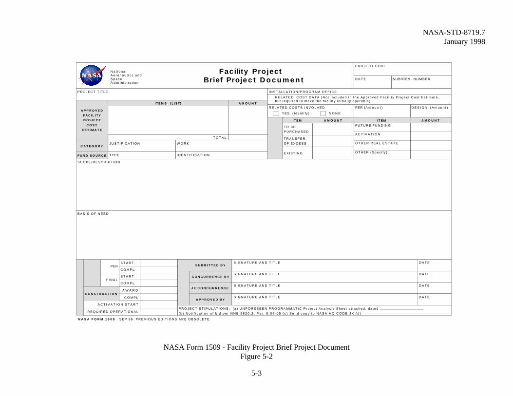
• A NASA Form 1509 (see Figure 5-2) should be completed to the extent possible forprojects over $200,000 not to exceed $1,500,000 (budget year minor projects).
• A facility project cost estimate (NASA Form 1510 in NPG 8820.2).
• A project list (NASA Form 1514 in NPG 8820.2).
• A project-by-project list of the resources required for the preparation of PreliminaryEngineering Reports (PERs) or final designs.
Even though safety costs are not a line item on the NASA Form 1509, the initial budgetsubmission should also account for expected safety management expenses. Figure 5-3,“Initiator’s Safety Checklist For Procurement,” is an example form to start early hazardidentification.
REQUIREMENTS PLANNING DESIGN CONSTRUCTION ACTIVATION OPERATION DISPOSAL
INITIAL BUDGET SUBMISSION
MILESTONE REVIEWS
PRELIMINARY ENGINEERINGREPORT (PER)
REQUIREMENTS DOCUMENT
FACILITY MANAGEMENT PLAN
FINAL BUDGET SUBMISSION
FACILITY DESIGN
FACILITY RISK INDICATOR (FRI)
FACILITY SAFETY MANAGEMENTPLAN (SMP)
PRELIMINARY HAZARD LIST (PHL)
FACILITY HAZARD ANALYSIS (FHA)
HAZARD ANALYSIS TRACKINGINDEX (HATI)HAZARD RESOLUTIONVERIFICATION
ACTIVITY
100%
OTHER HAZARD ANALYSES
FACILITY ACTIVITY
SYSTEM SAFETY ACTIVITY
FACILITY AND SAFETY MILESTONE
UPDATE
FOLLOW-ON SAFETY ACTIVITY
90%PER 30%1STORD60% FI
Facility Acquisition Milestone ActivitiesFigure 5-1
NASA-STD-8719.7January 1998
5-3
NASA Form 1509 - Facility Project Brief Project DocumentFigure 5-2
Facility Project Brief Proje c t D o c u m e n t
N A S A F O R M 1 5 0 9 S E P 9 6 P R E V I O U S E D I T I O N S A R E O B S O L E T E .
N a t i o n a lA e r o n a u t i c s a n dS p a c eA d m in i s t ra t i on
PROJECT T ITLE
P R O J E C T C O D E
D A T E
I N S T A L L A T I O N / P R O G R A M O F F I C E
S U B / R E V . N U M B E R
A P P R O V E D
F A C I L I T Y
P R O J E C T
C O S T
E S T I M A T E
S U B M I T T E D B YS I G N A T U R E A N D T I T L E D A T E
I T E M S ( L I S T ) A M O U N T
A M O U N T A M O U N T
C O N C U R R E N C E B Y
C A T E G O R YJ U S T I F I C A T I O N W O R K
F U N D S O U R C E TYPE I D E N T I F I C A T I O N
R E L A T E D C O S T D A T A ( N o t i n c l u d e d i n t h e A p p r o v e d F a c i l i t y P r o j e c t C o s t E s t i m a t e ,b u t r e q u i r e d t o m a k e t h e f a c i l i t y i n i t i a l l y o p e r a b l e )
R E L A T E D C O S T S I N V O L V E D PER (A m o u n t )
D E S I G N ( A m o u n t )
T O T A L
T O B E
P U R C H A S E D
T R A N S F E R
O F E X C E S S
E X I S T I N G
S I G N A T U R E A N D T I T L E D A T E
J X C O N C U R R E N C E S I G N A T U R E A N D T I T L E D A T E
A P P R O V E D B YS I G N A T U R E A N D T I T L E D A T E
S C O P E / D E S C R I P T I O N
B A S I S O F N E E D
PER
F I N A L
A C T I V A T I O N S T A R T
R E Q U I R E D O P E R A T I O N A L
C O N S T R U C T I O N
I T E M
F U T U R E F U N D I N G
A C T I V A T I O N
O T H E R R E A L E S T A T E
O T H E R ( S p e c i f y )
I T E M
Y E S ( I d e n t i f y ) N O N E
S T A R T
C O M P L
S T A R T
C O M P L
A W A R D
C O M P L
P R O J E C T S T I P U L A T I O N S : ( a ) U N F O R E S E E N P R O G R A M M A T I C P r o j e c t A n a l y s i s S h e e t a t t a c h e d , d a t e d
( b ) N o t i f i c a t i o n o f b i d p e r N H B 8 8 2 0 . 2 , P a r . 6 . 0 4 - 0 5 ( c ) S e n d c o p y t o N A S A H Q C O D E J X ( d )
NASA-STD-8719.7January 1998
5-4
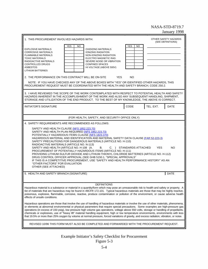
1. THIS PROCUREMENT INVOLVED HAZARDS WITH: OTHER SAFETY HAZARDS(SEE DEFINITIONS)
YES NO YES NOEXPLOSIVE MATERIALS OXIDIZING MATERIALSCORROSIVE MATERIALS IONIZING RADIATIONFLAMMABLE MATERIALS NON-IONIZING RADIATIONTOXIC MATERIALS ELECTRO MAGNETIC RAD.RADIOACTIVE MATERIALS SEVERE NOISE OR VIBRATIONCONTROLLED DRUGS CONFINED SPACESASBESTOS HI VOLTAGE (ABOVE 500V)LITHIUM BATTERIES
2. THE PERFORMANCE ON THIS CONTRACT WILL BE ON-SITE YES � NO�
NOTE: IF YOU HAVE CHECKED ANY OF THE ABOVE BOXES WITH “YES” OR IDENTIFIED OTHER HAZARDS, THISPROCUREMENT REQUEST MUST BE COORDINATED WITH THE HEALTH AND SAFETY BRANCH, CODE 250.2.
3. I HAVE REVIEWED THE SCOPE OF THE WORK CONTEMPLATED WITH RESPECT TO POTENTIAL HEALTH AND SAFETYHAZARDS INHERENT IN THE ACCOMPLISHMENT OF THE WORK AND ALSO ANY SUBSEQUENT HANDLING, SHIPMENT,STORAGE AND UTILIZATION OF THE END PRODUCT. TO THE BEST OF MY KNOWLEDGE, THE ABOVE IS CORRECT.
INITIATOR’S SIGNATURE CODE TEL. EXT. DATE
(FOR HEALTH, SAFETY, AND SECURITY OFFICE ONLY)
4. SAFETY REQUIREMENTS ARE RECOMMENDED AS FOLLOWS:
� SAFETY AND HEALTH CLAUSE (NFS 1852.223.70)� SAFETY AND HEALTH PLAN REQUIRED (NFS 1852.223.73)� POTENTIALLY HAZARDOUS ITEMS CLAUSE (NFS 1823.370)� HAZARDOUS MATERIAL AND IDENTIFICATION AND MATERIAL SAFETY DATA CLAUSE (FAR 52-223-3)� SAFETY PRECAUTIONS FOR DANGEROUS MATERIALS (ARTICLE NO. H-110)� RADIOACTIVE MATERIALS (ARTICLE NO. N-113)� SAFETY AND HEALTH (ARTICLE NO. H-108 (A. � B. � C. �) STANDARDS ATTACHED YES � NO �� PROCUREMENT OF POTENTIALLY HAZARDOUS ITEMS (ARTICLE NO. H-111)� PROVIDING LITHIUM-SULFUR DIOXIDE AND LITHIUM-THIONYL CHLORIDE BATTERIES (ARTICLE NO. H-112)� DRUG CONTROL OFFICER APPROVAL (SEE GHB 5150.1, “SPECIAL APPROVALS”� IF THIS IS A COMPETITIVE PROCUREMENT, USE “SAFETY AND HEALTH PERFORMANCE HISTORY” AS AN “OTHER FACTORS” FOR EVALUATION� OTHER (SEE ATTACHED)
5. HEALTH AND SAFETY BRANCH (SIGNATURE) DATE
DEFINITIONSHazardous material is a substance or material in a quantity/form which may pose an unreasonable risk to health and safety or property. Alist of materials that are hazardous may be found in 49CFR 172.101. Typical hazardous materials are those that may be highly reactive,poisonous, explosive, flammable, corrosive, reactive, produce contamination or pollution of the environment, or cause adverse healtheffects of unsafe conditions.
Hazardous operations are those that involve the use of handling of hazardous materials or involve the use of other materials, phenomena,or elements at abnormal environmental or physical parameters that require special precautions. Some examples are high-pressure gasoperations (in excess of 150 psig), low pressure high volume gas operations, voltage above 550 volts, storage or handling of propellants,chemicals or explosives, use of “heavy lift” material handling equipment, high or low temperature environments, environments with lessthat 19.5% or more than 25% oxygen by volume at normal pressure, forced variations of gravity, and excess radiation, vibration, or noise.
REVISED 10/96 THIS FORM MUST ALSO BE COMPLETED AND FORWARDED WITH THE PROCUREMENT REQUEST.
Example Initiator’s Safety Checklist for ProcurementFigure 5-3
NASA-STD-8719.7January 1998
5-5
5.2.2. Environmental Projects and Studies. Coordinate all environmental projects andstudies with the NASA Safety and Environmental Offices at the Centers. The NASA Safety andEnvironmental Offices will provide guidance on the documents required for submittingenvironmental projects.
5.2.3. Requirements Document. The requirements document is essentially an update andexpansion of a facility concept study (the initial preparatory work on a facility) with a majoremphasis on the project description. The requirements document incorporates the results of anypreliminary engineering reports or studies that have been completed and provides detailed criteria(e.g., size, location, environmental requirements, etc.) for each of the rooms, activities, orfunctions included in the facility. The requirements document will include elements such as:
• A narrative description of the purpose and/or function of the facility;
• The physical dimensions of the area including ceiling or hook height;
• The number and type of personnel assigned to the area;
• Environmental requirements;
• Process power, grounding, and lighting requirements;
• Fire protection requirements;
• Communication system requirements;
• Special structural requirements;
• Security requirements;
• Material handling requirements;
• A listing of major items of process equipment to be installed;
• Environmental pollution control requirements; and
• The identification of the present location of the activity.
• The requirements document is the primary input to the Preliminary EngineeringReport.
5.2.4. Facility Management Plan. The facility project management plan establishes theschedule for implementation of a facility project and assigns responsibility and authority forvarious actions. The plan also provides a detailed outline of the steps in the facilityimplementation process, with provisions for well defined milestones to measure progress. Itserves as the principal tool for determining work progress and establishes priorities for allocationof resources to ensure that the project is completed on time. During implementation of the facilityproject, the plan is updated, expanded, and used to maintain the overall project status during thebudget process and the design, construction, and operation phases. NASA Headquarters mustapprove the project management plan for projects having a total cost of $5,000,000 or greater. The plan includes:
NASA-STD-8719.7January 1998
5-6
• Identification of individuals or organizations responsible for project implementation;
• A description of the functional requirement including the operational need date, and,if required, the schedule for joint or beneficial occupancy dates (see NPG 8820.2);
• A description of the planned facility including capacity, scope, location, specialfeatures, and current cost estimates;
• An identification of all environmental requirements;
• The development of an acquisition plan ensuring that the funding method supports theoperational need date(s); and
• Network or bar-type charts depicting a time-phased schedule with intermediatemilestones.
The facility project management plan is not required for projects less than $5,000,000, but isrecommended and should contain adequate details based on project complexities.
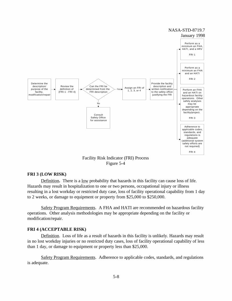
5.2.5. Facility Risk Indicator (FRI)
5.2.5.1. Purpose of FRI . The FRI is a first step to estimating the combined level of riskassociated with a facility. The FRI assessment classifies the severity of potential hazards inherentto the facility itself: its operations, processes, environment, equipment, potential interfaces, andpersonnel. Although the FRI can be performed at any time during the Facility Life Cycle, the FRIis generally performed early in the acquisition program during the conceptual phase to ensurepotential hazards are identified. The FRI is the initial safety assessment used to help determinethe level of system safety effort required to meet NASA safety requirements. This process beginsby identifying hazards that may exist at any given point throughout the life of the facility. TheFRI evaluation alerts the Facility Project Manager and other acquisition managers of the potentialsafety concerns within a facility.
The extent to which system safety analysis is applied to facility acquisition is initially based uponthe FRI assessment. The FRI is categorized into four risk indicators ranging from a FRI of 1(High Risk) to a FRI of 4 (Minimal Risk). A FRI of 1 signifies major risk associated withpersonnel safety, operational productivity, design effectiveness, environmental impact, and/orother user interfaces. A FRI of 4 indicates negligible or low risk. The potential hazards inherentto the facility are evaluated using the following criteria as evaluation factors:
• Life Safety - hazards which could potentially cause death or serious injury topersonnel;
• Mission Continuity - failures which could have serious impact on mission capabilityand/or operability;
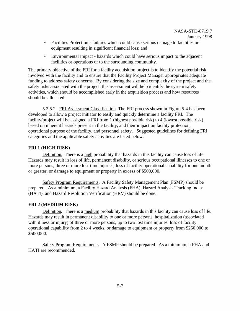
NASA-STD-8719.7January 1998
5-7
• Facilities Protection - failures which could cause serious damage to facilities orequipment resulting in significant financial loss; and
• Environmental Impact - hazards which could have serious impact to the adjacentfacilities or operations or to the surrounding community.
The primary objective of the FRI for a facility acquisition project is to identify the potential riskinvolved with the facility and to ensure that the Facility Project Manager appropriates adequatefunding to address safety concerns. By considering the size and complexity of the project and thesafety risks associated with the project, this assessment will help identify the system safetyactivities, which should be accomplished early in the acquisition process and how resourcesshould be allocated.
5.2.5.2. FRI Assessment Classification. The FRI process shown in Figure 5-4 has beendeveloped to allow a project initiator to easily and quickly determine a facility FRI. Thefacility/project will be assigned a FRI from 1 (highest possible risk) to 4 (lowest possible risk),based on inherent hazards present in the facility, and their impact on facility protection,operational purpose of the facility, and personnel safety. Suggested guidelines for defining FRIcategories and the applicable safety activities are listed below.
FRI 1 (HIGH RISK)Definition. There is a high probability that hazards in this facility can cause loss of life.
Hazards may result in loss of life, permanent disability, or serious occupational illnesses to one ormore persons, three or more lost-time injuries, loss of facility operational capability for one monthor greater, or damage to equipment or property in excess of $500,000.
Safety Program Requirements. A Facility Safety Management Plan (FSMP) should beprepared. As a minimum, a Facility Hazard Analysis (FHA), Hazard Analysis Tracking Index(HATI), and Hazard Resolution Verification (HRV) should be done.
FRI 2 (MEDIUM RISK)Definition. There is a medium probability that hazards in this facility can cause loss of life.
Hazards may result in permanent disability to one or more persons, hospitalization (associatedwith illness or injury) of three or more persons, up to two lost time injuries, loss of facilityoperational capability from 2 to 4 weeks, or damage to equipment or property from $250,000 to$500,000.
Safety Program Requirements. A FSMP should be prepared. As a minimum, a FHA and HATI are recommended.
NASA-STD-8719.7January 1998
5-8
FRI 3 (LOW RISK)Definition. There is a low probability that hazards in this facility can cause loss of life.
Hazards may result in hospitalization to one or two persons, occupational injury or illnessresulting in a lost workday or restricted duty case, loss of facility operational capability from 1 dayto 2 weeks, or damage to equipment or property from $25,000 to $250,000.
Safety Program Requirements. A FHA and HATI are recommended on hazardous facilityoperations. Other analysis methodologies may be appropriate depending on the facility ormodification/repair.
FRI 4 (ACCEPTABLE RISK)Definition. Loss of life as a result of hazards in this facility is unlikely. Hazards may result
in no lost workday injuries or no restricted duty cases, loss of facility operational capability of lessthan 1 day, or damage to equipment or property less than $25,000.
Safety Program Requirements. Adherence to applicable codes, standards, and regulationsis adequate.
Determine thedescription/
purpose of thefacility,
modification/repair
Review thedefinition of
(FRI-1 - FRI 4)
ConsultSafety Officefor assistance
Assign an FRI of1, 2, 3, or 4
Provide the facilitydescription and
written notificationto the safety officejustifying the FRI
Perform as aminimum an FHA,HATI, and a HRV
FRI 1
Perform as aminimum an FHA
and an HATI
FRI 2
Perform an FHAand an HATI on
hazardous facilityoperations. Other
safety analysesmay be
appropriatedepending on thefacility/project.
FRI 3
Adherence toapplicable codes,
standards, andregulations is
adequate(additional systemsafety efforts are
not required)
FRI 4
Can the FRI bedetermined from the
FRI description
No
Yes
Facility Risk Indicator (FRI) ProcessFigure 5-4
NASA-STD-8719.7January 1998
5-9
The FRI process (Figure 5-4) begins with a review of the proposed facility or project description.Often the FRI can be determined based on comparing the information presented in the facilitydescription to the FRI categories presented in the previous paragraphs. However, some facilitydescriptions are not adequate to determine the FRI and additional research is required todetermine the classification of the facility or project. A review of a checklist, such as the “TypicalEnergy Sources Checklist” provided in Appendix A, can assist in determining the FRI for thefacility or project, particularly if the Center Safety Department helps with the evaluation.
A Facility Risk Indicator summarizes potential hazards inherent to a facility and its operation. This technique is used to rank hazardous aspects of a specific facility and enables a determinationof appropriate safety activities required to minimize potential hazards associated with the facilityand its operation.
5.2.6. Preliminary Hazard List. The purpose of the Preliminary Hazard List (PHL) is toidentify and list hazards or areas of concern likely to be present in the facility including theenvironment in which the facility will be located. The PHL is the baseline document for thefacility system safety effort. The following identification methods are typically used to identify thehazards associated with energy sources, hazardous operations, or procedures, and potentialaccidents that may result in injury to personnel or damage to the facility.
• Surveying the site;• Interviewing site personnel;• Drawing on expertise in the subject area;• Reviewing lessons learned;• Analyzing similar facilities;• Analyzing available technical data;• Reviewing energy sources;• Reviewing requirements documents; and• Reviewing the Project Management Plan.
Alone, any of these methods will identify some hazards, but a logical completion of all or acombination of these steps will result in the development of a more thorough PHL. Once thePHL is completed it is used to help determine what hazards exist in a facility. The PHL alsoprovides input for the Facility Hazard Analysis (FHA). The PHL can be prepared in any logicalformat that allows the free flow of ideas. An example of a completed PHL is provided inAppendix B. This list was derived from reviewing energy sources, equipment, operations,procedures, personnel interviews, and an experts panel. Each of the above listed hazardidentification methodologies is described in the following paragraphs.
5.2.6.1. Research of Similar Facilities. New facilities often are built to house someexisting operations, usually at or near the proposed site. If the entire operation is new, thensimilar or related operations and systems usually can be identified at other NASA Centers.
NASA-STD-8719.7January 1998
5-10
Existing facilities, proposed operations, and the proposed site should be reviewed looking forindications of potential hazards that could exist in the proposed facility. This is the mostimportant step, as it provides first-hand invaluable information to the actual facility andoperations.
5.2.6.2. Interviews With User Personnel. Interviews with personnel actually involvedwith the day-to-day operations of the new system or facility can often provide information thatdoes not appear in planning or technical documentation. Operations personnel are often eager toprovide input into the overall design process for the new system or facility since they willeventually be using the facility. For instance, an interview may determine that inadequate lightinghas been a problem for workers. Potential hazards resulting from poor lighting should then bedocumented in the PHL and subsequently addressed in the Facility Hazard Analysis.
5.2.6.3. Experts Panel Meeting. One of the most successful methods to identify hazardsrelated to a project can be accomplished by conducting an "Experts Panel" meeting. This meetingbrings together project engineers, representatives from cognizant safety organizations, and userswho know the system or facility under design, and personnel with expertise in some aspect of thesystem or facility. During a brainstorming session, the experts analyze the system and, based ontheir area of expertise, identify potential hazards for the new system or facility.
To prepare for a typical Experts Panel meeting, a system description and initial draft of the PHLshould be developed. The draft PHL will serve as the outline for discussion during the meeting. The experts are provided with the system description and draft PHL prior to the meeting toprepare. Choice of the "experts" attending the meeting vary greatly depending on the type offacility or system and the personnel available; the expertise many times comes from surprisingareas. For example, a former design engineer for a chemical processing plant with experience inflammable liquid/gas transferring operations may provide considerable valuable input into a PHLbeing conducted on the design of a fueling facility for a spacecraft propulsion system. Anotherengineer with several years of experience as an OSHA inspector may provide insight during theExperts Panel meeting for the development of a PHL for a machine shop.
The Experts Panel meeting provides the opportunity for an organized review of all subsystemswithin the system or facility. As a result, the PHL develops into a refined and morecomprehensive PHL. Although use of additional hazard identification methods discussed in thissection ensure a more thorough hazard identification process, the PHL produced as a result of theExperts Panel Meeting typically provides a very realistic list of the most significant hazards to beincluded.
5.2.6.4. Lessons Learned. Mishap data from the Lessons Learned Information System(LLIS) can be used to evaluate facts associated with mishap events that could have impact orprovide information on controlling or mitigating hazards in like facilities. The primary,contributing and potential cause; and recommend corrective actions to prevent recurrence ofspecific and similar mishaps may be available in the LLIS.
NASA-STD-8719.7January 1998
5-11
5.2.6.5. Similar Facilities. Analyzing similar facilities is another method for gatheringhazard information. For instance, a hazard analysis for a spacecraft integration facility mayprovide valuable data as a starting point for an aircraft integration facility PHL encompassingsimilar operations. It is important to note that hazards identified from previously developedhazard analyses require careful review to ensure applicability.
5.2.6.6. Technical Data. Codes, standards, and regulations provide useful information inidentifying facility hazards. Documents may include: NASA Policy Directives (NPDs), NASAProcedures and Guidellines (NPGs), NASA Technical Standards (NTSs), American NationalStandards Institute (ANSI) standards, NFPA standards, American Society for Testing andMaterials (ASTM) standards, OSHA regulations; and Environmental Protection Agency (EPA)regulations. There may also be recommended practices and guidelines from professionalorganizations that deal with specific items used in the facility.
5.2.6.7. Review of Energy Sources. A useful systematic approach to conducting anengineering review of a system or facility may include checklist-based analysis, such as the EnergyTrace Barrier Analysis (ETBA) (see Paragraph 7.2 for more information). This methodologyproposes that hazards in a system or facility will be caused by an inadvertent release of energystored in the system, facility, or environment. Thus, if all sources of energy can be identified, thentheoretically all potential hazards can be identified. After developing an understanding of thesystem or facility under study, checklists are reviewed for applicable potential hazard sources. This and other checklist methodologies provide further confidence that a thorough PHL is beingdeveloped (see Appendix A for a “Typical Energy Sources Checklist”).
5.2.6.8. Summary. The Preliminary Hazard List is conducted early in the system safetyanalysis phase. Usually an ETBA is conducted on the system to develop the list. The PHL is aninitial hazard identification effort. It is the basis for the follow-on, in-depth safety analysis. Theinformation generated from the PHL helps evaluate the initial design requirements, provide datafor concept and trade-off studies, and provide information on specific safety concerns. (seeAppendix B for a “Preliminary Hazard List Example - General Laboratory Facility”)
5.3 PLANNING PHASE
5.3.1 Preliminary Engineering Report. The Preliminary Engineering Report (PER) is alink between the pre-planning phase and the final design phase of a facility. The PER establishes aproject cost by providing an engineering cost basis. The PER includes preliminary engineeringstudies, the analysis of alternatives, essential design requirements and criteria, schematic single-line drawings, sitting information, outline specifications, and cost estimates. A preliminaryengineering report provides:
• A basic source of necessary data and cost estimates regarding the facility workrequired to support budgetary or other proposals;
NASA-STD-8719.7January 1998
5-12
• A functional need and serves as a mechanism for its subsequent consideration;
• A comprehensive justification for the proposed facility;
• Early and timely development of the facility project or work package(s) to meetfunctional needs including analysis of alternatives;
• Criteria for preparation of final architectural engineering design drawings andspecifications for an individual facility project and defines the work for theconstruction phase(s); and
• The design and construction steps to be followed such as work packages,construction management, schedules, and interior milestones for the execution of theproject.
5.3.2 Final Budget Submission. The field installations make final budget submissionsthat pro the following budget year facility project information:
• An updated long form write-up for Headquarters supported discrete projects,including updated material that responds to questions raised by the seniormanagement review;
• An updated NASA Form 1509;• An updated facility project cost estimate, NASA Form 1510;• An updated priority list, NASA Form 1514, in the same format as the initial
submission and signed by the Center Director or designated representative; and• PERs for discrete projects if required.
5.3.3. Facility Safety Management Plan. The Facility Safety Management Plan (FSMP)should be written to meet the requirements of NHB 1700.1 (V1-B), Chapter 8. According toNHB 1700.1 (V1-B) Paragraph 807:
“Field Installations shall document and maintain a written Facility SafetyManagement Plan (FSMP) for each major facility acquisition. This plan shallbe used to implement tailored safety requirements, including organizationalresponsibilities, resources, milestones, methods of accomplishment, depth ofeffort, and integration with other program engineering and managementactivities and related systems.”
The plan should clearly indicate how acquisition of the specific facility or facility modificationmeets the requirements of the overall System Safety Program Plan for the Center. The FSMPshould be started after completion of the PHL and should be complete at the 30% Design Phase. The basic objective is to document recommended safety efforts for the remainder of the life cycleof the facility.
NASA-STD-8719.7January 1998
5-13
The FSMP should document the facility hazard resolution process and define when hazards haveeither been closed, accepted, or eliminated. For example, the plan can state that if hazards appearclosed on 90% design drawings, then the hazards are closed. Another plan might state thathazards will not be closed until they are actually inspected in the field (this method isadvantageous for facilities with a FRI of 1). The plan will also define and establish themanagement authority for closing or accepting hazards.
A Hazard Analysis Sub-Committee (HASC) may be established by the plan to review all hazardsand make recommendations to management. The HASC usually consists of representatives fromthe safety office, the user’s group, the architecture and engineering firm, and the facility projectmanager.
For a FRI 1 or 2 facility acquisition project, the FSMP may include requirements for additionalhazard analyses such as a Sub-System Hazard Analysis, or an Operating and Support HazardAnalysis; requirements for a Hazard Analysis Tracking Index; and requirements for incorporationof special testing requirements to assure that the proposed facility can operate safely. A sampleTable of Contents for a FSMP for a FRI 1 Facility is provided as Appendix C.
The FSMP should provide a method to ensure that:
• A safe design is being implemented in a timely, cost-effective manner;
• Hazards associated with the facility, identified during the FHA, are tracked (using aHazard Analysis Tracking Index) to ensure they are evaluated and eliminated orcontrolled to an acceptable level throughout the life cycle;
• Minimum risk is involved in the design, materials, testing, and operation of thefacility;
• Changes to the design, made during construction or installation/testing, do not impactsafety;
• Training is provided for personnel involved in hazardous operations and processes;
• Codes, standards, and regulations are met;
• Safety milestones meet facility program requirements;
• Safety in operation and maintenance is demonstrated and proved; and
• Safety in disposal of the facility is established with clear procedures and methods forfacility disposal.
In summary, the FSMP should ensure that a tailored program is developed for the particularfacility acquisition.
NASA-STD-8719.7January 1998
5-14
5.3.4. Facility Hazard Analysis (FHA)
5.3.4.1. Purpose of a FHA. The FHA is a preliminary hazard analysis performed duringthe planning and decision phases of an acquisition program. For NASA facilities, the FHA is theinitial, and often the only, risk evaluation of a facility or facility modification. The analysisincludes a preliminary assessment of the facility's systems and subsystems, operations, processes,equipment, building structure, personnel, environment, and materials. The FHA is built uponprevious studies or assessments performed, i.e., FRI and PHL; however, this analysis is moredetailed. When complete, the FHA is used to establish a Hazard Analysis Tracking Index and toupdate the FSMP that will identify additional analyses required, if necessary, during subsequentphases. This documentation provides useful safety input for the decision making process used intrade studies, design criteria, and operational goals.
The FHA is prepared to identify, evaluate, and make recommendations for the elimination,control, or acceptance of hazards that could potentially cause:
• Loss of life and/or serious injury to personnel;
• Serious damage to facilities and/or equipment resulting in large dollar loss;
• Failures with serious adverse impact on mission capability, mission operability, orpublic opinion; or
• Detrimental harm to the environment and the surrounding community.
When the system safety effort is part of the overall design effort, the system safety engineers canparticipate in design review meetings and often consult with the designers throughout the FHAdevelopment. This arrangement provides the system safety engineer with a better understandingof all of the design considerations and how safety may play a part. Similarly, close contact withthe system safety engineers provides the designers with a better idea of the major safety concernsbeing identified throughout the system safety analysis process. When the system safety effort isconducted independently from the design and the system safety engineer does not have access tothe design engineers, then the analysis is usually less comprehensive and often results inunappreciated "surprises" for the facility designers.
5.3.4.2. Scope of an FHA.. The FHA places the greatest emphasis onelimination/control of hazards early in the life cycle. The FHA is reviewed and revised severaltimes to reflect the status of safety-related hazards that exist throughout the design cycle, i.e.,during the 30%, 60%, 90%, and 100% design reviews; the completion of building construction;the end of system/subsystem installation; and prior to facility operations. Obviously, only alimited amount of information is available during the 30% design review. However, significantlymore information is available during the 60% design review and should be reflected in the revisedFHA.
NASA-STD-8719.7January 1998
5-15
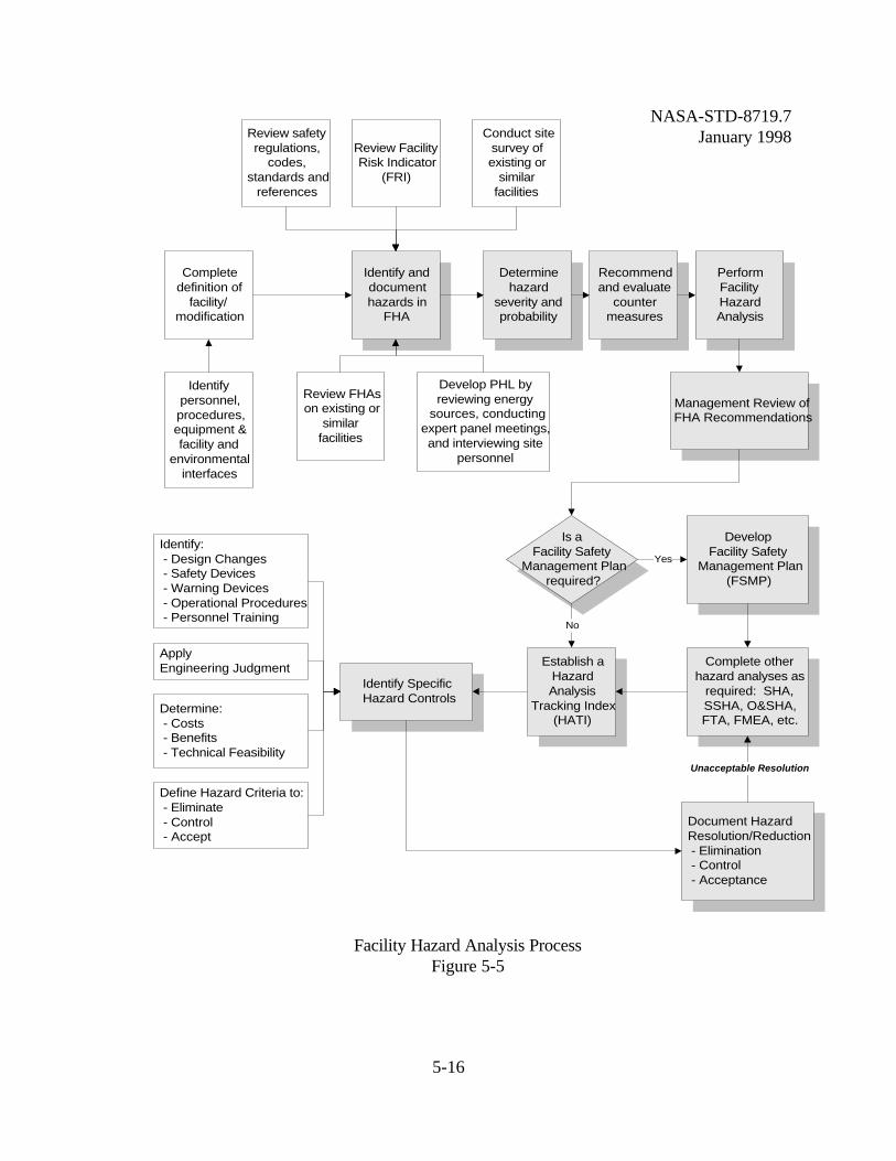
Each revision consists of reviewing the identified hazards and modifying the status of thosehazards that are either eliminated, controlled, accepted, or remain open for future consideration. It is essential to address each hazard as the design matures and to quickly report the status tomanagement so that additional hazard analyses or design modifications can be performed beforeprocurement and construction begin on the facility. This alleviates redesign efforts, maintainsmilestone objectives, and avoids unnecessary costs that could delay the completion and activationof the facility. The boundary of the FHA includes identification of hazards within the proposedfacility, hazards external to the facility with respect to its physical location, and hazards related tothe interface of the facility with the surrounding facilities and systems (i.e., fire protection watersupply, electrical utility systems, transportation, and safe separation including explosives,hazardous materials, security, etc.). The FHA may also address environmental issues outside ofthe facility. Coordination between the Safety and the Environmental Offices at each NASAInstallation establishes good practical judgment in examining environmental issues related to thefacility.
5.3.4.3. Development of a FHA. The Facility Hazard Analysis process is shown inFigure 5-5. The initial step in the Facility Hazard Analysis uses various information to determinethe hazards and level of risk associated with the facility and its operational use. The FHA is basedon the best available data, including mishap and lessons-learned information. It is developed by:
• Reviewing design drawings, PER, requirements document, plans, etc..
• Reviewing applicable safety regulations, codes, and standards.
• Reviewing the Facility Risk Index and Preliminary Hazard List.
• Reviewing/conducting site surveys and interviews with proposed users.
• Reviewing historical data or lessons learned from existing or similar facilities.
• Identifying personnel, procedures, equipment, and facility interfaces.
NASA-STD-8719.7January 1998
5-16
Review safetyregulations,
codes,standards and
references
Review FacilityRisk Indicator
(FRI)
Conduct sitesurvey ofexisting or
similarfacilities
Identify anddocumenthazards in
FHA
Completedefinition of
facility/modification
Identifypersonnel,procedures,equipment &facility and
environmentalinterfaces
Determinehazard
severity andprobability
Recommendand evaluate
countermeasures
PerformFacilityHazardAnalysis
Review FHAson existing or
similarfacilities
Develop PHL byreviewing energy
sources, conductingexpert panel meetings,and interviewing site
personnel
Management Review ofFHA Recommendations
Is aFacility Safety
Management Planrequired?
DevelopFacility Safety
Management Plan(FSMP)
Complete otherhazard analyses as
required: SHA,SSHA, O&SHA,FTA, FMEA, etc.
Establish aHazardAnalysis
Tracking Index(HATI)
Yes
No
Identify: - Design Changes - Safety Devices - Warning Devices - Operational Procedures - Personnel Training
Apply Engineering Judgment
Determine: - Costs - Benefits - Technical Feasibility
Document Hazard Resolution/Reduction - Elimination - Control - Acceptance
Identify SpecificHazard Controls
Define Hazard Criteria to: - Eliminate - Control - Accept
Unacceptable Resolution
Facility Hazard Analysis ProcessFigure 5-5
NASA-STD-8719.7January 1998
5-17
Each hazard identified is documented in the FHA. The format should allow for the inclusion ofthe results of additional safety analyses (if needed), and the monitoring of the status of eachhazard as the project proceeds from phase to phase.
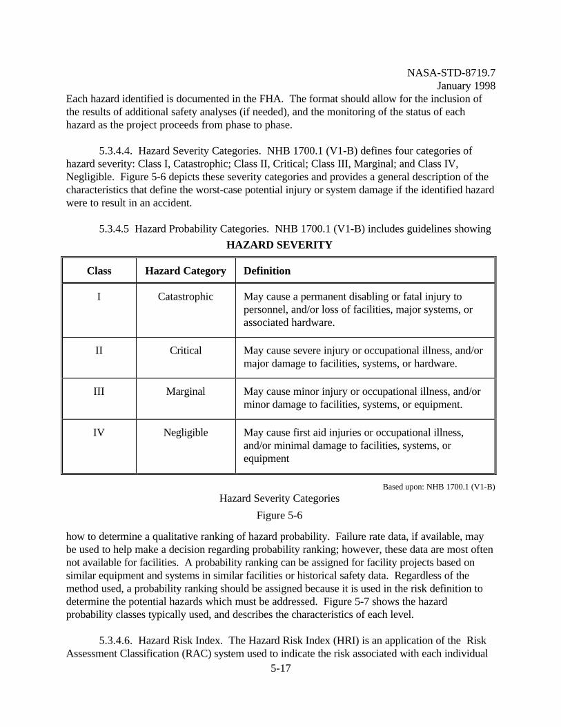
5.3.4.4. Hazard Severity Categories. NHB 1700.1 (V1-B) defines four categories ofhazard severity: Class I, Catastrophic; Class II, Critical; Class III, Marginal; and Class IV,Negligible. Figure 5-6 depicts these severity categories and provides a general description of thecharacteristics that define the worst-case potential injury or system damage if the identified hazardwere to result in an accident.
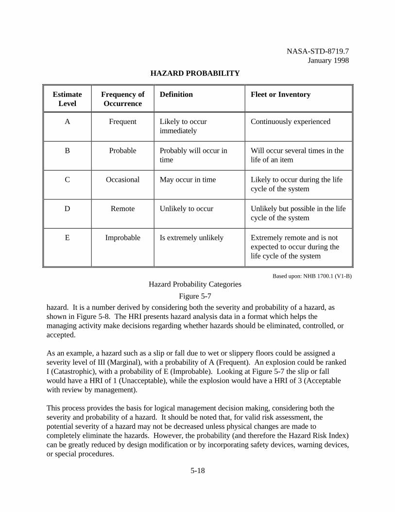
5.3.4.5 Hazard Probability Categories. NHB 1700.1 (V1-B) includes guidelines showing
how to determine a qualitative ranking of hazard probability. Failure rate data, if available, maybe used to help make a decision regarding probability ranking; however, these data are most oftennot available for facilities. A probability ranking can be assigned for facility projects based onsimilar equipment and systems in similar facilities or historical safety data. Regardless of themethod used, a probability ranking should be assigned because it is used in the risk definition todetermine the potential hazards which must be addressed. Figure 5-7 shows the hazardprobability classes typically used, and describes the characteristics of each level.
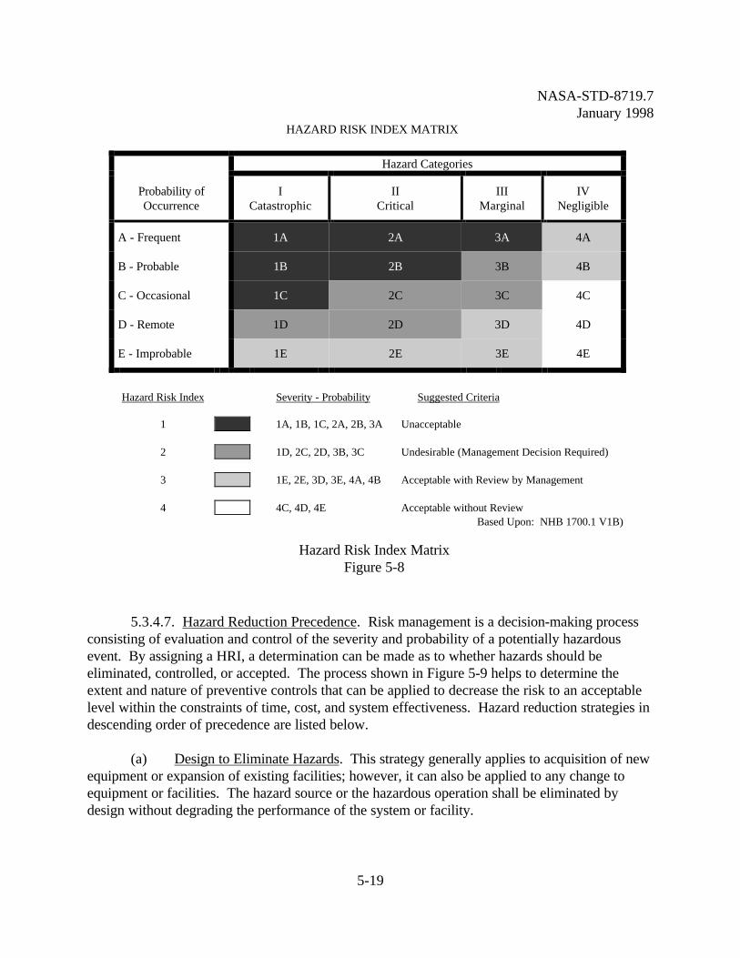
5.3.4.6. Hazard Risk Index. The Hazard Risk Index (HRI) is an application of the RiskAssessment Classification (RAC) system used to indicate the risk associated with each individual
HAZARD SEVERITY
Class Hazard Category Definition
I Catastrophic May cause a permanent disabling or fatal injury topersonnel, and/or loss of facilities, major systems, orassociated hardware.
II Critical May cause severe injury or occupational illness, and/ormajor damage to facilities, systems, or hardware.
III Marginal May cause minor injury or occupational illness, and/orminor damage to facilities, systems, or equipment.
IV Negligible May cause first aid injuries or occupational illness,and/or minimal damage to facilities, systems, orequipment
Based upon: NHB 1700.1 (V1-B)
Hazard Severity Categories
Figure 5-6
NASA-STD-8719.7January 1998
5-18
hazard. It is a number derived by considering both the severity and probability of a hazard, asshown in Figure 5-8. The HRI presents hazard analysis data in a format which helps themanaging activity make decisions regarding whether hazards should be eliminated, controlled, oraccepted.
As an example, a hazard such as a slip or fall due to wet or slippery floors could be assigned aseverity level of III (Marginal), with a probability of A (Frequent). An explosion could be rankedI (Catastrophic), with a probability of E (Improbable). Looking at Figure 5-7 the slip or fallwould have a HRI of 1 (Unacceptable), while the explosion would have a HRI of 3 (Acceptablewith review by management).
This process provides the basis for logical management decision making, considering both theseverity and probability of a hazard. It should be noted that, for valid risk assessment, thepotential severity of a hazard may not be decreased unless physical changes are made tocompletely eliminate the hazards. However, the probability (and therefore the Hazard Risk Index)can be greatly reduced by design modification or by incorporating safety devices, warning devices,or special procedures.
HAZARD PROBABILITY
EstimateLevel
Frequency ofOccurrence
Definition Fleet or Inventory
A Frequent Likely to occurimmediately
Continuously experienced
B Probable Probably will occur intime
Will occur several times in thelife of an item
C Occasional May occur in time Likely to occur during the lifecycle of the system
D Remote Unlikely to occur Unlikely but possible in the lifecycle of the system
E Improbable Is extremely unlikely Extremely remote and is notexpected to occur during thelife cycle of the system
Based upon: NHB 1700.1 (V1-B)
Hazard Probability Categories
Figure 5-7
NASA-STD-8719.7January 1998
5-19
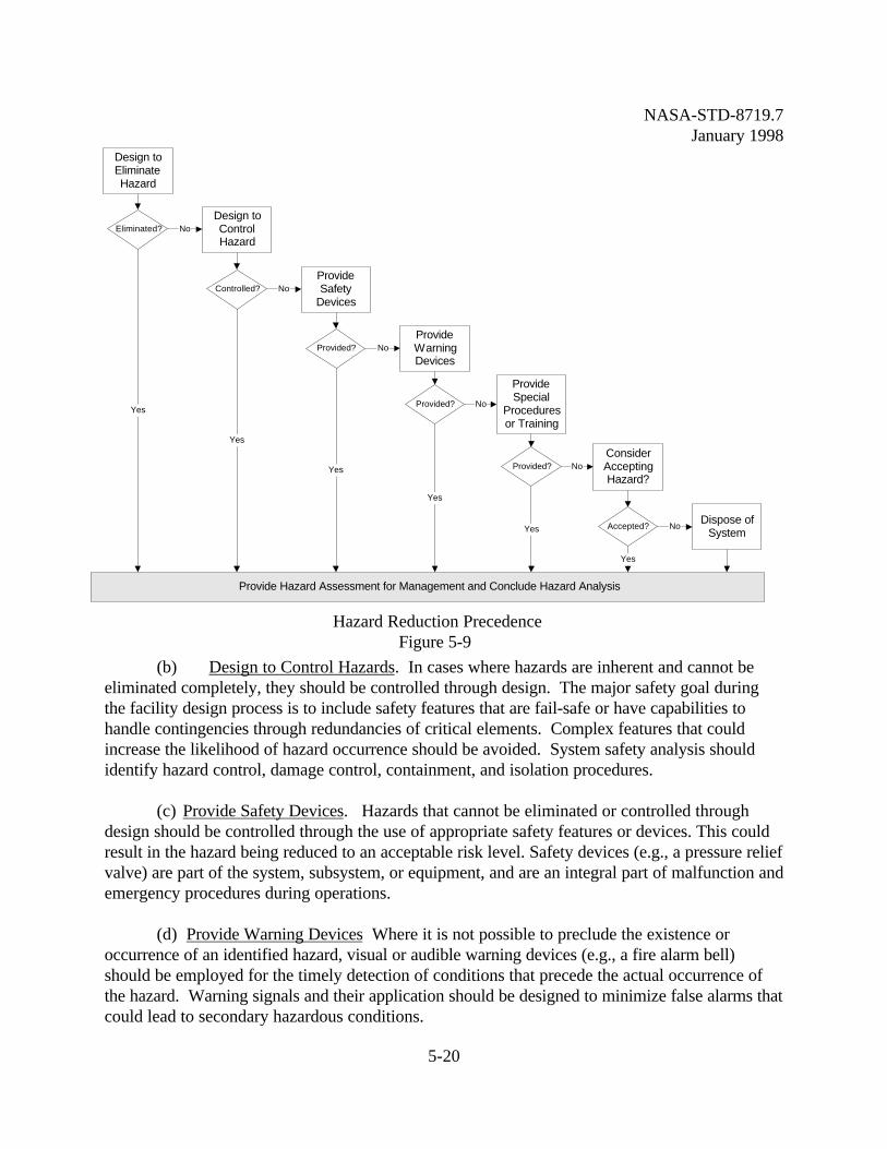
5.3.4.7. Hazard Reduction Precedence. Risk management is a decision-making processconsisting of evaluation and control of the severity and probability of a potentially hazardousevent. By assigning a HRI, a determination can be made as to whether hazards should beeliminated, controlled, or accepted. The process shown in Figure 5-9 helps to determine theextent and nature of preventive controls that can be applied to decrease the risk to an acceptablelevel within the constraints of time, cost, and system effectiveness. Hazard reduction strategies indescending order of precedence are listed below.
(a) Design to Eliminate Hazards. This strategy generally applies to acquisition of newequipment or expansion of existing facilities; however, it can also be applied to any change toequipment or facilities. The hazard source or the hazardous operation shall be eliminated bydesign without degrading the performance of the system or facility.
HAZARD RISK INDEX MATRIX
Hazard Categories
Probability ofOccurrence
ICatastrophic
IICritical
IIIMarginal
IVNegligible
A - Frequent 1A 2A 3A 4A
B - Probable 1B 2B 3B 4B
C - Occasional 1C 2C 3C 4C
D - Remote 1D 2D 3D 4D
E - Improbable 1E 2E 3E 4E
Hazard Risk Index Severity - Probability Suggested Criteria
1 1A, 1B, 1C, 2A, 2B, 3A Unacceptable
2 1D, 2C, 2D, 3B, 3C Undesirable (Management Decision Required)
3 1E, 2E, 3D, 3E, 4A, 4B Acceptable with Review by Management
4 4C, 4D, 4E Acceptable without ReviewBased Upon: NHB 1700.1 V1B)
Hazard Risk Index MatrixFigure 5-8
NASA-STD-8719.7January 1998
5-20
(b) Design to Control Hazards. In cases where hazards are inherent and cannot beeliminated completely, they should be controlled through design. The major safety goal duringthe facility design process is to include safety features that are fail-safe or have capabilities tohandle contingencies through redundancies of critical elements. Complex features that couldincrease the likelihood of hazard occurrence should be avoided. System safety analysis shouldidentify hazard control, damage control, containment, and isolation procedures.
(c) Provide Safety Devices. Hazards that cannot be eliminated or controlled throughdesign should be controlled through the use of appropriate safety features or devices. This couldresult in the hazard being reduced to an acceptable risk level. Safety devices (e.g., a pressure reliefvalve) are part of the system, subsystem, or equipment, and are an integral part of malfunction andemergency procedures during operations.
(d) Provide Warning Devices Where it is not possible to preclude the existence oroccurrence of an identified hazard, visual or audible warning devices (e.g., a fire alarm bell)should be employed for the timely detection of conditions that precede the actual occurrence ofthe hazard. Warning signals and their application should be designed to minimize false alarms thatcould lead to secondary hazardous conditions.
Design toEliminateHazard
Eliminated? NoDesign toControlHazard
Controlled? NoProvideSafety
Devices
Provided? NoProvideWarningDevices
Provided? No
ProvideSpecial
Proceduresor Training
Provided? NoConsiderAcceptingHazard?
Accepted? NoDispose of
System
Provide Hazard Assessment for Management and Conclude Hazard Analysis
Yes
Yes
Yes
Yes
Yes
Yes
Hazard Reduction PrecedenceFigure 5-9
NASA-STD-8719.7January 1998
5-21
(e) Provide Special Procedures or Training Where a hazard cannot be eliminated or controlled using one of the aforementioned methods, special malfunction or emergencyprocedures should be developed and formally implemented. These special operational proceduresshould be standardized and used in test, operational, and maintenance activities. For example, theuser could be required to wear Personal Protective Equipment (PPE) (e.g., face shields, gauntlets,etc.).
(f) Hazard Acceptance or System Disposal Where hazards cannot be reduced by anymeans, a decision process must be established to document the rationale for either accepting thehazard or for disposing of the system.
It should be noted that if the hazard cannot be designed out, a combination of hazard reductioncontrols including safety devices, warning devices, special procedures or training may beimplemented.
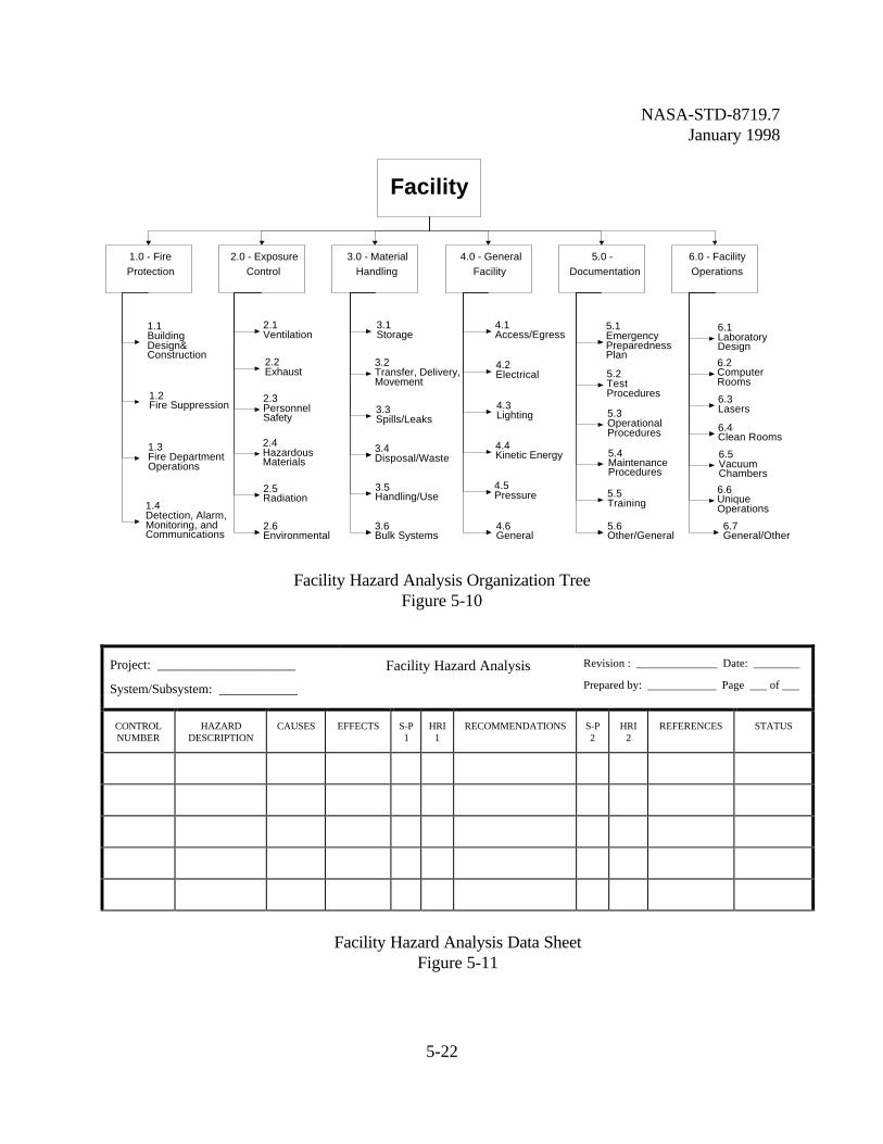
5.3.4.8 Facility Hazard Analysis Data Sheets. The potential hazards identified in the FHAare organized by functional area. They are subdivided into different areas of concern, types ofhazards, and/or design disciplines. This is illustrated in Figure 5-10, FHA Organization Tree. Byorganizing hazards into categories the Safety Engineer can cross reference the various hazard dataentries shown in Figure 5-11, Facility Hazard Analysis Data Sheet. This ensures that each hazardcategory is identified and evaluated, preventing the possibility of over looking the hazard. Thefollowing is an explanation of the various entries in the data sheet:
(a) Heading. The heading on each FHA data sheet identifies the particular analysis. The"Project" for all data sheets should identify the name of the facility or project. The "Date"indicates the most recent version of each data sheet. The "System/Subsystem" will indicate theaspect of the facility covered by the FHA data sheet
(b) Control Number. The first column of the data sheet provides the "Control Number"for that particular hazard. The control number is related to the "System/Subsystem" provided inthe heading, and to the corresponding number found in the FHA Data Sheet Organization onFigure 5-11.
(c) Hazard Description The second column, "Hazard Description," identifies the energysource that generates the hazard. This entry may also indicate the immediate cause for concern,such as a fire/explosion or toxic fumes buildup.
NASA-STD-8719.7January 1998
5-22
Facility
1.0 - FireProtection
2.0 - ExposureControl
3.0 - MaterialHandling
4.0 - GeneralFacility
5.0 -Documentation
6.0 - FacilityOperations
1.1BuildingDesign&Construction
1.2Fire Suppression
2.2Exhaust
2.1Ventilation
3.1Storage
4.1Access/Egress
5.1EmergencyPreparednessPlan
6.1LaboratoryDesign
3.2Transfer, Delivery,Movement
4.2Electrical 5.2
TestProcedures
6.2ComputerRooms
2.3PersonnelSafety
1.3Fire DepartmentOperations
1.4Detection, Alarm,Monitoring, andCommunications
2.4HazardousMaterials
2.5Radiation
2.6Environmental
3.3Spills/Leaks
3.4Disposal/Waste
3.5Handling/Use
3.6Bulk Systems
4.3Lighting
4.6General
4.5Pressure
4.4Kinetic Energy
5.3OperationalProcedures
5.4MaintenanceProcedures
5.5Training
5.6Other/General
6.3Lasers
6.4Clean Rooms
6.5VacuumChambers
6.6UniqueOperations
6.7General/Other
Facility Hazard Analysis Organization TreeFigure 5-10
Project: _____________________
System/Subsystem: ____________
Facility Hazard Analysis Revision : ______________ Date: ________
Prepared by: ____________ Page ___ of ___
CONTROLNUMBER
HAZARDDESCRIPTION
CAUSES EFFECTS S-P1
HRI1
RECOMMENDATIONS S-P2
HRI2
REFERENCES STATUS
Facility Hazard Analysis Data SheetFigure 5-11
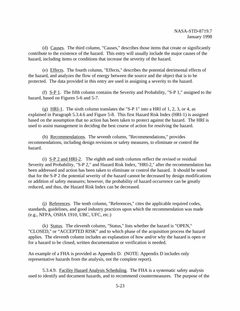
NASA-STD-8719.7January 1998
5-23
(d) Causes. The third column, "Causes," describes those items that create or significantlycontribute to the existence of the hazard. This entry will usually include the major causes of thehazard, including items or conditions that increase the severity of the hazard.
(e) Effects. The fourth column, "Effects," describes the potential detrimental effects ofthe hazard, and analyzes the flow of energy between the source and the object that is to beprotected. The data provided in this entry are used in assigning a severity to the hazard.
(f) S-P 1. The fifth column contains the Severity and Probability, "S-P 1," assigned to thehazard, based on Figures 5-6 and 5-7.
(g) HRI-1. The sixth column translates the "S-P 1" into a HRI of 1, 2, 3, or 4, asexplained in Paragraph 5.3.4.6 and Figure 5-8. This first Hazard Risk Index (HRI-1) is assignedbased on the assumption that no action has been taken to protect against the hazard. The HRI isused to assist management in deciding the best course of action for resolving the hazard.
(h) Recommendations. The seventh column, "Recommendations," providesrecommendations, including design revisions or safety measures, to eliminate or control thehazard.
(i) S-P 2 and HRI-2. The eighth and ninth columns reflect the revised or residualSeverity and Probability, "S-P 2," and Hazard Risk Index, "HRI-2," after the recommendation hasbeen addressed and action has been taken to eliminate or control the hazard. It should be notedthat for the S-P 2 the potential severity of the hazard cannot be decreased by design modificationsor addition of safety measures; however, the probability of hazard occurrence can be greatlyreduced, and thus, the Hazard Risk Index can be decreased.
(j) References. The tenth column, "References," cites the applicable required codes,standards, guidelines, and good industry practices upon which the recommendation was made(e.g., NFPA, OSHA 1910, UBC, UFC, etc.)
(k) Status. The eleventh column, "Status," lists whether the hazard is "OPEN,""CLOSED," or “ACCEPTED RISK” and to which phase of the acquisition process the hazardapplies. The eleventh column includes an explanation of how and/or why the hazard is open orfor a hazard to be closed, written documentation or verification is needed.
An example of a FHA is provided as Appendix D. (NOTE: Appendix D includes onlyrepresentative hazards from the analysis, not the complete report).
5.3.4.9. Facility Hazard Analysis Scheduling. The FHA is a systematic safety analysisused to identify and document hazards, and to recommend countermeasures. The purpose of the
NASA-STD-8719.7January 1998
5-24
FHA is to identify hazards and all accompanying implications, to determine the severity andprobability of the hazards, and to make recommendations for their elimination or control. TheFHA should start in the planning phase so that safety considerations can be included in programplanning, trade-off studies, and selection of design safety requirements. This will help reduce thepossibility of costly design changes later in the development of the facility. The FHA provides abaseline of safety data from which further safety analyses can be conducted.
5.4 DESIGN PHASE
5.4.1. Facility Design. The facility design segment of facility acquisition is the stage inwhich the facility progresses from concept to actual design. For a much more detaileddescription, refer to Chapter 5 of NPG 8820.2, "Facility Project Implementation Handbook." Listed below are some of the activities performed and documentation prepared during theacquisition phase:
• Assignment of a Design Management Team;
• Determination of design parameters, standards, and considerations;
• Preparation of a design criteria package;
• Determination of design costs and funding sources;
• Procurement of Architect-Engineer (A&E) services;
• Value Engineering
• Field Installation Design Management
- Design Reviews (30%, 60%, 90%, and 100%)
- 100% Design (drawings and specifications); and
• Preparation of a Facility Acquisition Plan.
5.4.2. Hazard Analysis Tracking Index. A Hazard Analysis Tracking Index (HATI) (alsoreferred to as a Hazard List Tracking Record (HLTR) in some NASA documentation) is acontinuation of a Facility Hazard Analysis (FHA). The FHA data sheets provide the frameworkfor the HATI. These data sheets are periodically updated to document actions taken to eliminateor control hazards. The HATI is part of the FHA, its purpose is to provide the user with a way totrack the status of hazard resolution. Hazards identified by other hazard analysis techniques suchas Subsystem Hazard Analysis (SSHA), System Hazard Analysis (SHA), or Operation andSupport Hazard Analysis (O&SHA) are also added to the HATI for tracking.
5.5 CONSTRUCTION PHASE
This phase of the acquisition process is concerned not only with construction, but also the check-out of the facility with respect to the design drawings and specifications. Execution of theconstruction phase includes:
NASA-STD-8719.7January 1998
5-25
• Obtaining project approval (Facility Project-Brief Project Document NASA Form1509) and funding (Resources Authority Warrant NASA Form 506A) or authority toadvertise prior to receipt of funds;
• Management of the construction work;
• Completion of the facility;
• Preparation of operations and maintenance instructions and as-built drawings;
• Final inspection and acceptance of the facility construction work; and
• Final cost close-out.
Safety tasks during the construction phase focus on construction worksite safety, ensuring hazardcontrols are properly installed (through the HATI), and identifying hazards at interfaces and thoseresulting from change orders. Safety tasks include:
• Participate in the Pre-Construction Conference to insure the contractor’s constructionsafety plan is appropriately developed;
• Construction shall not proceed until the contractor’s safety plan is approved by thecontracting officer in coordination with the Field Installation Safety Office;
• Ensure the application of all applicable building safety codes including the center’sadopted codes as well as OSHA and NFPA regulations;
• Review equipment installation, operation, and maintenance plans to ensure all designand procedural safety requirements have been met;
• Evaluate mishaps or other losses to determine that adequate corrective action isimplemented;
• Conduct construction or fabrication surveillance to include overseeing of constructionworksite safety, safety program compliance reviews, and scheduled contractdeliverables review and approval; and
• Update the HATI to identify any new hazards or closure of hazards that may resultfrom change orders.
5.5.1 Hazard Resolution Verification. The purpose of the Hazard ResolutionVerification (HRV) is to verify that all the “recommendations” of the FHA data sheets have beenimplemented and all hazards have been eliminated, accepted, or closed. The HRV is an importantstep in facilities ranked with a FRI of 1 because the potential number of hazards, and the severityand probability of hazards are greater. The HRV starts in the Construction Phase because this isthe first phase in which hazards can be field verified for closure. The field inspection/verificationis important to ensure that the safety controls have actually been put into place. The HRV alsocontinues into the Activation Phase to ensure that the facility outfitting meets safety requirements. An example is the performance testing of a laboratory fume hood to ensure proper hood capture.
NASA-STD-8719.7January 1998
5-26
If the procedures in a building involve potential hazards, the HRV can be used to verify that stepsoutlined in a Safety Manual or Chemical Hygiene Plan are actually performed in day-to-dayoperations.
5.6 ACTIVATION PHASE
The final activity in the facility project process is the check-out and activation of the facility thatwas constructed as a result of the design drawings and specification. Some of these activities are:
• Development of the Facility Activation Plan;
• Facility safety review (Operational Readiness Review);
• Preparation of operation and maintenance instructions and as-built drawings;
• Subsystems and integrated systems tests;
• Final inspection and acceptance of the facility construction or installation work;
• Final cost close-out; and
• Facility outfitting. This includes laboratory installation of fume hoods, chemicalStorage cabinets, equipment hookups, workbenches, etc.
5.6.1. Initial System Test / Operational Readiness Review. Facilities constructed forNASA Centers should be scheduled for inspection and acceptance after construction has beencompleted as described in the contract documents. This should occur before the facility isactivated or used to accommodate the intended function. System safety is an integral part of theacceptance phase. Two important system safety steps in facility activation are: initial system testand operational readiness review.
Complex facilities with multiple interfaces, potential unidentified residual hazards, high energysources, and a variety of controls and interlocks may require an Initial System Test (IST) prior tothe Operational Readiness Review (ORR) to verify that all hazards have been identified and eitherremoved or controlled, that the subsystems operate correctly, and that subsystem interfaces havebeen properly designed and constructed. Prior to commencing the IST, a hazard analysis shall beconducted to identify hazards created during testing and the controls devised to eliminate thosehazards or reduce them to an acceptable level. FRI 1 facilities usually are candidates for an IST.
An ORR committee should be convened for facilities where there is a significant degree of risk ofaccident or improper operation that might cause personnel injury or death or serious damage toequipment, buildings, or adjoining areas. ORRs should also be convened if an IST has beenperformed.
The purpose of the ORR is to review the facility hazards documented in the HATI and controls,review the IST results if applicable, verify an initially safe operation, and make recommendations
NASA-STD-8719.7January 1998
5-27
to the Center Director for final decision and approval concerning status of residual hazards andany restrictions or limitations on the operation of the facility. The ORR committee should becomposed of the appropriate facility managers, users, and safety personnel. For less hazardousoperations, the ORR is an informal review by a team composed of construction inspectors, safetypersonnel, and others as appropriate. This team reviews the hazards and controls, verifies aninitially set operation, and makes recommendations to the Facility Project Manager for finaldecision and approval concerning status of residual hazards and any restrictions or limitation onthe operation of the facility.
5.7 OPERATIONS PHASE
The Operations Phase is the normal operations and use of the facility. The normal facilityoperations begin once the facility has been formally approved, and finishes at the time of facilitydisposal. Repair, maintenance, and rehabilitation are normal events during the life of a facility.
During the Operations Phase, the system safety work does not end. The HATI should be updatedas facility changes are made. Any modifications made to the original design, or new activitiesperformed in the facility, should be reviewed by the safety staff to assure that any new hazards ormitigated safety controls are accurately reflected in the HATI. Annual facility walkthroughs alsohelp the safety engineer keep abreast of any changes in the facility. As required, a formalOperating and Support Hazard Analysis may need to be performed of the activities in the facility.
5.8 DISPOSAL PHASE
The Disposal Phase of the facility is the actual decommissioning of the buildings and facilities. Inthe disposal phase of the life cycle the potential safety and environmental aspects should beevaluated. Some of the concerns may be: residual ionizing radiation sources, heavy metals, toxicchemicals, and asbestos. When required, a formal hazard or environmental analysis may beneeded. The results of the analysis and courses of action to abate a hazardous situation should bean integral part of the facility disposal plan. Safety and environmental personnel should monitorhazardous conditions to ensure compliance with applicable laws and regulations.
Safety related concerns during the disposal phase include the procedures to be used fordismantling the facility, the equipment required such as cranes and heavy equipment, securityduring the disposal process, training for the team responsible for dismantling the facility,disposition of the equipment in the facility, disposal of hazardous materials, logistics, and makingthe facility safe and ready for the next tenant (assuming that the facility will not be destroyed). The Facility System Safety Program Plan for the facility will have to be modified to identify theanalysis methodologies appropriate for the decommissioning of the facility. All identified hazardsshould be resolved.
NASA-STD-8719.7January 1998
6-1
CHAPTER 6OTHER FACILITY ACTIVITIES REQUIRING A SYSTEM SAFETY INPUT
6.1 INTRODUCTION
Facility system safety programs that result in the highest practical level of safety within theconstraints of time, cost, and system effectiveness are dependent on emphasis given to otherfacility acquisition plans, procedures, and activities. Operating procedures, maintenanceprocedures, facility acceptance plans, training plans, configuration management plans, emergencymanagement plans, and facility decommissioning plans must be included in the facility acquisitionprogram for the facility to function successfully throughout its life cycle. System safety inputs toeach of these disciplines are described in the following paragraphs.
6.2 OPERATING PROCEDURES
Operating procedures for facility equipment such as air handling equipment, fume hoods,fire/emergency management systems, and fire detection and suppression systems are usuallyprovided by the manufacturer. These procedures, which generally have to be made facility-specific, must be reviewed to assure that appropriate hazard warnings and cautions provided bythe manufacturer are included. Additionally, procedures must be reviewed to ensure that hazardsidentified in either the Facility Hazard Analysis or other facility specific hazards analyses that arerelated to procedures are addressed. Typical hazards identified in Facility Hazard Analysesinclude requirements for PPE; requirements for special tools, certification, or licensing;requirements for operating certain equipment; and requirements for emergency instructionsincluding egress.
6.3 TEST ACTIVITIES
NASA is currently pursuing various advanced missions. To develop the appropriate technologyfor these missions, NASA conducts intensive ground testing. NASA performs both manned(frequently using astronauts as test subjects) and unmanned testing. Manned tests, many times,are conducted in oxygen-enriched and/or pressurized environments or neutral buoyancy tanks. Unmanned tests may use high pressure liquid hydrogen or oxygen, anhydrous ammonia,hydrazine, or other dangerous media. High temperatures, pressures, accelerations, and electricalpotentials are typical in most NASA test operations. This requires a special test safety program. Because the NASA test environment can be hazardous and complex state-of-the-art hardwaresystems are used, the safety organization should develop an integrated, independent test safetyprogram.
Test safety engineers operate at the "nuts and bolts" level and fully understand all systems andsubsystems that will be tested. They also work with members of various divisions to help reach
NASA-STD-8719.7January 1998
6-2
the common goal of achieving a successful test. The safety organization should be completelyautonomous of any test organization and reports to the Center Director. This maintains thenecessary independence that is required for appropriate oversight. Reconciling these seeminglymutually exclusive relationships is key to providing a meaningful safety function.
Safety tasks are diverse over the hardware life cycle of pre-test, test, and post-test activities. Pre-test activities require the use of system safety techniques. Failure modes and effects analyses(FMEAs) and hazard analyses are the primary system safety methods applied for timelyidentification and control of hazards. Safety engineers support test activities through periodicreal-time monitoring of various phases of test conduct. Review of post-test reports close thecircle, furnishing safety information for improved future analyses. (Bahr, 1988)
6.4 MAINTENANCE PROCEDURES
Facility and equipment maintenance procedures must be developed for facilities and theiroperational systems to minimize risk to personnel and the facility. Maintenance activities play animportant role among those normally expected events that occur during the life of a facility and sothey too require procedures for hazardous tasks. Operational certification and calibrationprocedures for equipment such as cranes, fork lift trucks, functional test equipment, electricalcable repair, machinery repair, emergency systems maintenance, and other facility systems oftenrequire incorporation of appropriate warnings, hazards, and cautions. This can be accomplishedby using a system safety approach to identify and control the operational hazards that occurbefore and during the use of such equipment. A system safety approach is essential since not allequipment is dedicated to a particular facility activity nor used by the same operator, and becauseit can be used for multiple facility operations.
A formal Operating & Support Hazard Analysis (O&SHA) should be performed to identifyoperational hazards with a high risk as required by NHB 1700.1 (V1-B), “NASA Safety Policyand Requirements Document.” Equipment maintenance procedures should be provided forequipment that include controls identified in the O&SHA. These operating and maintenanceprocedures are often referred to as Hazardous Operating Procedures. They identify specialcautions and warnings to personnel involved in performing the procedure; authorize standardized,acceptable work practices for maintenance; and verify systems/equipment, instructions forcheckout, servicing, handling, and transportation. The information that is typically found in aHazardous Operating Procedure is summarized below:
• Identification of specific hazards to which personnel will be exposed during theoperation;
• Identification of the operating location for the hazardous task;
• Identification of hazard controls and a means for verifying that they are in place;
NASA-STD-8719.7January 1998
6-3
• Identification of safety precautions where specific guidelines must be observed oractions must be taken to prevent or limit the hazard;
• Identification of organizational elements and facilities required to support theoperation;
• Identification of tools, equipment, and personal protective clothing;
• A list of referenced documents that contain instructions that support the operation;
• Unique safety rules and regulations that must be followed throughout the operation;
• A list of essential personnel required to support the operation;
• Identification of control areas to minimize risk to others;
• Identification of personnel required to be certified or licensed to perform theoperation; and
• Identify emergency instructions.
6.5 FACILITY ACCEPTANCE PLANS
Facility acceptance is generally the responsibility of the Facility Project Manager, the assignedinspector, the contractor, and safety personnel. The objective of this inspection from the safetyperspective is to verify resolution of identified hazards, to identify safety related defects anddeficiencies, to schedule the necessary corrective action, and to update the Hazard Analysis Tracking Index (HATI). When conducting the inspection, safety personnel should verify that thespecified safety features are provided in accordance with recommendations presented in theFacility Hazard Analysis, facility drawings, and specifications. The inspection should also includeidentification of safety deficiencies that could delay the installation of critical facility or missionequipment. It should also include the identification of instances where safety deficiencies wouldimpose undue additional expense. The facility manager normally develops a schedule for work tobe corrected and provides a schedule of the deficiencies to be corrected. When the facilitymanager and safety personnel are satisfied that the deficiencies have been corrected, the finalinspection is scheduled. The final inspection date is generally established by the Facility ProjectManager. The final inspection generally includes a tour of the entire facility project; verificationof the corrected deficiencies previously identified in the HATI and FHA; and inspection ofhardware, equipment, and operations (including installed equipment) for safety compliance. Safety related controls should be checked to assure they are in proper working order. If not, thefinal inspection report should include provisions for identifying those systems where the safetyinspection will be made at a future date. Safety deficiencies not previously identified should alsobe included in the final report and entered in the HATI.
NASA-STD-8719.7January 1998
6-4
6.6 TRAINING PLANS
A well planned training program establishes requirements and minimum certification levels forpersonnel involved in potentially hazardous operations. Training procedures should placenecessary emphasis on the safety aspects for all facility operations to help eliminate one of themost frequent causes of accidents - lack of knowledge or skill. If employees are expected to dotheir work safely, procedures must be developed to identify how the work is accomplished and toensure that they have the knowledge and skill to perform the job in exactly that manner. Therefore, it is the responsibility of safety professionals and facility management to developtraining procedures that encompass the safety needs of each person in the work place.
6.6.1. Operational Training. OSHA 1910.26, Section 21(b)(2), states "the employer shallinstruct each employee in the recognition and avoidance of unsafe conditions and the regulationsapplicable to his/her work environment to control or eliminate any hazards or other exposure toillness or injury." Training procedures are required to ensure personnel are educated in therecognition and avoidance of hazards and should be developed throughout the life cycle of thefacility. Early in the planning and design phases many hazards are identified, through analysis, inthe FHA. These hazards may occur during facility construction, activation, maintenance, ordisposal operations. The control measures identified through analysis are then developed toeliminate or prevent the occurrence or likelihood of accidents/failures. Not only do controlsinclude design, operational, or personnel requirements, but they also include training of personnelto ensure they understand the facility systems and operations that they are going to operate. Forexample, a facility manager should ensure that training procedures are developed for everyoperation within his/her facility. This may include handling and storage of hazardous materials,operation of a laser laboratory, pressurizing flight test articles, operating motorized equipment,and operating electrically energized equipment.
6.6.2 Emergency Training. Training procedures are required for emergency situationsthat may occur within the facility. Such events are unexpected and personnel involved in theemergency response operations need to be able to respond immediately. They must also have theknowledge and skill required to react competently. Training procedures provide facility personnelwho can respond to the emergency with the required information to perform as the situationdictates.
Emergency training procedures should be organized so the various steps or actions performed donot themselves create a hazardous situations. Also, these training events must maintain a logicalframework for demonstrating sound safety practices. The FHA and the O&SHA are two types ofanalyses that may be used to identify what types of emergency procedures are necessary for thefacility and also identify the logical framework for creating emergency procedures. System safetyanalyses ensure that all aspects of facility emergencies are recognized and assist in maintaining asafe and healthy work environment.
NASA-STD-8719.7January 1998
6-5
6.7 CONFIGURATION MANAGEMENT PLANS
The key provision of the Facility System Safety Program Plan should stipulate that an initialsystem safety analysis should be conducted for each facility, that a baseline for controlleddocuments be established, and that these analyses and documents be kept current by an activeConfiguration Management (CM) program. These analyses and the continuous update providedby the CM program provide procedural and risk information to operating personnel whilerecording and maintaining the current status of supporting documentation, equipment, andservices within those facilities. CM implies control and continuous updating of documents andincludes continuous systems safety analysis to assess the impact of change. It is important thatany change to facility hardware, software, or procedures be processed through the CM program. Basic to any CM program is the notification of the change to the affected parties, verification thatno protective measures have been degraded or defeated, and that no new hazards have beenintroduced.
Modifications to facilities are generally initiated by one of four methods. The method selecteddepends on the complexity and magnitude of the anticipated change. These four methods are:
• Administrative Change - Facility modifications that are administrative and do notaffect safety. An example of this type of change is the replacement of a mechanical orelectrical component with a like device (valve, meter, etc.)
• Center Facility Engineer Review Change - Facility changes resulting from a problem orfailure that does not affect the facility baseline documents. These should be reportedand reviewed by safety personnel
• Minor Change not Requiring Design Review - Facility modifications affecting thefacility baseline documents and not requiring the Design Review Process
• Change Controlled by Design Review Process - Facility change requiring majormodification during the Design Review Process
Risk review is another aspect of the CM program and all configuration changes submitted aresubject to a system safety engineering analysis. During this process, standard operatingprocedures, checklists, and engineering drawings are analyzed to assess the impact of the change.
6.8 EMERGENCY MANAGEMENT PLANS
Emergency Management Plans are required in accordance with NPD 8710.1, "NASA EmergencyPreparedness Program Policy."
Work on Emergency Management Plans for new facilities generally starts as early in theacquisition process as practical. The facility design should consider aspects of the proposed
NASA-STD-8719.7January 1998
6-6
facility that can have impact on the level of emergency response capability required, theparameters of possible emergencies, the coordination required with other organizations, andemergency response procedures.
Efforts to ensure adequate preparation for emergency situations should begin during the planningphase for new facilities, modifications to existing facilities, or facility/system rehabilitation. Preliminary Hazard Lists, Facility Hazard Analyses, and other hazard analysis techniques canidentify hazards that can impact emergency response. Frequently recurring hazards includeaccess/egress problems, ventilation and smoke control problems, communication systemdeficiencies, and fire detection/suppression system deficiencies. Guidelines presented to, andguidance presented by, the emergency preparedness planners are intended to help ensure thefacilities and equipment needed to cope effectively with emergency situations are available andadequate.
Typical hazards that have applicability to emergency preparedness include:
• Fire protection equipment is selected/designed considering the emergency responserequirements for the facility.
• Fire and smoke detection devices are located considering the layout and design of thefacilities and the location of fixed hazardous equipment.
• Manual alarm devices that are of a type to discourage inadvertent activation.
• Facility layouts that do not allow accidental flammable liquid or vapor intrusion intoan area where there is a potential for a serious fire or explosion. Specifications tominimize emergency conditions which could result from such hazardous liquid orvapor intrusion must be considered.
• Adequate water pressure is available for fire hydrants and standpipes. Additionally,hydrant locations related to the facility should be reviewed to assure that long hoseruns are not required to reach the most hazardous areas of the facility.
• Roadways to the facility assure adequate access for emergency vehicles.
During the conduct of all Facility Hazard Analyses, the intended use of the facility should bereviewed with the emergency response organization on the NASA Center, and with localemergency response organizations who may provide assistance or back-up in the event of anemergency.

NASA-STD-8719.7January 1998
7-1
CHAPTER 7OTHER HAZARD ANALYSIS METHODOLOGIES
7.1 INTRODUCTION
Once initial system safety efforts are in progress, it may become necessary to do more in-depthanalysis for the purpose of accurately assessing risk and controlling hazards. Eight of the morecommon in-depth risk analysis methodologies are described in the following paragraphs; any or allmay be useful, depending on the facility and system life cycle phase, application, and operatingenvironments.
7.2 ENERGY TRACE BARRIER ANALYSIS
7.2.1. Description. An Energy Trace Barrier Analysis (ETBA) is a qualitative analysismethodology used to develop more detailed knowledge of hazards. This technique shown inFigure 7-1 approaches the discovery of hazards by tracing the flows of energy into, through, andback out of a facility, system or operation. It is based upon the premises that:
• Mishaps arise from the risks within an operation.• Mishaps interrupt or degrade the operation.• Mishaps are an unwanted transfer of energy.• The unwanted transfer of energy that produces injury to persons or property is due to
a lack of barriers or controls over the energy.
Too soon/lateToo much/little
Too fast/slow
Uneven/reversed
Wrong place
Define systemoperation
List findingson FHA
Documentfindings/repeatfor each source
Select energytype checklist
Test energyconverter
against flowproblem list
Pinpointenergy INPUTinto system
Pinpointwhere energy
will WORK
Identifyplanned flow
paths
Select energytype to beanalyzed
Too soon/late
Too much/little
Too fast/slow
Uneven/reversed
Combined/separated
Wrong place
Test PATHbarriers
against flowproblem list
Combined separated
ThermalToxicMechanicalRadiation
CorrosiveAsphyxiant
PeopleEquipment
EnvironmentPublic
Identify effectson vulnerable
exposures
Definevulnerableexposures
(tartets)
Hardware
Procedures
Warnings
Define plannedbarriers to
control flow
Energy Trace Barrier Analysis ProcedureFigure 7-1

NASA-STD-8719.7January 1998
7-2
The ETBA process is particularly desirable and useful since it can be applied at any stage of theproject to facilitate detailed analysis of those hazards discovered late in the project as well asthose found at the beginning. The objective of ETBA is to find unsuspected hazards throughmethodical tracing of energy flows in the planned operation and across subsystem interfaces tolocate potentially harmful diversions.
Each type of energy source, summarized in Table 7-1, should be considered individually from theperspective of the operations components and whatever subsystem energy control strategy mayexist. The operation needs to be analyzed at the input/use/output level for each energy type todetermine if the operation's plan or design addresses realistic potential control problems andsatisfactorily controls them.
ETBA is used when concern over possible unacceptable loss indicates a need for betterunderstanding of the operation. This is particularly true when lethal or significantly destructiveenergy flows characterize the operation and experience with the change or operation does notexist, or there has been a high loss rate, or behavior of certain energy interfaces is not known. ETBA is feasible because it is easy to identify the energy sources in almost any circumstance; thedrawback is that performing an ETBA requires detailed familiarity with the operation or system. ETBA requires the services of someone who intimately understands the operation and can traceenergies and barriers/controls thoroughly.
The ETBA is performed by tracing the sequence and logic of energy flow through the operation. For each energy type, the flow must be tracked to each transfer or use point, and each physical orprocedural barrier to the energy must be considered to determine what harmful outcomes arelikely to occur when:
• Too much or too little energy flows;• The energy flows too soon, too late, or not at all;• The energy flow is blocked or impeded in its pathway;• The energy flow conflicts with another energy flow at a transfer or use point; and• A barrier degrades, is disturbed, or does not function at all.
For a mishap to occur there must be an energy source with a release flow of energy to a target inthe absence of adequate barriers. The flow or transfer of energy is the path between the energysource and the target or component of the operation being protected.

NASA-STD-8719.7January 1998
7-3
Table 7-1Energy Types and Examples for Energy Traces
Caused by Internal Events:
1. Electricalac/dc flowsstored electric energyelectromagnetic radiationstatic charges/flows
2. Mass/Gravity/Heightfalls and dropsfalling objectsfalling hazardous materials
3. Rotational Kineticmachineryfans
4. Pressure/Volume & Kinetic Displacementcontainer ruptures and explosionsvacuum creationliquids spill/floodvapor expansion
5. Linear Kineticprojectilesrams, moving partsshear pressvehicular movements, prints, pre-stressed members
6. Chemical Reactionscorrosion, oxidation, combustion, orinteractions among deposited materials,polymerization,decomposition,toxic asphyxiant, anesthetic

NASA-STD-8719.7January 1998
7-4
Table 7-1 (cont.)Energy Types and Examples for Energy Traces
7. Thermalheat, coldalternate heat/coldradiation/conduction/convection, sublimation
8. Etiologicviral,bacterial,fungal
9. Ionizing radiationgamma,alpha,beta
10. Noise and Vibration
11. Human Interactions
Caused By External Environmental Events:1. Terrestrial
earthquake, flood, landslidesubsidence, compaction, cave-ins, water table
Caused By External Events1. Radiation, explosions, projectiles,
noise, vibration, fire
2. Atmosphericwind, rain, snow, lightning,hail, and acid rain

NASA-STD-8719.7January 1998
7-5
7.2.2. Results. In performing ETBA, an engineer develops and maintains a listing ofenergy sources and the hazards associated with each energy form source. Identified hazards areincluded in the Facility Hazard Analysis (FHA), or the Hazard Analysis Tracking Index (HATI) ifthe FHA is complete.
7.3 HAZARD AND OPERABILITY STUDY
7.3.1. Description. The Hazard and Operability (HAZOP) Study is a qualitative methodof analysis used in identifying risk related to highly hazardous substances. The method provides ameans of identifying a multitude of process hazards. It is used to identify potential hazards andoperability problems early in the acquisition cycle at the time of design development of a process. Since the method can be applied early, the potential cost needed to eliminate or correct thehazard is minimized. The HAZOP is performed by an interdisciplinary team of experts whosystematically examine each part of a process. This team identifies how deviations from thedesign intent can occur and whether the collective or individual deviations can create hazards.
The HAZOP is a structured group analysis technique for stimulating one's imagination in order toidentify and assess the significance of all the ways a process unit can malfunction or be improperlyoperated. Its purpose is to identify potential process hazards due to system interactions orexceptional operating conditions.
The analysis objectives are to identify deviations from the design intent of the system. Then theanalyst determines the safety concerns associated with the identified deviations. Finally,recommendations are proposed for resolving safety concerns or accepting risk. The HAZOPprocess is shown in Figure 7-2 below.
CollectData
SelectTeam
ConductHAZOPAnalysis
DocumentResults
TrackImplementation
Define ObjectiveAnd Scope
HAZOP ProcessFigure 7-2

NASA-STD-8719.7January 1998
7-6
An optimum team should range in size from four to eight members and include designers,operators, and users.
The first step in a HAZOP is to identify the "node" to be analyzed. Some of the key items used inselecting nodes are:
• The next design change placed on the system,
• When a significant change of state occurs,
• Separate equipment items, and
• Different processes
Once a node has been selected, it is analyzed with respect to guide words with the processconditions. Guide words (no, more, less, reverse, etc.) are coupled with process conditions (flow,pressure, temperature, etc.). Table 7-2 offers a simplified application.
When organizing a HAZOP team one should consider the members' experience and background. Once a guide word is combined with each process condition the team brainstorms the possibledeviations leading to bad consequences. One example is high pressure leads to:
• Death, personnel injury.
• Property damage.
• Environmental damage.
• Operational damage.
Table 7-2 - Guide/Process Condition
GUIDE WORD
NoMore (High, Long)Less (Low, Short)As Well AsPart ofReverseOther Than
PROCESS CONDITION
FlowPressureTemperatureLevelTimeCompositionpH
Guide Word plus Process Condition = Deviation

NASA-STD-8719.7January 1998
7-7
This determines the worst case credible effect on the node, taking into consideration single failureand ignoring safeguards already in place. This helps the analyst assess existing safeguards orpropose additional safeguards if required.
7.3.2. Results. When the analysis phase is completed and all outstanding issues areresolved, the conclusions are prepared and a tabulation of recommended actions are prepared andsubmitted. Figure 7-3 shows a typical HAZOP worksheet. Sources of information typicallyinclude piping and hardware drawings, facility drawings, procedures, safety hazard analysisreports, and accident & investigation reports. The advantages of a HAZOP are that it is a verycomprehensive hardware review, it is good for complex systems, and it provides very detailedresults. The disadvantages of a HAZOP are that it is very time consuming, expensive, and maynot pick up on multiple failures.
HAZOP WorksheetFigure 7-3
The HAZOP is not a quantitative assessment and consequence probabilities are not normally partof the analysis unless other quantitative techniques such as fault trees are integrated into theoverall effort; however, the results of the analysis are directly proportional to the extent that theHAZOP team understands the process and has defined all of the process elements. As statedearlier, HAZOP is only one method of hazard evaluation. Other methods may be more suited to afacility assessment depending on the needs of the project.
Guideword Cause Effect Type Safeguards Recommen-dations
Actions
1 2 3 4 5 6
7 8 9 10

NASA-STD-8719.7January 1998
7-8
7.4 SUBSYSTEM HAZARD ANALYSIS
7.4.1. Description. The Subsystem Hazard Analysis (SSHA) is performed to identifydesign hazards in subsystems. For a facility, subsystems could include an industrial laser, acomputer controlled fire detection and suppression system, a vacuum chamber or special purposetest equipment. The requirement for a SSHA is usually identified in the concept phase of a systemor facility. Due to the complexity of the analysis, the analysis is usually specified in a procurementspecification then completed by the equipment/subsystem manufacturer.
The analysis should find functional failures of subsystems that could result in accidental loss.Component and equipment failures or faults, and human errors that establish a hazard due to thefunctioning of the subsystem are analyzed. The analysis is completed by reviewing designdrawings, engineering schematics, and specifications.
The SSHA should be completed no later than the beginning of system definition phase of thesystem life cycle. As the system and related subsystems are further defined during systemdefinition and development, the analysis should be revised. A sample sheet from a SSHAcompleted for a signal system is provided as Figure 7-4 (Roland and Moriarty, 1990).
ANALYSIS TYPE:: SUBSYSTEM HAZARD ANALYSIS
SYSTEM SIGNAL SYSTEM PREPARED BY _______________________________________
SUB-SYSTEM POWER DATE _________________ SHEET ________ OF __________
ITEMNO.
COM-PONENT
FUNCTION HAZARDDESCRIPTION
HAZARDEFFECTS
HAZARDCATEGORY
& PROB.
RECOMMENDEDCONTROL
RESOLU-TION
1 AUTO-MATICTRANS-FERSWITCH
AUTOMATICALLYPROVIDESPOWER FROMEITHER NORMALOR EMERGENCYSOURCE
AUTOMATICTRANSFERSWITCH WILLNOT SHIFT FROMPOWER SOURCETO EMERGENCYPOWER WHENPOWER SOURCEIS LOST
SIGNALFAILS
1D PROVIDE “VITAL”SIGNALS TOSHIFT ALLSIGNALS TORED (STOP)CONDITIONWHEN NOPOWER ISAVAILABLE
2 AUTO-MATICTRANS-FERSWITCH
AUTOMATICALLYPROVIDESPOWER FROMEITHER NORMALOR EMERGENCYSOURCE
NO POWER ISAVAILABLE FROMEITHER NORMALOR EMERGENCYPOWER SOURCE
SIGNALFAILS
1E PROVIDE BACKUP BATTERYPOWER
Completed Signal System SSHA FormFigure 7-4

NASA-STD-8719.7January 1998
7-9
7.4.2. Results. The SSHA identifies hazards to personnel, equipment, facilities, andprogram resources caused by loss of function, energy sources, hardware failures, personnelactions or inactions, software deficiencies, interaction of components, inherent designcharacteristics, incompatible materials, and environmental conditions (within the subsystem).
Results of an SSHA are referred to the managing activity for inclusion in the hazard analysisdocumentation. Unresolved hazards are listed in the HATI.
7.5 SYSTEM HAZARD ANALYSIS
7.5.1 Description. The System Hazard Analysis (SHA) examines the interfaces betweensubsystems. In so doing, it must integrate the outputs of the SSHA. It should identify safetyproblem areas of the total system design including safety critical human errors, and assess totalsystem risk. Emphasis is placed on examining the interactions of the subsystems. The SHAshould examine subsystem relationships for:
• Compliance with safety criteria specified in subsystem requirements documents.
• Sets of hazardous events, independent or dependent to include failures of safetydevices and common cause conditions or events that can result in system or facilityhazards.
• Degradation of safety of the overall system or facility from normal operation of asubsystem.
• Software control functions that may adversely affect system risk due to softwarefaults.
• Human control functions that may affect risk through human faults.
• The SHA begins during the early design phases. The SHA is updated when interfacesare defined and continues on through to the beginning of system operation.
7.5.2 Results. Results of the SHA are presented in tabular form. Identified hazards whichare not resolved are included in the HATI. Figure 7-5 shows the results of a SHA for a tunnelpumping system.
7.6 OPERATING AND SUPPORT HAZARD ANALYSIS
7.6.1. Description. Most safety analyses are directed towards uncovering designproblems associated with hardware. This is not the intent of an Operating and Support HazardAnalysis (O&SHA). The purpose of the O&SHA is to identify and evaluate the hazards associatedwith the environment, personnel, procedures, and equipment involved throughout the operation ofa system/element. The O&SHA identifies, documents, and evaluates hazards resulting from theimplementation of operations or tasks performed by persons and considers:
• The planned system configuration at each phase of activity,
• The facility interfaces,

NASA-STD-8719.7January 1998
7-10
• The planned environments, the support tools, or other equipment specified for use,
• Operation or task sequence,
• Concurrent task effects and limitations,
• Biotechnological factors,
• Regulatory or contractually specified personnel safety and health requirements, and
• The potential for unplanned events including hazards introduced by human error.
The O&SHA identifies the safety requirements (or alternatives) needed to eliminate identifiedhazards, or to reduce the associated risk to a level which is acceptable.
To perform an O&SHA, pertinent data such as procedures, sequence diagrams, operation andfunctional analyses, equipment layout diagrams, systems and subsystem design specifications,equipment and interface drawings, operations and maintenance instructions, and human factorsengineering data should be obtained if available. A worksheet is commonly used to develop thehazards. It is similar to the FHA but with an operational event as the primary categorizingfunction. Operational events are sets of sequenced actions for operating, assembling, maintaining,repairing, calibrating, testing, transporting, handling, installing, or removing an assembly,component, or system. These events are generally documented in procedures. An analysis of theprocedures is completed to ensure that:
ANALYSIS TYPE:: SYSTEM HAZARD ANALYSIS
SYSTEM PUMPING SYSTEM PREPARED BY
SUB-SYSTEM PUMP, CONTROLLER POWER____ DATE _________________ SHEET ________________ OF _____________
ITEMNO.
COM-PONENT
FUNCTION HAZARDDESCRIPTION
HAZARDEFFECTS
HAZARDCATEGORY
& PROB.
RECOMMENDEDCONTROL
RESOLU-TION
1 POWERCABLE
TRANSFERSPOWERBETWEENSOURCEAND PUMP
PUMPCONTROLLERPOWER CABLEFAILS - LACKOF POWER
LOSS OFPUMPINGCAPABILITY -WATER FLOODSTUNNEL
1D PROVIDEREDUNDANTPOWER CABLE
2 PUMPCON-TROLLER
PROVIDESCONTROL OFPUMPOPERATION
PUMP REMAINSONCONTINUOUSLY - PUMPBURNS OUT
WATER FLOODSTUNNEL
1B PROVIDE LOWWATER CUT-OFF FOR PUMP
Completed Tunnel Pumping System SHA FormFigure 7-5

NASA-STD-8719.7January 1998
7-11
• Required tasks, human-machine-environment and interpersonal relationships, and thesequences of operational steps will not lead to a mishap.
• Completing the procedure does not expose personnel to any hazards.
• Instructions are clear and effective and do not induce errors that could lead tomishaps.
• Alternative actions a person could take which could result in mishaps are precluded, orthe effects of such actions are minimized.
• Safety-critical steps are highlighted with warnings and cautions.
• No extraordinary mental or physical demands are made for programmed operations.
• Times for accomplishment of safety-critical tasks are realistic.
The following should also be accomplished to ensure the procedures are safe:
• Examine the procedure and each step within the procedure for effect, necessity, andclarity. Personnel tend to take shortcuts in order to avoid arduous, lengthy,uncomfortable, or ambiguous procedures. The shortcuts can sometimes lead to errorsand mishaps.
• Examine each procedure and each step, no matter how simple it appears, forpossibilities of error, alternative actions, and adverse results.
• Determine whether or not special training, knowledge, or capability is required whichthe prospective operator might not have.
• Review the causes of error and attempt to eliminate or minimize the possibilities of asmany of them as possible.
• Verify the proposed procedures by examining, demonstrating, and testing.
After the operating procedures are analyzed, the procedures should be verified. This verificationshould be done by persons not involved in writing or analyzing the procedures. A checklistshould be used to assist in verifying the procedures. In addition, the analyst should try to performthe procedures as prescribed by the author of the procedures and then try to anticipate anyalternative actions the user might take. The person performing the procedures should verify thatsafeguards will work as intended, that emergency stop systems can be reached and will stop anoperation when they are supposed to, that detection and warning devices operate, that personnelprotective equipment can be reached and donned within planned lengths of time, and thatemergency routes and exits are practical.
7.6.2. Results. An O&SHA is very useful and can give valuable information, such as:
• Corrective or preventive measures that should be taken in order to minimize thepossibilities of an error resulting in a mishap.

NASA-STD-8719.7January 1998
7-12
• Recommendations for changes or improvements in hardware or procedures in order toimprove efficiency and safety.
• Development of warning and caution notes to be included in the most effective placesin the procedures.
• Requirements for special information or training of personnel who will carry out theprocedures.
• Recommendations for special equipment, such as personnel protective clothing ordevices, which would be required for the operations to be undertaken.
Figure 7-6 shows the results of an O&SHA worksheet.
7.7 FAULT TREE ANALYSIS
7.7.1. Description. A fault tree analysis (FTA) can be simply described as an analyticaltechnique, whereby an undesired state of the system is specified (usually a state that is criticalfrom a safety standpoint), and the system is then analyzed in the context of its environment andoperation to find all credible ways in which the undesired event can occur. The fault tree itself isa graphic model of the various parallel and sequential combinations of faults that will result in theoccurrence of the predefined undesired event. The faults can be events that are associated with
OPERATING & SUPPORT HAZARD ANALYSIS BATTERY BOX
STATION: Technician DATE: ________________
OPERATIONAL MODE: Run SHEET NO: ____ OF ____
ID#
Process/Task HazardousCondition
Cause Effect HazardCategory
HazardProbability
Status/Recommendation
1. Connecting/disconnecting emergencylights to sealedconnections onbattery box.
Water entersintoconnector
Connectorscracked orseal isdefective.
Electricalshock topersonnel.
1-Catastrophic B- Possible Daily inspection of connectors;Replace when deficiencies aredetected.
2. Removal andreplacement ofbattery box.
Fall onpersonnel.
Fall onequipment.
Lifting lugsfail.
Nylonwebbingfails.
Injury topersonnel.
Damage toequipment.
1-Catastrophic B- Possible A. Assure integrity of weld lugs.
B. Perform regular inspections ofwebbing; Replace when frayed orworn.
C. Train personnel in saferaising/lowering box.
D. Train personnel to stand clearwhen box is being raised orlowered.
Example O&SHA WorksheetFigure 7-6

NASA-STD-8719.7January 1998
7-13
component hardware failures, human errors, or any other pertinent events which can lead to theundesired event. A fault tree thus depicts the logical interrelationships of basic events that lead tothe undesired event which is the top event of the fault tree.
It is important to understand that a fault tree is not a model of all possible system failures or allpossible causes of system failure. A fault tree is tailored to its top event which corresponds tosome particular system failure mode, and the fault tree thus includes only those faults thatcontribute to this top event. Moreover, these faults are not exhaustive, they cover only the mostcredible faults assessed by the analyst.
It is also important to point out that a fault tree is not in itself a quantitative model. It is aqualitative model that can be evaluated quantitatively and often is. This qualitative aspect, ofcourse, is true of virtually all varieties of system models. The fact that a fault tree is a particularlyconvenient model to quantify does not change the qualitative nature of the model itself.
A fault tree is a complex of entities known as "gates" which serve to permit or inhibit the passageof fault logic up the tree. The gates show the relationship of events needed for the occurrence ofa "higher" event which is the "output" of the gate; the "lower" events are the "inputs" to the gate. The gate symbol denotes the type of relationship of the input events required for the outputevent. Thus, gates are somewhat analogous to switches in an electrical circuit or two valves in apiping layout. Figure 7-7 shows an example fault tree.
F IR E R E L A T E DT R A N S IT C A S U A L IT Y
O C C U R S
F IR E / S M O K E I SN O T A C T I V E L YS U P P R E S S E D
IN D I V I D U A LF A I L S T O
E V A C U A T EA R E A
H A Z A R D O U SC O N D IT IO N S
P R E S E N TIN A R E A
R A I L F I R E /S M O K E
IN C ID E N TO C C U R S
B U S F IR E /S M O K E
IN C ID E N TO C C U R S
IN D I V I D U A L I SN O T R E S C U E D
IN D I V I D U A LF A I L S T O
R E M O V E S E L F
F IR E / S M O K EIN C ID E N TO C C U R S
F IR E / S M O K EIN C ID E N T N O T
S U P P R E S E S O RC O N T A IN E D
a n d
a n d
o r
o ro ro r
F IR E / S M O K E I SN O T
P A S S I V E L YS U P R E S S E D
F IR E / S M O K E I SN O T
C O N T A IN E D
IN D I V I D U A L F A I L ST O E V A C U A T E
R IG H T O F W A Y
IN D I V I D U A L F A I L ST O E V A C U A T E
V E H IC L E
IN D I V I D U A L F A I L ST O E V A C U A T E
S T A T IO N
Example Fault TreeFigure 7-7

NASA-STD-8719.7January 1998
7-14
7.7.2. Results The output of a FTA is a graphic functional failure representative of thesystem or facility. Though the FTA itself is qualitative, quantitative data can be annotated to thetree in the form of event or component failure probabilities, thus quantifying the FTA.
7.8 FAILURE MODE AND EFFECTS ANALYSIS
7.8.1. Description. The Failure Mode and Effects Analysis (FMEA) is a reliabilityanalysis. The focus of the analysis is on single events or component failures that will cause a stateof unreliability in the system (Roland and Moriarty, 1990). The objective of the FMEA is to vieweach identifiable component in the system in the context of two questions:
• How can the component fail?
• What will be the results of this failure downstream in the system or subsystem?
This effort can improve knowledge of potential component, subsystem, or system failures thatwere found by the FHA. The FMEA is used to methodically track each component's major failureeffects into other subsystems and to develop an understanding of the hazardous impact on onecomponent's failure on the rest of the system. As with the SSHA, this analysis methodologyrequires in-depth knowledge of the system, and is generally specified in a procurementspecification and then completed by the system or equipment manufacturer.
FMEA analysis is conducted by asking each of the two above cited questions in relation tocomponents and then projecting the likely physical and functional effects of the failures on otherparts of the system. Effects of failure are stated in terms of associated damage or malfunctionaccompanied by qualitative assessments of frequency and severity suitable for Hazard RiskIndicator (HRI) ranking.
7.8.2. Results. The FMEA output is a columnar worksheet shown such as the one inFigure 7-8. An HRI code for each item may be substituted for the “Probability of Failure". Oneof the strengths of FMEA is that it promotes identification of problems associated with theinterface of subsystems and/or components. Using the specified output format, detected hazardswill be described for characteristics and recommended control action(s). Though the FMEA isqualitative, failure probabilities can be included for decision making purpose.
7.9 SOFTWARE HAZARD ANALYSIS
7.9.1. Description. The traditional approach to the hazard analysis of complexelectromechanical systems is to treat electronic devices that process or originate system controlsignal as black boxes. This approach precludes analysis of the internal functioning of the box. Output reliability of the box is established relative to input and this value inserted into the systemmodel as a quantitative representation of a pseudo-mechanical component of the system. Whenwe replace the box with a small computer, processing instructions that have been permanentlyinstalled in the memory, we have quite another situation. If the software containing the

NASA-STD-8719.7January 1998
7-15
instructions is error or fault free, then this component cannot fail and the statistical concept ofmeasuring stochastic wearouts has no meaning. However, the software instructions may containfaults. This possibility will require an analysis of the computer program code that has becomeinstructions to the hardware system (Roland and Moriarty, 1990).
FAILURE EFFECT ON
COMPONENTNAME ANDNUMBER
FUNCTION FAILURE MODE ANDCAUSE
NEXT HIGHERASSEMBLY
END ITEMPRODUCT
PROBABILITYOF FAILURE
(Σ X 10-6)
CORRECTIVEACTION AVAILABLEOR RECOMMENDED
Cover Cap Keeps coffee from
being thrownabout: keep userfrom gettingfingers into capwhere they couldbe cut by rotor.
Plastic fractures andparts separate. Brittle plastic droppedon hard surfaces,stepped on, orsubjected toexcessive force whenbeing put in place.
None None 1 Select plastic whichis not brittle.
Switch Activating arm (1)
User depressesand holds downfree end in accesshole to switchwhich operatesmill.
Breaks off cap due torough handling byuser,. being steppedon, or dropped.
May causecap toweaken andbreak if armbreaks off incap.
May makeproductunusable.
100 Redesign. Putswitch under cap,thereby eliminatingarea.
Case Case,plastic (1)
Major structuralpart which holdsother assembliestogether: protectsagainst contactwith moving andelectrical parts.
Could be broken byimpact or crushing.
Resultantsharpedges andpoints; maymake itunusable.
0.5 Use impact resistantplastic.
Vibrationdampers (2)
Brittle pads incase. Reductionof vibration andnoise byseparating metalmotor frame fromplastic case.
Deterioration ofrubber. Could be lostsince they are notglued in place.
Fatigue tobrittle plastic.
Excessivevibrationand noise.
0.01 Glue in place.
Example Failure Modes and Effects AnalysisFigure 7-8

NASA-STD-8719.7January 1998
7-16
Control systems and control computers are usually in a high state of flux. Both hardware andsoftware need to be analyzed for all faults and failures, including using probabilistic riskassessment techniques. Because of potentially frequent changes, which are relatively easy tomake compared to hardware changes, control systems and software need to be under strictchange control, as per the Center configuration management plan. Software is coded byprogrammers working to a specification set forth by system designers. Software faults may takethree forms.
• The so-called honest errors made by the programmer in coding the softwarespecification. These are simple mistakes in the coding process that result in thesoftware behaving in a manner other than that which the programmer intended.
• Faults due to incorrect software specifications or the programmer's interpretation ofthese specifications. These errors may result from system designer's lack of fullunderstanding of system function or from the programmer's failure to fullycomprehend the manner in which the software will be implemented or the instructionsexecuted. In this type of fault the software statements are written as intended by theprogrammer.
• Faults due to hardware failure. Hardware failures may change software coding. Thussuch software faults are secondary in that they originate outside the software.
A software hazard may be one of the following four types:
• An undesired signal causes an unwanted event in the system functional process.
• An undesired signal causes an out-of-sequence event.
• An undesired signal prevents the occurrence of a needed event.
• An undesired signal causes an event that in magnitude or direction is out of tolerance.
7.9.2. Results. The results of the software analysis are as varied as the analysesthemselves. Usually the data results are presented in tabular form. Graphs can also be used todepict causal relationships.

NASA-STD-8719.7January 1998
7-17
7.10 HAZARD ANALYSIS SCHEDULES
Figure 7-9 indicates the most appropriate time that the various hazard analyses can be performedthroughout the facility life cycle. Obviously, many of them overlap during the facility life cycle.
REQUIREMENTS PLANNING DESIGN CONSTRUCTION ACTIVATION OPERATION DISPOSAL
FACILITY RISK INDICATOR (FRI)
ENERGY TRACE BARRIER ANALYSIS (ETBA)
PRELIMINARY HAZARD LIST (PHL)
FACILITY SAFETY MANAGEMENT PLAN (SMP)
FACILITY HAZARD ANALYSIS (FHA)
HAZARD ANALYSIS TRACKING INDEX (HATI)
HAZARD RESOLUTION VERIFICATION
HAZARD and OPERABILITY (HAZOP) STUDY
SUBSYSTEM HAZARD ANALYSIS (SSHA)
SYSTEM HAZARD ANALYSIS (SHA)
OPERATING and SUPPORT HAZARDANALYSIS (O&SHA)
FAULT TREE ANALYSIS (FTA)
FAILURE MODE and EFFECTS ANALYSIS(FMEA)
ACTIVITY
SOFTWARE HAZARD ANALYSIS
REQUIRED SAFETY ACTIVITY
REQUIRED FOLLOW-ON SAFETY ACTIVITY
OTHER HAZARD ANALYSIS
OTHER HAZARD ANALYSIS FOLLOW-ON
UPDATE
Facility System Safety Milestone ActivitiesFigure 7-9

NASA -STS-8719.7January 1998
A-1
APPENDIX ATYPICAL ENERGY SOURCES CHECKLIST
A. Acoustical Radiation
Equipment NoiseUltrasonic CleanersCompressors
B. Corrosive
AcidsCausticsNatural Chemicals (Soil, Air, Water)Decontamination Solutions
C. Electrical
Battery BanksDiesel UnitsHigh LinesTransformersWiringSwitchgearUnderground WiringCable RunsService Outlets and FittingsPumpsMotorsHeatersHigh Voltage SourcesElectrostatic Sources (low humidity)
D. Electromagnetic and Particulate Radiation
Radioactive SourcesWaste and ScrapContaminationIrradiated Experimental and Reactor EquipmentElectric FurnaceBlacklight (e.g., Magniflux)
LaserMedical X-rayRadiography Equipment & SourcesWeldingElectric Arc - Other (High Current Circuits)Electron BeamRadarAlternating Current (AC) Motors
E. Explosive Pyrophoric
CapsPrimer CordDynamitePower MetallurgyDustsHydrogen (Inc. Battery Banks and Water Electrolysis)Gases-OtherNitratesElectric SquibsPeroxides-SuperoxidesPropellant
F. Thermal (Except Radiant)
ConvectionHeavy Metal Weld PreheatExposed Steam PipesElectric HeatersFire BoxesLead Melting PotElectrical Wiring & EquipmentFurnaces

NASA -STS-8719.7January 1998
A-2
G. Flammable Materials
Packing MaterialsRagsGasoline (Storage & in Vehicles)Lubrication OilCoolant OilPaint SolventDiesel FuelBuildings and ContentsTrailers and ContentsGreaseHydrogen (Including Battery Banks)Gases - OtherSpray PaintSolvent Vats
H. Kinetic-Linear
CarsTrucksBusesFork LiftsCartsDolliesTrainsSurfacesObstructionsShearsPressesCrane Loads in MotionPressure Vessel BlowdownPower Assisted Driving ToolsMonorails
I. Mass, Gravity, Height
Human EffortsStairsLiftsCranesBuckets and LaddersTrucksSlingsHoistsElevatorsJacksScaffolds and LaddersCrane CabsPitsExcavated DoorsElevated DoorsCanalsVessels
J. Kinetic-Rotational
CentrifugesMotorsPumpsCooling Tower FansCafeteria EquipmentLaundry EquipmentGearsShop Equipment (Grinders, Saws,
Brushes, etc.)Floor Polishers

NASA -STS-8719.7January 1998
A-3
K. Pressure-Volume/K-Constant-Distance
Test Loops and FacilitiesGas BottlesPressure VesselsCoiled SpringsStressed MembersGas Receivers
L. Thermal Radiation
FurnacesBoilersSteam LinesLaboratory and Pilot Plant EquipmentSolarBoilersHeated Surge TanksAutoclaves
M. Toxic Pathogenic
AcetoneFluoridesCarbon MonoxideLeadAmmonia and CompoundsAsbestosTrichlorethyleneDusts and ParticulatePesticides-Herbicides-InsecticidesBacteriaBeryllium and CompoundsChlorine and CompoundsDecontamination SolutionsSandblasting OperationsMetal PlatingAsphyxiation-Drowning
N. Nuclear
VaultsTemporary Storage AreasReceiving AreasShipping AreasCasksBurial GroundStorage RacksCanals in-Tank Storage AreasDolliesTrucksHand CarryCranesLiftsCommercialShopsHot CellsAssembly AreasInspection AreasTest RigsReactorsCritical FacilitiesSubcritical FacilitiesLaboratoriesPilot Plants

NASA -STS-8719.7January 1998
B-1
APPENDIX BPRELIMINARY HAZARD LIST EXAMPLE
GENERAL LABORATORY FACILITY
AREAS OF CONCERN/SAFETY CONSIDERATIONS
(1) Building Materials· Compatibility· Flammability· Structural integrity
(2) Access/Egress· Emergency - evacuation, fire fighting, rescue· Panic hardware· Restricted - security, clean rooms· Handicapped/disabled· Operations and maintenance· Inspection· Life safety code requirements
(3) Utilities· Location· Controls/shutoffs· Electrical power supply· Water supply· Sanitary/sewer· Natural gas· Special systems - bulk gas
(4) Ventilation· Heating· Air conditioning· Clean room environment· Filters/dust control· Humidity control· General exhaust· Emergency· Recirculation/migration/reentrainment
(5) Electrical· Emergency power· Electrostatic discharge

NASA -STS-8719.7January 1998
B-2
(5) Electrical (Continued)· Shock· Wiring· Switchgear· Shutoffs/breakers· Wires/cables under raised floor· Intra- and inter-room cable management/computer networks· Grounding/bonding· Insulation· Cathodic protection· Lasers - high energy power supply, capacitors, interlocks· Lock-out / tag-out
(6) Lighting· Ambient· Emergency· Exit· Security
(7) Fire Protection· Fire/smoke detection· Pull stations· Alarms/annunciation· Automatic fire suppression· Extinguisher selection/location· Standpipe hose connections· Siamese connections· Hydrants· Smoke management· Fire resistive construction· Fire barrier design/construction· Compartmentalization / isolation from different occupancies· Fire department access
(8) Monitoring· System/utility - pressure, temperature, flow, voltage, grounds· Environmental - air quality, temperature, humidity· Security· Fire/smoke detection· Hazardous gas/vapor detection· Leak detection· Alarms/annunciation

NASA -STS-8719.7January 1998
B-3
(9) Communications· Public address· Emergency - fire department, police, medical services· Alarms/central station
(10) General· Stairs/railings· Traffic· Sidewalks· Loading/unloading· Trailer pads· Height - rooftop observation dome, roof mounted antennae
(11) Natural Phenomena· High wind· Snow· Extreme temperatures· Floods· Lightning· Earthquake
(12) Kinetic/Mechanical· Sparks/friction· Overhead cranes· Machine guards· Power tools· Elevators· Overhead doors· Staging
(13) Pressure· Hydraulics· Compressed gases - bottles, tanks· Air/pneumatic systems· Relief valves· Steam· Pumps
(14) Confined Space· Vacuum chambers· Raised floors· Utility tunnel

NASA -STS-8719.7January 1998
B-4
(15) Laboratory Design· Benches/work surfaces· Storage· Drainage· Exhaust/ventilation· Clean room environment· Utilities· Space utilization/placement· Cross connection/backflow prevention
(16) Radiation· Ionizing - alpha particles, beta particles, neutrons, x-rays, gamma rays· Electromagnetic - lasers, radar, ultraviolet (UV) and infrared (IR) light,
microwaves, radio frequency (RF) waves, high frequency signals from computer equipment· Acoustical - laboratory and ventilation equipment noise· Thermal
(17) Hazardous Materials· Flammables/combustibles· Explosives/pyrophorics· Toxic substances/poisons· Corrosives· Oxidizers· Water reactive/unstable substances· Irritants· Asphyxiants· Radioactive materials· Carcinogens/pathogens
(18) Material Handling. Storage - quantity, location, isolation/fire control areas, compatibility, inventory
control· Transfer/delivery· Use· Disposal· Spill control· Containment· Exhaust/ventilation
(19) Environmental· Resource Conservation and Recovery Act (RCRA) considerations· Hazardous waste· Hazardous spill/release

NASA -STS-8719.7January 1998
B-5
· Exposure to environment· Exposure from environment
(20) Exhaust· General· Local· Fume hoods· Emergency· Scrubber/filtration· Recirculation/migration/reentrainment
(21) Personnel Safety· Personal protective equipment - gloves, gowns, eye and ear protection, respirators· Eyewashes/showers· Graphics· Thermal contact - burns (hot and cold)· Exposure control· First aid· Pre-action alarms for carbon dioxide/nitrogen extinguishing systems
(22) Documentation· Material Safety Data Sheets (MSDS)· Training· Emergency action plan· System safety plan· Operating procedures· Maintenance procedures· Test procedures· Chemical hygiene plan· Configuration control plan
(23) Operations· Electronic/mechanical testing and analysis· Cooking/kitchen equipment· Spectroscopy/optics· Chromatography· Magnetic analysis· Cryogenics· Fabrication/machine shop· Lasers· Supercomputer operations

NASA -STS-8719.7January 1998
C-1
APPENDIX C
EXAMPLEFACILITY SAFETY MANAGEMENT PLAN
GENERAL LABORATORY FACILITY
TABLE OF CONTENTS
Page1. SCOPE 1-1
General 1-1Purpose 1-1Organization of Plan 1-1List of Acronyms 1-1Facility Description 1-2
2. REFERENCED DOCUMENTS 2-1Government Documents, Specifications, Standards, and Handbooks 2-1Commercial Publications 2-2Order of Precedence 2-3
3. DEFINITIONS 3-1
4. SYSTEM SAFETY ORGANIZATION 4-1Center Health and Safety Committee 4-1Facility Acquisition Responsibilities 4-4
5. SYSTEM SAFETY METHODOLOGY 5-1Hazard Resolution Process 5-1Hazard Severity Categories 5-1Hazard Probability Categories 5-1Hazard Risk Index 5-1Hazard Reduction Precedence 5-6
6. HAZARD ANALYSIS TASKS 6-1Facility Life Cycle Safety Activities 6-1Hazard Analysis Tracking Index 6-1Sub-System Hazard Analysis 6-4Interface Hazard Analysis 6-5Operating and Support Hazard Analysis 6-6Emergency Preparedness Plan 6-7Software Hazard Analysis 6-7

NASA -STS-8719.7January 1998
C-2
EXAMPLEFACILITY SAFETY MANAGEMENT PLAN
GENERAL LABORATORY FACILITY
TABLE OF CONTENTS (CONTINUED)
7. SAFETY VERIFICATION TASKS 7-1System Safety Design Review 7-1Change Order Review 7-1Inputs to Specifications 7-1Acquisition Tests 7-2Operational Tests 7-2
8. SYSTEM SAFETY PROGRAM OVERVIEW 8-1
9. SYSTEM SAFETY MILESTONES 9-1Facility/Laboratory Acquisition 9-1Facility/Laboratory System Safety Activities 9-1
10. STAFFING 10-1
APPENDIX A Facility Reference Documents A-1


D-4
NASA-STD-8719.7January 1998
Facility Hazard Analysis Project: Earth Systems Science Building System: Fire ProtectionSubsystem: Fire Department Operations
Date: July 11, 1997Page: 14
Prepared by: Wal Syphrum
ControlNumber
HazardDescription
Causes Effects SP-1
Recommendations SP-2
HRI1
HRI2
References Status
1.3.01 Fire/explosion(fire serviceproblems).
Lack of adequateaccess (by firedepartment andemergencyresponders) tofacility hindersfire suppressionactivities.
Creates firedamage andinjuries. Alsosubject fire servicepersonnel tounnecessarilyhazardousworkingconditions.
IB Provide adequate fire serviceaccess (by fire department andemergency responders) tofacility in order to allow forrapid response to fire and toease individual threats ofinjury. Provide well markedfire lanes.
IE 3 1 UFC Article 10 Div. IIand Div. III;PrinceGeorge's County FireDepartment
Closed
1.3.02 Fire spreading. Design does notconsider theadequate numberand placement ofworking standpipeconnections.
Catastrophicpersonnel injuryor possible death,or loss ofequipment orsystem, due to lossof control of firedue to inadequateor unavailablestandpipeconnections.
IC Provide adequate number ofwell placed standpipeconnections for fire departmentconnection during a fire. Astandpipe shall be located 1) atevery floor of every requiredexit stairway, 2) at the highestlanding of stairways withstairway access to the roof.
IE 3 1 NFPA 14 specifically Ch.5-3.2;UBC 3805;UFC10.510
Closed

D-5
NASA-STD-8719.7January 1998
Facility Hazard Analysis Project: Earth Systems Science Building System: Fire ProtectionSubsystem: Detection, Alarm, Monitoring, and Communications
Date: July 11, 1997Page: 18
Prepared by: Wal Syphrum
ControlNumber
HazardDescription
Causes Effects SP-1
Recommendations SP-2
HRI1
HRI2
References Status
1.4.01 Undetected fire.Personnel,emergencyresponders, andfire departmentunaware of fire/emergency.
Inadequate or lackof fire detectionalarm/ system.
Unchecked spreadof fire. Personnelinjury andequipment loss.
IC Ensure adequate fire detection,alarm, and communicationssystems are designed /incorporated into fireprotection system.
IE 3 1 NSS 1740.11 Par. 603-604;NFPA 72;NFPA 101Ch. 7-6;NFPA 101 Ch.26-3.4;OSHA 1910.164-165;UFC Article 14
Closed
1.4.02 Personnel notadequately alertedof fire/emergency.
Inadequate or lackof fire alarms foroccupantnotification.
Personnel notescaping fromarea/ building.Personnel injury.
IC Occupant notification shallprovide signal notification toalert occupants of fire or otheremergency. Alarms should beboth audible and visible, andadequately located.
IE 3 1 NFPA 101 Ch. 7-6.3;NFPA 101 Ch. 26-3.4.3;NFPA 72 Ch.6;OSHA 1910.165;UFC14
Closed
1.4.03 Personnel notadequately alertedof emergencysituation.
Warnings andalarms, such asfire alarmbells/buzzers, notloud or noticeableenough for allpersonnel in alloperatingconditions.
Personnel injuryor death,equipmentdamage or loss.
IC Ensure that all operatingscenarios, including personnellocation and ambient noiselevels, are considered indesigning layout/location,loudness, etc. Of alarmsystems, including fire alarms.Ensure audible alarm can beeffectively heard.
IE 3 1 NFPA 72 Ch. 6-3;NSS1740.11 Par.603(k)(2);NSS 1740.11Par. 603(f)
Closed

D-6
NASA-STD-8719.7January 1998
Facility Hazard Analysis Project: Earth Systems Science Building System: Exposure ControlSubsystem: Ventilation
Date: July 11, 1997Page: 22
Prepared by: Wal Syphrum
ControlNumber
HazardDescription
Causes Effects SP-1
Recommendations SP-2
HRI1
HRI2
References Status
2.1.01 Entrainment ofcontaminatedexhaust air byfacility fresh airintakes.
Improper locationof outside freshair intakes.
Unpleasant odors,potentially acuteand systemic toxichealth effects tobuildingoccupants.
IIB Locate outside fresh air intakesto avoid drawing in hazardouschemicals, combustionmaterial, or flammable vapors,and to minimize hazard fromfires coming from either thebuilding itself or from otherstructures.
IIE 3 1 NFPA 90A Sec. 2-2.1;NFPA 45 Ch. 6-4.1;ASHRAEHANDBOOK-1989-Fundamentals Ch. 14"Airflow AroundBuildings", ACGIHIndustrial Ventilation,21st edition Ch. 5
Closed
2.1.02 Accumulation ofindoor aircontaminants.
Inadequate supplyof fresh outdoorair.
Feeling of"stuffiness",unpleasant odors,potentially acuteand systemic toxichealth effects forpersonnel,affecting moraleand productivity.
IIIC Design system to provideoutdoor air to meet minimumrequirements of ansi/ashraestandard 62-1989.
IIIE 3 2 ASHRAE Standard 62-1989
Closed
2.1.03 Fire spreadingrapidly throughHVAC ductswithin building.
Unsafe fireprotection inconstructionmaterials forHVAC duct work.
Contribute to firespreading possiblycausing injury ordeath andequipment andfacility damage.
IC Hvac ducts and plenums shouldbe constructed entirely ofnoncombustible, nonporousmaterials (ul standard 181).Their construction shouldcomply with NFPA and otherindustry standards.
IE 3 1 NFPA 90A;UL Standard181
Closed

D-7
NASA-STD-8719.7January 1998
Facility Hazard Analysis Project: Earth Systems Science Building System: Exposure ControlSubsystem: Exhaust
Date: July 11, 1997Page: 26
Prepared by: Wal Syphrum
ControlNumber
HazardDescription
Causes Effects SP-1
Recommendations SP-2
HRI1
HRI2
References Status
2.2.01 Entrainment orreentry ofcontaminatedexhaust air orhazardouschemicals into thebuilding.
Improper designof dischargestacks and exhaustsystem.
Unpleasant odors,potentially acuteand systemic toxichealth effects tobuildingoccupants.
IIB Exhaust air shall be dischargedabove the roof at a location,height, and velocity sufficientto prevent reentry of hazardouschemicals. Design stacks toextend above the eddy zone.Mushroom exhaust fans are notpermissible for local exhaustsystems.
IIE 3 1 NFPA 45 Sections 6-4.1& 6-8.7;NFPA 91 Sec. 2-11;ASHRAE Handbook-1989-FundamentalS Ch.14 "Airflow AroundBuildings", ASHRAEHandbook-1991-HVACApplications Ch. 14"Laboratories";ACGIHIndustrial Ventilation,21st Edition Ch. 5
Closed
2.2.02 Contamination ofair immediatelyoutside facility
Exhaust of toxicgases/fumes at toolow level nearfacility
Environmentalcontamination,personnel injuryor illness topersons on roof ornear the facility.
IIB Ensure that exhaust stacksfrom facility are at sufficientheights to avoid contaminationof atmosphere around facilityin regards to personnel.
IIE 3 1 ASHRAE Handbook-1989-Fundamentals, Ch.14;NFPA 45 A. 6-8.7;ACGIH IndustrialVentilation, 21st Edition
Closed
2.2.03 Contamination ofair immediatelyoutside facility.
Exhaust of toxicgases/fumes atlow level on roofor near thefacility.
Environmentalcontamination,personnel injuryor illness topersons on roof ornear the facility.
IIB Periodically test the roof andarea surrounding the facilityfor possible air contamination,and to ensure that exhauststacks are at sufficient heights.Perform tests when utilizingnew hazardous materials.
IIE 3 1 ASHRAE Handbook-1989-Fundamentals, Ch.14
Open