Embed Size (px)
Citation preview
Rolling Bearings
Technical Information
TI No. WL 43-1190 EA October 1999
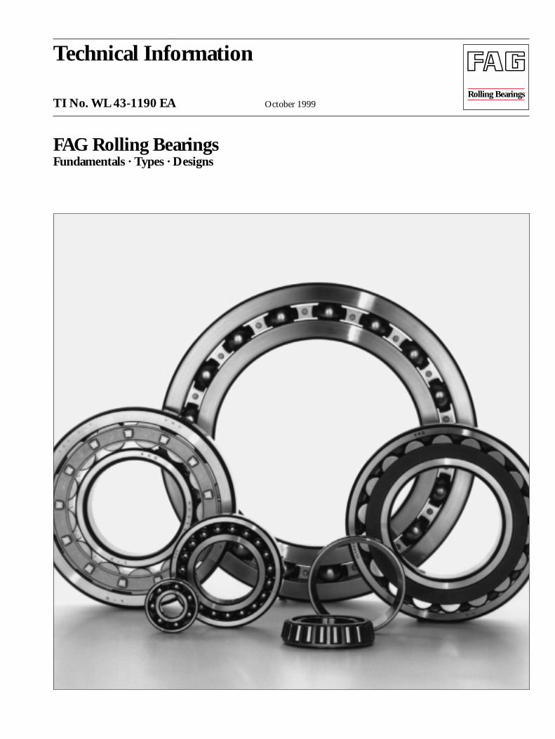
FAG Rolling BearingsFundamentals · Types · Designs
FAG 2
Contents · Introduction
Contents
The FAG rolling bearing programme . . . . . . . . . . . . . . . 3Rolling bearing types . . . . . . . . . . . . . . . . . . . . . . . . . . . . 4Rolling bearing components . . . . . . . . . . . . . . . . . . . . . . 5
Rolling elements . . . . . . . . . . . . . . . . . . . . . . . . . . 5Bearing rings . . . . . . . . . . . . . . . . . . . . . . . . . . . . . 6Cages . . . . . . . . . . . . . . . . . . . . . . . . . . . . . . . . . . . 6
Load ratings . . . . . . . . . . . . . . . . . . . . . . . . . . . . . . . . . . . 8Combined load . . . . . . . . . . . . . . . . . . . . . . . . . . . . . . . . . 8Dimensioning . . . . . . . . . . . . . . . . . . . . . . . . . . . . . . . . . . 9
Statically stressed bearings . . . . . . . . . . . . . . . . . . 9Service life . . . . . . . . . . . . . . . . . . . . . . . . . . . . . . . 9Wear . . . . . . . . . . . . . . . . . . . . . . . . . . . . . . . . . . . 9Dynamically stressed bearings . . . . . . . . . . . . . . . 10Nominal rating life . . . . . . . . . . . . . . . . . . . . . . . . 11Adjusted rating life calculation . . . . . . . . . . . . . . . 12
Lubrication . . . . . . . . . . . . . . . . . . . . . . . . . . . . . . . . . . . . 17Grease lubrication . . . . . . . . . . . . . . . . . . . . . . . . . 17Oil lubrication . . . . . . . . . . . . . . . . . . . . . . . . . . . 17Important rolling bearing lubrication terms . . . . 17
Seals . . . . . . . . . . . . . . . . . . . . . . . . . . . . . . . . . . . . . . . . . 21Speed suitability . . . . . . . . . . . . . . . . . . . . . . . . . . . . . . . . 22High temperature suitability . . . . . . . . . . . . . . . . . . . . . . 23Bearing clearance . . . . . . . . . . . . . . . . . . . . . . . . . . . . . . . 24Tolerances . . . . . . . . . . . . . . . . . . . . . . . . . . . . . . . . . . . . . 26Alignment . . . . . . . . . . . . . . . . . . . . . . . . . . . . . . . . . . . . . 27Fits . . . . . . . . . . . . . . . . . . . . . . . . . . . . . . . . . . . . . . . . . . 28Bearing arrangement . . . . . . . . . . . . . . . . . . . . . . . . . . . . 29Symbols for load carrying capacity, alignment
and speed suitability . . . . . . . . . . . . . . . . . . . . . . . 32Deep groove ball bearings . . . . . . . . . . . . . . . . . . . . . . . . 33Angular contact ball bearings, single row . . . . . . . . . . . . . 34Angular contact ball bearings, double row . . . . . . . . . . . . 35Four-point bearings . . . . . . . . . . . . . . . . . . . . . . . . . . . . . 36Self-aligning ball bearings . . . . . . . . . . . . . . . . . . . . . . . . 37Cylindrical roller bearings . . . . . . . . . . . . . . . . . . . . . . . . 38Tapered roller bearings . . . . . . . . . . . . . . . . . . . . . . . . . . . 40Barrel roller bearings . . . . . . . . . . . . . . . . . . . . . . . . . . . . 42Spherical roller bearings . . . . . . . . . . . . . . . . . . . . . . . . . . 43Thrust ball bearings . . . . . . . . . . . . . . . . . . . . . . . . . . . . . 45Angular contact thrust ball bearings . . . . . . . . . . . . . . . . 46Cylindrical roller thrust bearings . . . . . . . . . . . . . . . . . . . 47Spherical roller thrust bearings . . . . . . . . . . . . . . . . . . . . . 48Matched rolling bearings . . . . . . . . . . . . . . . . . . . . . . . . . 49Bearing units . . . . . . . . . . . . . . . . . . . . . . . . . . . . . . . . . . 50Checklist for rolling bearing determination . . . . . . . . . . 52Index . . . . . . . . . . . . . . . . . . . . . . . . . . . . . . . . . . . . . . . . . 53
Introduction
This Technical Information contains a summary of funda-mental knowledge of FAG rolling bearings and should serve asan introduction to rolling bearing engineering. It is intendedfor those who have little or no knowledge of rolling bearings.
If you should like to enlarge your fundamental knowledge atyour PC, we recommend you to use our rolling bearing learn-ing system W.L.S. (cp. also Publ. No. WL 00106).
The FAG catalogue WL 41520 "FAG Rolling Bearings" is frequently referred to in this publication. It provides all the essential data designers need to safely and economically designall standard rolling bearings.
The FAG rolling bearing catalogue on CD-ROM outshinesthe usual software catalogues, being a comfortable, electronicconsulting system. In a dialogue with WINDOWS you canquickly select the right FAG rolling bearing for your applica-tion and accurately calculate its life, speed, friction, tempera-ture and cycling frequencies. This will save you a lot of moneyand time.
A large number of technical publications is available for spe-cific applications which you can order from us indicating thepublication number.
Rolling bearing codes are explained in detail in our TechnicalInformation WL 43-1191.
Key rolling bearing engineering terms appear in boldface andwill be explained in more detail (see also index at the end ofthis TI).
3 FAG
The FAG rolling bearing programme
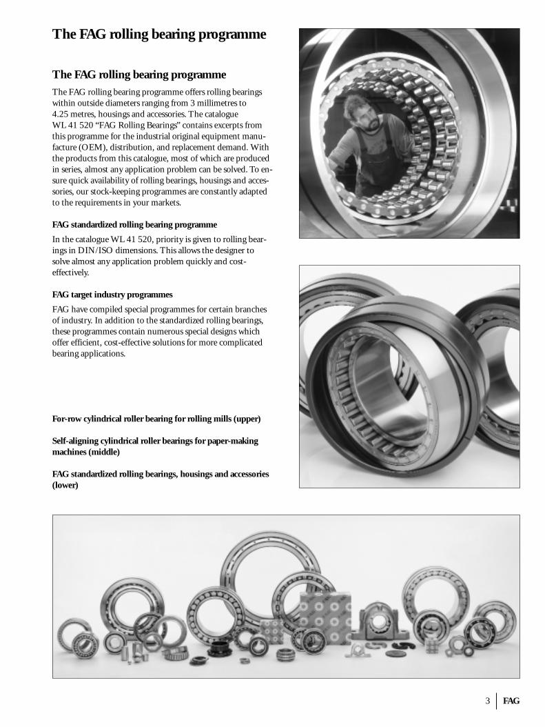
The FAG rolling bearing programmeThe FAG rolling bearing programme offers rolling bearingswithin outside diameters ranging from 3 millimetres to 4.25 metres, housings and accessories. The catalogue WL 41 520 “FAG Rolling Bearings” contains excerpts fromthis programme for the industrial original equipment manu-facture (OEM), distribution, and replacement demand. Withthe products from this catalogue, most of which are producedin series, almost any application problem can be solved. To en-sure quick availability of rolling bearings, housings and acces-sories, our stock-keeping programmes are constantly adaptedto the requirements in your markets.
FAG standardized rolling bearing programme
In the catalogue WL 41 520, priority is given to rolling bear-ings in DIN/ISO dimensions. This allows the designer to solve almost any application problem quickly and cost-effectively.
FAG target industry programmes
FAG have compiled special programmes for certain branchesof industry. In addition to the standardized rolling bearings,these programmes contain numerous special designs which offer efficient, cost-effective solutions for more complicatedbearing applications.
For-row cylindrical roller bearing for rolling mills (upper)
Self-aligning cylindrical roller bearings for paper-makingmachines (middle)
FAG standardized rolling bearings, housings and accessories(lower)
FAG 4
Rolling bearing types
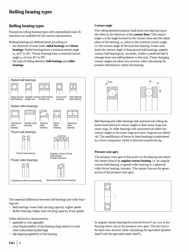
Rolling bearing typesNumerous rolling bearing types with standardized main di-mensions are available for the various requirements.
Rolling bearings are differentiated according to:– the direction of main load: radial bearings and thrust
bearings. Radial bearings have a nominal contact angle�0 of 0° to 45°. Thrust bearings have a nominal contactangle �0 of over 45° to 90°.
– the type of rolling elements: ball bearings and roller bearings.
The essential differences between ball bearings and roller bear-ings are:– Ball bearings: lower load carrying capacity, higher speeds– Roller bearings: higher load carrying capacity, lower speeds
Other distinctive characteristics:– separable or non-separable– axial displaceability of the bearing rings relative to each
other (ideal floating bearings)– self-aligning capability of the bearing
Contact angle
The rolling elements transmit loads from one bearing ring tothe other in the direction of the contact lines. The contactangle � is the angle formed by the contact lines and the radialplane of the bearing. �0 refers to the nominal contact angle,i.e. the contact angle of the load-free bearing. Under axial loads the contact angle of deep groove ball bearings, angularcontact ball bearings etc. increases. Under a combined load itchanges from one rolling element to the next. These changingcontact angles are taken into account when calculating thepressure distribution within the bearing.
Ball bearings and roller bearings with symmetrical rolling ele-ments have identical contact angles at their inner rings andouter rings. In roller bearings with asymmetrical rollers thecontact angles at the inner rings and outer rings are not identi-cal. The equilibrium of forces in these bearings is maintainedby a force component which is directed towards the lip.
Pressure cone apex
The pressure cone apex is that point on the bearing axis wherethe contact lines of an angular contact bearing, i.e. an angularcontact ball bearing, a tapered roller bearing or a spherical roller thrust bearing, intersect. The contact lines are the gener-atrices of the pressure cone apex.
In angular contact bearings the external forces F act, not at thebearing centre, but at the pressure cone apex. This fact has tobe taken into account when calculating the equivalent dynamicload P and the equivalent static load P0.
Radial ball bearings
Radial roller bearings
Thrust ball bearings
Thrust roller bearings
Deep grooveball bearing
Angular contact ball bearingsingle row
Four-pointbearing
Self-aligningball bearingdouble row
Cylindricalrollerbearing
Needle rollerbearing
Taperedrollerbearing
Barrelrollerbearing
Sphericalrollerbearing
Thrust ball bearing Angular contact thrustball bearingdouble direction
Cylindrical roller thrust bearing Spherical roller thrust bearing
α α
5 FAG
Rolling bearing componentsRolling elements
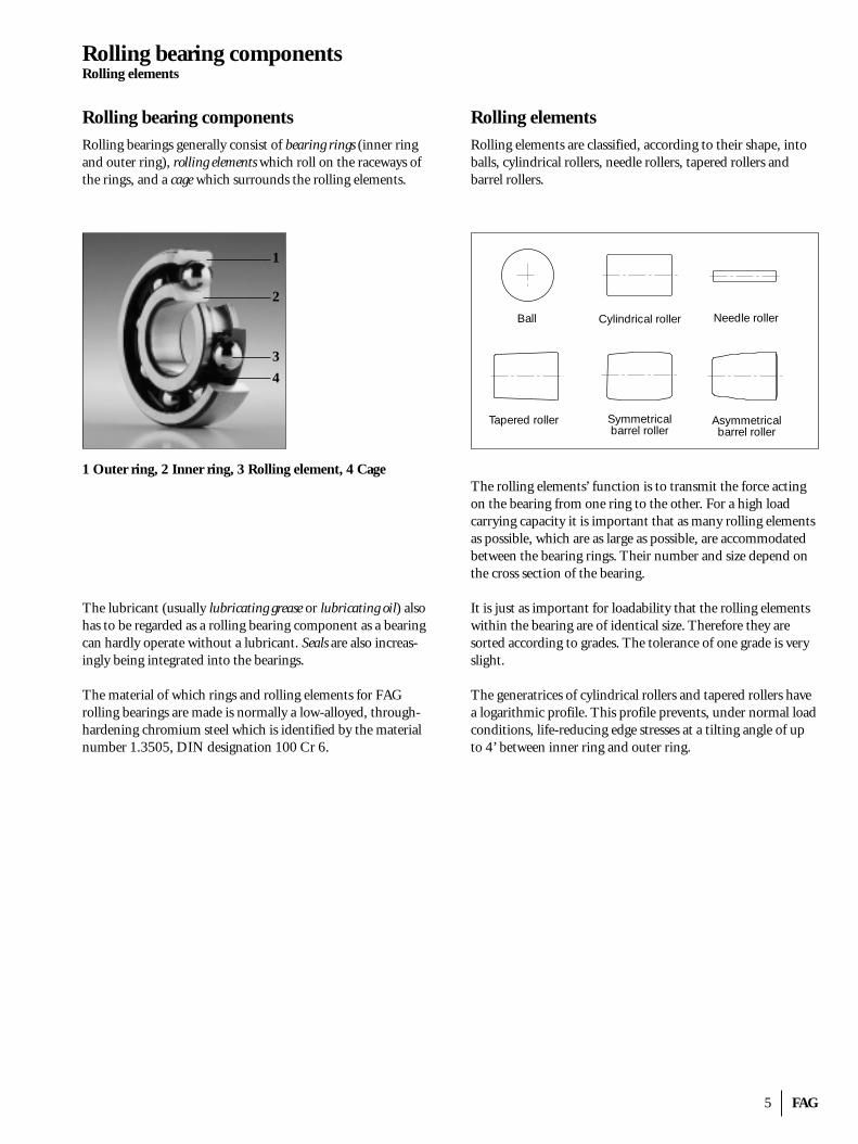
Rolling bearing componentsRolling bearings generally consist of bearing rings (inner ringand outer ring), rolling elements which roll on the raceways ofthe rings, and a cage which surrounds the rolling elements.
1 Outer ring, 2 Inner ring, 3 Rolling element, 4 Cage
The lubricant (usually lubricating grease or lubricating oil) alsohas to be regarded as a rolling bearing component as a bearingcan hardly operate without a lubricant. Seals are also increas-ingly being integrated into the bearings.
The material of which rings and rolling elements for FAG rolling bearings are made is normally a low-alloyed, through-hardening chromium steel which is identified by the materialnumber 1.3505, DIN designation 100 Cr 6.
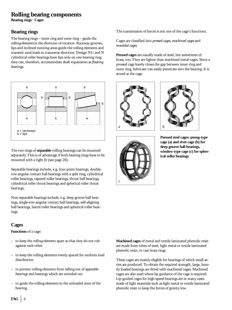
Rolling elementsRolling elements are classified, according to their shape, intoballs, cylindrical rollers, needle rollers, tapered rollers and barrel rollers.
The rolling elements’ function is to transmit the force actingon the bearing from one ring to the other. For a high loadcarrying capacity it is important that as many rolling elementsas possible, which are as large as possible, are accommodatedbetween the bearing rings. Their number and size depend onthe cross section of the bearing.
It is just as important for loadability that the rolling elementswithin the bearing are of identical size. Therefore they are sorted according to grades. The tolerance of one grade is veryslight.
The generatrices of cylindrical rollers and tapered rollers havea logarithmic profile. This profile prevents, under normal loadconditions, life-reducing edge stresses at a tilting angle of upto 4’ between inner ring and outer ring.
Ball Cylindrical roller Needle roller
Tapered roller Symmetricalbarrel roller
Asymmetricalbarrel roller
1
2
3
4
FAG 6
Rolling bearing componentsBearing rings · Cages
Bearing ringsThe bearing rings – inner ring and outer ring – guide the rolling elements in the direction of rotation. Raceway grooves,lips and inclined running areas guide the rolling elements andtransmit axial loads in transverse direction. Design NU and Ncylindrical roller bearings have lips only on one bearing ring;they can, therefore, accommodate shaft expansions as floatingbearings.
The two rings of separable rolling bearings can be mountedseparately. This is of advantage if both bearing rings have to bemounted with a tight fit (see page 28).
Separable bearings include, e.g. four-point bearings, double-row angular contact ball bearings with a split ring, cylindricalroller bearings, tapered roller bearings, thrust ball bearings, cylindrical roller thrust bearings and spherical roller thrustbearings.
Non-separable bearings include, e.g. deep groove ball bear-ings, single-row angular contact ball bearings, self-aligningball bearings, barrel roller bearings and spherical roller bear-ings.
CagesFunctions of a cage:
– to keep the rolling elements apart so that they do not rubagainst each other
– to keep the rolling elements evenly spaced for uniform loaddistribution
– to prevent rolling elements from falling out of separablebearings and bearings which are swiveled out
– to guide the rolling elements in the unloaded zone of thebearing.
The transmission of forces is not one of the cage's functions.
Cages are classified into pressed cages, machined cages and moulded cages.
Pressed cages are usually made of steel, but sometimes ofbrass, too. They are lighter than machined metal cages. Since apressed cage barely closes the gap between inner ring and outer ring, lubricant can easily penetrate into the bearing. It isstored at the cage.
Pressed steel cages: prong-typecage (a) and rivet cage (b) fordeep groove ball bearings, window-type cage (c) for spher-ical roller bearings
Machined cages of metal and textile laminated phenolic resinare made from tubes of steel, light metal or textile laminatedphenolic resin, or cast brass rings.
These cages are mainly eligible for bearings of which small se-ries are produced. To obtain the required strength, large, heav-ily loaded bearings are fitted with machined cages. Machinedcages are also used where lip guidance of the cage is required.Lip-guided cages for high-speed bearings are in many casesmade of light materials such as light metal or textile laminatedphenolic resin to keep the forces of gravity low.
a
a
a
a
a
a
b b
b
a = racewaysb = lips
a b
c
7 FAG
Rolling bearing componentsCages
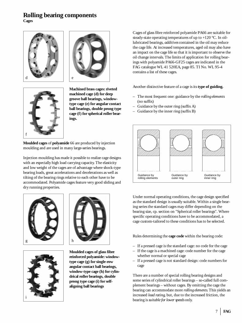
Machined brass cages: rivetedmachined cage (d) for deepgroove ball bearings, window-type cage (e) for angular contactball bearings, double prong typecage (f) for spherical roller bear-ings.
Moulded cages of polyamide 66 are produced by injectionmoulding and are used in many large-series bearings.
Injection moulding has made it possible to realize cage designswith an especially high load carrying capacity. The elasticityand low weight of the cages are of advantage where shock-typebearing loads, great accelerations and decelerations as well astilting of the bearing rings relative to each other have to be accommodated. Polyamide cages feature very good sliding anddry running properties.
Moulded cages of glass fibrereinforced polyamide: window-type cage (g) for single-row angular contact ball bearings,window-type cage (h) for cylin-drical roller bearings, doubleprong type cage (i) for self-aligning ball bearings
Cages of glass fibre reinforced polyamide PA66 are suitable forsteady-state operating temperatures of up to +120 °C. In oil-lubricated bearings, additives contained in the oil may reducethe cage life. At increased temperatures, aged oil may also havean impact on the cage life so that it is important to observe theoil change intervals. The limits of application for rolling bear-ings with polyamide PA66-GF25 cages are indicated in theFAG catalogue WL 41 520EA, page 85. TI No. WL 95-4 contains a list of these cages.
Another distinctive feature of a cage is its type of guiding.
– The most frequent one: guidance by the rolling elements(no suffix)
– Guidance by the outer ring (suffix A)– Guidance by the inner ring (suffix B)
Under normal operating conditions, the cage design specifiedas the standard design is usually suitable. Within a single bear-ing series the standard cages may differ depending on thebearing size, cp. section on "Spherical roller bearings". Wherespecific operating conditions have to be accommodated, acage custom-tailored to these conditions has to be selected.
Rules determining the cage code within the bearing code:
– If a pressed cage is the standard cage: no code for the cage– If the cage is a machined cage: code number for the cage
whether normal or special cage– If a pressed cage is not standard design: code numbers for
cage
There are a number of special rolling bearing designs andsome series of cylindrical roller bearings – so-called full com-plement bearings – without cages. By omitting the cage thebearing can accommodate more rolling elements. This yields anincreased load rating, but, due to the increased friction, thebearing is suitable for lower speeds only.
d e
g
i
h
Guidance byrolling elements
Guidance byouter ring
Guidance byinner ring
f
FAG 8
Load ratings · Combined load
Load ratingsThe load rating of a bearing reflects its load carrying capacityand is an important factor in the dimensioning of rolling bear-ings. It is determined by the number and size of the rolling elements, the curvature ratio, the contact angle and the pitchcircle diameter of the bearing. Due to the larger contact areabetween rollers and raceways the load ratings of roller bearingsare higher than those of ball bearings.
The load rating of a radial bearing is defined for radial loadswhereas that of a thrust bearing is defined for axial loads. Everyrolling bearing has a dynamic load rating and a static load rat-ing. The terms "dynamic" and "static" refer to the movementof the bearing but not to the type of load.
In all rolling bearings with a curved raceway profile the radiusof the raceway is slightly larger than that of the rolling ele-ments. This curvature difference in the axial plane is definedby the curvature ratio �. The curvature ratio is the curvaturedifference between the rolling element radius and the slightlylarger groove radius.
curvature ratio � = groove radius – rolling element radius
rolling element radius
Dynamic load rating
Load rating comparison of a few rolling bearing types with abore diameter of d = 25 mm
Rolling bearing Dyn. loadrating CkN
Deep groove ball bearing 6205 14Cylindrical roller bearing NU205E 29Tapered roller bearing 30205A 32.5Spherical roller bearing 22205E 43
The dynamic load rating C is a factor for the load carrying capacity of a rolling bearing under dynamic load at which thebearing rings rotate relative to each other. It is defined as theload, constant in magnitude and direction, a rolling bearingcan theoretically accommodate for a nominal rating life of 1 million revolutions (DIN ISO 281).
Static load rating
In statically stressed bearings there is no relative motion between the bearing rings or only a very slow one. A loadequalling the static load rating C0 in magnitude generates inthe middle of the rolling element /raceway contact area, whichis the most heavily loaded, a Hertzian contact pressure of approximately
4600 N/mm2 in self-aligning ball bearings,4200 N/mm2 in all other ball bearings,4000 N/mm2 in all roller bearings
Under the C0 load a total plastic deformation of rolling ele-ment and raceway of about 0.01% of the rolling elementdiameter at the most heavily loaded contact area arises (DINISO 76).
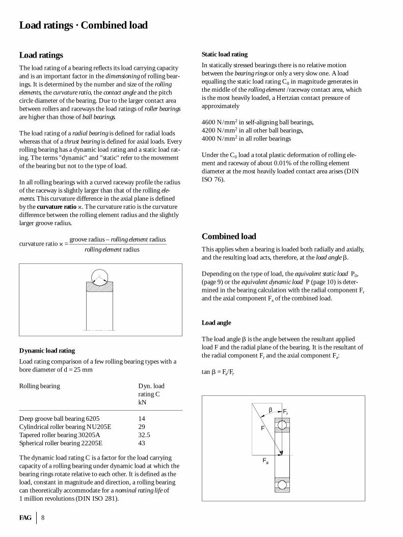
Combined loadThis applies when a bearing is loaded both radially and axially,and the resulting load acts, therefore, at the load angle �.
Depending on the type of load, the equivalent static load P0,(page 9) or the equivalent dynamic load P (page 10) is deter-mined in the bearing calculation with the radial component Fr
and the axial component Fa of the combined load.
Load angle
The load angle � is the angle between the resultant appliedload F and the radial plane of the bearing. It is the resultant ofthe radial component Fr and the axial component Fa:
tan � = Fa/Fr
β
F
Fr
Fa
9 FAG
DimensioningStatically stressed bearings · Service life · Wear
DimensioningA dimension calculation is carried out to check whether re-quirements on life, static safety and cost efficiency of a bearinghave been fulfilled. This calculation involves the comparisonof a bearing's load with its load carrying capacity. In rollingbearing engineering a differentiation is made between dynamicand static stress.
The dimensions calculation is considerably facilitated by theelectronic FAG rolling bearing catalogue on CD-ROM, cp.also “Introduction” on page 2.
Statically stressed rolling bearingsStatic stress refers to bearings carrying a load when stationary(no relative movement between the bearing rings). The term"static", therefore, relates to the operation of the bearing butnot to the effects of the load. The magnitude and direction ofload may change.
Bearings which perform slow slewing motions or rotate at alow speed (n < 10 min–1) are calculated like statically stressedbearings (cp. dynamically stressed rolling bearings, page 10).
For static stress conditions the safety against excessive plasticdeformations of the raceways and rolling elements is checked.
Equivalent static load P0
Statically stressed rolling bearings which operate under a com-bined load are calculated with the equivalent static load. It is aradial load for radial bearings and an axial load for thrust bear-ings, having the same effect with regard to permanent defor-mation as the combined load. The equivalent static load P0 iscalculated with the formula:
P0 = X0 · Fr + Y0 · Fa
Fr radial loadFa axial loadX0 radial factor (see FAG catalogues)Y0 axial factor (see FAG catalogues)
Index of static stressing fs
The index of static stressing fs for statically loaded bearings iscalculated to ensure that an adequately dimensioned bearinghas been selected. It is calculated from the static load rating C0
(see page 8) and the equivalent static load P0.
fs = C0
P0
The index fs is a safety factor against excessively great total plastic deformation in the contact area of the raceway and themost highly loaded rolling element.
A high fs value is necessary for bearings which must run smoothly and particularly quietly. Smaller values satisfy modest demands on the quietness of running. Commonly applicable values are:
fs = 1.5...2.5 for high demandsfs = 1...1.2 for normal demandsfs = 0.7...1 for modest demands
Service lifeThis is the life during which the bearing operates reliably.
The fatigue life of a bearing (cp. section on "Bearing life", page 10) is the upper limit of the service life. Often this limitis not reached due to wear or lubrication breakdown.
WearThe life of rolling bearings can be terminated, apart from fatigue, as a result of wear. The clearance of a worn bearinggets too large.
One frequent cause of wear are foreign particles which pene-trate into a bearing due to insufficient sealing and have anabrasive effect. Wear is also caused by starved lubrication andwhen the lubricant is used up.
Therefore, wear can be considerably reduced by providinggood lubrication conditions (viscosity ratio � > 2 if possible)and a good degree of cleanliness in the rolling bearing. Where� ≤ 0.4 wear will dominate in the bearing if it is not preventedby suitable additives (EP additives).
FAG 10
DimensioningDynamically stressed bearings · Bearing life
Dynamically stressed rolling bearingsRolling bearings are dynamically stressed when one ring ro-tates relative to the other under load. The term "dynamic"does not refer, therefore, to the effect of the load but rather tothe operating condition of the bearing. The magnitude anddirection of the load can remain constant.
When calculating the bearings, a dynamic stress is assumedwhen the speed n amounts to at least 10 min–1 (see static stressing).
Equialent dynamic load P
For dynamically loaded rolling bearings operating under com-bined load, the calculation is based on the equivalent dynamicload. This is a radial load for radial bearings and an axial andcentrical load for axial bearings, having the same effect on fatigue as the combined load. The equivalent dynamic load P iscalculated by means of the following equation:
P = X · Fr + Y · Fa
Fr radial loadFa axial loadX radial factorY axial factor
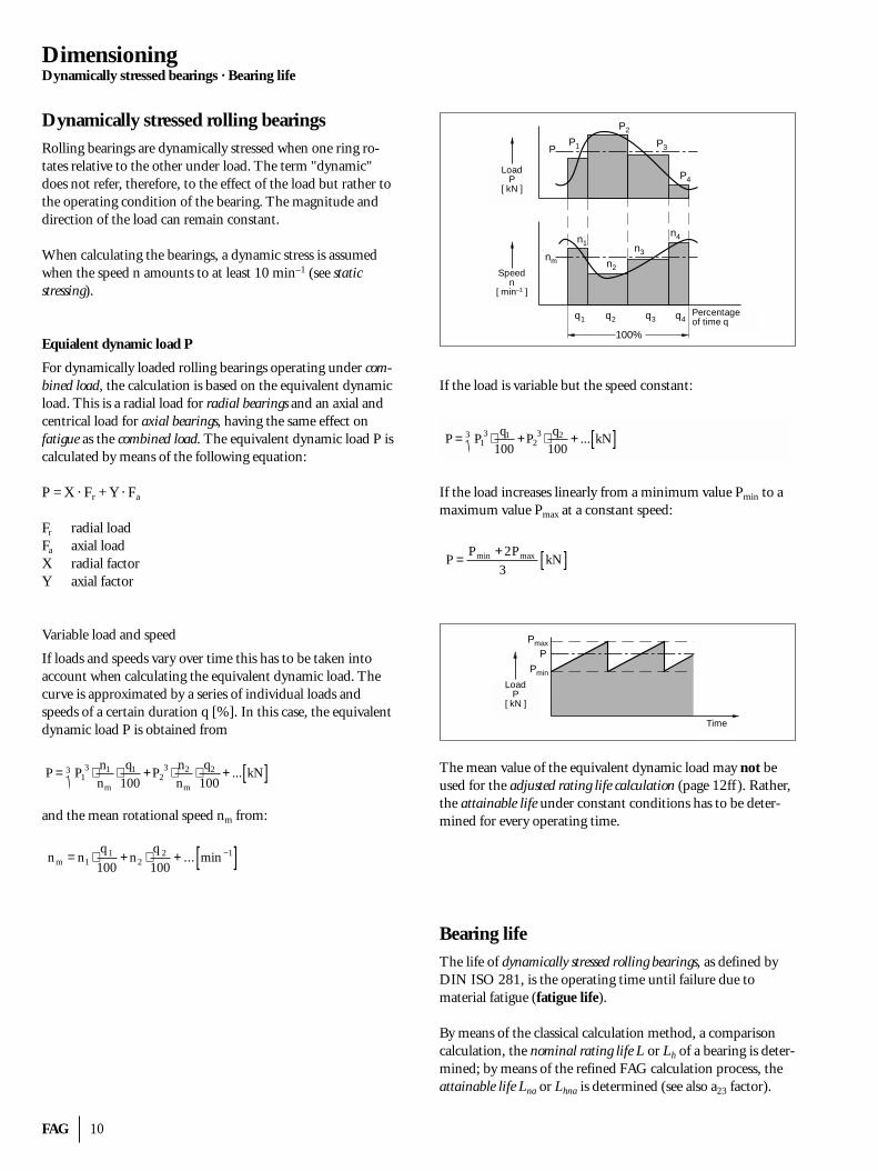
Variable load and speed
If loads and speeds vary over time this has to be taken into account when calculating the equivalent dynamic load. Thecurve is approximated by a series of individual loads andspeeds of a certain duration q [%]. In this case, the equivalentdynamic load P is obtained from
and the mean rotational speed nm from:
nm = n1 ⋅
q 1
100+n2 ⋅
q 2
100+ ... min −1[ ]
P = P1
3 ⋅ n1
nm
⋅ q1
100+P2
3 ⋅ n2
nm
⋅ q2
100+ ...3 kN[ ]
If the load is variable but the speed constant:
If the load increases linearly from a minimum value Pmin to amaximum value Pmax at a constant speed:
The mean value of the equivalent dynamic load may not beused for the adjusted rating life calculation (page 12ff ). Rather,the attainable life under constant conditions has to be deter-mined for every operating time.
Bearing lifeThe life of dynamically stressed rolling bearings, as defined byDIN ISO 281, is the operating time until failure due to material fatigue (fatigue life).
By means of the classical calculation method, a comparisoncalculation, the nominal rating life L or Lh of a bearing is deter-mined; by means of the refined FAG calculation process, theattainable life Lna or Lhna is determined (see also a23 factor).
P = Pmin +2Pmax
3kN[ ]
P = P1
3 ⋅ q1
100+P2
3 ⋅ q2
100+ ...3 kN[ ]
PP1
P2
P3
P4
n4
n3
n2
n1
nm
q1 q2 q3 q4
100%
Belastung
Drehzahl
Zeitanteil q
P
n
[ kN ]
[ min-1 ]
PPmax
Pmin
Belastung
Zeit
P[ kN ]
Speedn
[ min–1 ]
LoadP
[ kN ]
Percentageof time q
LoadP
[ kN ]
Time
11 FAG
DimensioningDynamically stressed bearings · Nominal rating life
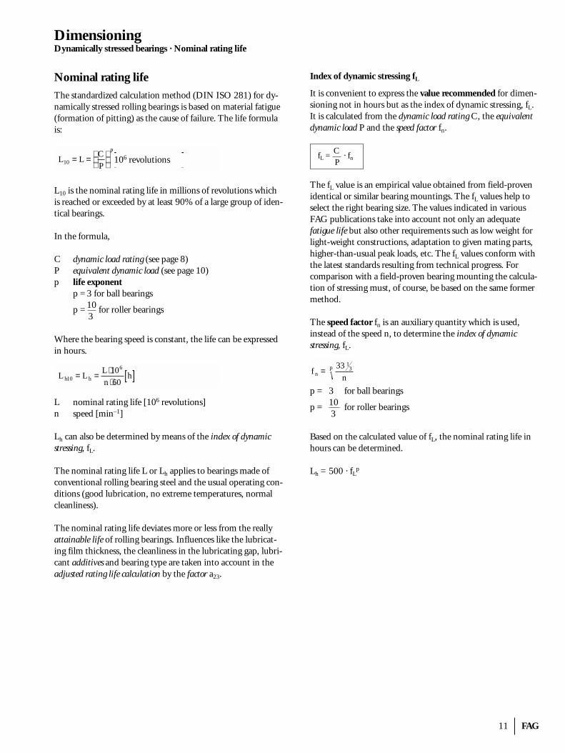
Nominal rating lifeThe standardized calculation method (DIN ISO 281) for dy-namically stressed rolling bearings is based on material fatigue(formation of pitting) as the cause of failure. The life formulais:
L10 is the nominal rating life in millions of revolutions whichis reached or exceeded by at least 90% of a large group of iden-tical bearings.
In the formula,
C dynamic load rating (see page 8)P equivalent dynamic load (see page 10)p life exponent
p = 3 for ball bearings
p = 10 for roller bearings 3
Where the bearing speed is constant, the life can be expressedin hours.
L nominal rating life [106 revolutions]n speed [min–1]
Lh can also be determined by means of the index of dynamicstressing, fL.
The nominal rating life L or Lh applies to bearings made ofconventional rolling bearing steel and the usual operating con-ditions (good lubrication, no extreme temperatures, normalcleanliness).
The nominal rating life deviates more or less from the reallyattainable life of rolling bearings. Influences like the lubricat-ing film thickness, the cleanliness in the lubricating gap, lubri-cant additives and bearing type are taken into account in theadjusted rating life calculation by the factor a23.
L h10 = L h = L ⋅106
n ⋅60h[ ]
L10 = L = C
P
p
106 Umdrehungen[ ]
Index of dynamic stressing fL
It is convenient to express the value recommended for dimen-sioning not in hours but as the index of dynamic stressing, fL.It is calculated from the dynamic load rating C, the equivalentdynamic load P and the speed factor fn.
fL = C · fnP
The fL value is an empirical value obtained from field-provenidentical or similar bearing mountings. The fL values help toselect the right bearing size. The values indicated in variousFAG publications take into account not only an adequate fatigue life but also other requirements such as low weight forlight-weight constructions, adaptation to given mating parts,higher-than-usual peak loads, etc. The fL values conform withthe latest standards resulting from technical progress. Forcomparison with a field-proven bearing mounting the calcula-tion of stressing must, of course, be based on the same formermethod.
The speed factor fn is an auxiliary quantity which is used, instead of the speed n, to determine the index of dynamic stressing, fL.
p = 3 for ball bearings
p = 10 for roller bearings 3
Based on the calculated value of fL, the nominal rating life inhours can be determined.
Lh = 500 · fLp
f n = 33 13
np
106 revolutions
FAG 12
DimensioningDynamically stressed bearings · Adjusted rating life calculation
Adjusted rating life calculationThe nominal rating life L or Lh deviates more or less from thereally attainable life of rolling bearings.
Therefore, additional important operating conditions besidesthe load have to be taken into account in the adjusted ratinglife calculation.
Modified life
The standard DIN ISO 281 introduced, in addition to the nominal rating life L10, the modified life Lna to take into account, apart from the load, the influence of the failure prob-ability (factor a1), of the material (factor a2) and of the oper-ating conditions (factor a3).
DIN ISO 281 indicates no figures for the factor a23
(a23 = a2 . a3). With the FAG calculation process for the attain-able life (Lna, Lhna), however, operating conditions can be ex-pressed in terms of figures by the factor a23.
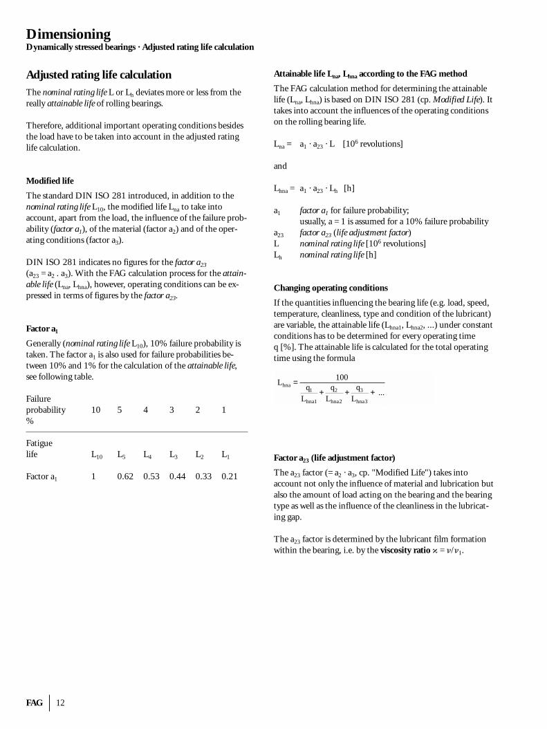
Factor a1
Generally (nominal rating life L10), 10% failure probability istaken. The factor a1 is also used for failure probabilities be-tween 10% and 1% for the calculation of the attainable life,see following table.
Failureprobability 10 5 4 3 2 1%
Fatiguelife L10 L5 L4 L3 L2 L1
Factor a1 1 0.62 0.53 0.44 0.33 0.21
Attainable life Lna, Lhna according to the FAG method
The FAG calculation method for determining the attainablelife (Lna, Lhna) is based on DIN ISO 281 (cp. Modified Life). Ittakes into account the influences of the operating conditionson the rolling bearing life.
Lna = a1 · a23 · L [106 revolutions]
and
Lhna = a1 · a23 · Lh [h]
a1 factor a1 for failure probability;usually, a = 1 is assumed for a 10% failure probability
a23 factor a23 (life adjustment factor)L nominal rating life [106 revolutions]Lh nominal rating life [h]
Changing operating conditions
If the quantities influencing the bearing life (e.g. load, speed,temperature, cleanliness, type and condition of the lubricant)are variable, the attainable life (Lhna1, Lhna2, ...) under constantconditions has to be determined for every operating time q [%]. The attainable life is calculated for the total operatingtime using the formula
Factor a23 (life adjustment factor)
The a23 factor (= a2 · a3, cp. "Modified Life") takes into account not only the influence of material and lubrication butalso the amount of load acting on the bearing and the bearingtype as well as the influence of the cleanliness in the lubricat-ing gap.
The a23 factor is determined by the lubricant film formationwithin the bearing, i.e. by the viscosity ratio � = �/�1.
Lhna = 100q1
Lhna1
+ q2
Lhna2
+ q3
Lhna3
+ ...
13 FAG
DimensioningDynamically stressed bearings · Adjusted rating life calculation
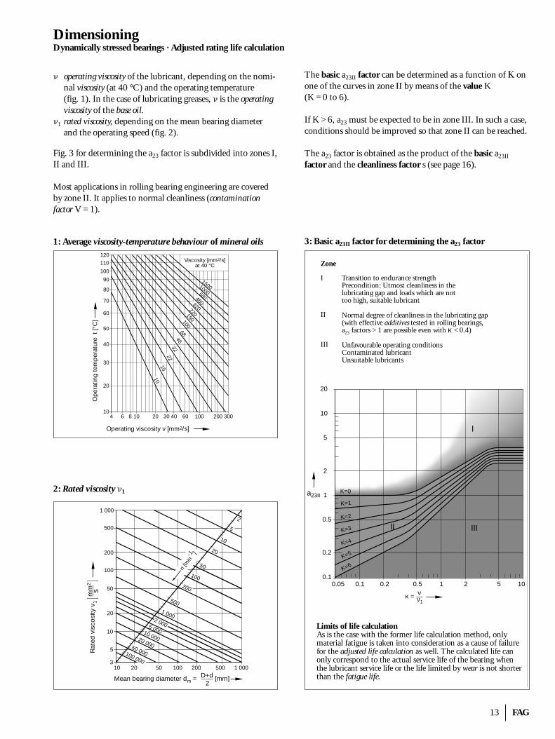
� operating viscosity of the lubricant, depending on the nomi-nal viscosity (at 40 °C) and the operating temperature (fig. 1). In the case of lubricating greases, � is the operatingviscosity of the base oil.
�1 rated viscosity, depending on the mean bearing diameterand the operating speed (fig. 2).
Fig. 3 for determining the a23 factor is subdivided into zones I,II and III.
Most applications in rolling bearing engineering are coveredby zone II. It applies to normal cleanliness (contamination factor V = 1).
1: Average viscosity-temperature behaviour of mineral oils
2: Rated viscosity �1
The basic a23II factor can be determined as a function of � onone of the curves in zone II by means of the value K (K = 0 to 6).
If K > 6, a23 must be expected to be in zone III. In such a case,conditions should be improved so that zone II can be reached.
The a23 factor is obtained as the product of the basic a23II
factor and the cleanliness factor s (see page 16).
3: Basic a23II factor for determining the a23 factor
Mean bearing diameter dm = D+d2
[mm]
n [m
in-1 ]
100 000
50 000
20 000
10 000
5 000
2 000
1 000
500
200
100
50
20
10
5
21 000
500
200
100
50
20
10
5
310 20 50 100 200 500 1 000
Rat
ed v
isco
sity
ν1
mm
2
s
1500100068046032022015010068
4632
22
15
10
120
110
100
90
80
70
60
50
40
30
20
104 6 8 10 20 30 40 60 100 200 300
Viscosity [mm2/s]at 40 °C
Op
erat
ing
tem
per
atur
e t
[°C
]
Operating viscosity ν [mm2/s]
Limits of life calculationAs is the case with the former life calculation method, onlymaterial fatigue is taken into consideration as a cause of failurefor the adjusted life calculation as well. The calculated life canonly correspond to the actual service life of the bearing whenthe lubricant service life or the life limited by wear is not shorterthan the fatigue life.
κ = ν1
ν
a23II
20
10
5
2
1
0.5
0.2
0.10.05 0.1 0.2 0.5 1 2 5 10
K=0
K=1
K=2
K=3
K=4
K=5
K=6
I
II III
Transition to endurance strengthPrecondition: Utmost cleanliness in thelubricating gap and loads which are nottoo high, suitable lubricant
Normal degree of cleanliness in the lubricating gap(with effective additives tested in rolling bearings,a23 factors > 1 are possible even with κ < 0.4)
Unfavourable operating conditionsContaminated lubricantUnsuitable lubricants
Zone
I
II
III
FAG 14
DimensioningDynamically stressed bearings · Adjusted rating life calculation
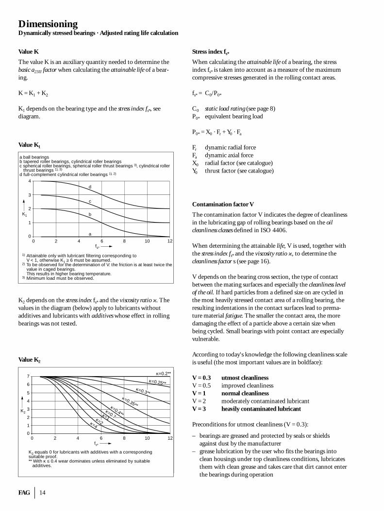
Value K
The value K is an auxiliary quantity needed to determine thebasic a23II factor when calculating the attainable life of a bear-ing.
K = K1 + K2
K1 depends on the bearing type and the stress index fs*, see diagram.
Value K1
K2 depends on the stress index fs* and the viscosity ratio �. The values in the diagram (below) apply to lubricants without additives and lubricants with additives whose effect in rollingbearings was not tested.
Value K2
Stress index fs*
When calculating the attainable life of a bearing, the stress index fs* is taken into account as a measure of the maximumcompressive stresses generated in the rolling contact areas.
fs* = C0/P0*
C0 static load rating (see page 8)P0* equivalent bearing load
P0* = X0 · Fr + Y0 · Fa
Fr dynamic radial forceFa dynamic axial forceX0 radial factor (see catalogue)Y0 thrust factor (see catalogue)
Contamination factor V
The contamination factor V indicates the degree of cleanlinessin the lubricating gap of rolling bearings based on the oil cleanliness classes defined in ISO 4406.
When determining the attainable life, V is used, together withthe stress index fs* and the viscosity ratio �, to determine the cleanliness factor s (see page 16).
V depends on the bearing cross section, the type of contactbetween the mating surfaces and especially the cleanliness levelof the oil. If hard particles from a defined size on are cycled inthe most heavily stressed contact area of a rolling bearing, theresulting indentations in the contact surfaces lead to prema-ture material fatigue. The smaller the contact area, the more damaging the effect of a particle above a certain size whenbeing cycled. Small bearings with point contact are especiallyvulnerable.
According to today's knowledge the following cleanliness scaleis useful (the most important values are in boldface):
V = 0.3 utmost cleanlinessV = 0.5 improved cleanlinessV = 1 normal cleanlinessV = 2 moderately contaminated lubricantV = 3 heavily contaminated lubricant
Preconditions for utmost cleanliness (V = 0.3):
– bearings are greased and protected by seals or shieldsagainst dust by the manufacturer
– grease lubrication by the user who fits the bearings into clean housings under top cleanliness conditions, lubricatesthem with clean grease and takes care that dirt cannot enterthe bearings during operation
a ball bearingsb tapered roller bearings, cylindrical roller bearingsc spherical roller bearings, spherical roller thrust bearings 3), cylindrical roller thrust bearings 1), 3)
d full-complement cylindrical roller bearings 1), 2)
1) Attainable only with lubricant filtering corresponding to V < 1, otherwise K1 ≥ 6 must be assumed.2) To be observed for the determination of V: the friction is at least twice the value in caged bearings. This results in higher bearing temperature.3) Minimum load must be observed.
4
3
2
1
00 2 4 6 8 10 12
a
K1
fs*
b
c
d
7
6
5
4
3
2
1
00 2 4 6 8 10 12
fs*
K2
κ=0.25**κ=0.3**
κ=0.35**κ=0.4**κ=0.7κ=1κ=2κ=4
κ=0.2**
K2 equals 0 for lubricants with additives with a correspondingsuitable proof.** With κ ≤ 0.4 wear dominates unless eliminated by suitable additives.
15 FAG
DimensioningDynamically stressed bearings · Adjusted rating life calculation
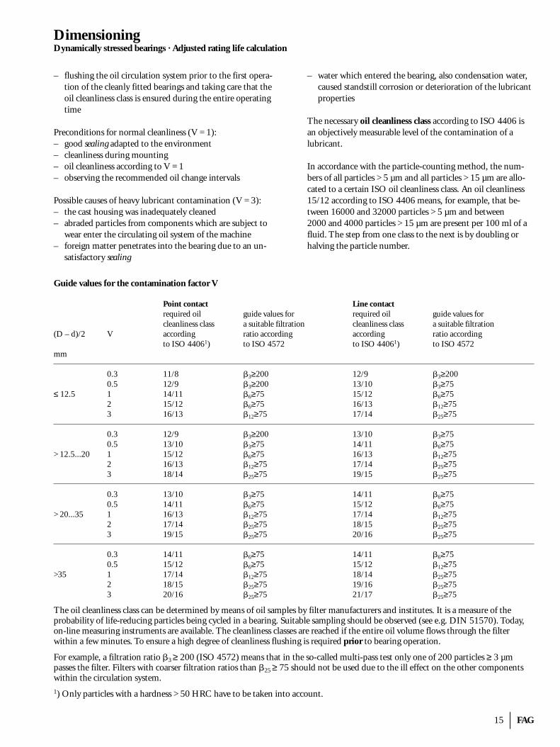
– flushing the oil circulation system prior to the first opera-tion of the cleanly fitted bearings and taking care that theoil cleanliness class is ensured during the entire operatingtime
Preconditions for normal cleanliness (V = 1):– good sealing adapted to the environment– cleanliness during mounting– oil cleanliness according to V = 1– observing the recommended oil change intervals
Possible causes of heavy lubricant contamination (V = 3):– the cast housing was inadequately cleaned– abraded particles from components which are subject to
wear enter the circulating oil system of the machine– foreign matter penetrates into the bearing due to an un-
satisfactory sealing
– water which entered the bearing, also condensation water,caused standstill corrosion or deterioration of the lubricantproperties
The necessary oil cleanliness class according to ISO 4406 isan objectively measurable level of the contamination of a lubricant.
In accordance with the particle-counting method, the num-bers of all particles > 5 µm and all particles > 15 µm are allo-cated to a certain ISO oil cleanliness class. An oil cleanliness15/12 according to ISO 4406 means, for example, that be-tween 16000 and 32000 particles > 5 µm and between 2000 and 4000 particles > 15 µm are present per 100 ml of afluid. The step from one class to the next is by doubling orhalving the particle number.
Guide values for the contamination factor V
Point contact Line contactrequired oil guide values for required oil guide values for cleanliness class a suitable filtration cleanliness class a suitable filtration
(D – d)/2 V according ratio according according ratio according to ISO 44061) to ISO 4572 to ISO 44061) to ISO 4572
mm
0.3 11/8 �3≥200 12/9 �3≥2000.5 12/9 �3≥200 13/10 �3≥75
≤ 12.5 1 14/11 �6≥75 15/12 �6≥752 15/12 �6≥75 16/13 �12≥753 16/13 �12≥75 17/14 �25≥75
0.3 12/9 �3≥200 13/10 �3≥750.5 13/10 �3≥75 14/11 �6≥75
> 12.5...20 1 15/12 �6≥75 16/13 �12≥752 16/13 �12≥75 17/14 �25≥753 18/14 �25≥75 19/15 �25≥75
0.3 13/10 �3≥75 14/11 �6≥750.5 14/11 �6≥75 15/12 �6≥75
> 20...35 1 16/13 �12≥75 17/14 �12≥752 17/14 �25≥75 18/15 �25≥753 19/15 �25≥75 20/16 �25≥75
0.3 14/11 �6≥75 14/11 �6≥750.5 15/12 �6≥75 15/12 �12≥75
>35 1 17/14 �12≥75 18/14 �25≥752 18/15 �25≥75 19/16 �25≥753 20/16 �25≥75 21/17 �25≥75
The oil cleanliness class can be determined by means of oil samples by filter manufacturers and institutes. It is a measure of the probability of life-reducing particles being cycled in a bearing. Suitable sampling should be observed (see e.g. DIN 51570). Today,on-line measuring instruments are available. The cleanliness classes are reached if the entire oil volume flows through the filter within a few minutes. To ensure a high degree of cleanliness flushing is required prior to bearing operation.
For example, a filtration ratio �3 ≥ 200 (ISO 4572) means that in the so-called multi-pass test only one of 200 particles ≥ 3 µm passes the filter. Filters with coarser filtration ratios than �25 ≥ 75 should not be used due to the ill effect on the other componentswithin the circulation system.1) Only particles with a hardness > 50 HRC have to be taken into account.
FAG 16
DimensioningDynamically stressed bearings · Adjusted rating life calculation
Specially particles with a hardness > 50 HRC reduce the life ofrolling bearings. These are particles of hardened steel, sandand abrasive particles. Abrasive particles are particularly harm-ful. If the major part of foreign particles in the oil samples is inthe life-reducing hardness range, which is the case in manytechnical applications, the cleanliness class determined with aparticle counter can be compared directly with the values ofthe table on page 15.If however, the filtered out contaminants are found, aftercounting, to be almost exclusively mineral matter as, for ex-ample, the particularly harmful moulding sand or abrasivegrains, the measured values must be increased by one or twocleanliness classes before determining the contamination fac-tor V. On the other hand, if the greater part of the particles found in the lubricant are soft materials such as wood, fibresor paint, the measured value of the particle counter should bereduced correspondingly.
A defined filtration ratio �x should exist in order to reach theoil cleanliness required. The filtration ratio is a measure of theseparation capability of a filter at defined particle sizes. Filtra-tion ratio �x is the ratio of all particles > x µm before passingthrough the filter to the particles > x µm which have passedthrough the filter.
A filter of a certain filtration ratio is not automatically indica-tive of an oil cleanliness class.
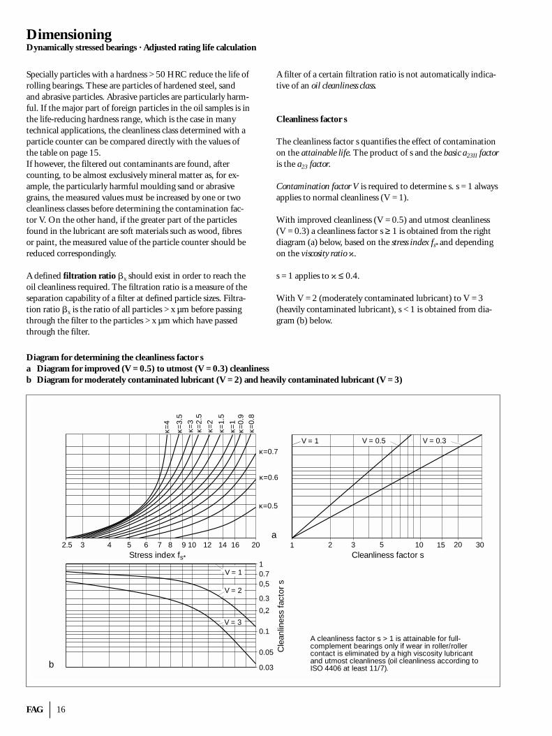
Cleanliness factor s
The cleanliness factor s quantifies the effect of contaminationon the attainable life. The product of s and the basic a23II factoris the a23 factor.
Contamination factor V is required to determine s. s = 1 alwaysapplies to normal cleanliness (V = 1).
With improved cleanliness (V = 0.5) and utmost cleanliness(V = 0.3) a cleanliness factor s ≥ 1 is obtained from the rightdiagram (a) below, based on the stress index fs* and dependingon the viscosity ratio �.
s = 1 applies to � ≤ 0.4.
With V = 2 (moderately contaminated lubricant) to V = 3(heavily contaminated lubricant), s < 1 is obtained from dia-gram (b) below.
Diagram for determining the cleanliness factor sa Diagram for improved (V = 0.5) to utmost (V = 0.3) cleanlinessb Diagram for moderately contaminated lubricant (V = 2) and heavily contaminated lubricant (V = 3)
1
V = 1
2.5 3 4 5 6 7 8 9 10 12 14 16 20 2 3 5 10 15 20 30
κ=1
κ=0.7
κ=0.5
1
V = 0.5 V = 0.3
κ=0.6
κ=0.
9κ=
0.8
κ=1.
5
κ=2
κ=2.
5κ=
3
κ=3.
5
κ=4
0.1
0,2
0.3
0.70,5
V = 1
V = 2
V = 3
0.05
0.03
a
b
Cleanliness factor sStress index fs*
Cle
anlin
ess
fact
or s
A cleanliness factor s > 1 is attainable for full-complement bearings only if wear in roller/rollercontact is eliminated by a high viscosity lubricantand utmost cleanliness (oil cleanliness according toISO 4406 at least 11/7).
17 FAG
LubricationGrease lubrication · Oil lubrication · Important rolling bearing lubrication terms
LubricationThe main objective of lubrication is to prevent metal-to-metalcontact between the bearing rings and the rolling elements bymeans of a lubricant film. In this way, wear and premature rolling bearing fatigue are avoided. In addition, lubrication re-duces the development of noise and friction, thus improvingthe operating characteristics of a bearing. Additional functionsmay include protection against corrosion and heat dissipationfrom the bearing.
Usually, bearings are lubricated with grease or oil; in rare cases,e.g. where very high temperatures are involved, dry lubricantsare also used.
Rolling bearing lubrication is discussed in detail in the FAGpublication No. WL 81115/4EA.
Grease lubricationGrease lubrication is used for about 90% of all rolling bear-ings. The main advantages of grease lubrication are:– a very simple design– it enhances the sealing effect– long service life but little maintenance is required
With normal operating and environmental conditions, for-lifegrease lubrication is often possible.
If a bearing is heavily stressed (load, speed, temperature), suit-able relubrication intervals must be scheduled.
Oil lubricationOil lubrication is the obvious solution for applications whereadjacent machine elements are already supplied with oil orwhere heat has to be removed by means of the lubricant.
Heat can be removed by circulating substantial oil volumes. Itmay be required where high loads and/or high speeds have tobe accommodated or where the bearings are exposed to exter-nal heating.
With oil throwaway lubrication, e.g. oil mist lubrication oroil-air lubrication, the bearing friction is kept low.
Important rolling bearing lubrication terms(in alphabetical order)Additives
Additives are oil soluble substances wich are added to mineraloils or mineral oil products. By chemical and/or physical action, they change or improve the lubricant properties (oxi-dation stability, EP properties, viscosity-temperature behaviour,setting point, flow property, etc.). Additives are also an impor-tant factor in calculating the attainable bearing life.
Ageing
is the undesirable chemical alteration of mineral and syntheticproducts (e.g. lubricants, fuels) during their application andstorage; triggered by reactions with oxygen (development ofperoxides, hydrocarbon radicals); heat, light as well as catalyticinfluences of metals and other contaminants accelerate oxida-tion. Formation of acids and sludge. Agents inhibiting deteri-oration (anti-oxidants) retard the deterioration process.
Arcanol (FAG rolling bearing greases)
FAG rolling bearing greases Arcanol are field-proven lubricat-ing greases whose application ranges were determined withbearings of all types under diverse operating conditions. A selection of the main Arcanol rolling bearing greases is shownin the table on page 18. It also contains directions for use.
Base oil
is the oil contained in a lubricating grease. The amount of oilvaries with the type of thickener and the grease application.The penetration number (see Consistency) and the frictionalbehaviour of the grease vary with the amount of base oil andits viscosity.
Consistency
A measure of the resistance of a lubricating grease to being de-formed. The so-called worked penetration at 25 °C is indicat-ed for the greases available on the market. There are several penetration classes (NLGI classes).
Dry lubricants
Substances, such as graphite and molybdenum disulphide,suspended in lubricating oils and greases or applied directly.
EP additives
Additives which reduce wear in lubricating oils and lubricatinggreases, also referred to as extreme pressure additives.
FAG 18
LubricationImportant rolling bearing lubrication terms
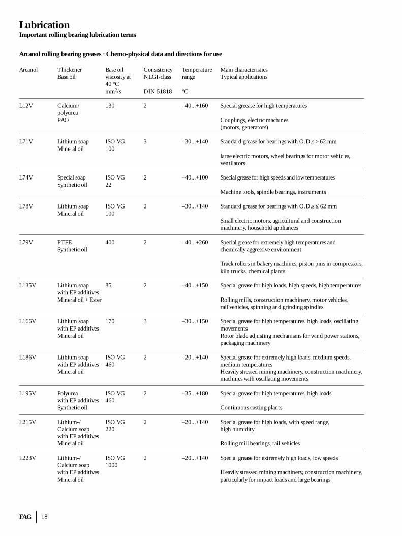
Arcanol rolling bearing greases · Chemo-physical data and directions for use
Arcanol Thickener Base oil Consistency Temperature Main characteristicsBase oil viscosity at NLGI-class range Typical applications
40 °C mm2/s DIN 51818 °C
L12V Calcium/ 130 2 –40...+160 Special greease for high temperaturespolyureaPAO Couplings, electric machines
(motors, generators)
L71V Lithium soap ISO VG 3 –30...+140 Standard grease for bearings with O.D.s > 62 mmMineral oil 100
large electric motors, wheel bearings for motor vehicles,ventilators
L74V Special soap ISO VG 2 –40...+100 Special grease for high speeds and low temperaturesSynthetic oil 22
Machine tools, spindle bearings, instruments
L78V Lithium soap ISO VG 2 –30...+140 Standard grease for bearings with O.D.s ≤ 62 mmMineral oil 100
Small electric motors, agricultural and construction machinery, household appliances
L79V PTFE 400 2 –40...+260 Special grease for extremely high temperatures and Synthetic oil chemically aggressive environment
Track rollers in bakery machines, piston pins in compressors,kiln trucks, chemical plants
L135V Lithium soap 85 2 –40...+150 Special grease for high loads, high speeds, high temperatureswith EP additivesMineral oil + Ester Rolling mills, construction machinery, motor vehicles,
rail vehicles, spinning and grinding spindles
L166V Lithium soap 170 3 –30...+150 Special grease for high temperatures. high loads, oscillatingwith EP additives movementsMineral oil Rotor blade adjusting mechanisms for wind power stations,
packaging machinery
L186V Lithium soap ISO VG 2 –20...+140 Special grease for extremely high loads, medium speeds, with EP additives 460 medium temperaturesMineral oil Heavily stressed mining machinery, construction machinery,
machines with oscillating movements
L195V Polyurea ISO VG 2 –35...+180 Special grease for high temperatures, high loadswith EP additives 460Synthetic oil Continuous casting plants
L215V Lithium-/ ISO VG 2 –20...+140 Special grease for high loads, with speed range, Calcium soap 220 high humiditywith EP additivesMineral oil Rolling mill bearings, rail vehicles
L223V Lithium-/ ISO VG 2 –20...+140 Special grease for extremely high loads, low speedsCalcium soap 1000with EP additives Heavily stressed mining machinery, construction machinery,Mineral oil particularly for impact loads and large bearings
19 FAG
LubricationImportant rolling bearing lubrication terms
Grease life
The grease life F10 is the period from start-up of a bearing until its failure due to lubrication breakdown. The grease lifedepends on the– amount of grease,– grease type (thickener, base oil, additives),– bearing type and size,– type and amount of loading,– speed index,– bearing temperature.
Lithium soap base greases
have definite performance merits in terms of water resistanceand width of temperature range. Frequently, they incorporateoxidation inhibitors, corrosion inhibitors and EP additives.Due to their favourable properties, lithium soap base greasesare widely used as rolling bearing greases. Standard lithiumsoap base greases can be used at temperatures ranging from–35 °C to +130 °C.
Lubricating conditions
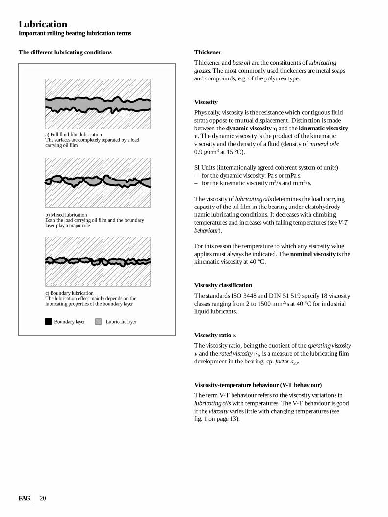
The following lubricating conditions exist in a rolling bearing(see illustration on page 20):
– Full fluid film lubrication: The surfaces of the componentsin relative motion are separated by a lubricant film. Forcontinuous operation this type of lubrication, which is alsoreferred to as fluid lubrication, should always be aimed at.
– Mixed lubrication: Where the lubricant film gets too thin,local metal-to-metal contact occurs, resulting in mixed fric-tion.
– Boundary lubrication: If the lubricant contains suitable additives, reactions between the additives and the metalsurfaces are triggered at the high pressures and tempera-tures in the contact areas. The resulting reaction productshave a lubricating effect and form a thin boundary layer.
Lubricating greases
Greases are consistent mixtures of thickeners and base oils. The following grease types are distinguished:– Metal soap base greases consisting of metal soaps as
thickeners and lubricating oils,– Non-soap greases comprising inorganic gelling agents or
organic thickeners and lubricating oils,– Synthetic greases consisting of organic or inorganic
thickeners and synthetic oils.
Lubricating oils
Rolling bearings can be lubricated either with mineral oils orsynthetic oils. Today, mineral oils are most frequently used.
Lubrication interval
The lubrication interval corresponds to the minimum greaselife F10 of standard greases in accordance with DIN 51 825,see lubrication interval curve in the FAG publication No. WL 81 115. This value is assumed if the grease life F10 of thegrease used is not known.Influences which reduce the lubrication interval are taken intoaccount by reduction factors.
Mineral oils
Crude oils and/or their liquid derivates. Mineral oils used tolubricate rolling bearings must at least meet the requirementsdefined in DIN 51501.Cp. also Synthetic lubricants.
Operating viscosity �
Kinematic viscosity of an oil at operating temperature. Cp. alsoViscosity ratio � and Attainable life.
Rated viscosity �1
The rated viscosity is the kinematic viscosity attributed to a defined lubrication condition. Cp. also Viscosity ratio � and Attainable life.
Relubrication interval
Period after which lubricant is replenished. The relubricationinterval should be shorter than the lubricant renewal interval.
Speed index n · dm
Product from the operating speed n [min–1] and the meanbearing diameter dm [mm] dm = (D + d)/2D = bearing outside diameter [mm], d = bearing bore [mm]The speed index is predominantly used when selecting suit-able lubrication modes and lubricants.
Synthetic lubricants/synthetic oils
Lubricating oils produced by chemical synthesis; their prop-erties can be adapted to meet special requirements: very lowsetting point, good V-T behaviour, small evaporation losses,long life, high oxidation stability.
FAG 20
LubricationImportant rolling bearing lubrication terms
The different lubricating conditions Thickener
Thickener and base oil are the constituents of lubricatinggreases. The most commonly used thickeners are metal soapsand compounds, e.g. of the polyurea type.
Viscosity
Physically, viscosity is the resistance which contiguous fluidstrata oppose to mutual displacement. Distinction is madebetween the dynamic viscosity � and the kinematic viscosity�. The dynamic viscosity is the product of the kinematic viscosity and the density of a fluid (density of mineral oils:0.9 g/cm3 at 15 °C).
SI Units (internationally agreed coherent system of units)– for the dynamic viscosity: Pa s or mPa s.– for the kinematic viscosity m2/s and mm2/s.
The viscosity of lubricating oils determines the load carryingcapacity of the oil film in the bearing under elastohydrody-namic lubricating conditions. It decreases with climbingtemperatures and increases with falling temperatures (see V-Tbehaviour).
For this reason the temperature to which any viscosity valueapplies must always be indicated. The nominal viscosity is thekinematic viscosity at 40 °C.
Viscosity classification
The standards ISO 3448 and DIN 51 519 specify 18 viscosityclasses ranging from 2 to 1500 mm2/s at 40 °C for industrialliquid lubricants.
Viscosity ratio �
The viscosity ratio, being the quotient of the operating viscosity� and the rated viscosity �1, is a measure of the lubricating filmdevelopment in the bearing, cp. factor a23.
Viscosity-temperature behaviour (V-T behaviour)
The term V-T behaviour refers to the viscosity variations in lubricating oils with temperatures. The V-T behaviour is goodif the viscosity varies little with changing temperatures (see fig. 1 on page 13).
a) Full fluid film lubricationThe surfaces are completely separated by a loadcarrying oil film
b) Mixed lubricationBoth the load carrying oil film and the boundarylayer play a major role
c) Boundary lubricationThe lubrication effect mainly depends on thelubricating properties of the boundary layer
Boundary layer Lubricant layer
21 FAG
Seals
SealsThe seal should, on the one hand, prevent the lubricating grease or oil from escaping from the bearing and, on the otherhand, prevent contaminants from entering the bearing. Theeffectiveness of a seal has a considerable influence on the service life of a bearing arrangement.
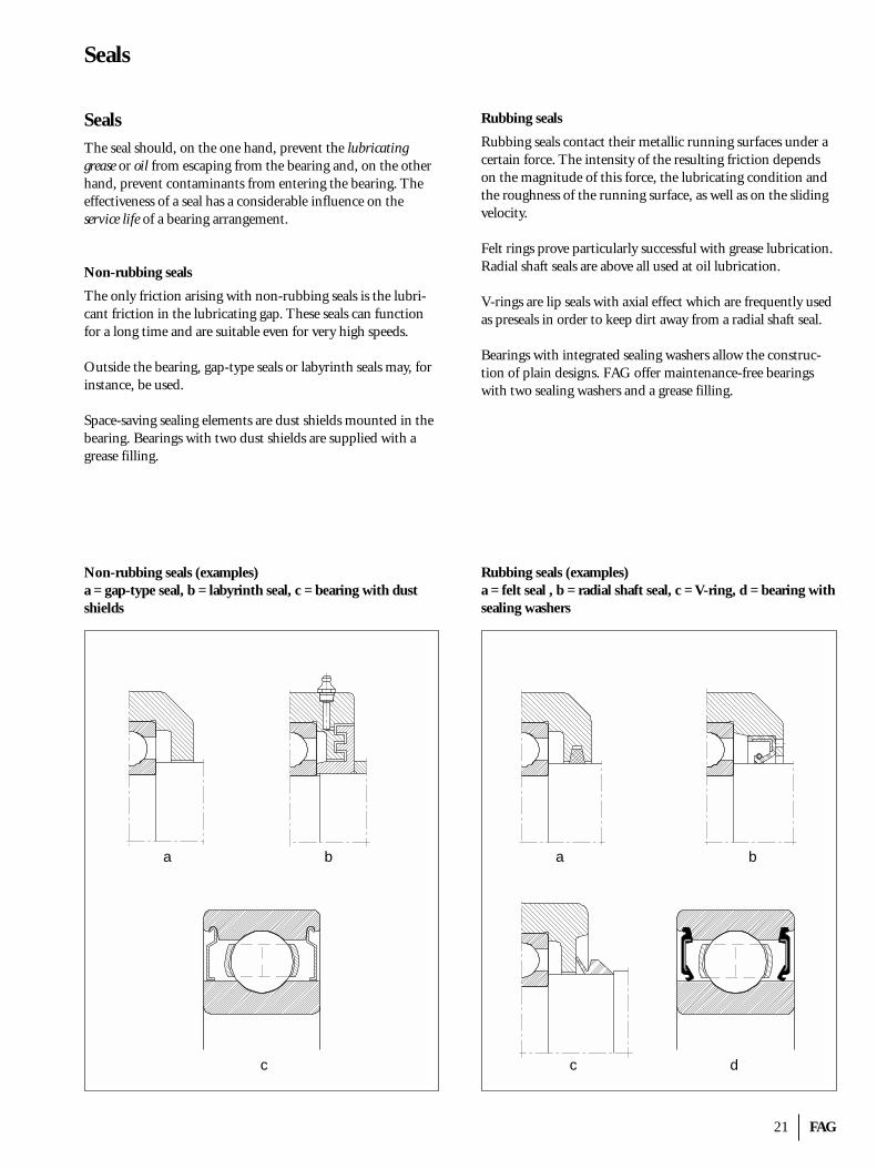
Non-rubbing seals
The only friction arising with non-rubbing seals is the lubri-cant friction in the lubricating gap. These seals can functionfor a long time and are suitable even for very high speeds.
Outside the bearing, gap-type seals or labyrinth seals may, forinstance, be used.
Space-saving sealing elements are dust shields mounted in thebearing. Bearings with two dust shields are supplied with agrease filling.
Non-rubbing seals (examples)a = gap-type seal, b = labyrinth seal, c = bearing with dustshields
Rubbing seals
Rubbing seals contact their metallic running surfaces under acertain force. The intensity of the resulting friction dependson the magnitude of this force, the lubricating condition andthe roughness of the running surface, as well as on the slidingvelocity.
Felt rings prove particularly successful with grease lubrication.Radial shaft seals are above all used at oil lubrication.
V-rings are lip seals with axial effect which are frequently usedas preseals in order to keep dirt away from a radial shaft seal.
Bearings with integrated sealing washers allow the construc-tion of plain designs. FAG offer maintenance-free bearingswith two sealing washers and a grease filling.
Rubbing seals (examples)a = felt seal , b = radial shaft seal, c = V-ring, d = bearing withsealing washers
a b
c
a b
c d
FAG 22
Speed suitability
Speed suitabilityGenerally, the maximum attainable speed of rolling bearings isdictated by the permissible operating temperatures. This lim-iting criterion takes into account the (thermal) reference speed.
The limiting speed may be higher or lower than the referencespeed. It is indicated in the FAG catalogues also for bearingsfor which – according to DIN 732 – no reference speed is defined. The limiting speed may only be exceeded on consulta-tion with FAG.
In the catalogue WL 41 520 EA "FAG Rolling Bearings" a reference is made to a method based on DIN 732, Part 2, fordetermining the thermally permissible operating speed on thebasis of the reference speed for cases where the operating condi-tions (load, oil viscosity or permissible temperature) deviatefrom the reference conditions.
Limiting speed
Decisive criteria for the limiting speed are e.g. the strength limit of the bearing parts or the permissible sliding velocity ofrubbing seals. Limiting speeds which are higher than the reference speeds can be reached, for example, with
– specially designed lubrication– bearing clearance adapted to the operating conditions– accurate machining of the bearing seats– special regard to heat dissipation
Reference speed
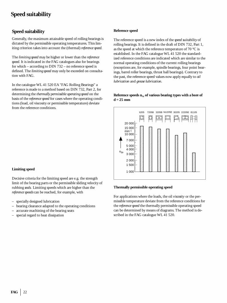
The reference speed is a new index of the speed suitability ofrolling bearings. It is defined in the draft of DIN 732, Part 1,as the speed at which the reference temperature of 70 °C isestablished. In the FAG catalogue WL 41 520 the standard-ized reference conditions are indicated which are similar to thenormal operating conditions of the current rolling bearings(exceptions are, for example, spindle bearings, four point bear-ings, barrel roller bearings, thrust ball bearings). Contrary tothe past, the reference speed values now apply equally to oil lubrication and grease lubrication.
Reference speeds n�r of various bearing types with a bore of d = 25 mm
Thermally permissible operating speed
For applications where the loads, the oil viscosity or the per-missible temperature deviate from the reference conditions forthe reference speed the thermally permissible operating speedcan be determined by means of diagrams. The method is de-scribed in the FAG catalogue WL 41 520.
1 000
1 500
2 000
3 000
4 0005 000
7 000
10 000
15 000
20 000
min-1
nΘr
6205 7205B NU205E3205B 30205 22205E 81105
23 FAG
High temperature suitability
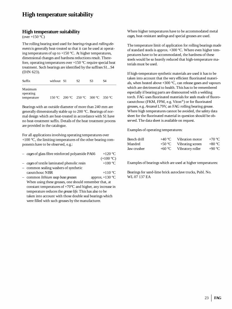
High temperature suitability(over +150 °C)
The rolling bearing steel used for bearing rings and rolling ele-ments is generally heat-treated so that it can be used at operat-ing temperatures of up to +150 °C. At higher temperatures,dimensional changes and hardness reductions result. There-fore, operating temperatures over +150 °C require special heattreatment. Such bearings are identified by the suffixes S1...S4(DIN 623).
Suffix without S1 S2 S3 S4
Maximumoperatingtemperature 150 °C 200 °C 250 °C 300 °C 350 °C
Bearings with an outside diameter of more than 240 mm aregenerally dimensionally stable up to 200 °C. Bearings of nor-mal design which are heat-treated in accordance with S1 haveno heat-treatment suffix. Details of the heat treatment processare provided in the catalogue.
For all applications involving operating temperatures over+100 °C, the limiting temperatures of the other bearing com-ponents have to be observed, e.g.:
– cages of glass fibre reinforced polyamide PA66 +120 °C(+100 °C)
– cages of textile laminated phenolic resin +100 °C– common sealing washers of synthetic
caoutchouc NBR +110 °C– common lithium soap base greases approx. +130 °C
When using these greases, one should remember that, atconstant temperatures of +70°C and higher, any increase intemperature reduces the grease life. This has also to be taken into account with those double seal bearings whichwere filled with such greases by the manufacturer.
Where higher temperatures have to be accommodated metalcages, heat-resistant sealings and special greases are used.
The temperature limit of application for rolling bearings madeof standard steels is approx. +300 °C. Where even higher tem-peratures have to be accommodated, the hardness of thesesteels would be so heavily reduced that high-temperature ma-terials must be used.
If high-temperature synthetic materials are used it has to be taken into account that the very efficient fluorinated materi-als, when heated above +300 °C, can release gases and vapourswhich are detrimental to health. This has to be rememberedespecially if bearing parts are dismounted with a weldingtorch. FAG uses fluorinated materials for seals made of fluoro-caoutchouc (FKM, FPM, e.g. Viton®) or for fluorinated greases, e.g. Arcanol L79V, an FAG rolling bearing grease.Where high temperatures cannot be avoided, the safety datasheet for the fluorinated material in question should be ob-served. The data sheet is available on request.
Examples of operating temperatures:
Bench drill +40 °C Vibration motor +70 °CMandrel +50 °C Vibrating screen +80 °CJaw crusher +60 °C Vibratory roller +90 °C
Examples of bearings which are used at higher temperatures:
Bearings for sand-lime brick autoclave trucks, Publ. No. WL 07 137 EA
FAG 24
Bearing clearance
Bearing clearanceThe bearing clearance is the distance by which one bearingring can be freely displaced in relation to the other one. Withaxial clearance the bearing is displaced along its axis, with radial clearance vertically to the bearing axis.
Gr radial bearing clearanceGa axial bearing clearance
Depending on the bearing type, either the radial or the axialbearing clearance is decisive. It is standardized in DIN 620 formost bearing types and sizes and classified in bearing clearancegroups designated C1...C4.
Clearance group Bearing clearanceSuffix
C1 smaller than C2C2 smaller than normal– normalC3 larger than normalC4 larger than C3
The suffix identifying the clearance group is added to thebearing code; no suffix is used for the clearance group "normal" (CN).
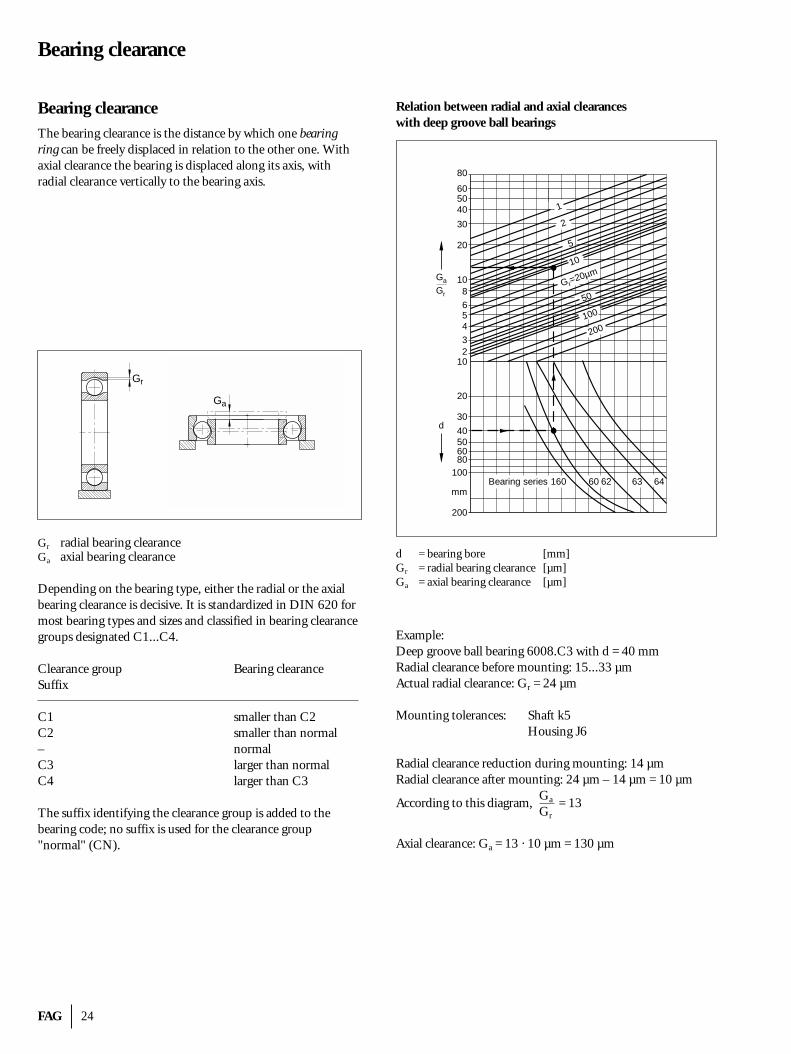
Relation between radial and axial clearances with deep groove ball bearings
d = bearing bore [mm]Gr = radial bearing clearance [µm]Ga = axial bearing clearance [µm]
Example:Deep groove ball bearing 6008.C3 with d = 40 mmRadial clearance before mounting: 15...33 µmActual radial clearance: Gr = 24 µm
Mounting tolerances: Shaft k5Housing J6
Radial clearance reduction during mounting: 14 µmRadial clearance after mounting: 24 µm – 14 µm = 10 µm
According to this diagram,Ga = 13Gr
Axial clearance: Ga = 13 · 10 µm = 130 µm
Gr
1
2
5
10
Gr=20µm
50
100
200
160 60 62 63 64
80
605040
30
20
108
654
32
10
20
30
40506080
100
200
mmBearing series
d
Gr
Ga
Ga
25 FAG
Bearing clearance
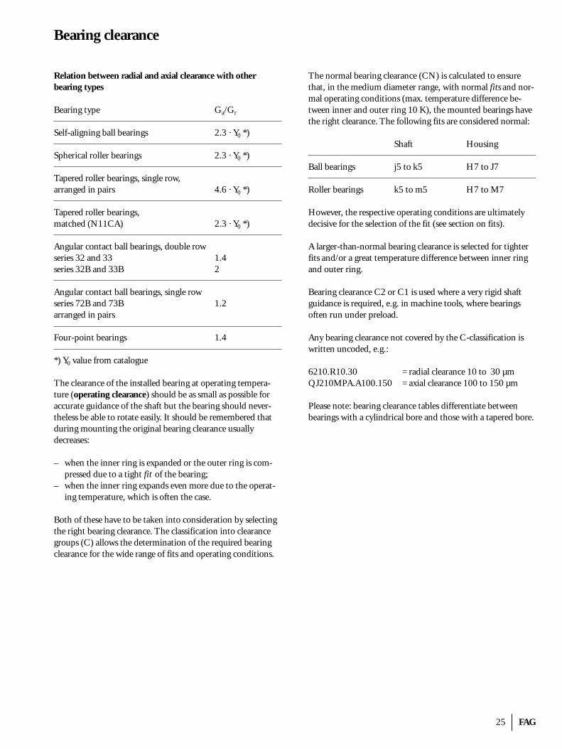
Relation between radial and axial clearance with other bearing types
Bearing type Ga/Gr
Self-aligning ball bearings 2.3 · Y0 *)
Spherical roller bearings 2.3 · Y0 *)
Tapered roller bearings, single row,arranged in pairs 4.6 · Y0 *)
Tapered roller bearings, matched (N11CA) 2.3 · Y0 *)
Angular contact ball bearings, double rowseries 32 and 33 1.4series 32B and 33B 2
Angular contact ball bearings, single rowseries 72B and 73B 1.2arranged in pairs
Four-point bearings 1.4
*) Y0 value from catalogue
The clearance of the installed bearing at operating tempera-ture (operating clearance) should be as small as possible foraccurate guidance of the shaft but the bearing should never-theless be able to rotate easily. It should be remembered thatduring mounting the original bearing clearance usuallydecreases:
– when the inner ring is expanded or the outer ring is com-pressed due to a tight fit of the bearing;
– when the inner ring expands even more due to the operat-ing temperature, which is often the case.
Both of these have to be taken into consideration by selectingthe right bearing clearance. The classification into clearancegroups (C) allows the determination of the required bearingclearance for the wide range of fits and operating conditions.
The normal bearing clearance (CN) is calculated to ensurethat, in the medium diameter range, with normal fits and nor-mal operating conditions (max. temperature difference be-tween inner and outer ring 10 K), the mounted bearings havethe right clearance. The following fits are considered normal:
Shaft Housing
Ball bearings j5 to k5 H7 to J7
Roller bearings k5 to m5 H7 to M7
However, the respective operating conditions are ultimatelydecisive for the selection of the fit (see section on fits).
A larger-than-normal bearing clearance is selected for tighterfits and/or a great temperature difference between inner ringand outer ring.
Bearing clearance C2 or C1 is used where a very rigid shaftguidance is required, e.g. in machine tools, where bearings often run under preload.
Any bearing clearance not covered by the C-classification iswritten uncoded, e.g.:
6210.R10.30 = radial clearance 10 to 30 µmQJ210MPA.A100.150 = axial clearance 100 to 150 µm
Please note: bearing clearance tables differentiate betweenbearings with a cylindrical bore and those with a tapered bore.
FAG 26
Tolerances
TolerancesThe tolerances of rolling bearings are standardized accordingto DIN 620 Part 2 (radial bearings) and DIN 620 Part 3(thrust bearings). The tolerances are laid down for the dimen-sional and running accuracy of the bearings or bearing rings.
Beginning with PN (normal tolerance), there are toleranceclasses P6, P6X, P5, P4 and P2 for precision bearings, theprecision of which is the greater the lower the number. In addition, there are the (non-standardized) FAG tolerance classes SP (Super Precision) and UP (Ultra Precision) fordouble-row cylindrical roller bearings and P4S for spindlebearings. These bearings are mainly used in machine tools.
The suffix for the tolerance class is always added to the bearingcode, with the exception of PN for the normal clearance,which is omitted.
Please remember that bearings in inch dimensions have differ-ent tolerance systems (ABMA tolerances).
Bore diameter
�dmp = dmp – dMean bore diameter deviation from nominal dimension
�d1mp = d1mp – d1
Deviation of mean large diameter from nominaldimension (tapered bore)
Vdp Bore diameter variation; difference between maximum and minimum bore diameter in a singleradial plane
Vdmp = dmpmax – dmpmin
Mean bore diameter variation; difference betweenmaximum and minimum mean bore diameter
Outside diameter
�Dmp = Dmp – DMean O.D. deviation from nominal dimension
VDp O.D. variation; difference between maximum andminimum O.D. in a single radial plane
VDmp = Dmpmax – Dmpmin
Mean O.D. variation; difference between maxi-mum and minimum mean O.D.
Width and height
�Bs = Bs – B, �Cs = Cs – CDeviation of a single ring width (inner or outerring) from nominal dimension
VBs = Bsmax – Bsmin, VCs = Csmax – Csmin
Variation of inner ring width or outer ring width;difference between maximum and minimum measured ring width
�Ts = Ts – T, �T1s = T1s – T1, �T2s = T2s – T2
Deviation of a single overall tapered roller bearingheight from nominal dimension
*) �Hs = Hs – H, �H1s = H1s – H1, �H2s = H2s – H2, ...Deviation of a single overall thrust bearing heightfrom nominal dimension
Running accuracy
Kia Radial runout of inner ring of assembled bearingKea Radial runout of outer ring of assembled bearingSi Washer raceway to back face thickness variation
(thrust bearing shaft washer)Se Washer raceway to back face thickness variation
(thrust bearing housing washer)
*) In the standard, the overall height of thrust bearings is designated T.
27 FAG
Alignment
AlignmentThe machining of the bearing seats on a shaft or in a housingcan lead to misalignment, particularly when the seats are notmachined in one setting. Misalignment can also be expectedto occur where single housings such as flanged housings orplummer block housings are used. Tilting of bearing rings relative to each other as a result of shaft inflections broughtabout by operating loads has similar effects.
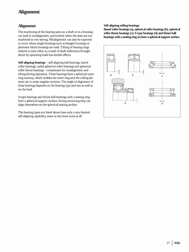
Self-aligning bearings – self-aligning ball bearings, barrel roller bearings, radial spherical roller bearings and sphericalroller thrust bearings – compensate for misalignment and tilting during operation. These bearings have a spherical outerring raceway, which enables the inner ring and the rolling ele-ment set to make angular motions. The angle of alignment ofthese bearings depends on the bearing type and size as well ason the load.
S-type bearings and thrust ball bearings with a seating ringhave a spherical support surface; during mounting they canalign themselves on the spherical mating surface.
The bearing types not listed above have only a very limitedself-aligning capability, some in fact have none at all.
Self-aligning rolling bearings:Barrel roller bearings (a), spherical roller bearings (b), sphericalroller thrust bearings (c); S-type bearings (d) and thrust ballbearings with a seating ring (e) have a spherical support surface.
a b c
ed
FAG 28
Fits
FitsThe fit of a rolling bearing determines how tightly or looselythe bearing sits on the shaft and in the housing.
As a rule, both bearing rings should be tightly fitted for the following reasons:– easiest and safest means of ring retention in circumferential
direction – complete support of the rings over their entire circumfer-
ence; in this way full utilization of the bearing's load carry-ing capacity is possible.
On the other hand, a loose fit is often necessary in practice:– it facilitates mounting of non-separable bearings– it permits displacement of non-separable bearings in longi-
tudinal direction as floating bearings.
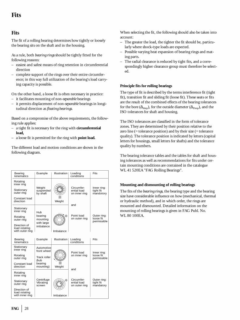
Based on a compromise of the above requirements, the follow-ing rule applies:– a tight fit is necessary for the ring with circumferential
load,– a loose fit is permitted for the ring with point load.
The different load and motion conditions are shown in thefollowing diagram.
When selecting the fit, the following should also be taken intoaccount:– The greater the load, the tighter the fit should be, particu-
larly where shock-type loads are expected.– Possible varying heat expansion of bearing rings and mat-
ing parts.– The radial clearance is reduced by tight fits, and a corre-
spondingly higher clearance group must therefore be select-ed.
Principle fits for rolling bearings
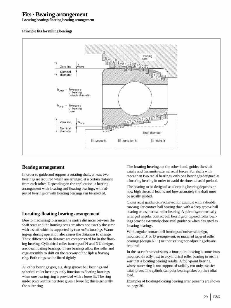
The type of fit is described by the terms interference fit (tightfit), transition fit and sliding fit (loose fit). These seats or fitsare the result of the combined effects of the bearing tolerancesfor the bore (∆dmp), for the outside diameter (∆Dmp), and theISO tolerances for shaft and housing.
The ISO tolerances are classified in the form of tolerance zones. They are determined by their position relative to thezero line (= tolerance position) and by their size (= tolerancequality). The tolerance position is indicated by letters (capitalletters for housings, small letters for shafts) and the tolerancequality by numbers.
The bearing tolerance tables and the tables for shaft and hous-ing tolerances as well as recommendations for fits under cer-tain mounting conditions are contained in the catalogue WL 41 520EA "FAG Rolling Bearings".
Mounting and dismounting of rolling bearings
The fits of the bearing rings, the bearing type and the bearingsize have considerable influence on how (mechanical, thermalor hydraulic method), and in which order, the rings aremounted and dismounted. Detailed information on the mounting of rolling bearings is given in FAG Publ. No. WL 80 100EA.
Bearingkinematics
Example Illustration Loadingconditions
Fits
Weightsuspendedby shaft
Circumfer-ential loadon inner ring
Inner ring:tight fitmandotory
Hubbearingmountingwith largeimbalance
Point loadon outer ring
Outer ring:loose fitpermissible
Rotatinginner ring
Stationaryouter ring
Constant loaddirection Weight
andStationaryinner ring
Rotatingouter ring
Direction ofload rotatingwith outer ring Imbalance
Bearingkinematics
Example Illustration Loadingconditions
Fits
Automotivefront wheel
Track roller(hubbearingmounting)
Point loadon inner ring
Inner ring:loose fitpermissible
CentrifugeVibratingscreen
Circumfer-ential loadon outer ring
Outer ring:tight fitmandatory
Stationaryinner ring
Rotatingouter ring
Constant loaddirection Weight
andRotatinginner ring
Stationaryouter ring
Direction ofload rotatingwith inner ring Imbalance
29 FAG
Fits · Bearing arrangementLocating bearing/floating bearing arrangement
Bearing arrangementIn order to guide and support a rotating shaft, at least twobearings are required which are arranged at a certain distancefrom each other. Depending on the application, a bearing arrangement with locating and floating bearings, with ad-justed bearings or with floating bearings can be selected.
Locating-floating bearing arrangementDue to machining tolerances the centre distances between theshaft seats and the housing seats are often not exactly the samewith a shaft which is supported by two radial bearings. Warm-ing-up during operation also causes the distances to change.These differences in distance are compensated for in the float-ing bearing. Cylindrical roller bearings of N and NU designsare ideal floating bearings. These bearings allow the roller andcage assembly to shift on the raceway of the lipless bearingring. Both rings can be fitted tightly.
All other bearing types, e.g. deep groove ball bearings andspherical roller bearings, only function as floating bearingswhen one bearing ring is provided with a loose fit. The ringunder point load is therefore given a loose fit; this is generallythe outer ring.
The locating bearing, on the other hand, guides the shaft axially and transmits external axial forces. For shafts withmore than two radial bearings, only one bearing is designed asa locating bearing in order to avoid detrimental axial preload.
The bearing to be designed as a locating bearing depends onhow high the axial load is and how accurately the shaft mustbe axially guided.
Closer axial guidance is achieved for example with a doublerow angular contact ball bearing than with a deep groove ballbearing or a spherical roller bearing. A pair of symmetricallyarranged angular contact ball bearings or tapered roller bear-ings provide extremely close axial guidance when designed aslocating bearings.
With angular contact ball bearings of universal design,mounted in X or O arrangement, or matched tapered rollerbearings (design N11) neither setting nor adjusting jobs arerequired.
In the case of transmissions, a four-point bearing is sometimesmounted directly next to a cylindrical roller bearing in such away that a locating bearing results. A four-point bearing whose outer ring is not supported radially can only transferaxial forces. The cylindrical roller bearing takes on the radialload.
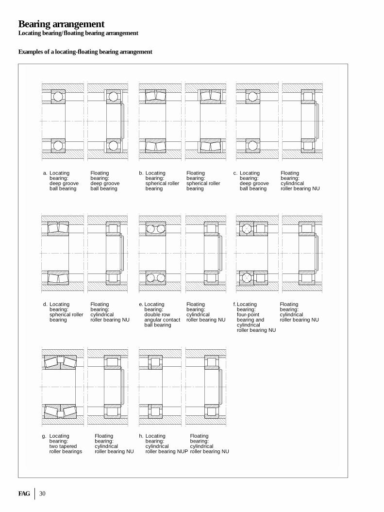
Examples of locating-floating bearing arrangements are shownon page 30.
Principle fits for rolling bearings
∆Dmp
∆Dmp
∆dmp
∆dmp
=
=
+
-
S6R6P6
P7N
6N
7M6
M7
K5
K6K7
JS4
JS5
JS6
JS7
J6J7H5H6H
7
G6 H
8
G7F6F7
E8
s7s6r7
r6p7
p6
p5
n6n5n4m6
m5
k6k5k4js5
js4
js3
j6j5h3h4h5h6h7g6f6
+
- Shaft diameter
Housingbore
Loose fit Transition fit Tight fit
Toleranceof bearingoutside diameter
Toleranceof bearingbore
Zero line
Nominaldiameter
Zero line
Nominaldiameter
FAG 30
Bearing arrangementLocating bearing/floating bearing arrangement
Locatingbearing:deep grooveball bearing
a. Floatingbearing:deep grooveball bearing
Locatingbearing:spherical rollerbearing
b. Floatingbearing:spherical rollerbearing
Locatingbearing:deep grooveball bearing
c. Floatingbearing:cylindricalroller bearing NU
Locatingbearing:spherical rollerbearing
d. Floatingbearing:cylindricalroller bearing NU
Locatingbearing:double rowangular contactball bearing
e. Floatingbearing:cylindricalroller bearing NU
Locatingbearing:four-pointbearing andcylindricalroller bearing NU
f.
Locatingbearing:two taperedroller bearings
g. Floatingbearing:cylindricalroller bearing NU
Locatingbearing:cylindricalroller bearing NUP
h. Floatingbearing:cylindricalroller bearing NU
Floatingbearing:cylindricalroller bearing NU
Examples of a locating-floating bearing arrangement
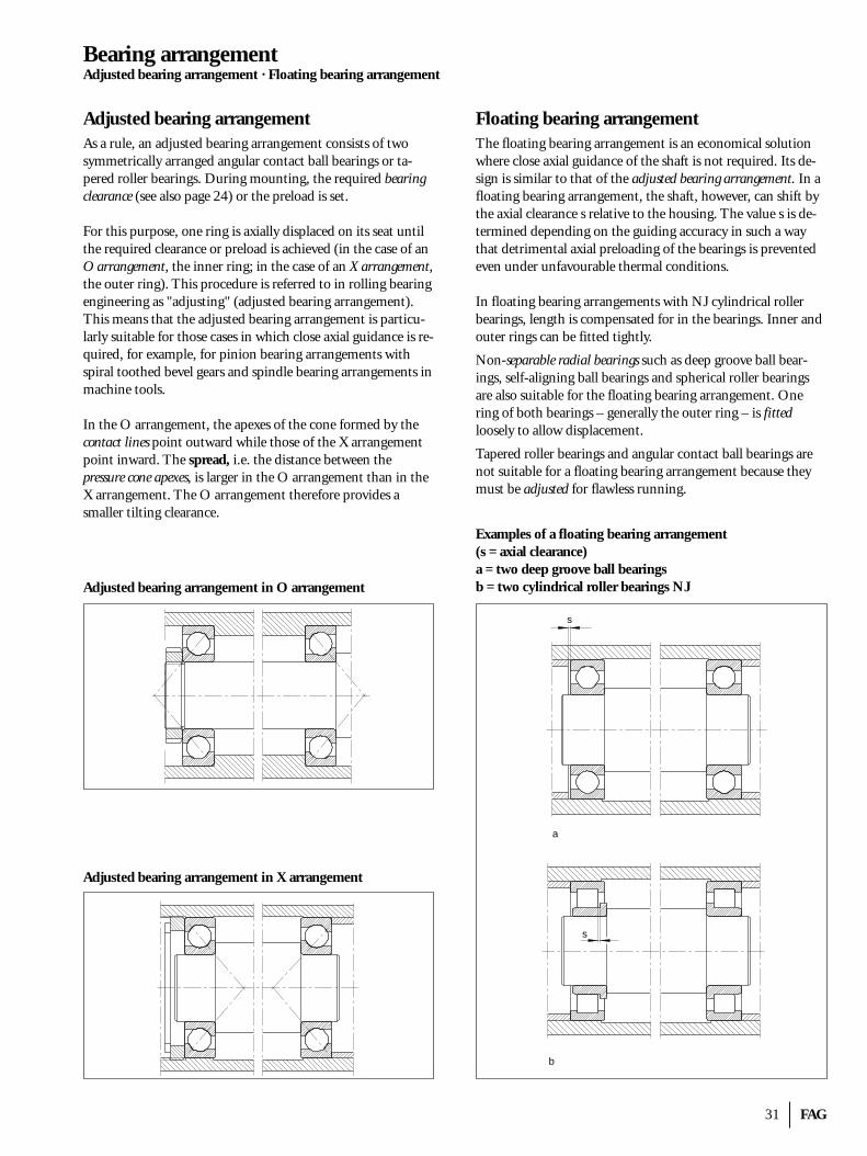
31 FAG
Bearing arrangementAdjusted bearing arrangement · Floating bearing arrangement
Adjusted bearing arrangementAs a rule, an adjusted bearing arrangement consists of twosymmetrically arranged angular contact ball bearings or ta-pered roller bearings. During mounting, the required bearingclearance (see also page 24) or the preload is set.
For this purpose, one ring is axially displaced on its seat untilthe required clearance or preload is achieved (in the case of anO arrangement, the inner ring; in the case of an X arrangement,the outer ring). This procedure is referred to in rolling bearingengineering as "adjusting" (adjusted bearing arrangement).This means that the adjusted bearing arrangement is particu-larly suitable for those cases in which close axial guidance is re-quired, for example, for pinion bearing arrangements with spiral toothed bevel gears and spindle bearing arrangements inmachine tools.
In the O arrangement, the apexes of the cone formed by thecontact lines point outward while those of the X arrangementpoint inward. The spread, i.e. the distance between the pressure cone apexes, is larger in the O arrangement than in theX arrangement. The O arrangement therefore provides a smaller tilting clearance.
Adjusted bearing arrangement in O arrangement
Adjusted bearing arrangement in X arrangement
Floating bearing arrangementThe floating bearing arrangement is an economical solutionwhere close axial guidance of the shaft is not required. Its de-sign is similar to that of the adjusted bearing arrangement. In afloating bearing arrangement, the shaft, however, can shift bythe axial clearance s relative to the housing. The value s is de-termined depending on the guiding accuracy in such a waythat detrimental axial preloading of the bearings is preventedeven under unfavourable thermal conditions.
In floating bearing arrangements with NJ cylindrical rollerbearings, length is compensated for in the bearings. Inner andouter rings can be fitted tightly.
Non-separable radial bearings such as deep groove ball bear-ings, self-aligning ball bearings and spherical roller bearingsare also suitable for the floating bearing arrangement. Onering of both bearings – generally the outer ring – is fittedloosely to allow displacement.
Tapered roller bearings and angular contact ball bearings arenot suitable for a floating bearing arrangement because theymust be adjusted for flawless running.
Examples of a floating bearing arrangement(s = axial clearance)a = two deep groove ball bearingsb = two cylindrical roller bearings NJ
b
a
s
s
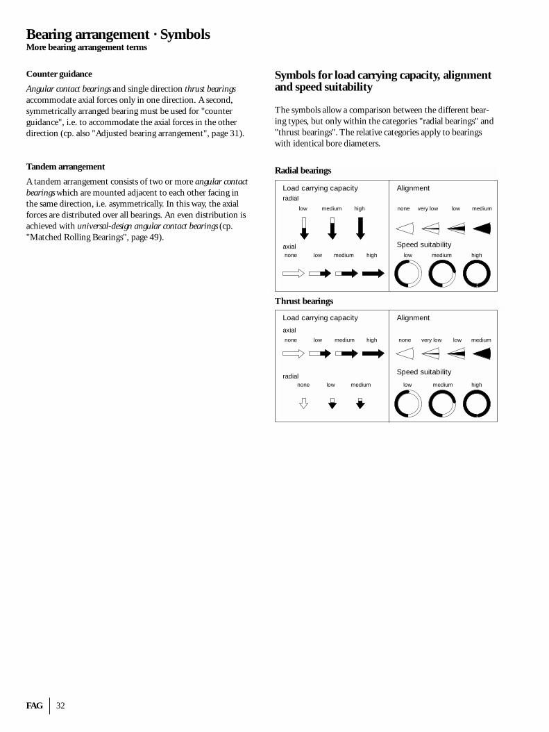
FAG 32
Bearing arrangement · SymbolsMore bearing arrangement terms
Counter guidance
Angular contact bearings and single direction thrust bearingsaccommodate axial forces only in one direction. A second,symmetrically arranged bearing must be used for "counterguidance", i.e. to accommodate the axial forces in the otherdirection (cp. also "Adjusted bearing arrangement", page 31).
Tandem arrangement
A tandem arrangement consists of two or more angular contactbearings which are mounted adjacent to each other facing inthe same direction, i.e. asymmetrically. In this way, the axialforces are distributed over all bearings. An even distribution isachieved with universal-design angular contact bearings (cp."Matched Rolling Bearings", page 49).
Symbols for load carrying capacity, alignmentand speed suitability
The symbols allow a comparison between the different bear-ing types, but only within the categories "radial bearings" and"thrust bearings". The relative categories apply to bearingswith identical bore diameters.
Load carrying capacity
low medium high
low medium highnone
axial
Alignment
none very low low medium
Load carrying capacity
low mediumnone
radial
Alignment
Speed suitability
none very low low medium
low medium high
radial
axial
Axiallager
low medium highnone
Speed suitabilitylow medium high
Radial bearings
Thrust bearings
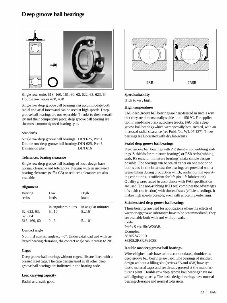
33 FAG
Deep groove ball bearings
Single row: series 618, 160, 161, 60, 62, 622, 63, 623, 64Double row: series 42B, 43B
Single row deep groove ball bearings can accommodate bothradial and axial forces and can be used at high speeds. Deepgroove ball bearings are not separable. Thanks to their versatil-ity and their competitive price, deep groove ball bearing arethe most commonly used bearing type.
Standards
Single row deep groove ball bearings DIN 625, Part 1Double row deep groove ball bearings DIN 625, Part 3Dimension plan DIN 616
Tolerances, bearing clearance
Single row deep groove ball bearings of basic design have normal clearance and tolerances. Designs with an increasedbearing clearance (suffix C3) or reduced tolerances are alsoavailable.
Alignment
Bearing Low Highseries loads loads
in angular minutes in angular minutes62, 622, 63, 5...10' 8...16'623, 64618, 160, 60 2...6' 5...10'
Contact angle
Nominal contact angle �0 = 0°. Under axial load and with en-larged bearing clearance, the contact angle can increase to 20°.
Cages
Deep groove ball bearings without cage suffix are fitted with apressed steel cage. The cage designs used in all other deepgroove ball bearings are indicated in the bearing code.
Load carrying capacity
Radial and axial: good.
Speed suitability
High to very high.
High temperatures
FAG deep groove ball bearings are heat-treated in such a waythat they are dimensionally stable up to 150 °C. For applica-tion in sand-lime brick autoclave trucks, FAG offers deepgroove ball bearings which were specially heat-treated, with anincreased radial clearance (see Publ. No. WL 07 137). Thesebearings are lubricated with dry lubricants.
Sealed deep groove ball bearings
Deep groove ball bearings with ZR shields (non-rubbing seal-ings, Z shields for miniature bearings) or RSR seals (rubbingseals, RS seals for miniature bearings) make simple designspossible. The bearings can be sealed either on one side or onboth sides. In the latter case the bearings are provided with agrease filling during production which, under normal operat-ing conditions, is sufficient for life (for-life lubrication). Quality greases tested in accordance with FAG specificationare used. The non-rubbing RSD seal combines the advantagesof shields (no friction) with those of seals (efficient sealing). Itmakes high speeds possible, even with a rotating outer ring.
Stainless steel deep groove ball bearings
These bearings are used for applications where the effects ofwater or aggressive substances have to be accommodated; theyare available both with and without seals.Code:Prefix S + suffix W203B.Examples:S6205.W203BS6205.2RSR.W203B.
Double row deep groove ball bearings
Where higher loads have to be accommodated, double rowdeep groove ball bearings are used. The bearings of standarddesign without a filling slot (series 42B and 43B) have syn-thetic material cages and are already greased at the manufac-turer's plant. Double row deep groove ball bearings have noself-aligning capacity. The basic-design bearings have normalbearing clearance and normal tolerances.
.2ZR .2RSR
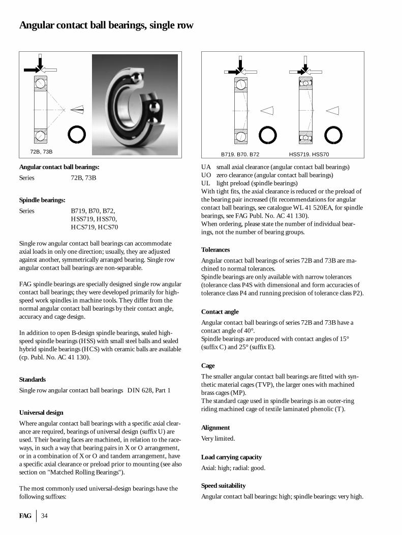
FAG 34
Angular contact ball bearings, single row
Angular contact ball bearings:
Series 72B, 73B
Spindle bearings:
Series B719, B70, B72,HSS719, HSS70, HCS719, HCS70
Single row angular contact ball bearings can accommodateaxial loads in only one direction; usually, they are adjustedagainst another, symmetrically arranged bearing. Single rowangular contact ball bearings are non-separable.
FAG spindle bearings are specially designed single row angularcontact ball bearings; they were developed primarily for high-speed work spindles in machine tools. They differ from thenormal angular contact ball bearings by their contact angle,accuracy and cage design.
In addition to open B-design spindle bearings, sealed high-speed spindle bearings (HSS) with small steel balls and sealedhybrid spindle bearings (HCS) with ceramic balls are available(cp. Publ. No. AC 41 130).
Standards
Single row angular contact ball bearings DIN 628, Part 1
Universal design
Where angular contact ball bearings with a specific axial clear-ance are required, bearings of universal design (suffix U) areused. Their bearing faces are machined, in relation to the race-ways, in such a way that bearing pairs in X or O arrangement,or in a combination of X or O and tandem arrangement, havea specific axial clearance or preload prior to mounting (see alsosection on "Matched Rolling Bearings").
The most commonly used universal-design bearings have thefollowing suffixes:
UA small axial clearance (angular contact ball bearings)UO zero clearance (angular contact ball bearings)UL light preload (spindle bearings)With tight fits, the axial clearance is reduced or the preload ofthe bearing pair increased (fit recommendations for angularcontact ball bearings, see catalogue WL 41 520EA, for spindlebearings, see FAG Publ. No. AC 41 130).When ordering, please state the number of individual bear-ings, not the number of bearing groups.
Tolerances
Angular contact ball bearings of series 72B and 73B are ma-chined to normal tolerances.Spindle bearings are only available with narrow tolerances (tolerance class P4S with dimensional and form accuracies oftolerance class P4 and running precision of tolerance class P2).
Contact angle
Angular contact ball bearings of series 72B and 73B have acontact angle of 40°.Spindle bearings are produced with contact angles of 15°(suffix C) and 25° (suffix E).
Cage
The smaller angular contact ball bearings are fitted with syn-thetic material cages (TVP), the larger ones with machinedbrass cages (MP).The standard cage used in spindle bearings is an outer-ringriding machined cage of textile laminated phenolic (T).
Alignment
Very limited.
Load carrying capacity
Axial: high; radial: good.
Speed suitability
Angular contact ball bearings: high; spindle bearings: very high.
72B, 73B B719, B70, B72 HSS719, HSS70
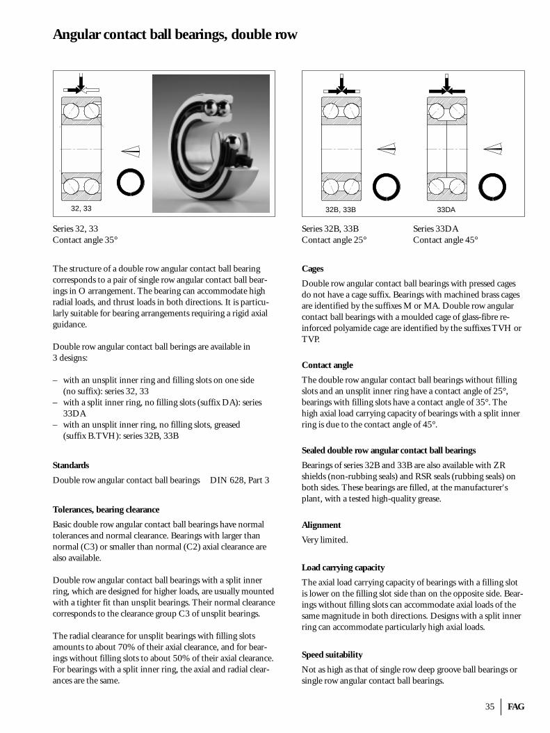
35 FAG
Angular contact ball bearings, double row
Series 32, 33Contact angle 35°
The structure of a double row angular contact ball bearingcorresponds to a pair of single row angular contact ball bear-ings in O arrangement. The bearing can accommodate highradial loads, and thrust loads in both directions. It is particu-larly suitable for bearing arrangements requiring a rigid axialguidance.
Double row angular contact ball berings are available in 3 designs:
– with an unsplit inner ring and filling slots on one side (no suffix): series 32, 33
– with a split inner ring, no filling slots (suffix DA): series33DA
– with an unsplit inner ring, no filling slots, greased (suffix B.TVH): series 32B, 33B
Standards
Double row angular contact ball bearings DIN 628, Part 3
Tolerances, bearing clearance
Basic double row angular contact ball bearings have normaltolerances and normal clearance. Bearings with larger thannormal (C3) or smaller than normal (C2) axial clearance arealso available.
Double row angular contact ball bearings with a split innerring, which are designed for higher loads, are usually mountedwith a tighter fit than unsplit bearings. Their normal clearancecorresponds to the clearance group C3 of unsplit bearings.
The radial clearance for unsplit bearings with filling slots amounts to about 70% of their axial clearance, and for bear-ings without filling slots to about 50% of their axial clearance.For bearings with a split inner ring, the axial and radial clear-ances are the same.
Series 32B, 33B Series 33DAContact angle 25° Contact angle 45°
Cages
Double row angular contact ball bearings with pressed cagesdo not have a cage suffix. Bearings with machined brass cagesare identified by the suffixes M or MA. Double row angularcontact ball bearings with a moulded cage of glass-fibre re-inforced polyamide cage are identified by the suffixes TVH orTVP.
Contact angle
The double row angular contact ball bearings without fillingslots and an unsplit inner ring have a contact angle of 25°,bearings with filling slots have a contact angle of 35°. Thehigh axial load carrying capacity of bearings with a split innerring is due to the contact angle of 45°.
Sealed double row angular contact ball bearings
Bearings of series 32B and 33B are also available with ZRshields (non-rubbing seals) and RSR seals (rubbing seals) onboth sides. These bearings are filled, at the manufacturer'splant, with a tested high-quality grease.
Alignment
Very limited.
Load carrying capacity
The axial load carrying capacity of bearings with a filling slotis lower on the filling slot side than on the opposite side. Bear-ings without filling slots can accommodate axial loads of thesame magnitude in both directions. Designs with a split innerring can accommodate particularly high axial loads.
Speed suitability
Not as high as that of single row deep groove ball bearings orsingle row angular contact ball bearings.
32, 33 32B, 33B 33DA
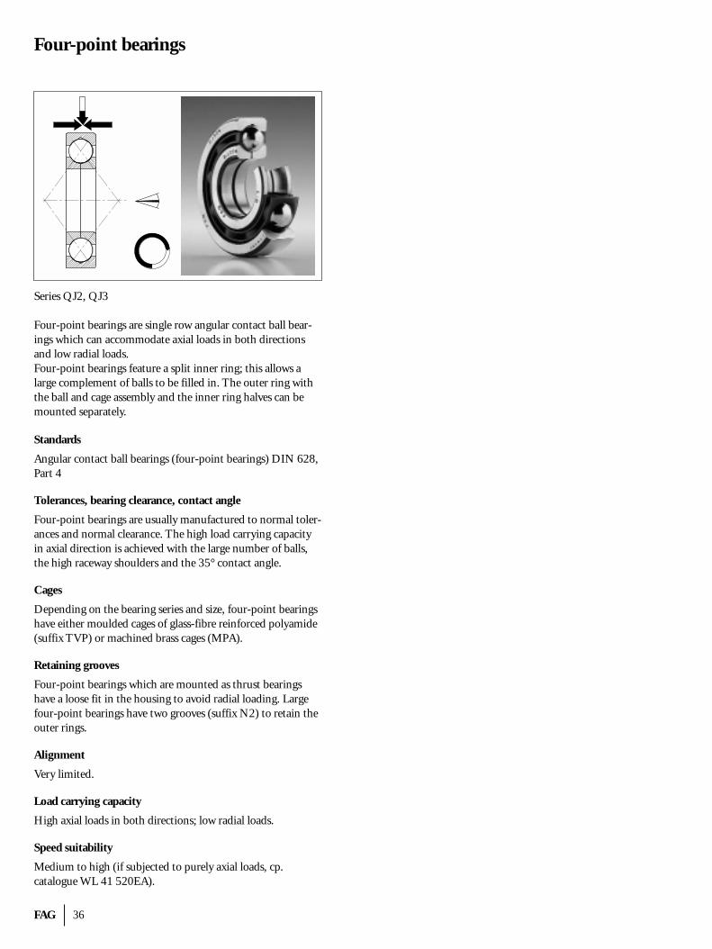
FAG 36
Four-point bearings
Series QJ2, QJ3
Four-point bearings are single row angular contact ball bear-ings which can accommodate axial loads in both directionsand low radial loads.Four-point bearings feature a split inner ring; this allows a large complement of balls to be filled in. The outer ring withthe ball and cage assembly and the inner ring halves can bemounted separately.
Standards
Angular contact ball bearings (four-point bearings) DIN 628,Part 4
Tolerances, bearing clearance, contact angle
Four-point bearings are usually manufactured to normal toler-ances and normal clearance. The high load carrying capacityin axial direction is achieved with the large number of balls,the high raceway shoulders and the 35° contact angle.
Cages
Depending on the bearing series and size, four-point bearingshave either moulded cages of glass-fibre reinforced polyamide(suffix TVP) or machined brass cages (MPA).
Retaining grooves
Four-point bearings which are mounted as thrust bearingshave a loose fit in the housing to avoid radial loading. Largefour-point bearings have two grooves (suffix N2) to retain theouter rings.
Alignment
Very limited.
Load carrying capacity
High axial loads in both directions; low radial loads.
Speed suitability
Medium to high (if subjected to purely axial loads, cp. catalogue WL 41 520EA).
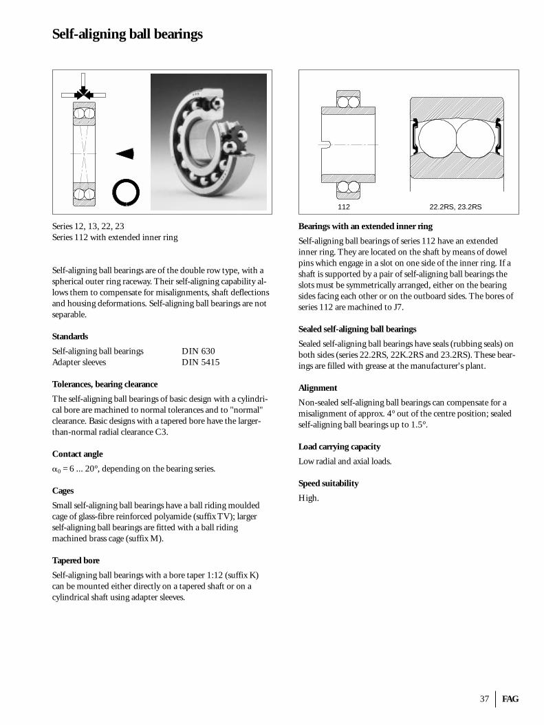
37 FAG
Self-aligning ball bearings
Series 12, 13, 22, 23Series 112 with extended inner ring
Self-aligning ball bearings are of the double row type, with aspherical outer ring raceway. Their self-aligning capability al-lows them to compensate for misalignments, shaft deflectionsand housing deformations. Self-aligning ball bearings are notseparable.
Standards
Self-aligning ball bearings DIN 630Adapter sleeves DIN 5415
Tolerances, bearing clearance
The self-aligning ball bearings of basic design with a cylindri-cal bore are machined to normal tolerances and to "normal"clearance. Basic designs with a tapered bore have the larger-than-normal radial clearance C3.
Contact angle
�0 = 6 ... 20°, depending on the bearing series.
Cages
Small self-aligning ball bearings have a ball riding mouldedcage of glass-fibre reinforced polyamide (suffix TV); largerself-aligning ball bearings are fitted with a ball riding machined brass cage (suffix M).
Tapered bore
Self-aligning ball bearings with a bore taper 1:12 (suffix K)can be mounted either directly on a tapered shaft or on a cylindrical shaft using adapter sleeves.
Bearings with an extended inner ring
Self-aligning ball bearings of series 112 have an extended inner ring. They are located on the shaft by means of dowelpins which engage in a slot on one side of the inner ring. If ashaft is supported by a pair of self-aligning ball bearings theslots must be symmetrically arranged, either on the bearing sides facing each other or on the outboard sides. The bores ofseries 112 are machined to J7.
Sealed self-aligning ball bearings
Sealed self-aligning ball bearings have seals (rubbing seals) onboth sides (series 22.2RS, 22K.2RS and 23.2RS). These bear-ings are filled with grease at the manufacturer's plant.
Alignment
Non-sealed self-aligning ball bearings can compensate for amisalignment of approx. 4° out of the centre position; sealedself-aligning ball bearings up to 1.5°.
Load carrying capacity
Low radial and axial loads.
Speed suitability
High.
112 22.2RS, 23.2RS
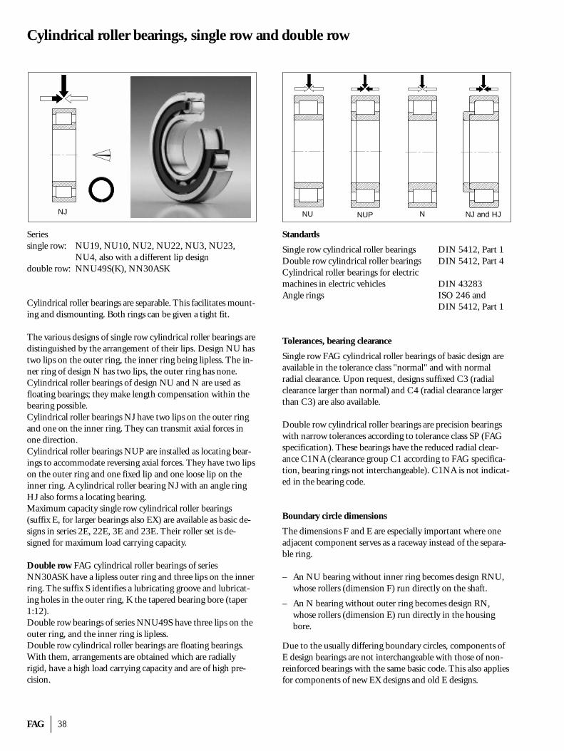
FAG 38
Cylindrical roller bearings, single row and double row
Seriessingle row: NU19, NU10, NU2, NU22, NU3, NU23,
NU4, also with a different lip designdouble row: NNU49S(K), NN30ASK
Cylindrical roller bearings are separable. This facilitates mount-ing and dismounting. Both rings can be given a tight fit.
The various designs of single row cylindrical roller bearings aredistinguished by the arrangement of their lips. Design NU hastwo lips on the outer ring, the inner ring being lipless. The in-ner ring of design N has two lips, the outer ring has none. Cylindrical roller bearings of design NU and N are used asfloating bearings; they make length compensation within thebearing possible.Cylindrical roller bearings NJ have two lips on the outer ringand one on the inner ring. They can transmit axial forces inone direction.Cylindrical roller bearings NUP are installed as locating bear-ings to accommodate reversing axial forces. They have two lipson the outer ring and one fixed lip and one loose lip on the inner ring. A cylindrical roller bearing NJ with an angle ringHJ also forms a locating bearing.Maximum capacity single row cylindrical roller bearings (suffix E, for larger bearings also EX) are available as basic de-signs in series 2E, 22E, 3E and 23E. Their roller set is de-signed for maximum load carrying capacity.
Double row FAG cylindrical roller bearings of seriesNN30ASK have a lipless outer ring and three lips on the innerring. The suffix S identifies a lubricating groove and lubricat-ing holes in the outer ring, K the tapered bearing bore (taper1:12).Double row bearings of series NNU49S have three lips on theouter ring, and the inner ring is lipless.Double row cylindrical roller bearings are floating bearings.With them, arrangements are obtained which are radially rigid, have a high load carrying capacity and are of high pre-cision.
Standards
Single row cylindrical roller bearings DIN 5412, Part 1Double row cylindrical roller bearings DIN 5412, Part 4Cylindrical roller bearings for electric machines in electric vehicles DIN 43283Angle rings ISO 246 and
DIN 5412, Part 1
Tolerances, bearing clearance
Single row FAG cylindrical roller bearings of basic design areavailable in the tolerance class "normal" and with normal radial clearance. Upon request, designs suffixed C3 (radialclearance larger than normal) and C4 (radial clearance largerthan C3) are also available.
Double row cylindrical roller bearings are precision bearingswith narrow tolerances according to tolerance class SP (FAGspecification). These bearings have the reduced radial clear-ance C1NA (clearance group C1 according to FAG specifica-tion, bearing rings not interchangeable). C1NA is not indicat-ed in the bearing code.
Boundary circle dimensions
The dimensions F and E are especially important where oneadjacent component serves as a raceway instead of the separa-ble ring.
– An NU bearing without inner ring becomes design RNU,whose rollers (dimension F) run directly on the shaft.
– An N bearing without outer ring becomes design RN,whose rollers (dimension E) run directly in the housingbore.
Due to the usually differing boundary circles, components ofE design bearings are not interchangeable with those of non-reinforced bearings with the same basic code. This also appliesfor components of new EX designs and old E designs.
NJ NUP N NJ and HJNU
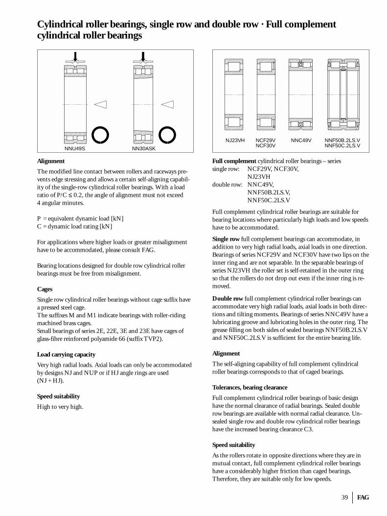
39 FAG
Cylindrical roller bearings, single row and double row · Full complement cylindrical roller bearings
Alignment
The modified line contact between rollers and raceways pre-vents edge stressing and allows a certain self-aligning capabil-ity of the single-row cylindrical roller bearings. With a load ratio of P/C ≤ 0.2, the angle of alignment must not exceed 4 angular minutes.
P = equivalent dynamic load [kN]C = dynamic load rating [kN]
For applications where higher loads or greater misalignmenthave to be accommodated, please consult FAG.
Bearing locations designed for double row cylindrical rollerbearings must be free from misalignment.
Cages
Single row cylindrical roller bearings without cage suffix havea pressed steel cage.The suffixes M and M1 indicate bearings with roller-ridingmachined brass cages.Small bearings of series 2E, 22E, 3E and 23E have cages ofglass-fibre reinforced polyamide 66 (suffix TVP2).
Load carrying capacity
Very high radial loads. Axial loads can only be accommodatedby designs NJ and NUP or if HJ angle rings are used (NJ + HJ).
Speed suitability
High to very high.
Full complement cylindrical roller bearings – seriessingle row: NCF29V, NCF30V,
NJ23VHdouble row: NNC49V,
NNF50B.2LS.V, NNF50C.2LS.V
Full complement cylindrical roller bearings are suitable forbearing locations where particularly high loads and low speedshave to be accommodated.
Single row full complement bearings can accommodate, inaddition to very high radial loads, axial loads in one direction.Bearings of series NCF29V and NCF30V have two lips on theinner ring and are not separable. In the separable bearings ofseries NJ23VH the roller set is self-retained in the outer ringso that the rollers do not drop out even if the inner ring is re-moved.
Double row full complement cylindrical roller bearings canaccommodate very high radial loads, axial loads in both direc-tions and tilting moments. Bearings of series NNC49V have alubricating groove and lubricating holes in the outer ring. Thegrease filling on both sides of sealed bearings NNF50B.2LS.Vand NNF50C.2LS.V is sufficient for the entire bearing life.
Alignment
The self-aligning capability of full complement cylindrical roller bearings corresponds to that of caged bearings.
Tolerances, bearing clearance
Full complement cylindrical roller bearings of basic designhave the normal clearance of radial bearings. Sealed doublerow bearings are available with normal radial clearance. Un-sealed single row and double row cylindrical roller bearingshave the increased bearing clearance C3.
Speed suitability
As the rollers rotate in opposite directions where they are inmutual contact, full complement cylindrical roller bearingshave a considerably higher friction than caged bearings.Therefore, they are suitable only for low speeds.
NNU49S NN30ASK
NJ23VH NCF29VNCF30V
NNF50B.2LS.VNNF50C.2LS.V
NNC49V
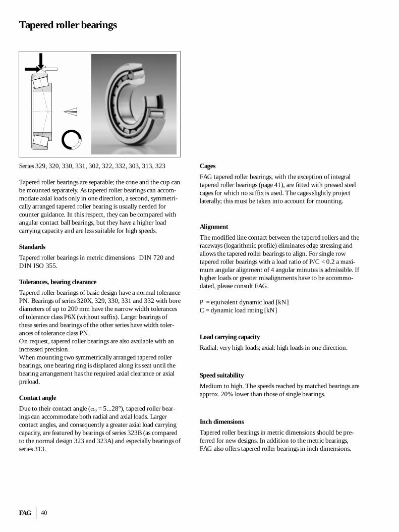
FAG 40
Tapered roller bearings
Series 329, 320, 330, 331, 302, 322, 332, 303, 313, 323
Tapered roller bearings are separable; the cone and the cup canbe mounted separately. As tapered roller bearings can accom-modate axial loads only in one direction, a second, symmetri-cally arranged tapered roller bearing is usually needed forcounter guidance. In this respect, they can be compared withangular contact ball bearings, but they have a higher loadcarrying capacity and are less suitable for high speeds.
Standards
Tapered roller bearings in metric dimensions DIN 720 andDIN ISO 355.
Tolerances, bearing clearance
Tapered roller bearings of basic design have a normal tolerancePN. Bearings of series 320X, 329, 330, 331 and 332 with borediameters of up to 200 mm have the narrow width tolerancesof tolerance class P6X (without suffix). Larger bearings of these series and bearings of the other series have width toler-ances of tolerance class PN.On request, tapered roller bearings are also available with anincreased precision.When mounting two symmetrically arranged tapered rollerbearings, one bearing ring is displaced along its seat until thebearing arrangement has the required axial clearance or axialpreload.
Contact angle
Due to their contact angle (�0 = 5...28°), tapered roller bear-ings can accommodate both radial and axial loads. Largercontact angles, and consequently a greater axial load carryingcapacity, are featured by bearings of series 323B (as comparedto the normal design 323 and 323A) and especially bearings ofseries 313.
Cages
FAG tapered roller bearings, with the exception of integral tapered roller bearings (page 41), are fitted with pressed steelcages for which no suffix is used. The cages slightly project laterally; this must be taken into account for mounting.
Alignment
The modified line contact between the tapered rollers and theraceways (logarithmic profile) eliminates edge stressing and allows the tapered roller bearings to align. For single rowtapered roller bearings with a load ratio of P/C < 0.2 a maxi-mum angular alignment of 4 angular minutes is admissible. Ifhigher loads or greater misalignments have to be accommo-dated, please consult FAG.
P = equivalent dynamic load [kN]C = dynamic load rating [kN]
Load carrying capacity
Radial: very high loads; axial: high loads in one direction.
Speed suitability
Medium to high. The speeds reached by matched bearings areapprox. 20% lower than those of single bearings.
Inch dimensions
Tapered roller bearings in metric dimensions should be pre-ferred for new designs. In addition to the metric bearings,FAG also offers tapered roller bearings in inch dimensions.
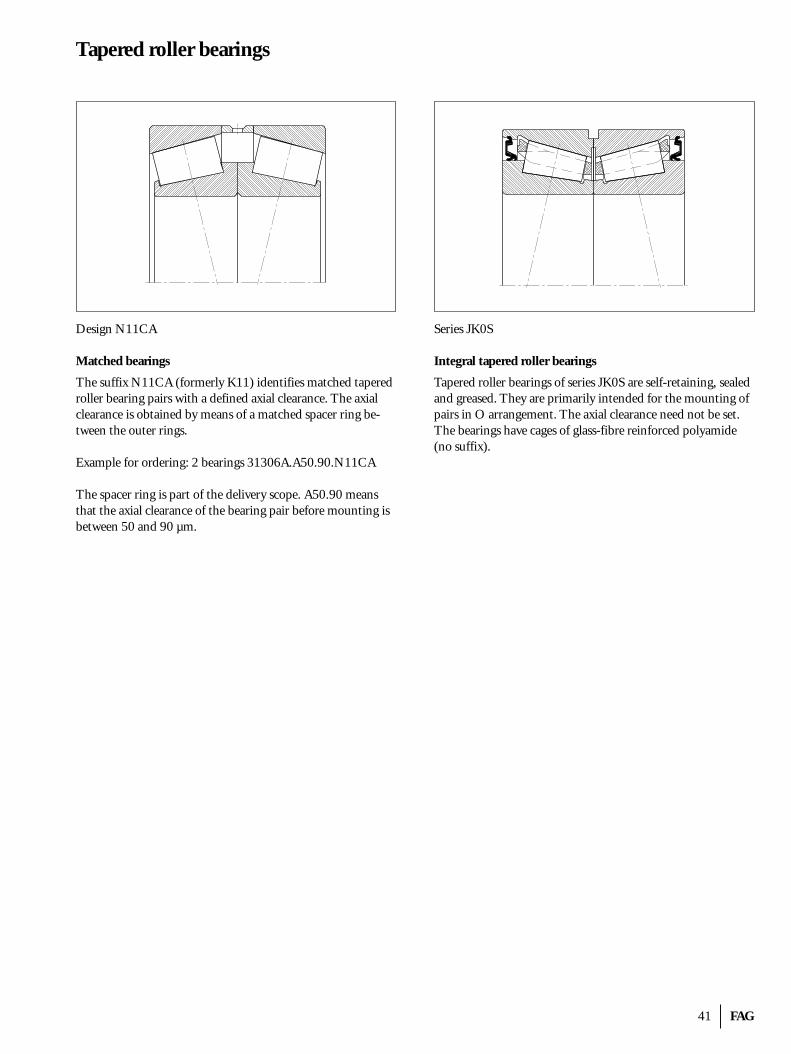
41 FAG
Tapered roller bearings
Design N11CA
Matched bearings
The suffix N11CA (formerly K11) identifies matched taperedroller bearing pairs with a defined axial clearance. The axialclearance is obtained by means of a matched spacer ring be-tween the outer rings.
Example for ordering: 2 bearings 31306A.A50.90.N11CA
The spacer ring is part of the delivery scope. A50.90 meansthat the axial clearance of the bearing pair before mounting isbetween 50 and 90 µm.
Series JK0S
Integral tapered roller bearings
Tapered roller bearings of series JK0S are self-retaining, sealedand greased. They are primarily intended for the mounting ofpairs in O arrangement. The axial clearance need not be set.The bearings have cages of glass-fibre reinforced polyamide(no suffix).
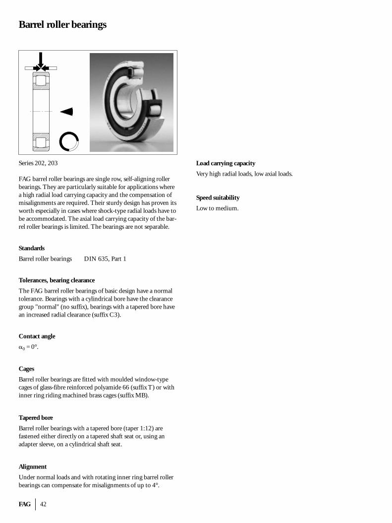
FAG 42
Barrel roller bearings
Series 202, 203
FAG barrel roller bearings are single row, self-aligning rollerbearings. They are particularly suitable for applications wherea high radial load carrying capacity and the compensation ofmisalignments are required. Their sturdy design has proven itsworth especially in cases where shock-type radial loads have tobe accommodated. The axial load carrying capacity of the bar-rel roller bearings is limited. The bearings are not separable.
Standards
Barrel roller bearings DIN 635, Part 1
Tolerances, bearing clearance
The FAG barrel roller bearings of basic design have a normaltolerance. Bearings with a cylindrical bore have the clearancegroup "normal" (no suffix), bearings with a tapered bore havean increased radial clearance (suffix C3).
Contact angle
�0 = 0°.
Cages
Barrel roller bearings are fitted with moulded window-type cages of glass-fibre reinforced polyamide 66 (suffix T) or withinner ring riding machined brass cages (suffix MB).
Tapered bore
Barrel roller bearings with a tapered bore (taper 1:12) arefastened either directly on a tapered shaft seat or, using an adapter sleeve, on a cylindrical shaft seat.
Alignment
Under normal loads and with rotating inner ring barrel rollerbearings can compensate for misalignments of up to 4°.
Load carrying capacity
Very high radial loads, low axial loads.
Speed suitability
Low to medium.
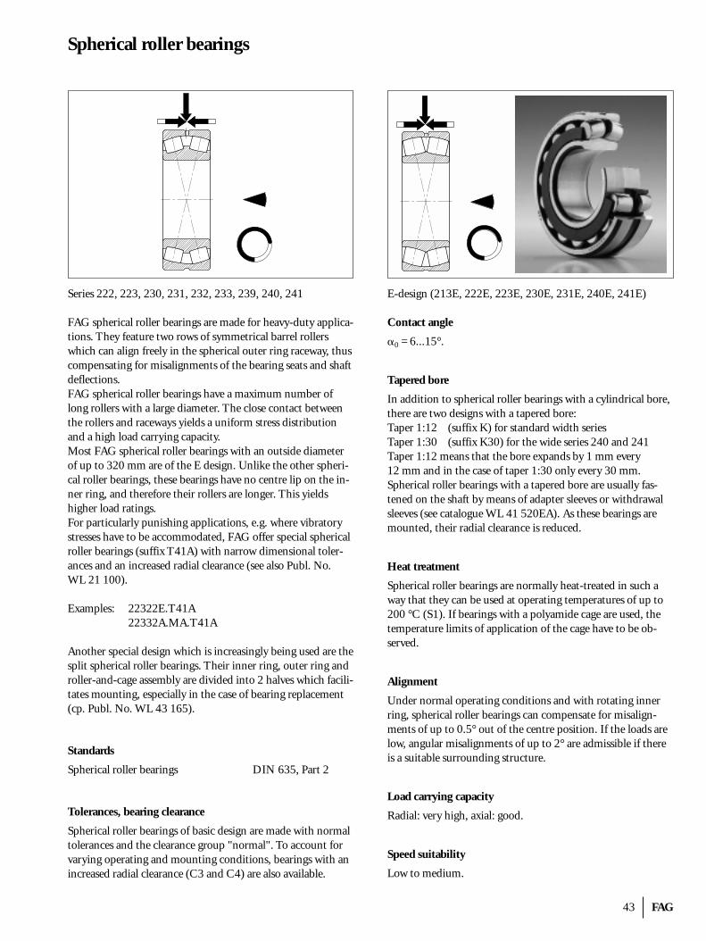
43 FAG
Spherical roller bearings
Series 222, 223, 230, 231, 232, 233, 239, 240, 241
FAG spherical roller bearings are made for heavy-duty applica-tions. They feature two rows of symmetrical barrel rollerswhich can align freely in the spherical outer ring raceway, thuscompensating for misalignments of the bearing seats and shaftdeflections.FAG spherical roller bearings have a maximum number oflong rollers with a large diameter. The close contact betweenthe rollers and raceways yields a uniform stress distributionand a high load carrying capacity.Most FAG spherical roller bearings with an outside diameterof up to 320 mm are of the E design. Unlike the other spheri-cal roller bearings, these bearings have no centre lip on the in-ner ring, and therefore their rollers are longer. This yields higher load ratings.For particularly punishing applications, e.g. where vibratorystresses have to be accommodated, FAG offer special sphericalroller bearings (suffix T41A) with narrow dimensional toler-ances and an increased radial clearance (see also Publ. No. WL 21 100).
Examples: 22322E.T41A22332A.MA.T41A
Another special design which is increasingly being used are thesplit spherical roller bearings. Their inner ring, outer ring androller-and-cage assembly are divided into 2 halves which facili-tates mounting, especially in the case of bearing replacement(cp. Publ. No. WL 43 165).
Standards
Spherical roller bearings DIN 635, Part 2
Tolerances, bearing clearance
Spherical roller bearings of basic design are made with normaltolerances and the clearance group "normal". To account forvarying operating and mounting conditions, bearings with anincreased radial clearance (C3 and C4) are also available.
E-design (213E, 222E, 223E, 230E, 231E, 240E, 241E)
Contact angle
�0 = 6...15°.
Tapered bore
In addition to spherical roller bearings with a cylindrical bore,there are two designs with a tapered bore:Taper 1:12 (suffix K) for standard width seriesTaper 1:30 (suffix K30) for the wide series 240 and 241Taper 1:12 means that the bore expands by 1 mm every 12 mm and in the case of taper 1:30 only every 30 mm.Spherical roller bearings with a tapered bore are usually fas-tened on the shaft by means of adapter sleeves or withdrawal sleeves (see catalogue WL 41 520EA). As these bearings aremounted, their radial clearance is reduced.
Heat treatment
Spherical roller bearings are normally heat-treated in such away that they can be used at operating temperatures of up to200 °C (S1). If bearings with a polyamide cage are used, thetemperature limits of application of the cage have to be ob-served.
Alignment
Under normal operating conditions and with rotating innerring, spherical roller bearings can compensate for misalign-ments of up to 0.5° out of the centre position. If the loads arelow, angular misalignments of up to 2° are admissible if thereis a suitable surrounding structure.
Load carrying capacity
Radial: very high, axial: good.
Speed suitability
Low to medium.
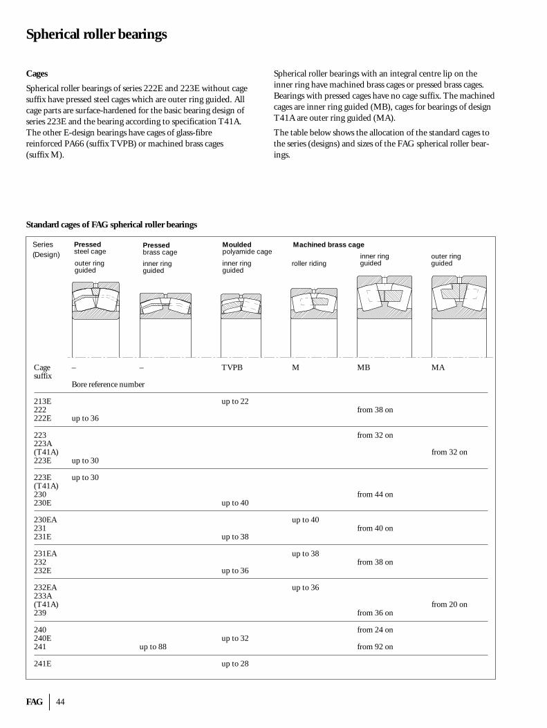
FAG 44
Spherical roller bearings
Cages
Spherical roller bearings of series 222E and 223E without cagesuffix have pressed steel cages which are outer ring guided. Allcage parts are surface-hardened for the basic bearing design ofseries 223E and the bearing according to specification T41A.The other E-design bearings have cages of glass-fibre reinforced PA66 (suffix TVPB) or machined brass cages (suffix M).
Spherical roller bearings with an integral centre lip on the inner ring have machined brass cages or pressed brass cages.Bearings with pressed cages have no cage suffix. The machinedcages are inner ring guided (MB), cages for bearings of designT41A are outer ring guided (MA).
The table below shows the allocation of the standard cages tothe series (designs) and sizes of the FAG spherical roller bear-ings.
Pressedsteel cage
Mouldedpolyamide cage
Machined brass cage
outer ringguided
inner ringguided
roller ridingouter ringguided
inner ringguided
Pressedbrass cage
inner ringguided
Series(Design)
Standard cages of FAG spherical roller bearings
Cage – – TVPB M MB MAsuffix
Bore reference number
213E up to 22222 from 38 on222E up to 36
223 from 32 on223A (T41A) from 32 on223E up to 30
223E up to 30(T41A)230 from 44 on230E up to 40
230EA up to 40231 from 40 on231E up to 38
231EA up to 38232 from 38 on232E up to 36
232EA up to 36233A (T41A) from 20 on239 from 36 on
240 from 24 on240E up to 32241 up to 88 from 92 on
241E up to 28
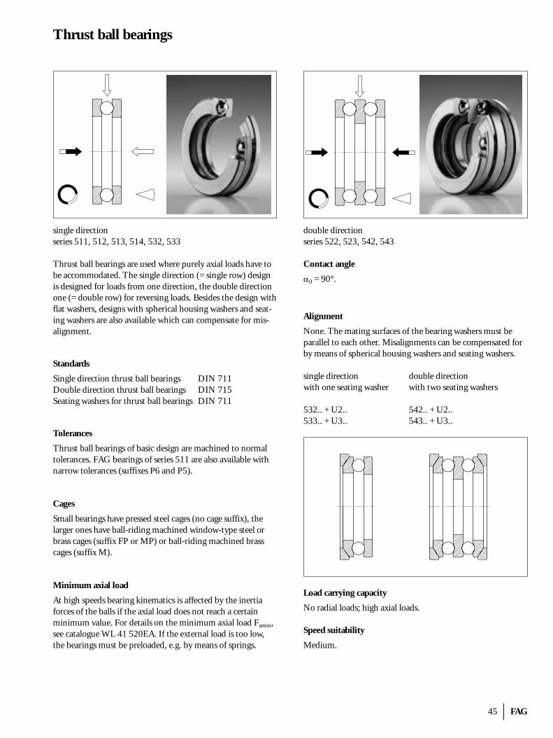
45 FAG
Thrust ball bearings
single directionseries 511, 512, 513, 514, 532, 533
Thrust ball bearings are used where purely axial loads have tobe accommodated. The single direction (= single row) designis designed for loads from one direction, the double directionone (= double row) for reversing loads. Besides the design withflat washers, designs with spherical housing washers and seat-ing washers are also available which can compensate for mis-alignment.
Standards
Single direction thrust ball bearings DIN 711Double direction thrust ball bearings DIN 715Seating washers for thrust ball bearings DIN 711
Tolerances
Thrust ball bearings of basic design are machined to normaltolerances. FAG bearings of series 511 are also available withnarrow tolerances (suffixes P6 and P5).
Cages
Small bearings have pressed steel cages (no cage suffix), the larger ones have ball-riding machined window-type steel orbrass cages (suffix FP or MP) or ball-riding machined brass cages (suffix M).
Minimum axial load
At high speeds bearing kinematics is affected by the inertiaforces of the balls if the axial load does not reach a certain minimum value. For details on the minimum axial load Famin,see catalogue WL 41 520EA. If the external load is too low,the bearings must be preloaded, e.g. by means of springs.
double directionseries 522, 523, 542, 543
Contact angle
�0 = 90°.
Alignment
None. The mating surfaces of the bearing washers must beparallel to each other. Misalignments can be compensated forby means of spherical housing washers and seating washers.
single direction double directionwith one seating washer with two seating washers
532.. + U2.. 542.. + U2..533.. + U3.. 543.. + U3..
Load carrying capacity
No radial loads; high axial loads.
Speed suitability
Medium.
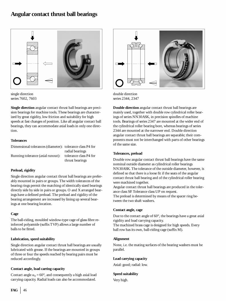
FAG 46
Angular contact thrust ball bearings
single directionseries 7602, 7603
Single direction angular contact thrust ball bearings are preci-sion bearings for machine tools. These bearings are character-ized by great rigidity, low friction and suitability for highspeeds at fast changes of position. Like all angular contact ballbearings, they can accommodate axial loads in only one direc-tion.
Tolerances
Dimensional tolerances (diameter): tolerance class P4 for radial bearings
Running tolerance (axial runout): tolerance class P4 for thrust bearings
Preload, rigidity
Single direction angular contact thrust ball bearings are prefer-ably mounted in pairs or groups. The width tolerances of thebearing rings permit the matching of identically sized bearingsdirectly side by side in pairs or groups. O and X arranged bear-ings have a defined preload. The preload and rigidity of thebearing arrangement are increased by lining up several bear-ings at one bearing location.
Cage
The ball-riding, moulded window-type cage of glass fibre re-inforced polyamide (suffix TVP) allows a large number ofballs to be fitted.
Lubrication, speed suitability
Single direction angular contact thrust ball bearings are usuallylubricated with grease. If the bearings are mounted in groupsof three or four the speeds reached by bearing pairs must bereduced accordingly.
Contact angle, load carring capacity
Contact angle �0 = 60°, and consequently a high axial loadcarrying capacity. Radial loads can also be accommodated.
double directionseries 2344, 2347
Double direction angular contact thrust ball bearings aremainly used, together with double row cylindrical roller bear-ings of series NN30ASK, in precision spindles of machinetools. Bearings of series 2347 are mounted at the wider end ofthe cylindrical roller bearing bore, whereas bearings of series2344 are mounted at the narrower end. Double direction angular contact thrust ball bearings are separable; their com-ponents must not be interchanged with parts of other bearingsof the same size.
Tolerances, preload
Double row angular contact thrust ball bearings have the samenominal outside diameter as cylindrical roller bearingsNN30ASK. The tolerance of the outside diameter, however, isdefined so that there is a loose fit if the seats of the angularcontact thrust ball bearing and of the cylindrical roller bearingwere machined together.Angular contact thrust ball bearings are produced in the toler-ance class SP. Tolerance class UP on request.The preload is determined by means of the spacer ring be-tween the two shaft washers.
Contact angle, cage
Due to the contact angle of 60°, the bearings have a great axialrigidity and load carrying capacity.The machined brass cage is designed for high speeds. Everyball row has its own, ball-riding cage (suffix M).
Alignment
None, i.e. the mating surfaces of the bearing washers must beparallel.
Load carrying capacity
Axial: good; radial: low.
Speed suitability
Very high.
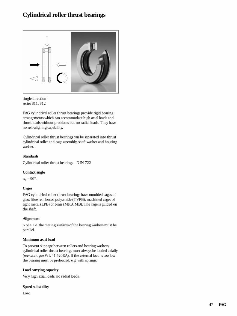
47 FAG
Cylindrical roller thrust bearings
single directionseries 811, 812
FAG cylindrical roller thrust bearings provide rigid bearing arrangements which can accommodate high axial loads andshock loads without problems but no radial loads. They haveno self-aligning capability.
Cylindrical roller thrust bearings can be separated into thrustcylindrical roller and cage assembly, shaft washer and housingwasher.
Standards
Cylindrical roller thrust bearings DIN 722
Contact angle
�0 = 90°.
Cages
FAG cylindrical roller thrust bearings have moulded cages ofglass fibre reinforced polyamide (TVPB), machined cages oflight metal (LPB) or brass (MPB, MB). The cage is guided onthe shaft.
Alignment
None, i.e. the mating surfaces of the bearing washers must beparallel.
Minimum axial load
To prevent slippage between rollers and bearing washers, cylindrical roller thrust bearings must always be loaded axially(see catalogue WL 41 520EA). If the external load is too lowthe bearing must be preloaded, e.g. with springs.
Load carrying capacity
Very high axial loads, no radial loads.
Speed suitability
Low.
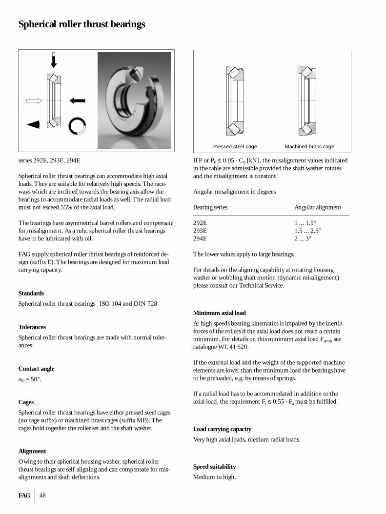
FAG 48
Spherical roller thrust bearings
series 292E, 293E, 294E
Spherical roller thrust bearings can accommodate high axialloads. They are suitable for relatively high speeds. The race-ways which are inclined towards the bearing axis allow thebearings to accommodate radial loads as well. The radial loadmust not exceed 55% of the axial load.
The bearings have asymmetrical barrel rollers and compensatefor misalignment. As a rule, spherical roller thrust bearingshave to be lubricated with oil.
FAG supply spherical roller thrust bearings of reinforced de-sign (suffix E). The bearings are designed for maximum loadcarrying capacity.
Standards
Spherical roller thrust bearings ISO 104 and DIN 728
Tolerances
Spherical roller thrust bearings are made with normal toler-ances.
Contact angle
�0 = 50°.
Cages
Spherical roller thrust bearings have either pressed steel cages(no cage suffix) or machined brass cages (suffix MB). The cages hold together the roller set and the shaft washer.
Alignment
Owing to their spherical housing washer, spherical rollerthrust bearings are self-aligning and can compensate for mis-alignments and shaft deflections.
If P or P0 ≤ 0.05 · C0 [kN], the misalignment values indicatedin the table are admissible provided the shaft washer rotatesand the misalignment is constant.
Angular misalignment in degrees
Bearing series Angular alignment
292E 1 ... 1.5°293E 1.5 ... 2.5°294E 2 ... 3°
The lower values apply to large bearings.
For details on the aligning capability at rotating housing washer or wobbling shaft motion (dynamic misalignment)please consult our Technical Service.
Minimum axial load
At high speeds bearing kinematics is impaired by the inertiaforces of the rollers if the axial load does not reach a certainminimum. For details on this minimum axial load Famin seecatalogue WL 41 520.
If the external load and the weight of the supported machineelements are lower than the minimum load the bearings haveto be preloaded, e.g. by means of springs.
If a radial load has to be accommodated in addition to the axial load, the requirement Fr ≤ 0.55 · Fa must be fulfilled.
Load carrying capacity
Very high axial loads, medium radial loads.
Speed suitability
Medium to high.
Pressed steel cage Machined brass cage
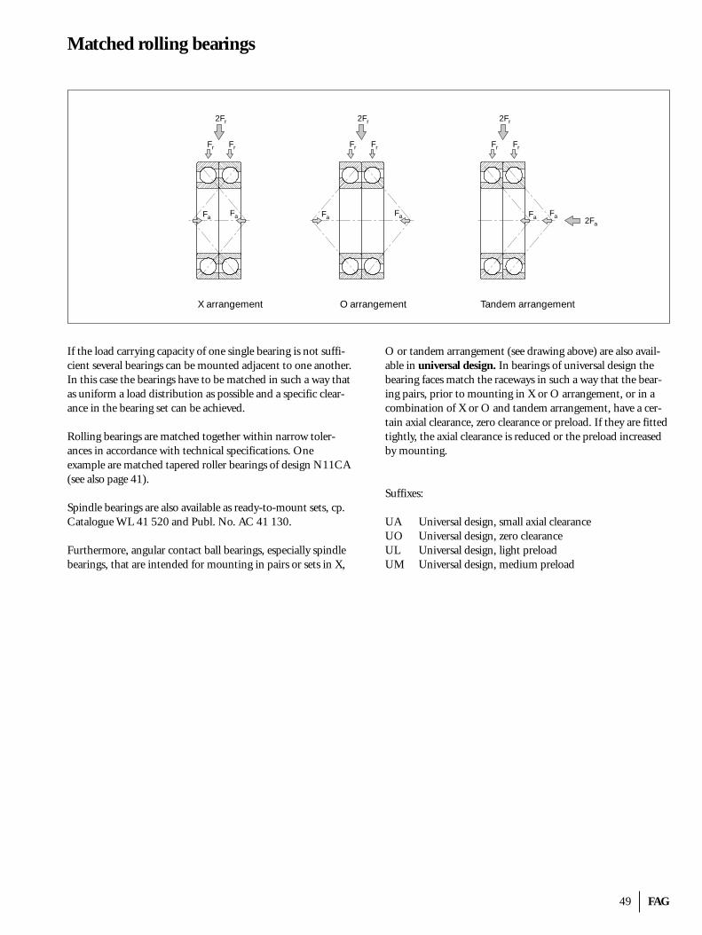
49 FAG
Matched rolling bearings
If the load carrying capacity of one single bearing is not suffi-cient several bearings can be mounted adjacent to one another.In this case the bearings have to be matched in such a way thatas uniform a load distribution as possible and a specific clear-ance in the bearing set can be achieved.
Rolling bearings are matched together within narrow toler-ances in accordance with technical specifications. One example are matched tapered roller bearings of design N11CA(see also page 41).
Spindle bearings are also available as ready-to-mount sets, cp.Catalogue WL 41 520 and Publ. No. AC 41 130.
Furthermore, angular contact ball bearings, especially spindlebearings, that are intended for mounting in pairs or sets in X,
O or tandem arrangement (see drawing above) are also avail-able in universal design. In bearings of universal design thebearing faces match the raceways in such a way that the bear-ing pairs, prior to mounting in X or O arrangement, or in acombination of X or O and tandem arrangement, have a cer-tain axial clearance, zero clearance or preload. If they are fittedtightly, the axial clearance is reduced or the preload increasedby mounting.
Suffixes:
UA Universal design, small axial clearanceUO Universal design, zero clearanceUL Universal design, light preloadUM Universal design, medium preload
X arrangement O arrangement Tandem arrangement
2Fr
FrFr
2Fr
FrFr
2Fr
FrFr
FaFa FaFa FaFa 2Fa
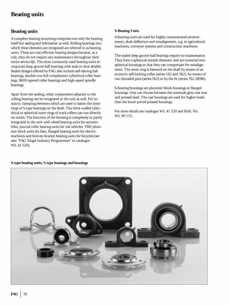
FAG 50
Bearing units
Bearing unitsA complete bearing mounting comprises not only the bearingitself but sealing and lubrication as well. Rolling bearings intowhich these elements are integrated are referred to as bearingunits. These are cost-efficient bearing designs because, as arule, they do not require any maintenance throughout theirentire service life. The most commonly used bearing units in-corporate deep groove ball bearings with seals or dust shields.Sealed designs offered by FAG also include self-alining ballbearings, double-row full complement cylindrical roller bear-ings, JK0S tapered roller bearings and high-speed spindlebearings.
Apart from the sealing, other components adjacent to the rolling bearing can be integrated in the unit as well. For in-stance, clamping elements which are used to fasten the innerrings of S-type bearings on the shaft. The thick-walled cylin-drical or spherical outer rings of track rollers can run directlyon tracks. The function of the housing is completely or partlyintegrated in the unit with wheel bearing units for automo-biles, journal roller bearing units for rail vehicles, VRE plum-mer block units for fans, flanged bearing units for electric machines and bottom bracket bearing units for bicycles (seealso "FAG Target Industry Programmes" in catalogue WL 41 520).
S-Bearing Units
S-bearing units are used for highly contaminated environ-ments, shaft deflection and misalignment, e.g. in agriculturalmachines, conveyor systems and construction machines.
The sealed deep groove ball bearings require no maintenance.They have a spherical outside diameter and are mounted intospherical housings so that they can compensate for misalign-ment. The inner ring is fastened on the shaft by means of aneccentric self-locking collar (series 162 and 362), by means oftwo threaded pins (series 562) or by the fit (series 762.2RSR).
S-bearing housings are plummer block housings or flangedhousings. One can choose between the materials grey-cast ironand pressed steel. The cast housings are used for higher loadsthan the lower priced pressed housings.
For more details see catalogue WL 41 520 and Publ. No. WL 90 115.
S-type bearing units, S-type bearings and housings
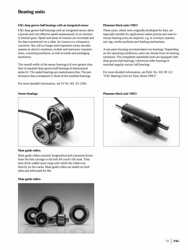
51 FAG
Bearing units
FAG deep groove ball bearings with an integrated sensor
FAG deep groove ball bearings with an integrated sensor allowa precise and cost-effective speed measurement in an extreme-ly limited space. Speed and sense of rotation are recoreded andthe data transmitted via a cable, for instance to a frequencyconverter. You will no longer need expensive rotary encodersystems in electric machines, mobile and stationary transmis-sions, conveying machines, as well as textile and packagingmachinery.
The overall width of the sensor bearings is 8 mm greater thanthat of standard deep groove ball bearings of dimensional series 62. The sealed bearings are maintenance-free. The per-formance data correspond to those of the standard bearings.
For more detailed information, see TI No. WL 43-1206.
Sensor bearings
Plummer block units VRE3
These units, which were originally developed for fans, are especially suitable for applications where precise and easy-to-mount bearing units are required, e.g. in conveyor systems,test rigs, textile machines and feeding mechanisms.
A one-piece housing accommodates two bearings. Dependingon the operating conditions, users can choose from six bearingvariations. The completely assembled units are equipped withdeep groove ball bearings, cylindrical roller bearings or matched angular contact ball bearings.
For more detailed information, see Publ. No. WL 90 121"FAG Bearing Units for Fans, Series VRE3".
Plummer block unit VRE3
Mast guide rollers
Mast guide rollers
Mast guide rollers transmit longitudinal and transverse forcesfrom the fork carriage to the fork lift truck's lift mast. Theyhave thick-walled outer rings with which the rollers rundirectly on the tracks. Mast guide rollers are sealed on both sides and lubricated for life.
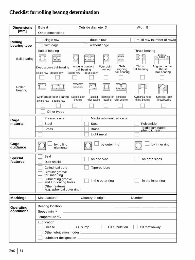
FAG 52
Checklist for rolling bearing determination
Dimensions[mm]
Rollingbearing type
Cagematerial
Cageguidance
Specialfeatures
Operatingconditions
Markings
Ball bearing
Rollerbearing
single row
with cage
double row
without cage
multi row (number of rows)
Radial bearing Thrust bearing
Bore d = Outside diameter D = Width B =
Other dimensions
Deep groove ball bearing Angular contactball bearing
Four pointbearing
Self-aligning
ball bearing
Thrustball bearing
Angular contactthrust
ball bearingsingle row double row single row double row
Cylindrical roller bearing Taperedroller bearing
Barrel rollerbearing
Sphericalroller bearing
Cylindrical rollerthrust bearing
Spherical rollerthrust bearing
Needle rollerbearingsingle row double row
Other types
Pressed cage Machined/moulded cage
Steel Steel
Brass Brass
Light metal
PolyamideTextile laminatedphenolic resin
by rollingelements
by outer ring by inner ring
Cylindrical bore
Seal
Dust shield
Circular groovefor snap ringLubricating grooveand lubricating holesOther features(e.g. spherical outer ring)
on one side on both sides
Tapered bore
in the outer ring in the inner ring
Manufacturer Country of origin Number
Bearing location
Speed min -1
Temperature °C
Lubrication
Grease
Other lubrication modes
Lubricant designation
Oil sump Oil circulation Oil throwaway
53 FAG
Index
Additives 9, 14, 17Adjusted bearing arrangement/Adjusting 31Adjusted rating life calculation 12Ageing 17Alignment 27Angular contact bearings 4Arcanol (FAG rolling bearing greases) 17, 18Attainable life Lna, Lhna 12Axial clearance 24
Ball bearings 4Base oil 13, 17Basic a23II factor 13Bearing clearance 24Bearing life 10Bearing rings 6Boundary lubrication 19
Cages 6Changing operating conditions 12Circumferential load 28Cleanliness factor s 13, 16Combined load 8Consistency 17Contact angle 4Contact lines 4Contamination factor V 14Counter guidance 32Curvature ratio 8
Dimensioning 9Dry lubricants 17Dynamic load rating C 8Dynamic viscosity 20Dynamically stressed rolling bearings 10
EP additives 17Equivalent dynamic load P 10Equivalent static load P0 9
Factor a1 12Factor a23 (life adjustment factor) 12Fatigue life 10Filtration ratio 16Fits 28Floating bearing arrangement 31Floating bearing 29Full fluid film lubrication 19
Grease lubrication 17Grease life 19
High temperature suitability 23
Index of dynamic stressing fL 11Index of static stressing fs 9
Kinematic viscosity 20Kinematically permissible speed 22
Life 10Life exponent p 11Limiting speed 22Lithium soap base greases 19Load angle 8Load rating 8Locating bearing/floating bearing arrangement 29Locating bearing 29Lubricating conditions 19Lubricating greases 19Lubricating oils 19Lubrication interval 19
Machined cages 6Matched rolling bearings 49Mineral oils 19Mixed lubrication 19Modified life 12Moulded cages 7Mountingt and dismounting 28
Nominal rating life 11Nominal viscosity 20Non-rubbing seals 21
O arrangement 29, 31, 49Oil cleanliness classes 15Oil lubrication 17Operating clearance 25Operating viscosity � 13, 19
Penetration -> ConsistencyPoint load 28Polyamide cages 7Precision bearings/Precision design 26Pressed cages 6Pressure cone apex 4
Radial bearings 4Radial clearance/Radial clearance group 24Rated viscosity �1 13, 19Reference speed 22Relubrication interval 19Roller bearings 4Rolling bearing catalogue on CD-ROM 2Rolling Bearing Learning System W.L.S. 2Rolling elements 4, 5Rubbing seals 21
FAG 54
Sealing/Seals 21Self-aligning bearings 27Separable bearings 6Service life 9Speed factor fn 11Speed index n · dm 19Speed suitability 22Spread 31Static load rating C0 8Statically stressed rolling bearings 9Stress index fs* 14Synthetic lubricants/Synthetic oils 19
Tandem arrangement 32, 49Thermally permissible operating speed 22Thickener 20Thrust bearings 4Tolerance classes 26Type of guidance (cage) 7
Universal design -> Matched rolling bearings
Value K 13Varying loads and speeds 10Viscosity 20Viscosity classification 20Viscosity ratio � 12, 20Viscosity-temperature behaviour (V-T behaviour) 20
Wear 9Worked penetration -> Consistency
X arrangement 29, 31, 49
Index
FAG OEM und Handel AGA company of the FAG Kugelfischer Group
Postfach 12 60 · D-97419 SchweinfurtTelephone (09721) 91 37 07 · Telefax (09721) 91 31 33http://www.fag.de
FAG Rolling BearingsFundamentals · Types · Designs
Every care has been taken to ensure the correctness of the information contained in this publication but no liability can be accepted for any errors or omissions. We reserve the right to make changes in the interest of technical progress.
© by FAG 1999. This publication or parts thereof may not be reproduced without our permission.
TI No. WL 43-1190 EA/94/10/99 · Printed in Germany by Weppert GmbH & Co. KG, Schweinfurt