Embed Size (px)
Citation preview
Procedia Materials Science 3 ( 2014 ) 447 – 453
Available online at www.sciencedirect.com
2211-8128 © 2014 Published by Elsevier Ltd. This is an open access article under the CC BY-NC-ND license (http://creativecommons.org/licenses/by-nc-nd/3.0/).Selection and peer-review under responsibility of the Norwegian University of Science and Technology (NTNU), Department of Structural Engineeringdoi: 10.1016/j.mspro.2014.06.075
ScienceDirect
20th European Conference on Fracture (ECF20)
Failure Analysis on Fracture of a S135 Drill Pipe Han Yana, Zhao Xuehua, Bai Zhenquana, Yin Chengxiana
aCNPC Tulular Goods Research Institute,89 Jinye Second Road, Xi’an,710017, Shaanxi Province, China
Abstract
The fracture of drill pipe is mainly controlled by the material of drill pipe and environment of operation, which maybe induces huge loss of economy and society. A fractured 3 1/2″ S135 drill pipe was analyzed through physical and chemical properties, Scanning Electron Microscope (SEM) and Energy Dispersive Spectrometer (EDS) method. Additionally, a series research about sulfur resistance of S135 was also estimated by sulfide stress cracking test and hydrogen-induced cracking test. The results showed that the failure of the drill pipe was belong to sulfide stress corrosion cracking. High H2S content condition and the material with high strength leaded to the final rupture of the drill pipe. The application of drill pipe with high strength was also proposed on the basis of above results and discussion. © 2014 The Authors. Published by Elsevier Ltd. Selection and peer-review under responsibility of the Norwegian University of Science and Technology (NTNU), Department of Structural Engineering.
Keywords: Drill pipe; Fracture; Sulfide stress corrosion cracking; Failure analysis
1. Background
The fractured drill pipe was used in Tahe Oilfield in China Petroleum Xinjiang Petrochemical Co., Ltd.. The depth of the well was 6235m. It was found that the weight of string hanging decreased sharply from 96 t to 34 t during the cement squeeze process of well repair operation, and the 174th drill pipe was found fractured when it was left from the well, the depth was 1665.93m. The specification of fractured drill pipe was 3 1/2’’S135, the wall thickness was 9.94mm, and the service time was approximately 210.5 hours in this well totally.
In order to ascertain the reasons for the failure, and prevent such accident from happening again, a complete failure analysis of the fractured drill pipe was made in this paper.
© 2014 Published by Elsevier Ltd. This is an open access article under the CC BY-NC-ND license (http://creativecommons.org/licenses/by-nc-nd/3.0/).Selection and peer-review under responsibility of the Norwegian University of Science and Technology (NTNU), Department of Structural Engineering
448 Han Yan et al. / Procedia Materials Science 3 ( 2014 ) 447 – 453
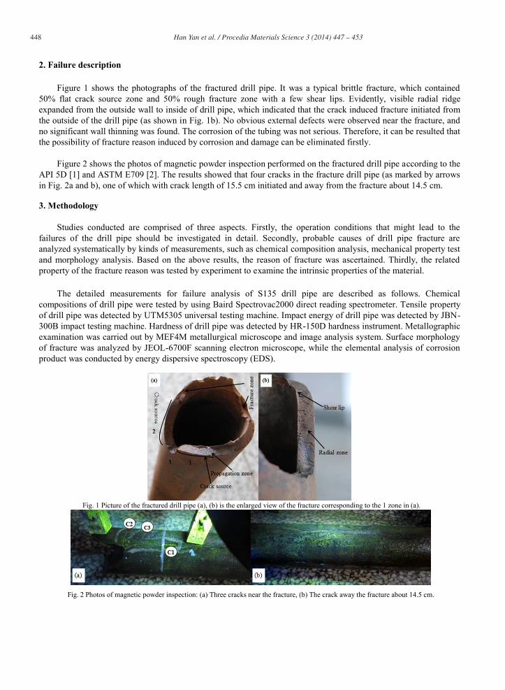
2. Failure description
Figure 1 shows the photographs of the fractured drill pipe. It was a typical brittle fracture, which contained 50% flat crack source zone and 50% rough fracture zone with a few shear lips. Evidently, visible radial ridge expanded from the outside wall to inside of drill pipe, which indicated that the crack induced fracture initiated from the outside of the drill pipe (as shown in Fig. 1b). No obvious external defects were observed near the fracture, and no significant wall thinning was found. The corrosion of the tubing was not serious. Therefore, it can be resulted that the possibility of fracture reason induced by corrosion and damage can be eliminated firstly.
Figure 2 shows the photos of magnetic powder inspection performed on the fractured drill pipe according to the
API 5D [1] and ASTM E709 [2]. The results showed that four cracks in the fracture drill pipe (as marked by arrows in Fig. 2a and b), one of which with crack length of 15.5 cm initiated and away from the fracture about 14.5 cm.
3. Methodology
Studies conducted are comprised of three aspects. Firstly, the operation conditions that might lead to the failures of the drill pipe should be investigated in detail. Secondly, probable causes of drill pipe fracture are analyzed systematically by kinds of measurements, such as chemical composition analysis, mechanical property test and morphology analysis. Based on the above results, the reason of fracture was ascertained. Thirdly, the related property of the fracture reason was tested by experiment to examine the intrinsic properties of the material.
The detailed measurements for failure analysis of S135 drill pipe are described as follows. Chemical
compositions of drill pipe were tested by using Baird Spectrovac2000 direct reading spectrometer. Tensile property of drill pipe was detected by UTM5305 universal testing machine. Impact energy of drill pipe was detected by JBN-300B impact testing machine. Hardness of drill pipe was detected by HR-150D hardness instrument. Metallographic examination was carried out by MEF4M metallurgical microscope and image analysis system. Surface morphology of fracture was analyzed by JEOL-6700F scanning electron microscope, while the elemental analysis of corrosion product was conducted by energy dispersive spectroscopy (EDS).
Fig. 1 Picture of the fractured drill pipe (a), (b) is the enlarged view of the fracture corresponding to the 1 zone in (a).
Fig. 2 Photos of magnetic powder inspection: (a) Three cracks near the fracture, (b) The crack away the fracture about 14.5 cm.
449 Han Yan et al. / Procedia Materials Science 3 ( 2014 ) 447 – 453
4. Results and discussions
The macro morphology of the fracture showed that the no obvious external defects near the fracture, corrosion pit and wall thinning were observed (as shown in Fig. 1). It meant that the foreign object damage maybe has little effect on the fracture of drill pipe. Based on the results of Fig. 2, it was found that the crack initiation was random, which indicated that the fracture may be related to the material defects of drill pipe or operation environment. Therefore, the operation conditions and the material properties that maybe lead to the failures of the drill pipe were investigated in detail. As the intrinsic property, the chemical compositions, mechanical properties and metallographic structure of the drill pipe was analyzed to check whether the material defects induced the fracture failure. Before test, the operation condition was reviewed to find out the influence factors came from the operation environment.
4.1 Review of the operation condition
According to the well data the depth of the well is 6235 m, pressure of the bottom hole is 68 MPa, temperature of the bottom hole is approximately 140oC. On this basis, the calculated temperature of the fractured position is about 38oC, and the pressure is about 17.8 MPa. The well is located in the well area with high hydrogen sulfide content of over 4000 mg/m3, which belongs to high sulfur content oil according to gas reservoir classification determination standard SY / T 6168-1995[3]. It has been reported that high-strength steel has high sensitive to sulfide stress cracking at low temperature [4], thus, S135 drill pipe has a high risk to sulfide stress cracking in this well. Therefore, the sulfide stress cracking is a very possibility that caused the fracture of the drill pipe.
4.2 Chemical Compositions
The specimen sampled from the fracture of the drill pipe was used to analyze the chemical compositions. The contents of eleven chemical elements were analyzed, as shown in Table 1. The results showed that the chemical compositions are in accordance with the technical requirements of the product standard.
Table 1 Chemical composition results (wt.%).
Elements C Si Mn P S Cr Mo Ni V Ti Cu
Drill pipe 0.26 0.21 0.77 0.011 0.0024 0.88 0.35 0.021 0.0058 0.0074 0.075
API Spec 5D / / / ≤0.03 ≤0.03 / / / / / /
4.3 Mechanical properties
The specimens used to perform tensile test, impact test and hardness test were all sampled from fractured drill pipe. The tensile test and impact test were performed according to the ASTM A370-2010 [5]. The sample size tested and results are shown in Table 2. The results showed that tensile property and impact energy of drill pipe were in accordance with requirements of API Spec 5D. The hardness test was carried out according to ASTM E18-2008 [6]. The schematic of test positions is shown in Fig. 3, results of which are showed in Table 3. It is evidently that the drill pipe had a high hardness, which was larger than 30 HRC. Table 2 Test results of mechanical properties
Items Results of tensile test (longitudinal) Results of impact test (longitudinal, 21oC)
Rm (MPa) Rt0.7 (MPa) A (%) Sample size (mm) CVN (J)
Drill pipe
Sample 1 1140 1060 18.5
7.5×10×55
85.0
Sample 2 1150 1090 18.5 53.0
Sample 3 1150 1070 18.5 56.0
API Spec 5D ≥1000 931 1138 ≥12.5 ≥43.2*
Note: The value for 7.5×10×55mm sample.
450 Han Yan et al. / Procedia Materials Science 3 ( 2014 ) 447 – 453
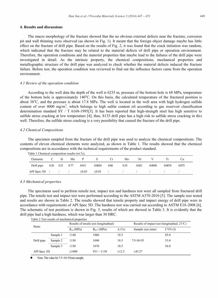
Fig. 3 Positions of the hardness test.
Table 3 Test results of hardness (HRC) Position 1 2 3 4 5 6 7 8 9 10 11 12
Results 20.7 35.9 35.1 37.3 33.2 36.6 36.6 36.2 35.3 35.5 32.4 35.2
API Spec 5D -
4.4 Metallographic examination
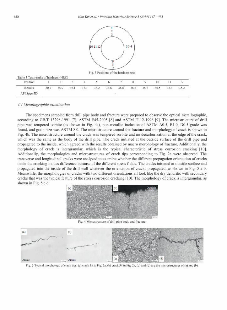
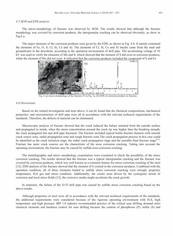
The specimens sampled from drill pipe body and fracture were prepared to observe the optical metallographic, according to GB/T 13298-1991 [7], ASTM E45-2005 [8] and ASTM E112-1996 [9]. The microstructure of drill pipe was tempered sorbite (as shown in Fig. 4a), non-metallic inclusion of ASTM A0.5, B1.0, D0.5 grade was found, and grain size was ASTM 8.0. The microstructure around the fracture and morphology of crack is shown in Fig. 4b. The microstructure around the crack was tempered sorbite and no decarburization at the edge of the crack, which was the same as the body of the drill pipe. The crack initiated at the outside surface of the drill pipe and propagated to the inside, which agreed with the results obtained by macro morphology of fracture. Additionally, the morphology of crack is intergranular, which is the typical characteristic of stress corrosion cracking [10]. Additionally, the morphologies and microstructures of crack tips corresponding to Fig. 2a were observed. The transverse and longitudinal cracks were analyzed to examine whether the different propagation orientation of cracks made the cracking modes difference because of the different stress fields. The cracks initiated at outside surface and propagated into the inside of the drill wall whatever the orientation of cracks propagated, as shown in Fig. 5 a b. Meanwhile, the morphologies of cracks with two different orientations all look like the dry dendritic with secondary cracks that was the typical feature of the stress corrosion cracking [10]. The morphology of crack is intergranular, as shown in Fig. 5 c d.
Fig. 4 Microstructure of drill pipe body and fracture.
Fig. 5 Typical morphology of crack tips: (a) crack 1# in Fig. 2a, (b) crack 3# in Fig. 2a, (c) and (d) are the microstructures of (a) and (b).
451 Han Yan et al. / Procedia Materials Science 3 ( 2014 ) 447 – 453
4.5 SEM and EDS analysis
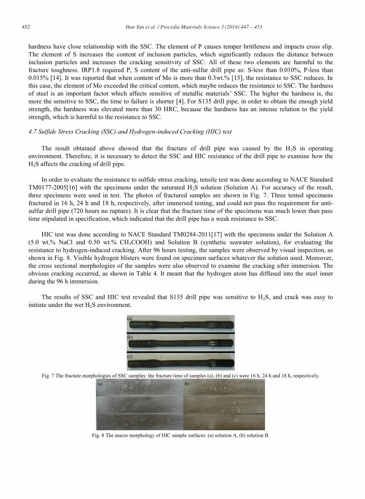
The micro-morphology of fracture was observed by SEM. The results showed that although the fracture morphology was covered by corrosion products, the intergranular cracking can be observed obviously, as show in Fig.6 a.
The major elements of the corrosion products were given by the EDS, as shown in Fig. 6 b. It mainly contained
the elements of Fe, O, S, Cl, Si, Ca and Al. The elements of Cl, Si, Ca and Al maybe came from the mud and groundwater in the downhole, according to the operation environment of drill pipe. The accelerating voltage of 10 kV was used to verify the elements of Mo and S, which showed that the element of S did exist in corrosion products, while the element of Mo did not exist. It indicated that the corrosion products included the compound of S and Fe.
Fig. 6 (a) micro-morphology of the fracture #3 in Fig. 1a, (b) EDS of corrosion product on fracture.
4.6 Discussions
Based on the related investigation and tests above, it can be found that the chemical compositions, mechanical properties, and microstructure of drill pipe were all in accordance with the relevant technical requirements of the standards. Therefore, the defects of material can be eliminated.
Macroscopic analysis of fracture showed that the crack induced the failure initiated from the outside surface
and propagated to inside, when the stress concentration around the crack tip was higher than the breaking stength, the crack propagated fast and drill pipe fractured. The fracture included typical brittle fracture features with smooth crack source zone, radial propagation zone and rough fracture zone.The crack propagation process in this case could be identified as the crack initiation stage, the stable crack propagation stage and the unstable final fracture stage[11]. Fracture has more crack sources are the charactristic of the sress corrosion cracking. Taking into account the operating environment, the fracture may be caused by sulfide sress corrosion cracking.
The metallographic and micro morphology examination were examined to check the possibility of the stress
corrosion cracking. The results showed that the fracture was a typical intergranular cracking and the fracture was covered by corrosion products, which was well known as a common feature for stress corrosion cracking of the steel [12]. EDS analysis of the fracture showed that the element of S existed in the corrosion products. Combined with the operation condition, all of three elements leaded to sulfide stress corrosion cracking were enough: propriety temperature, H2S gas and stress condition. Additionally, the cracks were driven by the synergistic action of corrosion and local stress fields [13], the corrosive media might accelerate the crack growth.
In summary, the failure of the S135 drill pipe was caused by sulfide stress corrosion cracking based on the
above results. Although properties of steel were all in accordance with the relevant technical requirements of the standards,
the additional requirements were considered because of the rigorous operating environment with H2S, high temperature and high pressure. IRP 1.8 industry recommended practice of the critical sour drilling demand strict chemical elements and hardness control for sour drilling because the content of phosphorus (P), sulfur (S) and
(a) (b)
452 Han Yan et al. / Procedia Materials Science 3 ( 2014 ) 447 – 453
hardness have close relationship with the SSC. The element of P causes temper brittleness and impacts cross slip. The element of S increases the content of inclusion particles, which significantly reduces the distance between inclusion particles and increases the cracking sensitivity of SSC. All of these two elements are harmful to the fracture toughness. IRP1.8 required P, S content of the anti-sulfur drill pipe as: S-less than 0.010%, P-less than 0.015% [14]. It was reported that when content of Mo is more than 0.3wt.% [15], the resistance to SSC reduces. In this case, the element of Mo exceeded the critical content, which maybe reduces the resistance to SSC. The hardness of steel is an important factor which affects sensitive of metallic materials’ SSC. The higher the hardness is, the more the sensitive to SSC, the time to failure is shorter [4]. For S135 drill pipe, in order to obtain the enough yield strength, the hardness was elevated more than 30 HRC, because the hardness has an intense relation to the yield strength, which is harmful to the resistance to SSC.
4.7 Sulfide Stress Cracking (SSC) and Hydrogen-induced Cracking (HIC) test
The result obtained above showed that the fracture of drill pipe was caused by the H2S in operating environment. Therefore, it is necessary to detect the SSC and HIC resistance of the drill pipe to examine how the H2S affects the cracking of drill pipe.
In order to evaluate the resistance to sulfide stress cracking, tensile test was done according to NACE Standard
TM0177-2005[16] with the specimens under the saturated H2S solution (Solution A). For accuracy of the result, three specimens were used in test. The photos of fractured samples are shown in Fig. 7. Three tested specimens fractured in 16 h, 24 h and 18 h, respectively, after immersed testing, and could not pass the requirement for anti-sulfur drill pipe (720 hours no rupture). It is clear that the fracture time of the specimens was much lower than pass time stipulated in specification, which indicated that the drill pipe has a weak resistance to SSC.
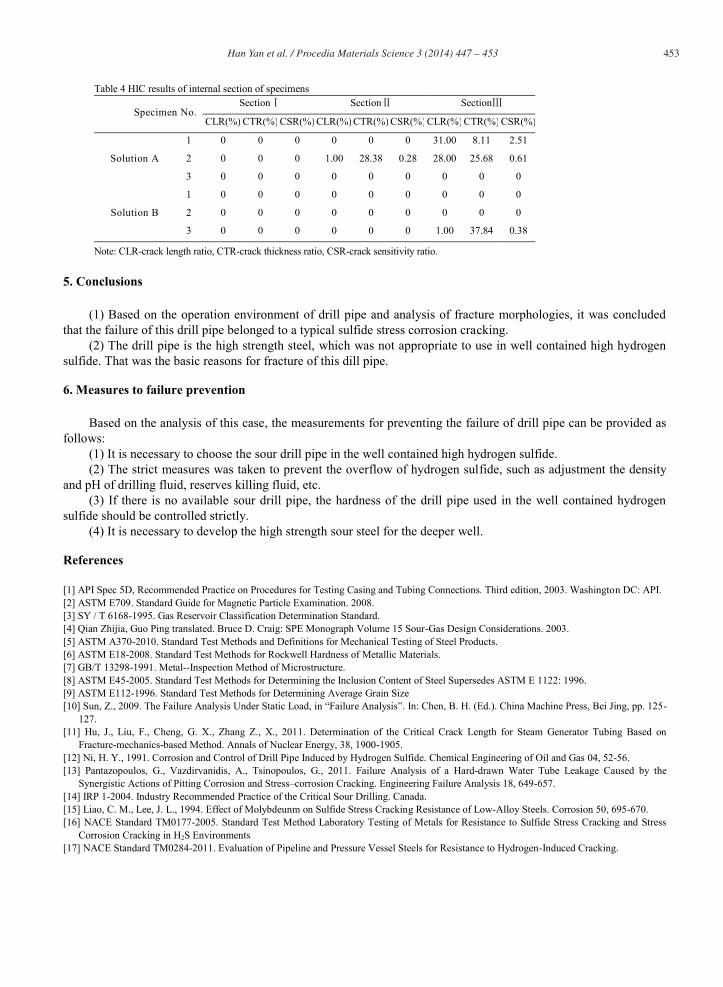
HIC test was done according to NACE Standard TM0284-2011[17] with the specimens under the Solution A
(5.0 wt.% NaCl and 0.50 wt.% CH3COOH) and Solution B (synthetic seawater solution), for evaluating the resistance to hydrogen-induced cracking. After 96 hours testing, the samples were observed by visual inspection, as shown in Fig. 8. Visible hydrogen blisters were found on specimen surfaces whatever the solution used. Moreover, the cross sectional morphologies of the samples were also observed to examine the cracking after immersion. The obvious cracking occurred, as shown in Table 4. It meant that the hydrogen atom has diffused into the steel inner during the 96 h immersion.
The results of SSC and HIC test revealed that S135 drill pipe was sensitive to H2S, and crack was easy to
initiate under the wet H2S environment.
Fig. 7 The fracture morphologies of SSC samples: the fracture time of samples (a), (b) and (c) were 16 h, 24 h and 18 h, respectively.
Fig. 8 The macro morphology of HIC sample surfaces: (a) solution A, (b) solution B.
453 Han Yan et al. / Procedia Materials Science 3 ( 2014 ) 447 – 453
Table 4 HIC results of internal section of specimens
Specimen No. Section Section Section
CLR(%) CTR(%) CSR(%) CLR(%) CTR(%) CSR(%) CLR(%) CTR(%) CSR(%)
Solution A
1 0 0 0 0 0 0 31.00 8.11 2.51
2 0 0 0 1.00 28.38 0.28 28.00 25.68 0.61
3 0 0 0 0 0 0 0 0 0
Solution B
1 0 0 0 0 0 0 0 0 0
2 0 0 0 0 0 0 0 0 0
3 0 0 0 0 0 0 1.00 37.84 0.38
Note: CLR-crack length ratio, CTR-crack thickness ratio, CSR-crack sensitivity ratio.
5. Conclusions
(1) Based on the operation environment of drill pipe and analysis of fracture morphologies, it was concluded that the failure of this drill pipe belonged to a typical sulfide stress corrosion cracking.
(2) The drill pipe is the high strength steel, which was not appropriate to use in well contained high hydrogen sulfide. That was the basic reasons for fracture of this dill pipe.
6. Measures to failure prevention
Based on the analysis of this case, the measurements for preventing the failure of drill pipe can be provided as follows:
(1) It is necessary to choose the sour drill pipe in the well contained high hydrogen sulfide. (2) The strict measures was taken to prevent the overflow of hydrogen sulfide, such as adjustment the density
and pH of drilling fluid, reserves killing fluid, etc. (3) If there is no available sour drill pipe, the hardness of the drill pipe used in the well contained hydrogen
sulfide should be controlled strictly. (4) It is necessary to develop the high strength sour steel for the deeper well.
References
[1] API Spec 5D, Recommended Practice on Procedures for Testing Casing and Tubing Connections. Third edition, 2003. Washington DC: API. [2] ASTM E709. Standard Guide for Magnetic Particle Examination. 2008. [3] SY / T 6168-1995. Gas Reservoir Classification Determination Standard. [4] Qian Zhijia, Guo Ping translated. Bruce D. Craig: SPE Monograph Volume 15 Sour-Gas Design Considerations. 2003. [5] ASTM A370-2010. Standard Test Methods and Definitions for Mechanical Testing of Steel Products. [6] ASTM E18-2008. Standard Test Methods for Rockwell Hardness of Metallic Materials. [7] GB/T 13298-1991. Metal--Inspection Method of Microstructure. [8] ASTM E45-2005. Standard Test Methods for Determining the Inclusion Content of Steel Supersedes ASTM E 1122: 1996. [9] ASTM E112-1996. Standard Test Methods for Determining Average Grain Size [10] Sun, Z., 2009. The Failure Analysis Under Static Load, in “Failure Analysis”. In: Chen, B. H. (Ed.). China Machine Press, Bei Jing, pp. 125-
127. [11] Hu, J., Liu, F., Cheng, G. X., Zhang Z., X., 2011. Determination of the Critical Crack Length for Steam Generator Tubing Based on
Fracture-mechanics-based Method. Annals of Nuclear Energy, 38, 1900-1905. [12] Ni, H. Y., 1991. Corrosion and Control of Drill Pipe Induced by Hydrogen Sulfide. Chemical Engineering of Oil and Gas 04, 52-56. [13] Pantazopoulos, G., Vazdirvanidis, A., Tsinopoulos, G., 2011. Failure Analysis of a Hard-drawn Water Tube Leakage Caused by the
Synergistic Actions of Pitting Corrosion and Stress–corrosion Cracking. Engineering Failure Analysis 18, 649-657. [14] IRP 1-2004. Industry Recommended Practice of the Critical Sour Drilling. Canada. [15] Liao, C. M., Lee, J. L., 1994. Effect of Molybdeunm on Sulfide Stress Cracking Resistance of Low-Alloy Steels. Corrosion 50, 695-670. [16] NACE Standard TM0177-2005. Standard Test Method Laboratory Testing of Metals for Resistance to Sulfide Stress Cracking and Stress
Corrosion Cracking in H2S Environments [17] NACE Standard TM0284-2011. Evaluation of Pipeline and Pressure Vessel Steels for Resistance to Hydrogen-Induced Cracking.