Embed Size (px)
Citation preview
PHYSICAL REVIEW A 83, 042319 (2011)
Fast and robust quantum computation with ionic Wigner crystals
J. D. Baltrusch,1,2,3 A. Negretti,1 J. M. Taylor,4 and T. Calarco1,5
1Institute for Quantum Information Processing, University of Ulm, Albert-Einstein-Allee 11, D-89069 Ulm, Germany2Grup d’Optica, Edifici CC, Universitat Autonoma de Barcelona (UAB), E-08193 Bellaterra (Barcelona), Spain
3Theoretische Physik, Universitat des Saarlandes, D-66041 Saarbrucken, Germany4Joint Quantum Institute and the National Institute of Standards and Technology, College Park, Maryland 20742, USA
5Department of Physics, Harvard University, and ITAMP, Cambridge, Massachusetts 02138, USA(Received 25 November 2010; revised manuscript received 16 February 2011; published 15 April 2011)
We present a detailed analysis of the modulated-carrier quantum phase gate implemented with Wigner crystalsof ions confined in Penning traps. We elaborate on a recent scheme, proposed by two of the authors, to engineertwo-body interactions between ions in such crystals. We analyze the situation in which the cyclotron (ωc) and thecrystal rotation (ωr ) frequencies do not fulfill the condition ωc = 2ωr . It is shown that even in the presence of themagnetic field in the rotating frame the many-body (classical) Hamiltonian describing small oscillations fromthe ion equilibrium positions can be recast in canonical form. As a consequence, we are able to demonstrate thatfast and robust two-qubit gates are achievable within the current experimental limitations. Moreover, we describea realization of the state-dependent sign-changing dipole forces needed to realize the investigated quantumcomputing scheme.
DOI: 10.1103/PhysRevA.83.042319 PACS number(s): 03.67.Lx, 37.10.Ty, 37.10.De, 45.50.−j
I. INTRODUCTION
Despite the huge experimental progress to cool, trap, andmanipulate single particles such as atoms and molecules at thequantum level, the way to build up a quantum computinghardware working with several hundreds of quantum bits(qubits) in a coherent and controllable manner is still long. Bymeans of quantum optimal control techniques it is possible,at least theoretically, to perform one- and two-qubit quantumgates with fidelities above the demanding thresholds of fault-tolerant quantum computation [1–9]. These thresholds fix anerror between 0.01% to fractions of a percent [10,11]. Up tonow, only with cold trapped ions have quantum gates with afidelity of 99.3% been experimentally demonstrated [12,13],which is not too far from the aforementioned thresholds.Similar fidelities have also been obtained for small quantumalgorithms [14,15].
Nowadays, however, most of the experimental efforts of theatomic and molecular physics community are concentratedon the design and fabrication of microtraps, for both ions[16,17] and neutral atoms [18,19]. Even though these effortsare important, significant technical issues related to theminiaturization and trapping methodologies arise when scalingto many particles, and therefore new strategies have to bedevised. A possible solution to the problem is the separationbetween the qubits used as quantum memory and the onesemployed to process the information [20] or, alternatively, theexploitation of quantum distributed networks [21]. Anotherapproach, instead, consists of the use of collective states ofatomic ensembles with a multilevel internal structure such asqubits [22].
Apart from these technological efforts and alternativesolutions, nobody can yet say which of the various physicalimplementations will be the successful one. It is fair to say,however, that ions represent a good candidate to implementa multiqubit quantum processor. Indeed, two-qubit gates withions can be realized in about a few tens of µs [23,24], and
qubits stored in internal electronic degrees of freedom of an ionhave coherence lifetimes ranging from 1 to 100 s or more [24].
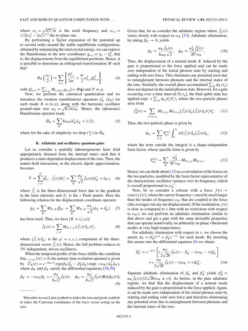
Coulomb—also named classical Wigner—crystals con-fined in Penning traps are natural candidates for a quantummemory, since the separation among ions, about 10 µm,allows one to individually manipulate their internal degreesof freedom. Such a trap scheme uses static electric fields toconfine charge particles in the axial direction (the z axis inFig. 1), whereas the radial confinement is provided by a stronguniform magnetic field along the axial direction. Currently,Penning traps allow one to trap up to 108 ions [25]. Anappropriate choice of the trap parameters (e.g., tight axialconfinement) allows the ionic ensemble to crystallize in atwo-dimensional (2D) hexagonal lattice configuration with aninterparticle spacing on the order of tens of µm [26] andtherefore to manipulate a large number of qubits withoutspecific microtrap designs. The high-phonon mode density,however, does not permit one to resolve single modes forsideband cooling. Hence, Doppler and sympathetic coolingare the most natural techniques to be employed; we also notethat Sisyphus cooling might be an alternative methodology[27]. Current experiments, however, performed with Dopplercooling, can reach temperatures of a few mK [28], that is, a highthermal occupation number distribution of phonon modes.Nonetheless, efficient quantum computation and productionof small cluster states are theoretically possible [29,30],and recently full control of the qubit Bloch vector with∼99.85% fidelity for Rabi flopping has been experimentallydemonstrated [31].
The two-qubit-gate scheme considered in the proposals ofRefs. [29,30] is based on the so-called “pushing gate” (or itsvariant, the modulated-carrier gate), where a spatially inhomo-geneous laser field together with an appropriate combinationof polarizations and frequencies induces a state-dependentdipole force on two nearest neighbors of the 2D Coulombcrystal (see Fig. 1). Depending on the configuration of lasersand polarizations the displacements of the ions away from
042319-11050-2947/2011/83(4)/042319(13) ©2011 American Physical Society
BALTRUSCH, NEGRETTI, TAYLOR, AND CALARCO PHYSICAL REVIEW A 83, 042319 (2011)
FIG. 1. (Color online) Two-dimensional Coulomb crystals of ionsin a Penning trap rotating at frequency ωr . To manipulate the internalstates of the ions, laser beams can address single sites or multipleions.
their equilibrium positions can be either perpendicular to theplane of the crystal [29] or along the in-plane separation of theions [30,32–34]. The coupling between these displacements,mediated by phonons, yields entanglement of the internalstates (qubits) of the ions, that is, the desired quantum gatebetween ions.
In addition to the confinement, the radial electric and axialmagnetic fields induce a drift that causes in-plane rotation ofthe crystal (see Fig. 1), whose frequency ωr/(2π ) is typicallyon the order of a few tens of kHz [26]. There are two possiblesolutions to our quantum hardware design: either we use acorotating (with the crystal) laser beam in order to realize thedesired two-qubit quantum gate or we have to perform the gatein a time, τg , such that the crystal rotation has a negligible effecton the gate operation. The latter solution translates into thecondition ωrτg/(2π ) � 1. Such a requirement is instrumentalbecause, in order to accumulate the necessary two-ion phasefor the quantum gate we aim to implement, the ions have toexperience the applied light force for the entire gate operationor else the required phase would be achieved only partially.
While the former solution applies for all rotation fre-quencies, but relies on a more sophisticated experimentalsetup, the latter restricts the range of possible values ofωr . Thus, in both proposals [29,30], where the rotation andcyclotron frequencies fulfill 2ωr = ωc, the aforementionedcondition is satisfied when τg is on the order of ns, whereasthe modulated-carrier gate of Ref. [30] had τg = 5 µs.Given the above, such a proposal requires a corotatinglaser beam. Thus, by maintaining 2ωr = ωc one shouldreduce ωc. This approach, however, would not help sincethe smaller the cyclotron frequency is, the longer the gateoperation. Instead, if we abandon the assumption 2ωr = ωc
and look at moderate rotation frequencies, at the expense ofpossible large modulations of the force, we are able to fulfillωrτg/(2π ) � 1. Additionally, low rotating frequencies resultin low densities and large interparticle spacing and thereforein an easier way to address the trapped ions with a laserfield.
Thus, the main goal of this work is to analyze this regimeand, at the same time, to perform robust two-qubit gates withina range of experimentally achievable temperatures.
In the following we present the general theory of themodulated-carrier-push two-qubit gate (Sec. II) with detailsthat were briefly mentioned in Ref. [30]. Subsequently, inSec. III, we investigate the situation in the presence of themagnetic field in the rotating frame of reference and the relativegate performance. In Sec. IV we describe how to physicallyrealize the state-dependent force required for the proposedquantum processor, and Sec. V summarizes our results andprovides some future prospectives.
II. MODULATED-CARRIER GATE
In the following we make the approximation that the Wignercrystal is a rigid body, which is a good approximation in themagnetohydrodynamic regime (one component plasma) or atequilibrium [35]. Hence, in a rotating frame, the Hamiltonianof a crystal with N ions written in cylindrical coordinates[�r ≡ (r,θ,z)] is given by [35]
HR(ω) =N∑
k=1
{p2
rk+ p2
zk
2m+[pθk
− m(ωc − 2ω)r2k
/2]2
2mr2k
}
+N∑
k=1
{ϒ(2z2
k − r2k
)+ m
2ω(ωc − ω)r2
k
}+ Vc,
(1)
with m being the mass of the ion and
Vc = e2
4πε0
∑k<j
1
|�rk − �rj | . (2)
Here ϒ is a parameter describing the trap geometry and appliedvoltage on the electrodes [36], ε0 is the vacuum permittivity,e is the electron charge, and ωc = eB/m is the cyclotronfrequency. We see, from the first line of Eq. (1), that there existsa special rotating frame, ω = ωc/2, such that the minimalcoupling disappears, and, in this section, we consider such aframe of reference together with ωr = ωc/2 (i.e., the frameof reference coincides with the crystal). We note that with“minimal coupling” we refer to the interaction �p · �A. Suchterminology is typically used in quantum-field theory [37].
Finally, it is worth reminding that the gate we aim toaccomplish realizes the true table |ε1,ε2〉 → eiθε1ε2 |ε1,ε2〉, withε1,2 = 0,1 and θ = θ00 − θ01 − θ10 + θ11 [33,34]. Specifically,we are interested in a phase gate with θ = π , which, up toadditional single-qubit rotations, is tantamount to a two-qubitcontrolled NOT gate [24].
A. Normal modes and canonical quantization
The Hamiltonian (1) in Cartesian coordinates [�r ≡ (x,y,z)]reduces to
HR
(ωc
2
)=
N∑k=1
{ �p 2k
2m+ m
2
[ω2
zz2k + ω2
xy
(x2
k + y2k
)]}+ Vc,
(3)
042319-2
FAST AND ROBUST QUANTUM COMPUTATION WITH . . . PHYSICAL REVIEW A 83, 042319 (2011)
where ωz = √4ϒ/m is the axial frequency and ωxy =
1/2(ω2c − 2ω2
z )1/2 the in-plane one.By performing a Taylor expansion of the potential up
to second order around the stable equilibrium configuration,obtained by minimizing the total crystal energy, we can expressthe Hamiltonian in the new coordinates qn,η ≡ ηn − η0
n, thatis, the displacements from the equilibrium positions. Hence, itis possible to determine an orthogonal transformation M suchthat1
HR
(ωc
2
)≈∑n,η
{P 2
n,η
2m+ m
2ω2
n,ηQ2n,η
}, (4)
with Qn,η = ∑k,µ Mn,η;k,µqk,µ[= Mq] and P ≡ p.
Now, we perform the canonical quantization and weintroduce the creation (annihilation) operators a
†K (aK ) for
each mode K ≡ (n,η), along with the harmonic oscillatorground-state size αK = √
h/mωK . Hence, the (phononic)Hamiltonian operator reads
HR =∑K
hωK (a†KaK + 1/2), (5)
where for the sake of simplicity we drop (ωc
2 ) in HR .
B. Adiabatic and oscillatory quantum gates
Let us consider a spatially inhomogeneous laser fieldappropriately detuned from the internal states such that itproduces a state-dependent displacement of the ions. Then, thematter-field interaction, in the electric dipole approximation,becomes
V =N∑
j=1
[ �qj · �fj (t)]σ zj =
∑K
αK√2fK (t)(a†
K + aK ), (6)
where �fj is the three-dimensional force due to the gradientin the laser intensity and σ z
j is the z Pauli matrix. Here thefollowing relation for the displacement coordinate operator
qK =∑K ′
MK ′;KQK ′ =∑K ′
MK ′;KαK√
2(aK + a
†K ) (7)
has been used. Thus, we have [K ≡ (j,µ)]
fK (t) =∑j ′,µ′
MK;j ′,µ′[ �fj ′ (t)]µ′ σ zj ′ , (8)
where [ �fj ′(t)]µ′ is the µ′ = x,y,z component of the three-dimensional vector �fj ′ (t). Hence, the full problem reduces to3N independent, driven oscillators.
When the temporal profile of the force fulfills the conditionlimt→±∞f (t) = 0, the unitary time evolution operator is givenby UK (t) = e−iφK (t) exp(βKa
†K − β∗
KaK ) exp(−iωKt a†KaK ),
where φK and βK satisfy the differential equations [38,39]
βK = −iωKβK + iαK
h√
2fK (t), φK = αK
h√
2fK (t)Re[βK (t)].
(9)
1Hereafter we use Latin symbols to index the ions and greek symbolsto index the Cartesian coordinates of the force vector acting on theions.
Given that, let us consider the adiabatic regime where fK (t)varies slowly with respect to ωK [33]. Adiabatic elimination,by taking βK → 0, yields
βK ≈ αKfK (t)
hωK
√2
, φK ≈ α2Kf 2
K (t)
2h2ωK
. (10)
Thus, the displacement of a normal mode K induced by thegate is proportional to the force applied and can be madezero independent of the initial phonon state by starting andending with zero force. This eliminates any potential error dueto entanglement between phonons and the internal states ofthe ions. Similarly, the overall phase accumulated
∑K φK (τg)
does not depend on the initial phonon state. However, for a gateoccurring over a time interval [0,τg], the final qubit state hasapplied exp(−i
∑nj φnj σ
zn σ z
j ), where the two-particle phasesarise from
f 2K (t) =
∑j,n;µ,η
MK;j,µMK;n,η[ �fj (t)]µ[ �fn(t)]ησzj σ z
n . (11)
Thus, the two-particle phase is given by
φnj =∑µ,η
S(nj )µη
∫ τg
0dt[ �fj (t)]µ[ �fn(t)]η, (12)
where the term outside the integral is a shape-independentform factor, whose specific form is given by
S(nj )µη =
∑K
α2K
2h2ωK
MK;j,µMK;n,η. (13)
Hence, we can think about (12) as a convolution of the forces onthe two particles, modified by the form factor representative ofthe characteristic oscillator variance over its frequency, whichis overall proportional to ω−1
K .Now, let us consider a scheme with a force f (t) →
cos(νt)f (t), where the carrier frequency ν must be much largerthan the modes of frequency ωK that are coupled to the force(this averages out any net displacement). If the modulation f (t)is slow as compared to ν (but with no restriction with respectto ωK ), we can perform an adiabatic elimination similar tothat above and get a gate with the same desirable propertiesthat can operate nontrivially on arbitrarily in-plane vibrationalmodes at very high temperatures.
For adiabatic elimination with respect to ν, we choose theansatz βK = β+
Keiνt + β−Ke−iνt for each mode. By inserting
this ansatz into the differential equation (9) we obtain
β+K = e−2iνt
[i
αK
2√
2hfK (t) − β−
K − i(ωK − ν)β−K
]
+ iαK
2√
2hfK (t) − i(ωK + ν)β+
K. (14)
Separate adiabatic elimination of β−K and β+
K yields β±K =
αKfK (t)/[2√
2h(ωK ± ν)]. As before, in the pure adiabaticregime, we find that the displacement of a normal modeinduced by the gate is proportional to the force applied. Again,it can be made zero independent of the initial phonon state bystarting and ending with zero force and therefore eliminatingany potential error due to entanglement between phonons andthe internal states of the ions.
042319-3
BALTRUSCH, NEGRETTI, TAYLOR, AND CALARCO PHYSICAL REVIEW A 83, 042319 (2011)
Now, we examine the two-particle phase induced in thisnew scenario. The time evolution of the phase is governedby [30]
φK = α2K
2h2
ωK(ω2
K − ν2) cos2(νt)f 2
K (t), (15)
where the quickly varying component cos2(νt) can be replacedwith 1/2. As described in the adiabatic regime, the overallphase-accumulated
∑K φK (τg), for a gate occurring over the
time interval [0,τg], does not depend on the phonon initialstate. In this case the pulse-shape-independent form factor isgiven by [30]
S(nj )µη = −
∑K
α2KωK
4h2(ν2 − ω2
K
)MK;j,µMK;n,η. (16)
Performing a Taylor expansion in 1/ν2 the first term isproportional to
∑K MK;j,µMK;n,η = δj,nδµ,η (δj,n indicates
the Kronecker symbol). This follows from the fact thatM is an orthogonal matrix. Physically, this arises due tothe coherent averaging of in-phase oscillating ions withoutany virtual excitation of phonons—accordingly, no two-bodyphase should be expected. The second term of the expansionis nonzero and yields
S(nj )µη = − 1
4hmν4
∑K
ω2KMK;j,µMK;n,η + O(ν−6). (17)
Compared to adiabatic push gates, the modulated-carrier gateis inverted in sign and it is multiplied (in phase) by a factor(ωK/ν)4/2 [see Eq. (13)]. In the case of a lateral operatingmodulated-carrier gate with ωxy � ν � ωz, the accumulatedphase is enhanced by a factor of (ωz/ν)4/2 with respect to anadiabatic push gate with a force moving the ions in the axial(z) direction for the same laser parameters. Given that, thegate time needed to perform a π -phase gate is reduced. In theopposite case, that is, for an adiabatic in-plane push gate (ωK ∼ωxy), and for the same laser parameters, the lateral modulated-carrier gate is reduced in phase, and therefore a longer τg isrequired. Thus, compared to the proposal of Ref. [29], wherethe push gate operates in the axial direction, our modulated-carrier gate working with in-plane modes yields a larger two-ion phase for a given set of laser parameters, and thereforeit enables one to perform a larger number of quantum gateswithin the coherence time of the system.
III. MODULATED-CARRIER GATE WITHMINIMAL COUPLING
In this section we analyze the situation where ωr �= ωc/2,for which we have three reasonable choices for the rotatingframe of reference:
(i) F1 coincides with the laboratory frame, where theequilibrium positions of the ions in the crystal are timedependent and the minimal coupling does not vanish;
(ii) F2 rotates with a frequency ω = ωc/2, as in theprevious section, where the minimal coupling vanishes, butthe equilibrium positions are time dependent;
(iii) F3 rotates with a frequency ω = ωr , where equilibriumpositions are time independent, but the minimal coupling doesnot vanish.
A. Equilibrium configuration of the crystal
Let us discuss which of the frames of reference F1,2,3
is more suitable to numerically determine the equilibriumconfiguration of the system for a fixed (a priori) value oftotal canonical angular momentum Pθ .2 Since we are notconcerned with relativistic velocities, the electromagneticfields involved in the problem are the same in all framesof reference. Consequently, the angular momentum of anion in a frame rotating with uniform angular velocity withrespect to the (inertial) laboratory frame coincides with theone in the latter [40]. This conclusion allows us to find theequilibrium configuration of the crystal, for a given value of Pθ ,by choosing a frame of reference rotating with angular velocityω = ωc/2 (the frame F2 in the above outlined list) in such away that the coordinate systems at the initial time t = 0 of F2
and F3 do coincide. Such a choice simplifies the numericalminimization procedure, because the minimal coupling in the(classical) Hamiltonian vanishes. We underscore, however,that F2 is utilized only at time t = 0 for the determinationof the equilibrium configuration of the crystal. Instead, fortimes t > 0 we use F3, where the equilibrium positions aretime independent. With such a choice the numerical effort inorder to assess the gate performance is significantly reduced.
Besides this, we also note that not all rotation frequencies ωr
of the crystal allow a stable configuration, that is, ions confinedwithin a well-defined spatial region. Indeed, by rewriting theaddend of the second sum in Eq. (1) as
ϒ(2z2
k − r2k
)+ m
2ωr (ωc − ωr )r2
k = mω2z
2
(z2k + βr2
k
)(18)
we see that the potential is confining if and only if β is positive.Here the anisotropy parameter β is defined as
β = ωr (ωc − ωr )
ω2z
− 1
2= ωr
α2zωc
(1 − ωr
ωc
)− 1
2, (19)
where αz = ωz/ωc. Importantly, β relies only on αz and theratio ωr/ωc. Thus the range of admissible frequencies is ωm <
ωr < ωc − ωm, where ωm = ωc/2 − ωxy is the magnetonfrequency [35]. Of course, the admissible regime is alsoconstrained by the condition αz < 1/
√2. In order to access
lower rotation frequencies, the trap parameters might bechanged by increasing ωxy , that is, by lowering ωz. Attentionhas to be paid, however, when ωc and ωz are changed, since dueto such a manipulation different structural phase transitionsmay occur. In particular, we are interested in the limit β � 1,where a 2D hexagonal lattice structure appears [35].
B. Quadratic expansion of the Hamiltonian
Let us introduce the typical scale of length �s , momentumps , and energy Es in our problem:
�s =(
e2
4πε0mω2c
) 13
, ps = �smωc, Es = e2
4πε0�s
. (20)
2When ωr �= ωc/2, the total canonical angular momentum Pθ �= 0,but it is still a constant of motion [35].
042319-4

FAST AND ROBUST QUANTUM COMPUTATION WITH . . . PHYSICAL REVIEW A 83, 042319 (2011)
Then, the Hamiltonian (1) in Cartesian coordinates becomes
HR(ω) = 1
2
N∑k=1
[p2
xk+ p2
yk+ p2
zk+ (
ykpxk− xkpyk
)
× (1 + 2α)]+ 1
4
N∑k=1
[α2
z
(2z2
k − r2k
)+ r2k
2
]
+ 1
2limε→0
N∑k,j=1
1 − δk,j
|�rk − �rj + ε| , (21)
where the substitutions HR(ω) → HR(ω)/Es , (r,z) →(r,z)/�s , (px,py,pz) → (px,py,pz)/ps , and α = ω/ωc havebeen introduced. The expression of the Coulomb potential,third line in Eq. (21), allows us to obtain more compactformulas later in the present section.
Next, given the equilibrium configuration (�r0,�0) of eachion, we expand the Hamiltonian (21) to second order in thespatial displacement q = r − r0 and p around zero, namely,
HR(p,q) HR(0,r0) + 12 dHRdT, (22)
where dT is the transpose of the row vector d ≡(q1,x,p1,x,q1,y ,p1,y , . . . ,qN,z,pN,z) and HR = HR(0,r0) is theHessian matrix. Its nonzero matrix elements are given by
∂2HR
∂p2ηk
= 1,∂2HR
∂pxk∂yk
= − ∂2HR
∂pyk∂xk
= α + 1
2,
∂2HR
∂ηk∂µj
= [1 − 2α2
z + (6α2
z − 1)δη,z
] δη,µδk,j
4
+ limε→0
N∑s=1
(1 − δk,s)[δs,j + (1 − δs,j )δ|k−j |,0]
|�rk − �rs + ε|3
× (−1)δk,j
[δη,µ − 3
(ηk − ηs)(µk − µs)
|�rk − �rs + ε|2]
,
where η,µ = x,y,z, and k,j = 1, . . . ,N .
C. Symplectic diagonalization and canonical quantization
Hereafter we utilize the frame F3 that rotates at thefrequency ωr . Hence, we are allowed to drop HR(0,r0) inEq. (22) and the full Hamiltonian reduces to the 6N × 6N
matrix HR(ωr ) = dHRdT/2.In order to perform the canonical quantization, we have first
to transform the classical Hamiltonian HR(ωr ) in canonicalform. A transformation S : (p,q) → (P,Q) is canonical whenthe condition SJST = J is satisfied, where J = i
⊕3Ni=1 σ y
[40]. Since the Hessian matrix HR is real and positive definite,Williamson’s theorem [41] guarantees that
SHRST = W =
⎛⎜⎜⎜⎝
ω1
ω1
. . .
ω3N
ω3N
⎞⎟⎟⎟⎠ , (23)
where ωk are real and positive numbers ∀k = 1, . . . ,3N andW is called the “Williamson form” of HR .
Given that, we can recast the classical Hamiltonian as
HR(ωr ) = 1
2
3N∑k=1
ωk�22k−1 + 1
2
3N∑k=1
ωk�22k, (24)
where the new coordinates are determined by the transfor-mation �T = (S−1)TdT. For the sake of simplicity, hereafter,we use the definitions Qk := �2k−1 and Pk := �2k ∀k =1, . . . ,3N . Thus, the Hamiltonian reduces to
HR(ωr ) = 1
2
3N∑k=1
ωk
(Q2
k + P 2k
), (25)
that is, a sum of uncoupled harmonic oscillators.Similarly to Sec. II A, we perform the canonical quanti-
zation by promoting Qk,Pk to operators such that [Qk,Ps] =iδk,s . Besides this, we introduce the operators ak = (Qk +iPk)/
√2, a
†k = (Qk − iPk)/
√2 with [ak,a
†s ] = δk,s . Hence,
the quantized Hamiltonian is simply given by
HR(ωr ) =3N∑k=1
ωk
(a†kak + 1
2
), (26)
and we note that the eigenvalues ωk are dimensionless.Finally, we rewrite the coupling between the ions and the
inhomogeneous laser field. The displacement of the ion fromits equilibrium position can be written as
dj = 1√2
3N∑k=1
A∗k,j ak + Ak,j a
†k (27)
with Akj = S2k−1,j + iS2k,j and where j is an odd integer[see the definition of the vector d after Eq. (22)]. Then, thematter-field interaction has the following expression
V =N∑
j=1
[�qj · �fj (t)]σ zj =
N−1∑j=0
σ zj+1
3∑n=1
F3j+n(t)d2(n+3j )−1
=3N∑k=1
α∗k ak + αka
†k, (28)
where F = (f1,x ,f1,y,f1,z, . . . ,fN,x,fN,y,fN,z) and
αk = 1√2
N−1∑j=0
σ zj+1
3∑n=1
F3j+n(t)Ak,2(n+3j )−1. (29)
Thus the full Hamiltonian is H = HR(ωr ) + V = ∑k Hk ,
where Hk = ωk(a†kak + 1
2 ) + α∗k ak + αka
†k .
D. Two-qubit phase gate
The time evolution of a phonon mode state, governed bythe Hamiltonian Hk , and a generic two-qubit state is
|�k; �qbit(t)〉 = e−iφk (t)D[βk(t)]e−iH 0k |�k; �qbit(0)〉, (30)
where D[βk(t)] is the displacement operator [42], βk(t) =−i
∫ t
0 dsαk(s)eiωk(s−t), and H 0k = ωk(a†
kak + 12 ).
In order to disentangle the external dynamics due to thephonons and the internal dynamics of the qubit states at the
042319-5
BALTRUSCH, NEGRETTI, TAYLOR, AND CALARCO PHYSICAL REVIEW A 83, 042319 (2011)
end of the gate operation, t = τg , the following condition hasto be satisfied [39]
Ik = 1√ωk
∫ τg
0dteiωktαk(t) = 0 ∀k. (31)
This condition, however, is more general than the adiabaticelimination we performed in Sec. II B, whose aim was tohighlight the difference in the accumulated two-particle phasesamong the most common quantum gate schemes based onpushing forces with off-resonant lasers.
The necessary lateral force on the j th and kth ion, | �fj | =| �fk| = APhωxy cos(νt)e−t2/τ 2
g /|�r 0j − �r 0
k |, is determined bysetting the dimensionless parameter AP to achieve a π phasebetween the chosen pair of qubits. Then the fidelity is givenby
F = min�′
qbit
{Trph[〈�′qbit|U(t)(ρT (0)
⊗ |�qbit〉〈�qbit|)U†(t)|�′
qbit〉]}
= min±
∏k
exp
[−A2
P
4
(∣∣I (j1)k ± I (j2)
k
∣∣21 − e−hωk/kBT
)], (32)
where U(t) is the unitary evolution operator defined throughEq. (30), ρT (0) is the initial (canonical) density operator of thephonon modes at temperature T , |�qbit〉 is the initial two-qubitstate, and
|�′qbit〉 =
1∑ε1,ε2=0
(−1)ε1ε2cε1,ε2 |ε1〉|ε2〉 (33)
is the desired logical target state we aim to attain. The integralI (jq )
k for q = 1,2 is given in Eq. (31) where the apex (jq) refersto the ion we are considering, that is, j = jq in the sum ofEq. (29).
Since we aim to achieve τg � 2π/ωr , we outline thefollowing program: First, we analyze the dependence ofωr on the total angular momentum Pθ . This is achievedby fixing a priori a value of Pθ and then by determiningthe equilibrium configuration of the crystal, namely, thepositions and momenta of each ion (the most difficult partof the program). Since the crystal is a rigid body, it holdspθk
= mr2k θk + erkAθ (rk) = mr2
k (ωr + ωc/2) [35], and fromthis relation the rotation frequency is extracted. Such ananalysis allows us to find the smallest value of ωr such thatβ < βc = 0.665/
√N is fulfilled, that is, a 2D Wigner crystal
configuration [35]. Then we choose the value of both ωc andν in order to achieve high gate fidelity for a wide range oftemperatures.
The determination of the classical ground state is a mul-tidimensional minimization constrained problem for whichno deterministic and efficient algorithm is known. Herewe used a variant of the Metropolis algorithm [43] andthe multidimensional constrained Newton algorithm like theone in Ref. [44]. The first method allows us to sample randomlythe relevant phase-space region by choosing a slow decay of theacceptance probability and by using several annealing cycles.We then coarse-grained the obtained annealing trajectoriesinto intervals, and we employed, for the lowest energyconfiguration on each interval, a Newton algorithm, which
−4000 −2000 0 2000 4000−0.6
−0.58
−0.56
−0.54
−0.52
−0.5
−0.48
−0.46
−0.44
−0.42
−0.4
P θ [units of 2smω c]
ωr/ω
c
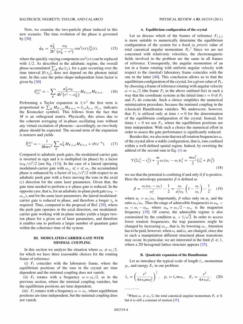
FIG. 2. Ratio ωr/ωc vs total angular momentum Pθ for αz = 0.7and N = 30. For Pθ = 0 we retrieve the well-known limit ωr = 2ωc,in which there is no magnetic field in the rotating frame.
is very efficient in finding a local minimum provided thatthe initial value is already very close. We have checked thereliability of our numerical energy minimization for Pθ = 0,that is, ωr = 2ωc, by comparing the results of Ref. [44] for theminimal excitation frequency for several numbers N of ions.
We investigated the robustness of the modulated-carrierphase gate against temperature for a moderate number of ionsN = 30 and αz = 0.70. In Fig. 2 the dependence of the crystalrotation frequency on the total canonical angular momentum isshown, whereas in Fig. 3 the gate infidelity for different valuesof the ratio τg/τr is displayed. The results of Fig. 3 refer toPθ = 4000�2
smωc, for which we obtain the smallest value of|ωr | in Fig. 2. Besides this, we have for such a choice β =3.4 × 10⁻⁴, whereas βc = 0.12, that is, a stable 2D hexagonallattice configuration. Given that, Fig. 3 shows that in orderto reduce by a factor 10 the ratio τg/τr the fast modulationfrequency ν of the force has to be (roughly) enhanced by afactor 10 as well. We also remark, that the three lines in Fig. 3show an infidelity that is smaller for large gate operation times.The goal of the plot is to show how the modulation frequencyincreases when the ratio τg/τr is reduced for an infidelitysmaller than 10−4. Of course, by carefully tuning ν one caneasily get a smaller infidelity for faster gates.
In the inset (top left corner) the result of the gate infidelityfor a cyclotron frequency 100 times higher is shown, that is, thesame 7.608 MHz of the experiment of Ref. [28]. Here there aretwo important features to be highlighted: first, the gate fidelityis more robust for a wide range of temperatures with respectto the previous case where ωc/(2π ) = 76.08 kHz has beenconsidered. On the other hand, already for τg/τr = 0.1, thefrequency ν is on the order of hundreds of MHz. In the inseton the right (bottom) we show the gate infidelity again for theωc = 7.608 MHz but for a smaller modulation frequency ν =2.4 MHz that lies in the gap between the two bands of differentradial modes (the so-called �E × �B and cyclotron modes, see
042319-6
FAST AND ROBUST QUANTUM COMPUTATION WITH . . . PHYSICAL REVIEW A 83, 042319 (2011)
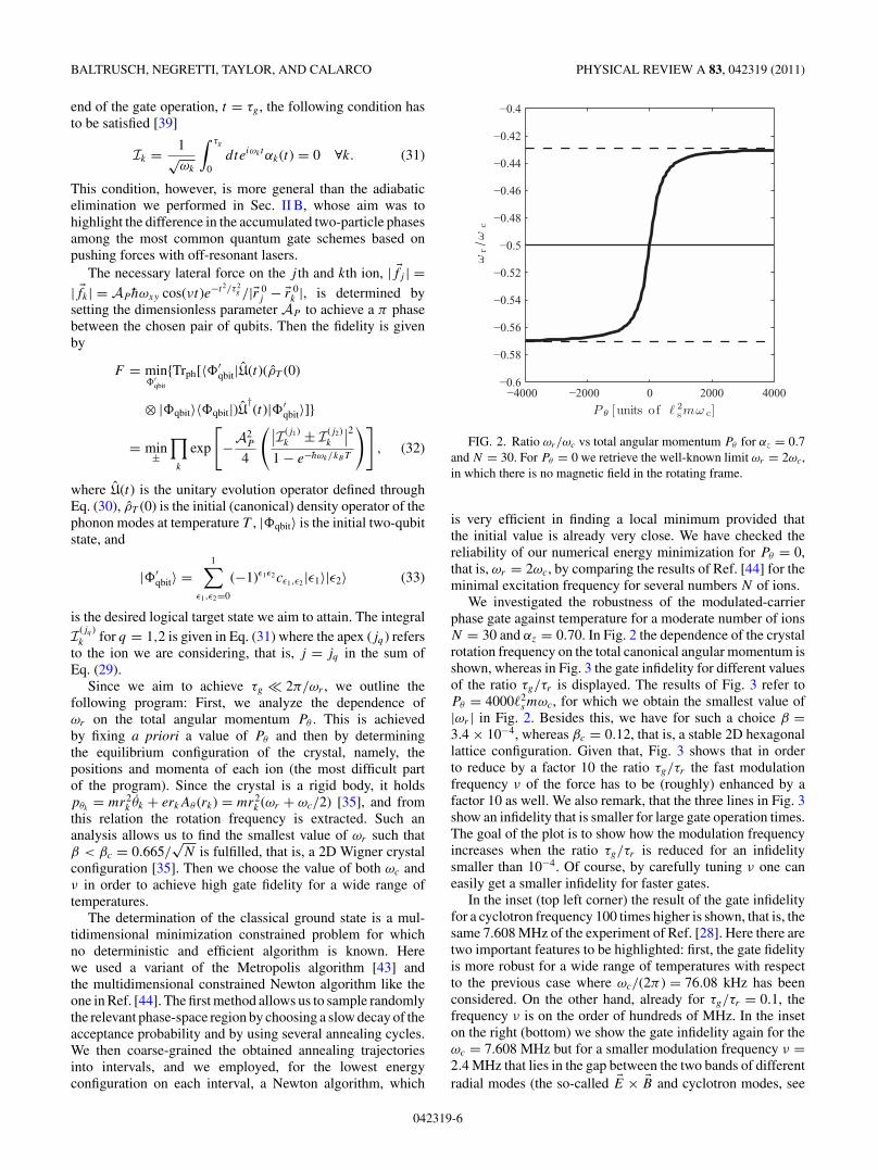
FIG. 3. (Color online) Infidelity vs temperature for αz = 0.7,N = 30, and Pθ = 4 × 10³�2
smωc. Parameters: νc = ωc/(2π ) =76.08 kHz, νxy = ωxy/(2π ) = 5.38 kHz, νz = ωz/(2π ) =53.26 kHz, and νr = ωr/(2π ) = 32.75 kHz. The black (solid)line corresponds to τg/τr = 10−1 (τg = 3 µs), the red (dashed)line to τg/τr = 10−2 (τg = 0.3 µs), and the blue (dashdot) line toτg/τr = 10−3 (τg = 0.03 µs), with τr = 2π/ωr . The inset (on thetop left corner) provides the infidelity for τg/τr = 10−1 (τg = 0.03µs), with νc = 7.61 MHz as in Ref. [28], ν = 300 MHz, νxy =537.97 kHz, νz = 5.33 MHz, and νr = 3.27 MHz. The inset (on thebottom right corner) illustrates, for the same trapping parametersas for the former inset but with ν = 2.4 MHz, the infidelity forτg/τr = 10 (τg = 3 µs). Such modulation frequency ν lies withinthe gap among radial and �E × �B phonon modes (see Fig. 5).
also Fig. 5). In this scenario τg/τr = 10 and therefore acorotating laser beam is required. In conclusion we see thatfor ωz ∼ ωc/
√2 if we desire to avoid the employment of a
corotating laser beam the only possible way is to achieve veryhigh frequencies for the modulation of the state-dependentforce.
Alternatively, one can consider a smaller value of αz, whichbasically shifts upward the graph of Fig. 2, that is, by displacingthe minimum of the |ωr | closer to zero for large values ofPθ . This is the situation depicted in Fig. 4 for N = 30, andαz = 0.02. Here it is possible to achieve gate operation timeson the order of few µs with significantly smaller values ofthe modulation frequency. In the figure ν lies in the gapamong axial and radial modes (see Fig. 5). Furthermore withτg/τr = 6 × 10⁻³ we do not need a corotating laser beam.This result is quite interesting since it works in a range ofparameters that are currently employed in experiments (e.g.,[31]). Finally we also note that in this scenario ωxy � ωz,which is opposite to the requirement we identified in the case
10−2
10−1
100
101
102
10−9
10−8
10−7
10−6
10−5
10−4
T [units of hνxy /kB ]
1−
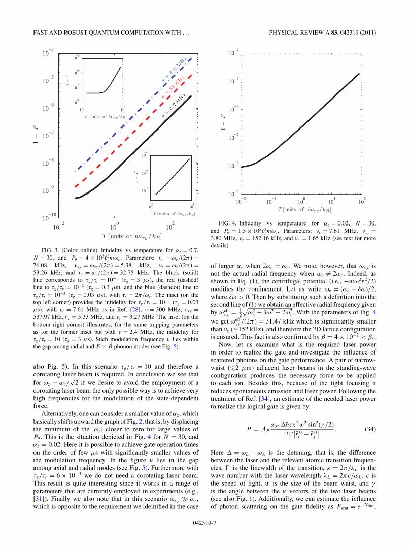
FFIG. 4. Infidelity vs temperature for αz = 0.02, N = 30,
and Pθ = 1.3 × 10⁵�2smωc. Parameters: νc = 7.61 MHz, νxy =
3.80 MHz, νz = 152.16 kHz, and νr = 1.65 kHz (see text for moredetails).
of larger αz when 2ωr = ωc. We note, however, that ωxy isnot the actual radial frequency when ωc �= 2ωr . Indeed, asshown in Eq. (1), the centrifugal potential (i.e., −mω2r2/2)modifies the confinement. Let us write ωr = (ωc − δω)/2,where δω > 0. Then by substituting such a definition into thesecond line of (1) we obtain an effective radial frequency givenby ωeff
xy = 12
√ω2
c − δω2 − 2ω2z . With the parameters of Fig. 4
we get ωeffxy /(2π ) = 31.47 kHz which is significantly smaller
than νz (∼152 kHz), and therefore the 2D lattice configurationis ensured. This fact is also confirmed by β = 4 × 10⁻² < βc.
Now, let us examine what is the required laser powerin order to realize the gate and investigate the influence ofscattered photons on the gate performance. A pair of narrow-waist (�2 µm) adjacent laser beams in the standing-waveconfiguration produces the necessary force to be appliedto each ion. Besides this, because of the tight focusing itreduces spontaneous emission and laser power. Following thetreatment of Ref. [34], an estimate of the needed laser powerto realize the logical gate is given by
P = AP
ωxy�hcκ2w2 sin2(γ /2)
3�∣∣�r 0
i − �r 0j
∣∣ . (34)
Here � = ωL − ωA is the detuning, that is, the differencebetween the laser and the relevant atomic transition frequen-cies, � is the linewidth of the transition, κ = 2π/λL is thewave number with the laser wavelength λL = 2πc/ωL, c isthe speed of light, w is the size of the beam waist, and γ
is the angle between the κ vectors of the two laser beams(see also Fig. 1). Additionally, we can estimate the influenceof photon scattering on the gate fidelity as Fscat = e−Nphot ,
042319-7
BALTRUSCH, NEGRETTI, TAYLOR, AND CALARCO PHYSICAL REVIEW A 83, 042319 (2011)
0 10 20 300
0.05
0.1
ω/ω
xy
0 10 20 301.95
2
2.05
2.1
0 10 20 309.88
9.89
9.9
0 10 20 300
1
2x 10
−4
ω/ω
xy
Mode index (E × B)0 10 20 30
0.03
0.04
0.05
Mode index (Radial)0 10 20 30
1.9999
2
2.0001
Mode index (Axial)
FIG. 5. Modes for the parameters consid-ered in Fig. 3 (top row, αz = 0.70, Pθ = 4 ×10³�2
smωc) and Fig. 4 (bottom row, αz = 0.02,Pθ = 1.3 × 10⁵�2
smωc).
where the number of scattered photons in the standing-waveconfiguration is given by
Nphot ≈√
2π3ε0c m2w2ω4xy
∣∣�r 0i − �r 0
j
∣∣33e2λLP
sin(γ
2
). (35)
As the last two formulas show, by adjusting γ we can reducethe required laser power, but at the expense of a larger numberof scattered photons and therefore of a worsening of the gateperformance.
IV. MODULATED AND STATE-DEPENDENT DIPOLEFORCE
In order to realize our quantum phase gate, |ε1,ε2〉 →eiθε1ε2 |ε1,ε2〉 with ε1,2 = 0,1, we have to engineer the θkj
phases in θ (see also Sec. II). It is natural to demand thatthe desired value of θ is obtained with the smallest possible
FIG. 6. Energy shifts due to the Zeeman effect vs the mj quantumnumber. The distances among the energy levels are not in scale.
value of the applied force (i.e., laser power) or, alternatively,in the shortest possible time. This is equivalent to maximize θ
by maximizing the effect of each θkj . This happens when thephases θ01 and θ10 have the opposite sign with respect to thephases θ00 and θ11. Such a condition is met when the appliedforce to the j th ion satisfies the relation
�f |0〉j = − �f |1〉
j . (36)
Additionally, a necessary condition for the implementation ofa modulated-carrier quantum phase gate is that the mean forceacting on each ion (respectively, each of the modes) has tobe zero over τg; that is, we have to fulfill Eq. (31). Such arequirement can be accomplished by making the modulationtime symmetric around the center of the envelope of the laserpulse. To this aim, we impose the further condition on theforce: ∫ τ
0dt �f |k〉
j (t) = 0 ∀k = 0,1, (37)
where τ = 2π/ν is one period of the modulation. With sucha condition we obtain a (fast) sinusoidal modulation of theforce. Experimentally, this can be achieved, for example, withan acousto-optical modulator, which can vary the frequency ofthe laser light very quickly.
A. Energy shifts
In Table I we provide for some ion species the energysplitting between the P1/2 and P3/2 levels in the absence ofan external magnetic field together with the maximal value ofmagnetic field BZ , under which the (normal) Zeeman limitcan be applied, and the minimal value BPB, above whichwe enter in the Paschen-Back regime. As we can gatherfrom the table, the higher the atomic number of the ion(or neutral atom) is, the larger �E and the limits BZ andBPB. For instance, for the infidelity results we showed inthe previous section, the corresponding magnetic fields atωc = 7.608 MHz are B = 4.5 T and B = 12 T for berylliumand magnesium, respectively. These are also the values used incurrent experiments. Thus, for all alkaline-earth-metal atomsthe Zeeman regime applies, and therefore HB = µB
hgJ JzBz
well describes the interaction of an ion with the externalmagnetic field. Here gJ is the Lande factor [45] and the nuclear
042319-8
FAST AND ROBUST QUANTUM COMPUTATION WITH . . . PHYSICAL REVIEW A 83, 042319 (2011)
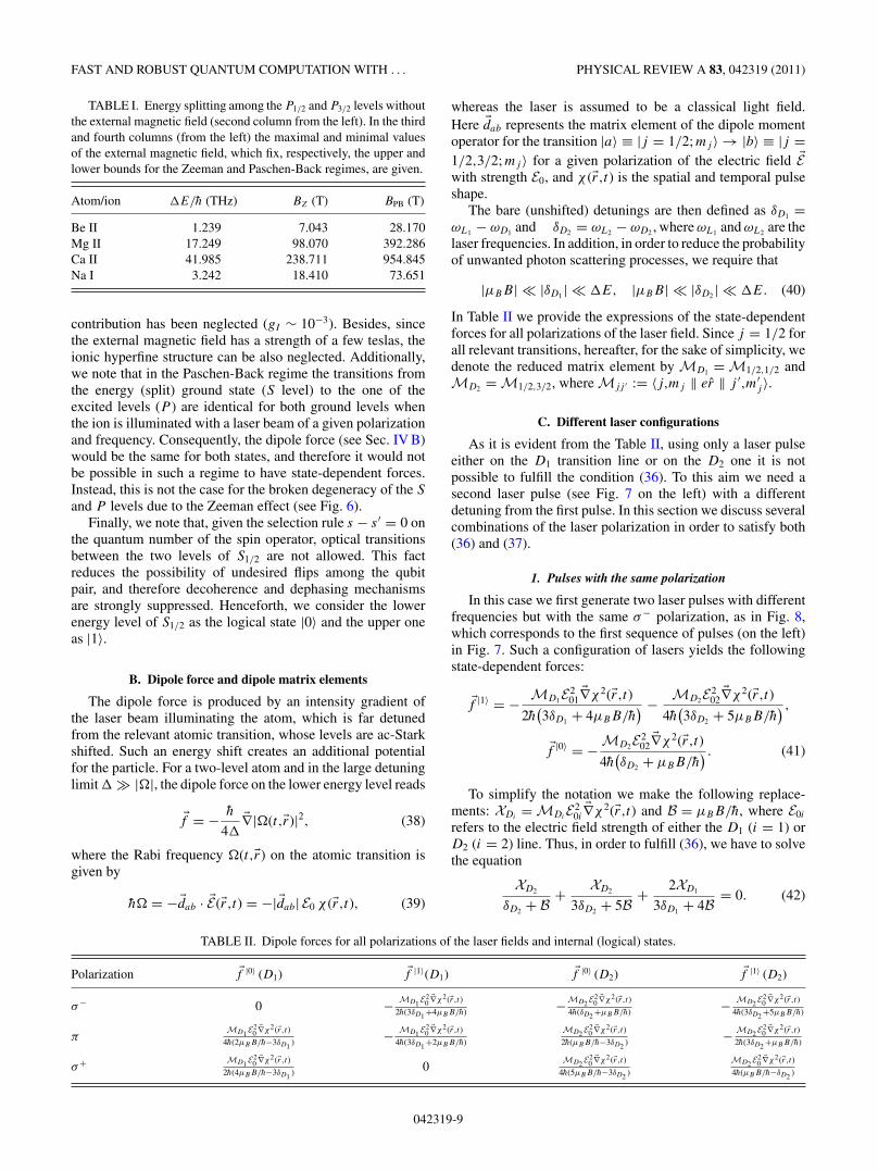
TABLE I. Energy splitting among the P1/2 and P3/2 levels withoutthe external magnetic field (second column from the left). In the thirdand fourth columns (from the left) the maximal and minimal valuesof the external magnetic field, which fix, respectively, the upper andlower bounds for the Zeeman and Paschen-Back regimes, are given.
Atom/ion �E/h (THz) BZ (T) BPB (T)
Be II 1.239 7.043 28.170Mg II 17.249 98.070 392.286Ca II 41.985 238.711 954.845Na I 3.242 18.410 73.651
contribution has been neglected (gI ∼ 10−3). Besides, sincethe external magnetic field has a strength of a few teslas, theionic hyperfine structure can be also neglected. Additionally,we note that in the Paschen-Back regime the transitions fromthe energy (split) ground state (S level) to the one of theexcited levels (P ) are identical for both ground levels whenthe ion is illuminated with a laser beam of a given polarizationand frequency. Consequently, the dipole force (see Sec. IV B)would be the same for both states, and therefore it would notbe possible in such a regime to have state-dependent forces.Instead, this is not the case for the broken degeneracy of the S
and P levels due to the Zeeman effect (see Fig. 6).Finally, we note that, given the selection rule s − s ′ = 0 on
the quantum number of the spin operator, optical transitionsbetween the two levels of S1/2 are not allowed. This factreduces the possibility of undesired flips among the qubitpair, and therefore decoherence and dephasing mechanismsare strongly suppressed. Henceforth, we consider the lowerenergy level of S1/2 as the logical state |0〉 and the upper oneas |1〉.
B. Dipole force and dipole matrix elements
The dipole force is produced by an intensity gradient ofthe laser beam illuminating the atom, which is far detunedfrom the relevant atomic transition, whose levels are ac-Starkshifted. Such an energy shift creates an additional potentialfor the particle. For a two-level atom and in the large detuninglimit � � |�|, the dipole force on the lower energy level reads
�f = − h
4��∇|�(t,�r)|2, (38)
where the Rabi frequency �(t,�r) on the atomic transition isgiven by
h� = −�dab · �E(�r,t) = −| �dab| E0 χ (�r,t), (39)
whereas the laser is assumed to be a classical light field.Here �dab represents the matrix element of the dipole momentoperator for the transition |a〉 ≡ |j = 1/2; mj 〉 → |b〉 ≡ |j =1/2,3/2; mj 〉 for a given polarization of the electric field �Ewith strength E0, and χ (�r,t) is the spatial and temporal pulseshape.
The bare (unshifted) detunings are then defined as δD1 =ωL1 − ωD1 and δD2 = ωL2 − ωD2 , where ωL1 and ωL2 are thelaser frequencies. In addition, in order to reduce the probabilityof unwanted photon scattering processes, we require that
|µBB| � |δD1 | � �E, |µBB| � |δD2 | � �E. (40)
In Table II we provide the expressions of the state-dependentforces for all polarizations of the laser field. Since j = 1/2 forall relevant transitions, hereafter, for the sake of simplicity, wedenote the reduced matrix element by MD1 = M1/2,1/2 andMD2 = M1/2,3/2, where Mjj ′ := 〈j,mj ‖ er ‖ j ′,m′
j 〉.
C. Different laser configurations
As it is evident from the Table II, using only a laser pulseeither on the D1 transition line or on the D2 one it is notpossible to fulfill the condition (36). To this aim we need asecond laser pulse (see Fig. 7 on the left) with a differentdetuning from the first pulse. In this section we discuss severalcombinations of the laser polarization in order to satisfy both(36) and (37).
1. Pulses with the same polarization
In this case we first generate two laser pulses with differentfrequencies but with the same σ− polarization, as in Fig. 8,which corresponds to the first sequence of pulses (on the left)in Fig. 7. Such a configuration of lasers yields the followingstate-dependent forces:
�f |1〉 = − MD1E201
�∇χ2(�r,t)2h(3δD1 + 4µBB/h
) − MD2E202
�∇χ2(�r,t)4h(3δD2 + 5µBB/h
) ,�f |0〉 = − MD2E2
02�∇χ2(�r,t)
4h(δD2 + µBB/h
) . (41)
To simplify the notation we make the following replace-ments: XDi
= MDiE2
0i�∇χ2(�r,t) and B = µBB/h, where E0i
refers to the electric field strength of either the D1 (i = 1) orD2 (i = 2) line. Thus, in order to fulfill (36), we have to solvethe equation
XD2
δD2 + B + XD2
3δD2 + 5B + 2XD1
3δD1 + 4B = 0. (42)
TABLE II. Dipole forces for all polarizations of the laser fields and internal (logical) states.
Polarization �f |0〉 (D1) �f |1〉(D1) �f |0〉 (D2) �f |1〉 (D2)
σ− 0 − MD1 E20
�∇χ2(�r,t)2h(3δD1 +4µBB/h) −MD2 E
20
�∇χ2(�r,t)4h(δD2 +µBB/h) − MD2 E
20
�∇χ2(�r,t)4h(3δD2 +5µBB/h)
πMD1 E
20
�∇χ2(�r,t)4h(2µBB/h−3δD1 ) − MD1 E
20
�∇χ2(�r,t)4h(3δD1 +2µBB/h)
MD2 E20
�∇χ2(�r,t)2h(µBB/h−3δD2 ) − MD2 E
20
�∇χ2(�r,t)2h(3δD2 +µBB/h)
σ+ MD1 E20
�∇χ2(�r,t)2h(4µBB/h−3δD1 ) 0
MD2 E20
�∇χ2(�r,t)4h(5µBB/h−3δD2 )
MD2 E20
�∇χ2(�r,t)4h(µBB/h−δD2 )
042319-9

BALTRUSCH, NEGRETTI, TAYLOR, AND CALARCO PHYSICAL REVIEW A 83, 042319 (2011)
FIG. 7. (Color online) Sketch of the pulse sequence in order todesign the necessary dipole forces to implement the modulated-carrierphase gate. The upper lines are red detuned, whereas the lower linesare blue detuned. In the figures the time is in arbitrary units.
This can be resolved for both the intensities or the detunings,so one of them can be considered as a given parameter. For theσ+ polarization we obtain an analog equation:
XD2
δD2 − B + XD2
3δD2 − 5B + 2XD1
3δD1 − 4B = 0. (43)
As an example, we solve equation Eq. (43), for instance, forthe intensities, and we obtain
XD1
XD2
=(4B − 3δD1 )(2δD2 − 3B
)(δD2 − B
)(3δD2 − 5B
) . (44)
Such a solution, however, fulfills only the condition (36)but not the one given by Eq. (37). To this aim we need anadditional two-pulse sequence, as shown in Fig. 7 on the right.Such two pulses can have different strengths of intensities anddetunings, but they must have the same spatial and temporalprofile χ (�r,t) of the first sequence. Again, we get, if we solvewith respect to the intensities, a solution like the one givenin Eq. (44), which in general will be different from the solution(44) for the first sequence of pulses. With such a solution wecan then easily satisfy also the mean zero force condition(37) by adjusting the ratios of either the intensities or thedetunings.
In Fig. 9 we display a simple example that shows how toachieve the necessary laser pulse sequence. We modulate theintensities of the blue (b) and red (r) detuned laser signals likeI b(r)(t) = I
b(r)0 sin2(νt). The sequence starts (t = 0) with both
FIG. 8. (Color online) Modulated-carrier gate with the samepolarization of the laser fields: σ− polarized (left) and σ+ po-larized (right). The distances among the energy levels are notin scale.
0 1 2 3 40
0.2
0.4
0.6
0.8
1
f[a
rb.
0 1 2 3 40
0.2
0.4
0.6
0.8
1
0 1 2 3 40
0.2
0.4
0.6
0.8
1
t [ units o f π/ν ]0 1 2 3 4
−1
−0.5
0
0.5
1
t [ units o f π/ν ]
unit
s]f
[arb.u
nits
]
FIG. 9. (Color online) Designed laser modulation forces in orderto fulfill both (37) and (36). The blue detuned laser intensity witha superimposed square wave signal (top left) and similarly for thered detuned one (top right). The resulting signals are depicted on thebottom left, whereas switching of polarization is given on the bottomright.
lasers with σ+ polarization and an intensity ratio R+ = I b0 /I r
0given by Eq. (44). Then, at time t = π/ν, the polarization ofthe two laser fields is changed to σ− with another intensityratio given by R− = I b
0 /I r0 . The ratio R− will differ from
R+, since in general the dipole moments are different forthe two polarizations. Thus, by changing the polarization ateach minimum of the laser intensity and by choosing theproper ratio R± we are able to fulfill the condition (37).In order to satisfy the condition (36) we have to designfurthermore the ratio of the two successive pulses. This is doneby multiplying the two intensities I b(r)(t) with square wavesignals which are displayed in Fig. 9 (top) by the black lines.The resulting pulses are shown in Fig. 9 (bottom left) and theirpolarization state is depicted in the right lower corner. Thisprocedure ensures that both the conditions (37) and (36) arefulfilled.
2. Pulses with the different polarization
The situation in which the laser beams have differentpolarizations is depicted in Fig. 10. If we illuminate the ionwith red detuned and σ+ polarized light and with a blueddetuned and σ− beam (Fig. 10 on the left), we have thefollowing state-dependent forces:
�f |1〉 = − MD2E20�∇χ2(�r,t)
4h(3δD2 + 5µBB/h
) ,�f |0〉 = MD1E2
0�∇χ2(�r,t)
2h(4µBB/h − 3δD1
) − MD2E20�∇χ2(�r,t)
4h(δD2 + µBB/h
) , (45)
042319-10
FAST AND ROBUST QUANTUM COMPUTATION WITH . . . PHYSICAL REVIEW A 83, 042319 (2011)
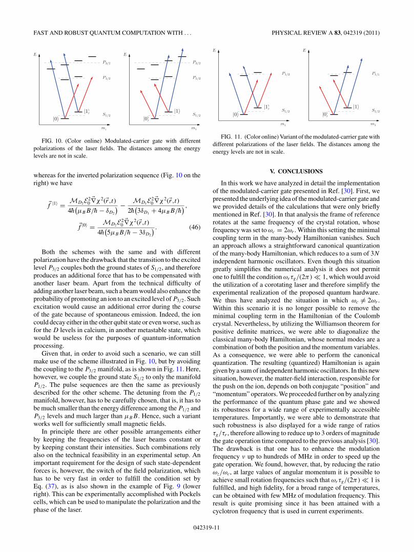
FIG. 10. (Color online) Modulated-carrier gate with differentpolarizations of the laser fields. The distances among the energylevels are not in scale.
whereas for the inverted polarization sequence (Fig. 10 on theright) we have
�f |1〉 = MD2E20�∇χ2(�r,t)
4h(µBB/h − δD2
) − MD1E20�∇χ2(�r,t)
2h(3δD1 + 4µBB/h
) ,�f |0〉 = MD2E2
0�∇χ2(�r,t)
4h(5µBB/h − 3δD2
) . (46)
Both the schemes with the same and with differentpolarization have the drawback that the transition to the excitedlevel P3/2 couples both the ground states of S1/2, and thereforeproduces an additional force that has to be compensated withanother laser beam. Apart from the technical difficulty ofadding another laser beam, such a beam would also enhance theprobability of promoting an ion to an excited level of P3/2. Suchexcitation would cause an additional error during the courseof the gate because of spontaneous emission. Indeed, the ioncould decay either in the other qubit state or even worse, such asfor the D levels in calcium, in another metastable state, whichwould be useless for the purposes of quantum-informationprocessing.
Given that, in order to avoid such a scenario, we can stillmake use of the scheme illustrated in Fig. 10, but by avoidingthe coupling to the P3/2 manifold, as is shown in Fig. 11. Here,however, we couple the ground state S1/2 to only the manifoldP1/2. The pulse sequences are then the same as previouslydescribed for the other scheme. The detuning from the P1/2
manifold, however, has to be carefully chosen, that is, it has tobe much smaller than the energy difference among the P1/2 andP3/2 levels and much larger than µBB. Hence, such a variantworks well for sufficiently small magnetic fields.
In principle there are other possible arrangements eitherby keeping the frequencies of the laser beams constant orby keeping constant their intensities. Such combinations relyalso on the technical feasibility in an experimental setup. Animportant requirement for the design of such state-dependentforces is, however, the switch of the field polarization, whichhas to be very fast in order to fulfill the condition set byEq. (37), as is also shown in the example of Fig. 9 (lowerright). This can be experimentally accomplished with Pockelscells, which can be used to manipulate the polarization and thephase of the laser.
FIG. 11. (Color online) Variant of the modulated-carrier gate withdifferent polarizations of the laser fields. The distances among theenergy levels are not in scale.
V. CONCLUSIONS
In this work we have analyzed in detail the implementationof the modulated-carrier gate presented in Ref. [30]. First, wepresented the underlying idea of the modulated-carrier gate andwe provided details of the calculations that were only brieflymentioned in Ref. [30]. In that analysis the frame of referencerotates at the same frequency of the crystal rotation, whosefrequency was set to ωc = 2ωr . Within this setting the minimalcoupling term in the many-body Hamiltonian vanishes. Suchan approach allows a straightforward canonical quantizationof the many-body Hamiltonian, which reduces to a sum of 3N
independent harmonic oscillators. Even though this situationgreatly simplifies the numerical analysis it does not permitone to fulfill the condition ωrτg/(2π ) � 1, which would avoidthe utilization of a corotating laser and therefore simplify theexperimental realization of the proposed quantum hardware.We thus have analyzed the situation in which ωc �= 2ωr .Within this scenario it is no longer possible to remove theminimal coupling term in the Hamiltonian of the Coulombcrystal. Nevertheless, by utilizing the Williamson theorem forpositive definite matrices, we were able to diagonalize theclassical many-body Hamiltonian, whose normal modes are acombination of both the position and the momentum variables.As a consequence, we were able to perform the canonicalquantization. The resulting (quantized) Hamiltonian is againgiven by a sum of independent harmonic oscillators. In this newsituation, however, the matter-field interaction, responsible forthe push on the ion, depends on both conjugate “position” and“momentum” operators. We proceeded further on by analyzingthe performance of the quantum phase gate and we showedits robustness for a wide range of experimentally accessibletemperatures. Importantly, we were able to demonstrate thatsuch robustness is also displayed for a wide range of ratiosτg/τr , therefore allowing to reduce up to 3 orders of magnitudethe gate operation time compared to the previous analysis [30].The drawback is that one has to enhance the modulationfrequency ν up to hundreds of MHz in order to speed up thegate operation. We found, however, that, by reducing the ratioωz/ωc, at large values of angular momentum it is possible toachieve small rotation frequencies such that ωrτg/(2π ) � 1 isfulfilled, and high fidelity, for a broad range of temperatures,can be obtained with few MHz of modulation frequency. Thisresult is quite promising since it has been attained with acyclotron frequency that is used in current experiments.
042319-11
BALTRUSCH, NEGRETTI, TAYLOR, AND CALARCO PHYSICAL REVIEW A 83, 042319 (2011)
Finally, we have provided a complete description for thedesign of the necessary forces to be applied on the ions inorder to accomplish the desired quantum computation scheme.To this aim, we have analyzed the experimentally relevantregion of external magnetic field. For all alkaline-earth-metalion species normally used in current experiments the normalZeeman effect provides, with good approximation, the rightdescription of the energy shifts of the S and P levels.In addition, we have also analyzed several possible laserconfigurations and for each one we discussed advantages aswell as drawbacks and, in some cases, we suggested alternativesolutions.
Further investigations of such a quantum computing pro-posal may rely on further optimization of both the forcemodulation together with a reduced gate operation time and itsrobustness against optimal pulse distortions [46]. This can beachieved by means of quantum optimal control techniques.Besides this, a detailed analysis, similar to Ref. [9], inorder to characterize and quantify all types of errors comingfrom the quantum dynamics, especially due to nonlinearities
in the ion-pushing force, will be pursued in futureinvestigations.
ACKNOWLEDGMENTS
We are grateful to J. J. Bollinger for his critical reading ofthe manuscript. J.B. acknowledges G. De Chiara and E. Kajarifor helpful discussions and A.N. useful correspondence withE. Pagani on symplectic transformations. We acknowledgefinancial support from the EU Integrated Project AQUTE,PICC (T.C.), the Deutsche Forschungsgemeinschaft withinGrant No. SFB/TRR21 (A.N., T.C.), the Marie Curie pro-gram of the European Commission (Proposal No. 236073,OPTIQUOS) within the 7th European Community FrameworkProgramme (A.N.), the Forschungsbonus of the Universityof Ulm and of the Ulmer Universitatsgesellschaft (A.N.),the Spanish Ministry of Science and Innovation (ConsoliderIngenio 2010 “QOIT,” QNLP FIS2007-66944), and the Eu-ropean Science Foundation (EUROQUAM “Cavity-MediatedMolecular Cooling”) (J.B.).
[1] E. Charron, E. Tiesinga, F. Mies, and C. Williams, Phys. Rev.Lett. 88, 077901 (2002).
[2] J. P. Palao and R. Kosloff, Phys. Rev. Lett. 89, 188301 (2002).[3] T. Calarco, U. Dorner, P. S. Julienne, C. J. Williams, and
P. Zoller, Phys. Rev. A 70, 012306 (2004).[4] P. Treutlein, T. W. Hansch, J. Reichel, A. Negretti, M. A. Cirone,
and T. Calarco, Phys. Rev. A 74, 022312 (2006).[5] E. Charron, M. A. Cirone, A. Negretti, J. Schmiedmayer, and
T. Calarco, Phys. Rev. A 74, 012308 (2006).[6] S. Montangero, T. Calarco, and R. Fazio, Phys. Rev. Lett. 99,
170501 (2007).[7] F. Motzoi, J. M. Gambetta, P. Rebentrost, and F. K. Wilhelm,
Phys. Rev. Lett. 103, 110501 (2009).[8] S. Safaei, S. Montangero, F. Taddei, and R. Fazio, Phys. Rev. B
79, 064524 (2009).[9] U. V. Poulsen, S. Sklarz, D. Tannor, and T. Calarco, Phys. Rev.
A 82, 012339 (2010).[10] A. M. Steane, Phys. Rev. A 68, 042322 (2003).[11] E. Knill, Phys. Rev. A 71, 042322 (2005).[12] D. Leibfried et al., Nature (London) 422, 412 (2003).[13] J. Benhelm, G. Kirchmair, C. F. Roos, and R. Blatt, Nat. Phys.
4, 463 (2008).[14] S. Gulde, M. Riebe, G. P. T. Lancaster, C. Becher, J. Eschner,
H. Haffner, F. Schmidt-Kaler, I. L. Chuang, and R. Blatt, Nature(London) 421, 48 (2003).
[15] J. Chiaverini et al., Science 308, 997 (2005).[16] D. Kielpinski, C. Monroe, and D. J. Wineland, Nature (London)
417, 709 (2002).[17] D. Stick, W. K. Hensinger, S. Olmschenk, M. J. Madsen,
K. Schwab, and C. Monroe, Nat. Phys. 2, 36 (2006).[18] R. Folman, P. Kruger, D. Cassettari, B. Hessmo, T. Maier, and
J. Schmiedmayer, Phys. Rev. Lett. 84, 4749 (2000).[19] J. Reichel, W. Hansel, and T. W. Hansch, Phys. Rev. Lett. 83,
3398 (1999).
[20] M. Oskin, F. T. Chong, and I. L. Chuang, IEEE Computer 35,79 (2002).
[21] J. I. Cirac, P. Zoller, H. J. Kimble, and H. Mabuchi, Phys. Rev.Lett. 78, 3221 (1997).
[22] E. Brion, K. Mølmer, and M. Saffman, Phys. Rev. Lett. 99,260501 (2007).
[23] A. Steane, C. F. Roos, D. Stevens, A. Mundt, D. Leibfried,F. Schmidt-Kaler, and R. Blatt, Phys. Rev. A 62, 042305 (2000).
[24] G. Chen, D. A. Church, B.-G. Englert, C. Henkel, B. Rohwedder,M. O. Scully, and M. S. Zubairy, Quantum Computing Devices:Principles, Designs, and Analysis (Chapman & Hall/CRC Taylor& Francis Group, Boca Raton, FL, 2006).
[25] F. Anderegg, C. F. Driscoll, C. H. E. Dubin, and T. M. O’Neil,Phys. Plasmas 17, 055702 (2010).
[26] T. B. Mitchell, J. J. Bollinger, D. H. E. Dubin, X.-P. Huang,W. M. Itano, and R. H. Baughman, Science 282, 1290 (1998).
[27] D. J. Wineland, J. Dalibard, and C. Cohen-Tannoudji, J. Opt.Soc. Am. B 9, 32 (1992).
[28] T. B. Mitchell, J. J. Bollinger, W. M. Itano, and D. H. E. Dubin,Phys. Rev. Lett. 87, 183001 (2001).
[29] D. Porras and J. I. Cirac, Phys. Rev. Lett. 96, 250501(2006).
[30] J. M. Taylor and T. Calarco, Phys. Rev. A 78, 062331 (2008).[31] M. J. Biercuk, H. Uys, A. P. VanDevender, N. Shiga, W. M.
Itano, and J. J. Bollinger, Quantum Inf. Comput. 9, 920 (2009).[32] J. I. Cirac and P. Zoller, Nature (London) 404, 579 (2000).[33] T. Calarco, J. I. Cirac, and P. Zoller, Phys. Rev. A 63, 062304
(2001).[34] M. Sasura and A. M. Steane, Phys. Rev. A 67, 062318
(2003).[35] D. H. E. Dubin and T. M. O’Neil, Rev. Mod. Phys. 71, 87 (1999).[36] P. K. Gosh, Ion Traps (Claredon Press, Oxford, 1995).[37] C. Itzykson and J. B. Zuber, Quantum Field Theory (McGraw–
Hill, New York, 1980).
042319-12

FAST AND ROBUST QUANTUM COMPUTATION WITH . . . PHYSICAL REVIEW A 83, 042319 (2011)
[38] J. J. Garcıa-Ripoll, P. Zoller, and J. I. Cirac, Phys. Rev. Lett. 91,157901 (2003).
[39] J. J. Garcıa-Ripoll, P. Zoller, and J. I. Cirac, Phys. Rev. A 71,062309 (2005).
[40] A. Fasano and S. Marmi, Analytical Mechanics (Oxford Univer-sity Press, New York, 2006).
[41] J. Williamson, Am. J. Math. 58, 141 (1936).[42] C. W. Gardiner and P. Zoller, Quantum Noise, Springer Series
in Synergetics (Springer, Heidelberg, 2004).
[43] N. Metropolis, A. W. Rosenbluth, M. N. Rosenbluth,A. H. Teller, and E. Teller, J. Chem. Phys. 21, 1087(1953).
[44] V. A. Schweigert and F. M. Peeters, Phys. Rev. B 51, 7700(1995).
[45] H. A. Bethe and E. E. Salpeter, Quantum Mechanics of One-and Two-Electron Atoms (Oxford University Press, New York,1957).
[46] A. Negretti, R. Fazio, and T. Calarco, e-print arXiv:1007.2405.
042319-13


![Title Fault-Tolerant Quantum Computation on Logical Cluster ......quantum computation under imperfect gate operations, namely fault-tolerant quantum computation [11, 12]. The main](https://img.pdfslide.net/doc/110x75/60f3fd58ff2b1f2547000d7a/title-fault-tolerant-quantum-computation-on-logical-cluster-quantum-computation.jpg)