Embed Size (px)
Citation preview
1
1
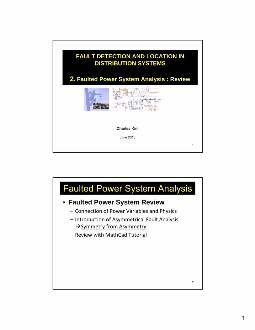
FAULT DETECTION AND LOCATION IN DISTRIBUTION SYSTEMS
2. Faulted Power System Analysis : Review
Charles Kim
June 2010
2
Faulted Power System Analysis• Faulted Power System Review
– Connection of Power Variables and Physics
– Introduction of Asymmetrical Fault Analysis Symmetry from Asymmetry
– Review with MathCad Tutorial
2
3
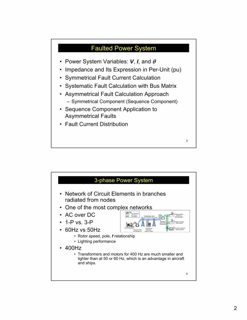
Faulted Power System
• Power System Variables: V, I, and θ• Impedance and Its Expression in Per-Unit (pu)• Symmetrical Fault Current Calculation• Systematic Fault Calculation with Bus Matrix• Asymmetrical Fault Calculation Approach
– Symmetrical Component (Sequence Component)• Sequence Component Application to
Asymmetrical Faults• Fault Current Distribution
4
3-phase Power System
• Network of Circuit Elements in branches radiated from nodes
• One of the most complex networks• AC over DC• 1-P vs. 3-P• 60Hz vs 50Hz
• Rotor speed, pole, f relationship• Lighting performance
• 400Hz• Transformers and motors for 400 Hz are much smaller and
lighter than at 50 or 60 Hz, which is an advantage in aircraft and ships.
3
5
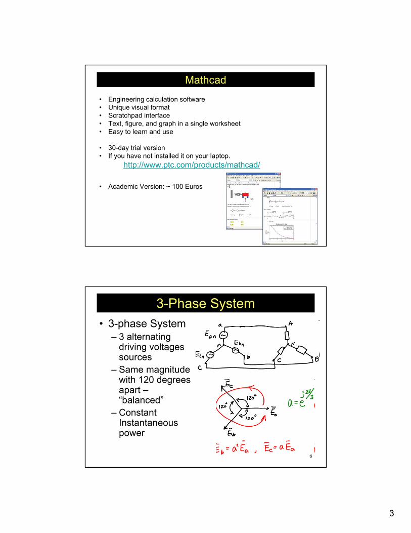
Mathcad
• Engineering calculation software• Unique visual format• Scratchpad interface• Text, figure, and graph in a single worksheet• Easy to learn and use
• 30-day trial version• If you have not installed it on your laptop.
http://www.ptc.com/products/mathcad/
• Academic Version: ~ 100 Euros
6
3-Phase System• 3-phase System
– 3 alternating driving voltages sources
– Same magnitude with 120 degrees apart –“balanced”
– Constant Instantaneous power
4
7
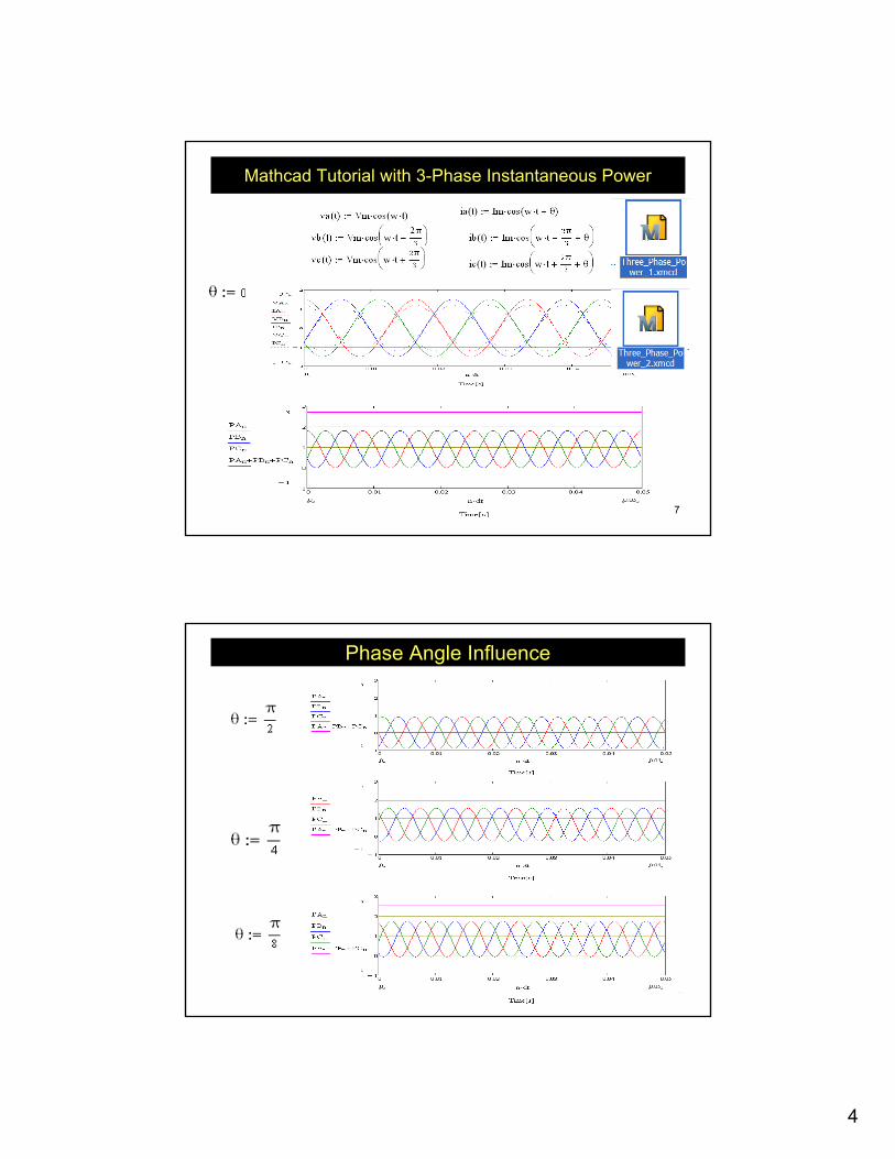
Mathcad Tutorial with 3-Phase Instantaneous Power
8
Phase Angle Influence
5
9
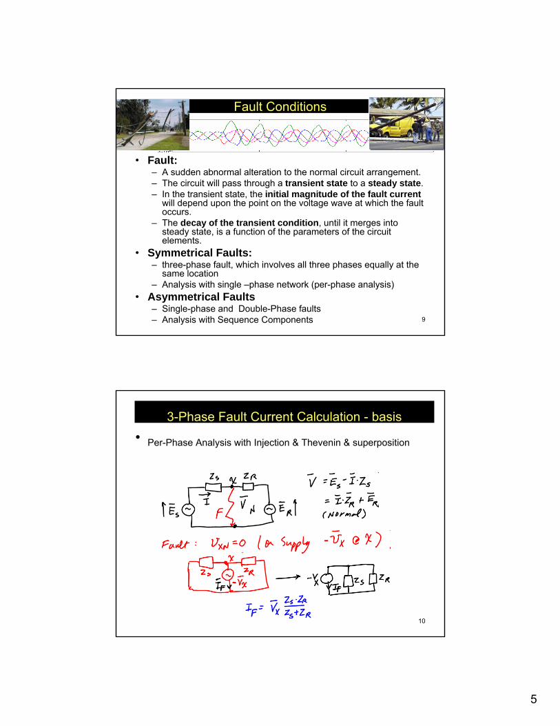
Fault Conditions
• Normal power system– balanced symmetrical three-phase network.
• Fault:– A sudden abnormal alteration to the normal circuit arrangement. – The circuit will pass through a transient state to a steady state. – In the transient state, the initial magnitude of the fault current
will depend upon the point on the voltage wave at which the fault occurs.
– The decay of the transient condition, until it merges into steady state, is a function of the parameters of the circuit elements.
• Symmetrical Faults:– three-phase fault, which involves all three phases equally at the
same location– Analysis with single –phase network (per-phase analysis)
• Asymmetrical Faults– Single-phase and Double-Phase faults– Analysis with Sequence Components
10
3-Phase Fault Current Calculation - basis• Per-Phase Analysis with Injection & Thevenin & superposition
6
11
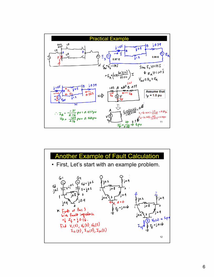
Practical Example
12
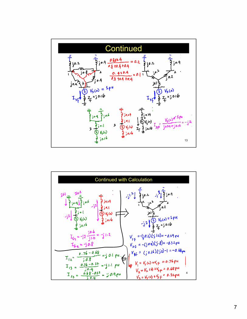
Another Example of Fault Calculation• First, Let’s start with an example problem.
7
13
Continued
14
Continued with Calculation
8
15
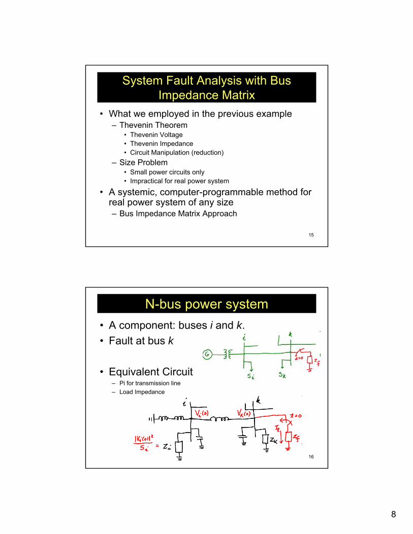
System Fault Analysis with Bus Impedance Matrix
• What we employed in the previous example– Thevenin Theorem
• Thevenin Voltage• Thevenin Impedance• Circuit Manipulation (reduction)
– Size Problem• Small power circuits only• Impractical for real power system
• A systemic, computer-programmable method for real power system of any size– Bus Impedance Matrix Approach
16
N-bus power system• A component: buses i and k.• Fault at bus k
• Equivalent Circuit– Pi for transmission line– Load Impedance
9
17
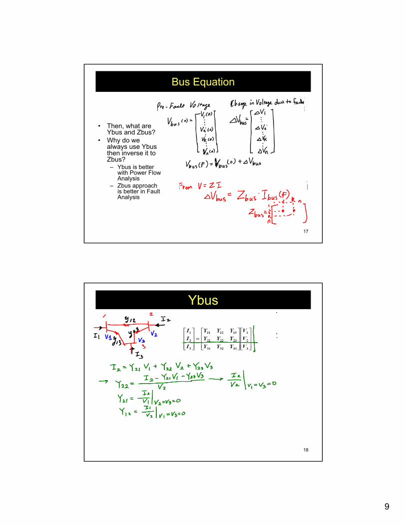
Bus Equation
• Then, what are Ybus and Zbus?
• Why do we always use Ybus, then inverse it to Zbus?– Ybus is better
with Power Flow Analysis
– Zbus approach is better in Fault Analysis
18
Ybus
10
19
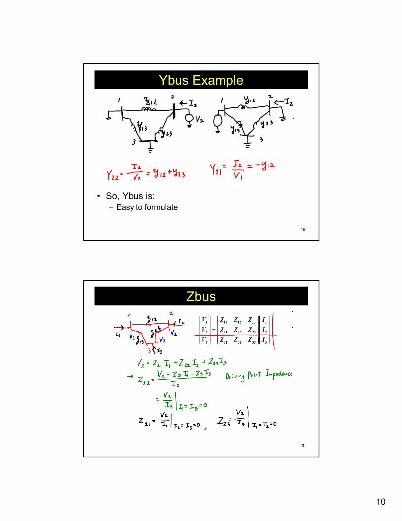
Ybus Example
• So, Ybus is:– Easy to formulate
20
Zbus
11
21
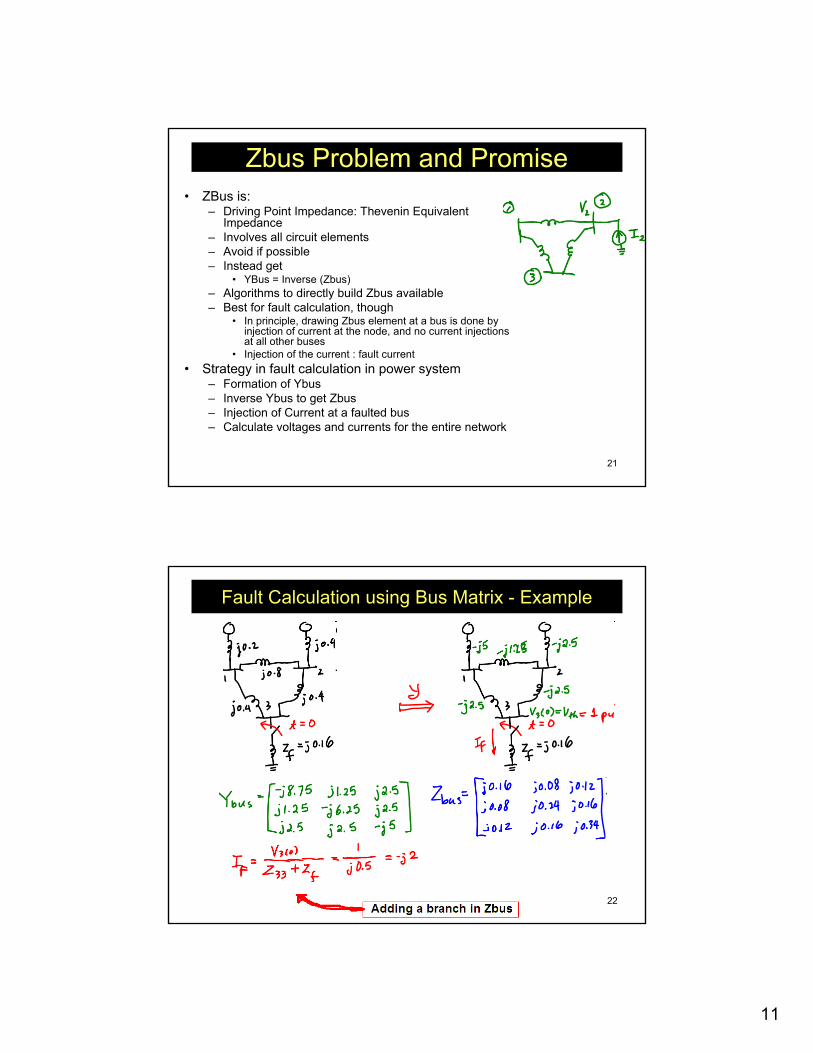
Zbus Problem and Promise• ZBus is:
– Driving Point Impedance: Thevenin Equivalent Impedance
– Involves all circuit elements– Avoid if possible– Instead get
• YBus = Inverse (Zbus)– Algorithms to directly build Zbus available– Best for fault calculation, though
• In principle, drawing Zbus element at a bus is done by injection of current at the node, and no current injections at all other buses
• Injection of the current : fault current• Strategy in fault calculation in power system
– Formation of Ybus– Inverse Ybus to get Zbus– Injection of Current at a faulted bus– Calculate voltages and currents for the entire network
22
Fault Calculation using Bus Matrix - Example
12
23
Voltage and Current
Calculation
24
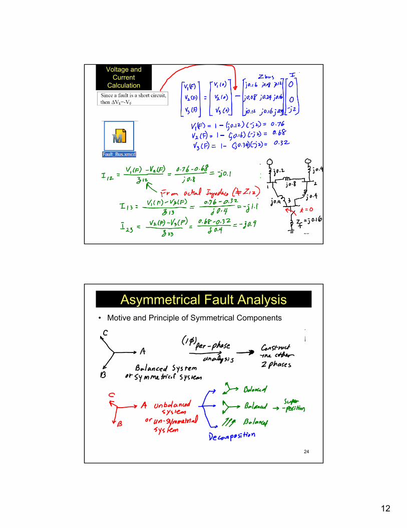
Asymmetrical Fault Analysis• Motive and Principle of Symmetrical Components
13
25
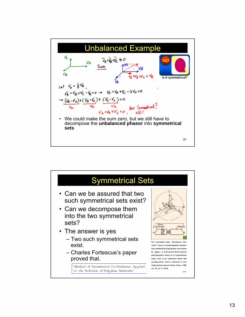
Unbalanced Example
• We could make the sum zero, but we still have to decompose the unbalanced phasor into symmetrical sets
26
Symmetrical Sets• Can we be assured that two
such symmetrical sets exist?• Can we decompose them
into the two symmetrical sets?
• The answer is yes– Two such symmetrical sets
exist. – Charles Fortescue’s paper
proved that.
14
27
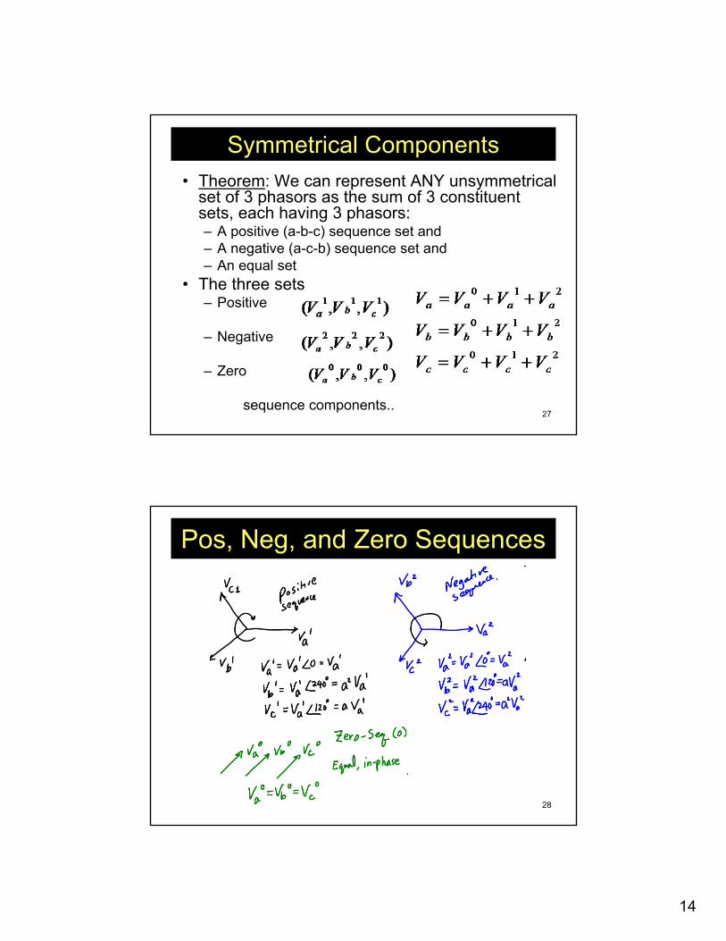
Symmetrical Components• Theorem: We can represent ANY unsymmetrical
set of 3 phasors as the sum of 3 constituent sets, each having 3 phasors:– A positive (a-b-c) sequence set and– A negative (a-c-b) sequence set and– An equal set
• The three sets– Positive
– Negative
– Zero
sequence components..
28
Pos, Neg, and Zero Sequences
15
29
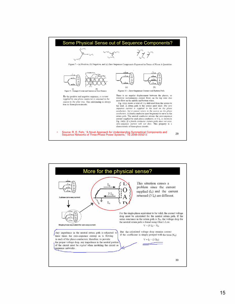
Some Physical Sense out of Sequence Components?
• Source: R. E. Fehr, “A Novel Approach for Understanding Symmetrical Components and Sequence Networks of Three-Phase Power Systems,” TE-2006-000213
30
More for the physical sense?
16
31
Matrix Form of Conversion
32
Sequence Impedance
17
33
Continued
34
Z012
• Off-diagonal terms =0 (Uncoupled)– the only current that determines the zero sequence voltage
is the zero sequence current.– the only current that determines the positive sequence
voltage is the positive sequence current.– the only current that determines the negative sequence
voltage is the negative sequence current.– 3 separate, distinct single phase equations
18
35
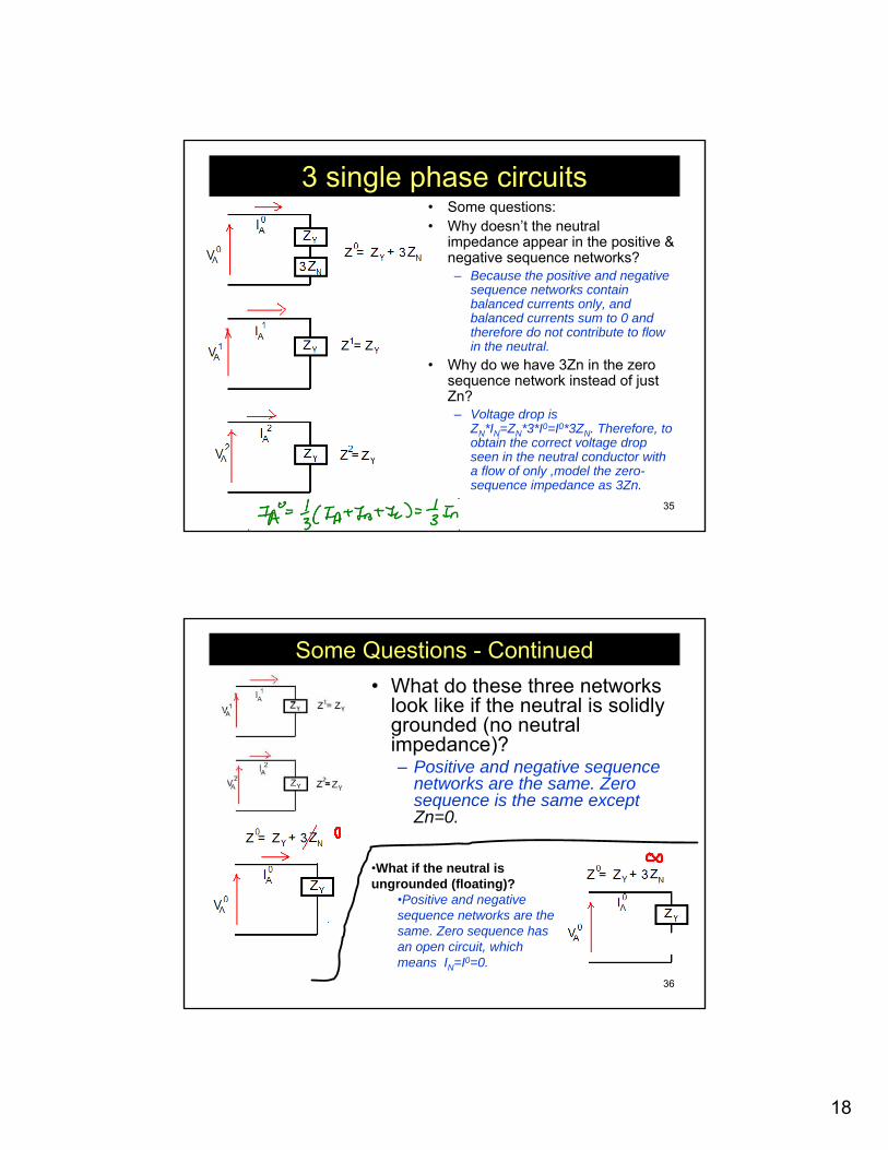
3 single phase circuits• Some questions:• Why doesn’t the neutral
impedance appear in the positive & negative sequence networks?– Because the positive and negative
sequence networks contain balanced currents only, and balanced currents sum to 0 and therefore do not contribute to flow in the neutral.
• Why do we have 3Zn in the zero sequence network instead of just Zn?– Voltage drop is
ZN*IN=ZN*3*I0=I0*3ZN. Therefore, to obtain the correct voltage drop seen in the neutral conductor with a flow of only ,model the zero-sequence impedance as 3Zn.
36
Some Questions - Continued• What do these three networks
look like if the neutral is solidly grounded (no neutral impedance)?– Positive and negative sequence
networks are the same. Zero sequence is the same exceptZn=0.
•What if the neutral is ungrounded (floating)?
•Positive and negative sequence networks are the same. Zero sequence has an open circuit, which means IN=I0=0.
19
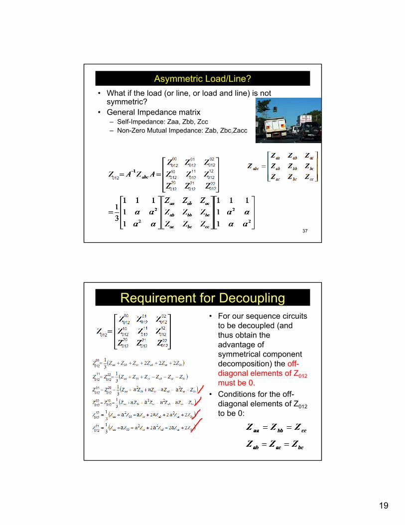
37
Asymmetric Load/Line?• What if the load (or line, or load and line) is not
symmetric? • General Impedance matrix
– Self-Impedance: Zaa, Zbb, Zcc– Non-Zero Mutual Impedance: Zab, Zbc,Zacc
38
Requirement for Decoupling• For our sequence circuits
to be decoupled (and thus obtain the advantage of symmetrical component decomposition) the off-diagonal elements of Z012must be 0.
• Conditions for the off-diagonal elements of Z012to be 0:
20
39
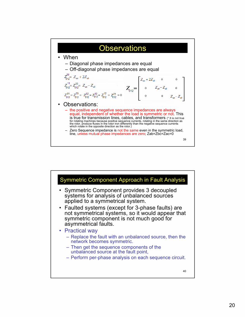
Observations• When
– Diagonal phase impedances are equal – Off-diagonal phase impedances are equal
• Observations:– the positive and negative sequence impedances are always
equal, independent of whether the load is symmetric or not. This is true for transmission lines, cables, and transformers. (* It is not true for rotating machines because positive sequence currents, rotating in the same direction as the rotor, produce fluxes in the rotor iron differently than the negative sequence currents which rotate in the opposite direction as the rotor.)
– Zero Sequence impedance is not the same even in the symmetric load, line, unless mutual phase impedances are zero; Zab=Zbc=Zac=0
40
Symmetric Component Approach in Fault Analysis
• Symmetric Component provides 3 decoupled systems for analysis of unbalanced sources applied to a symmetrical system.
• Faulted systems (except for 3-phase faults) are not symmetrical systems, so it would appear that symmetric component is not much good for asymmetrical faults.
• Practical way– Replace the fault with an unbalanced source, then the
network becomes symmetric.– Then get the sequence components of the
unbalanced source at the fault point, – Perform per-phase analysis on each sequence circuit.
21
41
Developing Sequence Networks for Fault Analysis
• (1) Develop the sequence network for the system under analysis.– Express abc voltages as a function of abc currents and abc
impedances.– Substitute symmetric components for abc voltages and currents
(e.g., Vabc=AV012 and Iabc=AI012).– Manipulate to obtain the form V012=Z012*I012.– Obtain the Thevenin equivalents looking into the network from
the fault point.• (2) Connect the Sequence Networks to capture the
influence of the particular fault type.• (3)Compute the Sequence fault current from the circuit
resulting from step 2.• (4) Compute the phase currents Ia, Ib, and Ic from
Iabc=A*I012.
42
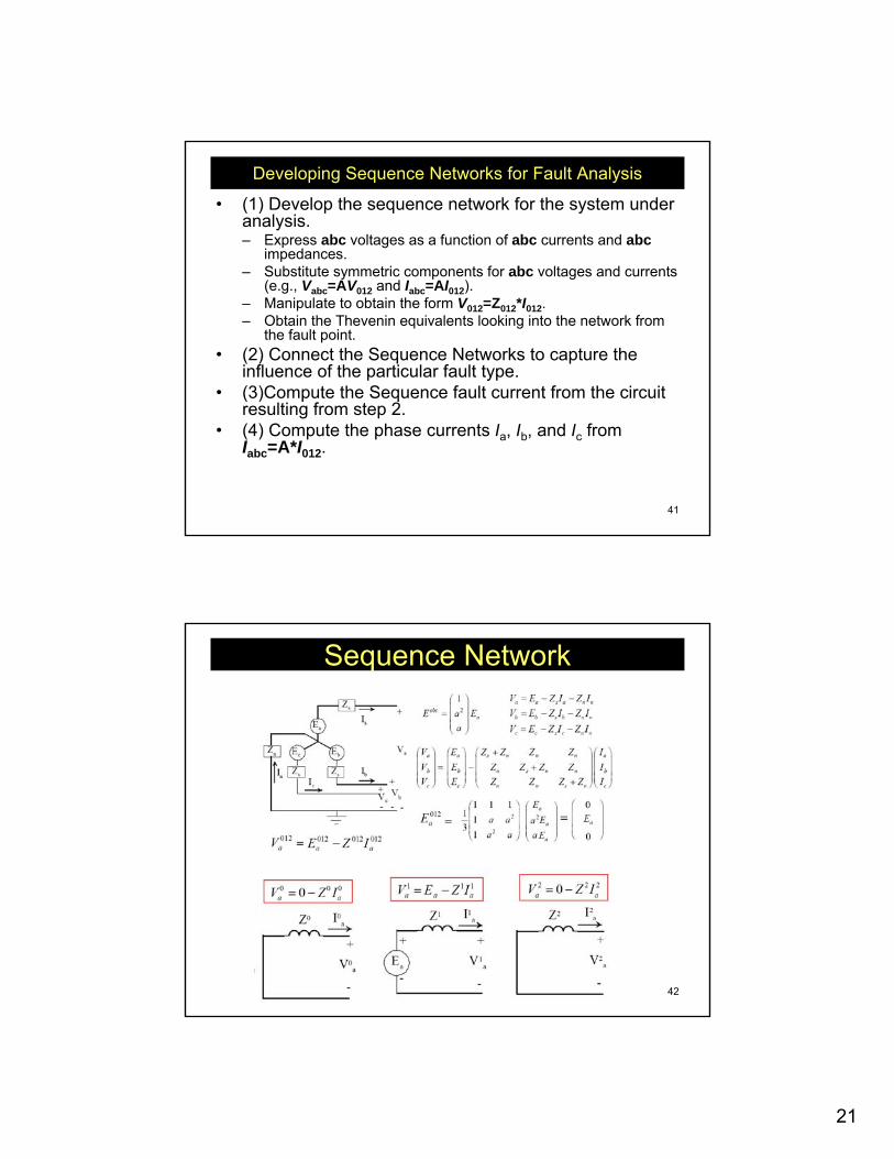
Sequence Network
22
43
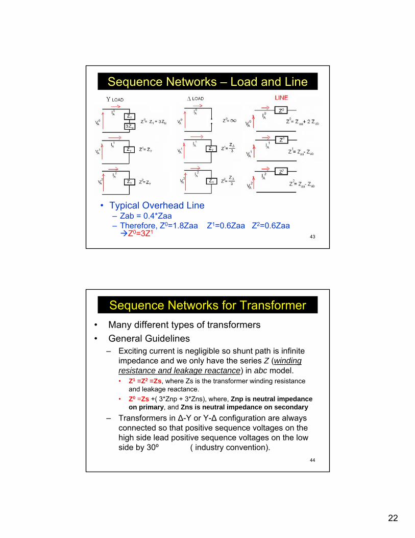
Sequence Networks – Load and Line
• Typical Overhead Line– Zab = 0.4*Zaa– Therefore, Z0=1.8Zaa Z1=0.6Zaa Z2=0.6Zaa
Z0=3Z1
44
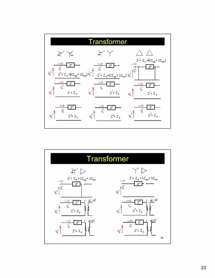
Sequence Networks for Transformer• Many different types of transformers• General Guidelines
– Exciting current is negligible so shunt path is infinite impedance and we only have the series Z (winding resistance and leakage reactance) in abc model.• Z1 =Z2 =Zs, where Zs is the transformer winding resistance
and leakage reactance.• Z0 =Zs +( 3*Znp + 3*Zns), where, Znp is neutral impedance
on primary, and Zns is neutral impedance on secondary– Transformers in Δ-Y or Y-Δ configuration are always
connected so that positive sequence voltages on the high side lead positive sequence voltages on the low side by 30º ( industry convention).
23
45
Transformer
46
Transformer
24
47
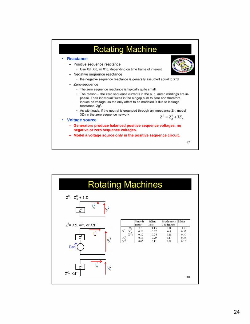
Rotating Machine• Reactance
– Positive sequence reactance• Use Xd, X’d, or X’’d, depending on time frame of interest.
– Negative sequence reactance• the negative sequence reactance is generally assumed equal to X’’d.
– Zero-sequence• The zero sequence reactance is typically quite small.• The reason - the zero sequence currents in the a, b, and c windings are in-
phase. Their individual fluxes in the air gap sum to zero and therefore induce no voltage, so the only effect to be modeled is due to leakage reactance, Zg0.
• As with loads, if the neutral is grounded through an impedance Zn, model 3Zn in the zero sequence network
• Voltage source– Generators produce balanced positive sequence voltages, no
negative or zero sequence voltages. – Model a voltage source only in the positive sequence circuit.
48
Rotating Machines
25
49
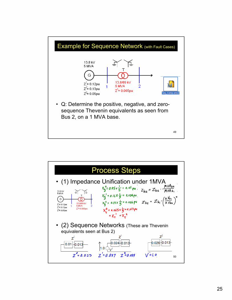
Example for Sequence Network (with Fault Cases)
• Q: Determine the positive, negative, and zero-sequence Thevenin equivalents as seen from Bus 2, on a 1 MVA base.
50
Process Steps• (1) Impedance Unification under 1MVA
• (2) Sequence Networks (These are Theveninequivalents seen at Bus 2)
26
51
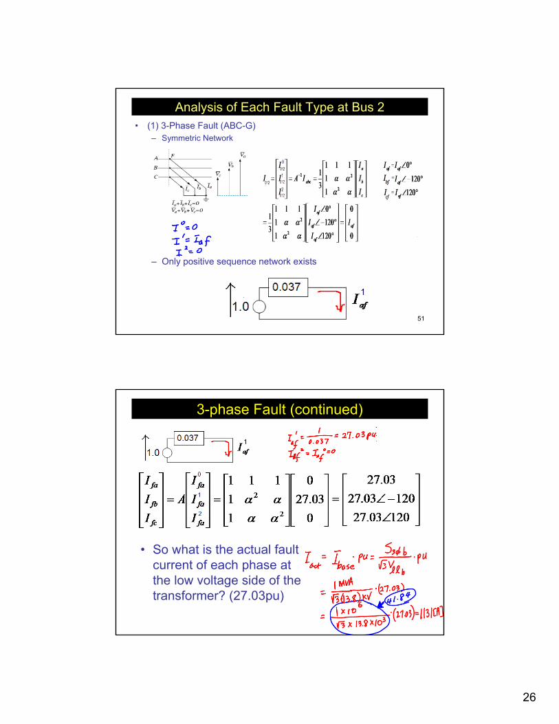
Analysis of Each Fault Type at Bus 2• (1) 3-Phase Fault (ABC-G)
– Symmetric Network
– Only positive sequence network exists
52
3-phase Fault (continued)
• So what is the actual fault current of each phase at the low voltage side of the transformer? (27.03pu)
27
53
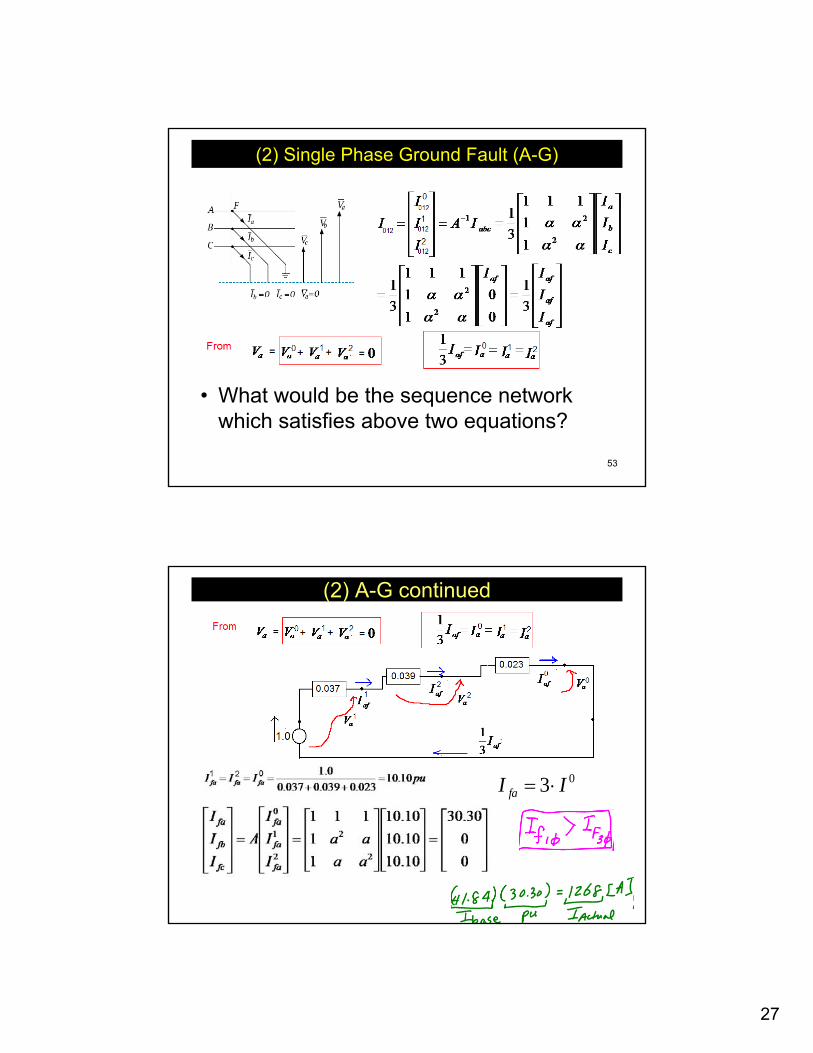
(2) Single Phase Ground Fault (A-G)
• What would be the sequence network which satisfies above two equations?
54
(2) A-G continued
03 II fa ⋅=
28
55
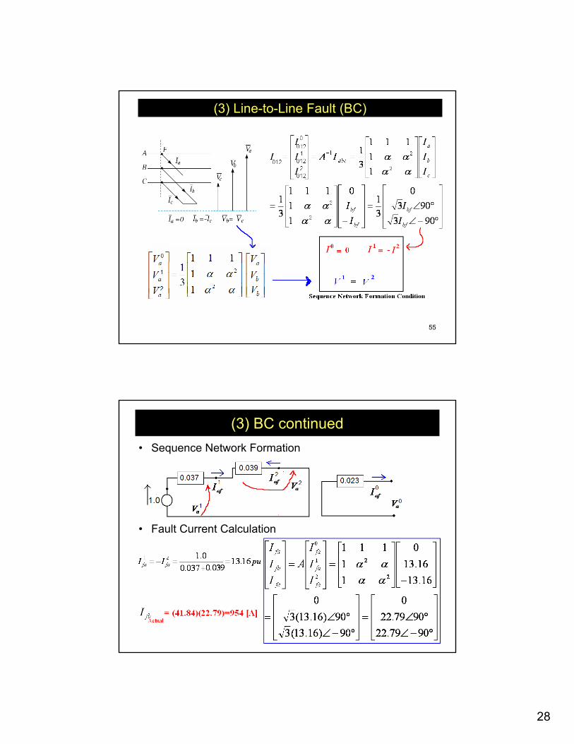
(3) Line-to-Line Fault (BC)
56
(3) BC continued• Sequence Network Formation
• Fault Current Calculation
29
57
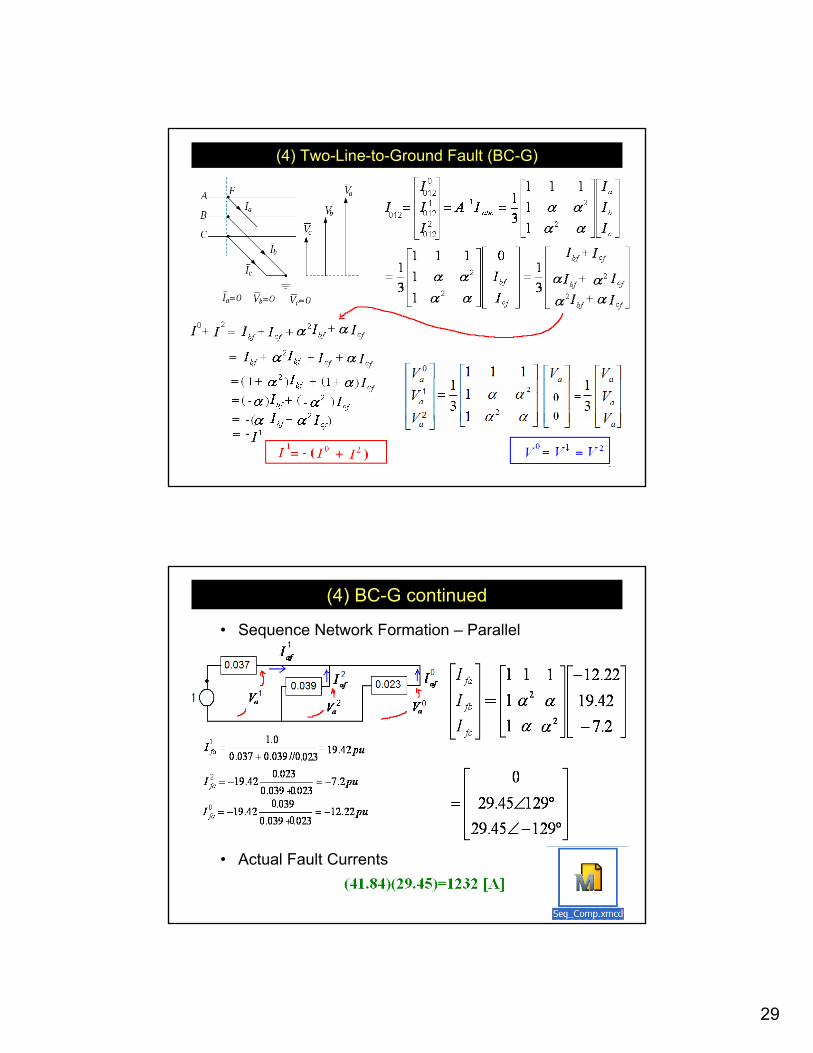
(4) Two-Line-to-Ground Fault (BC-G)
58
(4) BC-G continued
• Sequence Network Formation – Parallel
• Actual Fault Currents
30
59
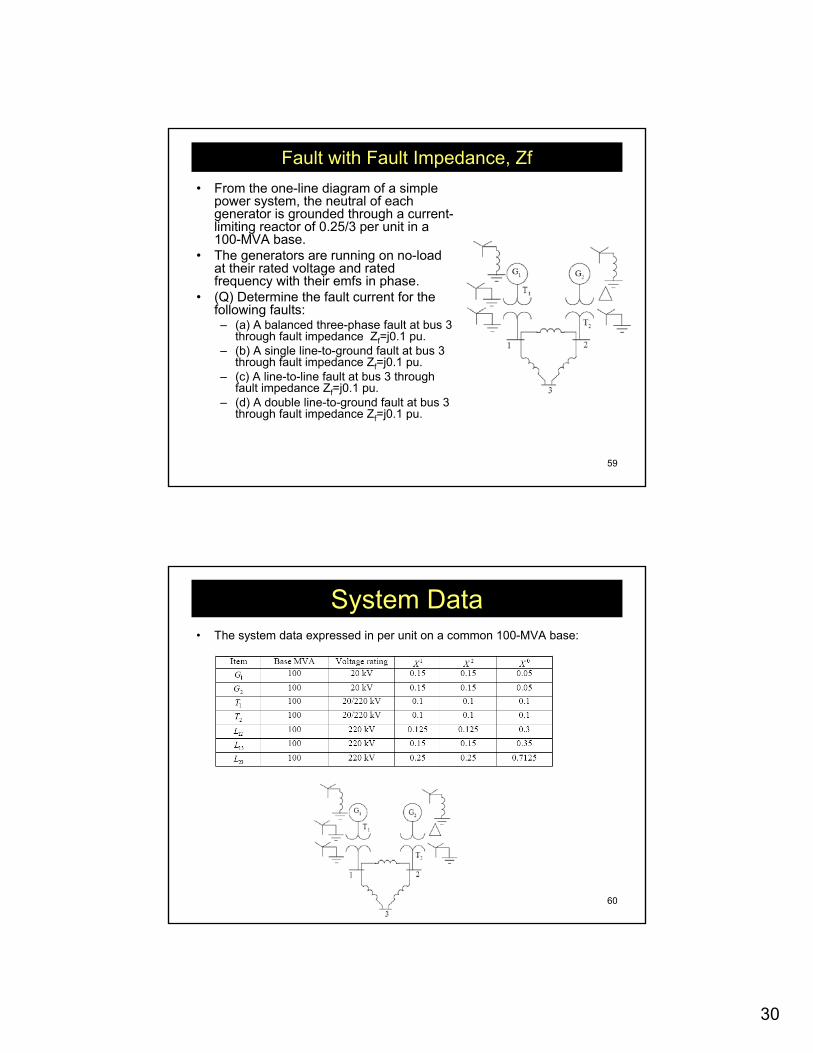
Fault with Fault Impedance, Zf• From the one-line diagram of a simple
power system, the neutral of each generator is grounded through a current-limiting reactor of 0.25/3 per unit in a 100-MVA base.
• The generators are running on no-load at their rated voltage and rated frequency with their emfs in phase.
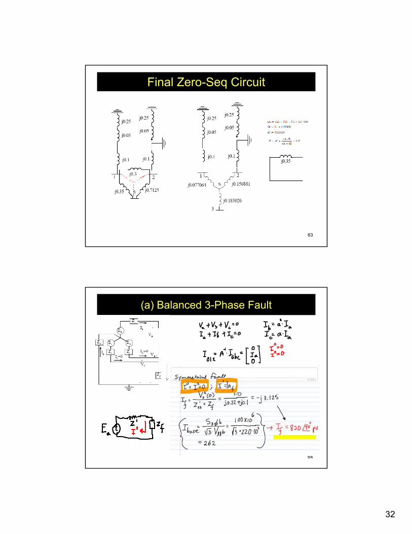
• (Q) Determine the fault current for the following faults:– (a) A balanced three-phase fault at bus 3
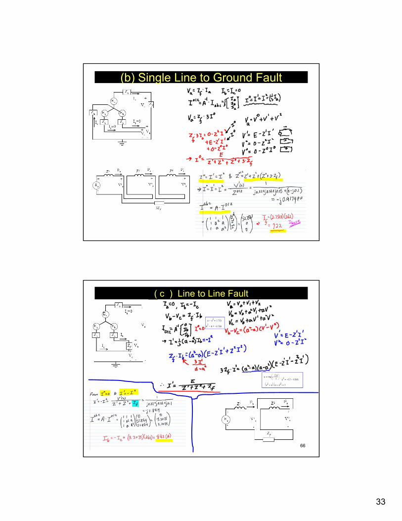
through fault impedance Zf=j0.1 pu.– (b) A single line-to-ground fault at bus 3
through fault impedance Zf=j0.1 pu.– (c) A line-to-line fault at bus 3 through
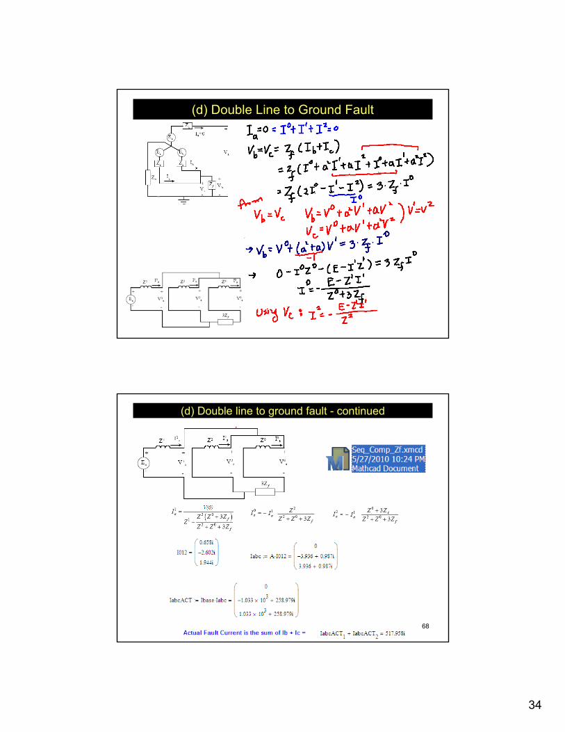
fault impedance Zf=j0.1 pu.– (d) A double line-to-ground fault at bus 3
through fault impedance Zf=j0.1 pu.
60
System Data• The system data expressed in per unit on a common 100-MVA base:
31
61
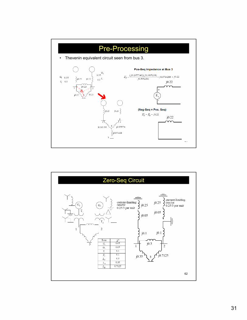
Pre-Processing• Thevenin equivalent circuit seen from bus 3.
62
Zero-Seq Circuit
32
63
Final Zero-Seq Circuit
64
(a) Balanced 3-Phase Fault
33
65
(b) Single Line to Ground Fault
66
( c ) Line to Line Fault
34
67
(d) Double Line to Ground Fault
68
(d) Double line to ground fault - continued
35
69
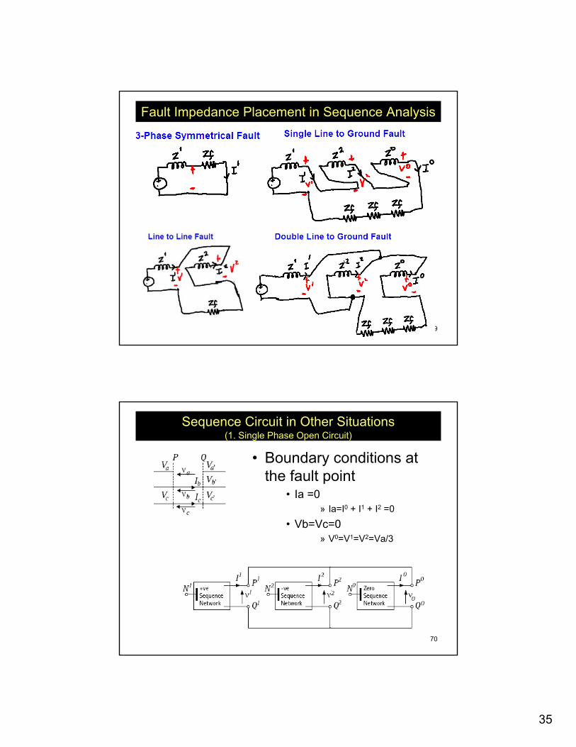
Fault Impedance Placement in Sequence Analysis
70
Sequence Circuit in Other Situations(1. Single Phase Open Circuit)
• Boundary conditions at the fault point
• Ia =0» Ia=I0 + I1 + I2 =0
• Vb=Vc=0» V0=V1=V2=Va/3
36
71
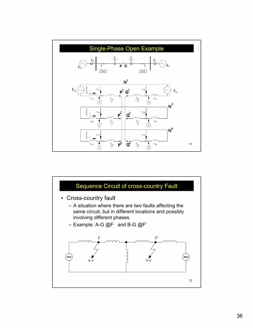
Single-Phase Open Example
72
Sequence Circuit of cross-country Fault
• Cross-country fault– A situation where there are two faults affecting the
same circuit, but in different locations and possibly involving different phases.
– Example: A-G @F and B-G @F’
37
73
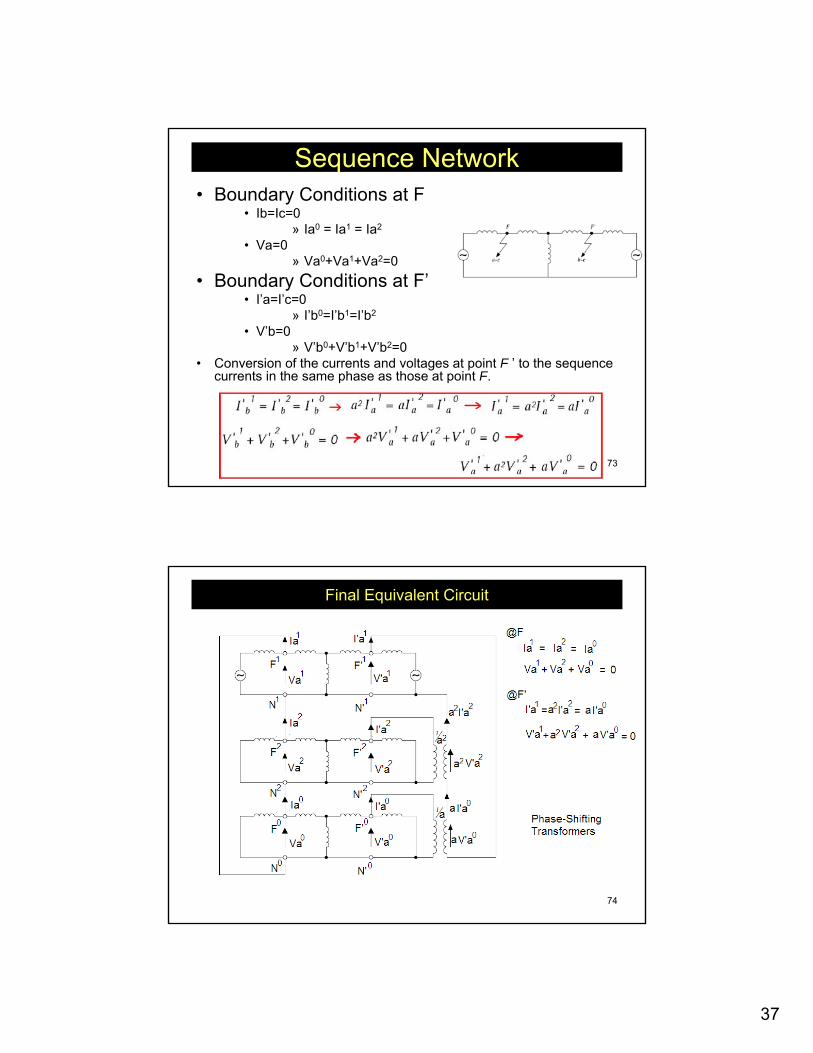
Sequence Network• Boundary Conditions at F
• Ib=Ic=0» Ia0 = Ia1 = Ia2
• Va=0» Va0+Va1+Va2=0
• Boundary Conditions at F’• I’a=I’c=0
» I’b0=I’b1=I’b2
• V’b=0» V’b0+V’b1+V’b2=0
• Conversion of the currents and voltages at point F ’ to the sequence currents in the same phase as those at point F.
74
Final Equivalent Circuit
38
75
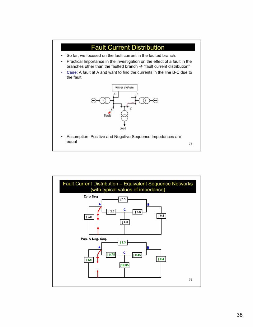
Fault Current Distribution• So far, we focused on the fault current in the faulted branch.• Practical Importance in the investigation on the effect of a fault in the
branches other than the faulted branch “fault current distribution”• Case: A fault at A and want to find the currents in the line B-C due to
the fault.
• Assumption: Positive and Negative Sequence Impedances are equal
76
Fault Current Distribution – Equivalent Sequence Networks (with typical values of impedance)
39
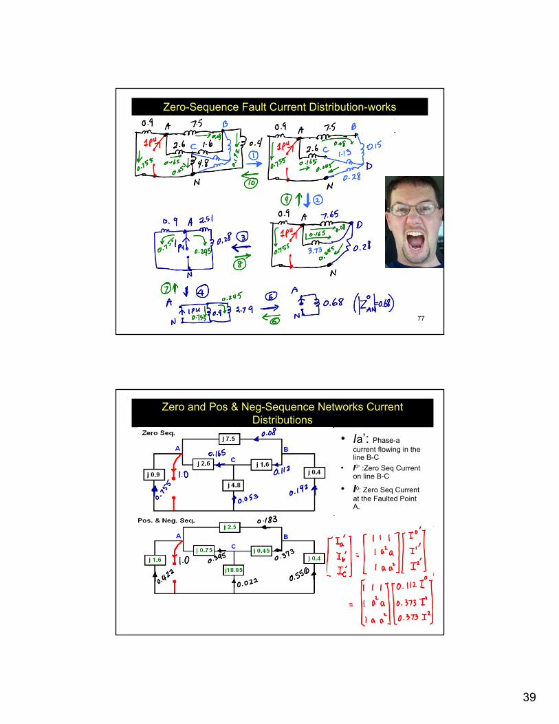
77
Zero-Sequence Fault Current Distribution-works
78
Zero and Pos & Neg-Sequence Networks Current Distributions
• Ia’: Phase-a current flowing in the line B-C
• I0’ :Zero Seq Current on line B-C
• I0: Zero Seq Current at the Faulted Point A.
40
79
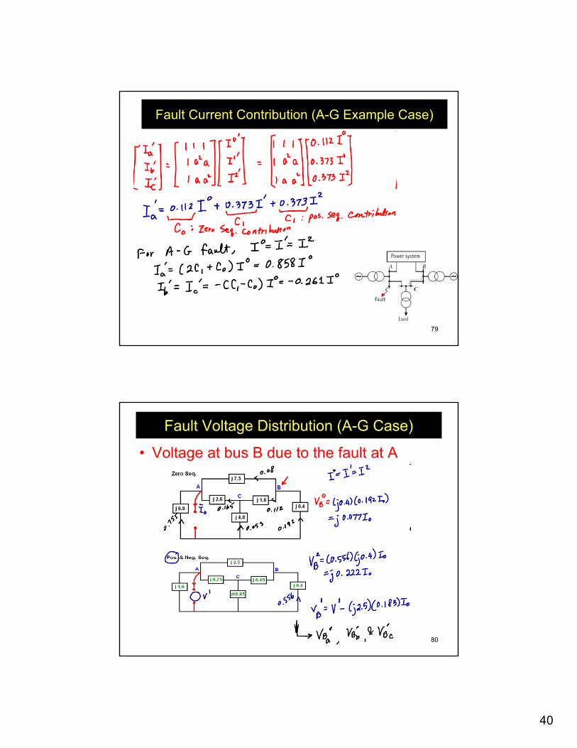
Fault Current Contribution (A-G Example Case)
80
Fault Voltage Distribution (A-G Case)
• Voltage at bus B due to the fault at A
41
81
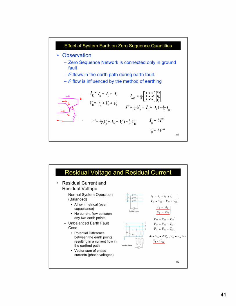
Effect of System Earth on Zero Sequence Quantities
• Observation– Zero Sequence Network is connected only in ground
fault– I0 flows in the earth path during earth fault. – I0 flow is influenced by the method of earthing
82
Residual Voltage and Residual Current• Residual Current and
Residual Voltage– Normal System Operation
(Balanced)• All symmetrical (even
capacitance)• No current flow between
any two earth points– Unbalanced Earth Fault
Case• Potential Difference
between the earth points, resulting in a current flow in the earthed path
• Vector sum of phase currents (phase voltages)
42
83
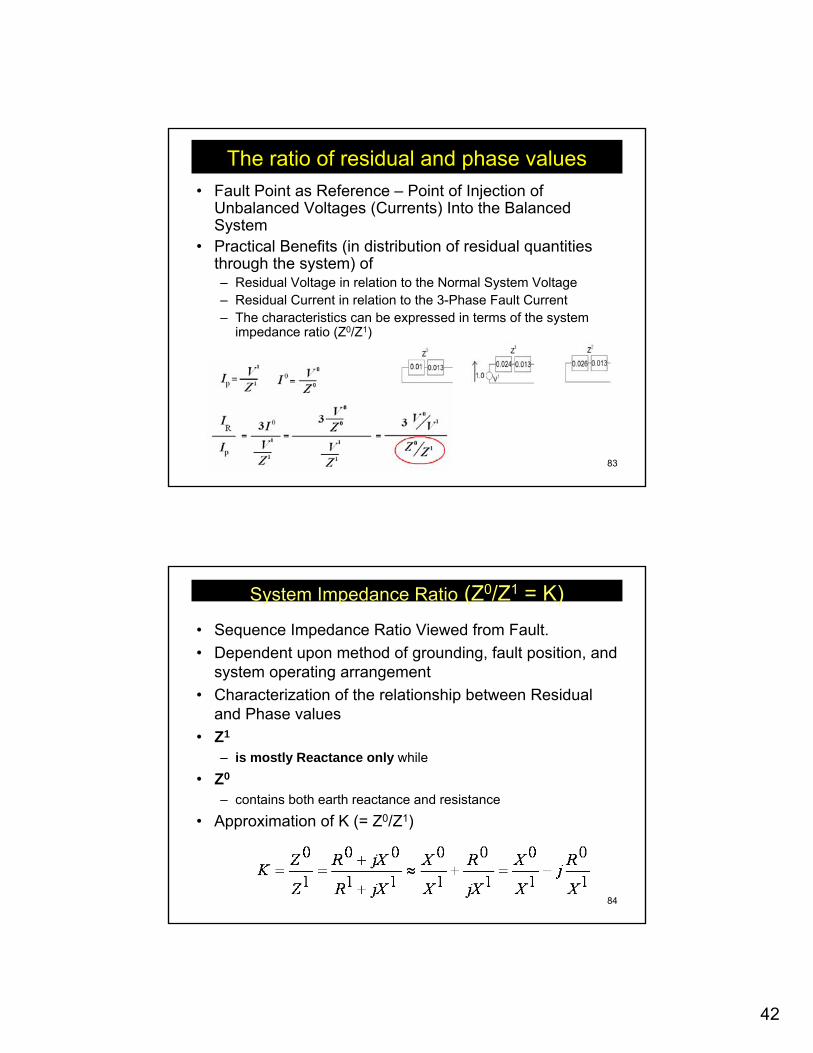
The ratio of residual and phase values• Fault Point as Reference – Point of Injection of
Unbalanced Voltages (Currents) Into the Balanced System
• Practical Benefits (in distribution of residual quantities through the system) of– Residual Voltage in relation to the Normal System Voltage– Residual Current in relation to the 3-Phase Fault Current– The characteristics can be expressed in terms of the system
impedance ratio (Z0/Z1)
84
System Impedance Ratio (Z0/Z1 = K)• Sequence Impedance Ratio Viewed from Fault.• Dependent upon method of grounding, fault position, and
system operating arrangement• Characterization of the relationship between Residual
and Phase values• Z1
– is mostly Reactance only while
• Z0
– contains both earth reactance and resistance
• Approximation of K (= Z0/Z1)
43
85
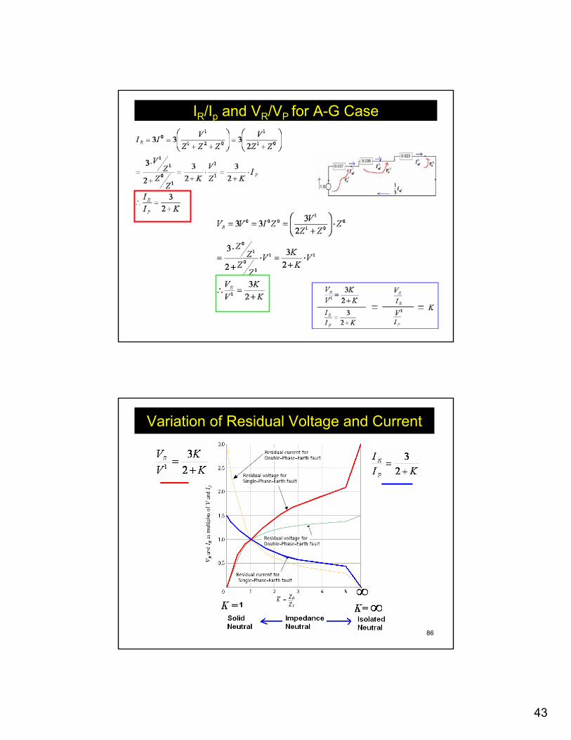
IR/Ip and VR/VP for A-G Case
86
Variation of Residual Voltage and Current
44
87
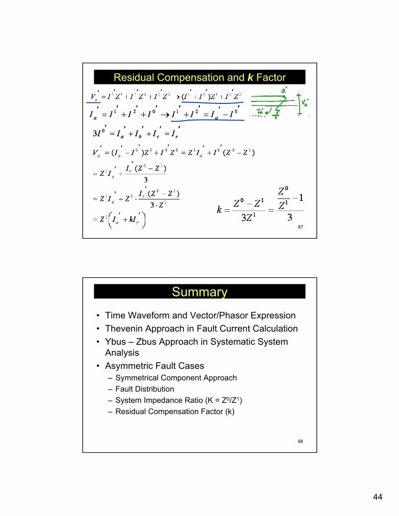
Residual Compensation and k Factor
88
Summary
• Time Waveform and Vector/Phasor Expression• Thevenin Approach in Fault Current Calculation• Ybus – Zbus Approach in Systematic System
Analysis• Asymmetric Fault Cases
– Symmetrical Component Approach– Fault Distribution– System Impedance Ratio (K = Z0/Z1)– Residual Compensation Factor (k)