Embed Size (px)
Citation preview
FB15, FB25, FB35, FB40, FB50
Glass Passivated Single-Phase Bridge Rectifier
www.fagorelectronica.comDocument Name: fb-powerbridge
Version: Jan-18Page Number: 1 / 6
Revision: 2
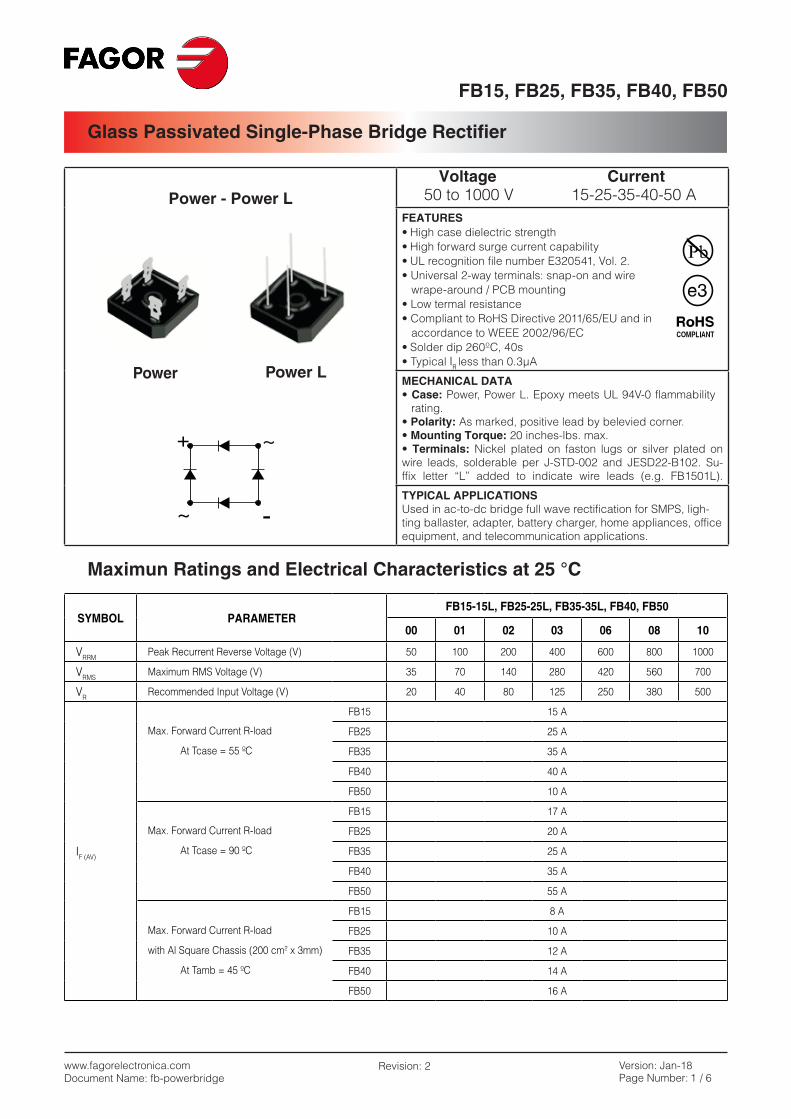
Power - Power L Voltage Current 50 to 1000 V 15-25-35-40-50 A
FEATURES• High case dielectric strength• High forward surge current capability• UL recognition file number E320541, Vol. 2.• Universal 2-way terminals: snap-on and wire wrape-around / PCB mounting• Low termal resistance• Compliant to RoHS Directive 2011/65/EU and in accordance to WEEE 2002/96/EC• Solder dip 260ºC, 40s• Typical IR less than 0.3µA
MECHANICAL DATA• Case: Power, Power L. Epoxy meets UL 94V-0 flammability
rating.• Polarity: As marked, positive lead by belevied corner.• Mounting Torque: 20 inches-lbs. max.• Terminals: Nickel plated on faston lugs or silver plated on wire leads, solderable per J-STD-002 and JESD22-B102. Su-ffix letter “L” added to indicate wire leads (e.g. FB1501L).
TYPICAL APPLICATIONSUsed in ac-to-dc bridge full wave rectification for SMPS, ligh-ting ballaster, adapter, battery charger, home appliances, office equipment, and telecommunication applications.
Maximun Ratings and Electrical Characteristics at 25 °C
SYMBOL PARAMETERFB15-15L, FB25-25L, FB35-35L, FB40, FB50
00 01 02 03 06 08 10
VRRMPeak Recurrent Reverse Voltage (V) 50 100 200 400 600 800 1000
VRMSMaximum RMS Voltage (V) 35 70 140 280 420 560 700
VRRecommended Input Voltage (V) 20 40 80 125 250 380 500
IF (AV)
FB15 15 A
Max. Forward Current R-load FB25 25 A
At Tcase = 55 ºC FB35 35 A
FB40 40 A
FB50 10 A
FB15 17 A
Max. Forward Current R-load FB25 20 A
At Tcase = 90 ºC FB35 25 A
FB40 35 A
FB50 55 A
FB15 8 A
Max. Forward Current R-load FB25 10 A
with Al Square Chassis (200 cm2 x 3mm) FB35 12 A
At Tamb = 45 ºC FB40 14 A
FB50 16 A
FB15, FB25, FB35, FB40, FB50
Glass Passivated Single-Phase Bridge Rectifier
www.fagorelectronica.comDocument Name: fb-powerbridge
Version: Jan-18Page Number: 2 / 6
Revision: 2
Maximum Ratings and Electrical Characteristics at 25 °C
Electrical Characteristics at Tamb = 25 °C
SYMBOL PARAMETERFB15-15L, FB25-25L, FB35-35L, FB40, FB50
00 01 02 03 06 08 10
IFRM
FB15 60 A
FB25 75 A
Recurrent peak forward current FB35 75 A
FB40 100 A
FB50 100 A
IFSM
FB15 300 A
FB25 300 A
10 ms. Peak forward surge current FB35 400 A
FB40 400 A
FB50 400 A
I2t
FB15 450 A2sec
FB25 450 A2sec
I2t value for fusing (t = 10 ms) FB35 800 A2sec
FB40 800 A2sec
FB50 800 A2sec
Tj Operating Temperature Range -55 to + 150 ºC
Tstg Storage Temperature Range -55 to + 150 ºC
VF
IF = 7.5 A FB15 1.1 V
Max. Forward voltage drop per IF =12.5 A FB25 1.1 V
element at IF = 17.5 A FB35 1.1 V
IF = 20 A FB40 1.1 V
IF = 25 A FB50 1.1 V
IR Max. Reverse current per element at VRRM 5mA
Rthj-c
Typical Thermal resistance junction to case (Note 1) 1.5 ºC/W
Isolation voltage from case to leads 2500 Vac
(Note 1) With heatsink
FB15, FB25, FB35, FB40, FB50
Glass Passivated Single-Phase Bridge Rectifier
www.fagorelectronica.comDocument Name: fb-powerbridge
Version: Jan-18Page Number: 3 / 6
Revision: 2
PREFERRED P/N PACKAGE CODE DELIVERY MODE BASE QUANTITY UNIT WEIGHT (g)
FB2502 POWER BOX POWER 50 16.5
FB2502L POWER BOX POWER L 50 15.6
FB5002 POWER BOX POWER 50 14.5
Ordering information
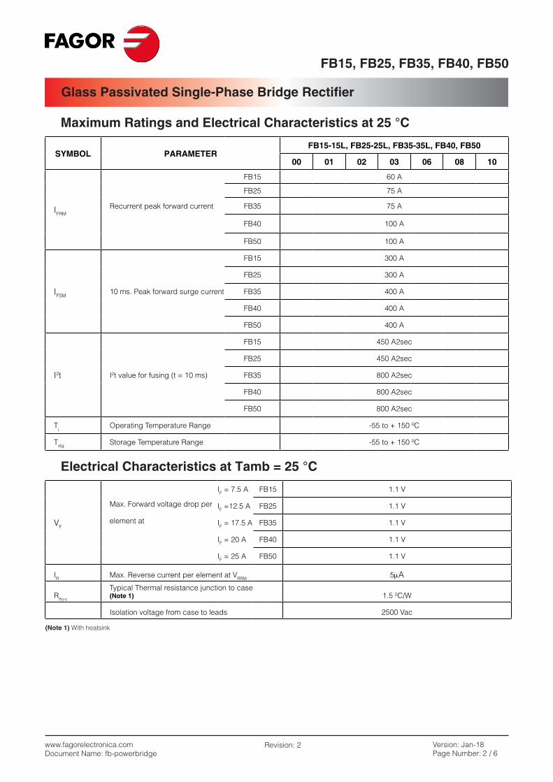
Package Outline Dimensions: (mm) Power - Power L
15÷35 A40÷50 A20.519
FB15, FB25, FB35, FB40, FB50
Glass Passivated Single-Phase Bridge Rectifier
www.fagorelectronica.comDocument Name: fb-powerbridge
Version: Jan-18Page Number: 4 / 6
Revision: 2
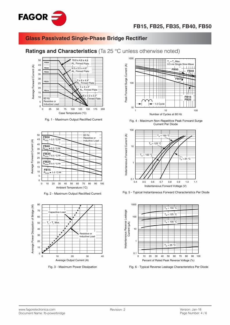
Ratings and Characteristics (Ta 25 °C unless otherwise noted)
FB15, FB25, FB35, FB40, FB50
Glass Passivated Single-Phase Bridge Rectifier
www.fagorelectronica.comDocument Name: fb-powerbridge
Version: Jan-18Page Number: 5 / 6
Revision: 2
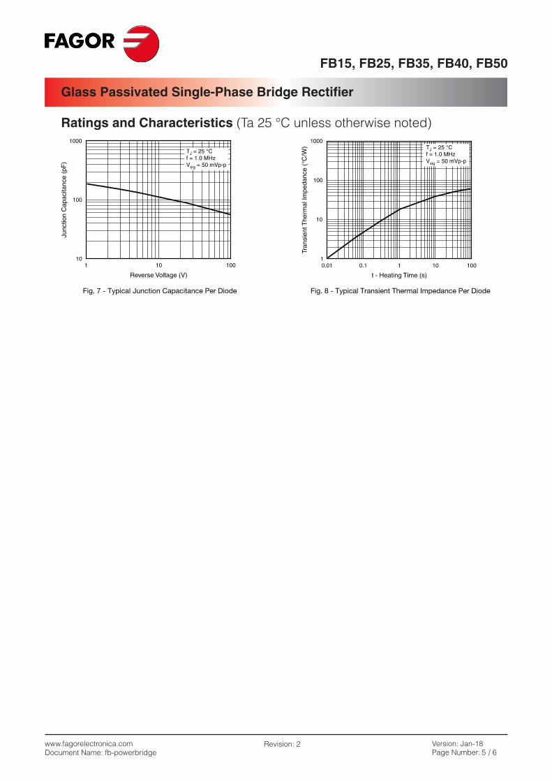
Ratings and Characteristics (Ta 25 °C unless otherwise noted)
FB15, FB25, FB35, FB40, FB50
Glass Passivated Single-Phase Bridge Rectifier
www.fagorelectronica.comDocument Name: fb-powerbridge
Version: Jan-18Page Number: 6 / 6
Revision: 2
Revision History
DATE REVISION DESCRIPTION OF CHANGES
11-Sep-2012 0 Original Data Sheet
20-Jul-2016 1 Eliminate Power-M family and general review
24-Jan-2018 2 Total height dimension clarified
DisclaimerAll product, product specifications and data are subject to change without notice to improve reliability, function or design or otherwise.
Fagor Electrónica, S. Coop., its affiliates, agents, and employees, and all persons acting on its or their behalf (collectively, “Fagor”), disclaim any and all liability for any errors, inaccuracies or incompleteness contained in any datasheet or in any other disclosure relating to any product.
Fagor makes no warranty, representation or guarantee regarding the suitability of the products for any particular purpose or the continuing production of any product. To the maximum extent permitted by applicable law, Fagor disclaims (i) any and all liability arising out of the application or use of any product, (ii) any and all liability, including without limitation special, consequential or in-cidental damages, and (iii) any and implied warranties, including warranties of fitness for particular purpose, non-infringement and merchantability.
Statements regarding the suitability of products for certain types of applications are based on Fagor’s knowledge of typical requi-rements that are often placed on Fagor products in generic applications. Such statements are not binding statements about the suitability of products for a particular application. It is the cutomer’s responsibility to validate that a particular product with the pro-perties described in the product specification is suitable for use in a particular application. Parameters provided in datasheets and/or specifications may vary in different applications and performance may vary over time. All operating parameters, including typical parameters, must be validated for each customer application by the customer’s technical experts. Product specifications do not expand or otherwise modify Fagor’s terms and conditions or purchase, including but not limited to the warranty expressed therein.
Except as expressly indicated in writing. Fagor products are not designed for use in medical, life-saving, or life-sustaining applica-tions or for any other application in which the failure of the Fagor product could result in personal injury or death. Customers using or selling Fagor products not expressly indicated for use in such applications do so at their own risk and agree to fully indemnify and hold Fagor and its distributors harmless from and against any and all claims, liabilities, expenses and damages arising or resulting in connection with such use or sale, including attomeys fees, even if such claim alleges that Fagor or its distributor was negligent regarding the design or manufacture of the part. Please contact authorized Fagor personnel to obtain written terms and conditions regarding products designed for such applications.
No license, express or implied, by estoppel or otherwise, to any intellectual property rights is granted by this document or by any conduct of Fagor. Products names and markings noted herein may be trademarks of their respective owners.


![Untitled-1 [] · FB20-7 3450 3495 3510 3540 3565 3580 3600 3665 3710 3750 Overall Mast l£ght (3)Free lift Service Weight (with battery) FB30-7 FB25-7 FB25-7LB FB25-7V Capacity at](https://img.pdfslide.net/doc/110x75/60dead27fd28d006400d3d9a/untitled-1-fb20-7-3450-3495-3510-3540-3565-3580-3600-3665-3710-3750-overall.jpg)
![SPECIFICATION - Truckutleie · © Mitsubishi Forklift Trucks 2017. All rights reserved. 7 (34) FB25-35(C)N Specification Manual 4.3 Free lift (see tables) h2 [mm] 100 100 100 100](https://img.pdfslide.net/doc/110x75/614a802612c9616cbc6974ce/specification-truckutleie-mitsubishi-forklift-trucks-2017-all-rights-reserved.jpg)