Embed Size (px)
Citation preview

CAD/GIS Interoperability
Rebecca Barber
Geographic Mapping Specialist
Presentation Overview
Background
Research
Interoperability
Examples
Drafting GIS Features in MicroStation
Processing Parcel Line Work
Interoperability Tools
Beta Testing
Summary
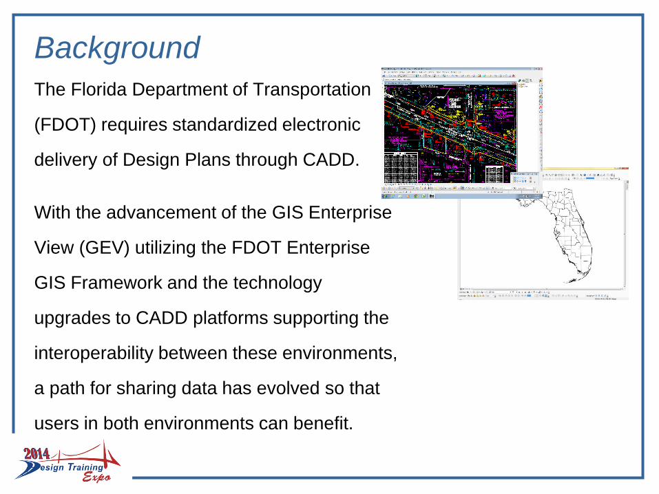
Background
The Florida Department of Transportation
(FDOT) requires standardized electronic
delivery of Design Plans through CADD.
With the advancement of the GIS Enterprise
View (GEV) utilizing the FDOT Enterprise
GIS Framework and the technology
upgrades to CADD platforms supporting the
interoperability between these environments,
a path for sharing data has evolved so that
users in both environments can benefit.
Background
In 2011 FDOT started looking for a way to put everything Right of Way (ROW) related into the new enterprise GIS framework looking backward to historic records
There was some success in manipulating the CADD line work for ROW acquisitions into a GIS environment, but the work was tedious and time consuming
Utilities (a highly desired data set) would be even more tedious
Research
Texas A&M Transportation Institute (TTI) was brought in to examine FDOTs current system, practices and processes
To develop a strategic implementation plan that would manage ROW parcels and utility data
Including a process, workflow and a tool to hopefully “automate” bringing this historical data (CADD line work) into a GIS environment and to give it intelligence
This research project was completed in May of 2013
Research Overview
They conducted site visits and collected CADD Files and
Documents. From this they developed
- lists of levels, cells, and attributes
- database tables, routines, and menus, to extract CADD
information desirable to the GIS environment
Recommendations:
Use of existing survey and GEOPAK data to generate parcel
shapes
Use a database approach for managing design libraries and
levels in MicroStation to be able to
- link information
- and add attribute data
Created steps for integrating existing parcel and utility data into
FDOT’s enterprise GIS framework
Research
But, there is no true “automation” available
There is too much drafting cleanup needed on the historical data
So getting the historical data into a GIS environment will be mostly manual, even with the tools developed by TTI
So where do we go from here?
We can began to gather new data,
while trying to come up with a plan for the old data
Interoperability
What does that mean?
It means that you can take line work from a CADD application, give it intelligence and export it into a GIS application
Or take intelligent data from a GIS application and import it into a CADD application
Since this data has intelligence you can do queries, its not just about turning off layers/levels
- Say you only want to see roadways that have a speed limit of 55mph.....you can do that
- Or say you only want to see parcels over/under a certain acreage...you can do that too
Interoperability FDOT anticipates that one day the ability to reference all or some amount of
historical layers such as
Survey Control,
Parcels,
Aerials,
ROW,
Roadway,
Easements,
Utilities, and Permit Agreements
In both CADD and GIS platforms
FDOT sees this information as having great value in areas of informed decision
making or maybe even those creating high amounts of public record requests
Technology is moving in that direction with both the Bentley and AutoCAD
platforms now supporting importing and exporting of GIS data
Interoperability
So…..
How can we integrate CADD Survey/Engineering
data that’s symbolized specifically to create a set
of design plans for construction so that elements
of that design can be visualized/attributed and
thereby successfully used in a Geographic
Information System?
Interoperability
Before we can begin to answer that question we must first have an understanding of what it is that GIS requires in order to visualize and geospatially query information
GIS uses relational tables of records that are geospatially aware
Along with linked attribute data
In short---
Attributes Data Intelligence
So that means that we must somehow create outputs in the CADD environment to meet these requirements
Requirements
Interoperability Goals
Use existing licensed products (both CADD and GIS)
Reach out and determine all potential stakeholders to data
- There may be some who traditionally were not interested or didn’t
have a need to mine CADD data from design plans as they were
not CADD users and the data had no intelligence
User assessment to identify initial need and priority of GIS features
- Start small
– Right of Ways
– Parcels (both right of way and excess)
– Alignments
Determine workflows, and
Build tools and workspaces in FDOT CADD platforms for creating
these GIS features
Interoperability
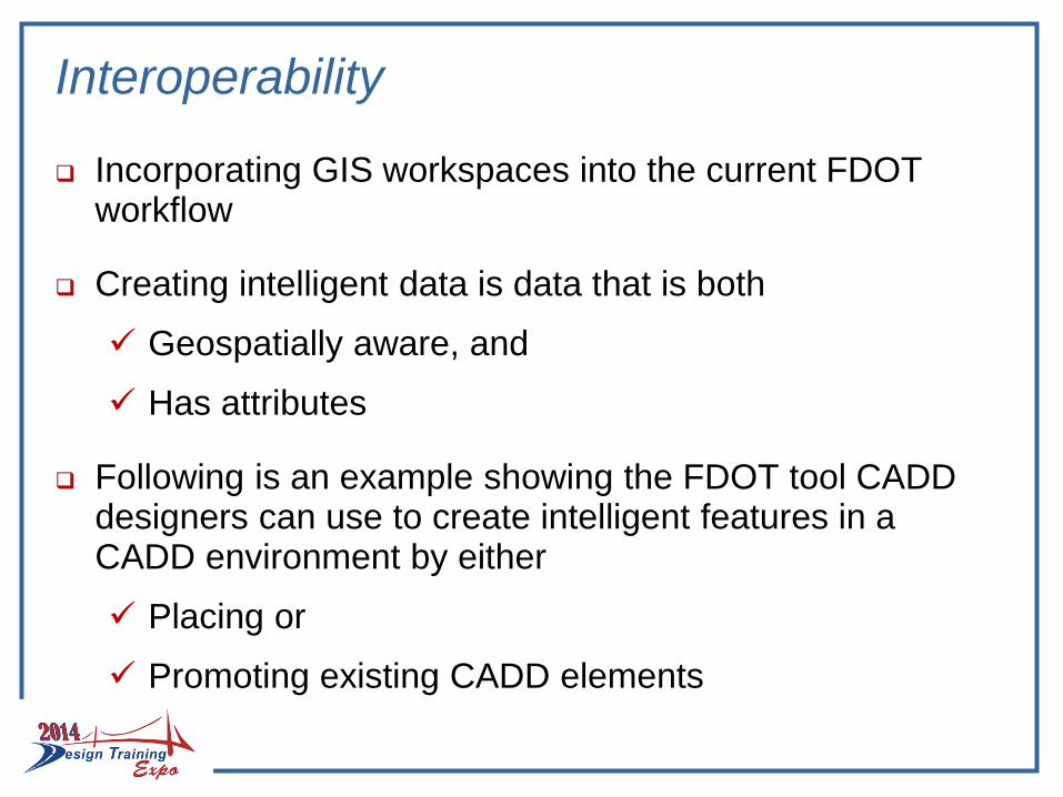
Incorporating GIS workspaces into the current FDOT workflow
Creating intelligent data is data that is both
Geospatially aware, and
Has attributes
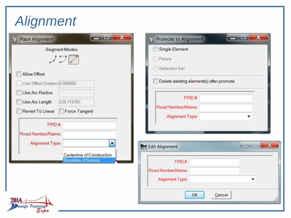
Following is an example showing the FDOT tool CADD designers can use to create intelligent features in a CADD environment by either
Placing or
Promoting existing CADD elements
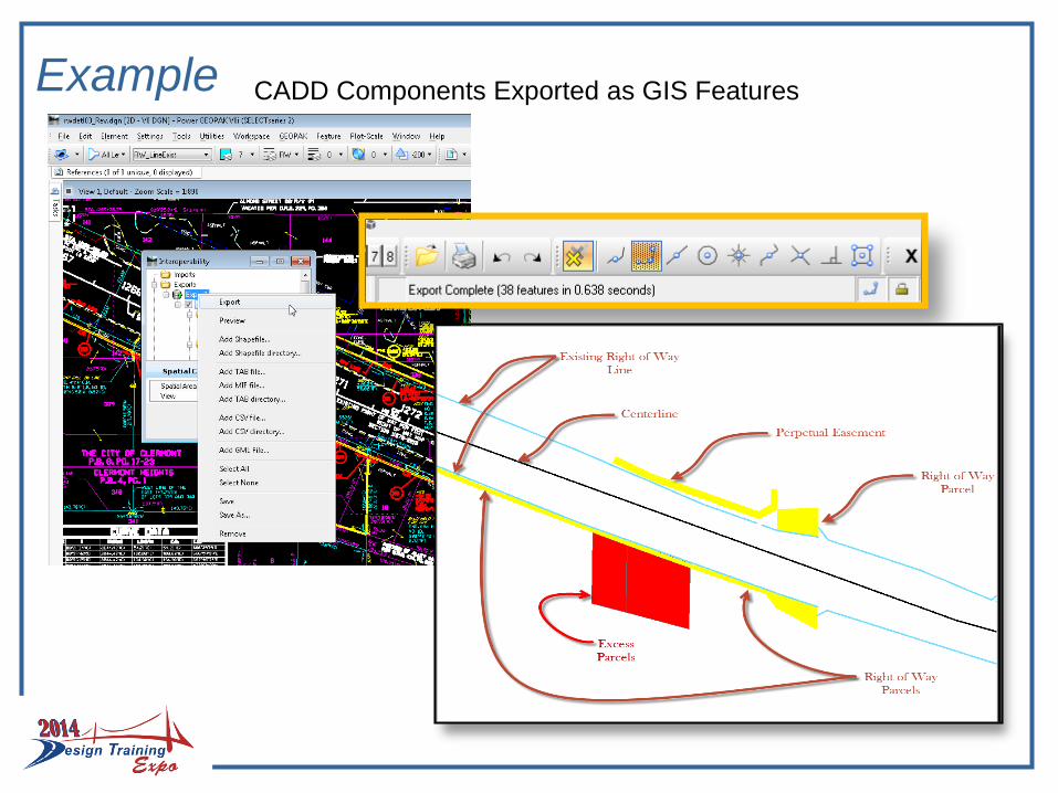
Example CADD Components Exported as GIS Features
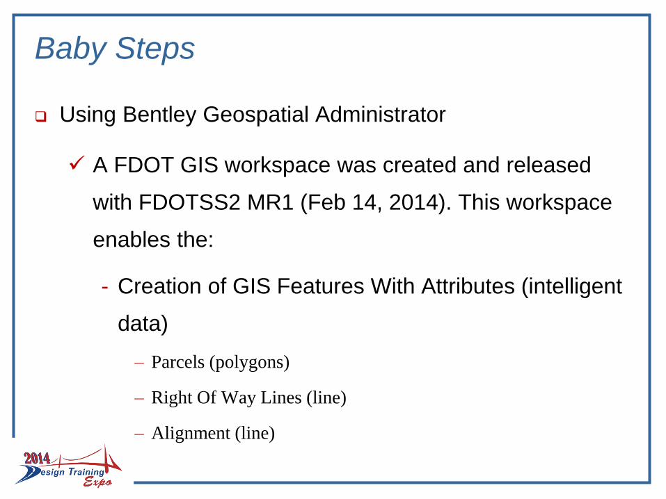
Baby Steps
Using Bentley Geospatial Administrator
A FDOT GIS workspace was created and released
with FDOTSS2 MR1 (Feb 14, 2014). This workspace
enables the:
- Creation of GIS Features With Attributes (intelligent
data)
– Parcels (polygons)
– Right Of Way Lines (line)
– Alignment (line)
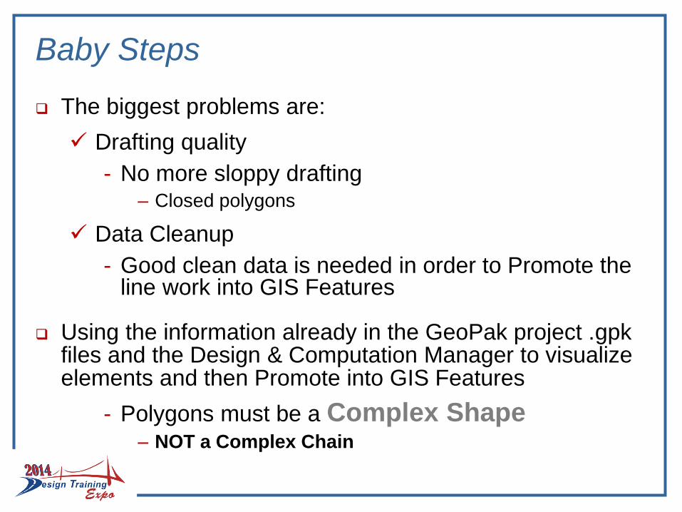
Baby Steps
The biggest problems are:
Drafting quality
- No more sloppy drafting– Closed polygons
Data Cleanup
- Good clean data is needed in order to Promote the line work into GIS Features
Using the information already in the GeoPak project .gpk files and the Design & Computation Manager to visualize elements and then Promote into GIS Features
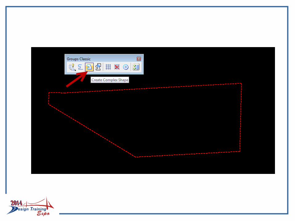
- Polygons must be a Complex Shape– NOT a Complex Chain
DRAFTING GIS FEATURES IN MICROSTATION
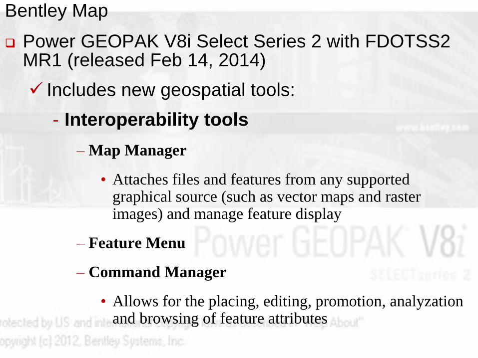
Bentley Map
Power GEOPAK V8i Select Series 2 with FDOTSS2 MR1 (released Feb 14, 2014)
Includes new geospatial tools:
- Interoperability tools
– Map Manager
• Attaches files and features from any supported graphical source (such as vector maps and raster images) and manage feature display
– Feature Menu
– Command Manager
• Allows for the placing, editing, promotion, analyzationand browsing of feature attributes
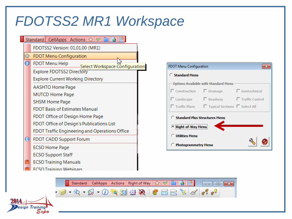
FDOTSS2 MR1 Workspace
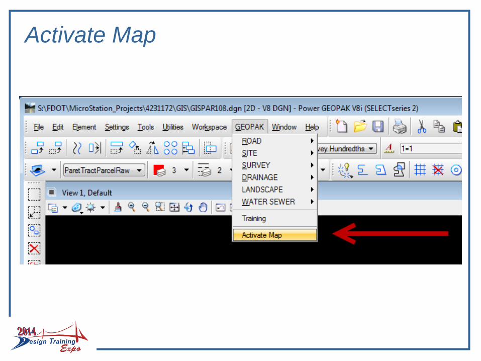
Activate Map
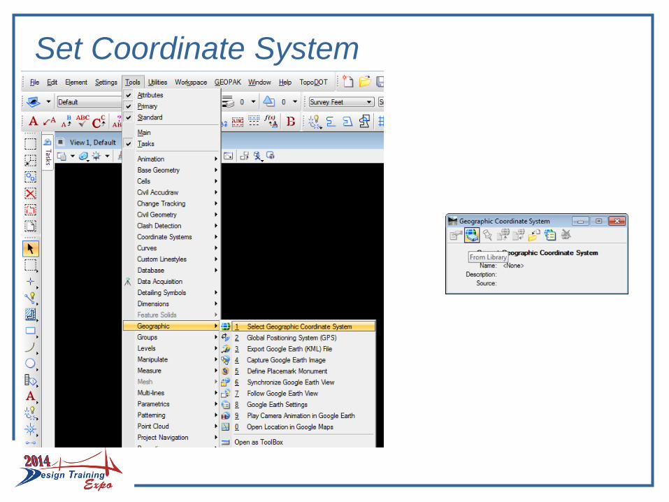
Set Coordinate System
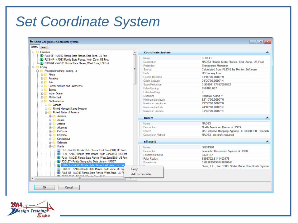
Set Coordinate System
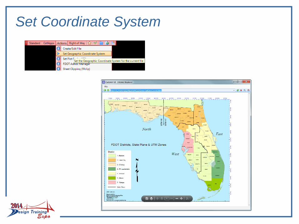
Set Coordinate System
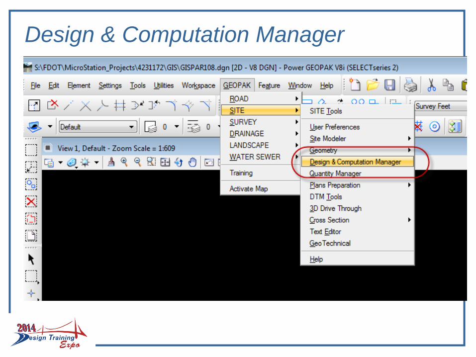
Design & Computation Manager
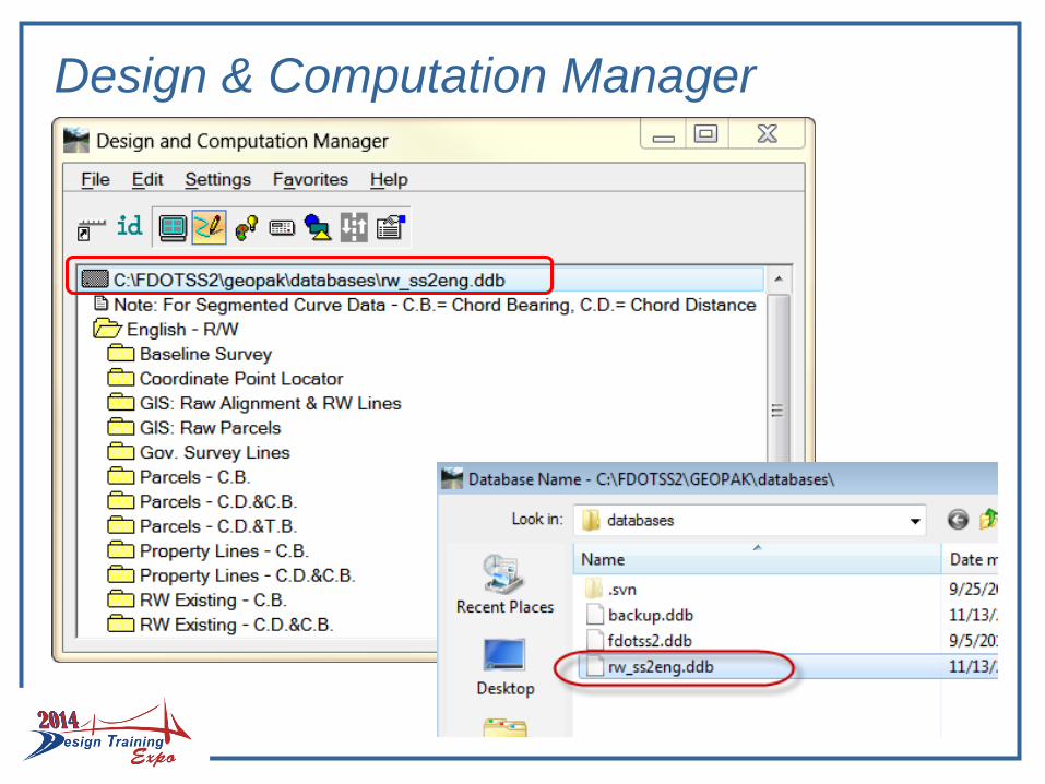
Design & Computation Manager
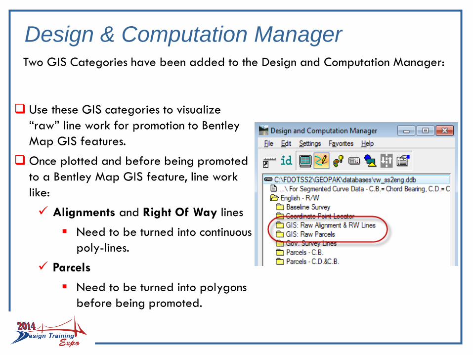
Two GIS Categories have been added to the Design and Computation Manager:
Use these GIS categories to visualize
“raw” line work for promotion to Bentley
Map GIS features.
Once plotted and before being promoted
to a Bentley Map GIS feature, line work
like:
Alignments and Right Of Way lines
Need to be turned into continuous
poly-lines.
Parcels
Need to be turned into polygons
before being promoted.
Design & Computation Manager
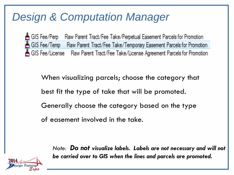
When visualizing parcels; choose the category that
best fit the type of take that will be promoted.
Generally choose the category based on the type
of easement involved in the take.
Note: Do not visualize labels. Labels are not necessary and will not
be carried over to GIS when the lines and parcels are promoted.
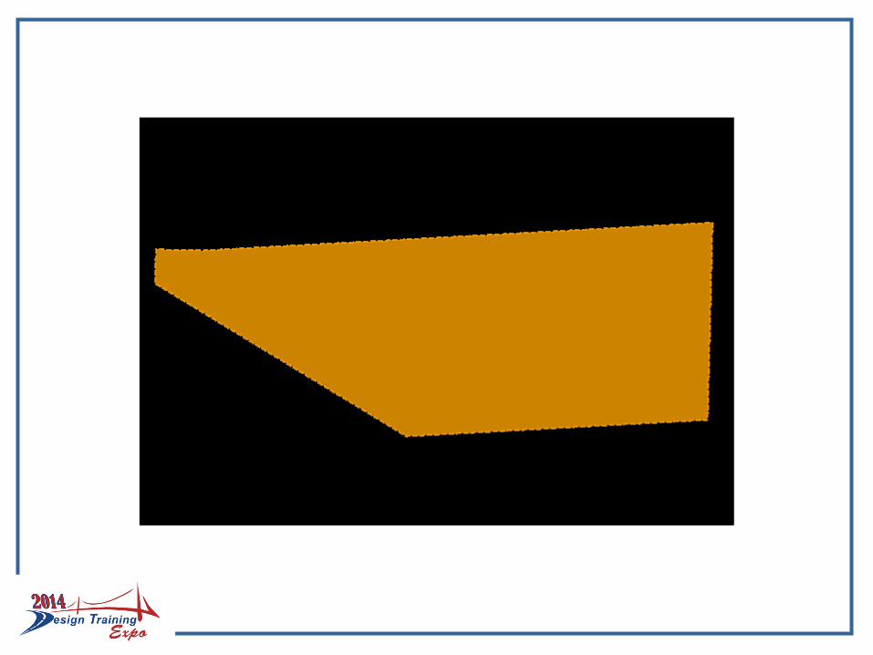
Design & Computation Manager
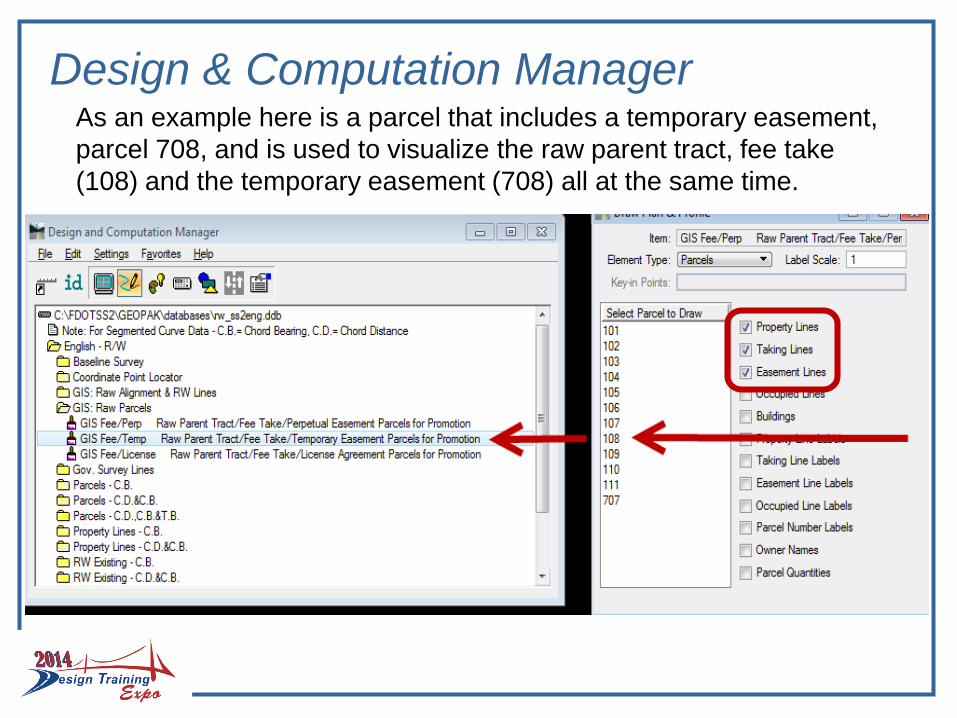
As an example here is a parcel that includes a temporary easement,
parcel 708, and is used to visualize the raw parent tract, fee take
(108) and the temporary easement (708) all at the same time.
Design & Computation Manager
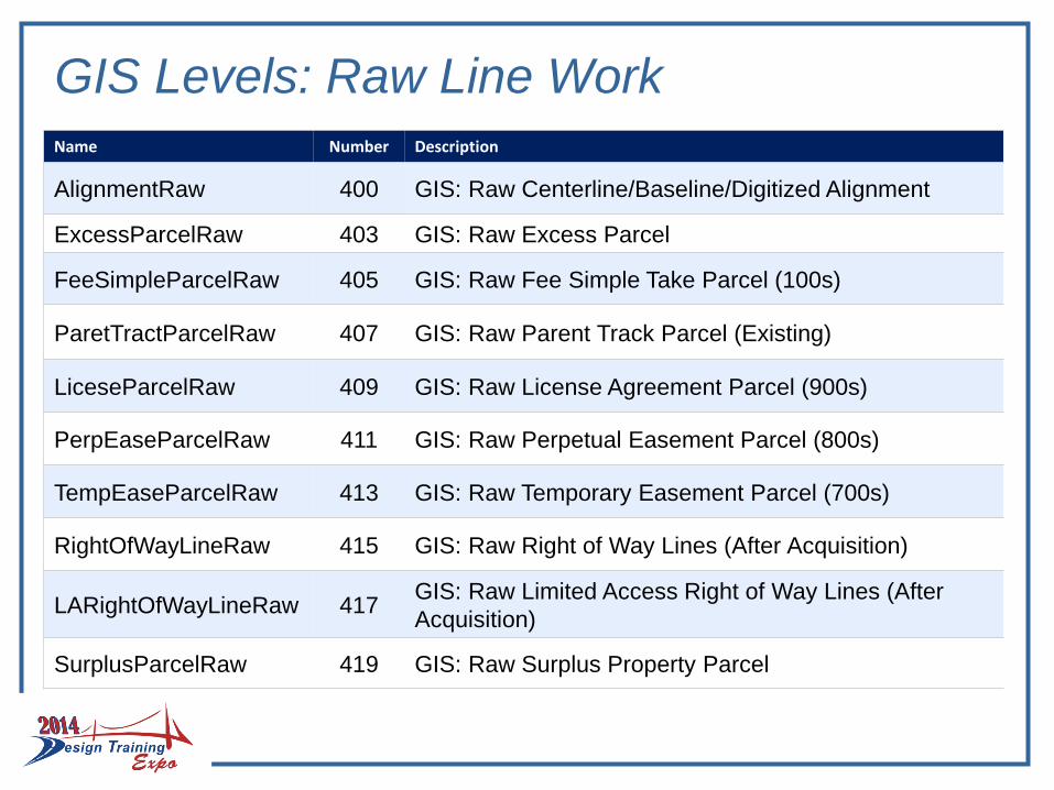
GIS Levels: Raw Line Work
Name Number Description
AlignmentRaw 400 GIS: Raw Centerline/Baseline/Digitized Alignment
ExcessParcelRaw 403 GIS: Raw Excess Parcel
FeeSimpleParcelRaw 405 GIS: Raw Fee Simple Take Parcel (100s)
ParetTractParcelRaw 407 GIS: Raw Parent Track Parcel (Existing)
LiceseParcelRaw 409 GIS: Raw License Agreement Parcel (900s)
PerpEaseParcelRaw 411 GIS: Raw Perpetual Easement Parcel (800s)
TempEaseParcelRaw 413 GIS: Raw Temporary Easement Parcel (700s)
RightOfWayLineRaw 415 GIS: Raw Right of Way Lines (After Acquisition)
LARightOfWayLineRaw 417GIS: Raw Limited Access Right of Way Lines (After
Acquisition)
SurplusParcelRaw 419 GIS: Raw Surplus Property Parcel
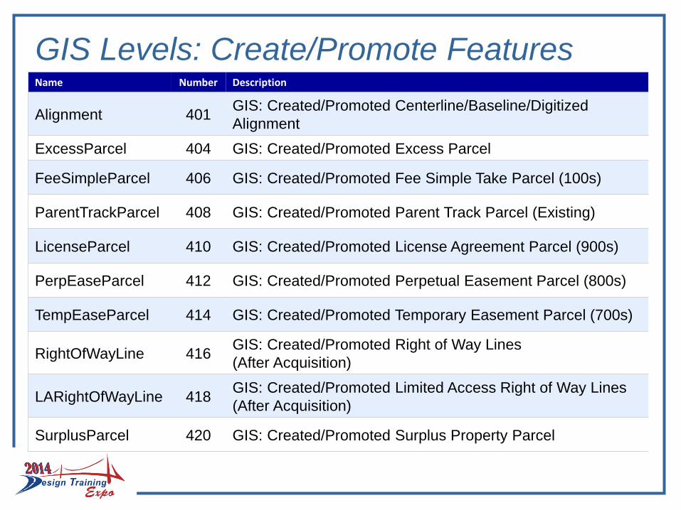
GIS Levels: Create/Promote FeaturesName Number Description
Alignment 401GIS: Created/Promoted Centerline/Baseline/Digitized
Alignment
ExcessParcel 404 GIS: Created/Promoted Excess Parcel
FeeSimpleParcel 406 GIS: Created/Promoted Fee Simple Take Parcel (100s)
ParentTrackParcel 408 GIS: Created/Promoted Parent Track Parcel (Existing)
LicenseParcel 410 GIS: Created/Promoted License Agreement Parcel (900s)
PerpEaseParcel 412 GIS: Created/Promoted Perpetual Easement Parcel (800s)
TempEaseParcel 414 GIS: Created/Promoted Temporary Easement Parcel (700s)
RightOfWayLine 416GIS: Created/Promoted Right of Way Lines
(After Acquisition)
LARightOfWayLine 418GIS: Created/Promoted Limited Access Right of Way Lines
(After Acquisition)
SurplusParcel 420 GIS: Created/Promoted Surplus Property Parcel
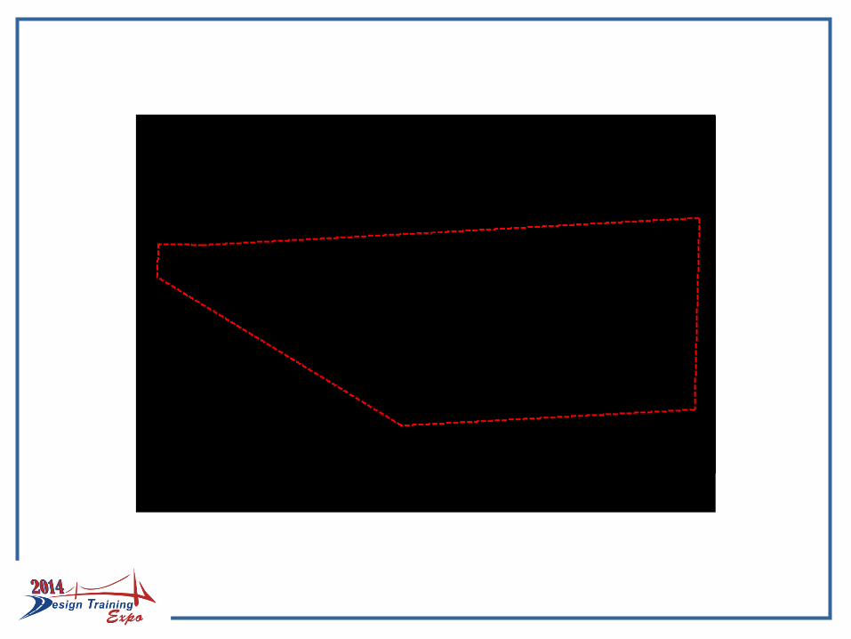
PROCESSING PARCEL LINE WORK
After the parcels are visualized from the D & C Manager, now what?
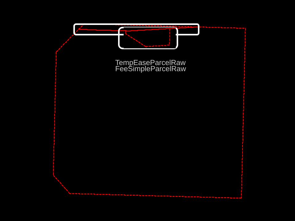
TempEaseParcelRawFeeSimpleParcelRaw
INTEROPERABILITY TOOLSCommand Manager
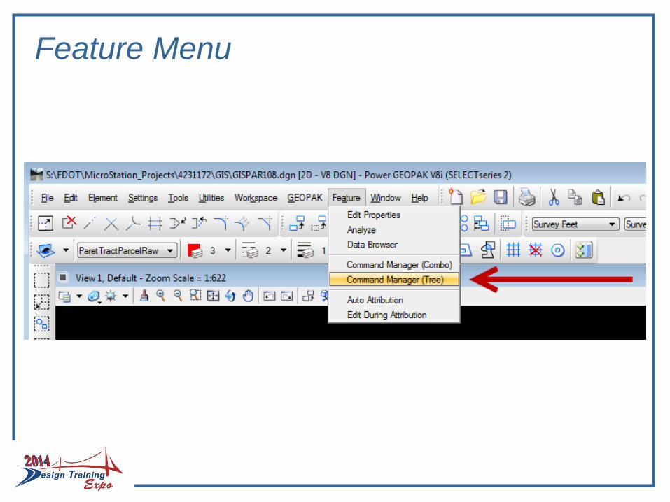
Feature Menu
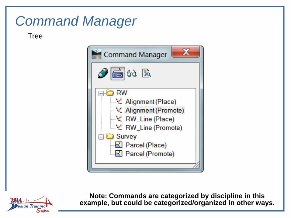
Command Manager
Note: Commands are categorized by discipline in this example, but could be categorized/organized in other ways.
Tree
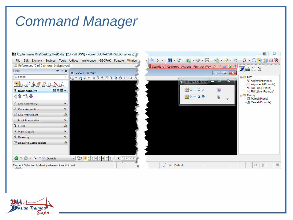
Command Manager
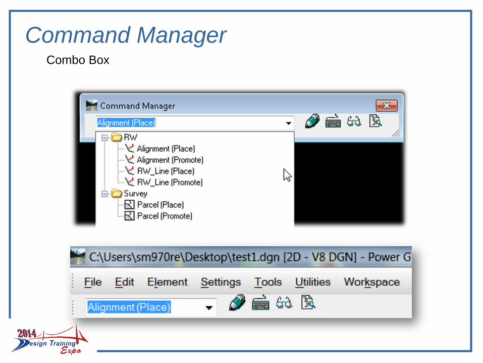
Command ManagerCombo Box
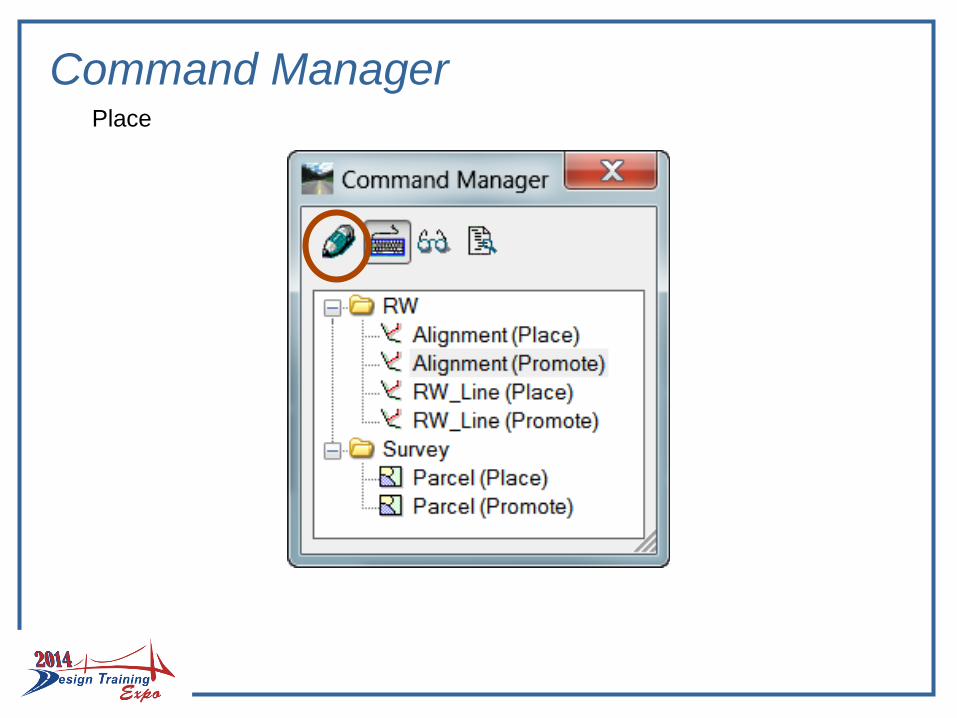
Command ManagerPlace
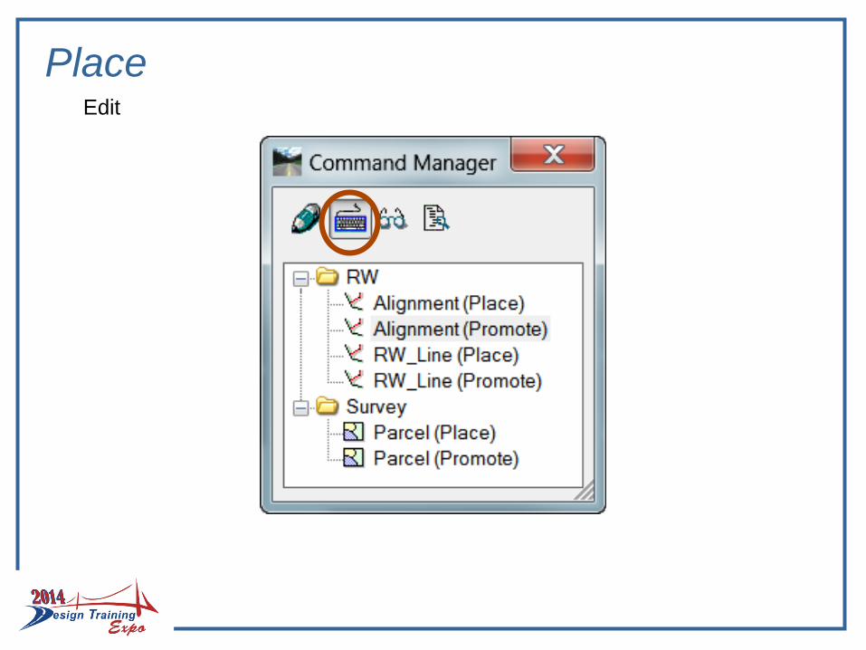
Place Edit
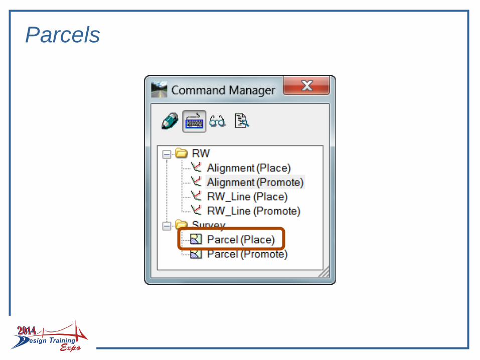
Parcels
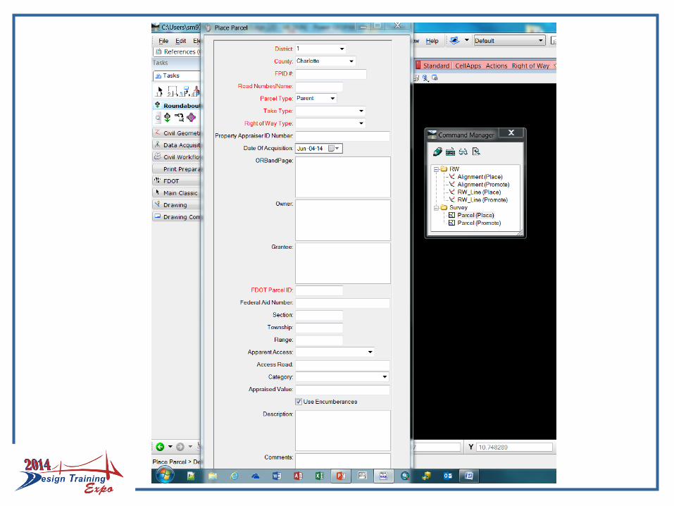
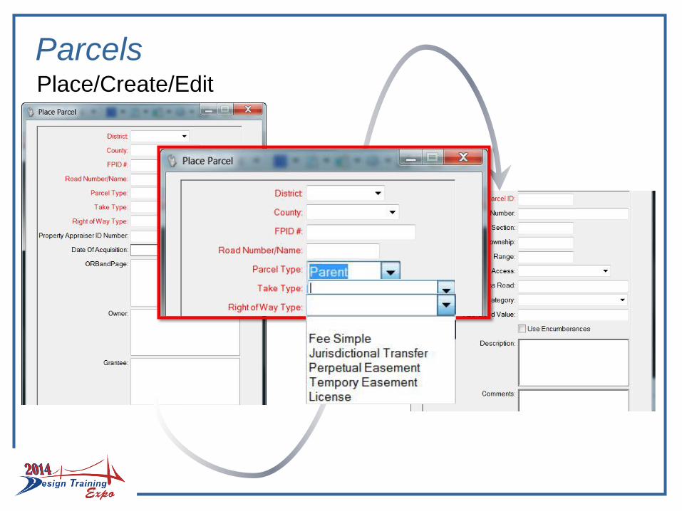
ParcelsPlace/Create/Edit
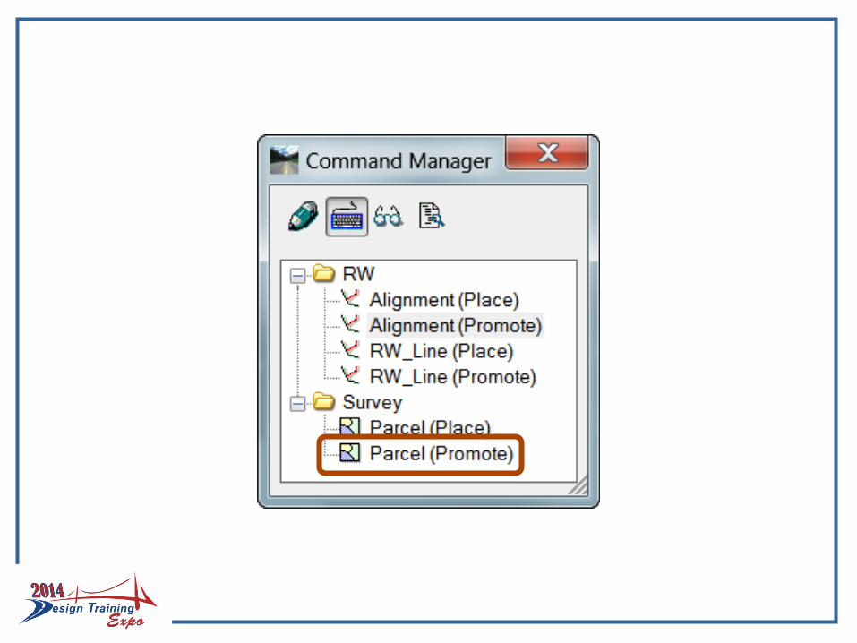
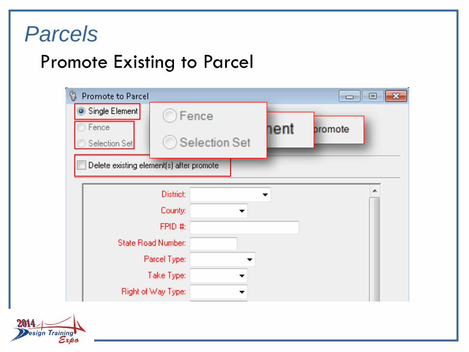
Parcels
Promote Existing to Parcel

Alignment
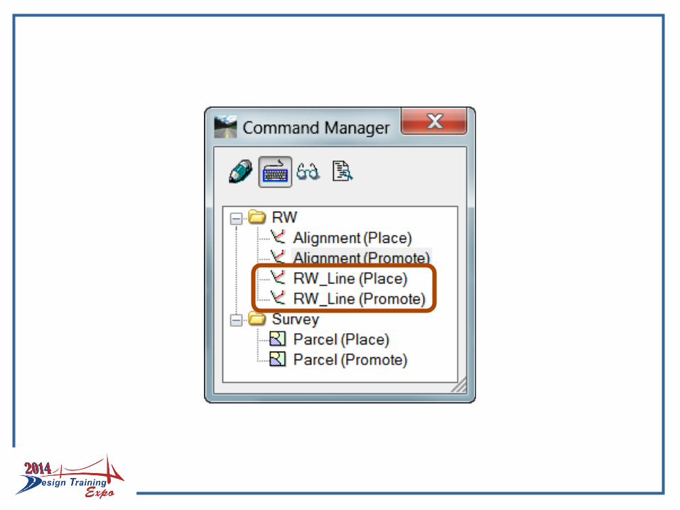
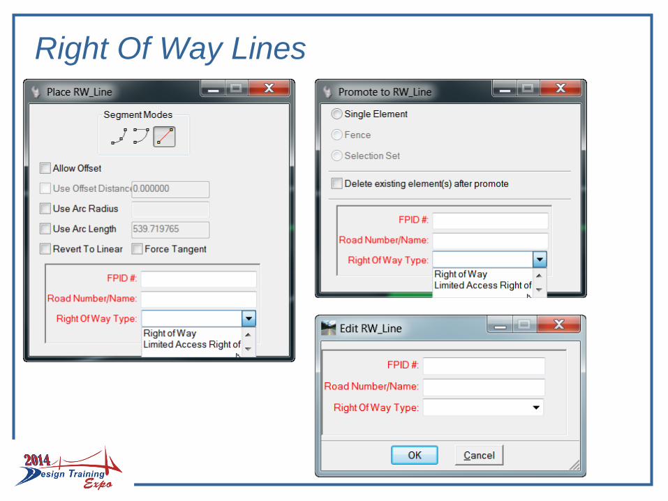
Right Of Way Lines
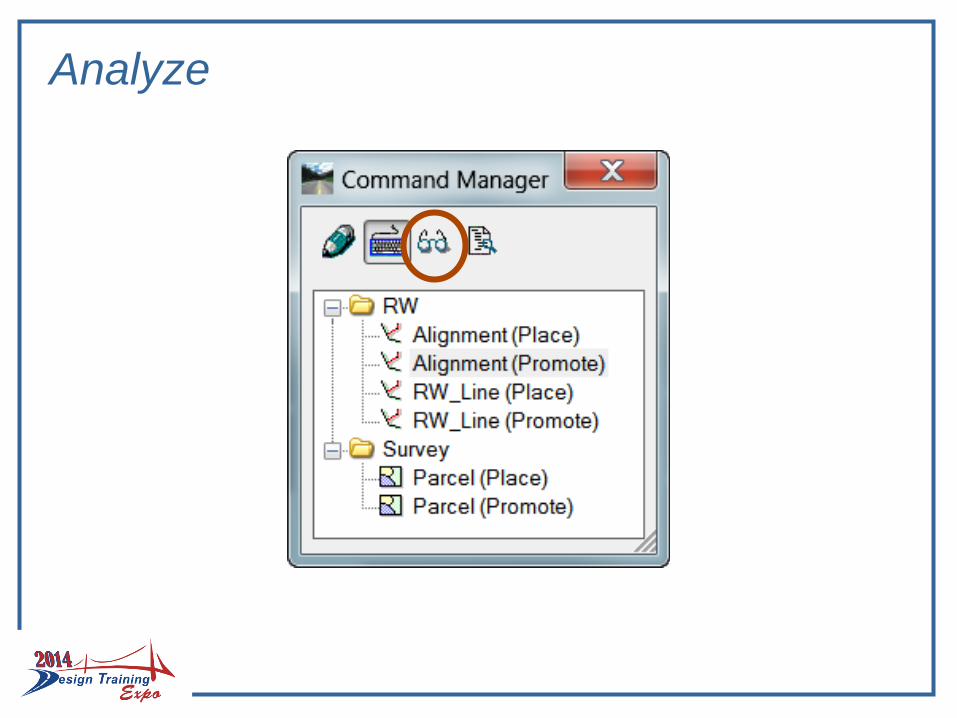
Analyze
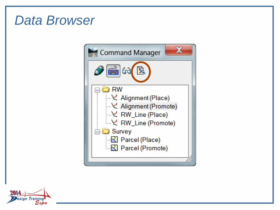
Data Browser
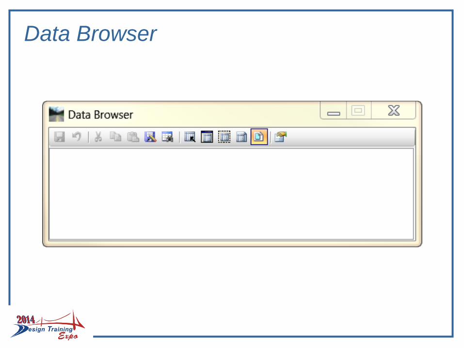
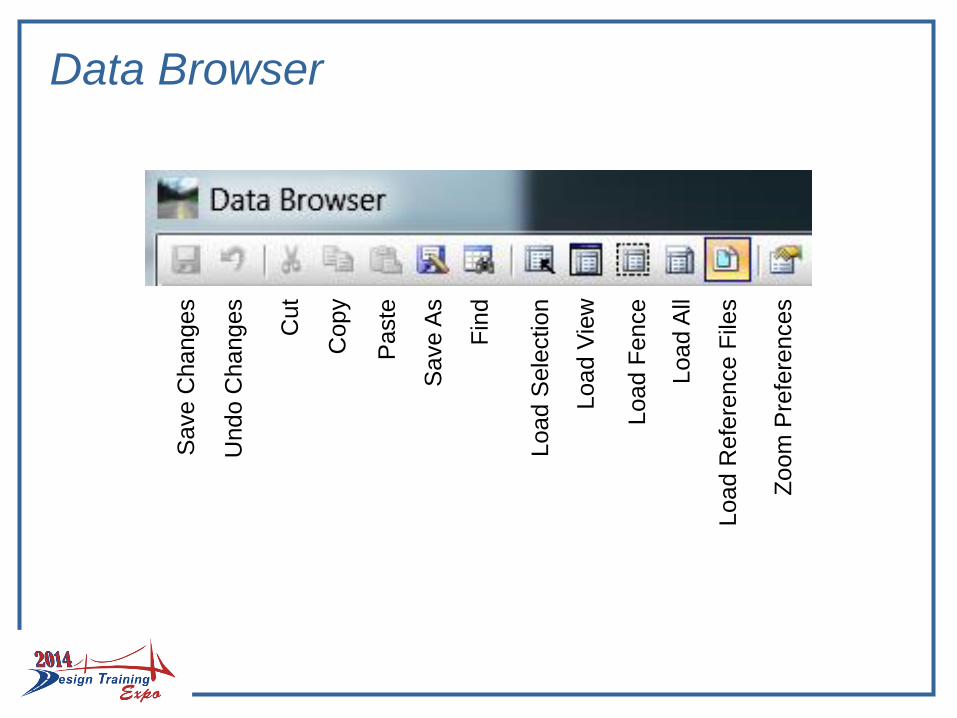
Data Browser
Data Browser
Save C
hanges
Undo C
hanges
Cut
Copy
Paste
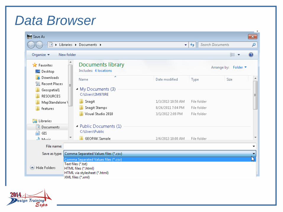
Save A
s
Fin
d
Load S
ele
ction
Load V
iew
Load F
ence
Load A
ll
Load R
efe
rence F
iles
Zo
om
Pre
fere
nces
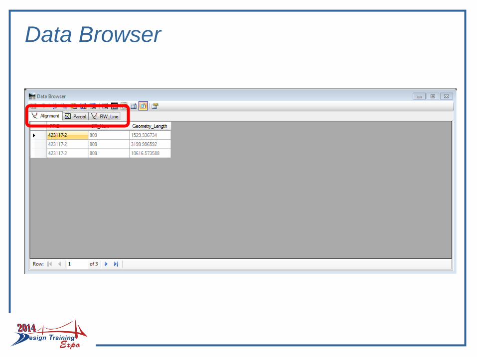
Data Browser
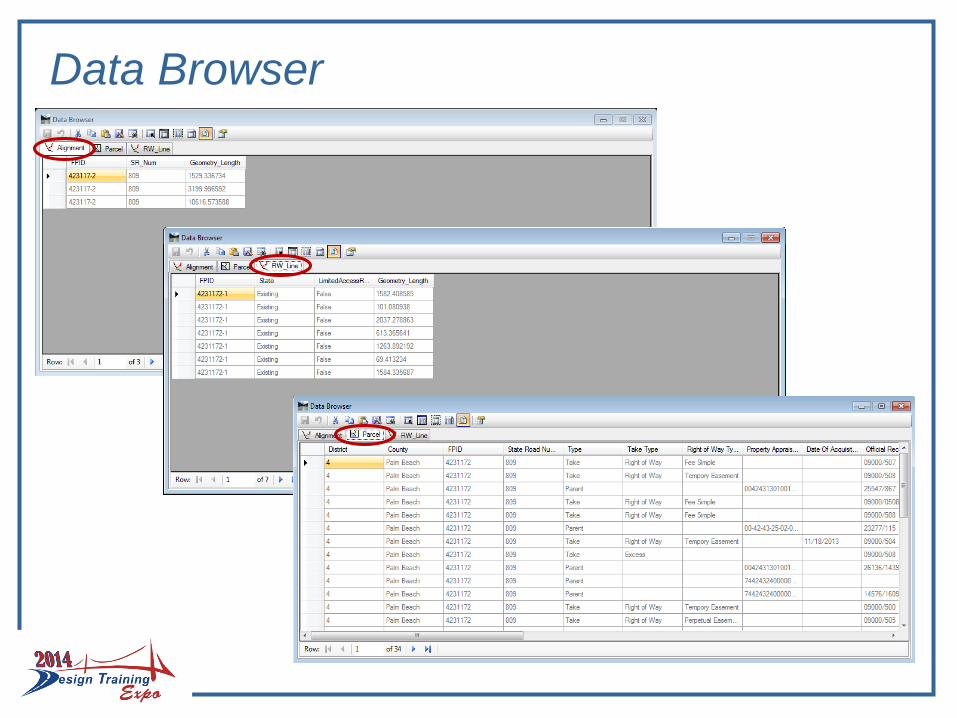
Data Browser
Data Browser
Where does this fit into my project?
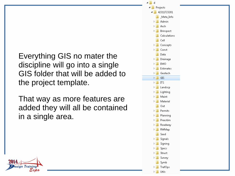
Everything GIS no mater the discipline will go into a single GIS folder that will be added to the project template.
That way as more features are added they will all be contained in a single area.
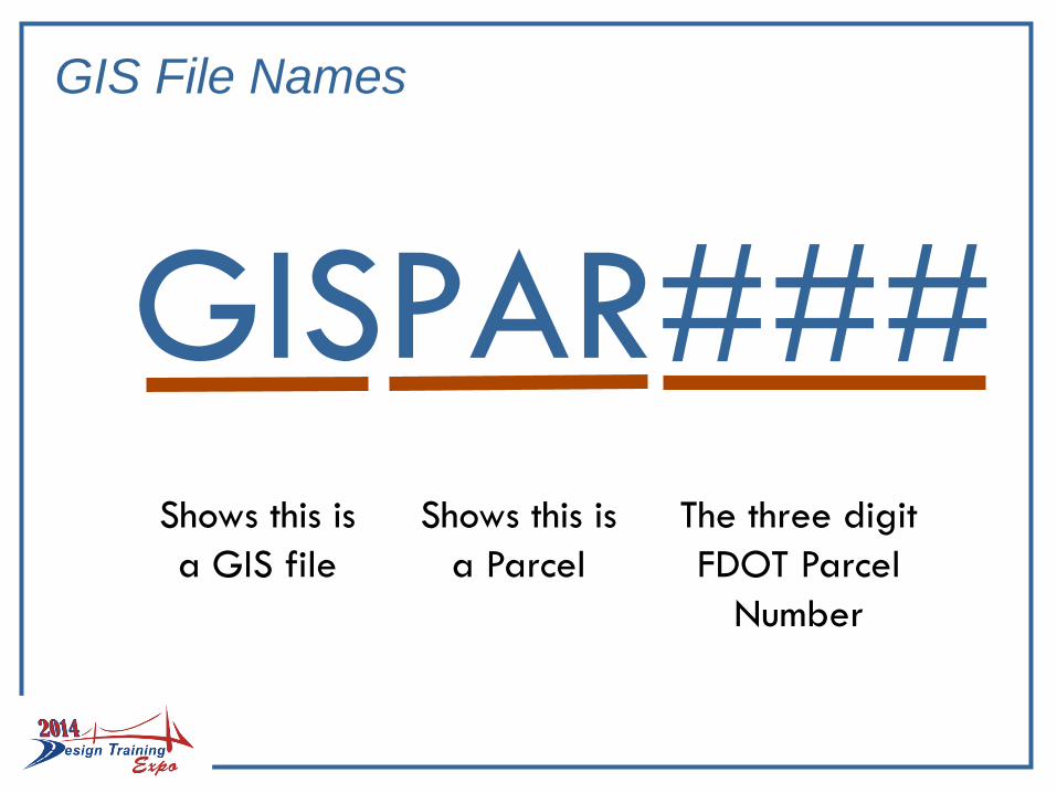
GIS File Names
GISPAR###Shows this is
a GIS file
Shows this is
a Parcel
The three digit
FDOT Parcel
Number
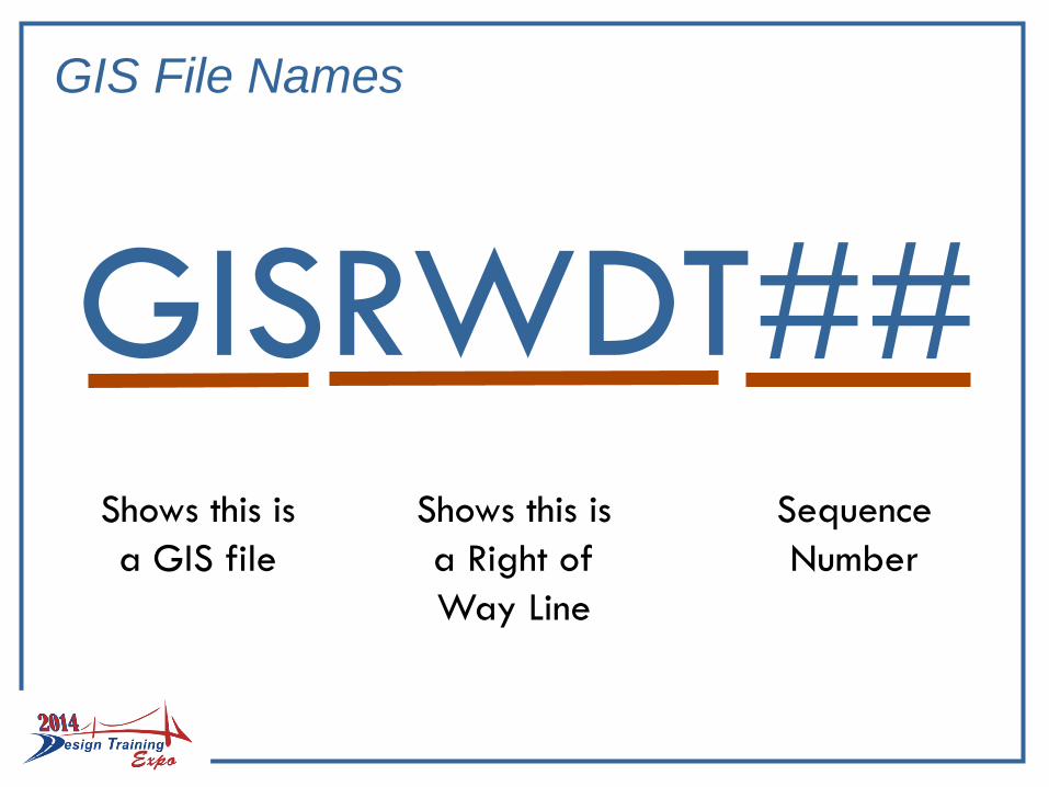
GIS File Names
GISRWDT##Shows this is
a GIS file
Shows this is
a Right of
Way Line
Sequence
Number
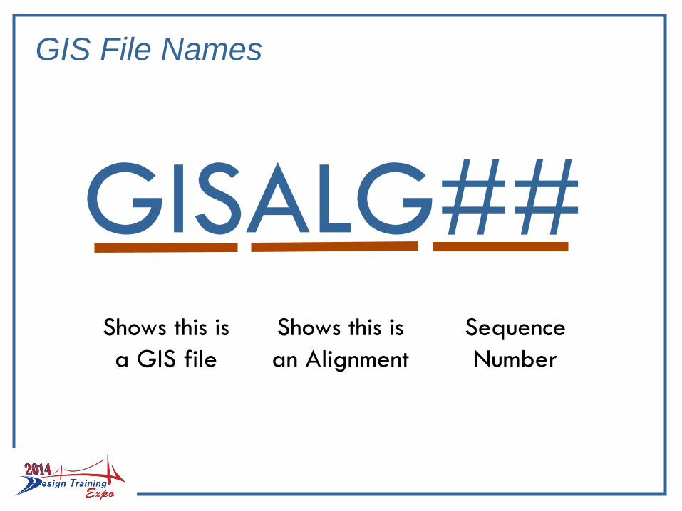
GIS File Names
Shows this is
a GIS file
Shows this is
an Alignment
Sequence
Number
GISALG##
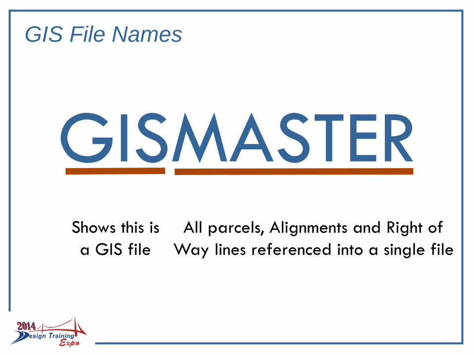
GIS File Names
Shows this is
a GIS file
All parcels, Alignments and Right of
Way lines referenced into a single file
GISMASTER
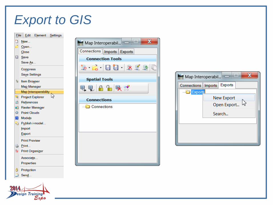
Export to GIS
Export to GIS
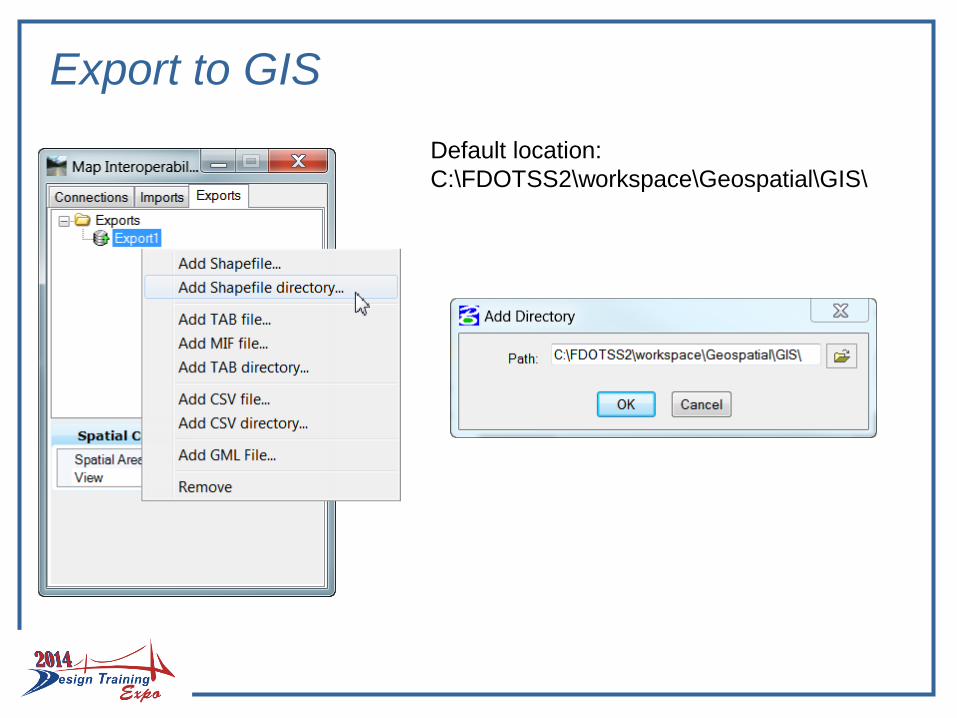
Default location:
C:\FDOTSS2\workspace\Geospatial\GIS\
Export to GIS
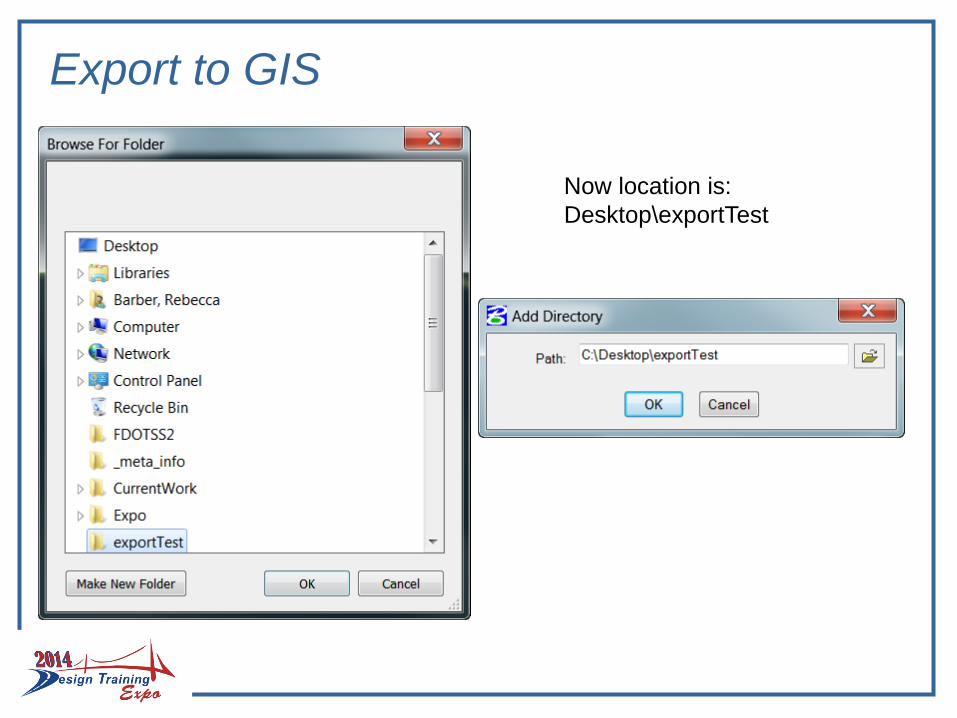
Now location is:
Desktop\exportTest
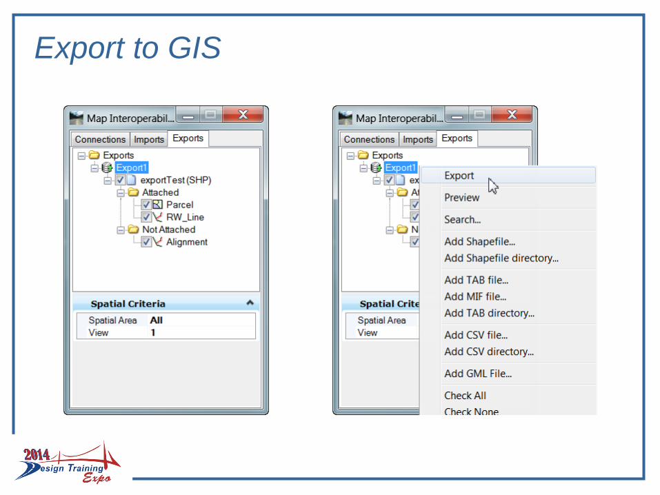
Export to GIS
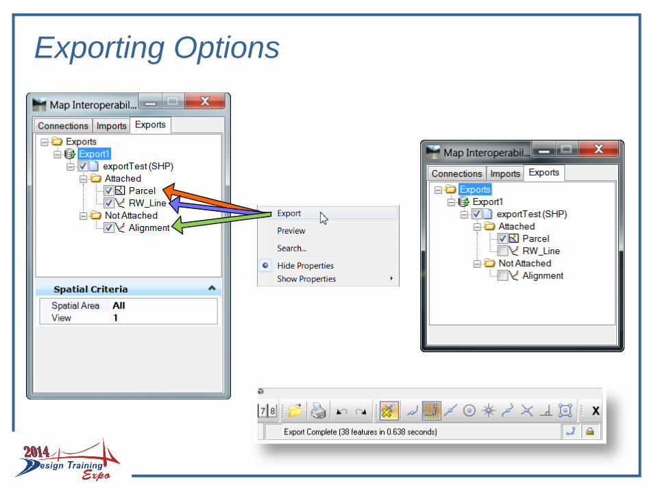
Exporting Options
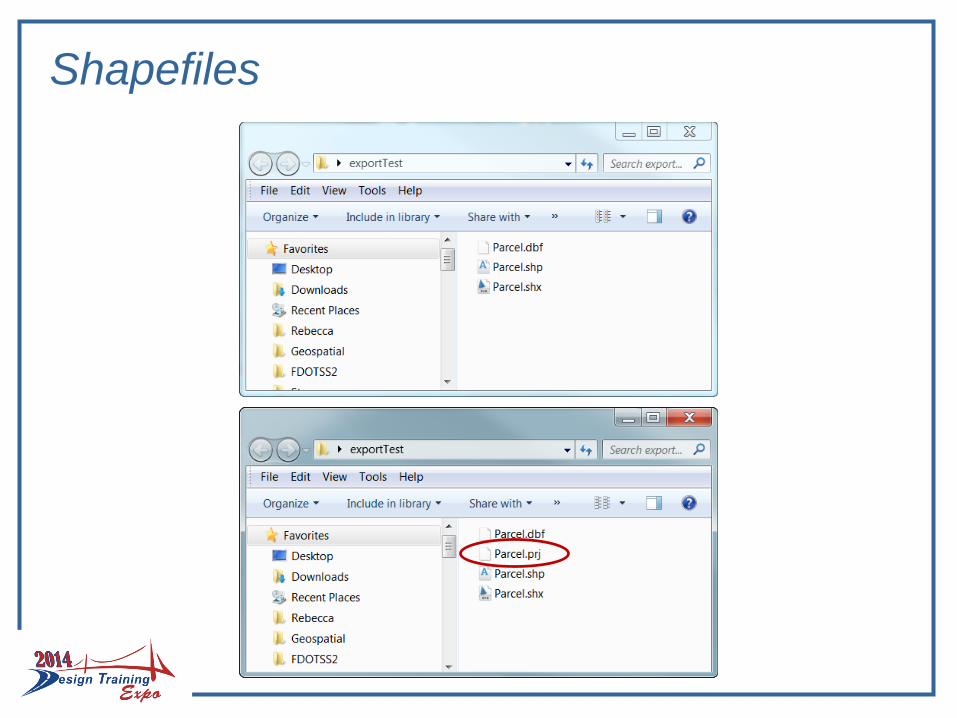
Shapefiles

BETA TESTING
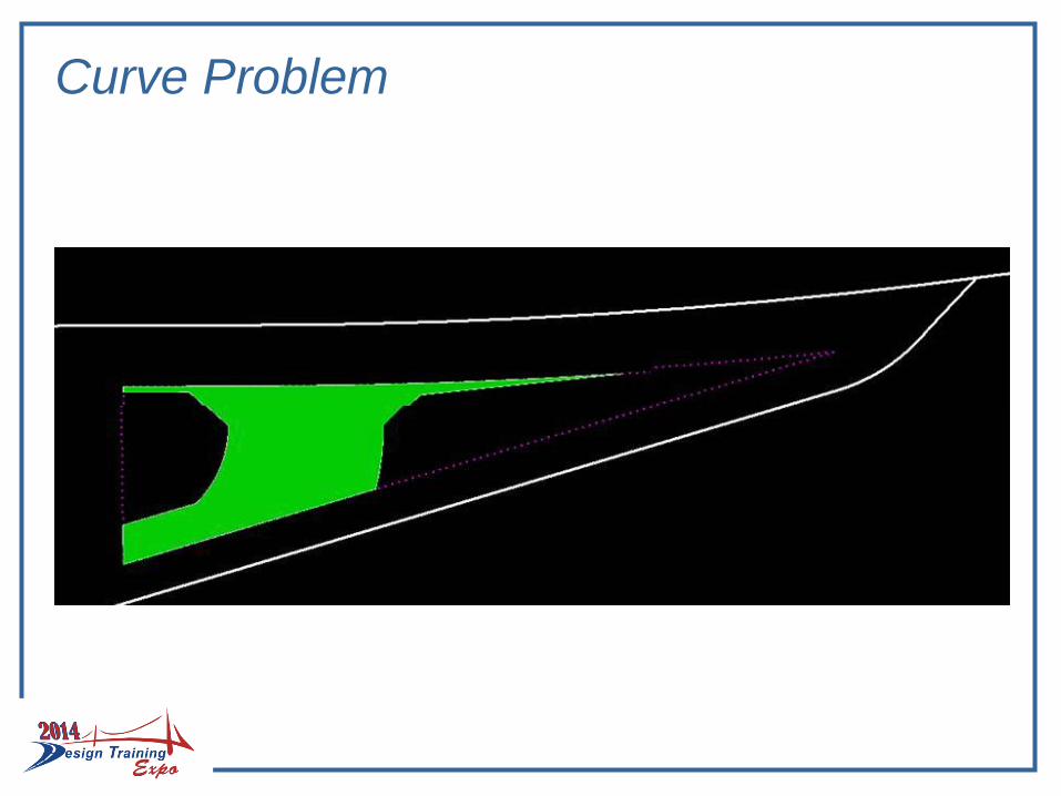
Curve Problem
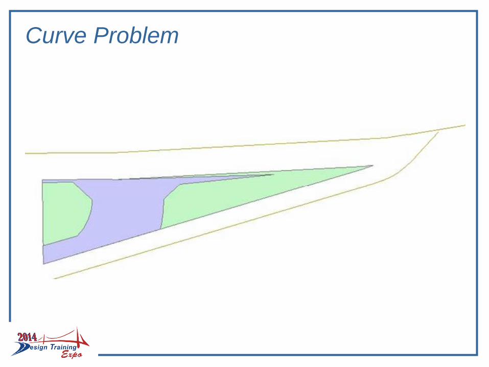
Curve Problem
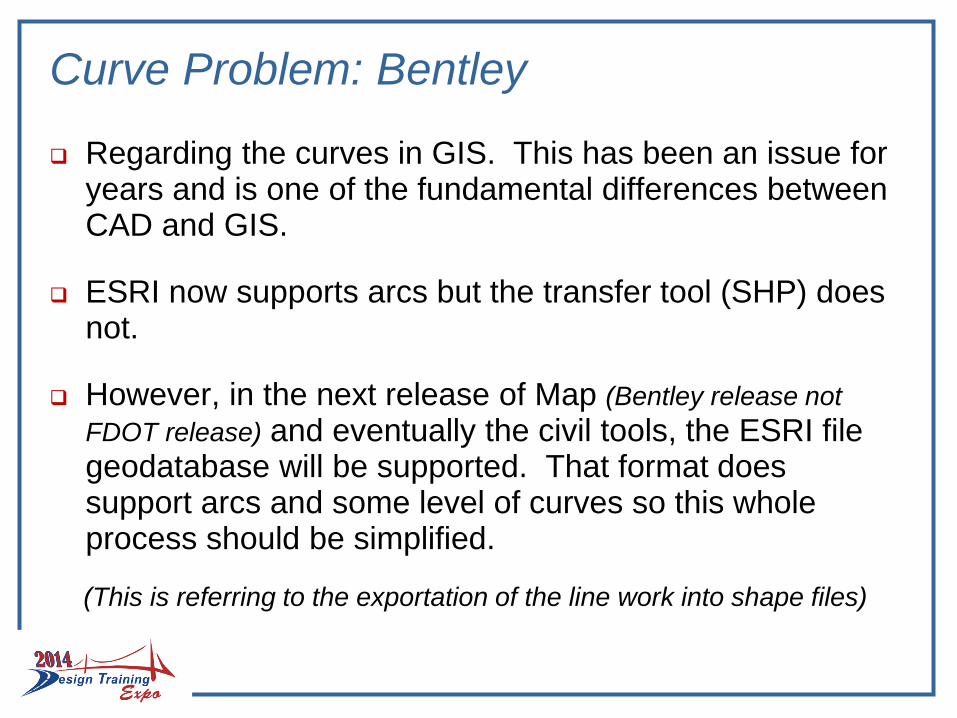
Curve Problem: Bentley
Regarding the curves in GIS. This has been an issue for years and is one of the fundamental differences between CAD and GIS.
ESRI now supports arcs but the transfer tool (SHP) does not.
However, in the next release of Map (Bentley release not
FDOT release) and eventually the civil tools, the ESRI file geodatabase will be supported. That format does support arcs and some level of curves so this whole process should be simplified.
(This is referring to the exportation of the line work into shape files)
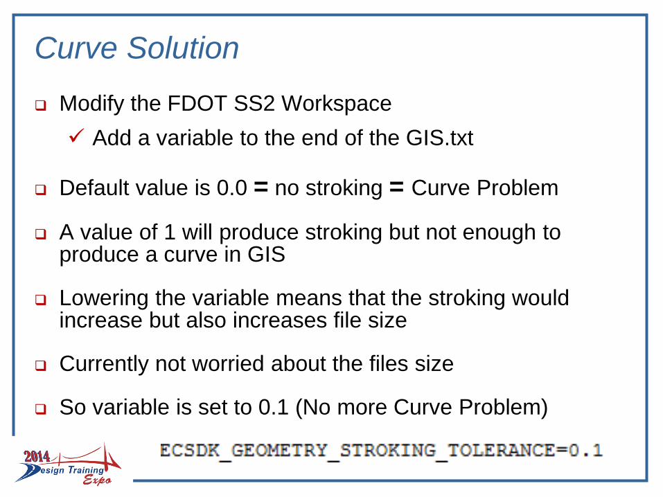
Curve Solution
Modify the FDOT SS2 Workspace
Add a variable to the end of the GIS.txt
Default value is 0.0 = no stroking = Curve Problem
A value of 1 will produce stroking but not enough to produce a curve in GIS
Lowering the variable means that the stroking would increase but also increases file size
Currently not worried about the files size
So variable is set to 0.1 (No more Curve Problem)
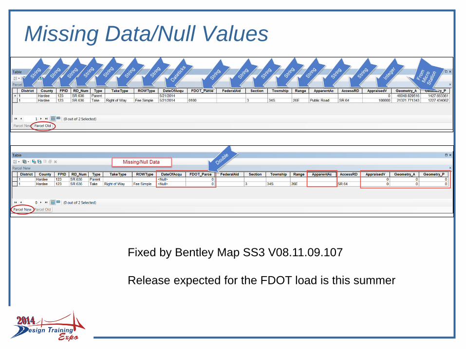
Missing Data/Null Values
Fixed by Bentley Map SS3 V08.11.09.107
Release expected for the FDOT load is this summer
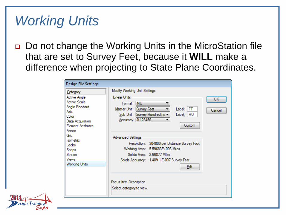
Working Units
Do not change the Working Units in the MicroStation file that are set to Survey Feet, because it WILL make a difference when projecting to State Plane Coordinates.
Summary
Process/Workflow
Develop a process/workflow allowing both CADD and GIS environments to interchange/share data
This information could become:
A one stop shop for public records requests, and
Allow for better collaborative decision making tools with stakeholders,
- whether through technical (data only in the form of tables or queries) or having a GIS/Thematic look (for display)
Summary
Enhanced querying activities to quickly support FDOT’s consultants, partners, and customers
Knowing what is located within the ROW by going to ONEplace, with links to:
maps,
aerials,
documents and
metadata
Resulting in cost savings in the areas of:
record management,
staff hours, and
informed decision making

Questions:
Contact:
Florida Department of Transportation
Surveying and Mapping Office
Tallahassee, FL
Rebecca Barber
Geographic Mapping Specialist
(850) 414-4389
Copy of presentation at:
http://www.dot.state.fl.us/officeofdesign/innovation/