Embed Size (px)
Citation preview

Add: No.33,Daxueyuan Rd.,Donghu Development Zone,Wuhan,China Zip: 430223 Tel:+86 27 81996178 Fax:+86 27 81996191 http://www.wisdri.com E-mail:[email protected]
NON-COPY, WITHOUT PERMISSION
Feasibility Study
for
Cold Rolling Project in Eastern Cape, South Africa
of
Tailong Mechanical Engineering Group Co., Ltd.
Oct. 2015
Tailong Mechanical Engineering Group Co., Ltd. Feasibility Study for Cold Rolling Project in Eastern Cape, S. Africa
Copyright © WISDRI 2015 I
Table of contents 1. Generals ...................................................................................................................... 1
1.1 Overview . . . . . . . . . . . . . . . . . . . . . . . . . . . . . . . . . . . . . . . . . . . . . . . . . . . . . . . . . . . . . . . . . . . . . . . . . . . . 1
1.2 Construction principle and guiding phi losophy of the project . . 1
1.3 Scope and content of project construction . . . . . . . . . . . . . . . . . . . . . . . . . . . . 1
1.4 Production scale and product . . . . . . . . . . . . . . . . . . . . . . . . . . . . . . . . . . . . . . . . . . . . . . 2
1.5 Incoming material and balance of metal . . . . . . . . . . . . . . . . . . . . . . . . . . . . . . . . 2
1.6 Main l ine conf iguration . . . . . . . . . . . . . . . . . . . . . . . . . . . . . . . . . . . . . . . . . . . . . . . . . . . . . . . . 4
1.7 Main uti l i ty faci l i t ies . . . . . . . . . . . . . . . . . . . . . . . . . . . . . . . . . . . . . . . . . . . . . . . . . . . . . . . . . . . . 4
1.8 General plan layout . . . . . . . . . . . . . . . . . . . . . . . . . . . . . . . . . . . . . . . . . . . . . . . . . . . . . . . . . . . . 6
1.9 Construction schedule of the project . . . . . . . . . . . . . . . . . . . . . . . . . . . . . . . . . . . . 6
1.10 Investment estimate . . . . . . . . . . . . . . . . . . . . . . . . . . . . . . . . . . . . . . . . . . . . . . . . . . . . . . . . . . . . 6
2. Market analysis ........................................................................................................... 7
3 Rolling process and equipment ................................................................................. 8
3.1 Production scale and product mix . . . . . . . . . . . . . . . . . . . . . . . . . . . . . . . . . . . . . . . . 8
3.2 Incoming material and metal balance . . . . . . . . . . . . . . . . . . . . . . . . . . . . . . . . . . . 9
3.3 Main l ine conf iguration and production process f low . . . . . . . . . . . . 10
3.4 Shop working system and annual working hours . . . . . . . . . . . . . . . . . . 12
3.5 Shop plan layout and l i f t ing & transportation equipment . . . . . . 12
3.6 Main techno-economic indices of shop . . . . . . . . . . . . . . . . . . . . . . . . . . . . . . . 13
3.7 Main equipment and production capacity of various l ines . . . . . 14
4 Power supply and electrical control ........................................................................ 22
4.1 Overview . . . . . . . . . . . . . . . . . . . . . . . . . . . . . . . . . . . . . . . . . . . . . . . . . . . . . . . . . . . . . . . . . . . . . . . . . . 22
4.2 Power supply . . . . . . . . . . . . . . . . . . . . . . . . . . . . . . . . . . . . . . . . . . . . . . . . . . . . . . . . . . . . . . . . . . . . 22
4.3 Power supply & distr ibution solution and faci l i t ies . . . . . . . . . . . . . . . 22
4.4 LV power supply & distr ibution system . . . . . . . . . . . . . . . . . . . . . . . . . . . . . . . . 23
4.5 Electrical drive and control of l ine . . . . . . . . . . . . . . . . . . . . . . . . . . . . . . . . . . . . . . 24
4.6 Electrical room and pulpi t . . . . . . . . . . . . . . . . . . . . . . . . . . . . . . . . . . . . . . . . . . . . . . . . . . 27
4.7 Lighting and movable faci l i t ies of the main bui lding . . . . . . . . . . . . . 27
Tailong Mechanical Engineering Group Co., Ltd. Feasibility Study for Cold Rolling Project in Eastern Cape, S. Africa
Copyright © WISDRI 2015 II
4.8 Crane of the main bui lding . . . . . . . . . . . . . . . . . . . . . . . . . . . . . . . . . . . . . . . . . . . . . . . . 27
4.9 Uti l i ty faci l i t ies . . . . . . . . . . . . . . . . . . . . . . . . . . . . . . . . . . . . . . . . . . . . . . . . . . . . . . . . . . . . . . . . . 27
4.10 Cabl ing and f i re f ighting . . . . . . . . . . . . . . . . . . . . . . . . . . . . . . . . . . . . . . . . . . . . . . . . . . . . 28
4.11 Lightning protection and earthing . . . . . . . . . . . . . . . . . . . . . . . . . . . . . . . . . . . . . . . 28
5 Utility facilities ............................................................................................................. 29
5.1 Overview . . . . . . . . . . . . . . . . . . . . . . . . . . . . . . . . . . . . . . . . . . . . . . . . . . . . . . . . . . . . . . . . . . . . . . . . . . 29
5.2 Water supply & drainage faci l i t ies . . . . . . . . . . . . . . . . . . . . . . . . . . . . . . . . . . . . . . 29
5.3 Thermal power faci l i t ies . . . . . . . . . . . . . . . . . . . . . . . . . . . . . . . . . . . . . . . . . . . . . . . . . . . . 35
5.4 Fuel gas faci l i t ies . . . . . . . . . . . . . . . . . . . . . . . . . . . . . . . . . . . . . . . . . . . . . . . . . . . . . . . . . . . . . 38
5.5 Description of other uti l i ty faci l i t ies . . . . . . . . . . . . . . . . . . . . . . . . . . . . . . . . . . . . 39
6 General layout & transportation .............................................................................. 40
6.1 Overview . . . . . . . . . . . . . . . . . . . . . . . . . . . . . . . . . . . . . . . . . . . . . . . . . . . . . . . . . . . . . . . . . . . . . . . . . . 40
6.2 General plan layout . . . . . . . . . . . . . . . . . . . . . . . . . . . . . . . . . . . . . . . . . . . . . . . . . . . . . . . . . . 40
6.3 Vertical arrangement and si te drainage . . . . . . . . . . . . . . . . . . . . . . . . . . . . . . 41
6.4 Transportation . . . . . . . . . . . . . . . . . . . . . . . . . . . . . . . . . . . . . . . . . . . . . . . . . . . . . . . . . . . . . . . . . . 41
6.5 Landscaping . . . . . . . . . . . . . . . . . . . . . . . . . . . . . . . . . . . . . . . . . . . . . . . . . . . . . . . . . . . . . . . . . . . . . 41
6.6 Safety and f i re f ighting . . . . . . . . . . . . . . . . . . . . . . . . . . . . . . . . . . . . . . . . . . . . . . . . . . . . . . 41
6.7 Main techno-economic indices . . . . . . . . . . . . . . . . . . . . . . . . . . . . . . . . . . . . . . . . . . . 42
7 Investment estimate .................................................................................................. 43
7.1 Project overview . . . . . . . . . . . . . . . . . . . . . . . . . . . . . . . . . . . . . . . . . . . . . . . . . . . . . . . . . . . . . . . 43
7.2 Main l ine composit ion and auxi l iary faci l i t ies . . . . . . . . . . . . . . . . . . . . . . 43
7.3 Investment estimate . . . . . . . . . . . . . . . . . . . . . . . . . . . . . . . . . . . . . . . . . . . . . . . . . . . . . . . . . . 43
7.4 Notes . . . . . . . . . . . . . . . . . . . . . . . . . . . . . . . . . . . . . . . . . . . . . . . . . . . . . . . . . . . . . . . . . . . . . . . . . . . . . . . 43
8 Analysis and evaluation of economic benefit ........................................................ 45
8.1 Overview . . . . . . . . . . . . . . . . . . . . . . . . . . . . . . . . . . . . . . . . . . . . . . . . . . . . . . . . . . . . . . . . . . . . . . . . . . . . . . 45
8.2. Captial demand and capital raising . . . . . . . . . . . . . . . . . . . . . . . . . . . . . . . . . . . . . . . . 45
8.2.1 Total investment of project . . . . . . . . . . . . . . . . . . . . . . . . . . . . . . . . . . . . . . . . . . . . . . . . . . 45
8.2.2 Construction period and designed capacity scale-up Period . . 46
8.2.3 Financial calculation and analysis . . . . . . . . . . . . . . . . . . . . . . . . . . . . . . . . . . . . . . . 46
Tailong Mechanical Engineering Group Co., Ltd. Feasibility Study for Cold Rolling Project in Eastern Cape, S. Africa
Copyright © WISDRI 2015 III
8.2.3.1 Price of raw materials and products . . . . . . . . . . . . . . . . . . . . . . . . . . . . . . . . . . 46
8.2.3.2 Cost and expense . . . . . . . . . . . . . . . . . . . . . . . . . . . . . . . . . . . . . . . . . . . . . . . . . . . . . . . . . . . . 47
8.2.3.3 Revenue . . . . . . . . . . . . . . . . . . . . . . . . . . . . . . . . . . . . . . . . . . . . . . . . . . . . . . . . . . . . . . . . . . . . . . . . . 48
8.2.3.4 Business tax . . . . . . . . . . . . . . . . . . . . . . . . . . . . . . . . . . . . . . . . . . . . . . . . . . . . . . . . . . . . . . . . . . . 49
8.2.3.5 Total prof i t . . . . . . . . . . . . . . . . . . . . . . . . . . . . . . . . . . . . . . . . . . . . . . . . . . . . . . . . . . . . . . . . . . . . . . 49
8.2.3.6 Financial viabi l i ty analysis . . . . . . . . . . . . . . . . . . . . . . . . . . . . . . . . . . . . . . . . . . . . . . . 49
8.2.3.7 Financial prof i tabi l i ty analysis . . . . . . . . . . . . . . . . . . . . . . . . . . . . . . . . . . . . . . . . . . 49
8.2.3.8 Debt-paying abi l i ty analysis . . . . . . . . . . . . . . . . . . . . . . . . . . . . . . . . . . . . . . . . . . . . . 49
8.2.4 Economic benef i t analysis of project . . . . . . . . . . . . . . . . . . . . . . . . . . . . . . . . . . . . 50
Calculation sheets are attached hereinafter. . . . . . . . . . . . . . . . . . . . . . . . . . . . . . . . . . 51
Attached drawings
1 General Plan Layout
2 Process Plan Layout
Tailong Mechanical Engineering Group Co., Ltd. Feasibility Study for Cold Rolling Project in Eastern Cape, S. Africa
Copyright © WISDRI 2015 1
1. Generals 1.1 Overview Project name: Cold Rolling Project in Eastern Cape, South Africa
Project site: COEGA Industrial Development Zone (IDZ) in Eastern Cape, South
Africa
1.2 Construction principle and guiding philosophy of the project 1) This project is built mainly to improve steel deep-processing industrial
chain in the IDZ, enhance structural upgrading of the whole IDZ and
supply high-quality, qualified cold rolled & galvanized products to the
local markets.
2) Employing the state-of-the-art process and equipment in China, it aims
to embark on a new industrilization road featuring high technological
level, good economic benift, low resource consumption, less
environmental pollution and giving full play to human resource
advantage.
3) Following the cosntruction guideline “less input, more output, high
starting point, quick effect and good quality”, advanced, practical and
reliable technical equipment shall be adopted to ensure advanced
general equipment level and optimum economic benefits.
4) Compact and reasonable shop layout shall be designed to ensure
smooth process and consider future sustainable development. Full play
shall be given to overall design of the plant to combine and symplify
configuration of utility facilities for improving labor productivity.
5) Cleaner production shall be vigorously promoted strictly in accordance
with relevant national, industrial and local policies, laws and regulations
in respect of energy saving, environmental protection, fire fighting, safety,
industrial hygine and anti seismic. Actively implementing the scientific
outlook on development and giving full play to advantage of
comprehensive resource, utilization ratio of raw material, energy and
water resource shall be increased to realize recycling of resources.
1.3 Scope and content of project construction Scope of the project construction includes annual output of 200,000t cold rolled
galvanized commercial products delivered in coils. The construction content of
Tailong Mechanical Engineering Group Co., Ltd. Feasibility Study for Cold Rolling Project in Eastern Cape, S. Africa
Copyright © WISDRI 2015 2
the project consists of:
Push-pull type pickling line 1
Single-stand reversing mill 1
Continuous galvanizing line 1
The following lines to be reserved for future:
Continuous color coating line 1
Recoiling & tension levellling line 1
Corresponding power supply & distribution system, electrical control system,
water supply & drainage, power, heating, ventilation, machinery repairing, lab.,
general layout & transportation, architecture, energy and fire fighting. And the
main utility facilities include 10kV switchgear station, acid regeneration plant,
circulation water station, waste water treatment station, demi-water station and
air compressor station, etc.
1.4 Production scale and product Tailong Mechanical Engineering Group Co., Ltd. plans to invest in Eastern Cape
to build a cold rolling pant mainly for producing galvanized products with
production scale of 200,000t/a galvanized products.
Main products of the project are as follows:
Table 1-1 Product mix
No. Product name Size Variety Output
Remarks t/a %
1 Hot galvanized
products
Thickness:
0.4~2.5mm CQ 140000 70
Galvanized
products Width:
800~1250mm DQ 60000 30
Subtotal 200000 100
Total 200000 100
1.5 Incoming material and balance of metal (1)Incoming material
~219,300t hot coils are required as incoming materials, which will be purchased
from the market. Grade and size of the incoming coils are as follows:
Steel grade: hot rolled low carbon steel
Strip thickness: 2.5~5.0mm
Tailong Mechanical Engineering Group Co., Ltd. Feasibility Study for Cold Rolling Project in Eastern Cape, S. Africa
Copyright © WISDRI 2015 3
Strip width: 800~1250mm
I.D. of coil: Φ762mm
O.D. of coil: max.Φ2000mm
Coil weight: max.25t
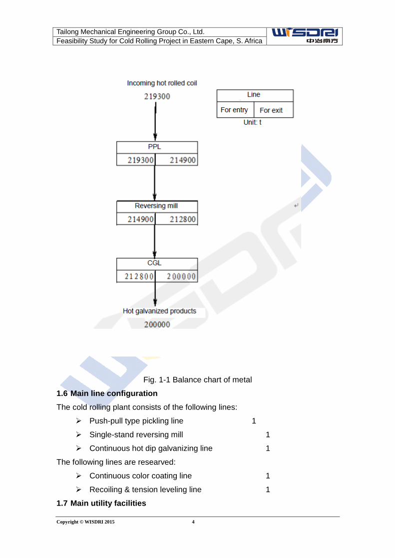
(2) Metal balance sheet and chart
Metal balance sheet of this project is as follows:
Table 1-2 Metal Balance Sheet
No. Product name
Amount of
incoming
material
Finished product
output
Crop, trimming and
loss, etc. Yield
(t/a) (t/a) (t/a) (t/a) % %
1 Galvanized
product 219300 200000 19300 8.8 91.2
See Fig. 1-1 for metal balance chart of this project.
Tailong Mechanical Engineering Group Co., Ltd. Feasibility Study for Cold Rolling Project in Eastern Cape, S. Africa
Copyright © WISDRI 2015 4
Fig. 1-1 Balance chart of metal
1.6 Main line configuration The cold rolling plant consists of the following lines:
Push-pull type pickling line 1
Single-stand reversing mill 1
Continuous hot dip galvanizing line 1
The following lines are researved:
Continuous color coating line 1
Recoiling & tension leveling line 1
1.7 Main utility facilities
Tailong Mechanical Engineering Group Co., Ltd. Feasibility Study for Cold Rolling Project in Eastern Cape, S. Africa
Copyright © WISDRI 2015 5
1.7.1 Power supply & distribution facilities One 10kV switchgear station is designed to supply power for main production
lines and relevant utility facilities. Sub-switchgear-station of lower level could be
designed as necessary. The 10kV power source required for the switchgear
station is fed from outside.
1.7.2 Water supply & drainage facility It is composed of water circulation station, waste water treatment plant, acid
regeneration station and relevant pipe network of the main building.
(1) Circulation wate station
Capacity of circulation water station:
Flow of circulation water Q=1200 m3/h, emergency water Q=30 m3/h
Feed temperature of circulation water: ≤33℃, return temperature of
circulation water ≤43℃
Feed pressure of circulation water: 0.4~0.5MPa
(2) Waste water treatment plant
Waste alkali water: 15 m3/h
Waste emulsion: 4 m3/h
(3) Acid regeneration plant
Annual amount of strip pickled: 219,000 t/a
Iron loss from pickling: 0.40%
Waste acid amount: 1300 l/h
Designed acid regeneration capacity: 2100l/h, spraying roasing method
adotped
1.7.3 Thermal power facility (1) Air compressor station
It is going to build one air compressor station, including three 50Nm3/min air
compressors with exhausting pressure 0.8MPa. Power of each compressor
motor is 280KW, and voltage is 10kV. Three 50Nm3/min combined type
compressed air dryers are also foreseen.
(2) Demi-water station
It is going to build one demi-water station with output of 25t/h. Quality of output
water reaches class 1 standard of demi-water (conductivity<5μS/cm), and
quality of the demi-water could fully meet requirements of the process lines.
Tailong Mechanical Engineering Group Co., Ltd. Feasibility Study for Cold Rolling Project in Eastern Cape, S. Africa
Copyright © WISDRI 2015 6
(3) Steam supply
Max. comprehensive steam consumption of this project is 20.3t/h, and all the
steam required are supplied from external steam source.
1.7.4 Fuel gas media Liquified petroleum gas, nitrogen and hydrogen required for the project are all
supplied via pipe from outside to the plant.
1.7.5 Other facilities The project is also designed with roll grinding facility, lab. facility and special fire
fighting facility, etc.
1.8 General plan layout Given the fact that comprehensive transportation mode is road transportation
and the project site is nearby wharf, the generally layout will be designed
following the principle that main raw material storage and finished product
storage are arranged close to entry/exit for the purpose of convenient
transportation.
The main building of the cold rolling plant is arranged nearby the south of the
battery limit. Electrical room of PL, electrical room of rolling mill (incl. 10kV
switchgear station), entry electrical room of CGL and exit electrical room of CGL
are arranged around the main building. Waste water treatment plant, circulation
water station and air compressor station are arranged one after another from
west to east across the road to the north of the main building. The
comprehensive building is arranged to the east of the main building and to the
south of the entry/exit.
1.9 Construction schedule of the project According to overall planning of the project, it is expcted to be built in 24 months
after effectiveness of the Contract, not including enquiry, negotiation and
feasibility study in the prophase period as well as hot load test and function test
time after startup.
1.10 Investment estimate The static investment of the project is $53,820,000 USD.
See the investment estimate table for details.
Tailong Mechanical Engineering Group Co., Ltd. Feasibility Study for Cold Rolling Project in Eastern Cape, S. Africa
Copyright © WISDRI 2015 7
2. Market analysis See the market analysis completed by special organization entrusted by the
Owner.
Tailong Mechanical Engineering Group Co., Ltd. Feasibility Study for Cold Rolling Project in Eastern Cape, S. Africa
Copyright © WISDRI 2015 8
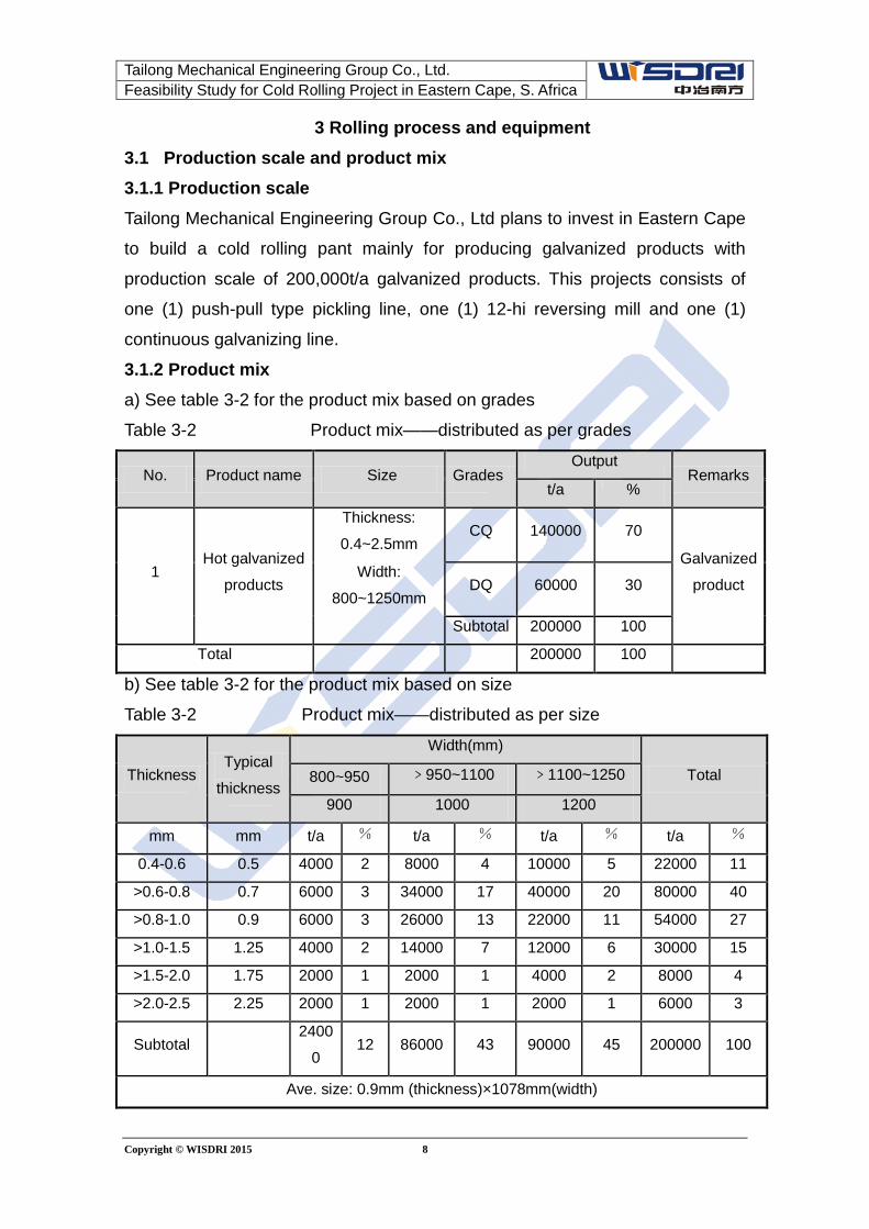
3 Rolling process and equipment 3.1 Production scale and product mix 3.1.1 Production scale Tailong Mechanical Engineering Group Co., Ltd plans to invest in Eastern Cape
to build a cold rolling pant mainly for producing galvanized products with
production scale of 200,000t/a galvanized products. This projects consists of
one (1) push-pull type pickling line, one (1) 12-hi reversing mill and one (1)
continuous galvanizing line.
3.1.2 Product mix a) See table 3-2 for the product mix based on grades
Table 3-2 Product mix——distributed as per grades
No. Product name Size Grades Output
Remarks t/a %
1 Hot galvanized
products
Thickness:
0.4~2.5mm CQ 140000 70
Galvanized
product Width:
800~1250mm DQ 60000 30
Subtotal 200000 100
Total 200000 100
b) See table 3-2 for the product mix based on size
Table 3-2 Product mix——distributed as per size
Thickness Typical
thickness
Width(mm)
Total 800~950 ﹥950~1100 ﹥1100~1250
900 1000 1200
mm mm t/a % t/a % t/a % t/a %
0.4-0.6 0.5 4000 2 8000 4 10000 5 22000 11
>0.6-0.8 0.7 6000 3 34000 17 40000 20 80000 40
>0.8-1.0 0.9 6000 3 26000 13 22000 11 54000 27
>1.0-1.5 1.25 4000 2 14000 7 12000 6 30000 15
>1.5-2.0 1.75 2000 1 2000 1 4000 2 8000 4
>2.0-2.5 2.25 2000 1 2000 1 2000 1 6000 3
Subtotal
2400
0 12 86000 43 90000 45 200000 100
Ave. size: 0.9mm (thickness)×1078mm(width)
Tailong Mechanical Engineering Group Co., Ltd. Feasibility Study for Cold Rolling Project in Eastern Cape, S. Africa
Copyright © WISDRI 2015 9
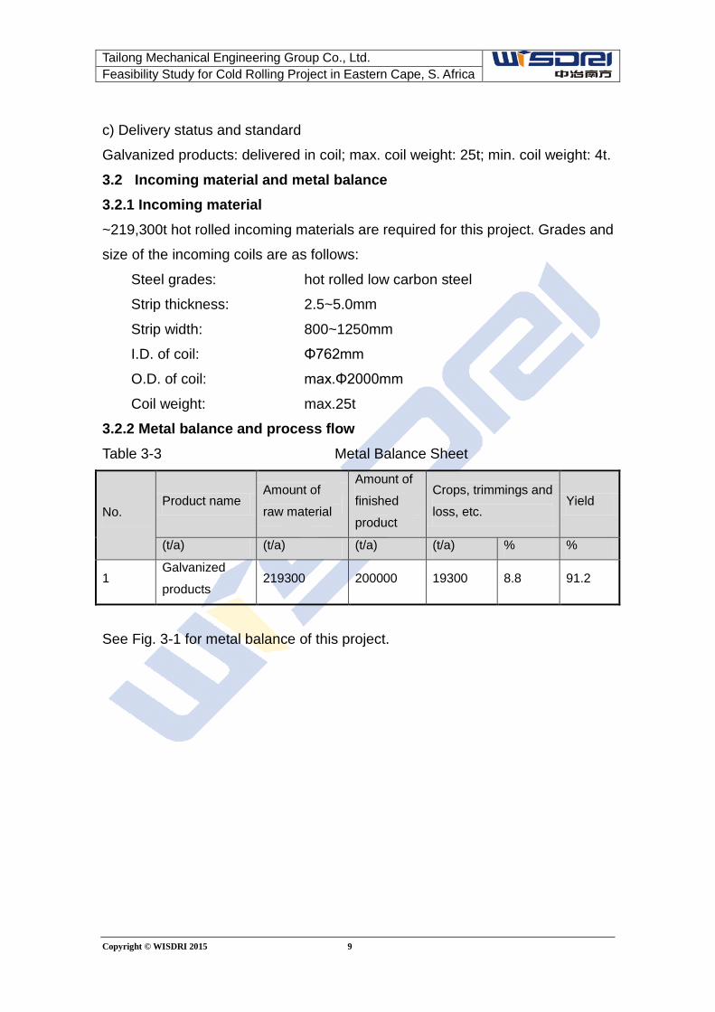
c) Delivery status and standard
Galvanized products: delivered in coil; max. coil weight: 25t; min. coil weight: 4t.
3.2 Incoming material and metal balance 3.2.1 Incoming material ~219,300t hot rolled incoming materials are required for this project. Grades and
size of the incoming coils are as follows:
Steel grades: hot rolled low carbon steel
Strip thickness: 2.5~5.0mm
Strip width: 800~1250mm
I.D. of coil: Φ762mm
O.D. of coil: max.Φ2000mm
Coil weight: max.25t
3.2.2 Metal balance and process flow Table 3-3 Metal Balance Sheet
No. Product name
Amount of
raw material
Amount of
finished
product
Crops, trimmings and
loss, etc. Yield
(t/a) (t/a) (t/a) (t/a) % %
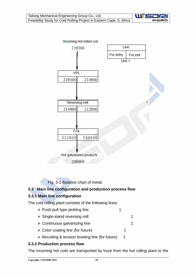
1 Galvanized
products 219300 200000 19300 8.8 91.2
See Fig. 3-1 for metal balance of this project.
Tailong Mechanical Engineering Group Co., Ltd. Feasibility Study for Cold Rolling Project in Eastern Cape, S. Africa
Copyright © WISDRI 2015 10
Fig. 3-1 Balance chart of metal
3.3 Main line configuration and production process flow 3.3.1 Main line configuration The cold rolling plant consists of the following lines:
Push-pull type pickling line 1
Single-stand reversing mill 1
Continuous galvanizing line 1
Color coating line (for future) 1
Recoiling & tension leveling line (for future) 1
3.3.2 Production process flow The incoming hot coils are transported by truck from the hot rolling plant to the
Tailong Mechanical Engineering Group Co., Ltd. Feasibility Study for Cold Rolling Project in Eastern Cape, S. Africa
Copyright © WISDRI 2015 11
raw material warehouse for storage, and then lifted by crane in the warehouse to
the saddle in the entry section of the push-pull type pickling line, where manual
confirmation of coil No., manual removal of strap and coil preparation take place.
The coil is then delivered by coil car to payoff reel. The strip head, after leveling
and scale breaking, enters through steering device to the entry shear for cutting
of the unqualified part before going to hydrochloric acid pickling tank for removal
of scale on strip surface. The pickled strip goes to rinse tank for rinsing before
being sent to hot air dryer for drying. The pickled, rinsed and dried strip goes to
the tension reel. When coil weight or strip length reaches the specified value, it
will be divided at the exit shear. The strip coil is unloaded by coil car and sent to
the exit saddle for strapping and label printing before being lifted by crane to the
storage before the rolling mill.
The pickled coil goes further to the cold rolling process and hot dip galvanizing
process.
The coil for rolling is lifted by crane to entry saddle of the rolling mill, and then
sent by coil car to the payoff reel. The coil, after uncoiling and leveling, goes to
the rolling mill. After two or three wraps of strip head have been built on the reel,
tension is established and a certain reduction is given, the payoff reel, rolling mill
and tension reel are accelerated to the rolling speed for stable rolling. The speed
is decelerated when rolling of one coil is almost finished. After stop, reverse
movement starts for reversing rolling. At the last pass of the rolling, the offgauge
part at the strip tail is cut at the exit shear. Based on different rolling passes, the
rolled coil and pup coil are respectively coiled by two tension reels before being
unloaded to coil car. The coil is then conveyed by the coil car to the rolled coil
storage in galvanizing bay.
The coil is then lifted by crane to the coil car in front of the payoff reel of the
galvanizing line, and unloaded by coil car to mandrel of No.1 and No.2 tension
reel. Height/width measurement, centering and manual strap removal are
carried out before the coil is delivered to the payoff reel. ,
After being loaded to the payoff reel, the strip head goes to pinch flattener for
flattening and entry shear for cutting of the disqualified part. It is then delivered to
the welder for being welded to the tail part of the previous coil. The welded strip,
after weld detection and size notching, is accelerated to the process speed
Tailong Mechanical Engineering Group Co., Ltd. Feasibility Study for Cold Rolling Project in Eastern Cape, S. Africa
Copyright © WISDRI 2015 12
before going to the cleaning section via entry looper. In the cleaning section, the
strip undergoes alkali spraying, alkali brushing, electrolytic cleaning, water
brushing, hot water rinsing and hot air drying to obtain clean surface before
entering the annealing furnace.
The strip undergoes preheating, heating, soaking and cooling in the annealing
furnace before going via snout to the zinc pot for hot dip galvanizing, and then
undergoes cooling, quenching and drying followed by skin passing, tension
leveling and chemical treatment until to the exit looper. The strip from the exit
looper then passes vertical inspection, oiling and cutting processes before
entering No.1 and NO.2 tension reel for coiling.
The coil is delivered by exit No.1 and No.2 coil car to exit saddle for weighing,
strapping and labeling, and then lifted by crane to the finished product storage
for manual packaging and storage.
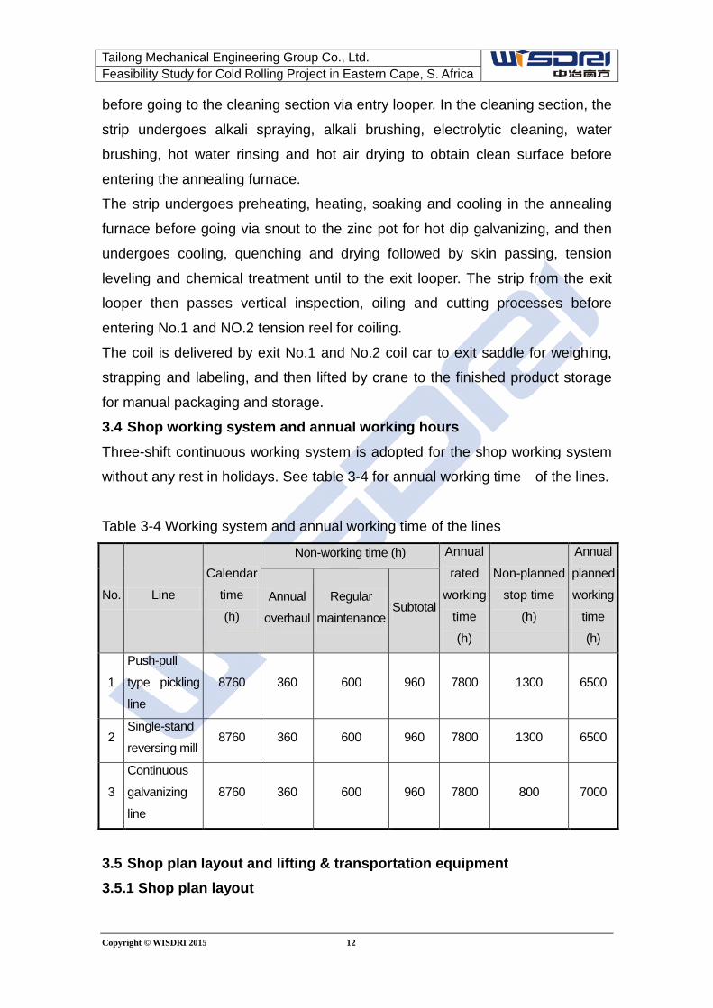
3.4 Shop working system and annual working hours Three-shift continuous working system is adopted for the shop working system
without any rest in holidays. See table 3-4 for annual working time of the lines.
Table 3-4 Working system and annual working time of the lines
No. Line
Calendar
time
(h)
Non-working time (h) Annual
rated
working
time
(h)
Non-planned
stop time
(h)
Annual
planned
working
time
(h)
Annual
overhaul
Regular
maintenance Subtotal
1
Push-pull
type pickling
line
8760 360 600 960 7800 1300 6500
2 Single-stand
reversing mill 8760 360 600 960 7800 1300 6500
3
Continuous
galvanizing
line
8760 360 600 960 7800 800 7000
3.5 Shop plan layout and lifting & transportation equipment 3.5.1 Shop plan layout
Tailong Mechanical Engineering Group Co., Ltd. Feasibility Study for Cold Rolling Project in Eastern Cape, S. Africa
Copyright © WISDRI 2015 13
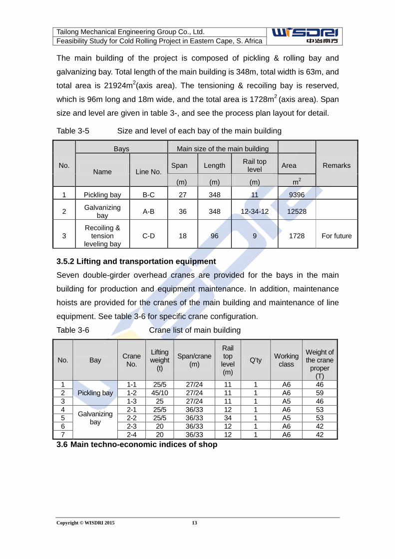
The main building of the project is composed of pickling & rolling bay and
galvanizing bay. Total length of the main building is 348m, total width is 63m, and
total area is 21924m2(axis area). The tensioning & recoiling bay is reserved,
which is 96m long and 18m wide, and the total area is 1728m2 (axis area). Span
size and level are given in table 3-, and see the process plan layout for detail.
Table 3-5 Size and level of each bay of the main building
No.
Bays Main size of the main building
Remarks Name Line No.
Span Length Rail top level Area
(m) (m) (m) m2
1 Pickling bay B-C 27 348 11 9396
2 Galvanizing bay A-B 36 348 12-34-12 12528
3 Recoiling &
tension leveling bay
C-D 18 96 9 1728 For future
3.5.2 Lifting and transportation equipment Seven double-girder overhead cranes are provided for the bays in the main
building for production and equipment maintenance. In addition, maintenance
hoists are provided for the cranes of the main building and maintenance of line
equipment. See table 3-6 for specific crane configuration.
Table 3-6 Crane list of main building
No. Bay Crane No.
Lifting weight
(t)
Span/crane (m)
Rail top
level (m)
Q’ty Working class
Weight of the crane
proper (T)
1 Pickling bay
1-1 25/5 27/24 11 1 A6 46 2 1-2 45/10 27/24 11 1 A6 59 3 1-3 25 27/24 11 1 A5 46 4 Galvanizing
bay
2-1 25/5 36/33 12 1 A6 53 5 2-2 25/5 36/33 34 1 A5 53 6 2-3 20 36/33 12 1 A6 42 7 2-4 20 36/33 12 1 A6 42
3.6 Main techno-economic indices of shop
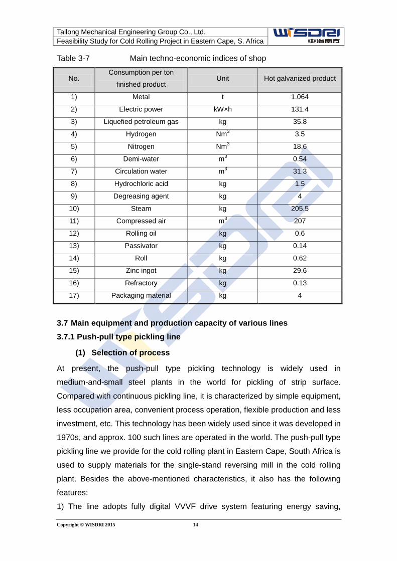
Tailong Mechanical Engineering Group Co., Ltd. Feasibility Study for Cold Rolling Project in Eastern Cape, S. Africa
Copyright © WISDRI 2015 14
Table 3-7 Main techno-economic indices of shop
No. Consumption per ton
finished product Unit Hot galvanized product
1) Metal t 1.064
2) Electric power kW×h 131.4
3) Liquefied petroleum gas kg 35.8
4) Hydrogen Nm3 3.5
5) Nitrogen Nm3 18.6
6) Demi-water m3 0.54
7) Circulation water m3 31.3
8) Hydrochloric acid kg 1.5
9) Degreasing agent kg 4
10) Steam kg 205.5
11) Compressed air m3 207
12) Rolling oil kg 0.6
13) Passivator kg 0.14
14) Roll kg 0.62
15) Zinc ingot kg 29.6
16) Refractory kg 0.13
17) Packaging material kg 4
3.7 Main equipment and production capacity of various lines 3.7.1 Push-pull type pickling line
(1) Selection of process
At present, the push-pull type pickling technology is widely used in
medium-and-small steel plants in the world for pickling of strip surface.
Compared with continuous pickling line, it is characterized by simple equipment,
less occupation area, convenient process operation, flexible production and less
investment, etc. This technology has been widely used since it was developed in
1970s, and approx. 100 such lines are operated in the world. The push-pull type
pickling line we provide for the cold rolling plant in Eastern Cape, South Africa is
used to supply materials for the single-stand reversing mill in the cold rolling
plant. Besides the above-mentioned characteristics, it also has the following
features:
1) The line adopts fully digital VVVF drive system featuring energy saving,
Tailong Mechanical Engineering Group Co., Ltd. Feasibility Study for Cold Rolling Project in Eastern Cape, S. Africa
Copyright © WISDRI 2015 15
reliable operation, convenient maintenance and accurate control.
2) The tension for uncoiling and coiling is automatically controlled.
3) Turbulence shallow tank pickling technology which has remarkable
advantages is designed for the pickling section. Acid liquid is sprayed onto the
strip from both side walls and bottom of acid tank for thorough spray cleaning.
Each pickling section is provided with independent external heating system and
acid circulation system. Each circulation tank is foreseen with acid liquid
temperature measuring device to automatically control the heating condition to
achieve optimum pickling effect by adjusting temperature and concentration of
each pickling section. Thanks to less amount of acid and short starting time, the
strip slides on the thin acid film to reduce scratch on bottom side of the strip.
4) With the four-stage countflow cascade rinse system adopted, a small amount
of rinse water is required to ensure cleaning quality of strip surface.
5) Between 1# squeegee roll and 2# squeegee roll at entry of acid tank are
installed two pairs of spray boom to remove residual liquid on strip surface
during reversing of strip so as to avoid corroding the equipment by liquid acid
carried out by the strip.
6) Automatic coil dividing function is provided at exit of the line.
7) To ensure the strip to enter the side trimmer in a centering way, CPC is
installed at 2# pinch roll to improve side trimming accuracy of the strip.
8) Automatic threading and tailing out are provided for the line.
9) It is designed with automatic tracking system of strip head and tail.
10) ITV monitoring system is installed at entry and exit pulpit to perform dynamic
tracking of running status of the whole line.
(2) Type selection of main equipment:
1) Side trimming equipment
High-accuracy side trimmer with advanced technology is adopted for automatic
adjustment of knife gap (gap and overlap between the two knives).
2) Pickling process
Shallow tank turbulence pickling process is adopted for the design. Improvement
of acid tank structure and increase of acid liquid cycling times increase the
pickling speed, shorten the pickling time and further reduce quantity of acid
tanks.
Tailong Mechanical Engineering Group Co., Ltd. Feasibility Study for Cold Rolling Project in Eastern Cape, S. Africa
Copyright © WISDRI 2015 16
(3) Main technical data of the line
1) Annual capacity: 219,300 (amount at entry side)
2) Incoming material and product
Item Entry Exit
Strength limit: σb≤590MPa σb≤590MPa
Yield limit: σs≤345MPa σs≤345MPa
Strip thickness: 2.5~5.0mm 2.5~5.0mm
Strip width: 800~1250mm 800~1250mm
I.D. of coil: ∅762mm Φ610 mm
O.D. of coil: max∅2000mm max∅2000mm
Coil weight: max.25t max.25t
3) Line data
Line speed:
Process speed: max.50m/min
Threading speed: max.50m/min
Jogging speed: 20m/min
Pickling data:
Pickling capacity: max.42t/h
Iron loss from pickling: max.0.4%
Pickling type: Venturi turbulence pickling
Design of acid tank: 2, total effective length: 25m(12.5m for each)
Rinsing type: Cascade compact type rinse
(4) Main equipment composition of the line
Entry coil saddle, entry coil car, snubber roll, payoff reel, peeler & deflector roll,
1# side guide roll, 5-roll pinch leveler, crop shear & scrap collecting device, taper
shear, pickling tank, rinse tank, acid circulation system, rinse water circulation
system, hot air dryer, fume exhausting & cleaning system of pickling and
cleaning system, squeegee roll, hot air dryer with side blowing device, 1# pinch
roll, pivoting table of looper, 2# side guide roll, 2# pinch roll (with CPC), side
trimmer, scrap box & car, 3-roll tensioning device, inspection table, crop shear &
scrap collecting device, 3# side guide roll, exit deflector roll, tension reel (with
EPC), exit coil car, exit coil saddle (with weighing device), manual strapping
Tailong Mechanical Engineering Group Co., Ltd. Feasibility Study for Cold Rolling Project in Eastern Cape, S. Africa
Copyright © WISDRI 2015 17
device, entry hydraulic station, exit hydraulic station, pneumatic system,
interconnecting piping, steel structure platform, special tool and anchor bolt.
3.7.2 Single-stand reversing mill
(1) Description of type selection
The cold rolling mill is the key equipment for cold rolling production; the rolling
mill is of great significance to surface quality, thickness tolerance and
mechanical property of strip in addition to the incoming hot rolled material.
Several types of rolling mills could be used for producing cold rolling strips, such
as CVC rolling mill, 6-hi UCM or 12-h reversing mill, etc.
Considering that the project mainly produces thin base plates for galvanizing, it
adopts 12-h single stand reversing mill with high rolling capacity and strong
shape control, which is equipped with hydraulic thickness automatic control
system to produce thin steel sheet with good shape and high thickness
accuracy.
Based on process characteristics, process equipment configuration of the line
has the following features:
1) Fully digital DC speed control and thyristor power supply are adopted for
the main rolling mill, payoff reel and both tension reels (one at entry and
one at exit). The line is controlled by PLC, and automatic tension control
system is foreseen.
2) Hydraulic expanding/collapsing mandrel is adopted for the two tension
reels, which are driven by two D.C. motors. The two motors work
simultaneously in case of big tension and one work in case of small
tension.
3) It adopts fully hydraulic screwdown and computer-based automatic
gauge control (AGC) system. The hydraulic AGC is provided with
two-level computer control, including such functions as constant roll gap
control, constant tension control, thickness pre-control, supervision and
mass flow control, etc.
4) Emulsion lubrication cooling system is adopted for process lubrication,
and three-stage filter is provided.
5) Centralized oil lubrication system is adopted for main gearbox and
Tailong Mechanical Engineering Group Co., Ltd. Feasibility Study for Cold Rolling Project in Eastern Cape, S. Africa
Copyright © WISDRI 2015 18
gearbox of the two tension reels.
6) It is provided with sensitive axial and radial roll shape adjustment
mechanism.
7) Roll compensation adjustment mechanism is provided.
8) CPC automatic centering function is foreseen for the payoff reel.
9) Quick change device is provided for work roll, intermediate roll and roll
cartridge.
10) Interlock mechanism is foreseen for movement of the rolling mill.
11) The electrical system of the rolling mill includes overload protection,
strip breakage protection and emergency stop safety protection systems;
the rolling mill and the tension reels have strip tail automatic deceleration
function and accurate stop function; the tension reel has wrap memory
function.
12) It is provided with speed control of rolling mill, speed/tension control
of payoff reel and tension reel and digital display.
13) The level of the passline could be quickly adjusted.
14) The rolling mill is provided with complete operation & supervision
display system, fault diagnosis and alarming system. The process data
of rolling could be displayed and stored. Meanwhile, trend curve could
be used to display, on real time basis, the change trend of the process
data such as speed of the mill, rolling pressure, roll gap, tension,
thickness, etc.
15) The line is provided with presetting system of process data as well
as measuring and display system of process data and key equipment
data.
(2) Main technical data of the line
1) Annual capacity: 215,000t (amount at entry)
2) Raw material and finished product
Item Entry Exit
Strip thickness: 2.5~5.0mm 0.4~2.5 mm
Strip width: 800~1300mm 800~1300mm
I.D. of coil: Φ610mm Φ610mm
Tailong Mechanical Engineering Group Co., Ltd. Feasibility Study for Cold Rolling Project in Eastern Cape, S. Africa
Copyright © WISDRI 2015 19
O.D. of coil: Φ1000~2000 mm Φ1000~2000mm
Coil weight: Max. 25t Max. 25 t
3) Data of line
Type of rolling mill: single-stand 12-h reversing mill
Rolling speed: Max.700 m/min
(3) Main equipment composition of the line
Main rolling mill, main drive unit, payoff reel, tension reel, 3-roll flattener, bridle
roll unit, cross cut shear, thickness gauge, 4-roll deoiler, side guide, hold-down
plate, loading/unloading car, saddle, wrapper, hydraulic system, process &
bearing lubrication system and equipment lubrication system.
3.7.3 Continuous galvanizing line
(1)Type selection of equipment
It is a continuous, multi-functional production line of high efficiency, integrated
with such processes as strip surface precleaning, annealing, hot dip galvanizing,
zinc coating annealing, after-pot cooling, skin passing, passivation, oiling, side
trimming, dividing and surface defect inspection, etc.
According to the above process characteristics, configuration of the process
equipment has the following features based on the type selection of the CGL:
(1) It adopts improved Sendzimir production process, featuring well-proven and
reliable technology, less investment, easy operation and high thermal efficiency,
etc.
(2) Cleaning quality of the cleaning section: magnetic filter and automatic alkali
liquid concentration control are arranged in the alkali cleaning circulation system
to keep the concentration of the alkali liquid during the cleaning and reduce
impurity content in the alkali liquid.
(3) It adopts the annealing furnace featuring big heating capacity, high cooling
speed, high accuracy of temperature control and good roll shape control to meet
the annealing requirements of multiple grades and high quality.
(4)The thickness of the zinc coating could be controlled by adjusting pressure
and flow of injection air at knife lip via adjusting rotating angle of one sleeve in
the knife chamber.
(5) Roller coating type passivation equipment is adopted.
(6) In order to prevent the dirt (zinc dross) on the roll from damaging the strip
Tailong Mechanical Engineering Group Co., Ltd. Feasibility Study for Cold Rolling Project in Eastern Cape, S. Africa
Copyright © WISDRI 2015 20
surface, scraper is installed on the rolls which could easily damage the strip after
annealing so as to avoid strip damage caused by defect on roll by constantly
scraping off the impurities from the roll.
(7) High-accuracy roll drive system (A.C. vector control drive system) is adopted
for the whole line to ensure synchronization between the strip and the roll for
preventing strip damage.
(8) Vertical inspection station is arranged at the exit section to perform shape
inspection on marble table for the strip in case of stoppage of the line.
(9) Energy saving device is provided for overheated water conversion by waste
gas of furnace and reutilization of water.
(2) Main process data of the line
(1) Annual capacity of the line: 212,800 t/a
(2) Incoming material and product
Item Entry Exit
Strip thickness: 0.4~2.5 mm 0.4~2.5 mm
Strip width: 800~1250mm 800~1250mm
I.D. of coil: Φ610mm Φ508mm
I.D. of coil: Φ1000~2000 mm Φ1000~2000mm
Coil weight: Max. 25t Max. 25 t
(3) Data of the line
Speed at entry section: Max. 200m/min
Speed at process section: Max. 150m/min
Speed at exit section: Max. 200m/min
Entry looper: ~440m
Exit looper: ~360m
Heating capacity of annealing furnace: Max.37t/h
Q’ty of zinc pot: 1
(4) Main equipment composition of the line
Entry coil conveying, coil loading, payoff reel, entry shearing equipment & scrap
handling device, welder, strip surface cleaning equipment, entry looper,
horizontal annealing furnace, hot galvanizing equipment, cooling device, skin
pass mill, post treatment (passivation/anti-finger print) equipment, exit looper,
Tailong Mechanical Engineering Group Co., Ltd. Feasibility Study for Cold Rolling Project in Eastern Cape, S. Africa
Copyright © WISDRI 2015 21
horizontal inspection equipment, oiler, exit shear, coiling & unloading
equipment and coil conveying, etc.
Tailong Mechanical Engineering Group Co., Ltd. Feasibility Study for Cold Rolling Project in Eastern Cape, S. Africa
Copyright © WISDRI 2015 22
4 Power supply and electrical control 4.1 Overview Production scale of the project is 200,000t, mainly including the following
production lines:
Push-pull type pickling line: 1
Single-stand reversing mill 1
Continuous hot galvanizing line 1
Color coating line (for future) 1
Recoiling & tension leveling line (for future) 1
Relevant utility facilities, such as acid regeneration plant, roll shop,
waste water treatment plant, circulation water station, air compressor
station, demi-water station, and 10kV switchgear station
4.2 Power supply HV (3-phase A.C.) 10kV
LV (3-phase A.C.) 380V, 220V(for lighting)
Frequency 50HZ
Control voltage (single phase A.C.) 220V AC
Power supply of solenoid valve 24V DC, 220V AC
Power supply of signal lamp 24V DC
PLC power supply 24V DC
Remarks: Voltage of some A.C. motors with big capacity will be determined as
per requirement of electrical package supplier and process.
4.3 Power supply & distribution solution and facilities 4.3.1 Power supply & distribution solution
One 10kV switchgear station is designed to supply power to the main production
line and relevant utility facilities, and substation of lower level could be foreseen
as necessary. The 10kV power of the switchgear station is fed from outside.
Total installed capacity of the project is approx. 24400kW, including approx.
9682kW for the reversing mill, approx. 6710kW for the CGL, 3746KW for future
and 2691kW for auxiliary power of the line and utility facilities of the plant.
Total calculated load of the project is Pjs=12080kW, Sjs=14209kVA, and natural
power factor is approx. 0.85.
Annual power consumption of shop is 4.83×10⁷kWh.
Tailong Mechanical Engineering Group Co., Ltd. Feasibility Study for Cold Rolling Project in Eastern Cape, S. Africa
Copyright © WISDRI 2015 23
The 10kV switchgear station and LV electrical room are built together, including
HV power distribution room and control room. The location of the switchgear
station is preliminarily determined close to the electrical room of the rolling mill
nearby the main building.
4.3.2 Main power supply & distribution facilities
Incoming feeder of the 10kV switchgear station and sectionalized switchgear
cubicle could be controlled on micro-processor-based background in a
centralized manner, and the transformer circuit could be directly operated on
switchgear cubicle or the micro-processor-based background.
Micro-processor-based line and transformer protection device are adopted for
incoming feeder and outgoing feeder of the 10kV switchgear station. One set of
micro-processor-based supervision device is arranged in the electrical control
room to perform control, protection, measurement, emergency supervision,
emergency signal display, tracing & recording of emergency and printing of
report, historical data and picture, etc. for all the 10kV circuits by communication
management computer. Communication interface is reserved for easy
communication with upper-level switchgear station in future.
Digital type comprehensive 10kV energy meter in installed at 10kV incoming
feeder of the switchgear station for measuring current, active power, reactive
power and power factor, etc. Voltmeter is installed at busbar side as
conventionally and ammeter at various outgoing feeders.
KYN28-12 central fixed type HV switchgear cubicle is used as 10kV HV cubicle,
and it is equipped with vacuum circuit and spring operating mechanism. The
breaking current is 31.5kA.
It adopts DC220V 100/100Ah D.C. power supply device with maintenance free
lead acid accumulator.
Domestic micro-processor-based protection device is adopted.
4.4 LV power supply & distribution system Transformer and load center are designed as per lines to reduce loss and
ensure reliable power supply. 3-phase-&-3-wire system is adopted for power
supply & distribution system of main drive of the line, and 3-phase-&-4-wire
system for lighting, the main building crane and other power supply & distribution
systems. 1 set of UPS is provided for each line to power the computer, PLC and
Tailong Mechanical Engineering Group Co., Ltd. Feasibility Study for Cold Rolling Project in Eastern Cape, S. Africa
Copyright © WISDRI 2015 24
special instrument.
The line load is powered by one circuit; crane, lighting and utility facilities are
powered by two circuits.
4.5 Electrical drive and control of line 4.5.1Push-pull type pickling line
Total installed capacity of the line is approx. 1573kW, including 665.5kW for
variable-speed motors and 907.5kW for constant-speed motors.
Fully digital A.C. speed controlled device is used for power supply to
A.C.speed-controlled motor. Impulse encoder is used as speed feedback to AC
drive control system for realizing closed loop control; the drive unit
communicates via network with the upper level basic automation system.
A.C. constant-speed motor is powered by motor control center (MCC) where
remote I/O station is arranged; it is communicated via network with PLC.
The basic automation control system of the line is composed of PLC and
industrial control computer. Industrial Ethernet is used for connection between
PLCs and between PLC and HMI, and field bus for connection between PLC and
drive unit. In order to reduce cable and construction fee, remote I/O stations will
be arranged as much as possible, and it is connected via network with PLC. The
remote I/O station is mainly arranged in operating desk/box, MCC cubicle and
single equipment control cubicle area.
Including the following main control functions:
• Automatic threading
• Speed control
• Tension control
• Welder control
• Looper control
• Automatic deceleration
• Emergency stop control
• Sequence control
• Strip tracking
• Operation and supervision
• Fault display and alarming
Tailong Mechanical Engineering Group Co., Ltd. Feasibility Study for Cold Rolling Project in Eastern Cape, S. Africa
Copyright © WISDRI 2015 25
• Recording and printing
4.5.2 Single-stand reversing mill
Total installed capacity of the single-stand reversing mill is approx. 9682kW,
including 9100 kW for A.C. speed-controlled motor, and 582 kW for A.C.
constant-speed motor.
A.C. motor is adopted for main drive (including payoff reel, rolling mill and
tension reel); fully digital A.C. speed control system is adopted; power supply
model and power element of frequency converter of the main drive will be
determined in the next phase.
All the other AC speed controlled motors will be powered by fully digital AC
speed control device. Impulse encoder is used as speed feedback to AC drive
control system for realizing closed loop control; the drive unit communicates via
network with the upper level basic automation system.
A.C. constant-speed motor is powered by motor control center (MCC) where
remote I/O station is arranged; it is communicated via network with PLC.
The basic automation control system of the line is composed of PLC and
industrial control computer. Industrial Ethernet is used for connection between
PLCs and between PLC and HMI, and field bus for connection between PLC and
drive unit. In order to reduce cable and construction fee, remote I/O stations will
be arranged as much as possible, and it is connected via network with PLC. The
remote I/O station is mainly arranged in operating desk/box, MCC cubicle and
single equipment control cubicle area.
Including the following main control functions:
• Speed control
• Tension control
• Automatic gauge control of strip
• Strip shape control
• Bending roll control
• Data acquisition and processing
• Sequence control
• Exchange with process data
• Emergency supervision and diagnosis
Tailong Mechanical Engineering Group Co., Ltd. Feasibility Study for Cold Rolling Project in Eastern Cape, S. Africa
Copyright © WISDRI 2015 26
• Recording and printing
4.5.3 Continuous galvanizing line
Total installed capacity of the line is approx. 6710kW, including approx. 2100kW
for speed-controlled motor and 4610kW for constant-speed motor & welder. One
diesel generator unit is designed as emergency power to supply power to the
control cubicle of zinc pot, furnace bottom rolls and pump unit of the water
cooling system in emergency case of normal power source.
All the other AC speed controlled motors will be powered by fully digital AC
speed control device. Impulse encoder is used as speed feedback to AC drive
control system for realizing closed loop control; the drive unit communicates via
network with the upper level basic automation system.
A.C. constant-speed motor is powered by motor control center (MCC) where
remote I/O station is arranged; it is communicated via network with PLC.
The basic automation control system of the line is composed of PLC and
industrial control computer. Industrial Ethernet is used for connection between
PLCs and between PLC and HMI, and field bus for connection between PLC and
drive unit. In order to reduce cable and construction fee, remote I/O stations will
be arranged as much as possible, and it is connected via network with PLC. The
remote I/O station is mainly arranged in operating desk/box, MCC cubicle and
single equipment control cubicle area.
Including the following main control functions:
• Speed control
• Tension control
• Looper control
• Material tracking
• Interlock sequence control
• Operation and supervision
• Fault display, alarming, recording and printing
4.5.4 Acid regeneration plant
Total installed capacity of the ARP is approx. 200kW. AC speed-controlled motor
will be powered by fully digital AC speed control device, while AC
constant-speed motor by MCC. One set of electrical-instrument integrated
control system is designed for the ARP.
Tailong Mechanical Engineering Group Co., Ltd. Feasibility Study for Cold Rolling Project in Eastern Cape, S. Africa
Copyright © WISDRI 2015 27
4.5.5 Color coating line (for future)
Total installed capacity of the line is approx. 1876kW, including 1226kW for
speed-controlled motor and 650kW for constant-speed motor.
4.5.6 Recoiling & tension leveling line (for future)
Total installed capacity of the line is approx. 1870kW, including 1400kW for
speed-controlled motor and 470kW for constant-speed motor and welder.
4.6 Electrical room and pulpit One electrical room is designed for the PPL, one electrical room for the
single-stand reversing mill, entry & exit electrical rooms (2 in total) for CGL and
one electrical room for utility facilities. Refer to the process layout for specific
location.
The pulpit is arranged as per process requirement.
4.7 Lighting and movable facilities of the main building Lighting area of the main building is approx. 23652m2. Two transformers are
foreseen for supplying power to the lighting and crane. LV tie switch is arranged
at secondary side of the two transformers to ensure that the other transformer
could be switched over by the tie switch to supply power in case that one
transformer fails for the purpose of increasing power supply reliability of lighting
and movable facilities of the whole plant. The lighting transformer is arranged in
the electrical room of the pickling line.
Lighting distribution boxes, dispersedly arranged in shop, are powered by the
lighting load center in the power distribution room in a radial way. The lighting in
the main building is powered by different lighting distribution boxes in a
crossfeed manner so as to ensure reliability and continuity of the power supply.
4.8 Crane of the main building 8 cranes are arranged in the main building with total installed capacity approx.
655kW. Two transformers are foreseen for supplying power to the lighting and
crane. LV tie switch is arranged at secondary side of the two transformers to
ensure that the other transformer could be switched over by the tie switch to
supply power in case that one transformer fails for the purpose of increasing
power supply reliability of lighting and movable facilities of the whole plant. The
lighting transformer is arranged in the electrical room of the pickling line.
4.9 Utility facilities
Tailong Mechanical Engineering Group Co., Ltd. Feasibility Study for Cold Rolling Project in Eastern Cape, S. Africa
Copyright © WISDRI 2015 28
The utility facilities mainly include acid regeneration plant, waste water treatment
plant, circulation water station, air compressor station and demi-water station,
etc.
Total installed capacity of the utility facilities is approx. 1835.5kW. The substation
with two transformers is arranged in the circulation water station. LV tie switch is
arranged at secondary side of the two transformers to ensure that the other
transformer could be switched over by the tie switch to supply power in case that
one transformer fails for the purpose of increasing the reliability of power supply.
Independent load center and MCC are provided for each station, and PLC
control system is adopted.
4.10 Cabling and fire fighting 4.10.1 Cabling
The cable is laid in a combined way of cable channel, tunnel, spreading room,
tray and conduit, etc.
4.10.2 Fire prevention of cable
Explosive area and fire protection zone shall be avoided for cable routing;
otherwise, corresponding fire prevention measures shall be taken.
Fire separator and fire caulking material shall be used to block the entry and exit
of cable in electrical room and pulpit.
Fire prevention trunking is arranged at regular interval for cables in cable
channel, cable trench, cable spreading room and cable tray.
Fire alarming device is installed at transformer room, electrical room, pulpit,
cable spreading room and cable tunnel, etc.
4.11 Lightning protection and earthing The earthing system is designed as follows:
Lightning protection and earthing to be arranged as per buildings and
structures;
Protection earthing of electrical equipment and electrical component,
etc.
Working earthing of power supply system
Independent earthing system for PLC and variable-frequency and
speed control device, etc.
The final earthing system will be designed based on actual conditions.
Tailong Mechanical Engineering Group Co., Ltd. Feasibility Study for Cold Rolling Project in Eastern Cape, S. Africa
Copyright © WISDRI 2015 29
5 Utility facilities 5.1 Overview Tailong Mechanical Engineering Group Co., Ltd. plans to invest in Eastern Cape
to build a cold rolling plant mainly for producing galvanized products with
production scale of 200,000t/a galvanized products. This cold rolling plant is
located at an industrial park in Eastern Cape, South Africa.
Various energy media are required for the lines of the project, mainly including
compressed air, circulation water, demi-water, industrial water, living water,
emergency water, steam, liquefied petroleum gas, nitrogen and hydrogen.
It is going to building circulation water station, waste water treatment plant, air
compressor station and demi-water station in the cold rolling plant to supply
compressed air, circulation water, demi-water and emergency water necessary
for production. Other water, steam, liquefied petroleum gas, nitrogen and
hydrogen required for production will be supplied to the location nearby the plant
by the industrial park.
The production waste water from the plant will be treated by the waste water
treatment station in the plant before discharging.
5.2 Water supply & drainage facilities 5.2.1 Overview
Tailong Mechanical Engineering Group Co., Ltd plans to invest in Eastern Cape
to build a cold rolling plant mainly for producing galvanized products with
production scale of 200,000t/a galvanized products, including pickling line,
rolling mill and CGL. The corresponding facilities include circulation water
treatment facility, waste water treatment facility, ARP and water supply &
drainage pipe network inside and outside shop.
5.2.2 Current status of external pipe network and production water amount
Living water, production water, domestic sewage pipe and rain water pipe are
provided around the project to meet the requirements of this project.
5.2.2.1 Production water amount required for this project
Table 5-1 Production water amount
No. Designation Water flow m3/h
1 Makeup water of
circulation water
18
Tailong Mechanical Engineering Group Co., Ltd. Feasibility Study for Cold Rolling Project in Eastern Cape, S. Africa
Copyright © WISDRI 2015 30
2 Makeup water of
demi-water station
32
3 Water consumption of the
main building
10
Total 60
Production water amount of the project is 60m3/h.
5.2.3 Circulation water facilities
5.2.3.1 Circulation water flow
Circulation water flow Q=1200 m3/h, emergency water Q=30 m3/h
Feed temperature of circulation water≤33℃, return temperature of
circulation water≤43℃
Feed pressure of circulation water: 0.4~0.5MPa
5.1.3.2 Process flow of circulation water
Cooling water from consumer flows in pipe via residual pressure to cooling tower,
and the cooled water enters the cold water tank followed by being boosted and
supplied by main circulation pump to the consumer for recycling. The designed
circulation rate is 98.5%, and the concentration times is 5. Designed makeup
water flow is 18m3/h, and blowdown water flow is 4m3/h.
Production makeup water is required as water amount of the system is reduced
due to splashing and evaporation of the cooling tower as well as system
blowdown during normal operation of the whole system.
Circulation water is supplied in normal case and the main water feed pump is
provided with two circuits of independents power supply. Emergency water is
sourced from the emergency water tower.
5.2.3.3 Main equipment and construction
Cold water tank, main circulation pump, FRP cooling tower, side-stream filter,
emergency water tower, bypass pump, pump house and dosing facilities, etc.
5.2.4 Waste water treatment facilities
5.2.4.1 Amount of waste water system
Waste water from the line includes waste emulsion, alkali waste water, acid
waste water and coating waste water; the last two will be entrusted to external
company for treatment.
The discharging amount is as follows:
Tailong Mechanical Engineering Group Co., Ltd. Feasibility Study for Cold Rolling Project in Eastern Cape, S. Africa
Copyright © WISDRI 2015 31
Waste emulsion: 3 m3/h acid waste water: 9 m3/h
Alkali waste water: 9 m3/h coating waste water: 1 m3/h
Treatment capacity of the system is as follows:
Alkali waste water: 15 m3/h
Waste emulsion: 4 m3/h
5.2.4.2 Effluent water indices of WWTP
PH:6~9 SS:≤ 30mg/l
Oil: ≤ 3mg/l COD:≤ 60mg/l
5.2.4.3Process flow of waste water
(1) Waste emulsion treatment system
Oil/emulsion bearing waste water from lines→→buffer tank→→ lift pump →→
reaction tank→→flocculation tank→ air floatation device→→outlet water to alkali
waste water treatment system
Concentrated oil from buffer tank → emulsion breaking tank→outlet water to oily
waste water buffer tank
Oily sludge→→filter press of waste water treatment system
(2)Alkali waste water treatment system
Alkali waste water from the lines→→ buffer tank→pump→stage-1 reaction
tank→→stage-1 flocculation tank→→stage-1 air floatation tank →→stage-2
reaction tank→→stage-2 flocculation tank→→stage-2 air floatation tank→→final
PH regulation tank→→intermediate water tank →→cooling tower→contact
oxidation reaction tank →→inclined plate sedimentation tank→→quartz sand
filter tank→→discharging
Part of the sludge from air floatation tank→→ pump→→sludge concentration
tank→→plate & frame filter press→→sludge transported to outside
5.2.4.4 Main facilities
(1)Oil/waste emulsion bearing waste water treatment system
Waste emulsion buffer tank, waste emulsion lift pump, waste oil collection tank,
emulsion breaking tank, emulsion waste water sump pit, drainage pump,
reaction tank, flocculation tank and air floatation tank.
(2) Alkali waste water treatment system
Alkali waste water conditioning tank, alkali waste water lift pump, stage-1
reaction tank, stage-1 flocculation tank, stage 1 air floatation tank, stage-2
Tailong Mechanical Engineering Group Co., Ltd. Feasibility Study for Cold Rolling Project in Eastern Cape, S. Africa
Copyright © WISDRI 2015 32
reaction tank, stage-2 flocculation tank, stage-2 air floatation tank, intermediate
water tank, cooling tower, contact oxidation reaction tank, sedimentation tank,
quartz sand filter, dross tank, dross pump and filter press.
(3) Chemical dosing system
Sulphuric acid dosing facility, NaOH dosing facility, PAM dosing facility and PAC
dosing facility
5.2.5 Acid regeneration facility
Annual pickling amount: 219,000t/a
Iron loss from pickling: 0.40%
Working time of the pickling line:
Net production hours: 6000h/a (production time for calculating the acid
regeneration capacity)
Waste acid amount: 1300 l/h
Designed acid regeneration capacity: 2100l/h, with spray roasting adopted.
5.2.5.1 Process flow
The waste acid enters the separator at the bottom of the preconcentrator of the
acid regeneration plant; part of the acid is circulated by circulation pump in the
preconcentrator, and the other part is sent to the roaster. During the circulation
process, the waste acid undergoes full heat exchange with the hot gas from the
roaster, and the concentrated waste acid to the roaster is boosted and delivered
by the liquid feed pump of the roaster to the two booms at the top of the roaster.
In the roaster, the acid drop and FeCl2 react in the following way under a certain
temperature:
4Fe Cl2+4H2O+O2=2Fe2O3+8HCl
The solid Fe2O3 from reaction falls at the cone bottom of the roaster, and is
discharged via breaker and rotary discharging valve. Water, HCl gas and fine
Fe2O3 go from the top of the roaster to the double-cyclone separator, and
separated oxide powder is returned via the rotary valve to the roaster. The
dedusted gas enters the preconcentrator.
The gas from the preconcentrator with low HCl gas temperature and low content
of iron powder goes to the bottom of the absorption column, where the gas
contacts with the counterflow rinse water from top to bottom, and the HCl in the
waste gas is absorbed in water to form hydrochloric acid solution. The gas from
Tailong Mechanical Engineering Group Co., Ltd. Feasibility Study for Cold Rolling Project in Eastern Cape, S. Africa
Copyright © WISDRI 2015 33
the absorption column goes to stage 1 & 2 scrubber followed by being
exhausted via chimney to atmosphere.
The whole acid regeneration plant is kept at a constant negative pressure by
variable frequency and speed regulation control of the exhaust fan so as to avoid
leakage of HCl gas from the system. The gas is sucked by the exhaust fan
through roaster, preconcentrator, absorption column and scrubber up to the
chimney for discharging to atmosphere.
The oxide powder discharged from the bottom of the roaster is sucked to the
storage bin by the negative pressure caused by the exhaust fan. It is then
discharged via the rotary valve at the bottom of the bin to the bagging machine
with weigher for packaging and bag sealing for sale.
5.2.5.2 Main equipment and construction
Waste acid storage tank, regenerated acid storage tank, new acid storage tank,
rinse water storage tank, new acid pump, waste acid pump, circulation pump of
preconcentrator, acid feed pump of roaster, regenerated acid pump, rinse water
pump, water feed pump of absorption column, water feed pump of scrubber,
roaster, double-cyclone separator, preconcentrator, absorption column, 1#
scrubber, 2# scrubber, exhaust fan and pipe system and oxide powder station.
5.2.6 Water supply & drainage pipe network inside/outside shop
Mainly including the following content:
● Circulation water and emergency water pipe network
● Production fire water pipe network
● Oily waste water pipe network
● Acid waste water pipe network
● Coating waste water pipe network
● Alkali waste water pipe network
● Living water supply system
● Production water, living water and rain water drainage system
(1) Indirect circulation water and emergency water pipe network
Feed and return main of the indirect circulation water, with diameter D530x9 and
material of steel, are embedded from the circulation water pump house to the
main building, and then laid overhead along the building column to various
consumers. Emergency water pipe, with diameter DN100 and material of steel,
Tailong Mechanical Engineering Group Co., Ltd. Feasibility Study for Cold Rolling Project in Eastern Cape, S. Africa
Copyright © WISDRI 2015 34
is embedded from the circulation water pump house to the main building, and
then laid overhead along the building column to various consumers.
(2) Production fire water pipe
Circular pipe network is adopted for indoor production fire water; the pipe
diameter is D159x6, and a fire hydrant is arranged every 30m. Circular pipe
network is adopted for outdoor production fire water; and a fire hydrant is
arranged every 120m. Two TOPs are connected from external pipe network to
the project.
(3) Oil/emulsion bearing pipe
Water drain pump (with seamless steel pipe) is installed at mill oil cellar, oil fume
scrubbing system and emulsion room. The oil/emulsion bearing pipe is laid
overhead along the building column to the outside of shop, and then laid via rack
to the water treatment station.
(4) Acid waste water pipe
The acid waste water pipe (dia.: DN80 and material: PPH) from the pickling line
is laid to the shop outside, and then piped to tank car for regular transportation to
outside.
(5) Coating waste water pipe
The coating waste water pipe (dia.: DN80 and material: stainless steel) from the
CGL is laid to the shop outside, and then piped to tank car for regular
transportation to outside.
(6) Alkali waste water pipe
The alkali waste water pipe (dia.: Φ108×4.5 and material: seamless steel) from
the CGL is laid overhead to the alkali waste water buffer tank of the waste water
treatment plant.
Drain water from sump pit of payoff reel and tension reel is respectively lifted by
pump and piped (seamless steel) overhead or along the trench to diluted alkali
waste water pipe of the main building. One submerged pump and valve are
arranged respectively in the sump pit.
(7) Living water pipe
Living water is taken from TOP of external pipe network to this project for water
supply to sanitary facility. Galvanized steel pipe with TOP dia. DN80 is used, and
the water consumption is 8m3/h.
Tailong Mechanical Engineering Group Co., Ltd. Feasibility Study for Cold Rolling Project in Eastern Cape, S. Africa
Copyright © WISDRI 2015 35
(8) Water drain pipe
Drain water from sump pit of entry and exit looper of the line is lifted respectively
by pump and piped in an overhead or embedded way to TOP of the main
building. Seamless pipe is adopted. Submerged pump and valve are arranged in
the sump pit, 1 at each sump pit.
Roof rain water, ground rain water and production water drained reaching
related standards after treatment are collected and discharged to rain water pipe
network of the plant. Recurrence interval for rain water is designed as 5 years,
and checked as 10 years.
The living drain water is collected and discharged to the living water pipe
network of the plant.
5.2.7 Main techno-economic indices
Production water: 60m3/h
Discharging waste water reaching related standards: 28 m3/h
5.3 Thermal power facilities 5.3.1 Overview
The thermal power facilities for the cold rolling project include:
● Compressed air supply & air compressor station
● Steam supply
● Demi-water supply and demi-water station
● Thermal power pipe inside/outside shop
5.3.2 Compressed air supply
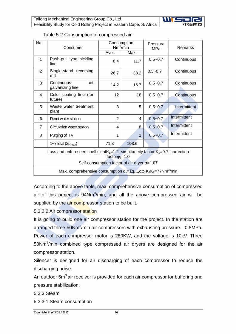
5.3.2.1 Consumption of compressed air
Consumption of compressed air of the project is shown in the following table:
Tailong Mechanical Engineering Group Co., Ltd. Feasibility Study for Cold Rolling Project in Eastern Cape, S. Africa
Copyright © WISDRI 2015 36
Table 5-2 Consumption of compressed air No.
Consumer Consumption
Nm3/min Pressure
MPa Remarks Ave. Max.
1 Push-pull type pickling line 8.4 11.7 0.5~0.7 Continuous
2 Single-stand reversing mill 26.7 38.2 0.5~0.7 Continuous
3 Continuous hot galvanizing line 14.2 16.7 0.5~0.7 Continuous
4 Color coating line (for future)
12 18 0.5~0.7 Continuous
5 Waste water treatment plant
3 5 0.5~0.7 Intermittent
6 Demi-water station 2 4 0.5~0.7 Intermittent
7 Circulation water station 4 8 0.5~0.7 Intermittent
8 Purging of ITV 1 2 0.5~0.7 Intermittent
1~7 total (Σqmax) 71.3 103.6
Loss and unforeseen coefficientK1=1.2, simultaneity factor K2=0.7, correction factorφ1=1.0
Self-consumption factor of air dryer α=1.07
Max. comprehensive consumption qv=Σqmaxαφ1K1K2=77Nm3/min
According to the above table, max. comprehensive consumption of compressed
air of this project is 94Nm3/min, and all the above compressed air will be
supplied by the air compressor station to be built.
5.3.2.2 Air compressor station
It is going to build one air compressor station for the project. In the station are
arranged three 50Nm3/min air compressors with exhausting pressure 0.8MPa.
Power of each compressor motor is 280KW, and the voltage is 10kV. Three
50Nm3/min combined type compressed air dryers are designed for the air
compressor station.
Silencer is designed for air discharging of each compressor to reduce the
discharging noise.
An outdoor 5m3 air receiver is provided for each air compressor for buffering and
pressure stabilization.
5.3.3 Steam
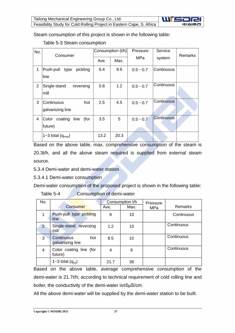
5.3.3.1 Steam consumption
Tailong Mechanical Engineering Group Co., Ltd. Feasibility Study for Cold Rolling Project in Eastern Cape, S. Africa
Copyright © WISDRI 2015 37
Steam consumption of this project is shown in the following table:
Table 5-3 Steam consumption
No. Consumer
Consumption (t/h) Pressure
MPa Service
system Remarks Ave. Max.
1 Push-pull type pickling
line
6.4 9.6 0.5~0.7 Continuous
2 Single-stand reversing
mill
0.8 1.2 0.5~0.7 Continuous
3 Continuous hot
galvanizing line
2.5 4.5 0.5~0.7 Continuous
4 Color coating line (for
future)
3.5 5 0.5~0.7 Continuous
1~3 total (qmax) 13.2 20.3
Based on the above table, max. comprehensive consumption of the steam is
20.3t/h, and all the above steam required is supplied from external steam
source.
5.3.4 Demi-water and demi-water station
5.3.4.1 Demi-water consumption
Demi-water consumption of the proposed project is shown in the following table:
Table 5-4 Consumption of demi-water No.
Consumer Consumption t/h Pressure
MPa Remarks Ave. Max.
1 Push-pull type pickling line
8 10 Continuous
2 Single-stand reversing mill
1.2 10 Continuous
3 Continuous hot galvanizing line
8.5 10 Continuous
4 Color coating line (for future)
4 6 Continuous
1~3 total (qcp) 21.7 36
Based on the above table, average comprehensive consumption of the
demi-water is 21.7t/h; according to technical requirement of cold rolling line and
boiler, the conductivity of the demi-water is≤5μS/cm.
All the above demi-water will be supplied by the demi-water station to be built.
Tailong Mechanical Engineering Group Co., Ltd. Feasibility Study for Cold Rolling Project in Eastern Cape, S. Africa
Copyright © WISDRI 2015 38
5.3.4.2 Demi-water station
It is going to build one demi-water station, including 1 set of plate type heat
exchanger, 2 sets of multi-media filters (1 working and 1 standby), 3 sets of
active carbon (1 working and 1 standby), 4 sets of fully-automatic reverse
osmosis units (1 working and 1 standby), 4 sets of mixed bed (1 working and 1
standby) as well as corresponding pumps, water tanks, dosing devices and
other equipment.
Output of demi-water station is 25t/h, and the effluent water quality reaches
class 1 demi-water standard (conductivity < 5μS/cm). The quality of the
demi-water could fully meet the requirements of the process line.
The demi-water station is arranged in an independent single-storey building.
5.3.5 External thermal power pipe outside shop
The thermal power pipes mainly include steam pipe, compressed air pipe and
demi-water pipe; it is divided into the part inside the shop and that outside the
shop.
The thermal power pipes are laid overhead. The pipes outside shop will be laid
together with other pipes as much as possible with separate support installed as
necessary. The pipes inside shop are arranged along shop column and beam.
Natural compensation is mainly adopted for thermal compensation of the pipes,
and bellow compensator will be arranged as necessary.
5.4 Fuel gas facilities 5.4.1 Requirements for consumption and quality of fuel gas media
Consumption of fuel gas is shown in the following table:
Table 5-5 Consumption of fuel gas Media
Item
LPG (kg/h) Nitrogen (m3/h) Hydrogen (m3/h)
Max. Ave. Max. Ave. Storage amount
Max. Ave.
CGL 1560 1020 800 560 1500 150 120
CCL (for
future) 465 310
Total 2025 1330 800 560 1500 150 120
Quality requirements of the consumer for fuel gas are as follows:
a) LPG
Tailong Mechanical Engineering Group Co., Ltd. Feasibility Study for Cold Rolling Project in Eastern Cape, S. Africa
Copyright © WISDRI 2015 39
Calorific value 45200~46100 kJ/kg
b) Nitrogen
Purity 99.999%
Oxygen content ≤10ppm
Dew point -60℃
Pressure 0.5~0.6MPa
c) Hydrogen
Dew point -60℃
Pressure 0.35~0.5MPa
Oxygen content ≤10ppm
Dew point -60℃
5.4.2 Supply of fuel gas
LPG, nitrogen and hydrogen required for the project will be supplied from TOP of
supply system to pressure regulation station for pressure regulation and
stabilization up to the pressure desired before being sent to respectively to CGL
and CCL. Corresponding spherical tank shall be prepared for nitrogen.
5.5 Description of other utility facilities
(1) Roll grinding facility
One universal grinding machine is designed for grinding of roll; meanwhile, lathe
and miller will be provided correspondingly.
(2) Lab. facility
No special lab. center is designed for the project, and a lab. room is arranged
nearby the line (mainly CGL) to meet production inspection requirements.
(3) Special fire fighting
The special fire fighting of this project will be designed as per relevant local
codes in South Africa. Necessary fire extinguishing apparatus and facilities
shall be provided.
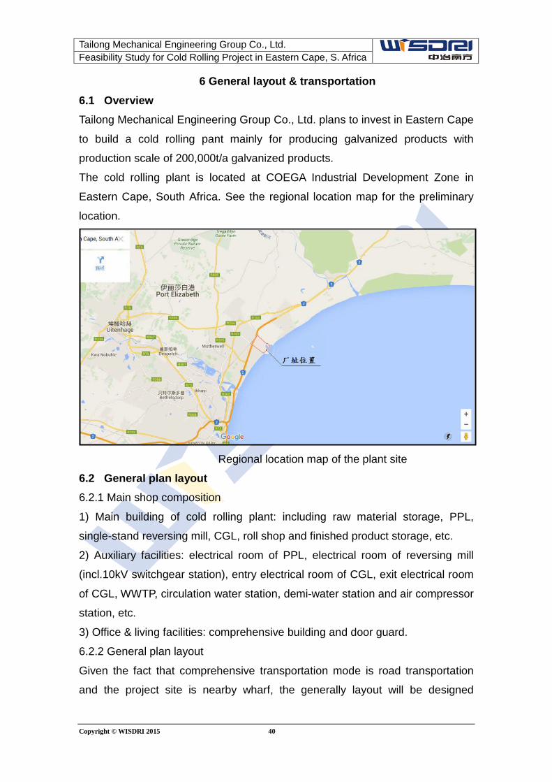
Tailong Mechanical Engineering Group Co., Ltd. Feasibility Study for Cold Rolling Project in Eastern Cape, S. Africa
Copyright © WISDRI 2015 40
6 General layout & transportation 6.1 Overview Tailong Mechanical Engineering Group Co., Ltd. plans to invest in Eastern Cape
to build a cold rolling pant mainly for producing galvanized products with
production scale of 200,000t/a galvanized products.
The cold rolling plant is located at COEGA Industrial Development Zone in
Eastern Cape, South Africa. See the regional location map for the preliminary
location.
Regional location map of the plant site
6.2 General plan layout 6.2.1 Main shop composition
1) Main building of cold rolling plant: including raw material storage, PPL,
single-stand reversing mill, CGL, roll shop and finished product storage, etc.
2) Auxiliary facilities: electrical room of PPL, electrical room of reversing mill
(incl.10kV switchgear station), entry electrical room of CGL, exit electrical room
of CGL, WWTP, circulation water station, demi-water station and air compressor
station, etc.
3) Office & living facilities: comprehensive building and door guard.
6.2.2 General plan layout
Given the fact that comprehensive transportation mode is road transportation
and the project site is nearby wharf, the generally layout will be designed
Tailong Mechanical Engineering Group Co., Ltd. Feasibility Study for Cold Rolling Project in Eastern Cape, S. Africa
Copyright © WISDRI 2015 41
following the principle that main raw material storage and finished product
storage are arranged close to entry/exit for convenient transportation.
The main building of the cold rolling plant is arranged nearby the south of the
battery limit. Electrical room of PL, electrical room of rolling mill (incl. 10kV
switchgear station), entry electrical room of CGL and exit electrical room of CGL
are arranged around the main building. Waste water treatment plant, circulation
water station and air compressor station are arranged one after another from
west to east across the road to the north of the main building. The
comprehensive building is arranged to the east of the main building and to the
south of the entry/exit.
See the general plan layout for detail.
6.3 Vertical arrangement and site drainage Detailed topographic map and relevant information of this area are available,
which will be considered in the next design stage.
6.4 Transportation Road transportation is considered for all the materials of the project. The total
transportation volume is 479,415 t/a, including 230,370t/a input (mainly of hot
rolled coil, HCl, spare parts, new rol, lubricant and cleaning agent, etc.) and
249,045 t/a output (mainly of finished coil/sheet, scrap/crop, worn-out equipment,
waste roll and waste acid, etc.
All the transportation vehicles will be arranged by means of social collaboration.
Urban road is designed for all new roads. Width of the entry/exit road is 7m, and
that of other roads 4m.
6.5 Landscaping Landscaping of the plant will be designed as per the requirements of the owner
for a better environment. Landscaping land rate is considered as 30%.
6.6 Safety and fire fighting 1.80m high metal fence with concrete column is arranged around the plant to
ensure production safety of the plant. 10m wide electrically-operated door is
arranged at the main entry/exit, another 5m wide door is arranged at such
location as for easy connection with the development zone.
Transportation road with width no less than 4m is arranged surrounding the main
building, and it could also be used as fire road.
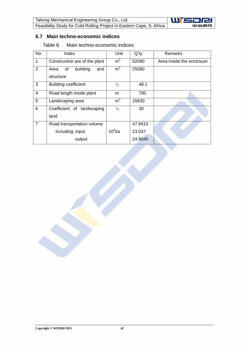
Tailong Mechanical Engineering Group Co., Ltd. Feasibility Study for Cold Rolling Project in Eastern Cape, S. Africa
Copyright © WISDRI 2015 42
6.7 Main techno-economic indices Table 6 Main techno-economic indices
No. Index Unit Q’ty Remarks
1 Construction are of the plant m2 52090 Area inside the enclosure
2 Area of building and
structure
m2 25080
3 Building coefficient % 48.1
4 Road length inside plant m 790
5 Landscaping area m2 15630
6 Coefficient of landscaping
land % 30
7 Road transportation volume
Including: input
output
104t/a
47.9415
23.037
24.9045
Copyright © WISDRI 2015 43
7 Investment estimate 7.1 Project overview A new cold rolling and hot dip galvanizing project is planned to be built in the
Cold Rolling Plant located in Cape Province of South Africa and of which the
annual production capacity is 200,000 t galvanized products.
7.2 Main line composition and auxiliary facilities Push-pull type pickling line 1
Single-stand reversing mill 1
Continuous hot dip galvanizing line 1
Auxiliary facilities include: roll shop, waste water treatment plant, circulation
water station, demineralized water station, air compressor station, 10KV
switchgear station and ARP.
7.3 Investment estimate The investment budget is prepared based on the above mentioned contents.
The static investment of the project is: USD 53.82 million
In which:
Civil work: USD 11.67 million
Equipment and installation work: USD 36.38 million
Other costs: USD 5.77 million
For details, refer to project investment budget list.
7.4 Notes (1) In this investment cost, the subsoil treatment cost is not included.
(2) Other cost and contingency fee of the project construction and budgetary
reserves is considered as 12%.
(3) The investment estimate mentioned herein is the static investment only. It
does not include the interests incurred during the construction period and initial
working capital.
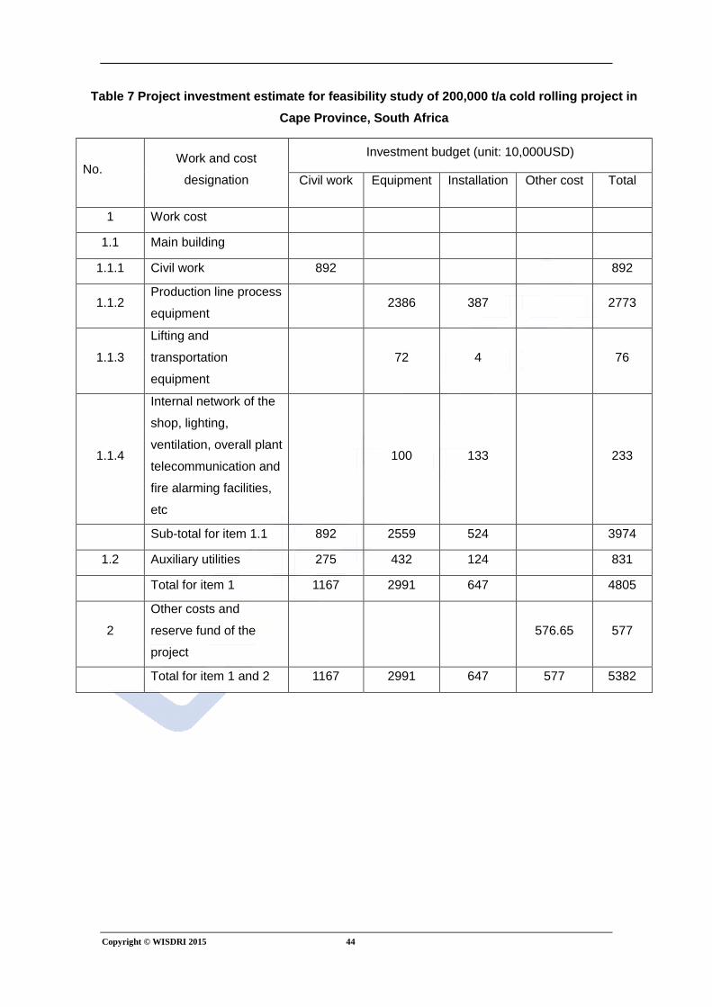
Copyright © WISDRI 2015 44
Table 7 Project investment estimate for feasibility study of 200,000 t/a cold rolling project in Cape Province, South Africa
No. Work and cost
designation
Investment budget (unit: 10,000USD)
Civil work Equipment Installation Other cost Total
1 Work cost
1.1 Main building
1.1.1 Civil work 892 892
1.1.2 Production line process
equipment 2386 387 2773
1.1.3
Lifting and
transportation
equipment
72 4 76
1.1.4
Internal network of the
shop, lighting,
ventilation, overall plant
telecommunication and
fire alarming facilities,
etc
100 133 233
Sub-total for item 1.1 892 2559 524 3974
1.2 Auxiliary utilities 275 432 124 831
Total for item 1 1167 2991 647 4805
2
Other costs and
reserve fund of the
project
576.65 577
Total for item 1 and 2 1167 2991 647 577 5382
Copyright © WISDRI 2015 45
8 Analysis and evaluation of economic benefit
8.1 Overview
Tailong Mechanical Engineering Group Co., Ltd. plans to invest in Eastern
Cape to build a cold rolling pant mainly for producing galvanized products with
production scale of 200,000t/a galvanized products.
The economic benefit analysis of the design is made according to the related
regulations in the Methods and Parameters for Economic Evaluation of
Construction Projects (Rev.3) issued by National Development and Reform
Commission and Ministry of Housing and Urban-Rural Development.
The economic calculation and evaluation contained herein is made on the
project benefit with the assumption that the project is an independent financial
entity. The price calculation made herein does not include taxes
In the calculations, USD will be applied as pricing currency and the prices
involved as RMB and South African Rand will be converted to USD at current
exchange rates.
8.2. Captial demand and capital raising 8.2.1 Total investment of project Total investment of the project is USD 53.82 million and the interest in the
construction period is 3.49 million USD. Refer table 8-1 for the total investment
of project.
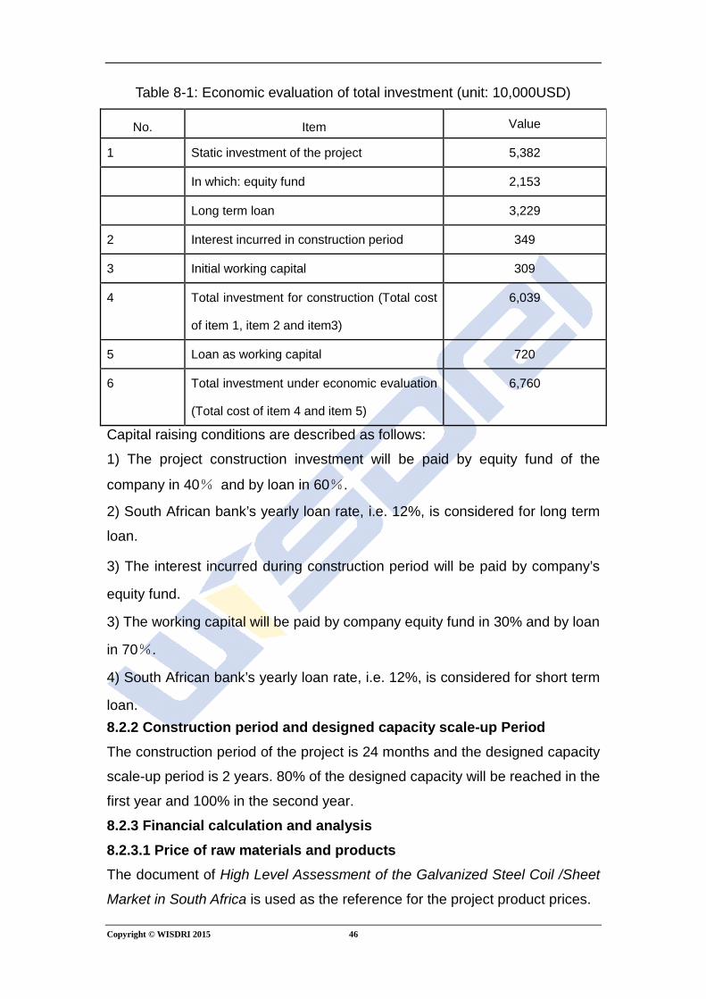
Copyright © WISDRI 2015 46
Table 8-1: Economic evaluation of total investment (unit: 10,000USD)
No. Item Value
1 Static investment of the project 5,382
In which: equity fund 2,153
Long term loan 3,229
2 Interest incurred in construction period 349
3 Initial working capital 309
4 Total investment for construction (Total cost
of item 1, item 2 and item3)
6,039
5 Loan as working capital 720
6 Total investment under economic evaluation
(Total cost of item 4 and item 5)
6,760
Capital raising conditions are described as follows:
1) The project construction investment will be paid by equity fund of the
company in 40% and by loan in 60%.
2) South African bank’s yearly loan rate, i.e. 12%, is considered for long term
loan.
3) The interest incurred during construction period will be paid by company’s
equity fund.
3) The working capital will be paid by company equity fund in 30% and by loan
in 70%.
4) South African bank’s yearly loan rate, i.e. 12%, is considered for short term
loan. 8.2.2 Construction period and designed capacity scale-up Period The construction period of the project is 24 months and the designed capacity
scale-up period is 2 years. 80% of the designed capacity will be reached in the
first year and 100% in the second year.
8.2.3 Financial calculation and analysis 8.2.3.1 Price of raw materials and products The document of High Level Assessment of the Galvanized Steel Coil /Sheet
Market in South Africa is used as the reference for the project product prices.
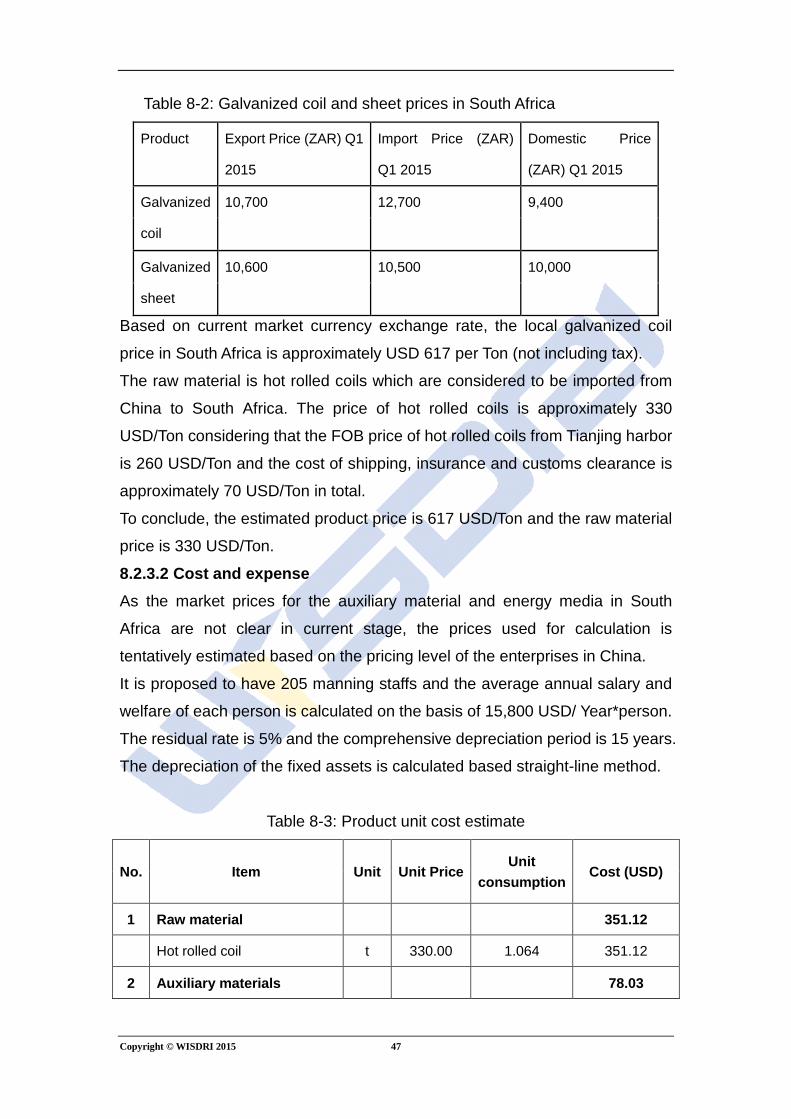
Copyright © WISDRI 2015 47
Table 8-2: Galvanized coil and sheet prices in South Africa
Product Export Price (ZAR) Q1
2015
Import Price (ZAR)
Q1 2015
Domestic Price
(ZAR) Q1 2015
Galvanized
coil
10,700 12,700 9,400
Galvanized
sheet
10,600 10,500 10,000
Based on current market currency exchange rate, the local galvanized coil
price in South Africa is approximately USD 617 per Ton (not including tax).
The raw material is hot rolled coils which are considered to be imported from
China to South Africa. The price of hot rolled coils is approximately 330
USD/Ton considering that the FOB price of hot rolled coils from Tianjing harbor
is 260 USD/Ton and the cost of shipping, insurance and customs clearance is
approximately 70 USD/Ton in total.
To conclude, the estimated product price is 617 USD/Ton and the raw material
price is 330 USD/Ton.
8.2.3.2 Cost and expense As the market prices for the auxiliary material and energy media in South
Africa are not clear in current stage, the prices used for calculation is
tentatively estimated based on the pricing level of the enterprises in China.
It is proposed to have 205 manning staffs and the average annual salary and
welfare of each person is calculated on the basis of 15,800 USD/ Year*person.
The residual rate is 5% and the comprehensive depreciation period is 15 years.
The depreciation of the fixed assets is calculated based straight-line method.
Table 8-3: Product unit cost estimate
No. Item Unit Unit Price Unit
consumption Cost (USD)
1 Raw material
351.12
Hot rolled coil t 330.00 1.064 351.12
2 Auxiliary materials
78.03
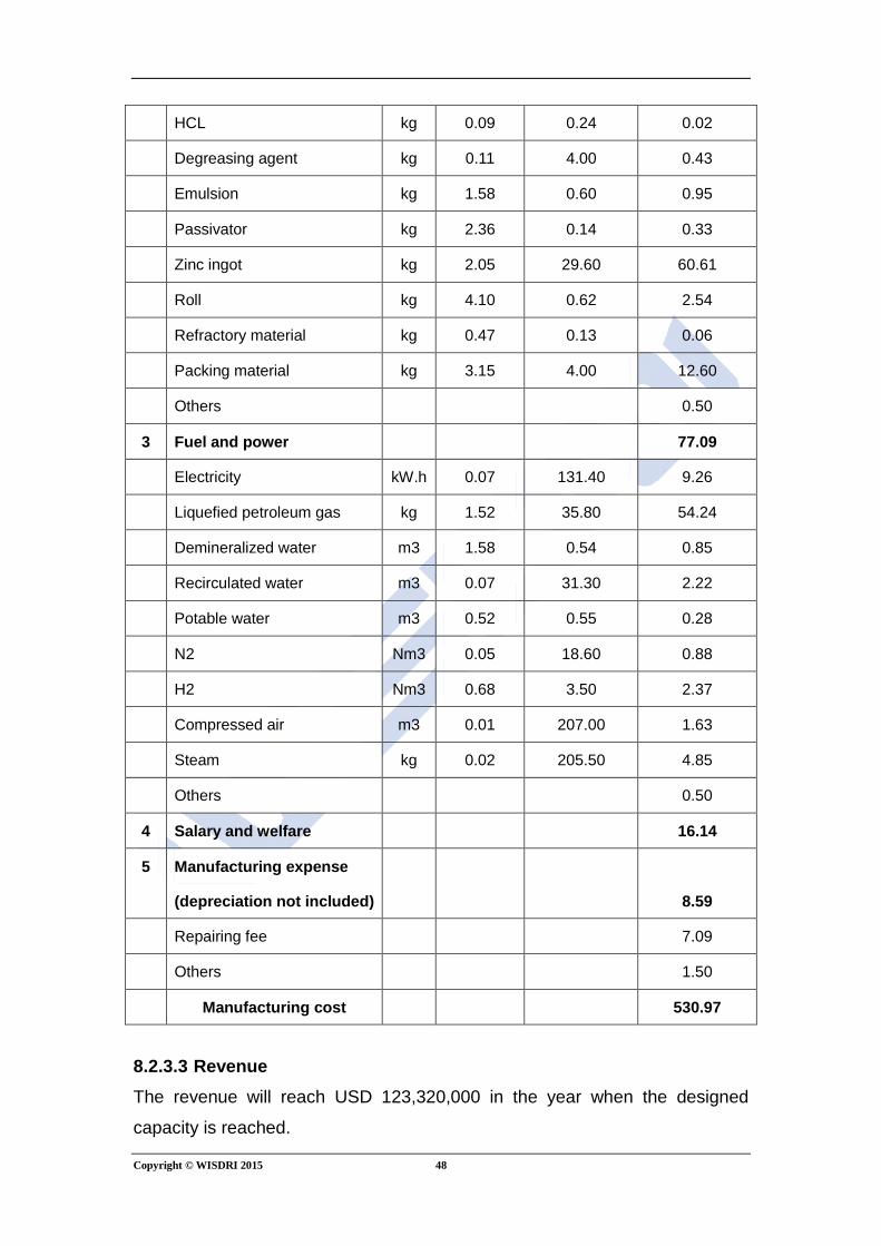
Copyright © WISDRI 2015 48
HCL kg 0.09 0.24 0.02
Degreasing agent kg 0.11 4.00 0.43
Emulsion kg 1.58 0.60 0.95
Passivator kg 2.36 0.14 0.33
Zinc ingot kg 2.05 29.60 60.61
Roll kg 4.10 0.62 2.54
Refractory material kg 0.47 0.13 0.06
Packing material kg 3.15 4.00 12.60
Others
0.50
3 Fuel and power
77.09
Electricity kW.h 0.07 131.40 9.26
Liquefied petroleum gas kg 1.52 35.80 54.24
Demineralized water m3 1.58 0.54 0.85
Recirculated water m3 0.07 31.30 2.22
Potable water m3 0.52 0.55 0.28
N2 Nm3 0.05 18.60 0.88
H2 Nm3 0.68 3.50 2.37
Compressed air m3 0.01 207.00 1.63
Steam kg 0.02 205.50 4.85
Others
0.50
4 Salary and welfare
16.14
5 Manufacturing expense
(depreciation not included)
8.59
Repairing fee
7.09
Others
1.50
Manufacturing cost
530.97
8.2.3.3 Revenue The revenue will reach USD 123,320,000 in the year when the designed
capacity is reached.
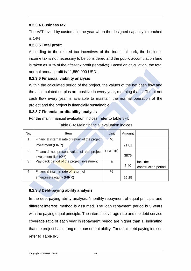
Copyright © WISDRI 2015 49
8.2.3.4 Business tax The VAT levied by customs in the year when the designed capacity is reached
is 14%.
8.2.3.5 Total profit According to the related tax incentives of the industrial park, the business
income tax is not necessary to be considered and the public accumulation fund
is taken as 10% of the after-tax profit (tentative). Based on calculation, the total
normal annual profit is 11,550,000 USD.
8.2.3.6 Financial viability analysis Within the calculated period of the project, the values of the net cash flow and
the accumulated surplus are positive in every year, meaning that sufficient net
cash flow every year is available to maintain the normal operation of the
project and the project is financially sustainable.
8.2.3.7 Financial profitability analysis For the main financial evaluation indices, refer to table 8-4.
Table 8-4: Main financial evaluation indices
No. Item Unit Amount
1 Financial internal rate of return of the project
investment (FIRR)
%
21.81
2 Financial net present value of the project investment (ic=10%)
USD 104 3876
3 Pay-back period of the project investment a 6.40
incl. the construction period
4 Financial internal rate of return of
enterprise’s equity (FIRR)
%
26.25
8.2.3.8 Debt-paying ability analysis
In the debt-paying ability analysis, “monthly repayment of equal principal and
different interest” method is assumed. The loan repayment period is 5 years
with the paying equal principle. The interest coverage rate and the debt service
coverage ratio of each year in repayment period are higher than 1, indicating
that the project has strong reimbursement ability. For detail debt paying indices,
refer to Table 8-5.
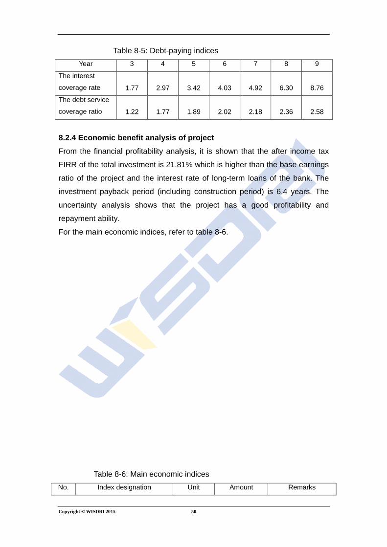
Copyright © WISDRI 2015 50
Table 8-5: Debt-paying indices Year 3 4 5 6 7 8 9
The interest
coverage rate 1.77 2.97 3.42 4.03 4.92 6.30 8.76
The debt service
coverage ratio 1.22 1.77 1.89 2.02 2.18 2.36 2.58
8.2.4 Economic benefit analysis of project From the financial profitability analysis, it is shown that the after income tax
FIRR of the total investment is 21.81% which is higher than the base earnings
ratio of the project and the interest rate of long-term loans of the bank. The
investment payback period (including construction period) is 6.4 years. The
uncertainty analysis shows that the project has a good profitability and
repayment ability.
For the main economic indices, refer to table 8-6.
Table 8-6: Main economic indices No. Index designation Unit Amount Remarks
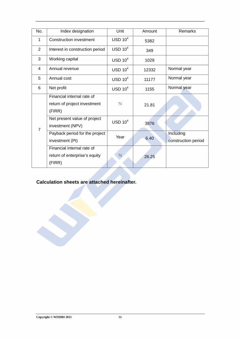
Copyright © WISDRI 2015 51
No. Index designation Unit Amount Remarks
1 Construction investment USD 104 5382
2 Interest in construction period USD 104 349
3 Working capital USD 104 1029
4 Annual revenue USD 104 12332 Normal year
5 Annual cost USD 104 11177 Normal year
6 Net profit USD 104 1155 Normal year
7
Financial internal rate of
return of project investment
(FIRR)
% 21.81
Net present value of project
investment (NPV) USD 104 3876
Payback period for the project
investment (Pt) Year 6.40
Including
construction period
Financial internal rate of
return of enterprise’s equity
(FIRR)
% 26.25
Calculation sheets are attached hereinafter.
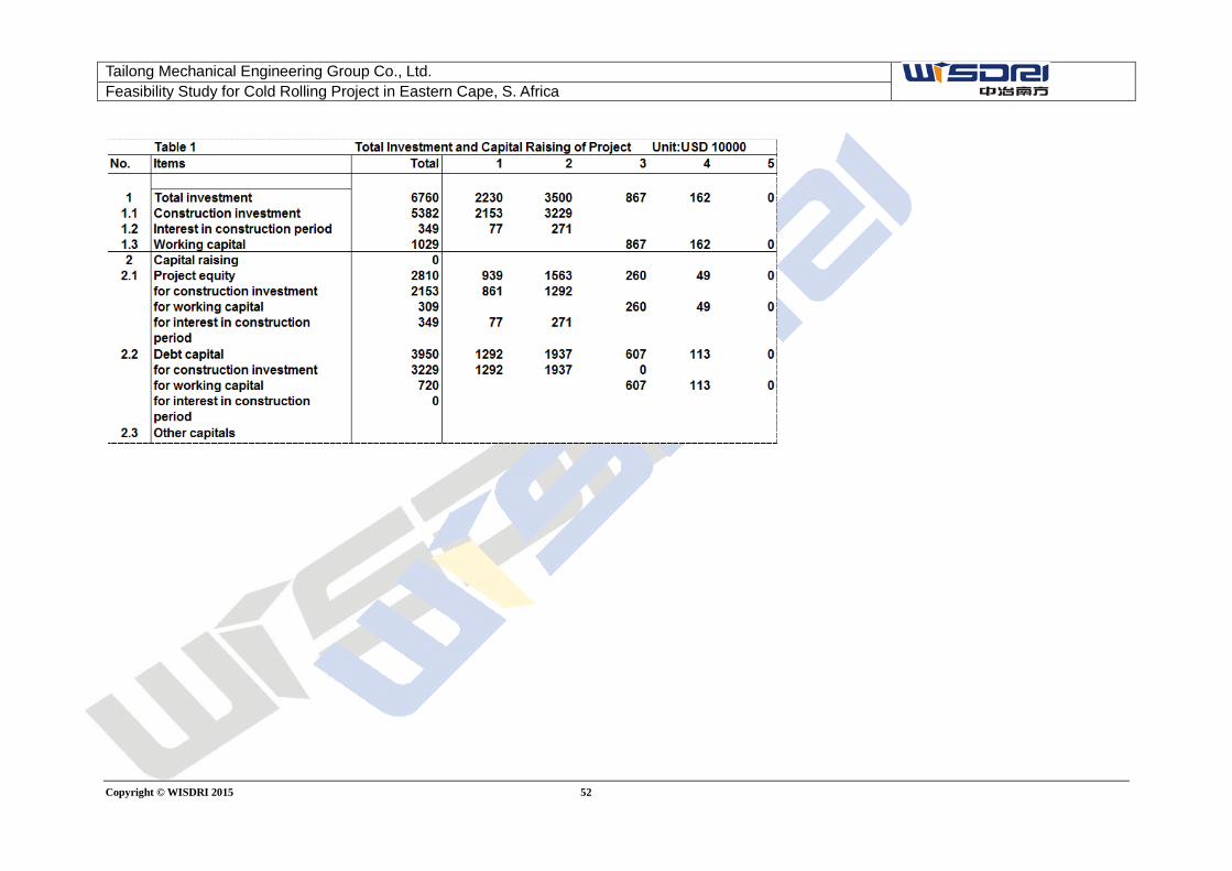
Tailong Mechanical Engineering Group Co., Ltd. Feasibility Study for Cold Rolling Project in Eastern Cape, S. Africa
Copyright © WISDRI 2015 52

Tailong Mechanical Engineering Group Co., Ltd. Feasibility Study for Cold Rolling Project in Eastern Cape, S. Africa
Copyright © WISDRI 2015 53
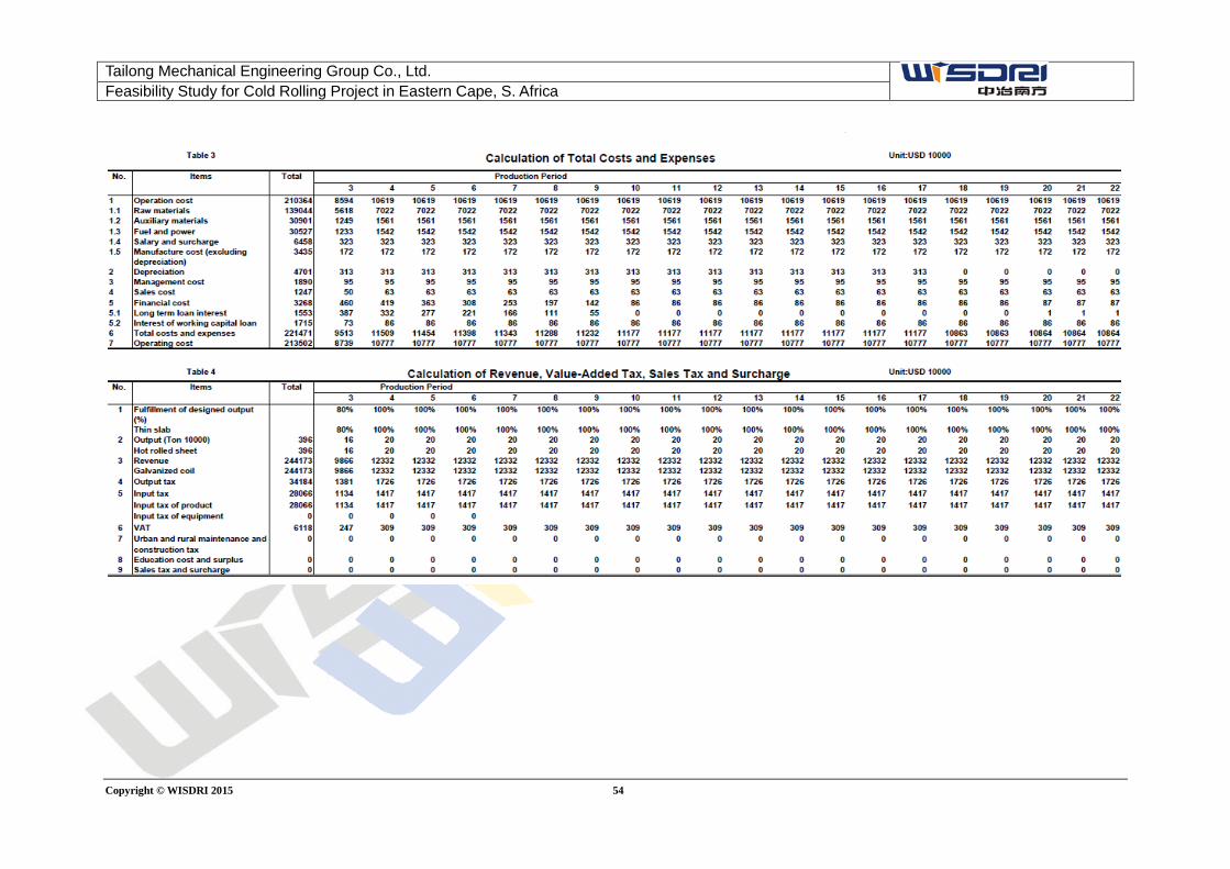
Tailong Mechanical Engineering Group Co., Ltd. Feasibility Study for Cold Rolling Project in Eastern Cape, S. Africa
Copyright © WISDRI 2015 54
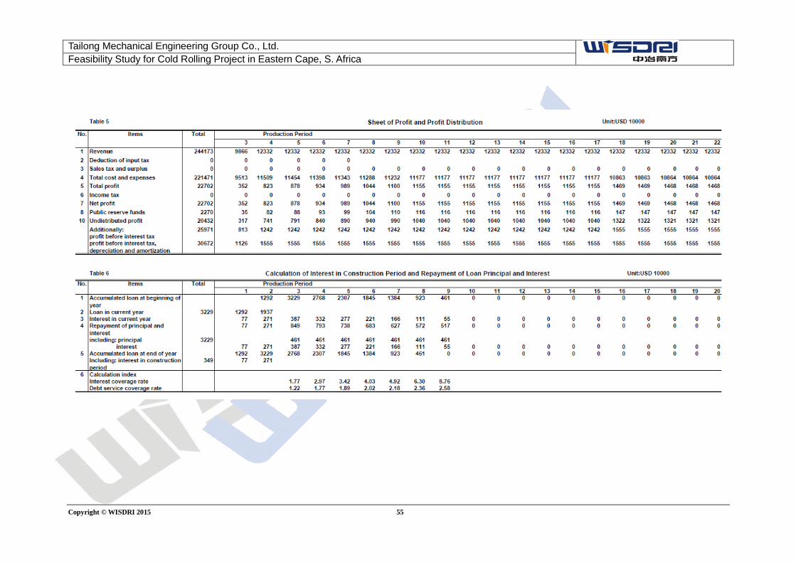
Tailong Mechanical Engineering Group Co., Ltd. Feasibility Study for Cold Rolling Project in Eastern Cape, S. Africa
Copyright © WISDRI 2015 55
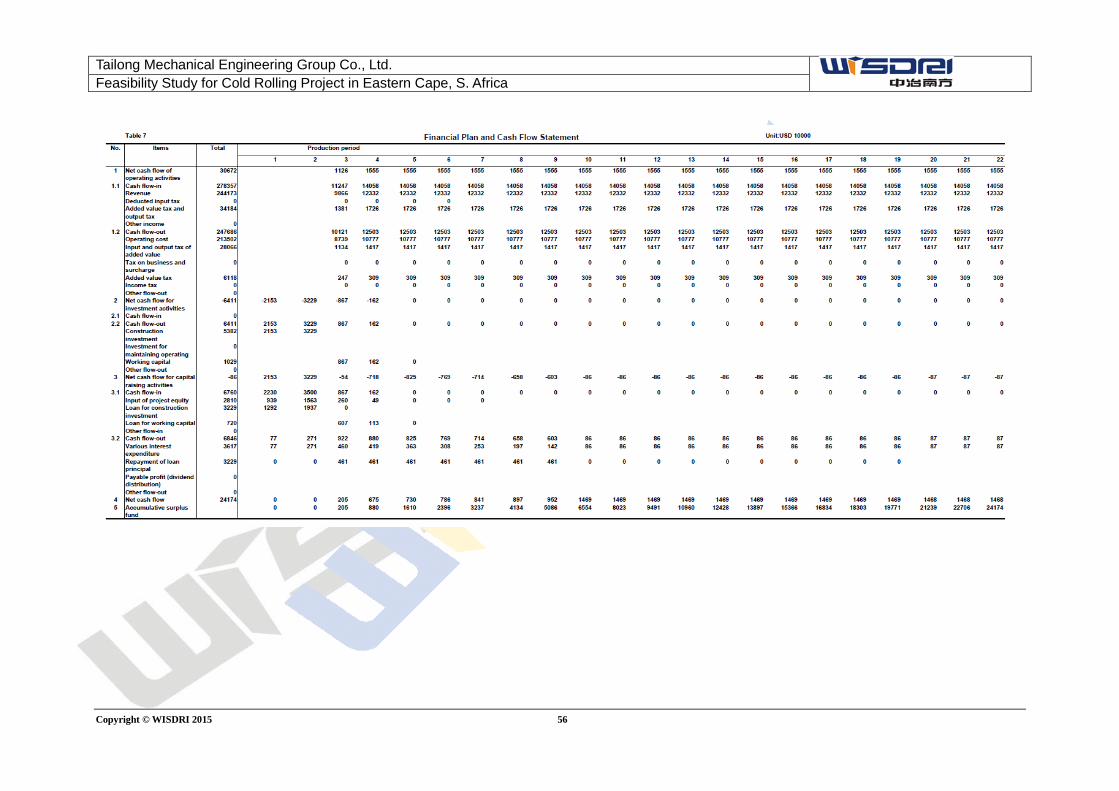
Tailong Mechanical Engineering Group Co., Ltd. Feasibility Study for Cold Rolling Project in Eastern Cape, S. Africa
Copyright © WISDRI 2015 56
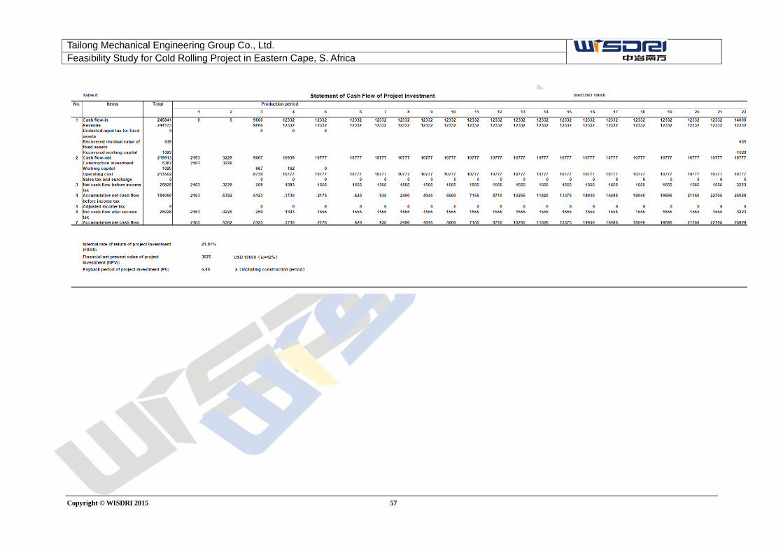
Tailong Mechanical Engineering Group Co., Ltd. Feasibility Study for Cold Rolling Project in Eastern Cape, S. Africa
Copyright © WISDRI 2015 57
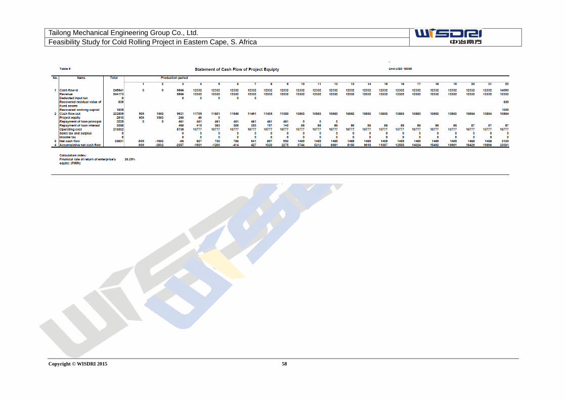
Tailong Mechanical Engineering Group Co., Ltd. Feasibility Study for Cold Rolling Project in Eastern Cape, S. Africa
Copyright © WISDRI 2015 58
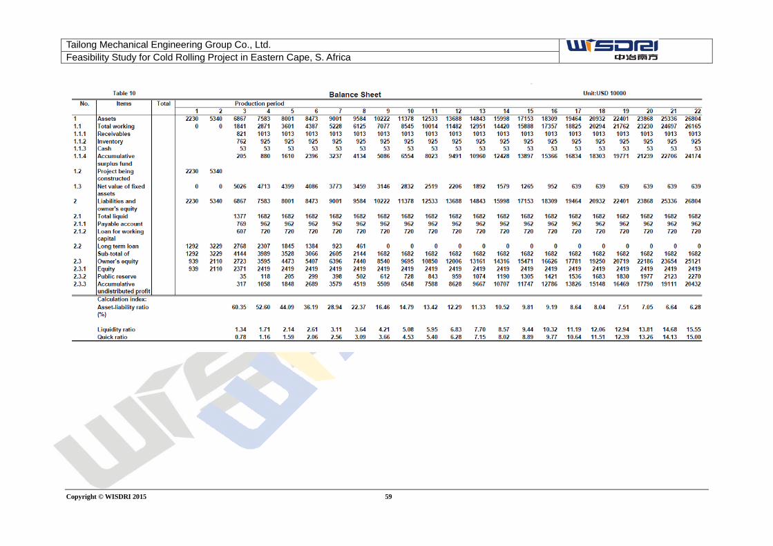
Tailong Mechanical Engineering Group Co., Ltd. Feasibility Study for Cold Rolling Project in Eastern Cape, S. Africa
Copyright © WISDRI 2015 59
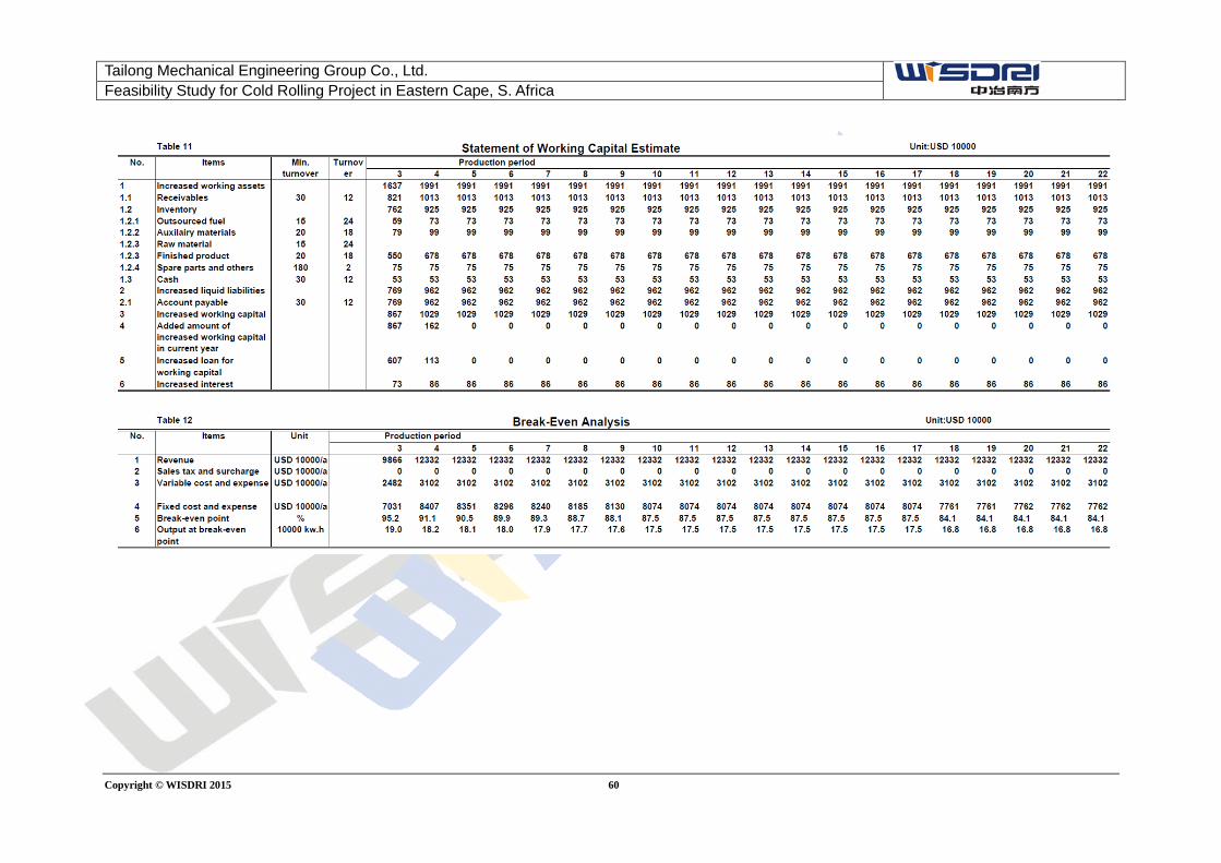
Tailong Mechanical Engineering Group Co., Ltd. Feasibility Study for Cold Rolling Project in Eastern Cape, S. Africa
Copyright © WISDRI 2015 60
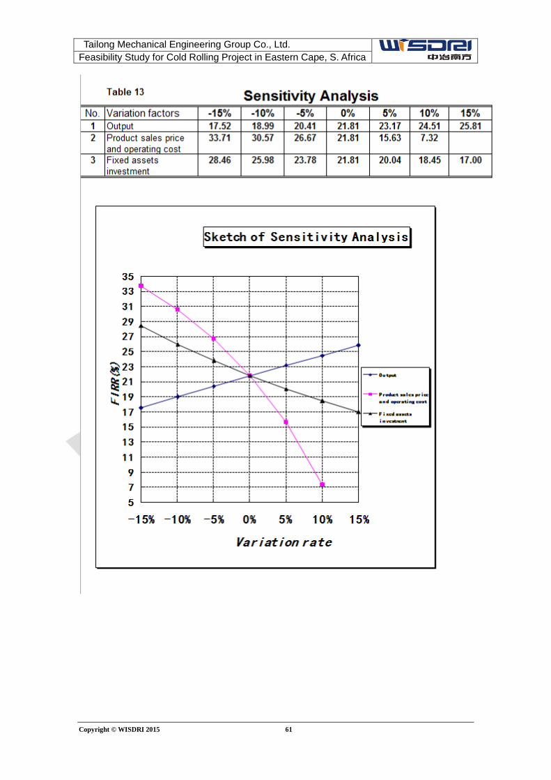
Tailong Mechanical Engineering Group Co., Ltd. Feasibility Study for Cold Rolling Project in Eastern Cape, S. Africa
Copyright © WISDRI 2015 61