Embed Size (px)
Citation preview
w
FEED AND BIOFUEL
CONVEYING EQUIPMENTSCREW CONVEYOR TYPE SC DOUBLE
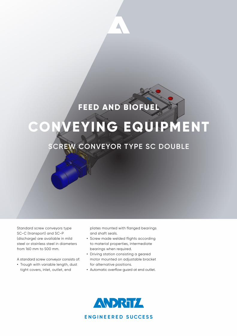
Standard screw conveyors type SC-C (transport) and SC-P (discharge) are available in mild steel or stainless steel in diameters from 160 mm to 500 mm.
A standard screw conveyor consists of:• Trough with variable length, dust
tight covers, inlet, outlet, end
plates mounted with flanged bearings and shaft seals.
• Screw made welded flights according to material properties, intermediate bearings when required.
• Driving station consisting a geared motor mounted on adjustable bracket for alternative positions.
• Automatic overflow guard at end outlet.
All data, information, statements, photographs and graphic illustrations in this leaflet are without any obligation and raise no liabilities to or form part of any sales contracts of ANDRITZ AG or any affiliates for equipment and/or systems referred to herein. © ANDRITZ AG 2018. All rights reserved. No part of this copyrighted work may be reproduced, modified or distributed in any form or by any means, or stored in any database or retrieval system, without the prior written permission of ANDRITZ AG or its affiliates. Any such unauthorized use for any purpose is a violation of the relevant copyright laws. ANDRITZ AG, Stattegger Strasse 18, 8045 Graz, Austria.
A
A
At A1=30° Trough angle
At A1=0° Trough angle
IL-Inlet Left IT-Inlet Top
(Not Available for few Kw Gear Motors Check With
Engineering Dept.)
OR-Outlet Right OL-Outlet Left OT-Outlet Top
L1
Size 160 200 250 315 350 400 500Ø 160 200 250 315 350 400 500C1 *Customer Spec. *Customer Spec. *Customer Spec. *Customer Spec. *Customer Spec. *Customer Spec. *Customer Spec.L1 *Customer Spec. *Customer Spec. *Customer Spec. *Customer Spec. *Customer Spec. *Customer Spec. *Customer Spec.A1 0° or 30° 0° or 30° 0° or 30° 0° or 30° 0° or 30° 0° or 30° 0° or 30°CD 180 222 272 340 376 428 535B 432 514 614 735 824 926 1140b 575 687 824 1014 1113 1251 1546C 356 438 538 675 746 848 1060c 499 611 748 936 1035 1173 1466D 100 120 145 180 200 224 280E 3 3 3 4 4 4 5F 160 200 250 315 350 400 500f 326 406 506 638 708 808 1010G 230 270 320 386 428 479 586g 396 476 576 710 786 887 1096H 2 X 10² 2 X 122 2 X 147 3 X 120 3 X 134 3 X 151 4 X 140h 3 X 123.33 3 X 150 4 X 137.5 5 X 136.8 6 X 126.67 7 X 123 8 X 133.75I 140 160 185 220 235 260 320J 3 X 134 3 X 161.33 4 X 146 5 X 144.6 6 X 132.33 6X 149.33 8 X 138.75j 4 X 136.25 5 X 131.4 6 X 132.33 7 X 140.57 8 X 135.38 9 X 135.67 11 X 137.82
At A1=30° Trough angle
At A1=0° Trough angle
At Inlet:
At Outlet:
IR-Inlet Right
(Standard)
*Contact Engineering for Details.**Dimension depends on L1.
Inlet
Outlet
Outlet Details:
Section A-A:Screw conveyors:Double Screw Series
Inlet Details:
15
Gear Motor Location Options:
*
SC - 160 - D - C - 2000 - 1000 - 30 - 1 - 1 - IR - D1 2 3 4 5 6 7 8 9 10
Model Desc. Sample:
Basic Series:
SC-Screw Conveyor
1
2 Screw Size:
160 - 160 Dia Screw200 - 200 Dia Screw250 - 250 Dia Screw315 - 315 Dia Screw350 - 350 Dia Screw400 - 400 Dia Screw500 - 500 Dia Screw
Number of Screw:
D-Double Screw
3
Center Dist. Inlet & Outlet (C1):
Refer Sketch & Table for Details
5
Length of inlet (L1):
Refer Sketch & Table for Details
6
Trough Angle (A1):
0° or 30° As Standard Non-Standard also avialable up on Request(Inlet Flange Dim need to change based on Trough Angle)
7
Body Material:
1 - Normal Steel (S235)2 - Stainless Steel (SS304)3 - Stainless Steel (SS316)
8
Shaft Material:
1 - Normal Steel (S235)2 - Stainless Steel (SS304)3 - Stainless Steel (SS316)
9
Gear Motor Location:
IR - Inlet Right (Standard)IL - Inlet LeftIT - Inlet Top (Not always Available)
OR - Outlet RightOL - Outlet LeftOT - Outlet Top
10
Screw Pitch: C-Constant PitchP-Progressive Pitch
4Gearmotor at inlet Right
11
Optional Features: This section can have multiple options
D- Dosing (Extra Flight in Outlet)NF - No Outlet FlangeCFI-Counter Flange InletCFO-Counter Flange OutletAF-Air Flap Near OutletOF-Overflow Flap
11
**
j
15 12
L1+80
L1
c b
C1
G
F
h gf
CD
c
b
I
D
CD
I
D
E
E
B
C
12
1515
J
L1
L1+80
**
BC
12
Overflow Control Unit
H
1313
A1
Ø
Ø
A
A
At A1=30° Trough angle
At A1=0° Trough angle
IL-Inlet Left IT-Inlet Top
(Not Available for few Kw Gear Motors Check With
Engineering Dept.)
OR-Outlet Right OL-Outlet Left OT-Outlet Top
L1
Size 160 200 250 315 350 400 500Ø 160 200 250 315 350 400 500C1 *Customer Spec. *Customer Spec. *Customer Spec. *Customer Spec. *Customer Spec. *Customer Spec. *Customer Spec.L1 *Customer Spec. *Customer Spec. *Customer Spec. *Customer Spec. *Customer Spec. *Customer Spec. *Customer Spec.A1 0° or 30° 0° or 30° 0° or 30° 0° or 30° 0° or 30° 0° or 30° 0° or 30°CD 180 222 272 340 376 428 535B 432 514 614 735 824 926 1140b 575 687 824 1014 1113 1251 1546C 356 438 538 675 746 848 1060c 499 611 748 936 1035 1173 1466D 100 120 145 180 200 224 280E 3 3 3 4 4 4 5F 160 200 250 315 350 400 500f 326 406 506 638 708 808 1010G 230 270 320 386 428 479 586g 396 476 576 710 786 887 1096H 2 X 10² 2 X 122 2 X 147 3 X 120 3 X 134 3 X 151 4 X 140h 3 X 123.33 3 X 150 4 X 137.5 5 X 136.8 6 X 126.67 7 X 123 8 X 133.75I 140 160 185 220 235 260 320J 3 X 134 3 X 161.33 4 X 146 5 X 144.6 6 X 132.33 6X 149.33 8 X 138.75j 4 X 136.25 5 X 131.4 6 X 132.33 7 X 140.57 8 X 135.38 9 X 135.67 11 X 137.82
At A1=30° Trough angle
At A1=0° Trough angle
At Inlet:
At Outlet:
IR-Inlet Right
(Standard)
*Contact Engineering for Details.**Dimension depends on L1.
Inlet
Outlet
Outlet Details:
Section A-A:Screw conveyors:Double Screw Series
Inlet Details:
15
Gear Motor Location Options:
*
SC - 160 - D - C - 2000 - 1000 - 30 - 1 - 1 - IR - D1 2 3 4 5 6 7 8 9 10
Model Desc. Sample:
Basic Series:
SC-Screw Conveyor
1
2 Screw Size:
160 - 160 Dia Screw200 - 200 Dia Screw250 - 250 Dia Screw315 - 315 Dia Screw350 - 350 Dia Screw400 - 400 Dia Screw500 - 500 Dia Screw
Number of Screw:
D-Double Screw
3
Center Dist. Inlet & Outlet (C1):
Refer Sketch & Table for Details
5
Length of inlet (L1):
Refer Sketch & Table for Details
6
Trough Angle (A1):
0° or 30° As Standard Non-Standard also avialable up on Request(Inlet Flange Dim need to change based on Trough Angle)
7
Body Material:
1 - Normal Steel (S235)2 - Stainless Steel (SS304)3 - Stainless Steel (SS316)
8
Shaft Material:
1 - Normal Steel (S235)2 - Stainless Steel (SS304)3 - Stainless Steel (SS316)
9
Gear Motor Location:
IR - Inlet Right (Standard)IL - Inlet LeftIT - Inlet Top (Not always Available)
OR - Outlet RightOL - Outlet LeftOT - Outlet Top
10
Screw Pitch: C-Constant PitchP-Progressive Pitch
4Gearmotor at inlet Right
11
Optional Features: This section can have multiple options
D- Dosing (Extra Flight in Outlet)NF - No Outlet FlangeCFI-Counter Flange InletCFO-Counter Flange OutletAF-Air Flap Near OutletOF-Overflow Flap
11
**
j
15 12
L1+80
L1
c b
C1
G
F
h gf
CD
c
b
I
D
CD
I
D
E
E
B
C
12
1515
J
L1
L1+80
**
BC
12
Overflow Control Unit
H
1313
A1
Ø
Ø
Dimensions in mm
1188 GB
B 0
718
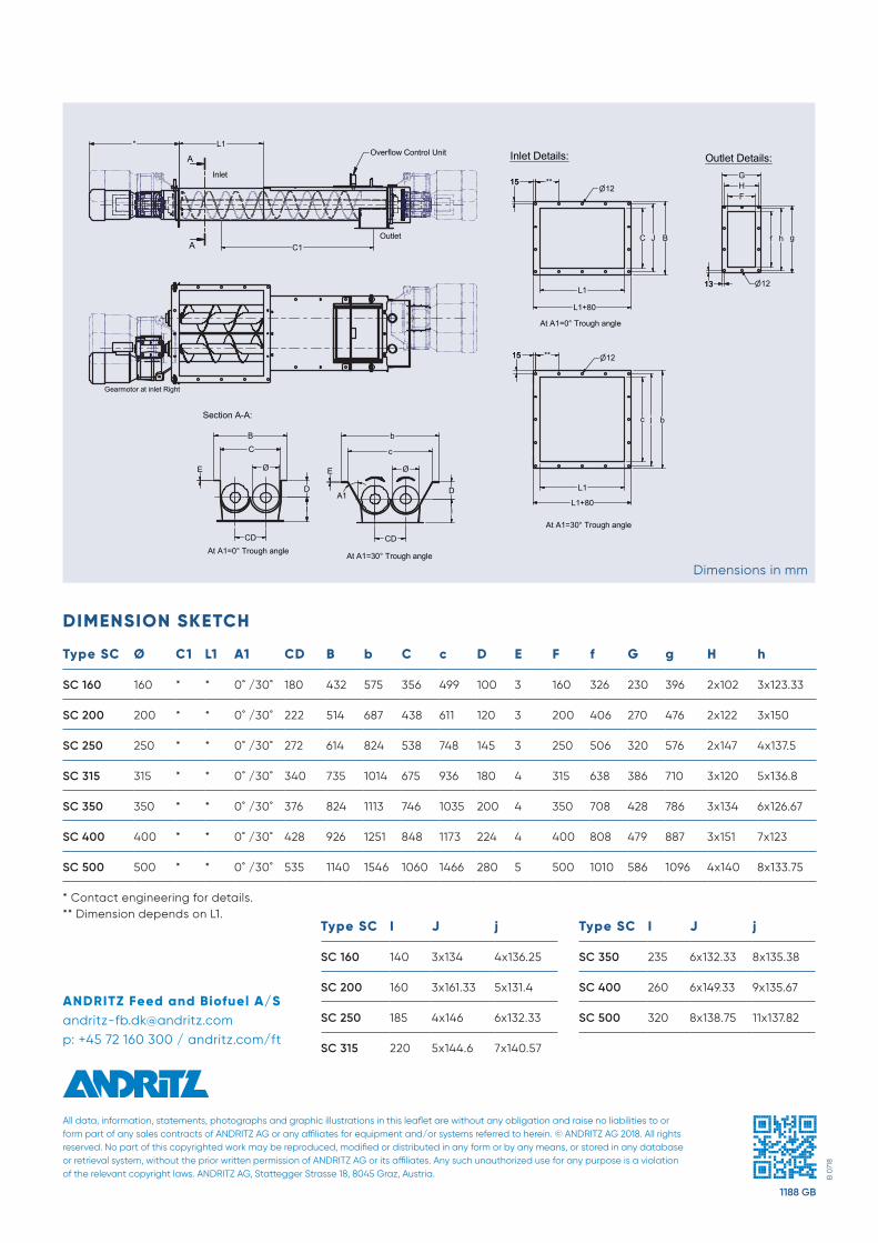
DIMENSION SKETCH
Type SC Ø C1 L1 A1 CD B b C c D E F f G g H h
SC 160 160 * * 0˚ /30˚ 180 432 575 356 499 100 3 160 326 230 396 2x10² 3x123.33
SC 200 200 * * 0˚ /30˚ 222 514 687 438 611 120 3 200 406 270 476 2x122 3x150
SC 250 250 * * 0˚ /30˚ 272 614 824 538 748 145 3 250 506 320 576 2x147 4x137.5
SC 315 315 * * 0˚ /30˚ 340 735 1014 675 936 180 4 315 638 386 710 3x120 5x136.8
SC 350 350 * * 0˚ /30˚ 376 824 1113 746 1035 200 4 350 708 428 786 3x134 6x126.67
SC 400 400 * * 0˚ /30˚ 428 926 1251 848 1173 224 4 400 808 479 887 3x151 7x123
SC 500 500 * * 0˚ /30˚ 535 1140 1546 1060 1466 280 5 500 1010 586 1096 4x140 8x133.75
* Contact engineering for details. ** Dimension depends on L1.
Type SC I J j
SC 160 140 3x134 4x136.25
SC 200 160 3x161.33 5x131.4
SC 250 185 4x146 6x132.33
SC 315 220 5x144.6 7x140.57
Type SC I J j
SC 350 235 6x132.33 8x135.38
SC 400 260 6x149.33 9x135.67
SC 500 320 8x138.75 11x137.82ANDRITZ Feed and Biofuel A/[email protected]: +45 72 160 300 / andritz.com/ft