Embed Size (px)
Citation preview

Fibre cement slates fixing guide 53
Fibre cement slatesFixing guide
CI/SfB (4-) Rf9 March 2015
Call 01283 722588Email [email protected] visit www.marleyeternit.co.uk
Marley Eternit Lichfield Road Branston Burton upon Trent DE14 3HD
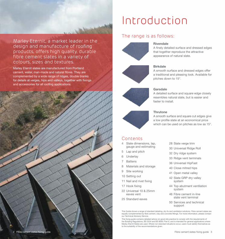
The range is as follows:RivendaleA finely detailed surface and dressed edgesthat together reproduce the attractiveappearance of natural slate.
BirkdaleA smooth surface and dressed edges offera traditional and pleasing look. Available forpitches down to 15°.
GarsdaleA detailed surface and square edge closelyresembles natural slate, but is easier andfaster to install.
ThrutoneA smooth surface and square cut edges givea low profile slate at an economical pricewhich can be used on pitches as low as 15°.
2 Fibre cement slates fixing guide Fibre cement slates fixing guide 3
Contents 4 Slate dimensions, lap,
gauge and estimating
5 Lap and pitch
6 Underlay
7 Battens
8 Materials and storage
9 Site working
10 Setting out
11 Nail and rivet fixing
17 Hook fixing
22 Universal 10 & 25mmeaves vent
25 Standard eaves
28 Slate verge trim
30 Universal Ridge Roll
32 Dry ridge system
33 Ridge vent terminals
36 Universal HipFast
40 Close mitred hips
41 Open metal valley
42 Slate GRP dry valley system
44 Top abutment ventilation system
46 Fibre cement in-line slate vent terminal
50 Services and technical support
This Guide shows a range of standard detailing, dry fix and ventilation solutions. Fibre cement slates areequally complemented by fibre cement, clay and concrete fittings. For more information, please contactour Technical Advisory Service.
This fixing guide contains detailed advice on good site practice to comply with the requirements of the Building Regulations, BS 5534 and BS 8000: Part 6, and is intended for general applications whereMarley Eternit Slates are used. Where non-standard situations occur, users must satisfy themselves asto the suitability of the recommendations given.
Introduction
Marley Eternit, a market leader in thedesign and manufacture of roofingproducts, offers high quality, durablefibre cement slates in a variety ofcolours, sizes and textures. Marley Eternit slates are manufactured from Portland cement, water, man-made and natural fibres. They arecomplemented by a wide range of ridges, double blanks for details at verges, hips and valleys, together with fixings and accessories for all roofing applications.
4 Fibre cement slates fixing guide Fibre cement slates fixing guide 5
Slate dimensions,lap, gauge andestimating
Lap treatments
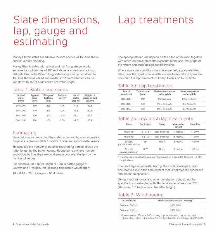
The appropriate lap will depend on the pitch of the roof, togetherwith other factors such as the exposure of the site, the length of the rafters and other design considerations.
Where abnormal conditions may be expected, e.g. on elevatedsites, near the coast or in localities where heavy falls of snow arecommon, the lap treatments will vary. Refer also to BS 5534.
Table 2a: Lap treatments Size of Typical laps Moderate exposure Severe exposure slate (mm) (mm) rafter pitch rafter pitch
600 x 300 110 20˚ and over 22.5˚ and over
600 x 300 100 22.5˚ and over 25˚ and over
500 x 250 100 22.5˚ and over 25˚ and over
Table 2b: Low pitch lap treatments Slate Roof pitch Fixing Max. rafter Headlap length
Thrutone* 15 - 17.5º Nail and rivet 4 metres 110mm
Thrutone* 17.5 - 20° Nail and rivet 6 metres 110mm
Birkdale 15º Hook 6 metres 150mm(moderate exposure)
Birkdale 17.5º Hook 9 metres 150mm (severe exposure)
* Roof window penetrations are not recommended in low pitch Thrutone (15-20°)applications.
The discharge of rainwater from gutters and downpipes, from one roof to a low pitch fibre cement roof is not recommended andshould not be specified.
Skylight roof windows and other penetrations should not bespecified or constructed with Thrutone slates at less than 20° (Thrutone, 15° have a max. 4m rafter length).
Table 3: Windloading Size of slate Maximum wind suction loading**
600mm x 300mm 2000 N/m2
500mm x 250mm 2500 N/m2
** When using two 30mm x 2.65mm long copper nails with copper disc rivet(19mm x 2mm stem, 19mm dia x 0.5mm thick base) in accordance with BS 5534.
Marley Eternit slates are suitable for roof pitches of 15° and aboveand for vertical cladding.
Marley Eternit slates with a rivet and nail fixing are generallysuitable for roof pitches of 20° and above and vertical cladding.Birkdale fixed with 150mm long slate hooks can be laid down to15° and Thrutone nailed and riveted at 110mm headlap can be laid down to 15° at a maximum 4m rafter length.
Table 1: Slate dimensionsSize of Typical Gauge of Battens No. of Weight ofslate laps battens per m2 slates slates as laid(mm) (mm) (mm) (per m2) (kg/m2)
600 x 300 150 225 4.45 14.8 22.8
600 x 300 110 245 4.08 13.6 20.9
600 x 300 100 250 4.00 13.4 20.4
500 x 250 100 200 5.00 19.6 20.9
EstimatingBasic information regarding the stated sizes and laps for estimatingpurposes is given in Table 1, above. These are approximate values.
To calculate the number of doubles required for verges, divide therafter length by the batten gauge. Round up to a whole numberand divide by 2 as they are on alternate courses. Multiply by thenumber of verges.
For example, for a rafter length of 10m, a batten gauge of 250mm and 4 verges, the following calculation would apply.
10 ÷ 0.25 = 20 x 4 verges = 80 doubles
Fibre cement slates fixing guide 76 Fibre cement slates fixing guide
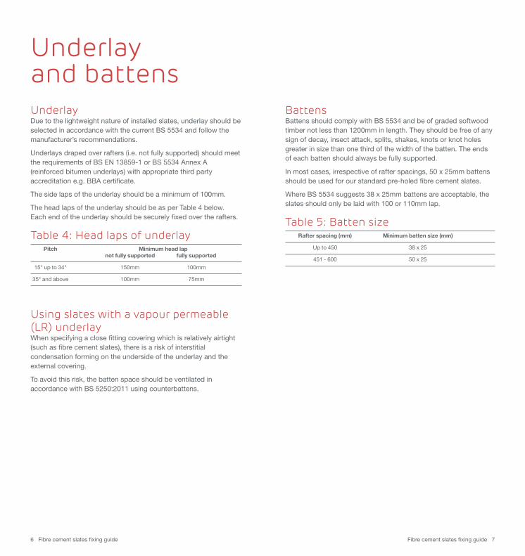
Underlay and battensUnderlayDue to the lightweight nature of installed slates, underlay should beselected in accordance with the current BS 5534 and follow themanufacturer’s recommendations.
Underlays draped over rafters (i.e. not fully supported) should meetthe requirements of BS EN 13859-1 or BS 5534 Annex A(reinforced bitumen underlays) with appropriate third partyaccreditation e.g. BBA certificate.
The side laps of the underlay should be a minimum of 100mm.
The head laps of the underlay should be as per Table 4 below.Each end of the underlay should be securely fixed over the rafters.
Table 4: Head laps of underlay Pitch Minimum head lap not fully supported fully supported
15° up to 34° 150mm 100mm
35° and above 100mm 75mm
Using slates with a vapour permeable (LR) underlay When specifying a close fitting covering which is relatively airtight(such as fibre cement slates), there is a risk of interstitialcondensation forming on the underside of the underlay and theexternal covering.
To avoid this risk, the batten space should be ventilated inaccordance with BS 5250:2011 using counterbattens.
BattensBattens should comply with BS 5534 and be of graded softwoodtimber not less than 1200mm in length. They should be free of anysign of decay, insect attack, splits, shakes, knots or knot holesgreater in size than one third of the width of the batten. The endsof each batten should always be fully supported.
In most cases, irrespective of rafter spacings, 50 x 25mm battensshould be used for our standard pre-holed fibre cement slates.
Where BS 5534 suggests 38 x 25mm battens are acceptable, theslates should only be laid with 100 or 110mm lap.
Table 5: Batten sizeRafter spacing (mm) Minimum batten size (mm)
Up to 450 38 x 25
451 - 600 50 x 25
Fibre cement slates fixing guide 98 Fibre cement slates fixing guide
Slates should be scored using a scribing tool and snapped over astraight edge.
Slates can be cut using a normal handsaw/hacksaw with teeth of3mm - 3.5mm pitch, preferably wide set. Saws should always beused to start off when cutting acute angles.
Marley Eternit slates may be cut with a reciprocating saw. The useof angle grinders is not recommended for cutting as these toolscan raise nuisance dust levels and are unnecessary.
Additional fixing holes should be drilled using a 4.0mm dia.standard drill bit. Fixing holes must not be punched.
After cutting or drilling, remove cutting dust from the slate to avoidsubsequent staining.
Marley Eternit slates should not be cut with a slater’s axe.
Note: Consideration should be given to sealing any cut edges to prevent potentialefflorescence staining.
As this product is made mainly of natural raw materials, it cancontain traces of quartz.
Mechanical machining (cutting, sanding, drilling) of this productcan release dust which may contain quartz particles. We thereforerequest that the following general and personal protectionmeasures are always used:
• Avoid the generation of airborne dust by using tools with built-in dust extraction.
• Ensure that adequate ventilation is provided at the work place.
• Avoid contact with eyes and skin and avoid inhalation of dust by wearing appropriate personal protection equipment (safety goggles, protective clothing and a dust mask of at least type P2).
For further information, please contact the Marley Eternit TechnicalAdvisory Service on 01283 722588.
Nails, rivets, screwsSlate nails: nails for fixing slates should be 2.65mm (12 swg)Marley Eternit Slates jagged copper nails, 30mm long.
Batten nails: nails for fixing battens should be in accordance with BS 5534.
Slate rivets: copper disc rivet, 19mm x 2mm stem, 19mm dia. x 0.5mm thick base.
Screws: 60mm x 6.3mm self-sealing, nylon headed screws,longer screws may be required for different applications (screwsonly used with fibre cement ridges).
LeadWhen lead is used for flashings and soakers, lead oxide carried inthe water run-off is likely to stain the slates. To avoid this, apply‘Patination Oil’ to the lead immediately after it is fixed.
Information on the supply of patination oil can be obtained fromBritish Lead, Telephone 01707 324595.
For details of all leadwork, flashings and ‘Patination Oil’ pleaseconsult the Lead Sheet Association, Telephone 01622 872432.
Storage of slatesSlates should not be allowed to become wet when in packs orbanded together, as efflorescence and staining can occur.
Storage inside a building or similar shelter: the polythene hoodscovering the slates should remain as a temporary protection to theslates, provided no water vapour can enter from below the packs.
Storage outside: remove the polythene hoods and stack the slatesin bundles off the ground and cover with a good tarpaulin allowingclearance between the tarpaulin and the slates. This will allow freeair movement and help prevent condensation forming within thepack (which could cause efflorescence).
If the slates are to be stored outside for a very short period of time,then the sides of the hood should be split open before coveringwith a tarpaulin to reduce the risk of condensation in the packs.
On larger contracts, it is better to avoid storing too many packs on-site and to schedule deliveries of slates as they are required.
Slates should be fixed in accordance with BS 5534 ‘Code ofpractice for slating and tiling (including shingles)’ and BS 8000-6‘Workmanship on building sites ‘Code of practice for slating andtiling of roofs and claddings’.
Site working Materials and storage
Fibre cement slates fixing guide 1110 Fibre cement slates fixing guide
Setting out
Setting out of battensRoofs should be set out with battens to the appropriate gauge. Select the appropriate gauge for the slate size by using the formula:
gauge = length of slate - lap required
2
Allow the eaves slates to overhang into the gutter by approx.50mm. The verge overhang should be restricted to a maximumof 50mm.
Care must be taken when setting out to avoid the need forrectangular cut slates less than half the width of the slate to beused, as it may be difficult to fix. Wherever possible, use full slatesor slate-and-a-half slates.
A vertical or raking batten is advisable at the verge and atintersections.
Introduction• All slates should be fixed in accordance with BS 5534 and
BS 8000-6
• Slates should be laid broken bond using slate-and-a-half width slates in alternate courses formed from double width slates at verges, hips, valleys and abutments.
• Maximum 5mm gap between adjacent slates for disc rivet shank, 3-4mm is optimum.
• Nail slates firmly but do not drive nails too tight to the surface of the slate
• For full details of headlap and rafter lengths suitable for hook fixing, please refer to table 2 on page 5.
Fixing methodEnsure each slate is centre nailed with 2 No. 30mm x 2.65mmjagged copper nails and restrained at the bottom edge with acopper disc rivet (19mm x 2mm stem, 19mm dia. x 0.5mm thickbase). Double or slate-and-a-half slates must be fixed with 3 No.nails and 2 No. rivets (see fixing positions Fig.7, page 15).
Note: Slates may also be fixed using stainless steel hooks. Please see page 17 for further guidance.
Technical SupportIf you have any questions or difficulties with the installation ofMarley Eternit fibre cement slates, please contact the TechnicalAdvisory Service on 01283 722588.
Nail and rivet fixing
Fibre cement slates fixing guide 1312 Fibre cement slates fixing guide
Verge
E
Fascia boardEaves
Verge batten (optional)
Eaves overhang should be 50mm
Hole for next course's rivet
Hole for next course's rivet
First under eaves slate
Second undereaves slate
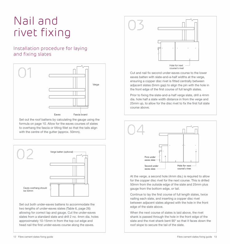
Installation procedure for laying and fixing slates
Nail and rivet fixing
Set out the roof battens by calculating the gauge using theformula on page 10. Allow for the eaves courses of slatesto overhang the fascia or tilting fillet so that the tails alignwith the centre of the gutter (approx. 50mm).
Cut and nail fix second under-eaves course to the lowereaves batten with slate-and-a-half widths at the verge,ensuring a copper disc rivet is fitted centrally betweenadjacent slates (5mm gap) to align the pin with the hole inthe front edge of the first course of full length slates.
Prior to fixing the slate-and-a-half verge slate, drill a 4mmdia. hole half a slate width distance in from the verge and25mm up, to allow for the disc rivet to fix the first full slatecourse above.
At the verge, a second hole (4mm dia.) is required to allowfor the copper disc rivet for the next course. This is drilled50mm from the outside edge of the slate and 25mm plusgauge from the bottom edge, or tail.
Continue to lay the first course of full length slates, twicenailing each slate, and inserting a copper disc rivetbetween adjacent slates aligned with the hole in the frontedge of the slate above.
When the next course of slates is laid above, the rivetshank is passed through the hole in the front edge of theslate and the rivet shank bent 90° so that it faces down theroof slope to secure the tail of the slate.
Set out both under-eaves battens to accommodate thetwo lengths of under-eaves slates (Table 6, page 26)allowing for correct lap and gauge. Cut the under-eavesslates from a standard slate and drill 2 no. 4mm dia. holesapproximately 10-15mm in from the top cut edge andhead nail the first under-eaves course along the eaves.
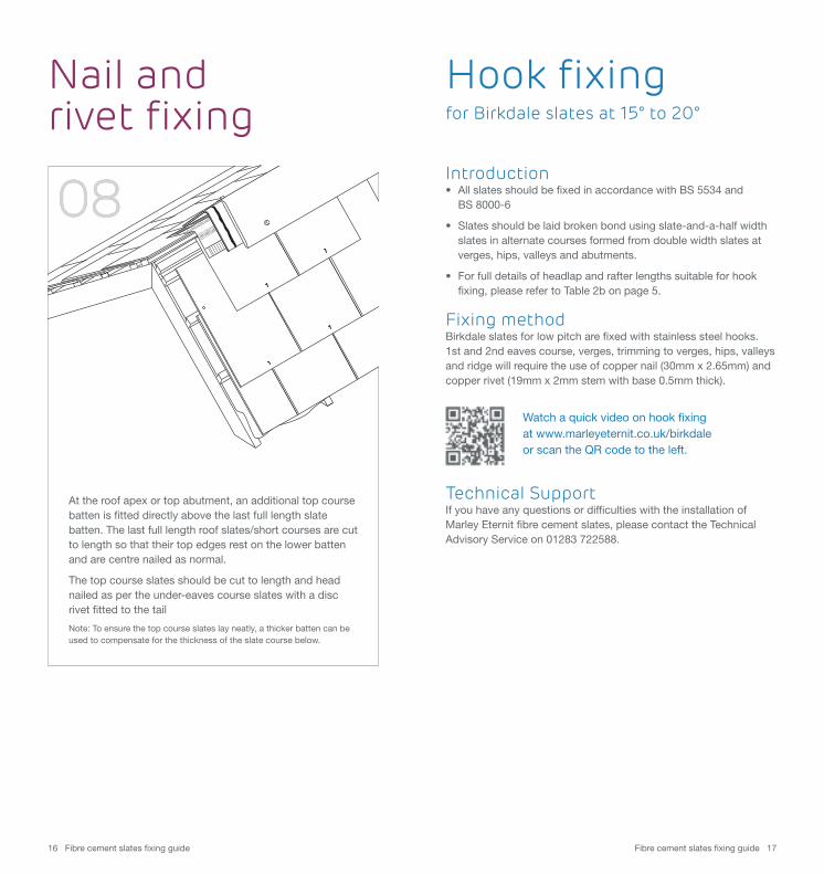
At verges and abutments, lay the first full length slate-and-a-half slate, ensuring that 3 no. 4mm dia. holes are drilledon the batten line with 2 no. additional holes for thecopper disc rivets.
For remaining courses where single and slate-and-a-halfslates are used, a third disc rivet hole is needed to allow forthe rivet pin for the next single width verge slate (at pointC). This is drilled half the single slate width from the side ofthe slate and 25mm plus the gauge distance from the tail.
Fibre cement slates fixing guide 1514 Fibre cement slates fixing guide
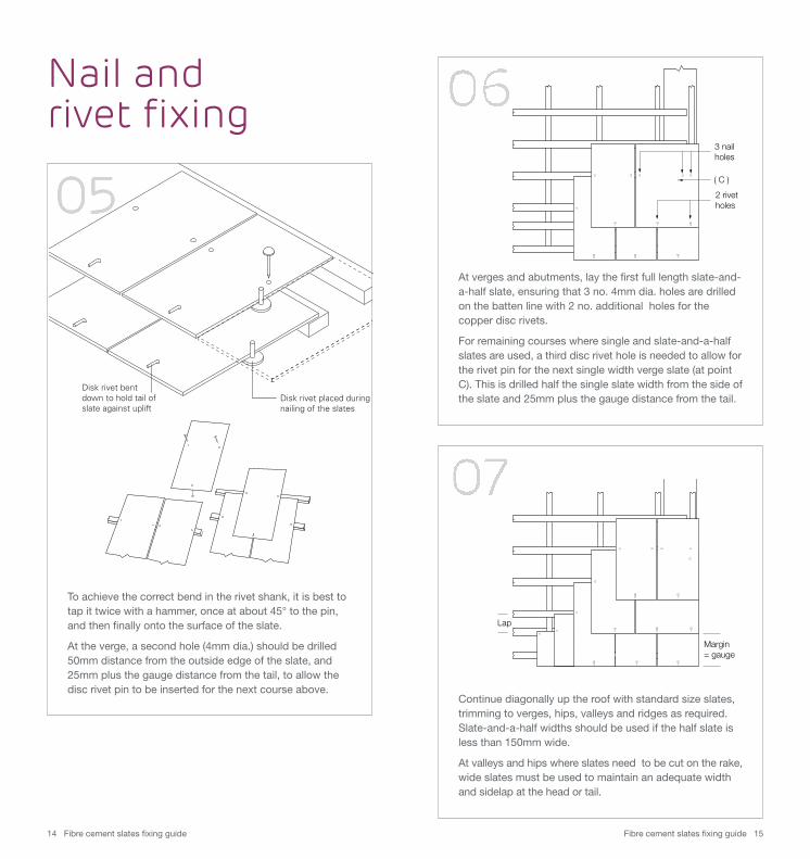
Disk rivet placed duringnailing of the slates
Disk rivet bentdown to hold tail ofslate against uplift
3 nailholes
( C )
2 rivetholes
Nail and rivet fixing
To achieve the correct bend in the rivet shank, it is best totap it twice with a hammer, once at about 45° to the pin,and then finally onto the surface of the slate.
At the verge, a second hole (4mm dia.) should be drilled50mm distance from the outside edge of the slate, and25mm plus the gauge distance from the tail, to allow thedisc rivet pin to be inserted for the next course above.
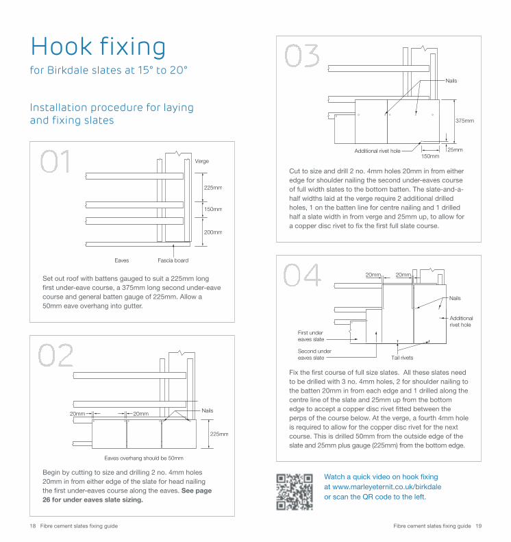
Margin= gauge
Lap
Continue diagonally up the roof with standard size slates,trimming to verges, hips, valleys and ridges as required. Slate-and-a-half widths should be used if the half slate isless than 150mm wide.
At valleys and hips where slates need to be cut on the rake,wide slates must be used to maintain an adequate widthand sidelap at the head or tail.
Fibre cement slates fixing guide 1716 Fibre cement slates fixing guide
Introduction• All slates should be fixed in accordance with BS 5534 and
BS 8000-6
• Slates should be laid broken bond using slate-and-a-half width slates in alternate courses formed from double width slates at verges, hips, valleys and abutments.
• For full details of headlap and rafter lengths suitable for hook fixing, please refer to Table 2b on page 5.
Fixing methodBirkdale slates for low pitch are fixed with stainless steel hooks.1st and 2nd eaves course, verges, trimming to verges, hips, valleysand ridge will require the use of copper nail (30mm x 2.65mm) andcopper rivet (19mm x 2mm stem with base 0.5mm thick).
Technical SupportIf you have any questions or difficulties with the installation ofMarley Eternit fibre cement slates, please contact the TechnicalAdvisory Service on 01283 722588.
Nail and rivet fixing
Hook fixing for Birkdale slates at 15° to 20°
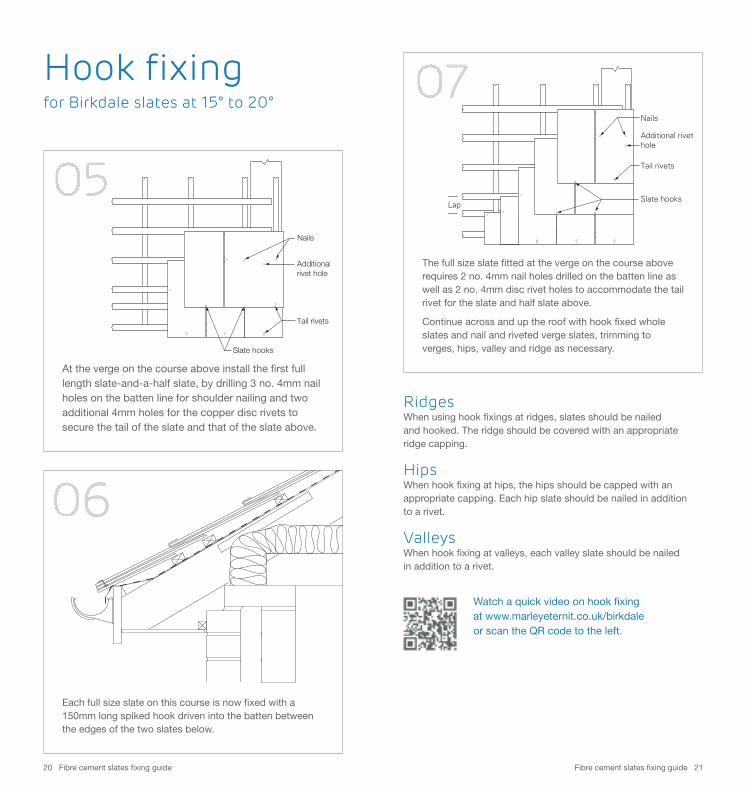
At the roof apex or top abutment, an additional top coursebatten is fitted directly above the last full length slatebatten. The last full length roof slates/short courses are cutto length so that their top edges rest on the lower battenand are centre nailed as normal.
The top course slates should be cut to length and headnailed as per the under-eaves course slates with a discrivet fitted to the tail
Note: To ensure the top course slates lay neatly, a thicker batten can beused to compensate for the thickness of the slate course below.
Watch a quick video on hook fixing at www.marleyeternit.co.uk/birkdaleor scan the QR code to the left.
Watch a quick video on hook fixing at www.marleyeternit.co.uk/birkdaleor scan the QR code to the left.
Fibre cement slates fixing guide 1918 Fibre cement slates fixing guide
Additional rivet hole
Nails
375mm
25mm150mm
Hook fixing for Birkdale slates at 15° to 20°
Installation procedure for laying and fixing slates
Set out roof with battens gauged to suit a 225mm longfirst under-eave course, a 375mm long second under-eavecourse and general batten gauge of 225mm. Allow a50mm eave overhang into gutter.
Begin by cutting to size and drilling 2 no. 4mm holes20mm in from either edge of the slate for head nailingthe first under-eaves course along the eaves. See page 26 for under eaves slate sizing.
Eaves overhang should be 50mm
225mm
20mm20mm Nails
Verge
200mm
150mm
Fascia boardEaves
225mm
Cut to size and drill 2 no. 4mm holes 20mm in from eitheredge for shoulder nailing the second under-eaves courseof full width slates to the bottom batten. The slate-and-a-half widths laid at the verge require 2 additional drilledholes, 1 on the batten line for centre nailing and 1 drilledhalf a slate width in from verge and 25mm up, to allow fora copper disc rivet to fix the first full slate course.
Fix the first course of full size slates. All these slates needto be drilled with 3 no. 4mm holes, 2 for shoulder nailing tothe batten 20mm in from each edge and 1 drilled along thecentre line of the slate and 25mm up from the bottomedge to accept a copper disc rivet fitted between theperps of the course below. At the verge, a fourth 4mm holeis required to allow for the copper disc rivet for the nextcourse. This is drilled 50mm from the outside edge of theslate and 25mm plus gauge (225mm) from the bottom edge.
Additional rivet hole
Nails
First under eaves slate
Second undereaves slate Tail rivets
20mm 20mm
Fibre cement slates fixing guide 2120 Fibre cement slates fixing guide
Nails
Additionalrivet hole
Tail rivets
Slate hooks
Lap
Nails
Tail rivets
Slate hooks
Additional rivet hole
Hook fixing for Birkdale slates at 15° to 20°
At the verge on the course above install the first fulllength slate-and-a-half slate, by drilling 3 no. 4mm nailholes on the batten line for shoulder nailing and twoadditional 4mm holes for the copper disc rivets tosecure the tail of the slate and that of the slate above.
Each full size slate on this course is now fixed with a150mm long spiked hook driven into the batten betweenthe edges of the two slates below.
Watch a quick video on hook fixing at www.marleyeternit.co.uk/birkdaleor scan the QR code to the left.
The full size slate fitted at the verge on the course aboverequires 2 no. 4mm nail holes drilled on the batten line aswell as 2 no. 4mm disc rivet holes to accommodate the tailrivet for the slate and half slate above.
Continue across and up the roof with hook fixed wholeslates and nail and riveted verge slates, trimming toverges, hips, valley and ridge as necessary.
RidgesWhen using hook fixings at ridges, slates should be nailed and hooked. The ridge should be covered with an appropriate ridge capping.
HipsWhen hook fixing at hips, the hips should be capped with anappropriate capping. Each hip slate should be nailed in addition to a rivet.
ValleysWhen hook fixing at valleys, each valley slate should be nailed in addition to a rivet.
Fibre cement slates fixing guide 2322 Fibre cement slates fixing guide
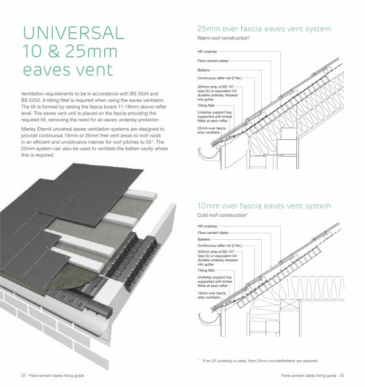
HR underlay
Fibre cement slates
Tilting fillet
25mm over fasciastrip ventilator
Battens
325mm strip of BS 747 type 5U or equivalent UV durable underlay dressed into gutter
Continuous rafter roll (2 No.)
Underlay support traysupported with timberfillets at each rafter
25mm over fascia eaves vent systemWarm roof construction*
HR underlay
Fibre cement slates
Tilting fillet
10mm over fasciastrip ventilator
Battens
325mm strip of BS 747 type 5U or equivalent UV durable underlay dressed into gutter
Continuous rafter roll (2 No.)
Underlay support traysupported with timberfillets at each rafter
10mm over fascia eaves vent systemCold roof construction*
Ventilation requirements to be in accordance with BS 5534 and BS 5250. A tilting fillet is required when using the eaves ventilator.The tilt is formed by raising the fascia board 11-18mm above rafterlevel. The eaves vent unit is placed on the fascia providing therequired tilt, removing the need for an eaves underlay protector.
Marley Eternit universal eaves ventilation systems are designed toprovide continuous 10mm or 25mm free vent areas to roof voids in an efficient and unobtrusive manner for roof pitches to 55°. The25mm system can also be used to ventilate the batten cavity wherethis is required.
UNIVERSAL 10 & 25mmeaves vent
* If an LR underlay is used, then 25mm counterbattens are required.
Fibre cement slates fixing guide 2524 Fibre cement slates fixing guide
For fibre cement slates, it is essential for the function and long termperformance of the roof that three courses of slates are laid at alleaves. Set out the under-eaves battens to accommodate thetypical under-eaves slate lengths as shown in Table 6, page 26.
Eaves battenSize as slating batten.
Tilting filletThe dual purpose of the tilting fillet is to ensure that the underlay is evenly dressed over the fascia to avoid trapping water and inassociation with the fascia, commence the correct laying of theslates. To achieve these functions, the fascia/tilting fillet should beapproximately 8-15mm above the top of the general batten level.
Note: at low pitches, the tilting fillet upslope length should ensure a minimum of 10° slope to the underlay.
Fixing1 Install the underlay parallel to the eaves with the horizontal
overlap appropriate to the rafter-pitch (see page 6).
2 Ensure that the underlay overhangs the fascia sufficiently to drain into the gutter and that dressing the underlay over the tilting fillet prevents any collection of water.
3 Locate and secure the battens to the correct centres appropriate to the size of slate.
4 Follow the slate fixing procedure described on pages 11 to 21.
5 Place rivets between the slates on the second under-eaves course, head resting on the lower slate course. Pass the rivet shank through the hole provided in the first full length slate at its tail. Secure slate and dress the rivet shank down the slope.
6 Proceed laying further full length slates up the roof.
Standard eavesUNIVERSAL 10 & 25mmeaves ventRafter rollThe continuous rafter roll provides a clear airpath over theinsulation irrespective of soffit width and roof pitch by preventingthe insulation blocking the eaves ventilator.
It will accommodate rafter centres from 400mm to 600mm whilststill providing the correct nett free area.
Fixing1 Locate and nail one end of the rafter roll over the rafter.
2 The formation will fit directly onto the rafters at 400mm and 600mm centres.
3 By pulling to extend the length of the panel it may also be attached to rafters at 450mm centres.
4 Subsequent panels should overlap on the rafter fixing.
5 Fix the eaves ventilator onto the rafters with 4 No. 30mm x 8 swg galvanised woodscrews.
6 Lay the underlay over the ventilator, stopping short of the mesh so that air flows through the mesh.
7 Fix the eaves batten so as to allow the underlay to oversail the eaves ventilator unit and not trap water behind the unit.
Note: The eaves ventilator cannot be used with hook fixing systems unless the eaves course is nailed.
For fascia settings height, see the Marley Eternit SiteworkGuide.
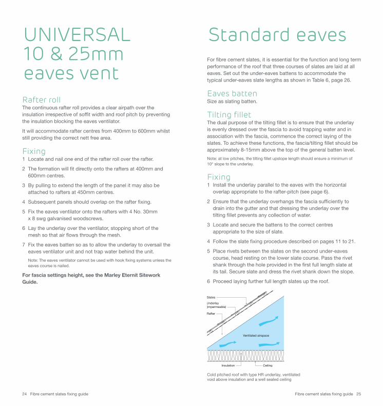
Slates
Underlay (impermeable)
Rafter
Ventilated airspace
Insulation Ceiling
Cold pitched roof with type HR underlay, ventilatedvoid above insulation and a well sealed ceiling
Fibre cement slates fixing guide 2726 Fibre cement slates fixing guide
t
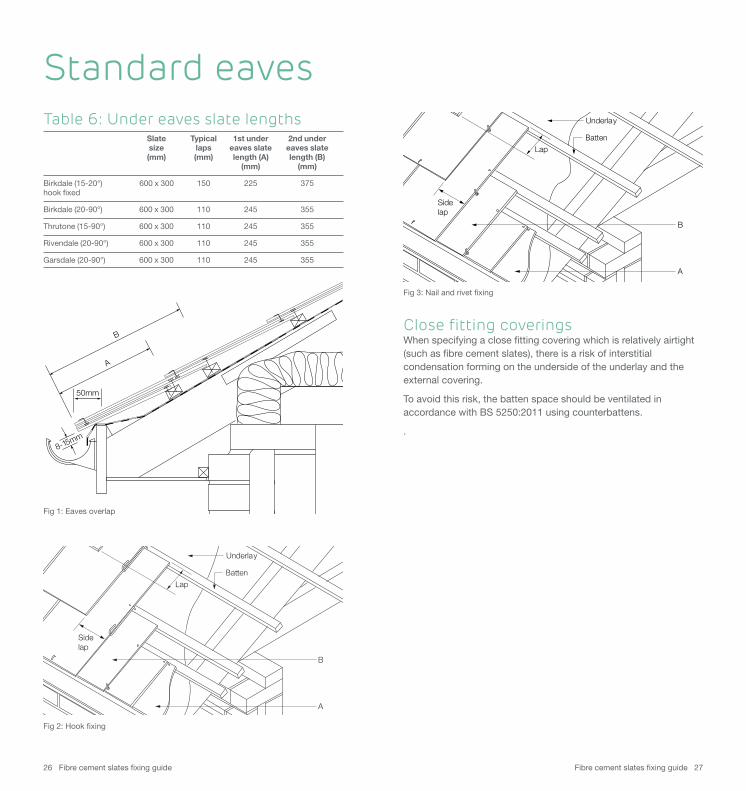
Lap
Sidelap
Underlay
Batten
B
A
Fig 2: Hook fixing
Fig 3: Nail and rivet fixing
Standard eavesTable 6: Under eaves slate lengths Slate Typical 1st under 2nd under size laps eaves slate eaves slate (mm) (mm) length (A) length (B) (mm) (mm)
Birkdale (15-20°) 600 x 300 150 225 375hook fixed
Birkdale (20-90°) 600 x 300 110 245 355
Thrutone (15-90°) 600 x 300 110 245 355
Rivendale (20-90°) 600 x 300 110 245 355
Garsdale (20-90°) 600 x 300 110 245 355
B
A
50mm
8-15mm
Fig 1: Eaves overlap
Close fitting coverings When specifying a close fitting covering which is relatively airtight(such as fibre cement slates), there is a risk of interstitialcondensation forming on the underside of the underlay and theexternal covering.
To avoid this risk, the batten space should be ventilated inaccordance with BS 5250:2011 using counterbattens.
.
Fibre cement slates fixing guide 2928 Fibre cement slates fixing guide
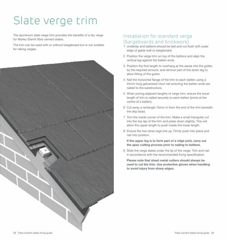
The aluminium slate verge trim provides the benefits of a dry vergefor Marley Eternit fibre cement slates.
The trim can be used with or without bargeboard but is not suitablefor raking verges.
Slate verge trimInstallation for standard verge(bargeboards and brickwork) 1 Underlay and battens should be laid and cut flush with outer
edge of gable wall or bargeboard.
2 Position the verge trim on top of the battens and align the vertical leg against the batten ends
3 Position the first length to overhang at the eaves into the gutter, by the required amount, and remove part of the down leg to allow fitting of the gutter.
4 Nail the horizontal flange of the trim to each batten using a 25mm long galvanised clout nail ensuring the batten ends are nailed to the substructure.
5 When joining adjacent lengths of verge trim, ensure the lower length of trim is nailed securely to each batten (joints at the centre of a batten).
6 Cut away a rectangle 15mm in from the end of the trim beneath the drip bead.
7 Trim the inside corner of the trim. Make a small triangular cut into the top lap of the trim and press down slightly. This will allow the upper length to push inside the lower length.
8 Ensure the two down legs line up. Firmly push into place and nail into position.
If the upper leg is to form part of a ridge joint, carry out the apex cutting process prior to nailing to battens.
9 Slide the verge slates under the lip of the verge. Trim and nail in accordance with the recommended fixing specification.
Please note that sheet metal cutters should always be used to cut the trim. Use protective gloves when handling to avoid injury from sharp edges.
Fibre cement slates fixing guide 3130 Fibre cement slates fixing guide
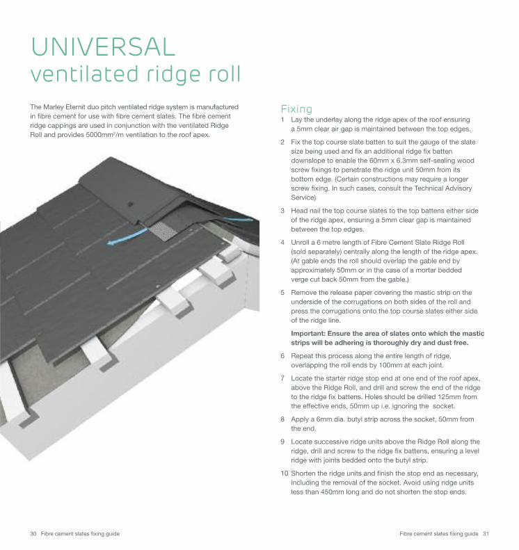
The Marley Eternit duo pitch ventilated ridge system is manufacturedin fibre cement for use with fibre cement slates. The fibre cementridge cappings are used in conjunction with the ventilated RidgeRoll and provides 5000mm2/m ventilation to the roof apex.
Fixing1 Lay the underlay along the ridge apex of the roof ensuring
a 5mm clear air gap is maintained between the top edges.
2 Fix the top course slate batten to suit the gauge of the slate size being used and fix an additional ridge fix batten downslope to enable the 60mm x 6.3mm self-sealing wood screw fixings to penetrate the ridge unit 50mm from its bottom edge. (Certain constructions may require a longer screw fixing. In such cases, consult the Technical Advisory Service)
3 Head nail the top course slates to the top battens either side of the ridge apex, ensuring a 5mm clear gap is maintained between the top edges.
4 Unroll a 6 metre length of Fibre Cement Slate Ridge Roll (sold separately) centrally along the length of the ridge apex. (At gable ends the roll should overlap the gable end by approximately 50mm or in the case of a mortar beddedverge cut back 50mm from the gable.)
5 Remove the release paper covering the mastic strip on the underside of the corrugations on both sides of the roll and press the corrugations onto the top course slates either side of the ridge line.
Important: Ensure the area of slates onto which the mastic strips will be adhering is thoroughly dry and dust free.
6 Repeat this process along the entire length of ridge, overlapping the roll ends by 100mm at each joint.
7 Locate the starter ridge stop end at one end of the roof apex, above the Ridge Roll, and drill and screw the end of the ridge to the ridge fix battens. Holes should be drilled 125mm from the effective ends, 50mm up i.e. ignoring the socket.
8 Apply a 6mm dia. butyl strip across the socket, 50mm from the end.
9 Locate successive ridge units above the Ridge Roll along the ridge, drill and screw to the ridge fix battens, ensuring a level ridge with joints bedded onto the butyl strip.
10 Shorten the ridge units and finish the stop end as necessary, including the removal of the socket. Avoid using ridge units less than 450mm long and do not shorten the stop ends.
UNIVERSAL ventilated ridge roll
Fibre cement slates fixing guide 3332 Fibre cement slates fixing guide
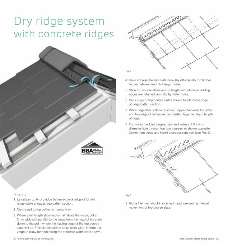
4 Drive appropriate size slate hook (by others) into top timber batten between each full length slate.
5 Slide top course slates (cut to length) into place so leading edges are retained centrally by slate hooks.
6 Back edge of top course slates should touch inside edge of ridge batten section.
7 Place ridge filler units in position, trapped between top slate and top edge of batten section, butted together along length of ridge.
8 For mortar bedded verges, hips and valleys drill a 4mm diameter hole through top two courses as shown opposite 25mm from verge and insert a copper slate nail (see Fig. 6).
9 Ridge filler unit should cover nail head, preventing internal movement of top course slate.
Fixing1 Lay slates up to dry ridge batten so back edge of top full
length slate engages into batten section.
2 Centre nail to top batten in normal way.
3 Where a full length slate-and-a-half abuts the verge, cut a 3mm wide slot parallel to the verge from the head of the slate down to the point where the leading edge of the top course slate will be. This slot should be a half slate width in from the verge to allow for hook fixing the standard width slate above.
25mm
Dry ridge system with concrete ridges
CERTIFICATE No 07/4415
Fig 5
Fig 6
Fibre cement slates fixing guide 3534 Fibre cement slates fixing guide
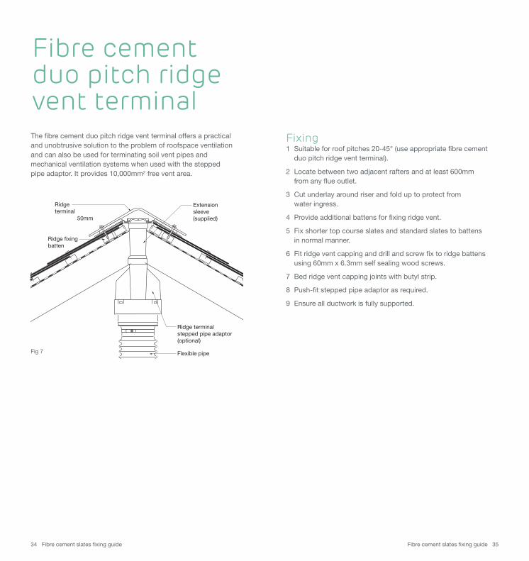
Fibre cement duo pitch ridge vent terminalThe fibre cement duo pitch ridge vent terminal offers a practicaland unobtrusive solution to the problem of roofspace ventilationand can also be used for terminating soil vent pipes andmechanical ventilation systems when used with the stepped pipe adaptor. It provides 10,000mm2 free vent area.
Fixing1 Suitable for roof pitches 20-45° (use appropriate fibre cement
duo pitch ridge vent terminal).
2 Locate between two adjacent rafters and at least 600mm from any flue outlet.
3 Cut underlay around riser and fold up to protect from water ingress.
4 Provide additional battens for fixing ridge vent.
5 Fix shorter top course slates and standard slates to battensin normal manner.
6 Fit ridge vent capping and drill and screw fix to ridge battens using 60mm x 6.3mm self sealing wood screws.
7 Bed ridge vent capping joints with butyl strip.
8 Push-fit stepped pipe adaptor as required.
9 Ensure all ductwork is fully supported.
Flexible pipe
Ridge terminal
Extension sleeve(supplied)
Ridge terminalstepped pipe adaptor (optional)
50mm
Ridge fixingbatten
Fig 7
Fibre cement slates fixing guide 3736 Fibre cement slates fixing guide
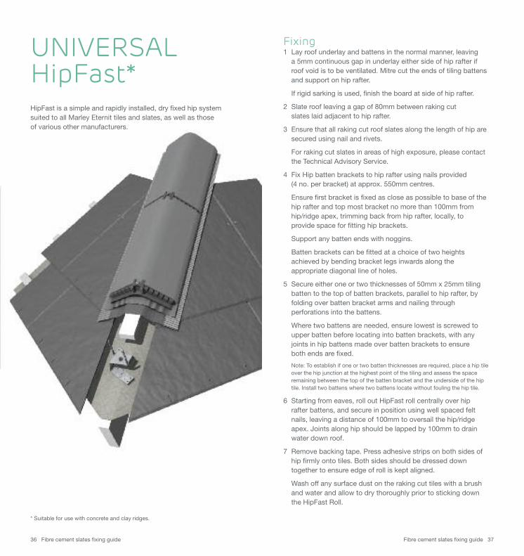
Fixing1 Lay roof underlay and battens in the normal manner, leaving
a 5mm continuous gap in underlay either side of hip rafter if roof void is to be ventilated. Mitre cut the ends of tiling battens and support on hip rafter.
If rigid sarking is used, finish the board at side of hip rafter.
2 Slate roof leaving a gap of 80mm between raking cut slates laid adjacent to hip rafter.
3 Ensure that all raking cut roof slates along the length of hip are secured using nail and rivets.
For raking cut slates in areas of high exposure, please contact the Technical Advisory Service.
4 Fix Hip batten brackets to hip rafter using nails provided(4 no. per bracket) at approx. 550mm centres.
Ensure first bracket is fixed as close as possible to base of the hip rafter and top most bracket no more than 100mm from hip/ridge apex, trimming back from hip rafter, locally, to provide space for fitting hip brackets.
Support any batten ends with noggins.
Batten brackets can be fitted at a choice of two heights achieved by bending bracket legs inwards along the appropriate diagonal line of holes.
5 Secure either one or two thicknesses of 50mm x 25mm tiling batten to the top of batten brackets, parallel to hip rafter, by folding over batten bracket arms and nailing through perforations into the battens.
Where two battens are needed, ensure lowest is screwed to upper batten before locating into batten brackets, with any joints in hip battens made over batten brackets to ensure both ends are fixed.
Note: To establish if one or two batten thicknesses are required, place a hip tile over the hip junction at the highest point of the tiling and assess the space remaining between the top of the batten bracket and the underside of the hip tile. Install two battens where two battens locate without fouling the hip tile.
6 Starting from eaves, roll out HipFast roll centrally over hip rafter battens, and secure in position using well spaced felt nails, leaving a distance of 100mm to oversail the hip/ridge apex. Joints along hip should be lapped by 100mm to drain water down roof.
7 Remove backing tape. Press adhesive strips on both sides of hip firmly onto tiles. Both sides should be dressed down together to ensure edge of roll is kept aligned.
Wash off any surface dust on the raking cut tiles with a brush and water and allow to dry thoroughly prior to sticking down the HipFast Roll.
UNIVERSAL HipFast*HipFast is a simple and rapidly installed, dry fixed hip systemsuited to all Marley Eternit tiles and slates, as well as those of various other manufacturers.
* Suitable for use with concrete and clay ridges.
Fibre cement slates fixing guide 3938 Fibre cement slates fixing guide
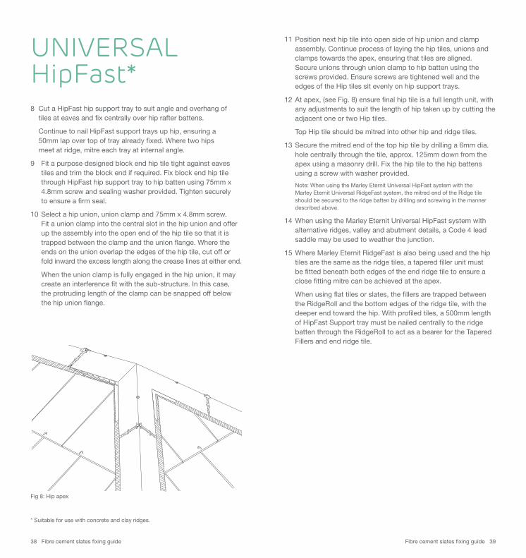
8 Cut a HipFast hip support tray to suit angle and overhang of tiles at eaves and fix centrally over hip rafter battens.
Continue to nail HipFast support trays up hip, ensuring a 50mm lap over top of tray already fixed. Where two hips meet at ridge, mitre each tray at internal angle.
9 Fit a purpose designed block end hip tile tight against eaves tiles and trim the block end if required. Fix block end hip tile through HipFast hip support tray to hip batten using 75mm x 4.8mm screw and sealing washer provided. Tighten securely to ensure a firm seal.
10 Select a hip union, union clamp and 75mm x 4.8mm screw. Fit a union clamp into the central slot in the hip union and offer up the assembly into the open end of the hip tile so that it is trapped between the clamp and the union flange. Where the ends on the union overlap the edges of the hip tile, cut off or fold inward the excess length along the crease lines at either end.
When the union clamp is fully engaged in the hip union, it may create an interference fit with the sub-structure. In this case, the protruding length of the clamp can be snapped off below the hip union flange.
11 Position next hip tile into open side of hip union and clamp assembly. Continue process of laying the hip tiles, unions and clamps towards the apex, ensuring that tiles are aligned. Secure unions through union clamp to hip batten using the screws provided. Ensure screws are tightened well and the edges of the Hip tiles sit evenly on hip support trays.
12 At apex, (see Fig. 8) ensure final hip tile is a full length unit, with any adjustments to suit the length of hip taken up by cutting the adjacent one or two Hip tiles.
Top Hip tile should be mitred into other hip and ridge tiles.
13 Secure the mitred end of the top hip tile by drilling a 6mm dia. hole centrally through the tile, approx. 125mm down from the apex using a masonry drill. Fix the hip tile to the hip battens using a screw with washer provided.
Note: When using the Marley Eternit Universal HipFast system with the Marley Eternit Universal RidgeFast system, the mitred end of the Ridge tile should be secured to the ridge batten by drilling and screwing in the manner described above.
14 When using the Marley Eternit Universal HipFast system with alternative ridges, valley and abutment details, a Code 4 lead saddle may be used to weather the junction.
15 Where Marley Eternit RidgeFast is also being used and the hip tiles are the same as the ridge tiles, a tapered filler unit must be fitted beneath both edges of the end ridge tile to ensure a close fitting mitre can be achieved at the apex.
When using flat tiles or slates, the fillers are trapped between the RidgeRoll and the bottom edges of the ridge tile, with the deeper end toward the hip. With profiled tiles, a 500mm length of HipFast Support tray must be nailed centrally to the ridge batten through the RidgeRoll to act as a bearer for the Tapered Fillers and end ridge tile.
UNIVERSAL HipFast*
Fig 8: Hip apex
* Suitable for use with concrete and clay ridges.
Fibre cement slates fixing guide 4140 Fibre cement slates fixing guide
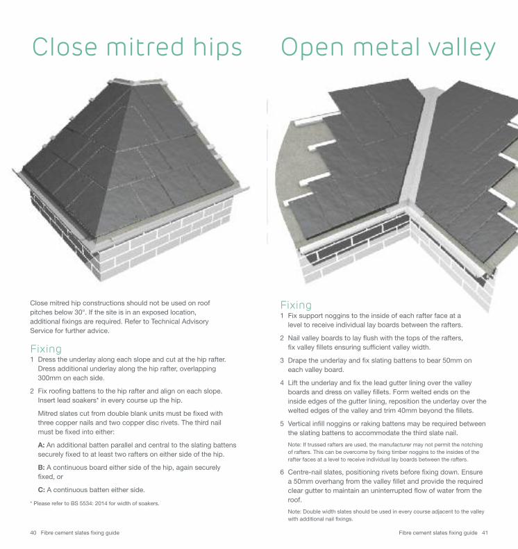
Close mitred hip constructions should not be used on roof pitches below 30°. If the site is in an exposed location, additional fixings are required. Refer to Technical Advisory Service for further advice.
Fixing1 Dress the underlay along each slope and cut at the hip rafter.
Dress additional underlay along the hip rafter, overlapping 300mm on each side.
2 Fix roofing battens to the hip rafter and align on each slope. Insert lead soakers* in every course up the hip.
Mitred slates cut from double blank units must be fixed with three copper nails and two copper disc rivets. The third nail must be fixed into either:
A: An additional batten parallel and central to the slating battens securely fixed to at least two rafters on either side of the hip.
B: A continuous board either side of the hip, again securely fixed, or
C: A continuous batten either side.
* Please refer to BS 5534: 2014 for width of soakers.
Close mitred hips Open metal valley
Fixing1 Fix support noggins to the inside of each rafter face at a
level to receive individual lay boards between the rafters.
2 Nail valley boards to lay flush with the tops of the rafters, fix valley fillets ensuring sufficient valley width.
3 Drape the underlay and fix slating battens to bear 50mm on each valley board.
4 Lift the underlay and fix the lead gutter lining over the valley boards and dress on valley fillets. Form welted ends on the inside edges of the gutter lining, reposition the underlay over the welted edges of the valley and trim 40mm beyond the fillets.
5 Vertical infill noggins or raking battens may be required between the slating battens to accommodate the third slate nail.
Note: If trussed rafters are used, the manufacturer may not permit the notching of rafters. This can be overcome by fixing timber noggins to the insides of the rafter faces at a level to receive individual lay boards between the rafters.
6 Centre-nail slates, positioning rivets before fixing down. Ensure a 50mm overhang from the valley fillet and provide the required clear gutter to maintain an uninterrupted flow of water from the roof.
Note: Double width slates should be used in every course adjacent to the valley with additional nail fixings.
Fibre cement slates fixing guide 4342 Fibre cement slates fixing guide
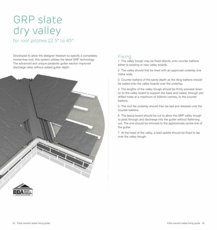
Developed to allow the designer freedom to specify a completelymortar-free roof, this system utilises the latest GRP technology.The advanced and unique parabolic gutter section improvesdischarge rates without added gutter depth.
Fixing1 The valley trough may be fixed directly onto counter battenseither to existing or new valley boards.
2 The valley should first be lined with an approved underlay onemetre wide.
3 Counter battens of the same depth as the tiling battens shouldbe nailed onto the valley boards over the underlay.
4 The lengths of the valley trough should be firmly pressed downon to the valley board to support the base and nailed, through pre-drilled holes at a maximum of 500mm centres, to the counterbattens.
5 The roof tile underlay should then be laid and dressed over thecounter battens.
6 The fascia board should be cut to allow the GRP valley troughto pass through and discharge into the gutter without flatteningout. The end should be trimmed to the approximate centre line ofthe gutter.
7 At the head of the valley, a lead saddle should be fixed to lapover the valley trough.
CERTIFICATE No 93/2909
GRP slate dry valleyfor roof pitches 22.5° to 45°
Fibre cement slates fixing guide 4544 Fibre cement slates fixing guide
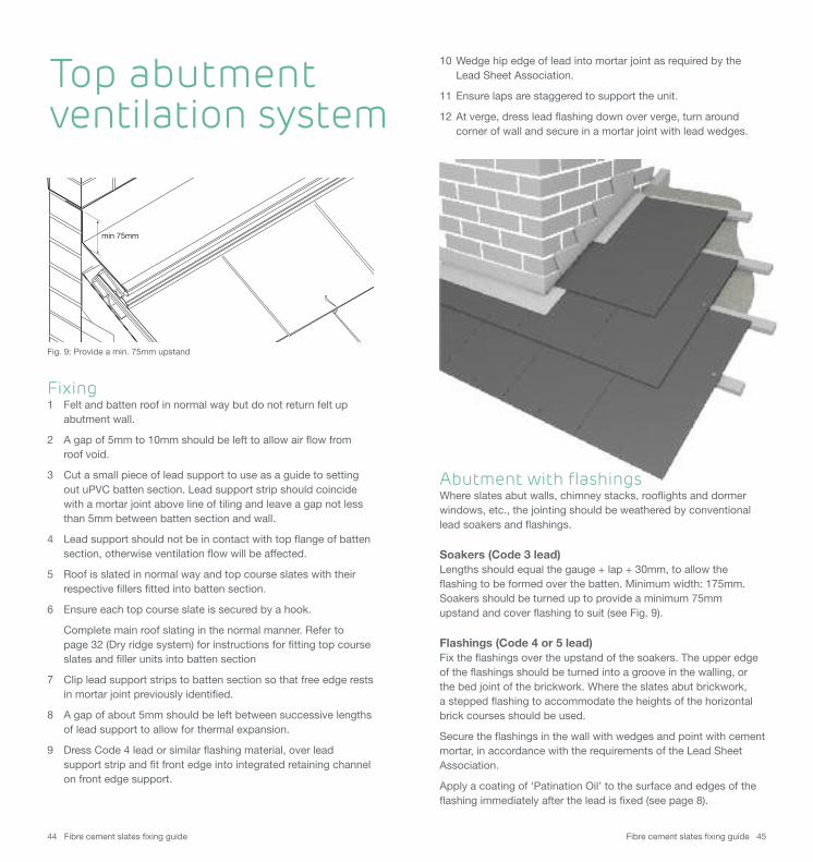
min 75mm
Top abutment ventilation system
Fixing1 Felt and batten roof in normal way but do not return felt up
abutment wall.
2 A gap of 5mm to 10mm should be left to allow air flow from roof void.
3 Cut a small piece of lead support to use as a guide to setting out uPVC batten section. Lead support strip should coincide with a mortar joint above line of tiling and leave a gap not less than 5mm between batten section and wall.
4 Lead support should not be in contact with top flange of batten section, otherwise ventilation flow will be affected.
5 Roof is slated in normal way and top course slates with their respective fillers fitted into batten section.
6 Ensure each top course slate is secured by a hook.
Complete main roof slating in the normal manner. Refer to page 32 (Dry ridge system) for instructions for fitting top course slates and filler units into batten section
7 Clip lead support strips to batten section so that free edge rests in mortar joint previously identified.
8 A gap of about 5mm should be left between successive lengths of lead support to allow for thermal expansion.
9 Dress Code 4 lead or similar flashing material, over lead support strip and fit front edge into integrated retaining channel on front edge support.
10 Wedge hip edge of lead into mortar joint as required by the Lead Sheet Association.
11 Ensure laps are staggered to support the unit.
12 At verge, dress lead flashing down over verge, turn around corner of wall and secure in a mortar joint with lead wedges.
Abutment with flashingsWhere slates abut walls, chimney stacks, rooflights and dormerwindows, etc., the jointing should be weathered by conventionallead soakers and flashings.
Soakers (Code 3 lead)Lengths should equal the gauge + lap + 30mm, to allow theflashing to be formed over the batten. Minimum width: 175mm.Soakers should be turned up to provide a minimum 75mm upstand and cover flashing to suit (see Fig. 9).
Flashings (Code 4 or 5 lead)Fix the flashings over the upstand of the soakers. The upper edgeof the flashings should be turned into a groove in the walling, or the bed joint of the brickwork. Where the slates abut brickwork, a stepped flashing to accommodate the heights of the horizontalbrick courses should be used.
Secure the flashings in the wall with wedges and point with cementmortar, in accordance with the requirements of the Lead SheetAssociation.
Apply a coating of ‘Patination Oil’ to the surface and edges of theflashing immediately after the lead is fixed (see page 8).
Fig. 9: Provide a min. 75mm upstand
Fibre cement slates fixing guide 4746 Fibre cement slates fixing guide
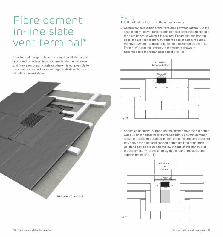
Fixing1 Felt and batten the roof in the normal manner.
2 Determine the position of the ventilator, between rafters. Cut the slate directly below the ventilator so that it does not project past the slate batten to which it is secured. Ensure that the bottom edge of slate vent aligns with bottom edge of adjacent slates. Remove a 280mm section of batten to accommodate the unit. Form a ‘V’ cut in the underlay in the manner shown to accommodate the rectangular spigot (Fig. 10).
Ideal for roof designs where the normal ventilation airpath is blocked by valleys, hips, abutments, dormer windows and firebreaks or party walls or where it is not possible toincorporate standard eaves or ridge ventilation. For use with fibre cement slates.
3 Secure an additional support batten 20mm above the cut batten. Cut a 354mm horizontal slit in the underlay 50-60mm centrallyabove the additional support batten. Slide the underlay protector tray above the additional support batten until the protector’s up-stand can be secured to the lower edge of this batten. Nail the uppermost ‘V’ of the underlay to the rear of the additional support batten (Fig. 11).
Additional support batten
Fibre cement in-line slate vent terminal*
280mm cut between battens
* Minimum 20° roof pitch
Fig. 10
Fig. 11
Fibre cement slates fixing guide 4948 Fibre cement slates fixing guide
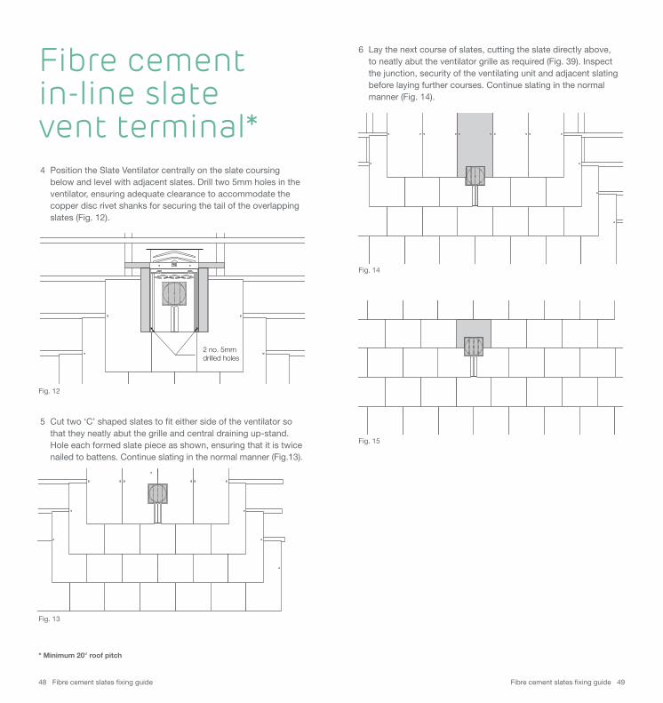
5 Cut two ‘C’ shaped slates to fit either side of the ventilator so that they neatly abut the grille and central draining up-stand. Hole each formed slate piece as shown, ensuring that it is twice nailed to battens. Continue slating in the normal manner (Fig.13).
6 Lay the next course of slates, cutting the slate directly above, to neatly abut the ventilator grille as required (Fig. 39). Inspect the junction, security of the ventilating unit and adjacent slating before laying further courses. Continue slating in the normal manner (Fig. 14).
4 Position the Slate Ventilator centrally on the slate coursing below and level with adjacent slates. Drill two 5mm holes in the ventilator, ensuring adequate clearance to accommodate the copper disc rivet shanks for securing the tail of the overlapping slates (Fig. 12).
2 no. 5mmdrilled holes
Fibre cement in-line slate vent terminal*
* Minimum 20° roof pitch
Fig. 12
Fig. 14
Fig. 15
Fig. 13

Fibre cement slates fixing guide 5150 Fibre cement slates fixing guide
ResourcesTechnical adviceOur Technical Advisory Service is staffed by a qualified team with specialist knowledge.Tel 01283 722588 E-mail [email protected]
Fixing instructions and literature Comprehensive sitework, fixing and installation literatureand videos: marleyeternit.co.uk/resources
All current product and technical literature can be downloaded: marleyeternit.co.uk/downloads
SamplesSamples of clay interlocking and plain tiles, fibre cement slates and concrete tiles are available on request.Tel 01283 722588 marleyeternit.co.uk/samples
Stockist informationTo find details for stockists of Marley Eternit products, visit: marleyeternit.co.uk/stockists
Customer servicesKnowledgeable and friendly staff are available to offerquotations, expert advice, deal with orders and all otherenquiries.Tel 08705 626400 E-mail [email protected]
Sales supportOur Area Sales Managers have in-depth knowledge of yourlocal area. They are available to visit your site to carry out aroof survey, and to offer specific solutions for both new buildand refurbishment projects.marleyeternit.co.uk/localcontacts
TilefixA tool to create fixing specifications based on the geographicallocation and building dimensions of specific building projects.marleyeternit.co.uk/tilefix
EstimatorTool designed to create a complete bill of materials for yourroofing project, based on a wide range of roof shapes:marleyeternit.co.uk/estimator
Training centreWe have a purpose-built training centre where we are able to impart our expertise through a range of practical andclassroom courses. To find out more about our courses, visit: marleyeternit.co.uk/training
Health and safetyIn line with the requirements of the Health and Safety at Work Act, The Consumer Protection Act and The Chemicals(Hazard Information and Packaging for Supply) Regulationsand the Control of Substances Hazardous to HealthRegulations, please view or download copies of our COSHH data sheets at marleyeternit.co.uk/coshh