Embed Size (px)
Citation preview
FM 6-75MHICopy 3
WAR DEPARTMENT
FIELD ARTILLERYFIELD MANUAL
SERVICE OF THE PIECE
15MM HOWMlEtR M2, TRUCK-DRAWN
December 12, 1941
L1~~~~~~~~~~ .I
FM 6-75
FIELD ARTILLERYFIELD MANUAL
SERVICE OF THE PIECE105-NMM HOWITZER, M2, TRUCK-DRAWN
Prepared under direction of theChief of Field Artillery
UNI'IED STATES
GOVERNMENT PRINTING OFFICE
WASHINGTON : 1941
For sale by the Superintendent of Documents. Washington, D.C.
WAR DEPARTMENT,WASHINGTON, December 12, 1941.
FM 6-75, Field Artillery Field Manual, Service of the
Piece-105-mm Howitzer M2, Truck-drawn, is published for
the information and guidance of all concerned.
[A. G. 062.11 (10-14-41).]
BY ORDER OF THE SECRETARY OF WAR:
G. C. MARSHALLIChzef of Staff.
OFFICIAL:
E. S. ADAMS,Major General,
The Adjutant General.
DISTRIBUTION:
Bn and H 6 (4); IB 6 (10); IR 6 (6); IBn 6 (7);
IC 6 (16); IC and H 9 (2).(For explanation of symbols see FM 21-6.)
TABLE OF CONTENTS
SECTION I. General. Paragraph PagePurpose and scope -________________ 1References --- ____________________ 2 1Definitions and terms - -_____________ 3 1
II. Organization.Composition--______________ -_- - ___ 4 2Formation --______________________ 5 2
III. Posts: Mounting and dismounting.Posts of howitzer squad --___________ 6 3To post howitzer squads___________ - - 7 3Posts of cannoneers______________ - -8 3To post cannoneers --_________ ____ 9 4To mount --_______________________ 10 4To dismount --_____________________ 11 6
IV. Movements of the carriages by hand.Coupled_________________________ - -12 7Uncoupled________________________ 13 7
V. Uncoupling and coupling.Uncoupling______________________ - -14 9Coupling-----_____________________ 15 10
VI. Prepare for action and march order.To prepare for action --_________ _ 16 10Posts of cannoneers,. piece un-
coupled - -_________________________ 17 13March order_____________________ - -18 14
VII. Duties in firing.General - -__________-_-___._______ 9 17Chief of section --_________________ 20 17Gunner _____________--____________ 21 22No. 1 -____-_-____ --__-_-_- ________ 22 26No. 2-________________-__-___-- -___ 23 29No.3___________ -_____-___-_______ 24 30No. 4 ---------------------------- 25 31No. 5 ---______________-______ -____ 26 31No. 6--_____----------------------- 27 32No. 7 --_____________________________ 28 32
VIII. Additional information on the service ofthe piece.
Accuracy in laying---______________ 29 33Fire at will-________________-__--_ 30 33Aiming posts --____________________ 31 34Displacement correction--___________ 32 34Reporting errors --_________________ 33 34Cease firing --------- -_____________ 34 35Suspend firing --___________________ 35 35Change in data during firing ------ 36 35To unload piece__________________ - -37 35Misfires_________________________ - -38 36Ammunition - -____________________ 39 36Section data board------___________ 40 36
II

TABLE OF CONTENTS
Paragraph PageSEcrTON IX. Care and maintenance of materiel.
General ---------------------.---- 41 37Inspection ------------------------ 42 38Cleaning -_-------_----__---------- 43 38Lubrication -___------------_------ 44 39Protection against chemicals __---- 45 41Recoil mechanism ___----___------ 46 42Barrel assembly and slides__________ 47 45Breech and firing mechanisms______ 48 47Equilibrator ___-__---------------- 49 49Elevating mechanism and cradle
trunnion bearings-________------- 50 50Wheels and wheel bearings -_______ 51 50Brake mechanism -_________-------- 2 52Sighting and fire-control equip-
ment __-_________________------ 53 53
Iv
FM 6-75
FIELD ARTILLERY FIELD MANUAL
SERVICE OF THE PIECE
105-MM HOWITZER, M2, TRUCK-DRAWN
SECTION I
GENERAL
E 1. PURPOSE AND SCOPE.-This manual prescribes the duties tobe performed in the service of the piece by the personnelnormally assigned to one howitzer section of the firingbattery.
* 2. REFERENCES.-a-C. Description, operation, functioning, andcare of materiel.-TM 9-325; SNL C-21.
b. Description and operation of fire-control and sightingequipment.-TM 9-325; SNL F-1.
c. Ammunition.-TM 9-325; TM 9-1900; SNL R-1.d. Cleaning and preserving materials.-TM 9-850; SNL K-1.e. Automotive driver.-FAM 25-10.f. Maneuvers of battery.-Part Two, FM 6-5.g. Safety precautions in firing.-AR 750-10; FP 6-40.h. Firing battery.-FM 6-40.i. Gunnery.-FM 6-40.j. Reconnaissance, occupation, and organization of posi-
tion.-FM 6-20.
N 3. DEFINITIONS AND TERMS.-a. Section.-Tables of Organi-
zation prescribe the personnel and materiel comprising a sec-tion of a battery. In this manual the term is frequently usedto designate a section of the firing battery. In this restrictedsense, a howitzer section is composed of one piece and theadditional materiel and the personnel required to serve thatpiece.
b. Coupled.-A piece is said to be coupled when its lunetteis attached to the pintle of a truck or other prime mover.
c. Uncoupled.-A piece is said to be uncoupled when itslunette is detached from the pintle of a truck or other primemover and the trail rests on the ground.
d. Front.-The front in a section, carriages coupled, is thedirection in which the trail points; carriages uncoupled, thedirection in which the muzzle of the piece points.
3-5 FIELD ARTILLERY
e. Right (left) .-The direction right (left) is the right (left)of one facing the front.
f. In battery.-A howitzer is said to be in battery when itis in its normal firing position.
SECTION II
ORGANIZATION
· 4. COMPOSITION.-a. Howitzer squad.-A howitzer squadconsists of the gunner and seven cannoneers numbered from1 to 7.
b. Howitzer section.-A howitzer section consists of a chiefof section, a howitzer squad, a driver, and additional can-noneers and an assistant driver who may be assigned orattached. The additional cannoneers act as reliefs or areassigned to other duties as the chief of section may direct.When the section uncouples for drill or for firing, the chiefof section remains at the position of the piece and commandsthe howitzer squad.
c. Ammunition squad.-(1) An ammunition squad consistsof an ammunition corporal and cannoneers as prescribedin Tables of Organization. These cannoneers are numberedconsecutively, beginning with No. 1, and are assigned to theammunition vehicles of the ammunition (fifth) section.
(2) Posts and movements prescribed hereinafter for thehowitzer squad apply with obvious modifications to an ammu-nition squad.
d. Ammunition section.-The ammunition section consistsof the chief of section, the ammunition squad, and the driversof the ammunition trucks of the ammunition (fifth) section.
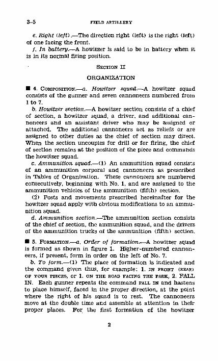
* 5. FORMATION.--a. Order of formation.-A howitzer squadis formed as shown in figure 1. Higher-numbered cannon-eers, if present, form in order on the left of No. 7.
b. To form.-(1) The place of formation is indicated andthe command given thus, for example: 1. IN FRONT (REAR)OF YOUR PIECES, or 1. ON THE ROAD FACING THE PARK, 2. FA.LLIN. Each gunner repeats the command FALL IN and hastensto place himself, faced in the proper direction, at the pointwhere the right of his squad is to rest. The cannoneersmove at the double time and assemble at attention in theirproper places. For the first formation of the howitzer
2
105-MM HOWITZER M2 5-8
squads for any drill or exercise, the caution, "As howitzersquads," precedes the command. The chief of section, ifpresent, supervises the formation.
(2) In case the front or rear of the carriages is desig-nated, each squad falls in at its post (par. 6).
c. To call off.-(1) The command is: CALL OFF. The can-noneer on the left of the gunner calls off "One"; the can-noneer on the left of No. 1, "Two"; and so on.
(2) After having called off, if a subsequent formationis ordered, the cannoneers fall in at once in their properorder.
…CS
2 paces
7|6 5 4 3 2 1 GFIGURE 1.-Formation of howitzer squad.
SECTION III
POSTS: MOUNTING AND DISMOUNTING
1 6. POSTS OF HOWITZER SQUADS.--a. Carriages coupled.-(1) In front of piece.-The squad is in line facing to thefront, its center 2 paces from the front of the truck.
(2) In rear of piece.-The squad is in line facing to thefront, its center 2 paces from the muzzle of the piece.
b. Carriages uncoupled.--In rear of piece.-The squad isin line facing to the front, its center 2 paces from the endof the trail.
B 7. To POST HOWITZER SQUADS.-The squads having beenmarched to the vicinity of the carriages are posted at thecommand SQUADS IN FRONT (REAR) OF YOUR PIECES. Eachgunner marches his squad to its carriage and posts it inthe position indicated.
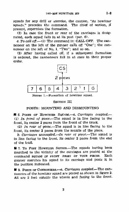
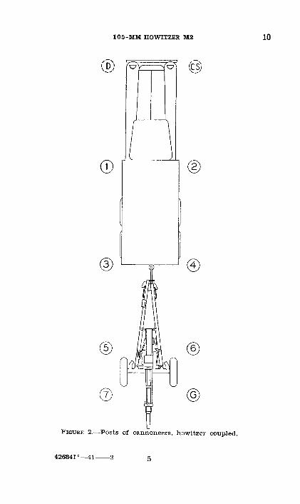
* 8. POSTS OF CANNONEERS.---a. Carriages coupled.-The can-noneers of the howitzer squad are posted as shown in figure 2.All are 2 feet outside the wheels and facing to the front.
3
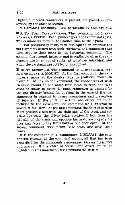
8-10 FIELD ARTILLERY
Higher-numbered cannoneers, if present, are posted as pre-scribed by the chief of section.
b. Carriages uncoupled.-See paragraph 17 and figure 5.
* 9. To POST CANNONEERS.--C. The command is: 1. CA1r-NONEERS, 2. POSTS. Each gunner repeats the command PosIs.The cannoneers move at the double time to their posts.
b. For preliminary instruction, the squads on entering thepark are first posted with their carriages, and cannoneers arethen sent to their posts by the foregoing command. Thecommand is general, however, and is applicable when the can-noneers are in or out of ranks, at a halt or marching, andwhen the carriages are coupled or uncoupled.
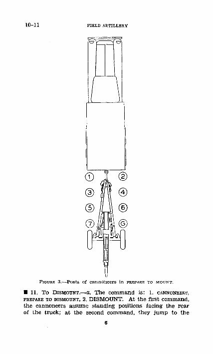
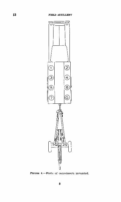
* 10. To MOUNT. -a. The command is: 1. CANNONEERS, PRE-PARE TO MOUNT, 2. MOUNT. At the first command, the can-noneers move at the double time to positions shown infigure 3. At the second command, the cannoneers of bothcolumns mount in the order from head to rear, and takeseats as shown in figure 4. Each cannoneer is assisted bythe one directly behind (or in front in the case of the lastcannoneer in column) to insure promptness and preventionof injuries. If the chief of section and driver are to beincluded in the movement, the command is: 1. PREPARE TOMOUNT, 2. MOUNT. At the first command, the chief of sectiontakes position 2 feet from the right side of the truck and op-posite his seat; the driver takes position 2 feet from theleft side of the truck and opposite his seat; each opens hisdoor and faces to the front holding the door open. At thesecond command, they mount, take seats, and close theirdoors.
b. If the command is: 1. CANNONEERS, 2. MOUNT, the can-noneers execute, at the command MOUNT, all that has beenprescribed for the commands CANNONEERS, PREPARE TO! MOUNTand MOUNT. If the chief of section and driver are to beincluded in this movement, the command is: MOUNT.
4
105-MM HOWITZER M2 10
· o p) ~--- cs
o ®
FIGURE 2.-Posts of cannoneers, howitzer coupled.
426841 --41- 2 5
10-11 FIELD ARTILLERY
o ®
( ®
FIGURE 3.-Posts of cannoneers in PREPARE TO MOUNTT.
* 11. To DISMOUNT.--a. The command is: 1. CANNONEERS,PREPARE TO DISMOUNT, 2. DISMOUNT. At the first command,the cannoneers assume standing positions facing the rearof the truck; at the second command, they jump to the
6
105-MM HOWITZER M2 11-13
ground and, at the double time, take posts as shown in figure2. If the chief of section and driver are to be included inthis movement, the command is: 1. PREPARE TO DISMOUNT, 2.DISMOUNT. At the first command, the chief of section anddriver unlatch their doors and hold them slightly open; atthe second command, they promptly dismount, close theirdoors, and take posts as shown in figure 2.
b. If the command is: 1. CANNONEERS, 2. DISMOUNT, thecannoneers execute, at the command DIsMOUNT, all that hasbeen prescribed for the commands CANNONEERS PREPARE TO DIS-
MOUNT and DISMOUNT. If the chief of section and driver areto be included in this movement, the command is: DIS-MOUNT.
SECTION IV
MOVEMENTS OF THE CARRIAGES BY HAND
0 12. COUPLED.-The carriages are not moved by hand whencoupled.
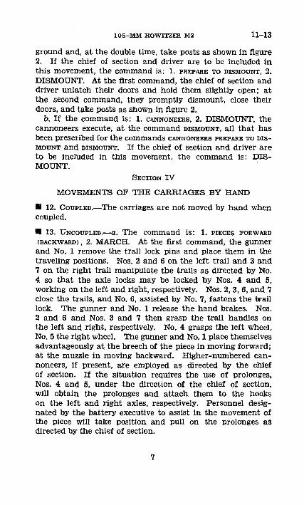
* 13. UNCOUPLED.-a. The command is: 1. PIECES FORWARD(BACKWARD), 2. MARCH. At the first command, the gunnerand No. 1 remove the trail lock pins and place them in thetraveling positions. Nos. 2 and 6 on the left trail and 3 and7 on the right trail manipulate the trails as directed by No.4 so that the axle locks may be locked by Nos. 4 and 5,working on the left and right, respectively. Nos. 2, 3, 6, and 7close the trails, and No. 6, assisted by No. 7, fastens the traillock. The gunner and No. 1 release the hand brakes. Nos.2 and 6 and Nos. 3 and 7 then grasp the trail handles onthe left and right, respectively. No. 4 grasps the left wheel,No. 5 the right wheel. The gunner and No. 1 place themselvesadvantageously at the breech of the piece in moving forward;at the muzzle in moving backward. Higher-numbered can-noneers, if present, are employed as directed by the chiefof section. If the situation requires the use of prolonges,Nos. 4 and 5, under the direction of the chief of section,will obtain the prolonges and attach them to the hookson the left and right axles, respectively. Personnel desig-nated by the battery executive to assist in the movement ofthe piece will take position and pull on the prolonges asdirected by the chief of section.
7
13 FIELD ARTILLERY
© t
'IGURnE 4.-Posts of cannoneers mounted.
8
105-MM HOWITZER M2 13-14
b. At the command MARCH, all move the piece forward(backward) under the direction of the chief of section. Whenthe piece is being moved up or down steep slopes, the gunnerand No. 1 assist by alternately setting and releasing the leftand right brakes, thus permitting the piece to be pivotedabout the alternately locked wheels. At the command HALT,the piece is stopped and reestablished in the firing position;all resume their posts (par. 17).
SECTION V
UNCOUPLING AND COUPLING
U 14. UNCOUPLING.---. General.-At drills, trucks are postedas directed by the battery commander. In active service andin instruction simulating it, the trucks are conducted by thefirst sergeant to a place previously designated by the batterycommander; there they are disposed so as to take the bestadvantage of cover and concealment. If no cover and con-cealment are available, the trucks are located in rear of eitherflank, faced to the front, with wide intervals between them.
b. To fire to front.-The command is: ACTION FRONT.If marching, the trucks halt at the command or signal. Thecannoneers, if mounted, dismount after the trucks havehalted.
(1) Pieces.-The gunner and No. 1 hasten to the wheelsnearest their respective posts. Nos. 2, 3, 6, and 7 hasten tothe trail handles, even numbered cannoneers on the right, oddnumbers on the left. Nos. 4 and 5 go to the muzzle of thepiece, and assist by placing their weight on the tube. No. 3disengages the electric brake cable and safety chain froM-<the.prime mover.- No. 2 unlatches the-pintte-and, %assisted byNos. 3, 6, and 7, raises the trail from the pintle; the gunnersets the left wheel brake. Nos. 2, 3, 4, 5, 6, and 7 swing thepiece 180 ° clockwise. No. 3 releases the drawbar lock andturns the drawbar 180 °, latching it in the firing position.Nos. 2, 3, 6, and 7 then lower the trail to the ground. No. 1sets the right wheel brake. The gunner and all cannoneersthen unload the ammunition, tools, and accessories and ar-range them in an orderly and convenient manner to the leftof the piece. When the unloading has been completed, thechief of section commands or signals DRIVE ON. The gunnerand cannoneers take their posts (par. 17).
9
14-16 FIELD ARTILLERY
(2) Trucks.-At the command DRIVE ON, the trucks moveout and are conducted by the first sergeant to their previouslydesignated position.
c. To fire to rear.-The command is: ACTION REAR. Themovement is executed according to the principles of ACTIONFRONT. The piece is not turned after uncoupling.
d. To fire to flank.-The command is: ACTION RIGHT(LEFT). The movement is executed according to the princi-ples of ACTION FRONT, with the following modifications: Afterthe piece is uncoupled, the trail is turned 90° away from thedirection of fire, and the piece is run forward sufficiently toclear the track made by the truck; articles unloaded from thetruck are placed on the ground so as to clear the track madeby the truck.
E 15. CoUPLING.--a. The pieces being in position and inmarch order, the command is: COUPLE. The trucks, underthe command of the first sergeant, approach the position fromthe right (left) flank. As each truck approaches its piece, itturns to the left (right) and halts in prolongation of the trailof the piece.
b. All cannoneers working together under the direction ofthe chief of section load the tools, accessories, and unex-pended ammunition. Nos. 2, 3, 6, and 7 hasten to the trailhandles, even-numbered cannoneers on the left, odd-num-bered on the right. Nos. 4 and 5 hasten to the muzzle ofthe piece. The gunner and No. 1 release the brakes. Thetruck, upon signal from the chief of section, is maneuveredbackward until the pintle is almost over the lunette. Nos.2, 3, 6, and 7 then raise the trail and, after No. 3 has placedthe drawbar in traveling position, place the lunette over thepintle, No. 2 latching the pintle. Nos. 4 and 5 assist byplacing their weight on the tube. No. 3 engages the electricbrake cable and safety chain to the prime mover. The chiefof section verifies that the brakes are operating properly.All cannoneers take their posts.
SECTION VI
PREPARE FOR ACTION AND MARCH ORDER
* 16. To PREPARE FOR ACTION.--a. The piece being in posi-tion uncoupled, the command is: PREPARE FOR ACTION.Duties of individuals are as follows:
10
105-MM HOWITZER M2 16
(1) Chief of section.-(a) Supervises the work of thecannoneers.
(b) Inspects the mat6riel; verifies the fact that the recoilmechanism contains the proper amount of oil and that allis in order; and, when the operations have been completed,reports to the executive, "Sir, No. (so-and-so) in order," orreports any defects that the section cannot remedy withoutdelay.
(2) Gunner-(a) Assisted by No. 1, removes the breechend of the howitzer cover.
(b) Releases the left hand brake momentarily while trailsare being spread, to permit action of the equalizer axle.
(c) Places the left trail lock pin in the firing position.(d) Removes the panoramic telescope from its case, and
seats it in the telescope mount.(e) Uncovers the telescope mount bubbles; sets the index
of the rotating head at zero, the deflection at zero, andlevels both bubbles.
(f) Takes his post.(3) No. 1.-(a) Releases the traveling lock.(b) Assists the gunner in removing the breech end of the
howitzer cover, throwing the cover to the right of the rightwheel.
(c) Releases the right hand brake momentarily whiletrails are being spread, to permit action of the equalizeraxle.
(d) Places the right trail lockpin in the firing position.(e) Operates elevation handwheel to assist No. 4 in unlock-
ing cradle lock.(f) Uncovers the range quadrant bubbles; if directed by
the executive, replaces the range drum for Charge V withthe designated drum; sets site 300 and range 3,000, and levelsthe bubbles.
(g) Operates the breech mechanism, and examines thebreechblock, chamber, and bore, cleaning any parts requiringit; leaves the breech open.
(h) When so directed by the executive, removes the elbowtelescope from its case and seats it in its mount.
(i) Takes his post.(4) No. 2.(a) Spreads the left trail, assisted by No. 6,
when No. 4 calls "Spread."
11
16 FIELD ARTILLERY
(b) Removes the rammer staff from its traveling position,assembles it to the rammer (bore brush), and places it tothe right of the piece.
(c) When so directed, assists No. 1 in cleaning the breechmechanism, chamber, and bore of the howitzer.
(d) Folds the muzzle and breech ends of the howitzercover, and places them on the ground to the right of theright wheel of the howitzer.
(e) Takes his post.(5) No 3.-(a) Unlocks the drawbar lock, and turns and
locks the drawbar in firing position.(b) Spreads the right trail, assisted by No. 7, when No. 4
calls "Spread."(c) Arranges the ammunition and tools, assisted by Nos.
4, 5, 6, and 7.(d) Obtains the fuze setter from the section chest, and
places it convenient to the position of the ammunition.(e) Takes his post.(6) No. 4.-(a) Unlocks the left axle lock from the travel-
ing position and latches it in the firing position; when hesees that both axle locks are unlocked, calls "Spread," toinform Nos. 2 and 3 that trails may be spread.
(b) Unlocks the cradle lock, assisted by No. 1 operatingthe elevation handwheel, and latches it in firing position.
(c) Removes the muzzle end of the howitzer cover, assistedby No. 5.
(d) When so directed, lowers left top shield, and locks itin the lowered position.
(e) Assists No. 3 in arranging the ammunition and tools.(I) Takes his post.(7) No. 5.-(a) Unlocks the right axle lock from the travel-
ing position and latches it in the firing position.(b) Assists No. 4 to remove the muzzle end of the howitzer
cover, and throws it on the ground to the right of the rightwheel.
(c) Removes the aiming posts from the traveling positionand places them beside the rammer staff.
(d) Assists No. 3 in arranging the ammunition and tools.(e) Takes his post.(8) No. 6.-(a) Unlocks the trail lock.(b) Removes the trail handspike from its traveling position
and places it in its socket on the left trail.
12
105-MM HOWITZER M2 16-17
(c) Assists No. 2 in spreading the left trail.(d) Places the section chest, assisted by No. 7, immediately
to thd left of the piece.(e) Assists No. 3 in arranging the ammunition and tools.(f) Distributes waste to the cannoneers.(g) Takes his post.(9) No. (7.-(a) Assists No. 3 to spread the right trail.(b) Assists No. 6 to place the section chest to the left
of the piece.(c) Assists No. 3 in arranging the ammunition and tools.(d) Takes his post.b. The coupled piece may be partially prepared for action
before reaching the firing position. The duties of the can-noneers are the same as in preparing for action when thepiece is uncoupled, but only such operations as are practi-cable are carried out. Immediately after the piece is estab-lished in position, preparation for action is completed withoutcommand, and the cannoneers take their posts for firing thepiece.
c. If PREPARE FOR ACTION has not been ordered before thepiece is established in the firing position, the command ishabitually given by the chief of section as soon as the piecehas been uncoupled. If this is not desired, the caution, "Donot prepare for action," must be given.
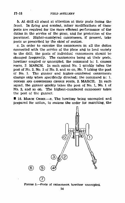
* 17. POSTS OF CANNONEERS, PIECE UNCOUPLED (fig. 5) .- a. Thepiece having been uncoupled, posts are taken as follows:
(1) Chief of section.-The chief of section goes where hecan control the service of the piece, hear commands, andperform his duties effectively. A convenient post is betweenthe trail spades and on line with them.
(2) Gunner.-Immediately behind the left wheel andoutside the trail.
(3) No. 1.-Immediately behind the right wheel andoutside the trail.
(4) No. 2.-Three feet in rear of the gunner, covering him,and inside the trail.
(5) No. 3.-Two feet to the left of No. 2.(6) No. 4.-Two feet in rear of No. 3, covering him.(7) No. 5.-Two feet to the left of No. 4.(8) No. 6.-Two feet to the left of No. 5.(9) No. 7.-Two feet in rear of No. 5, covering him.
426841 °- - 4 1- - - - -313
17-18 FIELD ARTILLERY
b. At drill all stand at attention at their posts facing thefront. In firing and combat, minor modifications of theseposts are required for the more efficient performance of theduties in the service of the piece, and for protection of thepersonnel. Higher-numbered cannoneers, if present, takeposts as prescribed by the chief of section.
c. In order to exercise the cannoneers in all the dutiesconnected with the service of the piece and to lend varietyto the drill, the posts of individual cannoneers should bechanged frequently. The cannoneers being at their posts,howitzer coupled or uncoupled, the command is: 1. CHANGEPOSTS, 2. MARCH. In each squad No. 1 quickly takes thepost of No. 2, No. 2 of No. 3, and so on, No. 7 taking the postof No. 1. The gunner and higher-numbered cannoneerschange only when specifically directed; the command is: 1.GUNNER AND CANNONEERS CHANGE POSTS, 2. MARCH. In eachsquad, the gunner quickly takes the post of No. 1, No. 1 ofNo. 2, and so on. The highest-numbered cannoneer takesthe post of the gunner.
3 18. MARCH ORDER.-a. The howitzer being uncoupled andprepared for action, to resume the order for marching, the
F'nGUmE 5.-Posts of cannoneers, howitzer uncoupled.14
105-MM HOWITZER M2 18
command is: MARCH ORDER. Duties of individuals areas follows:
(1) Chief of section.-(a) Supervises the work of thecannoneers.
(b) Inspects the materiel; makes sure that the piece isnot loaded and that the traveling lock and cradle lock arelocked in the traveling position; and, when the operationshave been completed, reports to the executive, "Sir, No.(so-and-so) in order," or reports any defects which thesection cannot remedy without delay.
(2) Gunner.-(a) Places the piece in the center of traverse.(b) Removes left trail lock pin from the firing position
and places it in the traveling position.(c) Sets the rotating head and deflection at zero and
closes the covers on the telescope mount leveling bubbles.(d) Removes the telescope from the mount, returns it to
its case, and locks the case.(e) Replaces the breech end of the howitzer cover, assisted
by No. 1.(f) Takes his post.(3) No. 1.-(a) Operates elevation handwheel to assist
No. 4 in locking cradle lock.(b) Removes the right trail lock pin from the firing posi-
tion and places it in traveling position.(c) Inspects the chamber to see that piece is unloaded and
closes breech.(d) Locks the traveling lock, after the trails have been
closed and locked.(e) Assists the gunner in replacing the breech end of the
howitzer cover.(f) Takes his post.(4) No. 2.-(a) Closes the left trail, assisted by No. 6.(b) Disassembles the rammer staff; removes the rammer
(bore brush) and places it in the section chest; secures therammer staff in its traveling position on the trail.
(c) Takes his post.(5) No. 3.-(a) Closes the right trail, assisted by No. 7.(b) Turns and locks the drawbar in its traveling position.(c) Places the fuze setter in the section chest.(d) Prepares ammunition and tools, assisted by Nos. 4, 5,
6, and 7, for loading in the prime mover.(e) Takes his post.
15
18 FIELD ARTILLERY
(6) No. 4.-(a) Locks the cradle lock in the travelingposition, assisted by No. 1 operating the elevation handwheel.
(b) Locks the left axle lock in the traveling position.(c) Raises and locks the left top shield, if down.(d) Replaces the muzzle end of the howitzer cover,
assisted by No. 5.(e) Assists No. 3 in preparing the ammunition and tools
for loading in the prime mover.(f) Takes his post.(7) No. 5.-(a) Locks the right axle lock in the traveling
position.(b) Assists No. 4 in replacing the muzzle end of the howitzer
cover.(c) Secures the aiming posts in the traveling position on
the trail.(d) Assists No. 3 in preparing the ammunition and tools
for loading in the prime mover.(e) Takes his post.(8) No. 6.-(a) Assists No. 2 in closing the left trail.(b) Assisted by No. 7, locks trail lock.(c) Removes the trail handspike from the left trail and
secures it in its traveling position.(d) Prepares the section chest for loading in the prime
mover, assisted by No. 7.(e) Assists No. 3 in preparing the ammunition and tools
for loading in the prime mover.(f) Takes his post.(9) No. 7.-(a) Assists No. 3 in closing the right trail.(b) Assists No. 6 in locking the trail lock.(c) Assists No. 3 in placing the drawbar in the traveling
position.(d) Assists No. 6 in preparing the section chest for loading
in the prime mover.(e) Assists No. 3 in preparing the ammunition and tools
for loading in the prime mover.(f) Takes his post.b. To resume fire in another position.-(1) If firing is to be
resumed shortly in another position to which the piece mustbe towed by its prime mover, the command MARCH ORDER isnot given. In this case, at the command for coupling, onlysuch of the operations incident to march order are per--
16
105-MM HOWITZER M2 18-20
formed as are necessary for the movement of the piece andfor the care and security of the equipment.
(2) If the command MARCH ORDER is given while the pieceis coupled, the operations pertaining to march order arecompleted.
SECTION VII
DUTIES IN FIRING
I 19. GENERAL.-In general the duties in firing are as follows:a. The chief of section is responsible that all duties are
properly performed, all commands executed, and all safetyprecautions observed.
b. The gunner sets the announced deflection, lays for direc-tion, and refers the piece.
c. No. 1 sets the announced site and range (elevation),opens and closes the breech, and fires the piece.
d. No. 2 loads the piece.e. No. 3 operates the fuze setter and makes the proper set-
ting of fuzes.f. No. 4 assists No. 3 in setting fuzes, and passes the rounds
to No. 2 for loading.g. No. 5, assisted by Nos. 6 and 7, prepares charges and
passes the reassembled round to No. 4.h. Nos. 6 and 7 remove ammunition from the containers
and assist No. 5 in preparing charges and reassemblingrounds. No. 7 keeps empty cartridge cases out of the way ofthe cannoneers.
N 20. CHIEF OF SECTION.-a. Enumeration of duties.-(1) Tolay for elevation, assisted by No. 1, when the gunner'squadrant is used.
(2) To measure the elevation (range).(3) (a) To measure the minimum quadrant elevation.(b) To measure the minimum range (elevation).(4) To indicate to the gunner the aiming point, the refer-
ring point, or the target.(5) To follow fire commands.(6) To indicate when the piece is ready to fire.(7) To give the command to fire except when firing on
moving targets with direct laying.(8) To report errors and other unusual incidents of fire to
the executive.
17
20 FIELD ARTILLERY
(9) To conduct prearranged firing schedules.(10) To record basic data.(11) To observe and frequently check the functioning of
the matdriel.(12) To assign duties when firing with reduced personnel..(13) To conduct the fire of his piece on a moving target
when so ordered by the executive.b. Detailed description of certain duties.-(1) To lay for
elevation when gunner's quadrant is used.-(a) The corn-mand QUADRANT (SO MUCH) indicates that the gunner's quad-rant is to be used.
(b) To set an elevation on the gunner's quadrant, for ex-ample, 361.8 mils, the chief of section sets the upper edge ofthe head of the index arm opposite the 360 mark of thegraduated arc on the quadrant frame; he then slides theslide level along the index arm until the index of the slidelevel is opposite the 1.8 mark of the scale on the index arm.In setting the slide, the chief of section must be careful touse the scale on the index arm which is on the same side ofthe quadrant as the graduated arc he used in setting the indexarm at 360 mils. After he has set the slide, he tightens theclamp just enough to hold the slide in place.
(c) The announced elevation having been set on the gun-ner's quadrant, the piece loaded, and the breechblock closed,the chief of section places the quadrant on the quadrant seat,with the words "line of fire" at the bottom and the arrowpointing toward the muzzle. The chief of section must besure to use the arrow which appears on the same side of thequadrant as the scale which he is using. He stands squarelyopposite the side of the quadrant and holds it firmly on thequadrant seat, parallel to the axis of the bore. It is importantthat he take the same position and hold the quadrant in thesame manner for each subsequent setting, so that in each casehe will view the quadrant bubble from the same angle.
(d) No. 1 operates the elevating handwheel until the quad-rant bubble is centered, making sure that the last movementis in the direction in which it is most difficult to turn thehandwheel. The chief of section warns No. 1 when thebubble is approaching the center, in order that the finalcentering may be performed accurately.
(2) To measure elevation (range).-At the commandMEASURE THE ELEVATION (RANGE), the piece having been laid,
18
105-MM HOWITZER M2 20
the chief of section causes No. 1 to set site 300 and, withthe elevating knob, to level the range quadrant elevatingbubble. The chief of section then reads the elevation (range)set on the elevation scale (range drum) and announces theelevation (range) thus set; for example, "Elevation (range)No. (so-and-so), (so much)."
(3) To measure minimum quadrant elevation or minimumelevation (range).--(a) Quadrant elevation.-The commandis: MEASURE THE MINIMUM QUADRANT ELEVATION.The chief of section, sighting along the lowest element of thebore, causes No. 1 to operate the elevating mechanism untilthe line of sight just clears the crest. He then measuresthe quadrant elevation and, after reading the angle on thequadrant, reports it to the executive thus: "Minimum quad-rant elevation No. (so-and-so), (so much)."
(b) Elevation.-The command is: MEASURE THE MINI-MUM ELEVATION, SITE (SO MUCH) .- The chief of sectioncauses No. 1 to set the site announced. Then, sighting alongthe lowest element of the bore, he causes No. 1 to operatethe elevating handwheel until the line of sight just clearsthe crest. No. 1 then levels the bubble of the range quadrantby turning the elevating knob. The chief of section readsthe elevation setting and reports it to the executive thus:"Minimum elevation No. (so-and-so), (so much), site (somuch) ."
(c) Range.-The command is: MEASURE THE MINIMUMRANGE, CHARGE (SO-AND-SO), SITE (SO MUCH). Thechief of section causes No. 1 to install the range drum forthe announced charge, and to set the site announced. Then,sighting along the lowest element of the bore, he causes No.1 to operate the elevating handwheel until the line of sightjust clears the crest. No. 1 then levels the bubble of therange quadrant by turning the elevating knob. The chiefof section reads the range setting and reports it to the execu-tive thus: "Minimum range, No. (so-and-so), (so much),charge (so-and-so), site (so much)."
(d) When the executive announces the minimum quadrantelevation or the minimum elevation (range), charge, andsite, the chief of section records it in a notebook and causesthe gunner to chalk it on a convenient place on the carriage.
(4) To indicate to gunner the aiming point, referring point,or target.-Whenever an aiming point, a referring point, or
19
20 FIELD ARTILLERY
a target has been designated by the executive, the chief ofsection will make sure that he has properly identified thepoint in question. He will then indicate it to the gunner. Ifthere is any possibility of misunderstanding, the chief ofsection will turn the telescope until the horizontal and verticalhairs are on the point designated.
(5) To follow fire commands.-The chief of section will fol-low the fire commands mentally. He will not repeat thecommands, but will be prepared to give any element of the lastcommand to any cannoneer who has failed to hear it.
(6) To indicate when piece is ready to fire.-When the ex-ecutive can see arm signals of the chief of section, the chiefof section will extend his right arm vertically as a signalthat the piece is ready to fire. He gives the signal as soonas the gunner calls "Ready." When arm signals cannot beseen, the chief of section reports orally to the executive,"No. (so-and-so) ready."
(7) To give command to fire.-When No. 1 can see arm sig-nals made by the chief of section, the chief of section will givethe command to fire by dropping his right arm sharply tohis side. When his arm signals cannot be seen, he orallycommands: NO. (SO-AND-SO) FIRE. The chief of sectionwill not give the signal or command to fire until all the can-noneers are in their proper places. He will require the can-noneers to stand clear of the piece for the first round.
(8) To report errors and other unusual incidents of fireto executive.-If for any reason the piece cannot be fired,the chief of section will promptly report that fact to theexecutive, and the reason therefor; for example, "No. (so-and-so) out, misfire." Whenever it is discovered that the piecehas been fired with an error in laying, the chief of sectionwill report that fact at once; for example, "No. (so-and-so)fired with incorrect deflection." Whenever the gunner re-ports that the aiming posts are out of alinement with thetelescope, the chief of section will report that fact and requestinstructions. Likewise, he promptly reports other unusualincidents that affect the service of the piece. (See par. 33.)
(9) To conduct prearranged fire schedules.-Whenever theexecution of prearranged fire schedules is ordered, the chiefof section will conduct the fire of his section in strict con-formity to the schedule prescribed.
(10) To record basic data.-The chief of section will record
20
105-MM HOWITZER M2 20
in a notebook data of a semipermanent nature. These in-clude such data as minimum elevations; base deflections, in-cluding aiming points used; prearranged fires when preparedschedules are not furnished; safety limits in elevation anddeflection; number of rounds fired, with the date and hour;and calibration corrections when appropriate.
(11) To observe and check functioning of materiel.-Thechief of section closely observes the functioning of all partsof the matkriel during firing. Before the piece is fired, heverifies the fact that the recoil mechanism contains theproper amount of oil; thereafter he carefully observes thefunctioning of the recoil system. He promptly reports to theexecutive any evidence of trouble (par. 46).
(12) To assign duties when firing with reduced personnel.-Whenever the personnel of the section serving the piece istemporarily reduced in numbers below that indicated in thismanual, the chief of section will make such redistribution ofduties as will best facilitate the service of the piece.
(13) During direct laying on moving target, to conduct fireof his piece when so ordered by executive.-(a) Initial lead.-The chief of section observes the target, estimates its lateralspeed, and (based on the speed) estimates the lead in targetlengths.
(b) Initial range or elevation.-The chief of section esti-mates the initial range to the target and announces therange or the corresponding elevation. The announced rangeis used by the gunner when he lays for range (par. 21b(8))and by No. 1 when he lays for range using the elbow telescope(par. 22b(2) (b)). The announced elevation is used by No. 1in laying for elevation (par. 22b(3) (b)). The chief of sec-tion announces the elevation which is the algebraic sum ofthe range elevation and angle of site. For rapid determina-tion of the elevation he should be furnished with a tabulatedcard for Charge VII, showing the elevation setting for plusand minus angles of site and ranges for which such fire maybe used. He is trained to determine the range and measurethe site to various points in the sector from which enemycombat vehicles may be expected to appear. These axerecorded and should be memorized by him. They are usedin determining the initial elevation announced.
(c) To announce an initial range (elevation) and lead.-The command is: TARGET (SO-AND-SO), RANGE (ELE-
426841'--41-4 21
20-21 FIELD ARTILLERY
VATION) (SO MUCH), LEAD (SO MANY) TARGETLENGTHS.
(d) To announce a change in range (elevation) and lead.--The chief of section observes the fire of his piece, and whenthe gunner or No. 1 is not tracking the target effectively, heannounces a range change or a new lead. The announcedchange in range or elevation is given in yards. The commandis: UP (DOWN) (SO MUCH). The announced change inlead is given as a new lead in the number of target lengths.The command is: LEAD (SO MANY).
U 21. GUNNER.-a. Enumeration of duties.-(1) (a)To centerthe bubbles on the telescope mount.
(b) To set or change the deflection.(c) To apply the deflection difference.(d) To lay for direction.(e) To call "Ready."(f) To refer the piece.(g) To record base deflection.(h) To measure a deflection.(i) To take and maintain an announced lead during direct
laying on a moving target.(j) When directed, to lay for range as well as direction,
during direct laying on a moving target.(k) To give the command to fire during direct laying on
a moving target.(2) For indirect laying or direct laying on a stationary
target, the gunner performs the duties prescribed in (1) (a),(b), (c), (d), and (e) above.
(3) For direct laying on a moving target, the gunner per-forms the duties prescribed in (1) (a), (i), and (k) and,when directed, in (j) above.
(4) When directed, the gunner performs the dutiesprescribed in (1) (f), (g) and (h) above.
b. Detailed description of certain duties.--(1)To set orchange deflection.--(a) TO set deflection.-At the command,for example, DEFLECTION, 1,885, the gunner first sets thezero of the azimuth micrometer opposite the fixed index, ifit is not already so set. He then pushes the throw-out leverand turns the rotating head until the hundreds- graduation(18 in this case) is opposite the azimuth-scale index. Hethen releases the throw-out lever and, grasping the deflection
22
105-MM HOWITZER M2 21
knob with his left hand, with the thumb on top, turns theknob to the left until the micrometer index is opposite thegraduation 85 of the counterclockwise graduations on theazimuth micrometer. The line of sight will then make ahorizontal angle of 1,885 mils with the axis of the bore. Hethen turns the azimuth micrometer until its zero graduationis opposite the micrometer index. Any movement of theazimuth micrometer does not change a deflection previouslyset.
(b) To change deflection.-The gunner should be trainedalways to grasp the deflection knob with his left thumb ontop, as then the command for changing the deflection willindicate the.direction in which he should move his thumb inturning the knob. He also should be taught that turningthe knob to the right decreases the deflection set on thetelescope and results in moving the muzzle to the right whenthe piece is laid with the new deflection. Similarly, he shouldbe taught that turning the knob to the left increases thedeflection and results in moving the muzzle to the left whenthe piece is laid. The deflection having been set at 1,885mils, if a subsequent command is given, for example, RIGHT 65,the gunner turns the deflection knob by moving his thumb tothe right until the micrometer index has moved from zeroto 65 on the clockwise graduations of the azimuth microm-eter. As turning the deflection knob to the right decreasesthe deflection, the resulting deflection will be 1,820 mils.The azimuth micrometer is then reset with its zero oppositethe micrometer index. Should the command be LEFT (SOMucH), the gunner changes the deflection setting in thesame manner, except that he moves his thumb to the leftand follows the counterclockwise graduations of the azimuthmicrometer.
(2) To apply deflection difference.--(a) The command is:ON NO. (SO-AND-SO) OPEN (CLOSE) (SO MUCH). Thegunner of the piece indicated in the command does notchange the deflection set on his telescope. Each of the othergunners changes his deflection setting by the number of milsspecified in the command if his piece is next in line to thepiece indicated; by twice this number of mils if his piece issecond in line from the piece indicated; by three times thisnumber of mils if his piece is third in line from the pieceindicated.
23
21 FIELD ARTILLERY
(b) If the command is, for example, ON NO. 1 OPEN 5, thegunner on No. 1 makes no change; the gunner on No. 2turns the deflection knob by moving his thumb to the left(away from the piece indicated in the command), and setsoff 5 mils once; the gunner on No. 3 turns the deflection knobin the same manner, and sets off 5 mils twice, or a total of10 mils; the gunner on No. 4 turns his deflection knob inthe same manner, and sets off 5 mils three times, or a totalof 15 mils. It is recommended that gunners be taught touse the telescope as an adding machine, instead of totalingthe shifts.
(c) Should the command be, for example, ON No. 3 CLOSE 10,
the gunner on No. 1 turns the deflection knob by movinghis thumb to the left (toward the piece indicated in thecommand), and sets off 10 mils twice, or a total of 20 mils;the gunner on No. 2 turns his deflection knob in the samemanner, and sets off 10 mils once; the gunner on No. 3makes no change; the gunner on No. 4 turns his deflectionknob by moving his thumb to the right and sets off 10 milsonce.
(d) It should be noted that in making the deflectionchanges involved in applying the deflection difference, eachgunner turns the deflection knob by moving his thumb awayfrom the piece indicated if the command is OPEN, and towardthe piece indicated if the command is CLOSE; also that themuzzles of the pieces will be moved in similar directions whenthe pieces are laid after the deflection differences have beenset.
(e) When a deflection change and a deflection differenceare announced at the same time, for example, RIGHT 30, ON
NO. 1 CLOSE 5, both of which affect the gunner's piece, heshould first set off the deflection change and then apply thedeflection difference.
(I) In the methods described above, it is implied that thegunner resets the azimuth micrometer with its zero oppositethe micrometer index each time the deflection knob has beenturned. If he does so, he starts each change in the deflectionsetting with the micrometer index at zero. This facilitatessetting off the tens and units on the azimuth-micrometerscales. It is important that the gunner, before turning thedeflection knob, verify the setting of the azimuth micrometer
24
105-MM HOWITZER M2 21
to make sure that its zero coincides with the micrometerindex.
(3) To lay for direction.-(a) Indirect laying.-The de-flection having been set, the gunner brings the vertical hairof the panoramic telescope on the aiming point by traversingthe piece. If the amount of movement necessary is greaterthan can be obtained by traversing, the trails must be shifted.To have the trails shifted, the gunner commands or signals:MUZZLE RIGHT (LEFT). No. 2 and No. 6 on the left trailhandspike and No. 3 and No. 7 on the drawbar on the righttrail then shift the trails so that the muzzle moves in the in-dicated direction. They stop shifting when commanded orsignaled to stop by the gunner. The gunner then completesthe laying by bringing the vertical hair of the telescope onthe aiming point.
(b) Direct laying on stationary target.-The deflection hav-ing been set, the gunner traverses the piece by means of thetraversing handwheel until the vertical hair of the telescope ison his part of the target. If the amount of movement neces-sary to lay on the target is greater than can be obtained bytraversing, the trails must be shifted ((a) above).
(c) Direct laying on moving target.-See (8) below.(d) Procedure to insure accuracy.-To take up lost motion,
the final movement of the traversing handwheel should besuch as to cause the vertical hair of the telescope to approachthe aiming point from the left. The gunner should habituallylay with the vertical hair of the telescope on exactly thesame portion of the aiming point or target and insure thatthe cross-level bubble is centered for each round.
(4) To call "Ready."--The piece having been laid for direc-tion, and No. 1 having called "Set," the gunner verifies thelaying, moves his head clear of the telescope, and calls"Ready" to indicate that the piece is ready to be fired.
(5) To refer piece.-The piece having been laid for direc-tion, to refer the piece, the command is: 1. AIMING POINT
(SO-AND-SO), 2. REFER. Without disturbing the laying of thepiece, the gunner brings the vertical hair of the telescope onthe new aiming point (referring point). He then reads andannounces the deflection thus set. Two referring points or-dinarily are used, one for day and the other for night, A re-ferring point should be at least 50 yards from the telescope.Frequently the aiming posts will have to be used as referring
25
21-22 FIELD ARTILLERY
points, particularly at night. The chief of section records thedeflection and a description of each referring point in hisnotebook. The gunner records the deflection and referringpoint in current use on a convenient part of the carriage.
(6) To record base deflection.--At the command RECORD BASEDEFLECTION, the gunner records the deflection set on his tele-scope upon some convenient part of the carriage or upon adata board (par. 40).
(7) To measure a deflection.-The command is: 1. AIMINGPOINT (SO-AND-SO), 2. MEASURE THE DEFLECTION. Thepiece having been established in direction, the gunner turnsthe telescope until the vertical hair is on the aiming point. Hethen reads and announces the deflection.
(8) For direct laying on moving target, to take and main-tain an announced lead.-The command is: TARGET (SO-AND-SO), RANGE (SO MUCH), LEAD (SO MANY) TAR-GET LENGTHS. The gunner sets his azimuth scale at zeroand tracks the target with the traversing handwheel, keepingthe vertical hair of the telescope ahead of the target by meas-uring the announced lead on the reticle scale. When timedoes not permit the chief of section to announce the lead, it isdetermined by the gunner.
(9) To lay for both direction and range on moving target.-When required by the situation, the gunner will lay for bothdirection and range on a moving target. He sets scales ofthe rotating head of the telescope and the azimuth scale at,zero. He brings into coincidence the arrows indicating theposition of the telescope mount which brings the line of sight-ing parallel to the axis of the bore. He then tracks the targetwith the traversing and elevating handwheels, keeping thevertical hair of the telescope ahead of the target by measur-ing the announced lead on the reticle scale, and placing thecorresponding range line of the announced range on the baseof the target. He gives the command FIRE when he is laid.When time does not permit the chief of section to announcethe range and lead, the gunner determines them.
E 22. No. 1.-a. Enumeration of duties.-(1) (a) To set theangle of site.
(b) To set the range.(c) To set the elevation.(d) To lay for elevation (range).
26
105-MM HOWITZER M2 22
(e) Tc open and close the breech.(]) To call "Set."(g) To fire the piece.(h) To use the rammer.(2) For indirect laying or direct laying on a stationary
target, No. 1 performs all of the duties prescribed in (1) above.(3) For direct laying on a moving target, No. 1 performs
the duties prescribed in (1) above, except that when thegunner lays for range as well as direction, No. 1 performs onlythe duties prescribed in (1) (e), (f), (g), and (h).
b. Detailed description of certain duties.--(1) To set angleof site.-No. 1 is first taught to read angles of site on theangle-of-site scale and then to set angles of site. To setan angle of site, No. 1 turns the angle-of-site knob until theannounced site is shown. The angle of site is indicated bya scale graduated in hundreds of mils from 0 to 6 and amicrometer scale graduated in mils. A site of 300 is horizon-tal. No. 1 first sets the index in the proper section of thescale in hundreds of mils and then sets the units on themicrometer scale. The last motion in setting the angle ofsite should be in the direction of increasing site.
(2) To set range.-(a) Using range drum.-No. 1 is firsttaught to read ranges on the range drum and then to setranges. To set the range, No. 1 installs the range drum cor-responding to the announced charge; he then turns the ele-vating knob until the announced range is opposite the index,making sure that the last movement is in the direction ofincreasing range.
(b) Using elbow telescope.-In direct laying, when so di-rected, he sets the range (with the correct angle of site auto-matically applied) by using the appropriate range line inthe reticule of the elbow telescope. No. 1, using the elevat-ing handwheel, keeps the range line corresponding to theannounced range on the base of the target.
(3) To set elevation.-(a) Indirect laying.-No. 1 is firsttaught to read elevations on the elevation scale and thento set elevations. To set an elevation, No. 1 sets the angle ofsite at 300 (or at an announced site) and sets the announcedelevation on the elevation scale. The elevation is indicatedby a scale graduated in hundreds of mils from minus 100 toplus 1,200 and a micrometer scale graduated from zero to100 mils. No. 1 grasps the elevating knob-and turns it until
27
22 FIELD ARTILLERY
the announced elevation is shown, making sure that the lastmovement is in the direction of increasing elevation.
(b) Direct laying on moving targets.-At the commandTARGET (SO-AND-SO), ELEVATION (SO MUCH), LEAD (SO MANY)TARGET LENGTHS, No. 1 sets the angle of site at 300 and theannounced elevation on the elevation scale ((a) above) andthen lays for elevation ((4) below). Announced changes inelevation are given in yards, for example, DOWN, so. No. 1having been trained to know the effect in range resultingfrom turning the elevating handwheel, follows the announcedrange changes by this method, without further reference tothe initial elevation setting.
(4) To lay for elevation (range).--No. 1 turns the cross-level knob and levels the cross-level bubble. Having per-formed the duties described in (1) and (2) (a), or (3) above,he turns the elevating handwheel and elevates or depressesthe piece until the elevation bubble is level, making surethat the last movement is in the direction in which it ismost difficult to turn the handwheel.
(5) To open and close breech.-(a) To open breech.-No.1 grasps the breech operating lever handle, pushes down onthe handle to release the catch, and draws it toward himand to the rear, opening the breech.
(b) To close breech.-No. 1 grasps the operating handleand pushes it forward and away from him until the breechis closed and the latch is engaged.
(c) Fire on moving targets.1. In fire on moving targets when the gunner lays for
range as well as direction, No. 1 performs theduties prescribed in (a) and (b) above.
2. When No. 1 lays for range using the elbow tele-scope, No. 5 opens and closes the breech and firesthe piece.
(6) To call "Set."-No. 1 calls "Set" when the piece hasbeen loaded, the breech closed, and the piece laid for siteand elevation.
(7) To fire piece.-In indirect laying, at the chief of sec-tion's command, "No. (so-and-so) fire," or in direct layingon a moving target when the gunner is laying for directionand range, at the gunner's command "Fire," No. 1 grasps thehandle of the lanyard and pulls it away from the piece asfar as possible. Under no circumstances will No. 1 grasp
28
105-MM HOWITZER M2 22-23
the lanyard until the gunner calls "Ready." When the chiefof section gives the command "Stand clear" (for the firstround), No. 1 steps clear of the wheel and at the commandor signal, "Fire," leans forward, grasps the handle of thelanyard, and fires the piece. If the chief of section com-mands "With the long lanyard," No. 1 attaches the longlanyard to the short lanyard and fires as previously described.In case of a misfire, the instructions contained in paragraph38 will be followed.
(8) To use rammer.-The rammer (bore brush) will behandled by No. 1 only. The rammer and rammer staff areused to extract unfired rounds or cartridge cases which can-not be ejected by the extractor. To extract a cartridge case,No. 1 removes the rammer (bore brush) from the rammerstaff, inserts the rammer staff in the bore, and lightly tapsthe bottom of the inside of the case until it is loosened andcan be pushed out of the chamber. No. 2, standing at thebreech, receives the cartridge case in both hands. To ex-tract an unfired round, the procedure described in paragraph37 will be followed.
a 23. No. 2.-a. Enumeration of duties.-(1) To load thepiece.
(2) In volley fire, to call out the number of the round.(3) When necessary, to assist No. 6 in shifting the left
trail.(4) To inspect the chamber and bore frequently to find
·out whether there is any residue from the charge.b. Detailed description of certain duties.-(1) To load
the piece.-To receive the round, No. 2 steps with his left foottoward No. 4 and grasps the round with his right hand atthe base of the cartridge case and his left hand in front ofthe rotating band. After resuming his position facing thegunner, he inserts the round in the breech and pushes ithome with his right hand. He must use care, especially athigher elevations, to avoid injuring his hand. When neces-sary to insert his hand into the breech recess, to push theround home, he should first close his fist. No. 2 will be par-ticularly careful to avoid striking the fuze against anyportion of the piece. To prevent premature bursts causedby fuzes in projectiles being struck by the piece in recoil, around to be loaded will be held well out of the path of therecoil until the gun is again in battery (AR 750-10).
29
23-24 FIELD ARTILLERY
(2) To call out the number of the, round.-To insure thatthe correct number of rounds is fired in volley fire, No. 2 callsout the range and the number of the round as he loads thepiece, and, as he loads the last round, adds "Last round." Forexample, when two rounds are to be fired at 2,800, he callsout, "2,800 two, last round." He should not speak louderthan is necessary to insure his being heard by the membersof his own gun squad.
(3) When necessary, to assist No. 6 in shifting left trail.--No. 2 assists No. 6 in shifting the left trail as directed by thegunner. The command is: MUZZLE RIGHT (LEFT), andthe trail is shifted in the opposite direction so that themuzzle is swung in the direction indicated. At the gunner'scommand or signal to stop shifting, Nos. 2 and 6 lower thetrail to the ground.
(4) To inspect chamber and bore frequently to find outwhether there is any residue from charge.-No. 2 will inspectthe chamber and bore frequently, particularly when firingIn the lower zones and at low elevations, to make certain thatno residue from the charge, which might cause jamming ofthe round in loading, remains in the chamber or bore.
* 24. No. 3.-a. Enumeration of duties.-(1) To make theprescribed setting of impact fuzes.
(2) To set the fuze setter.(3) To set time fuzes.(4) When necessary, to assist No. 7 in shifting the right
trail.b. Detailed description of certain duties.-(1) To make
prescribed setting of impact fuzes.-(a) The fire commandsfor opening fire will contain a designation of the setting de-sired, when the prescribed fuze can be given more than onesetting.
(b) If the command is FUZE QUICK, No. 3 will verify thesetting, and reset to "quick" any fuzes which may be set"delay."
(c) After firing is completed, No. 3 will reset to "quick" anyfuzes which have been set "delay."
(2) To set fuze setter.-The duties of No. 3 in setting thefuzes are as prescribed by the battery executive.
(3) To set time fuzes.-The duties of No. 3 in setting timefuzes are as prescribed by the battery executive.
30
105-MM HOWITZER M2 24-26
(4) When necessary, to assist No. 7 in shifting righttrail.-No. 3 assists No. 7 in shifting the right trail as di-rected by the gunner. The command is: MUZZLE RIGHT(LEFT), and the trail is shifted in the opposite direction sothat the muzzle is swung in the direction indicated. Atthe gunner's command or signal to stop shifting, Nos. 3 and 7lower the trail to the ground.
· 25. No. 4.-a. Enumeration of duties.-(1) When directedby the gunner, to lower the left top shield and lock it inposition.
(2) To assist No. 3 in setting time fuzes.(3) To pass the round to No. 2.b. Detailed description of certain duties.-(1) When di-
rected by gunner, to lower left top shield and lock it inposition.-When the fire commands are such as to requirean aiming point (referring point) to the front, No. 4, whendirected by the gunner, will promptly lower the left topshield and lock it in the lowered position.
(2) To assist No. 3 in setting time fuzes.-See paragraph24b(3).
(3) To pass round to No. 2.-No. 4 with his left handunder the cartridge case, his right hand under the projectile,taking care that the projectile and cartridge case do notseparate, so passes the round to No. 2 that No. 2 is able tograsp the base of the cartridge case in his right hand.
· 26. No. 5.-a. Enumeration of duties.-(1) To set out theaiming posts.
(2) To prepare charges.(3) To pass the round to No. 4.(4) To open and close the breech and fire the piece when
those duties are not performed by No. 1.b. Detailed description of certain duties.-(1) To set out
aiming posts.-When so directed by the chief of section, No. 5sets out the aiming posts under the guidance of the gunner(see par. 31).
(2) To prepare charges.-The fire commands for openingfire will include the designation of the charge. Unless ChargeVII is designated, No. 5, assisted by Nos. 6 and 7, removes theprojectile from the cartridge case, withdraws the incrementsfrom the cartridge case, and removes those numbered higherthan the charge designated. He then replaces the remaining
31
26-28 FIELD ARTILLERY
increments in the cartridge case in their original numericalorder and reassembles the projectile to the cartridge case. Todisassemble the round, No. 7 grasps the cartridge case near theneck and holds it in a vertical position; No. 6 grasps the bodyof the projectile and, with a twisting motion, lifts the projectileclear of the cartridge case. After No. 5 has prepared thecharge, No. 6, assisted by No. 7, reassembles the projectile tothe cartridge case. Care must be used to prevent damageto the lip of the cartridge case.
(3) To pass round to No. 4.-No. 5 will pass the round toNo. 4 in the most convenient manner.
(4) To open and close breech and fire piece when thoseduties are not performed by No. 1.-When No. 1 lays for rangewith the elbow telescope or lays for elevation in direct layingagainst moving targets, No. 5 will take position in rear of No. 1and will open and close the breech and fire the piece (see par.22b(5) and (7)).
[] 27. No. 6.-a. Enumeration of duties.-(1) To remove am-munition from containers.
(2) To assist No. 5 in preparing charges.(3) When necessary, assisted by No. 2, to shift the left trail.b. Detailed description of certain duties.-(1) To remove
ammunition from containers.-Assisted by No. 7, No. 6 re-moves rounds from their containers and arranges them sothat they are within easy reach of No. 5. He inspects eachround to see that it is free from sand and dirt and that therotating band is not burred. With an oily cloth he wipes offany foreign matter. Projectiles with burred rotating bandsshould be placed aside until he can remove the burrs witha file.
(2) To assist No. 5 in preparing charges.-When so directed,No. 6 and No. 7 assist No. 5 in preparing charges as describedin paragraph 26b(2).
(3) When necessary, assisted by No. 2, to shift left trail.--When so directed by the gunner, No. 6, assisted by No. 2, shiftsthe left rail (see par. 23b(3)).
* 28. No. 7.-a. Enumeration of duties.-(1) To assist No. 6in removing ammunition from containers.
(2) To assist No. 5 in preparing charges.(3) To keep empty cartridge cases out of the way of the
cannoneers.
32
105-MM HOWITZER M2 28-30
(4) When necessary, assisted by No. 3, to shift the righttrail.
b. Detailed description of certain duties.-(1) To assistNo. 6 in removing ammunition from containers.-No. 7 assistsNo. 6 in removing rounds from their containers as described inparagraph 27b(1).
(2) To assist No. 5 in preparing charges.-No. 7 and No. 6assist No. 5 in preparing charges as described in paragraph26b(2).
(3) To keep empty cartridge cases out of way of can-noneers.-No. 7 piles the empty cartridge cases in rear of theright trail where they will be out of the way of the cannoneers.
(4) When necessary, assisted by No. 3, to shift right trail.-When so directed by the gunner, No. 7, assisted by No. 3,shifts the right trail (see par. 24b(4)).
SECTION VIII
ADDITIONAL INFORMATION ON THE SERVICE OFTHE PIECE
E 29. ACCURACY IN LAYING.-Sighting and laying instruments,fuze setters, and elevating and traversing mechanisms will beso manipulated as to minimize the effects of lost motion. Thisrequires that last motions in setting instruments and in layingbe always in the directions prescribed. The gunner and anyother cannoneers who have duties in connection with layingthe piece will invariably be required to verify the laying afterthe breech has been closed.
* 30. FIRE AT WILL.-The piece being uncovered and pre-pared for action, in case of sudden attack, when the targetappears at a range of less than 600 yards, the executivemay command: 1. TARGET (SO-AND-SO), 2. FIRE AT WILL. Ifa method of close defense has been prearranged, the com-mand is simply FIRE AT WILL. The chief of section repeatsthe command adding the target designation (when neces-sary), the range or elevation, and the lead.
a. The methods of fire used in direct laying on movingtargets are-
(1) The gunner lays for direction. No. 1 lays for elevation(algebraic sum of range elevation and site). No. 5 opens andcloses the breech and fires the piece.
(2) The gunner lays for direction. No. 1 lays for range,33
30-33 FIELD ARTILLERY
using the elbow telescope. No. 5 opens and closes the breechand fires the piece.
(3) The gunner lays for both direction and range. No. 1opens and closes the breech and fires the piece.
b. Firing is commenced at the gunner's command FIRE.The piece is loaded and fired as rapidly as possible until thecommand CEASE FIRING, or until the enemy disappears fromview or actually reaches the piece.
* 31. AMINGr POSTS.-When a suitable natural aiming postis not visible, the piece, after it has been laid initially fordirection, is referred to the aiming posts as described inparagraph 21b(5). Two aiming posts are used for eachpiece. Each post is equipped with a light for use in firingat night. One post is set up in a convenient location atleast 100 yards from the piece. The other post is set up atthe midpoint between the first post and the piece, and islined in by the gunner so that the vertical hair of his tele-scope and the two aiming posts are all in line. Any lateraldisplacement of the piece during firing can then be detectedeasily and corrected as indicated in paragraph 32. Fornight use, the lights should be adjusted so that the far onewill appear several feet higher than the near one; thus thetwo lights will clearly establish a vertical line on which thevertical hair of the telescope can be laid.
N 32. DISPLACEMENT CORRECTION.--a. When a gunner seesthat his aiming posts are out of line, he notifies the chief ofsection (who notifies the executive) and uses the far postfor laying until the piece can be moved or a correction isauthorized by the executive. The correction is made by thegunner, who-
(1) Lays on the far post.(2) Refers to the near post.(3) Lays on the far post with the new reading.(4) Reports the new deflection.(5) Realines the posts (as soon as practicable) by having
the near post moved.b. Lateral displacement is most likely to occur when the
axle of the piece is not level.
* 33. REPORTING ERRORS.-All members of the howitzer squadare trained to report to the chief of section errors in setting
34
105-MM HOWITZER M2 33-37
or laying discovered after the command FIRE has been given.The chief of section will immediately report errors to theexecutive, as prescribed in paragraph 20b(8).
* 34. CEASE FIRING.-The command CEASE FIRING normally isgiven to the howitzer squad by the chief of section, but inemergencies anyone present may give the command. At thiscommand, regardless of its source, firing will cease immedi-ately. If the piece is loaded, the chief of section will reportthat fact to the executive. Firing is resumed at the executive'sannouncement of the range or elevation.
* 35. SUSPEND FIRING.-The command SUSPEND FIRING isgiven only when the battery is firing on a prearranged sched-ule and a temporary halt in the firing is desired. At this com-mand, firing is stopped, but settings continue to be altered inconformity with the schedule. If the piece is loaded, the chiefof section will report that fact to the executive. Firing willbe resumed at the executive's command RESUME FIRING.
- 36. CHANGE IN DATA DURING FIRING.-The announcement tothe gun squad of any new element of firing data serves as asignal to stop all firing previously ordered but not Yet ex-ecuted. If the piece is not loaded when a new element of firingdata is announced, the new data will be set off and firing re-sumed at the announcement of the range or elevation. If thepiece is loaded and the new data require a change in the fuzesetting, the chief of section will suspend firing and report tothe executive that the piece is loaded. The piece will be un-loaded (par. 37) or firing will be resumed only on orders ofthe executive. (If no change in the fuze setting is required,the new data are set off and the firing is resumed.)
5 37. To UNLOAD PIEcE.-a. When the command UNLOAD isgiven, No. 1 opens the breech slowly. No. 2, standing at thebreech, receives the ejected round or cartridge case.
b. Should the extractor fail to eject the complete round,the assembled staff and rammer (or staff and unloading de-vice, if available) is used. An officer sees that the recess inthe head of the rammer or device is free from obstructions.Under the direct supervision of an officer, No. 1 inserts therammer or device in the bore until the head encloses the fuzeand comes in contact with the projectile. He pushes and, if
35
37-40 FIELD ARTILLERY
necessary, taps the rammer staff lightly until the round isdislodged from its seat. He then pushes it out of the breech;,No. 2 receives it.
c. If the extractor has ejected the cartridge case but notthe projectile, No. 1 fills the chamber with waste and closesthe breechblock. He dislodges the projectile as prescribed in babove. No. 2 then opens the breech, removes the waste, andreceives the projectile as No. 1 pushes it to the rear.
d. When practicable, the procedure prescribed in TM:9-1900 should be followed.
* 38. MISFIRES.-In the event of a misfire, at least three at-tempts to fire the primer will be made. After at least 2minutes have elapsed since the last attempt to fire the primerthe executive will command UNLOAD. The procedure is thesame as in paragraph 37a. If the extractor ejects the round,the round will be disposed of as prescribed in TM 9-1900. ITthe extractor ejects only the cartridge case (which will hap--pen most frequently), the case will be immediately thrownclear of all personnel to prevent injury in case of a hangfire.Another cartridge case with the proper charge will be insertedin the breech, care being taken not to damage the case.Authority to fire the round will be obtained from the officerconducting fire.
l 39. AMMUNITION.--Ammunition must be protected fromdamage, especially the rotating bands and cartridge cases.It is sorted and stored by lots. It is kept in containers aslong as practicable. Whether in or out of containers, it isprotected from dirt and ground moisture by being placed onpaulins or raised off the ground. It is protected from sunand rain by a paulin or other shelter placed above it. Thepowder temperature is kept uniform for any one lot; to permitfree circulation of air, wood or brush is placed between layersof unboxed rounds. If time permits, trenches for ammunitionwill be dug to minimize the effects of a direct hit. Theammunition is stacked, with each stack containing not morethan 75 rounds and being not more than 4 layers high.Stacks are at least 10 yards apart.
[] 40. SECTION DATA BOARD.-When positions are occupied formore than a few hours, each chief of section should maintaina section data board on which he records such items as base
36
105-MM HOWITZER M2 40-41
deflection, calibration corrections when appropriate, minimumrange or elevation, data for primary defensive fire missions,and other data the need for which may be urgent.
SECTION IX
CARE AND MAINTENANCE OF MATERIEL
19 41. GENERAL.---. This section covers such operations in thecare and maintenance of materiel as may be performed by abattery in the field.
b. Complete instructions for battery maintenace, includingdisassemblies, are found in the Technical Manuals and Stand-ard Nomenclature Lists referred to in paragraph 2, especiallyTM 9-325 and SNL C-21. Operations not covered in thosepublications are performed by ordnance personnel.
c. In general, the battery is charged with preventive main-tenance; that is, with routine cleaning, lubricating, and pre-serving. Also, certain classes of repairs, adjustments, andreplacement of parts may be made under the direction of anofficer or the chief mechanic. Parts which may be drawn bya battery for replacement purposes are indicated in SNL C-21by the symbol %, and unless specifically prohibited, such partsmay be installed by the battery mechanic. For routine careand maintenance, specific duties are assigned to individualsor gun squads, and a strict accountability for the proper per-formance of such duties is enforced.
d. The following operations may be performed within thebattery:
(1) Draining and replenishing the recoil liquid.(2) Dismounting the howitzer from the sleigh.(3) Dismounting the sleigh from the cradle.(4) Removal, disassembly, and replacement of parts of the
breech, operating, and firing mechanisms.(5) Removal of the equilibrator for cleaning and lubri-
cating.(6) Removal, care, and maintenance of wheels, wheel bear-
ings, and tires.(7) Maintenance and adjustment of the brake mechanism.(8) Replacement of minor parts or assemblies indicated
by the symbol % in Standard Nomenclature List C-21.
37
42-43 FIELD ARTILLERY
U 42. INSPECTION.-Regulations do not require that periodicinspections of ordnance mat6riel be made by field artillerytroops. However, the battery executive should make a dailygenerar inspection and, following the monthly lubricationperiod, he should make a detailed inspection of the mat6riel.The purpose of the daily inspection is to insure that the bat-tery is properly performing its preventive maintenance func-tions. For this purpose, a general inspection of the weaponfor appearance and a spot check of one or two parts of theweapon for mechanical functioning are deemed sufficient.The parts selected for spot check should be varied from dayto day in order to insure a check of all parts of the weapon.At the monthly inspection all personnel of the firing batteryshould be present. The executive should make a thoroughmechanical inspection of all weapons and an inspection ofordnance tools, spare parts, and equipment for condition and.for completeness of the sets. The artillery mechanic shouldaccompany the executive at the mechanical inspection of theweapons. All necessary repairs or adjustments which maybe performed by the mechanic should be accomplished; allother necessary repairs or adjustments should be reported.to ordnance personnel. In addition to the two inspectionsreferred to above, there should be frequent inspections bybattery, battalion, and regimental commanders, at whichtimes the complete battery allowances should be displayedand inspected. These command inspections insure, in general,only that the appearance and completeness of equipment aremaintained at the prescribed standard. General instructionsconcerning the inspection of this materiel are found in sectionVI, TM 9-325.
* 43. CLEANING.-a. Dirt and grit accumulated in travelingor from the blast of the piece in firing settle on the bearingsurfaces, and in combination with the lubricant form a cut--ting compound. Primer fouling attracts moisture and has-tens the formation of rust. During lulls in firing and imme--diately after firing, the piece must be thoroughly cleaned.At other times it should be cleaned at intervals not exceeding2 weeks, depending upon the use and condition. Dirt onnonbearing surfaces can usually be removed by water; lubri.-cated or other greasy parts must be cleaned with dry-clean.-ing solvent applied with a rag. The procedure in cleaning
38
105-MM HOWITZER M2 43-44
the bore and breech mechanism is described in paragraphs47 and 48. The following cleaning materials are issued bythe Ordnance Department for use in the field:
(1) Soda ash (dehydrated sal soda).--Used for cleaningthe bore, breech mechanism, and firing mechanism afterfiring.
(2) Dry-cleaning solvent.-For removing grease. It ispreferred to kerosene because it does not leave a corrosivefilm, and to gasoline because it is less inflammable.
(3) Crocus cloth.-This is the coarsest abrasive permittedfor cleaning rust and stains from bearing surfaces.
(4) Emery cloth.-Used for cleaning unfinished or non-bearing steel surfaces only. Issued in five degrees of coarse-ness, of which 00 is the finest.
(5) Burlap, jute.--Issued for cleaning the bore.(6) Cotton waste, clean rags, and sponges.-F-or general
cleaning purposes.b. A division of duties for members of the gun squad in
routine cleaning and maintenance is as follows:(1) Gunner.-Telescope, telescope mount, and gunner's
quadrant.(2) No. 1.-Range quadrant, elbow telescope and mount,
and firing mechanism.(3) No. 2.-Breech mechanism and firing lock.(4) No. 3.-Fuze setter.(5) Nos. 4, 5, 6, and 7.-Bore, elevating and traversing
mechanisms, and recoil slides.(6) Other cannoneers.-Assist in the operations as directed
by the chief of section.
a 44. LUBRICATION.-a. TO facilitate identification, all oilholes and grease fittings should be marked with bright redenamel.
b. Lubrication instructions for the gun and carriage arecovered in figure 6.
c. The following lubricants are issued by the OrdnanceDepartment for use on this mat6riel:
(1) Engine (crankcase) oil, SAE 10 (Navy contract symbol1042) .- A pure petroleum oil used for general purpose lubri-cation when the temperature is below 32° F. When Navycontract oil is unobtainable, use premium or regular brandof first quality SAE 10 motor oil sold by reputable companies.
39
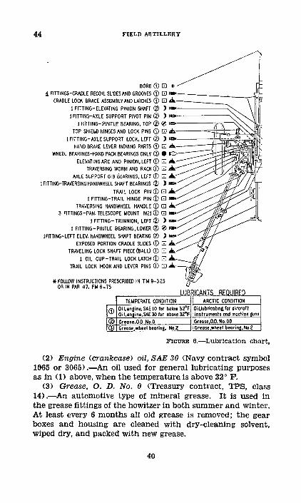
44 FIELD ARTILLERY
BORE 0 EO *_ FITTINGS-CRADLE RECOIL SLIDESAND GROOVES (0 0i a-
CRADLE LOCK BRACE ASSEMBLY AND LATCHES (0) [E A ,I FITTING-ELEVATING PINION SHAFT 0) ) l aIFITTING-AXLE SUPPORT PIVOT PIN (2 ) \\,
IFITTING-PINTLE BEARING, TOP (2) 0 \TOP SHIELD HINGES AND LOCK PINS (D0 E
I FITTING-AYLE SUPPORT LOCK. LEFT (2) )HAND BRAKE LEVER MOVING PARTS (D0
WHEEL BEARINGS-HAND PACK BEARINGS ONLY 90 6OELEVATING ARC AND PINION, LEFT (D - A.
TRAVERSING WORM AND RACK DO "/ AAXLE SUPPORT GIB BEARINGS. LEFT 0) 0d A
I FITTING-TRAVERSING HANDWHEEL SHAFT BEARINGS (2) )
TRAIL LOCK PIN 0() ]I FITTING-TRAIL HINGE PIN (1) 0 E f
TRAVERSING HANDWHEEL HANDLE 0(i E "/3 FITTINGS-PAN. TELESCOPE MOUNT M21() l a.
I FITTING-TRUNNION, LEFT (2 ) -///I FITTING-PINTLE BEARING, LOWER (0) 0 .
IFITTING-LEFT ELEV. HANDWHEEL SHAFT BEARING () ) 3 *
EXPOSED PORTION CRADLE SLIDES D [l A.TRAVELING LOCK SHAFT PIECE (BALL) () 0 A,
I OIL CUP-TRAIL LOCK LATCH 0(1) E A /TRAIL LOCK HOOK AND LEVER PINS El0 k
* FOLLOW INSTRUCTIONS PRESCRIBED IN TM 9-325OR IN PAR 47, FM 6-75
LUBRICANTS REQUIREDTEMPERATE CONDITION ARCTIC CONDITION
_ Oil.engine.SAE I0 for below 32°F Oillubricathntfor aircraftOilengne.SAE 30 for abov 3rF instruments end machine guns1D Grease.O D. No.O - GreaseO.D. No. O0
rrease,.el bearing. No 2 Grease,wheel bearing. No.2
FIGURE 6.-Lubrication chart,
(2) Engine (crankcase) oil, SAE 30 (Navy contract symbol
1065 or 3065).-An oil used for general lubricating purposes
as in (1) above, when the temperature is above 32°
F.
(3) Grease, 0. D. No. 0 (Treasury contract, TPS, class
14).-An automotive type of mineral grease. It is used in
the grease fittings of the howitzer in both summer and winter.
At least every 6 months all old grease is removed; the gear
boxes and housing are cleaned with dry-cleaning solvent,
wiped dry, and packed with new grease.
40
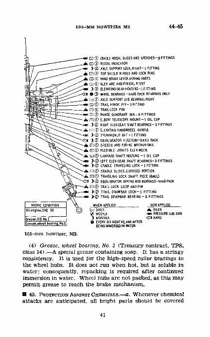
105-MM HOWITZER M2 44-45
Em ( ) CRADLE RECOIL SLIDES AND GROOVES-A FITTINGS
Al (D RECOIL INDICATOR. ), ® AXLE SUPPORT LOCK.RIGHT- I FITTING
a / TOP SHIELD HINGES AND LOCK PINS
El CD 0 HAND BRAKE LEVER MOVING PARTSA/ I /D ELEV. ARC AND PINION, RIGHT
f/ m ) ( ELEVATING GEAR HOUSING-1 FITTING
a ) ) WHEEL BEARINGS -HAND PACK BEARINGS ONLY
r- ] AXLE SUPPORT GIB BEARING,RIGHT.e El TRAIL HINGE PIN- I FITTINGa ( _D TRAIL LOCK PIN-.m_ El ID RANGE QUADRANT M4-6 FITTINGSa El () ELBOW TELESCOPE MOUNT-I OIL CUP-.m ) v RIGHT ELEV.GEAR SHAFT BEARINGS -3 FITTINGSA El OD ELEVATING HANDWHEEL HANDLE., ) ® TRUNNION,RIGHT-I FITTING
"- ) ) ®EQUILIBRATOR FULCRUM-HAND PACK
a El tD]BREECH AND FIRING MECHANISMS
A \ E D FLEXIBLE JOINTS ELEV.MECH.
A -. [(D LANYARD SHAFT HOUSING -1 OIL CUP
." m )" ® LEFT ELEV GEAR SHAFT BEARINGS- 2 FITTINGS\- )( CRADLE TRAVELING LOCK - FITTING
A El (D) CRADLE SLIDES, EXPOSED PORTIONa\ E1Q TRAVELING LOCK SHAFT PIECE (BALL)'E1 )(2 EQUILIBRATOR SPRING ROD BEARINGS-HAND PACK
.~ - Ad El (D) TRAIL LOCK LOOP AND PINv m )®C TRAIL DRAWBAR LOCK-1 FITTING
-e Z ) TRAIL DRAWBAR BEARING-2 FITTINGS
TROPIC CONDITION WHEN APPLIED HOWAPPLIEDOil.engine.SAE 30 [D DAILY. A OILER
0 WEEKLY. r - PRESSURE LUB.GUN
GreoseO.D.No.1 ) MONTHLY. S HANDGreose.wheel bearing,NO2 1 EVERY SIX MONTHS,AND AFTER
BEING IMMERSED IN WATER.
105-mm howitzer, M2.
(4) Grease, wheel bearing, No. 2 (Treasury contract, TPS,class 14).-A special grease containing soap. It has a stringyconsistency. It is used for the high-speed roller bearings inthe wheel hubs. It does not run when hot, but is soluble inwater; consequently, repacking is required after continuedimmersion in water. Wheel hubs are not packed, as this maypermit grease to reach the brake mechanism.
51 45. PROTECTION AGAINST CHEMICALS.-a. Whenever chemical
attacks are anticipated, all bright parts should be covered
41
45-46 FIELD ARTILLERY
with oil. After a gas attack, the oil is wiped off and fresh oilapplied. If mustard or other persistent gas is used, absorbentobjects may be deeply contaminated, and even hard surfacesmay be dangerous for from 6 to 8 days, if the chemical is notneutralized. Bleaching powder or chloride of lime and a non-corrosive decontaminating agent (a solution of either a lighttan or white powdery material in acetylene tetrachloride) arestandard. The noncorrosive agent will be used for the de-contamination of weapons when corrosion or other seriousdamage might result from the use of chloride of lime.
b. The noncorrosive decontaminating agent is sprayed onwith the hand-operated decontaminating apparatus. Thecontaminated surfaces should be given a number of light ap-plications of the spray at intervals of 15 to 30 minutes untilthe required amount of solution has been applied (see FM21-40). After all the solution has evaporated from thetreated surfaces, the mat6riel should be scrubbed, preferablywith soapy water, rinsed with clear water, and thoroughlydried. When appropriate, metal surfaces should then be oiledor greased to prevent corrosion.
c. Chloride of lime, if used, may be sprinkled on the mate-riel, painted on as a whitewash, or sprayed on with the hand-operated decontaminating apparatus. The application shouldnot be left on for more than an hour at most, after which thelime is washed off and the materiel rinsed thoroughly withWater.
d. All cleaning rags and sticks used in decontaminationmust be destroyed or otherwise disposed of to prevent dangerfrom subsequent handling. If destroyed by burning, caremust be taken to prevent contamination by dangerous vaporsproduced. If possible, the articles should be buried. In allcleaning operations, the gas mask and special gasproof glovesmust be worn.
[1 46. RECOIL MECHANISM.---a. General.-B a t t e r y mainte-nance of the recoil mechanism is limited to exterior cleaningand lubricating, draining and filling with recoil oil, remov-ing the recoil cylinder rear head, and disconnecting the pistonrod from the cradle. Whenever the barrel is removed, therecoil cylinder rear head should be removed in order to cleanthe rear interior of the recoil cylinder and to inspect for ex-cess oil leakage. At this time the rear head should be thor-
42
105-MM HOIWITZER M2 46
oughly cleaned and the relief valve should be lubricated andchecked for correct functioning. Only the heavy low-pour-point recoil oil as issued by the Ordnance Department may beused in the recoil mechanism. A full reserve of oil for the re-coil system amounts to approximately 11/2 fills of the screwfiller. In using the screw filler, care must be exercised to pre-vent crossing the threads or breaking off the end of the filler.The screw handle must be turned with both hands. Theamount of oil reserve in the system is shown by the position ofthe oil index with reference to the front face of the recupera-tor cylinder front head, as follows:
(1) No reserve.-The indicator is well into the recess. Thepiece must not be fired in this condition.
(2) Full reserve.-The end of the indicator is even with thefront face of the recuperator cylinder front head. The oil in-dex does not of itself show when there is an excess of oil re-serve, as the addition of excess oil does not move the indexout beyond the front face of the recuperator cylinder fronthead. The piece must not be fired with an excess reserve (seeb below).
b. Operations prior to firing.-(1) Before firing, the re-serve oil should be extracted until an insufficient reserve isindicated; then a full reserve should be established by insert-ing oil until the index is flush with the front face of therecuperator cylinder front head.
(2) The rear end of the recoil cylinder, the filling-and-drain-plug hole, and the oil index recess should be examinedfor oil leakage. The presence of a few drops of oil at any ofthese places is to be expected, but if there is an undue leakagethe piece must not be fired, and the condition should bereported to ordnance personnel.
c. Operations during firing.--(1) During firing, the recoilmechanism should be maintained at full reserve and theslides kept clean and properly lubricated.
(2) The chief of section should constantly verify the com-plete return of the piece to battery. Firing may be con-tinued as long as the piece returns to battery sufficiently forthe firing mechanism to actuate the trigger shaft.
(3) The chief of section should constantly observe the be-havior of the recoil mechanism in firing, and take such actionin the case of malfunctioning as is indicated below:
43
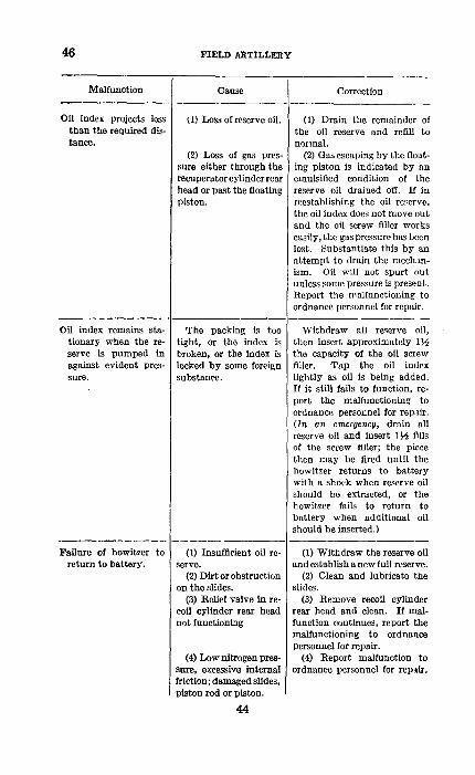
46 FIELD ARTILLERY
Malfunction Cause Correction
Oil index projects less (1) Loss of reserve oil. (1) Drain the remainder ofthan the required dis- the oil reserve and refill totance. normal.
(2) Loss of gas pres- (2) Gas escaping by the float-sure either through the ing piston is indicated by anrecuperatorcylinderrear emulsified condition of thehead or past the floating reserve oil drained off. If inpiston. reestablishing the oil reserve.
the oil index does not move outand the oil screw filler workseasily, the gas pressure has beenlost. Substantiate this by anattempt to drain the mechan-ism. Oil will not spurt outunless some pressure is present.Report the malfunctioning toordnance personnel for repair.
Oil index remains sta- The packing is too Withdraw all reserve oil,tionary when the re- tight, or the index is then insert approximately 1serve is pumped in broken, or the index is the capacity of the oil screwagainst evident pres- locked by some foreign filler. Tap the oil indexsure. substance. lightly as oil is being added.
If it still fails to function, re-port the malfunctioning toordnance personnel for repair.(In an emergency, drain allreserve oil and insert 1 ~ fillsof the screw filler; the piecethen may be fired until thehowitzer returns to batterywith a shock when reserve oilshould be extracted, or thehowitzer fails to return tobattery when additional oilshould be inserted.)
Failure of howitzer to (l) Insufficient oil re- (1) Withdraw the reserve oilreturn to battery. serve. and establish a new full reserve.
(2) Dirt or obstruction (2) Clean and lubricate theon the slides. slides.
(3) Relief valve in re- (3) Remove recoil cylindercoil cylinder rear head rear head and clean. If mal-not functioning function continues, report the
malfunctioning to ordnancepersonnel for repair.
(4) Low nitrogen pres- (4) Report malfunction tosure, excessive internal ordnance personnel for repair.friction; damaged slides,piston rod or piston.
44
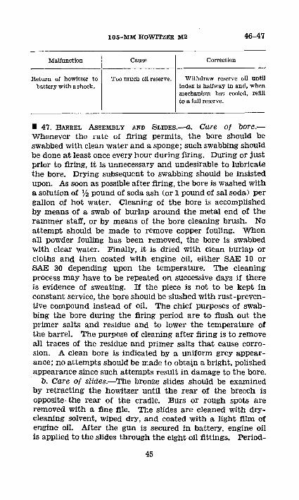
105-MMX HOWITZER M2 46-47
Malfunction Cause Correction
Return of howitzer to Too much oil reserve. Withdraw reserve oil untilbattery with a shock. index is halfway in and, when
mechanism has cooled, refillto a full reserve.
U 47. BARREL ASSEMBLY AND SLIDES.-a. Care of bore.-Whenever the rate of firing permits, the bore should beswabbed with clean water and a sponge; such swabbing shouldbe done at least once every hour during firing. During or justprior to firing, it is unnecessary and undesirable to lubricatethe bore. Drying subsequent to swabbing should be insistedupon. As soon as possible after firing, the bore is washed witha solution of l/2 pound of soda ash (or 1 pound of sal soda) pergallon of hot water. Cleaning of the bore is accomplishedby means of a swab of burlap around the metal end of therammer staff, or by means of the bore cleaning brush. Noattempt should be made to remove copper fouling. Whenall powder fouling has been removed, the bore is swabbedwith clear water. Finally, it is dried with clean burlap orcloths and then coated with engine oil, either SAE 10 orSAE 30 depending upon the temperature. The cleaningprocess may have to be repeated on successive days if thereis evidence of sweating. If the piece is not to be kept inconstant service, the bore should be slushed with rust-preven-tive compound instead of oil. The chief purposes of swab-bing the bore during the firing period are to flush out theprimer salts and residue and to lower the temperature ofthe barrel. The purpose of cleaning after firing is to removeall traces of the residue and primer salts that cause corro-sion. A clean bore is indicated by a uniform grey appear-ance; no attempts should be made to obtain a bright, polishedappearance since such attempts result in damage to the bore.
b. Care of slides.-The bronze slides should be examinedby retracting the howitzer until the rear of the breech isopposite. the rear of the cradle. Burs or rough spots areremoved with a fine file. The slides are cleaned with dry-cleaning solvent, wiped dry, and coated with a light film ofengine oil. After the gun is secured in battery, engine oilis applied to the slides through the eight oil fittings. Period-
45
47 FIELD ARTILLERY
ically, or at least every 2 weeks when in constant service, thehowitzer and sleigh should be removed from the cradle inorder to permit cleaning the entire length of the slides andthe interior of the cradle.
c. To retract howitzer.-The howitzer is retracted on itsslides as follows:
(1) Set the hand brakes.(2) Place the howitzer at approximately zero elevation
and lash the elevating handwheel to the right shield brace.(3) Remove the cotter pin and piston rod outer nut.(4) Push the howitzer and sleigh to the rear, being careful
that the howitzer and sleigh are not pushed so far to therear that the breech ring bearing strips lose contact with therear of the cradle.
d. To remove howitzer and sleigh.-To prevent damagingthe recoil mechanism, first the howitzer is removed and thenthe sleigh is removed. The procedure is as follows:
(1) Provide at least three heavy timbers and two ropeslings to support the howitzer in a horizontal position whenit is being removed.
(2) Set the hand brakes.(3) Remove the breechblock.(4) Place the howitzer at approximately zero elevation
and lash the elevating handwheel to the right shield brace.(5) Remove the locking screw in the recoil mechanism
bracket locking ring (barrel locking ring) and remove thering.
(6) Start the howitzer to the rear by striking the muzzlewith one of the lifting timbers or by means of a pinch barinserted between the front of the breech ring and the rearedge of the cradle trunnion bracket.
(7) Push the howitzer about 12 inches to the rear.(8) Using timbers and a rope sling, support the breech
and muzzle ends of the howitzer to avoid cramping, andcarry the howitzer to the rear. The third timber and a ropesling are used to support the middle of the howitzer as soonas the front end passes within the sleigh. Place the howitzeron wooden blocks or a suitable rest to prevent damage to thefinished surfaces and the bronze bearing strips in the bottomface of the breech ring.
(9) Remove the cotter pin and piston rod outer nut.
46
105-Ml. HOWITZER M2 47-48
(10) Four cannoneers working in pairs on opposite sidesof the carriage push the sleigh to the rear until it is freefrom the cradle, then lift it off and place it on wooden blocks.
e. To replace howitzer and sleigh.-The howitzer andsleigh are replaced by reversing the procedure of c or d above.The piston rod outer nut should be fully tightened and thenbacked off to the nearest castellation in order to permit sideplay without noticeable end play; it must not be drawn sotight that the inner nut is tight against the cradle. Thechief of section must verify before traveling and before firingthat the piston rod outer nut and its cotter pin are in place.
U 48. BREECH AND FIRING MECHANISMS.-a. General.-Sincethe breech and firing mechanisms consist entirely of un-painted and unprotected steel surfaces, the mechanisms aresubject to corrosion caused by powder fouling, rain, dirt, andmud. It is of particular importance that the moving ele-ments be kept well cleaned and lubricated. This can beaccomplished in only one way; that is, by a complete disas-sembly of all moving parts. The solution of water and sodaash (or sal soda) is used to remove the larger portion of thefouling. After the parts are rinsed with clear water anddried, any gummy residue remaining on them is removedwith dry-cleaning solvent. The mechanism is lubricatedwhile disassembled. It is important that the mechanism isthoroughly cleaned and dried before being lubricated, thatthe proper lubricant is selected, and that it is used in quan-tities sufficient only to reduce friction. In case of doubt asto the viscosity of oil to be used, especially when the pieceis to be fired, the lighter weight of oil should be selected.Constant checking is necessary to insure that cracked partsare replaced, and that burred parts are replaced or bursremoved. Hence, whenever the mechanism is disassembled,each part should be carefully inspected.
b. Disassembly of breech mechanism and firing lock.-To disassemble the breech mechanism-
(1) Raise the detent handle and remove the trigger shaft.(2) Open the breech to the point where the assembling
line on the top of the operating lever is parallel with the sideof the breech ring and lift out the operating-lever pivot.
(3) Slide the breechblock to the right, removing the oper-ating lever as soon as the crosshead clears the breech ring.
47
48 FIELD ARTILLERY
(4) Push the breechblock to the left to clear the extractorand remove the extractor from the breech ring.
(5) Remove the breechblock by pushing through to theright.
(6) Lay the breechblock on its lower face and remove tilhedetent spring retaining screw, spring, detent, and handle.
(7) Rotate the firing case 60 ° in either direction and pullit out of the breechblock.
(8) Pry the trigger fork out of the firing case with a screwdriver, first through the trigger shaft hole, then from theoutside of the case.
(9) Insert the trigger shaft to engage the yoke ends of thesear. Press the front end of the sear out of engagement withthe firing-pin holder, insert a, screw driver through the bottomhole and in rear of the firing-pin holder, and pry the assem-bled sleeve and holder forward until they can be grasped andpulled from the case.
(10) Remove the trigger shaft and shake out the sear andsear spring.
(11) Hold the front end of the firing-pin holder in onehand and place the lower rear end of the sleeve against theedge of a bench or some convenient part of the carriage.Push the firing-pin holder down to unhook it from the sleeve.Allow the holder to recede out of the sleeve, freeing the spring.
(12) Remove the cotter pin from the firing-pin holder, un-screw the firing-pin bushing, and remove the firing pin fromthe bushing.
(13) Unscrew the cross-head screw and remove the crosshead.
c. Assembly of breech and firing mechanisms.-The breechand firing mechanisms are assembled in the reverse order ofthe disassembly described in b above. However, the followingaids and precautions should be observed.
(1) The ends of the cotter pin in the firing-pin holdermust be spread so that they will not rub the firing case.
(2) The sear spring may be readily inserted into its seatby introducing the point of a screw driver between two coilsto hold the spring.
(3) The sear should be pressed down when the firing-pinholder is inserted in the case. This is easily done by insert-ing a screw driver through the front top hole of the firingcase.
48
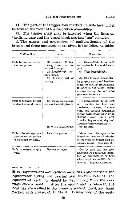
105-MM HOWITZER M2 48-49
(4) The part of the trigger fork marked "muzzle face" mustbe toward the front of the case when assembling.
(5) The trigger shaft may be inserted when the lines onthe firing case and the breechblock marked "top" coincide.
d. The causes and corrections of malfunctioning of thebreech and firing mechanisms are given in the following table:
Malfunction Cause Correction
Fails to fire; no percus- (1) Broken firing (1) Disassemble firing locksion on primer. spring; broken or de- and replace broken or deformed
formed firing pin. part.(2) Breechblock not (2) Close breechblock.
fully closed.(3) Howitzer out of (3) Check recoil mechanism
battery. for proper reserve and howitzerslides for dirt or obstructions.If cause is not found, reportmalfunctioning to ordnancepersonnel for repair.
Fails to fire until primer (1) Firing mechanism (1) Disassemble firing lockis struck several times. parts not working freely. and examine for burs and
roughened surfaces. Removeburs, and smooth roughenedsurface with crocus cloth or anoilstone. Wash parts withdry-cleaning solvent, dry andlubricate before reassembly.
(2) Weak firing spring. (2) Replace.
Fails to fire when proper Defective primer. Make three attempts to firepercussion on primer the primer, then wait 2 minutesis obtained (misfire), before opening breech and re-
moving round. (See par. 38.)
Fails to extract empty Broken extractor. Gently ram out the case.case. Examine the edge of the cham-
ber for deformations or burswhich might cause difficult ex-traction. Replace extractor.
* 49. EQUILIBRATOR.*-a. General.-To clean and lubricate theequilibrator spring rod bearing and fulcrum bearing, theequilibrator assembly should be dismounted from the car-riage once a month. After the equilibrator is removed, thebearings are washed in dry cleaning solvent, dried, and handpacked with grease, 0. D. No. 0. Disassembly of the equi-
49
49-51 FIELD ARTILLERY
librator is prohibited. There are no means provided foradjusting the equilibrator.
b. To remove.-The equilibrator is removed as follows:(1) Depress the piece to approximately zero elevation,
insert a 3- by 3- by 12-inch wood block between the frontspring seat and equilibrator fulcrum, and elevate the piece toremove the load from the springs.
(2) Remove the cotter pins, and force out the headlesspins from the equilibrator fulcrum. Depress the piece, low-ering the front end of the equilibrator to the ground. Pro-tect it from the dirt.
(3) Drive out the straight pin from the traveling lock(ball) piece on the right side of the cradle.
(4) Unscrew the ball piece.(5) Gently push the traveling lock shaft to the left, hold-
ing the equilibrator to prevent its falling, and remove theequilibrator assembly.
c. To mount.-Reverse the procedure of b above, notingthat the dust shields on either side of the equilibrator ful-crum bearing are in place.
* 50. ELEVATING MECHANISM AND CRADLE TRUNNION BEAR-INGs.-Disassembly, cleaning, and inspection of the elevatingmechanism and cradle trunnion bearings, and packing ofthe elevating mechanism gear housings will be done at theregular ordnance inspections.
* 51. WHEELS AND WHEEL BEARINGS.---a. General.-(1) The
care and maintenance of the wheel mechanism, includingtires, is a function of the battery. Tire pressure should bemaintained at 40 pounds. Tires should be removed at leastonce a year and the disk and rim cleaned and painted. Every6 months, or oftener if necessary, the wheel hubs should beremoved, the old grease flushed out, new grease pressed byhand into the space between the cleaned and dried rollersand race, and the wheel bearings adjusted. Best results areobtained if, after drying and before repacking, the rollerbearing is dipped into engine oil. Improper adjustment ofthe roller bearings will cause the rollers to be pitted orchipped. In general, a bearing chipped at the larger endindicates that the adjustment was too tight; a bearingchipped at the smaller end indicates too loose an adjustment.
50
105-MM HOWITZER M2 51
At all halts during marches, the chiefs of section or a desig-nated cannoneer should feel the wheel hubs for overheating.
(2) Overheating may be an indication of a tight bearing,faulty lubrication, or a dragging brake. The cause must bedetermined and correction made as directed by the officer incharge.
b. Disassembly.-To disassemble the wheel hub from thespindle-
(1) Remove the hub cap.(2) Remove the cotter pin, castellated nut, and washer
from the spindle.(3) Pull the hub from the spindle, being careful to pre-
vent the outer roller bearing from falling to the ground.c. Assemrbly and adjustment.-To assemble the wheel hub
on the spindle and to adjust the wheel bearings-(1) Clean and dry the bearings, dip the bearings in engine
oil, and fully pack with wheel-bearing grease. See that theinner bearing is properly in place; the oil retainer must notbear against the roller bearing. The hub cavity must not bepacked.
(2) Slide the wheel hub over the spindle, guiding the cupof the inner roller bearing over the cone and rollers and thebrake drum over the brake shoe.
(3) Slide the outer cone and roller on the spindle, andpress it firmly into its seat in the hub.
(4) Install the washer and nut, and adjust the bearing.To make this adjustment, the wheel should be rotated as theadjusting nut is being tightened. It is best to rotate thewheel in both directions, drawing up the nut until all thebearing parts are firmly seated. At this point a drag or re-sistance to rotation will be noted on the wheel. The nutshould now be backed off from one-sixth to one-quarter ofa turn. Now the wheel should rotate freely but without anyperceptible shake.
(5) Test the bearing adjustment by placing a short barbetween the tire and the ground, at the same time holdingone finger on the cage of the outer bearing. When, in work-ing the bar up and down, a barely perceptible movement isfelt and the wheel rotates freely when given a slight spin,the adjustment is correct. Insert the cotter pin and attachthe hub cap.
51
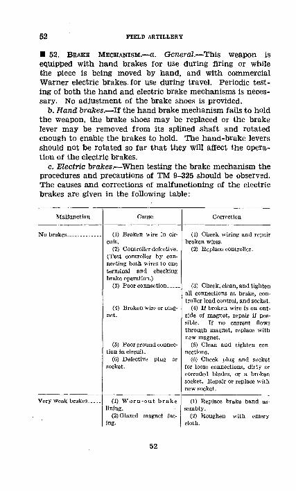
52 FIELD ARTILLERY
* 52. BRAKE MECHANISM.--C. General.-This weapon isequipped with hand brakes for use during firing or whilethe piece is being moved by hand, and with commercialWarner electric brakes.for use during travel. Periodic test-ing of both the hand and electric brake mechanisms is neces-sary. No adjustment of the brake shoes is provided.
b. Hand brakes.-If the hand brake mechanism fails to holdthe weapon, the brake shoes may be replaced or the brakelever may be removed from its splined shaft and rotatedenough to enable the brakes to hold. The hand-brake leversshould not be rotated so far that they will affect the opera-tion of the electric brakes.
c. Electric brakes.-When testing the brake mechanism theprocedures and precautions of TM 9-325 should be observed.The causes and corrections of malfunctioning of the electricbrakes are given in the following table:
Malfunction Cause Correction
No brakes ----------.. (1) Broken wire in cir- (1) Check wiring and repaircuit. broken wires.
(2) Controller defective. (2) Replace controller.(Test controller by con-necting both wires to oneterminal and checkingbrake operation.)
(3) Poor connection ---- (3) Check, clean, and tightenall connections at brake, con-troller load control, and socket.
(4) Broken wire or mag- (4) If broken wire is on out-net. side of magnet, repair if pos-
sible. If no current flowsthrough magnet, replace withnew magnet.
(6) Poor ground connec- (5) Clean and tighten contion in circuit. nections.
(6) Defective plug or (6) Check plug and socketsocket. for loose connections, dirty or
corroded blades, or a brokensocket. Repair or replace withnew socket.
Very weak brakes (1) Worn-out brake (1) Replace brake band as-lining. sembly.
(2)Glazed magnet fac- (2) Roughen with emerying. cloth.
52
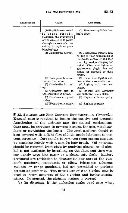
105-MM HOWITZER M2 52-53
Malfunction Cause Correction
(3) Stoplights connected (3) Remove stop lights fromin brake circuit. brake circuit.(Changes the graduationof the current as it passesthrough the controller, re-sulting in weak or grab-bing brakes.)
(4) Insufficient current. (4) Insufficient current maybe due to poor connections atthe brake, controller and loadcontrol ground, or the plug andsocket. Clean and tighten allconnections; check plug andsocket for corroded or dirtyblades.
(5) Poor ground connee- (5) Clean and tighten con-tion at the brakes. tacts at the brake and frame.
(6) Controllerburned (6) Replace with new con-out. troller.
(7) Contactor arm in (7) Smooth out contactorthe controller is pitted. arm with fine emery cloth.
(8) Broken magnet (8) Replacewithnewspring.spring.
(9) Wornwheelbearings. (9) Replace bearings.
U 53. SIGHTING AND FIRE-CONTROL EQUIPMENT.-a. GeneraL-
Especial care is required to insure the positive and accuratefunctioning of the sighting and fire-control mechanisms.Care must be exercised to prevent denting the soft metal sur-faces or scratching the lenses. The steel surfaces should bekept covered with a light film of high-grade lubricant to pre-vent corrosion. Dirt should be removed from optical surfacesby brushingi lightly with a camel's hair brush. Oil or greaseshould be removed from glass by applying alcohol or, if alco-hol is not available, by breathing on the glass and then wip-ing lightly with lens paper or a clean, soft cloth. Batterypersonnel are forbidden to disassemble any part of the gun-ner's quadrant, panoramic or elbow telescopes, telescopemounts, or range quadrant, but are permitted to performcertain adjustments. The procedures of c to f below may beused to insure accuracy of the sighting and laying mecha-nisms. In general, the sighting system is correct-
(1) In direction, if the deflection scales read zero when
53
53 FIELD ARTILLERY
the line of sighting is in a plane parallel to the vertical planepassing through the axis of the bore.
(2) In elevation-(a) If, with the elevation scales of the panoramic tele-
scope set at zero and with the elevation indexes of the mountin coincidence, the line of sighting through the zero rangeline of the telescope is parallel to the axis of the bore.
(b) If the algebraic sum of the "site" and "elevation" settingIndicates the same angle above the horizontal that is meas-ured with an accurate gunner's quadrant on the tube.
(3) If there is no excessive lost motion between the sightsand the tube.
b. Testing equipment.-Equipment used in testing sightsconsists of bore sights and a gunner's quadrant. Tools neededfor adjustments are a screw driver and a teat-wrench. Thetarget for bore sighting may be a terrain object more than1,000 yards away, or a test target. When the test target isused, the displacement of the axis of sighting from the axisof the bore must be correctly shown. For this howitzer thedisplacement of the panoramic telescope is 15.23 inches to theleft of and 10.61 inches above the axis of the bore, and the dis-placement of the elbow telescope is 13.375 inches to the rightof and 8.375 inches above the axis of the bore. Aiming postswith wooden blocks or markers attached make a suitable testtarget. Tests can be made without the bore sights by sight-ing through the firing lock recess in the breechblock orthrough a brass cartridge case with the primer removed,using improvised cross hairs at the muzzle.
c. Gunner's quadrant.-(1) End-for-end test.-(a) Setboth the graduated arc and index arm (sliding level) scalesat zero, and tighten the clamp screw.
(b) Place the quadrant on the leveling plates of the howitzerand center the bubble, using either elevating handwheel ofthe piece.
(c) Reverse the quadrant on the leveling plates. Thebubble should recenter itself. If it does not, change the set-ings until the bubble is centered and take the reading. Inthe case of a minus correction it will be necessary to set thegraduated arc scale one notch below zero, and move the slid-ing level initially to the opposite end of the index arm. Thecorrection (the setting to be used in getting a true horizontal)is one-half of the displacement measured, in the same sign.
54
105-MM HOWITZER M2 53
If the necessary correction exceeds 0.3 mil, the quadrantshould be adjusted by ordnance personnel at the earliestopportunity.
(2) Index arm test.-Set a reading of any multiple of 10on the quadrant and place the sliding level at zero. Level thebubble by means of either elevating handwheel of the piece.Move the index arm one notch down, and slide the level vialto the opposite end of the scale. The bubble should remaincentered.
(3) Comparison test.-Successively place the five quadrantsof the battery on the leveling plates of a piece which is laidat any selected elevation. Repeat the same process for severalother elevations and list the reading of each quadrant at eachelevation. Determine a mean correction for each quadrantand apply this as a correction constant. If any quadrantexceeds an error of 0.3 mil it should be adjusted by ordnancepersonnel at the earliest opportunity.
d. Rapid daily test.-The on-carriage fire-control equip-ment is rapidly checked for correct adjustment in the fol-lowing manner:
(1) The chief of section sets the gunner's quadrant at zero,places it on the leveling plates, and No. 1 levels the piece.
(2) No. 1 sets the angle-of-site scales at 300 and centersthe cross-level and angle-of-site bubbles. The elevationscales should read zero. (The range drum will not readexactly zero due to the allowance for jump.)
(3) The gunner centers the longitudinal and cross-levelbubbles of the telescope mount. The elevation indexes shouldbe in coincidence.
(4) Nos. 1 and 2 install the bore sights and, if necessary,set up the testing target. The gunner lays the piece by boresighting on the testing target or distant terrain object.
(5) The gunner lays the center vertical cross hair and thezero horizontal cross hair of the telescope reticule on theproper portion of the test target. If the telescope is in ad-justment the azimuth and elevation scales and their respec-tive micrometer scales will indicate zero deflection and eleva-tion.
(6) No. 1, by observation, restores the range lines in thereticule of the elbow telescope to the horizontal with the erect-ing knob. The N (normal) cross hair of the reticule shouldbe on the appropriate line of the test target.
55
53 FIELD ARTILLERY
(7) If the foregoing tests indicate that some portion ofthe mechanism is out of adjustment, it should be adjustedby following the procedure outlined in c above and f and gbelow, or a correction should be determined, written on someconvenient location such as the shield, and used until thereis an opportunity to adjust the faulty mechanism.
e. Verification and adjustment of the telescope mount andthe panoramic telescope.-Periodically, and whenever themechanism is found to be out of adjustment, a detailed testand adjustment should be made. For this purpose it is de-sirable to have the howitzer on an approximately level plat-form or the howitzer trunnions level. It is assumed that alllost motion has been eliminated and that cross-level bubblesare in adjustment. (For details see TM 9-325.) Tests andadjustments are performed in sequence as follows:
(1) Elevation indexes of telescope mount.-Lay the how-itzer at zero elevation with the gunner's quadrant and centerthe cross-level and longitudinal-level bubbles. The elevationindexes should coincide; if they do not, loosen the two screwsin the adjustable index and slide it into coincidence with thefixed index. Tighten the screws and recheck.
(2) Deflection and range scales of the panoramic tele-scope.-Bore sight on the test target or a distant terrainobject. Insure that the elevation indexes of the telescopemount are in coincidence. Using the appropriate knobs ofthe telescope, place the center vertical cross hair and zerohorizontal cross hair of the telescope reticule on the properportion of the test target. If the azimuth and elevationscales and their respective micrometer scales do not indicatezero deflection and elevation, adjust in the following manner:
(a) Deflection adjustment.-Turn the azimuth worm knobof the telescope until the center vertical cross hair is on theappropriate line of the test target. Loosen the screw in thecenter of the azimuth micrometer index and, while holdingthe azimuth worm knob, slip the index until it correspondswith the deflection index. Tighten the screw and recheck.This adjustment must not be made by moving the headlessadjusting screws in the telescope socket. If necessary, themain azimuth scale should also be adjusted to zero.
(b) Elevation adjustment.-Turn the elevating knob ofthe telescope until the zero horizontal cross hair of the reti-cule corresponds with the appropriate mark of the testing
56
105-MM HOWITZER M2 53
target. Loosen the screws in the end of the knob and, holdingthe knob, slip the elevation micrometer until the zero gradua-tion lines up with its index; then tighten the screws andrecheck the setting.
/. Verification and adjustment of range quadrant.-(1)Move the range drum assembly indexes into coincidence. Theelevation micrometer scale and the elevation scale shouldread zero. The range drum will indicate a reading slightlygreater than zero if properly assembled.
(2) With the range drum properly assembled, if the eleva-tion micrometer scale does not read zero, it is adjusted in thefollowing manner:
(a) Loosen the three screws in the micrometer knob.(b) Without moving the knob, slide the zero of the mi-
crometer scale into coincidence with the index.(c) Tighten and recheck.(3) With the elevation micrometer scale in adjustment, if
the elevation scale does not indicate zero, it is adjusted inthe following manner:
(a) Loosen the two screws in the index. Move the indexopposite the zero graduation.
(b) Move the index into coincidence with the zero gradua-tion.
(c) Tighten the screws and recheck.(4) With the elevation micrometer scale and the elevation
scale in adjustment and set at zero, the trunnions and theaxis of the bore are accurately leveled, the angle of site isset at 300, and the cross-level bubble is centered. If thelongitudinal-level bubble is not centered, the range quadrantis adjusted in the following manner:
(a) Center the longitudinal bubble by means of the angle-of-site knob.
(b) While holding the angle-of-site knob, loosen the clamp-ing screw in the meter of the knob and slip the angle-of-site micrometer to indicate zero. Tighten the clamping screw.
(c) If necessary, loosen the two screws which secure theangle-of-site scale and shift the scale so that the "3" gradua-tion registers at the index line. Tighten the screws to securethe scale in this position.
(d) Recheck. Further adjustment, if required, is to beperformed only by authorized ordnance personnel.
57
53 FIELD ARTILLERY
g. Verification and adjustment of the elbow telescope andits mount.-With the axis of the trunnions leveled, bore sighton the test target. By observation, correct the reticule tothe horizontal by means of the erecting knob. If the N crosshair is not on its line of the test target, put it on in the fol-lowing manner:
(1) Loosen the worm clamping bolt.(2) With a screw driver, move the elevating adjusting
worm to bring the N cross hair in coincidence with the properline of the target.
(3) Tighten the worm clamping bolt.(4) Recheck.
0
58