Embed Size (px)
Citation preview
MHI Copy 3 FM 6-40
WAR DEPARTMENT
FIELD ARTILLERY FIELD MANUAL
FIRING
Report Documentation Page Form ApprovedOMB No. 0704-0188
Public reporting burden for the collection of information is estimated to average 1 hour per response, including the time for reviewing instructions, searching existing data sources, gathering andmaintaining the data needed, and completing and reviewing the collection of information. Send comments regarding this burden estimate or any other aspect of this collection of information,including suggestions for reducing this burden, to Washington Headquarters Services, Directorate for Information Operations and Reports, 1215 Jefferson Davis Highway, Suite 1204, ArlingtonVA 22202-4302. Respondents should be aware that notwithstanding any other provision of law, no person shall be subject to a penalty for failing to comply with a collection of information if itdoes not display a currently valid OMB control number.
1. REPORT DATE OCT 1939 2. REPORT TYPE
3. DATES COVERED 00-00-1939 to 00-00-1939
4. TITLE AND SUBTITLE Field Artillery Field Manual, Firing
5a. CONTRACT NUMBER
5b. GRANT NUMBER
5c. PROGRAM ELEMENT NUMBER
6. AUTHOR(S) 5d. PROJECT NUMBER
5e. TASK NUMBER
5f. WORK UNIT NUMBER
7. PERFORMING ORGANIZATION NAME(S) AND ADDRESS(ES) Department of the Army,101 Army Pentagon,Washington,DC,20310
8. PERFORMING ORGANIZATIONREPORT NUMBER
9. SPONSORING/MONITORING AGENCY NAME(S) AND ADDRESS(ES) 10. SPONSOR/MONITOR’S ACRONYM(S)
11. SPONSOR/MONITOR’S REPORT NUMBER(S)
12. DISTRIBUTION/AVAILABILITY STATEMENT Approved for public release; distribution unlimited
13. SUPPLEMENTARY NOTES
14. ABSTRACT
15. SUBJECT TERMS
16. SECURITY CLASSIFICATION OF: 17. LIMITATION OF ABSTRACT Same as
Report (SAR)
18. NUMBEROF PAGES
202
19a. NAME OFRESPONSIBLE PERSON
a. REPORT unclassified
b. ABSTRACT unclassified
c. THIS PAGE unclassified
Standard Form 298 (Rev. 8-98) Prescribed by ANSI Std Z39-18

FM 6-40
FIELD ARTILLERY FIELD MANUAL
FIRING
Prepared under direction of the Chief of Field Artillery
UNITED STATES
GOVERNMENT PRINTING OFFICE
WASHINGTON: 1939
For sale by the Superintendent of Documents, Washington, D. C. Price 25 cents
WAR DEPARTMENT, WASHINGTON, October 10, 1939.
FM 6-40, Field Artillery Field Manual, Firing, is published for the information and guidance of all concerned.
[A. G. 062.U (7-14-39) .]
BY ORDER OF THE SECRETARY OF WAR:
OFFICIAL:
E. S. ADAMS, Major General,
G. C. MARSHALL, Chief of Staff.
The Adjutant General.
II

TABLE OF CONTENTS
CHAPTER 1. THE FIRING BATTERY,
Section I. General-------------------------Paragraphs Pages
1- 7 1- 3 11. Precautions In firing ____________ _ 8- 12 3- 6
III. Posts and duties ________________ _ 13- 24 6- 10 IV. Organization of the position _____ _ 25-- 38 10- 16 V. Fire commands and their execu
tion___________________________ 39- 76 VI. Examples of fire commands_______ 77- 79
CHAPTER 2. ELEMENTARY BALLISTICS AND DISPER-SION, AND EFFECTS OF PROJECTILES.
Section I. Elementary- ballistics and dispersion--------------------------- 80-- 85
II. Effect of project!les______________ 86- 89 CHAPTER 3. PREPARATION OF FIRE.
Section 1. General------------------------- 9{}- 94 II. Preparation of fire with instru
ments------------------------- 95--109 III. Firing charts _____________________ 11{}-114 IV. Survey operations, plans, and pro-
cedure _________________________ 115--122 V. Preparation of fire from firing
charts------------------------- 123-133 VI. Schedule fires ____________________ 134-142
CHAPTER 4. CoNDUCT oF FIRE.
Section I. General------------------------- 143-147 II. Attack of targets _________________ 148-151
III. AxiaL--------------------------- 152-156 :(V. LateraL _________________________ 157L-164 V. Combined----------------------- 1651-170
VI. Adjustment with sound-and-flash ·unfits __________________________ 171~174
VII. Conduct of fire with air observation_-------------------------- 175--186
VIII. Conduct of fire by air observation methods, using ground observers-1){. Smoke __________________________ _
X. Gas-----------------------------CHAPTER 5. TEcHNIQUE OF FIRE DIRECTION.
Section I. General-------------------------11. support by observed fires ________ _
III. Schedule fir'es ___________________ _ IV. Ammunition requirements _______ _
187-190 191-194 195--196
197~201 202-203 204-207 208-212
CHAPTER 6. DEAD SPACE, VIsmiLITY, AND CALmRATION----------------------------- 213-215
CHAPTER 7. SERVICE PRACTICE-------------------- 216-225 INDEX-------------------------------------------------
III
16- 35 35-- 40
41- 48 49- 52
53- 54
54- 68 68- 74
74- 87
87- 99 99-120
121-123 123-125 126-135 135-146 147-152
153-154.
154-162
163-165 165--167 167-169
170-173 173-177 177-180 180-182
182-187 187-190 191-198
FM 6-40
FIELD ARTILLERY FIELD MANUAL
FIRING
(The matter contained herein supersedes TR 430-85, September 2, 1930 (including 01, January 2, 1932); and Parts One and Six, Volume II, Field Artillery Field Manual, December 28, 1931.)
CHAPTER 1
THE FIRING BATTERY Paragraphs
SECTION I. General-------------------------------- 1- 7 IT. Precautions in firing____________________ 8-12
nr. Posts and duties------------------------ 13-24 IV. Organization of the position _____________ 25-38 V. Fire commands and their execution ______ 39-76
VI. Examples of fire commands-------------- 77-79
SECTION I
GENERAL
• 1. ScoPE.-This chapter covers duties of personnel of the firing battery <except those duties prescribed for the service of the piece) and prescribes fire commands with explanation of their execution. It governs primarily the division artillery, but with obvious modifications applies to all types and calibers.
• 2. TERMS usEo.-a. Firing battery, as used in this manual, includes only that portion of a gun or howitzer battery at the firing position, carriages unlimbered or uncoupled and prepared for action.
b. Battery commander, as used in this manual, refers to the officer commanding the battery or conducting the fire of the battery.
c. Fire discipline is that condition, resulting from training and practice, which insures the orderly and efficient functioning of personnel in the delivery of fire. The basis of
1
FIRING
fire discipline is the thorough training of the individual soldier.
• 3. TaAINING.--a. The object of training is the perfection of fire discipline throughout the firing battery as a whole. Training includes instruction in the care, preservation, description, and nomenclature of materiel; the acquirement of a knowledge of the duties of all cannoneers in the squad by each member thereof, and a thorough understanding of fire command; and the development of manual dexterity and teamwork in the mechanical operations involved. The executive is charged with this traininl~.
b. Gun squad. training is the preliminary phase of training in fire discipline; firing battery instruction is the advanced phase. Training of the firing battery should be started shortly after instruction of gun squads is begun.
c. Firing battery instruction is started in the gun park. As proficiency is gained, the training advances to varied terrain and simulated service conditions. Occupation and organization of position under varied conditions, including darkness and bad weather, should be practiced. Fire on targets is first simulated, followed by subcaliber and service practice.
d. Each batterY should maintain a minimum of four trained gun squads. Individuals of special aptitude should be assigned appropriately to permanent positions, but at drills posts should be changed frequently in order to develop flexibility and permit the ready replacement of absentees or casualties.
e. During maneuver or campaign as well as during the training year, frequent drill of the firing battery is necessary to maintain a high standard of fire discipline. However, during actual firing, while correction of errors is necessary, instruction in the service of the piece will be avoided since it interferes with the effective deliverY of fire .
• 4. ACCURACY AND SPEED.-Accuracy in the performance Of individual duties must be stressed; it is obtained by insistence upon exactness from the beginning. Speed acquired by prompt performance of individual duties in regular sequence must not be stressed at the expense of accuracy
2
FIRING 5-9
• 5. LosT MoTION.-To eliminate the effects of lost motion, settings must be made in a uniform manner as prescribed for the particular piece or instrument concerned.
• 6. CHECKING.-a. Frequent checks of setting and laying are necessary to insure accuracy, both at drill and during firing. Checking during firing is usually restricted to lulls in action, except that when firing close to friendly troops constant checking by the executive and assistant executive is indispensable. It must be made with an absolute minimum of delay in firing.
b. When a piece is discovered to have fired with an error in laying, the error is corrected and reported immediately to the battery commander. When a piece is plainly and unaccountably in error, firing with it ceases and it is reported out of action until the error is found and corrected.
• 7. UNIFORMITY.-Uniformity is necessary both in giving and in executing commands. However, while instruction always should conform to the spirit and principles of this manual, latitude is allowed in the practical application thereof, and subordinates are encouraged to use their skill and ingenuity in solving the problems which occur in service.
SECTION II
PRECAUTIONS IN FIRING
• 8. REFERENCE.-8pecial measures peculiar to a particular weapon will be found in the pertinent manual of the FM 6-series for the Service of the Piece.
• 9. CARE OF MATERIEL.-a. As soon as practicable after artillery materiel has been used, it is cleaned and put in order under the supervision of an officer. Lost or unserviceable parts are replaced or repaired. The work is not complete until everything is again ready for immediate service.
b. Before the piece begins firing, the chief of section verifies that the recoil mechanism contains the proper amount of liquid; thereafter he carefully observes the functioning of the recoil system.
3
9-10 FIRING
c. In the case of separate-loading ammunition, the powder chamber is swabbed out after each round to extingUish sparks. During :firing, a pail of water is kept under each piece and the bore is washed whenever fire is suspended for a short time. Usually it is sufficient to wash the bore forward a distance of 2 feet from the breech for light and medium and 6 feet for heavy artillery.
d. During prolonged firing, it is d~;irable to rest each piece at least 5 minutes of each hour.
e. When time permits during suspension of fire, the breechblock is dismounted, cleaned, and oiled, and the bore cleaned as prescribed in •rechnical Regulations for the materiel.
t. Permissible rates of fire for short bursts (up to 10 minutes) and for prolOnged fire are given in FM 6-130; these· rates are exceeded only if the situation demands it.
B 10. CARE OF AMMUNITION.-Ammunition is sorted and stored by lots. When received boxed or crated, it is kept packed as long as practicable; after it iH unpacked, it is protected from dirt and ground moisture by being placed on paulins or raised off the ground. Each lot is covered by a paulin or other material to protect it from rain and sun and to keep the temperature uniform throughout that particular lot. The paulin or other covering should be raised to allow free circulation of air.
a. Projectiles.--Unpacked projectiles and complete rounds are piled. Piles or groups are located 10 or more yards apart and contain not more than one hundred rounds of 75-mm ammunition, fifty 155-mm projectiles, or twenty-five 240-mm projectiles. When piled, the height will not exceed five layers for 75-mm ammunition and three layers for 155-mm projectiles. Planks or brush are pletced between layers. Projectiles of 240-mm caliber are never piled but may be laid horizontally. Care is taken to prevent :injury to the rotating bands; they are always examined before firing and any burrs removed with a file. Chemical shell are piled at a distance from the battery, in a direction downwind· from the prevailing wind, and are inspected frequently for leakage. Adapter plugs are lett in projectiles until immediately before the fuzes
4
FIRING 10-11
are to be inserted, ana the projectiles are not fuzed until immediately before they are to be fired.
b. Powder charges.-It is especially necessary that powder charges be kept dry and ventilated. They are kept in moisture-proof containers until just before use. Powder charges are so stored as to reduce the possibility of their ignition in case of a flare-back or other accident at the piece.
c. Fuzes and primers.-Fuzes and primers are kept dry and stored separately from the other components of the ammunition. They are not carrfed on the person. Primers are especially sensitive to shock. Fuzes are seated securely <screwed home with the fuze wrench issued for that purpose) before firing. If difficulty is encountered in screwing home a fuze or if a fuze is otherwise defective, it is laid aside temporarily and at a convenient time it is buried 3 feet deep or turned over at the position to ordnance personnel if available. Before returning ammunition to a vehicle or container, a careful check is made to insure that the combination fuzes are set at safety and that other types of fuzes are removed from projectiles and properly stored or disposed of otherwise. The precautions to be taken in the use of any particular type of fuze are given in the Technical Regulations pertaining to the materiel.
d. Misfires.--See the FM 6-series for the Service of the Piece .
• 11. UNLOADING A PIECE.--a. Unloading fixed ammunition or projectiles is to be avoided whenever possible. If unloading a piece becomes necessary, in case the projectile cannot be extracted readily or becomes separated from the cartridge case when the breech is opened, it is removed under the direct supervision of an officer, using a rammer which bears only on the projectile and provides for clearance around the fuze.
b. When unloading fixed ammunition, the breech is opened very slo,wly to reduce the likelihood of separating the cartridge case from the projectile and of scattering loose powder from the propelling charge inside the breech. Should the cartridge case separate from the projectile, the piece is brought to the horizontal and the breech recess cleaned to
5
11-14 FIRING
remove the loose powder. When the rammer is used, the recess in the ·rammer head is inspected to insure that it is free from foreign matter. Projectiles being removed should be prevented from falling to the ground when forced to the rear .
• 12. PRECAUTIONS IN HANDLING AMMUNJTION.-The following precautions also are observed:
a. Ammunition is not tossed, rolled, or dropped. b. Smoking in the vicinity of explosives is prohibited; care
is taken to avoid sparks or open flames nearby. c. A round of ammunition held in preparation for reload
ing the piece is kept free from the path of recoil. d. Tampering with or disassembling any component of a
round is prohibited. e. Any ammunition exposed to gas is wiped off immediately
with an oiled rag. !. Personnel handling chemical projectiles are provided
with gas masks and gloves. g, All rounds are examined before loading. h. With pieces using separate· loading animunition, prim
ers are not inserted until after the breechblock is closed and locked in its recess.
i. When the long lanyard is used, it will not be attached until the piece is otherwise ready to fire.
i. Pieces are examined before firing is begun to insure that their safety features are in order and that the bores are clear.
SECTION Ill
POSTS AND DUTIJ!:S
• 13. GENERAL.-Individuals at the firing battery are dismounted; they are not restricted to posts designated herein when their duties require their presence elsewhere.
• 14. ExECUTIVE:s.-The post of the executive is a position near the pieces from which he can best supervise the firing battery and be in communication with the battery commander. He should be able to see all the pieces and be seen
6
FIRING 14-16
by the chiefs of section, and his voice must be heard distinctly by all cannoneers. His principal duties are to--
a. Establish the firing battery in position. b. Organize the position. c. Comply with the fire commands of the battery com
mander.
• 15 AssiSTANT ExEcuTIVE.-The post of the assistant. executive when at the firing battery is in the vicinity of the pieces where he can best perform his duties. His principal duties when at the firing battery are to-
a. Assist the executive and to act as executive in the latter's absence.
b. Supervise and check the work of gun squads .
• 16. CHIEF OF PIECE SECTION.-The chief of a piece section goes where he can control the service of his piece, hear commands, and perform his duties effectively. A convenient post is 2 yards from the end of the trail on the side opposite the executive. His duties are-
a. To place the piece in position, to announce to his gun squad its number in battery, to measure and announce the minimum elevation <or range), and to enforce camouflage and gas defense discipline.
·b. To identify and point out to the gunner the aiining point, the referring point, or the target.
c. To follow fire commands, but to repeat only such part as may be called for by a member of his squad.
d. For direct laying in which his section is used, to assign a part of the target to his gunner. <See the pertinent manual of the FM 6-series for the Service of the Piece.)
e. For indirect laying, to indicate the general direction to be given the piece and to operate the gunner's quadrant when used.
f. To show that his piece is ready to fire by extending hls right arm vertically as soon as his gunner calls "Ready."
g. Except when otherwise prescribed, to give the command FIRE, dropping his arm sharply to his side.
h. To execute prearranged fire when a written schedule for it is furnished him.
7
16-17 FIRING
i. To supervise and check the work of the gun squad and to report to the executive errors discovered in the laying; for example, "No. 1 fired 5 mils right."
j. To report when the piece is out of ~ction and the reason therefor; for example, "No. 1 (or so and so) out, must dig trail trench deeper to reach that range."
k. To conduct the fire of his section in fire at will and at other times when so directed.
l. During firing·, to watch the recoil system and measure the length of reeoil. To ascertain by inspection that the recoil cylinder contains the proper amount of liquid and that the pressure in the counterrecoil system is correct.
m. To have the section ammunition properly handled, cared for, and stored by lot, and the materiel and equipment cleaned as prescribed.
n. To keep the data for the gun book and data pertaining to his piece.
o. To apply calibration corrections to his piece when and as prescribed by the battery commander.
p, To enforce strict compliance with safety precautions .
• 17. AMMuNITION SERGEANT OR CoRPORAI •. -Tbe battery cOlnmander will designate an ammunition sergeant or corporal. His post is at the, battery ammunition dump, if there is one; otherwise, in the vicinity of the post of the executifle. His duties are to--
a. Have charge of such ammunition at the position as is not issued to the sections.
b. Receive, inspect, sort, and care for ammunition not delivered directly to sections.
c. Issue ammunition to piece sections, dividing each lot equally among them.
d. Keep accurate records, by lot, of all ammunition issued to the battery, tabUlating receipts, issues, and expenditures; prepare ammunition reports.
e. Keep the executive informed as to the amount and kinds of ammunition on hand.
t. Dispose of ammunition left at positions, making the necessary reports.
8
FIRING 18-22
• 18. TELEPHONE OPERATOR.-The teiephone operator is usually seated in rear of the battery and toward the windward flank. His duties are to-
a. Have charge of and operate all telephone communication at the position.
b. Have ample slack wire left at the battery and to see that the wire is not damaged during the occupation of position.
c. Establish communication promptly and report to the executive, "Communication established." To report to the executive when communication is out.
• 19. LINEMEN.-Linemen at the position of the firing battery· are with, and under the command of, the telephone operator.
• 20. REcORDER.-The battery commander designates a recorder. The recorder is seated beside the telephone operator. His duties are to-
a. Record all fire commands and messages. b. Tabulate his record so that he can instantly give the
executive the setting for any piece. c. Record the minimum elevation (or range) and the base
deflections. d. Keep a file of fire schedules.
• 21. CHIEF MEcHANic.-The chief mechanic normally is at the battery position. His duties are to-
a. Inspect materiel, observe the functioning of the pieces, and make such repairs as can be made properly at the position.
b. Assist the ammunition sergeant.
• 22. SENTINELs.--,Sentinels are posted as the executive may direct. Their duties are as follows:
a. Sentinels at pieces.-To alert gun squads, report unusual events, prevent pieces from being disturbed, and, upon the signal for firing the normal barrage, to load and fire the pieces until relieved.
b. Gas sentinels.-To keep gas alarms in serviceable condition, to be on the alert to discover gas, to sound the alarm, and to give assistance in gas defense.
9
22-25 FIRING
c. Circulation sentinels.-To enforce orders with respect to movement of individuals, animals, and vehicles in or near the position.
d. Rocket sentinels.-To distinguish pyrotechnic signals; to operate rocket boards; to call, "Barrage" immediately upon seeing the barrage signal; and to report other signals in accordance with his orders.
e. Security sentinels.-To prevent surprise, to assist in defense, and to direct and guide authorized persons to the battery position .
• 23. REPLACEMENT OF CASUALTIES.-During action, casualties are replaced as follows: the executive, by the senior present; the assistant executive, not replaced; chief of piece section, by the gunner <who continues to act as gunner also); gunners and cannoneers, by redistribution of duties by the chief of section or by the executive if necessary; others, as the executive may direct. Permanent assignments and reassignments are made by the battery commander as appropriate. Casualties are reported to higher authority daily or at such times as called for .
• 24. RESUPPLY OF AMMUNITION.-Under the direction of the battery commander, the executive, assisted by the ammunition sergeant, supervises the ammunition supply, As the necessity for resupply is foreseen, the battery commander requests the necessary amounts and types from the battalion. The battery commander makes a daily ammunition report to the battalion.
SECTION IV
ORGANIZATION OF THE POSITION
• 25. DEFINITION.-Organization of the position is the systematic performance at the firing battery position of all functions which contribute to the prompt opening and delivery of accurate fire and to the concealment and protection of personnel, materiel, and ammunition. Organization begins when the position is selected and is continuous through occupancy.
10
FIRING 26-28
• 26. ORDER IN BATTERY.-All carriages are unlimbered or uncoupled and prepared for action. The pieces may be placed in line at regular intervals or they may be placed irregularly, in which case they are said to be "staggered." The pieces of a battery when staggered should not be so separated as to preclude the direct control, by the executive, of the firing battery as a whole. When the pieces are in line and the interval between muzzles is 20 yards, they are said to be at "normal'' intervals. Pieces in position are designated from right to left as No. 1, No. 2, No. 3, and No. 4, without regard to the permanent numerical designations of sections .
• 27. OccUPATION OF POSITION.---a. When a position is OCcupied after dark or positions have been selected for each individual piece, the executive designates to each chief of section the position for his piece and the direction of fire. Each chief of section conducts his section individually to the position designated.
b. Where practicable, in order to avoid a multiplicity of tracks, the position is occupied from the march formation. The position is approached from a fiank in section column. When opposite the piece positions, the trucks or carriages are halted in the track made by the leading vehicle or carriage; the pieces and caissons are uncoupled or unlimbered and run into position by the cannoneers; trucks are unloaded; and the trucks or limbers are then moved on past the position, leaving a single track passing the position.
c. The executive checks communication at the battery and posts the telephone operator at the position from which he will normally give commands .
• 28. LAYING THE BATTERY FOR DIRECTION.-The executive lays the battery as commanded by the battery commander, or, if no commands have been received, lays it parallel in the direction indicated by the gun marker. In the latter case, if no aiming point or compass has been indicated, he should lay on a definite Y-azimuth (par. 55) usually a multiple of 100 mils.
11

29-30 FIRING
• 29. REFERRING PIEcEs.--a. To refer a piece which has been laid for direction, an aiming point is announced and the deflection is measured and recorded. The command for referring is, for example:
AIMING POINT, AIMING STAKES. REFER,
b. A common aiming point used for referring should be fixed, continuously visible, and as distant from the battery as possible. It should contain a clearly defined vertical line or a definite point on which the gunners can lay.
c. When a common aiming point is used, aiming stakes should be set up (for emergency use) at such a time as does not interfere with the firing. When a common aiming point is not used, the executive orders the aiming stakes set up as soon as the position is occupied. The command is: AIMING STAKES OUT.
d. Two aimin~r stakes are used for each piece. One stake is set up at a convenient location at least 100 yards from the piece; the other stake is set up at the midpoint between the first stake and the piece. Both stakes are set up so that they and the sight of the piece are on the same straight line. Whenever aiming stakes are used, the pieces are also referred to an auxiliary aiming point which is used in case the aiming stakes are knocked down during firing. During darkness, a light is attached to each aiming stake, the near light lower than the far light. Each light is completely screened except for a narrow vertical slit visible through the sight .
• 30. DISPLACEMENT CoRRECTIONS.--a. 'When a gunner sees that his aiming stakes are out of line, he notifies the chief of section <who notifies the executive) and uses the far stake for laying until the piece can be moved or a correction is authorized by the executive. The correction is made by the gunner who--
<1) Lays on the far stake. (2) Refers to the near stake. (3) Lays on the far stake with the new reading. (4) Realines the stakes <as soon as practicable) by mov
ing the near stake.
12
FIRING 30--32
b. Lateral displacement is most likely to occur when the axle of the piece is not level. This is particularly true of materiel equipped with pneumatic tires. Lateral displacement may be prevented by placing sandbags against the outside of each wheel. When gun platforms are used, wheel guides are constructed .
• 31. DETERMINING PIECE INTERVALS.-If the pieces are Staggered, the executive determines the interval from No. 1 to each of the other pieces by measuring or pacing the distance· from No. 1 along a line perpendicular to the line of fire to points opposite each of the other pieces. These intervals are recorded and used for forming the sheaf as explained in paragraph 62.
8 32. DETERMINING MINIMUM RANGE OR ELEVATION.-a. As SOOn as each piece is established in position and laid in the direction indicated by the gun marker, the executive causes the minimum range or elevation tp be measured.
(1) Mi:nimum rarnge is used only in the hasty occupation of a position and when the range to the mask does not exceed 600 yards. In such case, the executive selects the greatest minimum range setting reported to him by the chiefs of section, adds thereto the range in yards from gun to crest of mask, and reports the sum to the battery commander; for example, "Minimum range 1,600 <or so much)." Site zero <or 300) is used in determining the minimum range setting unless otherwise ordered. The foregoing is a rapid methOd providing a satisfactory safety factor for clearing an unoccupied crest.
(2) Minimum elevation is used in all cases except the above. The executive-
(a) Selects the greatest minimum elevation reported bY the chiefs of section.
(b) Adds thereto the elevation (from Firing Tables) for the piece-mask range for the type of available ammunition having the lowest velocity.
(c) Adds two forks at the piece-mask range <from Firing Tables).
(d) If the mask is occupied by friendly troops, adds the value in mils of a height of 5 yards at the piece-mask range.
177568'--39----2 13
32--35 FIRING
<e> Reports the sum to the battery commander as the minimum elevation.
b. The battery commander normally will advise the executive as to the probable sector of fire and require a report as to the minimum elevation throughout the sector. A few probable eritical points can be selected readily by Inspection and the minimum elevations determined for them. In this way, accidents will be avoided in instances where the mask is very irregular. The executive may be required to determine mi.Dimum elevation for a particular projectile, charge, and fuze; further, he may be required to determine rt for each piece.
c. Pieces are not fired at a quadrant elevation less than the minimum elevation or that corresponding to the minimum range setting and site as determined by the executive. If a fire command includes an elevation (or range) less than the minimum elevation (Or range), the executive reports to the battery commander, "Minimum elevation <so much)" or "Minimum range (so much) ."
• 33. OPENING FIRE.--a. When the above operations have been completed, the executive reports to the battery commander, "Battery ready."
b. If complete fire commands are received before these operations have been completed and if it is obviously safe to fire, the opening of fire takes precedence.
c. Further steps in the organization of position are completed as rapidly as possible provided they do not interfere with the fire .
• 34. IMPROVING EMPLACEMENTS.-As time permits, SUCh of the following improvements are carried out as are appropriate for the type of materiel: construction of trail trenches, backed by trail logs; leveling of the ground occupied by the pieces; and construction of wheel platforms or firing-base ·supports .
• 35. DEFENSIVE MEASURES (F'M 6-20) .-a. References.Chapters 1 and~~. Engineer Field Manual, Volume IT; Chapter 8, Basic Field Manual, Volume I.
b. Concealment.-Pbsitions should be concealed from en'emy ground and air observation. To thi.s end, the movement
14
FIRING 35-37
into position should be concealed, pieces irregularly emplaced, camouflage correctly employed, circulation controlled, and the use of lights and fires restricted. Measures for concealment must not delay preparations for promptly opening fire.
c. Protection.-The position must be prepared for defense against artillery fire and direct attack by ground troops and aircraft. Passive means, such as camouflage, cover, and concealment, are used. Active defensive means comprise the fire of small anns and of the pieces themselves. Construction work must harmonize with the camouflage scheme and ordinarily be executed at night.
d. Gas dejense.-Orders for gas defense should cover such of the foJiowing as are appropriate: location, use, operation, and maintenance of gas alarms; adjustment, removal, and care of gas masks; reporting of gas attacks and of their termination; defensive measures; assistance for casualties; and protection of material objects. All personnel must be instructed in defensive measures and selected individuals taught gas protection.
• 36. RELIEFs.-During long-continued action, personnel is divided into reliefs. Sentinels are posted at the pieces when the latter are not actually firing, the remainder of each gun crew being allowed to rest in sheltered positions near by.
• 37. RECORDs.--a. The following records are kept; (1) Each chief of piece section keeps a notebook and data
for the gun book. In the notebook he keeps data of semipermanent value to his piece, such as calibration corrections, base deftection, and data for defensive fires. The data for the gun book are the number of rounds fired, defects, repairs, and similar pertinent information.
(2) Each gunner records, on data boards set up for each piece when necessary, base deflection, calibration corrections when appropriate, minimum range or elevation, and data for primary defensive fire missions. Base deflection and minimum range or elevation are also entered on the shield of pieces equipped therewith.
(3) Each cannoneer operating a fuze setter keeps, when appropriate, calibration corrections for the fuze setter.
15
37-40 FIRING
(4) The ammunition sergeant keeps a record by lot of all ammunition at the position, consisting of a tabulation of receipts, issues, and expenditures, and reports of ammunition expenditures. The ammunition report is prepared from this record.
(5) The recorder keeps a record of all fire commands, reports, and messages as prescribed in paragraph 20.
b. Extract copites of fire missions or fire schedules may be furnished by the battery commander to each chief of piece section and complete copies to the recorder. All schedules are carefully preserved.
c. Except as prescribed no records of fire commands are made .
• 38. EVACUA'!'ION' OF CASUALTIES.-Firing is not interrupted because of casualties. Available first aid is administered immediately. The slightly wounded walk to battalion aid stations; others, including gas cases, are removed by litter or ambulance at appropriate times.
SECTION V
FIRE COlVlMANDS AND THEIR. EXECUTION
• 39. DEFINITIONS.---a. Fire commands are commands which convey all the information necessary for the commencement, conduct, suspension, and cessation of fire, and activities incident thereto.
b. Firing data are the elements of a fire commanP. which prescribe the settings of instruments and fuzes in the firing battery.
c. The base piece is the piece <usually No. 1) for which initial data are computed and with reference to which data for other pieces 1tre found .
• 40. ORIGIN AND TRANSMISSION.-Fire commands originate with the battery commander. They are sent to the firing battery by telephone, radio, signal flags, signal lamp, voice relay, or messenger. The executive repeats the commands of the battery commander to the gun squads, except as noted herein.
16
FIRING 41-44
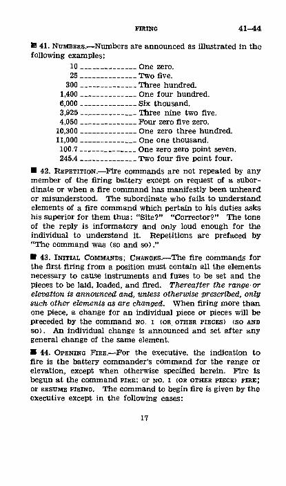
I! 41. NUMBERs.-Numbers are announced as illustrated in the following examples:
10 --------------One zero. 25 --------------Two five.
300 --------------Three hundred. 1,400 --------------One four hundred. 6,000 --------------Six thousand. 3,925 --------------Three nine two five. 4,050 --------------Four zero five zero.
10,300 --------------One zero three hundred. 11,000 -------------- One one thousand. 100.7 --------------One zero zero point seven. 245.4 --------------Two four five point four.
• 42. REPETITION.-Fire commands are not repeated by any member of the firing battery except on request of a subordinate or when a fire command has manifestly been unheard or misunderstood. The subordinate who fails to understand elements of a fire command which pertain to his duties asks his superior for them thus: "Site?" "Corrector?" The tone of the reply is informatory and only loud enough for the individual to understand it. Repetitions are prefaced by "The command was (so and so)."
• 43. INITIAL COMMANDS; CHANGES.-The fire commands for the first firing from a position must contain all the elements necessary to cause instruments and fuzes to be set and the pieces to be laid, loaded, and fired. Thereafter the range· or elevation is announced and, unless otherwise prescribed, only such other elements as are changed. When firing more than one piece, a change for an individual piece or pieces will be preceded by the COmmand NO. 1 (OR OTHER PIECES) (SO AND
so>. An individual change is announced and set after any general change of the same element.
• 44. OPENING F'IRE.-For the executive, the indication to fire is the battery commander's command for the range or elevation, except when otherwise specified herein. Fire is begun at the command FIRE; or NO. 1 (OR OTHER PIECE) FIRE; or RESUME FIRING. The command to begin fire is given by the executive except in the following cases:
17

44-48 FIRING
a. By the chief of section during schedule fire and in fire at will.
b. By the gunner during fire at moving targets with direct laying. (See the pertinent manual in the FM 6-series for the Service of the Piece.>
• 45. CEASING F'IRE.-Fire is stopped by the executive's command CEASE FIRING or SUSPEND FIRING, but in emergencieS anyone present may give the command CEASE FIRING. Fire always is stopped at the command CEASE FIRING, whatever its source. When a piece has been loaded with HE shell and the command CEASE FIRING has been given, the executive reports to the battery commander, "No. 1 (or other pieces) loaded," and acts on the instructions received.
• 46. SusPENDING AND RESUMING F'IRE.-The command susPEND FIRING is used when the battery is firing on a schedule and a temporary stop is desired. The pieces are left loaded and the laying conforms to the schedule. When fire may be delayed more than a minute, the battery commander should command: UNLOAD. At the command RESUME FIRING, fire is resumed in accordance with the schedule .
• 47. SIGNALS.-The commands FIRE and CEASE FffiiNG USUally are given by arm signals as well as by voice. The signal for FIRE is to drop the right arm from a vertical position sharply to the side or to point with the right hand at the piece to be fired, extend the arm vertically and drop it sharply to the side. The signal for CEASE FIRING is to raise both arms vertically and hold them in that position until the signal is understood by all concerned, or to give one long whistle blast .
• 48. PIECES To FOLLOW COMMANDS.-{t. A fire command will be followed by all pieces unless it includes NO. <so AND so> ADJUST. This command may be given as the first element of the fire command or may follow any other element of the command except the range or elevation.
b. At the command NO. (SO AND SO) ADJUST, only those pieces specified follow the subsequent commands.
c. To require the pieces that have not been following to fOllOW, BATTERY ADJUST, Or RIGHT (LEFT) ADJUST, is giVen as
18
FIRING 48-51
the first element of a subsequent fire command, which, in prescribed sequence, will include appropriate data for such pieces and the designation of pieces to fire and the method of fire.
• 49. SEQUENCE.-:!.. The prescribed sequence of fire commands is:
(1) Special methods of adjustment and particular mis-sions.
(2) Direction. (3) Converging sheaf. (4) Deflection difference. (5) Site. (6) Projectile. (7) Charge. (8) Fuze. (9) Fuze range or time. 00 > Pieces to fire. (11) Method of fire. (12) Use or discontinuance of use of quadrant. (13) Range or elevation. b. The commands for ceasing and suspending fire may be
given at any appropriate place in the sequence. When the command REFER is to be used as an element of a fire command, it follows the announcement of the aiming point. The COmmand RECORD BASE DEFLECTION When used with REFER follows REFER; otherwise it may follow the commands for laying for direction; it is usua-lly the last element announced .
• 50. CoMMANDS FOR SPECIAL ADJUSTMENTS AND MISSIONS.Appropriate types are: ON NO. (SO AND SO> ADJUST SHEAF PARALLEL; INSTRUMENT DIRECTION, RIGHT (LEFT) (SO MUCH>; or LAY ON NORMAL BARRAGE, or (ON SO AND SO>. The first two are not repeated verbatim to the gun squads •
• 51. INITIAL DIRECTION.-The battery commander may direct the initial laying of the battery for direction by commanding: A TARGET AND A DEFLECTION; AN AIMING POINTED AND A DEFLECTION; A ¥-AZIMUTH; or A BASE ANGLE.
19
52-55 FmiNG
• 52. CHANGES IN DIRECTION.-After the battery has been laid for direction initially, the battery commander announces changes in direction by commanding: RIGHT <LEFT> <SO MUCH), or BASE DEFLECTION RIGHT <LEFT> <SO MUCH) , or by any of the means listed in paragraph 51. Base deff,ection is a recorded deflection setting by which the pieces of the battery are laid parallel and in a known direction .
• 53. TARGET.-The command is: TARGET (SO AND SO), followed by a deflection. It is an order to use direct laying. Each gunner is assigned his part of the target by his chief of section; the latter also corrects the direction of his piece during firing .
• 54. AIMING POINT AND DEFLECTION.-The battery commander commands: AIMING POINT <SO AND SO); DEFLECTION <SO MUCH), or PLATEAU <SO MUCH) DRUM <SO MUCH>. When the aiming point is not visible from all pieces of the battery, the executive may set the announced deflection on an aiming circle, sight on the aiming point, u·sing the lower motion, and lay the battery as described in paragraph 57.
• 55. Y-AZIMUTH.-The battery commander commands: COMPASS <SO MUCH). The executive does not repeat this command. He lays the battery with either a prismatic compass or an aiming circle. The instrument should be at least 30 yards from any masses of metal which might deflect the needle. The steel helmet and other metal objects should be removed from the vicinity of the instrument.
a. With the prismatic compass.-The executive determines the compass reading to the target by subtracting the declination constant of his prismatic compass from the announced Y -azimuth, adding 6,400 if necessary. He then places himself at least 60 yards in rear of the base piece and at a position such that the compass reading of the line from his instrument to the sight of the base piece is approximately the compass reading determined as above. He holds the compass to his eye and gives the following command to the gunner: AIMING POINT, THIS INSTRUMENT, DEFLECTION ZERO, or PLATEAU 0 DRUM 100.
20
FIRING 55-56
The execution of this command lays the piece on the prolongation of the line: Executive-base piece. The executive measures the compass reading of this line by reading to the sight of the piece. He then determines the difference between this compass reading and the desired compass reading and commands a shift of this amount to lay the piece on the desired azimuth. The remaining pieces are laid parallel by reciprocal laying on the base piece (par. 58).
b. With the aiming, circle.-The instrument is set up at least 60 yards from the nearest piece and in such a position that it is suitable as an aiming point for all pieces. The executive lays the 0-3,200 line of the aiming circle on the announced Y -azimuth as follows:
(1) French aiming circle.-(a) He subtracts the announced Y-azimuth from the declination constant of the aiming circle (adding 6,400 to the declination constant if necessary).
(b) He sets the remainder on the azimuth and micrometer scales of the aiming circle.
(a) He releases the compass needle and centers it with the lower motion. After clamping the needle, he lays each piece reciprocally on the aiming circle (par. 57).
(2) American aiming circle, M1916.-(a) He measures the magnetic azimuth to the base piece and to this magnetic azimuth adds the declination constant of his aiming circle.
(b) He subtracts the announced Y-azimuth from this sum (adding 3,200 if necessary). The result is the firing angle for the base piece, using the aiming circle as an aiming point.
(c) He commands: AIMING POINT, THIS INSTRUMENT NO. 1 (base piece), DEFLECTION <SO MUCH) <as determined in (b) above).
(d) He then sets this announced deflection on his aiming circle and lays on the base piece.
(e) He then lays the other pieces reciprocally on the aiming circle (par. 57).
• 56. BAsE ANGLE.-a. The battery commander commands, for example: BASE ANGLE 1,800. The executive does not repeat this command.
b. If the orienting line runs through the sight of the base piece, the executive commands, for example: AIMING
21
56-58 FIRING
POINT, THAT S'J:'AKE (or other aiming point on the orienting line), DEFLECTION 1,800. The remaining pieces are laid parallel to the base piece by any convenient method.
c. If the orienting line does not run through the sight of the base piece, the executive sets up the aiming circle for use as an aiming point at a suitable point on the orienting line, lays the 0-3,200 line of the aiming circle in the proper direction by setting the base angle (1,800) on the azimuth scale and laying the instrument along the orienting line with the lower motion. He then lays each piece reciprocally on the aiming circle (par. 57). ·
• 57. LAYING PARALLEL WITH AIMING CIRCLE.-The aiming circle is set up in a position suitable for use as an aiming point and the 0-:3,200 line is established in the proper direction as described in paragraphs 54, 55 b, and 56. The executive, by means of the upper motion, directs the instrument on the sights in turn, determining and announcing the deflection for each piece from the readings on the aiming circle. When guns with French sights are being laid with the French aiming circle, the plateau and drum readings are taken directly from the aiming circle. With panoramic sights, 3,200 mils must be subtracted from readings which exceed 3,200. The executive commands, for example: AIMING POINT, THIS INSTRUMENT, DEFLECTION NO. 1, 3091; NO. 2, 2738; NO. 3, 23159; NO. 4, 2045. When time permits, the operation is repeated at the command of the executive until the same readings are obtained on two successive trials. The executive then commands, for example:
AIMING POINT, AIMING STAKES. REFER.
Each gunner refers and announces the referred deflection for his piece.
8 58. LAYING PARALLEL BY RECIPROCAL l,AYING.-This method should be considered only an emergency means of forming a parallel sheaf for use when an aiming circle is not available.
a. The base piece having been laid for direction, the executive may command, for example: ON NO.1 LAY PARALLEL.
b. All pieces are brought to the horizontal after setting site zero (300), range zero; pieces other than the base piece
22
FmiNG 58-61
are traversed to their centers and by shifting trails are pointed approximately parallel to the base piece. The gunner of the base piece refers in turn to the sights of the other pieces and announces the deflection reading of each, for example: "No. 2, 1580; No. 3, 1560; No. 4, 1550."
c. Each gunner sets as deflection the reading announced for his piece, and using the sight of the base piece as the aiming point, lays for direction; the chief of section reports, "No. (so and so) ready." When time permits, the operation is repeated at the command of the executive until the same readings are obtained on two successive trials.
d. When the pieces have been laid, the executive announces an aiming point and causes the pieces to be referred .
• 59. LAYING PARALLEL BY USE OF A COMMON AIMING POINT.-When the pieces are using a common distant aiming point and are in line at regular intervals, the executive may form a parallel sheaf by means of a deflection and a deflection difference. The deflection announced is that of the base piece. The deflection difference is determined by measuring or estimating the interval between two adjacent pieces perpendicular to the direction of the aiming point and dividing by the distance to the aiming point in thousands of yards. The deflection difierence is open if the aiming point is in front; close, if in rear .
• 60. DIRECTION ESTABLISHED BY ONE PlECE.-After establishing the direction for the base piece, the battery commander may cause the others to be laid parallel by the command: ON NO. 1 (or other piece) FORM SHEAF PARALLEL. The executive does not repeat this command. He forms a parallel sheaf by reciprocal laying; by having the base piece referred to the aiming circle, laYing the aiming circle reciprocally on the sight of the base piece, and then laying the remaining pieces parallel with the aiming circle; or by the use of a common aiming point and a deflection difference .
• 61. DEFLECTION DIFFERENCE.~. If the battery commander desires to control distribution directly, following a command for direction he announces a command for deflection dif-
23

61-62 FIRING
ference; for example: ON NO. 1 (or other piece) OPEN <CLOSE) <SO MUCH).
b. If the battery commander desires to control distribution indirectly through the executive, he will give a command for convergence (par. 62) followed by a deflection difference to obtain the desired width of sheaf; for example: CONVERGE AT 3,000, ON NO.1 OPEN 8 .
• 62. CONVERGING THE SHEAF.--a. The command given by the battery commander is: CONVERGE AT <SO MUCH>. The executive does not repeat this command. He causes the sheaf to be formed parallel by any one of the methods described in paragraphs 57, 58, and 59. He then determines the individual corrections to converge Nos. 2, 3, and 4 on No. 1 at the range announced by the battery commander, and gives the commands necessary to accomplish this convergence. When the pieces are at regular intervals, this may be effected by a command for deflection difference; "for example: ON NO. 1 CLOSE <SO MUCH>.
b. On occupation of position, the executive may prepare a convergence table as follows: He measures the distance in yards between pieces, normal to the direction in which he expects to fire, and, by the mil relation, computes the convergence at ranges which may be fired. He tabulates these results. The following table is convenient in determining the individual shifts for convergence; the values are given in mils.
Interval from No. 1 (yards)
Range
100 90 80 70 00 50 40 30 20 10 5 --------------------
1,500_ ----- 67 (iQ 53 47 40 33 'Z7 20 13 7 3 2,000 _______ 50 45 40 35 30 25 20 1.5 10 5 3 2,500 ______ 40 a6 32 28 24 20 16 12 8 4 2 3,000 ______ 33 ao 'Z7 23 20 17 13 10 7 3 2 3,500 ______ 29 ~!6 23 20 17 14 11 9 6 3- 1 4,000 ______ 25 :!3 20 18 15 13 10 8 5 2 1 4,500 ______ 22 ~m 18 16 13 11 9 7 4 2 1 5,000_ ----- 20 18 16 14 12 10 8 6 4 2 1 5,500 ______ 18 16 15 13 11 9 7 5 4 2 1 6,000 ______ 17 15 13 12 10 8 7 5 3 2 1 7,000 ______ 14 13 11 10 9 7 6 4 3 1 1 8,000 ______ 13 11 10 9 8 6 5 4 3 1 1 9,000 ______ 11 10 9 8 7 6 4 3 2 1 1 10,000_-- -- 10 9 8 7 6 5 4 3 2 1 1
24

FIRING 63-66
• 63. ANGLE OF SITE.-For the 75-mm gun, French, Ml897, the command is: SITE PLUS (MINUS) <SO MUCH), or SITE ZERO; for other pieces: SITE 305 or <SO MUCH). The site is not announced when using the gunner's quadrant, and, with some types of materiel, when using direct laying.
• 64. PROJECTILE.-The command for shell is: SHELL MK. I <or other type designation); the use of shrapnel is directed by the command for corrector setting.
• 65. CHARGE.-a. For charges termed normal, reduced, or supercharge, the charge is designated in a fire command only when other than the normal charge is to be used. In such case, the command is: REDUCED CHARGE or SUPERCHARGE. When a change is to be made from either of the two above charges to the normal charge, the command is: NORMAL CHARGE.
b. For numbered charges the command is: CHARGE I or <SO MUCH).
• 66. FuzE.-a. When usir:g shell <except time sheiD, the command for the fuze is; FUZE QUICK <DELAY>.
b. When using shrapnel <or time shell), the command for a corrector setting is: CORRECTOR <SO MUCH); for a change in the corre1::tor setting: UP <DOWN) <SO MUCH); for percussion fire: PERCUSSION. When the fuze setter is graduated for corrector and time, the commands are: CORRECTOR <SO MUCH) ; TIME <SO MUCH) , changes being indicated by a corrector change or a new time setting. When the battery has both time shell and shrapnel available, the use of shrapnel is directed by the command SHRAPNEL, given before the command CORRECTOR (SO MUCH) .
c. When using fuze setters graduated for corrector and range, the fuze range is the same as the range setting unless otherwise announced. When a fuze range other than the piece range is to be used, the fuze range is announced thus: "Fuze range (so much)." When firing with the range drum, the fuze range is announced whenever it differs from the piece range. When pieces are laid at an elevation rather than at a range setting, the fuze range is announced initially; thereafter, whenever changed.
25
67-68 FIRING
• 67. PIECES To 1"'RE.-a. To fire the battery, the command is: BATTERY. To fire one platoon, the command is: RIGHT <LEFT), indicating the right <left) platoon. To fire any other eombination of pieces, the command is: NUMBER(S) (SO AND SO). The command FIRE AT WILL
directs all pieces to fire. b. When a change in pieces to fire or the method of fire,
or both, is to be made, the commands for both elements are given. Decreasing or increasing the number of rounds in a methOd of fire does not constitute a change of method.
• 68. METHODS oF F'IRE.-The methods of fire are salvo fire, volley fire, volley fire sweeping, continuous ftre, by piece at my command, fire at will.
a. Salvo fire.-The command is: RIGHT (LEFT), and indicates the flank from which pieces are to be fired successively. Fire is opened at the executive's command FIRE, pieces being fired at the command of chiefs of section, in order from the right Oeft), at intervals of 2 seconds. The interval of 2 seeonds may be changed by adding AT <so MANY) SECONDs. This interval will be used until the method is changed or another interval announced. The executive gives the command FIRE when he sees that the pieces are ready to fire. If one or more pieces are apparently in error or are very slow, they are called out and. the remaining pieces fired.
b. Volley fire.--The command is: <SO MANY) ROUNDS. Fire is opened at the executive's command FIRE, given immediately after the range or elevation.. Each piece to be fired fires the specified number of rounds as rapidly as is consistent with accuracy without regard to other pieces, each round being fired at the command of the chief of section, NO. <so AND so> FIRE. There are three exceptions to the above, as follows:
(1) When firing at a moving target witll direct laying, the announcement of the range is the authority to fire; each piece is fired at the command of the gunner. (See the pertinent manual in the FM 6-series for the· Service of the Piece.)
(2) When safety regulations require personnel to take cover, the designated pieces fire simultaneously at the execu-
26
FIRING 68
tive's command, which is given when the pieces are ready to fire and cover has been taken.
(3) When the battery commander prescribes a time interval during the firing of a single piece; for example, 3 ROUNDS AT 10 sEcoNDs. Each round is fired at the executive's command.
c. Volley fire, sweeping.-(!) Normal sweeping.-The command is: <SO MANY) ROUNDS SWEEPING (RIGHT), (SO MANY) TURNS <MILS). Fire is opened and executed as prescribed for volley fire, except that after each round the gunner traverses the piece the number of turns of the handwheel or the number of mils specified in the command. The sweep is always to the left unless RIGHT is included in the command. When the last round of the sweep has been fired, the gunner traverses the piece back to the original laying.
(2) Cross sweeping.-The command is: <SO MANY) ROUNDS CROSS SWEEPING, <SO MANY) TURNS <MILS). The execution is the same as for normal sweeping, except that even-numbered pieces sweep to the right.
d. Continuous fire.-The command is: CONTINUOUS FIRE RIGHT <LEFT) AT (SO MANY) SECONDS. If fire is by a single piece, RIGHT (LEFT) is omitted and AT SO MANY SECONDS may be omitted, in which case the piece is fired as rapidly as it can be laid accurately. Continuous fire, when executed by more than one piece, is a succession of salvos, the pieces being fired consecutively at the interval designated in the command. The fire is continued until the method of fire is changed or until the command CEASE FIRING is given. Changes of data are applied so as not to stop the fire or break its continuity.
e. By piece at my command.-To fire each piece individually at his command, the battery commander commands: BY PIECE AT MY COMMAND. When the battery is ready to fire, the executive reports to the battery commander, "Battery is ready," and, when the battery commander's command to fire is received, commands, for example: NUMBER (SO AND SO) FIRE.
f. Fire at will.-The command is: TARGET <SO AND SO), FIRE AT WILL. Tllis method is used for firing at a target
27

68-71 FIRING
attacking or about to attack the battery. Direct laying is employed. The laying is as prescribed in the pertinent manual of the FM 6-series for the Service of the Piece. Without further command from the executive or the battery commander, each piece opens fire at the command of the chief of section and fires as rapidly as possible until the command CEASE FIRING is given,
• 69. HoLDING E'IRE.----4. If the battery c,ommander does not desire the pieces to be loaded, he commands: DO NOT LOAD before announcing the range or elevation. To begin fire after the command DO NOT LOAD, the battery commander commands the range or elevation.
b. If the battery commander desires the pieces to be loaded but the opening of fire to be held, he commands: AT MY COMMAND before announcing the range or elevation .. The command is not repeated by the executive. When the pieces are ready to fire, the executive reports, "Battery is ready." To begin firing, the battery commander commands: FffiE, which is repeated by the executive. AT MY coMMAND continues in effect until a method of fire is announced not followed by AT MY COMMAND.
• 70. GUNNER's QUADRANT.-The command to use or discontinue using the gunner's quadrant is announced immediately before the range or elevation. The command is: QUADRANT or WITHOUT QUADRANT .
• 71. RANGE OR ELEVATION.--a. The COmmand for range iS the announcement of the range setting, as, "4,800"; for elevation' the elevation setting, as, "140.6." When firing more than one piece and the pieces are laid at different elevations, and in this case only, the command SAME ELEVATION may be used.
b. The command for the executive to fire a series of ranges in a definite sequence is ZONE, followed by the range bound (if other than 100 yards) and the limiting ranges. For example: ZONE, 4,800, 4,600; or ZONE 200, 2,200, 2,600. The executive does not repeat the command but gives commands to fire at the following ranges: the first range announced, and ranges differing by 100 yards or by the amount of the range bound announced, until the final limiting range
28
FIRING 71-72
is reached; then ranges halfway between those fired in the reverse order. The ranges fired for the first command given above are 4,800, 4,700, 4,600, 4,650, 4,750. For zone fire using elevations, the command must include the elevation bounds as well as the limiting elevations; in other respects the procedure is similar. For example: ZONE 6 MILS, <QUADRANT) 148, 160; the elevations fired are 148, 154, 160, 157, and 151.
c. If it is desired to fire through a zone two or more times, appropriate commands are repeated as necessary.
d. The command for the range or elevation always is given in each series of fire commands when it is intended that pieces be loaded and fired.
• 72. ScHEDULE F'IRES.-a:. Written data for concentrations and standing barrages usually are sent to the executive by command sheet. The arrangement of entries on this sheet is such that the executive can announce his commands in proper order by reading from it. Frequently, however, the executive will find it necessary to furnish each chief of section written data for each mission to be fired on a time schedule. Data for a rolling barrage are furnished by the battery commander on section data sheets to the chiefs of section, who are individually responsible for announcing-data and giving the commands to fire according to the schedule.
b. The number of rounds to be fired is determined from the method of fire, zone and range <elevation) commands, and appropriate entries in the "Remarks" column of the command sheet. When time limits are shown for missions other than a rolling barrage, the executive causes the fire to start at the designated time. These time limits simply require that the missions be completed within the specified time without restricting the executive as to the rate of fire.
c. The normal barrage may be started by the piece sentinels (par. 22) or at the executive's command BARRAGE. Complete data, including rates of fire and duration, for all standing barrages should be furnished each chief of section. Sufficient ammunition for several complete barrages is stored in a place convenient for prompt use. One round is always kept ready for immediate loading. When not engaged in firing, the battery is kept laid on its normal barrage. The
177568°-39---3 29
72-73 FIRING
battery commander should warn the executive by the command LAY ON NORlVIAL BARRAGE When he foresees a lull in firing during which the barrage may be called for .
• 73. DETERMINING THE ADJUSTED COMPASS.-a. If the initial laying was by compass, the battery commander may order the executive to "Report the adjusted compass." In this case the executiv1e determines the difference between the deflection of his base piece after adjustment and the deflection of the base piece which resulted from the initial laying by compass. He applies this difference, in the proper sense, to the initial compass and reports the result as the adjusted compass.
b. If the initial laying was not by compass, or if it is desired to obtain the adjusted compass by actual measurement, the base piece having been adjusted, the procedure is as follows:
(1) The battery commander commands: MEASURE THE ADJUSTED COMPASS.
(2) The aiming circle having been set up so as to be suitable as an aiming point for the base piece, with the 0-3,200 line approximately in the direction of fire, the executive commands: NO. 1 <the base piece), AIMING POINT THIS INSTRUMENT, MEASURE THE DEFLECTION. The gunner of the base piece refers to the executive's instrument and announces the deflection.
(3) Using the French aiming circle.-·The executive lays reciprocally so that the 0-3,200 line on the aiming circle is pointed in the direction of the line of fire. He then measures the clockwise angle to compass north by centering the needle with the upper motion. This angle subtracted from the declination constant (plus 6,400 if necessary) gives the adjusted compass. The executive reports, "Adjusted compass <so much)."
(4) Using the American aiming circle, M1916.-The executive measures the magnetic azimuth to the base piece. He then subtracts the reading given by the gunner of the base piece from the magnetic azimuth (adding 3,200 if necessary). This amount plus the declination constant of the aiming circle is the adjusted compass. (The quadrant in which the gun is pointing must be considered, otherwise it would be
30
FIRING 73-74
possible to obtain results 3,200 mils in error when using the panoramic sight or a multiple of 1,600 mils in error when using the French sight.)
• 74. INSTRUMENT DIRECTION.--a. TOI record.-(1) Immediately following registration on the base point (or check point), the executive on order of the battery commander, lays the 0-3,200 line of his observing instrument which has been set up close to and behind the base piece on a high burst above the base point, and thus determines the direction: Base piece-base point. He then records this direction as instrument directian, by referring it to any convenient reference point. He is thus able at any subsequent time to lay the 0-3,200 line of his instrument in the direction of the base point, provided he does not move his instrument.
(2) For example, the base piece having been adjusted for direction, the battery commander may command: RECORD INSTRUMENT DIRECTION, 4,300.
(3) The executive-(a) Sets up his obServing instrument near the base piece. (b) Selects an angle of site and a corrector setting that
will surely give bursts visible through the instrument. (c) Sets the azimuth and micrometer scales of the instru
ment at zero. (d) Directs the line of sighting in the direction in which
the burst is expected and elevates the instrument to the angle of site selected.
(e) Commands, for example: SITE PLUS 30. CORRECTOR 35. NO. 1 ONE ROUND. 4,300. FIRE.
(/) Turns the vertical hair of the instrument to the burst with the lower motion, thus placing the 0-3,200 line of the instrument in the desired direction.
(g) With the upper motion, directs the line of sighting on a convenient point and records the reading, for example, 453, so that the 0-3,200 line of the instrument can be laid in the same direction at any time.
31
74 FIRING
(h) Reports to the battery commander, "Instrument direction recorded."
(4) The direction of the reference point should be materialized by stakes for night use. The position of the instrument should be marked by a stake.
(5) When registration is not permitted, the battery commander may direct the executive to establish and record instrument direction without firing. In this case, the executive sights his instrument on the base point, if necessary, lining it iii from a crest in front or in rear of the position. If the base point is not visible from any point near the position, he lays the instrument in the direction of the base point bY the same means used to lay the piece; for example, by a base angle announced by the battery commander.
b. Subsequent ·use of instrument direction.-(!) Schedulefire missions subsequently sent the battery include a reference to the INSTRUMENT DIRECTION; that is, the map Shift from the base point (check point), on which direction was recorded, to the right edge of the standard area (target) upon which fire is to be delivered. Just prior to delivering a concentration, the executive lays his observing instrument in this new direction and fires an air burst with the base piece, usin~~ the computed deflection. The deviation of this ·burst from the vertical hair of the instrument is noted and the entire battery is then given a deflection correction of this amount, thus insuring a plane of fire corrected for chan1~ed atmospheric conditions and direction errors of laying.
(2) For example, the battery commander, in sending data to the executive :for a concentration, may command:
INSTRUMENT DIRECTION LEFT 146. 3,800. BASE DEFLECTION LEFT 150. ON NO. 1 OPEN 3. SHELL MK. I. FUZE QUICK. BATTEHY ONE ROUND. ZONE 5 MILS. QUADRANT. 115, 125.
32
FIRING 74
(3) The executive-(a) Having established the 0-3.200 line of the instrument
as in a above, places the line of sighting in the direction ordered by applying the instrument-direction shift to the zero of the instrument with the upper motion. For the foregoing command, sets the azimuth and micrometer scales at 6,254 (6,400-146) without disturbing the lower motion.
(b) Selects an angle of site and a corrector setting which will give bursts visible through his instrument and commands, for example:
BASE DEFLECTION LEFT 150. ON NO. 1 OPEN 3. NO. 1 ADJUST. SITE 340. CORRECTOR 35. NO. 1 ONE ROUND. 3,800. FIRE.
(c) Observes this round seven mils right of the instrument direction and completes the commands for the fire mission, as follows:
BATTERY ADJUST. LEFT 7. SHELL MK. I. FUZE QUICK. BATTERY ONE ROUND. QUADRANT. 115. FIRE. 120. FIRE. (And continues the miSsion ordered.)
c. To measure an instrument-direction shift.-To determine the instrument-direction shift to a target on which an adjustment has just been made, the battery commander may, when no other method is practicable, direct the executive to fire a high burst over the target and report the instrument-direction shift.
33
75-76 FIRING
• 75. ADJUSTING SHEAF PARALLEL WITH HIGH BURSTS.-a. The base piece having been laid for direction, the battery commander commands, for example:
ON NO. 1 (the base piece) ADJUST SHEAF PARALLEL.
4,000. b. The executive-(!) Gives the necessary commands to have the other pieces
laid approximately parallel to No. 1. (2) Sets up his observing instrument and lays the 0-3,200
line approximately in the direction of fire. (3) Selects an angle of site and a corrector which surely
will give bursts visible through his observing instrument, and elevates his instrument to the angle of site selected.
(4) Determines the angles subtended by the interval from the base piece to each of the remaining pieces at the range given (4,000 yards).
(5) Commands, for example: SITE 350 <PLUS 50) <or SO MUCH). CORRECTOR 35 <or SO MUCH). BATTERY BY PIECE AT MY COMMAND. 4,000. NO. 1 (the base piece) FIRE.
(6) Puts the vertical hair of his instrument (the azimuth scale of which has been set at zero) on the point of burst of the base piece and then commands: NO. 2 FIRE.
(7) Turns the upper motion of the instrument and measures the angle between the points where the first round burst and the second round burst, and, to correct the error observed (if any), commands: NO. 2 RIGHT (LEFT) (SO MUCH>.
(8) Adjusts the other pieces in a similar manner, causing the pieces to be fired at intervals appropriate for accurate observation of deviations, and correcting each piece individually.
(9) Reports to the battery commander, "Sh~af adjusted."
• 76. REPORT BY OPERATOR OF ~EGINNING AND COMPLETION OF F'IRE.-At the first round of a salvo or similar series of fire, the telephone operator reports to the battery commander,
34
FIRING 76-77
"On the way." If the rate of fire is slow, he may report each round, "No. 1 on the way," "No. 2 on the way," and so on. On the completion of the salvo or series, the operator reports, "Round completed."
SECTION VI
EXAMPLES OF FIRE COMMANDS
• 77. 75-MM' GUNs WITH PANORAMIC SIGHTS.-a. Direct laying.-(!) Inttial commands:
TARGET, THAT COLUMN OF INFANTRY. DEFLECTION 10. CORRECTOR 30. BATTERY ONE ROUND. 2,200.
(2) To changf?J data: DOWN 5. TWO ROUNDS. 2,600.
b. Fire at will.-U) The battery commander (or executive) commands:
TARGET, THAT CAVALRY. FIRE AT WILL.
(2) The chiefs of section repeat the above commands. c. Aiming point and deflection, battery in line at regular
intervals.-(!) For the initial laying of the battery with the battery commander controlling the distribution directly, to form an open sheaf and begin fire with one gun, the battery commander commands:
AIMING POINT, TO THE RIGHT FRONT, THAT BARE TREE.
DEFLECTION 240. ON NO. 1 OPEN 7. SITE 290. CORRECTOR 35. NO. 2 ONE ROUND. 4,000.
The executive repeats the above command, and, at the proper time, adds: FIRE.
35
77 FIRING
(2) To change data after firing a salvo, the battery com-mander commands:
LEFT 20. NO. 2 RIGHT 5. UP 5. 4,200
The executive repeats these commands, adding: FIRE. d. Compass, registering on a base point.-<1) The battery
commander commands: COMPASS 1,450. SHELL MK. I. FUZE QUICK. NO. 1 ONE ROUND. QUADRANT. 200.
(2) The declination constant of the instrument is, for example, 200 <or 6,600). The executive sets up the aiming circle in a position SUitable for use as an aiming point by all pieces, subtracts from the declination constant (6,600) the announced Y-azimuth <1,450), sets the remainder (5,150) on the azimuth scale of the aiming circle and centers the needle with the lower motion. He then lays the batte_ry reciprocally on the aiming circle (par. 57), commanding, for example:
AIMING POINT, THIS INSTRUMENT (aiming circle).
DEFLECTION NO.1, 800; NO.2, 400; NO.3, 2,900; NO. 4, 2,500.
AIMING POINT, AIMING STAKES. REFER. SHELL MK. I. FUZE <;;~UICK. NO. 1 ONE ROUND. QUADRANT. 200. FIRE.
(3) On completion of the adjustment of the base piece, the other pieces having followed the deflection changes, the battery commander commands:
36
FIRING 77
RIGHT 5. RECORD BASE DEFLECTION.
(4) The executive repeats these commands and, at the proper time, reports, "Base deflection recorded."
e. Base angle, recording base deflection without adjusting.-<1> The battery commander commands:
BASE ANGLE 1,800. RECORD BASE DEFLECTION.
(2) The executive converts the above commands, thus: AIMING POINT, THIS INSTRUMENT. DEFLECTION NO. 1, 1,400; <imd so on). AIMING POINT, AIMING STAKES. REFER. RECORD BASE DEFLECTION.
(3) The executive reports, "Base deflection recorded." /. Shift jrcnn. base dettectian and zane fire, staggered posi
tion.-<1> The battery commander, controlling distribution indirectly through the executive, commands:
BASE DEFLECTION RIGHT 100. CONVERGE AT 5,000. ON NO. 1 OPEN 12. SITE 305. SHELL MK. I. FUZE QUICK. BATTERY TWO ROUNDS SWEEPING, 6 MII.B. ZONE, 4,900, 5,100.
(2) The pieces of the battery are at the following intervals from No. 1: No. 2, 10 yards; No. 3, 35 yards; No. 4, 90 yards.
(3) The executive converts the command of the battery commander thus (par. 62) :
BASE DEFLECTION RIGHT 100. NO. 2 RIGHT 2, NO. 3 RIGHT 7, NO. 4 RIGHT 18. ON NO. 1 OPEN 12. SITE 305. SHELLMK. I. FUZE QUICK. BATTERY TWO ROUNDS SWEEPING, 6 MII.B. 4,900. FIRE.
37
77-79 FIRING
and continues the fire throughout the zone. g. Firing a salute.-The battery commander gives the fol-
lowing commands directly to the gun squads: WITH BLANK AMMUNITION. 21 (OR SO MANY) ROUNDS. BATTERY BY PIECE AT MY COMMAND. LOAD. NO. 1 FIRE. NO.2 FIRE. NO.3 FIRE. NO.4 FIRE. NO.1 FIRE. * * * * *
When the required number of rounds has been fired: CEASE FIRING .
• 78. 75-MM GUNS WITH FRENCH SIGHTS.-Using an aiming point and deflection, the battery being in line at regular intervals, when the battery commander desires to control distribution directly, he commands:
AIMING POINT, TO LEFT FRONT, THAT CHIMNEY.
PLATEAU 10, DRUM 105. ON NO. 1 OPEN 10. SITE PLUS 5. SHELL MK. I. FUZE '!DICK. RIGHT RIGHT. 4,100.
• 79. 155-MM HoWITZERs.---a. Having recorded base deflection, to begin a precision adjustment on a target, the battery commander commands:
NO. 1 ADJUST. BASE DEFLECTION LEFT 80. SHELL MK. I. CHARGE V. FUZE DELAY. NO. 1 ONE ROUND. QUADRANT. 290.
38
FIRING 79
b. Having completed the previous mission, to begin a bracket adjustment, the battery commander commands:
BATI'ERY ADJUST. BASE DEFLECTION RIGHT 140. CONVERGE AT 7,500. SITE 300. SHELL MK. I. CHARGE V. FUZE QUICK. NO. 2 ONE ROUND. WITHOUT QUADRANT. 450.
c. To adjust for direction with a high burst and to fire through a zone.
(1) The battery commander commands: INSTRUMENT DIRECTION LEFT 95. TIME 22. 370. BASE DEFLECTION LEFT 107. CONVERGE AT 6,000. ON NO. 1 OPEN 10. SHELL MK. I. CHARGE V. FUZE QUICK. BATTERY ONE ROUND. ZONE 7 MILS. QUADRANT. 313, 327.
(2) The executive sets his observing instrument in the direction ordered and commands:
BASE DEFLECTION LEFT 107. ON NO. 1 OPEN 7. NO. 1 ADJUST. SITE 350. CORRECTOR 50. CHARGE V. TIME 22. NO. 1 ONE ROUND. 370. FIRE.
39
79 FIRING
(3) The executive observes the burst to be 5 mils left of the vertical hair of his instrument. He then commands:
BATTERY ADJUST. RIGHT 5. SHELL MK. I. CHARGE V. FUZE QUICK. BATTERY ONE ROUND. QUADRANT. 313. FIRE.
40

80-81
CHAPTER 2
ELEMENTARY BALLISTICS AND DISPERSION, AND EFFECTS OF PROJECTILES
Paragraphs SECTION I. Elementary ballistics and dispersion _______ 80-85
II. Effects of projectiles ______________________ 86-89
SECTION I
ELEMENTARY BALLISTICS AND DISPERSION
• 80. DEFINITioNs.-Ballistics treats of the motion of the projectile and the conditions affecting it. Interior ballistics deals with the motion of the projectile in the piece; exterior ballistics with the motion of the projectile after leaving the piece. Gunnery is the practical application of ballistics so that the desired effects may be obtained from fire. Gunnery is divided into two phases: Preparation of fire and conduct of fire .
• 81. EXTERIOR BALLISTICS.-a. The trajectory.-The trajectory is the curve described by the center of gravity of a projectile in flight.
(1) The origin is the center of the muzzle of the piece. (2) The level point is the point on the descending branch
of the trajectory at the same altitude as the origin. (3) The base of the trajectory is the straight line joining
the origin and the level point. (4) The plane of fire is the vertical plane containing the
axis of the bore when the piece is laid. (5) The line of site of a point is the straight line con
necting the origin with that point. (6) The plane of site is the plane containing the line of site
and a horizontal line perpendicular to it. (7) The line of elevation is the axis of the bore prolonged
when the piece is laid. (8) The angle of fall is the angle between the base of the
trajectory and the tangent to the trajectory at the level point.
(9) The angle of impact is the angle between the tangent to the tr~ectory at the point of impact and the plane tangent to the surface of the ground at that point.
41
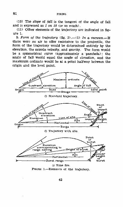
81 FIRING
(10) The slope of tall is the tangent of the angle of fall and is expressed as 1 on 10 (or so much).
(11) Other elements of the trajectory are indicated in figurel.
b. Form of the trajectory (fig. 2) .-0) In a vacuum.-If there were no air to offer resistance to the projectile, the form of the trajectory would be determined entirely by the elevation, the muzzle velocity, and gravity. The form would be a symmetrical curve (approximately a ·parabola) ; the angle of fall would equal the angle of elevation, and the maximum ordinate would be at a point halfway between the origin and the level point.
Horizont~---L----~~~~-
~-----------------£~nge--------~-~
0 Trajectory with site.
FIGURE trajectory.
42
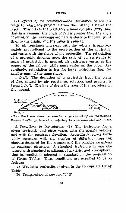
FIRING 81
(2J Effects of air resistance.-<a> Resistance of the air tends to retard the projectile from the instant it leaves the piece. This makes the trajectory a more complex curve than that in a vacuum; the angle of fall is greater than the angle of elevation, the maximum ordinate is closer to the level point than to the origin, and the range is reduced.
(b) Air resistance increases with the velocity, is approximately proportional to the cross-section of the projectile, and varies with the shape of the projectile. The retardation of a projectile depends upon the ratio of air resistance to mass of projectile; in general, air resistance varies as the square of the caliber, while mass varies as the cube." Accordingly, retardation is less for large projectiles than for smaller ones of the same shape.
c. DT"i/t.-The deviation of a projectile from the plane of fire, caused by air resistance, rotation, and gravity, is termed drift. The line of fire is the trace of the trajectory on the ground.
Ori&in
(Note the tremendous decrease In range caused by air resistance.) FIGURE 2.-Comparison of a trajectory in a vacuum and one In air.
d. Variations in traject_ories.-<1) The trajectory for a given projectile and piece varies with the muzzle velocity and with the quadrant elevation. Accordingly, range flexibilitY increases with the number of different propelling charges designed for the weapon and the possible variations in quadrant elevation. A standard trajectory is one obtained with standard conditions of materiel and atmosphere; that is, conditions adopted as. standard in the preparation of Firing Tables. These conditions are assumed to be as follows:
(a) Weight of projectile, as given in the appropriate Firing Table.
(b) Temperature of powder, 70° F.
43
81 FIRING
(C) Air density, that corresponding to 29.53 inches of mercury at 59° F. at the battery, considered as 100 percent.
<d) Air temperature, 59° F. at the battery. (e) No wind. (2) Variations from the standard conditions given in (1)
above have the following effects on projectiles: (a) Weight ot prajectile.-A projectile heavier than stand
ard causes a decrease in the range for the lower elevations, but an increMe in range for the higher elevations. A projectile lighter than standard has the opposite effect.
(b) .Temperature of powder.-A powder temperature higher than standard causes an increase in muzzle velocity and consequently an increase in the range; a powder temperature lower than standard similarly causes' a decrease.
(C) Air density.-Air density above normal (over 100 percent) offers more resistance to the projectile and consequently causes a decrease in the range; air density below normal similarly causes an increase.
(d) Air temperature (elasticity) .-Air temperature higher than normal causes an increase in range; lower than normal, a, decrease.
(e) Wind.-A head wind causes a decrease in the range, a rear wind an increase; a cross wind from the right <Ieft) forces the projectile to the left <right) ; an oblique wind, having components both parallel and perpendicular to the direction of fire, affects both range and deflection.
e. Time fire <fig. 1) .-In firing time-fuzed projectiles which ma.y be burst in the air by appropriate settings, the point of burst is the point at which the burst takes place or would have taken pl~Lce if not obstructed. The following effects obtain in time fire:
(1) Making a corresponding change in range settings of the piece and fuze setter, the corrector and site remaining constant, results in no change in the height of burst.
<2) By changing only the corrector, the burst is drawn back or adva.nc.ed along the trajectory, resulting in a change in height of burst and burst range.
(3) Changing only the site results in a corresponding raising or lowering of the burst practically in a vertical line.
44
FmiNG 81-82
The burst range is not changed but the height of burst and trajectory are changed.
<4> By making a change in the corrector and a compensating change in site, the height of burst remains constant. The trajectory and burst range are changed.
f. Rigidity of the trajectory.-The theory of the rigidity of the trajectory is the assumption that the trajectory may be tilted up or down through small vertical angles about the origin without materially affecting its shape. The flatter the trajectory, the more nearly is the assumption correct. The assumption is utilized primarily in bracket fire to correct for the altitude of the target by applying the angle of site to the range or elevation, thus tilting the trajectory up or down about the origin. When using large elevations with large angles of site, errors may be introduced by this assumption, and, in carefUlly prepared fire, elevation corrections should be determined from the complementary angle-of-site tables given in Firing Tables (par. 139 f (6)). Instead of complementary angle-of-site tables, some Firing Tables have position-effect tables which combine the site and the complementary angle of site into one range effect.
g. Firing tables.-Information necessary for the practical handling of trajectories is given in the appropriate Firing Tables.
• 82. INTERIOR BALLISTics.-Accuracy in firing is affected by the following conditions:
a. Wear of the piece <erosion), if uniform, reduces muzzle velocity; if uneven or excessive, it causes variation in muzzle velocity and inaccuracy in the flight of the projectile. When the lands are worn, the projectile is given insufficient spin, and erratic resUlts ensue.
b'. Coppering (deposit of copper from the rotating bands on the surface of the bore) causes inaccuracies, high pressures, and increased erosion.
c. Lack of cleanliness, both with respect to the bore and the projectile, may cause increased erosion and improper centering of the projectile.
177568'--39--4 45
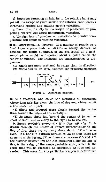
82-83 FIRING
d. Improper ramming or injuries to the rotating band may permit the escape of gases around the rotating band, greatly increasing erosion and causing erratic velocities.
e. Lack of uniformity in the weight of projectiles or propelling charges will cause nonuniform velocities.
f. Varying lots of powders or variations in powder temperature will result in varying velocities.
• 83. DzsPERSION.-a. General.-If a number of rounds were fired from a piece under conditions as nearly identical as possible, the points of impact of the projectiles on a horizontal plane would be dispersed about a point called the center of impact. The following are characteristics of dispersion:
(1) Shots are more scattered in range than in direction. (2) Shots fall in an area, assumed for practical purposes
FIGURE 3.-Dispersion diagram.
to be a rectangle and called the rectangle of dispersion, whose long axis lies along the line of fire and whose center is the center of impact.
(3) Shots are grouped more closely toward the center than toward the edges of the rectangle.
(4) As many shots fall beyond the center of impact as short thereof, and as many to the right as to the left.
b. Range probable error.-<1> If a line AB (fig. 3) is drawn through the center of impact perpendicular to the line of fire, there are as many shots short of the line as over. If a line CD is drawn parallel to AB so that there are as many shots beyond CD as there are between CD and AB, the distance between CD and AB, measured along the line of fire, is the value of the range probable error, which is the error that will be exceeded as frequently as it is not exceeded. This error for any particular weapon is determined
46
FIRING 83-84
by actual firing· and is taken as the index of the accuracy of the piece.
(2) If lines are drawn parallel to AB at intervals of one probable error, the percentages of shots falling in each subdivision will be approximately as indicated in figure 3.
(3) Since the range probable error is known, being given in Firing Tables, the relative position, in range, of the center of impact and a target lying in the rectangle of dispersion may be deduced from the percentage of shots over or short of the target; that is, X (fig. 3) represents the position of the target if 25 percent of the shots are over and 75 percent short; Y, if 10 percent are over and 90 percent short; Z, if 37 percent are over and 63 percent short.
c. Direction probable error.-Dispersion in direction follows the same laws as dispersion in range but is much less. Values are given in Firing Tables.
d. Vertical probable error.-Dispersion in a vertical plane follows the same laws as dispersion in a horizontal pla:ne. The vertical probable error is the product of the range probable error and the tangent of the angle of fall. Values are given in Firing Tables.
e. Dispersion on sloves.-A positive slope is one which rises away from the piece. A negative slope is one which descends a.way from the piece. Dispersion on a positive slope is less, on a negative slope more, than that on a horizontal plane.
f. Height-of-burst probable error.-In time fire, dispersion is due to variations in trajectories and in the time of burning of the fuzes. Distribution follows the law of errors. The rectangle of dispersion for height of burst is derived from the vertical projection of the points of burst; for burst range it is the horizontal projection.
g. Practical a~pplication.-The solution of problems, such as the expenditure of ammunition to obtain a given number of hits in a certain area and the distribution of shots in an area, can be obtained by applying the necessary dispersion scales to the area.
• 84. FoRK.-The fork is a unit of range change used in conduct of fire. It is the change in elevation necessary to
47
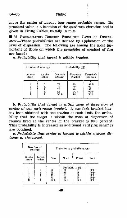
84-85 FmiNG
move the center of impact four range probable errors. Its practical value is a function of the quadrant elevation and is given in Firing Tables, usually in mils .
• 85. PROBABILITIES DEDUCED F'ROM THE LAWS OF DISPER
SION.-These probabilities are derived by application of the laws of dispersion. The following are among the most important of those on which the principles of conduct of fire are based:
a. Probability that target is within bracket.
Number of sensings Probability (%)
At one At the One-fork Two-fork Four-fork limit other bracket bracket bracket
1 1 70 85 92.3 1 2 75 89 96 1 3 76 90 97 2 2 85 94.5 99+ 3 3 92.5 98 99+
b. Probability that target is within zone of dispersion of center of one-forl'G range bracket.-A one-fork bracket having been obtained with one sensing at each limit, the probability that the target is within the zone of dispersion of rounds fired at the center of the bracket is 96.8 percent. This probability i:s increased as additional verifying sensings are obtained.
c. Probability that center of impact is within a given distance of the target.
Number of Distance in probable errors sen sings
In one I In the _::_~;her
One Two Three Four
Probability (%) 1 1 54 86 98 99+ 1 2 51 86 9s. 99+ 1 3 44 80 96 99+ 2 2 70 96 99 99+ 3 3 99+ 99+ 99+ 99+
48
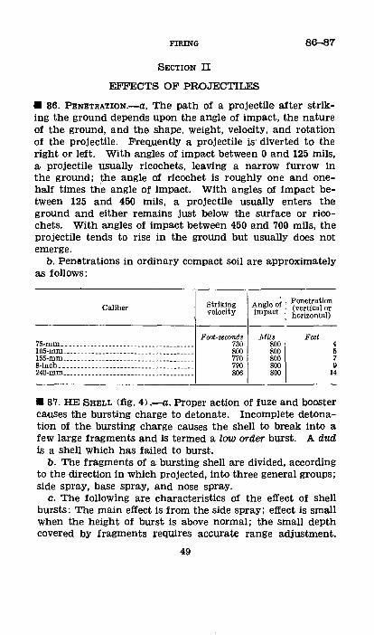
FmiNG 86-87
SECTION II
EFFECTS OF PROJECTILES
• 86. PENETRATION.-a. The path of a projectile after striking the ground depends upon the angle of impact, the nature of the ground, and the shape, weight, velocitY, and rotation of the projectile. Frequently a projectile is· diverted to the right or left. With angles of impact between 0 and 125 mils, a projectile usually ricochets, leaving a narrow furrow in the ground; the angle of ricochet is roughly one and onehalf times th-e angle of impact. With angles of impact between 125 and 450 mils, a projectile usually enters the ground and either remains just below the surface or ricochets. With angles of impact between 450 and 700 mils, the projectile tends to rise in the ground but usually does not emerge.
b. Penetrations in ordinary compact soil are approximately as follows:
Caliber
75-mm .. _ ------- __ ----------- ___ -----------105-mm ____________________________________ _ 155-mm ... _________________________________ _ 8-inch. _ ---------------- __________________ __ 240-mm ____________________________________ _
Striking velocity
Foot-seconds 730 800 770 790 806
Angle of impact
Mils 800 800 800 800 800
Penetration (vertical or horizontal)
Feet 4 5 7 9
14
• 87. HE SHELL (fig. 4> .-a. Proper action of fuze and booster causes the bursting charge to detonate. Incomplete detonation of the bursting charge causes the shell to break into a few large fragments and is termed a law order burst. A dud is a shell which has failed to burst.
b. The fragments of a bursting shell are divided, according to the direction in which projected, into three general groups; side spray, base spray, and nose spray.
c. The following are characteristics of the effect of shell bursts: The main effect is from the side spray; effect is small when the height of burst is above normal; the small depth covered by fragments ;requires accurate range adjustment.
49
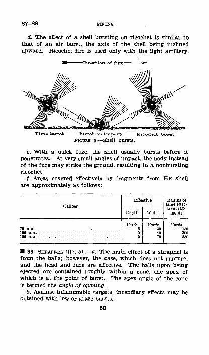
87-88 FIRING
d. The effect of a shell bursting on ricochet is similar to that of an air burst, the axis of the shell being inclined upward. Ricochet fire is used only with the light artillery.
I3 Direction or fire----
Time buret ~urat. on irnpa.ct. Ricochet, bul"st.
FIGURE 4.-Shell bursts.
e. With a qUick fuze, the. shell usually bursts before it penetrates. At very small angles of impact, the body instead of the fuze may strike the ground, resulting in a nonbursting ricochet.
f. Areas covered effectively by fragments from HE shell are approximately as follows:
Caliber
75-mm ••••.. --------------------------------------105-mm. _________________________________________ _ 155-mm __________________________________________ _
Effective Radius of -·---,----I large effec
tive trag-Depth Width ments
Yards 5 9 9
Yards 30 40 70
Yards 150 300 550
• 88. SHRAPNEL (fig. 5) .--a. The main effect of a shrapnel is from the balls; however, the case, which does not rupture, and the head and fuze are effective. The balls upon being ejected are contained roughly within a cone, the apex of which is at the point of burst. The apex angle of the cone is termed the angle of opening.
b. Against inflammable targets, incendiary effects may be obtained with low or graze bursts.
50
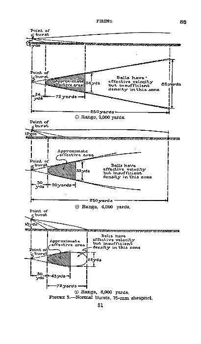
FIRING
Point. oC
~--------------------250Jr&rds-------------------~ CD.Range, 2,000 yards.
Point. of
~-------------------250y&rd~------------------~
0 Range, 4,000 yards.
y~o
Be.lla have eCCeetive veloeit.y but. ine.uffieienl:. den&it.y in t.hi& z.one
0 Range, 6,000 yards. FIGURE 5.--Normal bursts, 75-mm shrapnel.
51
88

89 FIRING
• 89. CHEMICAL SHELL.-a. Fuzes.-Since it is ~sually desired to distribute the filler of the shell in air rather than in a crater, a quick fuze should be used if the shell will not ricochet. If the angle of impact will give a large proportion of ricochets, a delay fuze should be used.
b. Smoke.-The type of smoke shell in use is WP, containing white phosphorus. In addition to its smoke-producing effect, WP has a marked incendiary effect and inflicts severe burns on personnel.
52
CHAPTER 3
PREPARATION OF FIRE
90-93
Paragraphs
SECTION I. GeneraL------------------------------ 90-94 II. Preparation of fire with instruments___ 95-109
III. Firing charts __________________________ 110-114
IV. Survey operations, plans, and proce-dure ________________________________ 115-122
V. Preparation of fire from firing charts __ 123-133 VI. Schedule fires _________________________ 134-142
SECTION I
GENERAL
B 90. DEFINITJON.-Preparation ot fire is the determination of firing data. The object of preparation is to obtain the most accurate data possible under existing conditions.
• 91. UNITs oF MEAsURE.--The unit of length or distance is the yard. The unit of angular measure is the mil <nr> equal to 1/6,400 part of the circumference of a circle. Practically a mil is the angle subtended by one yard at a distance of 1,000 yards. The mil relation is expressed by W=Rxm where m is the angular width of the object in mils, W is the width of the object in yards, and R is the range or distance in thousands of yards. The mil relation is approximately true for angles of less than 400 mils .
• 92. DATA NECESSARY TO OPEN FIRE.-The following information is necessary to have the battery deliver the desired fire:
a. Direction. b. Distribution. c. Projectile, fuze, and, when necessary, charge. d. Pieces to fire and method of fire. e. Site and range, or quadrant elevation .
• 93. STEPS IN PREPARATION.-There are three general steps in preparation of fire as follows:
a. Determining basic data which are direction, distribution, site, and range.
53
93-96 FIRING
b. Determining corrections for conditions not standard. c. Converting basic or corrected data to l)ettings for the
piece .
• 94. KINDS OF PREPARATION.-Preparation Of fire iS made with instruments or from firing charts, depending upon the time and facilities available for getting basic data and corrections. In either case the preparation is as accurate as circumstances permit.
SECTION II
PREPARATION OF FIRE WITH INSTRUMENTS
Ill 95. GENERAL.-Instruments ordiharily are used for the preparation of data when time is pressing or when other facilities are lacking. Means available are the battery commander's telescope, aiming circle, prismatic compass, range finder, field glasses, and calibrated hand or other object. Fires with data prepared with instruments must be observed and data corrected as a result of observation.
• 96. DIRECTION.-Direction is obtained by determining the firing angle, the Y-azimuth of the direction of fire, or the shift from a known direction. Direction is usually determined from an observation post and converted for use at the battery, Occasionally, direction may be determined by actual measurement at the battery.
a. Terms used.-(1) The firing angle is the clockwise horizontal angle from the target to the aiming point, vertex at the piece. The piece as here used means the base piece <usually No. 1).
(2) The measured angle is the clockwise horizontal angle, vertex at the observation post, between the target and the aiming point, base point, or other datum point. The one exception to this is in the computation of a shift (par. 100), in which case the measured angle is the smaller (not necessarily clockwise) angle between the base point and target as measured at the observation post.
(3) The target offset is the horizontal angle between the piece and observation post, vertex at the target.
54
FIRING 96-97
(4) The aiming-point offset is the horizontal angle between the piece and observation post, vertex at the aiming point.
b. Deflection.-The firing angle, corrected, is converted to a setting, termed the deflection. to be applied to the sights. An increase of deflection moves the plane of fire to the left; a decrease moves it to the right.
(1) Panoramic signt.-If graduated from 0 to 3,200, the deflection is the firing angle when the latter is less than 3,200; if greater, it is the firing angle less 3,200. If graduated from 0 to 6,400, the deflection is the firing angle.
(2) French sight.-To convert a firing angle to deflection, add the deflection constant, 100, to the firing angle; subtract the larges't multiple of 1,600; the largest even number of hundreds in the result is the plateau setting; the remainder, after subtracting this even number of hundred mils, is the drum setting.
c. Abbreviations and symbols. M, measured angle. A, firing angle. T, target or target offset. P, aiming point or aiming-point offset. G, piece. 0, observation post.
OP, distance, in thousands of yards, from 0 toP. OG, distance, in yards, from 0 to G.
r, distance, in thousands of yards, from 0 to T. R, distance, in thousands of yards, from G to T .
• 97. DETERMINING DIRECTION AT THE OBSERVATION POST.
a. General.-The principle of each method of determining direction is to viSualize an angle at 0 whose sides are parallel to the sides of the direction angle used to lay the piece and thus equal to it. For example, in figure 6, OT' is parallel to GT and OP' is parallel to GP. It is evident that the target offset T equals the angle TOT' and the aiming-point offset P equals the angle POP'. These offsets applied to the angle TOP (the measured angle M) give the angle T'OP', which is equal to the angle TGP (the firing angle A>, since their sides are parallel.
55
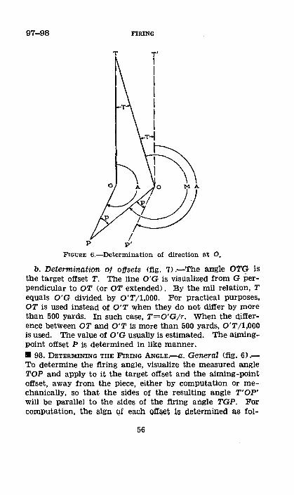
97-98 FIRING
T
I p p'
FIGURE 6.-Determinatlon of direction at 0.
b. Determination of offsets (fig. 7> .-The angle OTG is the target offset T. The line O'G is visualized from G Perpendicular to OT (or OT extended). By the mil relation, T equals O'G divided by O'T/1,000. For practical purposes, OT is used instead of O'T when they do not differ by more than 500 yards. In such case, T=O'Gjr. When the difference between OT and O'T is more than 500 yards, O'T ;1,000 is used. The value of O'G usually is estimated. The aimingpoint offset P is determined in like manner . • 98. DETERMINING THE FIRING ANGLE.--a. General (fig. 6) .To determine the firing angle, visualize the measured angle TOP and apply to it the target offset and the aiming-point offset, away from the piece, either by computation or mechanically, so that the sides of the resulting angle T'OP' will be parallel to the sides of the firing angle TGP. For computation, the sign Qf each ofi::;et is determined as fol-
56
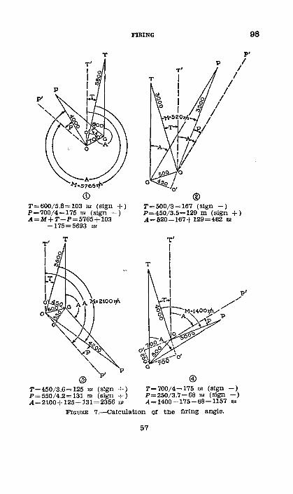
T
T=600/5.8=103 m (sign+> P=700/4=175 m (sign -) A=M+T-P=5765+103
-175=5693 m
T=450/3.6=125 m (sign+> P=550/4.2=131 m (sign+) A=2100+l25+131=2356 m
FIRING 98
T
P' P I
I I
I I
I I
I
/
® T=500/3=167 (sign-) P=450/3.5=129 m (sign +) A=520-167+129=482 m
@) T=700/4=175 m (sign -) P=250/3.7=68 m (sign -) A=1400-175-68=1157 m
FIGURE 7.-Calculat!on Of the firing angle.
57
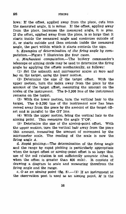
98 FIRING
lows: If the offset, applied away from the piece, cuts into the measured angle, it is minus. If the offset, applied away from the piece, increases the measured angle, it is plus. If the offset, applied away from the piece, is so large that it starts inside the measured angle and continues outside of it, or starts outside and then extends inside the measured angle, the part Within which it starts controls the sign.
b. Examples of determination of the firing angle by computation.-Figure 7 illustrates the four cases.
c. Mechanical computation.-The battery commander's telescope or aiming circle may be used to determine, the firing angle by applying the offsets mechanically, as follows:
(1) Set the azimuth and micrometer scales at zero and lay on the target, using the lower motion.
(2) Determine the size of the target offset. With the upper motion, turn the index away from the piece by the amount of the target offset, measuring the amount on the scales of the instrument. The 0-3,200 line of the instrument remains on the target.
(3) With the lower motion, turn the vertical hair to the target. The 0-3,200 line of the instrument now has been moved away from the piece by the amount of the target offset and is parallel to the GT line.
(4) With the upper motion, bring the vertical hair to the aiming point. This measures the angle T'OP.
(5) Determine the size of the aiming-point offset. With the upper motion, turn the vertical hair away from the piece this amount, measuring the amount of movement by the micrometer scale. The reading of the scale is now the firing angle A.
d. Rapid plotting.-The determination of the firing angle and the range by rapid plotting is particularly appropriate when the target offset or aiming-point offset is so large that use of the mil relation is not sufficiently accurate <that is, when the offset is greater than 400 mils). It consists of drawing a diagram to scale and measuring therefrom the firing angle andl the range.
e. 0 as an aiming point (fig. 8) .-U) If an instrument at the observation post is used as an aiming point, M is the
58
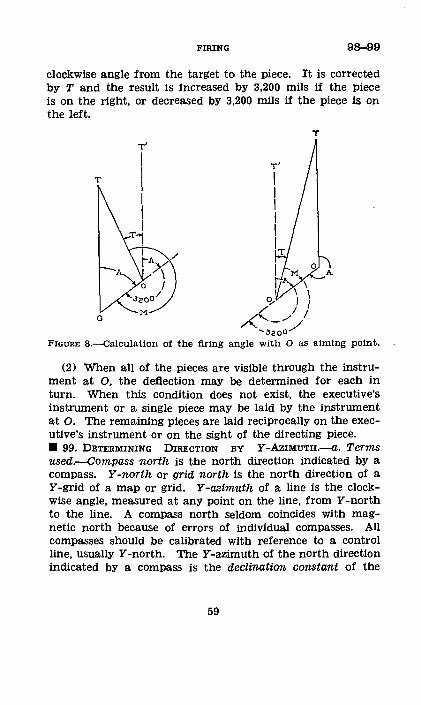
FIRING 98-99
clockwise angle from the target to; the piece. It is corrected by T and the result is increased by 3,200 mils if the piece is on the right, or decreased bY 3,200 mils if the piece is on the left.
T
M A \
\ I g... I I
o (( j I / - /
...... 3200 .......
T
FIGURE a.--calculation of the firing angle with 0 as aiming point.
(2) When all of the pieces are visible through the instrument at 0, the deflection may be determined for each in turn. When this condition does not exist, the executive's instrument or a single piece may be laid by the instrument at 0. The remaining pieces are laid reciprocally on the executive's instrument or on the sight of the directing piece . • 99. DETERMINING DIRECTION BY Y -AZIMUTH.--a. Terms used.-Compass north is the north direction indicated by a compass. Y -north or grid north is the north direction of a Y -grid of a map or grid. Y -azimuth of a line is the clockwise angle, measured at any point on the line, from Y -north to the line. A compass north seldom coincides with magnetic north because of errors of individual compasses. All compasses should be calibrated with reference to a control line, usually Y-north. TheY-azimuth of the north direction indicated bY a compass is the declination constant of the
59
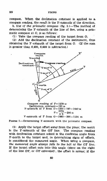
99 FIRING
compass. When the declination constant is applied to a compass reading, the result is the Y -azimuth of the direction.
b. Use of the prismatic compass (fig. 9J-ll'he method of determining the Y -azimuth of the line of fire, using a prismatic compass at 0, is as follows:
(1) Take the compass reading of the target from 0. (2) Add the declination constant of the instrument, thus
obtaining the Y -azimuth of the target from 0. (If the sum is greater than 6,400, 6,400 is subtracted.)
c. Campa&~ reading of T= 1250 m
Declination constant= 190 m ¥-azimuth ofT from 0=1250+190=1440m
T= 1000
==286m 3.5
¥-azimuth of T from G=1440-286=1154 m
FIGURE 9.-Determining ¥-azimuth with the prismatic compass.
(3) Apply the target offset away from the piece; the result is the Y -azimuth of the GT line. The compass reading with declination constant added is the clockwise angle from Y -north to the target and, in determining signs of offsets, is considered the measured angle. When using a compass, the measured angle always falls to the left of the OT line. If the target offset cuts into this angle (piece on the right of the line OT, or OT extended), the offset is minus; if the
60
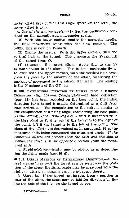
FIRING 99-101
target offset falls outside this angle (piece on the left), the target offset is plus.
c. Use of the aiming circle.-( 1) Set the declination constant on the azimuth and micrometer scales.
(2) With the lower motion, center the magnetic needle, the final movement b€ing with the slow motion. The 0-3200 line is now on Y -north.
(3) Clamp the needle. With the upper motion, turn the vertical hair to the target. This measures the Y -azimuth . of the target from 0.
( 4) Determine the target offset. Apply this to the Yazimuth found in (3) above. This is done mechanically as follows: with the upper motion, turn the vertical hair away from the piece by the amount of the offset, measuring the amount of movement by the micrometer scale. The reading is the Y -azimuth of the GT line .
• 100. DETERMINING DIRECTION BY SHIFTS FROM A KNOWN DIRECTION (fig. 10) .-a. Computation.-If base deflection (par. 52) has been recorded on the base point, the initial direction for a target is usually determined as a shift from base deflection. The computation of the shift is similar to the computation of a firing angle, considering the base point as the aiming point. The angle of a shift is measured from the base point to T; it is right if the target is to the right of the point, left if the target is to the left of the point. The signs· of the offsets are determined as in paragraph 98 a, the measured shift being considered the measured angle. If the combined offsets are greater than tlw shift and the sign is minus, the shift is in the opposite direction from the measured shift.
b. Rapid oplotting.-8hifts may be plotted as in determining the firing angle (par. 98 d) .
• 101. DIRECT METHODS OF DETERMINING DIRECTION.-a. Direct measurement.-If the target can be seen from the position of the piece, the firing angle may b€ measured with the sight or with an instrument set up adjacent thereto.
b. Lining in.-If the target can b€ seen from a position in rear of the piece, the piece may b€ laid for direction by lining the axis of the tub€ on the target by eye.
177568°-39--5 61

101-102 FmiNG
c. Lewing on an airplane.-Direction for a target may be given by laying a piece or an instrument at the battery position on an airplane which signals when it is on the GT line. The airplane may signal when it is on the GT line extended to the rear of the battery. The piece may be laid by setting the deflection scale so that the line of sighting is parallel to the axis of the bore, and traversing the piece to place the vertical hair on the airplane; otherwise, the piece is laid in a known direction and the shift to the airplane is measured by the sight. When an instrument is used, the same procedure is followed, the piece being laid reciprocally on the instrument.
G 0
FIGURE 10.-8hlfts.
d. Air burst.--A round is fired in the general direction of the target at a range which will not endanger friendly troops and at a site and correcter to give a visible air burst. When the burst is seen, its deviation from the target is measured at the observation post and the direction of the piece is corrected accordingly .
• 102. DISTRIBUTION.--a. Terms used.-(1) A sheaf consists of the planes of fire of two or more pieces of a battery, considered as a group.
62
FIRING 102
(2) A parallel sheaf is one in which the planes of fire are parallel.
(3) An open sheaf is one effectively covering a maximum of front without sweeping.
(4) A converged sheaf is one in which the planes of fire are converged at the points of burst.
(5) A crossed sheaf is one in which the planes of fire converge at a point short of the points of burst, the bursts appearing in reverse positions from the pieces firing.
(6) Dettection difference <DD> is a uniform change in the deflection of adjacent pieces to obtain a desired width of sheaf.
b. Parallel sheaf.-The executive usually is charged with the formation of a parallel sheaf. Upon occupation of position, he lays the battery parallel in the direction indicated by the battery commander or, in the absence of specific instructions, in the general direction of fire. When the initial direction is given by compass or by base angle (par. 124), the pieces are laid by the aiming circle or other instrument and a parallel sheaf is formed directly; when given by use of an aiming point, the executive may form a parallel sheaf as explained above or by determining a deflection difference. When the battery commander desires a parallel sheaf formed by firing, he commands: ON NO. 1 ADJUST SHEAF PARALLEL (par. 75) followed by the range at which it is desired to adjust the sheaf. When the battery commander desires a parallel sheaf formed without firing, he commands: ON NO. 1 FORM SHEAF PARALLEL (par. 60).
c. Converged sheaf.-The battery commander usually converges the sheaf prior to opening it to flt the target or adjusting point. This is accomplished by the command: CONVERGE AT (SUCH RANGE>; the range announced is the multiple of 500 nearest the initial range. When the initial direction is given by means which do not give a parallel sheaf directly (aiming point and deflection), the executive must first form the sheaf parallel before converging it. The sheaf is converged by the executive on No. 1 (par. 62) 0
d. Fire without sweeping.-(!) The interval between the bursts of adjacent pieces is one third the desired width of
63
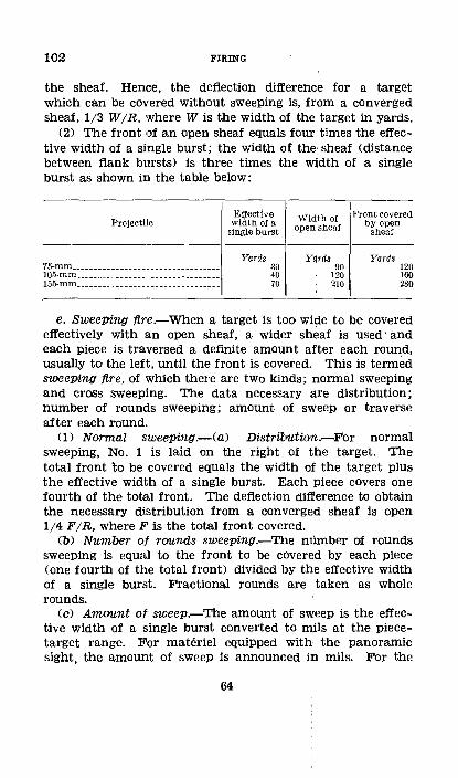
102 FIRING
the sheaf. Hence, the deflection difference for a target which can be covered without sweeping is, from a converged sheaf, 1/3 W/R, where W is the width of the target in yards.
(2) The front of an open sheaf equals four times the effective width of a single burst; the width of the sheaf (distance between flank bursts) is three times the width of a single burst as shown in the table below:
Projectile
75-mm _________________________________ _ 105-mm ________________________________ _ 155-mm ________________________________ _
Effective width of a
single burst
Yards 30 40 70
Width of open sheaf
Yards 90
120 210
Fran t covered by open
sheaf
Yards 120 160 280
e. SweePing fire.-When a target is too wi~e to be covered effectively with an open sheaf, a wider sheaf is used· and each piece is traversed a definite amount after each round, usually to the left, until the front is covered. This is termed sweePing fire, of which there are two kinds; normal sweeping and cross sweeping. The data necessary are distribution; number of rounds sweeping; amount of sweep or traverse after each round.
(1) Normal sweePing.-(a) Distril:outian.-For normal sweeping, No. 1 is laid on the right of the target. The total front "to be covered equals the width of the target plus the effective width of a single burst. E!ach piece covers one fourth of the total front. The deflection difference to obtain the necessary distribution from a converged sheaf is open 1/4 F/R, where F is the total front covered.
(b) Number of rounds sweeping.-The nUm.ber of rounds sweeping is equal to the front to be covered by each piece (one fourth of the total front) divided by the effective width of a single burst. Fractional rounds are taken as whole rounds.
(c) Amount of sweep.-The amount of sweep is the effective width of a single burst converted to mils at the piecetarget range. l~or materiel equipped with the panoramic sight, the amount of sweep is announced in mils. For the
64
FIRING 102
75-mm gun, M1897, with French sight, the amount of sweep is announced in turns of the handwheel to the nearest whole number, each turn traversing the piece 1.8 mils.
(d) Rapid computation of distribution jor standard areas.-Usually the width of the target or target area is assigned as a multiple of 100 yards (par. 137). In order quickly to determine the deflection difference from a converged sheaf and, in the case of sweeping fire, the number of rounds sweeping and the amount of sweep, the following procedure is used:
75-mm and 105-mm materiel
Deflection difference: Open 30/ R from a converged sheaf for each 100 yards of target width.
Number of rounds: Number of rounds equals number of 100 yards of target width.
Amount of sweep: 30/R mils. For the 75-mm gun with French sight, the number of turns is 17/R.
155-mm materiel
Deflection difference: Same as for 75-mm or 105-mm materiel.
Number of rounds: Battery one round for 100- and 200-yard widths; two rounds sweeping for 300- and 400-yard widths.
Amount of sweep: 60/R mils. (2) Cross sweeping.-(a) In cross sweeping, the line of
fire of No. 1 is placed on the right of the target; those of Nos. 2 and 3 on the middle; and that of No. 4 on the left. Nos. 1 and 3 sweep to the left; Nos. 2 and 4 sweep to the right. Each piece covers half the entire width of the area. In this manner each. platoon covers half the target width with the superimposed fire of two pieces.
(b) Cross sweeping is used in prolonged fire when it is desired to rest the pieces in turn, leaving the front covered by fire. It is not used for wide fronts because of the wide traverse required of each piece and the possibility of large gaps in the front covered by fire; it is not used when five or more
65
102-104 FIRING
rounds sweeping are necessary to cover the target. Cross sweeping usually is used only for the rolling barrage.
f. Shifting fire.-When the width of the target is too great to be covered With an open sheaf and sweeping fire is not to be used, the target should be attacked by a succession of open sheafs.
• 103. SITE.--a. comwtation.-From 0 measure the site (plus or minus) of the target and of the piece and calculate the difference in altitude, in yards, between target and piece. Convert this difference into mils of si.te. The site is plus if the target is above the piece, minus if below.
b. Setting.-(!) French 75-mm gun.-The site is announced as plus or minus, zero being horizontal. The least setting is 5 mils.
(2) Other materiel.-On all other materiel, the horizontal site setting is marked 300. A site below horizontal is subtracted from 300, one above is added. The least setting is one mil .
• 104. PROJECTILE, CHARGE, AND FuzE.-The type of projectile, the charge, and the fuze are determined by the effect desired.
a. Projectile.-For destruction and for fire against personnel with cover, high-explosive shell is used. For fire against personnel in the open, shrapnel or high-explosive shell is used. Shrapnel is less effective at long ranges; for the 75-mm gun, high-explosive shell is preferable to shrapnel at ranges greater than 4,000 yards.
b. Charge.-<1) Howitzer.-The charge is determined largely by the angle of impact desired. The charge selected should be such that the target range is not more than three-fourths the maximum range for the charge. If several charges are suitable, the smaller charge produces less wear and gtves a greater angle of impact and greater fragmentation effect; the larger charge usually gives the smaller dispersion. In precision fire for destruction, the charge giving the greatest accuracy <least dispersion) usually is used.
(2) Gun.-The lowest charge consistent with the mission is used; this may often be reduced charge. In guns having
66
FIRING 104-107
supercharge, it is used only when necessary to obtain greater range or accuracy.
c. Fuze.-<1) Impact.-For action against personnel, the quick fuze usually is used. When firing at ranges at which ricochets occur, the delay ·fuze should be used (par. 87). In fire for destruction, the quick fuze is used where fragment or blast effect is desired; the delay fuze when penetration is necessary.
(2) Time.-A corrector setting giving an equal number of airs and grazes is desired for adjustment. The height of burst depends upon site as well as corrector setting, and both must be determined accurately in order to be effective. The corrector for the first firing must be estimated. Cold weather requires a corrector higher than standard; warm weather, a corrector lower than standard. When a corrector giving the proper height of burst for adjustment has been determined, it should be used to start later adjustments.
• 105. PIECES TO FIRE.-Precision fire habitually and bracket fire occasionally are started with one piece. However, in bracket fire when the data are accurate, when the target is fleeting, or when observation is difficult, it is advantageous to start fire with the battery.
• 106. METHOD OF FIRE.--a. If fire is opened with a single piece, the method of fire usually is one round. When the battery or platoon is fired during adjustment, the method of fire usually is by salvo. When the target is moving rapidly, or is capable of extremely rapid movement, it may be desirable to adjust with battery (or platoon) volleys.
b. In fire for effect, the method of fire usually is by volley or volley fire sweeping. In some cases, continuous fire may be employed.
• 107. RANGE.--a. Determination.-Range is determined by the most accurate means available. When the range is determined from the observation post, any difference between r and R must be considered.
b. Range settings.-Range scales are designed to give the elevation for a definite projectile and charge; hence, settings
67
107-110 FIRING
for other combinations of projectiles and charges must be determined from the Firing Tables.
c. Elevation settings.-When the gunner's quadrant or elevation scale is used, the elevation corresponding to the range is obtained from the Firing Tables and to this is applied the site.
II 108. UNITS OF ANNOUNCEMENT.-If data ave prepared very accurately, the settings so computed may be used. Usually, it is suffi.ciently accurate to announce initial data in the following units: defiection or compass, to the nearest 10 mils; convergence, to the nearest 500 yards; defiection difference, to the nearest mil; site, to the nearest 5 mils; corrector, to the nearest five points; range, to the nearest 100 yards; and elevation, to the nearest 10 mils .
• 109. MINIMUM ELEVATION.-TO determine the minimum elevation before a position is occupied by the pieces, the procedure is as follows:
a. Measure the site of the mask from the position to be occupied, using an aiming circle or other instrument.
b. Add thereto the elevation for the piece-mask range for the available ammunition having the lowest muzzle velocity.
c. Add two forks at the piece-mask range. d. If the mask is occupied by friendly troops, add the num
ber of mils subtended by 5 yards at the piece-mask range.
SECTION ill
FIRING CHARTS
• 110. DESCRIPTION.-a. A firing chart: is a diagram, accurately constructed to a known scale, showing the relative positions of batteries, base points, base lines, check points, targets, and other data pertaining to the preparation of fire (par. 124). It usually is constructed on a grid sheet but may be on a map, if available, or map substitute (air photo).
b. Subject to restrictions imposed by higher authority, the battalion commander prescribes the firing chart to be used by his battalion. The firing chart used by the batteries for
68
FIRING 110-111
the preparation of firing data must be a duplicate of the one on which fire missions are assigned by the battalion.
c. This section discusses the characteristics of the several types of firing charts. The operations by which a firing chart is built up are considered in section IV. The battalion observed-fire chart is described in chapter 5 .
• 111. MAPS AND GRIDS (AR 100-15 and TM 2180-5) .-If an accurate map or map substitute of suitable scale is available, it is used for the firing chart. If suitable maps are lacking, as will usually be the case, composites, mosaics, or provisional fire-control data sheets may be used to build up firing charts. Single vertical air photographs may be used alone or in conjunction with maps or charts.
a. Grid systems.-When a map with a standard grid is not available, a grid system may be improvised. A point is arbitrarily assigned coordinates and a definite direction is arbitrarily assigned a Y -azimuth. The grid system of each subordinate unit must conform to this system.
b. Coordinates.-The distance of any point east of the zero Y -line is the X coordinate and the distance north of the zero X-line is the Y coordinate. In writing coordinates, the X coordinate is written first and the whole inclosed in parentheses. Thus, to the nearest yard (204.72"9-186.684); to the nearest 10 yards (204.73-186.68) ; to the nearest 100 yards (204.7-186.7). It is seldom necessary to give more than two digits to the left of the decimal for each coordinate; for example, (04. 729--86.684) . If the point is fixed within an area 10,000 yards square, only one digit. need be given before the decimal. Thus the above coordinates would be (4.729-6.684); to the nearest 100 yards, (4.7-6.7). If a large number of points are being designa,ted by abbreviated coordinates, the decimals and dash may be omitted, thus (4767).
c. Measurements.-(!) Angles.-Measurements of angles on a map or chart are made with a protractor.
(2) Y -azimuth.-The Y -azimuth of a line may be measured at any point where this line crosses a Y -line or X-line.
(3) Distances.-Distances are measured by accurate scales, graduated in yards.
69
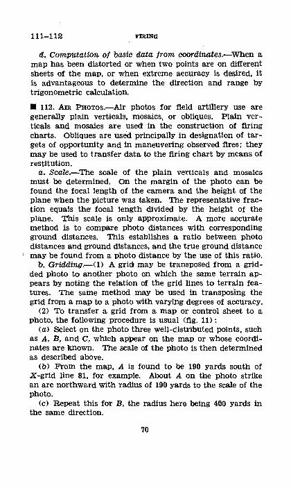
111-112 FIRING
d. Computation of basic data from coordinates.-When a map has been distorted or when two points are on different sheets of the map, or when extreme accuracy is desired, it is advantageous to determine the direction and range by trigonometric calculation.
• 112. Am PHoTos.-Air photos for field artillery use are generally plain verticals, mosaics, or obliques. Plain verticals and mosaics are used in the construction of firing charts. Obliques are used principally in designation of targets of opportunity and in maneuvering observed fires; they may be used to transfer data to the firing chart by means of restitution.
a. Scale.-The scale of the plain verticals and mosaics must be determined. On the margin of the photo can be found the focal length of the camera and the height of the plane when the picture was taken. The representative fraction equals the focal length divided by the height of the plane. This scale is only approximate. A more accurate method is to compare photo distances with corresponding ground distances. This establishes a ratio between photo distances and ground distances, and the true ground distance may be found from a photo distance by the use of this ratio.
b. Gridding.-U> A gricb may be transposed from a gridded photo to another photo on which the same terrain appears by noting the relation of the grid lines to terrain features. The same method mey be used in transposing the grid from a map to a photo with varying degrees of accuracy.
(2) To transfer a grid from a map or control sheet to a photo, the following procedure is usual (fig. 11> :
<a> Select on the photo three well-distributed points, such as A, B, and C, which appear on the map or whose coordinates are known. The scale of the photo is then determined as described above.
<b> From the map, A is found to be 190 yards south of X-grid line 81, for example. About A on the photo strike an arc northward with radius of 190 yards to the scale of the photo.
<c> Repeat this for B, the radius here being 400 yards in the same direction.
70
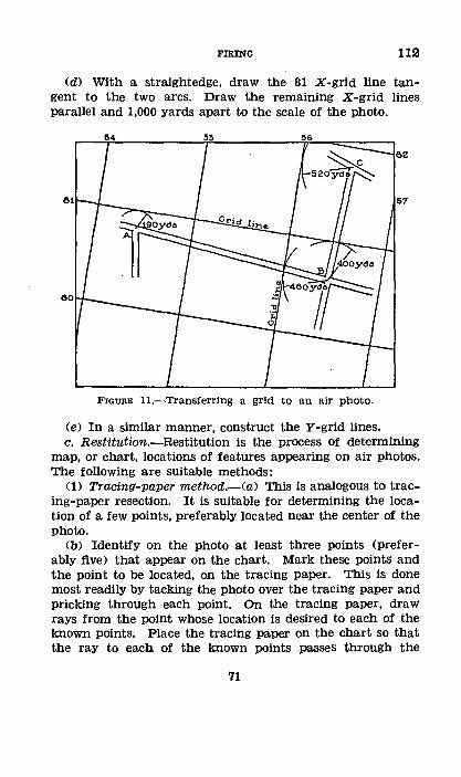
FIRING 112
(d) With a straightedge, draw the 81 X-grid line tangent to the two arcs. Draw the remaining X-grid lines parallel and 1,000 yards apart to the scale of the photo.
FIGURE H.-Transferring a grid to an air photo.
<e> In a similar manner, construct the Y-grid lines. c. Rootitution.-Restitution is the process Of determining
map, or chart, locations of features appearing on air photos. The following are sUitable methods:
<1> Tracing-paper method.-<a> This is analogous to tracing-paper resection. It is sUitable for determining the location of a few points, preferably located near the center of the photo.
<b> Identify on the photo at least three points (preferably five> that appear on the chart. Mark these points and the point to be located, on the tracing paper. This is done most readily by tacking the photo over the tracing paper and pricking through each point. On the tracing paper, draw rays from the point whose location is desired to each of the known points. Place the tracing paper on the chart so that the ray to each of the known points passes through the
71

112 FIRING
chart location of the corresponding point. The point whose location is desired is then in its true relative position to the known points, and it is located ·on the cQart by pricking through its position on the tracing paper on to the chart.
(2) Grid metlwd.-This method is suitable for transferring a mass of detail. Three or more well-distributed points about the margin of the area to be transferred are selected on the photo and identified on the chart. The points are joined by straight lines on both the photo and the chart to form homologous figures. The opposite sides of these two figures are divided into the same number of equal parts, and, by joining the points of division, the two areas (photo and chart) are subdivided into the same number of small homologous figures. Locations then are transferred by inspection, the detail appearing in each figure of the photo being transferred to the corresponding figure of the chart.
(3) Intersection method (fig. 12) .-(a) Two well-separated points whose chart locations are known are identified on the photo. The line joining them is taken as a base. The location of a point is determined as follows: On the photo, draw lines from the point to the ends of the base; on the chart, using the corresponding base, draw back rays making the same base angles as on the photo; the intersection of these rays is the chart location of the point.
(b) When several points are to be transferred, the same procedure can be followed graphically. Stack together the photo and two sheets of tracing paper, with the photo on top; fasten these down securely with thumbtacks. With a sharp needle, prick through the two ends of the selected base line (ab, fig. 12) and each of the several targets, such as T,, T,, and T,. Remove the photo; on the upper tracing paper draw the rays, ab, aT,, aT., aT.. On the lower tracing paper draw the rays ba, bT,, bT,, bT,. Place both sheets of tracing paper on the firing chart so that point a on the upper sheet is over a on the chart, and b on the lower sheet is over b on the chart. Orient the upper sheet by means of the ray ab, and the lower sheet by' means of ba. Prick through the intersections of corresponding rays; for example, the intersection of rays aT, and bT,.. This process locates the targets on the chart.
72
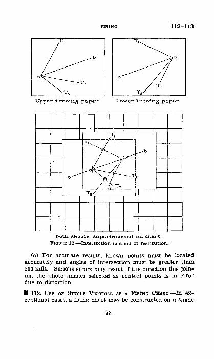
FIRING 112-113
b b
Upper tracini) paper Lower tracing paper
I T,
'1: .. , ------ -----; ,,, I
", I I b
I
i I
/T ~. l
l)ot.h sheet.e .$Uperimpoe.ed on chart
FIGURE 12.-Intersection method of restitution.
(c) For accurate resUlts, known points must be located accurately and angles of intersection must be greater than 500 mils. Serious errors may result if the direction line joining the photo images selected as control points is in error due to distortion .
• 113. USE OF SINGLE VERTICAL AS A FIRING CHART.-ln exceptional cases, a firing chart may be constructed on a single
73
113-116 FmiNG
vertical air photo showing the target area. The problem is one of locating the gun position with respect to the photo. To accomplish this, either two points on the photo or one point on the photo and a direction must be identified and the scale of the photo must be known .
• 114. USE OF MOSAIC AS A FIRING CHART.-The mosaic is used as a firing chart in the same general manner as is a fire-control map. Angular measurements are relatively accurate. The scale of the mosaic must be determined and mosaic distances converted to true ranges by use of the factor, true distance/mosaic measurement, determined as in paragraph 112 a. Altitudes must be determined by comparison with a contoured map or by use of an instrument. Locations of points often may be determined by inspection. Registration on selected points is desirable. In the absence of registration, a true distance to some point in the target area must be determined. These considerations are treated more completely in section IV.
SECTION IV
SURVEY OPERATIONS, PLANS, AND PROCEDURE
• 115. PuRPOSE OF AND NECESSITY FOR SURVEY.-a. The purpose of artillery survey is to gather topographic data of the proper character and in the proper amount to enable battalion and higher headquarters to assign targets, and batteries to compute firing data.
b. Regardless of the type of map available, field artillery units must be trained to build up firin!~ charts of a scale and accuracy comparable to a 1:20,000 fire-control map. Survey is the only means of e:lfecting this .
• 116. PRIMARY DATA To BE 0BTAINED.-The primary data to be determined and plotted on the firing chart are some or all of the following:
a. An initial point, which serves as an origin <starting point) of the survey operations.
b. An orienting line, defined in paragraph 124 e.
74
FIRING 116-118
c. One or more place marks which are points whose coordinates and altitudes are known. These points are used as origins for battery survey work.
d. Observation posts, base point or points, check points, and other points for reference and control.
e. Targets. The accurate location and plotting of targets is a continuing process, to the end that eventually the chart shows the locations of all known targets of importance in the area which it embraces.
f. Battery positions. These may be located directly by the battalion survey operations or, more usually, determined by the various battery surveys and their coordinates reported.
g. A declinating station, defined in paragraph 120 c (7) .
• 117. DECLINATING.-a. Plane· table.-Magnetic objects such as steel helmets and pistols should be removed from the vicinity of the instrument. Orient the plane table (par. 118). Attach the declinator and turn it until the needle points to the index. Draw a fine line along the edge of the declinator. Repeat at least three times. The mean of the lines is the proper position of the declinator.
b. Aiming circle.-Set up the aiming circle over a point from which several points of known Y -azimuth can be seen (par. 120 c (7)). These points should lie in different quarters of the compass. Level the instrument carefully. Set the scale at zero and center the needle. With the upper motion, turn successively to the known points and record the readings. Check by continuing around to the first point read, and if the readings on this point differ by more than one mil, the measurements are discarded and the readings are made again. Subtract the compass reading to each of the points from its known Y -azimuth. The average of the differences is the declination constant (par. 99) of the instrument .
• 118. ORIENTATION.-a. Methods.-A plane table may be oriented by means of a declinated instrument (declinator or aiming circle) or by means of a known line.
(1) By declinated instrument.-<a> Declinator.-Rotate the declinated plane table until the compass needle is opposite its index. Lock the table and verify by checking the position <>f the needle.
'15
118 FIRING
(b) Aiming circle.-If a distant visible point is plotted on the table, read the Y -azimuth of the distant point with a declinated aiming circle. Through the plotted point draw a line whose direction is the Y -azimuth read. Lay the alidade along this line, rotate the table until the alidade is alined on the distant point, and lock the table. Check to see that the board is not oriented 3,200 mils ·from the true direction.
(2) By a knoum line.-(a) Table at one end of the line.Place the alidade along the plotted line and rotate the table until the alidade is alined on the far point. Clamp the table and verify the sighting. Check as in (1) (b) above.
(b) Table on a line joining two known points.-Place the al1dade along the plotted line and orient the table by eye. Rotate the table until the line of sighting is on the proper point, clamp the table, and verify. Without disturbing the board, reverse the alidade and sight on the other known point. If the line of sighting falls exactly on the point, the table is oriented; if not, either the sighting was improperly done or the table is not on the line. Make the necessary corrections and repeat the operation.
(3) By a three-point resectiOn.-Resection (b (4) below) is primarily an orientation of the table.
b. Location ot points.-Points may be located horizontallY by inspection, traverse, intersection, resection, from an air photo, or by a combination of any of the above methods. Points may be located vertically by contours or by calculation from the angle .of site.
(1) Inspection.-A map or air photo may show the desired point, or a feature very close to it, from which the point may be located by eye.
(2) Traverse.-(a) Procedure.-The board is set up and oriented at a known station. A ray is drawn through the plotted station toward the next station. Orientation is normally either by back sight or by needle. In making a needle traverse, it is necessary to occupy only every other station. The back-sight method of orientation is more accurate; the alidade is placed, reversed, upon the ray drawn from the previous point t,o the occupied station and the board rotated until the previous point is sighted on. Distances are determined by pacing, stadia, or taping. Taping is the most
76
FIRING 118
accurate. When taping on slopes, care must be taken that the tape is held level while measurements are being made.
(b) Instrument traverse.-This is a traverse in which the angles between legs are measured with an angle-measuring instrument.
(3) Intersection.-When two or more known points can be occupied, a distant point may be located by setting up and orienting the board at each known point and drawing rays to the point to be located. The intersection of the rays is the position of the desired point. The known points must be chosen so that the angle between the rays is not less than 500 mils. Accuracy of the work should be checked by sights from a third known point, if possible.
(4) Resection.-Resection is the location of the occupied station by means of rays drawn from other points located on the chart or map. Angles of intersection should not be less than 500 mils. In a three-point resection, except by the back-azimuth method, the known points and the occupied station must not lie on the circumference of the same circle; the farther the occupied point is from the circumference the greater the accuracy. When the resection is complete, the location of the occupied point should be checked by sighting on a known point not used in the original operation.
(a) Three-paint resection, triangle-of-error method.-Set up and level the board and orient it as accurately as possible. Sight on each of three distant plotted points, drawing a ray from the plotted position of each. If these rays intersect in a point, the orientation is correct, and the intersection of the rays, p, is the correct location of the occupied point, P. If the intersections of the rays form a triangle, the orientation is faulty and a better orientation is necessary. In this case, a trial location of p may be obtained by estimating, or sketching in, two circles as shown in figure 13 CD. In this figure, one circle is constructed to pass through a (the plotted position of the distant point A), b (the plotted position of the distant point B), and ab (the intersection of the rays through a and b). Similarly, the second circle is constructed to pass through b, c, and be. A circle through a, c, and ac can be used in place of either of the two drawn. The intersection of the circles gives an approximate location
177568'--39----6 77
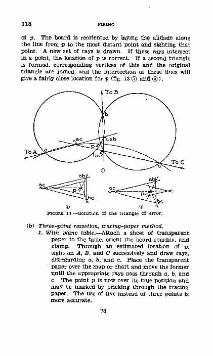
118 FIRING
of p. The board is reoriented by laYing the alidade along the line from p to the most distant point and sighting that point. A new set of rays is drawn. If these rays intersect in a point, the location of p is correct. If a second triangle is formed, corresponding vertices of this and the original triangle are joined, and the intersection of these lines will give a fairly close location for p (fig. 13 <D and ®).
ac
FIGURE 13.-Solutlon of the triangle of error.
(b) Three-point resection, tracing-paper method. 1. With plane tabZe.-Attach a sheet· of transparent
paper to the table, orient the board roughly, and clamp. Through an estimated location of p, sight on A, B, and C successively and draw rays, disregarding a, b, and c. Place the transparent paper over the map or chart and move the former until the appropriate rays pass through a, b, and c. 'rb.e point p is now over its true position and may be marked by pricking through the tracing paper. The use of five instead of three points is more accurate.
78
FIRING 118-119
2. With instrument.-The angles between the distant points may be measured with an aiming clrcle or other angle-measuring instrument and plotted on transparent paper. This is not as accurate as direct sighting, since to the errors of the instrument those of plotting are added.
(c) Back-azimuth method.-This method requires an accurately declinated angle-measuring instrument and three distant visible points located on the map or chart. The back azimuth of a given line is the azimuth plus 3,200 mils. Set up a declinated instrument at the point to be located and measure the Y -azimuth of each of the three distant points. Add 3,200 mils to each Y -azimuth and through each plotted point draw a ray having its proper back azimuth. The intersection of the rays will be the location of the station P. This is the only method that can be used when P is on the circumference of a circle passing through A, B, and C .
• 119. TRIGONOMETRIC METHODS.-a. General.-When time and equipment are available and when other conditions warrant the degree of accuracy sought, survey locations in battalion and higher units should be obtained by instrument readings and computation rather than by graphical methods. Either a transit or an aiming circle may be used. The computation may be with logarithm tables or with the slide rule. To avoid gross errors, the following checks should be incorporated in every survey:
(1) All traverses should be closed. (2) When establishing vertical control, the mean of fore
sight and backsight readings should be used when possible. (3) When using a transit to obtain the distance to a far
point, two triangles having a common side, which is the distance desired, should be established and solved for the common side. The two results should not vary more than 0.5 percent (5 yards per thousand). The bases of the triangles should be of such length and direction that the angle subtended by each at the inaccessible point will be at least 50 mils (3•).
(4) When using an aiming circle to obtain the distance to a far point, one triangle ordinarily is solved. The base
79

119 FIRING
should be of such length that the angle in mils subtended by it at the far point will be, numerically, at least 4 percent of the range to the far point.
(5) Whenever possible, the angles at the ends of a base should be read cumulatively three to six times, and the average used.
b. Solution of the right triangle.-(!) The following trigonometric formulas are used in the solution of right triangles (fig. 14) :
c= v a"+b'
Sin A=•~ c
Cos A=~ c a
TanA=b
Y-north
~~--------b---------J,c
FIGURE 14.-The right triangle.
(2) If the coordinates of two points, A and B, are known, a right triangle may be formed with the line joining the two points as the hypotenuse. By using the appropriate formulas above, the Y -azimuth of the line joining the points and the distance between them can be found. In figure 14, the difference of the X-coordlnates of points A and B would be the side b of the triangle and the difference of the Y -coordinates the side a.
(3) Conversely, if the distance between two points A and B, the Y -azimuth of the line AB, and the coordinates of one of the points are known, the coordinates of the second point can be found by solving the right triangle for the two sides,
80
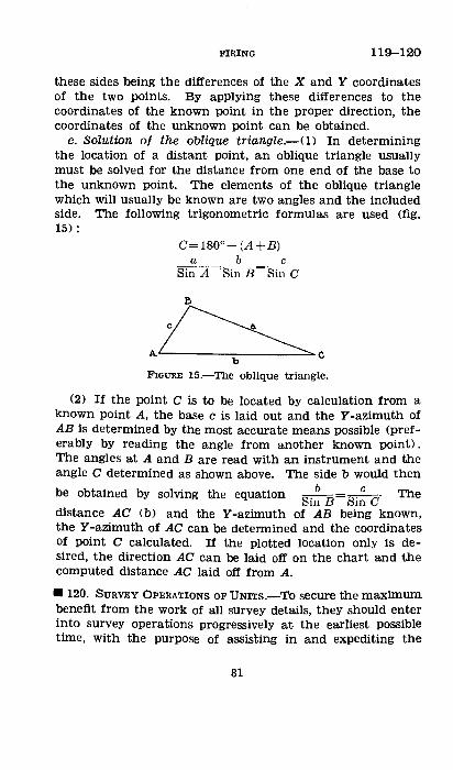
FIRING 119--120
these sides being the differences of the X and Y coordinates of the two points. By applying these differences to the coordinates of the known point in the proper direction, the coordinates of the unknown point can be obtained.
c. Solution of the oblique triangle.-<1) In determining the location of a distant point, an oblique triangle usually must be solved for the distance from one end of the base to the unknown point. The elements of the oblique triangle which will usually be known are two angles and the included side. The following trigonometric formulas are used (fig. 15):
0=180°-(A+B) a b c
Sin A =sin B=Sin C
l>
A~c b
F'IGUIIE 15.-TI:te obllque triangle.
(2) If the point C is to be located by calculation from a known point A, the base c is laid out and the Y -azimuth of AB is determined by the most accurate means possible (preferably by reading the angle from another known point). The angles at A and B are read with an instrument and the angle C determined as shown above. The side b would then
be obtained by solving the equation b c Th Sin B=Sin c· e
distance AC (b) and the Y-azimuth of AB being known, the Y-azimuth of AC can be determined and the coordinates of point C calculated. If the plotted location only is desired, the direction AC can be laid off on the chart and the computed distance AC laid off from A .
• 120. SURVEY OPERATIONS OF UNITS.-TO secure the maximum benefit from the work of all survey details, they should enter into survey operations progressively at the earliest possible time, with the purpose of assisting in and expediting the
81
120 FIRING
delivery of coordinated fire. Each echelon should cooperate so as to produce effective and timely control. Lower units should be aided and not delayed by the survey work of higher units. By a well thought out plan, survey will be accomplished with a minimum of confusion and loss of time.
a. Brigade.-U) General.-Survey by the brigade to coordinate regimental and battalion survey should start as soon as occupation of the area is contemplated. It should be carried on aggressively so as to provide a framework on which lower units may base their survey operations. It must provide sufficient control so that the positions will be occupied and fire delivered in furtherance of the division plan. It must provide the coordination necessary to concentrate the fire of the brigade where and when called for.
(2) Orientation.-The survey operations of the lower units of the brigade should be coordinated by a brigade orienting system. At the earliest possible time, the nature of this system and the accurate locations of useful points for registration, reference, and control should be furnished the regiments. This information should be made available by the time the survey parties of the lower units arrive in the brigade area.
b. Regiment.-U) General.-Survey by tl;le regiment to coordinate the battalions should start when information is received from the brigade commander tha't occupation of a position area is contemplated. Regimental survey details should go forward as soon as possible in order to assist the brigade survey officer. All information received by the regiments should be sent to battalions without delay in order to preven't duplication of effort and to furnish early coordination between units.
(2) Orientation.-As soon as the brigade survey plan has been determined, regimental details should begin the establishment of control in each battalion area. Battalion survey details move forward as soon as possible in order to complete 'the work necessary to coordinate fire.
c. Battalion.-U) General.-Surveys by the battalion to coordinate battery surveys should be begun by reconnaissance details as soon as it is known a position is to be occupied, and should be improved constantly, This work
82

FmiNG 120
must not interfere with rapid preparation and immediate opening of fire when the tactical situation so demands.
(2) Initial orienting point.-<a> With a map.--Select an accessible point from which at least one other known point can be .seen. The selected point may be one that can be located on the map by direct identification or a resection may be necessary to determine its map location.
(b) Using a mosaic.-An initial orienting point is selected which surely can be identified on the photo.
(c) Using an extemporized chart.-When no horizontal control has been furnished by higher units, the initial orienting point and orientation are chosen arbitrarily so that the battalion area will be included on the chart. Arbitrary coordinates are assumed for the orienting point and a definite direction is assigned an arbitrary Y -azimuth. These values are sent to batteries so that all grids in the battalion will be coordinated.
(d) Altitudes.-If no vertical control is available, an altitude which will give no negative values is assumed for the initial point. Other altitudes are then determined from site readings.
(3) Orienting line (par. 124e) .-(a) The pieces of each battery should be visible from, and within calling distance of, one or more points on the orienting line. When practicable, one orienting line is used for all batteries in the battalion.
(b) Under favorable conditions of terrain, an orienting line through the base piece and the base point will give excellen't results. Often by taking an instrument up the .slope in front of or behind the guns, the base point can be seen. Upon lining in the instrument on the line base piecebase point, this line can be staked out (par. lOlb). In this case an orienting line for each battery may be used.
(c) stakes marking the orienting line are placed so that at least one stake or other point on the orienting line can be seen from any point <on the line) that is to be used. Stakes are carefully alined, firmly driven, marked for identification, and protected from disturbance.
(d) An orienting line permits greater uniformity of laying than does a compass needle. When one orienting line is used by all batteries or when all orienting lines are tied in to
83
120 FIRING
one control net, corrections found by adjusting one piece may be used by all batteries.
(4) Place marks.-A place mark, usually a stake firmly planted, tagged for identification, and marked with the coordinates and altitude, is located by the battalion reconnaissance officer, often by traverse from the initial orienting point. A place mark must be near the battery position, preferably visible from the base piece, and, if possible, on the orienting line.
(5) Observation posts.-The battalion observation post and generally one or more auxiliary (lateraD observation posts are located by the most accurate means available. These points are chosen with a view to the location of reference points, base points, check points, and targets, and for the observation of fire.
(6) Points tor registration, reference, and controZ.-Reference points, base points, and check points are located accurately by intersection or other means from two or more known points. When points are to be located by restitution from aJr photos, two or more points which can be identified on the photos must be located on the chart.
(7) Declinating station.-A declinating station is a point, free from local magnetic attraction, marked by a stake, with lines of determined Y -azimuth radiating from the point and marked on the ground by stakes. The lines should pass through well-defined distant objects. Such a station is necessary if instruments are not already declinated.
(8) Information for the batteries.-At the earliest possible time, each battery is furnished the following information: the location and Y -azimuth of the orienting line; the location of the battery place mark with its coordinates and altitude; the location of the declinating station; the locations of the reference point, base point, and targets; when there is no map, the coordinates to use for tne southwest corner of the grid sheet.
d. Battery.-(!) General.-The survey work of the battery is a continuation of that of the battalion. In the absence of a battalion survey, the battery will locate the piece position, observation post, and other important points in the
84
FIRING 120-121
manner indicated for the battalion in locating place marks and other points.
(2) Location.-The coordinates and altitude of the base piece are determined from the place mark, usually by traverse. Other pieces of the battery are located with reference to the base piece.
(3) Night occupation.-The positions of pieces and of the executive's instrument are determined and marked by stakes during the hours of daylight and prior to the occupation. Means to lay the battery promptly upon arrival must be provided.
e. Orientation ot observing instruments.-If registrations or adjustments are to be made during darkness, all observing instruments, battalion and battery, should be laid during daylight by the best means available, and a means for their orientation during darkness must be provided. For combined observation, the instruments should be laid with respect to a definite point in the target area <usually a base point) and preferably sighted upon it.
•121. SURVEY PLANS.--<1.. (1) The brigade commander, in formulating his survey plan with the assistance of the brigade survey officer, must consider the division plan of action and the part the artillery is to play in furtherance of the division mission. He must decide-
(a) What type of map or map substitute is to be used as a firing chart for the units of the brigade.
(b) How much survey is necessary to accomplish the artil-lery mission.
(2) In general the brigade survey detail should locate(a) An initial orienting point in each regimental area. (b) Points suitable for registration, reference, and control. (3) If time permits and the regimental and battalion sur-
vey details are available, complete survey should be accomplished before the arrival of the batteries in the position area.
(4) The brigade survey officer should continue to coordinate and to improve the survey of the units of the brigade as long as the positions are occupied. He should continue to locate distant points in front of and in rear of positions of
85
121 FffiiNG
units of the brigade so as to be ready for displacement either to the front or to the rear.
(5) If possible, an orienting line, or lines, should be established by the brigade survey officer for the coordination of the various units.
b. The regimental commander with his survey officer must . plan to carry forward with dispatch the control needed by the battalions. Initial points, if not provided by brigade, must be established by regimental survey. From these points the regiment must provide at least one point for each battalion.
c. (1) The battalion commander, in formulating his survey plan with the assistance of his reconnaissance officer, must consider the complete battalion survey, with base pieces, observation posts, visible reference points, suitable base point or points, and control points by which targets may be restituted-all accurately plotted to a known scale in their proper relation one to the others. He must decide-
(a) How much of the complete survey is necessary to accomplish the mission.
(b) How much of that which is required is already at hand in the form of topographic data previously plotted.
(2) The following considerations have a direct bearing on his survey plan:
(a) Mission of the battalion. (b) Maps, photos, and other topographic information avail
able. (c) Whether registration is unlimited, limited, or pro
hibited by weather, battle conditions, or orders. (d) Whether adjustments requiring accurate orientation
of observing instruments are anticipated. (e) Time available for survey. (3) The instructions of the battalion commander may
include-(a) What is to be used as a firing ehart; map, mosaic, or
grid sheet. ' (b) Whether battery survey details will work directly under
the battalion reconnaissance officer or independently. (c) Identification on the ground of base, check, and refer
ence points.
86
FIRING 121-124
(d) Which survey requirements are to be given priority, both as to time and accuracy .
• 122. PRIORITY AND PROCEDURE.-Survey is of major importance in assuring the delivery of accurate fire at all times regardless of darkness, fog, or other unfavorable weather conditions, and when registration is restricted or prohibited. The procedure and priority of survey operations vary with the kind and amount of topographic data already at hand and with the mission; that is, whether observed-fire or unobserved-fire mission will be required and whether registration is unrestricted, restricted, or prohibited. Regardless of the initial type of firing chart and initial survey operations, a complete survey should eventually be made and a complete firing chart constructed.
SECTION V
PREPARATION OF FIRE FROM FIRING CHARTS
• 123. GENERAL.-This section includes the determination of basic data from firing charts and the correction of data for conditions not standard. Generally, data taken from a firing chart, whether the chart consists of a map, a mosaic, or an improvised chart, are described by the term map, as map data, map range, map shift, and so on.
•124. DEFINITIONs.--a. Basic data are the uncorrected direction, distribution, site, and range determined from a firing chart .
. b. The base point is a well-defined point, accurately located on the firing chart, and uSed as an origin for shifts. Usually it is registered upon.
c. The base piece is the piece, normally No. 1, for which initial data are computed, and with reference to which data for the other pieces are determined.
d. The base line is the line joining the base piece and the base point, or is a line of known direction (for example, compass 4,000) passing through the base piece, used as an origin for shifts.
87
124-125 FIRING
e. An orienting line is a line of known direction marked on the ground and plotted on the firing chart, used to obtain initial direction by means of a base angle.
f. The base angle is the clockwise angle from the base line or gun-target line <extended when necessary) to the orienting line.
g. A check point usually is a visible point on which an adjustment is made to correct data for subsequent firing; it may be a center of impact or burst center of a number of rounds fired with the same data. A base point may be used as a check point.
h. A reference point is an unmistakable object used to identify less prominent objects by describing their relation to, or angular direction from, the reference pOint.
i. A check concentration is a concentration (or fire) prepared upon a terrain feature previously selected, for the purpose of assisting a forward observer (or liaison officer) to identify targets in its vicinity and to bring fire to bear upon them (par. 137 e).
i. Registration is an adjustment on a base point or on a check point. The results of the registration are used to determine corrections in direction and range .
• 125. DETERMINING BASE DEFLECTION.-The deflection to establish the base piece on the base line is determined by one of the following methods:
a. Without registration.-In the absence of registration, the base piece is laid on the base line with survey data determined from the firing chart (par. 126 a).
b. Registration.-The base piece having been registered, the recorded base deflection may be one of the following, depending on whether the basic data are to be corrected for drift only, for wind and drift, or neither:
(1) When only observed fires are to be delivered, no corrections for w:ind or drift are necessary and the adjusted deflection is recorded as base deflection.
(2) When x·-transfers are to be delivered, the basic data for targets are corrected for drift; hence the drift correction is removed from the adjusted deflection before recording base deflection.
88
FIRING 125-126
(3) When fire with map data corrected is to be delivered, the basic data for targets are corrected for wind and drift; hence corrections for wind and drift are removed from t.he adjusted deflection before recording base deflection.
• 126. BASIC DATA.-a. Directiorn.-(1) Direction to lay the base piece on the base point may be determined as a: Y -azimuth; as a base angle; or, if an aiming point is located accurately on the firing chart, as a firing angle, which is converted to deflection.
(2) Direction to lay the base piece on a target may be determined in any of the foregoing ways, but usually is determined as the map shift from the base line to the target. When the target is shown on the firing chart as an area, the map shift is measured from the base line to the right edge of the area. When only the center of the target appears on the firing chart, the map shift is measured to that point, and the additional shift necessary to place No. 1 piece on the right edge of the target area is computed by the mil relation. Direction usually is measured with a protractor. However, when the accurate coordinates of the piece, base point, and target or aiming point are known, the ¥-azimuth of each side of the angle sought may be computed trigonometrically and the angle determined from the difference of the Y -azimuths.
b. Distribution.-Distribution and method of fire are calculated from the measured front of the target as prescribed in paragraph 102.
c. Site.-Altitudes of the piece and target are determined from a contoured map, if one is available; otherwise the relative altitudes are determined by site readings or by estimation.
d. Range.-Range usually is measured with a plotting scale. When the chart is of a different scale than the plotting scale, the measurement is converted to yards by applying to the measured range the factor, true distance;chart measurement. When the accurate coordinates of the piece and target are known, the range may be computed.
e. Minimum elevation.-When a contoured map is available and the map location of the battery is known, minimum elevation may be computed. From the relative altitudes of the
89
126-128 FIRING
base piece and the mask and the range to the mask, the site of the mask is computed. Allowance must be made for height of trees on the mask when computing its site. The remainder of the operation is given in paragraph 109. The determination of dead space is covered in paragraph 213.
•127. CoRRECTIONS.-<£. When fire can be observed and adjusted on a target, it is not necessary that the basic data be corrected for conditions of weather and materiel, as these corrections are applied by the adjustment itself. However, when time and facilities permit, it is desirable that adjustments be started with corrected data in order to conserve time and ammunition. When fire cannot be adjusted on a target (for example, observation impossible, or surprise effect desired) the basic data must be corrected for conditions not standard.
b. When registration is not permitted or cannot be accomplished, the base piece is laid on the base line by survey methods and the basic data are corrected by computation for conditions not standard (par. 81 d). Data corrected in this manner are called map data corrected. For method of calculating map data corrected, see Firing Tables and FM 6-130.
c. A transfer of fire consists of registration on a point whose position relative to the piece and targets is known, and the determination from this registration of corrections to be applied to the basic data for the targets. The method of transfer depends on whether map data~ corrected have been computed for the targets. If map data corrected have been prepared, VE-transfers (par. 131> may be used; if not, Ktransfers are used.
•128. K-ThANSFER OF FIRE.-<£. General.-<1> A K-transfer of fire consists of, first, registration on a check point <usually the base point) to establish the base piece on the same line and to determine a range correction factor <K> ; and second, correction of the map range of the target by use of the K.
(2) Conditions favorable to K-transfers are as follows: (a) The deflection for the target should be within 300 mils
of that for the check point; the range should be between 3/4 and 4/3 of the range of the check point. These limits are termed transfer limits.
90
FIRING 128
<b> Fire on the target should follow the adjustment on the check point as soon as possible.
(c) The adjustment on the check point and the fire on the target must be with the same kind and weight of projectile, the same fuze, and the same charge and powder lot.
b. Dire:ction.-The object of registration as regards direction is to establish the base piece on the base line. Base deflection, when recorded as a result of registration and for use with K-transfers, includes corrections for wind and errors of survey. In K-transfers it is assumed that these corrections are constant for all targets within transfer limits.
(1) Registration on the base point.-When registration is on the base point, the adjusted deflection forK-transfer use is modified by shifting right the amount of drift at base-point range. This allows the correction for drift for any subsequent target to be applied in full. The sheaf is then adjusted or formed parallel and base deflection recorded.
Example: No. 1 piece has been adjusted on the base point. The drift at the range of the base point is 4 mils. Following the adjustment, the base piece is established on the base line by the following commands:
RIGHT 4. ON NO. 1 ADJUST SHEAF PARA!.LEL. 4,000. RECORD BASE DEFLECTION.
(2) Registration on a check point.-In cases where it is impossible to adjust on the base point or where the targets to be fired on are outside of transfer limits from the base point, it is necessary to adjust on a check point. In this case, base deflection has been determined and recorded by any available means, and the purpose of the adjustment is to correct base deflection for wind and other unknown effects. The correction is equal to the difference between the adjusted deflection and the initial deflection. It is applied by shifting from base deflection the amount of the correction and recording a new base deflection. The initial deflection shift to the check point is the map shift modified by the drift correction at check-point range; since drift is to the right, the drift correction is to the left.
91
128 FIRING
Example: Map shift to check point __________ base deflection left 200 Drift correction at range to check point ____________ left 4 Initial deflection shift_ ___________ base deflection left 204 Adjusted deflection to check point __ base deflection left 211 The correction is left 7. The direction of the battery is
corrected by the following commands: BASE DEFLECTION LEFT 7. RECORD NEW BASE DEFLECTION.
(3) Initial dettection shift to a target.-New base deflection having been recorded, the map shift from the base line to the target is measured. The map shift, modified by the drift correction at target range is the initial deflection shift. The error of the initial base deflection is taken care of by the recording of the new base deflection.
Example: Map shift_ _____________________ base deflection right 200 Drift correction at target range ____________________ left 5 Initial deflection shift_ ___________ base deflection right 195 c. Range.-In K-transfers it is assumed that, within trans-
fer limits, adjusted ranges (less site) are proportional to the corresponding map ranges. Hence,
Target initial range Check-point adjusted range Target map range Check-point map range
Check-point adjusted range The factor . is known as K. Check-pomt map range
Hence, the initial range for the target=KXtarget map range. K may be expressed as a decimal or as a correction of plus or minus so many yards per thousand.
d. Determination of K.-The factor K may be determined as a decimal by dividing the adjusted range by the map range; or as a correction, expressed as so many yards per thousand by dividing the difference between the adjusted range and the map range by the map range in thousands of yards.
Example: Map range of check point_ __________________ 4, 460 yards Elevation for map range of check point______ 159. 5 mils Site of check point------------------------- +2. 8 mils
92
FIRING 128
Initial quadrant elevation <75-mm gun, M1897, shell Mk. I, fuze quick (long)----------------- 162. 3 mils
Adjusted quadrant elevation________________ 170. 0 mils Using the above data, K may be calculated by either of
the following methods: (1) By relation ot ranges.-This is usually the most pre
cise method. Adjusted quadrant elevation________________ 170. 0 mils Site <to be subtracted)--------------------- +2. 8 mils
Adjusted elevation__________________________ 167.2 mils Adjusted range (from Firing Tables) ________ 4, 584 yards
4,584 K= 4,460=1.028, or +28 yards per thousand.
4,584-4,460 124 Or, K 4.46 + 4.46 =+28 yards per thousand.
(2) By relation ot quadrant elevations.-When initial data for the base or check point are computed from the firing chart prior to adjustment, it is more convenient to calculate K by the relation of quadrant elevations as shown below for the above example:
Adjusted quadrant elevation________________ 170. 0 mils Initial quadrant elevation___________________ 162. 3 mils
Difference__________________________________ +7. 7 mils Range change for one-mil elevation change at
map range of check point (Firing Tables)__ 16 yards Range correction ( +7.7X 16) ---------------- +123 yards
+123 K= 4.46 =+28 yards per thousand.
e. Application of K.-After K is determined, it is applied to map ranges to determine initial ranges. When map data have been computed and uncorrected quadrant elevations determined, the range correction is converted to mils by dividing it by the range change for a 1-mil elevation change at the map range of the target <determined from Firing Tables).
Example: 75-mm guns, M1897, firing shell Mk. I, fuze quick (long). K has been determined as plus 30 yards per
177568"-39--7 93
128-129 FIRING
thousand (or as 1.030) . It is desired to fire , on a target at a map range of 4,920 yards and a site of rf-4.8 mils. The range correction can be applied in either of two ways, as follows:
(1) By deterrnining a corrected range.-The initial range is 4,920Xl.030=5,068 yards; or 4,920+C30X4.9> =5,067 yards. The initial quadrant elevation is 200.4 mils plus a site of +4.8, or 205 (205.2) mils.
(2) By deterrnining an elevation correction.-The uncorrected quadrant elevation is 190.0 (elevation for 4,920 yards) plus site ( +4.8), or 194.8 mils. The, range correction is +30X4.9 or 147 yards. The range change for a 1-mil change of elevation at 4,900 yards is 14 yards. The ,elevation correction is 147/14 or 10.5 mils. The initial quadrant elevation is 194.8 mils plus 10.5 mils, or 205 (205.3) mils .
• 129. MAP DATA CORRECTED.-a. General.-The nonstandard conditions for which corrections are made (par. 127b) include weather conditions as given by the metro message, temperature of powder, weight of projectile, and velocity error CVE). Detailed in.struetion.s for determining these corrections are given in the Firing Tables.
b. Velocity error.-(1) The velocity error VE is a value found from registration, the effect of which, when combined with the effects for known conditions affecting range, makes the computed range agree with the a,djusted range of the registration. This value is the combined effect of variation of muzzle velocity from standard, variation of materiel and weather conditions from the values used in the computation, and errors of locating the piece and the target. Muzzle velocity is assumed to be the element most in error, and VE is computed as if the difference between adjusted range and corrected range were due to variations of muzzle velocity alone.
(2) When a lTE is determined by registration, this value of VE is used in correcting the data for fires until there is an appreciable ch~mge in weather conditions. Otherwise, the value of VE is taken as the mean of several VE's obtained with the same powder lot and from the same position.
(3) VE is determined as follows:
94

FIRING 129-130
(a) Subtract the initial range from the adjusted range. This gives the range correction. Change the sign and divide the result by the effect of a 1-foot change in muzzle velocity at the map range; this gives the velocity error <VE). The initial range includes corrections for all known effects of weather and materiel.
Example: 75-mm gun, M1897, firing shell Mk. I, fuze quick (long).
Map range (5,150) +corrections for known conditions of weather and material ( + 100) =initial range (5,250).
Adjusted range (5,300) -initial range (5,250) =correction <+50); effect=-50.
Velocity error (VE) range effect = -50=_25 range effect of 1 f/s 2.0
foot-seconds. (b) The known effects of weather and materiel originally
corrected for may have included an old VE. On completion of the registration, a value of VE is determined as in (a)
above. If an old VE was included, the result obtained after registration is a VE-change; it is the difference between the VE used in calculating the initial data and the total VE which must be used to obtain the adjusted data. The VE which must be used in subsequent fire on targets is the algebraic sum of the VE-change obtained from registration and the VE used in calcUlating the initial range for the check point. If no old VE was included in the known effects of weather and materiel on the check point, the value of the VE obtained as in the example above is used as the VE. In computations for future targets, the value of VE is applied as
· an effect. In the example above, as the initial range was less than the adjusted range, the sign of the VE-effect was minus and the sign of the correction will be plus .
• 130. WEATHER-CORRECTION DIAGRAM.-{l. When Weather corrections are to be determined for a number of concentrations, a weather-correction diagram may be constructed, usually after the receipt of each new metro message, Rays are draWn through the plotted position of the base piece at intervals of 400 mils, sufficient in number to include the target area. The necessary computation is simpler when these rays are drawn
95
130-131 FIRING
to coincide with exact hundreds of Y-azimuth. When the targets occupy a sector less than 200 mils wide, the diagram may be reduced to a single ray through the center of the target area.
b. Corrections are' computed for materiel, weather, and VE for the portion of each ray in the target area at intervals of 2,000 yards. Basic data for each check point and target should include drift correction and site; hence these corrections do not appear on the diagram.
c. Corrections for each thousand yards of range along rays 100 mils apart are determined by interpolation, and, from these, corrections for specific targets are determined by inspection. These corrections usually are determined to the nearest mil.
•131. VE-TRANSFER.-A VE-transfer is a transfer based on map data corrected, to which have been applied corrections determined by a registration immediately prior to firing on targets. This must not be confused with map data corrected, which may include an old VE or the me!:,n of .several old VE's. The conditions favorable for a VE-transfer are, in general, the same as for a K-transfer (par. 128 a (2)).
a. Use.-The VE-transfer is most commonly used when map data corrected have been computed for the check point and a number of targets prior to registration. Upon registration, the VE-change determined therefrom (par. 129 b (3) (b)) is computed and is used to determine corrections for the data already computed for the targets.
b. Dettection.-In registration upon a check point, which · may be the base point, to determine a new base deflection suitable for use with VE-transfers to follow immediately, the initial deflection for the check point should include corrections for drift and wind. The difference between the adjusted deflection and the initial deflection is the correction due to unknown causes. This correction is applied to the base deflection to obtain the new base deflection in the same manner as for a K-transfer (par. 128 b (2)).
Example correcting base deflection by adjustment on a check point:
96
FIRING 131
Map shift to check point _________ base deflection right 100 Drift correction for check point_ ____________________ left 4 Wind correction (calculated from metro message) ____ left 5
Initial deflection __________________ base deflection right 91 Adjusted deflection _______________ base deflection right 88 The correction for unknown conditions is left 3; the direc-
tion of the battery is corrected by the command: BASE DEFLECTION LEFT 3. RECORD NEW BASE DEFLECTION.
c. Direction for targets.-Wind and drift corrections are computed from Firing Tables for each target and are applied to the map shift.
d. Range.-Following registration, a VE is determined as in paragraph 129 b (3). When map data corrected have been computed for targets prior to registration, only the VEchange is applied as an additional correction, because any VE in use before registration already has been applied to the data for the targets. If map data corrected have not been computed, the algebraic sum of the old VE and the VEchange (par. 129 b (3)) is used when computing the corrections to be applied to the basic data for the targets.
Example: 155-mm howitzer, firing shell Mk. I, charge V, fuze quick (long). Registration on a check point with map data corrected, including an old VE of -20 f/s, gives a VEchange of -13 f/s. · Map range of target_ _____________________ :.. ___ 6, 800 yards Corrections for known conditions of weather and
materiel (including old VE of -20 fjs) _______ +165 yards
Initial range for target (before registration)---- 6, 965 yards Effect of one-foot change in muzzle velocity at
map range_________________________________ 7. 8 yards Effect of VE-change of -13 f/s ( -13 X 7.8) _____ -101 yards Correction ____________________________________ +101 yards
Initial range for target after registration (6,965+101) -------------------------------- 7, 066 yards
If map data corrected had not been computed for the target prior to registration, the VE-effect on the target would have been obtained by using a VE of -33 f/s ( ( -20) + ( -13) ) .
97

132 FIRING
• 132. DISCUSSION OF CORRECTIONS.--a. When time permits and a metro message is available, weather corrections are prepared. EVen when registration is permitted by orders, the corrections are prepared in advance, as registration often cannot· be accomplished because of the lack of visibility or the amount of firing in the area.
b. In choosing between K- and VE-methods of transfer, the following considerations are applicable:
(1) K-transfers are easier to compute, hence will result in fewer errors of computation.
(2) The VE-method is more accurate for direction. When the cross-wind effects are large and K-transfers are used, corrections for cross wind may be applied as in VE-transfers or direction may be checked by a high burst (par. 133).
(3) Within transfer limits, the K-transfer is about as accurate in range as the VE-transfer, particularly at midranges.
c. With separate-loading ammunition, the problem of correcting the data should be one of the considerations when determining the number of different charges to be used. If several charges are necessary, it may be easier to compute map data corrected for each target rather than for one or more rays across the firing area. The K determined for one charge is of little value for correcting data using other charges. The VE determined for one charge will not give accurate results with another charge, but is used if necessary. The degree of accuracy that can be expected from using aVE for charges other than the one used in the check adjustment must be based on experience with the particular type of weapon and ammunition.
d. When registration is limited to one battery per battalion, all batteries are laid by the same survey data, usually an orienting line, and base deflections are recorded. Upon completion of the registration, the adjusting battery reports its deflection correction and the K or VE determined. The remaining batteries apply the deflection correction to their base deflections and use the reported K or VEin determining their range corrections.
98

FIRING 133-135
• 133. ADJUSTMENT FOR DIRECTION BY HIGH BURSTS.--a. General.-The direction of fires against targets on which adjustment cannot be made may be checked and corrected by firing a time-fuzed round in the direction of the target and observing the error of this round with an observing instrument at the battery position. The instrument usually is placed near the base piece and in this case may be assumed to have the same map location as the base piece. The procedure consists of, first, recording instrument direction, that is, establishing the 0-3,200 line of the instrument on the base line (par. 74); and second, correcting direction for targets.
b. Correcting direction for targets.-The instrument direction of the base point being zero, the instrument direction .for a target is the map shift from the base line to the right edge of the target. This is announced as "Instrument direction right (lett> (so much)," followed by the range or elevation setting. For ammunition using fuzes which are set for time and corrector, the time also is announced. The range setting or time is determined from the Firing Tables. The procedure followed by the executive is described in paragraph 74.
c. Frequency of checking.-It is not necessary to check direction on every target. Usually, when a number of concentrations are to be fired in a limited area within a short period of time, the executive checks direction on the first one to be fired and applies the correction determined to the remaining missior:s.
SECTION VI
SCHEDULE FIRES
• 134. DEFINITION.-Schedule fires are planned fires executed according to a time schedule or upon signal or call from the supported troops (pars. 138 and 204).
•135. TYPEs.-As to method of delivery, a schedule fire is either fire on an area or fire on a line. Fire on an area is a concentration; fire on Et line is a barrage. Terms such as counterbattery, neutralization, harassing, etc., applied for
99
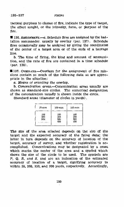
135-137 FIRING
tactical purp'oses to classes of fire, indicate the type of target, the effect sought, or the intensity, form, or purpose of the fire.
• 136. AssiGNMENT.-a. Schedule fires are assigned by the battalion commander, usually by overlay (par. 137). Schedule fires occasionally may be assigned by giv:lng the coordinates of the center of a target area or of the ends of a barrage line.
b. The time of firing, the kind and amount of ammunition, and the rate of fire are contained in a time schedule (par. 138).
•137. OVERLAYs.--Overlays for the assignment of fire missions contain so much of the following data as are appropriate in the situation:
a. Means of orienting the overlay. b. Concentration areas.--Concentration areas usually are
shown as standard-size circles. The numerical designation of the concentration usually is shown inside the circle.
Standard areas (diameter of circles in yards) .
75-mm
100 200 300
105-mm
100 200 300 400
155-mm
100 200 300 400
The size of the area selected depends on the size of the target and the expected accuracy of the firing data; the latter in turn depends on the accuracy of location of the target, accuracy of survey, and whether registration is accomplished. Concentrations may be designated by a cross; which marks the center of the area and a symbol which shows the size of the circle to be used. The symbols are P, Q, R, and S, and are an indication of the estimated accuracy of location of a target, signifying accuracy to within 50, 100, 150, and 200 yards, respeetively. Accordingly,
100
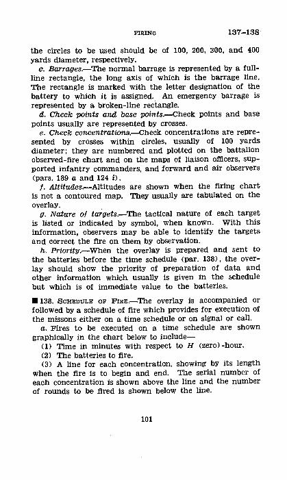
FIRING 137-138
the circles to be used should be of 100, 200, 300, and 400 yards diameter, respectively.
c. Barrages.-The normal barrage is represented by a fullline rectangle, the long axis of which is the barrage line. The rectangle is marked with the letter designation of the battery to which it is assigned. An emergency barrage is represented by a broken-line rectangle.
d. Check points and base points.--Check points and base points usually are represented by crosses.
e. Check concentrationsi.--Check concentrations are represented by crosses within circles, usually of 100 yards diameter; they are numbered and plotted on the battalion observed-fire chart and on the maps of liaison officers, supported infantry commanders, and forward and air observers (pars. 189 a and 124 i) .
/. Altitudes.-Altitudes are shown when the firing chart is not a contoured map. They usually are tabulated on the overlay.
g. Nature of targets.-The tactical nature of each target is listed or indicated by symbol, when known. With this information, observers may be able to identify the targets and correct the fire on them by observation.
h. Priority.-When the overlay is prepared and sent to the batteries before the time schedule (par. 138), the overlay should show the priority of preparation of data and other information which usually is given in the &chedule but which is of immediate value to the batteries.
• 138. SCHEDULE OF FIRE.-The overlay is accompanied or followed by a schedule of fire which provides for execution of the missons either on a time schedule or on signal or call.
a. Fires to be executed on a time schedule are shown graphically in the chart below to include-
(!) Time in minutes with respect to H <zero) -hour. (2) The batteries to fire. (3) A line for each concentration, showing by its length
when the fire is to begin and end. The serial number of each concentration is shown above the line and the number of rounds to be fired is shown below the line.
101
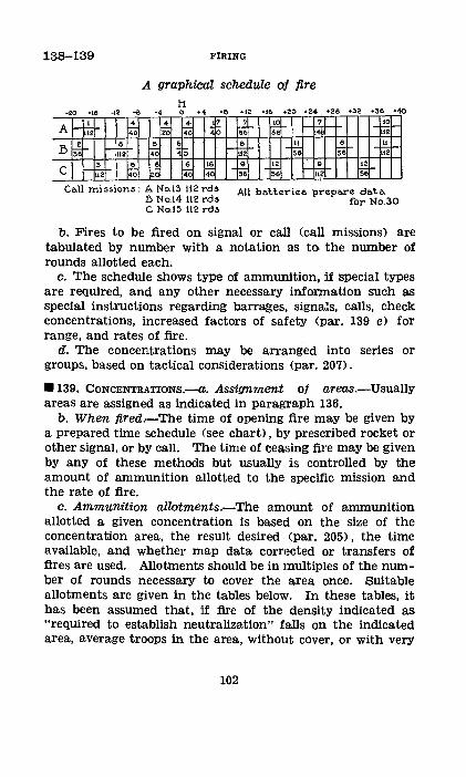
138-139
·20 ·10 -1 2 -a
A ~ 4
40
B s~ f-~ c i-F, 6
u2 40
FIRING
A graphical schedule of fire
-~ 20
~ 40
6 iii
li 0
4
40
5
0
6 40
. +6 +12 +!6 +20 +24 +28 +~2 +36 +40
7
~ 10 t-' ~
40 5 • 12
~ ~ 56 ~ 56
~ U2
~ ~ 12 t-• ~ 140 56 56 112 56
Call missions: A No.!~ 112 rds All batteriea prepare data I~ No.l4 112 rds for No.30 C No.15 112 rds
b. Fires to be fired on signal or call (call missions) are tabUlated by number with a notation as to the number of rounds allotted each.
c. The schedUle shows type of ammunition, if special types are required, and any other necessary information such as special instructions regarding barrages, signals, calls, check concentrations, increased factors of safety (par. 139 e) for range, and rates of fire.
d. The concentrations may be arranged into series or groups, based on tactical considerations (par. 207).
• 139. CoNCENTRATIONs.-.a. Assignment ot areas.-Usually areas are assigned as indicated in paragraph 136.
b. When fired.-The time of opening fire may be given by a prepared time schedule <see chart), by prescribed rocket or other signal, or by call. The time of ceasing fire may be given by any of these methods but usually is controlled by the amount of ammunition allotted to the specific mission and the rate of fire.
c. Ammunition allotments.-The amount of ammunition allotted a given concentration is based on the size of the concentration area, the result desired (par. 205), the time available, and whether map data corrected or transfers of fires are used. Allotments should be in multiples of the number of rounds necessary to cover the area once. Suitable allotments are given in the tables below. In these tables, it has been assumed that, if fire of the density indicated as "reqUired to establish neutralization" falls on the indicated area, average troops in the area, without cover, or with very
102
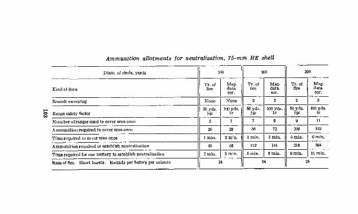
.... 0 tA)
Ammunition allotments tor neutralization, 75-mm HE shell
Diam. of circle, yards 100 200
Tr. of Map Tr. of Map Kind of data fire data fire data
cor. cor. --------
Rounds sweeping None None 2 2 -------- --------
Range safety factor 50 yds . 100 yds. 50 yds. 100 yds. ~c 1c ~c 1c
Number of ranges used to cover area once 5 7 7 9
Ammunition required to cover area once 20 28 56 72
Time required to cover area once I min. 2min. 3min. 3min.
Ammunition required to establish neutralization 40 56 112 144
Time required for one battery to establish neutralization 2min. 3min. 5min. 6min. ---- --------
Rate of fire. Short bursts. Rounds per battery per minute 24 24
- -- --·- -- - --
300
Tr. of Map fire data
cor.
3 3
50 yds. 100 yds. ~c 1c
9 11
108 132
5min. 6min.
216 264 --------
9min. llmin. --------
24 --
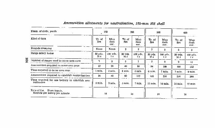
.... 0
""'
Ammunition allotments tor neutralization, 1 05-mm HE shell
Diam. of circle, yards 100 200
II 300
II .
I Kind of data Tr. of Mop Tr. of Map Tr. or Map fire data fire data fire data
cor. cor. cor. -------- -------- -------Rounds sweeping None None 2 2 a 3 ---- -------- --------Range safety factor 50 yds. 100 yds. 50 yds. 100 yds. 50 yds. 100 yds. Y,!c lc Y,!c 1 c Y,!c 1 c -------- -------- --------Number of ranges u~ied to cover area once 1 5 5 7 7 9 -------- -------- --------Ammunition required to cover nrea once 12 20 40 56 84 108 ---- -------- --------Time required to cover area once !min. 2min. 3min. 4min. 6min. 7min. -------- -------- -------Ammunition required to establish neutr&lization 24 40 80 112 168 216 ---- -------- --------Time required for one battery to establish neu-
I tralization 2min. 3min. 5rnin. I 7min. llmin. 14min.
Rate of fire. Short. bursts. Rounds per battery per minute 16 16 16
----
400 -·
Tr.or Map fire data
cor. --------3 3
--------50 yds. 100 yds.
Y,!c 1 c --------
9 11 -------
108 132 --------7min. 9rnin. --------
216 264 --------14m1n. 17rnin.
I 16
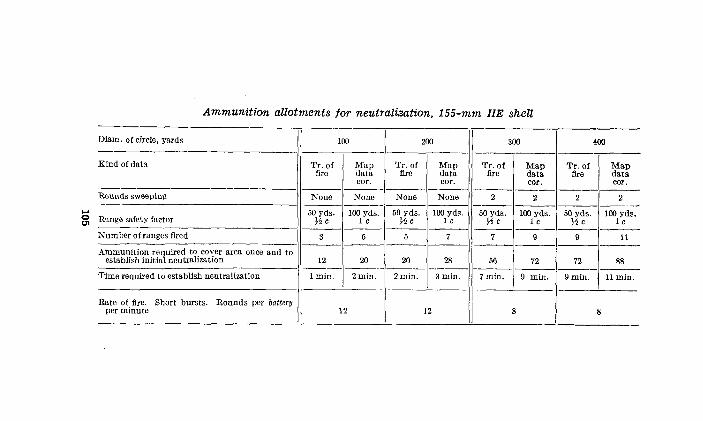
...... 0 t11
Ammunition allotments tor neutralization, 155-mm HE shell
Diam. of circle, yards 100 200 300
---------------Kind of data Tr. of Map Tr. of Map Tr. of Map
fire data fire data fire data cor. cor. cor.
------------------ --------Rounds sweeping None None None None 2 2 ---------------- -------
50 yds. 100 yds . 50 yds. 100 yds. 50 yds. 100 yds. Range safety factor He 1 e He 1 c He 1 e -------· -------- --------- --------Number of ranges fired 3 5 5 7 7 9 ---------------- --------Ammunition required to cover area once and to
establish initial neutralization 12 20 20 28 56 72 ----------- ------ ---- ----Time required to establish neutralization lmin. 2min. 2min. 3min. 7 min. 9 min.
Rate of fire. Short bursts. Rounds per battery
I per minute 12 12 8 - --- -
400 -------
Tr. of Map fire data
cor. --------2 2 --------
50 yds. 100 yds. He 1 c --------9 11 --------72 88
----- ----9min. llmin.
8
-
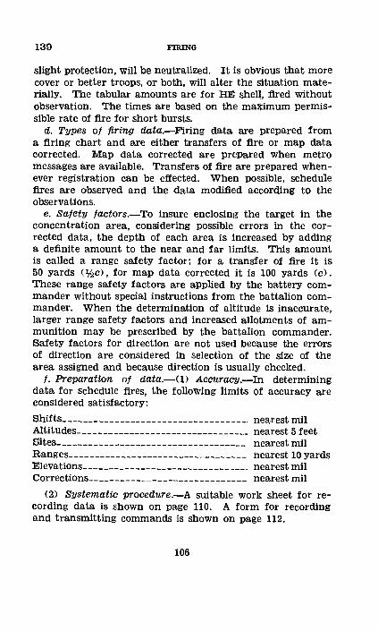
139 FIRING
slight protection, will be neutralized. It is obvious that more cover or better troops, or both, will alter the situation materially. The tabular amounts are for HE shell, fired without observation. The times are based on the maximum permissible rate of fire for short bursts.
d. Types of firing data.-Firing data are prepared from a firing chart and are either transfers of fire or map data corrected. Map <:lata corrected are prePared when metro messages are available. Transfers of fire are prepared whenever registration can be effected. When po$Sible, schedule fires are observed. and the data modified according to the observations.
e. Safety facto1·s.-To insure enclosinl?: the target in the concentration area, considering possible errors in the corrected data, the depth of each area is increased by adding a definite amount. to the near and far limits. This amount is called a range safety factor; for a t:ransf,er of fire it is 50 yards <:!he), for map data corrected it is 100 yards (c). These range safety factors are aPplied by the battery commander without special instructions from the battalion commander. When the determination of altitude is inaccurate, larger range safety factors and increased allotments of ammunition may be prescribed by the battalion commander. Safety factors for direction are not used because the errors of direction are considered in selection of the size of the area assigned and because direction is usually checked.
f. Preparation of data.-(1) Accunu:y.-In determining data for schedule fires, the following limits of accuracy are considered satisfactory:
Shifts ___________ ·---------------------·---· nearest mil Altitudes-----------------------------··--- nearest 5 feet Sites------------------------------------ nearest mil Ranges---------------------------------- nearest 10 yards Elevations-------·---------------------·---· nearest mil Corrections-----··------------------------ nearest mil
(2) Systematic· procedure.-A suitable work sheet for recording data is shown on page 110. A form for recording and transmitting commands is shown on page 112.
106
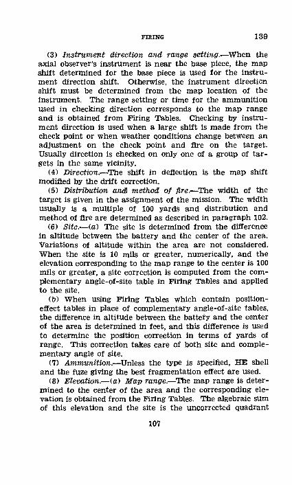
FIRING 139
(3) Instrument direction and range setting.-When the axial observer's instrument is near the base piece, the map shift determined for the base piece is used for the instrument direction shift. Otherwise, the instrument direction shift must be determined from the map location of the instrument. T"ne range setting or time for the ammunition used in checking direction corresponds to the map range and is obtained from Firing Tables. Checking by instrument direction is used when a large shift is made from the check point or when weather conditions change between an adjustment on the check point and fire on the target. Usually direction is checked on only one of a group of targets in the same vicinity.
(4) Direction.-The shift in deflection is the map shift modified bY the drift correction.
(5) Distribution and1 method of fire.-The width of the target is given in the assignment of the mission. The width usually is a multiple of 100 yards and distribution and method of fire are determined as described in paragraph 102.
(6) Site.-(a) The site is determined from the difference in altitude between the battery and the center of the area. Variations of altitude within the area are not considered. When the site is 10 mils or greater, numerically, and the elevation corresponding to the map range to the center is 100 mils or greater, a site correction is computed from the complementary angle-of-site table in Firing Tables and applied to the site.
(b) When using Firing Tables which contain positioneffect tables in place of complementary angle-of-site tables, the difference in altitude between the battery and the center of the area is determined in feet, and this difference is used to determine the position correction in terms of yards of range. This correction takes care of both site and complementary angle of site.
(7) Ammunition.-Uniess the type is specified, HE shell and the fuze giving the best fragmentation effect are used.
(8) Elevation.-(a) Map range.-The map range is determined to the center of the area and the corresponding elevation is obtained from the Firing Tables. The algebraic sum of this elevation and the site is the uncorrected quadrant
107
139 FIRING
elevation. When using position-effect tables ( (6) (b) above), the position correction is applied to the map range before the elevation is determined and no site is added to the elevation.
(b) Limiting elevations.-The elevations for' the far limit and for the near limit of the area are found by applying the elevation change for one half the depth of the, area plus the range safety factor, to the quadrant elevation for the center. This elevation change is determined in multiples of c (taken to the nearest whole miD, the elevation change for 100-yards range change at the map range to the center ot the area.
(c) Elevations jired.-The number of elevations to be fired to distribute the fire over the area is determined by dividing the number of rounds allotted to the mission by the number of rounds necessary to cover the target front at each range or elevation. For ease in firing, ammunition ordinarily is allotted in multiples of the amount necessary to cover the area once. (See tables on pp. 103-105.) Thls basic amount is then used in determining the number of elevations to be fired, thus obtaining a basic set of commands. Thereafter in firing on the area the basic set of commands is used and, by repeating the fire,, any multiple of the basic allotment of ammunition can be fired.
(d) Zone command.-The number of elevation bounds equals % (number of elevations fired minus one). The zone ·command used equals the difference in mils between the limiting elevations divided by the number of bounds. When the tabular allotments of ammunition given in the table on page 103 are used for the 75-mm gun, the number of mils in the zone command will be one c, making the <:amputation unnecessary. For othei· calibers it will be necessary to make the computation as shown above. If the difference between limiting elevations is not a multiple of the number of bounds, either or both elevations may be changed a mil as required.
g. Corrections.--(!) When a number of concentrations are to be fired, the commands, based on uncorrected data, are prepared and sen1; to the battery execut:lve. Corrections K, VE, or map data corrected are computed, based on the last registration or metro message prior to 1iring to concentrations, and these corrections are sent to the executive.
108
FIRING 139
(2) Each observation post should have a list of the targets and the time of firing on each. To identify the targets, the observer must have a description of each, and its measurement right or left of a reference point. He reports on the effect of any fires he can identify; for example, "No. 15, 100 short." Based on these reports, the data are corrected or ineffective ranges eliminated. It is a matter of judgment whether the battery commander uses the observer's report to correct other concentrations which follow.
h. Procedure in preparat.ion ot data, registration permitted, and K-transter used.-U) The battery commander (75-mm guns, M1897) receives an overlay and schedule. Data for the base point and for the concentrations assigned the battery are entered on the work sheet form shown on page 110, and the uncorrected commands are sent to the executive on the command sheet (p. 112).
(2) The battery commander is permitted to register and decides to use K-transfers. The registration gives a deflection correction of right 3 and a K of +20 yards per thousand. The deflection correction is applied by the command BASE
DEFLECTION RIGHT 3; RECORD NEW BASE DEFLECTION. The range corrections in yards are determined for each concentration. These corrections, converted into mils, are transmitted to the executive as follows: "Elevation corrections: No. 1, +6; No. 4, +3; No. 17, +4," etc. The executive strikes out the uncorrected elevations and enters the corrected elevations as shown on the command sheet (p. 112).
(3) H-hour is announced as 6:00 A. M. This is transmitted to the executive who strikes out the times with regard to H-hour and enters the actual times as shown on the command sheet (p. 112).
177568.--39----8 109
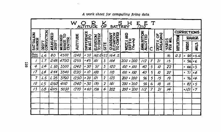
..... ..... 0
~~ .... ~ ~::> lll::Z
~~~7%t I
4 17
7
10
13
a 5
f;:gl ~~ L6
L7
L4
L4
LS
L5 L(J
fil Sgcr: QC :::;> ..... gt:!!F! ~is. :E ~~z ~II) ~ tj
80 4500
1248 4790
L 50 3300
R44 3540
L25 3790
/260 4110
/2115 50JO
A work sheet tar comwting firing data
w 0 R K s H E21
E T ALTITUDE OF BATTERY I /0
11.1 1-:Z~ Q ~~ ~
u_ ~~ lti$. ~~~ ::il::t"" Q';;.-; §~
:c •
~~ 1:;
~:..! trJ t:l~J ~ f-sz ..... ~ Cil odg ~CI'- c 1240 +30 162.0 •2.2 164.2
1255 •45 /81 3 184 200 X 200 112 7
1240 +30 91 J 100 100 X 100 40 5 1220 + /0 109 I 110 100 X 100 40 5 1230 +20 121 2 123 200.200 56 5 1240 +30 139 2 14-1 200.200 56 G
1270 +60 198 4- 2fJ2 200.200 1/2 7
tL,'i:l' CORRECTIONS o= ..J ~ RAAGE. :c.!. ~il b::i ~~ 5 ~ ~ ~~ i Q
16 123 .,. 90 +·5.6
21 15 ~-96 +6
10 22 •66 +3
10 20 • 71 "4 15 19 + 7b +4-18 18 + 82 +5 2/ 14- +10/ +7
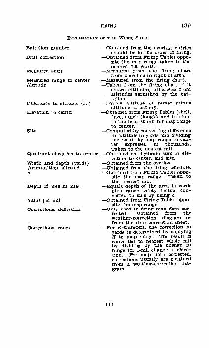
FIRING 139
ExPLANATION OF THE WORK SHEET
Battalion number
Drift correction
Measured shift
Measured range to center Altitude
Difference In altitude (ft.)
Elevation to center
Site
Quadrant elevation to center
Width and depth (yards) Ammunition allotted c
Depth of area In mils
Yards per mil
Corrections, deflection
Corrections, range
-obtained from the overlay; entries should be In the order of firing.
-obtained from Firing Tables opposite the map range taken to the nearest 100 yards.
-Measured from the firing chart from base line to right of area.
-Measured from the firing chart. -Taken from the firing chart If It
shows altitudes; otherwise from altitudes !furnished by the battalion.
-Equals altitude of target minus altitude of battery.
-obtained from Firing Tables (shell, fuze, quick (long)) and is taken to the nearest mil for map range to center.
-Computed by converting difference In altitude to yards and dividing the result by map range to center expressed in thousands. Taken to the nearest miL
--Obtained as algebraic sum of ele-vation to center, and site.
-obtained from the overlay. -obtained from the firing schedule. -obtained from Firing Tables oppo-
site the map range. Taken to the nearest mil.
-Equals depth of the area In yards plus range safety factors converted to mils by using c.
-obtained from Firing· Tables opposite the map range.
-only used In firing map data corrected. Obtained from the weather-correction diagram or from the data correction sheet.
-For K-transfers, the correction in yards is determined by applying K to map range. The result Is converted t01 nearest whole mil by dividing by the change in range for 1-mil change in elevation. For map data corrected, corrections usually are obtained from a weather-correction diagram.
111
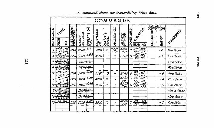
... ... 1>.'1
I ~
"'~ :z ~
:i ~ ~ co I~ .rl5
I 5:40 5=45 .AO -rlj_
4 5=50 5:52 _..,..,. ......-2 . 4 5:56 5:58 /1'1 ../2 4 6:00 6=02
17 /'5 ___,.. 6=05 6:07
- _.A1[} . .A-t3. 1 6:10 6=13
10 .Aft5 ~ G:/6 6:19 .42 .A9 7 6=22 6:29
10 A5 j'f{J
6:35 6:40
13 on call
1-<
~~ :J-0(1-
Iii~ a a 1248
L50
/244
L25
R6fJ
12115
A. command sheet tor transmitting firing data
COMMANDS LATEST
2
~ ~ fl) ~ CORRECTION
a g
~ ~{5 ~ 1-< ~ t= ~~ l!j~
~0 $'t ~ 012 i !o.l (.oJ > ~ ~~= ..,. ~B! ~-oil. § .((,;
8~ ~I:> ~ ~ p,:~ Olll 00 N NEAAFAR
4600 .M:!... 5000 /3 ShMkl 8212S !;7£ _195' rfo~gJ 6/)'1' 7 180 201 f6
3200 l:.M 3500 9 ., 8112d ....95" JUS' +3 5 98 108
!2EP. SIR=-
REP. ~
3400 .fH§_ 350() 8 " BIRd iJB5 .J-15 +1-5 109 1!9
3700 j,_M_ An.n.n u· •!
82125 "LP£i l.JM +4 ¥VVV "'' 8,.r v 120 135
4000 .1?22 4000 15 B212S Lta"2" ..J5C +5 .. 7{)'( 6 137 155
12£Pl :,tt:F-
REP :.4T--
4800 112107 5000 12 .. 8212S Jfn' ~ +7 6(}( 7 /99 220
1--
R --~/ ~
F1re Twice
Ftre Tw1ce
F1re Once.
Finz 7Wicrz
Finz Twice
Fire Once
Fire Once
Fire 3 liine.s
Fire Twtce
Fire Twice
I
... C) tO
~ "'
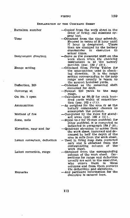
FIRING 139
ExPLANATION OF THE COMMAND SHEET
Battal!on number
Time
Instrument direction
Range setting
Deflection, BD
Converge at
On No.1 open
Ammunition
Method of fire
Zone, mils
Elevation, near and far
Latest correction, deflection
Latest correction, range
Remarks
-copied from the work sheet In the order of firing; call missions appear last.
-Obtained from the time schedule. Entered In terms of Ii hour unt!l H hour is designated. IJ'i.mes then are changed by the battery commander or executive to actual times.
-Same as the measured shift on the work sheet when the checking Instrument is at the battery position (par. 139 f (3)).
-Obtained from Firing Tables for the ammunition used in checking direction. It Is the range setting corresponding to the map range and usually is taken to the nearest hundred yards.
-Obtained as the measured shift corrected for drift.
-Nearest 500 yards to the map range.
-calculated as 30j.R for each hundred yards width of concentration (par. 102 e (1)).
-As assigned for the area or as the battery commander chooses to accompl!sh the mission.
-Computed by the rules for standard areas (par. 102 e (1)).
-Equal to c for 75-mm materiel; for other materiel, It Is computed as indicated In paragraph 139 f (8).
-Quadrant elevation to center from the work sheet, Increased and decreased by half the depth of the area in mils from the work sheet.
-Used In firing map data corrected only and Is obtained from the corresponding column of the• · work sheet.
-Obtained from the corresponding· column of the work sheet. Corrections for range and deflection usually are sent to the executive, who enters them In these columns and from them corrects the deflections and elevations.
-Any pertinent Information for the executive Is entered here.
113
140 FIRING
• 140. STANDING BARRAGEs.-The barrage lines are placed from 200 to 400 yards (at least eight probable errbrs) in front of the line occupied by friendly troops, Each light battery may be assigned two or more barrages on different parts of the front; one as its normal barrage, others as ,emergency barrages. Data for normal and emergency barrages are computed in the same manner.
a. Normal barrage,-<1) Assign.ment .. -The barrage line may be pointed out on the ground, in which case it must be located on the firing chart or adjusted upon accurately. It usually is designated by overlay.
(2) Length.-For a 75-nun battery, the standard length of a normal·barrage is 200 yards; for a 105-mm battery, 300 yards.
(3) Rate of fire.-The rate of fire is a maximum at first, to build up a dense barrier of fire. After several minutes the rate is reduced to one that can be continued without undue heating of the piieces. An example of a suitable rate of fire for a 75-mm battery is six rounds per piece per minute (ROM) for 4 minutes; four ROM for 6 minutes.
(4) When fired.-The normal barrage is fired upon direct signal from the Infantry, usually bY rocket or other visual means. Every possible means of communication must be used to supplement the rocket signal.
(5) Ammunition.-The ammunition used for the barrage is HE shell fuzed to give the most effective fragmentation. Ammunition of a single lot is set aside as a barrage lot (par. 72 c).
(6) Priority.--The normal barrage is the first priority. If the barrage signal is received while firing at another target, fire is shifted immediately to the normal barrage (par. 72 c). . b. Emergency barrages.-The emergency barrages of a battery are standing barrages, any one of which can be fired as ordered instead of its normal barrage. An emergency barrage may be slightly longer than a normal barrage, but for a 75-mm gun battery seldom exceeds 300 yards, and for a 105-mm howitzer battery, 450 yards. Emergency barrages are fired on the authority of the division artillery commander; this authority may be delegated to local artillery commanders.
114
FmiNG 14Q-141
c. Preparation of data.-<1) Direction.-The shift in deflection is the map shift modified by the drift correction.
(2) Distribution and method ot fire.---:,A. close spacing of shots is desired; hence for 75-mm shell the width of a burst is considered as 15 yards; for the 105-mm shell, 20 yards. The width of the barrage is measured perpendicular to the line of fire. If the width is less than four times the effective width of burst given above, fire without sweeping is used; if greater, normal sweeping is used. Distribution and method of fire are determined as described in paragraph 102 except for the value used as width of burst.
(3) Ammunition.-HE shell and the fuze giving the best fragmentation are used.
(4) Range.-The pieces are laid for range by quadrant. When the quadrant elevation for the right piece to the right of the line and for the left piece to the left of the line do not vary by more than one c, range and site are determined to the center of the line and a single quadrant elevation is used by all pieces. When the variation is more than one c, data are computed to lay each piece for range at the center of its section of the line.
d. Corrections.-Usually the fire commands, based on uncorrected data, are furnished the executive on a command sheet. After each registration or after the receipt of each new metro message, corrections are computed and sent to the executive .
• 141. ROLLING BARRAGE.-a. Definition.-A rolling barrage is a system of fire which is placed in front of the infantry in an attack and which advances in short bounds, usually of 100 yards, at a prescribed rate. It consists of a line of fire put down by the light artillery and deepened by concentrations fired by light and medium artillery on sensitive points in advance of the barrage line. The rolling barrage requires a large number of pieces and a large amount of ammunition.
b. Asstgnment.-The basic information for a rolling barrage is given on an overlay shown below on which are shown each line on which fire is to be placed, the time Jimits <with reference to H-hour) between which fire is to be placed on the line, and the rates of fire at different periods of the barrage.
115
141 FIRING
An overlay for a rolling barrage
II) (I) I()
r--,--,----, 6 0 -70
1-+-+---156-60
r--1--i'--1 52 -56
RATE OFFIRE 0-4o , 6 RGH 4-20, 4RGH 20-70, 2RGH
-r--------1297----------+-
c. Length.-The standard front assigned a battery is 100 yards.
d. Rate of fire.-The rate of fire is a maximum at first, and then is reduced so that the number of rounds per hour will not exceed the rate for prolonged fire.
e. Ammunition.-HE shell with the quick fuze is used for the 75-mm gun unless the entire barrage is to be fired at ranges less than 3,000 yards, in which case the delay fuze may be used. When using ammunition with the unit fuze, the fuze is always set at quick.
116
FIRING 141
f. Preparation of data.-<1) General.-The overlay is placed on the firing chart and tacked down or critical lines may be transferred to the firing chart. A critical line is a beginning line, a finish line, or a line where there is a change of direction or a decided change of slope of the ground. If a barrage is deeper than 1,500 yards and there are no critical lines other than the beginning and finish lines, the middle line of the barrage should be taken as a critical line. In determining data for the barrage, it is assumed that range and deflection bounds between critical lines are uniform. Data are determined for each critical line and corrected; data for the intermediate lines are found by interpolation.
(2) Direction.-For each critical line, the map shift for No. 1 is measured and the distribution to place Nos. 2 and 3 on the center of the line and No. 4 on the left of the line is computed. The deflections for each piece are determined as shifts from base deflection.
(3) Method ot fire.-As a rule, cross sweeping is used in order that pieces may be rested. The effective width of burst for 75-mm shell is considered to be 15 yards. The number of rounds and the amount of sweep are determined as in paragraph 102 except for the value used as width of burst.
(4) Range.-Usually, range and site are determined to the center of each critical line and the corresponding quadrant elevation used by all pieces.
(5) Resting pieces.-When the barrage lasts more than an hour, provisions are made to rest the pieces for cleaning and cooling. Sometime during each hour, each piece is rested from 5 to 10 minutes, the rate of fire of the other piece covering the same part of the barrage being doubled to keep the amount of fire constant. The period of rest should coincide with the period of fire on a line, so that changes of rate of fire will be made when other data are being changed. The time of resting and of increasing the rate of fire to compensate for the resting of another piece is indicated on the command sheet for the pieces concerned.
(6) Corrections.-The fire commands, except deflection and quadrant elevation, are entered on section data sheets. After the last registration or after the last metro message,
117
141 FIRING
corrected deflections and quadrant elevations for each critical line are determined and entered on the section data sheets and the sheets are completed by interpolating between critical lines.
g. Conduct at fire.-It is seldom that any adjustment is allowed for a rolling barrage. Surprise is a large factor in an attack, and even a transfer seldom can be made. Since the Infantry follow the barrage at a prescribed distance, it is of primary importance that the barrage line advance at a uniform rate and that the fires of adjacent batteries overlap properly. If the barrage is suspended for any reason, the data used when fire is resumed are those schedUled for the time of resuming fire unless other instructions have been received.
h. Type problem.-The work sheet below is a work sheet for the rolling barrage indicated in the overlay (p. 116) for a 75-mm <M1897) gun battery in staggered positions.
The section data sheet below is an example of a section data sheet for No. 1 piece to fire its part of this barrage.
118
FIRING 141
A work sheet tor a rolling barrage
Line No. No. of piece 3 4 ------------
0 Map dellection __________________ BD R 180 R 170 R 180 R173 Drift correction_--------------------_ L 3 Weather correction _________ ------ ____ R 2 Initial dellection.. ________________ BD R 179 R 169 R 179 R 172 ------------
7 Map dellection __________________ BD R 194 R 186 R 194 R 189 Drift correction ______ ---------------- L 4 Weather correction _________ ---------- R 4 Initial dellection.. ________________ BD R 194 R 186 R 194 R 189 ------------
15 Map dellection __________________ BD R210 R 203 R210 R 206 Drift correction. _____________ -------- L 6 Weather correction ___________________ R 7 Initial deflection ________________ .BD R211 R204 R211 R 207
Line No. No. of piece -------------1------------
0 Map range __________________________ _ Elevation. __ . _____ ..... _. ___ ...•.. __ _ Site _________________________________ _ Weather correction .. ___________ ..... _
3000 84.2
+4.4 -1.6
Same for all pi eces
------------1·------------Quadrant elevation__________________ 87.0
------------1------------7 Map range___________________________ 3700 Elevation____________________________ 116.6 Site__________________________________ +8.1 Weather correction___________________ -3.1 ---------·-----------------Quadrant elevation_----------------- 122.0
15 Map range___________________________ 4500 Elevation____________________________ 162.0 Site__________________________________ +L 5 Weather correction___________________ -7.5
Quadrant elevation.----------------- 156.0
119
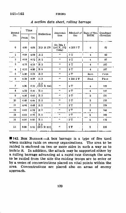
141-142 FIRING
A secticm data sheet, rolling barrage
Time Bound Deflection Ammuni- Method of Rate of fire- Quadrant
No. tion fire RGM elevation From To
---ShMki
0 4:00 4:04 BD R 179 Lot X, FQ 4 RS 3 T 6 87 (long) -------
I 4:04 4:08 H2 .. 3T 4 92 -----2 4:08 4:12 H2 .. 3T 4 97 -------3 4:12 4:16 H2 .. 3T 4 102 -------4 4:16 4:20 H3 .. 3T 4 107
-----5 4:20 4:24 H2 .. 3T nest Piece -------6 4:24 4:28 H.2 .. 4 RS 2T Hest Piece
-----H2
7 4:28 4:32 (BD R 194) .. 2T 4 122 -----
8 4:32 4:36 R2 .. 2T 4 127 --------
9 4:36 4:40 R2 .. 2T 2 131 -----
4:44 I R 2 10 4:40 .. 2T 2 135
11 4:44 4:48 R2 .. 2T 2 139 -----
12 4:48 4:52 R3 .. 2T 2 144 -----
13 4:52 4:56 R2 .. 2T 2 148 -------
14 4:56 5:00 R2 .. 2T 2 !52 -----R2
15 5:00 5:10 (BD R 211) " 2T 2 156
• 142. Box BARRAGE.-A box barrage is a type of fire used when making raids on enemy organizations. The area to be raided is enclosed on two or more sides in such a way as to isolate it. In addition, the attack may be supported either by a rolling barrage advancing at a rapid rate through the area to be raided from the side the raiding troops are to enter or by a series of concentrations placed on vital points within the area. Concentrations are placed also on areas of enemy approach.
120
CHAPTER 4
CONDUCT OF FIRE Paragraphs
SECTION I. GeneraL------------------------------ 143-147 II. Attack of targets---------------------- 148-151
III. Axial--------------------------------- 152-156 IV. Later·al _______________________________ 157-164 V. Combined _____________________________ 165-170
VI. Adjustment with sound-and-flash units __ 171-174 VII. Conduct of fire with air observation _____ 175-186
VIII. Conduct of fire by air observation meth-ods, using ground observers ___________ 187-190
IJ{. Smoke ________________________________ 191-194
J{. Gas---------------------------------- 195-196
SECTION I
GENERAL
• 143. GENERAL.-a. Conduct of fire is the technique of placing artillery fire upon the selected target.
b. When fire on the target can be observed, artillery fire usually consists of adi1JJStment and fire for effect. The object of adjustment is to determine, from the observed positions of the bursts and the target, the firing data to begin fire for effect. The object of fire for effect is to place fire on the target. Effect is desired during adjustment, and adjustment should continue during fire for effect.
c. Artillery fire should be observed if possible, and the terrain at the target studied. When fire on the target cannot be observed, a careful preparation is made, the data are corrected, and a definite area is covered by fire (par. 139).
d. This chapter covers conduct of fire when adjustment is possible. The term battery commander is used to designate the officer conducting fire.
121
143-145 FIRING
e. The following abbreviations are used for commands and sensings:
A, air (sensing) Adj, adjust
AMC, at my command AP, aiming point
B, battery BD, base deflection BL, battery left BR, battery right Ca, compass CF, cease firing Ch, charge Cl, close Cv, converge D, down
Dev, deviation Df, deflection Dr, drum El, elevation
ro, fuze delay FQ, fuze qUick ·
G, graze <sensing) I Dir, instrument direction
Kr, corrector L, left
Mk, mark Op, open PI, plateau Q, c1uadrant R, right
Rd<s>, round <rounds) RGM, rounds per gun per
minute Rn, range RS, rounds sweeping Sh, shell
Shr, shrapnel Si, 1;ite T, target (sensing) T, turns U, up Z, zone
• 144. TYPEs OF FmE.-Artillery fire may be classified as precision fire and bracket fire.
a. The primary object of precision fire is to destroy the target. It consists of a precision adjustment to place the center of impact on the target, and precision fire for effect. Precision methods may be used for an accurate registration.
b. The object of bracket fire is to inclose the target in a suitable bracket and then to cover the bracket thoroughly with fire. The fire consists of a bracket adjustment and zone fire for effect.
c. The type o.f fire used depends upon the nature of the target, the purpose of the fire, and the time available.
a 145. REGISTRATION.-Registration is an adjustment on a selected point to determine data for use in preparation of fire. It may be an adjustment on a point near which the
122
FIRING 145-148
enemy may appear, or on a base point or check point. Registration may be a bracket or a precision adjustment, depending on the time and ammunition available and the degree of accuracy desired.
• 146. SENSING.--a. Sensing is the determination from observation whether a burst is air or graze, above or below the target, right or left, short or over, lost or doubtful. A round must never be sensed positively unless the observer is sure the sensing is correct.
b. Sensings are usually made on shots in line with the target. Under some conditions, valuable information is obtained from drifting smoke or from shadows of bursts not in line with the target. When the terrain near the target is known, positive sensings for deflection and range may often be obtained from shots not in line with the, target (terrain sensings) .
• 147. ELEMENTS TO BE ADJUSTED.-The following elements must be adjusted:
a. Direction, to determine a deflection which will cause the line of fire to pass through the target.
b. Distribution, to determine a deflection difference which will cause the sheaf to cover the desired front.
c. Height of burst, in case of time fire, to obtain a corrector or time setting which will give the desired mean height of burst.
d. Range, to determine the elevation or range setting which will produce maximum effect on the target, Qther elements being correct.
SECTION II
ATTACK OF TARGETS
:• 148. CLASSES OF TARGETS.-The method of attacking targets depends on their mobility and physical characteristics. As to mobility, targets are considered as rapidly moving, slowlY moving, or fixed. As to physical characteristics, they are considered as material targets, personnel targets, and materiel manned by personnel.
123
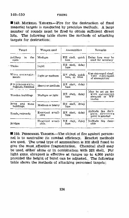
149-150 FIRING
•149. MATERIAL T'ARGETs.-Fire for the destruction of fixed material targets is conducted by precision methods. A large number of rounds must be fired to obtain sufficient direct hits. The following table shows the methods of attacking targets for destruetion:
I
Target Weapon used Ammunition Remarks
Artillery in the Medium HE shell. quick Delay fuze may be open fuze used for accuracy·
·-Tanks Light HE shell, delay
fuze
Wire entangle- HE shell, quick Use converged sheaf. ments Lh~ht or medium
fuze~ or time Very extravagant of ammunition
Emplacements, He.avy or medium HE shell, delay dugouts, trenches fuze
May be set on fire HE shell, delay Wooden buildings Medium or light with percUSS lOll
fuze shrapnel or WP smoke
Brick and stone Medium or heavy HE shell, delay buildings. fuze
Hila viest avail- HE shell, delay Enfilade fire desir-Roads, railroads able; sensitive able fuze point is selected -------~
Heaviest avail~ BE shell, delay )enfilade ·fire desir-Bridges able. fuze able
• 150. PERSONNEL TARGETS.-The object of fire against personnel is to neutrali:re its combat efficiency. Bracket methods are used. The usual type of ammunition is HE shell fuzed to give the most. effective fragmentation. Chemical shell may be used, either alone or in combination with HE shell. For light guns, shrapnel is effective at ranges up to 4,000 yards provided the height of burst can be adjusted., The following table shows the methods of attacking personnel targets:
124
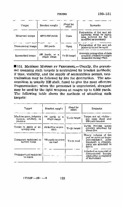
FIRING 150-151
Target Bracket sought Sheaf for Remarks effect
Preparation of fire and ad-Mounted troops 400 to 800 yards Open justment must be rapid;
area covered by fire is modified as necessary
Dismounted troops 200 yards Open Preparation of fire and ad-justment must be rapid
Accurate preparation of data 100 yards, or a Intrenched troops single range To fit target possible; ineffective ranges discarded during effect
8151. MATERIEL MANNED BY PERSONNEL.-Usually, the personnel manning such targets is neutralized by bracket methods; if time, visibility, and the supply of ammunition permit, neutralization may be followed by fire for destruction. The ammunition is usu~tllY HE shell, fuzed to give the most effective fragmentation; when the personnel is unprotected, shrapnel may be used by the light weapons at ranges up to 4,000 yards. The following table shows the methods of attacking such targets:
Target Bracket sought Sheaf for Remarks effect
Machine guns, infantry 100 yards or a To fit target Target not all visible-cannon, artillery, in single range use open sheaf and position 20o-yard bracket
'ranks in defile or as- As narrow as pos- Tanks moving across To fit target country attacked by semblyarea sible direct fire
Heavy volume of fire put on point as trans-
Transport restricted to 100 yards on point To fit road port reaches it. After narrow route on road transport is stopped,
parts are attacked in detail
Attacked as mounted or Transport not restricted dismounted troops, .. ------- --------- -------------- depending on rapidity to roads of movement
177568"-39--9 125
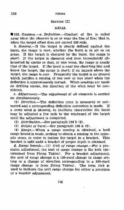
152 FIRING
SECTION III
'AXIAL
• 152. GENERAL.-a.. Definition.-Conduct of fire is called axial when the observer is on or near the line of fire; that is, when the target o!Tset does not exceed 100 milS.
b. Sensing.-If the taxget is clearly defined against the burst, the range :is over, whether the burst is in air or on graze. If the target is obscured by the burst, the range is short. If the taxget is obscured and then immediately silhouetted by smoke or dust, or vice versa, the range is nearly that of the target. If the burst is near the observing line and below the target, the range is short; if on impact above the taxget, the range is over. Frequently the target is on ground which justifies a sensing of los·t over or lost shart when the deflection is approximately correct. When sensings are made on drifting smoke, the direction of the wind must be con-sidered. ,
c. Adjustment.--The adjustment of all elements is carried on simultaneously.
(1) Direction.--The deflection error is measured or estimated and a corresponding deflection coiTection is made. If a cross wind is blowing, to facilitate observation the burst may be adjusted a few mils to the windward of the target until the adjustment is completed.
(2) Distribution.--See paragraph 154 b· (2). (3) Height of 'burst.--See paragraph 155 b (2). (4) Range.-When a range sensing is obtained, a bold
range bound is made, seeking to obtain a sensing in the opposite sense, in order to inclose the taxget in a bracket. This bracket is split until a bracket of proper depth is obtained.
d. Range bounds.-<1) Unit of range change.-For a precision adjustment, the unit of range change is the fork (determined from F'iring Tables). For a bracket adjustment, the unit of range change is a 100-yard ehange in range setting or a change of elevation corresponding to a 100-yard range change (c from Firing Tables) . The term fork is used to indicate the unit range change for either a precision or a bracket adjustment.
126
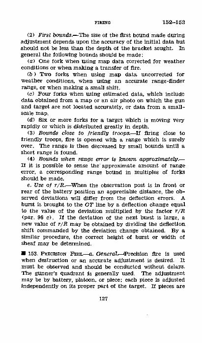
FIRING 152-153
(2) First bounds.-The size of the first bound made during adjustment depends upon the accuracy of the initial data but should not be less than the depth of the bracket sought. In general the following bounds should be made:
(a) One fork when using map data corrected for weather conditions or when making a transfer of fire.
(b ) Two forks when using map data uncorrected for weather conditions, when using an accurate range-finder range, or when making a small shift.
<c) Four forks when using estimated data, which include data obtained from a map or an air photo on which the gun and target are not located accurately, or data from a smallscale map.
(d) Six or more forks for a target which is moving very rapidly or which is distributed greatly in depth.
(3) Bounds close to friendly troopSI.-If firing close to friendly troops, fire is opened with a range which is surely over. The range is then decreased by small bounds until a short range is found.
(4) Bounds when range error is k7UY11Yn approximately.If it is possible to sense the' approximate amount of range error, a corresponding range bound in multiples of forks should be made.
e. Use of rjR.-When the observation post is in front or rear of the battery position an appreciable distance, the observed deviations will differ from the deflection errors. A burst is brought to the OT line by a deflection change equal to the value of the deviation multiplied by the factor r;R (par. 96 c). If the deviation of the next burst is large, a new value of rjR may be obtained by dividing the deflection shift commanded by the deviation change obtained. By a similar procedure, the correct height of burst or width of sheaf may be determined.
• 153. PRECISION FmE.--a. General.......-4Precision fire is used when destruction or an accurate adjustment is desired. It must be observed and should be conducted without delays. The gunner's quadrant ~s generally used. .The adjustment may be by battery, platoon, or piece; each piece is adjusted independently on its proper part of the target. If pieces are
127
153 FIRING
adjusted successively, the adjusted elevation of the first piece is used as the initial elevation of the others. In accurately calibrated batteries, the adjusted elevation of the ·first piece may be used as the trial elevation of the others.
b. Addustment.--The object of precision adjustment is to obtain a trial elevation for each piece. A trial elevation is the center of a one-fork or less elevation bracket, or an elevation giving a target hit. One sensing at each limit of the bracket is sufficient to determine a trial elevation. The method of fire during adjustment is, for a single piece, one round; for a platoon or battery, salvos fired at intervals which will permit recording the sense of each round. The fork <taken to the nearest miD uorresponding to the initial quadrant elevation ls used. If a bracket ls not obtained after a total elevation change of eight forks, a new value of the fork, corresponding to the last quadrant elevation, is used. The first round from a cold piece is often erratic and should be disregarded if it is a limit of the final bracket.
c. Fire tor effecrt.-(1) Fire for effect is started at the trial elevation. Groups of six sensings are desired for each piece. A shot fired during adjustment at an elevation later used in the first effect group may be considered as part of that that group.
(2) If the trial elevation is determined by a target hit, five shots are fired immediately in one series.
(3) If the trial elevation is the center of a one-fork bracket, the first group of six shots is fired in half groups of three. If the shots of the :first half-group are all in the same sense, the elevation is changed one-half fork, o:r to the limit of the bracket, in the proper direction, and enough shots are fired to complete three sensings at this elevation. The group is considered to have been fired at the meam of the two elevations used.
(4) An adjusted elevation is computed after each group and the next group is fired at this elevation. If the first group of fire for effect gives an equal number of overs and shorts, the adjusted elevation is the one at which the group was fired; otherwise, the adjusted elevation is determined as follows: Find the difference between t'he number of overs and shorts, neglecting target hits. A'ldl this number ot
128

FIRING 153-154
twelfths of a fork to the elevation used, if the number of shorts exceeds the number of overs; subtract if the overs predominate. For this calculation, the fork taken to the nearest mil corresponds to the elevation at which the group was fired. Further fire for effect is in groups of six rounds, additional rounds being fired, if necessary, to obtain six sensings. After the second group, the adjusted elevation is determined by making one half of the change indicated above; after the third group, one third; and after the fourth and following groups, one fourth. If there are five observations in one sense in the first group for effect and six in this same sense in the second, adjustment is begun anew.
d. Registration.-For registration, the first or second group of fire for effect should be included, depending upon the accuracy desired .
• 154. PERCUSSION BRACKET.-a. General.-0) The object of percussion bracket adjustment is to inclose the target in a bracket of appropriate depth, or to find a range which will give both shorts and overs, and to adjust the deflection and distribution. Targets sUitable for bracket fire are usually transient, which makes speed essential; registration on selected points expedites opening fire.
(2) Adjustment may be with one piece until a 400-yard range bracket is split, or a 200-yard range bound is made; thereafter battery salvos are used to complete the adjustment. When initial data are accurate, the target is fleeting, or observation is difficult, fire should be started with battery salvos.
(3) When fire is opened with one piece, the initial sheaf is computed to fit the visible part of the target. When adjustment is started with the battery, an open sheaf is used unless accurate map data are employed or a small shift is made. This increases the chance of a range sensing from the first salvo.
(4) A salvo or volley is said to be bracketing when the number of rounds sensed short is equal to the number sensed over; it is said to be mixed when sensings of both over and short are obtained, but more are in one sense than in the other.
129
154 FIRING
b. Adiustment.·-<1) Direction.-The deflection error of the piece most nearly correct is measured, and an appropriate deflection correct:lon is made.
(2) Distribution.-If the first deflection is fP'eatly in error, the deflection shift may not be correct. In this case, to increase the chance of obtaining a range sensing, fire is continued with an open sheaf until the deflection is approximately correct, when the sheaf is adjusted to fit the target. A change of deflection difference, to the nearest mil, is made with reference to the piece most nearly correct for deflection. When a piece is materially out of its place in the sheaf, it is corrected by an :individual deflection shift. If only a pait of the target is visible, the sheaf is adjusted to the visible part of the target. On a very narrow target, adjustment is made with a converged sheaf. If the entire target is visible, the sheaf is adjusted so as to pass to fire for effect without change of distribution.
(3) Range.-A 200-yard range bracket usually is considered sufficient for adjustment. When the target is fixed, of little depth, and clearly visible, a 100-:vard bracket should be sought. When the target is movim~ rapidly, has great depth, or is poorly defined, a 400-yard or greater bracket may be necessary. One sensing is sufficient basis for a range change during adjustment. Fire for effect is started after one sensim~ at each limit of the bracket or when a bracketing or mixed salvo or a target Qit is obtained. Verification of the bracket is sought dUii:ng fire for effect.
c. Fire for etfect.-<1> A definite zone is covered; the density of fire depends upon the nature of the target and the amount of ammunition available.
(2) The deflection is changed as necessary so that the mean line of fire will pass through the center of the ta~get.
(3) If all elements of the target are not visible or if the target is not fixed, an open sheaf should be used. If the target cannot be covered with an open sheaf, it is attacked by sweeping fire or by successive shifts (par. 102).
(4) The bracket determined during adjustment is covered rapidly, using 100-yard bounds, and then the intermediate ranges are included; ranges clearly ineffective are discarded. If a sirigle sensing has determined one limit of the bracket
130
FIRING 154-155
and no rounds are observed in the sense of this limit during early fire for effect, a zone extending 100 yards outside this limit should be included in later fire.
(5) If the target is moving in the direction of range, fire for effect is started at the limit toward which movement is taking place. If a bracket is obtained with one sensing at one limit and more than one at the other, fire for effect is started at the limit at which only one sensing has been obtained, to get prompt verification. In general, when beginning fire for effect, delays incident to changing range settings should be avoided.
(6) If, during adjustment, a bracketing Qr mixed salvo or a target hit is obtained, this range is considered the center of the desired bracket and fire for effect is started at this range. If a 200-yard bracket is appropriate, the remainder of the zone is covered promptly; if a 100-yard bracket, fire is con• tinued at the bracketing or mixed range unless a decided preponderance of the effect is sensed either over or short, in which case a range 50 yards in the appropriate direction is included.
• 155. 'I'IME BRACKET.-a. General.-0) The principles of percussion bracket adjustment and fire for effect apply to time-bracket fire. In addition to adjusting the other elements, a mean height of burst is sought which will give the most effective distribution of shrapnel balls or shell fragments at the target.
(2) An air burst silhouetting the target may be sensed over; one obscuring the target, short. When the effect of an air burst is over, the range is over; when short, a sensing of short should be taken with caution unless the burst is low or the effect is very short.
(3) Bursts are classified as follows: <a) Graze, a burst on impact with the ground. (b) Graze above, a graze more than one probable error
above the base of the target (in determining proportions, considered doubtfUl for height of burst).
(c) Graze below, a graze more than one probable error below the base of the target.
(d) Air, an air burst above the base of the target.
131
155 FIRING
(e) Below, an air burst below the base of the target (in determining proportions, considered a graze).
(4) An equal number of airs and grR!~es indicates a zero height of burst. Three airs and one gra-ze indicate a mean height of burst of one probable error above the base of the target. Three grazes and one air indicate a mean height of burst of one probable error in the ground.
b. Ad1ustment.--<l> Deflection, distribution, and range.The adjustment of deflection, distribution, and range is the same as in percussion bracket.
(2) Height of burst.-<a> A low height of burst, giving from one third to one half of the bursts on graze, is desirable for adjustment. Height of burst usually is regulated by changes in corrector or time; in some cases by changes in site. Bold changes are made until a corrector bracket is obtained. This bracket is split until a corrector bracket of either two or three points is obtained. A corrector change of less than two points is never made;
(b) When the adjustment is started with salvos, usually the best corrector change after the first salvo, when all rounds are in the same sense (all air or all graze), or are lost, is 10. When the grazes and airs are equal in number, no corrector change is given; when they are unequally divided and the same division is repeated in the next salvo fired without a corrector change, a corrector change of 5 mils is indicated. No corrector change is indicated if all rounds fired result in grazes above.
(c) To avoid running off the corrector scale, the first correction of a large error in height of burst should be made by a site change. If the first salvo is more than 15 mils above or below the target, the site is changed a multiple of 5 mils nearest to the measured or estimated error. After a site change, previous range sensings are not used to establish the limit of a bracket.
(d) When the adjustment is started with a single piece, the first corrector change usually is 10. The corrector is bracketed in the same manner as when using salvos. A corrector bracket established by one piece only does not give accurate information of the position of the height-of-burst center. Hence, after a height-of-burst bracket has been established
132
155-156
with one piece and the battery has been brought in, the usual corrector change is five 1f a corrector change is indicated.
(e) After the zero corrector for the day <the corrector setting which gives a zero height of burst under the existing atmospheric conditions) has been found, an initial corrector change of five usually will be sufficient if the site has been accurately determined.
c. Fire tor effect.-(!) The principles of percussion bracket fire for effect apply in general. The height of burst with shrapnel is obtained by drawing the burst back along the trajectory, from a zero height of burst, by raising the corrector; for shell, it is obtained by raising the bursts vertically, from a zero height of burst, by means of the site or quadrant elevation.
(2) With the 75-mm gun firing shrapnel at a normal height of burst, from one fourth to one eighth of the bursts will be grazes. If the last corrector setting for adjustment gave an equal number of air and graze bursts, the corrector should be raised two or three points when going to effect; if three fourths were graze bursts, the corrector should be raised five; if three fourths were air bursts, no corrector change should be made.
(3) When firing shell with the 75-mm gun, an effective height of burst is about 15 yards, indicated at midranges by one fourth to one eighth grazes. The height of burst for effect, when the height of burst for adjustment was zero, is obtained by raising the site (or quadrant elevation) 15/R mils. This amount is modified as appropriate when the final height of burst for adjustment was other than zero.
(4) When firing on slopes, appropriate changes of the corrector are made to correspond with the degree of the slope . . • 156. DIRECT LAYING.-a. General.-In direct laying, the line of sighting of each piece is directed upon the point indicated as the target, thus laying the piece for direction and site. With certain types of materiel, direction only is obtained bY direct laying; site is obtained by leveling a bubble. Conduct of fire is the same as with indirect laying except for the adjustment of the deflection and distribution. For certain types of targets, the battery may be handled as a unit; for
133
156 FIRING
others, such as tanks and armored cars, attacking on a broad front, each piece may be handled individually by its chief of section or by an officer, as directed by thE~ executive.
b. Moving targets other tham tanks ami thi like.-Moving targets usually remain visible a very short time, and extreme . rapidity and accuracy of fire are necessary in order to obtain effect.
(1) Method of flre.-The method of fire is by volley. (2) Deflection.--The initial defiection and subsequent de
flection corrections to compensate for wind, drift, and movement of the target are announced by the battery commander. The first shots should be ahead of the target rather than behind it. A rough rule for the initial defiection lead for movement of the target normal to the line of fire is 5 mils for a walk, 10 mils for a trot, and 15 mils for a gallop.
(3) Distributiolll .. -The battery commander trains his chiefs of section to indicate to their respective gunners the particular part of the target on which to lay.
(4) Height of burst.-If shrapnel is used, the height of burst must be adjusted promptly, since the effectiveness of fire decreases rapidly as the burst varies from normal.
(5) Range.-Depending upon the direction of movement of the target, boldl range bounds, 400 to 1300 yards, are made in order to obtain a bracket promptly. In order to bring dense fire on the target, fire for effect is usually by volleys of two rounds.
c. Antitank jire.-Fire against tanks and other armored combat vehicles ordinarily is by individual light piece, with direct laying, conducted by the chief of section.
(1) PreparatiO'Ii'-8.-Ranges to the critical points in the probable area of approach are determined, notation being made"of defiladed areas. The piece is placed on level ground and arrangements made to facilitate rapid shifting of the trail. The piece is laid at the center of the sector, with traverse centered and defiection zero (plateau 0 drum 100). The ammunition is HE shell with the delay fuze.
(2) Conduct of jire.-The conduct of fire for the various types of materiel is described in the pertinent manual in the FM 6-series for the Service of the Piece. The initial
134

FIRING 156-157
deflection for a target <which is modified as conditions warrant> is that which affords the proper lead for movement of the target. The lateral component of target movement in mils during a 2-second interval gives the proper deflection lead for a range of 1,000 yards. Counting "four" in quicktime cadence approximates a 2-second interval. This is modified as the range is greater or less than 1,000 yards. Bold range changes are made until the range is effective or just short of the target. Fire is maintained at this range until the target has passed through the fire, when an appropriate range change is made. The range is not set at less than 400 yards.
SECTION IV
LATERAL
• 157. GENERAL.-a. Definition.-Conduct of fire is termed lateral when the target offset T exceeds 100 mils. Deflection errors cannot be measured accurately as in axial conduct of fire. Procedure during adjustment consists, in general, of two operations: bringing the burst into line with the target as viewed by the observer; and keeping the bursts in this position during the changes incident to adjustment.
b. Adjustment.-(!) When T is small UOO to 300 mils), range adjustment is more difficult than deflection adjustment; hence the procedure is designed to facilitate range adjustment. When T is large (more than 300 mils), deflection adjustment is more difficult than range adjustment; hence the procedure is designed to facilitate deflection adjustment.
(2) When T is small, the target is bracketed for range; when T is large, the target is bracketed for deflection. These brackets (range or deflection) are established by shots which are on the OT line or which are computed thereto. The bracket is split until a point is reached where fire for effect may be started.
c. Terms used (fig. 16) .-(1) The observing line OT is the line joining the observer and the target.
135
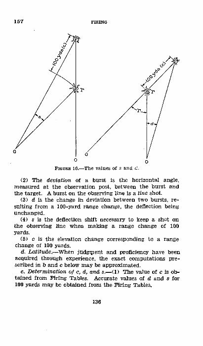
157 FIRING
/ G
G
0 0 FIGURE 16.-The values of s and c2.·
(2) The deviation of a burst is the horizontal angle, measured at the observation post, between the burst and the target. A burst on the observing line is a line shot.
(3) d is the change in deviation between two bursts, resulting from a 100-yard range change, the deflection being unchanged.
(4) s is the deflection shift necessary to keep a shot on the observing line when making a range change of 100 yards.
(5) c is the elevation change corresponding to a range change of 100 yards.
d. La:titude.-When judg~pent and proficiency have been acquired through experience, the exact computations prescribed in b and c below may be approximated.
e. Determinatknt ot c, d, and s.-<1) The value of cis obtained from Firing Tables. Accurate values of d and s fDr 100 yards may be obtained from the Firing Tables.
136
FIRING 157
(2) When T is less than 600 mils, approximate values of d and s may be calculated by the following formulas:
1 1 TOT lOT
a=r s=If (3) For values of T greater than 600 mils and when con
ditions of time and accuracy warrant, the values of s and d should be taken from the Firing Tables.
\4) Accurate values of s and d may be determined also by the following formulas:
100 tangent T s R
d 100 sin T r
For example: T=400 mils. R=4. r=3.
s= 100 _.x .4 = 10 mils. d _100 X .4-13 "1 .., --3--- m1 s.
A table of natural functions is given in the Firing Tables. (5) When the range is to be changed by multiples of the
fork instead of by multiples of 100 yards or c, the value of s is modified to conform to the size of the fork by multiplying s by-
Fork in mils or Fork in yards c 100 yards
Hereafter, s will represent the deflection change for a range bound of either 100 yards or one fork, whichever is indicated by the context.
/. Sensing.-0) Deflection is sensed as short if the burst appears on the observer's side of the gun-target GT line; as over if the burst appears on the far side of the GT line. It is considered correct if a target hit is obtained, if a 2-mil deflection bracket is split, or if sensings of deflection over and deflection short are obtained at the same deflection setting.
(2) Shrapnel.-The effect c;>f air bursts often will indicate the line of fire. When possible, deviation should be sensed from the pattern instead of the burst. When only the burst is sensed, the fact that a change of five points in the corrector changes the burst range about 100 yards (changing the devia-
137
157-159 FIRING
tion one d) must be considered when bringing a burst to the observing line by :a range or deflection change,
(3) SenSing by rule.-When the deflection error is not greater than Y2 s, a burst whose deviation is on the side of the observing line toward the guns may be sensed short for range; a burst whose deviation is on the side of the observing line away from the guns may be sensed over for range. Bursts should be sensed llY this rule only when they cannot be sensed on the target or on terrain.
B 158. SMALL TARGET OFFSET, GENERAL.-When T is small <100 to 300 mils), the procedure is the same as that used in axial conduct of fi.re except that when range bounds are made, small deflection changes are made to keep the bursts on or near the observing line. The size of the range bound is the same as in axial conduct of fire.
B 159. SMALL TARGET OFFSET, PRECISION.-a. General.-Adjustment is by single piece. The piece is laid for elevation with the gunner's quadrant. The method of fire for adjustment is one round. During adjustment, a burst is sensed for deviation and range. Examples: Line over; 8 right, doubtful; 7 lett, short; target. During fire for effect, a burst is sensed for deflection also. Examples: 2 left, short, deflection doubtful; 3 right, over, deflection doubtful; line, over, deflection over.
b. Adiustment.·-<1> To ge.t on the line.-If a burst cannot be sensed for range because of its deviation, the next burst is brought to the observing line by a deflection change of r jR times the deviation. If the next burst is far from the observing line, a new value of r jR may be obtained by dividing the commanded deflection shlft by the deviation change observed (par. 152 e). The use of such a factor gives exact results only on level ground and when there is no dispersion. ·when the ground is i.rregula.r or when r does not differ g:rea.tly from R, the factor may be dispensed With. The deflection change is the observed (leviation, modified as necessary by estimation, to meet the special conditions. Facility in this respect is acquired by experience.
138
FIRING 159
(2) To stay on the line.-When the first range sensing has been obtained, a range bound of the proper number of forks is made. The corresponding deflection change to keep the burst on the line is the shift to put the last shot on the line plus a shift of the number of s-bounds equal to the number of fork bounds. If the next burst is not on the line and not sensed for range, a shift is made to put it on the line; if the burst is sensed for range, the shift necessary to put the burst on the line is applied to the shift made to! correspond to the next range change. A corrected value of s may be computed by dividing the total shift from line shot to line shot by the number of s-bounds. This value of s may be used during the remainder of the adjustment. The value of s is changed only when it is determined to be in error by two mils or more.
(3) Range.-The adjustment for range continues as in axial conduct of fire. A deflection shift of one s is made for each fork; range bound.
c. Fire for e;Uect.-Fire for effect is started at the trial elevation (par. 153 b) and at the deflection to put the bursts on the observing line. Since the deflection error should not be greater than % s, range may be sensed by rule. After a positive deflection sensing, the deflection is changed % s or two mils, whichever is greater, until a deflection bracket is obtained. This bracket is split until the deflection is correct. Rounds are fired in half -groups of three until the deflection, is correct, after which rounds are fired in groups of six.
d. Type prob~ecision, small T; plotted data.-75-mm gun, M1897; target, a check point; mission, to register with shell Mk. I, fuze quick Oong) ; battery commander on the left of the gun-target line.
T=260 mils; r=3.4; R=4.2; F=5; c=6. s for 100 yards= (lj10X260) /4.2=6 mils. s for one fork=6X5/6=5 mils. r;R=3.4/4.2=.8.
139
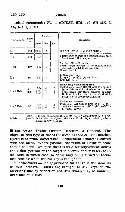
159-160 FIRING
Initial commands: NO. 1 ADJUST, BDL 110, SH MK. 1-FQ, NO. 1, 1 RD.
Sensing
Commands Eleva- Rematks tion Dev. Rn. Def. ----
Q 140 30 H ? 30xr/R=30x .8=L 24 to get on line. -----
L 24 140 Line - 2-fork range change to he made; hence shift 2s=2x5=R 10to sta1{online.
----3 x .8=R 2 to get on li'ne.
R 10 150 3L + 1-fork range change to he made; shift=L ls=L 5to sta1{online.
R2+L5=L3.
hence
12 I~ --
L 2 to get on line. L3 145 + L ~s=L 2 (or 3) to sta1{on line.
L2+L2=L4.
Range may he sensed l;ly rule. 2L + ? Deflection is over (right) and is changed
L4,3Rds. 143 Line + + ~28 too htain a deflection bracket. Range
(142) Line + + over; hence elevation changed to short limit of bracket, and 2 rounds fired to complete the group of 6 sensings. --
Deflection is correct. Line + + Fork is 5. All roundS fired at. 141.5 (141).
L3, 2Rds. 140 Line - - Adjusted elevation=141.5 (141)-(2/12 x 5) =140.7 (140.2).
140.7 is the command if a more preoise adjustment is desired. 6Rds. (140.2) Otherwise the adjusted data are: BDL 134, adjusted quadrant
elevation 140.7 (140.2) .
• 160. SMALL TARGET OFFSET, BRACKET . ....-a. General.-The object of this typE! of fire is the same as that of axial bracket. Speed is of prime importance. Adjustment usually is started with one piece. 'IVhere possible, the rang·e or elevation scale should be used. An open sheaf is used for adjustment unless the visible portion of the target is narrow and T is less than 200 mils, in which case the sheaf may be narrowed to facilitate sensing when the battery is brought in.
b. Adiustment.--The adjustment for range is the same as in axial bracket. Bursts are brought to and kept on the observing line by deflection changes, whlch may be made in multiples of 5 mils.
140

FIRING 160-161
c. Sensing.-Deflection is not sensed until the battery is brought in. Thereafter, the deflection of each salvo or volley, as a whole, is sensed.
d. Fire tor ejJect.-Fire for effect is started as in axial bracket adjustment (par. 154). The deflection is improved whenever positive deflection sensings can be made. Inasmuch as shots at the midrange of the bracket usually will give the best deflection sensings, fire for effect should be begun at that range. An open sheaf usually is used in fire for effect. However, when the entire target is visible and its width is considerably less than the width of an open sheaf, the sheaf may be converged to fit the target on information obtained from positive deflection sensings.
e. Type problem-percussion bracket, small T; estimated data.-75-mm battery, M1897; target, Infantry in vicinity of a tree; battery commander on the left of the gun-target line.
T=250; r=3; R=4; rjR=%; s=6. Initial commands: BDL 280, CV AT 4,000, ON NO. 1 OP 8, SI -5, SH MK. I, FQ <LONG), NO. 2, 1 RD.
Sensing
Commands Range Remarks
Dev. Range De f. ----
4000 45 L ? 45 X %;=33 -------
R 35 4000 6R ? 6 X %;=5 ----
L5 4000 Line - 4 X 6=24 -------
R 25 4400 7L + 7 x %;=R 5 to get on line 2 x 6= L 12 to stay on line
----L5,BR 4200 ?--- -
----R 10, B 1 Rd 4300 Fire for effect started at center of
bracket to verify deflection ----
4400 Battery commander improves de-4200 flection as positive sensings are 4250 obtained 4350
• 161. LARGE TARGE,T 0FFm:T, GENERAL.-When T is large (greater than 300 m11s), shots are brought to the observing line by range changes. The deflection is changed only when
177568'-39-10 141
161-162 FIRING
a deflection sensing is obtained, the size of the initial shift depending on the accuracy of the initial data. In general, with estimated data the initial deflection shift should be 4 s or more, depending on the proficiency of the observer in estimating data. When data are obtained by plotting, the initial shift should ordinarily be 2 s. With map data corrected or transfers, the ini1;ial shift should be 1 s. Since the above shifts are determilDed before the firing of a round, the size of the initial shi:rt may be modified, based on the initial sensing, by making either a larger or smaller shift than had been predetermined. The initial shift should be % s, s, 2 s, 4 s, 8 s, and so on for ease in splitting the deflection bracket .
• 162. LARGE TARGET OFFSET, PRECISION.--a,. General.-Adjustment is by single piece. The piece lls laid for elevation with the gunner's quadrant. The method of fire for adjustment is one round. During adjustment, a, burst is sensed for deviation and de1iection but need not be sensed for range. Examples: 2 left, deflection slwrt; 15 right, deiflection doubtful; line, deflecticm over. During fire for effect, a burst is sensed for range also. Examples: 2 left, short, deflection short; 5 right, over, deflecticm doubtful; line, short, deflecticm short.
b. Adiustment.--(1) To get on the line.-<a> If a burst cannot be sensed for deflection because of its deviation, the next burst is brought to the observing Jline by an elevation change equal to the deviation multiplied by c/d.
(b) If the next burst is far from the observing line, a new value of c;d may be obtained by dividi.ng the commanded elevation change by the observed deviation change. The use of·such a factor ~:ives exact results only on level ground and when there is no dispersion. When the ground is irregular or difficult, the factor may be dispensed with and the line bracketed by estimated range changes; or the factor may be applied, With an estimated correction to meet the special conditions. Facility in this respect is acquired by experience.
(c) During adjustment, each burst is eomputed to the line as indicated above, but if a deflection sensing was obtained, an additional shot is not fired.
142
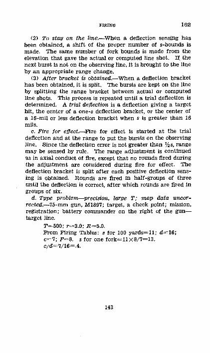
FIRING 162
(2) To stay on the line.-When a deflection sensing has been obtained, a shift of the proper number of s-bounds is made. The same number of fork bounds is made from the elevation that gave the actual or computed line shot. If. the next burst is not on the observing line, it is brought to the line by an appropriate range change.
(3) Alter bracket iS obtained.-When a deflection bracket has been obtained, it is split. The bursts are kept on the line by splitting the range bracket between actual or computed llne shots. This process is repeated until a trial deflection is determined. A trial deflection is a deflection giving a target hit, the center of a one-s deflection bracket, or the center of a 16-mil or less deflection bracket when s is greater than 16 mils.
c. Fire for effect.-Fire for effect is started at the trial deflection and at the range to put the bursts on the observing line. Since the deflection error is not greater than Y:!s, range may be sensed by rule. The range adjustment is continued !ts in axial conduct of fire, except that no rounds fired during the adjustment are considered during fire for effect. The deflection bracket is spilt after each positive deflection sensing is obtained. Rounds are fired in half-groups of three until the deflection is correct, after which rounds are fired in groups of six.
d. Type problem-precision, large T; map data uncorrected.-75-mm gun, M1897; target, a check point; mission, registration; battery commander on the right of the guntarget line.
T=500; r=3.0; R=5.0. From Firing Tables: s for 100 yards=ll; cZ=16; c=7; F=8. s for one fork=l1X8/7=13. c;d=7/16=.4.
143
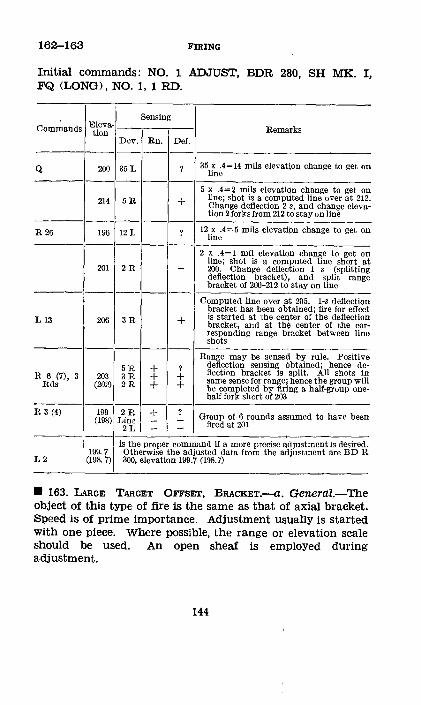
162-163 FIRING
Initial commands: NO. 1 ADJUST, BDR 280, SH MK. I, FQ <LONG>, NO. 1, 1 RD.
Sensing Co=ands Eleva· Remarks tion
Dev. Rn. Def. -----
Q 200 35 L ? 35 x .4=14 mils elevation change to get on line
-----5 x .4=2 mils elevation change to get on
214 5R + line; shot is a compqted line over at 212. Change deflection 2 $, and change eleva-tion 2 forks from 212 to stay on line -----
R 26 196 12 L ? 12 x .4=5 mils elevation change to get on line
-----2 x .4= 1 mil elevation change to get on
201 2R line; shot is a computed line short at - 200. Change deflection 1 s (splitting deflection bracket), and split range bracket of 200-212 to stay on line -----
Computed line over at 205. 1-s deflection bracket has been obtained; fire for effect
L 13 206 3B: + is started at !;he center of the deflection bracket, and at the center of tbe cor-responding range bracket between line shots
-----Range may be sensed by rule. Positive
5E: + ? deflection sensing obtained; hence de-R 6 (7), 3 203 3E: + + flection bracket is split. Ail shots in
Rds (202) 2E: + + same sense for range; hence the group will be completed by firing a half-group one-half fork short of 203 --
R 3 (4) 199 2H + ? Group of 6 rounds assumed to have been (198) L~nL I - - fired at 201 - ---· is the proper command if a more precise adjustment is desired.
199. 7 Otherwise the adjusted data from. the adjustment are BD R L2 (198. 7) 300, elevation 199.7 (198. 7)
• 163. LARGE TARGET OFFSET, BRACKET'.--a. General.-The object of this type of fire is the same as that of axial bracket. Speed is of prime importance. Adjustment usually is started with one piece. Where possible, the range or elevation scale should be used. An open sheaf is emploYed during adjustment.
144
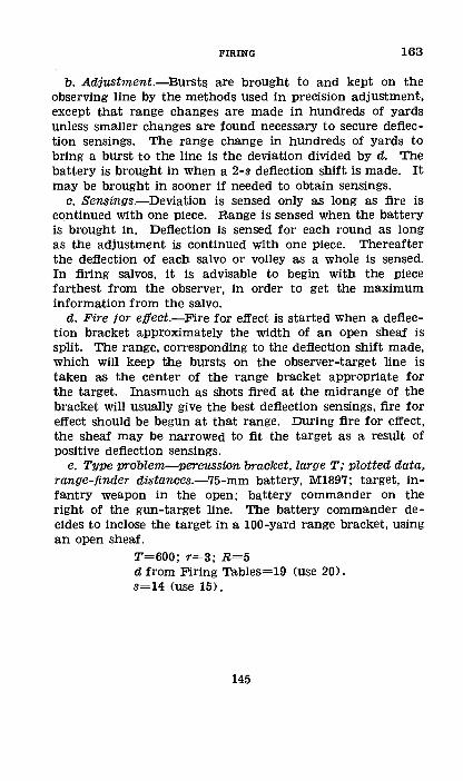
FIRING 163
b. Adjustment.-Bursts are brought to and kept on the observing line by the methods used in precision adjustment, except that range changes are made in hundreds of yards unless smaller changes are found necessary to secure deflection sensings. The range change in hundreds of yards to bring a burst to the line is the deviation divided by d. The battery is brought in when a 2-s deflection shift is made. It may be brought in sooner if needed to obtain sensings.
c. Sensings.-Deviation is sensed only as long as fire is continued with one piece. Range is sensed when the battery is brought in. Deflection is sensed for each round as long as the adjustment is continued with one piece. Thereafter the deflection of each salvo or volley as a whole is sensed. In firing salvos, it is advisable to begin with the piece farthest from the observer, in order to get the maximum information from the salvo.
d. Fire tor effect.-Fire for effect is started when a deflection bracket approximately the width of an open sheaf is split. The range, corresponding to the deflection shift made, which will keep the bursts on the observer-target line is taken as the center of the range bracket appropriate for the target. Inasmuch as shots fired at the midrange of the bracket will usually give the best deflection sensings, fire for effect should be begun at that range. During fire for effect, the sheaf may be narrowed to fit the target as a result of positive deflection sensings.
e. Type problem-Percussion bracket, large T; plotted data, range-finder distances.-75-mm battery, M1897; target, infantry weapon in the open; battery commander on the right of the gun-target line. The battery commander decides to inclose the target in a 100-yard range bracket, using an open sheaf.
T=600; r=3; R=5 d from Firing Tables=19 <use 20). s=14 <use 15).
145

163-164 FIRING
Initial commands: BDR 200, CV AT 5,000, ON NO. 1 OP 6, SI 0, SH MK. I, FQ, NO. 2, 1 RD.
Sensing
Commands Range Remarks Dev. Range Def. ·-------
5000 55R ? 55/20=3 ·-------
4700 20 L - 20/20= 1 Line short at 4$00 --------
L30,BL 5000 --?- -·------
L30 5200 ??++ + --------R 15 5100 ?--? ---------L8,B1 Rd 5150 The battery commander improves
5100 deflection as positive senslngs are 5200 obtained
• 164. TARGET OFFSET GREATER THAN 1,300 MILs.-a. When T is greater than 1,:300 mils, the range change to bring a burst to the line may be determined by the mil relation. For example: T=1,400; r=2; an observed deviation is 50 mils; the range change necessary to bring the shot to the line is 50X2=100 yards. The initial deflection bound also is determined by the mil relation. Example: R=5; the estimated deflection error of initial data is 400 yards; the initial deflection bound is 400/5, or 80 mils. The target is bracketed for deflection and the bracket split successively.
b. Instead of using s-bounds to stay on the line (par. 162 b (2)), the range change for a given deflection change may be determined by the formula: Range change in yards=deflection change in yards X tangent (1,600-T').
c. In the example in a above, the range change corresponding to a deflection bound of 80 mils may be calculated as follows:
80 mils,=400 yards. 400 X tangent 200 mils=400 X .2=80 yards.
146
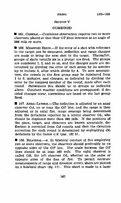
FIRING 165-168
SECTION V
COMBINED
• 165. GENERAL.--Combined observation requires two or more observers, placed so that their OT lines intersect at an angle of 300 mils or more.
• 166. MEASURED E'RROR.-If the error of a shot with reference to the target can be measured, deflection and range changes are made to bring the next shot to the target. Thereafter, groups of shots <usually six in a group) are fired. The groups are numbered 1, 2, and so on, and the changes made are determined by dividing the error of each group by its number up to include 4, after which divide by 4. To save ammunition, the rounds in the first group may be numbered from 1 to 6, inclusive, and changes, as indicated by dividing the error by the assigned number of the round, made after each round. Subsequent fire should be in groups as indicated above. Constant weather conditions are presupposed; if decided changes occur, corrections are based on the last group fired.
• 167. Axl:AL-LATERAL.-The deflection is adjusted by an axial observer OA, on or near the GT line, and the range is then adjusted as in axial fire, range sensings being determined from the deviations reported by a lateral observer OL, who should be displaced more than 300 mils. If the positions of the piece, target, and observers are known accurately, deflection is corrected from OA reports and then the elevation correction for each round is determined by multiplying OL deviations bY the factor C/d (par. 162 b).
• 168. BILATERAL.--a. In bilateral conduct of fire employing two or more observers, the observers should preferably be on opposite sides of the GT line. The angle between the OT lines should be at least 500 mils. The right observer is called OR, the left observer OL, whether on the same or opposite sides of the line of fire. To permit accurate measurements of range and direction errors, shots are plotted on a bilateral chart (fig, 17). This chart is made to a large
147
168-169 FIRING
scale, preferably 1: 2,000; hence, usually it shows only the target area.
b. The chart is constructed as follows: (1) Draw a vertical line representing thet GT line and
near the center indicate the target. Through the target draw lines representing the OT lines of the observers. For example, GT range is 10,000 yards; OR-T distance is 5,000 yards, with a T of 300 mils; OL-T is 4,000 yards, with a T of 400 mils.
(2) Through the target draw a line perpendicular to the GT line G'G', and lines perpendicular to each ·oT line R' R' and L' L'. With the target as an origin, graduate the GT line in 100-yard intervals, to the scale of the chart. Lay off on G'G', on both sides of the target, intervals representing 5-mil deflection shifts, using the same scale· as before and applying the mil relation. The amount of this interval in yards is, in the example, 5 X 10=50 yards. R' R' and L' L' are graduated in a similar manner for 5-mil deviation intervals. The interval in yards on R'R', irr the example, is 25 yards; on L' L', 20 yards.
(3) Through the graduations on G'G', draw lines parallel to GT; through those on L' L', lines parallel to OL-T; and through those on R' R', lines parallel to OR-T.
(4) A shot is fired, the reports of the observers are transferred to the chart, and the intersection of the deviation lines locates the position of the shot. The error in deflection and the error in range are read by inspection with reference to GT and to G'G', respectively, and the adjustment is made as indicated in paragraph 166. For example, OR reports, "20 right"; OL reports, "13 right." The shot is plotted as shown and is seen by inspection to be 8 mils right and 60 yards over.
• 169. CENTER-0!'-IMPACT AnJUSTMENT.--a. General.-A center-of-impact adjustment is used for :registration when a precision adjustment on an accurately located check point is impracticable. 'I'wo observers are used; for accurate results, their observing lines should intersect at an angle of 500 mils or more. The position of the piece and of each observer must be plotted accurately on the firing chart., Each observer reports the deviation of each round from a designated refer-
148
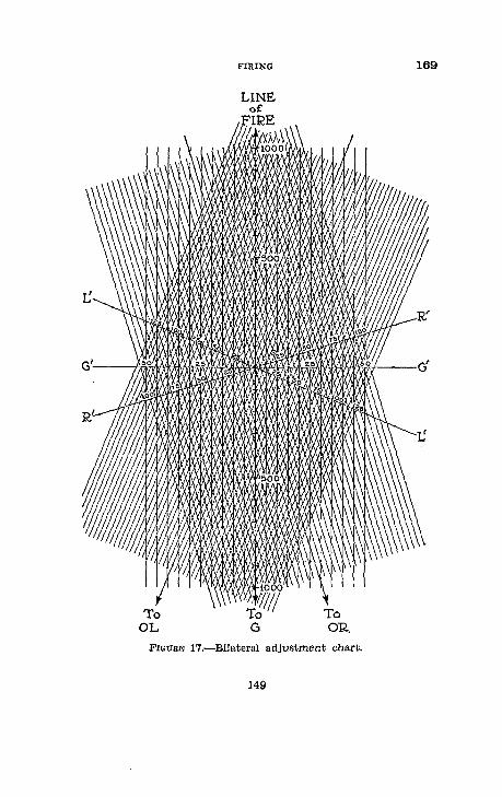
To OL
FIRING
To OR,
FIGURE 17.-BilateraJ adjustment chart.
149
169
169 FIRING
ence point, which also must be accurately plotted on the firing chart. The adjustment consists essentially of determining the center of impact of a group of rounds fired with the same data; this center of impact is taken as the position of a check point.
b. Adjustment.-(!) Preliminary data.-A point is selected in the center of the target area, on terrain that is visible to both observers. Observation at night of HE shell bursts on impact is extremely difficult; if an adjustment is to be made at night, the point should be on smooth ground and preferably on a forward slope, otherwise many rounds may be lost because of minor irregularities of terrain. Firing data are computed to place a burst on the point selected, and an instrument direction from a reference point is determined for each observer so that the burst will appear in his field of view.
(2) Procedure.-Each observer sets the azimuth scale of his instrument at. zero, Jays on the reference point with this setting, and then, with the upper motion, lays his instrument in the direction ordered. An orienting round is fired from the registering piece. Each observer, using the upper motioQ, places the vertical hair of his instrument on the burst and reports its deviation from the reference point. If the burst is not visible to both observers, the battery commander changes the data and fires again, continuing until a burst visible to both observers is obtained. A group of at least six rounds then is fi:red without change of data. Each observer reports the deviation of each round from the reference point. Unless the altitude of the check point can be determined from a map, at least one observer reports the site of each round. If no communication is availabl{~, the rounds are fired on a prearranged time schedule. In this case, each observer records the deviation of each row1d, noting lost rounds in their proper sequence.
c. Data tram the adjustment.-The battery commander calculates and plots the mean deviation of the rounds as reported by each observer, excluding the orienting round and the rounds not reported by both observers. The intersection of these two rays is the map location of the check point.
150
FIRING 169-170
The adjusted deflection is the deflection at which the group of rounds was fired. The adjusted range is the range corresponding to the quadrant elevation at which the group of rounds was fired, after the range has been corrected for position effect or the elevation corrected for site and complementary angle of site (par. 139 f (6)). The map shift and map range for the check point (located by firing) are measured; the deflection correction is determined (pars. 128 and 131), and a K or VE is computed.
• 170. HIGH-BURsT ADJUSTMENT.-a. General.-A high-burst adjustment is used for registration when registration on a ground check point is impracticable. It is similar to a center-of-impact adjustment (par. 169), except that the check point is in the air. Two observers are used; for accurate results, their observing lines shoUld intersect at an angle of 500 mils or more. Usually one of the observers is axial with his instrument near the registering piece. The adjustment consists essentially of locating vertically and horizontally the burst center of a group of rounds fired with the same deflection and quadrant elevation; this burst center is taken as the position of the check point. The time of burning of the fuze may be varied during the adjustment by changing the fuze range or corrector without affecting the results. Laying for elevation is with the gunner's quadrant.
b. Adjustment.-(!) Preliminary data.-Firing data are computed to place a burst at a point near the center of the target area at such a height that all bursts not erratic wili be visible to both observers. These data are computed as follows:
(a) Deflection, as measured on the firing chart and corrected for drift.
(b) Corrector, usually the center of the corrector scale. (c) Fuze range or time, the range setting to the nearest
50 yards equivalent to the map range. If the fuze setter is graduated in time, the time corresponding to the map range is used.
(d) Quadrant elevation, the elevation corresponding to the map range plus a site necessary to place the burst at a suitable height. The site should be as low as possible consistent
151
170 FIRING
with the ability of both observers to see all rounds. It usually should be about 15 mils greater than the site of the mask at the battery position (assuming an axial observer).
(e) An instrument direction from a reference point and a site to the computed burst center are determined for each observer.
(2) .Procedure.-Each observer sets his observing instrument in the computed direction and with the computed site. An orienting round is then fired and each observer places the vertical hair of his instrument on the burst. The axial observer reports the deviation from the reference point, and the site; the lateral observer reports the deviation from the reference point. If the burst is not visible to both observers, the battery commander changes the data <usually the corrector or fuze range) until a satisfactory burst is obtained. Thereafter, a group of at least six rounds is fired without a change of quadrant elevation or deflection. The axial observer reports the deviation and the site of each round; the lateral observer reports the deviation only. If neither of the observers is near the piece, one of the observers reports deviation and site; the other, deviation only.
c. Data from the adjustment.-The battery commander plots the mean deviation of the group of rounds as reported by each observer, excluding the orienting round and rounds not observed by both observers. The intersection of these two rays is the horizontal map location of the check point. The site of the check point is determined from the mean of the site readings reported. If the observer reporting site was not near the piece, the altitude of the check point is computed and its site from the piece calculated. The adjusted deflection is the deflection at which the group of rounds was fired. The adjusted range is the :range corresponding to the quadrant elevation at which the group of rounds was fired, after correcting the elevation for the site (and complementary angle of site) of the burst center, or by correcting the range for the position effect for the difference in altitude of piece and burst center. The map shift and the map range are determined from the firing chart. The direction correction is determined and a K or VE is computed.
152
FIRING 171-174
SECTION VI
ADJUSTMENT WITH SOUND-AND-FLASH UNITS
• 171. GENERAL.-The primary mission of observation (soundand-flash) units is the collection of information, particularly the location of enemy batteries; a secondary mission is the adjustment of artillery fire, normally for medium and heavy artillery.
• 172. SoUND RANGING.-A sound-ranging adjustment is most effective when the target is located by sound ranging and the adjustment by sound ranging on the projectile follows immediately. The sound-ranging officer informs the battery of the coordinates of the target, the number of rounds to be fired, and the interval between rounds. The battery commander prepares data for the target, at the proper time reports, "Battery ready," and fires at the signal FIRE of the sound-ranging officer. The sound unit reports the error of the center of impact of the group as (so many) yards east or west and (so many) yards north or south of the target. The battery commander corrects his data accordingly and fires the next group without signal. The adjustment continues in this manner until the sound-ranging officer signals ADJUSTMENT COMPLETED. Normally, a group of two rounds is sufficient to determine a trial elevation and a group of six rounds to determine the adjusted elevation. In fire for effect, the battery commander should use a safety factor of 50 yards.
• 173. FLAsH RANGING.-The procedure is the same as for a sound-ranging adjustment. The flash-ranging officer reports the error of each group of shots, the battery commander making compensating changes.
• 174. REGISTRATION.-For registration with the assistance of a flash-ranging unit, the method is usually the location of the center of impact (par. 169) or the location of the burst center (par. 170). The battery commander furnishes the flash-ranging unit the coordinates of the point for which data have been computed. At the end of the firing, the flashranging officer furnishes the battery commander the coor-
153
174-178 FIRING
dinates of the center of impact or burst center, and in the latter case, the altitude of the burst center;
SECTION VII
CONDUCT OF FIRE WITH AIR OBSERVATION
• 175. COMMUNICATION.--Communication is normally by twoway radio supplemented by the authorized emergency methods. The Fire-Control Code or Air-Ground Liaison Code is used .
• 176. PRELrMINARY ARRANGEMEJ!VI'S.-A COnference between the observer and the officer conducting the fire is desirable. The following instructions should be given the observer:
a. Location of battery positions. b. Location of panel stations, call letters, and frequencies
of radio stations. c. Code range, reference point, base point, or other method
to be used in designating targets. d. Assigned targets when such can be foreseen. e. Methods of fire if other than normal. /. Mission of the artillery unit, its fleld of fire, and the
nature of its targets .
• 177. PREPARATION BY THE BATTERY.-·Before the observer reports for observation, it is desirable that the battery be adjusted to obtain a uniform distribution and preparations made to insure a prompt opening of fire when the observer appears .
• 178. DESIGNATION OF TARGETS.-a. General.-Previously assigned targets a:re referred to by the designation arranged during the preliminary conference. Targets discovered by the observer may be designated by coordinates from a map, firing chart, or air photo; by reference to some terrain feature; by dropping a marked map or photo; by reference to a prearranged reference point or eheck concentration; by calling for fire on the base point and then giving the location of this fire with reference to the target; or by having the battery lay on the airplane for direetion, and then sending a code range or the altitude of the airplane, from which
154
FIRING 178-180
the battery commander computes the range by the mil relation after measuring the site of the airplane.
b. Examples.-(!) Battery in action at 6,934. (2) Enemy infantry concentration, 500 yards north 300
yards west of hill 204. . (3) Reference point (is) 500 right, 1,000 over; hostile
reserves. (4) Mark base point . .....:The battery commander fires on his
base point or with arbitrary data on a point in the middle of his sector at a convenient range, using smoke shell if available. The observer then reports the error of this round with respect to the target; for example, "200 right, 500 short."
(5) Lay on me, altitude 4,000.-The battery commander replies, "Will lay on you." The airplane flies along the GT line and, when directly over the target, the pilot makes a short climbing turn or the observer fires a distinctive pyrotechnic signal. An instrument or the panoramic sight of the piece is used to lay on the airplane for direction and to measure the site. The altitude, which is given in feet, is reduced to yards and the range determined by the mil relation.
(6) Lay on me, 400 less.-The range given is so much more or less than a previously agreed upon code range.
• 179. PROCEDURE.-a. After a target on which the observer desires to adjust has been reported to the artillery, the observer signals WILL ADJUST. If the artillery commander does not wish to adjust on the target by air observation, he signals NO. If he does want air observation, he signals WAIT A FEW MINUTES, and, at the proper time, BATTERY READY.
b. When the observer does not signify that he will adjust, the artillery commander takes either of the following actions:
(1) If he does not desire to adjust on the target, he signals MESSAGE RECEIVED.
(2) If he wants to fire on the target at once and desires the assistance of the air observer, he signals REQUEST ADJUSTMENT ON TARGET JUST REPORTED .
• 180. TYPES OF ADJUSTMENT.-The type of adjustment Used depends on the type of fire suited to the target (bracket or precision), the expected accuracy of the initial data, the visi-
155
180-181 FIRING
' bility of the target, 9lld the time available both to the observer and to the battery for completion of the adjl.).Stment. There are three types; bracket, ladder bracket, and precision.
a. Bracket adjustment is normal and is used when no type is specifically de,signated. When necessary, it may be requested by the code group, bracket adju.stment.
b. Ladder bracket adjustment is used when initial data are determined by inaccurate methods, or when the direction of fire of the adjusting battery is not fixed clearly in the mind of the observer. This method has the advantage of laying down on the ground a scale for measuring errors. It may be specified by the eode group, ladder.
c. Precision adjustment is seldom used. with air observation except when the larger calibers adjust on important targets. It is designated by the code group, precision; adjustment.
• 181. BRACKET F'IRE.-a. Preparation. ot 'fire.-<1) General.-When the target has been previously assigned, the battery is laid by the most accurate method possible, preferably by a transfer of fire. There must be no delay after the observer reports. When a target has been discovered and reported by an air observer, it is essential that data be computed promptly. Great accuracy of initial laying is of little importance; speed is essential.
(2) Direction.--The deflection is computed to place No. 1 piece on the ;r:ight of the target.
(3) Sheat.-The deflection difference is that for a 90-yard sheaf.
(4) Site.-The site can be computed only when a map is available; otherwise, the site of the ta.rget is estimated or is assumed to be zero.
(5) Ammunition.-(a) HE shell with a type of fuze appropriate for the target usually is used for adjustment and fire for effect.
(b) The use of smoke shell at the beginning of the adjustment is desirable if the initial data are inaccurate, if there is much artillery fire in the vicinity of the target, if visibility is poor, or if for other reasons there is likelihood of the round being lost. Usually HE shell is substituted as soon as the fire has been brought near the target. Smoke shell may be specified by the observer.
156

FIRING 181
(6) Method of fire.-The method of fire is always battery right. For the initial salvo, the battery commander commands: AT MY COMMAND, and fires as soon as the observer sends FIRE. When the battery fires, the battery commander signals BATTERY FIRED. If the time of :flight is short and no delay is expected, the battery commander may signal BATTERY FIRED, immediately after the command for range is sent to the battery. Normally, the command FIRE is sent by the observer only for the first salvo; thereafter the battery commander fires as soon as he can apply the correction. If observation is intermittent or if for other reasons the observer desires the battery to fire each salvo at his signal, he sends AT MY coMMAND after each observation; the battery is reported ready and fires on the observer's command.
b. Adjustment.-(!) General.-(a) The observer locates the target and the GT line and determines a tentative scale on the ground from study of a map or knowledge of the ground. By use of this scale he estimates the amounts of range and deflection errors.
(b) The sequence of sensing is the same as that of announcing fire commands. No announcement is made of an element which is correct, except for range.
(c) Individual errors are not reported unless great enough to waste the fire of the piece or pieces concerned and then only after the same error has been observed in two or more successive salvos.
(d) The battery commander keeps a record of sensings and commands, correcting each element of data as the sensing on that element is received. The correction always corresponds to the sensings, even though the sensing is not consistent with what has gone before.
(2) Unobserved rounds.-(a) If the observer does not see the shots because of his faulty position, he reports, "Not in position to observe." The battery commander repeats the fire with the same data.
(b) In case the observer is in position to observe but does not see the shots, he reports, "Lost." The battery commander changes his data by an arbitrary amount in the direction most likely to increase the probability of observation, or fires
177568°-39--11 157
181 FIRING
with the previous data, using smoke shell, and reports to the observer, "Smoke ~;hell."
(3) Directian.-·The observer senses the right of the sheaf with respect to the right of the target. The sensing is given to the nearest 10 yards; for example, "70 left." If the error is less than 10 yards, the sensing is given as "Left (right)." The battery commander makes a deflection change in .the opposite sense by an amount equal to the direction error divided by R.
(4) Sheat.-If the width of sheaf is not suitable, the observer reports, "Sheaf too wide <narrow)." The battery commander closes (opens) on No. 1 piece an arbitrary amount. The sheaf is modified until it is correct. The total amount of closure is never grea'ter than that for a converged sheaf.
(5) Range.-The range error of the center of impact is sensed to the nearest 100 yards; for example, "300 over." If less than 100 yards, the error is reported as "over (short)." A mixed salvo or volley is reported as "mixed over (short)." If the observer does not desire the range changed, he sends REPEAT RANGE. If all elements of data are correct, the observer reports, "Target." If 'the desired bracket has not been established and the observer reports "Over" or "Short," the battery commander changes his range 100 yards in the proper direction and fires a salvo. If a mixed over <mixed short) is reported, the battery commander assumes the center of his bracket as being 50 yards short o.f <over) the last range fired. If bracketing or target is reported, the battery commander assumes this last range fired as the center of the bracket when the target has depth; otherwise he fires for effect at that range until a.dditional information is received. In general, the size of the range bracket to be established and the zone to be searched are the same as in ground conduct of fire.
c. Procedure tollawing adjustmen.t.-(1) In general, the battery commander applies corrections equal and opposite to the observer's reports until he has the daLta necessary to fire for effect. The adjustment usually is followed immediately by zone fire for efl[ect.
(2) On completion of the adjustment, the battery commander notifies his battalion commander of that fact or,
158
FIRING 181-182
acting on instructions which he has previously received, sends the observer one of the following messages:
(a) Will fire fox effect.-This report is sent if he desires the observer to report on the effect of his fire. For the light calibers, the observer usually reports the sense of the preponderance of fire; for the medium and heavy calibers, he often reports the sense of each volley. Data are modified, when desirable, in accordance with the observer's reports. Fire continues until the amount of ammunition allotted or warranted by the nature of the target has been expended or until the observer reports, "Mission accomplished."
(b) Change target.-Upon receipt of this report, the observer adjusts on another target previously assigned or searches for a new target. At the completion of fire for effect, the observer may signal CHANGE TARGET, and report the location of the last fire with respect to the new target.
(c) No further need of you.-This report is sent on completion of a mission. Upon receipt of this message, the observer calls the headquarters of the highest artillery organization to which he is assigned, reporting, "Mission completed."
(3) The commander of the artillery organization to which the airplane has been assigned, upon completion of the observer's missions, sends GO HOME.
d. Observation interrupted.-If observation is interrupted before adjustment is completed, fire for effect may be started, covering a greater area than would otherwise be needed. There is no definite rule for the size of the areas to be covered. The battery commander should take into consideration the nature and importance of the target and the information received from the observer before the interruption occurred, in determining whether fire for effect is justified and, if so, the depth of the zone to be searched.
• 182. LADDER BRACKET F'IRE.--a. Preparation oj fire.-In general, the initial data are determined as for bracket fire (p"Otr. 181 a). The following are exceptions:
(1) Distribution.-The fire is converged on No. 1 piece. (2) Ammunition.-smoke shell is particularly desirable,
since the loss of one round makes accurate sensing for range impossible.
159
182-183 FIRING
(3) Range.-The range for each piece, aft~r No. 1, is increased progressively 200 yards.
b. Ar!iustment.--The adjustment is carried on as in bracket adjustment.
(1) The observer senses the direction with respect to the right of the target and the range error of the center cf impact of the ladder.
(2) The use of the ladder may be diseontinued when the battery commander notes that the fire is near the target; usually, when the direction error does not exceed 100 yards and the range error does not exceed 400 yards. The adjustment is then continued as in a bracket adgustment. The sheaf is opened on No. 1 piece to 90 yards.
c. Fi:re tor etJect.-(1) On a :fleeting target, the battery commander may start fire for effect when the direction error has been sensed as 100 yards or less and. the range error as 400 yards or less; that is, when one shot of the ladder has struck within 100 yards of the target in direction and range.
(2) If smoke shell is used in the initial adjustment, the sensing of at least one salvo fired with the type of ammunition which will be used in fire for effect usually is essential because of the d:ifferences in ballistic qualities of the two types of ammunition.
• 183. PRECISION F'IRE.--a. GeneraZ.-Pr43Cision fire may be either by a single piece or by battery, In general, the initial data are determined as in bracket fire (par. 181).
b. Arliustment by single piece.-The procedure follows ground conduct o1' fire except that range bounds are made in terms of c instead of forks, until a trial elevation is determined. The observer senses each round with respect to the adjusting point or the center of the target. When a trial elevation has been obtained, the battery commander begins fire for effect, signaling BY SERIES OF 3 RO'UNDS. The observer senses the de:flection of the half-group and the range error of each round; for example, "20 right, mixed over <over, over, short)." A second half-group of three rounds usually completes the adjustment.
c. Arliustment by battery.-The method of fire is BATTERY
RIGHT AT FIVE SECONDS. If the error of the initial salvo is
160
FIRING 183-185
large, the observer senses the salvo as a whole, as in bracket adjustment. When fire has been brought near the target, the observer senses each round with respect to its proper part of the target. The battery commander adjusts each piece independently from a record of the sensings. The adjustment is carried only so far as circumstances permit. Volley fire for effect then is used, the observer sensing the general effect of the fire .
• 184. RECORDING AN ADJUSTMENT.-When a battery completes fire following an adjustment with air observation and the battery probably will be called on to fire later on the same target with unobserved fire, the procedure is as follows:
a. Immediately following fire on the target, an adjustment is made on a check point, using ground observation. The check point should be as near the target as practicable. It need not be located on a map. The adjusted defiection and range of the check point and of the target are recorded.
b. Immediately preceding a second firing on the target, an adjustment is made on the check point. The deflection and range corrections found necessary for the check point are applied to the recorded data on the target, thus giving the new initial data for the target .
• 185. SURVEILLANCE OF F'IRES.--a. The observer may be given the mission of reporting the effect of schedule fires (barrages and concentrations). The commander of the artillery organization must arrange to transmit reports promptly from the radio station direct to the battery. The observer must be given the objectives, the time of firing, and, if practicable, the direction of the GT line for each objective.
b. When the observer sees fire that is ineffective, he reports the error of the fire as a whole with respect to the center of the target; for example, "No. 345, 50 left, 100 over" (meaning that fire on target No. 345 is 50 yards left and 100 yards over). These corrections are applied by the battery commander, Usually the corrections are applied to succeeding concentrations by K-transfer methods.
o. If it is impracticable to report errors with respect to the GT line, the observer may refer· to grid direction; for ex-
161
185-186 FIRING
ample, "No. 345, 501 east, 100 south." The battery commander plots the location of the center of impact as reported and detennines the del:tection and range corrections .
• 186. BALLOON OBSERVATION .--a. Characteristics. -Factors which influence the use of balloon observers for artillery missions include the following:
(1) The balloon is extremely vulnerable to attack bY. enemy aircraft.
(2) The observer may be hampered by unfavorable weather conditions.
(3) The number of balloons available is limited. <4> The distance from the observer to the target is great,
making a close precision adjustment impracticable. However, the observer is able to use field glasses.
(5) The observer in the balloon does not have the vertical view possible to the airplane observer. Since his position is high, however, most of the enemy terrain is visible and he can estimate the amount as well as the sense of the errors in most cases.
(6) Observation is continuous and telephone communication to the batteries reliable. Hence, there is little probability of misunderstandi.ngs or failures.
'b. Methods.-(].) Adiustments.--Because of vulnerability of the balloon, adjustments must be rapid; usually bracket or ladder bracket.
(2) Procedure.--Generally the procedure is the same as described for the airplane observer. The balloon observer often will be carrying out missions for more than one unit; hence coordination is important.
(3) Sensings.-(a) When practicable, the observer senses with respect to the GT line.
(b) The observer may report errors with respect to grid directions.
(c) The observer, when necessary, may report errors with respect to the· balloon-target line. The battery commander, knowing the relative position of the balloon and battery, plots and interprets the sensings.
162
FIRING 187-180
SECTION VIII
CONDUCT OF FIRE BY AIR-OBSERVATION METHODS, USING GROUND OBSERVERS
• 187. GENERAL.-With forward observation, fire may be conducted at the battery or battalion observation post bY airobservation methods. The forward observer senses and reports errors. This section covers primarily the duties of the observer .
• 188. PRELIMINARY ARRANGEMENTS.-80 far as conduct Of fire is concerned, tpe following information is given the observer before he goes forward:
a. Any special missions. b. A list and description of the base points (if more than
one), the battalion reference points, and such check points and check concentrations as have been designated.
c. If a map or photo is available, that of the forward observer should have plotted on it the above-mentioned points and, in addition, all concentrations which have been planned by his unit.
d. Information as to locations of batteries, although not essential, will expedite adjustment .
• 189. DESIGNATION OF TARGETS.--a. The location Of the targets may be given by any of the following methods:
(1) By concentration number when the target coincides with a prepared concentration or check concentration; for example, "Concentration 15, working party, will adjust."
(2) By reporting the target with reference to some identifiable point such as a base point, a reference point, a numbered concentration, a check concentration, or a terrain feature; for example, "(Check) concentration No. 40 (is) 300 left, 400 short, (of) machine guns, will adjust." Should an observer desire to identify a check concentration on the ground, he may call for fire thereon; for example, Mark (check) cancentratian:. No. 40. A battery salvo fired with data taken from the observed-fire chart will indicate its location for all practical reference purposes. When a satisfactorY reference point is· not available, the observer may call for a
163
189-190 FIRING
round of smoke in the center of the sector byan appropriate code message, and sense this round with respec;t to the target.
(3) By coordinates from a map or gridded photo; for example, "Coordinates 5569, infantry weapons, will adjust."
b. In the designation of targets, the observer must give a description sufficiently complete to enable the artillery commander to determine the allotment of ammunition and the number of batteries to be used. If the target is of such size and importance as to require the fire of more than one battery, the observer includes in his report, "Request battalion," or "Request two batteries."
B 190. PROCEDURE .. --a. When an observer desires to call for artillery fire, he sends a message to the artillery commander, describing and locating the target in the manner indicated in paragraph 189,. including the words "will adjust" if such is the case and fire is desired.
b. If it is decided to have the observer adjust the fire, he is furnished the following information:
<1) Concentrat:ion number to be assigned to the particular mission.
(2) Number of batteries to fire the mission. (3) Designation of battery or batteries to fire. <4> When the adjusting battery is ready to fire its initial
salvo. c. The observer reports the errors of 'each salvo in direc
tion and range. The errors are reported in yards with respect to the general line gun-target. Until the observer is well oriented by previous firing or by a study of available maps or air photos, it is advantageous to sense a single element (either range or deflection) for each salvo until the bursts are near the target. The general principles of a bracket adjustment are applicable. The adjustment proceeds as in air observation until the observer considers the adjustment satisfactory and sends FIRE FOR l~FFECT, or until the officer conducting fire is satisfied with the adjustment.
d. The observer watches the fire for etfect. If he observes that the desired effect has been obtained, he reports, "Mission a.ccomplishecl"; firing then ceases. If the fire for effect
164
FmiNG 190-191
as a whole is not effective, he senses and repor:;s errors. If, upon the completion of fire for effect, the mission has not been accomplished, he may ask that the fire for effect be repeated by the message FIRE FOR EFFECT.
e. When more than one battery is being adjusted, the first battery adjusted commences fire for effect as soon as its adjustment is complete. The second and third batteries fire for effect with data determined from the adjusted data of the first battery. To assist observers in distinguishing the fires of the various batteries in a battalion concentration, the batteries use prearranged different methods of fire for the initial range, followed immediately by volleys for the remainder of the zone. For example: Battery A initially fires battery right; Battery B, battery one round; and Battery C, battery left. If possible, the observer senses the initial effect of the second and third batteries with reference to that portion of the target on which he desires their fire. If no sensing from the observer is received, batteries continue fire for effect without change of data (par. 203 a (1) and c (5) ) .
f. In some situations a radio set may be assigned to a battery; in this event, with obvious modifications in procedure, the observer will work directly with the battery.
SECTION IX
SMOKE
• 191. UsE.---a. Smoke shell is used primarily for blinding enemy observation, either to reduce the effectiveness of hostile action or to conceal movements of friendly troops. To be effective, the fire must be observed. Individual rounds may be used to designate targets or to identify the fire of a particular battery.
b. When smoke is used against weapons emploYing direct laying, it should be placed either on the weapons or on the front edge of the area occupied bY them. The casualty effect on this type of target is appreciable.
c. When smoke is used against observation posts of enemy weapons employing indirect laying, it should be placed short of the point to be obscured.
165
191-194 FIRING
d. When placing smoke, the object of the screen, the action of friendly troops, and weather conditions must be considered.
e. Smoke is used most advantageously when the wind is parallel to the front to be screened. A screen may be built up in a head or rear wind by adjusting each piece on its appropriate part of the front and, from observation of the screen, maintaining the required rate o!f fire. In the case of a head wind, consideration should be given to the effect of the drifting smoke on our own troops, and the supported troops should be consulted before a smoke screen is formed in such circumstances. Smoke shell ordinarily should not be used in a head wind on objectives which are less than 1,000 yards from our attacking troops.
• 192. ACTION OF A BURsT.-8moke from a projectile armed with the quick fuze tends to rise more rapidly than that from
. one armed with the delay fuze. When the delay fuze is used, part of the effect is lost in the crater. Moist ground, cool weather, and little or no wind afford the most favorable condition for smoke .
• 193. BUILDING UP AND MAINTAINING A SCREEN.-The adjustment usually is made with one piece to determine data which will place the bursts in the most favorable position for building up the screen. With most calibers, in a moderate wind, the screen becomes fully effective at about 100 to 200 yards from the point of burst. To build up the screen, several volleys are fired rapidly with the sheaf opened as appropriate for the front to be screened. In a cross wind, as soon as the screen is formed, the battery may be converged to the windward. Continuous fire is employed to maintain the screen. Changes in deflection, range, or rate of fire are made as necessary to thicken any portion of the screen requiring it or to adjust the position of the screen if required because of changing weather conditions.
B 194. AMMUNITIION REQUIREMENTS.-For the purpose of estimating ammunition reqUirements, the following results may be expected from a battery, assuming a wind of about 10 miles per hour and favorable weather conditions:
166
FIRING
Smoke shell, appr~xlmate width of screen
Range wind Cross wind
194-196
Total ronnds
per minute
75-mm battery __________ 100 yards ______________ 400 yards______________ 12 155-mm battery _________ 200 yards. _____________ 1,000 yards____________ 3
With stronger winds and in hot, sunny weather, the abovementioned screens may be maintained only with larger ammunition expenditures. With winds stronger than 20 miles per hour, the difficulty of maintaining screens makes the use of smoke of doubtful value.
SECTION X
GAS
• 195. CHARACTERISTICS OF GASES.--a. Mustard gas (HS) .Mustard gas persists on an area from 5 to 10 days. It is primarily important as a vesicant (blistering) agent; the effects result from contact with the liquid gas on ground or vegetation, or from exposure to an atmospheric concentration. The increase or decrease of the tabular amounts, because of the temperature or the wooded condition of the area, is accomplished in all cases by an increase or decrease of the number of times the area is covered by fire.
b. Tear gas <CNS> .-Tear gas is nonlethal and harassing. It persists for about 1 hour on open terrain in summer but may remain effective longer in cool weather or in dense vegetation, such as woods and standing crops.
c. Phosgene <CG> .-Phosgene is nonpersistent and lethal in ordinary field concentrations. It may remain effective for more than 10 minutes in woods or on low terrain. Its use should be confined to sudden bursts of fire not exceeding 2-minute duration. Phosgene is loaded only in 155-mm howitzer shell .
• 196. REQUIREMENTS FOR NEUTRALIZATION.-The tables shown below give the amounts of different gas shell required for neutralization (HS and CG> or harassing <CNS>, together with data necessary for the proper assignment of missions.
167
196 FIRING
The 200-yard circle is the standard size of concentration, except in the case of phosgene (CG) shell, the 100-yard circle is the standard target area used. For the firing of HS and CNS, larger areas are broken up into standard circles and the necessary number of batteries is assigned. CG is never fired on large areas for casualty effect.
Gas shell---75-mm gun battery
[Area assigned is a circle 200 yards in diameter]
HS (Mustard) Kind of gas ____________
Temp. above 50° F. CNS (Tear gas)
Registra- No regis- Registra- No regis-Conduct of fire by- Obsn tion and tration. Obsn tion and tratlon.
transfer Map data transfer Map data of fire corrected of fire corrected
-------- -----------Ronnds sweeping 1 2 2 2 0 0 0
-------- -----------Range safety factor 0 50 yds. 100 yds. 0 50 yds. 100 yds.
He 1e Hie 1e -------- - --------
Ranges fired in cover-ing the area once 5 7 9 5 7 I)
-------- -----------Rounds required to 40 56 72 20 28 '3tl
cover the area once -------- -----------
Number of times the 8 8 8 1 1 1 area is covered -------- ------------
Total ronnds required to establish required 320 448 576 20 28 3tl density
----------- ------------Time required for one 27min. 37min. 48min. I min. 1~i min. IHmin. battery'
----------- -----------Rate of fire, ronnds per 12 241 battery per minute
' For the purpose of computation, the effective width of burst of gas shell filled with CNS may be taken as 70 yards.
'The time required to fire the necessary number ofrotmds ofHS is based upon the prolonged rat,e of three rounds per gnn per minute, slnee none of the total amonnts above could be fired by one battery in 10 minutes at the maximum rate of six ronnds per gun per minute. The amounts of CNS given are fired I;>y one battery at the maximum rate; the effect lasts for about one hour. CNS is used for harassing purposes to force the wearing of the gas mask.
NOTES
1. To neutralize areas larger than 400 yards by 400 yards with HS (must'lrd), divide the area into 200-yard circles. Fire on each area by registration, transfer of fire methods, but cover the area only four times.
168
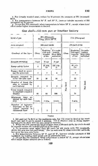
FIRING 196
2. For densely wooded areas, reduce by 25 percent the amounts of HS (mustard) fired.
3. For temperatures between 32° F. and 50° F., increase tabular amounts of BS (mustard) by 25 percent.
4. Do not fire HS (mustard) when temperature is below 32° F., except where later effect under higher temperature is desired.
Gas shell-155-mm gun or howitzer battery
Kind of gas HS (Mustard) OG (Phosgene) Temp. above 50° F.
Area assigned 200-yard circle lOO-yard circle
Registra- No regis- Registra- No regis-
Conduct of fire by- Obsn tion and tration. Obsn tion and tration. transfer Map data transfer Map data of fire corrected of fire corrected
----------- -----------Rounds sweeping None None None
-------- ----Range safety factor 0 50 yds. 100 yds. 50 yds.
He lc He -------- ----
Ranges fired in cover· ing the area once 5 7 9 3
-------- ----Rounds required to
cover the area once 20 28 36 12 -------- ----
"" Number of times the "" " area is covered by Jl <&l
each battery 3 3 3 2 --------- b ---- 0
Total rounds required z z to establish required density 60 84 108 72
---- ----Minimum time re-
quired by each bat-tery 5min. 7min. 9min. 2min.
-------- ----Number of batteries
necessary to fire re-quired amount in minimum time 1 1 1 3
NOTES
1. HS need not be fired at the ma.ximum rate but OG must be fired at the maximum rate and in not to exceed 2 minutes. 0 G is effective only in strong concentrations and its effect lasts for only about 10 minutes.
2. Where the 0 G (phosgene) target is larger than a 10Q-yard circle, the circle should be selected within the upwind portion of the target.
3. To neutralize areas larger than 400 yards by 400 yards with HS (mustard), divide the area into 2uQ-yard circles. Fire on each area by observation-fire methods, but cover the area only twice.
4. For temperatures between 32° F. and 50° F., increase tabular amounts of HS (mustard) by covering each target area an additional time.
5. Do not fire HS (mustard) when temperature is below 32° F., except where later effect under higher temperature Is desired.
169
197-198
CHAPTER 5
TECHNIQUE OF FIRE DIRECTION Paragraphs
SECTION I. GeneraL-------------------·----------- 197-201 II. Support by observed fires _______________ 202-203
III. Schedule fires------------------------- 204-207 IV. Ammunition requirements---·----------- 208-212
SECTION I
GENERAL
• 197. GENERAL.--Within the battalion it is desirable that the technique of fire direction be developed to the points where the battalion commander can maneuver the fire of his batteries with the same relative efficiency that a battery commander maneuvers the fire of his pieces. Both speed and accuracy are characteristic of good fire direction. Speed is of especial importance for the light artillery battalion in direct support .
• 198. FuNCTIONS OF 'l'HE BATTALION COMMANDER IN FIRE DIRECTION.--a. The fire-direction functions of the battalion commander should result in the assigrunent of specific fire missions to the batteries of his battalion. His task is one of translating the more general plans of higher commanders and the general nres requested by the supported unit commander into specific fire missions practicable of execution by the firing units at his disposal.
b. The fire-direction functions of a battalion commander of a light artillery battalion in direct support are for-
( 1) Handling observed fire missions to--(a) Organize observation facilities within. his battalion
with a view to the location of tactical objectives and the maneuvering of fire.
(b) Organ.ize commun.ication facilities so that fire missions originatin.g with any observer can be promptly transmitted to and executed by any fire unit.
(c) Organ.ize his staff with a view to rendering prompt and continuous support.
170
FmiNG 198-200
(d) Determine the amount of fire to be placed on a given objective and to assign batteries to fire.
(2) Schedule fires to--(a) Determine specific fire missions for the batteries, based
upon the more general missions assigned by higher commanders, conference with supported troops, observation of terrain, reports from liaison sections and forward or air observers, and a study of the situation.
(b) Decide specifically, in conformity with approved plans, when fire is to be placed on each objective, the number of batteries to be employed, and the type and amount of ammunition to be used.
(c) Designate the particular battery or batteries to execute each mission, and to assign the missions in a manner and in ample time to permit effective delivery of fire.
(d) Arrange for the execution by other units of artillery of such fire as his batteries cannot execute effectively.
(e) Make necessary decisions with reference to registration, survey, organization of observing facilities for registration, and methods to be used in obtaining corrections for basic data.
c. The technical fire direction functions of commanders of units other than those in direct support vary with the missions of the battalions. With the general missions in mind, the variations in technique become obvious.
• 199. BATTALION STAFF.-Fire-direction activities center in a fire-direction group. The location of this fire-direction group, with the necessary equipment for operating, is called the fire-direction center. The fire-direction center is a part of the command post and includes telephone and radio personnel, the battalion observed fire chart (par. 203), the firing chart, and the necessary personnel of the battalion staff. The personnel of the battalion staff usually consists of 8-3 and one or two additional staff-officer assistants, the sergeant major, a draftsman, and a clerk .
• 200. PLAN FOR F'mE DIRECTION.-The battalion commander's plan for fire direction must be such as to enable him to direct effectively the battalion observed fire missions
171
200-201 FIRING
originating with observers at observation posts, with liaison officers, or with air observers. It must also proVide a flexible scheme of schedule fires, observed if possible, or, if unobserved, effected by transfer of fire after registration or by map data corrected.
g 201. SOURCES OF FIR~ MrssiONS.-A. Fr017'11 higher authority.-In general, higher commanders indicate only where the mass of the fire will be placed and such localities as require special attention to further the plans of the higher infantry commanders. These missions are distributed to. battalions and broken down into appropriate battery targets. · b. From supported units.-A conference .with the commander of the supported unit is essential. The following specific points must be covered: plan of the supported unit commander (par .. 207) ; probable location of front line elements at various times during the action; areas covered by fires of the supported unit; tactical localities particularly threatening to the success of the supported unit; targets which the supported unit commander desires the artillery to. attack; details of signals to be employed; details of schedule fires to include, when practicable, an estimate of the times when such fires will be required; scheme of repeating any fires; plans for special operations; defensive fires; selection of check concen1;rations and points of common reference; and communication between supported and supporting units.
c. Deduced from a study of the sitnation.-Usually the missions proVided in a and b above will utillze the full fire power of the battalion. When time or other contingencies do not permit of the detailed planning with the supported commander, the battalion or higher commander, from his knowledge of the situation, selects certa:ln localities as being of use to the enemy and assigns as targets critical points in such localities.
d. Reported by liaison. officers or forward or air observers.These usually will be definite targets appearing during the action, or requests for changes in schedule fires. The battalion commander, in accordance with the plan of the supported unit commander, must detennin.e whether such missions will be executed and the amount o:f fire to be delivered.
172
FIRING 201-203
e. Reported by ob•servers other than liaison officers or torward or air observers.-These are attacked as the battalion commander may direct.
SECTION IT
SUPPORT BY OBSERVED FIRES
• 202. PRmciPLES OF PROCEDURE.-Targets Which are located by observers and on which observed fire can be placed are usually reported by liaison o:fficers, ground observers, and air observers. These are principally targets of opportunity. Speed is essential; data are corrected by observation. The following general principles govern:
a. The observer who discovers a target adjusts or conducts fire on that target.
b. When an observer other than a battery observer discovers a target, he reports the nature of the target and its location to the battalion fire-direction center. Usually the observer is directed to adjul"tt the fire, his reports being converted into fire commands by a battalion staff o:fficer who conducts the fire at the fire-direction center. The observer may be assigned a battery, given direct telephone communication thereto, and directed to conduct the fire of the battery.
c. Within the restrictions imposed by the battalion commander, battery commanders, without specific authority, fire on targets appearing in their normal zones .
• 203. BATTALION OBSERVED· FIRE CHART.--4. General.-The battalion observed fire chart, set up at the fire-direction center, is a special type of firing cha.rt (par. 110), the construction of which is based on data obtained by registration, by survey, from map data, or a combination of these, and is designed to accomplish the following:
(1) Provide a means for the quick determination of initial data for the adjustment of fire by forward, liaison, or air observers; and data for the concentration of the fire of the battalion after one battery has been adjusted on the target.
(2) Provide a convenient and accurate means for recording adjusted data on various targets.
177568°-39--12 173

203 FIRING
b. Construction.-0> The observed fire chart may lle constructed on a duplicate of the firing chart used for the assignment of schedule fires, on a grid sheet, or on a plain sheet of paper. It usually is preferable to have the observed-fire chart separate from the firing chart.
(2) The base point or points, check concentrations, and other points which may be used by· observers in designating targets are plotted on the chart. When the true locations of these points are not known, the position of a base point is selected arbitrarily on the chart, and the other points plotted relative to it.
(3) The plotted locations of battery positions on the observed-fire chart are usually based on adjusted data obtained by registration of each battery on an identified point, normally a common base point. When registration is impossible or is limited to a single piece in the battalion, the true positions must be determined by survey and be plotted.
(4) The type of ammunit~on used for registration is the type to be used in subsequent fires assigned from the observed fire chart. When only observed fires are to be delivered, a bracket adjustment on the base point usually is sufficiently accurate.
(5) Each battery, upon completion of registration on the base point, reports its adjusted compass and quadrant elevation <or adjusted range setting).
(6) The position of each battery is plotted on a back azimuth ray drawn through the base point, the direction of the ray being determined by the adjusted compass. The distance from the base point to the battery position is plotted according to the :range or range setting, assuming a site of zero (or the mean site in the case of a sharply sloping target area) , corresponding to the adjusted quadrant elevation (figs. 18 and 19).
c. Use.-<1> A target may be reported with reference to the base point or a check concentration or, if a grid sheet is used, by coordinates. Adjustment of fire is by air observation methods.
(2) When a target is reported with reference to the base point or other reference point by a forward observer, a bat-
174

FIRING 203
FIGURE lB.-Plotting a battery on the observed fire chart.
175
203 FIRING
lll I
0 BASE POINT
·2··8· 0
W. ADJUSTED RANGE SETTING BASE POINT A- 4600 B- 4400 c- 4450
FIGURE 19.-Completed battalion observed fire chart.
talion staff officer assigns it a number and so notifies the observer, determines the initial data for a battery, and conducts the fire of that battery, converting the reports of the observer into fire commands (pars. 189 and 190).
(3) When a target is reported with respect to a check concentration, the initial deflection and range are obtained by measurement from the chart. Corrections to place the fire on the target are made with respect to the observer's sensings.
(4) A battery having been adjusted on a target, the location of the target is plotted (fig. 20) from the adjusted data and numbered to agree with its original designation (the forward observer numbers the target on his map in accordance with (2) above). Thereafter, using any battery of the battalion, fire may be Placed on the target at any time with little or no adjustment.
176
FIRING 203-205
(5) If the importance of the target is such as to warrant the fire of more than one battery, its location is plotted from the adjusted data of one battery (fig. 20). The shift and range for other batteries may then be scaled directly from the chart (fig. 21).
d. Battery observed fire chart.-Except when acting alone in support of other arms, a battery rarely constructs an observed fire chart.
SECTION III
SCHEDULE FIRES
• 204. GENERAL.-The complete scheme of schedule fires includes the fires requested by the supported unit and those directed by higher authority (pars. 198 band 201). The determination of the number and time of firing of all concentrations planned is dependent upon the batteries, ammuni· tion, and time available. A detailed treatment of schedule fires is found in chapter 3 .
• 205. AMMUNITION ALLOTMENTS.-The amount of ammunition to be expended on a mission is primarily dependent on the size of the assigned area, its tactical importance, the state of ammunition supply, and whether registration is permitted. It may be stated in orders from higher authority. The amount of ammunition allotted is in accordance With the effect desired, usually initial neutralization followed by sufficient rounds to maintain neutralization during the period of the operation for which it is planned to take the target under fire. For the simplification of the task of the bat· tery commander in executing his assigned missions, the allotment for the effect stated above is translatable into terms of the number of times he is required to fire through the standard area, using standard elevation and deflection changes (par. 139). For example, in the case of the 75-mm gun, 112 rounds is assumed to establish neutralization on a 200-yard standard area. This requires the battery to fire through twice; 56 rounds (the amount required to fire through once), repeated at intervals during a given period, is assumed to maintain neutralization on this target once the initial neutralization is established.
177
FIRING
ADJUSTED RANGE SETTING BASE POINT A- -4~600 B- 4400 c- 4450
FIGURE 20.-Plotting a target from the adjusted data of Battery A.
178
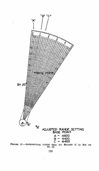
ADJUSTED RANGE sETTING BASE pOINT A- 4600 B- 4400 c- 4400 FIGURE 21.-oetennining initial data tor :Battery C to fire on
NO. 20.
179
206-208 FIRING
• 206. ASSIGNMENT OF MISSIONS.-Missions are usually assigned to the batteries by means of an overlay (par. 137). Supplementary to the overlay is a time schedule (par. 138), either tabular or graphical. These should reach the batteries in ample time to permit careful, detailed preparation of fire.
• 207. F'LEXIBILITY.-To provide flexibility for a scheme of schedule fires and to admit of close coordination with the actual progress of an attack, it is desirable ,that the entire operation be subdivided into maneuver phases; each terminating with the capture of a critical objective. For example, assume that in a certain situation the infantry regimental commander concludes that in order to reach an objective (as designated by hlgher authority) he must first capture a series of critical terrain features which, from the regimental point of view, are intermediate objectives. He decides on an appropriate scheme of maneuver. The operations necessary to capture each intermediate objective, as well as the final objective, constitute a maneuver phase so far as the infantry regiment and its direct support artillery unit are concerned. Normally a separate schedule is prepared for each of these successive phases, the concluding fires for each phase, which provide defensive fires to cover the Infantry on the objective, usually coinciding with the initial fires for the next. Each series of fires can then be initiated or lifted by prearrangement or on call from the supported unit commander. The schedule is drawn, initially, to conform to the estimated rateand manner of advance of the supported unit with relation to the beginning of each maneuver phase. To insure adapting the supporting fires to variations in the rate of advance, provision must be made for moving the time of the schedule forward or backward and for repeating or eliminating any part of it.
SECTION IV
AMMUNITION REQUIREMENTS
B 208. GENERAL.--This section deals with ammunition requirements and allotments for the various tactical fires. The figures given in the tables should be used as a general guide only; combat experience and other factors may indicate wide departures therefrom.
180
FIRING 209-212
• 209. NEUTRALIZATION WITH HE SHELL.-See section VI, chapter 3.
8 210. DESTRUCTION WITH HE SHELL.-The tables shown below give general guides as to ammunition requirements for destruction and for cutting barbed-wire entanglements, respectively. The amounts listed are based on the following assumptions:
a. That observation is good and continuous. b. That the target is reasonably destructible. c. That the caliber used is capable of destroying the target. d. That the ranges are short or midranges for the weapon
used. e. That the initial firing data are at least as accurate as
map data uncorrected. Destruction of an ob-ject <at effective ranges, dispersion not
excessive)
Number of rounds
Caliber For ad
justment For
effect
75-mm ___________________________________________ _ !05-mm __________________________________________ _ 15.5-mm __________________________________________ _ 240-mm __________________________________________ _
15 15 15 15
85 65 45 25
Cutting barbed-wire entanglements
Range
Yards: 2,500 .. ------··-·-···--······---------···--4,000 _____________________________________ _
7,000 .. ------····------·--···-·----··------
75-mm
Number of rounds
600 800
1, 200
Caliber
105-mm
Number of rounds
475 525 950
Total
100 80 60 40
155-mm
Number of rounds
350 450 700
NOTE.-These amounts are an average to cut a breach 30 yards wide in a band of barbed wire 30 yards deep, on level ground. Increase these amounts by two thirds for each additional 30 yards in depth.
• 211. SMOKE.-See section IX, chapter 4 . • 212. NEUTRALIZATION WITH GAS SHELL.-See section X, chapter 4.
181

21"3
CHAPTER 6
DEAD SPACE, VISffiiLITY, AND CALIBRATION
• 213. DEAD SPACE.-<L. Definitians.-(1) Dead space is ground which cannot be reached by fire with the piece and ammunition considered.
(2) The grazing point is a. point at the near limit of dead space where the slope of the ground Is equal to the slope of the trajectory.
(3) The grazing trajectory is the trajectory which is tangent at the grazing point.
(4) The point ot impact of the grazing trajectory is the far limit of dead space.
b. Limitatian.-The determination of dead space is possible only with an accurate contoured map and is consequently of limited application.
c. Determinatian by the quadrant-elevatian method.Draw a ray from 'the plotted position of the piece through the mask. · By inspection, determine the grazipg point of the mask considered. Determine the quadrant elevation of this point. For greater accuracy, determine the quadrant elevations of other points on the ray 50 to 100 yards short or over the initial grazing point tested; the point requiring the greatest quadrant elevation marks the beginning of dead space. The point of impact, or end of dead space, is determined by finding a point beyond the mask which requires the same quadrant elevation as that of the grazing point. A test point of impact is selected by inspection, based on the range corresponding to the elevation for the grazing point and the height of the ground. Its quadrant elevation is determined; if less than that of the grazing trajectory, it is in dead space; i.f greater, it is beyond dead space. By a process of trial and error, the point of impact may be determined to any desired degree of accuracy. ·
d. Determination by the trajectory-diagram method.-0) Description.-The trajectory diagram is a series of trajectories drawn to a horizontal scale of 1: 20,000 and to a vertical scale of 1: 1,200. The altitude of the piece is that
182

FIRING 213
of the central horizontal line; the diagram provides for masks varying from this altitude by 300 feet. Its use is analogous to the profile method of determining visibility.
(2) Graphical use (fig. 22) .-A profile of the ground along the ray tested may be constructed to the same horizontal and vertical scale as the diagram. By superimposing the diagram on the profile in their correct relation, the grazing trajectory is determined; the point where this trajectory strikes the ground marks the far limit of dead space.
(For clarity, only the grazing trajectory is shown)
F'Iot.-nE 22.-Graphical determination of dead space using a trajectory diagram.
(3) General use (fig. 23) .----The graphical determination of dead space as in (2) above is accurate but tedious. The use of the trajectory diagram applies the same principle, but eliminates much of the work. The general use is as follows:
(a) Place the upper edge of the trajectory diagram along the ray to be tested, with the upper left-hand printed corner at the plotted position of the piece.
(b) By inspection, determine the probable grazing point and determine its altitude with respect to the gun. This
183
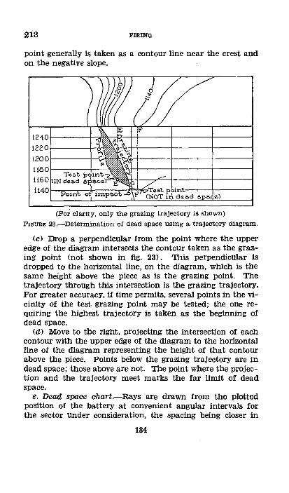
213 FIRING
point generally is taken as a contour line near the crest and on the negative slope.
(For claxit.y, only the grazing trajectory is shown)
FIG1:1RE 23.-Determination of dead space using a trajectory diagram.
(c) Drop a perpendicular from the point where the upper edge of the diagram intersects the contour taken as the grazing point (not shown in fig. 23). This perpendicular is dropped to the horizontal line, on the diagram, which is the same height above the piece as is the grazing point. The trajectory throUgh this intersection is the grazing trajectory. For greater accuracy, if time permits, several points in the vicinity of the test. grazing point may be tested; the one requiring the highest trajectory is taken as the beginning of dead space.
(d) Move to the right, projecting the intersection of each contour with the upper edge of the diagram to the horizontal line of the diagram representing the height of that contour above the piece. Points below the grazing trajectory are in dead space; those above are not. The point where the projection and the trajectory meet marks the far limit of dead space.
e. Dead space chart.-Rays are drawn from the plotted position of the battery at convenient angular intervals for the sector under consideration, the spacing being closer in
184
FIRING 213-215
varied terrain than in comparatively level terrain. Dead space along each ray is determined by either of the methods described. Corresponding points of dead space on adjacent rays are connected. Areas in dead space are hakhed for emphasis. If the chart is made for two kinds of ammunition, the area inaccessible to both is double hatched .
• 214. VISIBILITY CHART.--a. A visibility chart is a map or overlay showing what areas are visible from an observation post. The determination of visibility is possible only when an accurate contoured map is available, and is consequently of limited application. The location of the observation post and a means of orientation must be placed on the chart. When operating in wooded country, an estimated height of the trees is added to the height of the ground as shown by the contours. Visibility shOUld be checked from the ground. When the ranges from an observation post to a target and to an intervening crest, and the altitudes of the observation post, target, and crest, are known, the visibility or invisibility of the target from the observation post, insofar as the intervening crest is a factor, can be determined by applying the following rule: If the angle of site of the intervening crest is algebr:aically greater than the angle of site of the target, the latter will be invisible, and vice versa.
b. To construct a visibility chart, place a piece of transparent paper on the map and draw radiating lines from the observation post through the sector, crossing the points most in doubt. On each ray construct a profile with an exaggerated vertical scale, and on the profiles draw straight lines from the OP, tangent to the highest points of intervening crests or obstacles. The points on these tangents, indicating the limits of the invisible areas, are then transferred to the map. Having transferred these points, the boundaries of the visible and invisible areas are then sketched in on the map.
B 215. CALIBRATION.--a. Definiticms.-(1) Calibration is the comparison of the shooting qualities of a given piece with some standard.
(2) Calibration correction is a correction applied to the .range or elevation setting to make a piece fire in agreement with a reference piece.
185
215 FIRING
b. Procedure.-<1) Preliminary.-All pieces of the battalion are calibrated at the same time and at two ranges, one medium and one long. The pieces should be on level ground, in line, and as close together as practicable. The targets should be located with a site as near zero as possible. The same ammunition lot is used by all pieces, the latter having been boresighted previously. An observing party is stationed at a known distance to the flank of the GT line to determine the range error of each shot.
(2) Firing.-At least seven rounds are fired from each piece at each range as rapidly as is compatible with accurate laying; more than 16 rounds from each piece at each range usually are unnecessary.
(3) Calculation ot mean range.-Disregarding the first round fired from each piece, the mean range is calculated for each piece at each range from the range deviations reported.
(4) Calculation of corrections.-In order that all corrections will be plus, the piece having the greatest mean range is selected as the reference piece. Assume for any other test piece that the range difference was due to difference in muzzle velocity. By use of the firing tables this difference is converted into foot seconds <VE-effect> of muzz:e velocity. The VE-effect is then converted into yards of range effect for each 500 yards of range. The range effects are then converted into mils and the sign changed to plus, thus making them corrections. The correction in mils may be applied either on the angle-of-site scale or on the gunner's quadrant.
(5) Adjustment when using two ranges.-When pieces are calibrated at two ranges, the VE-effect i.s determined for each range. If they do not vary more than 10 foot-seconds, _the mean is used for all ranges. Otherwise, interpolated values are used for other ranges.
(6) Precision adjustment.-When it is impracticable to have a flank ob~;erVing party, each piece may be adjusted by precision methods and the VE-correct.ion determined from the difference in adjusted quadrant elevations.
186
CHAPTER 7
SERVICE PRACTICE
216-218
• 216. GENERAL.-a. The term service practice includes all practice in which subcaliber or service ammunition is fired.
b. Service practice should combine all the basic elements of field artillery training; tactical employment, mobility, signal communication, and firing. This is accomplished best by the employment of tactical field exercises culminating in subcaliber or service firing.
c. Preliminary to service practice, officers should receive adequate training in the conduct of fire by use of blackboard, terrain board, and the field artillery trainer. Also, regimental and battalion commanders should reqUire their officers to attend conferences on the various types of problems to be fired, to assure themselves that all gunnery principles are understood and will be correctly applied.
d. The enlisted personnel of the battery should be well trained in the various duties incident to service practice. A thorough knowledge of safety regulations both for the range and for the materiel is essential for all participants.
• 217. PLANNING.-Careful planning is necessary if the maximum of instruction and profit is to be obtained from the limited allowances of ammunition available. Such planning should take the following points into consideration: relative amounts of service and subcaliber ammunition to be used; illustration of as many different tactical situations as possible; existing proficiency of officers and organizations; illustration of the maximum possible number of different types of fire, with proper emphasis on fire direction, moving targets, air observation methods, and night adjustments; and a logical distribution of progressive training extending over the longest period consistent with local range facilities and with other training objectives.
M 218. PREPARATORY STEPS.-Before firing, all instruments, sights, quadrants, and fuze setters should be calibrated and checked and the guns themselves carefully inspected, paYing particular attention to their recoil mechanisms. Calibra-
187
218-219 FIRING
tions of the guns within a battalion prior :to the practice, while very desirable, usually cannot be secured until the actual firing of precision problems because of the shortage of ammunition. Officers should familiarize themselves with all the safety regulations, War Department and local, that apply to the weapon to be used .
• 219. OFFICER SUPERVISING PRACTICE.--a. The officer superVising the practice (supervisor of fire) bears full responsibility for the organization and progress of firing instruction and for the preparation and safety of the 'range. He may retain to himself, particularly in tactical exercises of his own command involving firing, the function ,of director or he may delegate such functions to qualified officers specially selected. The latter procedure is the rule in technical firing instructions, particularly of groups of junior or inexperienced officers. He may never delegate responsibility for the preparation and safety of the range. When acting as director he critiques the problem; otherwise he presides at the critique, if present.
b. On a. field artillery range used jointly by several different field artillery commands, the responsibilities stated above for the supervising officer, which apply to the preparation and safety of the range, devolve upon the permanent camp commander. The latter assigns a sector to each unit firing separately; the sector designation il}dicates an area in which the batteries may be posted and another area within which targets may be assigned. The officer in command of the unit firing becomes in a limited sensei the supervising officer for the sector assigned to his uni.t.
c. The officer supervising the practice (or, when applicable, the permanent camp commander) will provide a range officer, a range guard, and as many safety officers as may be required for the different firing positions. He is responsible that the personnel provided to insure the safety of the range are suitably informed as to his plans and arrangements and their own duties and responsibilities. In the case of different commands using a common range, he will insure that the officer in charge of each sector is informed as to his sector and the safety requirements of the War Department.
188
FIRING 220-222
• 220. THE DIRECTOR.--a. All field officers and battery commanders should participate yearly in directing and critiquing the firing problems of junior officers.
b. The director selects a target and states a tactical situation which will bring out some definite firing principle. Unless specifically restricted, the officer firing should be made to feel that all personnel and facilities of the battery are at his disposal and that he has full initiative in their employment.
c. During the progress of the problem, the directing officer observes the conduct of fire and stands ready to assist or advise should such action be necessary; the amount of assistance will vary, depending on the experience and temperament of the conductor. Obvious errors, such as adding, when apparently the intent was to subtract, should be corrected to prevent a waste of ammunition; the correction should be given to the battery by the officer conducting fire. The directing officer should never interfere to the extent of giving commands, other than safety commands, directly to the firing battery. If the officer conducting fire appears nervous or embarrassed, the directing officer should refrain from comment or suggestion other than such as will tend to assist the conductor in gaining confidence in himself.
• 221. THE RANGE OFFICER.-The range officer reports for instructions to the officer supervising the practice and, with his range party, prepares, places in positions indicated, and when necessary, operates the target prescribed. He is responsible that the War Department and post regulations concerning the safety of the range are complied with.
• 222. THE SAFETY OFFICER.-The safety officer reports for instructions to the officer supervising the practice. He is responsible that no command is given for firing while the range, so far as is visible to him, is not clear, or while the flag indicating that the range is clear is not displayed by the range officer; that before firing commences and during its continuance the appropriate flag, indicating that the battery is firing or about to fire, is displayed near the guns where it can be seen by the range officer; that the direction in which
177568°-39--13 189
222-225 FIRING
the pieces are laid does not endanger the range or observing parties and· is within the safety limits prescribed by the supervisor of fire .
• 223. STATISTICAL 0BSERVERS.-When feasible, statistical observers should be employed to obtain accurate observation and plotting of all shots fired. These observers include, in addition to those normally employed at the firing point to observe deflections and heights of burst, an observer with the range party to observe range deviations from the target. Duty 'as an observer is excellent training for younger officers, and the detailed report is a valuable aid to instruction at the time of the problem and later in indoor critiques and firing exercises.
• 224. CRITIQUEs.---a. Critiques should be short, impersonal, and above all instructive. They should cover events in the order of their occurrence. Contentions, discussions, and arguments involving unessentials should be avoided.
b. A brief critique should be held by the director at the conclusion of each problem. It should be in general terms and should cover the incidents of firing while they are still fresh in the minds of the officers present. It should include a description of the target, the proper method of attacking it, the effect actually obtained on it, and a concise statement as to why such effect was or was not all that could have been expected. An analysis of every round fired is not profitable.
c. At a later time, a more detailed critique, presided over by the supervisor, should be held. At this critique each commander involved in a phase of the problem should outline the orders he received and his actions based thereon. Frank statements of errors and misunderstandings are essential. The officer conducting the critique clears up doubtful points and then discusses the important features of the problem to· stress the principles involved and indicate their proper application .
• 225. REPORTS OF F'rRING.----;Reports of firing will be SUbmitted in accordance with current regulations and with the instructions given on W. D., 0. 0. Form No. 820 (Quarterly Report of Field Artillery Target Practice) and W. D., 0. 0. Form No. 820A (Quarterly Problem Report of Battery).
190
INDEX
Paragraph Accuracy, definition of____________________________ 4 Action of burst___________________________________ 192 Adjusted compass, commands for__________________ 73 Adjusting sheaf parallel with high bursts__________ 75 Adjustment:
Center-of-impact_____________________________ 169 Flash ranging________________________________ 173 For direction by high bursts___________________ 133 I!igh burst___________________________________ 170 Of elements__________________________________ 147 Sound ranging------------------------------- 172 Types of, air observation______________________ 180
To record-------------·------------------- 184 Adjustments, special, commands for_______________ 50 Aiming circle, laying parallel with, commands for__ 57 Aiming point and deflection, commands for________ 54 Air photos--------------------------------------- 112 Ammunition:
Allotments___________________________________ 205 Care of-------------------------------------- 10 Precautions in handling______________________ 12 Requirements-------------------------------- 208 Resupply oL_________________________________ 24 Sergeant or corporal__________________________ 17
Angle of site, commands for_______________________ 63 Announcement, units of__________________________ 108 Assignment of missions, schedule fires_____________ 206 Assignment of schedule fires______________________ 136 Assistant executive------------------------------- 15 Axial fire, conduct oL_____________________________ 152 Axial-lateral fire__________________________________ 167
Ballistics:
Page 2
166 30 34
148 153 99
151 123 153 155 161
19 22 20 70
177 4 6
180 10
8 25 68
180 100
7 126 147
Exterior______________________________________ 81 41 Interior______________________________________ 82 45
Balloon observation_______________________________ 186 162 Barrages:
Box__________________________________________ 142 120 Rolling-------------------------------------- 141 115 Standing_____________________________________ 140 114
Base angle, commands for_________________________ 56 21 Base deflection, determination oL_________________ 125 88 Basic data, in preparation of fire___________________ 126 89 Battalion commander, functions in fire direction____ 198 170 Battalion observed fire chart______________________ 203 173 Battalion staff____________________________________ 199 171 Battery:
Laying for direction___________________________ 28 11 Order in------------------------------------- 26 11 Preparation for fire___________________________ 177 154
Bilateral conduct of fire___________________________ 168 147 Box barrage-------------------------------------- 142 120
191
INDEX
Bracket: Paragraph Page 144 129 140 131 156 159 166
Large target offset-----------------------+---- 163 Percussion------------------------------~---- 154 Small target offset-----------------------~---- 160 Time _______ -------- ___ , _____________ -- ___ +-___ 155
Bracket fire______________________________________ 181 Ladder----------------------------------+---- 182
Burst, action oL_________________________________ 192
Calibration _ ----------------- ___ -------- -----+ ____ 215 Care of ammuni'tion-------------------------+---- 10 Gare' of materieL _____________________ , _______ +---- 9 Casualties, replacement oL------------------+---- 23 Ceasing fire, conunands foL-----------------+---- 45 Center-of-lm:pact adjustment----------------+---- 169 Changes in direction, commands for______________ 52 Characteristics o:f gas_____________________________ 195 Charge _________________________ -·- ________ ---~-___ 104
Commands for---------------------------+---- 65 Chart, visibility ___ ------ _______ --------------+____ 214 Charts, firing _______________________________ -+-_ 110-114 Checking ____________________________________ +---- 6
Chemical shelL-·-----------------------------+---- 89 Chief mechanic___________________________________ 21 Chief o:l' piece section_____________________________ 16 Classes1 of targets--------------------------------- 148 Commands: Fire _______ -·-- _______________________________ _
Examples ___________ ----·- ___________ -~ ___ _ Uniformity -·------ ___________ ------- -·-- ______ _
Common aiming point, laying parallel by US!l of, commands for-----------------,------- _________ _
Communication, two-way radio __________________ _ Compass, determining adjusted, commands for~---Concentrations -·------ ----------------------------Converging the sheaf, commands for _____________ _ Corporal, ammunition ________ ------------- ______ _ Corrections: Data _______ .. ________________________________ _
Displacement __ ------ ___ -·---- ___ -----_--- ____ _ Weather ____ .. ________________________________ _ Critiques _______ .. ________ -------------------------
Data:
391--76 77-79
7
59 175
73 139 62 17
127 30
132 224
Basic, preparation of fire______________________ 126 Correct.ions __________________ -- _____ -~ ____ 127
Map, correction oL--------------------------- 129 liecessary to open fire_________________________ 92 To· be obtained In survey______________________ 116
Dead space ____ -·--------- ___ ---------------------_ 213 Declinating ____ -·------- _, __ -------- __ __ ___ __ ____ ___ 117 Defensive measures--------------·------------+--- 35 Definitions _____ .. __________ , ______________ --------- 2, 25,
39, 80, 90, 124, 134, 152, 157, 216
192
185 4 3
10 18
148 20
167 66 25
185 68-74
3 52
9 7
123
16--35 35-40
3
23 154 30
102 24
8
90 12 98
190
89 90 94 53 74
182 75 14
1, 10 16, 41, 53, 87,
99, 126, 135,187
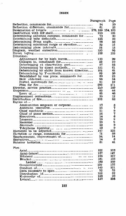
INDEX
Paragraph Page Deflection, commands for__________________________ 54 20 Deflection difference, commands for_______________ 61 23 Designation of targets ___________________________ 178, 189 154, 163 Destruction with HE shelL------------------------ 210 181 Determining adjusted compass, commands for______ 73 30 Determining base deflection_______________________ 125 88 Determining firing angle----------------·---------- 98 56 Determining minimum range or elevation__________ 32 13 Determining piece intervals_______________________ 31 13 Diagram, weather correction______________________ 130 95 Direct laying------------------------------------- 156 133 Direction:
Adjustment for by high bursts________________ 133 99 Changes in, commands for____________________ 52 20 Determining at observation post______________ 97 55 Determining by direct methods________________ 101 61 Determining by shifts from known direction___ 101 61 Determining by ¥-azimuth____________________ 99 59 Established by one piece, commands for_______ 60 23 How obtained________________________________ 96 54 Initial, commands· for _______ ,__________________ 51 19 Plan for fire__________________________________ 200 171
Director, service practice__________________________ 2:00 189 Dispersmn ____ ------- ____ --- __________ ------- ___ -- 83 46
Laws oL------------------------------------- 85 48 Displacement corrections__________________________ 30 12 Distribution of fire________________________________ 102 62 Duties of- '
Ammunition sergeant or corporaL------------- 17 8 Assistant executive___________________________ 15 7 Chief mechaniC------------------------------- 21 9 Chief of piece section_________________________ 16 7 Executives------------------------------------ 14 6 Linemen_____________________________________ 19 9 ltecorder------------------------------------- 20 9 Sentinels------------------------------------- 22 9 Telephone bperator___________________________ 18 9
Elements to be adjusted__________________________ 147 123 Elevation or range, commands for_________________ 71 28 Emplacements, improvement of____________________ 34 14 Executives---------------------------------------- 14 6 Exterior ball!stics_________________________________ 81 41
Fire: Axial----------------------------------------- 152 126 Axial-lateraL ______________ -·- ________ --------- 167 147 Bilateral------------------.------------------- 168 147 Bracket______________________________________ 181 156
Ladder___________________________________ 182 159 Concentrations------------------------------- 139 102 Cbnduct of----------------------------------- 143 121 Data necessary to open________________________ 92 53 Distribution oL______________________________ 102 62 K-transfer oL________________________________ 128 90 Lateral--------------------------------------- 157 135
193
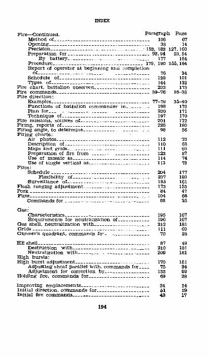
INDEX
Fire-Continued. 'Paragraph Page 67 14
127,160 53,54
154 155,164
Method oL---------------------------------'-- 106 Opening ___________________________________ ,__ 33 Preci.sion ___________________________________ 153, 183 Preparation for ____________________________ , __ 93,94
By battery ____________________________ ,__ 177 Procedure __________________________________ 179, 190 Report of operator at beginning and completion of _______________________________________ , __ Schedule oL ________________________________ _ Types oL ___________ -------------------- --~--
Fire chart, battalion observed ____________________ _ Fire commands __________________________________ _ Fire direction: Examples __________________________________ ., __
Functions of battalion commander in ______ _, __ Plan for ______________________________ .. ______ _ Technique of ________________________________ _
Fire missions, sources oL ________________________ _ Firing, reports oL _____________________________ _, __ Firing angle, to determine __________________ . ____ _, __ Firing charts:
Air photos ________________________________ ., __ Description oL _________ ------------ _________ _ ~ps and grids ____________________________ ., __ Preparation of fire from ______________________ _ Use of mosaic as _____________________________ _ Use of single vertical as ____________________ ., __
Fires: Schedule _________________________________ -•- _
Surv~~~l~~~~t~f~~=:::: =:::: :·: ==:::::: == =:::: == ~ash ranging adjustment ________________________ _
Fork---------------------------·---------------·-~e---------------------------------------------
Commands for--------------------------------
Gas:· Characteristics _______________________________ _ Requirements for neutralization oL __________ _
Gas shell, neutralization with __________________ • __ Grids ---------- ______________________________ -•- _ Gunner's quadrant, commands for ________________ _
HE shelL---------------------------- ________ ----_ Destruction with_------------------ ______ -• __ Neutralization with ____ ----- ______________ -·--
High bursts: High burst adjustment ___________________________ _
Adjusting sheaf parallel with, commands for_ __ _ Adjustment for correction by ________________ _
Holding fire, commands for _______ c ______________ _
Improving emplacements _________________ ---------Initial direction, commands for ___________________ _ Initial fire commands-----------------------------
194
76 138 144 203
39-76
77-79 198 200 197 201 225
98
112 110 111 123 114 113
204 207 185 173 84
104 66
195 196 212 111 70
87 210 209
170 75
133 69
34 51 43
34 101 122 173
16-35
35-40 170 171 170 172 190
56
70 68 69 87 74 73
177 180 161 153
47 66 25
167 167 181 69 28
49 181 181
151 34 99 28
14 19 17
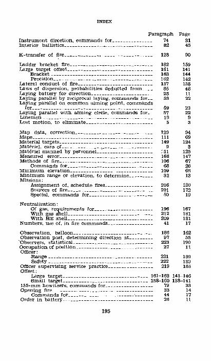
INDEX
Paragraph Page Instrument direction, commands for_______________ 74 31 In.terior ballistics-------------~-~----------------- 82 45
}(-transfer of fire_________________________________ 128 90
Ladder bracket fire_______________________________ 182 159 Large target offset________________________________ 161 141
Bracket______________________________________ 163 144 Precision _________ --- ____ --___________________ 162 142
Lateral conduct of fire____________________________ 157 135 Laws of dispersion, probabilities deducted from____ 85 48 Laying battery for direction_______________________ 28 11 Laying parallel by reciprocal laying, commands for__ 58 22 Laying parallel on common aiming point, commands
for_____________________________________________ 59 23 Laying parallel with aiming circle, commands for__ 57 22 Linemen_________________________________________ 19 9 Lost motion, to eliminate_________________________ 5 3
Map data, correction_____________________________ 129 94 Maps_____________________________________________ 111 69 Material targets___________________________________ 149 124 Materiel, care oL--------------.------------------- 9 3 Materiel manned by personneL____________________ 151 125 Measured error___________________________________ 166 147 Methods of fire----------------------------------- 106 67
Commands for________________________________ 68 26 Minimum elevation_______________________________ 109 68 Minimum range or elevation, to determine_________ 32 13 Missions:
Assignment of, schedule fires__________________ 206 180 Sources of fire________________________________ 201 172 Special, commands for________________________ 50 19
Neutralization: Of gas, requirements for______________________ 196 167 With gas shelL_______________________________ 212 181 With HE shell-------------------------------- 209 181
Numbers, use of, in fire commands_________________ 41 17
Observation, balloon ____ ---------------- ______ ---- 186 Observation post, determining direction at_________ 97
'observers, statistical _______ ---------- ______ ------_ 223 Occupation of position_____________________________ 27 Officer:
Range--------------------------------------- 221 Safety __________ ------ ___________________ -·-- _ 222
Officer supervising service practice_________________ 219 Offset:
Large target-------------------------------- 161-163 Small target ________________________________ 158-160 155-mm howitzers, commands for__________________ 79 Opening fire______________________________________ 33
Commands for _______________________ , __ ._______ 44 Order in batterY-------------------·--------------- 26
195
162 55
190 11
189 189 183
141-146 138-141
38 14 17 11
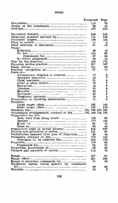
INDEX
Paragraph Orientation ____ --~------ __________ , ___________ -~--_ 118 Origin of fire commands--------~------------~--- 40 Overlays__________________________________________ 137
Page 75 16
100
Percussion bracket----------------------------~--·- 154 129 Personnel, materiel manned bY-------------------- 151 125 Personnel targets-----------------------------~--- 150 124 Piece, to unload-------------------------------~--- 11 5 Piece intervals, to determine---------------------- 31 13 Pieces:
Referring_____________________________________ 29 12 To fire-----------------------------------~--- 105 67
Commands for------------------------•--- 67 26 To follow commands----------------------•--- 48 18
Plan for fire direction-------------------------+--- 200 171 Planning service practice----------------------·--- 217 187 Plans, surveY------------------------------------- 121 85 Position, occupation oL-----------------------•--- 27 11 Posts of-
Ammunition sergeant. or corporaL _________ .___ 17 8 Assistant executive------------------------·--- 15 7 Chief mechanic_______________________________ 21 9 Chief of piece section_________________________ 16 7 Executives------------------------------------ 14 6 Linemen------------------------------------- 19 9 Recorder------------------------------------- 20 9 Sentinels_____________________________________ 22 9 Telephone operator___________________________ 18 9
Precautions in handling ammunition______________ 12 6 Precision:
Large target offset____________________________ 162 142 Small target offset____________________________ 159 138
Precision fire-------~--------------------------- 153, 183 127, 160 Preliminary arrangements, conduct of fire _______ 176, 188 154, 163 Preparation for fire:
Basic data from firing charts__________________ 126 89 Battery-----·---------------------------------- 177 154 Kinds oL ________________________________ ·____ 94 54 Steps in________________________________________ 93 53
Preparatory steps in service practice________________ 218 187 Priority and procedure of surveY-------------------- 122 87 Probabilities deduced from laws of dispersion______ 85 48 Procedure, conduct of fire_________________________ 179 155
Principles of, in observed fire__________________ 202 173 Project!le _______ --------------------- _ ------------- 104 66
Commands for-------------------------------- 64 25 Projectiles, penetration oL________________________ 86 49 Purpose and necessity of survey___________________ 115 74
Range __________ --·- _________ ------ ________ -------_ Range officer-------------------------------------Range or elevation, commands for ________________ _ Reciprocal laying, laying parallel by, commands
for.------------·-----------_----------- ________ _ Recorder _ -------··------------------- ____________ _
196
107 221 71
58 20
67 189
28
22 9
INDEX
Paragraph Page Recording an adjustment_________________________ 184 161 Records__________________________________________ 37 15 Referring pieces---------------------------------- 29 12 Registration ____________________________________ 145, 174 122, 153 Reliefs------------------------------------------- 36 15 Repetition of fire commands---------------------- 42 17 Replacement of casualties_________________________ 23 10 Report by operator of beginning and completion of
fire____________________________________________ 76 34 Reports of firing__________________________________ 225 190 Resuming fire, commands for_____________________ 46 18 Resupply of ammunition__________________________ 24 10 Rolling barrage___________________________________ 141 115
Safety officer_ ____________________________________ . 222 189 Schedule fires------------------------------------- 204 177
ABsignment___________________________________ 136 100 Commands for________________________________ 72 29 Definition------------------------------------ 134 99 Flexibility_------- __ --_----------------- __ ---_ 207 180 Types________________________________________ 135 99
Schedule of fire---------------------------------- 138 101 Scope of manuaL________________________________ 1 1 Sensing__________________________________________ 146 123 Sequence of fire commands_______________________ 49 19 Sentinels _______ -----_____________________________ 22 9 Sergeant, ammunition____________________________ 17 8 Service practice :
Definition------------------------------------ 216 187 Director______________________________________ 220 189 Officer supervising____________________________ 219 188 Planning-----------~------------------------- 217 187 Preparatory steps In__________________________ 218 187
75-mm guns with French sightll, commands for_____ 78 38 75-mm guns with panoramic sights, commands for__ 77 35 Shrapnel ____________________ c____________________ 88 50 Signals, commands for____________________________ 47 18 Site______________________________________________ 103 66 Small target offset________________________________ 158 138
Bracket______________________________________ 160 140 Precision------------------------------------- 159 138 Smoke, use of __________________________________ 191,211 165,181
Smoke screen, to build and maintain______________ 193 166 Sound ranging adjustment________________________ 172 153 Special adjustments and missions, commands for__ 50 19 Speed, definition of_______________________________ 4 2 Standing barrages-------------------------------- 140 114 Statistical observers------------------------------- 223 190 Surveillance of fires------------------------------- 185 161 Survey:
Data to be obtained-------------------------- 116 74 Operations of units___________________________ 120 81 Priority and procedure________________________ 122 87 Plans________________________________________ 121 85 Purpose and necessitY------------------------ 115 74
Suspending fire, commands for____________________ 46 18
197
INDEX
Paragraph Page 20 Target, conarnands for--------------------------,- 53
Target offset : Greater than 1,300 nails_______________________ 164 Large ---~ ______ --- _____ ------- _,_ ___ __ __ __ __ 161-163 Snaall-------------------------------------- 158-160
Targets: cnasses of __________________________________ ,_ 148
Designation oL----------------------------- 178,189 ~aterial ____________________________________ ,_ 149 Personnel ---·-- _____________________________ • _ 150
Technique of fire direction________________________ 197 Telephone operator __________ ~-------------------- 18 Tinae bracket_------------------- __ --------------- 155 Training, object oL------------------------------- 3 Transnaission of fire conanaands __________________ ._ 40 Trigononaetric naethods __ -------------------- ----•- 119 Types of adjustnaent, with air observer_ _________ +_ 180 Types of fire-----------------------------------+- 144 Types of schedul~ fires___________________________ 135
Unifornaity in giving co=ands-----------------+- 7 Units, survey operations oL---------------------~- 120 Units of announcenaent------------------------+- 108 Units of naeasuring_______________________________ 91 Unloading a piece------------------------------+- !1 Use of naosaic as firing chart--------------------+- 114 Use of single vertical as firing chart_______________ 113 Use of snaoke----------------------------------- 191,211
146 141-146 138-141
123 154, 163
124 124 170
9 131
2 16 79
155 122 99
3 81 68 53
5 74 73
165,181
VE transfer-------------------------------------+- 131 96 Visibility chart___________________________________ 214 185
Weather-correction diagrana_______________________ 130 95 Weather corrections-----------------------------+- 132 98
Y -azinau th: Co=ands for________________________________ 55 20 Deternalning direction by_____________________ 99 59
0
198