Embed Size (px)
Citation preview
GL-7.16
PROJECT INFORMATION APPROVAL STAMPProject: q Approved
Address: q Approved as noted
Contractor: q Not approved
Engineer: Remarks:
Submittal Date:
Notes 1:
Notes 2:
COUPLINGS
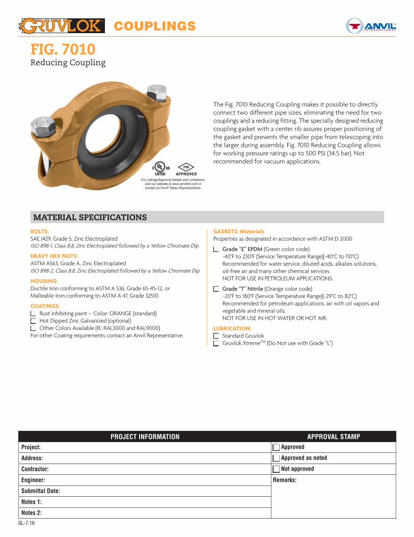
FIG. 7010Reducing Coupling
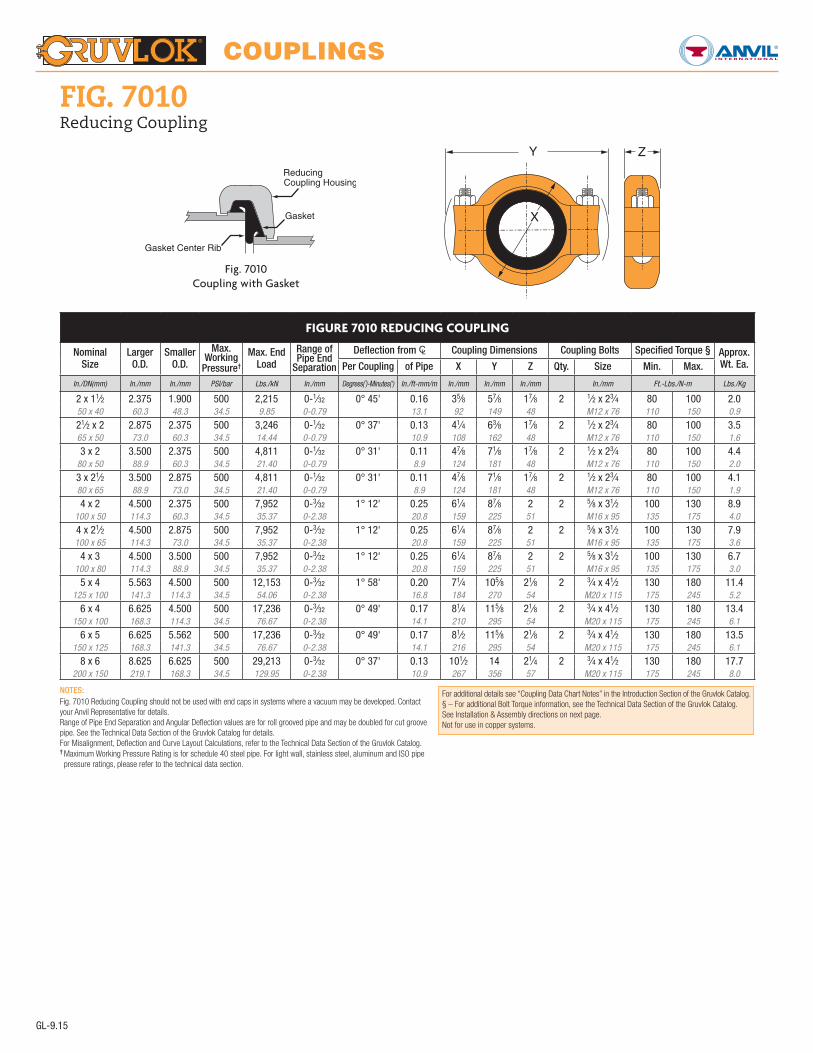
The Fig. 7010 Reducing Coupling makes it possible to directly connect two different pipe sizes, eliminating the need for two couplings and a reducing fitting. The specially designed reducing coupling gasket with a center rib assures proper positioning of the gasket and prevents the smaller pipe from telescoping into the larger during assembly. Fig. 7010 Reducing Coupling allows for working pressure ratings up to 500 PSI (34.5 bar). Not recommended for vacuum applications.
MATERIAL SPECIFICATIONS
BOLTS:SAE J429, Grade 5, Zinc ElectroplatedISO 898-1, Class 8.8, Zinc Electroplated followed by a Yellow Chromate Dip
HEAVY HEX NUTS:ASTM A563, Grade A, Zinc ElectroplatedISO 898-2, Class 8.8, Zinc Electroplated followed by a Yellow Chromate Dip
HOUSING:Ductile Iron conforming to ASTM A 536, Grade 65-45-12, orMalleable Iron conforming to ASTM A 47, Grade 32510.
COATINGS:q Rust inhibiting paint – Color: ORANGE (standard)q Hot Dipped Zinc Galvanized (optional)q Other Colors Available (IE: RAL3000 and RAL9000)For other Coating requirements contact an Anvil Representative.
GASKETS: MaterialsProperties as designated in accordance with ASTM D 2000
q Grade “E” EPDM (Green color code) -40°F to 230°F (Service Temperature Range)(-40°C to 110°C) Recommended for water service, diluted acids, alkalies solutions, oil-free air and many other chemical services. NOT FOR USE IN PETROLEUM APPLICATIONS.
q Grade “T” Nitrile (Orange color code) -20°F to 180°F (Service Temperature Range)(-29°C to 82°C) Recommended for petroleum applications. air with oil vapors and vegetable and mineral oils. NOT FOR USE IN HOT WATER OR HOT AIR.
LUBRICATION:q Standard Gruvlokq Gruvlok XtremeTM (Do Not use with Grade “L”)
For Listings/Approval Details and Limitations,visit our website at www.anvilintl.com orcontact an Anvil® Sales Representative.
COUPLINGS
For additional details see “Coupling Data Chart Notes” in the Introduction Section of the Gruvlok Catalog.§ – For additional Bolt Torque information, see the Technical Data Section of the Gruvlok Catalog.See Installation & Assembly directions on next page.Not for use in copper systems.
GL-9.15
FIG. 7010Reducing Coupling
FIGURE 7010 REDUCING COUPLING
Nominal Size
Larger O.D.
Smaller O.D.
Max. Working
Pressure†
Max. End Load
Range of Pipe End
Separation
Deflection from CL Coupling Dimensions Coupling Bolts Specified Torque § Approx. Wt. Ea.Per Coupling of Pipe X Y Z Qty. Size Min. Max.
In./DN(mm) In./mm In./mm PSI/bar Lbs./kN In./mm Degrees(˚)-Minutes(') In./ft-mm/m In./mm In./mm In./mm In./mm Ft.-Lbs./N-m Lbs./Kg
2 x 11⁄2 2.375 1.900 500 2,215 0-1⁄32 0° 45' 0.16 35⁄8 57⁄8 17⁄8 2 1⁄2 x 23⁄4 80 100 2.050 x 40 60.3 48.3 34.5 9.85 0-0.79 13.1 92 149 48 M12 x 76 110 150 0.9
21⁄2 x 2 2.875 2.375 500 3,246 0-1⁄32 0° 37' 0.13 41⁄4 63⁄8 17⁄8 2 1⁄2 x 23⁄4 80 100 3.565 x 50 73.0 60.3 34.5 14.44 0-0.79 10.9 108 162 48 M12 x 76 110 150 1.6
3 x 2 3.500 2.375 500 4,811 0-1⁄32 0° 31' 0.11 47⁄8 71⁄8 17⁄8 2 1⁄2 x 23⁄4 80 100 4.480 x 50 88.9 60.3 34.5 21.40 0-0.79 8.9 124 181 48 M12 x 76 110 150 2.0
3 x 21⁄2 3.500 2.875 500 4,811 0-1⁄32 0° 31' 0.11 47⁄8 71⁄8 17⁄8 2 1⁄2 x 23⁄4 80 100 4.180 x 65 88.9 73.0 34.5 21.40 0-0.79 8.9 124 181 48 M12 x 76 110 150 1.9
4 x 2 4.500 2.375 500 7,952 0-3⁄32 1° 12' 0.25 61⁄4 87⁄8 2 2 5⁄8 x 31⁄2 100 130 8.9100 x 50 114.3 60.3 34.5 35.37 0-2.38 20.8 159 225 51 M16 x 95 135 175 4.0
4 x 21⁄2 4.500 2.875 500 7,952 0-3⁄32 1° 12' 0.25 61⁄4 87⁄8 2 2 5⁄8 x 31⁄2 100 130 7.9100 x 65 114.3 73.0 34.5 35.37 0-2.38 20.8 159 225 51 M16 x 95 135 175 3.6
4 x 3 4.500 3.500 500 7,952 0-3⁄32 1° 12' 0.25 61⁄4 87⁄8 2 2 5⁄8 x 31⁄2 100 130 6.7100 x 80 114.3 88.9 34.5 35.37 0-2.38 20.8 159 225 51 M16 x 95 135 175 3.0
5 x 4 5.563 4.500 500 12,153 0-3⁄32 1° 58' 0.20 71⁄4 105⁄8 21⁄8 2 3⁄4 x 41⁄2 130 180 11.4125 x 100 141.3 114.3 34.5 54.06 0-2.38 16.8 184 270 54 M20 x 115 175 245 5.2
6 x 4 6.625 4.500 500 17,236 0-3⁄32 0° 49' 0.17 81⁄4 115⁄8 21⁄8 2 3⁄4 x 41⁄2 130 180 13.4150 x 100 168.3 114.3 34.5 76.67 0-2.38 14.1 210 295 54 M20 x 115 175 245 6.1
6 x 5 6.625 5.562 500 17,236 0-3⁄32 0° 49' 0.17 81⁄2 115⁄8 21⁄8 2 3⁄4 x 41⁄2 130 180 13.5150 x 125 168.3 141.3 34.5 76.67 0-2.38 14.1 216 295 54 M20 x 115 175 245 6.1
8 x 6 8.625 6.625 500 29,213 0-3⁄32 0° 37' 0.13 101⁄2 14 21⁄4 2 3⁄4 x 41⁄2 130 180 17.7200 x 150 219.1 168.3 34.5 129.95 0-2.38 10.9 267 356 57 M20 x 115 175 245 8.0
Fig. 7010Coupling with Gasket
NOTES:Fig. 7010 Reducing Coupling should not be used with end caps in systems where a vacuum may be developed. Contact your Anvil Representative for details.Range of Pipe End Separation and Angular Deflection values are for roll grooved pipe and may be doubled for cut groovepipe. See the Technical Data Section of the Gruvlok Catalog for details.For Misalignment, Deflection and Curve Layout Calculations, refer to the Technical Data Section of the Gruvlok Catalog.† Maximum Working Pressure Rating is for schedule 40 steel pipe. For light wall, stainless steel, aluminum and ISO pipe pressure ratings, please refer to the technical data section.
COUPLINGS
GL-3.14
FIG. 7010Reducing Coupling
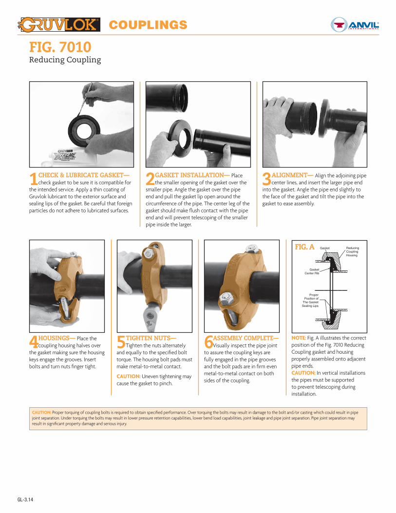
1CHECK & LUBRICATE GASKET— check gasket to be sure it is compatible for
the intended service. Apply a thin coating of Gruvlok lubricant to the exterior surface and sealing lips of the gasket. Be careful that foreign particles do not adhere to lubricated surfaces.
2 GASKET INSTALLATION— Place the smaller opening of the gasket over the
smaller pipe. Angle the gasket over the pipe end and pull the gasket lip open around the circumference of the pipe. The center leg of the gasket should make flush contact with the pipe end and will prevent telescoping of the smaller pipe inside the larger.
3 ALIGNMENT— Align the adjoining pipe center lines, and insert the larger pipe end
into the gasket. Angle the pipe end slightly to the face of the gasket and tilt the pipe into the gasket to ease assembly.
CAUTION: Proper torquing of coupling bolts is required to obtain specified performance. Over torquing the bolts may result in damage to the bolt and/or casting which could result in pipe joint separation. Under torquing the bolts may result in lower pressure retention capabilities, lower bend load capabilities, joint leakage and pipe joint separation. Pipe joint separation may result in significant property damage and serious injury.
4 HOUSINGS— Place the coupling housing halves over
the gasket making sure the housing keys engage the grooves. Insert bolts and turn nuts finger tight.
5 TIGHTEN NUTS— Tighten the nuts alternately
and equally to the specified bolt torque. The housing bolt pads must make metal-to-metal contact.
CAUTION: Uneven tightening may cause the gasket to pinch.
6 ASSEMBLY COMPLETE— Visually inspect the pipe joint
to assure the coupling keys are fully engaged in the pipe grooves and the bolt pads are in firm even metal-to-metal contact on both sides of the coupling.
NOTE: Fig. A illustrates the correctposition of the Fig. 7010 ReducingCoupling gasket and housing properly assembled onto adjacent pipe ends.CAUTION: In vertical installationsthe pipes must be supported to prevent telescoping during installation.
GasketCenter Rib
ProperPosition of
The GasketSealing Lips
Gasket ReducingCouplingHousing
FIG. A