Embed Size (px)
Citation preview
FINAL DESIGN REPORT/FINAL EIS/FINAL SECTION 4(F)
EVALUATION
PIN 0054.05.103NY Route 347 Safety and Mobility Improvement
Project
Northern State Parkway to NY Route 25ATowns of Smithtown, Islip & Brookhaven
Suffolk County
May 2007
Storm Water Management andRoadway Drainage Technical Report
Volume II, Appendix F
U.S. Department of TransportationFederal Highway Administration
NEW YORK STATE DEPARTMENT OF TRANSPORTATIONELIOT SPITZER, Governor ASTRID C. GLYNN, Acting Commissioner
2
Table of Contents Executive Summary .......................................................................................................... 3
Compliance with NYSDEC SPDES GP-02-01 ............................................................ 3 Roadway Runoff and Stormwater Management ........................................................... 4 Roadway Runoff Collection and Conveyance .............................................................. 4
Water Quality...................................................................................................................... 4 Water Quantity.................................................................................................................... 6 Roadway Runoff and Stormwater Management ........................................................... 9
SPDES COMPLIANCE AREA.................................................................... 10 NON-SPDES COMPLIANCE AREA.......................................................... 10
Eliminate Existing MLBS..................................................................................... 11 Utilize Existing RB’s ............................................................................................... 12 Eliminate Discharge to Existing Pipe Systems ........................................................... 14
Roadway Runoff Collection and Conveyance System ........................................................ 19 Inlet Runoff Interception and Spacing ....................................................................... 19 Pipe Diameter ......................................................................................................... 24
Appendices A – Stormwater Quality Calculations B – Stormwater Quantity Calculations C – Eliminate Existing MLBS Calculations D – Utilize Existing RB’s Calculations E – Eliminate Discharge to Existing Pipe Systems Calculations F –Roadway Drainage Evaluation Inlet Runoff Interception and Spacing Calculations Pipe Diameter Calculations
3
Executive Summary The Route 347 Safety and Mobility Improvement Project provides roadwy improvements that
include the two additional 3.6 meter wide lanes and a 0.612 meter wide shoulder in each direction
along both sides of the road plus turning lanes at numerous intersections, and various
interchange/intersection alternatives at the Route 454/Route 347 split, Middle Country Road and
Nicolls Road, selected pavement widening of the ramps at the Northern State Parkway, and
variable widening of cross streets.
Runoff from the portion of the project between the high point east of White Oak Drive, Station
18+757, and the high point east of Southern Boulevard, Station 27+612, discharges to the
Nissequogue River and its tributaries. The Nissequogue River is designated a waterbody of the
United States. Therefore compliance with the New York State Department of Environmental
Conservation (NYSDEC) State Pollution Discharge Elimination System (SPDES) General Permit
(GP –02-01 is required for this portion of the project.
The report is divided into three sections, NYSDEC SPDES GP-02-01 Compliance, Roadway
Drainage and Stormwater Management, and Roadway Runoff Collection and Conveyance.
Compliance with NYSDEC SPDES GP-02-01
Compliance with both the water quality requirements and the water quantity requirements of
SPDES GP-02-01, was evaluated in accordance with the procedures contained in the New York
State Stormwater Management Design Manual (NYSSMDM).
Water quality compliance is achieved with the installation of a surface water quality basin, most
likely a stormwater pond or wetland pond, near three existing waterbodies, with overflow and
discharge from each water quality basin to the nearby existing waterbody.
Water quantity compliance for discharges to the Nissequogue River is achieved in accordance
with the provisions of Section 4.7 Downstream Analysis of the NYSSMDM. The increased
runoff resulting from the project is less than five percent of the total existing runoff in the stream
at the point of roadway runoff discharge to the existing watercourses. Consequently, compliance
4
with the intent of the Unified Stormwater Sizing Criteria is achieved. Therefore, stormwater
attenuation facilities are not required to address runoff rate changes.
Roadway Runoff and Stormwater Management
Roadway runoff from the portion of the project exempt from compliance with NYSDEC SPDES
GP-02-10, west of high point east of White Oak Drive and east of Southern Boulevard discharges
to either a recharge basin (RB), pipe system or multiple leaching basin system (MLBS). The
objective of the roadway runoff and stormwater management evaluation was to direct runoff to a
recharge basin and eliminate discharge to existing pipe systems and MLBS to the greatest extent
possible. Installation of the proposed 17 RB achieve this objective except for approximately 117
meters of Route 347 in the vicinity of the Route 11 intersection and approximate 697 meters of
the road east of Market Street to Route 25A.
Roadway Runoff Collection and Conveyance
The roadway runoff collection and conveyance and conveyance system was evaluated in
accordance with the requirements of Chapter 8, Highway Drainage, of the NYSDOT Highway
Design Manual (HDM). The runoff collection system evaluation identified the inlet spacing
required along each edge and the median of Route 347 and the resultant quantity of inlets
required for the project. The runoff conveyance system evaluation computed the pipe diameter
required for each pipe to convey runoff to a water quality basin, existing waterbody or recharge
basin. The evaluation also established the approximate invert elevation at each receiving facility
and potential need for use of a “bubbler “ chamber in selected cases when the invert was below
the invert of the receiving facility.
NYSDEC SPDES GP-02-01 Compliance
Compliance with the water quality and water quantity requirements of NYSDEC SPDES GP-02-
01 is described below
Water Quality
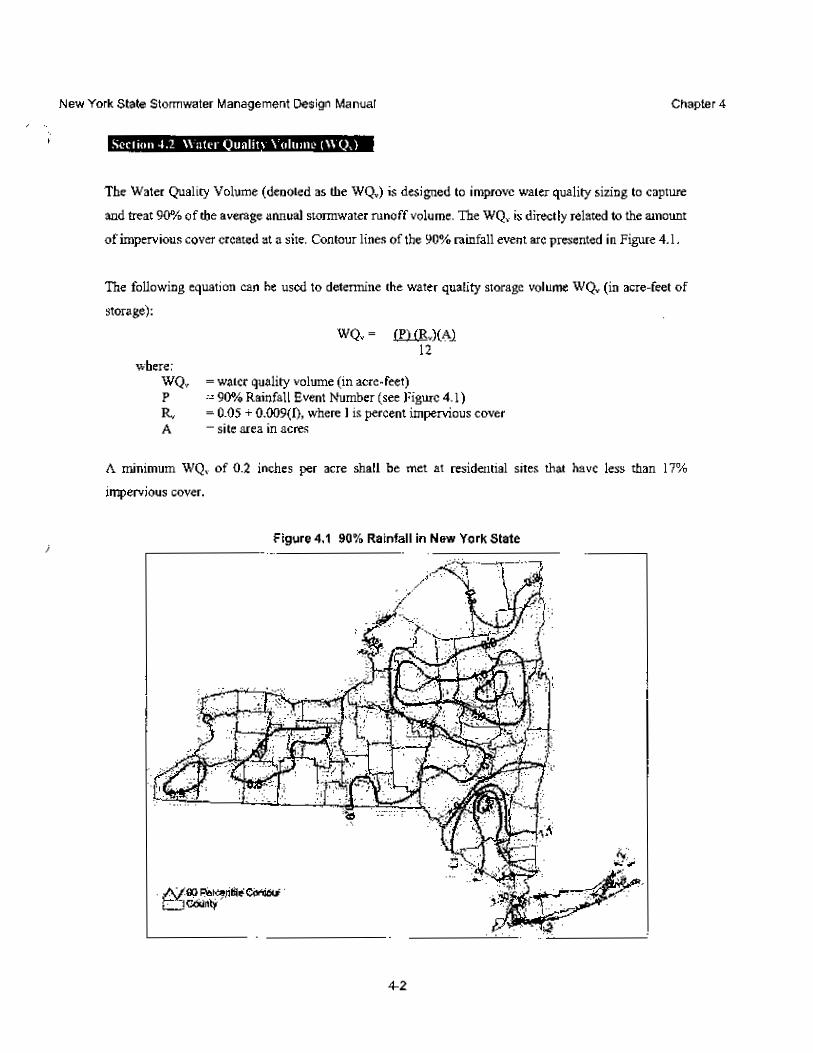
Water quality requirements are presented in Chapter 4 of the NYSSMDM. Section 4.2 includes
guidance and procedures to demonstrate compliance with the water quality requirements. The
water quality volume is directly related to the amount of impervious cover created by the project.
5
Impervious cover is defined as that portion of the project that does not have permanent vegetative
or permeable cover. Roadway pavement is considered impervious cover. The impervious cover
created by the project includes two components, the additional 3.6-meter wide lane and 0.61
meter wide additional shoulder pavement in each direction for the entire length of the project and
the left turn pavement at the intersections. Proposed sidewalk replaces existing sidewalk.
Therefore, sidewalk installation does not create impervious cover on the project. The impervious
cover created by the project includes four components:
a. two additional 3. 6 meter wide lanes and 0.61 meter wide additional shoulder
pavement in each direction yields a width of 8.42 meters.
b. additional pavement at Northern State Parkway (NSP)
c. additional pavement at cross streets
d. additional turning lane pavement at intersections.
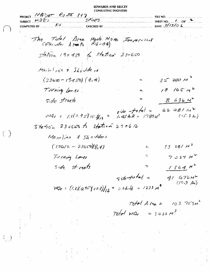
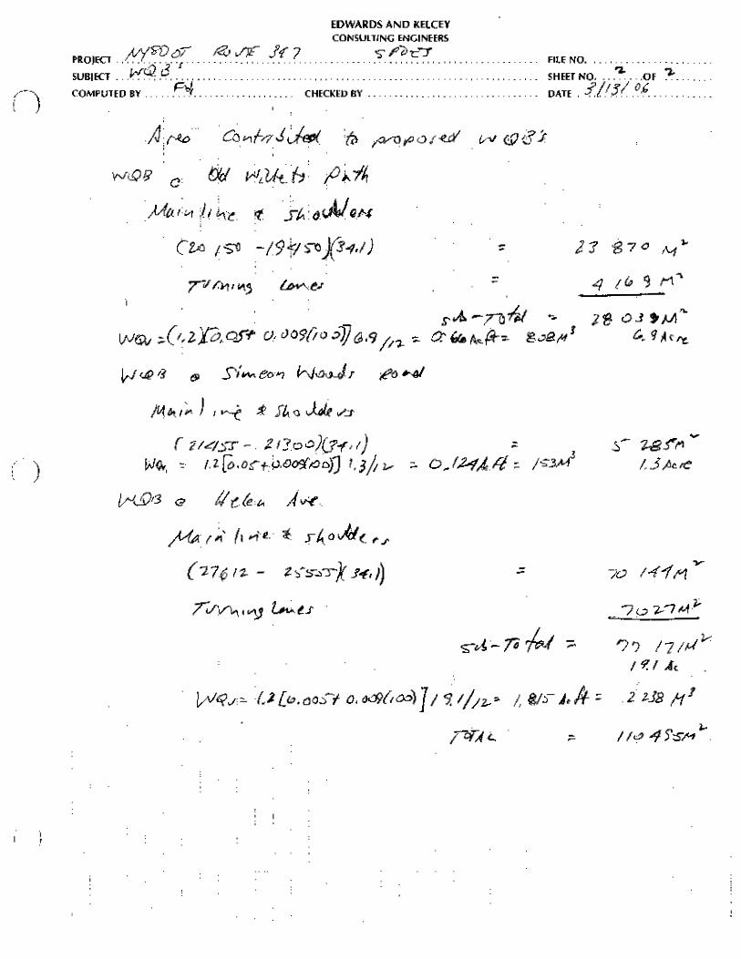
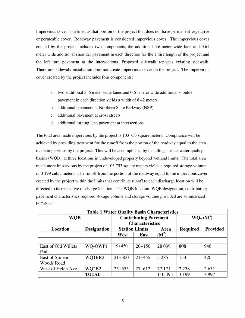
The total area made impervious by the project is 103 753 square meters. Compliance will be
achieved by providing treatment for the runoff from the portion of the roadway equal to the area
made impervious by the project. This will be accomplished by installing surface water quality
basins (WQB), at three locations in undeveloped property beyond wetland limits. The total area
made more impervious by the project of 103 753 square meters yields a required storage volume
of 3 199 cubic meters. The runoff from the portion of the roadway equal to the impervious cover
created by the project within the limits that contribute runoff to each discharge location will be
directed to its respective discharge location. The WQB location, WQB designation, contributing
pavement characteristics required storage volume and storage volume provided are summarized
in Table 1
Table 1 Water Quality Basin Characteristics WQB Contributing Pavement
Characteristics WQv (M3)
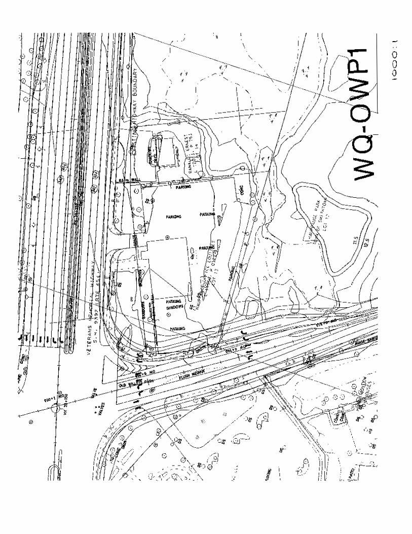
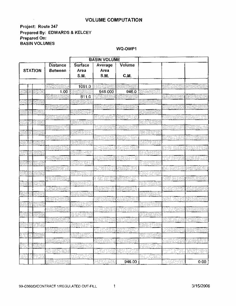
Location Designation Station Limits Area Required Provided West East (M2) East of Old Willets Path
WQ-OWP1 19+450 20+150 28 039 808 946
East of Simeon Woods Road
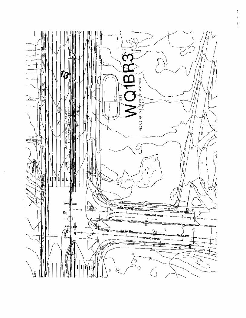
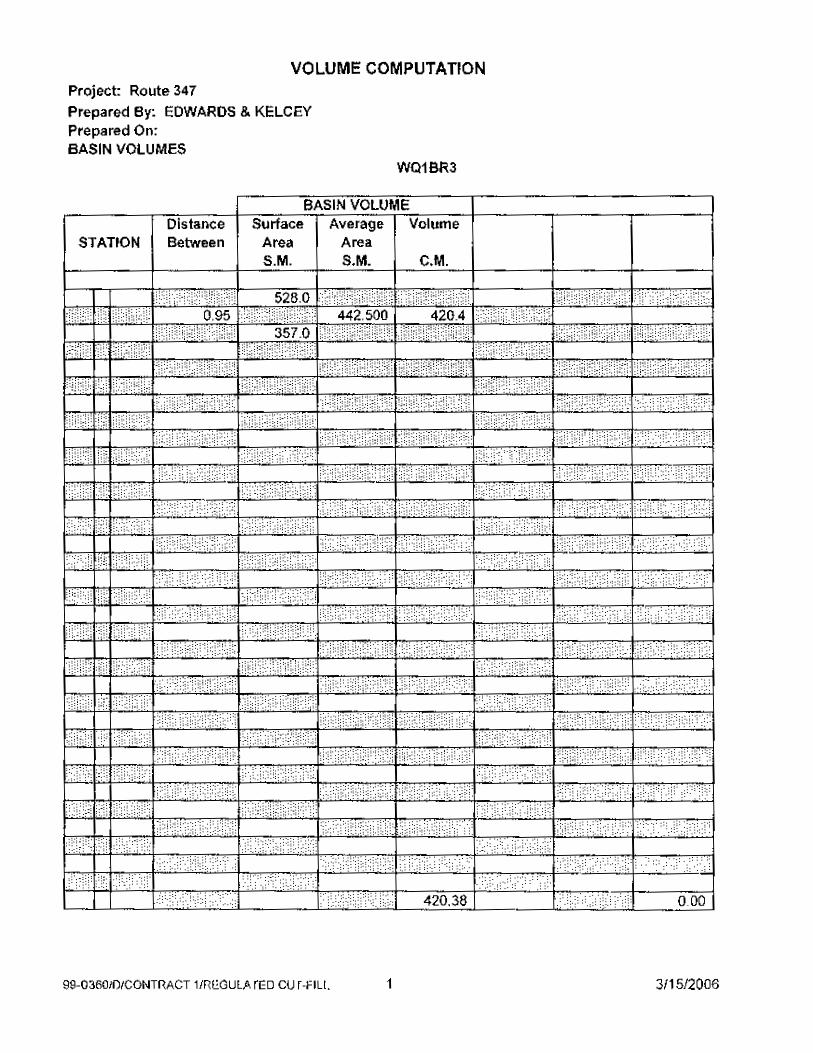
WQ1BR2 21+300 21+455 5 285 153 420
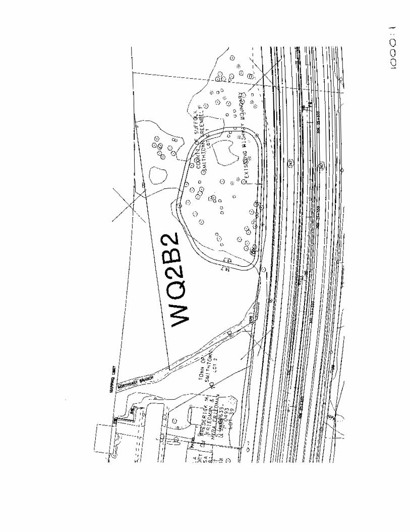
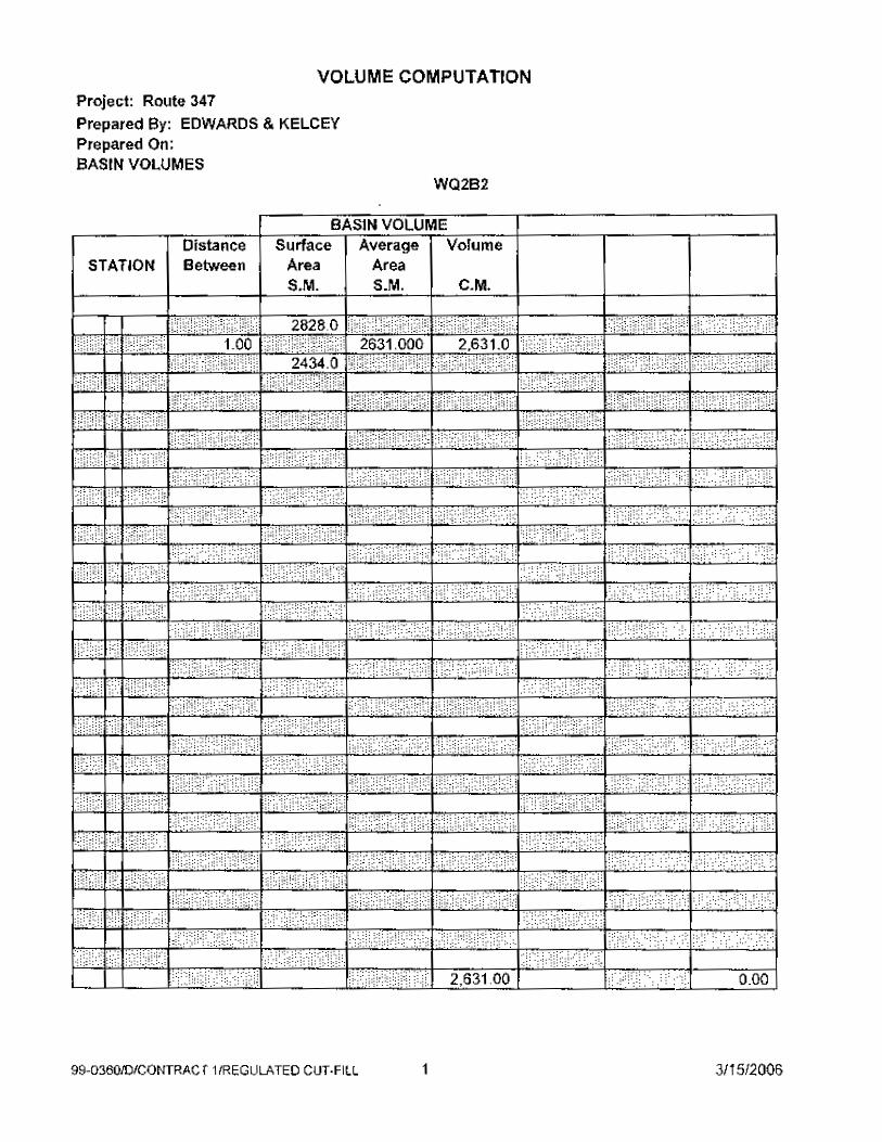
West of Helen Ave. WQ2B2 25+555 27+612 77 171 2 238 2 631 TOTAL 110 495 3 199 3 997
6
Runoff will be delivered to each proposed WQB through a closed pipe system that
collects runoff from the portion of the roadway indicated in Table 1. Runoff that exceeds
the storage volume of each proposed WQB will breach the control spillway set an
elevation below the top of the berm for the WQB, and proceed through the adjacent
wetlands to a receiving water body with a culvert crossing at Station 20+630 for WQ-
OWP1, at Station 21+230 for WQ1B2R, and at Station 25+400 for WQ2B2.
The required pipe invert is below the GWT for WQ1BR2 and WQ2B2. Installation of the pipe
with the invert elevation below the GWT, into a drainage chamber with an open grate on top that
allows runoff to overtop the chamber and enter the WQB surrounding the chamber is a reasonable
solution.
The calculations are in Appendix A.
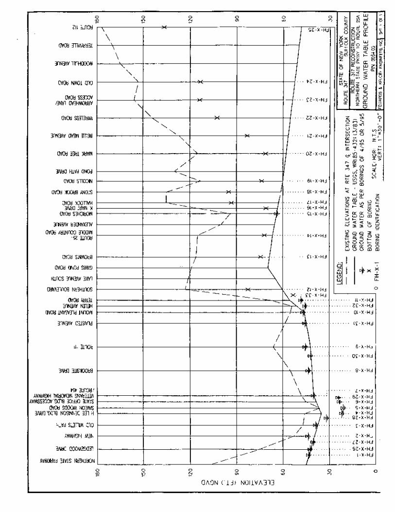
Water Quantity
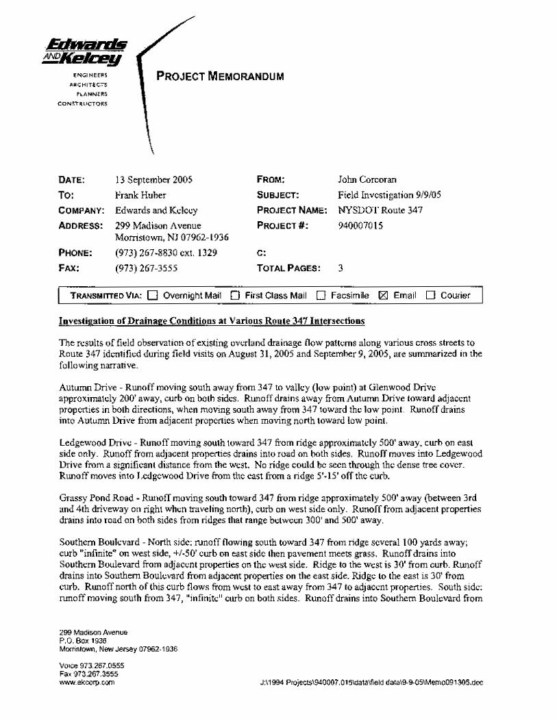
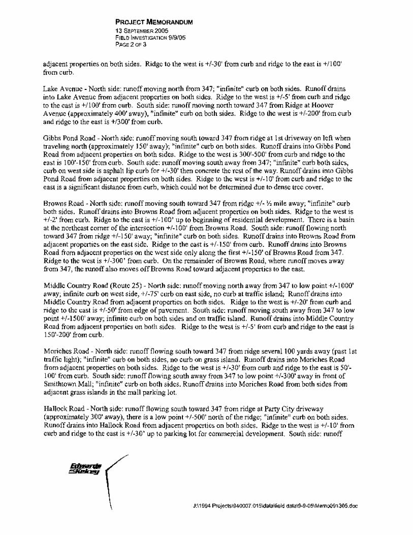
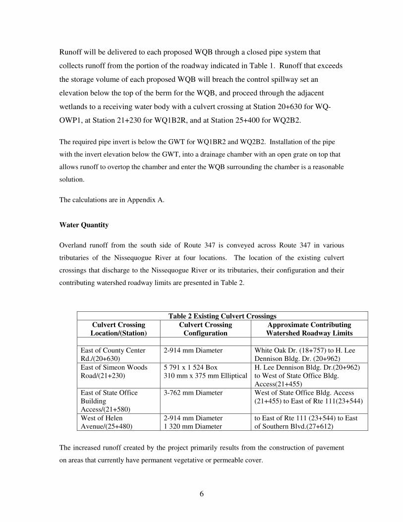
Overland runoff from the south side of Route 347 is conveyed across Route 347 in various
tributaries of the Nissequogue River at four locations. The location of the existing culvert
crossings that discharge to the Nissequogue River or its tributaries, their configuration and their
contributing watershed roadway limits are presented in Table 2.
Table 2 Existing Culvert Crossings Culvert Crossing Location/(Station)
Culvert Crossing Configuration
Approximate Contributing Watershed Roadway Limits
East of County Center Rd./(20+630)
2-914 mm Diameter
White Oak Dr. (18+757) to H. Lee Dennison Bldg. Dr. (20+962)
East of Simeon Woods Road/(21+230)
5 791 x 1 524 Box 310 mm x 375 mm Elliptical
H. Lee Dennison Bldg. Dr.(20+962) to West of State Office Bldg. Access(21+455)
East of State Office Building Access/(21+580)
3-762 mm Diameter West of State Office Bldg. Access (21+455) to East of Rte 111(23+544)
West of Helen Avenue/(25+480)
2-914 mm Diameter 1 320 mm Diameter
to East of Rte 111 (23+544) to East of Southern Blvd.(27+612)
The increased runoff created by the project primarily results from the construction of pavement
on areas that currently have permanent vegetative or permeable cover.
7
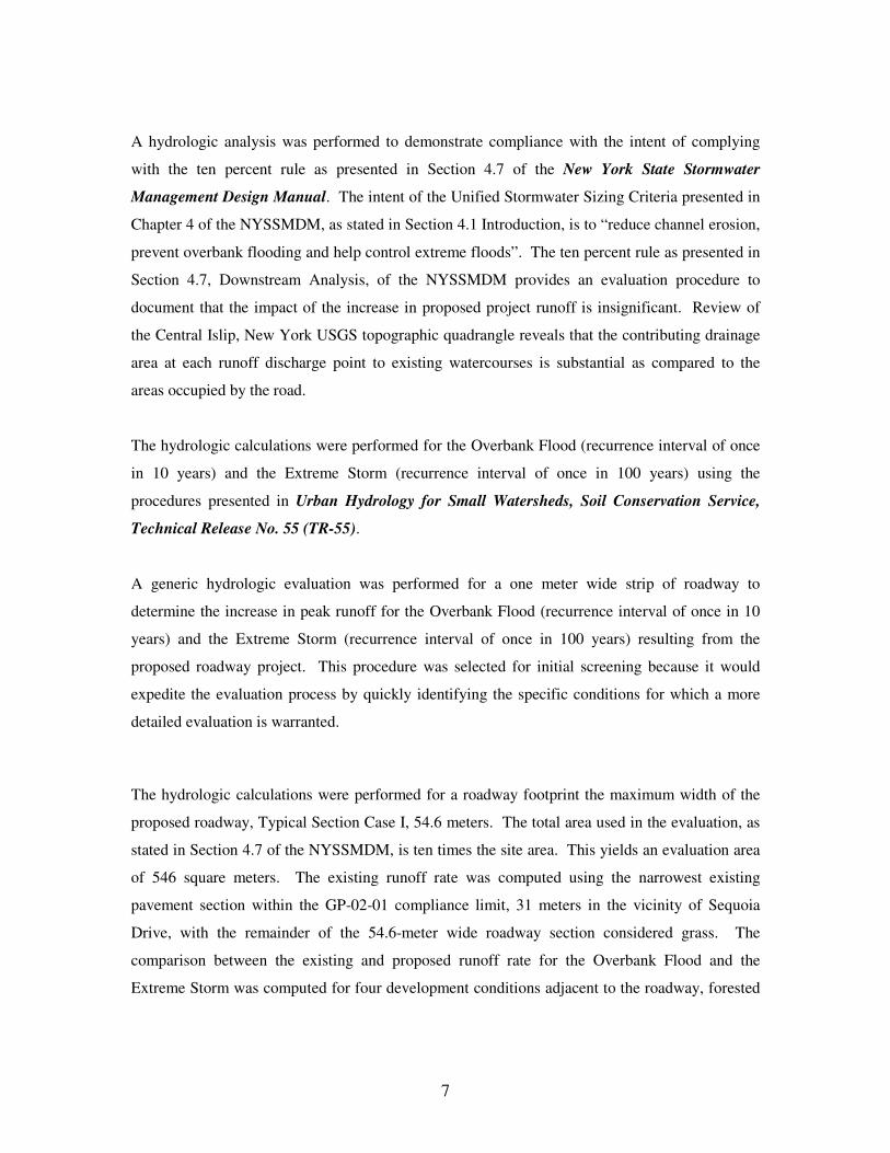
A hydrologic analysis was performed to demonstrate compliance with the intent of complying
with the ten percent rule as presented in Section 4.7 of the New York State Stormwater
Management Design Manual. The intent of the Unified Stormwater Sizing Criteria presented in
Chapter 4 of the NYSSMDM, as stated in Section 4.1 Introduction, is to “reduce channel erosion,
prevent overbank flooding and help control extreme floods”. The ten percent rule as presented in
Section 4.7, Downstream Analysis, of the NYSSMDM provides an evaluation procedure to
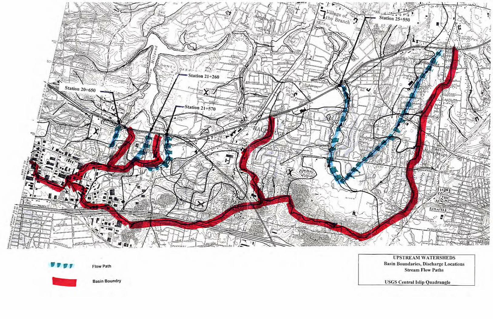
document that the impact of the increase in proposed project runoff is insignificant. Review of
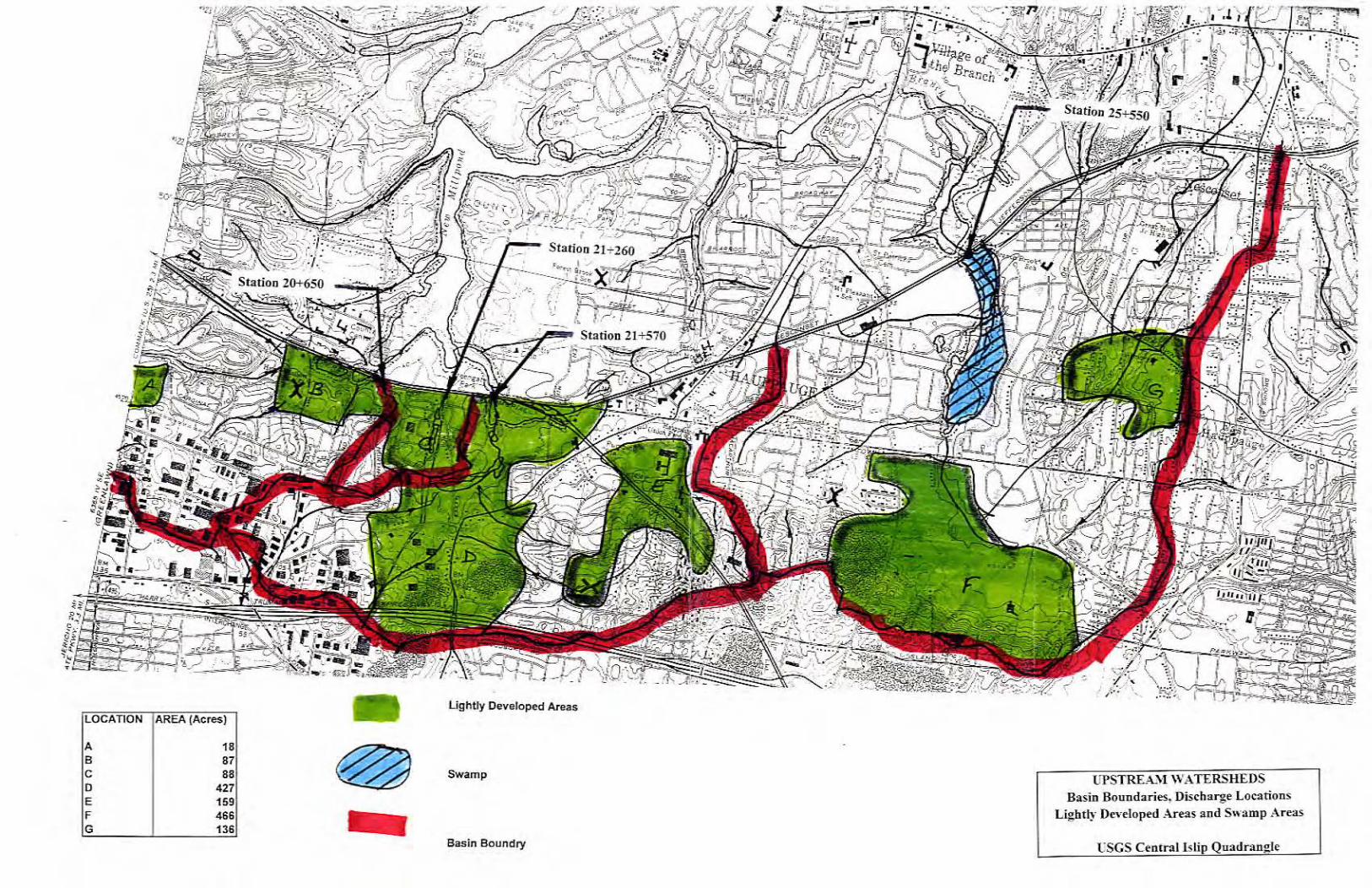
the Central Islip, New York USGS topographic quadrangle reveals that the contributing drainage
area at each runoff discharge point to existing watercourses is substantial as compared to the
areas occupied by the road.
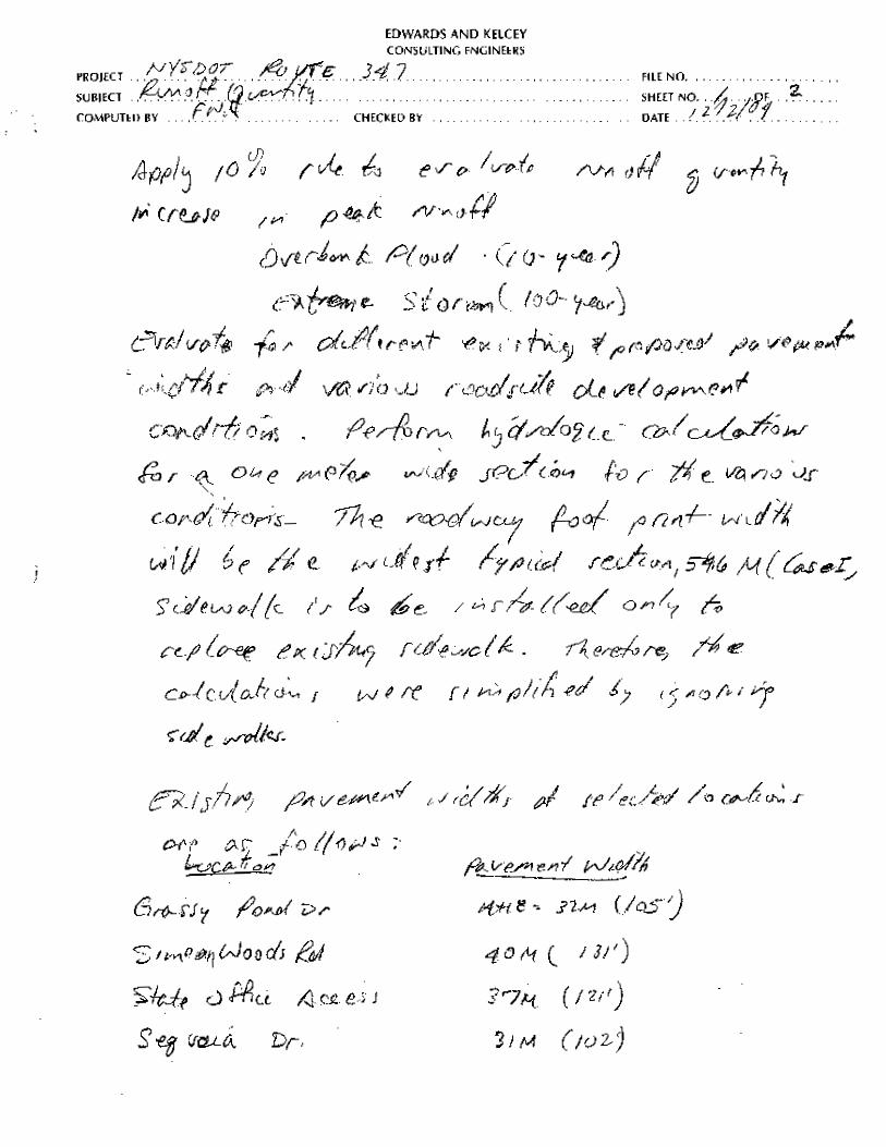
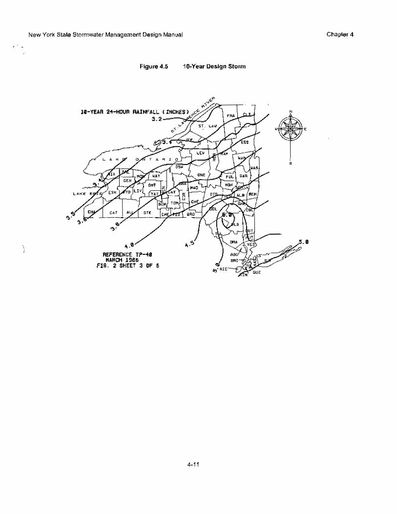
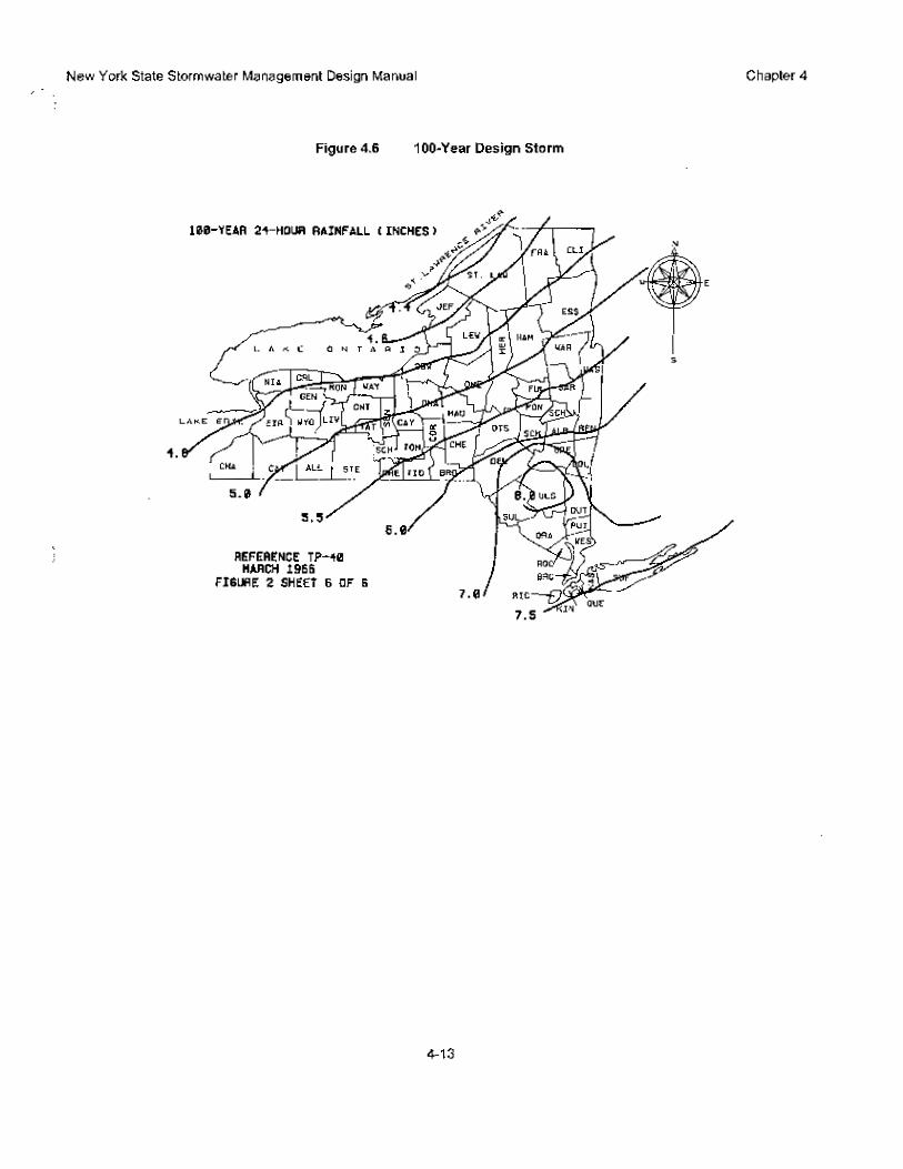
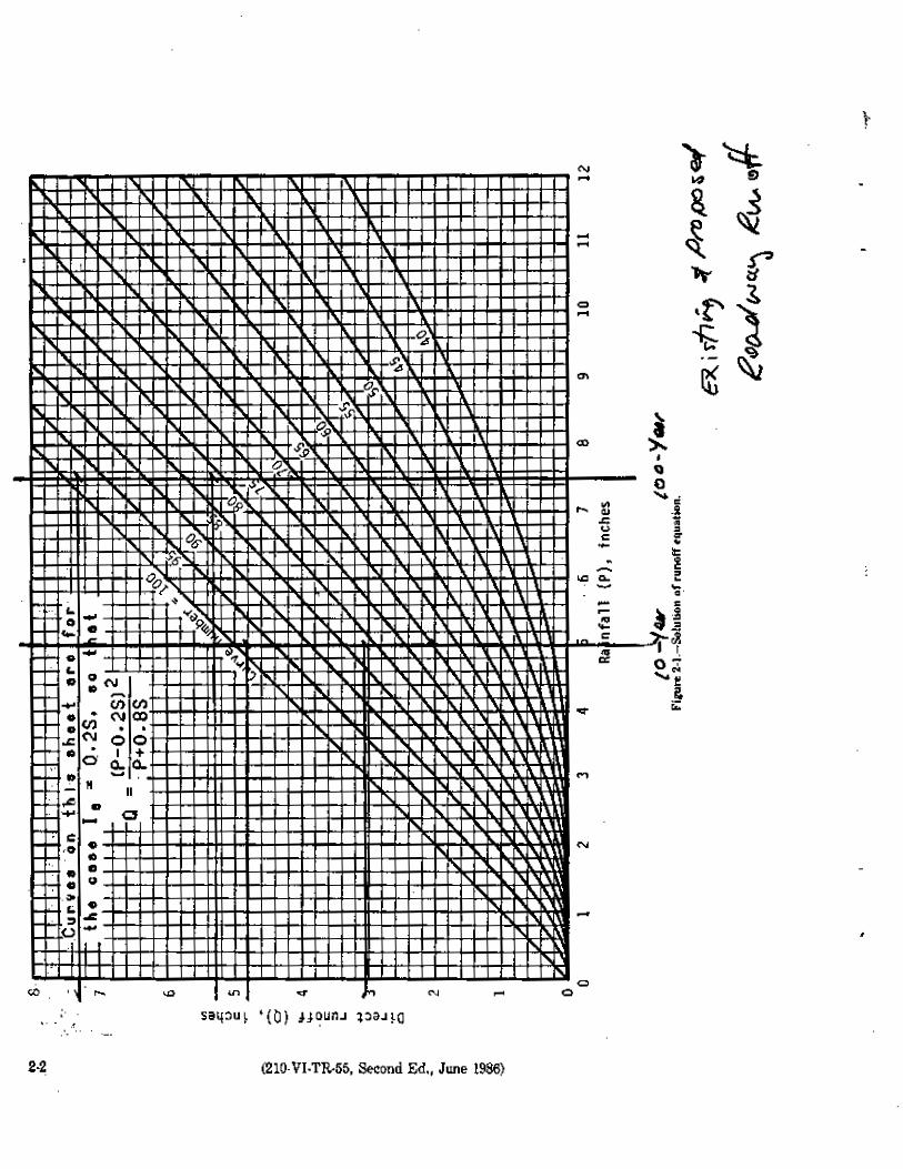
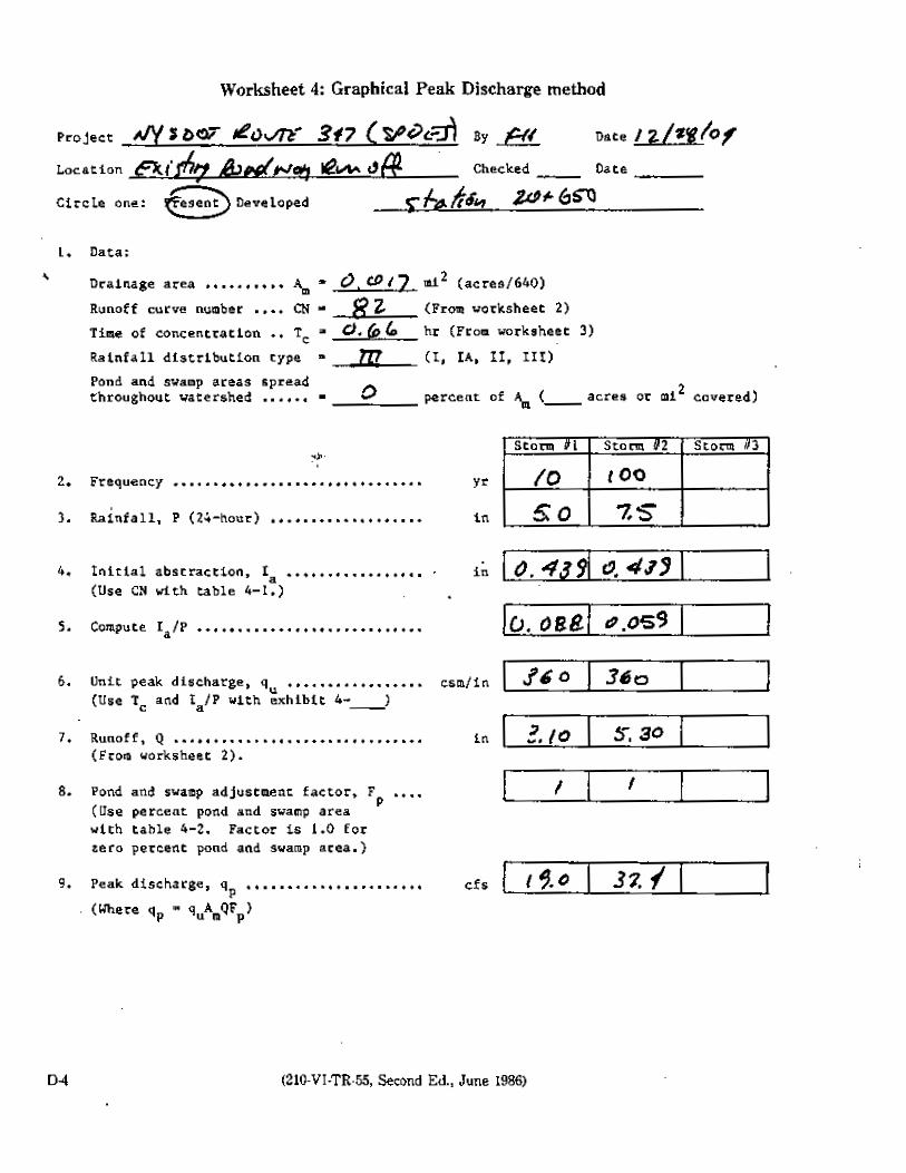
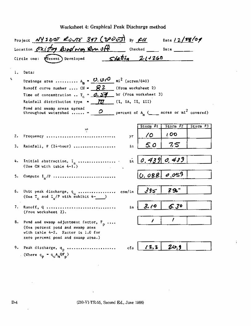
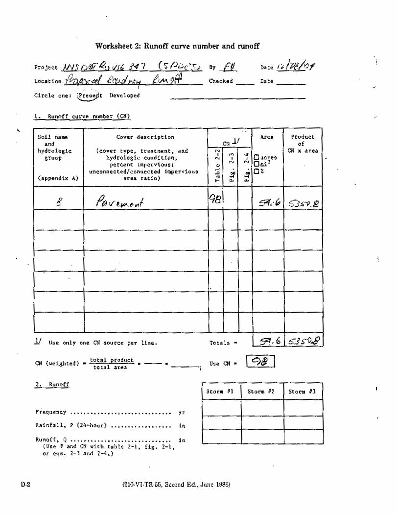
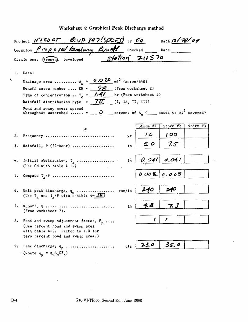
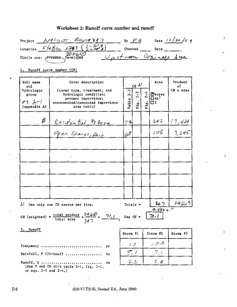
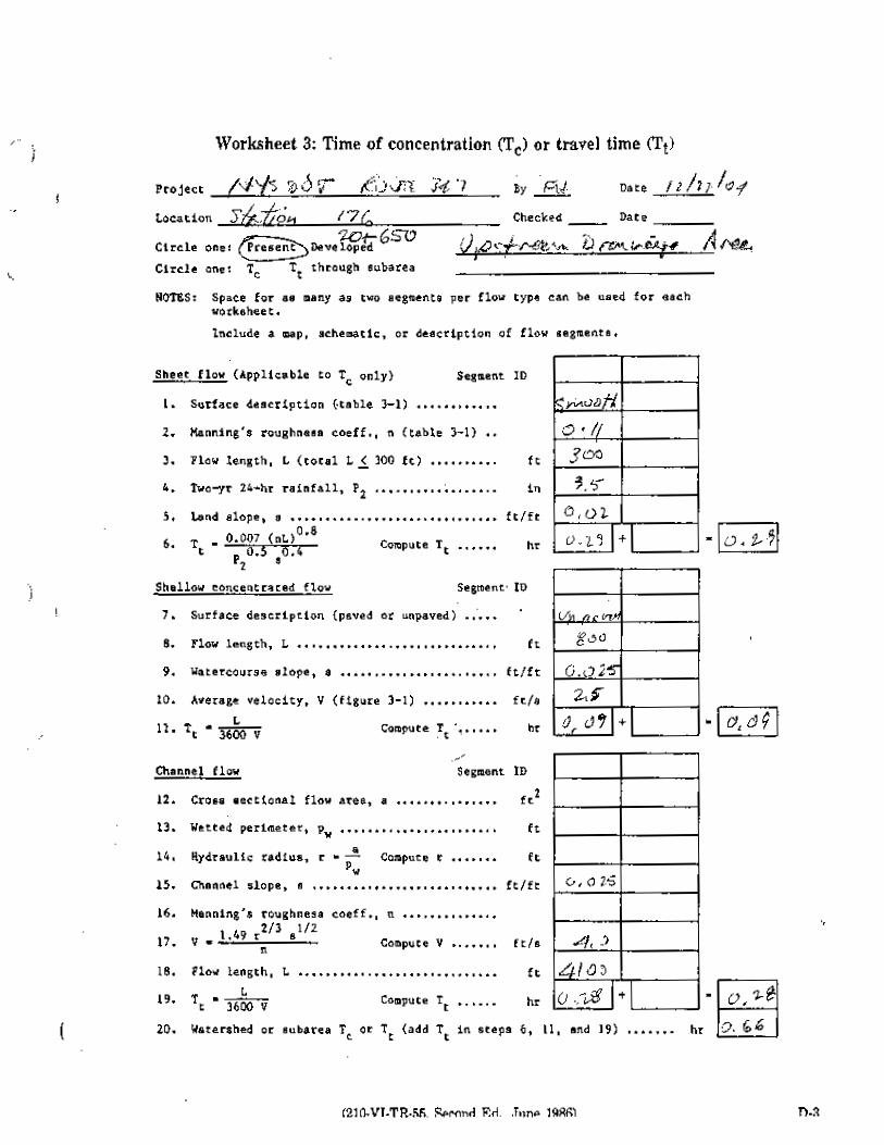
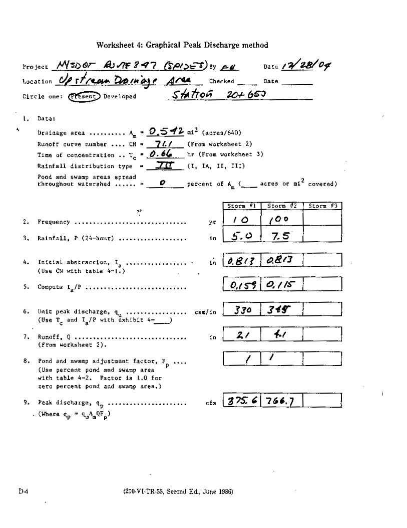
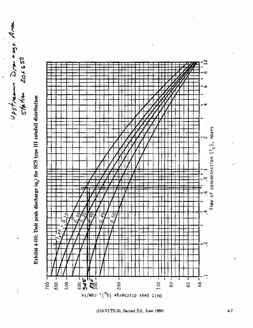
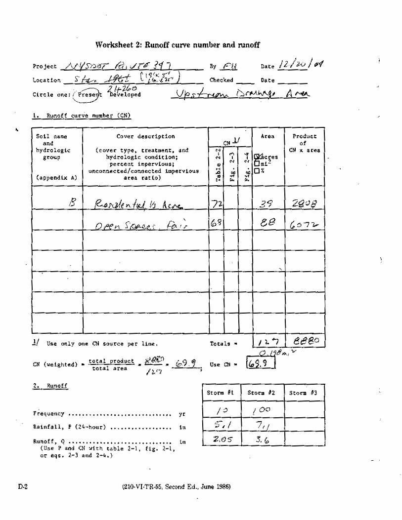
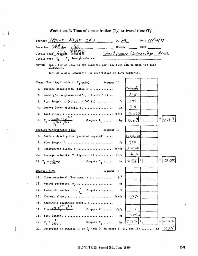
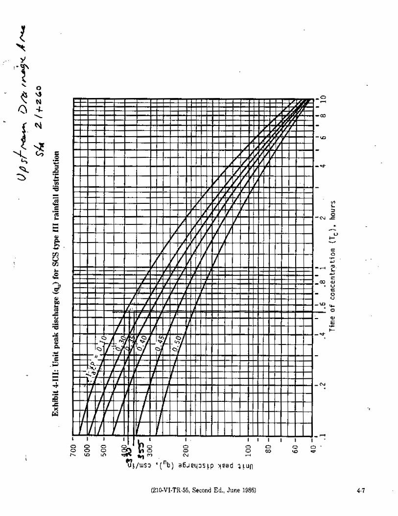
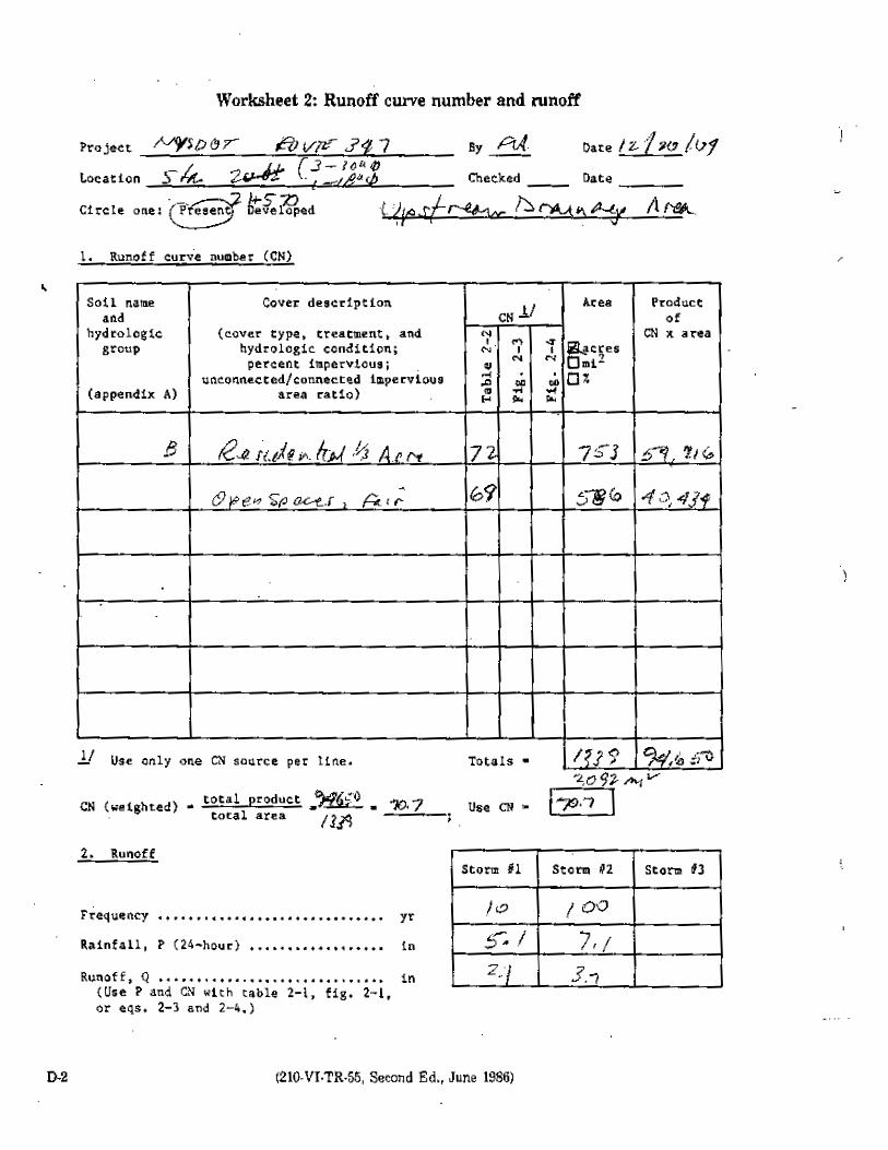
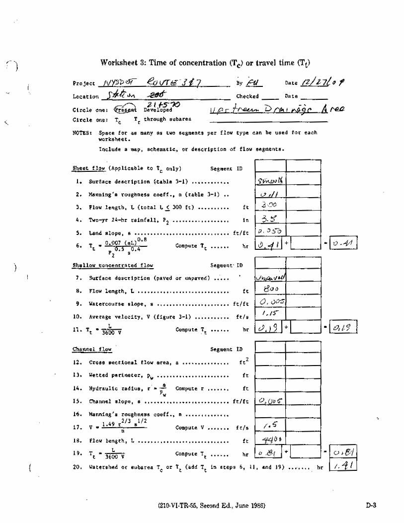
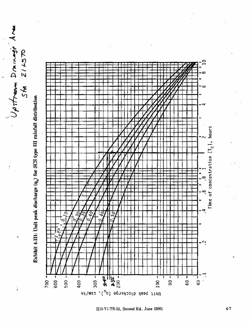
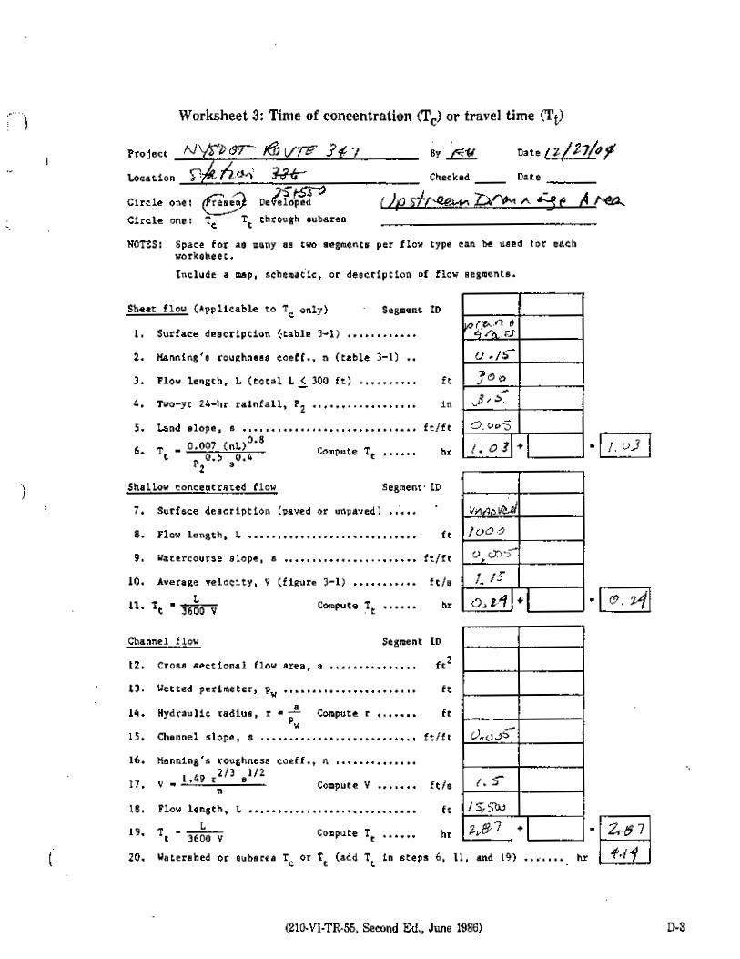
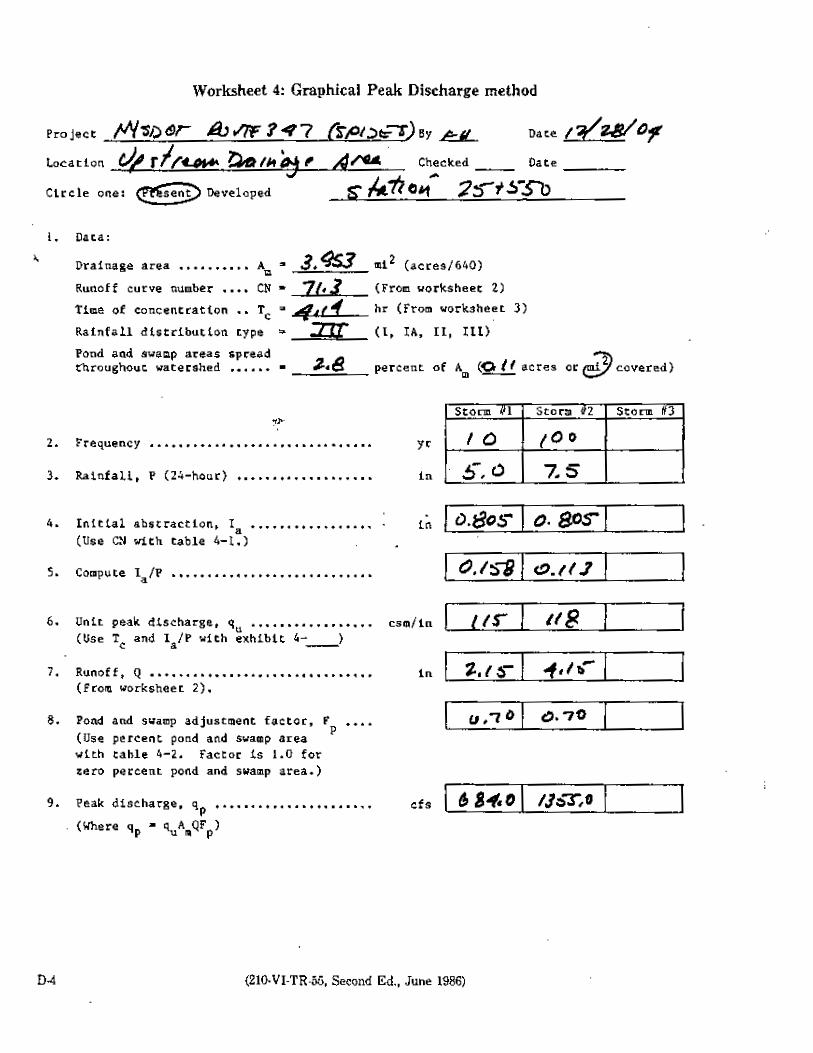
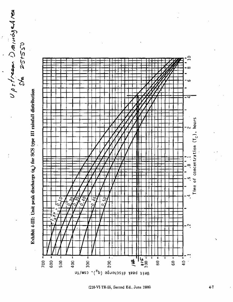
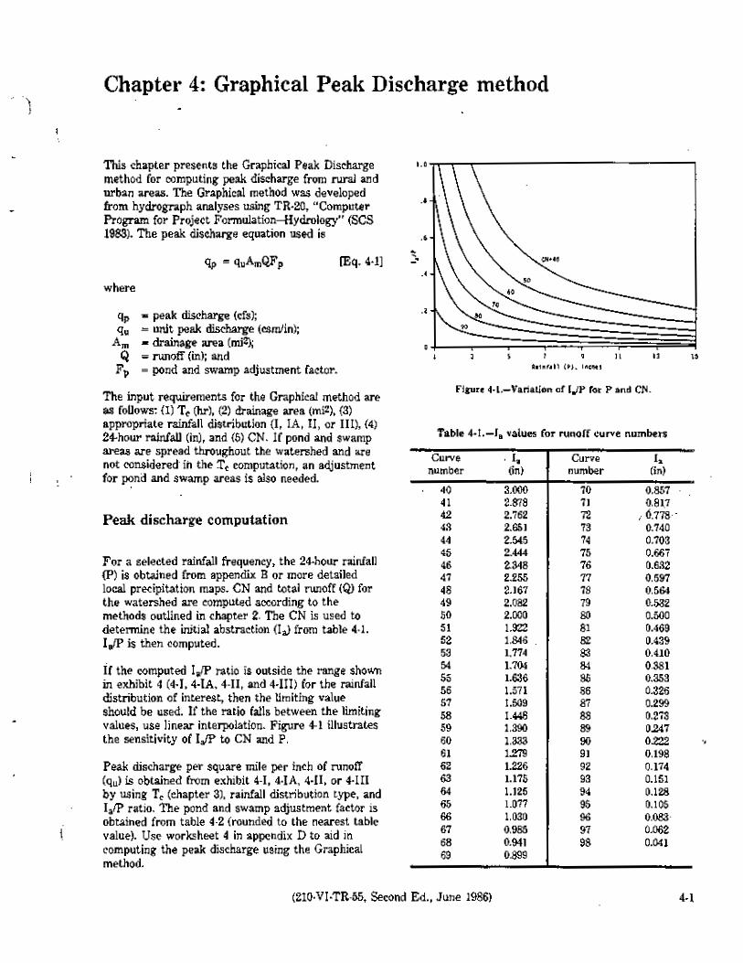
The hydrologic calculations were performed for the Overbank Flood (recurrence interval of once
in 10 years) and the Extreme Storm (recurrence interval of once in 100 years) using the
procedures presented in Urban Hydrology for Small Watersheds, Soil Conservation Service,
Technical Release No. 55 (TR-55).
A generic hydrologic evaluation was performed for a one meter wide strip of roadway to
determine the increase in peak runoff for the Overbank Flood (recurrence interval of once in 10
years) and the Extreme Storm (recurrence interval of once in 100 years) resulting from the
proposed roadway project. This procedure was selected for initial screening because it would
expedite the evaluation process by quickly identifying the specific conditions for which a more
detailed evaluation is warranted.
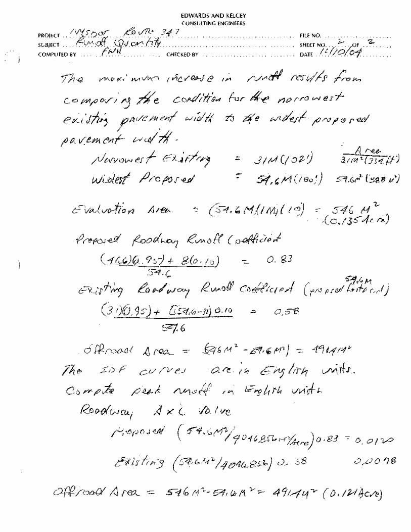
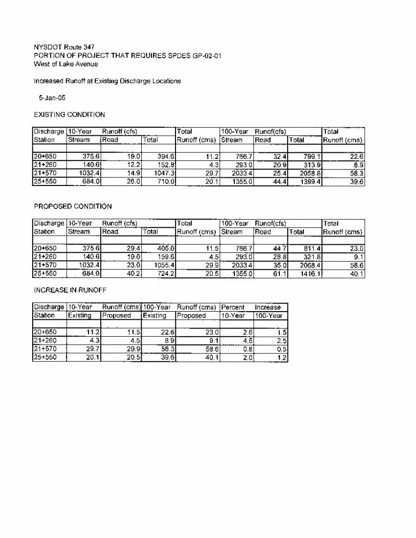
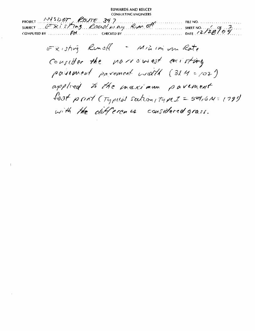
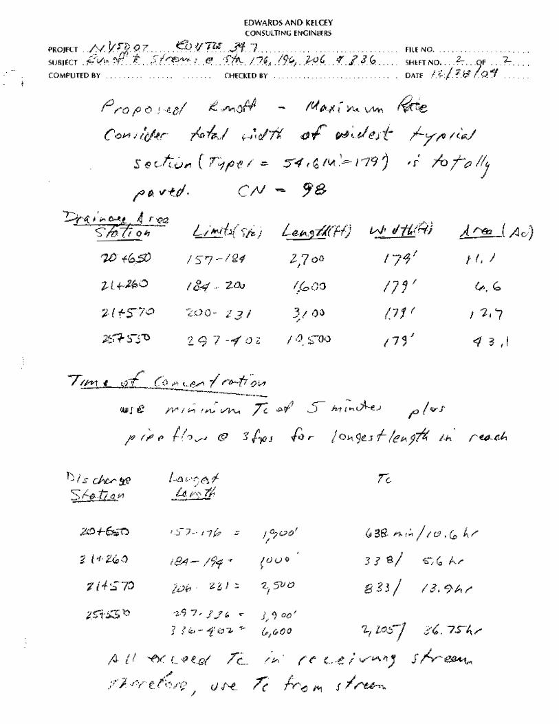
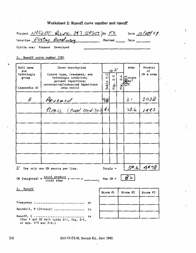
The hydrologic calculations were performed for a roadway footprint the maximum width of the
proposed roadway, Typical Section Case I, 54.6 meters. The total area used in the evaluation, as
stated in Section 4.7 of the NYSSMDM, is ten times the site area. This yields an evaluation area
of 546 square meters. The existing runoff rate was computed using the narrowest existing
pavement section within the GP-02-01 compliance limit, 31 meters in the vicinity of Sequoia
Drive, with the remainder of the 54.6-meter wide roadway section considered grass. The
comparison between the existing and proposed runoff rate for the Overbank Flood and the
Extreme Storm was computed for four development conditions adjacent to the roadway, forested

8
areas, light residential (30% impervious), moderate residential (60 % impervious) and
commercial. The resultant runoff coefficients are 0.20, 0.40, 0.65 and 0.80 respectively.
A 1.2 meter wide sidewalk is to be installed along the edge of the roadway to replace an existing
sidewalk. The calculation was performed to identify the change in runoff resulting from the
project. Therefore, the calculation was simplified by disregarding the sidewalk. The calculations
are in Appendix B. The results are summarized in Tables 3 and 4.
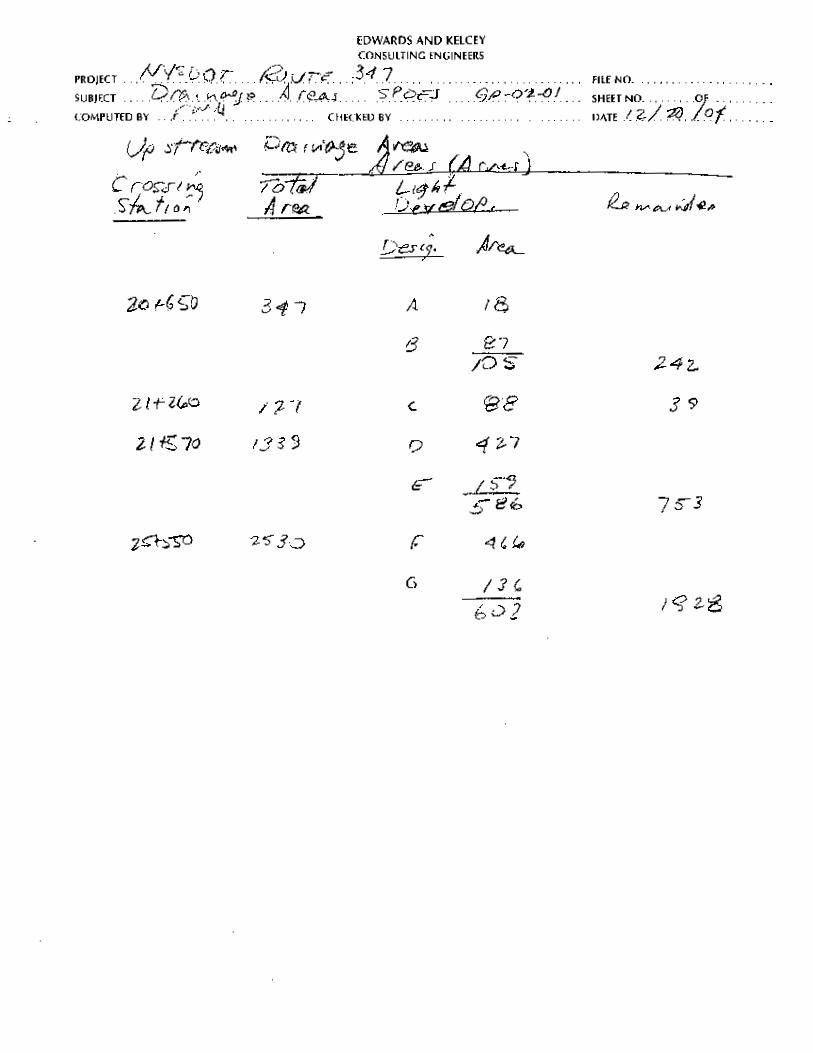
The hydrologic evaluation was performed at the point of discharge of the roadway drainage pipe
to the existing stream at each of the four existing discharge locations. The roadway area that
contributes runoff to the stream, the total contributing area to the stream at the point where the
roadway pipe discharge to the stream, and the percent of the total contributing area represented by
the roadway runoff contributing area, are summarized for each discharge location in Table 3.
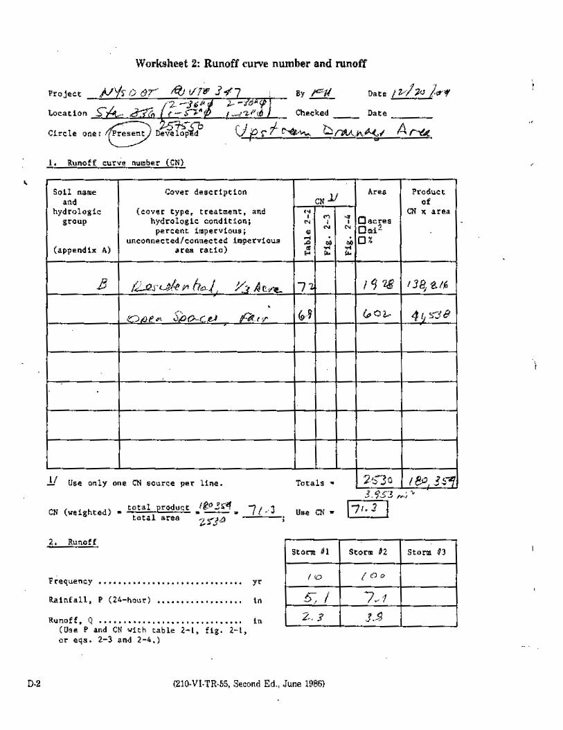
Table 3 Contributing Drainage Areas Discharge
Station Roadway Area
(acres) Total Area (acres) Roadway Percent
20+630 11.1 347 3.1 21+230 6.6 127 5.2 21+580 12.7 1,339 1.0 25+555 43.1 2,530 1.7
Table 3 demonstrates that the contributing project area is less than ten percent of the total
contributing drainage area. This appears inconsistent with the requirement that the hydrologic
evaluation be performed at the point where the project area is ten percent of the total contributing
area. However, extending the evaluation point farther downstream to the point where the project
area represents ten percent of the evaluation area will only increase the total contributing area and
consequently significantly reduce the percentage of the total area represented by the roadway
contributing area. Similarly, increasing the total contributing area reduces the percentage
increase in runoff resulting from the roadway project.
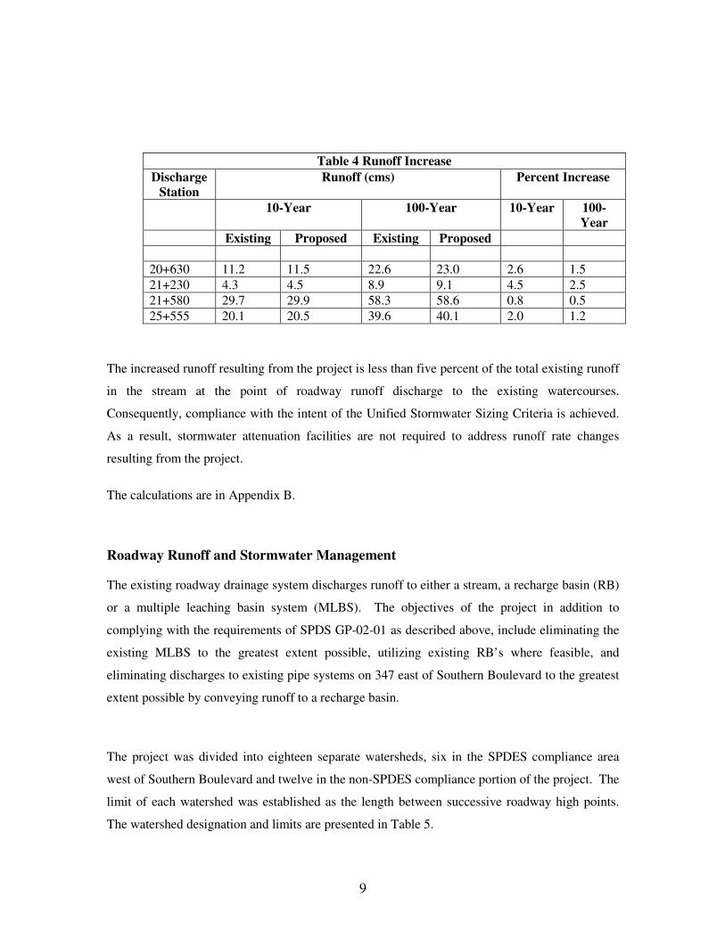
The runoff in each stream at the point of discharge from the roadway drainage system from the
roadway for the existing and proposed conditions and the resultant percent increase, based on the
hydrologic computations, are summarized in Table 4
9
Table 4 Runoff Increase Discharge
Station Runoff (cms) Percent Increase
10-Year 100-Year 10-Year 100-Year
Existing Proposed Existing Proposed 20+630 11.2 11.5 22.6 23.0 2.6 1.5 21+230 4.3 4.5 8.9 9.1 4.5 2.5 21+580 29.7 29.9 58.3 58.6 0.8 0.5 25+555 20.1 20.5 39.6 40.1 2.0 1.2
The increased runoff resulting from the project is less than five percent of the total existing runoff
in the stream at the point of roadway runoff discharge to the existing watercourses.
Consequently, compliance with the intent of the Unified Stormwater Sizing Criteria is achieved.
As a result, stormwater attenuation facilities are not required to address runoff rate changes
resulting from the project.
The calculations are in Appendix B.
Roadway Runoff and Stormwater Management
The existing roadway drainage system discharges runoff to either a stream, a recharge basin (RB)
or a multiple leaching basin system (MLBS). The objectives of the project in addition to
complying with the requirements of SPDS GP-02-01 as described above, include eliminating the
existing MLBS to the greatest extent possible, utilizing existing RB’s where feasible, and
eliminating discharges to existing pipe systems on 347 east of Southern Boulevard to the greatest
extent possible by conveying runoff to a recharge basin.
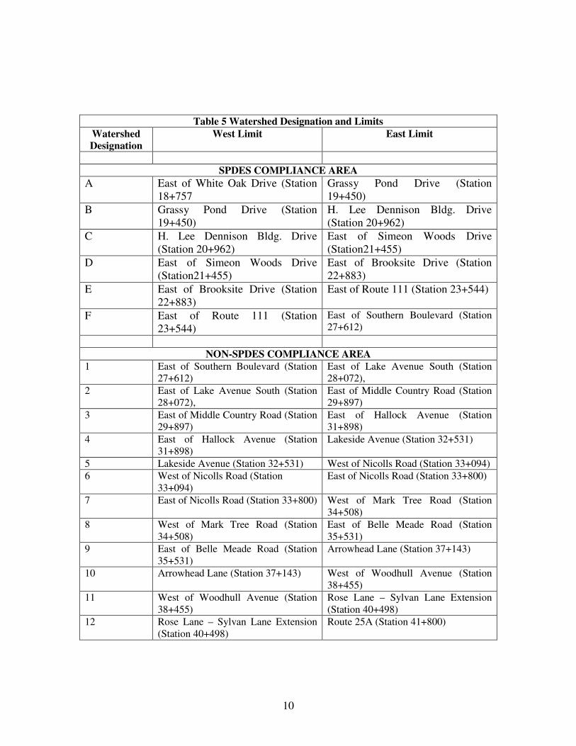
The project was divided into eighteen separate watersheds, six in the SPDES compliance area
west of Southern Boulevard and twelve in the non-SPDES compliance portion of the project. The
limit of each watershed was established as the length between successive roadway high points.
The watershed designation and limits are presented in Table 5.
10
Table 5 Watershed Designation and Limits Watershed Designation
West Limit East Limit
SPDES COMPLIANCE AREA
A East of White Oak Drive (Station 18+757
Grassy Pond Drive (Station 19+450)
B Grassy Pond Drive (Station 19+450)
H. Lee Dennison Bldg. Drive (Station 20+962)
C H. Lee Dennison Bldg. Drive (Station 20+962)
East of Simeon Woods Drive (Station21+455)
D East of Simeon Woods Drive (Station21+455)
East of Brooksite Drive (Station 22+883)
E East of Brooksite Drive (Station 22+883)
East of Route 111 (Station 23+544)
F East of Route 111 (Station 23+544)
East of Southern Boulevard (Station 27+612)
NON-SPDES COMPLIANCE AREA
1 East of Southern Boulevard (Station 27+612)
East of Lake Avenue South (Station 28+072),
2 East of Lake Avenue South (Station 28+072),
East of Middle Country Road (Station 29+897)
3 East of Middle Country Road (Station 29+897)
East of Hallock Avenue (Station 31+898)
4 East of Hallock Avenue (Station 31+898)
Lakeside Avenue (Station 32+531)
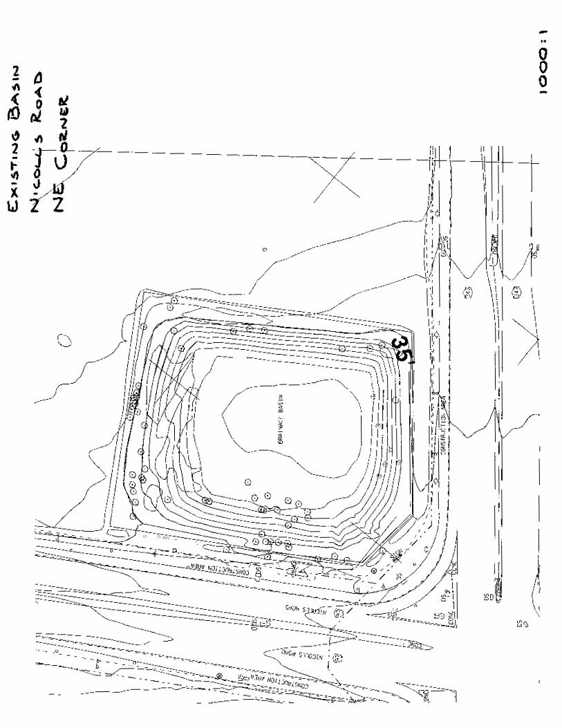
5 Lakeside Avenue (Station 32+531) West of Nicolls Road (Station 33+094) 6 West of Nicolls Road (Station
33+094) East of Nicolls Road (Station 33+800)
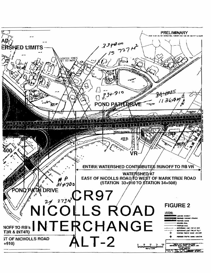
7 East of Nicolls Road (Station 33+800) West of Mark Tree Road (Station 34+508)
8 West of Mark Tree Road (Station 34+508)
East of Belle Meade Road (Station 35+531)
9 East of Belle Meade Road (Station 35+531)
Arrowhead Lane (Station 37+143)
10 Arrowhead Lane (Station 37+143) West of Woodhull Avenue (Station 38+455)
11 West of Woodhull Avenue (Station 38+455)
Rose Lane – Sylvan Lane Extension (Station 40+498)
12 Rose Lane – Sylvan Lane Extension (Station 40+498)
Route 25A (Station 41+800)
11
Conveyance to each proposed WQB will be through a closed pipe system. Runoff that
exceeds the storage volume of each proposed WQB will breach the control spillway set
an elevation below the top of the berm for the WQB, and proceed through the adjacent
wetlands to a receiving water body with a culvert crossing. Runoff conveyed to each
existing water body with a stream crossing that is not delivered to a WQB will be
conveyed to the culvert crossing location in a closed pipe system. Runoff delivered to
each RB will be conveyed in a closed pipe system. The absence of a viable site for the
installation of a RB in watershed # 4 and # 5 requires the installation of a conveyance
pipe that breaches the high point between the watersheds to deliver the runoff to the RB’s
in the adjacent watershed # 6.
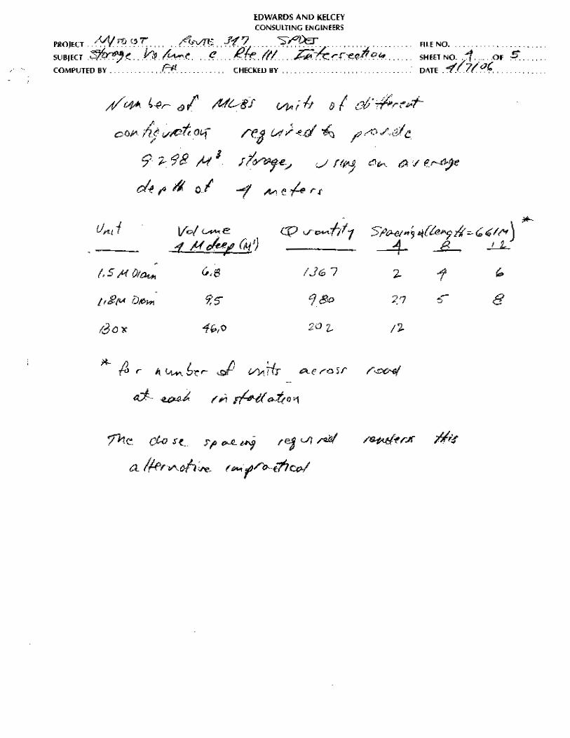
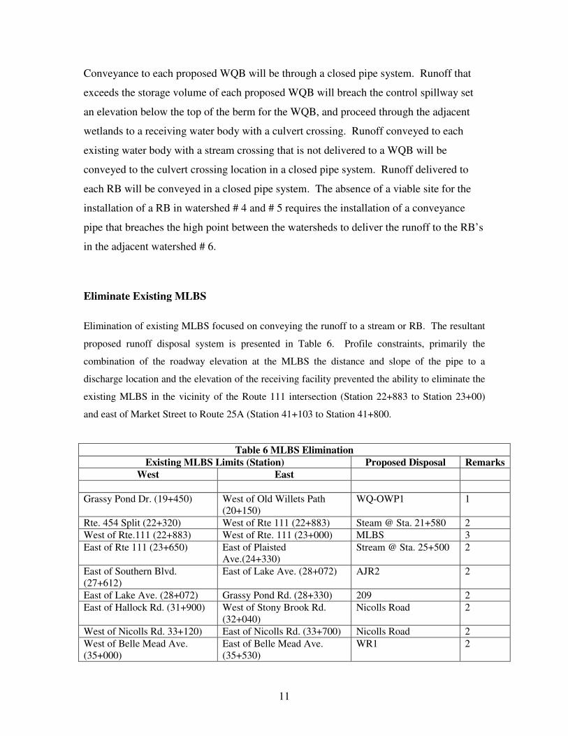
Eliminate Existing MLBS
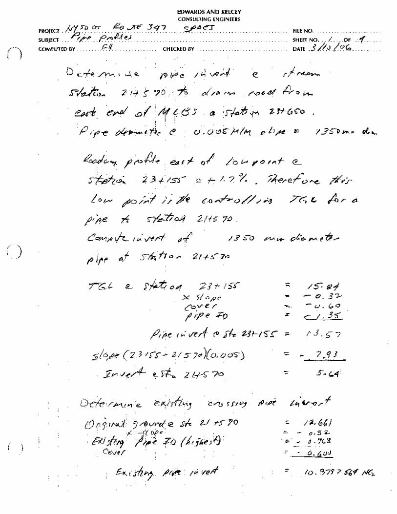
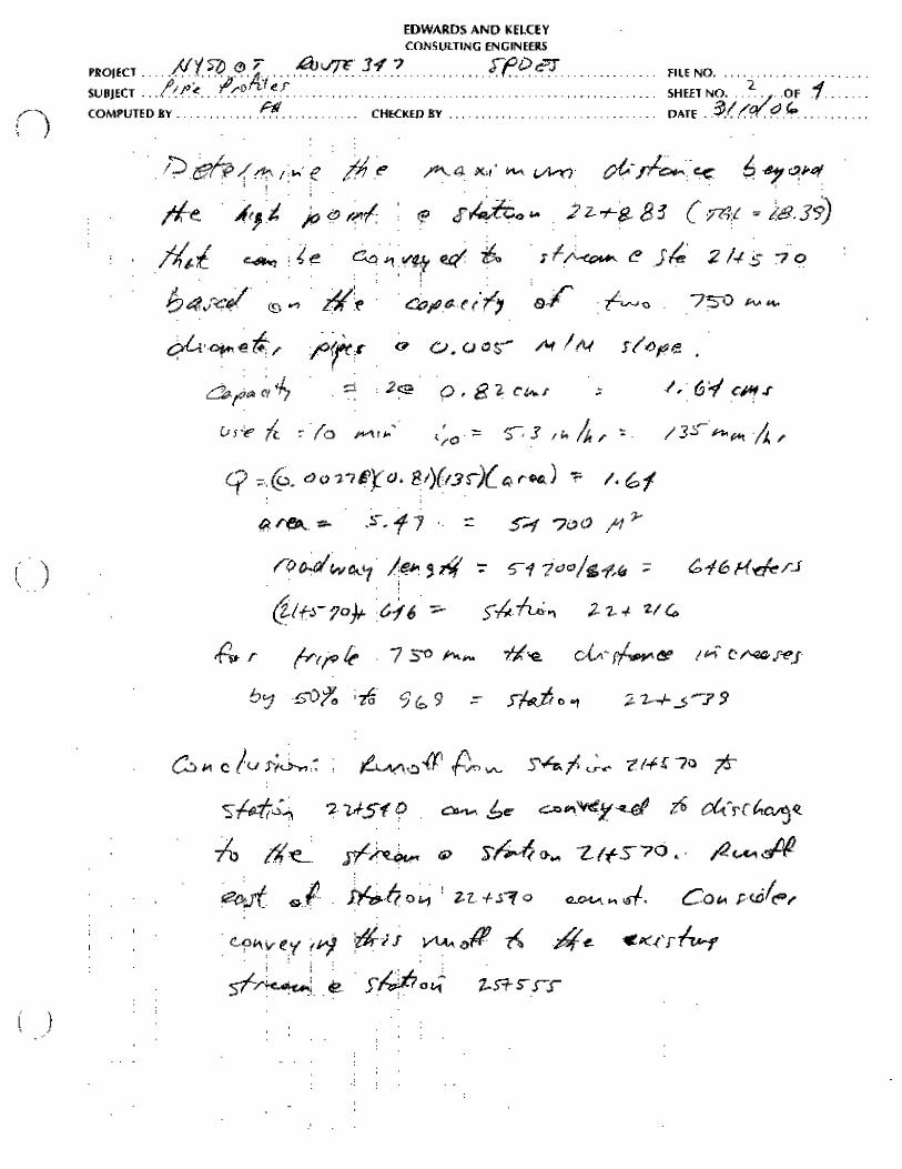
Elimination of existing MLBS focused on conveying the runoff to a stream or RB. The resultant
proposed runoff disposal system is presented in Table 6. Profile constraints, primarily the
combination of the roadway elevation at the MLBS the distance and slope of the pipe to a
discharge location and the elevation of the receiving facility prevented the ability to eliminate the
existing MLBS in the vicinity of the Route 111 intersection (Station 22+883 to Station 23+00)
and east of Market Street to Route 25A (Station 41+103 to Station 41+800.
Table 6 MLBS Elimination Existing MLBS Limits (Station) Proposed Disposal Remarks
West East Grassy Pond Dr. (19+450) West of Old Willets Path
(20+150) WQ-OWP1 1
Rte. 454 Split (22+320) West of Rte 111 (22+883) Steam @ Sta. 21+580 2 West of Rte.111 (22+883) West of Rte. 111 (23+000) MLBS 3 East of Rte 111 (23+650) East of Plaisted
Ave.(24+330) Stream @ Sta. 25+500 2
East of Southern Blvd. (27+612)
East of Lake Ave. (28+072) AJR2 2
East of Lake Ave. (28+072) Grassy Pond Rd. (28+330) 209 2 East of Hallock Rd. (31+900) West of Stony Brook Rd.
(32+040) Nicolls Road 2
West of Nicolls Rd. 33+120) East of Nicolls Rd. (33+700) Nicolls Road 2 West of Belle Mead Ave. (35+000)
East of Belle Mead Ave. (35+530)
WR1 2

12
Table 6 MLBS Elimination Existing MLBS Limits (Station) Proposed Disposal Remarks
West East East of Wireless Rd. (36+300) West of Arrowhead La.
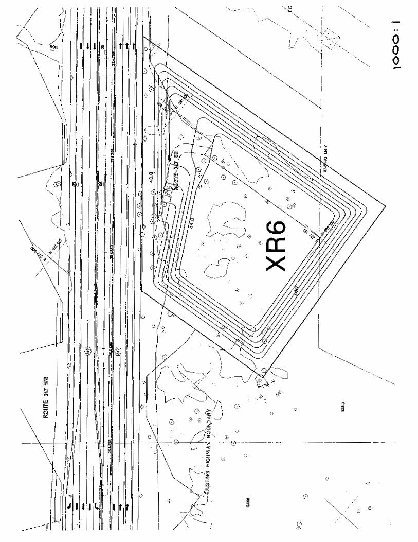
(36+500) XR6 2
West of Arrowhead La. (36+940)
Arrowhead La. (37+143) XR6 2
East of Old town Rd. (38+110) West of Terryville Rd. (39+107)
15AR5 2
East of Rte. 112 (40+498) East of Market St, (41+103) 17AR4 2 East of Market St. (41+103) Route 25A(41+800) MLBS 2 Remarks:
1. Overflow proceeds overland through adjacent wetlands to the stream at Station
20+630.
2. Runoff to be discharged to an existing stream or a proposed RB will be conveyed in a
closed pipe system.
3. Provide longitudinal pipe infiltration system.
The calculations are in Appendix C
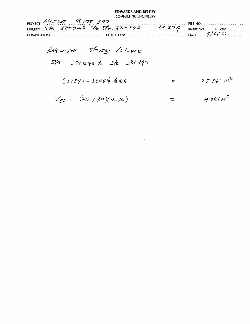
Utilize Existing RB’s
Runoff from a portion of Route 347 is currently discharged to an existing recharge basin (RB) at
five locations. These include the RB in the area between eastbound Northern State Parkway,
New Highway and Parkway Drive South, RB-08 on the eastbound side of Route 347 west of
Autumn Drive, RB-0274 on the south side of Route 111 west of the Route 347 intersection, RB-
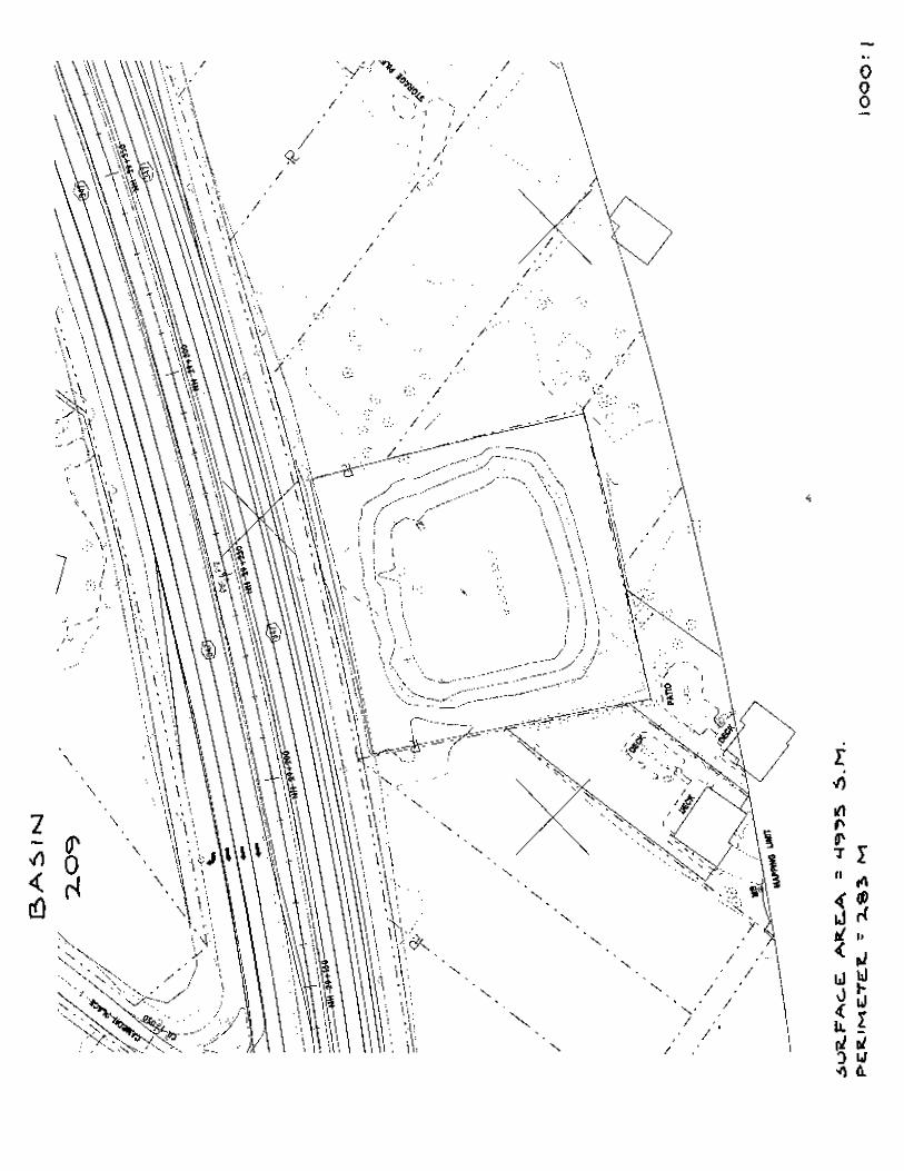
209 on the eastbound side of Route 347 between Browns Road and Middle Country Road (Route
25) and RB-0276 on the eastbound side of Route 347 west of Stony Brook Road.
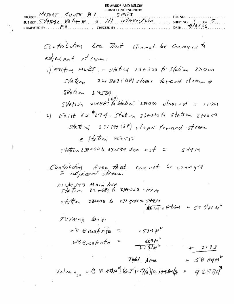
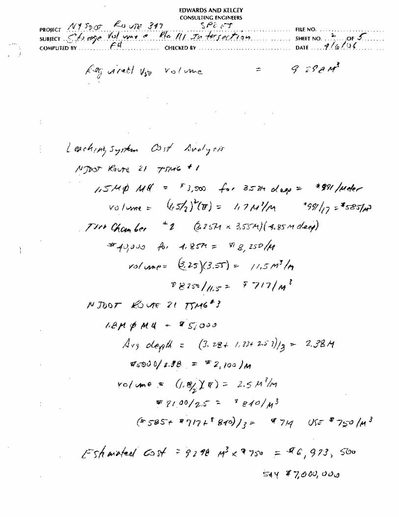
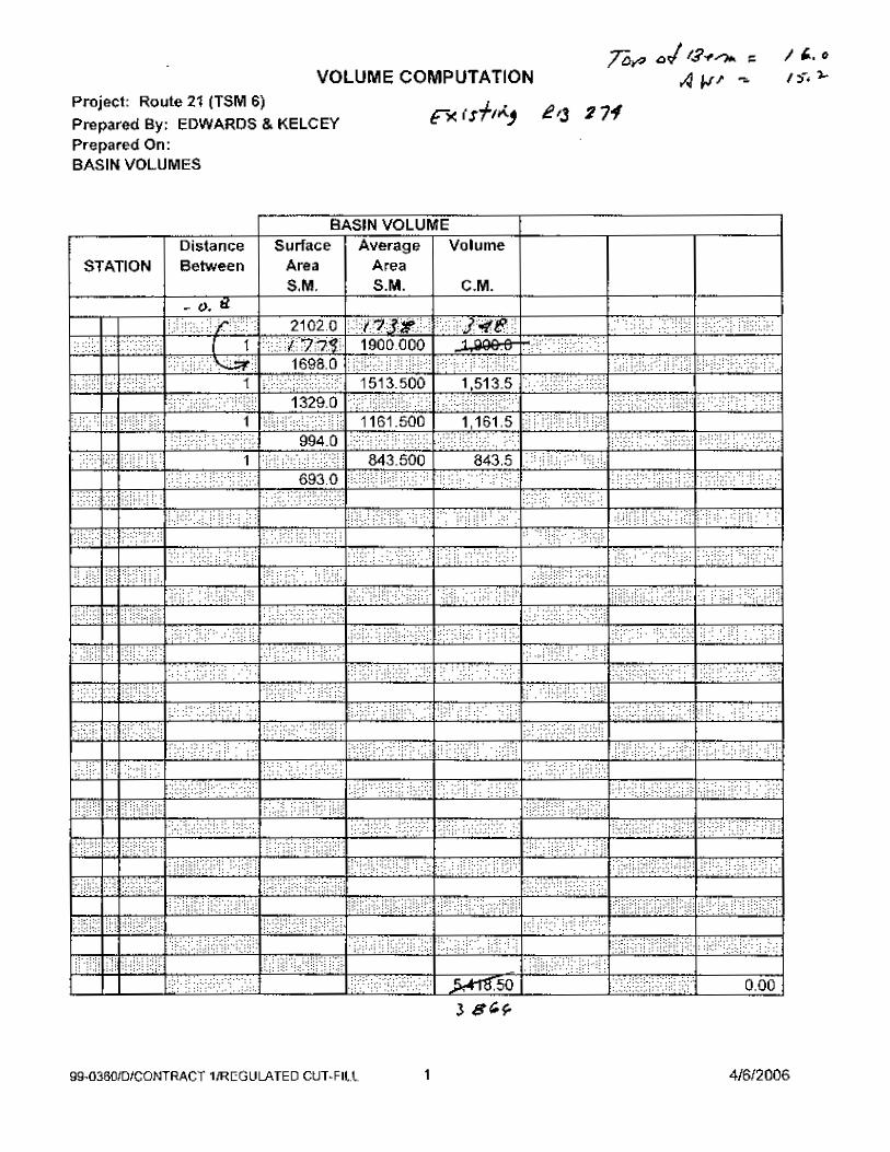
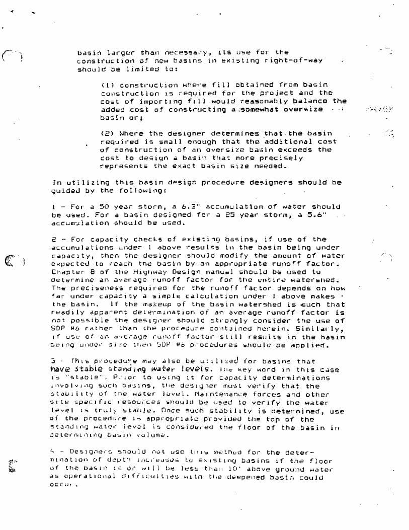
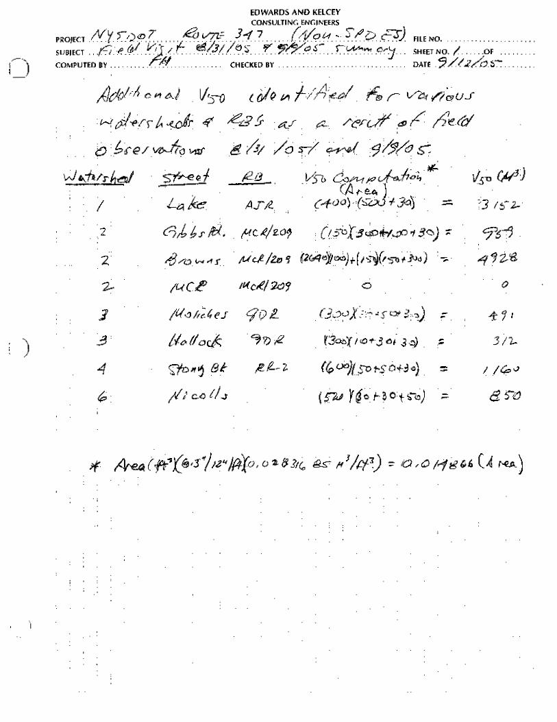
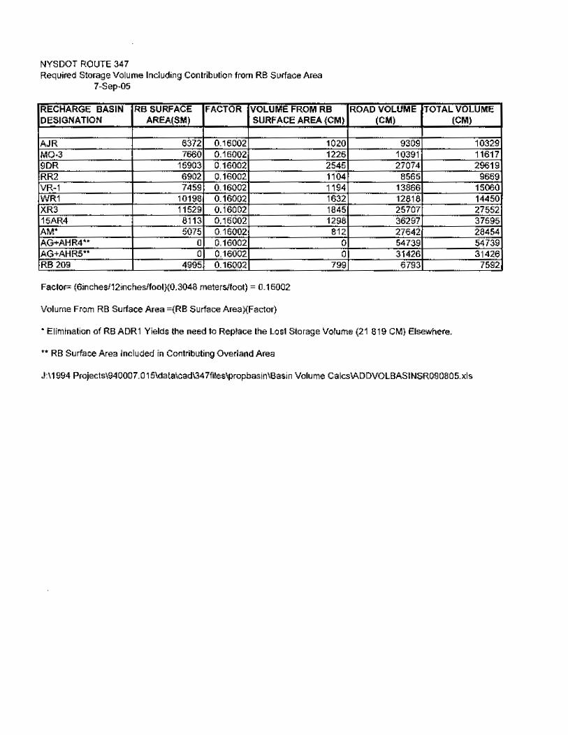
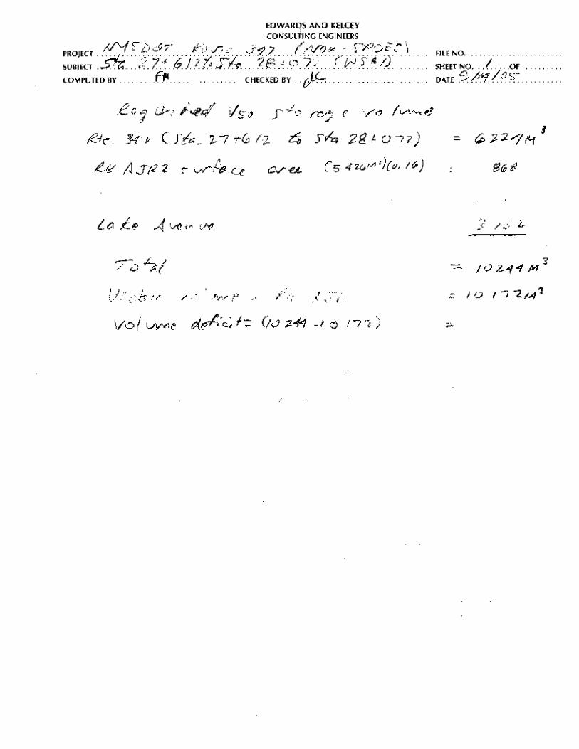
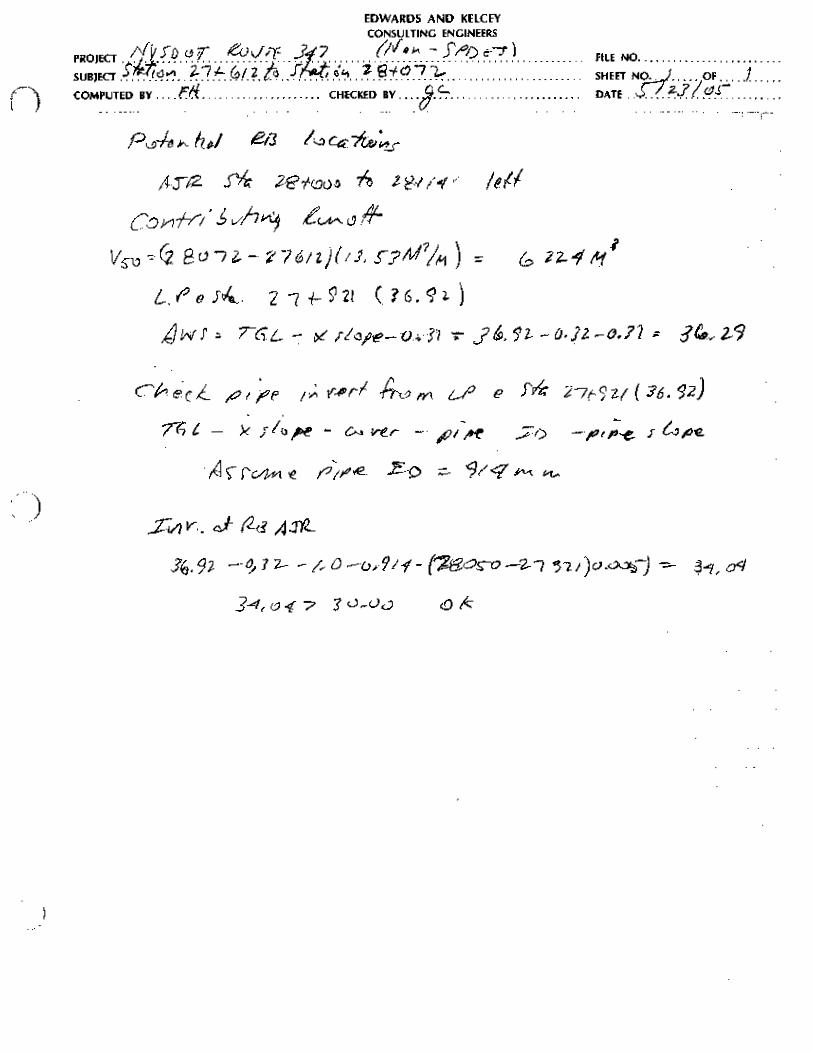
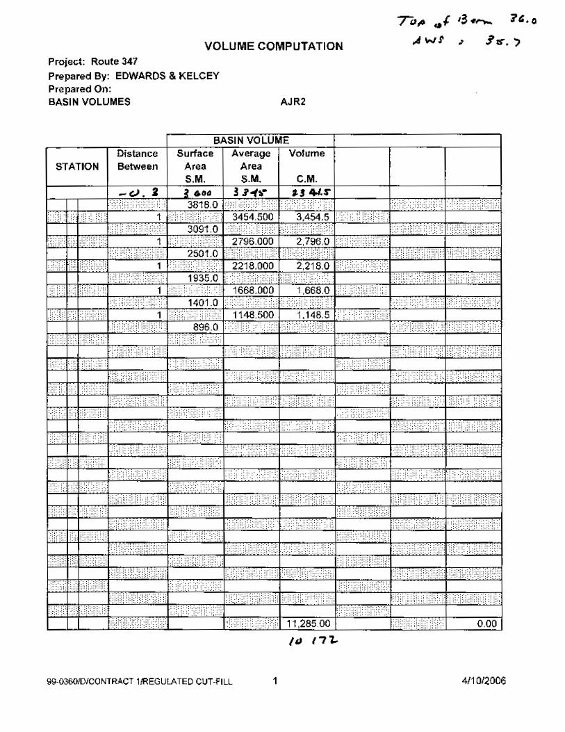
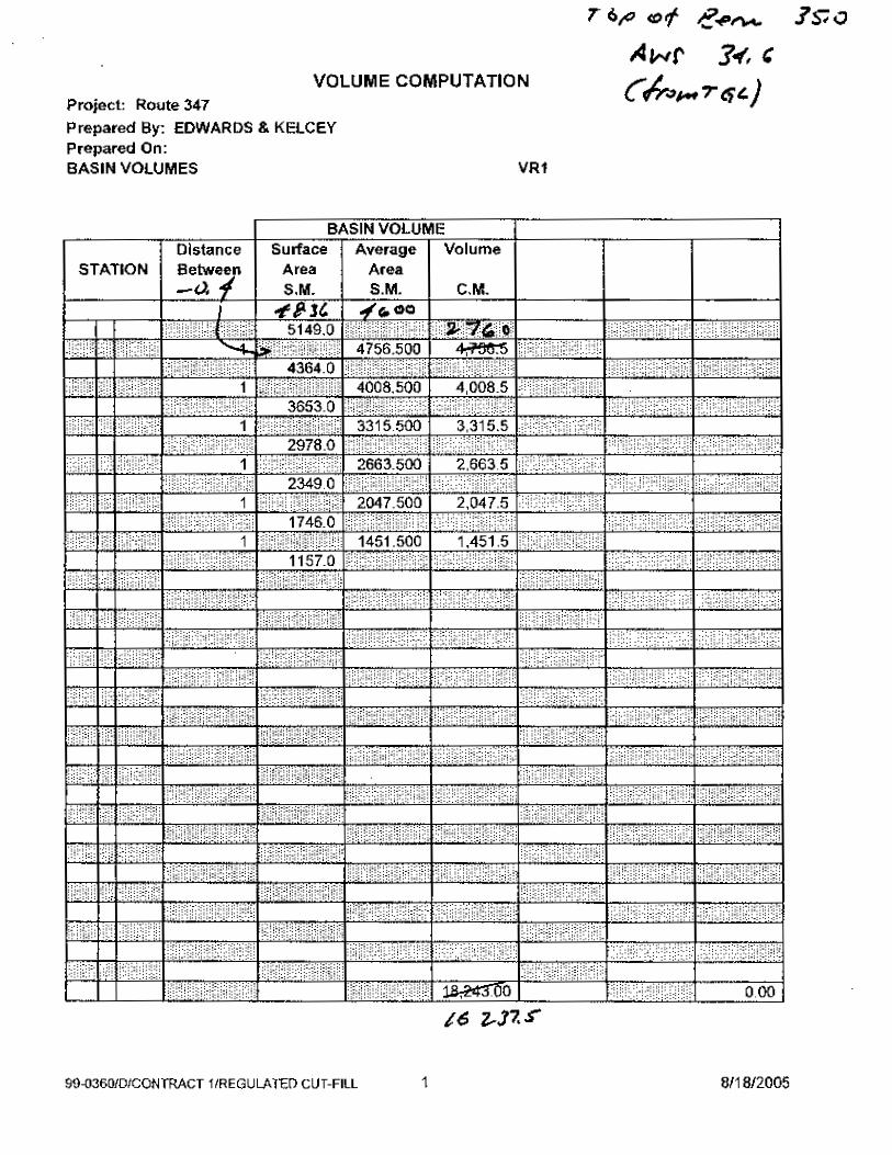
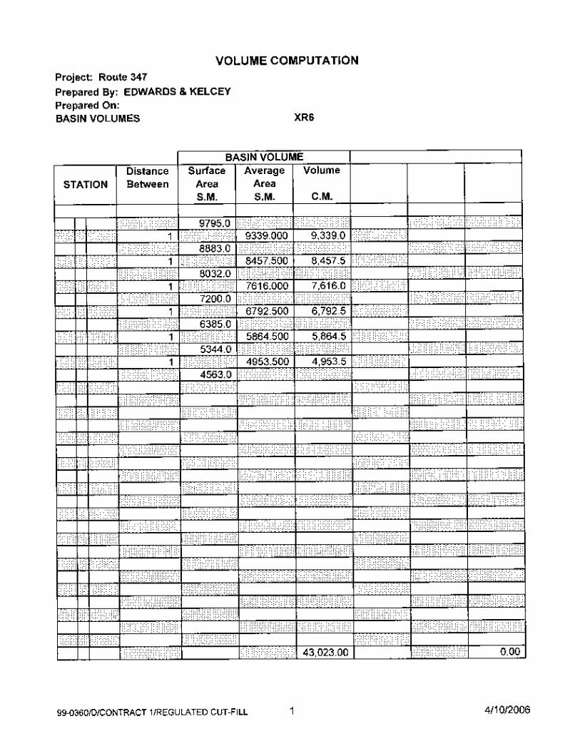
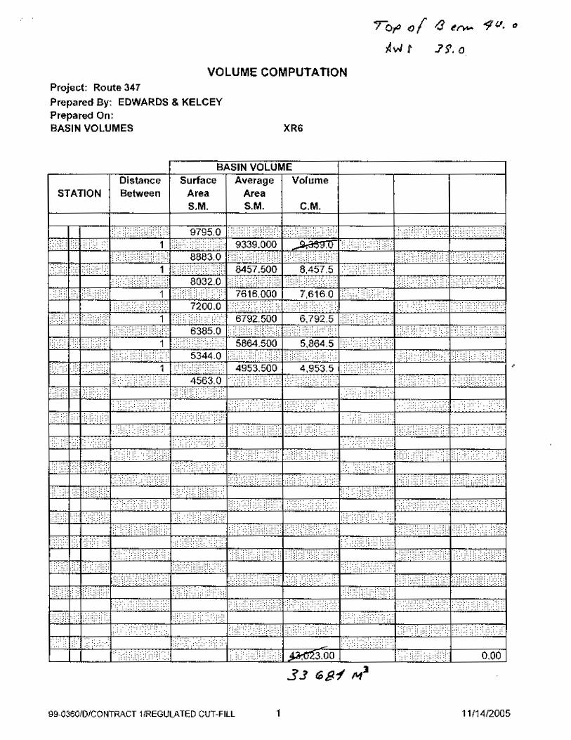
Each of the existing RB’s was evaluated to determine how each could be incorporated into the
design. The volume required to contain the storm with a recurrence interval of once in fifty
years was computed by multiplying the contributing area by 0.16 meters (6.3”) of rainfall in
accordance with DM 92 (20) Recharge Basin Design Criteria to determine the geometric
requirements of each existing RB. The results are summarized below.
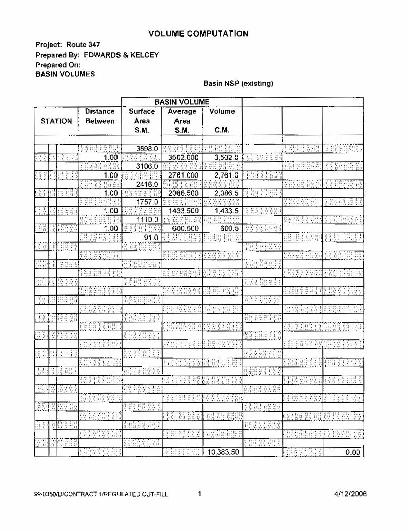
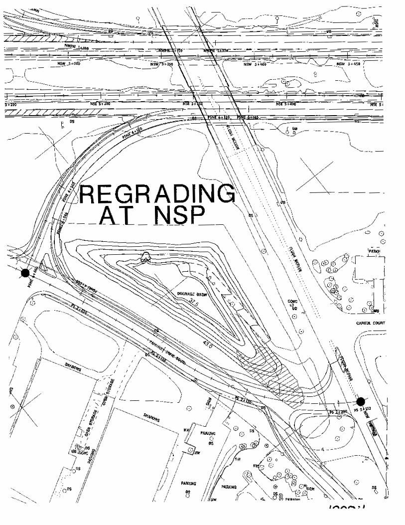
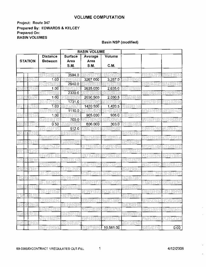
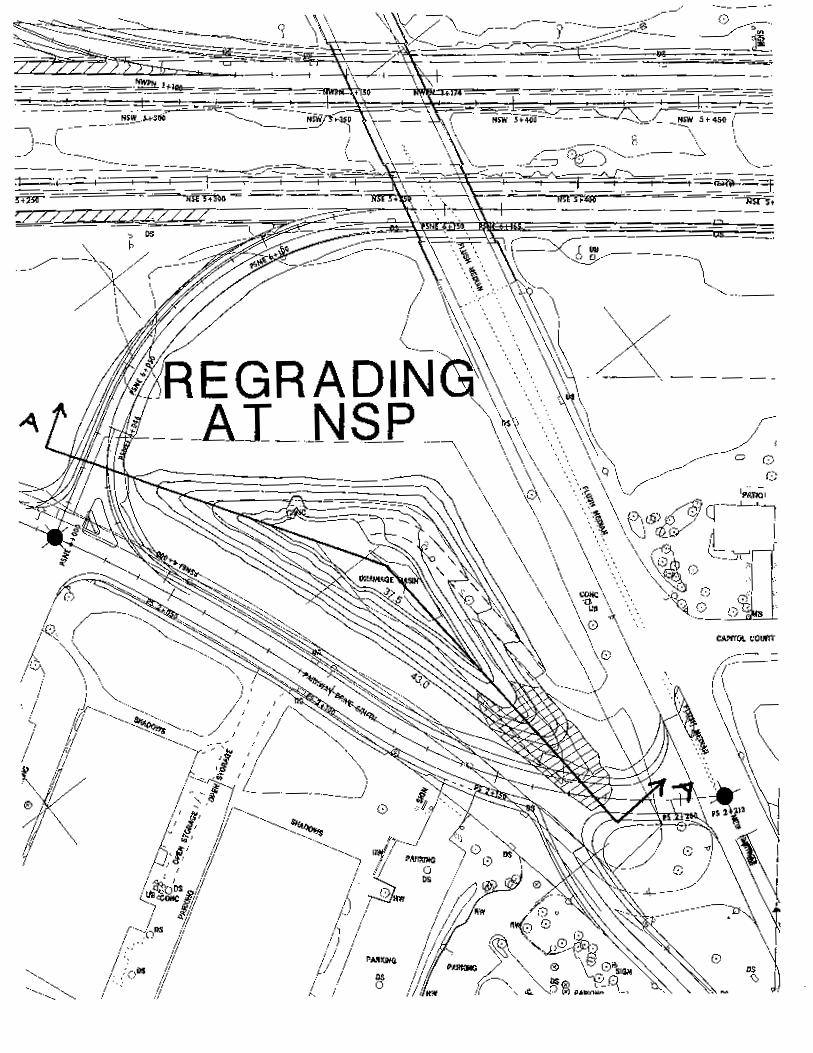
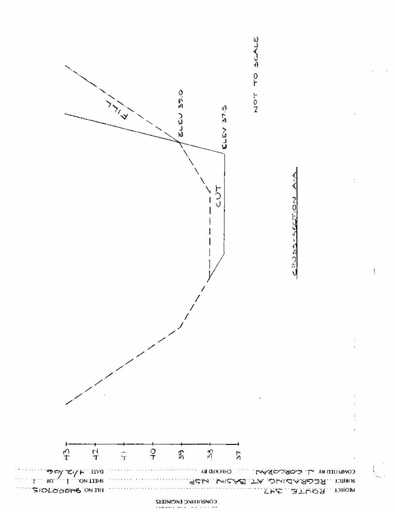
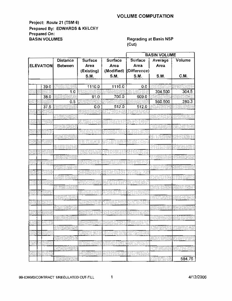
1. RB at Northern State Parkway
The proposed realignment of Parkway Drive South at the intersection with New
Highway introduces fill into the exiting RB No. SP10, thereby reducing the usable
storage volume. This reduced storage volume will be replaced by increasing the
13
slope between the last two contours to the standard one vertical on two horizontal.
This increases the area of the bottom contour and consequently the volume in the RB.
The fill introduced by the project causes a volume loss of approximately 430 cubic
meters as compared to the approximately 585 cubic meters resulting from re-grading
the basin.
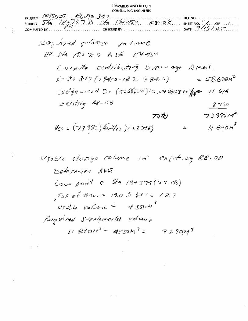
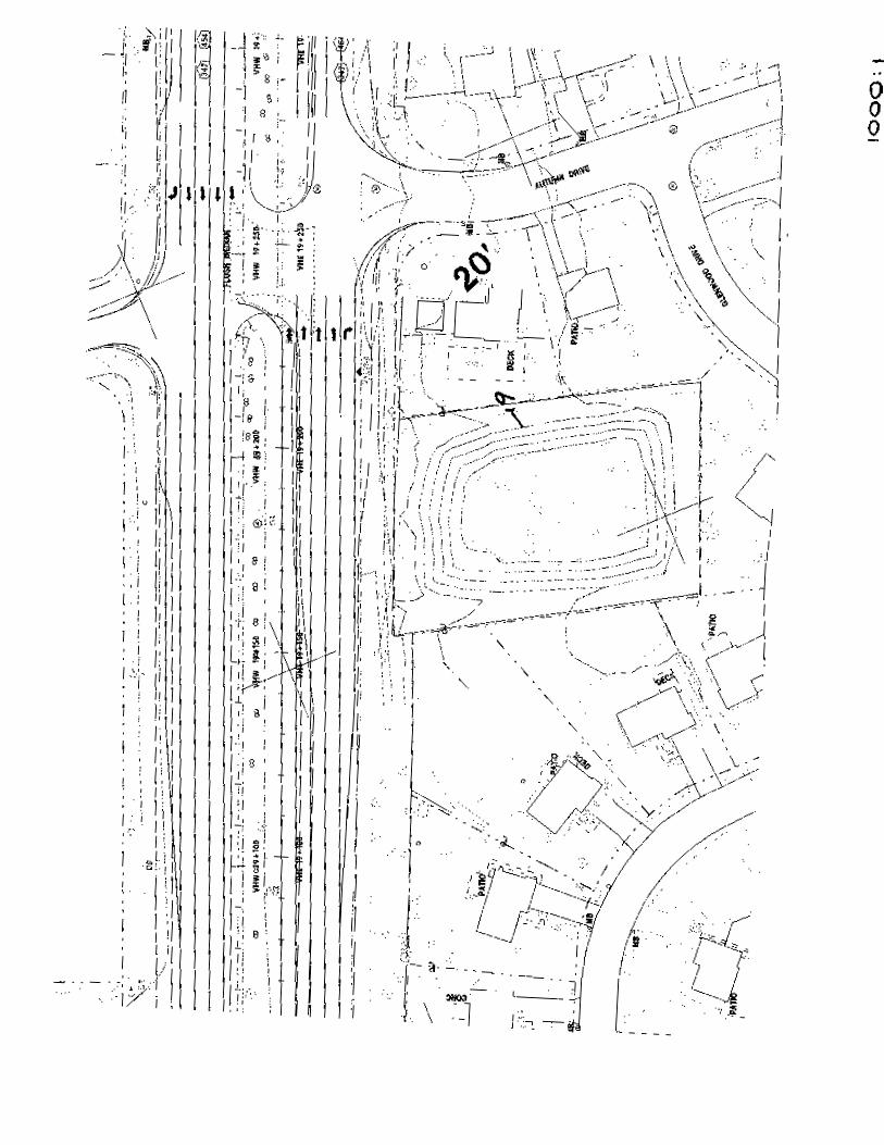
2. RB-08, Eastbound Side of Route 347 West of Autumn Drive
Runoff from approximately between White Oak Drive (Station 18+757) and Grassy
Pond Drive (Station 19+450) is discharged to existing RB No.SP08 located on the
eastbound side of Route 347 west of Autumn Drive. The usable storage volume in
existing RB-08 is approximately 4 550 cubic meters.
The required storage volume is 11 840 cubic meters as compared to a usable storage
volume in existing RB 08 of approximately 4 550 cubic meters. Supplemental RB
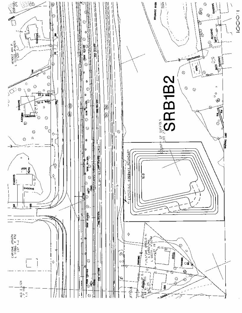
SRB1B2 to be installed in the property on the eastbound side of Route 347 between
Autumn Drive and New Highway currently owned by Suffolk County provides a
usable storage volume of 12 981 cubic meters.
The surface area of supplemental RB SRB1B2 was limited by the configuration,
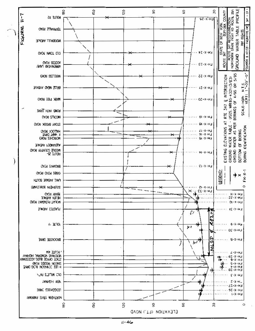
dimensions, ground water table elevation and topography of the candidate site. The
ground water table is approximately seven meters below the existing Route 347
elevation at the roadway centerline between Ledgewood Drive and New Highway.
The bottom will be above the ground water table elevation.
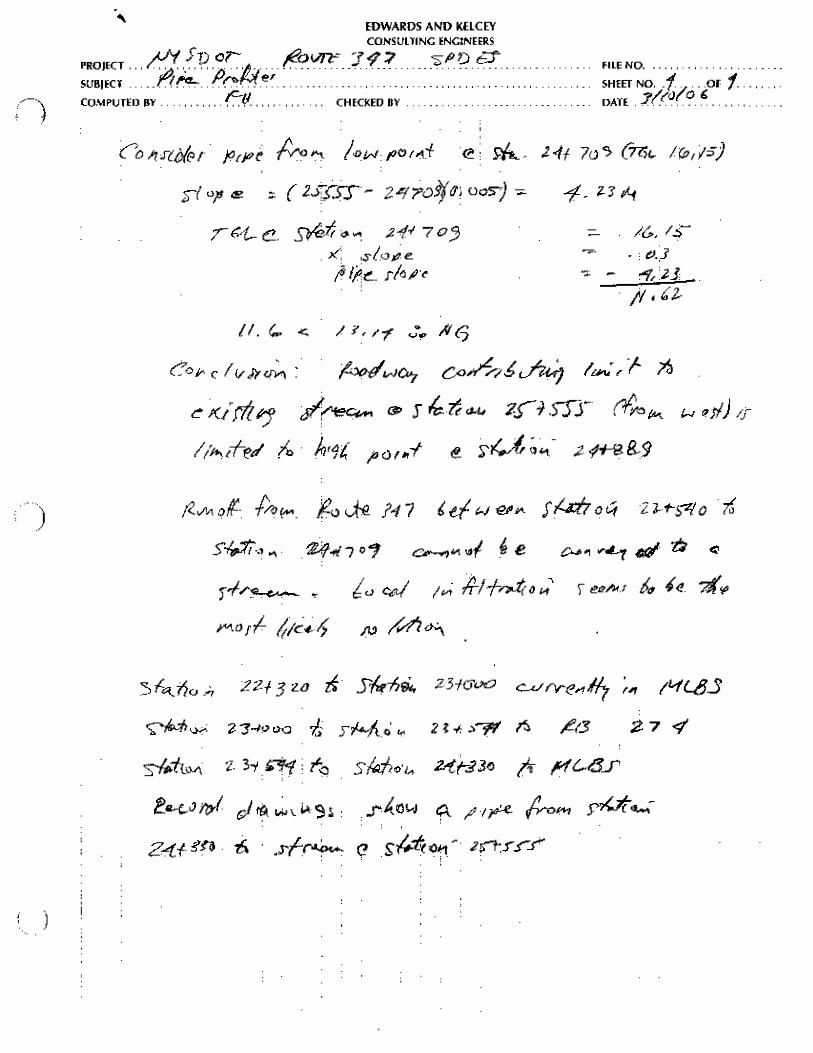
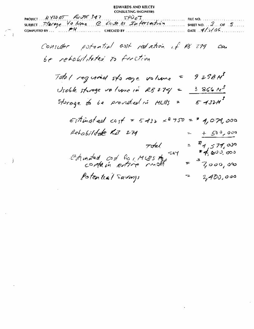
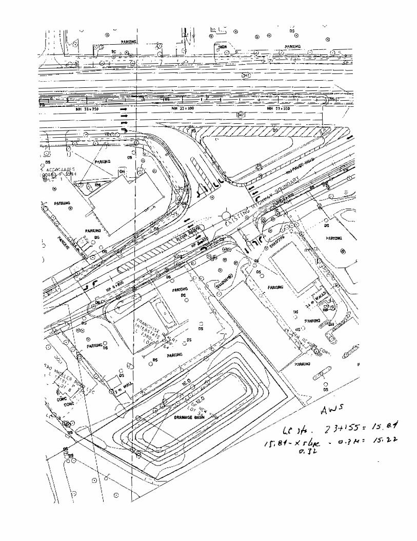
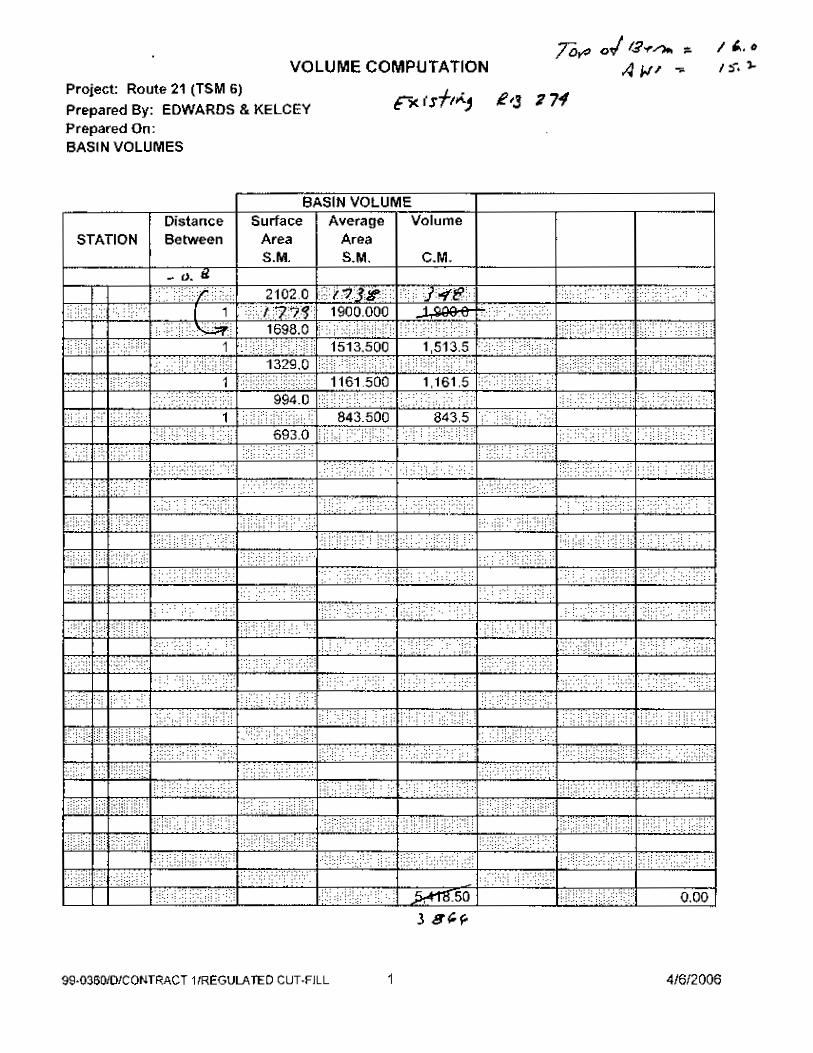
3. RB 0274 – Route 111 West of the Route 347 Intersection
Runoff from the eastbound lanes of Route 347 in the vicinity of the Route 111
intersection (approximately between Station 23+000 and Station 23+650) is discharged
to existing Recharge Basin (RB) – 0274 located on the eastbound side of Route 111 west
of the Route 347 intersection. This basin has a history of standing water because of high
groundwater. Rehabilitation to improve infiltration is highly unlikely. Runoff from the
remainder of Route 347 within these limits is conveyed in a closed pipe system to an
existing pond on the westbound side of Route 347 west of the Route 111 intersection.
Opportunity to enlarge this existing pond is limited, primarily due to the small
area of the exiting lot and encroachment of athletic fields. The apparently shallow
14
depth to groundwater further restricts the ability to increase volume by increasing
the depth. Installation of a longitudinal infiltration pipe system below the
pavement box and above the groundwater table elevation may be the only
opportunity to create additional storage volume for this portion of Route 347.
Runoff from this portion of Route 347 should continue to be delivered to the
existing pond and RB 0274, supplemented by a longitudinal pipe infiltration
system to supplement the storage volume.
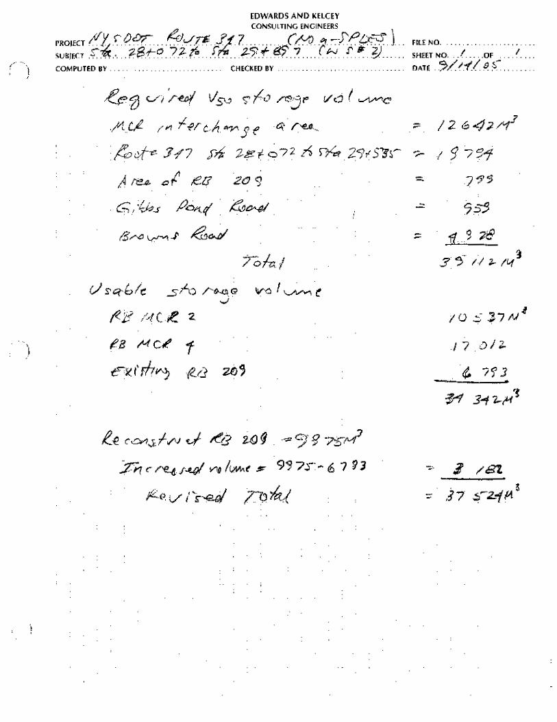
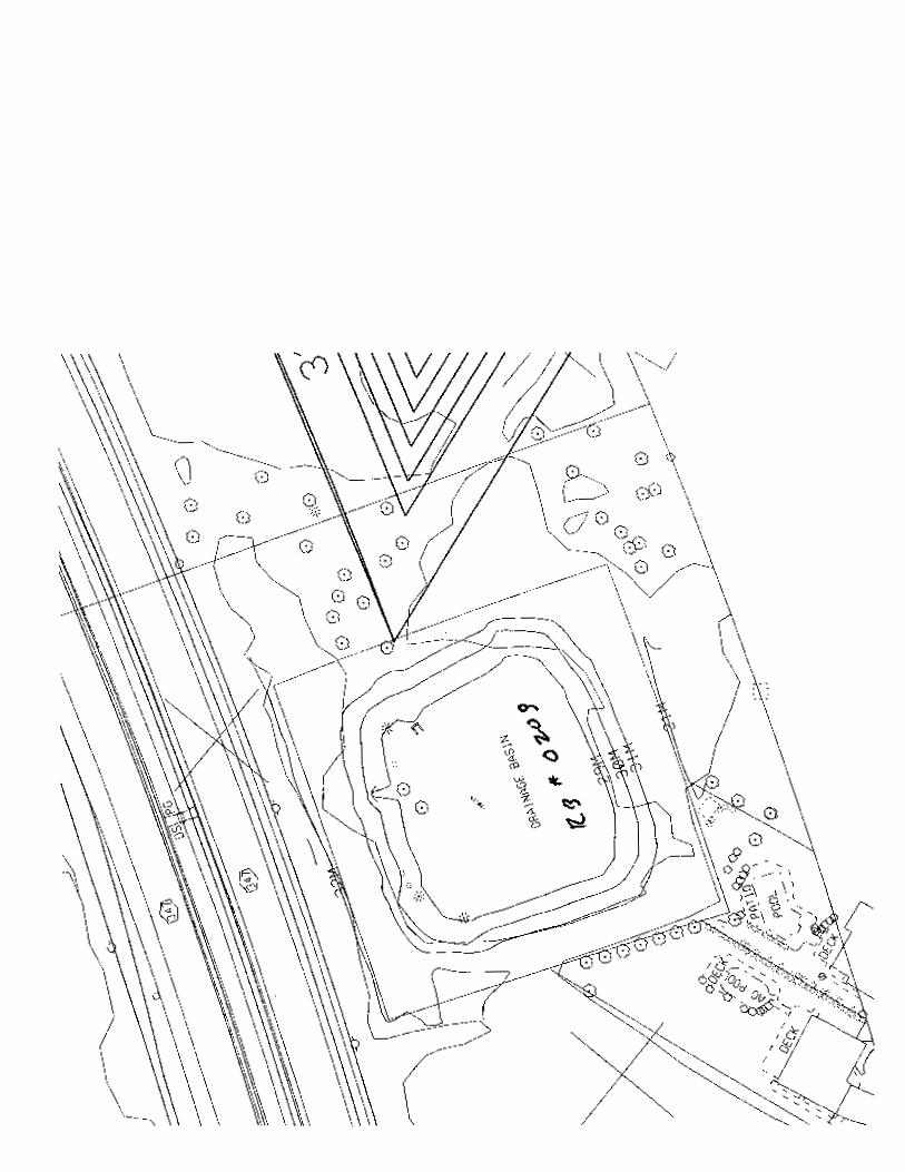
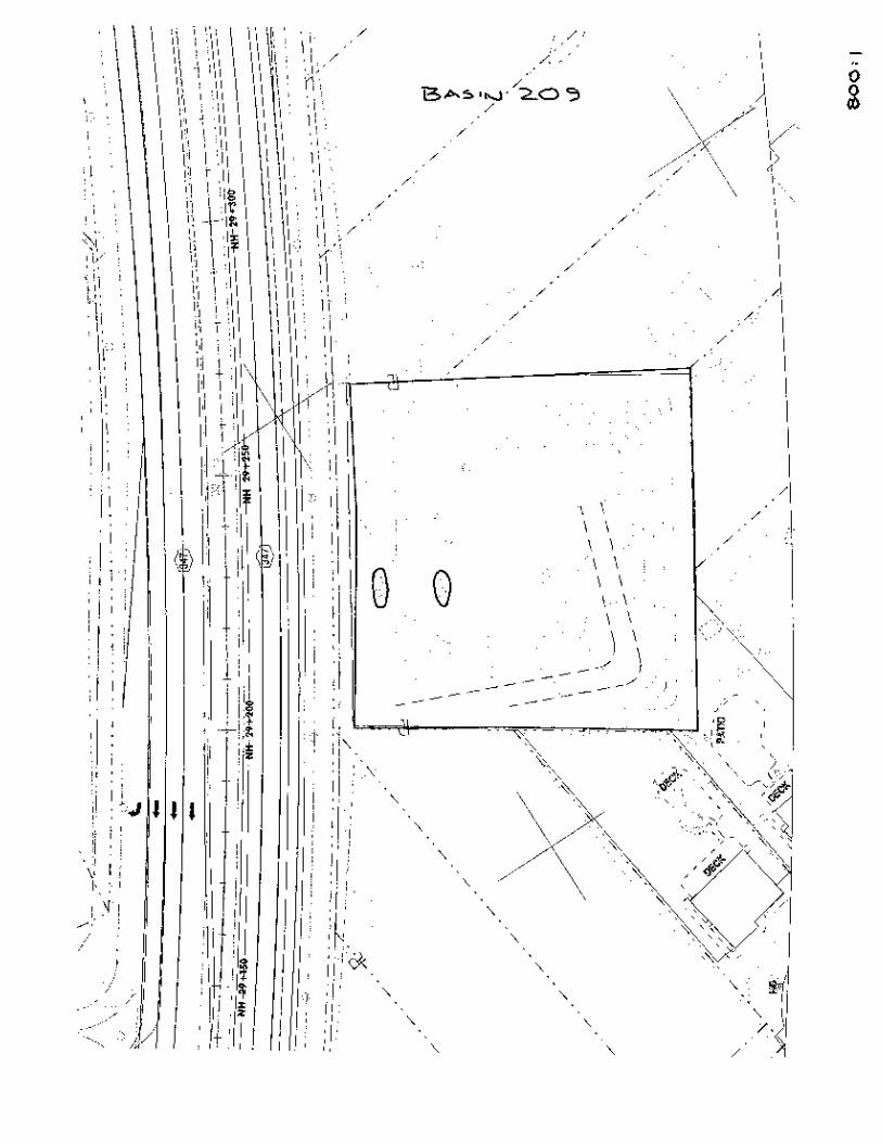
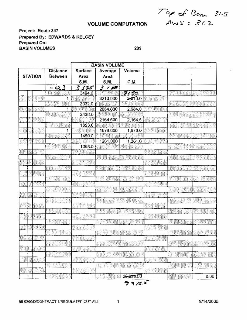
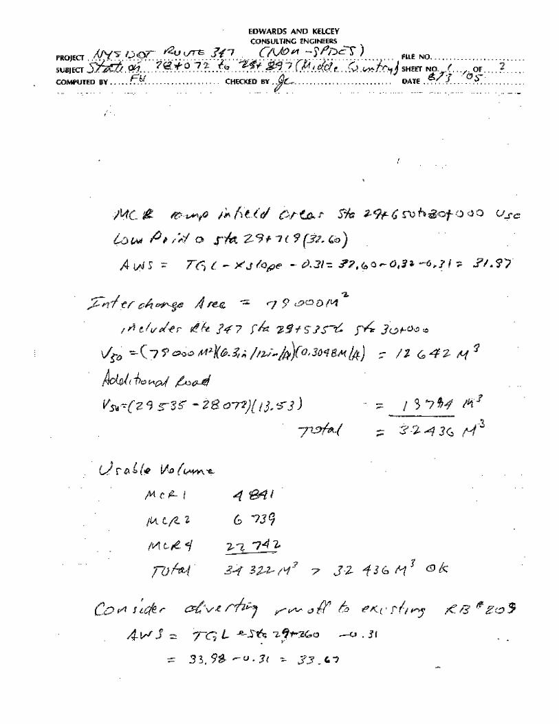
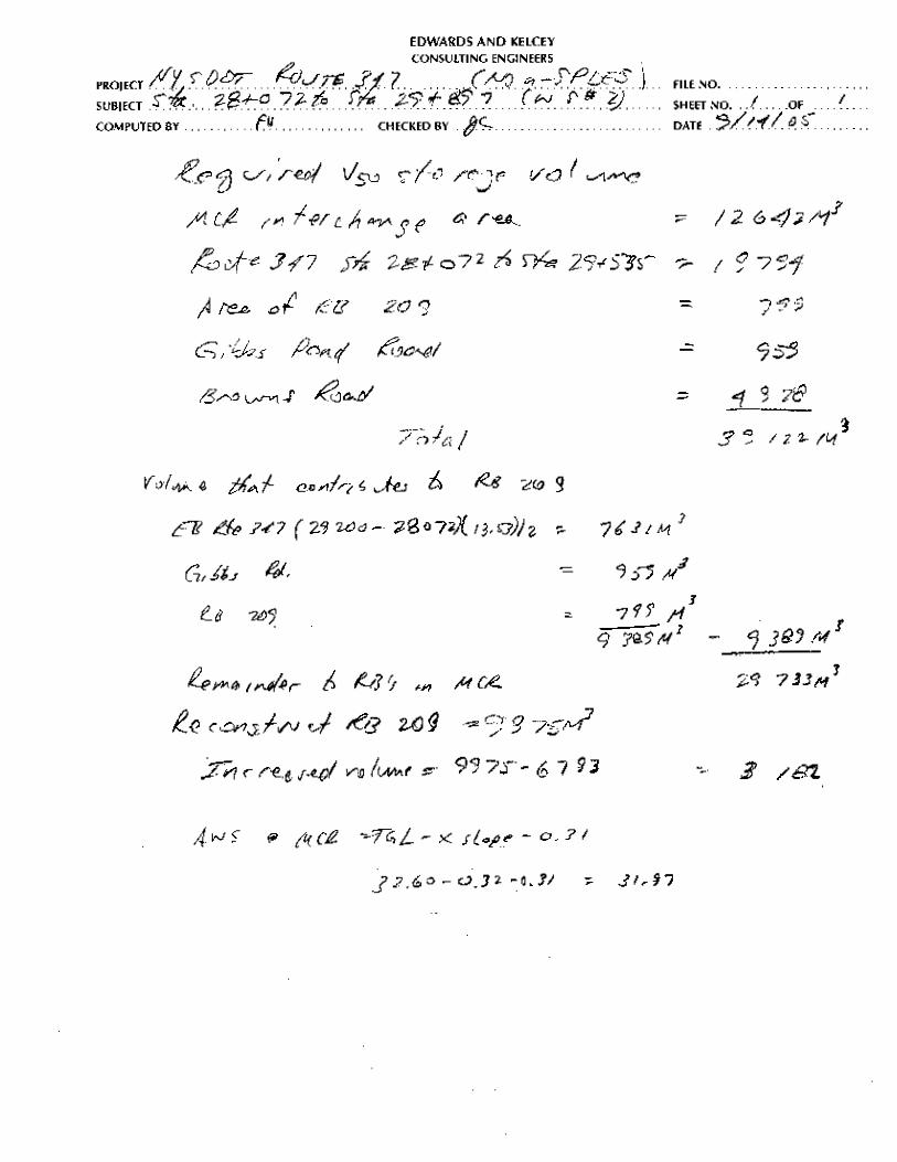
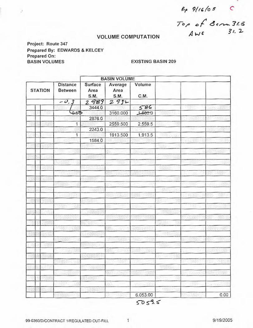
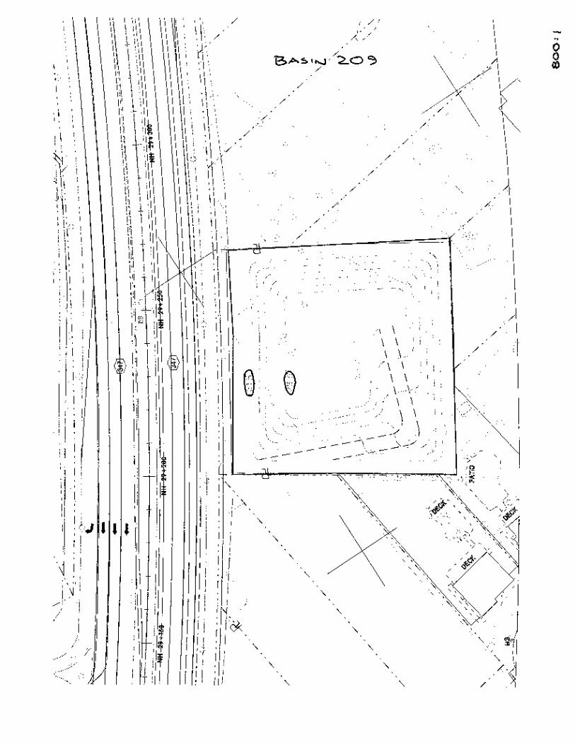
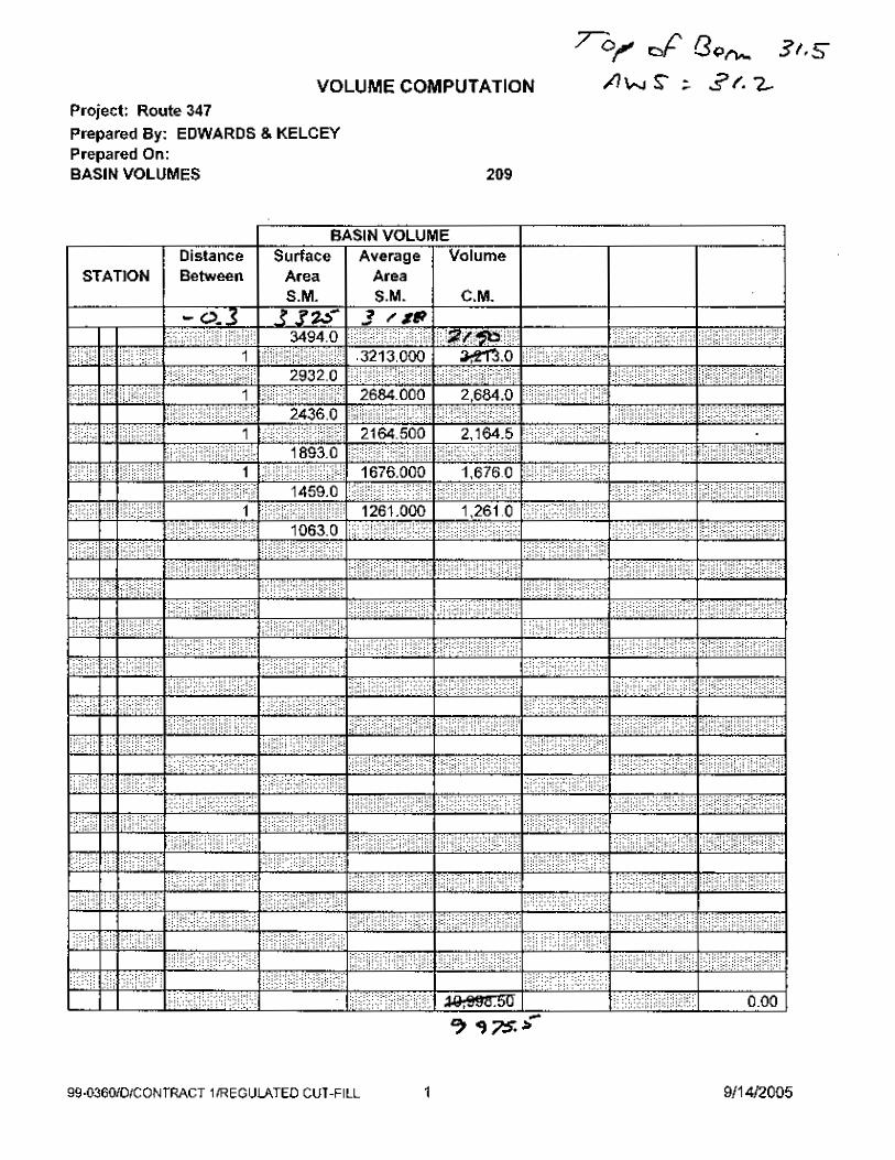
4. RB 209 – Eastbound Side of Route 347 between Browns Road and Route 25
The existing RB provides a usable storage volume of 5 060 cubic meters. The RB
will be re-graded using current RB design criteria to provide a usable storage volume
of 9 975 cubic meters and incorporated into the project.
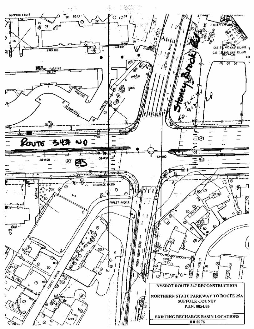
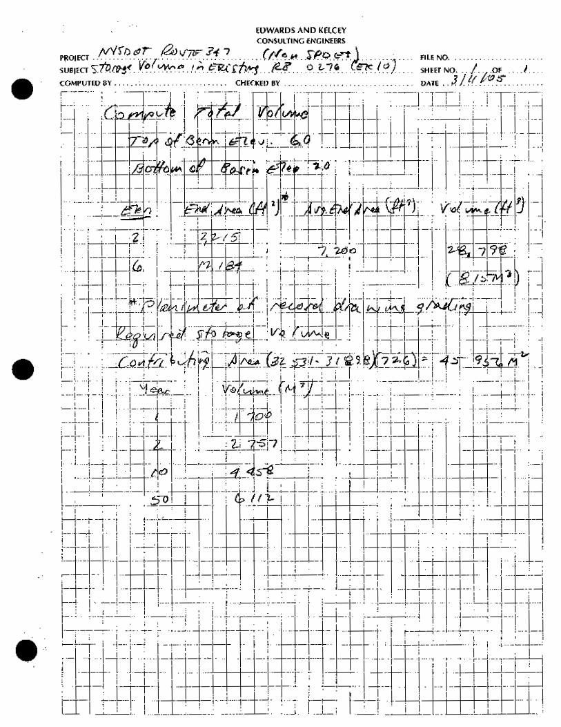
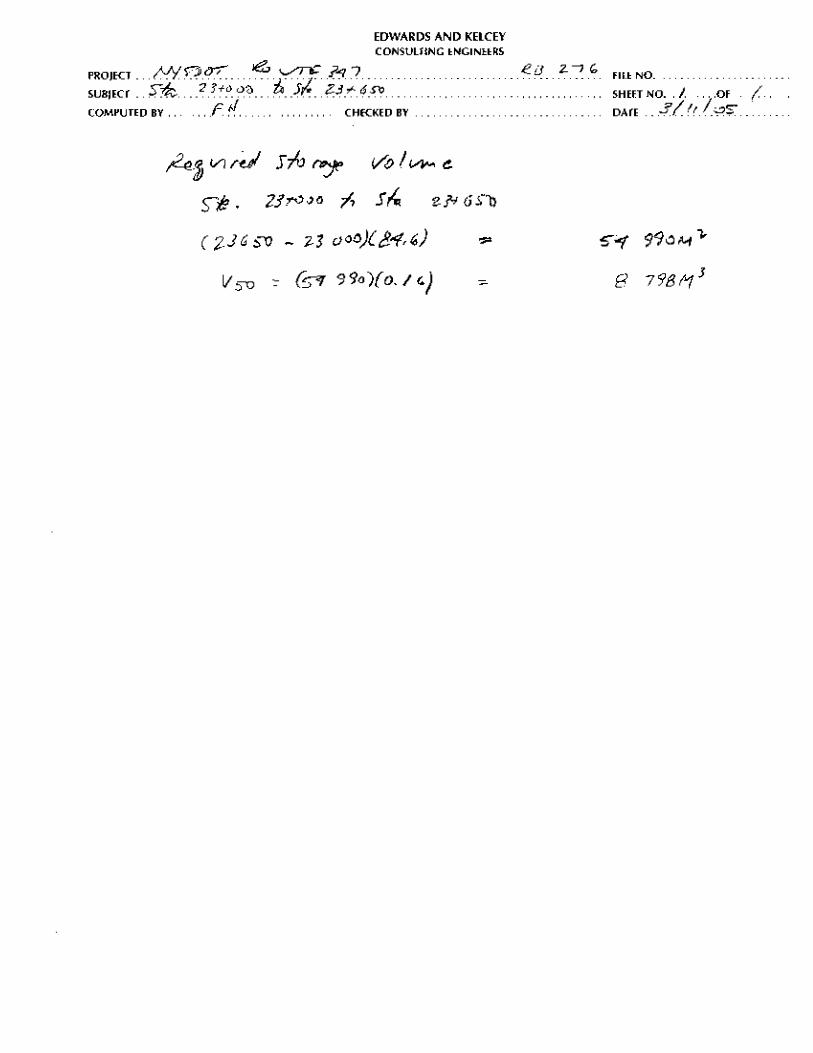
5. RB-0276 – Eastbound Side of Route 347 West of Stony Brook Road
The small size of this RB and the resultant limited usable storage volume warrants
eliminating this RB from the project.
The calculations are in Appendix D.
Eliminate Discharge to Existing Pipe Systems
Eliminating the discharge of roadway runoff to existing pipe crossings of Route 347 is achieved
with the installation of RB’s also known as a dry extended detention pond, dry pond, extended
detention basin, detention pond or an extended detention pond with adequate a usable storage
volume that contains the runoff with a recurrence interval of once in fifty years.
Identification of sites for the installation of a RB focused on areas within the highway boundary.
This optimizes the use of otherwise unusable areas and minimizes the need for additional
property acquisition. Ramp infield areas at proposed grade separated interchanges are ideal
candidate RB sites. When the required storage volume could not be achieved within the highway
boundary, alternatives were considered in the following sequence:
15
1. Expand an existing NYSDOT RB into adjacent vacant land
2. Utilize residual portions of parcels acquired for the roadway project
3. Acquire vacant public property with access denied to Route 347
4. Acquire vacant private property with access denied to Route 347
5. Acquire vacant private property
6. Acquire other private property
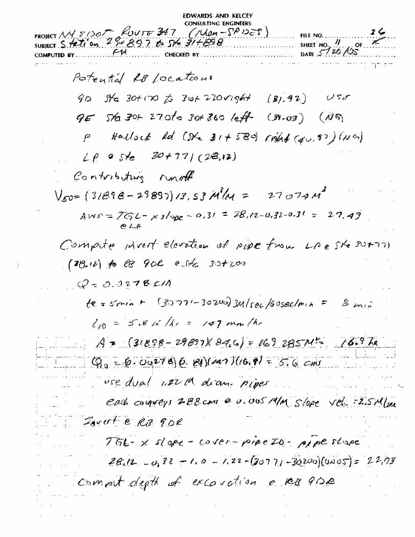
RB’s were located as close as possible to the main line low points. This procedure minimizes the
length of pipe required to convey the runoff to the RB and minimizes the depth of the RB
required to contain the required storage volume
Use of the sequential RB site identification procedure described above occasionally yielded a RB
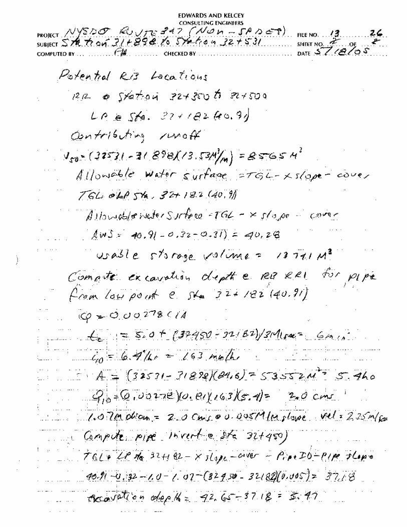
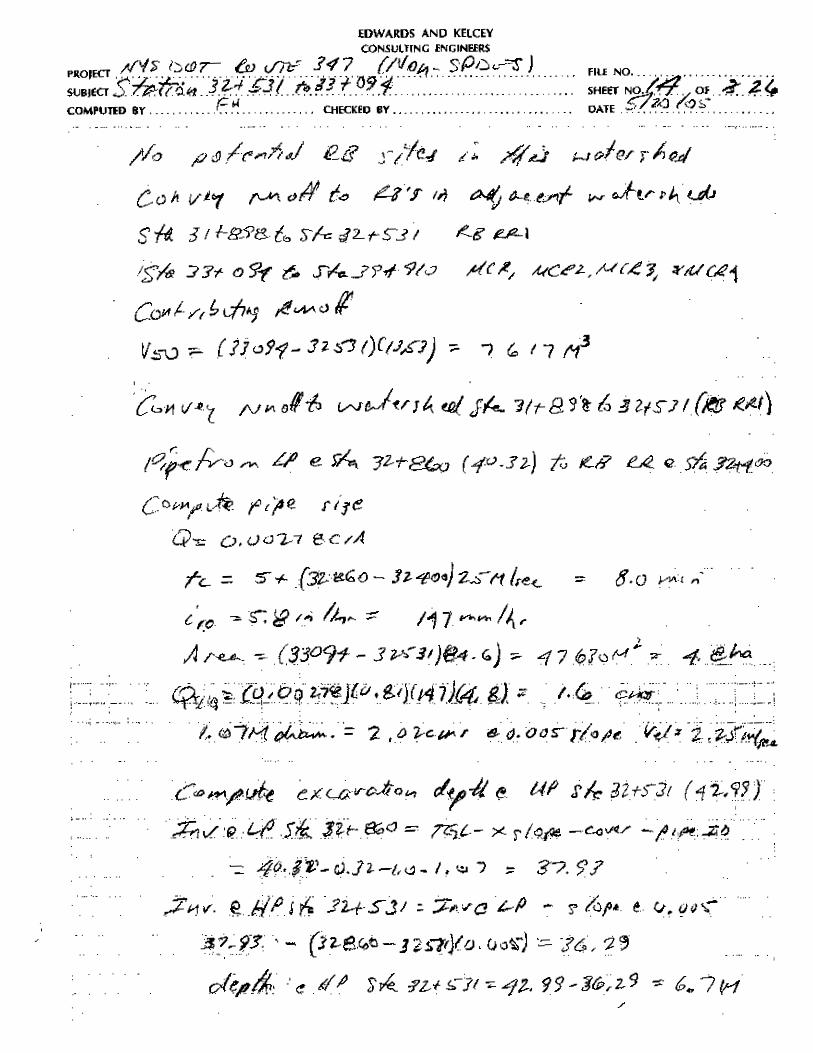
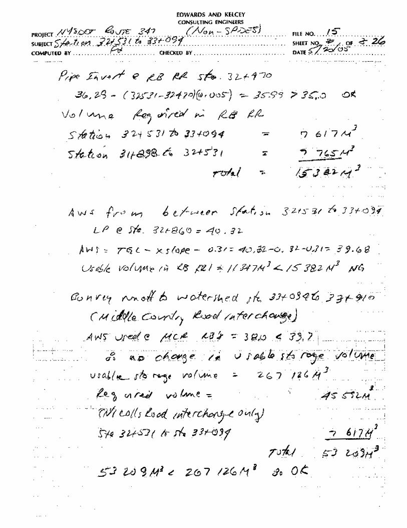
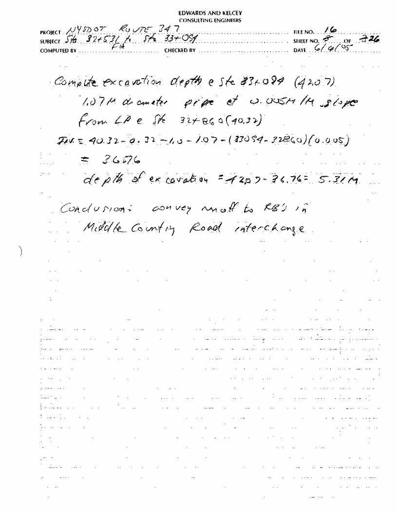
site in some watersheds some distance from the mainline low point location. Also, no candidate
RB site was identified in watershed 4 and 5, since there is no available undeveloped parcel.
Therefore, the runoff from these watersheds is conveyed to the RB’s in the Nicolls Road
interchange area in the adjacent watershed 6.
The configuration of each proposed RB was limited by the site dimensions, ground water table
elevation and topography of the candidate site. RB configuration typically used a six-meter offset
from the property line to the edge of the berm, slopes of one vertical on two horizontal, and a 4.
2-meter wide access ramp with a maximum 12 percent grade into the bottom. The bottom
typically provided a minimum fifteen-meter by ten-meter flat area.
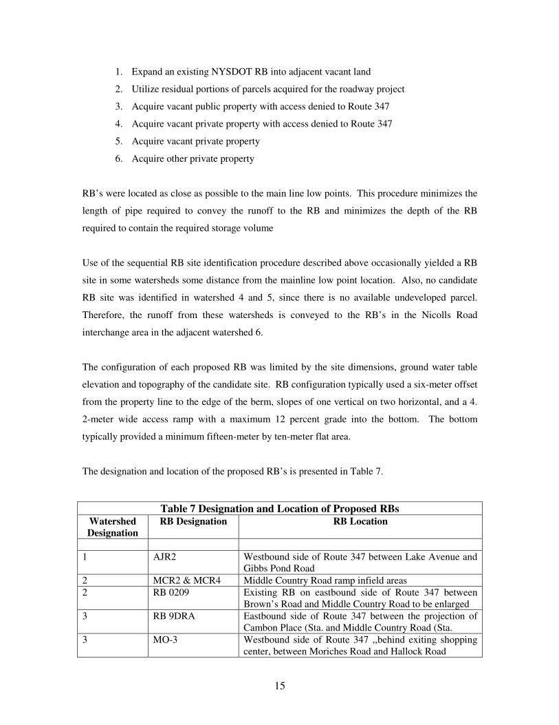
The designation and location of the proposed RB’s is presented in Table 7.
Table 7 Designation and Location of Proposed RBs Watershed Designation
RB Designation RB Location
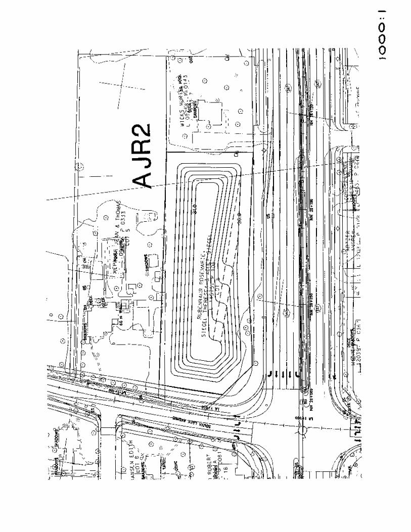
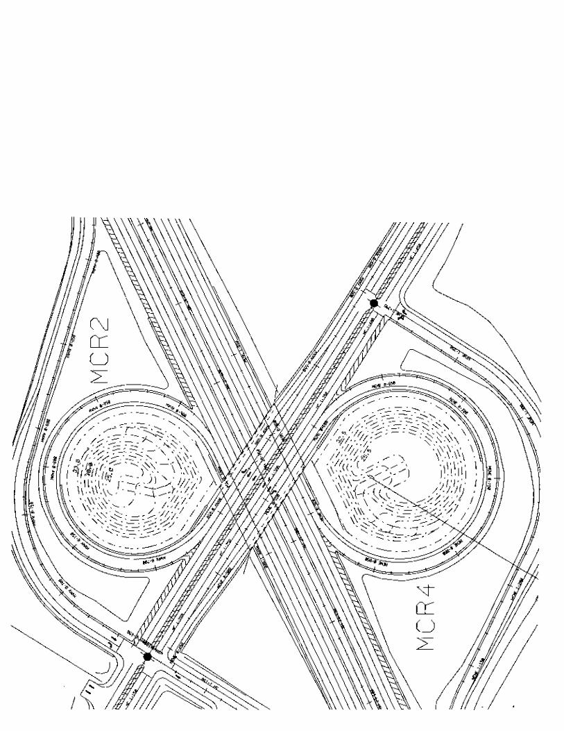
1 AJR2
Westbound side of Route 347 between Lake Avenue and Gibbs Pond Road
2 MCR2 & MCR4 Middle Country Road ramp infield areas 2 RB 0209 Existing RB on eastbound side of Route 347 between
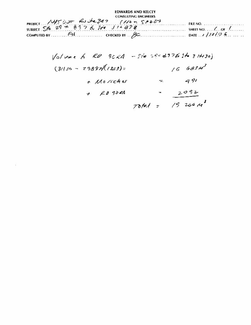
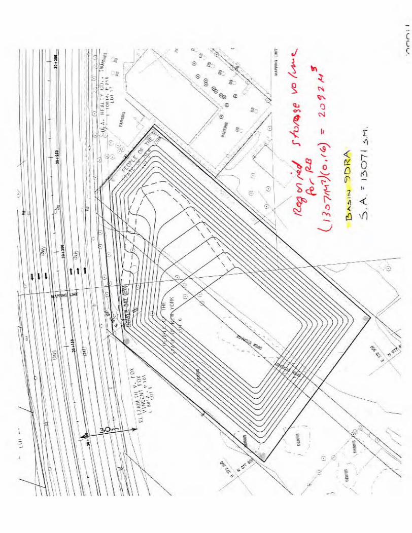
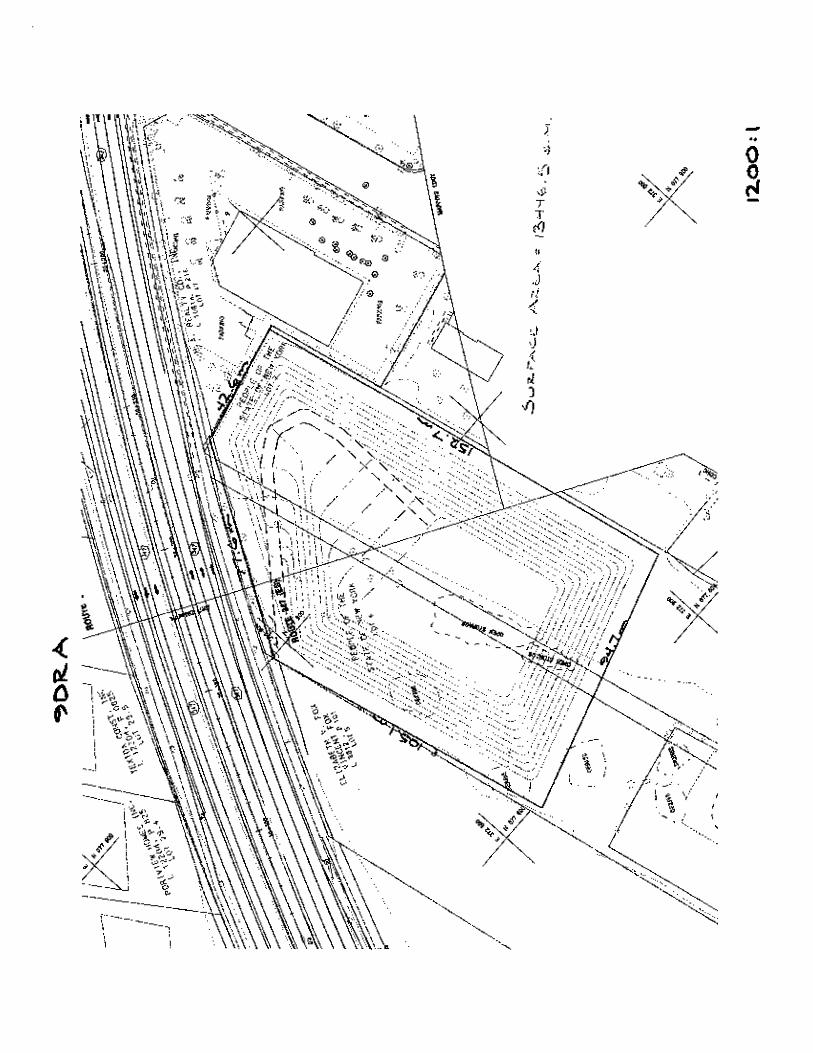
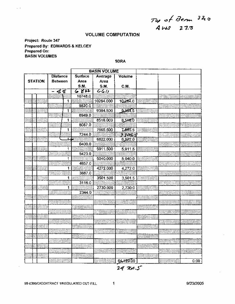
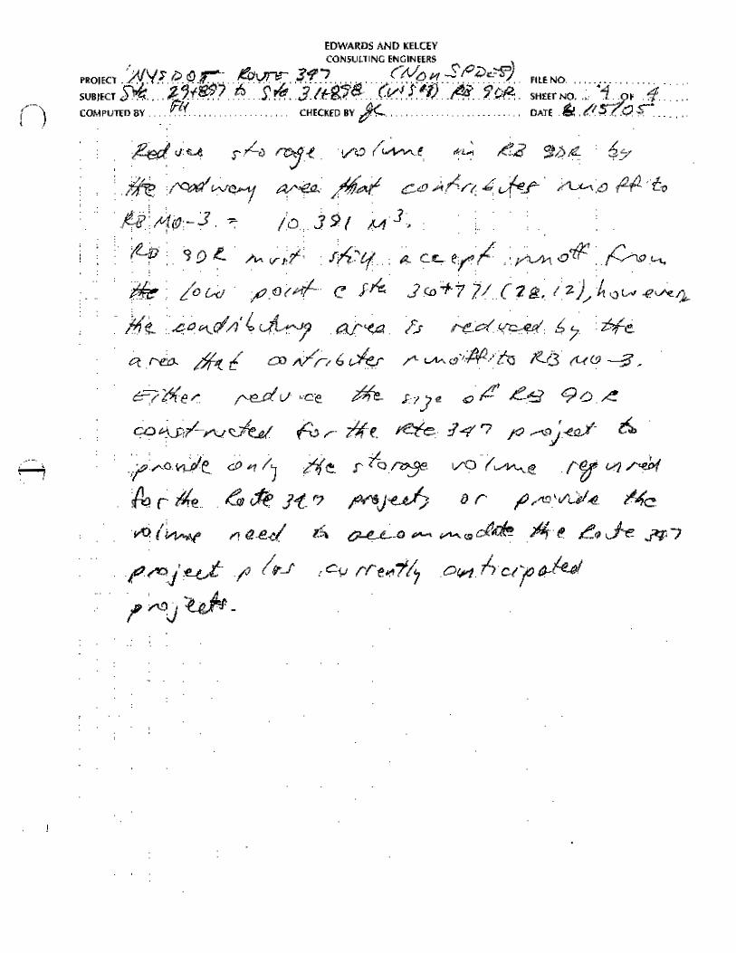
Brown’s Road and Middle Country Road to be enlarged 3 RB 9DRA Eastbound side of Route 347 between the projection of
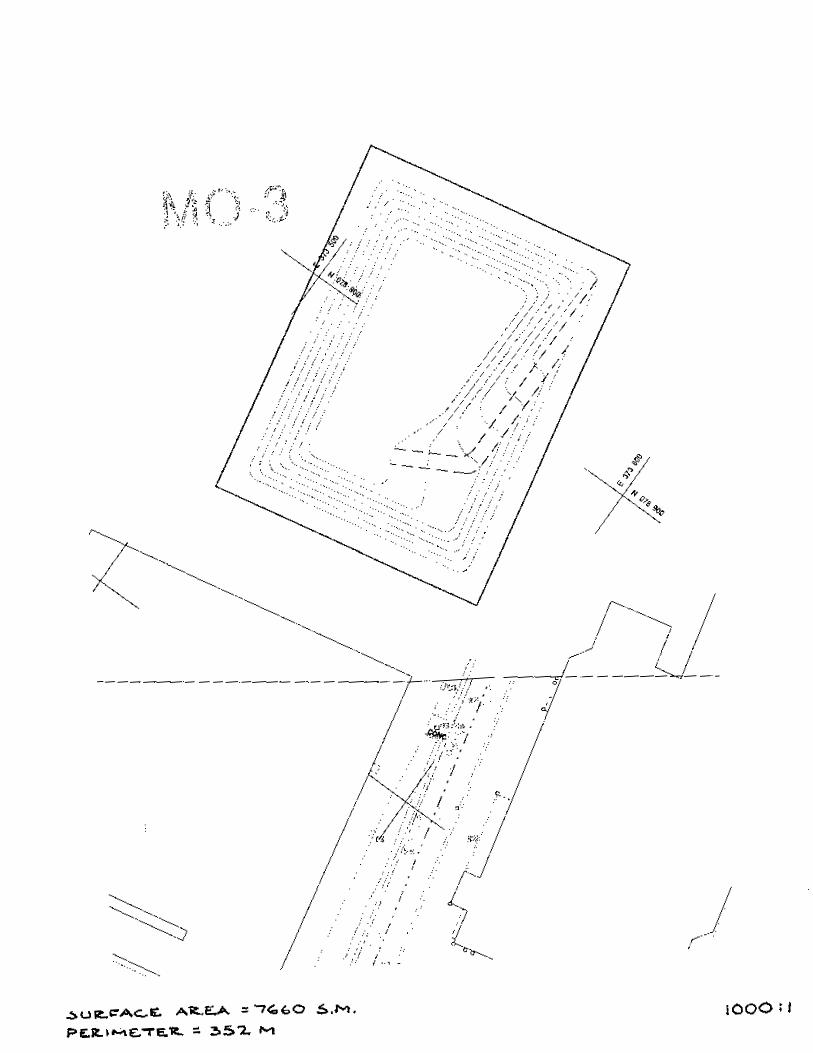
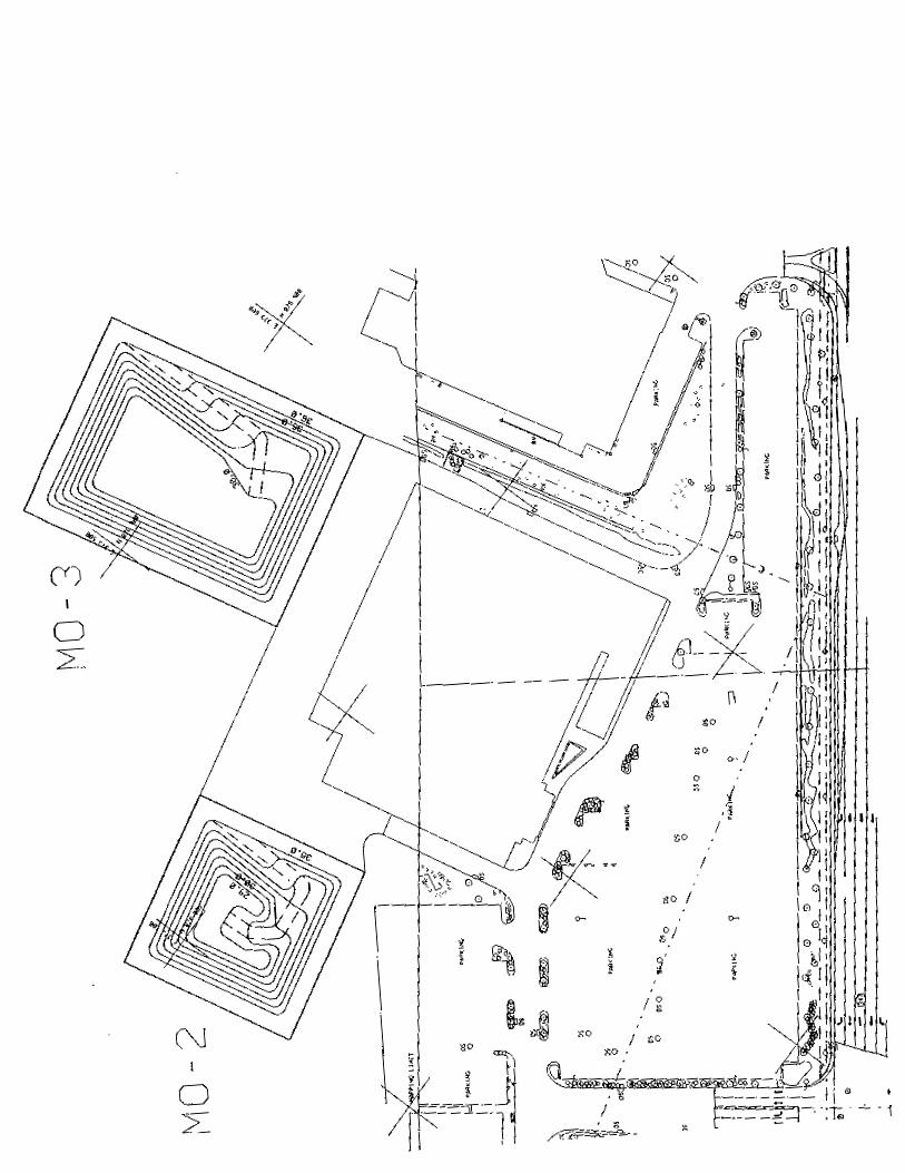
Cambon Place (Sta. and Middle Country Road (Sta. 3 MO-3 Westbound side of Route 347 ,,behind exiting shopping
center, between Moriches Road and Hallock Road
16
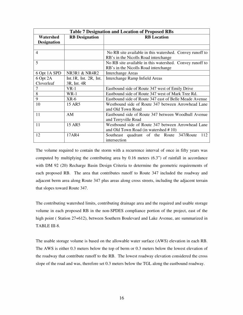
Table 7 Designation and Location of Proposed RBs Watershed Designation
RB Designation RB Location
4 No RB site available in this watershed. Convey runoff to
RB’s in the Nicolls Road interchange 5 No RB site available in this watershed. Convey runoff to
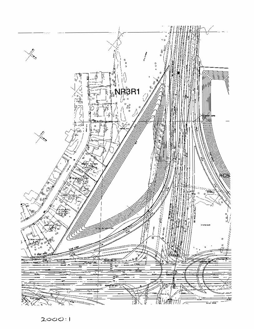
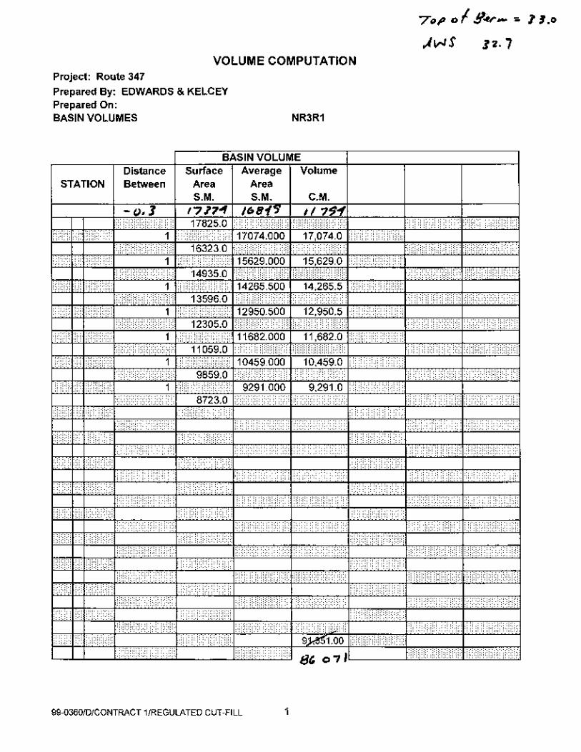
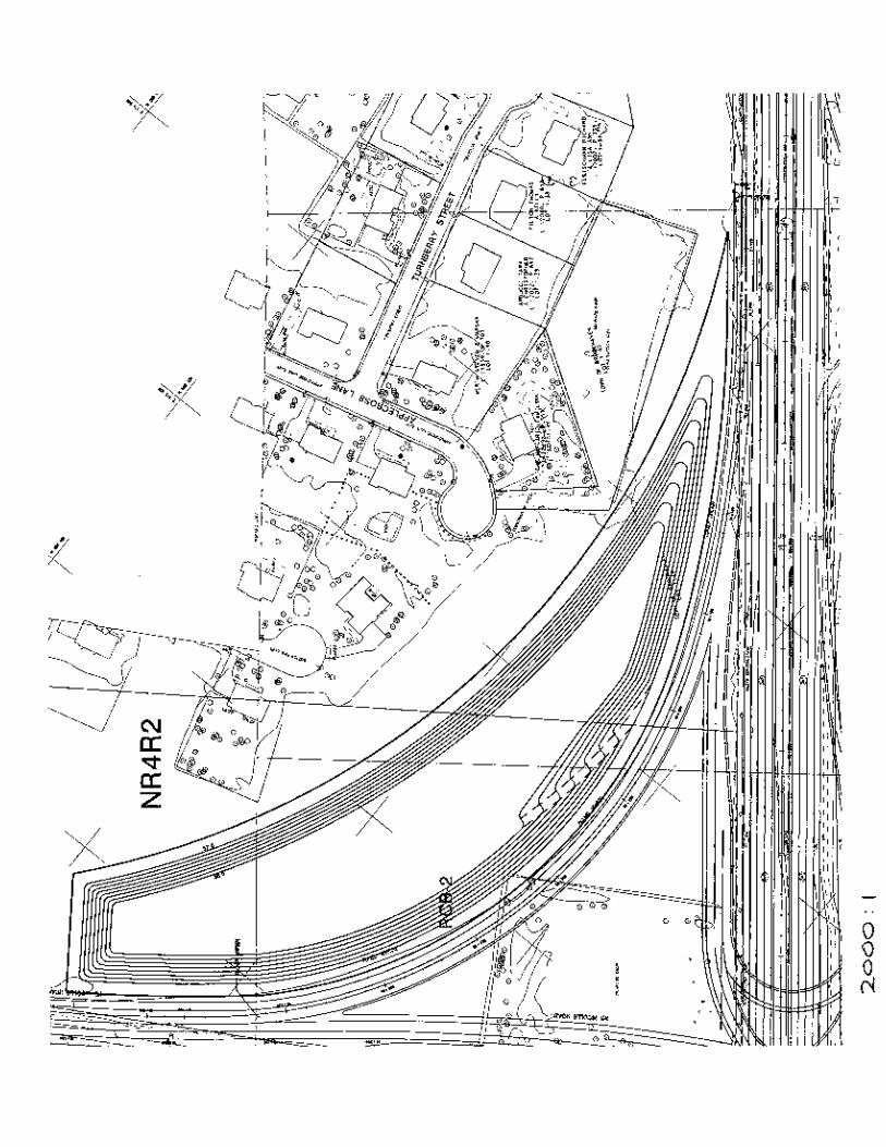
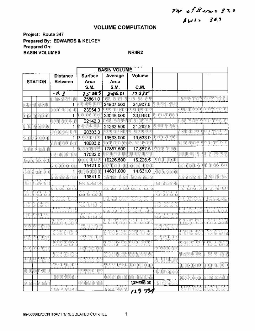
RB’s in the Nicolls Road interchange 6 Opt 1A SPD NR3R1 & NR4R2 Interchange Areas 6 Opt 2A Cloverleaf
Int.1R, Int. 2R, Int. 3R, Int. 4R
Interchange Ramp Infield Areas
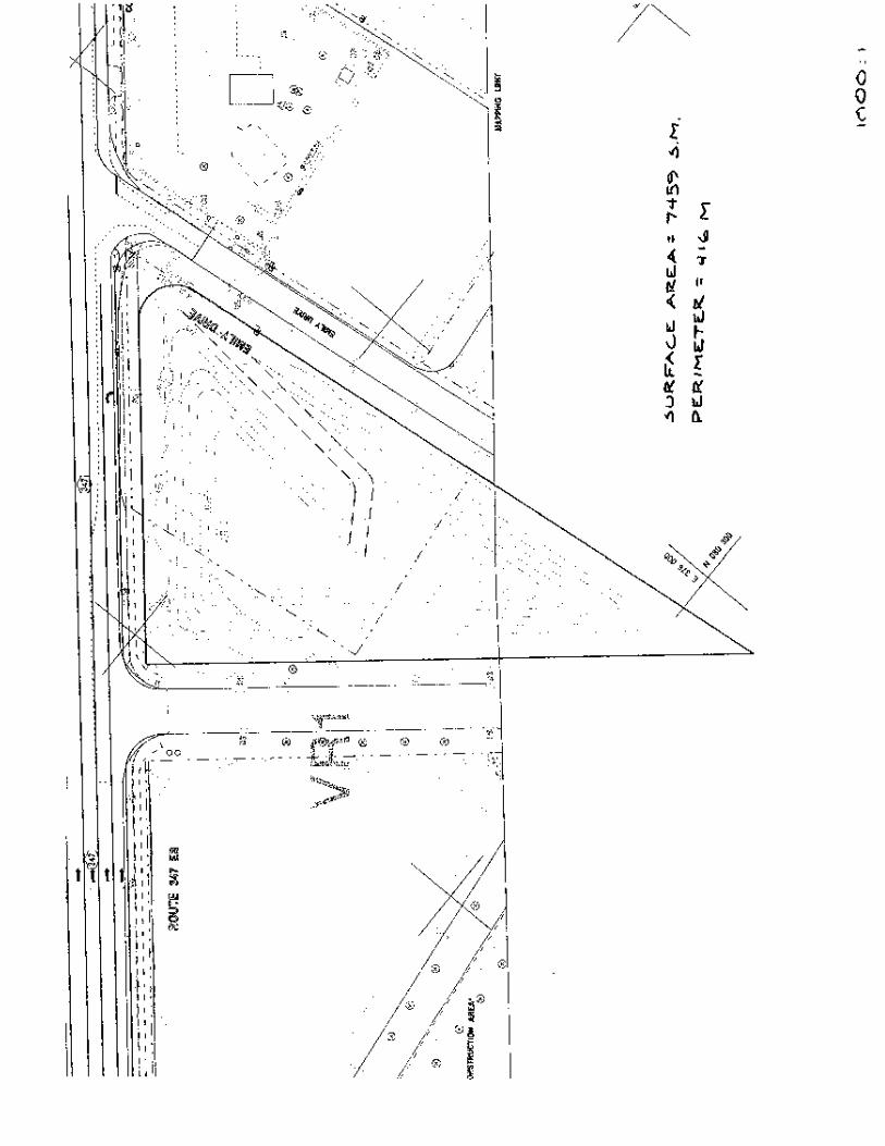
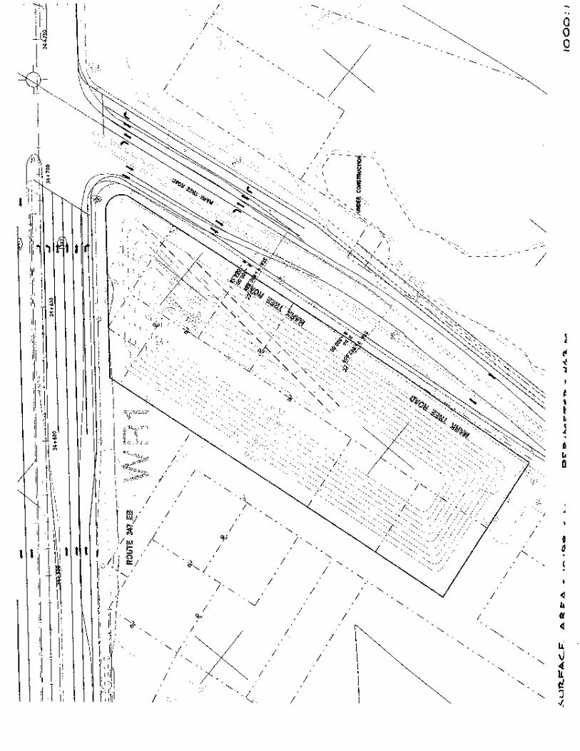
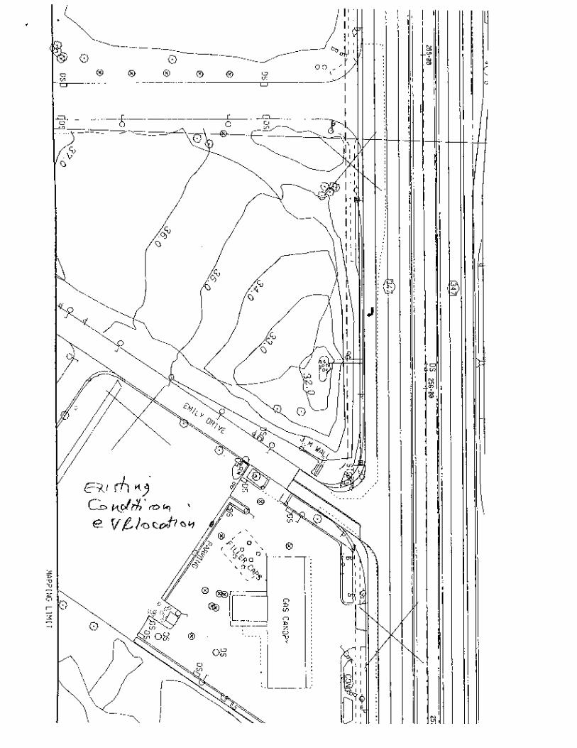
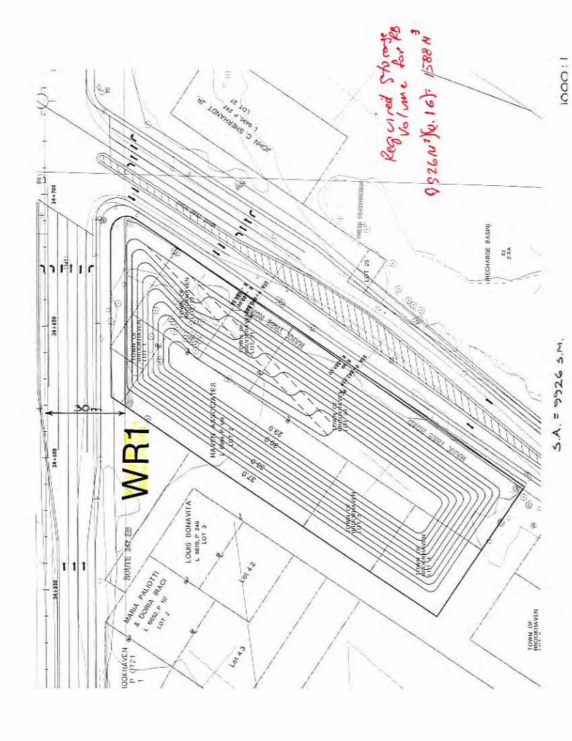
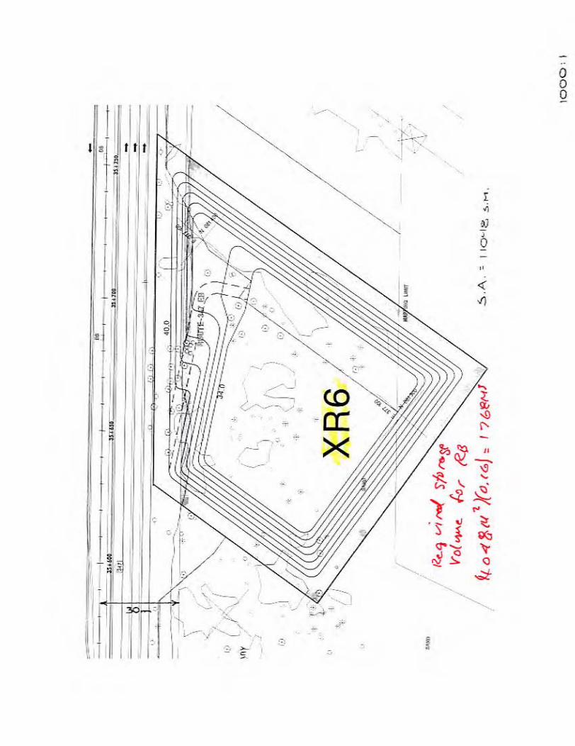
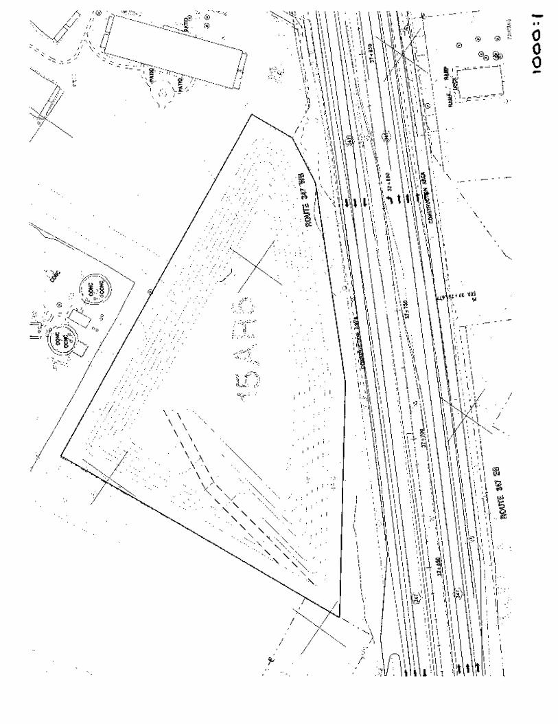
7 VR-1 Eastbound side of Route 347 west of Emily Drive 8 WR-1 Eastbound side of Route 347 west of Mark Tree Rd. 9 XR-6 Eastbound side of Route 347 east of Belle Meade Avenue 10 15 AR5 Westbound side of Route 347 between Arrowhead Lane
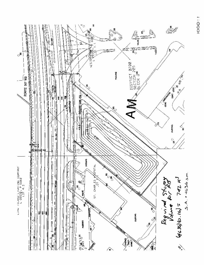
and Old Town Road 11 AM Eastbound side of Route 347 between Woodhull Avenue
and Terryville Road 11 15 AR5 Westbound side of Route 347 between Arrowhead Lane
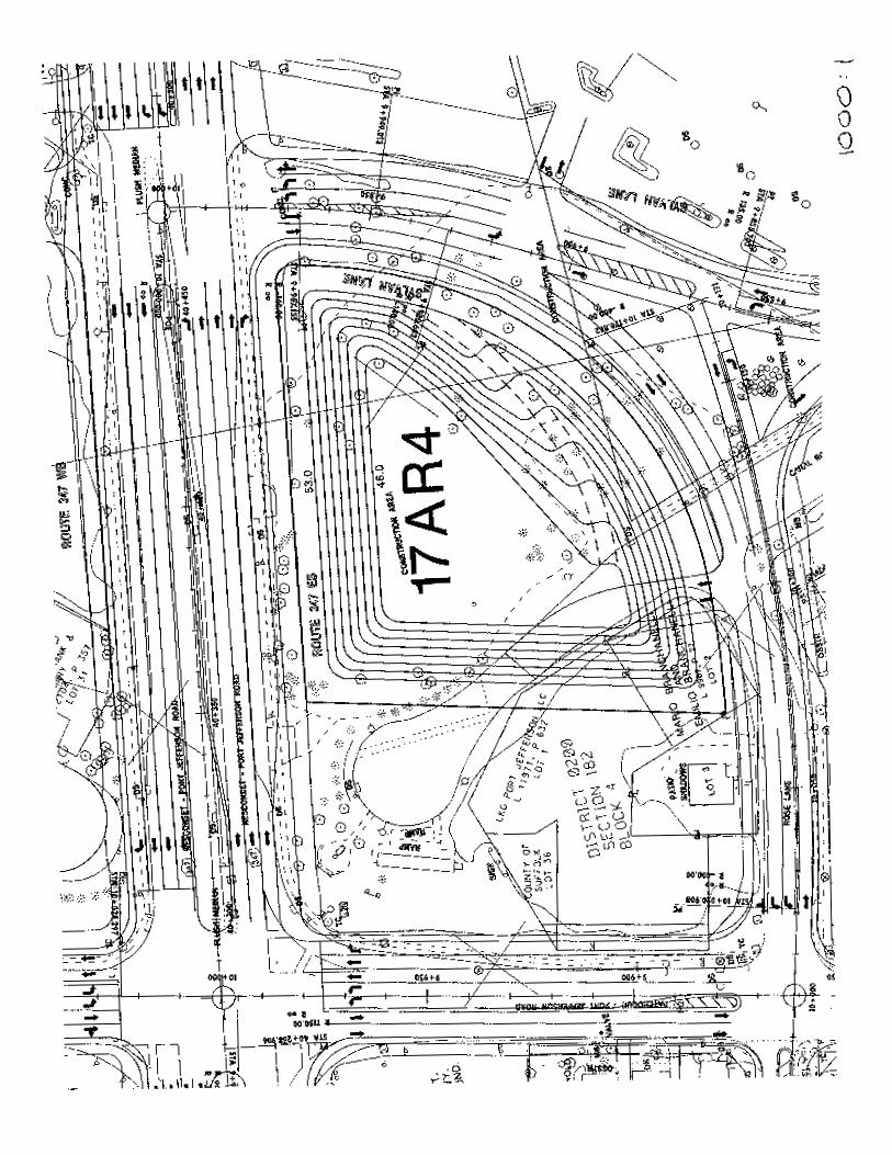
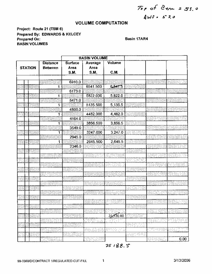
and Old Town Road (in watershed # 10) 12 17AR4 Southeast quadrant of the Route 347/Route 112
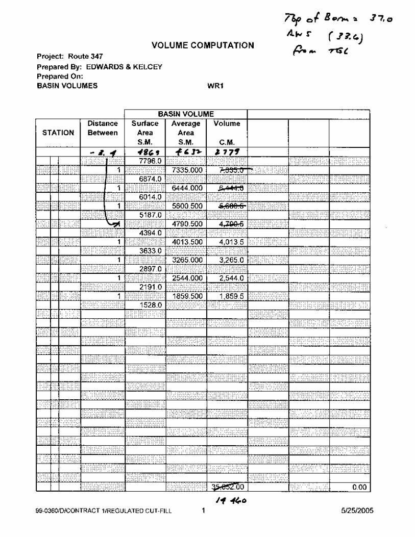
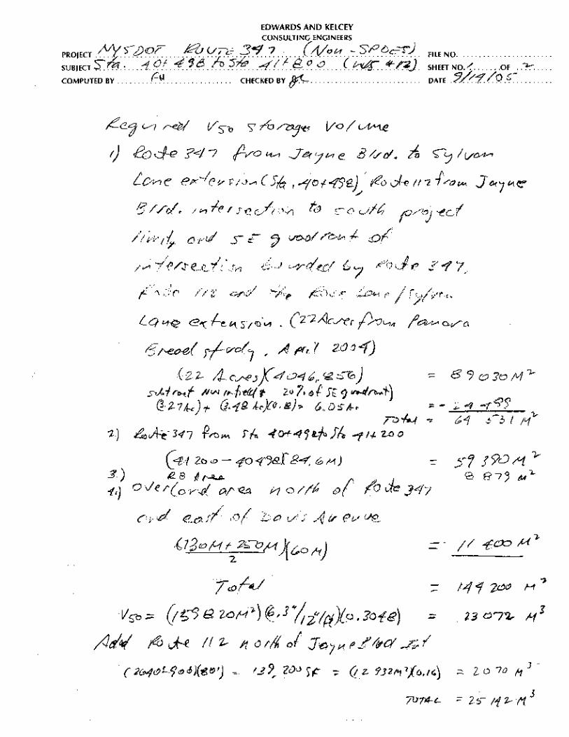
intersection The volume required to contain the storm with a recurrence interval of once in fifty years was
computed by multiplying the contributing area by 0.16 meters (6.3”) of rainfall in accordance
with DM 92 (20) Recharge Basin Design Criteria to determine the geometric requirements of
each proposed RB. The area that contributes runoff to Route 347 included the roadway and
adjacent berm area along Route 347 plus areas along cross streets, including the adjacent terrain
that slopes toward Route 347.
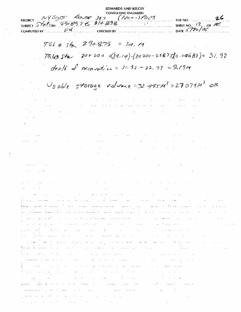
The contributing watershed limits, contributing drainage area and the required and usable storage
volume in each proposed RB in the non-SPDES compliance portion of the project, east of the
high point ( Station 27+612), between Southern Boulevard and Lake Avenue, are summarized in
TABLE III-8.
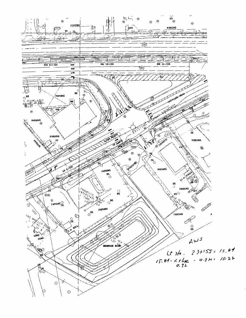
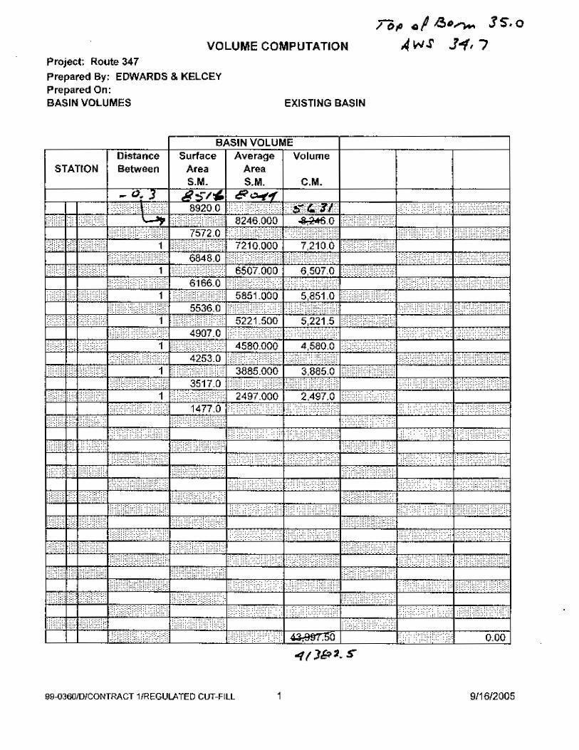
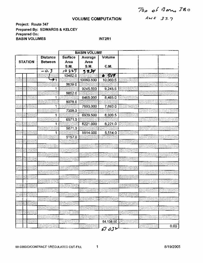
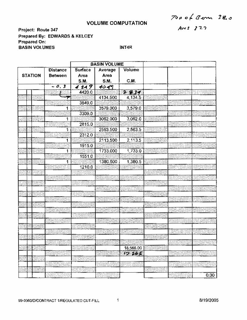
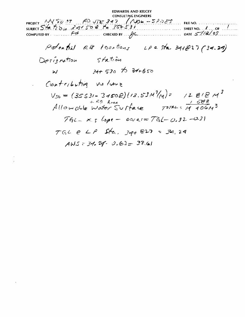
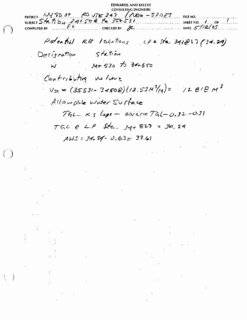
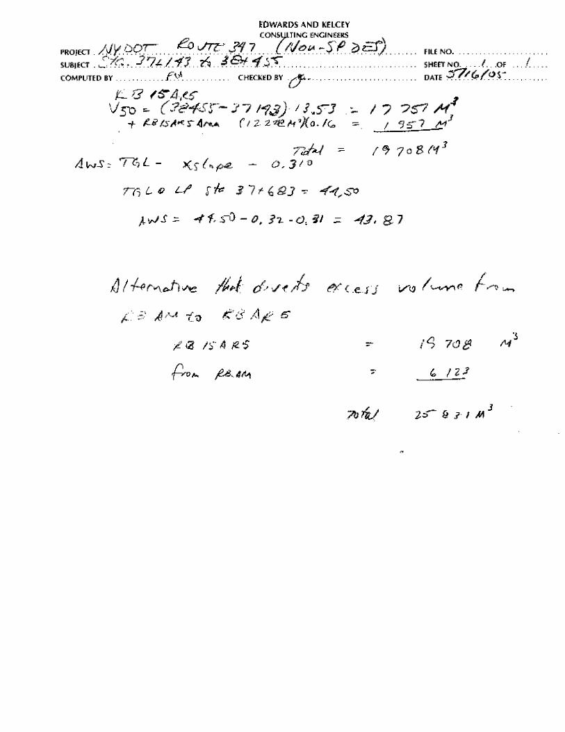
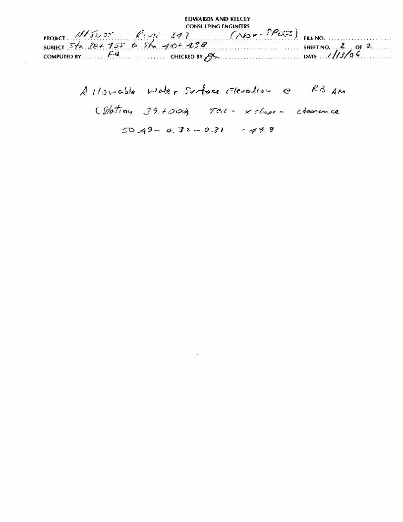
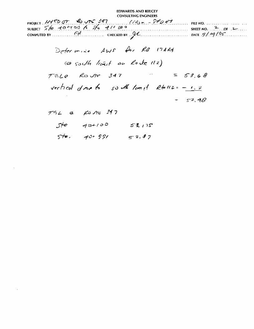
The usable storage volume is based on the allowable water surface (AWS) elevation in each RB.
The AWS is either 0.3 meters below the top of berm or 0.3 meters below the lowest elevation of
the roadway that contribute runoff to the RB. The lowest roadway elevation considered the cross
slope of the road and was, therefore set 0.3 meters below the TGL along the eastbound roadway.
17
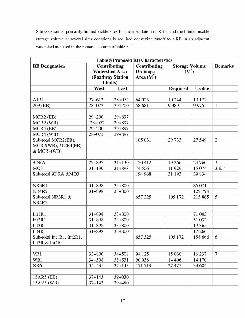
Site constraints, primarily limited viable sites for the installation of RB’s, and the limited usable
storage volume at several sites occasionally required conveying runoff to a RB in an adjacent
watershed as stated in the remarks column of table 8. T
Table 8 Proposed RB Characteristics
RB Designation Contributing Watershed Area
(Roadway Station Limits)
Contributing Drainage Area (M2)
Storage Volume (M3)
Remarks
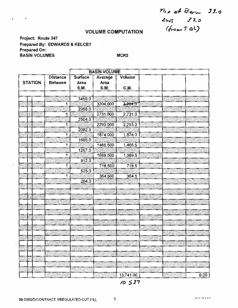
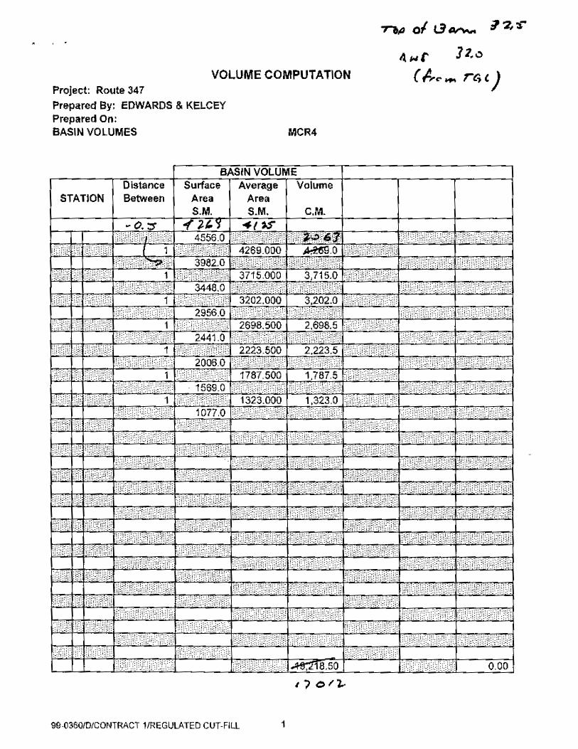
West East Required Usable AJR2 27+612 28+072 64 025 10 244 10 172 209 (EB) 28+072 29+200 58 681 9 389 9 975 1 MCR2 (EB) 29+200 29+897 MCR2 (WB) 28+072 29+897 MCR4 (EB) 29+200 29+897 MCR4 (WB) 28+072 29+897 Sub-total MCR2(EB), MCR2(WB), MCR4(EB) & MCR4(WB)
185 831 29 733 27 549 2
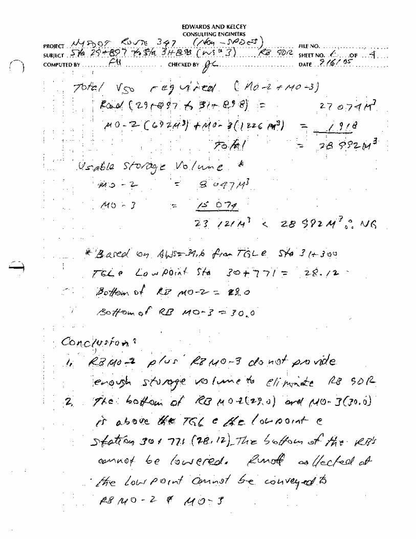
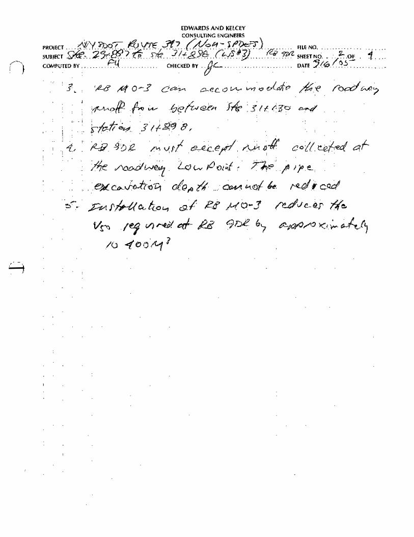
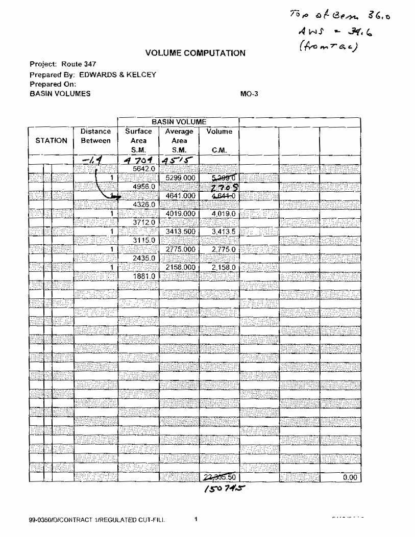
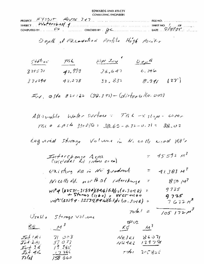
9DRA 29+897 31+130 120 412 19 266 24 760 3 MO3 31+130 31+898 74 556 11 929 15 074 3 & 4 Sub-total 9DRA &MO3 194 968 31 193 39 834 NR3R1 31+898 33+800 86 071 NR4R2 31+898 33+800 129 794 Sub-total NR3R1 & NR4R2
657 325 105 172 215 865 5
Int1R1 31+898 33+800 71 003 Int2R1 31+898 33+800 51 032 Int3R 31+898 33+800 19 365 Int4R 31+898 33+800 17 266 Sub-total Int1R1, Int2R1, Int3R & Int4R
657 325 105 172 158 666 6
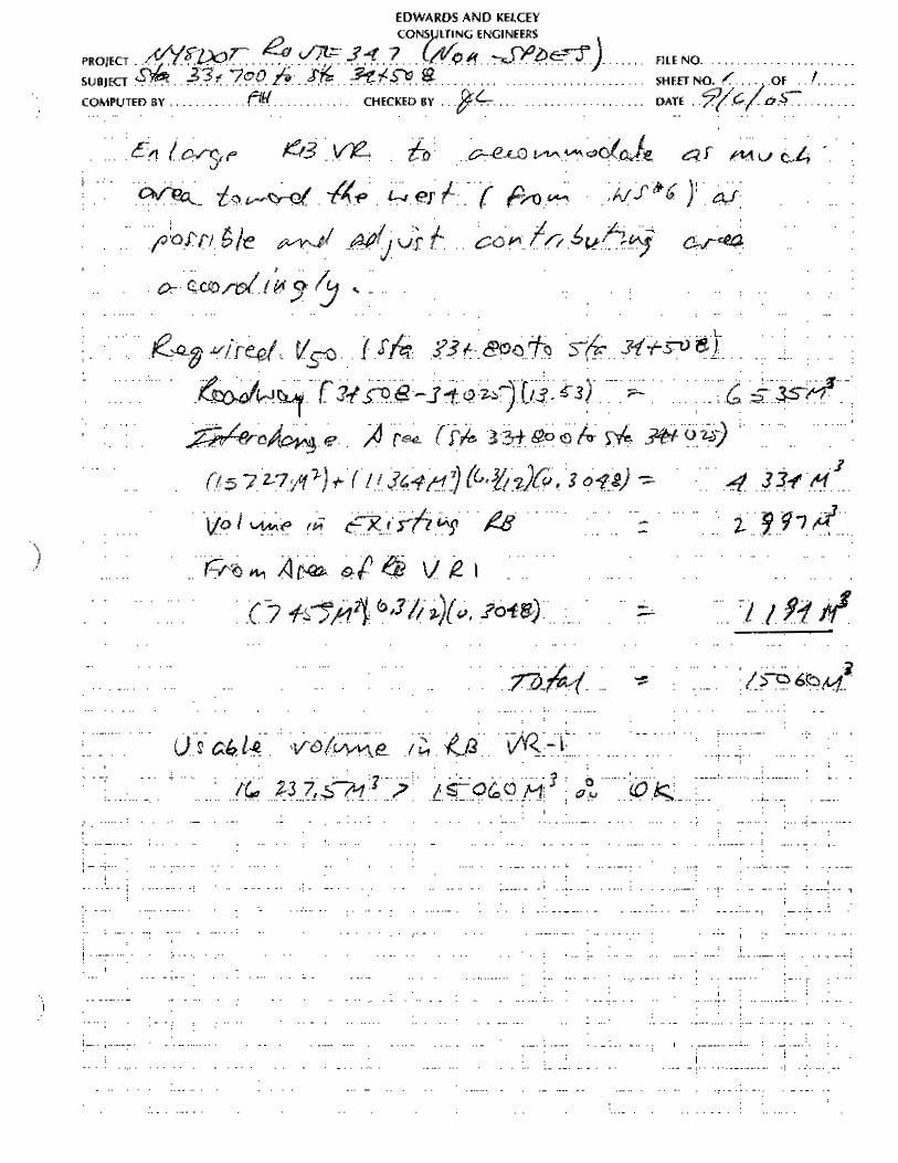
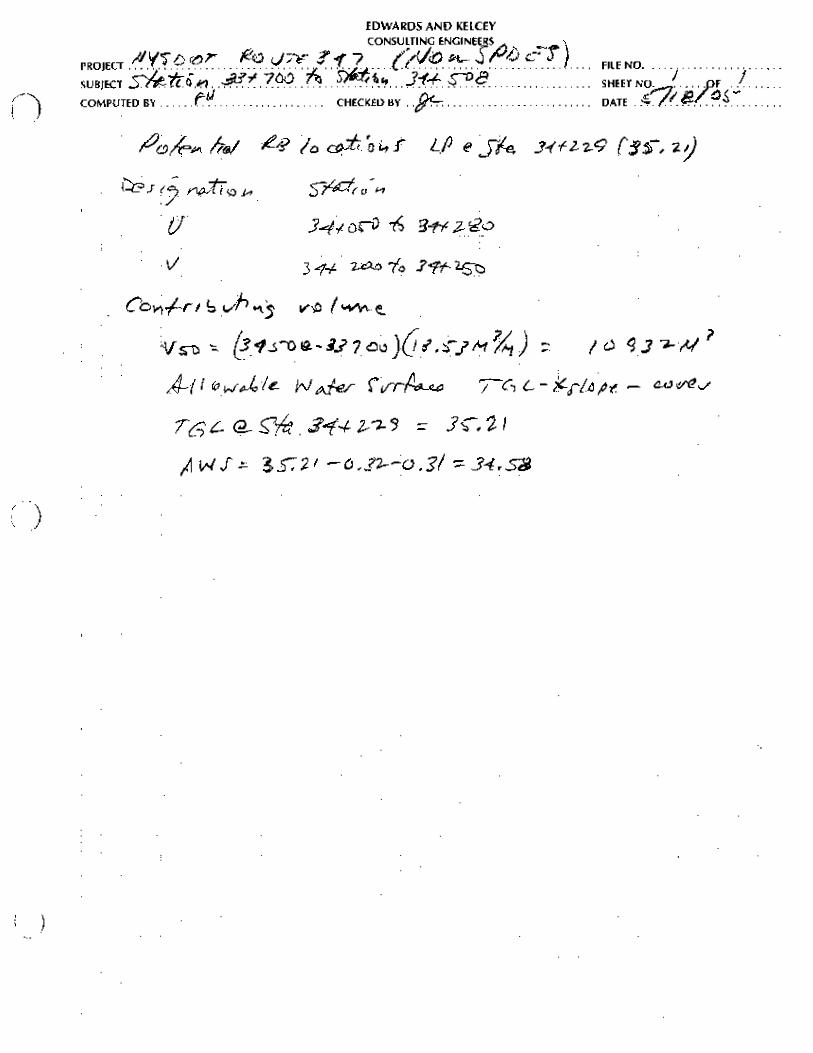
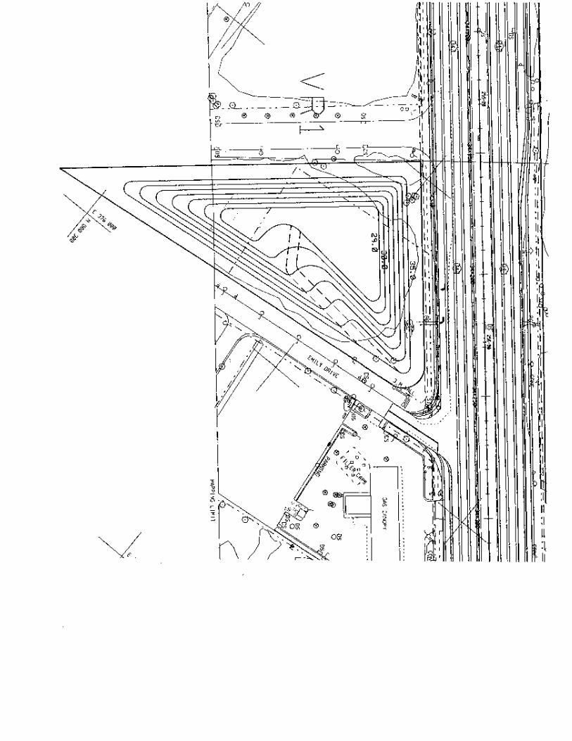
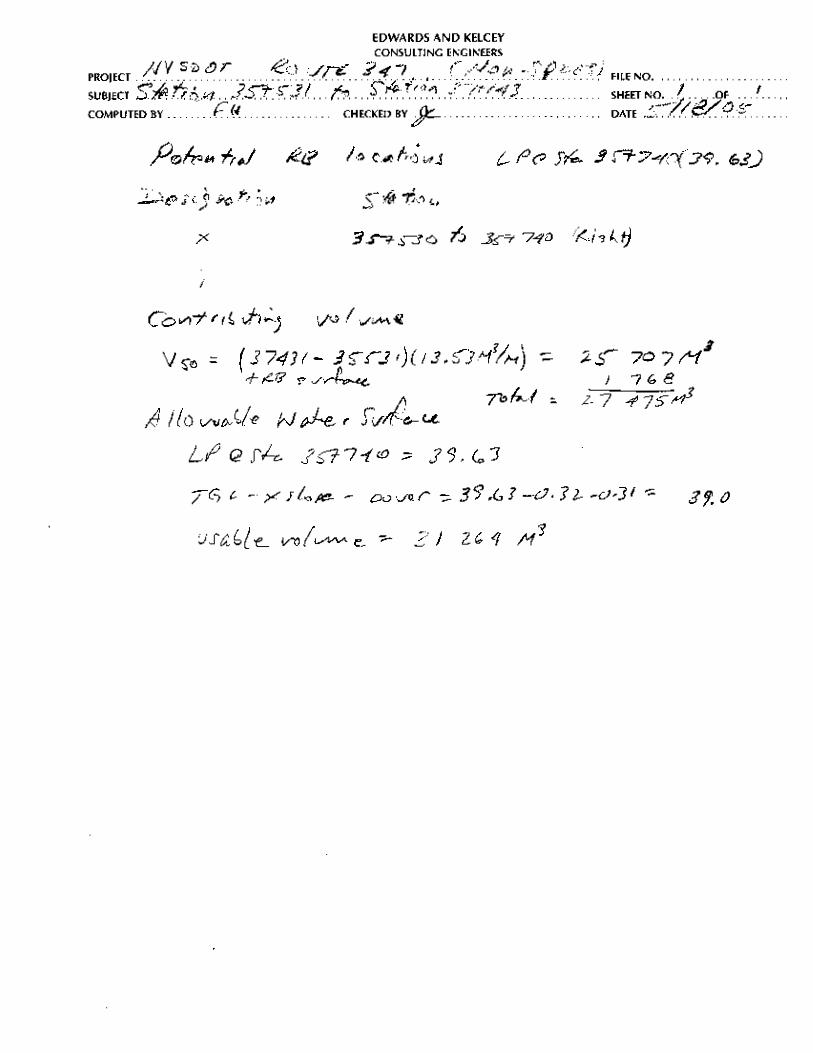
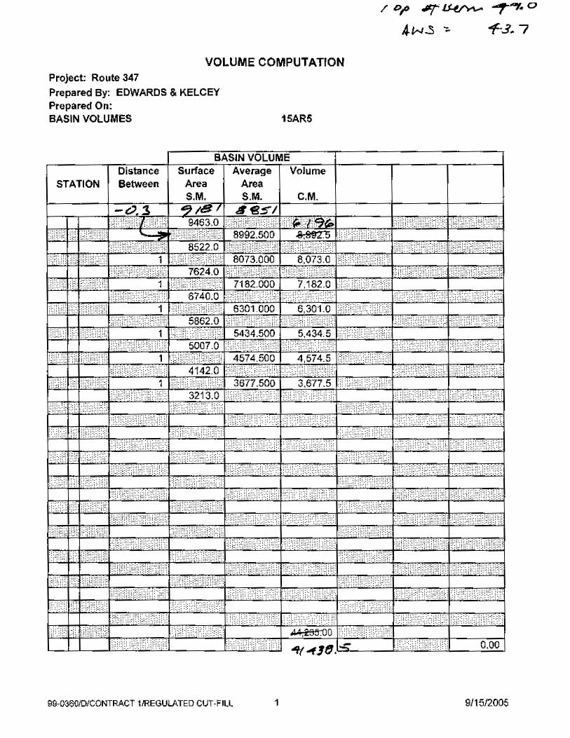
VR1 33+800 34+508 94 125 15 060 16 237 7 WR1 34+508 35+531 90 038 14 406 14 170 XR6 35+531 37+143 171 719 27 475 33 684 15AR5 (EB) 37+143 39+030 15AR5 (WB) 37+143 39+480
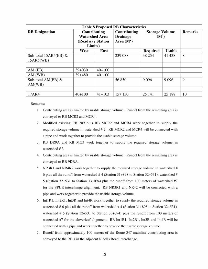
18
Table 8 Proposed RB Characteristics RB Designation Contributing
Watershed Area (Roadway Station
Limits)
Contributing Drainage Area (M2)
Storage Volume (M3)
Remarks
West East Required Usable Sub-total 15AR5(EB) & 15AR5(WB)
239 088 38 254 41 438 8
AM (EB) 39+030 40+100 AM (WB) 39+480 40+100 Sub-total AM(EB) & AM(WB)
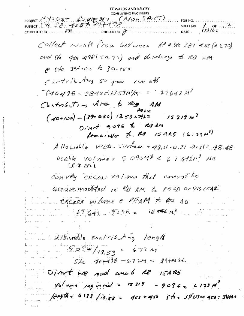
56 850 9 096 9 096 9
17AR4 40+100 41+103 157 130 25 141 25 188 10
Remarks:
1. Contributing area is limited by usable storage volume. Runoff from the remaining area is
conveyed to RB MCR2 and MCR4.
2. Modified existing RB 209 plus RB MCR2 and MCR4 work together to supply the
required storage volume in watershed # 2. RB MCR2 and MCR4 will be connected with
a pipe and work together to provide the usable storage volume.
3. RB DR9A and RB MO3 work together to supply the required storage volume in
watershed # 3
4. Contributing area is limited by usable storage volume. Runoff from the remaining area is
conveyed to RB 9DRA.
5. NR3R1 and NR4R2 work together to supply the required storage volume in watershed #
6 plus all the runoff from watershed # 4 (Station 31+898 to Station 32+531), watershed #
5 (Station 32+531 to Station 33+094) plus the runoff from 100 meters of watershed #7
for the SPUE interchange alignment. RB NR3R1 and NR42 will be connected with a
pipe and work together to provide the usable storage volume.
6. Int1R1, Int2R1, Int3R and Int4R work together to supply the required storage volume in
watershed # 6 plus all the runoff from watershed # 4 (Station 31+898 to Station 32+531),
watershed # 5 (Station 32+531 to Station 33+094) plus the runoff from 100 meters of
watershed #7 for the cloverleaf alignment. RB Int1R1, Int2R1, Int3R and Int4R will be
connected with a pipe and work together to provide the usable storage volume.
7. Runoff from approximately 100 meters of the Route 347 mainline contributing area is
conveyed to the RB’s in the adjacent Nicolls Road interchange.
19
8. Accommodates runoff from the portion of the adjacent watershed # 11for which storage
volume cannot be a provided in RB AM.
9. Contributing area is limited by usable storage volume. Runoff from the remaining area is
conveyed to RB 15AR5.
10. Accepts runoff from portions of watershed # 11 and watershed # 12. Contributing runoff
area limits along Route 347 are from the west side of Jayne Boulevard (at approximately
Station 40+100) to the highpoint at approximately Station 401+103.
Stormwater Management Maps are in Appendix E
Roadway Runoff Collection and Conveyance System
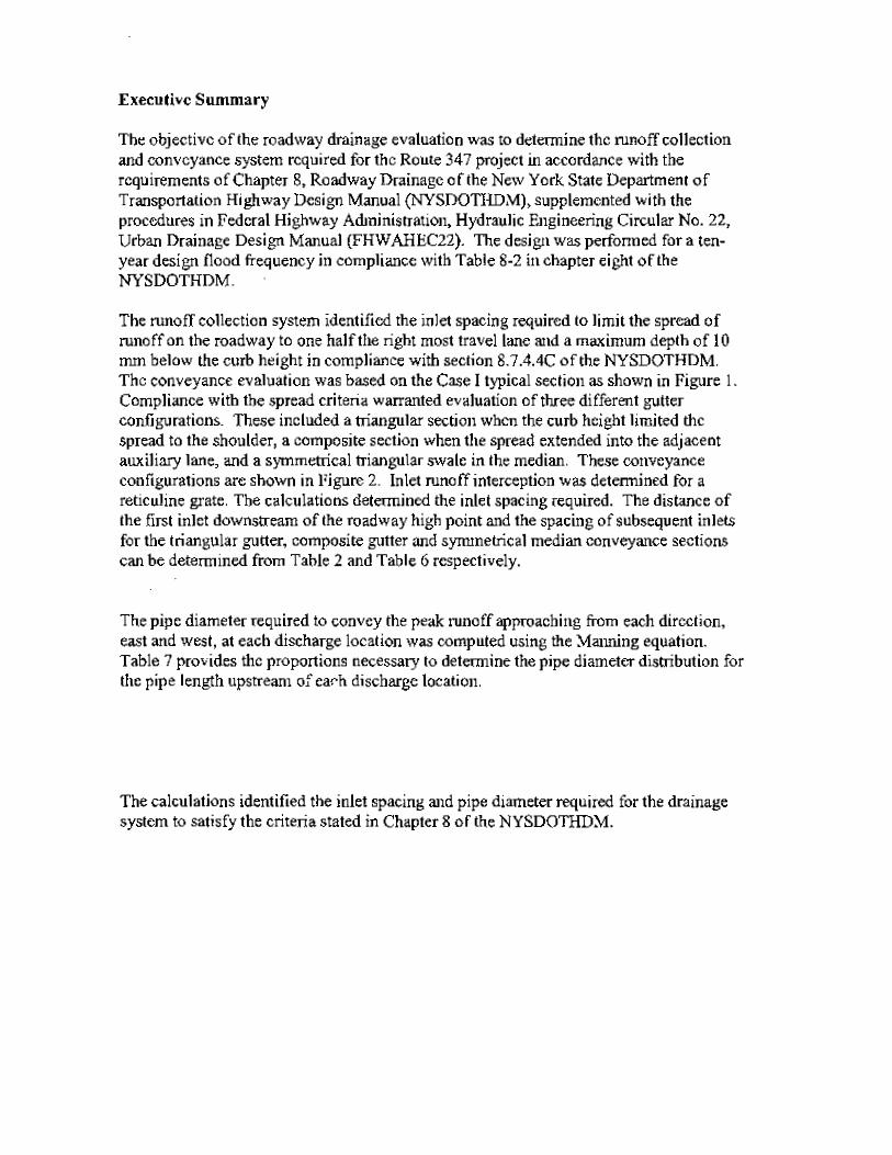
The objective of the roadway drainage evaluation was to determine the runoff collection and
conveyance system required for the Route 347 project in accordance with the requirements of
Chapter 8, Roadway Drainage of the HDM (HDM), supplemented with the procedures in
Federal Highway Administration, Hydraulic Engineering Circular No. 22, Urban Drainage
Design Manual (HEC22). The design was performed for a ten-year design flood frequency in
compliance with Table 8-2 in Chapter 8 of the HDM.
Inlet runoff interception and spacing and pipe diameters are each discussed separately in the
following narrative.
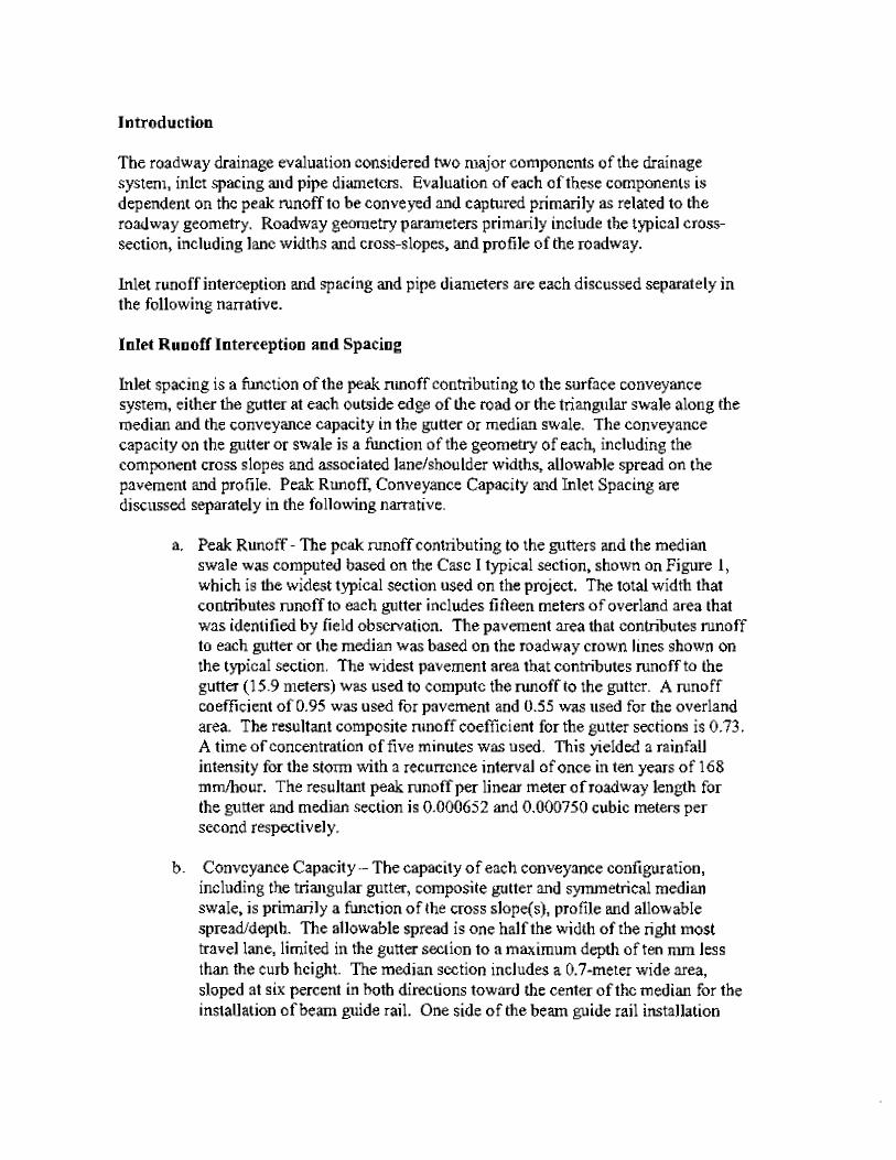
Inlet Runoff Interception and Spacing
Inlet spacing is a function of the peak runoff contributing to the surface conveyance system,
either the gutter at each outside edge of the road or the triangular swale along the median and the
conveyance capacity in the gutter or median swale. The conveyance capacity on the gutter or
swale is a function of the geometry of each, including the component cross slopes and associated
lane/shoulder widths, allowable spread on the pavement and profile. Peak Runoff, Conveyance
Capacity and Inlet Spacing are discussed separately in the following narrative.
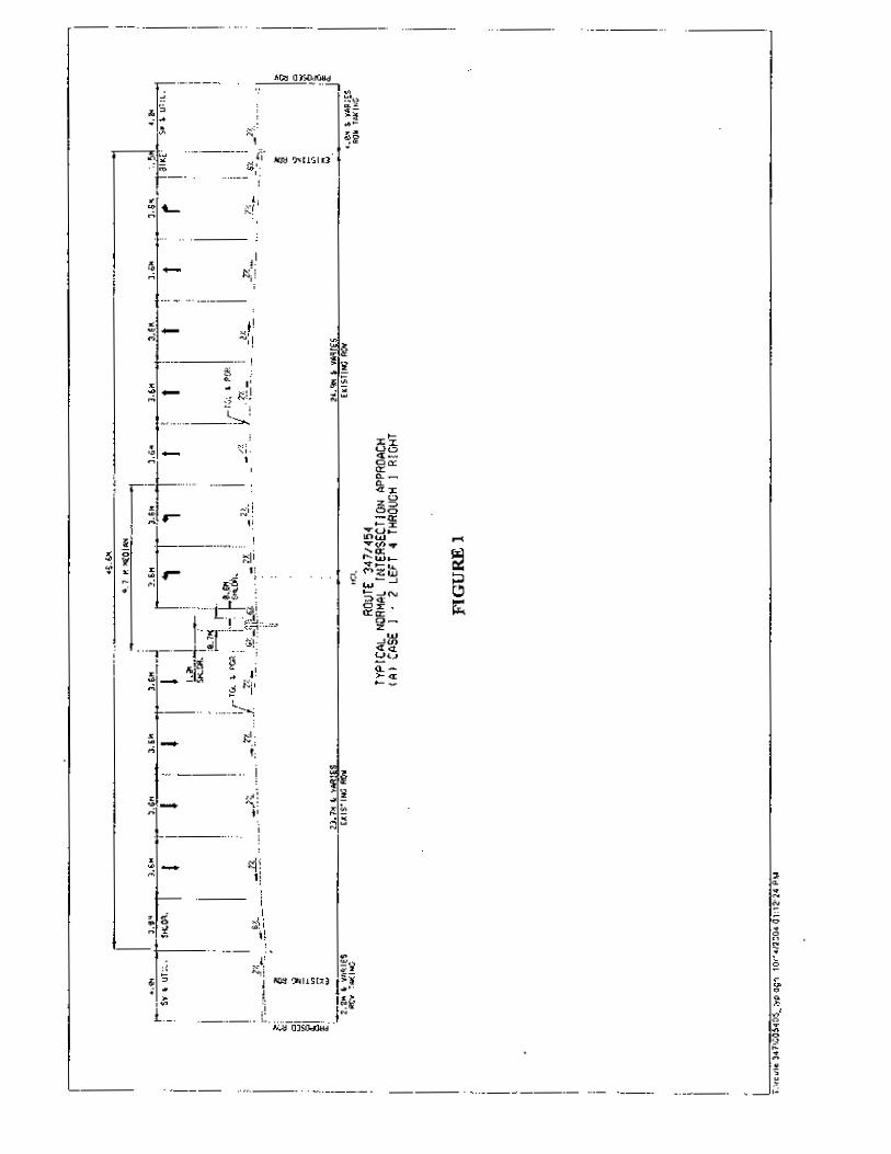
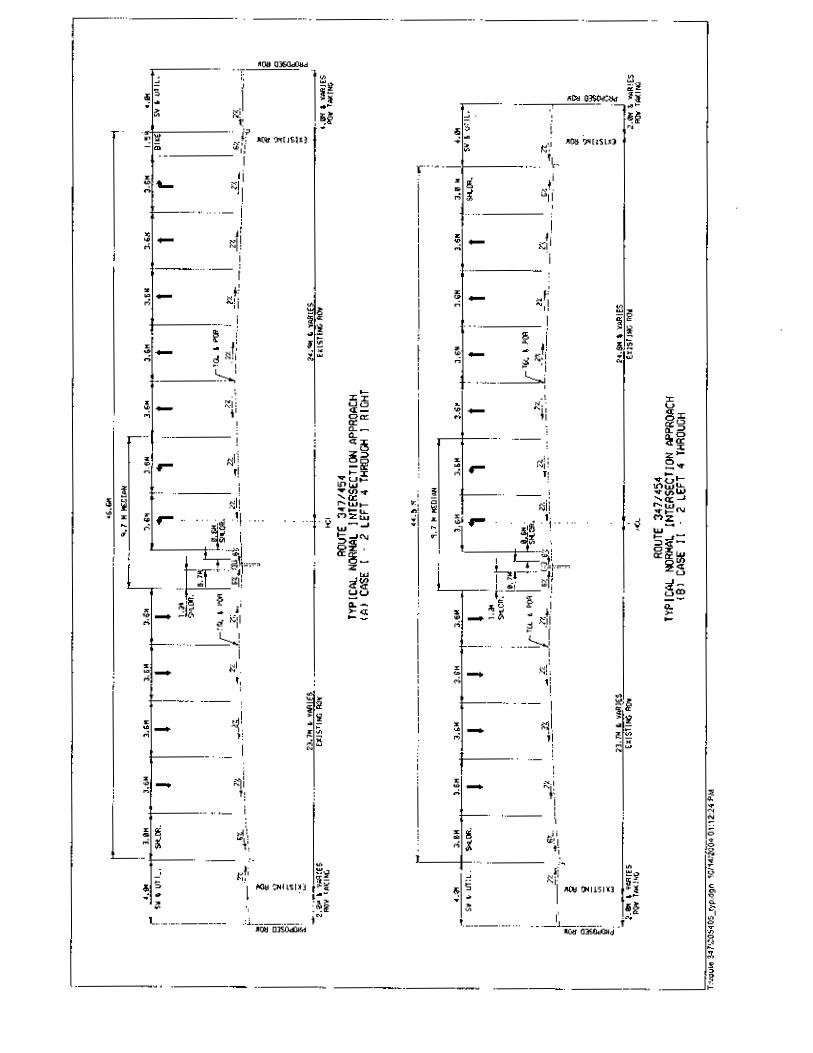
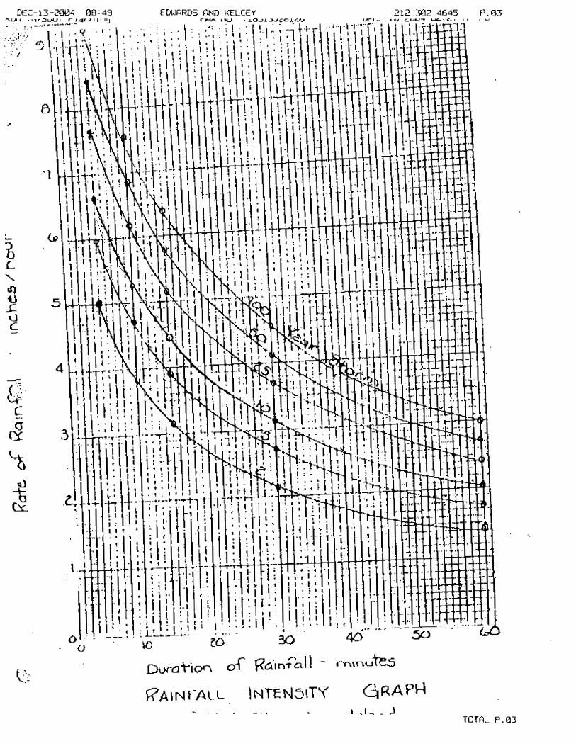
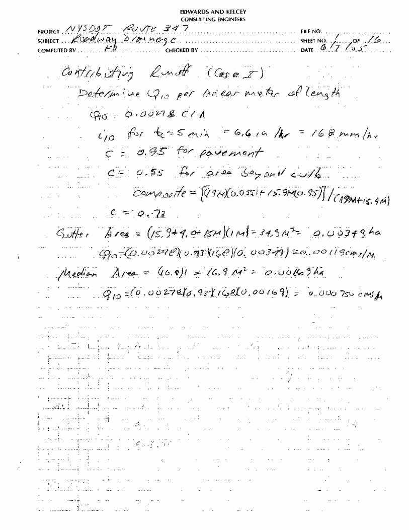
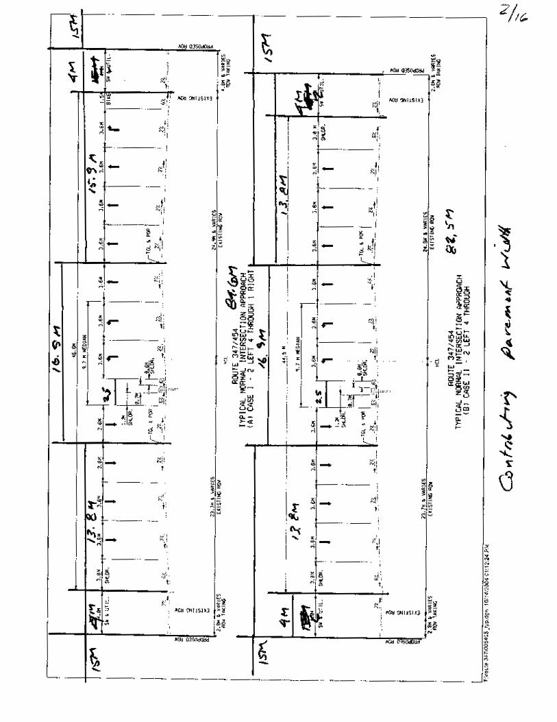
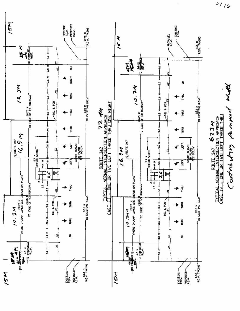
a. Peak Runoff - The peak runoff contributing to the gutters and the median swale was
computed based on the Case I typical section, which is the widest typical section used
on the project. The total width that contributes runoff to each gutter includes fifteen
20
meters of overland area that was identified by field observation. The pavement area
that contributes runoff to each gutter or the median was based on the roadway crown
lines shown on the typical section. The widest pavement area that contributes runoff
to the gutter (15.9 meters) was used to compute the runoff to the gutter. A runoff
coefficient of 0.95 was used for pavement and 0.55 was used for the overland area.
The resultant composite runoff coefficient for the gutter sections is 0.73. A time of
concentration of five minutes was used. This yielded a rainfall intensity for the storm
with a recurrence interval of once in ten years of 168 mm/hour. The resultant peak
runoff per linear meter of roadway length for the gutter and median section is
0.000652 and 0.000750 cubic meters per second respectively.
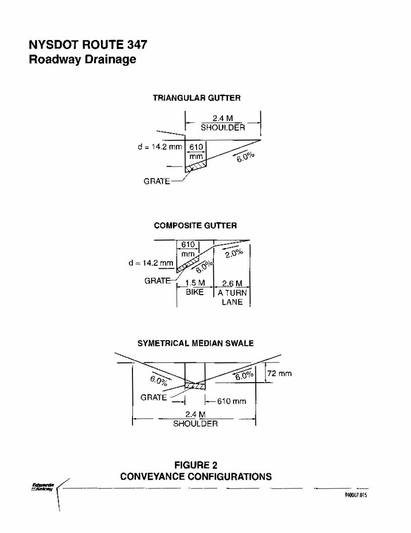
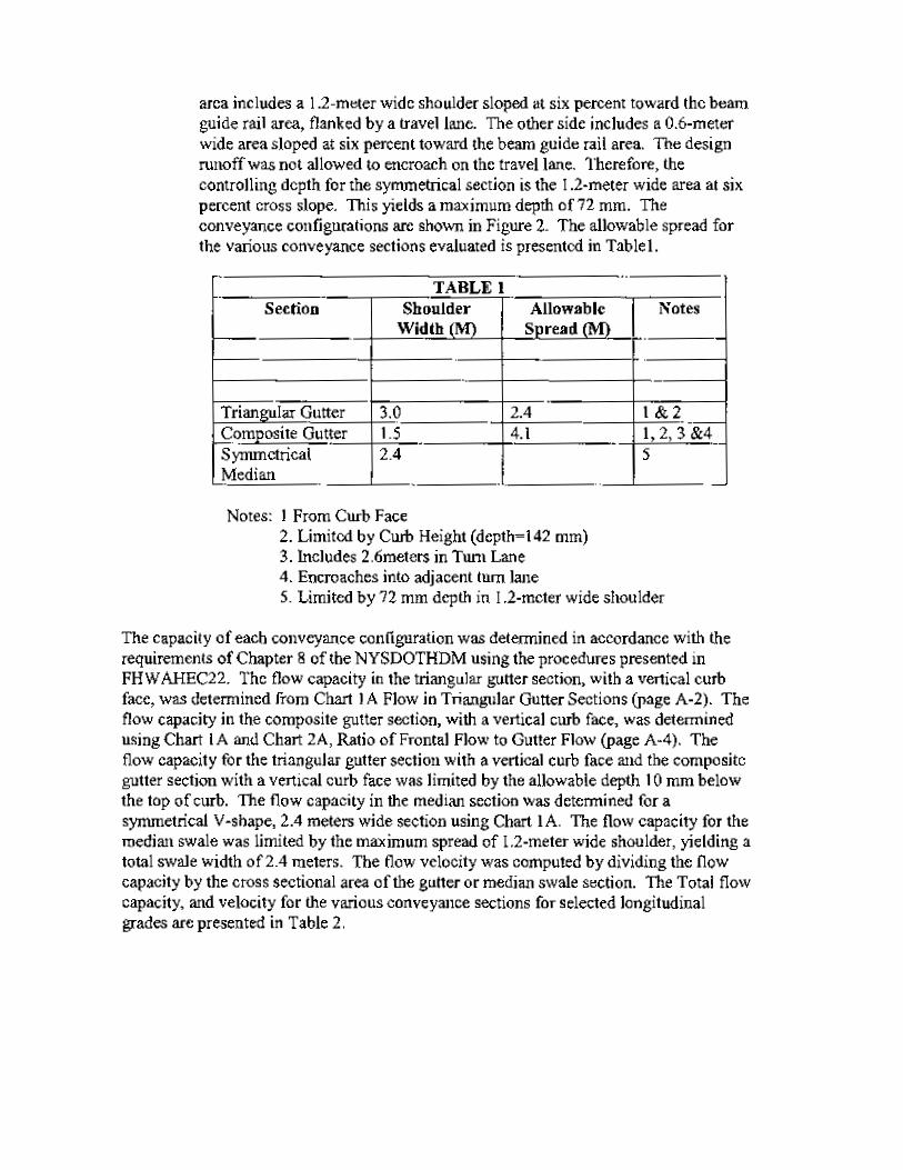
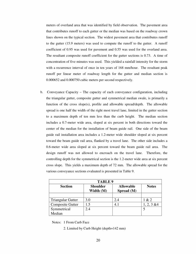
b. Conveyance Capacity – The capacity of each conveyance configuration, including
the triangular gutter, composite gutter and symmetrical median swale, is primarily a
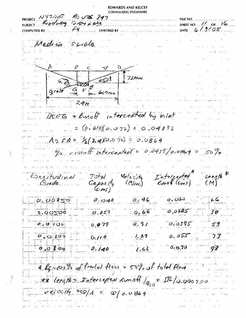
function of the cross slope(s), profile and allowable spread/depth. The allowable
spread is one half the width of the right most travel lane, limited in the gutter section
to a maximum depth of ten mm less than the curb height. The median section
includes a 0.7-meter wide area, sloped at six percent in both directions toward the
center of the median for the installation of beam guide rail. One side of the beam
guide rail installation area includes a 1.2-meter wide shoulder sloped at six percent
toward the beam guide rail area, flanked by a travel lane. The other side includes a
0.6-meter wide area sloped at six percent toward the beam guide rail area. The
design runoff was not allowed to encroach on the travel lane. Therefore, the
controlling depth for the symmetrical section is the 1.2-meter wide area at six percent
cross slope. This yields a maximum depth of 72 mm. The allowable spread for the
various conveyance sections evaluated is presented in Table 9.
TABLE 9
Section Shoulder Width (M)
Allowable Spread (M)
Notes
Triangular Gutter 3.0 2.4 1 & 2 Composite Gutter 1.5 4.1 1, 2, 3 &4 Symmetrical Median
2.4 5
Notes: 1 From Curb Face
2. Limited by Curb Height (depth=142 mm)
21
3. Includes 2.6meters in Turn Lane
4. Encroaches into adjacent turn lane
5. Limited by 72 mm depth in 1.2-meter wide shoulder
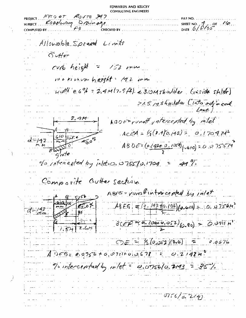
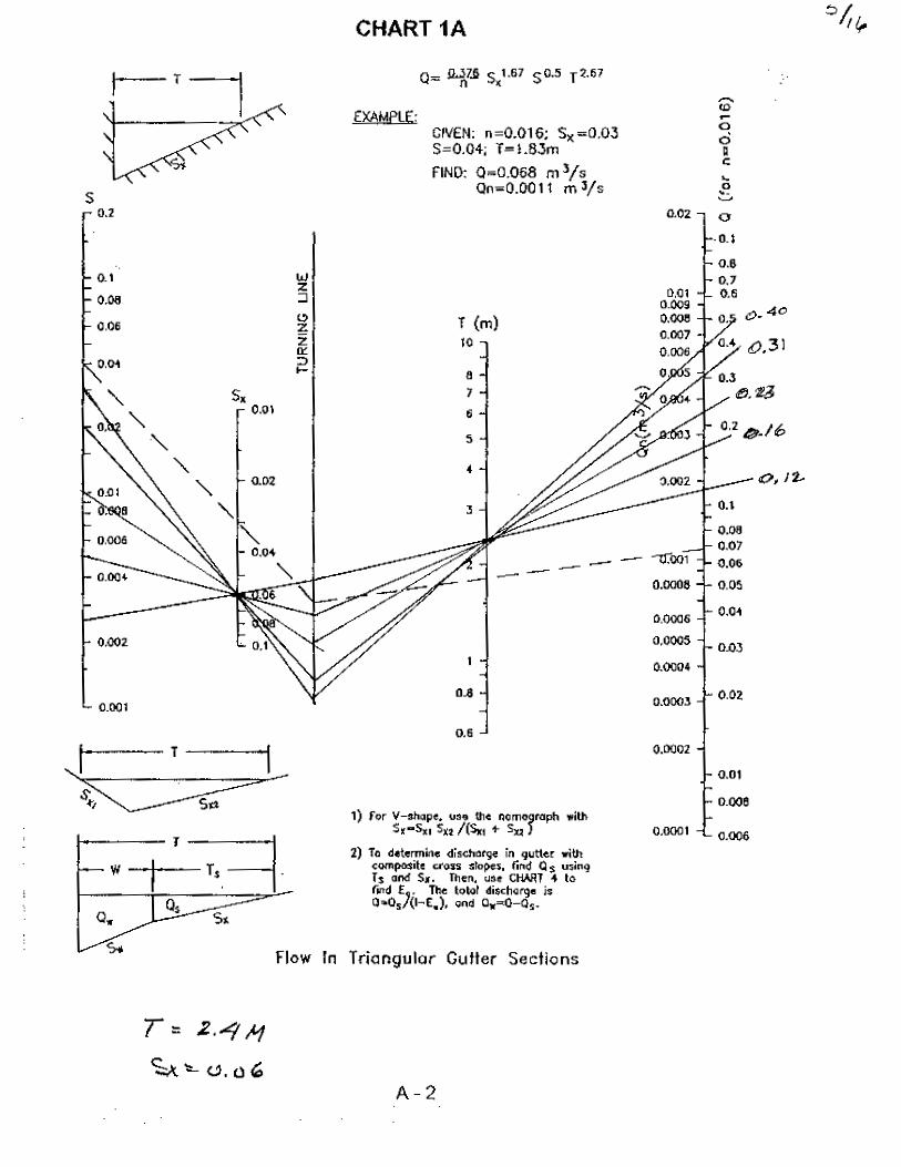
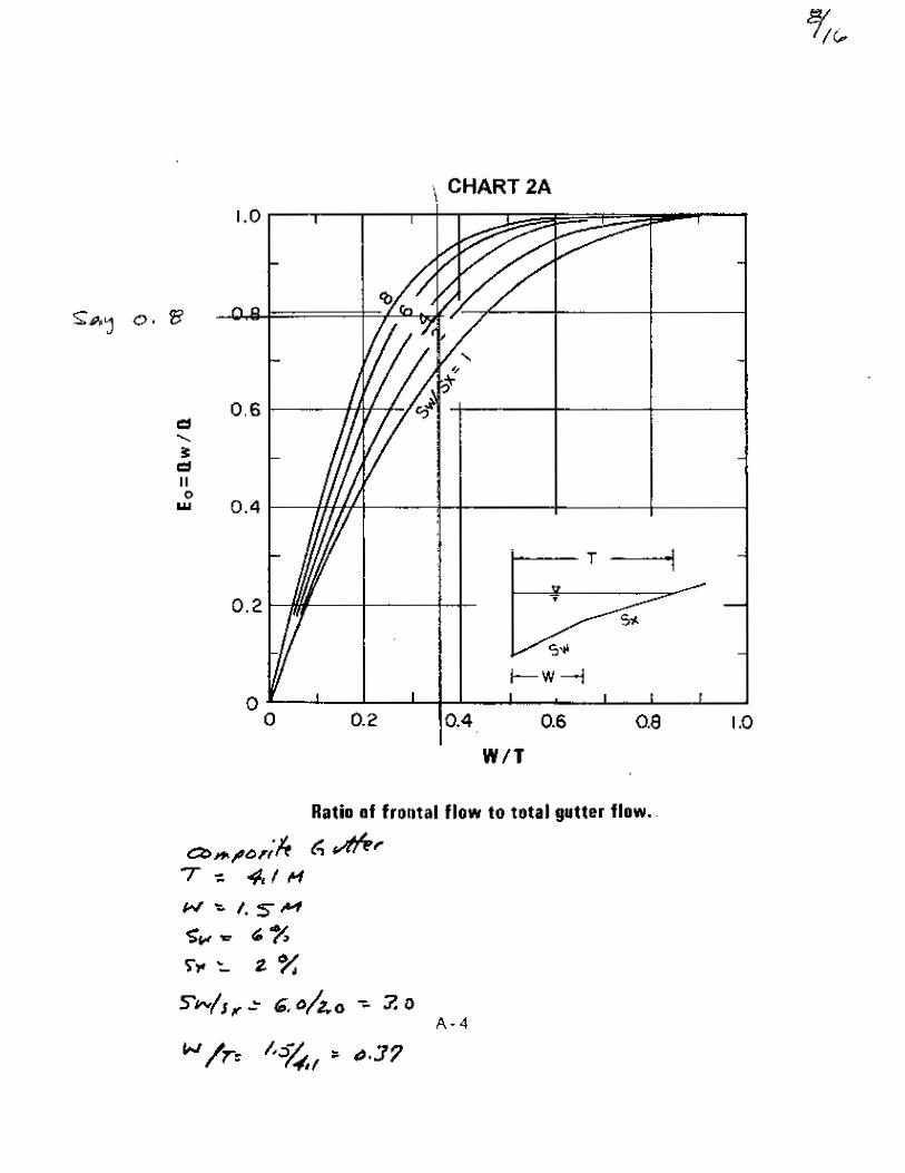
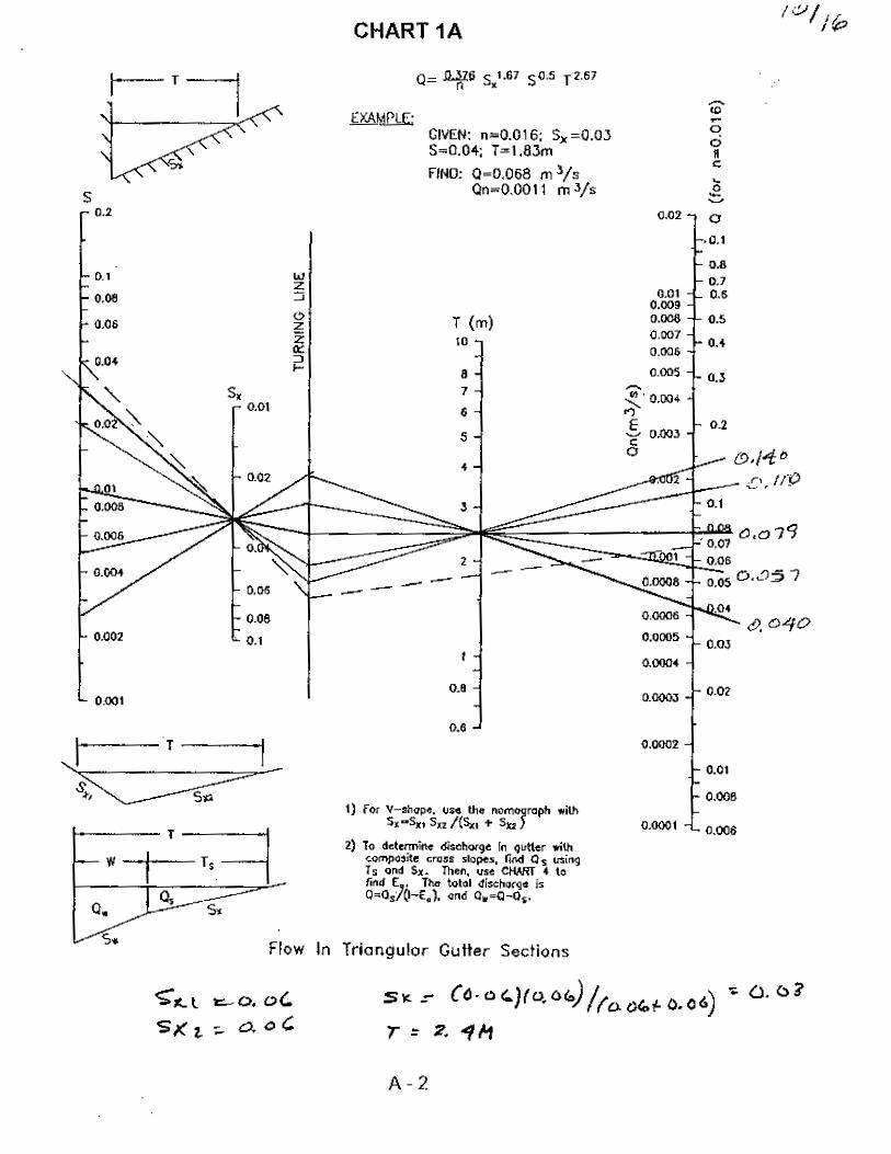
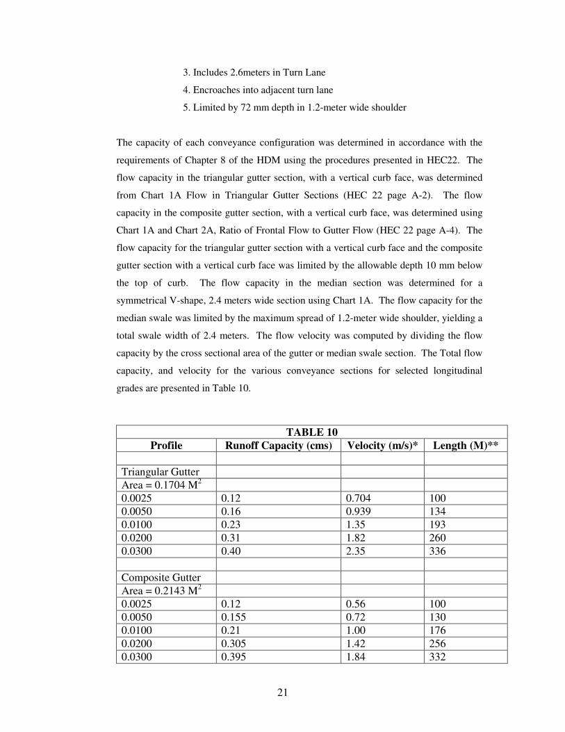
The capacity of each conveyance configuration was determined in accordance with the
requirements of Chapter 8 of the HDM using the procedures presented in HEC22. The
flow capacity in the triangular gutter section, with a vertical curb face, was determined
from Chart 1A Flow in Triangular Gutter Sections (HEC 22 page A-2). The flow
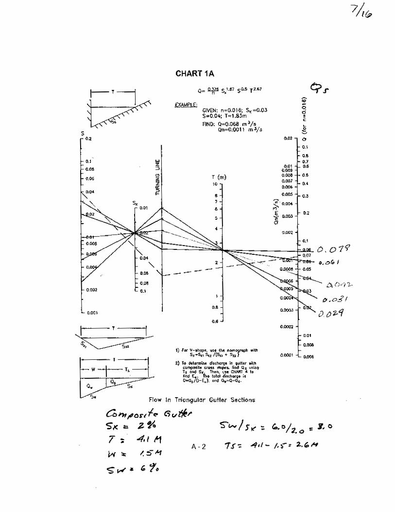
capacity in the composite gutter section, with a vertical curb face, was determined using
Chart 1A and Chart 2A, Ratio of Frontal Flow to Gutter Flow (HEC 22 page A-4). The
flow capacity for the triangular gutter section with a vertical curb face and the composite
gutter section with a vertical curb face was limited by the allowable depth 10 mm below
the top of curb. The flow capacity in the median section was determined for a
symmetrical V-shape, 2.4 meters wide section using Chart 1A. The flow capacity for the
median swale was limited by the maximum spread of 1.2-meter wide shoulder, yielding a
total swale width of 2.4 meters. The flow velocity was computed by dividing the flow
capacity by the cross sectional area of the gutter or median swale section. The Total flow
capacity, and velocity for the various conveyance sections for selected longitudinal
grades are presented in Table 10.
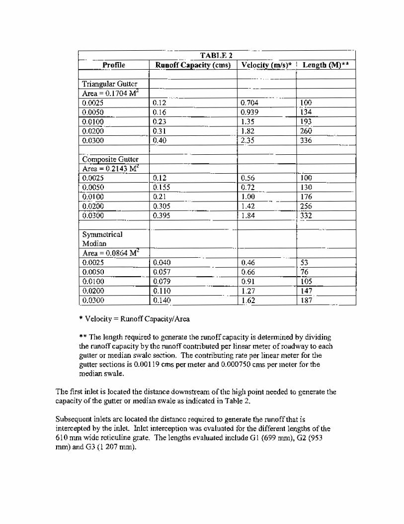
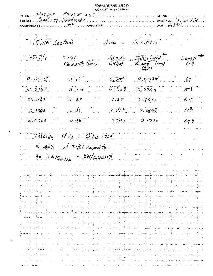
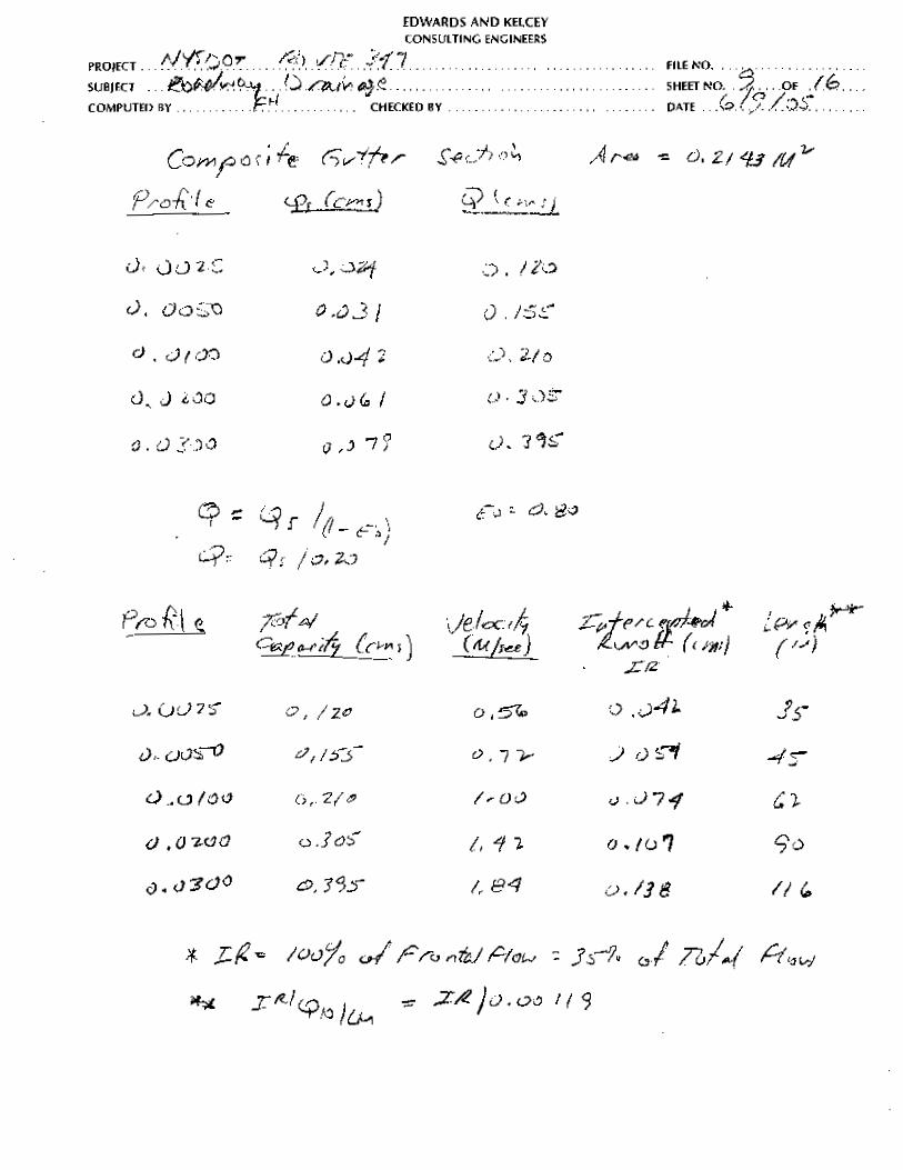
TABLE 10 Profile Runoff Capacity (cms) Velocity (m/s)* Length (M)**
Triangular Gutter Area = 0.1704 M2 0.0025 0.12 0.704 100 0.0050 0.16 0.939 134 0.0100 0.23 1.35 193 0.0200 0.31 1.82 260 0.0300 0.40 2.35 336 Composite Gutter Area = 0.2143 M2 0.0025 0.12 0.56 100 0.0050 0.155 0.72 130 0.0100 0.21 1.00 176 0.0200 0.305 1.42 256 0.0300 0.395 1.84 332
22
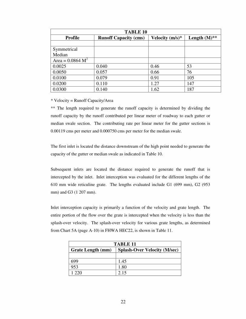
TABLE 10 Profile Runoff Capacity (cms) Velocity (m/s)* Length (M)**
Symmetrical Median
Area = 0.0864 M2 0.0025 0.040 0.46 53 0.0050 0.057 0.66 76 0.0100 0.079 0.91 105 0.0200 0.110 1.27 147 0.0300 0.140 1.62 187
* Velocity = Runoff Capacity/Area
** The length required to generate the runoff capacity is determined by dividing the
runoff capacity by the runoff contributed per linear meter of roadway to each gutter or
median swale section. The contributing rate per linear meter for the gutter sections is
0.00119 cms per meter and 0.000750 cms per meter for the median swale.
The first inlet is located the distance downstream of the high point needed to generate the
capacity of the gutter or median swale as indicated in Table 10.
Subsequent inlets are located the distance required to generate the runoff that is
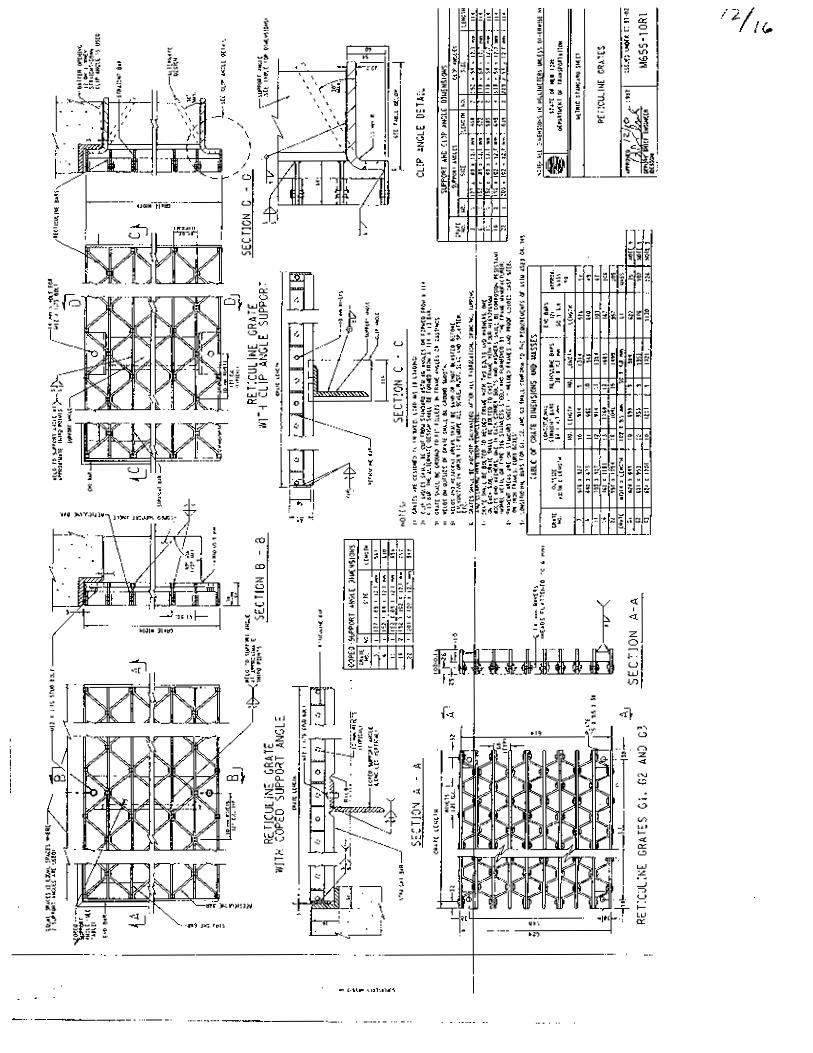
intercepted by the inlet. Inlet interception was evaluated for the different lengths of the
610 mm wide reticuline grate. The lengths evaluated include G1 (699 mm), G2 (953
mm) and G3 (1 207 mm).
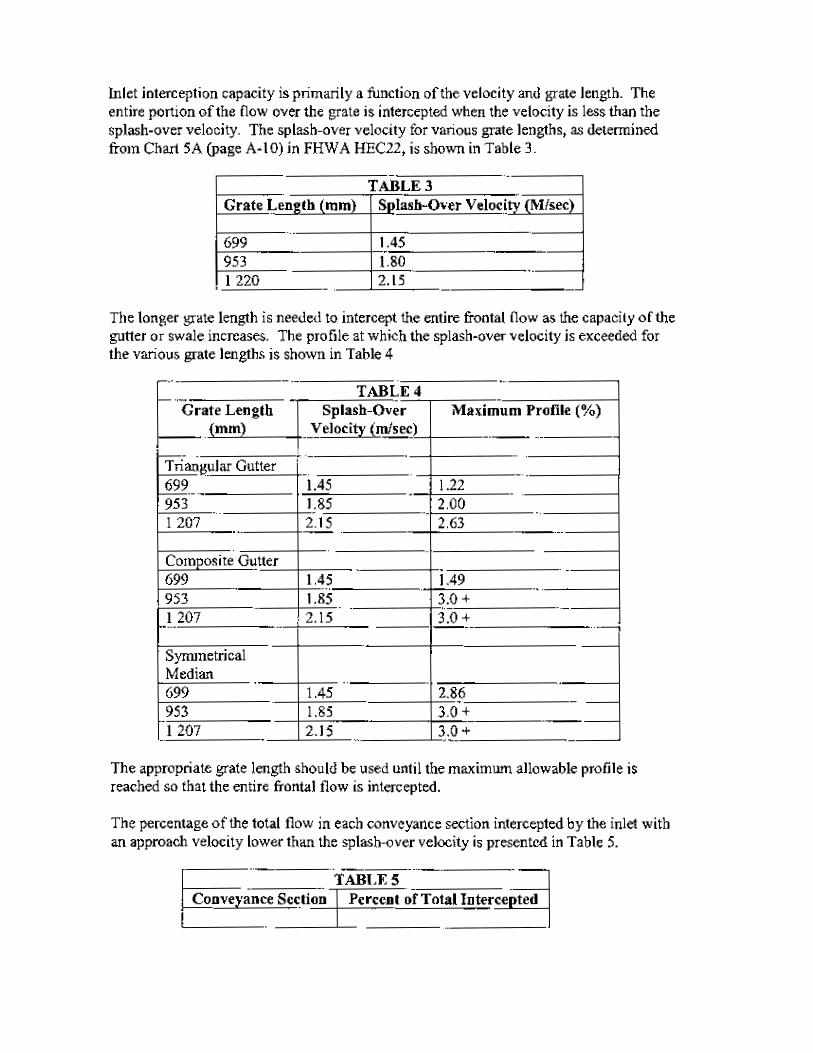
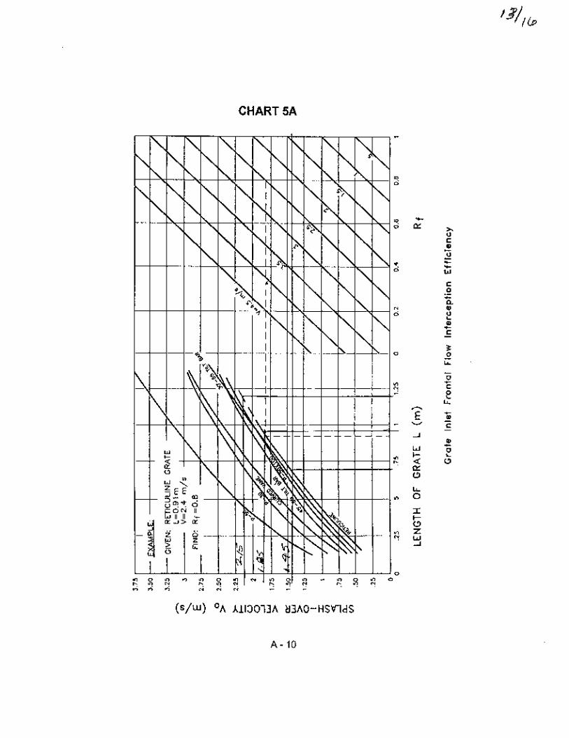
Inlet interception capacity is primarily a function of the velocity and grate length. The
entire portion of the flow over the grate is intercepted when the velocity is less than the
splash-over velocity. The splash-over velocity for various grate lengths, as determined
from Chart 5A (page A-10) in FHWA HEC22, is shown in Table 11.
TABLE 11
Grate Length (mm) Splash-Over Velocity (M/sec) 699 1.45 953 1.80 1 220 2.15
23
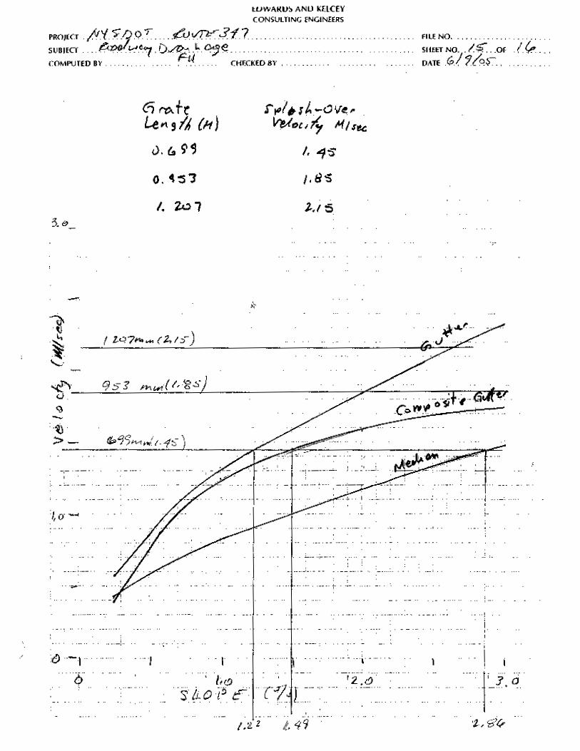
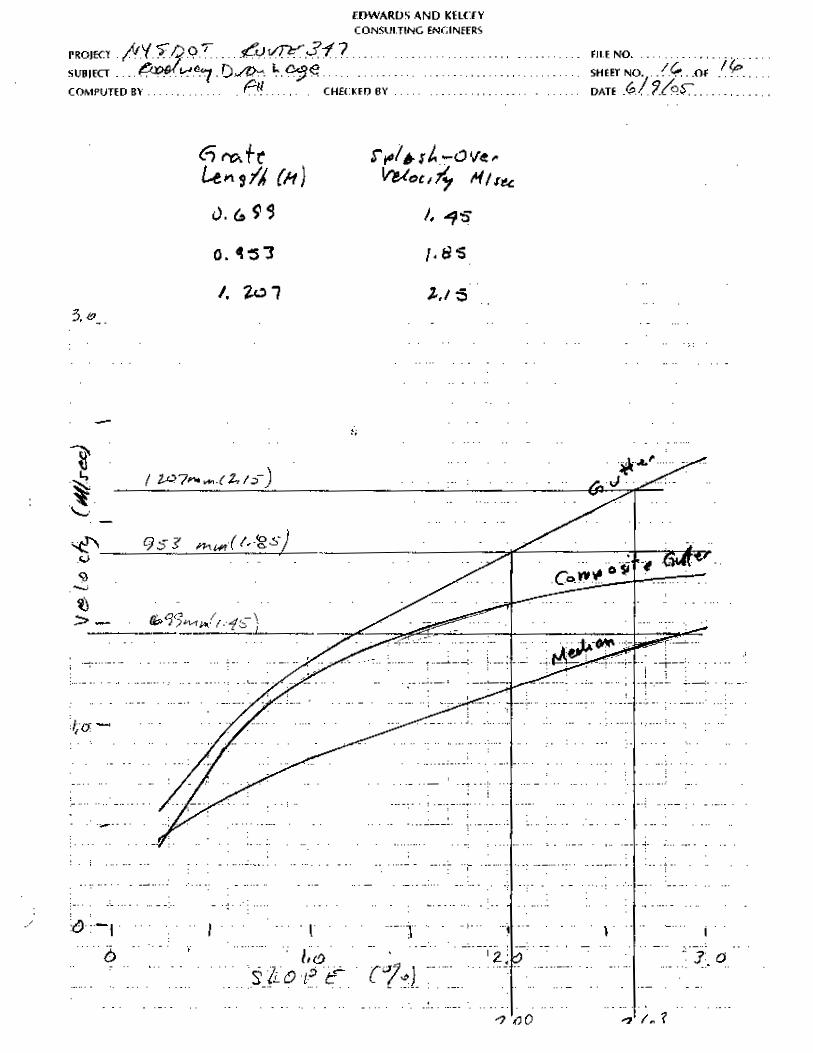
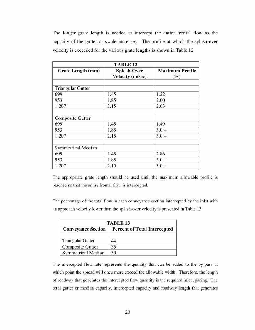
The longer grate length is needed to intercept the entire frontal flow as the
capacity of the gutter or swale increases. The profile at which the splash-over
velocity is exceeded for the various grate lengths is shown in Table 12
TABLE 12
Grate Length (mm) Splash-Over Velocity (m/sec)
Maximum Profile (%)
Triangular Gutter 699 1.45 1.22 953 1.85 2.00 1 207 2.15 2.63 Composite Gutter 699 1.45 1.49 953 1.85 3.0 + 1 207 2.15 3.0 + Symmetrical Median 699 1.45 2.86 953 1.85 3.0 + 1 207 2.15 3.0 +
The appropriate grate length should be used until the maximum allowable profile is
reached so that the entire frontal flow is intercepted.
The percentage of the total flow in each conveyance section intercepted by the inlet with
an approach velocity lower than the splash-over velocity is presented in Table 13.
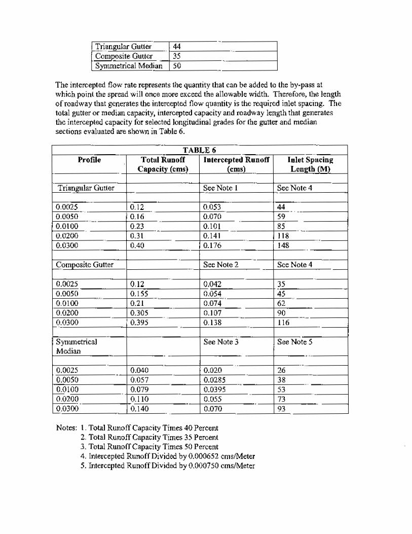
TABLE 13
Conveyance Section Percent of Total Intercepted Triangular Gutter 44 Composite Gutter 35 Symmetrical Median 50
The intercepted flow rate represents the quantity that can be added to the by-pass at
which point the spread will once more exceed the allowable width. Therefore, the length
of roadway that generates the intercepted flow quantity is the required inlet spacing. The
total gutter or median capacity, intercepted capacity and roadway length that generates
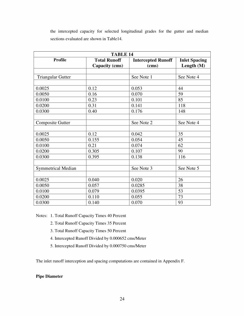
24
the intercepted capacity for selected longitudinal grades for the gutter and median
sections evaluated are shown in Table14.
TABLE 14 Profile Total Runoff
Capacity (cms) Intercepted Runoff
(cms) Inlet Spacing Length (M)
Triangular Gutter See Note 1 See Note 4 0.0025 0.12 0.053 44 0.0050 0.16 0.070 59 0.0100 0.23 0.101 85 0.0200 0.31 0.141 118 0.0300 0.40 0.176 148 Composite Gutter See Note 2 See Note 4 0.0025 0.12 0.042 35 0.0050 0.155 0.054 45 0.0100 0.21 0.074 62 0.0200 0.305 0.107 90 0.0300 0.395 0.138 116 Symmetrical Median See Note 3 See Note 5 0.0025 0.040 0.020 26 0.0050 0.057 0.0285 38 0.0100 0.079 0.0395 53 0.0200 0.110 0.055 73 0.0300 0.140 0.070 93
Notes: 1. Total Runoff Capacity Times 40 Percent
2. Total Runoff Capacity Times 35 Percent
3. Total Runoff Capacity Times 50 Percent
4. Intercepted Runoff Divided by 0.000652 cms/Meter
5. Intercepted Runoff Divided by 0.000750 cms/Meter
The inlet runoff interception and spacing computations are contained in Appendix F.
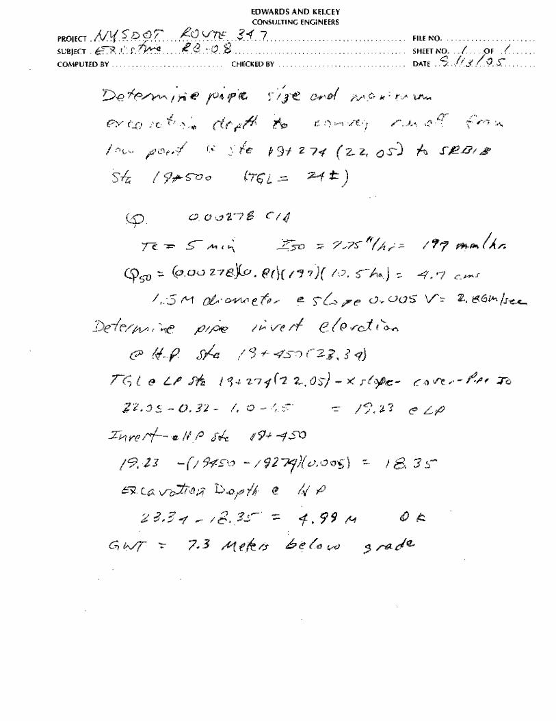
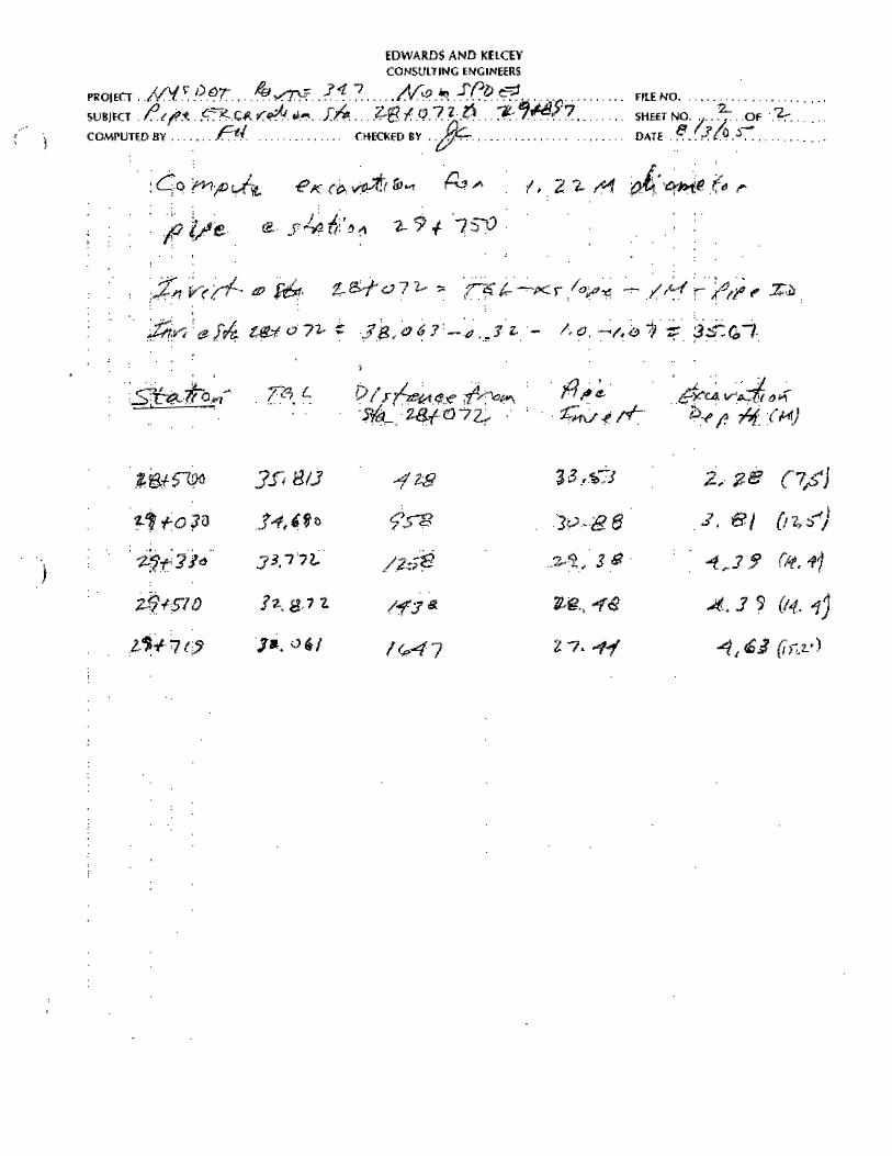
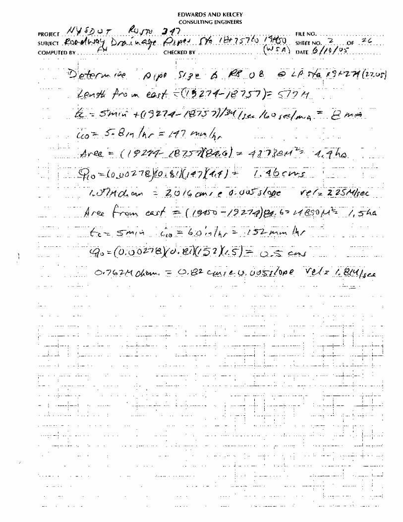
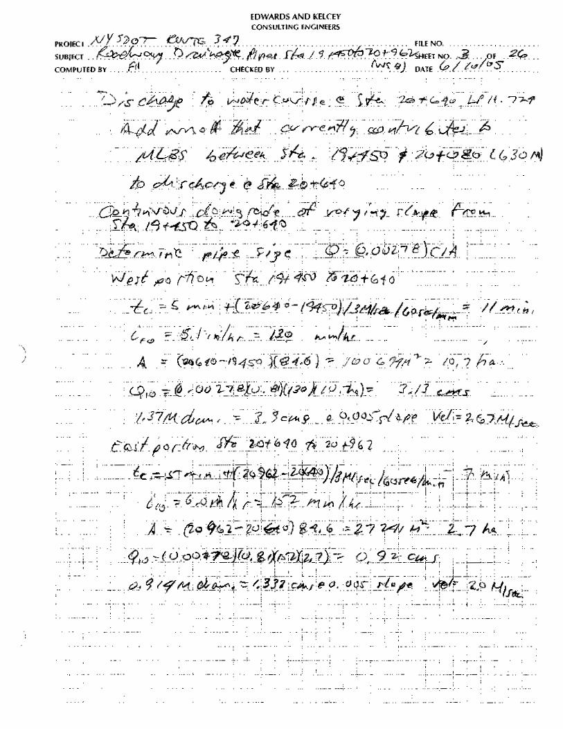
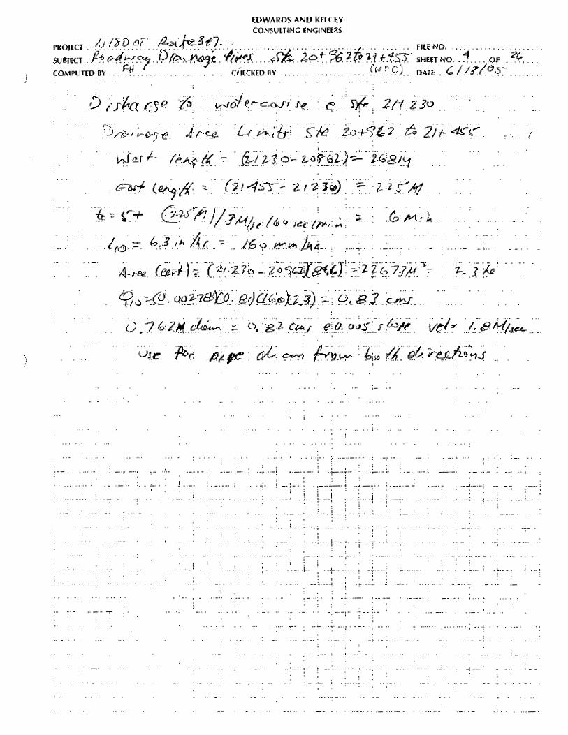
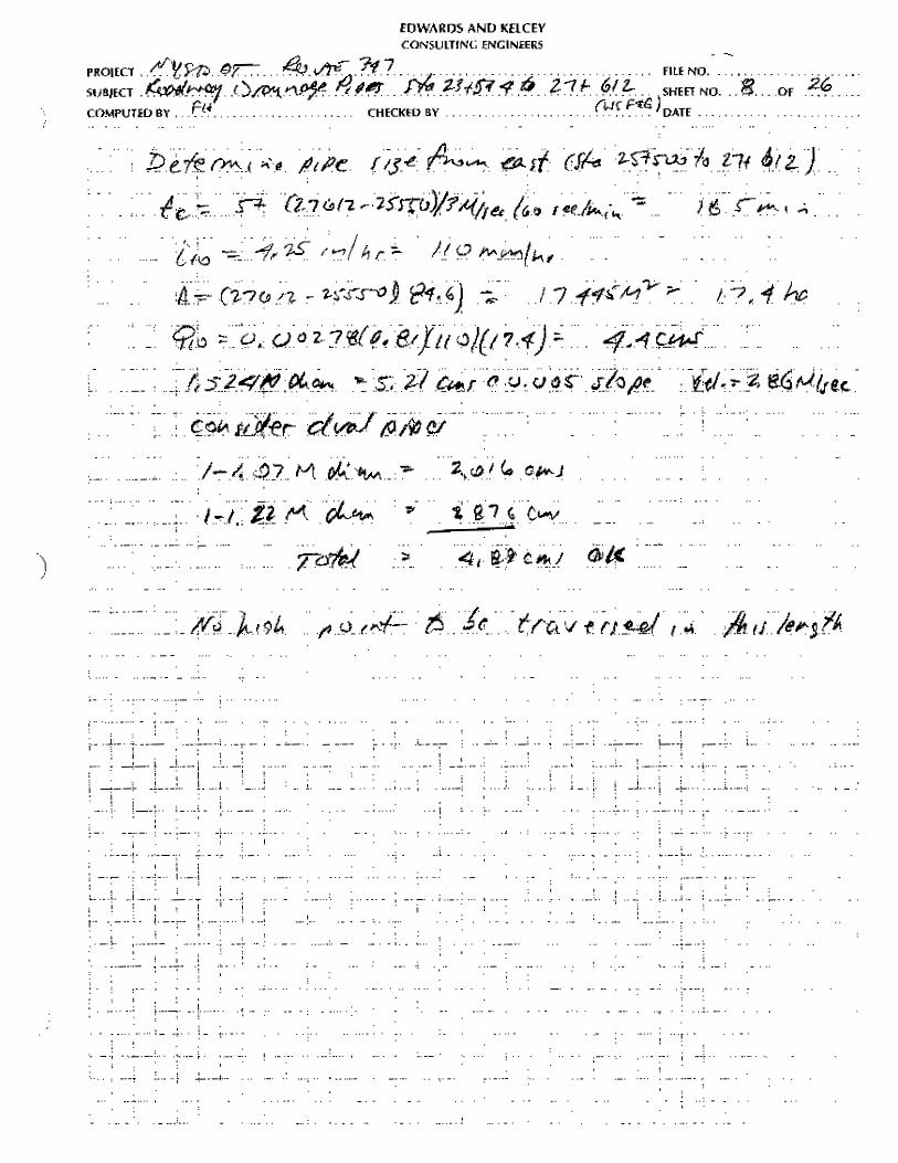
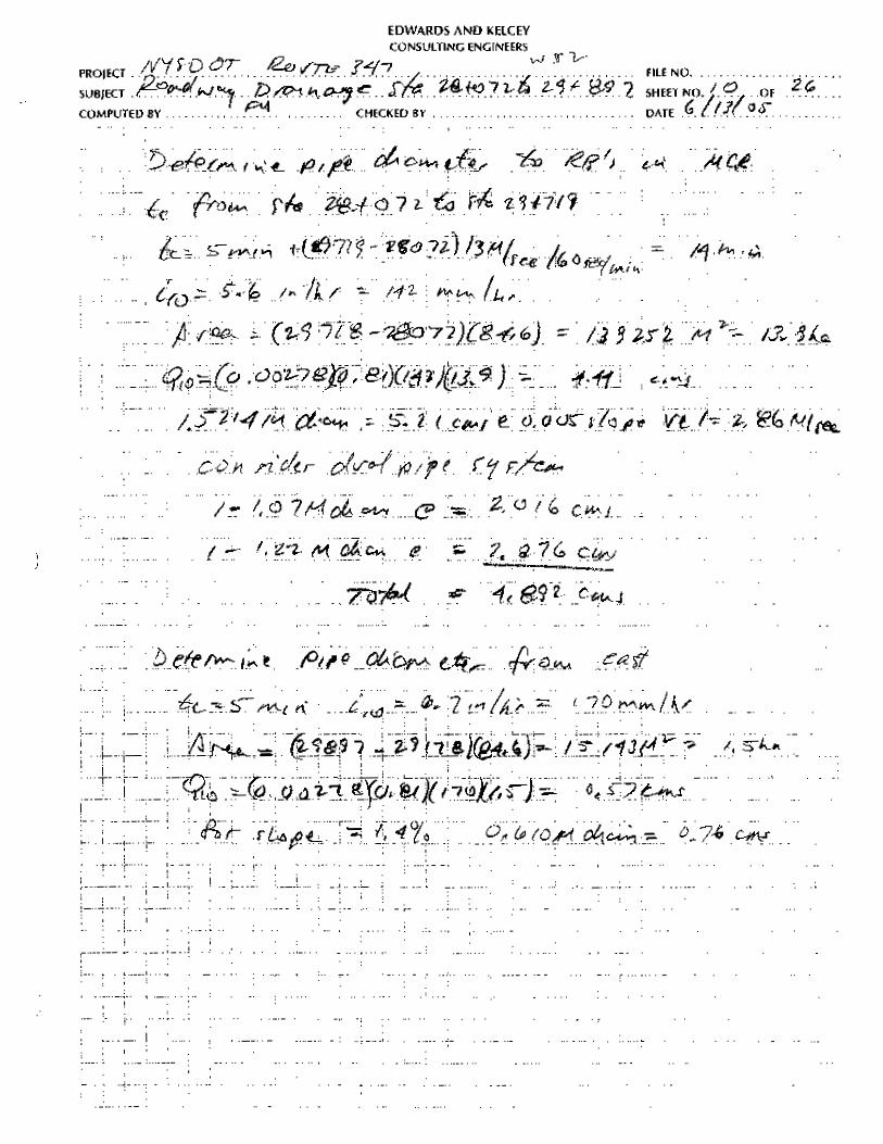
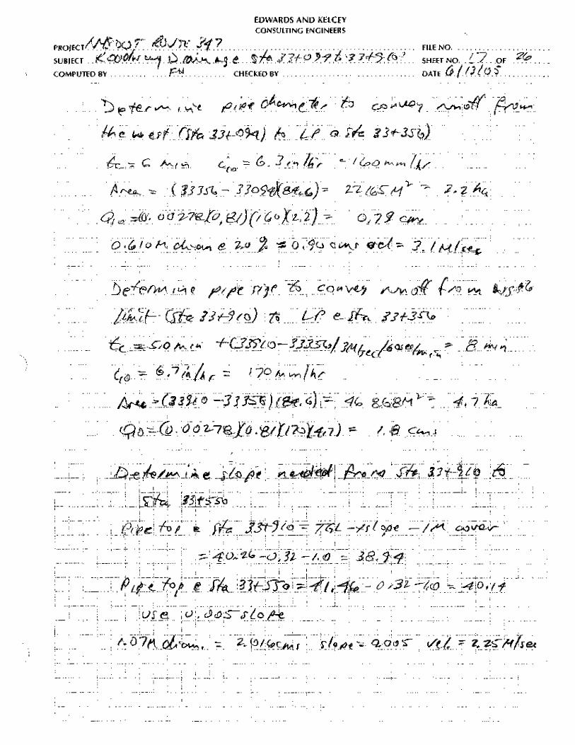
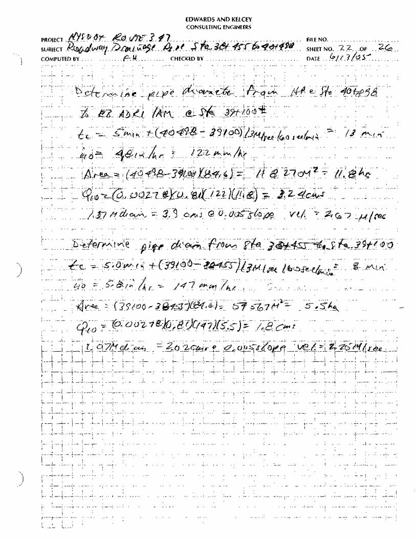
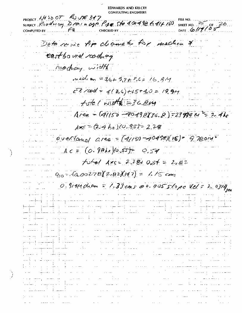
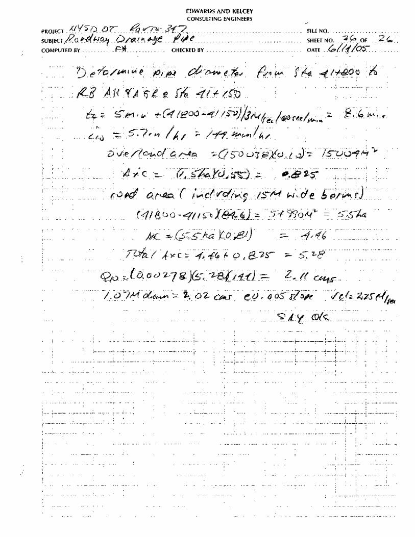
Pipe Diameter
25
Determination of the pipe diameter required to convey the design runoff to the discharge location
includes two components, computation of the design runoff and determination of the resultant
required pipe diameter as explained in the following narrative.
Design Runoff – The design runoff was computed using the rational formula. The calculation
requires determination of the rainfall intensity that is a function of the time of concentration, the
area from which runoff is contributed and the weighted runoff coefficient for the area from which
runoff is contributed. The procedures employed to determine these factors are explained below.
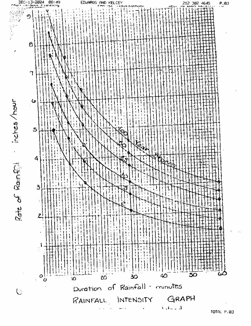
a. Rainfall Intensity – Determined from the charts supplied by Region 10 included in
appendix A. A recurrence interval of once in ten-years was used in compliance with
Table 8-2 in Chapter 8 of the Highway Design Manual.
b. Time of Concentration – computed using a 5 minute minimum plus the run time to
the discharge location using a velocity of three meters per second for the length of the
run to the discharge point.
c. Contributing Area – field observation revealed that, except in isolated locations, the
overland area that contributes runoff to Route 347 is limited to approximately fifteen
meters either side of the edge of the typical section. The Case I typical section was
used in the evaluation because it represents the widest proposed pavement section on
the project. Additional area contributes runoff to westbound Route 347 from
approximately Davis Avenue to Crystal Brook Hollow Road, near the east terminus
of the project.
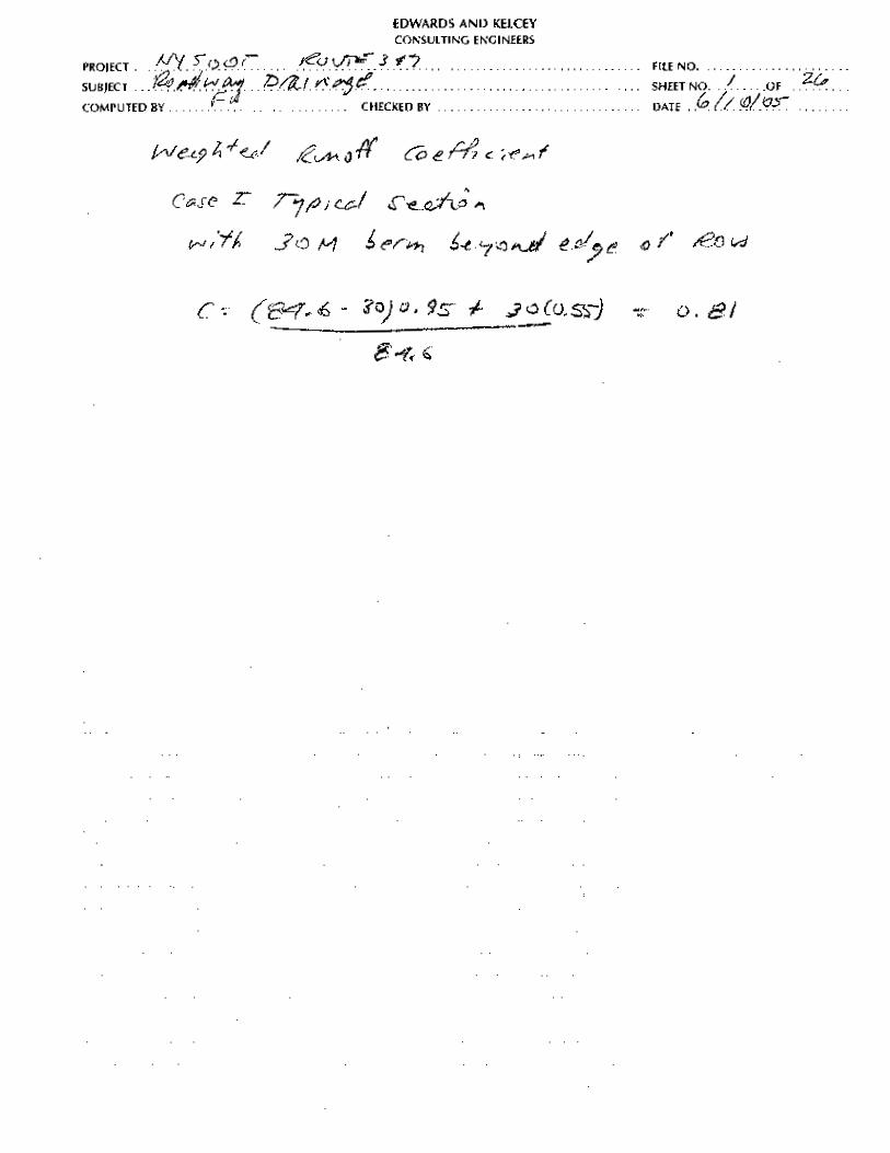
d. Weighted Runoff Coefficient – a runoff coefficient of 0.95 was used for pavement
areas and 0.55 for adjacent unpaved areas to compute the weighted runoff coefficient.
This yielded a weighted runoff coefficient of 0.81.
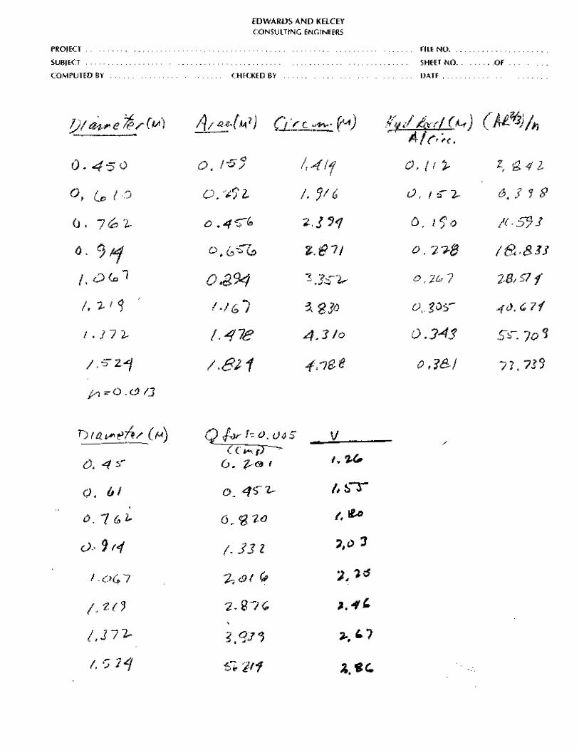
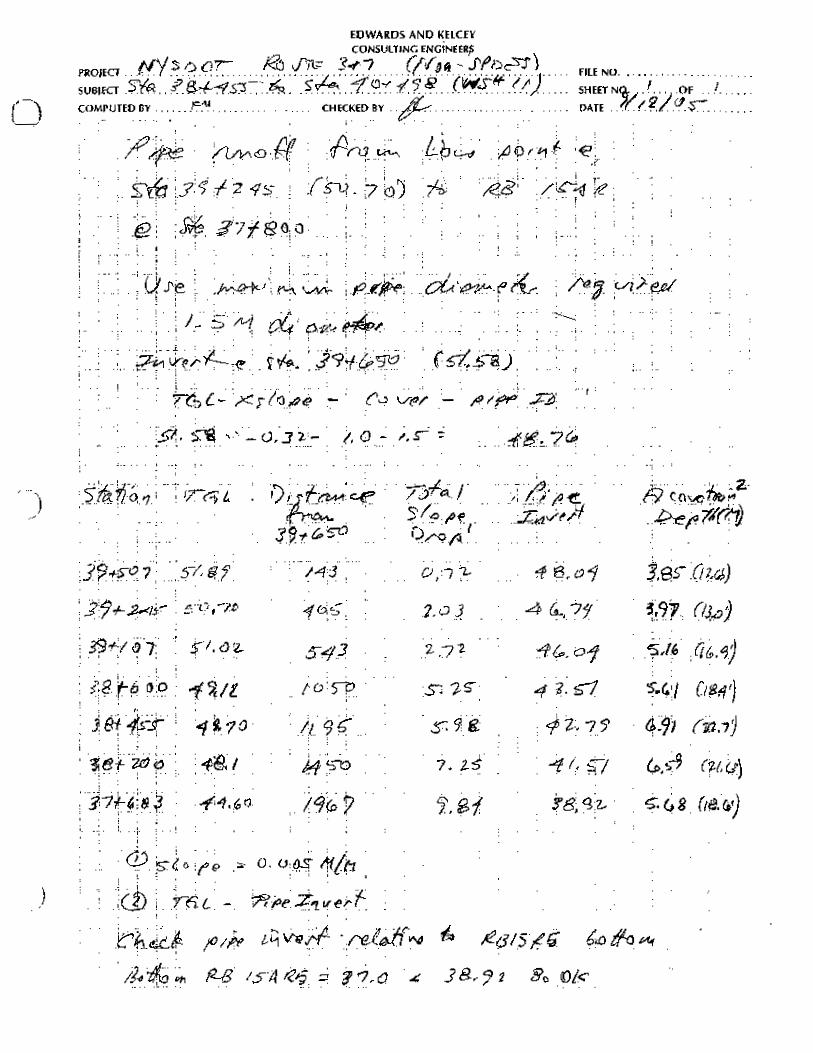
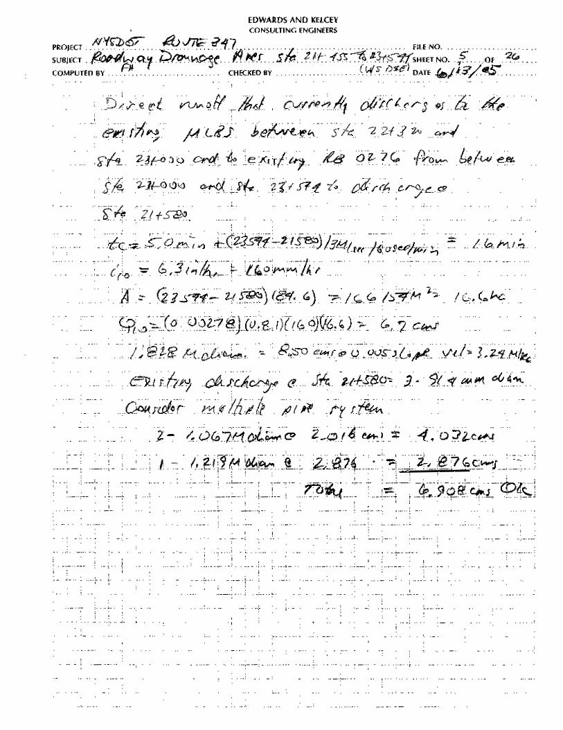
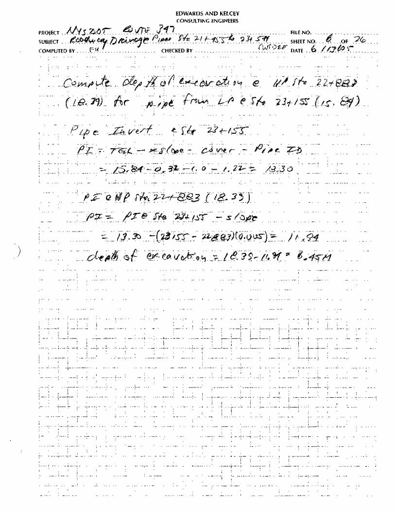
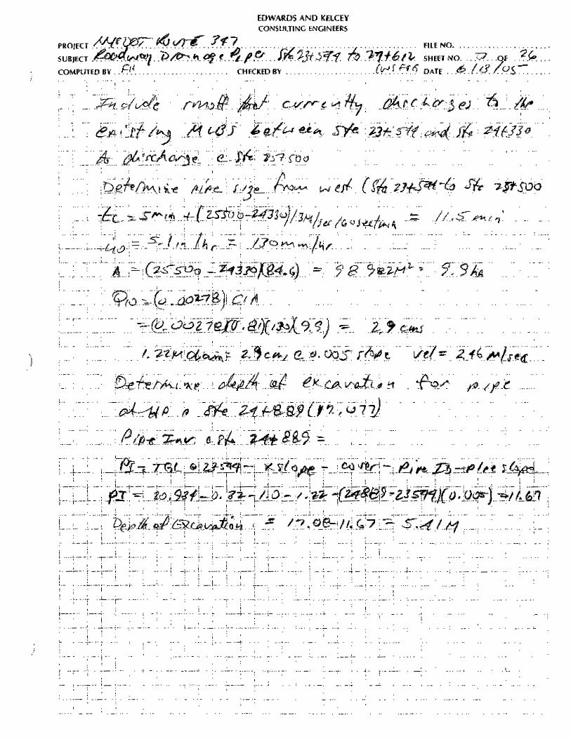
Pipe Diameter - Hydraulic computations were performed using the Manning equation to
determine the diameter of the pipe needed to convey the design runoff to each proposed disposal
location. A friction factor of 0.016 was used. A minimum slope of 0.005 meters per meter was
used, including locations where grades adverse to the roadway vertical geometry were required to
reach the discharge location. The roadway grade was used when it exceeded 0.005 meters per
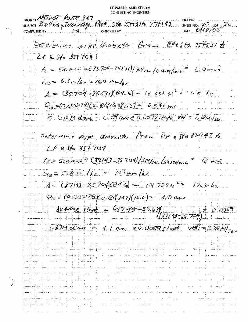
meter. An average slope was computed, using the TGL at the upper and lower ends of the run
divided by the length of the run, when several grades steeper than 0,005 meters per meter were
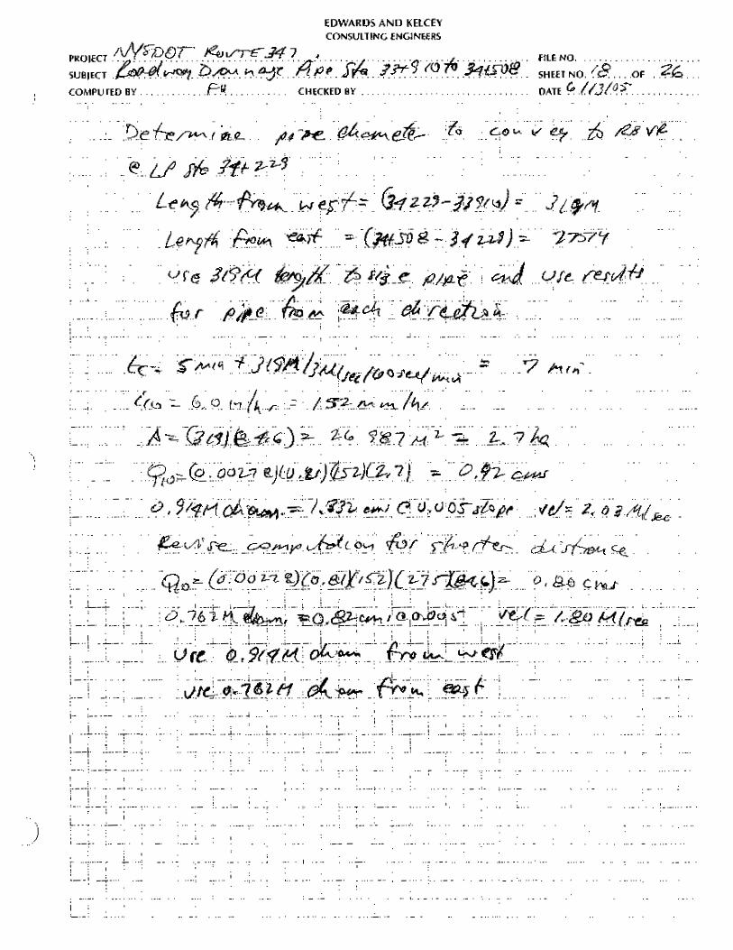
present within the proposed pipe length. The pipe diameter was computed for the runoff at the
26
discharge location for each approach, both from the west and from the east, at each discharge
location.
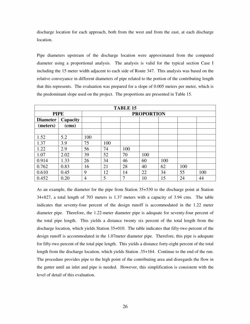
Pipe diameters upstream of the discharge location were approximated from the computed
diameter using a proportional analysis. The analysis is valid for the typical section Case I
including the 15 meter width adjacent to each side of Route 347. This analysis was based on the
relative conveyance in different diameters of pipe related to the portion of the contributing length
that this represents. The evaluation was prepared for a slope of 0.005 meters per meter, which is
the predominant slope used on the project. The proportions are presented in Table 15.
TABLE 15
PIPE PROPORTION Diameter Capacity (meters) (cms)
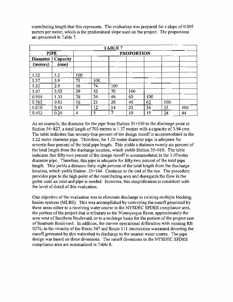
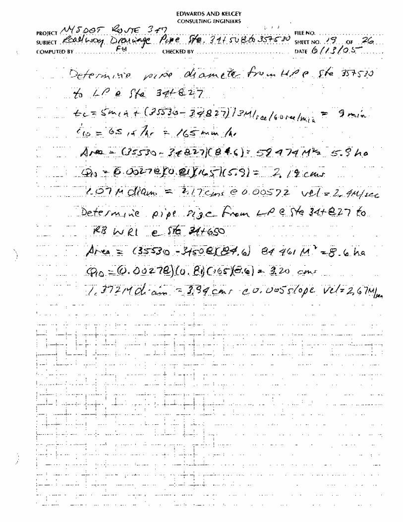
1.52 5.2 100 1.37 3.9 75 100 1.22 2.9 56 74 100 1.07 2.02 39 52 70 100 0.914 1.33 26 34 46 60 100 0.762 0.83 16 21 28 40 62 100 0.610 0.45 9 12 14 22 34 55 100 0.452 0.20 4 5 7 10 15 24 44 As an example, the diameter for the pipe from Station 35+530 to the discharge point at Station
34+827, a total length of 703 meters is 1.37 meters with a capacity of 3.94 cms. The table
indicates that seventy-four percent of the design runoff is accommodated in the 1.22 meter
diameter pipe. Therefore, the 1.22-meter diameter pipe is adequate for seventy-four percent of
the total pipe length. This yields a distance twenty six percent of the total length from the
discharge location, which yields Station 35+010. The table indicates that fifty-two percent of the
design runoff is accommodated in the 1.07meter diameter pipe. Therefore, this pipe is adequate
for fifty-two percent of the total pipe length. This yields a distance forty-eight percent of the total
length from the discharge location, which yields Station .35+164. Continue to the end of the run.
The procedure provides pipe to the high point of the contributing area and disregards the flow in
the gutter until an inlet and pipe is needed. However, this simplification is consistent with the
level of detail of this evaluation.
27
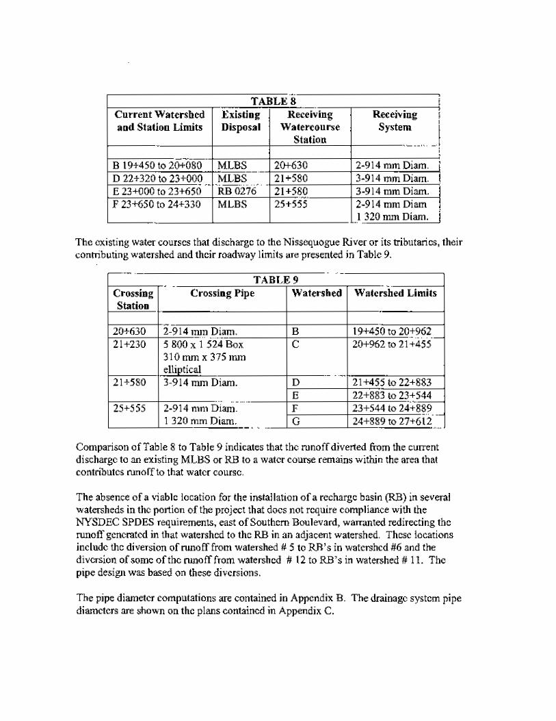
The absence of a viable location for the installation of a recharge basin (RB) in several
watersheds in the portion of the project that does not require compliance with the NYSDEC
SPDES requirements, east of Southern Boulevard, warranted redirecting the runoff generated in
that watershed to the RB in an adjacent watershed. These locations include the diversion of
runoff from watershed # 5 to RB’s in watershed #6 and the diversion of some of the runoff from
watershed # 12 to RB’s in watershed # 11. The pipe design was based on these diversions.
The pipe diameter computations are contained in Appendix F.