Embed Size (px)
Citation preview
Final Proposal: Lunar Exploration Transportation System
(LETS)
Spring 2008 Integrated Product Team (IPT)
Submitted By:
Team Eclipse
April 22, 2008
Submitted To:Dr. Michael P.J. Benfield and Dr. Matthew W. Turner
Associate ProfessorDepartment of Mechanical and Aerospace Engineering
University of Alabama in HuntsvilleHuntsville, AL 35899
[email protected]@uah.edu

Contributors
Project Office Eddie KiesslingSystems Engineering Jay Gala
Guidance Navigation & Control Brandon York / Joseph SandlinPower Chris Goes
Thermal Kathryn KirshOperations/Communications Brett Guin
Payload Brent NewsonStructures Nathan Coffee
Technical Editor Michael Bryan
Sample Return Vehicle Julien Gobeaut Sample Return Vehicle Ghislan Pelieu
Mobility Miles TorrengoMobility Torey CrosbyMobility Juan Loretto
Executive Summary
English
The following report provides detailed information about the design and development of the Lander on Wheels by Team Eclipse. The report identifies the process and technical aspects of the Lander on Wheels, the need for the product, manufacturing considerations, and development issues. The first section of the report deals with the need for the Lander on Wheels system and the requirements given by the customer. The main purpose of the system is to explore the surface of the moon and hopefully return valuable samples to Earth. The technical aspects of the design are discussed in this report. This section includes information on the guidance, navigation, control, power, structures, thermal, and operations systems of Team Eclipse’s design. The main points of each of these systems and how they interact are given, but more specific information can be found in the appendices of the report. The final section of the report addresses manufacturing processes, a summary of the technical information, and lays out Team Eclipse’s recommendations and plans for future development of the LOW system.
French
Le rapport suivant fournit des informations détaillées au sujet de la conception et du développement du Lander sur des roues par Team Eclipse. Le rapport identifie les aspects de processus et techniques du Lander sur des roues, le besoin de produit, des considérations de fabrication, et des questions de développement. La première section du rapport traite le besoin de Lander sur le système de roues et les conditions données par le client. Le but principal du système est d'explorer la surface de la lune et si tout va bien des échantillons valables de retour à la terre. Les aspects techniques de la conception sont discutés dans ce rapport. Cette section inclut l'information sur les conseils, la navigation, la commande, la puissance, les structures, le courant ascendant, et les systèmes d'opérations de la conception de l'éclipse d'équipe. Les points principaux de chacun de ces systèmes et comment ils agissent l'un sur l'autre sont indiqués, mais l'information plus spécifique peuvent être trouvés dans les annexes du rapport. La section finale du rapport adresse les processus de fabrication, un résumé d'information technique, et présente les recommandations et les plans de l'éclipse d'équipe pour le futur développement du BAS système
iii

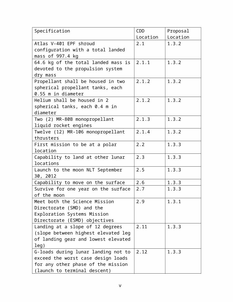
LOW Compliance Matrix
Specification CDD Location
Proposal Location
Atlas V-401 EPF shroud configuration with a total landed mass of 997.4 kg
2.1 1.3.2
64.6 kg of the total landed mass is devoted to the propulsion system dry mass
2.1.1 1.3.2
Propellant shall be housed in two spherical propellant tanks, each 0.55 m in diameter
2.1.2 1.3.2
Helium shall be housed in 2 spherical tanks, each 0.4 m in diameter
2.1.2 1.3.2
Two (2) MR-80B monopropellant liquid rocket engines
2.1.3 1.3.2
Twelve (12) MR-106 monopropellant thrusters 2.1.4 1.3.2First mission to be at a polar location 2.2 1.3.3Capability to land at other lunar locations 2.3 1.3.3Launch to the moon NLT September 30, 2012 2.5 1.3.3Capability to move on the surface 2.6 1.3.3Survive for one year on the surface of the moon 2.7 1.3.3Meet both the Science Mission Directorate (SMD) and the Exploration Systems Mission Directorate (ESMD) objectives
2.9 1.3.1
Landing at a slope of 12 degrees (slope between highest elevated leg of landing gear and lowest elevated leg)
2.11 1.3.3
G-loads during lunar landing not to exceed the worst case design loads for any other phase of the mission (launch to terminal descent)
2.12 1.3.3
iv
Table of Contents
List of Figures..................................................................................................................vii
List of Tables...................................................................................................................viii
Common Terms and Acronyms......................................................................................iii
IPT 02: Final Report Feasibility of Lunar Exploration Transportation System........1
1.0 Final Report: Lander on Wheels Concept.................................................................1
1.1 Overview...................................................................................................................1
1.2 The Need...................................................................................................................1
1.3 The Requirements....................................................................................................2
1.4 The Solution..............................................................................................................31.4.1 Concept Overview..............................................................................................31.4.2 Dimensional Properties.......................................................................................41.4.3 Operations Scenario............................................................................................4
1.5 The Performance......................................................................................................51.5.1 LETS Figures of Merit........................................................................................51.5.2 Surface Objectives..............................................................................................51.5.3 Percentage of Payload Mass...............................................................................51.5.4 Ratio of SMD to ESMD Validation....................................................................51.5.5 Data Efficiency...................................................................................................61.5.6 Percentage of Power System...............................................................................61.5.7 Ratio of off the shelf technology to new technology..........................................61.5.8 LOW Attributes..................................................................................................6
1.6 The Implementation................................................................................................61.6.1 Design and Research Phase................................................................................61.6.2 Testing Phase......................................................................................................7
v
1.6.3 Implementation...................................................................................................7
2.0 Technical Description of Methods Used....................................................................8
2.1 Overview...................................................................................................................8
2.2 Project Office............................................................................................................8
2.3 Systems Engineering................................................................................................9
2.4 Power.......................................................................................................................112.4.1 Power Subsystem Summary.............................................................................112.4.2 Power Equipment..............................................................................................122.4.3 Power Controller and Phase Missions..............................................................13
2.5 Guidance, Navigation, and Control......................................................................142.5.1: System Overview.............................................................................................142.5.2: Terminal Descent Phase...................................................................................142.5.3: Excursion Phase...............................................................................................162.5.5 Redundancy.......................................................................................................19
2.6 Thermal...................................................................................................................19
2.7 Structures...............................................................................................................25
2.8 Payload....................................................................................................................28
2.9 Communication......................................................................................................33
2.10 Concept of Operations.........................................................................................34
2.11 Systems Interactions............................................................................................37
3.0 Implementation Issues...............................................................................................39
3.1 Schedule..................................................................................................................39
3.2 Hardware Development........................................................................................40
4.0 Team Capabilities......................................................................................................41
4.1 Team Overview......................................................................................................41
4.2 Personnel Description............................................................................................41
5.0 Summary and Conclusions.......................................................................................44
5.1 Summary of Design Process..................................................................................44
5.2 Conclusions on Functionality and Science Capability........................................44
6.0 Recommendations......................................................................................................45
Appendices......................................................................................................................1
Appendix A - Concept Description Document............................................................1
Appendix B – Power......................................................................................................5
Appendix C - Guidance, Navigation, and Control......................................................7
Appendix D – Thermal..................................................................................................9
vi
Appendix F - Payload..................................................................................................14
Appendix G – SRV.......................................................................................................19
Appendix H- Communications...................................................................................28
Appendix I - Concept of Operations..........................................................................29
Appendix J - Level II Requirements..........................................................................36
References.........................................................................................................................49
List of Figures
Figure 1: Concept Drawing for LOW..................................................................................4Figure 2: Radiator Temperature as a function of Emissivity.............................................22Figure 3: Radiator Temperature as a function of its Area.................................................22Figure 4: Temperature of the Rover as a function of Emissivity (Cold Case)..................23Figure 5: Temperature of the Rover as a function of Emissivity (Hot Case)....................23Figure 6: Schematic of heat pipe.......................................................................................24Figure 7: FEA Analysis on Leg Joiner..............................................................................25Figure 8: FEA Analysis of Main Member.........................................................................26Figure 9: FEA Analysis of Top of Lander Leg..................................................................27Figure 10: SRV View 1.....................................................................................................30Figure 11: SRV View 2.....................................................................................................30Figure 12: Top View of Payload without Cover...............................................................31Figure 13: Bottom View of Payload without Cover..........................................................32Figure 14: Completed CAD Modeling of LOW................................................................33Figure 15: Lunar South Pole Region with Lander on Wheels Mission Course.................36Figure 16: Systems Interacting with Other Systems..........................................................37
vii
List of TablesTable 1: Customer Requirements........................................................................................2Table 2: Figures of Merit.....................................................................................................5Table 3: List of Low Parameters.......................................................................................10Table 4: Phase Mission Power Budget..............................................................................11Table 5: Maximum Peek Load for subsystems..................................................................12Table 6: Temperature Ranges for Selected Equipment.....................................................20Table 7: Development Schedule........................................................................................39Table 8: List of Hardware on LOW...................................................................................40
viii
ix
Common Terms and AcronymsWord or symbol Comments
AP Alpha ParticleBPM Bytes per Minute
BellyCam Belly CameraCAD Computer Aided DraftingCDD Concept Description Document
C&DH Command and Data Handlingcm³ Cubic CentimetersºC Degrees Celsius
DSMAC Digital Scene Matching Area CorrelatorEOM End of Mission
ESTACA Ecole Supérieure des Techniques Aéronautiques et de Construction Automobile
GCMS Gas Chromatograph Mass SpectrometerFEA Finite Element AnalysisFOM Figures of Merit
Hazcam Hazardous CameraH Hours
IMU Inertial Measurement UnitIPT Integrated Product Team KelvinKg Kilogram
LETS Lunar Exploration Transportation SystemLEP Lunar Excursion Phase
LiDAR Light Detection & RangingLi-ION Lithium IonLOW Lander on Wheels LPRP Lunar Precursor Robotic ProgramLRO Lunar Reconnaissance Orbitermin MinutesMSL Mars Science Laboratory
MTBF Mean Time Between FailureNASA National Aeronautics & Space Administration
Navcam Navigation CameraPancam Panoramic Camera
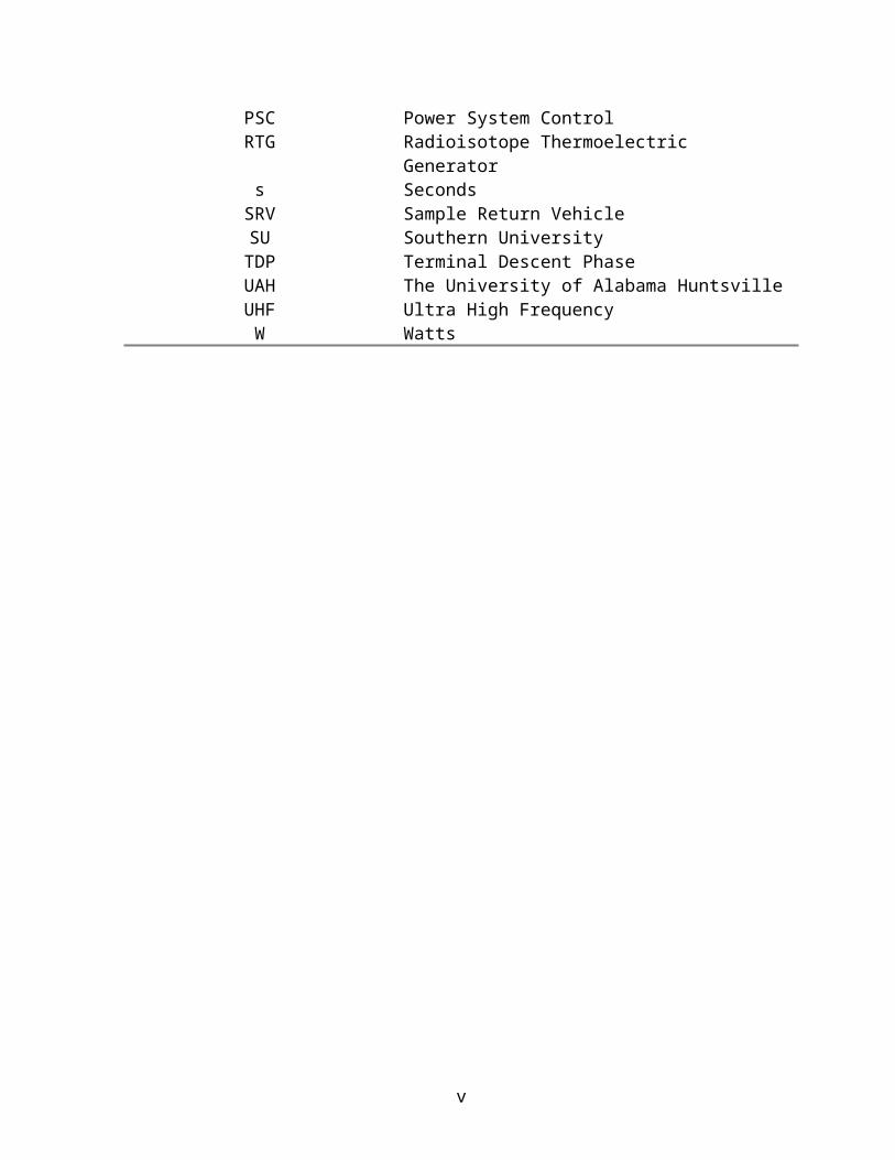
PSC Power System ControlRTG Radioisotope Thermoelectric Generator
s SecondsSRV Sample Return VehicleSU Southern University
TDP Terminal Descent PhaseUAH The University of Alabama HuntsvilleUHF Ultra High Frequency
W Watts
iii
IPT 02: Final Report Feasibility of Lunar Exploration Transportation System
1
1.0 Final Report: Lander on Wheels Concept
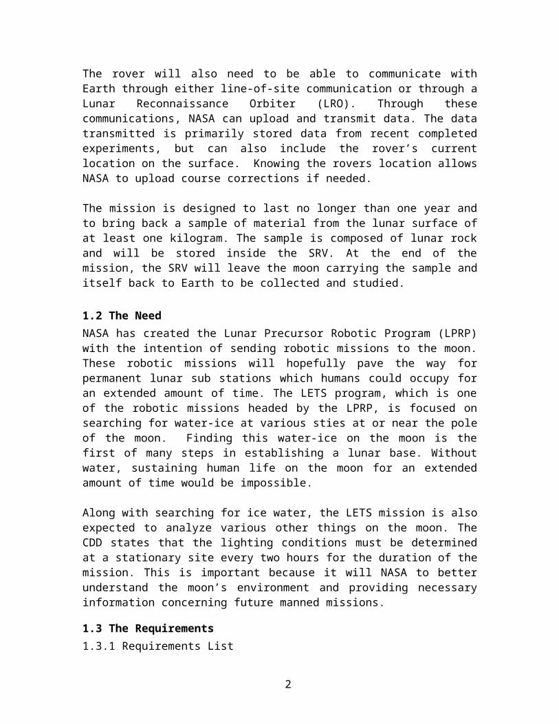
1.1 OverviewThis document outlines the specifications for the Lunar Exploration Transportation System (LETS). The purpose of the LETS project is to develop a lunar lander for NASA that provides the flexibility to conduct different scientific investigations and technology validation tasks at different areas on the moon’s surface. Only one lander is desired for the mission. The mobility of the lander system is subject to trade. For the purposes of this project, the mission will begin with terminal descent and end when the Sample Return Vehicle (SRV) leaves the lunar surface. The goal of the project is to design the transportation vehicle which could perform and accomplish scientific experiments and technology objectives.
The purpose of the lander is to land at a polar location, then travel to various locations to conduct experiments. Each experiment is desired to take place 500 meters away from any other site. The experiments are conducted in 20 predetermined locations. Fifteen of these locations are located on the far side of the moon, while the remaining five locations are located on the near side. The number of locations and the distance between them allows for an accurate sampling over a wide area.
While traveling to each site the rover will need to traverse terrain and navigate through and around unknown regions. Since line-of-site communication will be difficult for most of the mission, the rover will need to be self automated.
The rover will also need to be able to communicate with Earth through either line-of-site communication or through a Lunar Reconnaissance Orbiter (LRO). Through these communications, NASA can upload and transmit data. The data transmitted is primarily stored data from recent completed experiments, but can also include the rover’s current location on the surface. Knowing the rovers location allows NASA to upload course corrections if needed.
The mission is designed to last no longer than one year and to bring back a sample of material from the lunar surface of at least one kilogram. The sample is composed of lunar rock and will be stored inside the SRV. At the end of the mission, the SRV will leave the moon carrying the sample and itself back to Earth to be collected and studied.
1.2 The NeedNASA has created the Lunar Precursor Robotic Program (LPRP) with the intention of sending robotic missions to the moon. These robotic missions will hopefully pave the way for permanent lunar sub stations which humans could occupy for an extended amount of time. The LETS program, which is one of the robotic missions headed by the LPRP, is focused on searching for water-ice at various sties at or near the pole of the moon. Finding this water-ice on the moon is the first of many steps in establishing a lunar base. Without water, sustaining human life on the moon for an extended amount of time would be impossible.
2

Along with searching for ice water, the LETS mission is also expected to analyze various other things on the moon. The CDD states that the lighting conditions must be determined at a stationary site every two hours for the duration of the mission. This is important because it will NASA to better understand the moon’s environment and providing necessary information concerning future manned missions.
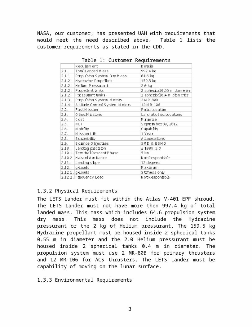
1.3 The Requirements1.3.1 Requirements ListNASA, our customer, has presented UAH with requirements that would meet the need described above. Table 1 lists the customer requirements as stated in the CDD.
Table 1: Customer Requirements
1.3.2 Physical RequirementsThe LETS Lander must fit within the Atlas V-401 EPF shroud. The LETS Lander must not have more then 997.4 kg of total landed mass. This mass which includes 64.6 propulsion system dry mass. This mass does not include the Hydrazine pressurant or the 2 kg of Helium pressurant. The 159.5 kg Hydrazine propellant must be housed inside 2 spherical tanks 0.55 m in diameter and the 2.0 Helium pressurant must be housed inside 2 spherical tanks 0.4 m in diameter. The propulsion system must use 2 MR-80B for primary thrusters and 12 MR-106 for ACS thrusters. The LETS Lander must be capability of moving on the lunar surface.
1.3.3 Environmental Requirements
3

The LETS Lander must land first at a polar location with a ± 100m 3 σ precision with the capability of landing at other lunar locations. The descent starts at 5 km to the lunar surface. The Lander must survive maximum g loads and only account for stiffness and not responsible for frequency loads. The LETS Lander must survive the lunar environment which includes 400 K at equator for maximum temperature and 50 K at perpetual dark for minimum temperature.
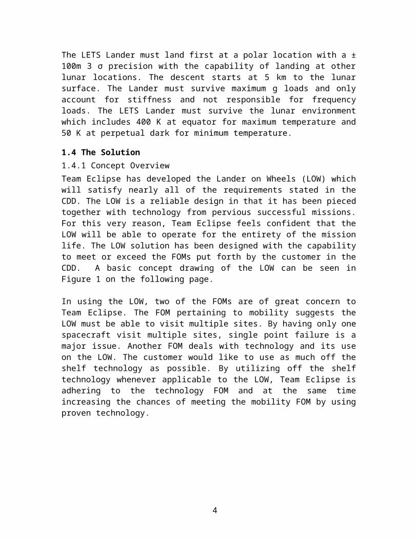
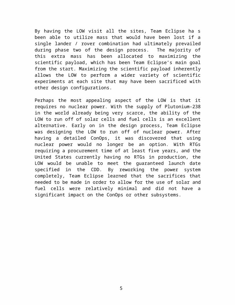
1.4 The Solution1.4.1 Concept OverviewTeam Eclipse has developed the Lander on Wheels (LOW) which will satisfy nearly all of the requirements stated in the CDD. The LOW is a reliable design in that it has been pieced together with technology from pervious successful missions. For this very reason, Team Eclipse feels confident that the LOW will be able to operate for the entirety of the mission life. The LOW solution has been designed with the capability to meet or exceed the FOMs put forth by the customer in the CDD. A basic concept drawing of the LOW can be seen in Figure 1 on the following page.
In using the LOW, two of the FOMs are of great concern to Team Eclipse. The FOM pertaining to mobility suggests the LOW must be able to visit multiple sites. By having only one spacecraft visit multiple sites, single point failure is a major issue. Another FOM deals with technology and its use on the LOW. The customer would like to use as much off the shelf technology as possible. By utilizing off the shelf technology whenever applicable to the LOW, Team Eclipse is adhering to the technology FOM and at the same time increasing the chances of meeting the mobility FOM by using proven technology.
By having the LOW visit all the sites, Team Eclipse ha s been able to utilize mass that would have been lost if a single lander / rover combination had ultimately prevailed during phase two of the design process. The majority of this extra mass has been allocated to maximizing the scientific payload, which has been Team Eclipse’s main goal from the start. Maximizing the scientific payload inherently allows the LOW to perform a wider variety of scientific experiments at each site that may have been sacrificed with other design configurations.
Perhaps the most appealing aspect of the LOW is that it requires no nuclear power. With the supply of Plutonium-238 in the world already being very scarce, the ability of the LOW to run off of solar cells and fuel cells is an excellent alternative. Early on in the design process, Team Eclipse was designing the LOW to run off of nuclear power. After having a detailed ConOps, it was discovered that using nuclear power would no longer be an option. With RTGs requiring a procurement time of at least five years, and the United States currently having no RTGs in production, the LOW would be unable to meet the guaranteed launch date specified in the CDD. By reworking the power system completely, Team Eclipse learned that the sacrifices that needed to be made in order to allow for the use of solar and fuel cells were relatively minimal and did not have a significant impact on the ConOps or other subsystems.
4
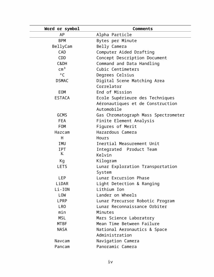
Figure 1: Concept Drawing for LOW
1.4.2 Dimensional PropertiesBy using the Atlas V-401 as the launch vehicle for the LETS mission, the LOW is restricted greatly in size. The CDD states that the LETS must be able to fit safely inside the shroud of the launch vehicle. With the shroud being 3.5 meters in diameter, the LOW must be designed accordingly. After lengthy discussion, all the subsystems agreed on the dimensions of the LOW. The LOW is to be 2 meters wide, 1 meter long and 0.5 meters tall. The design of the SRV was also limited by its dimensions. Both height and mass of the SRV also needed to be taken in to consideration. Since the LOW was being designed to travel to all 20 sites, the LOW needed to be designed in a way to avoid mission failure. With the center of gravity located at the center of the LOW, the SRV needed to be designed in a way to minimize the chances of the LOW tipping over. Team Eclipse limited ESTACA to a SRV of 200 kilograms and no higher than 2.5 meters tall. The dimensions of the LOW can be seen in Appendix E.
1.4.3 Operations ScenarioThe Operations Scenario is a list of day to day activities for the Rover. Upon completing the Terminal Descent Phase (TDP), the LOW will depart from the landing platform, drop an electronic equipment box to achieve the single site goals, and make its way to the second test site. Traveling at an average speed of 4 meters per hour, the LOW will take approximately 7 days to get to the next test site. Upon reaching the test site, the LOW will began scientific experimentation. Also if in line of sight to the LRO, the LOW will send data via an S-Band antenna. Please see Appendix J for all activities of the LRO.
5
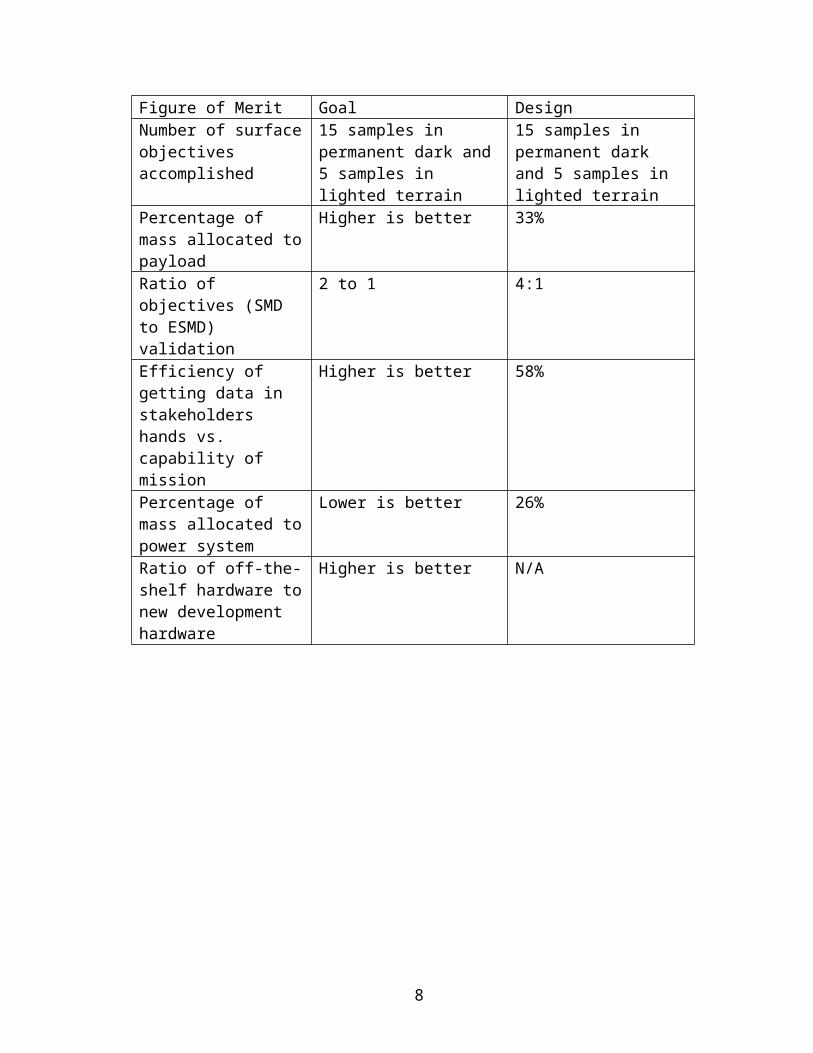
1.5 The Performance1.5.1 LETS Figures of MeritThe following table shows the Figures of Merit that were given to Team Eclipse in the beginning of the semester.
Table 2: Figures of MeritFigure of Merit Goal DesignNumber of surface objectives accomplished
15 samples in permanent dark and 5 samples in lighted terrain
15 samples in permanent dark and 5 samples in lighted terrain
Percentage of mass allocated to payload
Higher is better 33%
Ratio of objectives (SMD to ESMD) validation
2 to 1 4:1
Efficiency of getting data in stakeholders hands vs. capability of mission
Higher is better 58%
Percentage of mass allocated to power system
Lower is better 26%
Ratio of off-the-shelf hardware to new development hardware
Higher is better N/A
6
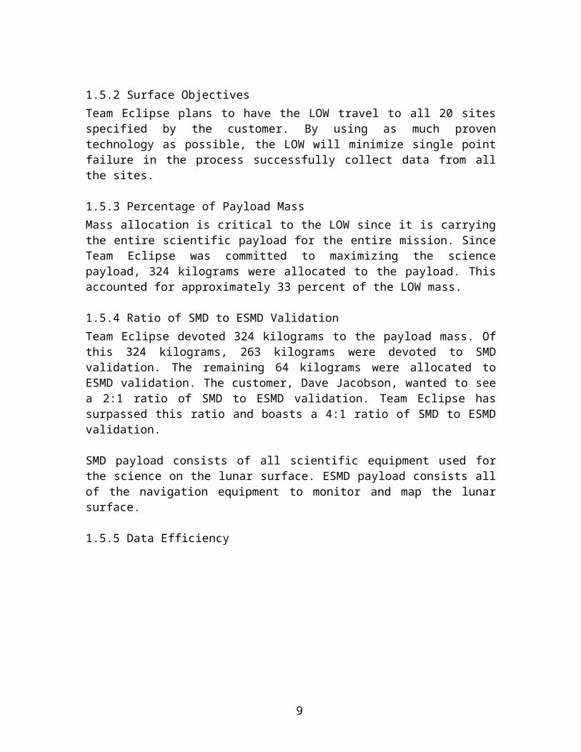
1.5.2 Surface ObjectivesTeam Eclipse plans to have the LOW travel to all 20 sites specified by the customer. By using as much proven technology as possible, the LOW will minimize single point failure in the process successfully collect data from all the sites.
1.5.3 Percentage of Payload MassMass allocation is critical to the LOW since it is carrying the entire scientific payload for the entire mission. Since Team Eclipse was committed to maximizing the science payload, 324 kilograms were allocated to the payload. This accounted for approximately 33 percent of the LOW mass.
1.5.4 Ratio of SMD to ESMD ValidationTeam Eclipse devoted 324 kilograms to the payload mass. Of this 324 kilograms, 263 kilograms were devoted to SMD validation. The remaining 64 kilograms were allocated to ESMD validation. The customer, Dave Jacobson, wanted to see a 2:1 ratio of SMD to ESMD validation. Team Eclipse has surpassed this ratio and boasts a 4:1 ratio of SMD to ESMD validation.
SMD payload consists of all scientific equipment used for the science on the lunar surface. ESMD payload consists all of the navigation equipment to monitor and map the lunar surface.
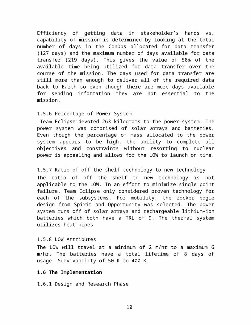
1.5.5 Data EfficiencyEfficiency of getting data in stakeholder’s hands vs. capability of mission is determined by looking at the total number of days in the ConOps allocated for data transfer (127 days) and the maximum number of days available for data transfer (219 days). This gives the value of 58% of the available time being utilized for data transfer over the course of the mission. The days used for data transfer are still more than enough to deliver all of the required data back to Earth so even though there are more days available for sending information they are not essential to the mission.
1.5.6 Percentage of Power System Team Eclipse devoted 263 kilograms to the power system. The power system was comprised of solar arrays and batteries. Even though the percentage of mass allocated to the power system appears to be high, the ability to complete all objectives and constraints without resorting to nuclear power is appealing and allows for the LOW to launch on time.
1.5.7 Ratio of off the shelf technology to new technologyThe ratio of off the shelf to new technology is not applicable to the LOW. In an effort to minimize single point failure, Team Eclipse only considered proven technology for each of the subsystems. For mobility, the rocker bogie design from Spirit and Opportunity was selected. The power system runs off of solar arrays and rechargeable lithium-ion batteries which both have a TRL of 9. The thermal system utilizes heat pipes
7
1.5.8 LOW AttributesThe LOW will travel at a minimum of 2 m/hr to a maximum 6 m/hr. The batteries have a total lifetime of 8 days of usage. Survivability of 50 K to 400 K
1.6 The Implementation
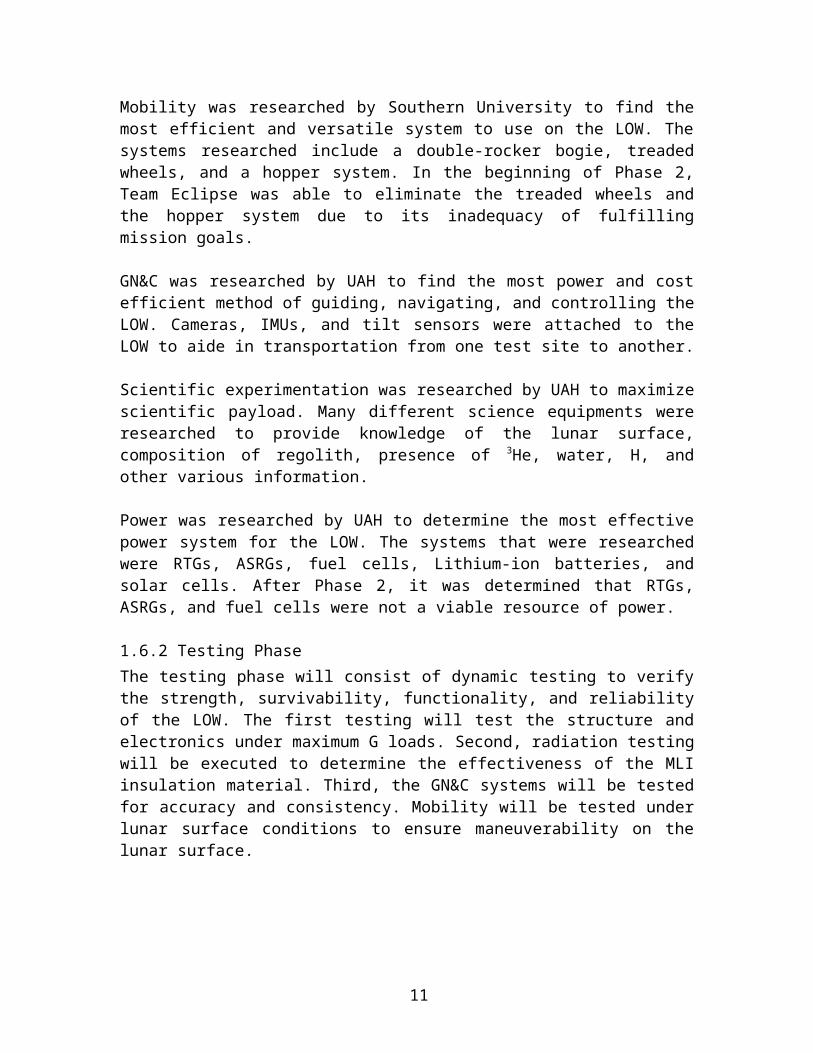
1.6.1 Design and Research PhaseMobility was researched by Southern University to find the most efficient and versatile system to use on the LOW. The systems researched include a double-rocker bogie, treaded wheels, and a hopper system. In the beginning of Phase 2, Team Eclipse was able to eliminate the treaded wheels and the hopper system due to its inadequacy of fulfilling mission goals.
GN&C was researched by UAH to find the most power and cost efficient method of guiding, navigating, and controlling the LOW. Cameras, IMUs, and tilt sensors were attached to the LOW to aide in transportation from one test site to another.
Scientific experimentation was researched by UAH to maximize scientific payload. Many different science equipments were researched to provide knowledge of the lunar surface, composition of regolith, presence of 3He, water, H, and other various information.
Power was researched by UAH to determine the most effective power system for the LOW. The systems that were researched were RTGs, ASRGs, fuel cells, Lithium-ion batteries, and solar cells. After Phase 2, it was determined that RTGs, ASRGs, and fuel cells were not a viable resource of power.
1.6.2 Testing PhaseThe testing phase will consist of dynamic testing to verify the strength, survivability, functionality, and reliability of the LOW. The first testing will test the structure and electronics under maximum G loads. Second, radiation testing will be executed to determine the effectiveness of the MLI insulation material. Third, the GN&C systems will be tested for accuracy and consistency. Mobility will be tested under lunar surface conditions to ensure maneuverability on the lunar surface.
A second LOW will be developed as a terrestrial test for all systems while the LOW is in mission on the lunar surface. Command controls will initially be sent to the terrestrial LOW to determine acceptability of command controls. If the terrestrial LOW accepts the command controls without a glitch, then those controls will be sent to the lunar LOW
1.6.3 ImplementationAfter extensive research, Team Eclipse determined that the best mobility system to use on the LOW was the double-rocker bogie system due to availability and effectiveness for the mission goals.
8
After extensive research, Team Eclipse determined that the most effective way of traveling on the lunar surface is with the use of navigational digital imaging devices, radars, LiDAR, sensors, and trackers.
A major selling point of Team Eclipse’s LOW mission is to maximize scientific payload. With that in mind, additional scientific instrumentation, in addition to equipment mentioned in the CDD, was added to the LOW. Such instrumentation includes 3He sensors, UV imaging, IR bolometer, etc.
At the end of Phase 2, Team Eclipse dismissed the idea of using RTGs or ASRGs due to the lack of material needed and the time required to develop an RTG or ASRG system. During Phase 3, it was determined that fuel cells were not a viable source of power because of electrolysis. Electrolysis has not been tested in spaceflight, and therefore is not a desired readiness level. Therefore, the power source chosen for the LOW are solar cells, and the power storage is Li-ion batteries.
2.0 Technical Description of Methods Used
2.1 OverviewIn this section of the report, each subsystem will be discussed and how it contributed to the design of the LOW. In each section, the methodologies of a particular subsystem will be discussed in detail along with any assumptions made during the course of the design process. Any conclusions and design implications concerning a particular subsystem are discussed in this section of the report. The main purpose of this section is to provide a detailed overview of Team Eclipse’s LOW concept from a technical standpoint along with the steps taken to reach the final product.
2.2 Project OfficeThe Project Office was expected to oversee and manage the team at all times during the design process. The Project Office was expected to communicate design concerns with the customer as well as ensuring the final design conformed to the requirements stated in the CDD. Along with managing the team, the Project Office was to make sure the team stayed on a consistent design path in order to utilize time efficiently. Managing team dynamics fell directly on the Project Office. If a dispute between two or more team members arose, the Project Office was expected to step in and resolve the issue to the best of their ability.
9
There were a few issues discovered during the course of the design process. The first major design issue occurred during phase three. After presenting to the review board culminating phase two, Team Eclipse was ready to begin a more in-depth analysis of the chosen concept, the LOW. Early on, Power learned that using the RTGs Team Eclipse had chosen would be nearly impossible for two blatant reasons. The first and biggest reason was the lack of Plutonium-238 in the United States. Team Eclipse had initially planned on using two RTGs to provide power to the LOW for the extent of the mission. This would inherently require a rather large amount of Plutonium that the United States would not be able to supply. The second problem Team Eclipse found with using RTGs was the given launch date in the CDD. The LETS was expected to launch NLT September 30, 2012. This was important, because it was discovered that RTGs take at least five years to procure. With no RTGs currently being developed by the United States, Team Eclipse realized it would be impossible to meet the given launch date and utilize nuclear power. The Project acted and called a team meeting to present the problem to the team and decide on an alternative power source. Team Eclipse came to the conclusion that the LOW would run off of solar arrays and Lithium-ion batteries.
The only other design issue was relatively minor. Early on in phase three, Team Eclipse discovered a potential problem concerning the mobility system. By picking the LOW concept to move into Phase 3, the team was taking a big risk with single point failure. With Southern University (SU) already analyzing mobility systems from previous missions, Team Eclipse decided the mobility system of choice was a rocker bogie suspension system similar to the one on MSL. The reasoning behind this was that since single point failure was a major issue with the LOW design, Team Eclipse needed to utilize as much proven technology as possible. With the rocker bogie having a TRL level of nine, Team Eclipse was very biased towards this design. The team felt given the rocker bogie’s robust design and proven success on both Spirit and Opportunity this was the mobility system that needed to be utilized on the LOW. The Project Office immediately informed SU of the team’s decision and the design process continued onward.
2.3 Systems Engineering
10
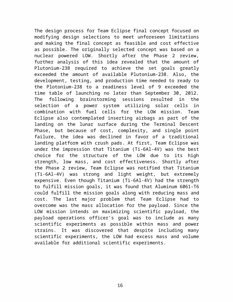
The design process for Team Eclipse final concept focused on modifying design selections to meet unforeseen limitations and making the final concept as feasible and cost effective as possible. The originally selected concept was based on a nuclear powered LOW. Shortly after the Phase 2 review, further analysis of this idea revealed that the amount of Plutonium-238 required to achieve the set goals greatly exceeded the amount of available Plutonium-238. Also, the development, testing, and production time needed to ready to the Plotonium-238 to a readiness level of 9 exceeded the time table of launching no later than September 30, 2012. The following brainstorming sessions resulted in the selection of a power system utilizing solar cells in combination with fuel cells for the LOW mission. Team Eclipse also contemplated inserting airbags as part of the landing on the lunar surface during the Terminal Descent Phase, but because of cost, complexity, and single point failure, the idea was declined in favor of a traditional landing platform with crush pads. At first, Team Eclipse was under the impression that Titanium (Ti-6Al-4V) was the best choice for the structure of the LOW due to its high strength, low mass, and cost effectiveness. Shortly after the Phase 2 review, Team Eclipse was notified that Titanium (Ti-6Al-4V) was strong and light weight, but extremely expensive. Even though Titanium (Ti-6Al-4V) had the strength to fulfill mission goals, it was found that Aluminum 6061-T6 could fulfill the mission goals along with reducing mass and cost. The last major problem that Team Eclipse had to overcome was the mass allocation for the payload. Since the LOW mission intends on maximizing scientific payload, the payload operations officer’s goal was to include as many scientific experiments as possible within mass and power strains. It was discovered that despite including many scientific experiments, the LOW had excess mass and volume available for additional scientific experiments.
Therefore, the final design is a Lander on Wheels utilizing solar and fuel cells and attached with a landing platform with crush pads to help negotiate unexpected landing slopes. The landing platform’s structure consists of the Aluminum 6061-T6. With respect to mass allocation for the payload, more scientific instrumentation was added to the LOW to further maximize scientific payload.
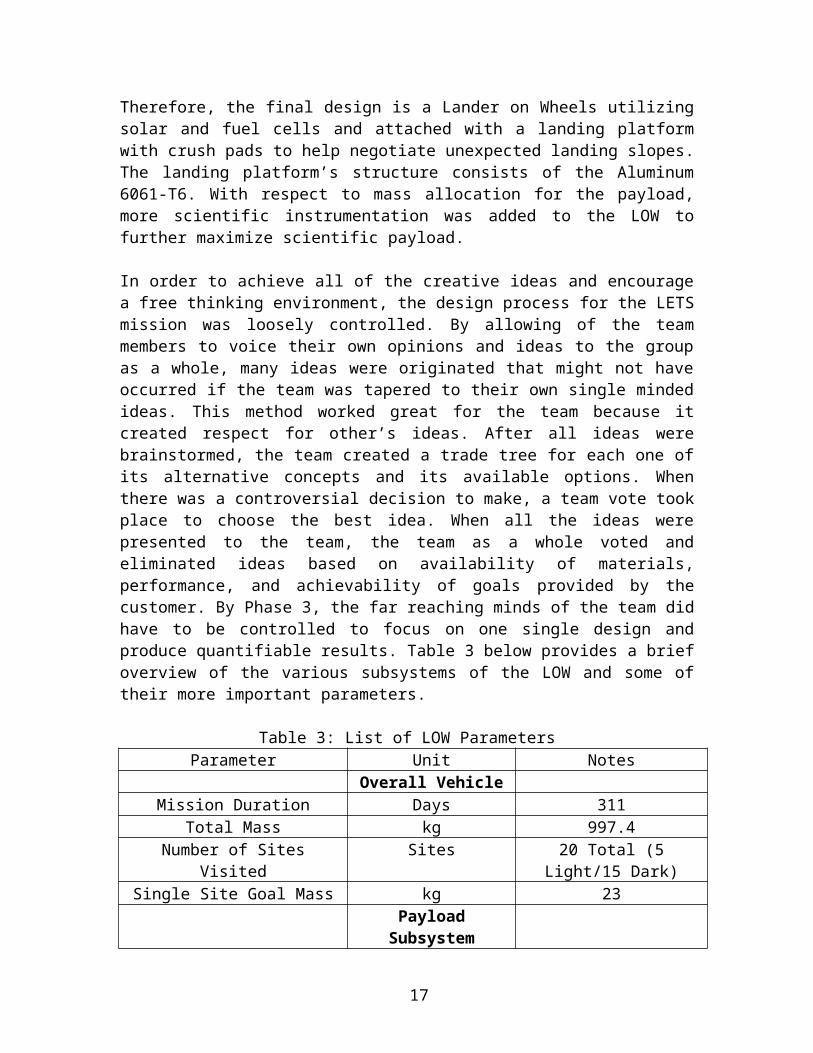
In order to achieve all of the creative ideas and encourage a free thinking environment, the design process for the LETS mission was loosely controlled. By allowing of the team members to voice their own opinions and ideas to the group as a whole, many ideas were originated that might not have occurred if the team was tapered to their own single minded ideas. This method worked great for the team because it created respect for other’s ideas. After all ideas were brainstormed, the team created a trade tree for each one of its alternative concepts and its available options. When there was a controversial decision to make, a team vote took place to choose the best idea. When all the ideas were presented to the team, the team as a whole voted and eliminated ideas based on availability of materials, performance, and achievability of goals provided by the customer. By Phase 3, the far reaching minds of the team did have to be controlled to focus on one single design and produce quantifiable results. Table 3 below provides a brief overview of the various subsystems of the LOW and some of their more important parameters.
11
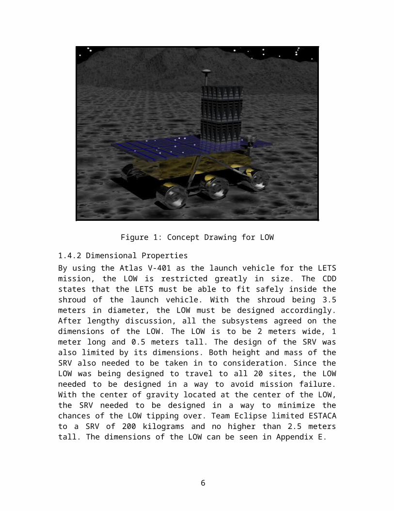
Table 3: List of LOW ParametersParameter Unit Notes
Overall VehicleMission Duration Days 311
Total Mass kg 997.4Number of Sites Visited Sites 20 Total (5 Light/15 Dark)Single Site Goal Mass kg 23
Payload SubsystemTotal Mass kg 324SMD Mass kg 260
ESMD Mass kg 64Payload Percentage of
Total Mass kg 32.48 %
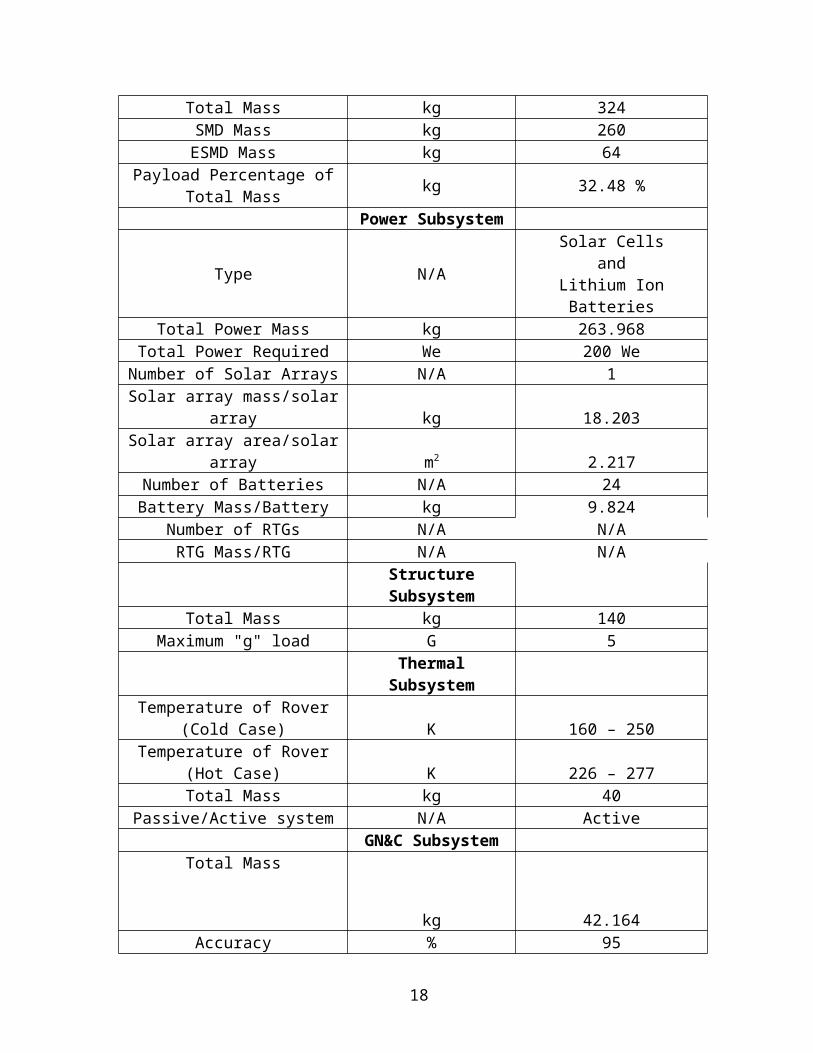
Power Subsystem
Type N/ASolar Cells
andLithium Ion Batteries
Total Power Mass kg 263.968Total Power Required We 200 We
Number of Solar Arrays N/A 1Solar array mass/solar array kg 18.203Solar array area/solar array m2 2.217
Number of Batteries N/A 24Battery Mass/Battery kg 9.824
Number of RTGs N/A N/ARTG Mass/RTG N/A N/A
Structure SubsystemTotal Mass kg 140
Maximum "g" load G 5Thermal Subsystem
Temperature of Rover (Cold Case) K 160 – 250
Temperature of Rover (Hot Case) K 226 – 277Total Mass kg 40
Passive/Active system N/A ActiveGN&C Subsystem
Total Mass kg 42.164Accuracy % 95
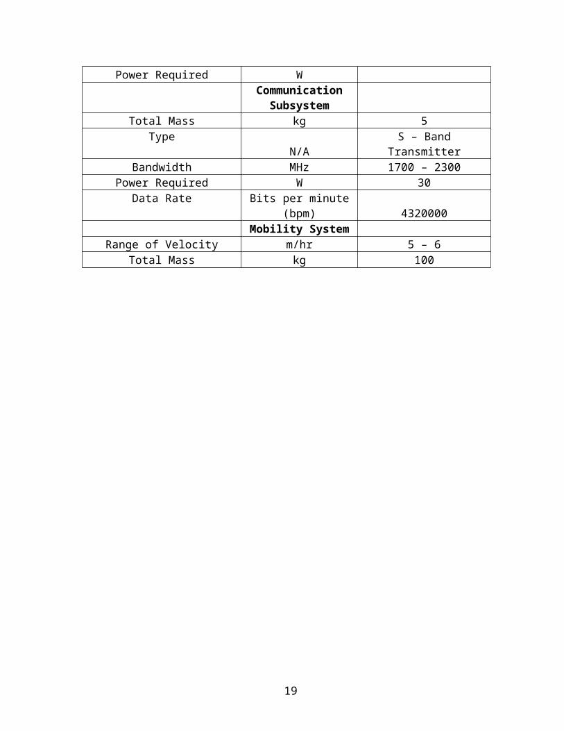
Power Required WCommunication
SubsystemTotal Mass kg 5
12
Type N/A S – Band TransmitterBandwidth MHz 1700 – 2300
Power Required W 30Data Rate Bits per minute (bpm) 4320000
Mobility SystemRange of Velocity m/hr 5 – 6
Total Mass kg 100
13
2.4 Power
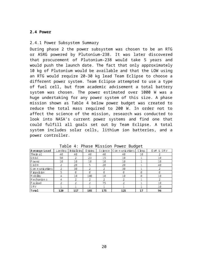
2.4.1 Power Subsystem SummaryDuring phase 2 the power subsystem was chosen to be an RTG or ASRG powered by Plutonium-238. It was later discovered that procurement of Plutonium-238 would take 5 years and would push the launch date. The fact that only approximately 10 kg of Plutonium would be available and that the LOW using an RTG would require 20-30 kg lead Team Eclipse to choose a different power system. Team Eclipse attempted to use a type of fuel cell, but from academic advisement a total battery system was chosen. The power estimated over 1000 W was a huge undertaking for any power system of this size. A phase mission shown as Table 4 below power budget was created to reduce the total mass required to 200 W. In order not to affect the science of the mission, research was conducted to look into NASA’s current power systems and find one that could fulfill all goals set out by Team Eclipse. A total system includes solar cells, lithium ion batteries, and a power controller.
Table 4: Phase Mission Power Budget
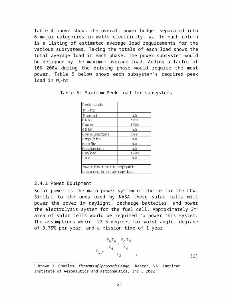
Table 4 above shows the overall power budget separated into 6 major categories in watts electricity, We. In each column is a listing of estimated average load requirements for the various subsystems. Taking the totals of each load shows the total average load in each phase. The power subsystem would be designed by the maximum average load. Adding a factor of 10% 200W during the driving phase would require the most power. Table 5 below shows each subsystem’s required peek load in We-hr.
Table 5: Maximum Peek Load for subsystems
14
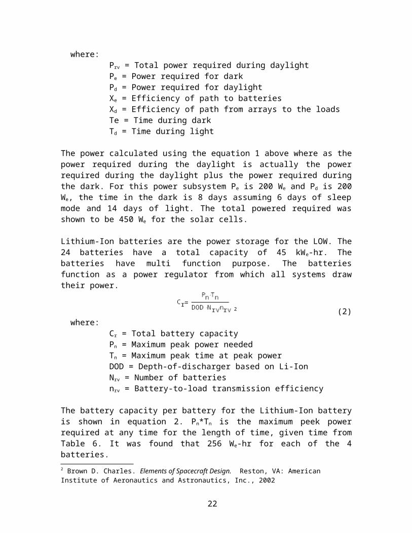
2.4.2 Power EquipmentSolar power is the main power system of choice for the LOW. Similar to the ones used by NASA these solar cells will power the rover in daylight, recharge batteries, and power the electrolysis system for the fuel cell. Approximately 3m2 area of solar cells would be required to power this system. The assumptions where: 23.5 degrees for worst angle; degrade of 3.75% per year, and a mission time of 1 year.
1 (1)where:
Prv = Total power required during daylightPe = Power required for darkPd = Power required for daylightXe = Efficiency of path to batteriesXd = Efficiency of path from arrays to the loadsTe = Time during darkTd = Time during light
The power calculated using the equation 1 above where as the power required during the daylight is actually the power required during the daylight plus the power required during the dark. For this power subsystem Pe is 200 We and Pd is 200 We, the time in the dark is 8 days assuming 6 days of sleep mode and 14 days of light. The total powered required was shown to be 450 We for the solar cells.
Lithium-Ion batteries are the power storage for the LOW. The 24 batteries have a total capacity of 45 kWe-hr. The batteries have multi function purpose. The batteries function as a power regulator from which all systems draw their power.
1 Brown D. Charles. Elements of Spacecraft Design. Reston, VA: American Institute of Aeronautics and Astronautics, Inc., 2002
15
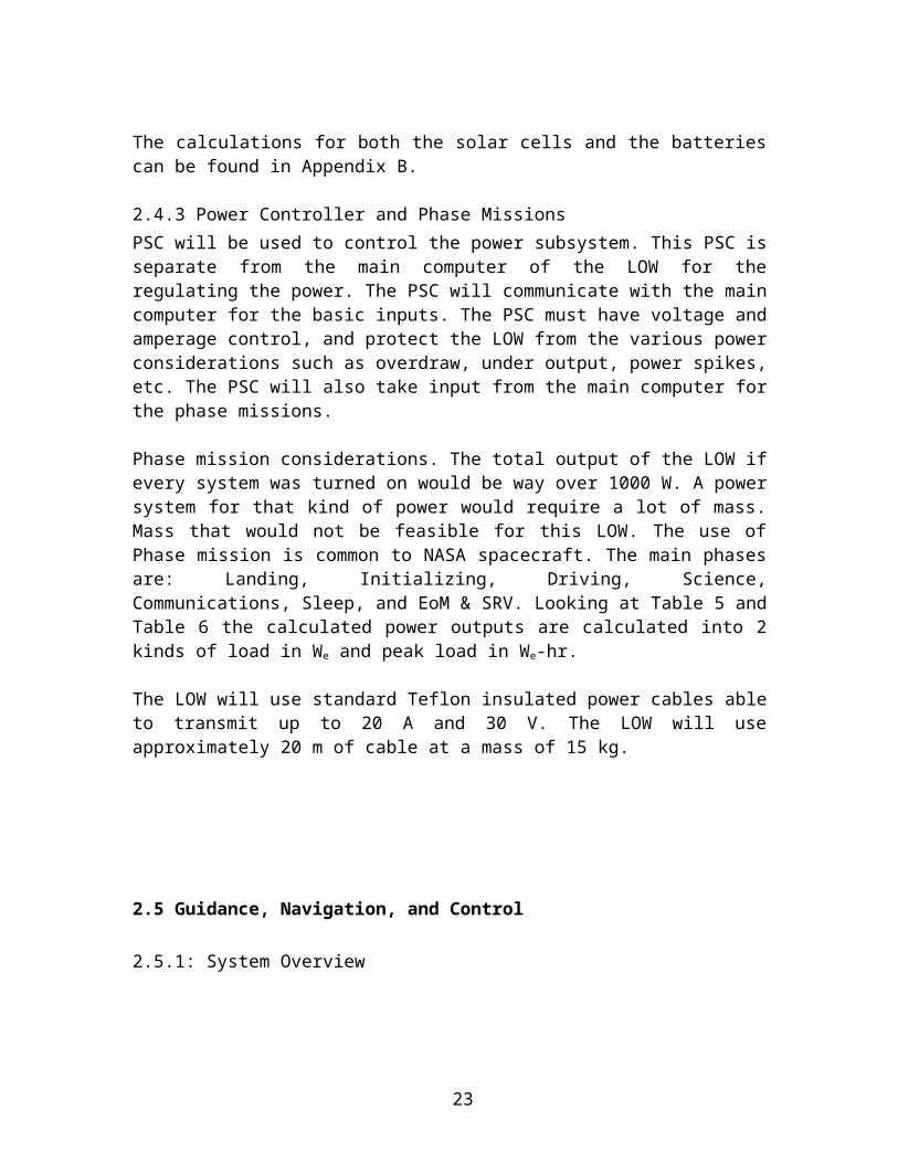
2 (2)
2 Brown D. Charles. Elements of Spacecraft Design. Reston, VA: American Institute of Aeronautics and Astronautics, Inc., 2002
16
where:Cr = Total battery capacityPn = Maximum peak power neededTn = Maximum peak time at peak powerDOD = Depth-of-discharger based on Li-IonNrv = Number of batteriesnrv = Battery-to-load transmission efficiency
The battery capacity per battery for the Lithium-Ion battery is shown in equation 2. Pn*Tn
is the maximum peek power required at any time for the length of time, given time from Table 6. It was found that 256 We-hr for each of the 4 batteries.
The calculations for both the solar cells and the batteries can be found in Appendix B.
2.4.3 Power Controller and Phase MissionsPSC will be used to control the power subsystem. This PSC is separate from the main computer of the LOW for the regulating the power. The PSC will communicate with the main computer for the basic inputs. The PSC must have voltage and amperage control, and protect the LOW from the various power considerations such as overdraw, under output, power spikes, etc. The PSC will also take input from the main computer for the phase missions.
Phase mission considerations. The total output of the LOW if every system was turned on would be way over 1000 W. A power system for that kind of power would require a lot of mass. Mass that would not be feasible for this LOW. The use of Phase mission is common to NASA spacecraft. The main phases are: Landing, Initializing, Driving, Science, Communications, Sleep, and EoM & SRV. Looking at Table 5 and Table 6 the calculated power outputs are calculated into 2 kinds of load in We and peak load in We-hr.
The LOW will use standard Teflon insulated power cables able to transmit up to 20 A and 30 V. The LOW will use approximately 20 m of cable at a mass of 15 kg.
17
2.5 Guidance, Navigation, and Control
2.5.1: System OverviewIn spatial terms, guidance is assisting a spacecraft in a desired direction of travel, navigation is establishing knowledge of the spacecraft’s position in order to properly arrive at a desired location, and control is making sure the spacecraft will travel in a desired direction to a desired location. The Lander on Wheels guidance, navigation, and control (GN&C) subsystem provides for both the landing sequence, or the Terminal Descent Phase (TDP) and lunar maneuvering, or the Lunar Excursion Phase (LEP). It has three primary subsystems: attitude control (sensors/actuators) subsystem (ACS), computer subsystem (CSS), and an optics subsystem (OSS). During both phases, all three subsystems will come into play. Both phases will incorporate some form of GN&C.
2.5.2: Terminal Descent PhaseSince the LETS mission starts at 5km above the lunar surface, several issues must be considered in the way of terminal descent. During the Terminal Descent Phase, the LOW will rely on several onboard instruments to help guide, navigate, and control it to a safe and precise landing on the lunar surface. Those instruments shall be made up of a sensor suite of Inertial Measurement Units (IMU), a Star Tracker, sun sensors, optical remote sensing/imaging device, a radar altimeter, a scanning laser rangefinder/topographical decipherer (Light Detection and Ranging, or LiDAR), and actuators. A guidance computer will also be used during descent and shall be discussed in detail immediately following the Lunar Excursion Phase summary below. The instruments will be strategically placed aboard the lander as determined by the customer in order to achieve the full effect of the instruments’ capabilities.
18
The inertial measurement unit is equipped with sensors (three gyros and accelerometers - one set for each axis) to measure the spacecraft’s inertial acceleration, or G-Forces, and rotational rates (roll, pitch, and yaw) and then relays this information to a guidance computer which then ultimately determines the position and velocity of the vehicle. The guidance computer has the capability of determining the position and velocity through process known as dead reckoning3. Dead reckoning is a centuries-old method of navigation used to determine one’s location primarily based off of a reference location. The computer establishes this reference location via other sensors equipped on the LOW which are discussed in the subsequent paragraphs. The IMU of choice will be Northrop Grumman’s LN-200 fiber optic inertial measurement unit, which has been proven in use by satellites (i.e. Clementine), missiles (i.e. AGM-142 Raptor), and even military aircraft (i.e. RQ-4 Global Hawk)4. The highly reliable LN-200 will provide extremely accurate and precise attitude readings for the Lander on Wheels to allow for spacecraft stabilization during the Terminal Descent Phase. Pertinent specifications of the LN-200 can be seen in Appendix C.
Star Trackers are supplemental to the inertial measurement units in that they provide highly accurate inertial attitude measurements that are required to update the IMU periodically via an IMU alignment to correct IMU drift5. Star trackers are a key component to the attitude control subsystem, as they make up for the possible accumulated drift errors created by the IMU. The wide field-of-view Star Tracker will output an inertial-to-body quaternion, which is used to telemeter the spacecrafts current attitude. A quaternion is basically a mathematical notation for representing orientations and rotations of the spacecraft, which means the data output is typically quite efficient and stable6. The Goodrich HD-1003 will be the Star Tracker of choice primarily due to the fact that “Goodrich Electro-Optical Systems is the world leader in the design and manufacture of star trackers, with extensive flight experience in high-radiation orbital environments”7. The HD-1003 is capable of simultaneously tracking 6 stars at any moment and then using them as a reference to determine the lander’s orientation in space. All data for the Goodrich HD-1003 can be seen in Appendix C.
3 http://en.wikipedia.org/wiki/Inertial_Measurement_Unit4 http://www.es.northropgrumman.com/solutions/ln200/assets/Inertial_Measurement_Unit_LN-2.pdfLN-200 Fiber Optic Inertial Measurement Unit5 http://science.ksc.nasa.gov/shuttle/technology/sts-newsref/sts-gnnc.htmlGuidance, Navigation, and Control. Updated 8/31/006 Quaternions and rotation Sequences: a Primer with Applications to Orbits, Aerospace, and Virtual Reality. Kuipers, Jack B., Princeton University Press copyright 19997 http://www.oss.goodrich.com/datasheets/oss/Goodrich_HD1003_StarTracker.pdf HD-1003 Star Tracker Attitude Sensor. 2004
19
The sun sensors will also contribute to the attitude determination of the LOW, and will supplement the Star Tracker and IMU. Sun sensors work by quantifying the amount of light or shadow cast on the spacecraft at any given point in time, which in turn determines its orientation with respect to the sun8. The sun sensors to be used on the LOW are developed by Optical Energy Technology. Their dual-axis sun sensors (Model 0.5) use algorithms to communicate to the LOW’s guidance computer with high accuracy. See Appendix C for relevant sun sensor data.
8 http://www.agi.com/downloads/corporate/partners/edu/advancedSunSensorProject.pdf Attitude Determination – Advanced Sun Sensors for Pico-satellites.
20
To accommodate for the precise landing requirement, high precision landing site mapping techniques shall be employed. This will be accomplished by way of a digitized view of the land area acquired onboard the lander (during descent) which are then compared and matched with images which are preloaded in the memory of the guidance computer to guide the LOW to its precise landing location. Said stored images are to be obtained from the successful mission of the 1994 Clementine satellite, whose secondary objective was to completely map the lunar surface while orbiting the moon9. This type of non-GPS based navigation is similar to the precision guided missile navigation systems currently in use today (i.e. Tomahawk land-attack cruise missile). An instrument that carries this type of navigational capabilities is the Raytheon AN/DXQ-1 DSMAC IIA (Digital Scene Matching Area Correlator), and will be used on the LOW. The photographs it obtains during the Terminal Descent Phase will be matched up with like images stored in the guidance computer’s database for a more accurate landing capability of the LOW. The reason for it providing an accurate landing ability is due to the fact that any deviations in images will lead to an automated course correction induced by the DSMAC system. Currently, it is difficult to obtain a wealth of specification data on a DSMAC system due to its proprietary nature, however, because of its proven flight heritage and capabilities, the off-the-shelf technology should have a high readiness level.
DSMAC is not capable of gaining useful contour and topographical information, therefore, LiDAR will also be employed on the Lunar Lander. During terminal descent, the LiDAR guidance system will be used to objectively view the moon’s topography and be able to determine whether or not the terrain beneath the LOW is sloped and/or hazardous. It will use sensors combined with onboard computing to detect hazards in the landing zone and autonomously select a location that is reachable and safe. A slight drawback, however, to the LiDAR system is that the frequency of the laser scattering on the lunar surface (particularly due to extreme surface temperatures) may provide inaccurate readings of surface topography. The landing LiDAR of choice will be the MDA(MacDonald, Dettwiler, and Associates, Ltd.)-Optech LiDAR, primarily because it has proven flight heritage in space onboard the Air Force’s XSS-11 satellite. Being that this particular LiDAR system is space qualified, the extreme surface temperatures of the moon may present a non-issue, thus allowing the LiDAR to produce effective readings. Data pertaining to the MDA-Optech LiDAR is scarce (possibly due to its proprietary uses), however, some can be found in Appendix C.
9 https://www.llnl.gov/etr/pdfs/06_94.1.pdfThe Clementine Satellite. June 1994
21
To get a better idea of the altitude above the terrain beneath the spacecraft at any given time, a radar altimeter will be used. The radar altimeter will be used in conjunction with the LiDAR system as a supplemental device. The concept of a radar altimeter is simple: radio waves are transmitted towards the surface below, and then reflected back to the spacecraft once the surface is reached, and, knowing the speed of the radio wave, the time it takes for the altimeter to receive the signal corresponds to a certain distance, or altitude. Many radar altimeters were considered, however the Honeywell HG-8500 will be the one used in the LOW. It specializes in altitude determination of remotely piloted vehicles and tactical targets10; therefore, it suits the LETS mission perfectly. Specifications for the HG-8500 can be seen in Appendix C.
Lastly, actuated descent of the vehicle during the landing sequence will primarily be done via two MR-80B monopropellant hydrazine liquid rocket engines and 12 MR-106 monopropellant thrusters provided by the customer. Secondarily, reaction wheels will be used during controlled powered descent. They will be used to provide an external force, or torque, to assist the ACS thrusters. The torque produced will be capable of changing the spacecraft’s angular momentum. They can be used to offset zero-mean torques on the LOW without the consumption of the hydrazine fuel and can store momentum induced by very low frequency or DC torques. In addition to assisting the ACS, reaction wheels can aid large slewing (swinging or veering) maneuvers during descent11. Ithaco Type-A reaction wheels will be utilized on the lunar lander, specifications of which can be found in Appendix C.
2.5.3: Excursion PhaseDuring the Lunar Excursion Phase (LEP), the LOW will rely on several instruments to assist in navigating/traversing the lunar surface successfully and effectively. These instruments will be comprised of one of the IMU’s used during the Terminal Descent Phase, a tilt sensor, several cameras strategically placed on the LOW, as well as the same guidance computer used during TDP.
10 http://www51.honeywell.com/aero/common/documents/myaerospacecatalog-documents/MilitaryAC/HG8500_Radar_Altimeter.pdfHoneywell HG8500 Series Radar Altimeter. June 13, 200311 http://trs-new.jpl.nasa.gov/dspace/bitstream/2014/15835/1/00-1598.pdfDevelopment and Validation of Reaction Wheel Disturbance Models: Empirical Model. June 28, 2001
22
Following the same manner of operation as the IMU on the 2003 Mars Exploration Rovers, the LOW IMU (LN-200) shall be used to determine heading and tilt of the rover during a traverse. The gyroscopes within the IMU shall measure small heading changes of the rover with a high level of accuracy. Additionally, the accelerometers will measure where the moon’s gravity is strongest, pulling down on the rover12. This is useful due to the fact that if the rover knows where gravity is, it can, to a certain extent, evaluate its orientation on the surface. Furthermore, the rover will be equipped with 2 tilt sensors to gain knowledge of the angle of inclination the rover is positioned at any moment in time. These sensors will relay the relevant information to the guidance computer, allowing it to make course adjustments if necessary. The tilt sensor of choice will be Seika’s NG3 Inclinometer, primarily because of its high accuracy and robust design. Design specifications of the NG3 can be seen in Appendix C.
Cameras
The LOW will be equipped with eight cameras to assist in the Excursion Phase. The LOW will have panoramic cameras (PanCams), navigational cameras (NavCams), hazard avoidance cameras (HazCams), and a belly camera(BellyCam) that have been proven to operate successfully in a space environment. The cameras will be positioned around the vehicle for optimum viewing capability. The NavCams and PanCams will provide terrain data in order for the rover to pass through a charted course. The HazCams will provide image data for the onboard systems to detect and devise an optimal course correction through hazardous terrain. These cameras were selected for their small size, modest power consumption, and, most importantly, the ability to disable automatic exposure.
The manner in which the cameras will assist in traversing the lunar surface will work in the same way the cameras helped the Mars Exploration Rovers maneuver about the Martian surface. Images taken from the rover’s cameras will be analyzed quickly by engineers on earth via communications. Then a target location will be selected based on scientific merit, traverse options will be assessed, and the rover will be commanded to drive to the designated target. In order for engineers, who directed the initial command, to verify if the rover has indeed ended at the desired location, additional image data will be examined. To illustrate, a comparison of the similar features found in the images from the new location (post-traverse) with the images from the original commanded location will provide engineers with enough knowledge to know if the rover actually arrived at the intended area13.
These cameras have been determined to have operating temperature ranges between -55ºC and 22 ºC (but can survive between -120 ºC and 70 ºC). Each camera needs a start-up power of 2.7 watts. After the warm-up the cameras can operate continuously between 2W and 3W. Each cam can digitize 12bits/pixel and has a transfer rate of 5.12ms. The total mass of the cameras is 2.21 kilograms. The total powered to run each camera (simultaneously) is 15.05 watts.12 http://mars.jpl.nasa.gov/mer/mission/tl_surface_nav_balance.htmlRover Navigation During Surface Operations. October 4, 200513 http://www-robotics.jpl.nasa.gov/publications/Mark_Maimone/maki-jgr-2003je002077.pdfMars Exploration Rover Engineering Cameras. Journal of Geophysical Research. 2003
23
The panoramic cameras (PanCam) are high-resolution, stereo cameras developed at the Jet Propulsion Laboratory, and mounted at the top of LOW’s mast along with the NavCam. The PanCams take high-resolution, color images of the surface and surroundings, helping the LOW to select rock and soil targets for intensive examination and to pick new regions for it to explore. When used on the Mars Exploration Rovers, the images from the PanCams created captivating 3-D, 360-degree panoramas of the rovers' different locations. The same will be the case for the LOW’s PanCams. The PanCam boasts 14 different types of filters, allowing for not only full color images but also spectral analysis of minerals and the atmosphere. The camera can also be used to capture images of the Sun to determine each LOW’s exact position and orientation. In a sense, it act’s as a backup for the IMU. A single PanCam can view up to 180°. Each PanCam will be placed onto of the rover and positioned to give an operator a 360° view of the surroundings. The two PanCam eyes are mounted on a mast on the rover deck. The mast is referred to as the PanCam Mast Assembly (PMA). For imaging PanCam uses 1024×2048 pixels. The optical design allows PanCam to maintain optimal focus from infinity to within about 1.5 meters of the cameras. At ranges closer than 1.5 meters, PanCam images suffer from some defocus blur. Each Pamcam weights 270 grams and optimal needed height for the cam to operate is 1.54m above the lunar surface.
The navigational camera (NavCam) is one of two kinds of non-scientific panoramic cameras aboard LOW. A stereo NavCam will assist mission engineers gain a visual impression of the lunar surroundings in grayscale. LOW navigates autonomously part of the time, making its own decisions about where and how to move about the lunar landscape. However the NavCam will provide engineers with a means of visually navigating the terrain if needed. The NavCams weigh 220 grams each and needed to be place 1.54 meters above the lunar surface. Being able to view the surface through the eyes of the rover also allows the engineers to plot necessary course corrections and avoid obstacles that may not already be known.
The hazard cameras (HazCam) are a pair of stereo camera systems designed to image the ground in the immediate vicinity of the LOW to safeguard against the rover getting lost or inadvertently crashing into unexpected obstacles. Mounted in pairs both in front of and behind the LOW, this camera system works in tandem with onboard software, allowing the LOW to make intelligent choices about navigating around hazards. The HazCams will use a broadband visible filter and produce 1024 x 1024 pixel images. The HazCam optics are f-theta fisheye lenses with 124 x 124 degree horizontal/vertical field of view and a 180 degree diagonal field of view. The HazCam optics is f-theta fisheye lenses with 124 x 124 degree horizontal/vertical field of view and a 180° diagonal field of view. Each HazCam weights 245 grams are needed to be placed 0.52 meters above the lunar surface in the front and 0.51 meters in the back. They can also provide terrain context immediately forward and aft of the rover to which the NavCams may not be able to view. The HazCams can also be used to support the arm deployment operations when samples are to be taken and to support rover fine positioning near arm deployment targets14. As stated previously, the LOW is to utilize four HazCams.
14 http://www-robotics.jpl.nasa.gov/publications/Mark_Maimone/maki-jgr-2003je002077.pdf
24
The belly camera (BellyCam) will be mounted directly underneath the rover. Like the other cameras, it is also a stereo camera system. It is designed to image the ground underneath the LOW to safeguard against the rover not having enough ground clearance and inadvertently crashing into unexpected obstacles. Such obstacles could disable the rover from underneath, not allowing the rover to proceed to its destination. The BellyCam also can allow the operator of the drill to gain a visual perspective of the object being drilled. The Bellycam weighs ~215 grams.
Mars Exploration Rover Engineering Cameras. Journal of Geophysical Research. 2003
25
2.5.4 Guidance Computer
In order to receive all pertinent data from the GN&C instruments described in detail above, and then interpret the information, a guidance computer will be a necessary addition aboard the LOW. The design team has chosen BAE Systems RAD750 central processing unit to use high speed interfaces between the varying GN&C instruments. This radiation-hardened single board computer has proven space flight heritage on board about 10 spacecraft, including the Mars Reconnaissance Orbiter and the WorldView-1 Satellite. Because it is well suited for high-radiation environments, it should be a welcome addition to the lander and be able to handle all commands and real-time processing in the lunar setting. As stated above, images taken from the Clementine satellite will be stored within the computer’s 512MB of memory. Moreover, according to BAE, the RAD750’s CPU has 10.4 million CMOS (Complementary metal-oxide-semiconductors) and has a processor speed of up to 200 MHz. General specifications for the BAE RAD750 can be seen in Appendix C.
2.5.5 RedundancyA primary goal for Team Eclipse is to reduce the single point failure of the LOW. The GN&C subsystem will do this by using redundancy. Particularly in the event of a loss of some spacecraft functionality, it is of great importance to be able to regain an equivalent functionality in response. To do this, it is necessary to either include multiple instances of the same mission-critical instrument or have onboard devices that have similar functionality to that instrument. Any backup and/or supplemental instruments will be designed to begin operation immediately after the failure of the originally intended piece of equipment via dual data bus connections. For instance, two inertial measurement units will be onboard the LOW because without an IMU, stability during landing will be quite difficult. A highly reliable Star Tracker will be directly linked to the IMU; therefore, only one will be used. However, it will be dually connected to both IMUs in case of a failure. The IMU links directly to the guidance computer, as well as the tilt sensors used in traversing, the sun sensors and radar altimeter used in descent, the various optical instruments used in both phases, and the actuators. All of the equipment will connected via dual data buses to the guidance computer to make up a primary system, and then a secondary system for backup. To illustrate, if a sun sensor on the primary system fails, but the primary guidance computer is still operational, the secondary sun sensor will be automatically linked to the primary guidance computer. For a visual of the Redundancy control, refer to Appendix C.
2.6 ThermalThe purpose of the thermal control subsystem is to ensure that all of the spacecraft is within an appropriate operating temperature. If particular pieces of equipment are not kept within in appropriate range, then they will not function at optimum levels, and sometimes not operate at all.
26
The first step in selecting equipment for the thermal subsystem is to decide whether or not the system will be active or passive. Generally speaking passive systems are cheaper and lighter and are used for unmanned missions. They can include equipment such as surface finishes, insulation, radiators and louvers. At this point in the design process, both active and passive system components will be utilized. For the active system, heaters will be used.
This mission will be at the pole of the moon, and will encompass its most extreme temperatures. The coldest part of the moon is 50K, while the hottest is 400K.
Since maximizing science is the most important goal in this mission, taking care of the temperature needs of the scientific equipment bears special attention. Another item that has a sensitive temperature range is the batteries. If these are not kept within operating temperature limits, the entire mission will likely fail. Table 6 summarizes the temperature ranges for various equipments.
Table 6: Temperature Ranges for Selected Equipment
Equipment Temperature Range (C)Batteries -10 to 20Electronics 0 to 40Structures -46 to 65Cameras -55 to 295Solar Arrays -100 to 100Power Box Baseplates -10 to 50C& DH Box Baseplates -20 to 60Antennas -100 to 100Mobility -80 to 200
27
Since the mission will be conducted in such a wide range of temperatures, the thermal subsystem must be flexible. It also will have to be able to handle these thermal loads for extended periods of timeTo meet the thermal needs of this mission, a radiator, MLI, and heat pipes will be utilized. It is assumed that the radiator will be mounted on top of the rover, and the heat pipes will be connected to it. This design is being used because mounting sensitive equipment directly to the radiator will likely make it too cold. The connection to the heat pipe will ensure the appropriate temperature levels. Also the rover itself will be wrapped in MLI blankets.
To consider the initial calculations, the rover was assumed to be a 1-meter by 2-meter box. Since the radiator is mounted on top of the rover, it was assumed that it would only see the thermal effects of space, and thus is described by the following equation.
(3)
whereqradiator = Heat dissipated by the radiator, Wσ = Stefan-Boltzmann Constant, 5.67 x 10⁻⁸ W/m2K4
A = Area of radiator, m2
ε = emissivityTradiator = Temperature of radiator, KTspace = Temperature of space, K
In addition to considering the thermal effects of space on the radiator, the effects of the lunar surface on the rover were also considered. To describe this effect, the following equation was used,
(4)
and then solved for the temperature of the rover.
(5)
where,Arover = Area of rover, m2
qrover = heat dissipated by the rover, Wεrover = emissivity of the roverTrover = Temperature of the rover, KFrover = Form factor of the roverFlunar = Form factor of the lunar soil
28
Since the radiator is mounted on top of the rover, it is assumed that it will experience mostly the thermal effects of space. Because of this, it is desirable to have a high emissivity. In Figure 2, the radiator temperature was plotted as a function of emissivity. The purpose of this graph is to correlate a fitting emissivity, radiator temperature at a particular heat dissipation level.
255
275
295
315
335
355
375
395
415
0.5 0.6 0.7 0.8 0.9 1
Emissivity
Tem
p of
Rad
iato
r (K)
0.5 kW
1.0 kW
1.5 kW
2.0 kW
Figure 2: Radiator Temperature as a function of Emissivity
In Figure 3, the temperature of the radiator is plotted as a function of its area. In investigating this graph, one can find a suitable correlation given particular heat dissipation.
29
150
200
250
300
350
400
450
0 5 10 15 20 25
Area (sq. meters)
Rad
iato
r Tem
p (K
)0.5 kW
1.0 kW
1.5 kW
2.0 kW
Figure 3: Radiator Temperature as a function of its Area
The effects of emissivity on the rover also need to be considered, however, in this case, it is desirable to have a low emissivity. In Figure 4, the temperature of the rover was plotted as a function of emissivity. To obtain the cold case, Trover was calculated as in Equation (5) for using the coldest lunar soil temperature Tsoil, which was 40 K.
Cold Case
30
80
130
180
0.04 0.14 0.24 0.34
Emissivity
T of
Rov
er (K
) 50 W
100 W
150 W
200 W
0 W
Figure 4: Temperature of the Rover as a function of Emissivity (Cold Case)
30
In addition to the cold case being considered, the hot case was also examined as shown in Figure 5. Obtaining the hot case was obtained the same way that the cold case. This time Tsoil was 230 K.
Hot Case
208
218
228
238
248
0.04 0.09 0.14 0.19 0.24 0.29 0.34
Emissivity
T of
Rov
er (K
) 50 W
100 W
150 W
200 W
0 W
Figure 5: Temperature of the Rover as a function of Emissivity (Hot Case)
The advantages of heat pipes are numerous, including the ability to deal with a wide temperature range and efficiency. The basic set up of a heat pipe includes an evaporator section, and adiabatic section, and a condenser section. This configuration is shown in Figure 6. The evaporator section of the heat pipe takes in heat externally. This is then conducted through the pipe wall and wick structure, where it vaporizes into the working fluid of the heat pipe. Afterwards, it goes through the adiabatic section and into the condenser section. The heat is then expelled out of the heat pipe via heat sink.
Figure 6: Schematic of heat pipe
31

The purpose of the wick is to return the condensate to the evaporator. There are pores within the wick. Large pores are necessary because it allows for easy movement of fluid through different locations of the heat pipe. There are three properties of wicks that are important to thermal design. They include minimum capillary radius, permeability, and effective thermal conductivity.
The fluid inside of the heat pipe transports the heat taken in the evaporator section by vaporization. It is there necessary to select a fluid that works optimally with the temperature ranges experienced by the spacecraft. It is also necessary to select a fluid that works well with the wick material and the external material of the heat pipe. If a mismatch occurs, then corrosion can occur. The heater will be directly connected to the heat pipes. The heater will use 10 W to heat the LOW during sleep phase.
Other heaters are placed next to the electric motors. The purpose of the heaters will make sure that the mobility system will be able to operate on the dark side of the moon. The mobility system has operation parameters from -80 to 200 ºC. For temperatures below -80 ºC, the heaters will operate as the environment requires. It is also necessary because the rover will be staying on the dark side of the moon for eight days for the science mission, and six days for the sleep phase.
2.7 StructuresThe original configuration of the LOW, from the White Paper, was in a vertical orientation. After detailed examination of payload, power systems, and a final design of the SRV including its launch box, it was determined that the rover can be orientated in a horizontal orientation. The original vertical orientation was originally chosen to maximize the usable volume of the Atlas shroud. However, the total volume needed to house all of the above stated systems is much less than anticipated. By choosing a horizontal rover, the structural requirements and methodology of extrication the rover from the landing platform was greatly simplified.
32
The structural requirements for the landing platform and the rover are as follows. All must withstand a maximum of 5 g’s of acceleration during launch. It is assumed that an adaptor will be designed to attach the landing platform to the shroud of the Atlas launch vehicle that will be able to support the total mass of the LOW. This total mass is estimated to be 976 kg. In addition to launch, the landing platform must be able to survive the semi-hard landing that will occur when it hits the moon’s surface. It is assumed that the propulsion system will cut off when the lander is at an altitude of approximately five meters. With the gravitational acceleration on the moon’s surface (1.64m/s2) being approximately one sixth that of gravity on earth’s surface (9.81m/s2), and assuming that when the propulsion system cuts off, the velocity of the lander is approximately zero, the velocity of the lander when it hits the surface of the moon will be approximately 8.2 meters per second. This impact velocity is significant enough that honey comb crush pads, similar to that of the baseline Viking Lander will be utilized. By utilizing crush pads on the bottom of the lander’s feet and within the main body of the lander legs, it is assumed that ninety percent of the impact force will be absorbed within them. Finite Element Analysis (FEA) was used extensively in designing the structure of the LOW landing platform. Figure 7 shows an FEA analysis on the leg joiner of the landing platform, while Figures 8 and 9 show FEA analysis on the actual legs of the LOW landing structure
33
Figure 7: FEA Analysis on Leg Joiner
25
Figure 8: FEA Analysis of Main Member
26
Figure 9: FEA Analysis of Top of Lander Leg
27
The lander platform is a four leg design that once on the lunar surface will be discarded by the rover. The rover will simply roll off of the platform leaving it behind. To assist in the extrication of the rover from the platform, the lander platform will utilize a small ramp that will be located in the front of the rover. The ramp will be deployed using two small explosive bolts, that when detonated, will cause the ramp to fall. In the event that the ramp does not successfully deploy when the bolts are detonated, most likely due to landing on an incline, the robotic arm of the rover will push the ramp over.
The main structural component of the rover is the body. The body will be constructed of the same titanium that was utilized in the design of the landing legs. The rover body design is a rectangular box with dimensions of 1 meter by 2 meters by approximately .5 meters. The body is designed such that it encapsulates all equipment that must be thermally protected and contains access ports to all scientific equipment that must receive regolith samples from the robotic arm. In addition, the main body is designed to adapt to the six wheel rocker bogie system that Southern University is designing for Mobility and the sample return vehicle (SRV) that ESTACA in designing.
Structures was responsible for ensuring that the mobility system was integrated into the structure of the LOW. Team Eclipse chose the rocker bogie mobility system because of its proven success in mobility systems today and its readiness level. The motors chosen for this mission were the maxon motors that were used on the MER rovers. After taking thermal requirements into consideration, it was determined that these motors would function on the moon. The maxon motors can survive temperature ranges of -80ºC to 204ºC. The mobility system will require separate heaters on each of the independent wheels. These heaters will provide heat to the wheels when the LOW ventures into the dark sites.
2.8 PayloadBased on the design of the rover, the allotted spatial area for the payload will be 2 meters long by 1 meter wide. The Payload will have a mass of 124 kg for equipment + 200 kg for the SRV= 324 kg. This high mass allotment is intended to maximize the scientific equipment, satisfying the minimum scientific experimental requirements as well as including extra equipment for more experimentation. The original payload design used only about 60 kg, but due to availability for greater mass and volume, a more instrumentation was in the design added to maximize experimentation.
The Sample Return Vehicle (SRV) will be used to return samples to the earth. It can be seen in Figures 10 and 11. A launcher for the SRV is positioned at the rear of the LOW, centered at the longitudinal axis. This can be seen in Figures 13 and 14.
37
A photoemission spectrometer and photoelectric cells will be included in order to measure emitted electrons and determine lighting conditions. An emission spectrometer with witness plate will determine regolith composition from micrometeorite impact flashes. A langmuir probe and a particle counter will be used to assess levitation dusts. The LOW will place and leave this equipment on the surface of the moon the first site in order to satisfy the single site goals. Also at the first site, the mast for the imaging system will be deployed on the LOW, and it will remain deployed for the duration of the mission. This equipment is included in a drop box that the LOW will set down while at the first mission site and leave behind. This box includes its own solar panels for power as well as an S-Band transmitter to transmit data. See the Payload appendix for details concerning its power system.
An arm and a scoop will be placed on the right side of the LOW to collect regolith from the lunar surface. The arm may also be used for operating other equipment (See Appendix F). Note that a second arm will be included, but only one is shown in the figures. There will also a drill in order to collect regolith from up to 2 m below the surface. Also on the top of the LOW is a mast that will hold a stereo imaging system to take 360˚ pictures. Cameras on the mast will include those as used on MER (See Figure 14).
Geotechnical experiments will include cone penetrometers, an experimental vane, and a bearing plate to measure lunar soil properties, which can be used to compare soil at the South Pole to that of previous landing sites. The Gas Chromatograph Mass Spectrometer (GCMS) will be used to determine volatile compounds and their composition (such as water, carbon dioxide, hydrogen, etc.). This instrument will use more power than the other instruments; so the GCMS’s power requirement is the deciding factor for maximum power allotment. A neutron spectrometer will be used to determine the flux and energies of neutrons to determine H content of regolith, while magnets placed on the front of the LOW will determine and magnetic susceptibility. XRD/ XRF will be used with an arm, and will determine the mineralogy and chemistry of the regolith. This satisfies the requirements for the instrument package baseline.
Other equipment that will be included in the payload are as here described. A tunable diode laser will be included to determine the presence of water in regolith.15 An electron paramagnetic resonance spectroscope (EPRS) will determine the radioactivity of dust on the moon. An IR bolometer will be included determine surface temperatures. UV imaging will view the lunar surface and the interior of any crater that the LOW may encounter. Helium-3 sensors will allow the LOW to detect the presence of any Helium-3. An alpha particle (AP) spectrometer will determine the presence of alpha particles from gasses below the surface.16 A gamma ray spectrometer will detect thorium and uranium.17 A beacon will be used to as a reference for navigation.
15 http://www.jpl.nasa.gov/news/press_kits/mplds2hq.pdfMars Polar Lander/ Deep Space 2, Press Kit Dec. 199916 http://lunar.arc.nasa.gov/results/alpha.htmALPHA PARTICLE SPECTROMETER - Oct 2, 200117 http://lunar.arc.nasa.gov/results/gamma.htmAn introduction to the gamma ray spectrometer - October 2, 2001
38
Payload figures are on the following pages. See figure 10 & 11 for two views of the SRV, figure 12 for a top-down view of the payload layout, figure 13 for an underside view of the payload, and figure 14 for an isometric view of the LOW.
Figure 10: SRV View 1
39
Figure 11: SRV View 2
40
Figure 12: Top View of Payload without Cover
41Bottom view
Drill not shown.
Figure 13: Bottom View of Payload without Cover
42
Figure 14: Completed CAD Modeling of LOW
2.9 CommunicationThe LOW will utilize a communications subsystem similar to that of the modern day Space Shuttle. The system will consist of a S-Band communication equipment which will be used to transmit data to the LRO and Earth as well at direct LOS.18
The S-Band transmitter will operate in a frequency range of 1700 to 2300 MHz. The system is capable of transmitting 72000 bits per second (bps) to the LRO. However, the LRO will only be at direct LOS for a certain amount of time per orbit, therefore, it will take time to transfer data from the LOW to the LRO. The maximum amount of power that the S-Band transmitter will use is 30 W. Another major selling point for the LOW is that while the LOW is traveling from one test site to another test site, it can transmit data to the LRO. Therefore, the LOW is not only being time efficient, but it also able to multi-task.
18 http://spaceflight.nasa.gov/shuttle/reference/shutref/orbiter/comm/orbcomm/sband.htmlS-Band System Curator: Kim Dismukes | Responsible NASA Official: John Ira Petty | Updated: 04/07/2002Web Accessibility and Policy Notices
43
Data collected from the test sites are stored on a 1 GB hard drive which is located in the belly of the LOW .This storage capacity gives ample room to store test site data and also has more than enough storage space for additional data. Calculations for the time needed to transfer data from the LOW to the LRO at a storage capacity of 300 MB and the transfer rate of 72000 bps can be found in Appendix I.
2.10 Concept of OperationsThe operations subsystem of the LETS is a broad area that encompasses all aspects of the mission. It is the responsibility of this subsystem to ensure that the various other components of the concept can work together in an efficient and effective manner in order to complete the objectives outlined in the Concept Description Document (CDD) for the mission.
The operations component of the Lander on Wheels proposed by Team Eclipse must pay special attention to minimizing single point failure and maximizing scientific payload. Several challenges are associated with these goals such as efficient data storage and careful planning to ensure power for the duration of the mission. These challenges and goals were approached initially by developing a Concept of Operations (ConOps) (Appendix J), which allows a general structure and timeline to be given to the mission. Over the course of the project this ConOps was adjusted to fit the constraints created by the other subsystems.
One of the primary constraints for the mission is power. The LOW has eight days of battery life, which is utilized when the rover travels into dark areas. The LOW also requires fourteen days to replenish the on-board batteries. These factors play a large role in determining the ConOps and the mission timeline.
The course of the mission is through an area along the rim of Shackleton crater and can be seen in Figure 10 below. This region is ideal since there is a well-lit area next to a dark area that makes the travel between charging sites and sample sites as easy as possible. The Shackleton crater site is saved until the end of the mission since it is the most difficult and riskiest to reach. The time designated for travel into the crater is also longer than the travel time between the other sites. This is due to the low lighting conditions even during lunar daytime and the potentially hazardous nature of the terrain. During lunar daytime the LOW will only receive 20-30% of the normal sunlight, which will translate into less available power and slower travel. The schedule outlined in the ConOps is conservative with more time than may be necessary designated for travel. The ConOps is based on a rover speed of five meters per hour, which is slower than the LOW is capable of going but serves the purpose of minimizing the potential for single point failure. This speed still leaves extra time at the end of the mission so the conservative scheduling is not an issue to completing the necessary objectives.
44
The mission can be subdivided into three phases for the purposes of the operations subsystem: landing, exploration, and departure. Each of these phases requires the other subsystems to be coordinated in order to assure mission success. The landing phase requires the Guidance Navigation and Control (GN&C) component to land the LOW within the 300-meter designated landing area. The LOW rover is then removed from the propulsion system via a lowered ramp. This action requires the cooperation of several subsystems including structures, power, GN&C, and thermal. After sending a signal to Earth confirming system readiness, the mission continues to the next phase.
The second operations phase covers exploration of the lunar surface. The schedule and course for this phase is largely driven by the power subsystem since the LOW can only spend eight days in the dark before requiring fourteen days of sunlight to recharge. These timeframes play a large role in the ConOps construction seen in Appendix J. The CDD states that the mission must visit five lit sites and fifteen dark sites including one dark site in the Shackleton Crater. The ConOps outlines the approach taken to ensure that all of these sites are visited within the given timeframe of one year.
Figure 15 below illustrates the path taken by the Lander on Wheels to meet these requirements.
Figure 15: Lunar South Pole Region with Lander on Wheels Mission Course
45
The main challenge in the exploration phase of the mission is remaining efficient while keeping the rover charged for its dark site exploration. It is important to monitor remaining battery charge and ensure that the rover has enough power to reach the light for recharging. Initially, the rover will have fourteen days of sunlight. This is taken advantage of by first exploring lit sites. As the moon becomes dark the rover will switch to battery power and travel into the dark sites. In addition to the power subsystem, structures, GN&C, thermal, and payload will also play roles in this phase of the mission. Data transfer, in particular, is also important during this phase of the mission since any occasion when the Lunar Reconnaissance Orbiter (LRO) passes overhead should be utilized to send information back to Earth. The data needs to be sent often in order to keep the rover’s data storage from becoming full and to ensure acquired data is not lost should there be a mission failure. The time required for the each site’s data to be sent is 5.5 days. This is accounted for in the ConOps seen in Appendix J.
The third and final operations phase is the return phase. During this portion of the mission the Sample Return Vehicle (SRV) will be loaded with all of the samples taken during the exploration phase. The SRV is then sent from the rover to rendezvous with the LRO in orbit around the moon. At that point, the mission is concluded. The return phase is the most critical part since the samples must be returned to Earth in order to be of any value. This phase of the mission requires to cooperation of structures, GN&C, power, thermal, and payload subsystems.
The operations component of the mission supports the main goals of Team Eclipse. The scientific payload is maximized since the schedule allows time for extra sites as well as outlining the simplest method to reach the required sites. The potential for failure is minimized by the conservative nature of the schedule. This allows the LOW to travel at a safe pace and take extra care to avoid hazards.
2.11 Systems InteractionsEach of the subsystems of the LOW need to be taken into account in order for the system to function as a collective whole. Changing one aspect of the LOW system affects the whole design. Therefore there is a sequential nature for the subsystems of the LOW. The following figure below shows the intricate dependency of one system to another. Affecting one of the subsystems will affect another.
See the chart on figure 16, below, for details of subsystem interaction.
46
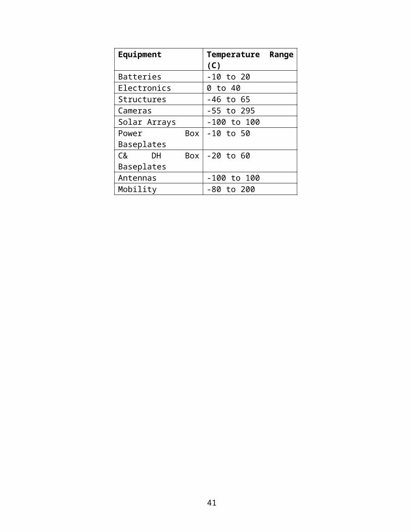
Figure 16: Systems Interacting with Other Systems
The power and thermal subsystems are at the center of the systems interactions as they power and control the life of the overall system. Another important and essential group of subsystems are the communications and the concept of operations subsystems as they are the control center of the system. The guidance, navigation, and control subsystem is the soul of the system as it reads commands from the brain. GN&C is in charge of the whereabouts of the LOW at all times along with guiding the LOW to its destination safely. The mobility subsystem is important as it takes commands from the GN&C subsystem to take the LOW from one destination to another. The structures subsystem is also important as it is the glue that holds the LOW together and protects the LOW from all exterior forces. The payload subsystem is the foundation of the LOW as it is the main reason for the existence of the other subsystems. Therefore, all subsystems are derived for the payload of the mission.
Structure
Mobility
GN&CPayload
Equipment
SRVPower
Thermal
Communications
ConOps
47
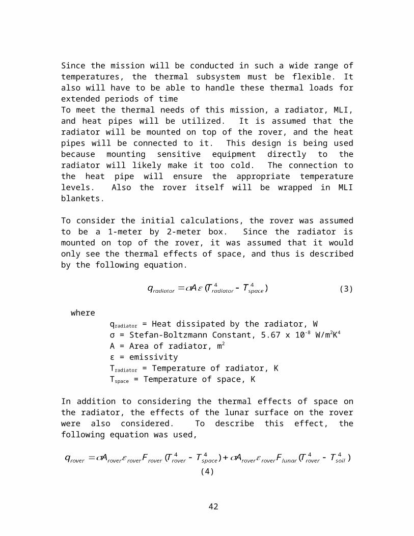
3.0 Implementation Issues
3.1 Schedule
Table 7, below, describes the proposed development schedule for the LOW.
Table 7: Development ScheduleTest Schedule
Year* 1 2 3 4 5Development
N/APrototyping
Guidance, Navigation, & Control Systems
LOW Testing
Digital Imaging Devices Power systems
Guidance, Navigation, & Control Systems
LOW Production
LOW *Years 1 & 5 are 2008 &
2012, respectively.
48
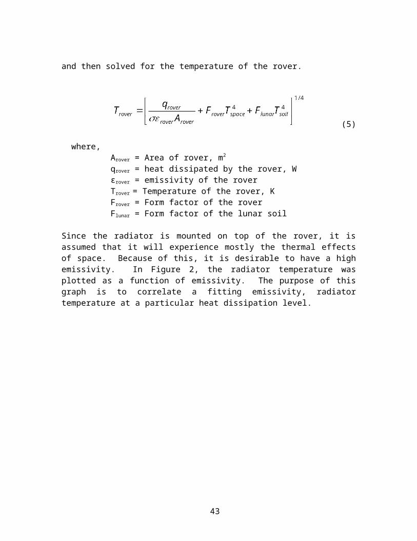
The test schedule above is meant to be a suggested schedule to meet the launch date of NLT 2012 deadline. The first part of this schedule is meant for the development state. One of the most major selling points of the LOW is that it requires no development time as all the technology used on board is rated by NASA as a readiness level 9.
The next two sections of the test schedule are very critical to making the final transition to production as smooth as possible. Prototyping of the systems along with testing will provide the engineers with much more insight into the problems and development needed to overcome these problems. Testing of the systems individually to ensure functionality and collectively to ensure compatibility could reduce future costs and mistakes. A large amount of testing is due to the various targets, goals, and other challenges faced by the LOW.
Finally the production stage listed above is meant to be a congregation of the final production. Therefore, it is only logical to spend an ample amount of time on research and development in order to get a safe and cost efficient final product.
3.2 Hardware DevelopmentThe LOW takes advantage of off the shelf technology in the fact that 100% of the parts on the LOW are tested and in use today.
Team Eclipse placed a lot of importance on the readiness level of certain technologies. All technologies that were used on the LOW were put as a readiness level of 9, which is the readiness level preferred by NASA. Table 8 shows a list of all hardware required on the LOW.
Table 8: List of Hardware on LOW
49
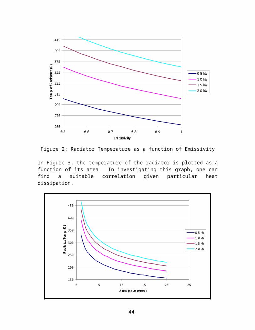
System Hardware HeritageLithium Ion Batteries MERSolar Cells MER, VikingPower Controller VikingPower Cables VikingPanCam, HazCam, NavCam, BellyCam MERIMU Clementine SatelliteStar Tracker Has more than 30 years of Star Tracker
experience built-in, and is manufactured by the company that was first in space with CCD Star Trackers
Radar Altimeter The only altimeter in spaceThrusters/Main Engine ApolloGuidance Computer Deep Impace, XSS-11, Mars
Reconnaissance OrbiterLiDAR XSS-11DSMAC Tomahawk MissileTilt Sensor HuygensReaction Wheels Galaxy Evolution Explorer orbiting space
telescope, Solar Terrestrial Relations Observatory (STEREO)
Sun Sensors CUBESAT picosatelliteRadiators Space ShuttleHeaters ApolloHeat Pipes EndeavorInsulation ApolloCrush Pads VikingExplosive Bolts ApolloRamp Mars PathfinderMobility System MER, Mars PathfinderSRV Materials ProvenCone Pentrometers Apollo, LunokhodExperimental Vane Apollo, LunokhodBearing Plate Apollo, LunokhodGas Spectrometer Huygens, Viking, Mars Polar Lander,
Phoenix, TEGANeutron Spectrometer Lunar Prospector, CRUXMagnets MERXRD / XRF VikingRobotic Drill / Robotic Arm Phoenix, Mars Polar Lander, Viking,
SurveyorHard Drive Space ShuttleS – Band Transmitter Space ShuttleData Cables Space Shuttle
Payload
Communication
Power
Guidance, Navigation, &
Control
Thermal
Structures
4.0 Team Capabilities
4.1 Team Overview
50
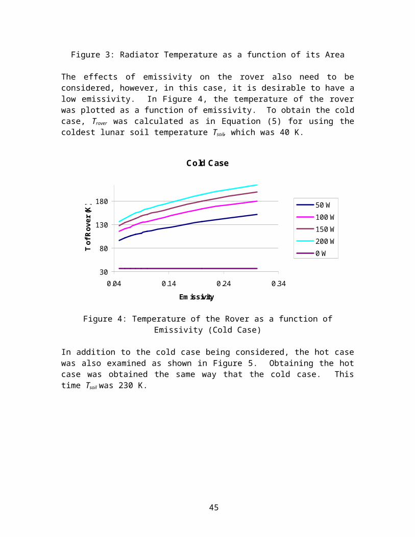
Early on in Phase two, Team Eclipse developed a solid plan for the future development of the LETS. The project manager and Systems Engineer met early on to place each of the UAH team members on a specific subsystem. Once team roles were solidified, the team began weighing the advantages and disadvantages of various design scenarios. Each concept was graded on how well it met the requirements specified in the CDD as well as how many of the FOMs it was able to accomplish. By the end of Phase two, a final concept was selected and Team Eclipse began Phase three of the design process. At the beginning of Phase 3, plans for weekly communication were established with SU and ESTACA.
A Google Group was setup early on to allow all team members to be informed on current design issues or changes to meeting times. The group also gave team members the ability to upload documents of any kind. This feature allowed the Project Office to keep track of a team member’s progression of their subsystem. The Google group also allowed Team Eclipse to meet weekly with ESTACA to discuss updates concerning the SRV, which ESTACA was in charge of designing. The meetings were held in the IPT room using the software Google Talk. A microphone as well as a messenger program allowed everyone in attendance to eliminate any confusion concerning the design or placement of the SRV on the LOW.
Managing team dynamics for Team Eclipse was a tedious task. There were varying personalities on the team that sometimes made it hard to accomplish work. It was the task of the project office to manage the different personalities and keep the team focused on the design of the LOW. Team Eclipse held meetings in a way so that every team member could voice their concerns and not receive verbal attacks from other members of the team. Design changes were made only if a clear majority agreed on the proposed change. Once the team was deep into phase 3, team members began to understand each other and communicate much more effectively resulting in the best possible design for the LOW.
4.2 Personnel Description Eddie Kiessling – Team Eclipse: Project Office
Eddie has been responsible for ensuring the team is staying on task as well as making sure Team Eclipse stays committed to the team goals stated early on during the design process. Being the Project Lead, Eddie is also responsible for ensuring documents are ready to present to the review board on time. He has been instrumental in setting up team meetings with ESTACA through the Google group.
Jay Gala – Team Eclipse: Systems EngineerAs systems engineer, Jay is responsible for the integration of each of the subsystems to ensure that they do not conflict with each other in any way. Jay is very disciplined and often rallies our team back to work when certain team members drift off course. Jay played a major role in both the phase 2 presentation and the design of the open house poster.
Chris Goes- Team Eclipse: Power System Lead
51
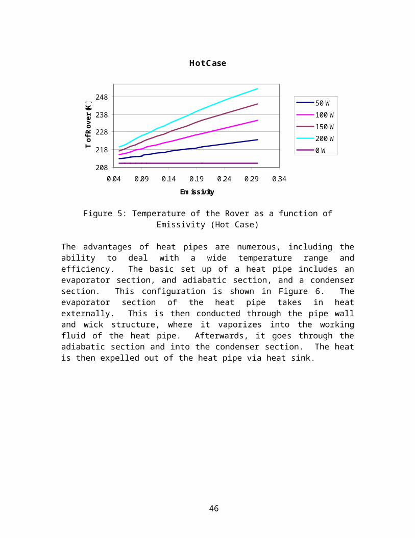
Chris has played huge role in the design. He came through when it was discovered that the RTGs Team Eclipse was relying on for power were no longer a viable source. In a short time, Chris had researched an alternative power source and had begun performing power calculations on the team’s new power source. Chris has also acted for the systems engineer during Jay’s absence to ensure that Team Eclipse continued its forward progress.
Brandon York – Team Eclipse: Guidance, Navigation, and Control LeadBrandon has shifted roles on Team Eclipse quite a few times during the design process. Initially drafted for the power subsystem, Brandon has found his calling as the GN&C lead. Heading GN&C, Brandon is responsible for tracking and navigating the lander for the duration of the mission. Brandon has communicated with his technical mentor regularly learning more and more each day.
Nathan Coffee - Team Eclipse: Structures LeadNathan is in charge of the structures system. As structures lead, he is responsible for designing the landing legs for the LOW, making sure the structure can withstand the landing, and developing an interface with the mobility system being developed by SU. Being the most experienced with CAD, Nathan is called upon frequently to construct various drawings.
Brett Guin – Team Eclipse: Communications LeadAt Team Eclipse’s very first meeting, Brett willing accepted the role of Operations lead, a job no one else was volunteering for. As the Communications lead, Brett has been responsible for constructing a detailed itinerary for our LOW over the course of the entire mission. He has routinely sought the help of his technical mentor during the design process never allowing his subsystem to fall behind.
Kathryn Kirsh – Team Eclipse: Thermal LeadKathryn is the thermal lead for Team Eclipse. Kathryn has been a very reliable member and routinely offers help to other subsystems whenever necessary. Despite being unable to get in touch with her technical mentor early on, Kathryn researched thermal power on her own and continued to meet deadlines given by the project office.
Brent Newson – Team Eclipse: Payload LeadBrent is the Payload lead for Team Eclipse. As the head of payload, Brent is responsible for determining which scientific instruments will be placed on the LOW as well as the exact placement of these instruments on the lander. Brent has worked very closely with Nathan Coffee in order to ensure the mass of the payload is balanced evenly on both sides of the lander.
Joseph Sandlin – Team Eclipse: GN&C
52
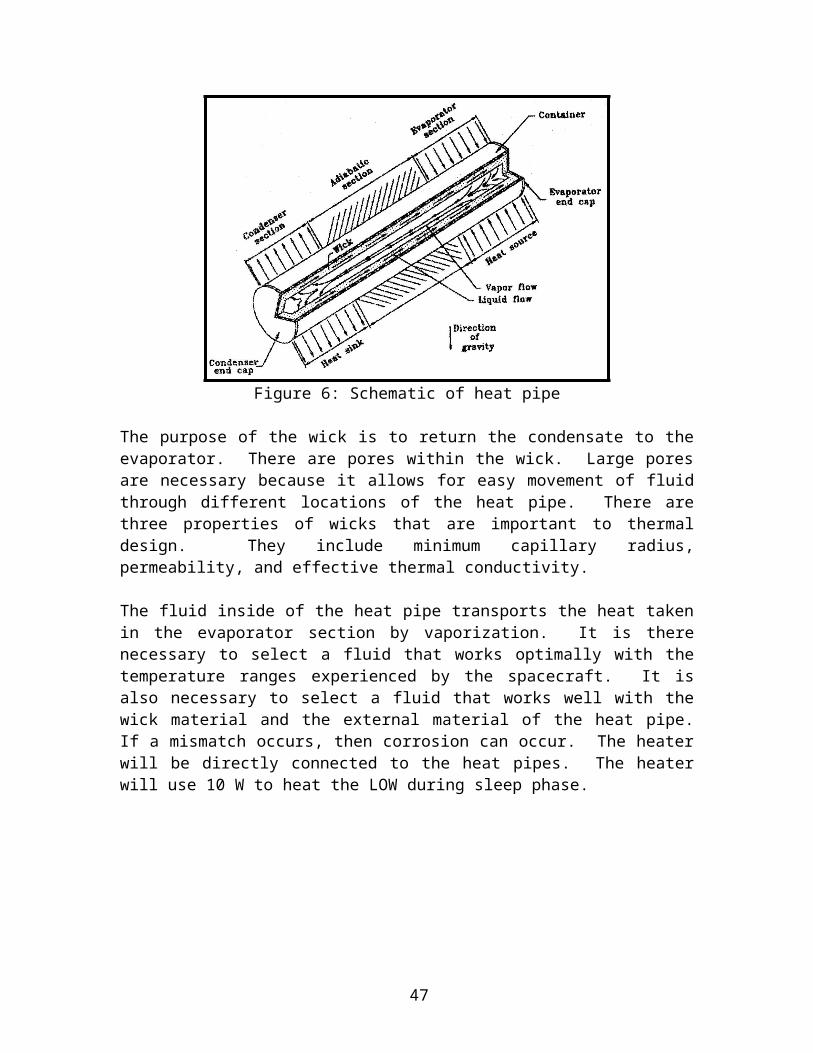
Joseph is an important member of Team Eclipse. He works with Brandon York on GN&C to ensure our LOW is accounted for at all times during the mission. Joseph has been responsible for the selection of cameras for Team Eclipse’s lander. Mr. Sandlin is valuable member of Team Eclipse.
Michael Bryan – Team Eclipse: Technical EditorMichael is the technical editor for Team Eclipse. Mr. Bryan’s main role is to review and edit documents before they go to the review panel. Michael has also been very helpful with the actual design process making several suggestions for the design.
Julien Gobeaut – Team Eclipse: ESTACA, SRVJulien is at ESTACA and responsible for designing the SRV for Team Eclipse’s LOW. Mr. Gobeaut has been very accommodating with the UAH team members by agreeing to meet at UAH’s convenience. Julien has provided several CAD drawings of the SRV throughout the different stages of its construction.
Ghislan Pelieu – Team Eclipse: ESTACA, SRVGhislan is also at ESTACA and works with Julein in designing the SRV. Mr. Pelieu has attended all of the meetings with UAH via Google Talk.
Miles Torregano – Team Ecilpse: SU, MobilityMiles headed the mobility system and was responsible for the design process. He met regularly with the project office to ensure design reliability and functionality. Miles made great contributions in the mobility system for the LOW project with Team Eclipse.
Juan Loretto – Team Eclipse: SU, MobilityJuan was responsible for designing all CAD drawings concerning the mobility system. Juan also assisted Miles to ensure the mobility system was versatile. He worked closely with Nathan Coffee to guarantee that the mobility system conformed to the dimension of the LOW.
Torey Crosby – Team Eclipse: SU MobilityTorey was responsible for exploring possible alternatives to the mobility system during Phase 2 when Team Eclipse was uncertain of the concept of the mobility system.
53
5.0 Summary and Conclusions
5.1 Summary of Design ProcessThe design process of the LOW has progressed through several stages. The initial phase of the design process had the team analyzing the specifics of the Viking Lander and gaining an understanding of the strengths and weaknesses of the Viking Lander design. Once this was accomplished, the team decided on what could be utilized from the Viking Lander and began the search for other alternatives if necessary.
During the second phase of the design process, Team Eclipse analyzed the mobility trade trees from the customer briefing. Using simple logic, the team eliminated several possible alternatives. This process continued until only two mobility concepts remained. At this point, Team Eclipse began looking at how each of these concepts affected various subsystems. Toward the end of phase two, each of the possible mobility concepts were compared and only one concept was chosen to move into phase three. Team Eclipse also established goals during the second phase of the design process. These goals took top priority when selecting technology to utilize on the LOW. Team Eclipse was fully committed to maximizing the scientific payload and reducing the risk of single point failure by employing as much TRL 9 technology as possible. At the end of phase two, Team Eclipse presented their idea to the review board and listened to any concerns the review board had concerning the chosen concept.
At the beginning of phase three, a power and mass budget was established for each of the LOW. Once this was complete, the project office posted the power and mass budget on the team website for all team members to consult during the design of their subsystem. During this time, the systems engineer was working with all subsystems closely to prevent possible conflicts between all the interacting systems. Each team member began compiling a detailed report of their subsystem which would later be submitted to the project office. Once the project office received documentation from every subsystem, the final report was compiled which would be presented to the review board at the culmination of the class.
5.2 Conclusions on Functionality and Science CapabilityBased on the calculations and concept design the LOW will essentially function as a science platform on wheels. The goal of maximizing scientific payload, along with minimizing failure, is at the core of the mission concept. The LOW has several notable capabilities that will allow it to successfully complete its mission while also satisfying the CDD requirements. The rover will be capable of driving an average of 5-6 m/hr while navigating a slope up to 12 degrees. Not only does the LOW fulfill the single site goals with a dedicated science box, but the LOW will be able to travel to all required sites with the option of traveling to more sights as necessary and as allowed by the time constraints. The LOW carries equipment on board which allows it to perform 11 scientific experiments at each site. In addition to this hardware, the LOW carries a communications subsystem that will allow for adequate date transfer rates and ample date storage space. All of these features of the LOW are essential for such a science based mission.
54
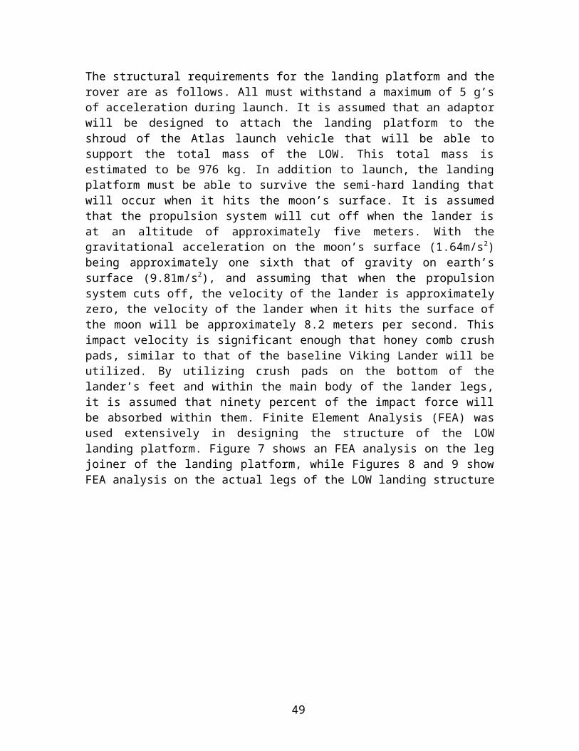
The remaining subsystems of the LOW rover serve to assist in the successful completion of the scientific goals. The power, thermal, structure, and GN&C systems function in such a manner that the LOW is able to meet the CDD requirements with science and safety remaining the top priorities. The LOW will be powered by solar cells and batteries in order to perform the mission tasks in the most efficient and safest manner possible. Thermal insulation and the use of heaters and heat pipes will keep the LOW thermally stable. The structure will be made out of titanium, giving it enough toughness to survive the conditions the LOW will be under. The LOW will be capable of knowing its location and navigating itself throughout the mission. All of these subsystems work together and allow the LOW to achieve the overall mission goals of maximizing scientific payload while minimizing failure potential.
Overall, the LOW concept is a fundamentally sound concept designed specifically for scientific data gathering and successful mission completion. This approach to the LETS project is specific, focused, and useful. The LOW mission has the ability to uncover a great amount of new information regarding the lunar surface.
6.0 RecommendationsPower was a major concern in the designing of the LOW. The major constraint was the lack of new technology and lack of materials for old technology. An RTG would be able to provide more than enough electrical and thermal power needed for the mission, but due to the lack of Plutonium-238, the idea of putting RTGs on the LOW was ruled out. The lack of new technology has also created problems for the LOW, as late in Phase 3 of the design process, fuel cells (due to electrolysis) were not considered to be a valid power source.
Thermal was another major concern in the designing of the LOW. Again, the lack of materials for old technology made it difficult to create a thermal system which would function properly in extreme temperature ranges such as 50K to 400K.
Cost is another major issue with this project. One way to help reduce costs is to find new materials which have the same strength and durability as the materials needed but at a lower cost.
55

Appendices
Appendix A - Concept Description Document
Concept Description Document Approval:
The undersigned agree that the attached Concept Description Document as marked will be the basis the UAH IPT 2008 Design Competition. From this time forward, any questions or clarifications concerning the concept description document to the Customer shall be submitted in writing and the answer distributed to all UAH IPT’s in writing.
To change the Concept Description Document Prior to May 2, 2008 shall require that the change be stated in writing and that a person authorized by every one of the signers below endorse the change with their signature. The revision will be labeled uniquely and distributed to all teams simultaneously.
The original of this document will be kept on file with the UAH Project Director. All signers will receive a copy of the original document.
__________________/__________Nick Case, UAH IPT Team D, Project Office
__________________/__________Eddie Kiessling, UAH IPT Team E, Project Office
__________________/__________Matt Isbell, UAH IPT Team E, Project Office
__________________/__________David Jacobson, UAH IPT Project Customer
__________________/__________Michael P.J. Benfield, UAH IPT Project Leader (Class Instructor)
__________________/__________Robert A Frederick, UAH IPT Project Director
1
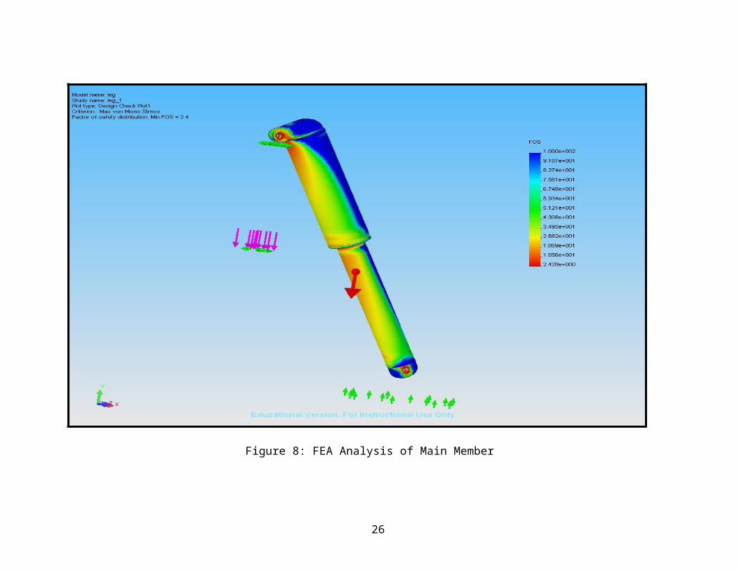
1. Scope. This document outlines the specifications for the Lunar Exploration Transportation System (LETS). The LETS project is to develop a lunar lander mission for NASA that provides the flexibility to conduct different scientific investigations and technology validation tasks at different areas on the moon’s surface. For this study only one lander is envisioned. The mobility of the lander system is subject to trade. For the purposes of this project, the mission begins with terminal descent. The project goal is to design the transportation system to accomplish the scientific and technology objectives, not the science and technology itself.
2. Customer Requirements. The following requirements were given by the customer as Level 1 Requirements.
2.1. The LETS shall use an Atlas V-401 EPF shroud configuration with a total landed mass of 997.4 kg.
2.1.1. The LETS shall be designed so that 64.6 kg of the total landed mass is devoted to the propulsion system dry mass. Table 1 details this mass allocation to the propulsion subsystems.
2.1.2. The LETS propulsion system shall be designed to accommodate 159.5 kg of hydrazine (N2H4) propellant and 2.0 kg of helium. The propellant shall be housed in two spherical propellant tanks, each 0.55 m in diameter. The helium shall be housed in 2 spherical tanks, each 0.4 m in diameter.
2.1.3. The LETS propulsion system shall be designed for two (2) MR-80B monopropellant liquid rocket engines.
2.1.4. The LETS attitude control system shall be designed for twelve (12) MR-106 monopropellant thrusters.
2.2. The LETS shall be designed for its first mission to be at a polar location.2.3. The LETS shall be designed with the capability to land at other lunar locations.2.4. The LETS shall minimize cost across the design.2.5. The LETS shall launch to the moon NLT September 30, 2012.2.6. The LETS shall have the capability to move on the surface.2.7. The LETS shall be designed to survive for one year on the surface of the moon.2.8. The LETS shall survive the proposed concept of operations.2.9. The LETS shall be capable of meeting both the Science Mission Directorate
(SMD) and the Exploration Systems Mission Directorate (ESMD) objectives.2.10. The LETS shall land to a precision of ± 100m 3 sigma of the predicted
location.2.10.1. The LETS shall provided guidance, navigation, and control for the
terminal descent phase, beginning at 5 km above the surface of the moon.
2.10.2. The LETS shall not be responsible for hazard avoidance.2.11. The LETS shall be capable of landing at a slope of 12 degrees (slope between
highest elevated leg of landing gear and lowest elevated leg).
2
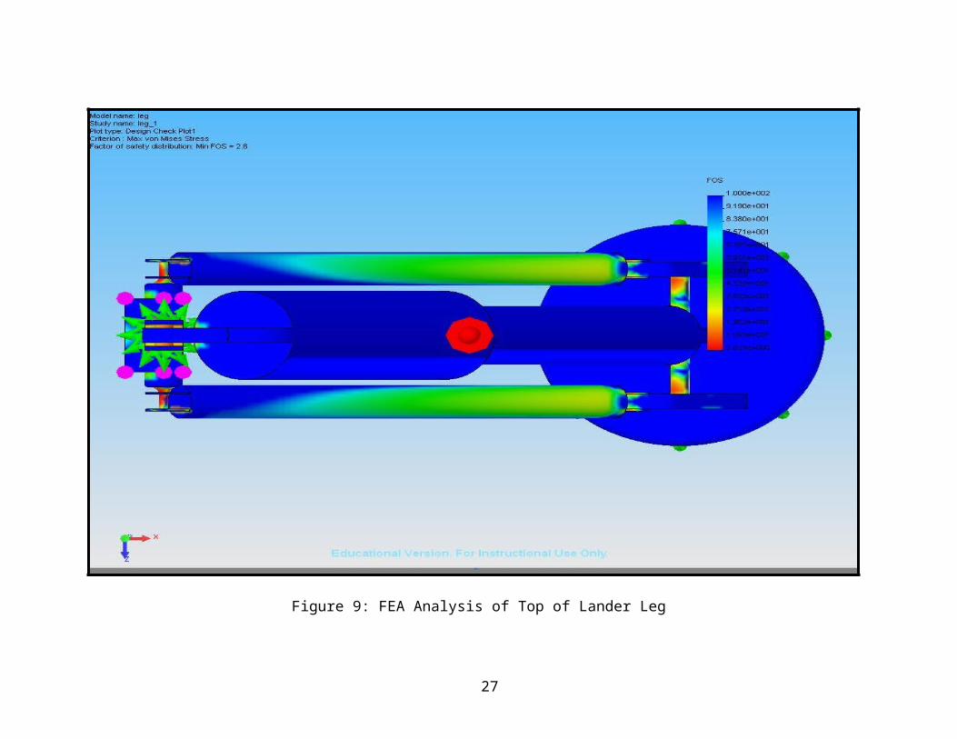
2.12. The LETS shall be designed for g-loads during lunar landing not to exceed the worst case design loads for any other phase of the mission (launch to terminal descent).2.12.1. The LETS shall be designed to withstand g-loads with respect to
stiffness only.2.12.2. The LETS design shall not be concerned with frequency responses
or frequency loads.
3. Concept Design Constraints. The following constraints are placed on the LETS design.
3.1. The LETS shall be designed to interface with the Atlas V-401 EPF shroud configuration launch vehicle per the Atlas Launch System Mission Planner's Guide, Rev 10a, January 2007, CLSB-0409-1109.
3.2. The LETS shall be designed to survive the lunar cruise environment for up to 28 days per NASA Technical Memorandum 82478, Space and Planetary Environment Criteria Guidelines for Use in Space Vehicle Development, Volume 1. Including but not limited to the following environment obstacles3.2.1. Radiation3.2.2. Thermal3.2.3. Micrometeoroids
3.3. The LETS shall be designed to survive the lunar surface environment at both the polar and equatorial regions.3.3.1. This includes temperatures ranging from 107 Celsius to -223
Celsius3.3.2. Including conditions stated in section 3.2
3.4. The LETS shall maximize the use of off-the-shelf technology. Off-the-shelf technology shall have a technology readiness level of 9.3.4.1. Readiness of level 9 states it is an actual “Flight Proven” system
through successful mission operations.3.5. The LETS shall be designed to accomplish the maximum surface objectives
outlined below.
4. Figures of Merit. The following Figures of Merit (FOM) will be used to evaluate the LETS design concepts.
4.1. Number of surface objectives accomplished (as outlined below)4.2. Percentage of mass allocated to payload4.3. Ratio of objectives (SMD to ESMD) validation (2 to 1 being the goal)4.4. Efficiency of getting data in stakeholders hands vs. capability of mission4.5. Percentage of mass allocated to power system4.6. Ratio of off-the-shelf hardware to new development hardware
5. Surface Objectives. The following surface objectives were provided by the customer.
5.1. Single site goals - Geologic context
3
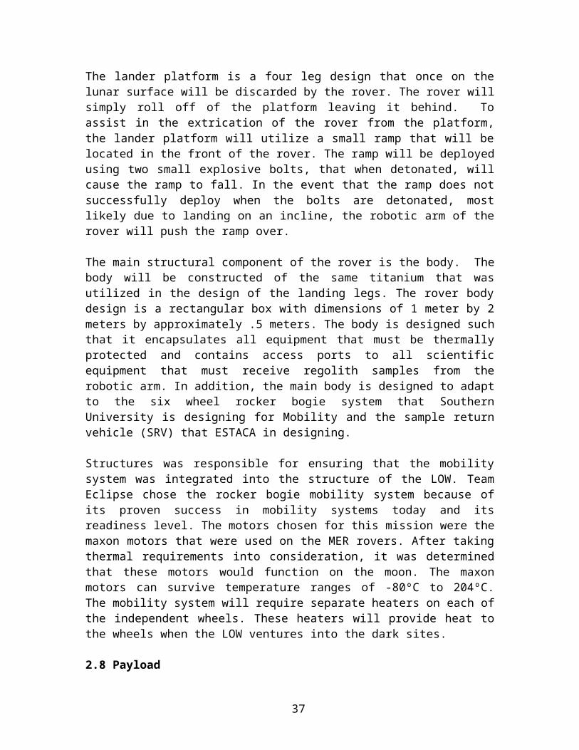
5.1.1. Determine lighting conditions every 2 hours over the course of one year
5.1.2. Determine micrometeorite flux5.1.3. Assess electrostatic dust levitation and its correlation with lighting
conditions5.2. Mobility goals
5.2.1. Independent measurement of 15 samples in permanent dark and 5 samples in lighted terrain
5.2.2. Each sampling site must be separated by at least 500 m from every other site
5.2.3. Minimum: determine the composition, geotechnical properties and volatile content of the regolith
5.2.4. Value added: collect geologic context information for all or selected sites
5.2.5. Value added: determine the vertical variation in volatile content at one or more sites
5.2.6. Assume each sample site takes 1 earth day to acquire minimal data and generates 300 MB of data
5.3. Instrument package baselines5.3.1. Minimal volatile composition and geotechnical properties
package, suitable for a penetrometer, surface-only, or down-bore package: 3 kg
5.3.2. Enhanced volatile species and elemental composition (e.g. GC-MS): add 5 kg
5.3.3. Enhanced geologic characterization (multispectral imager + remote sensing instrument such as Mini-TES or Raman): add 5 kg
Table 1. Propulsion Dry Subsystem MassSubsystem Number Mass/Unit (kg) Total Mass (kg)
Propellant Tank 2 5.1 10.2Helium Tank 2 5.2 10.4
Helium 2 1.0 2.0Main Engine 2 7.9 15.8ACS Thruster 12 0.5 6.0Components 1 14.1 14.1Contingency 1 6.1 6.1
4
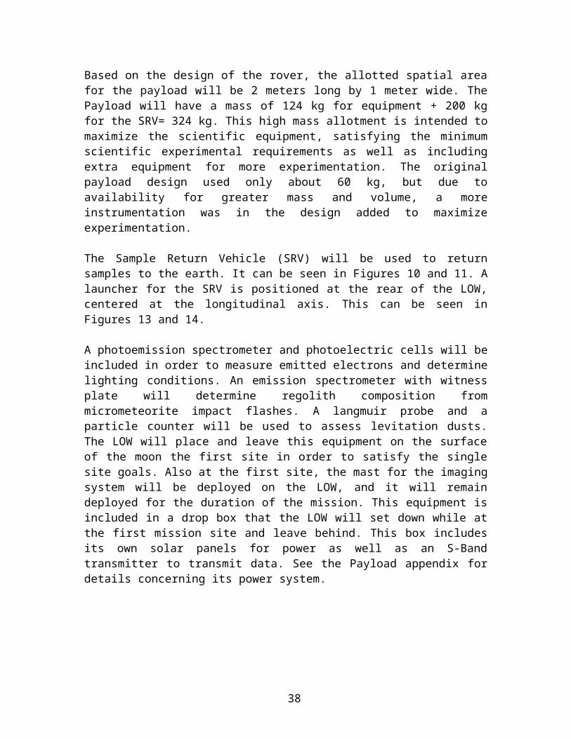
Appendix B – Power
Solar Cells Calculations
5
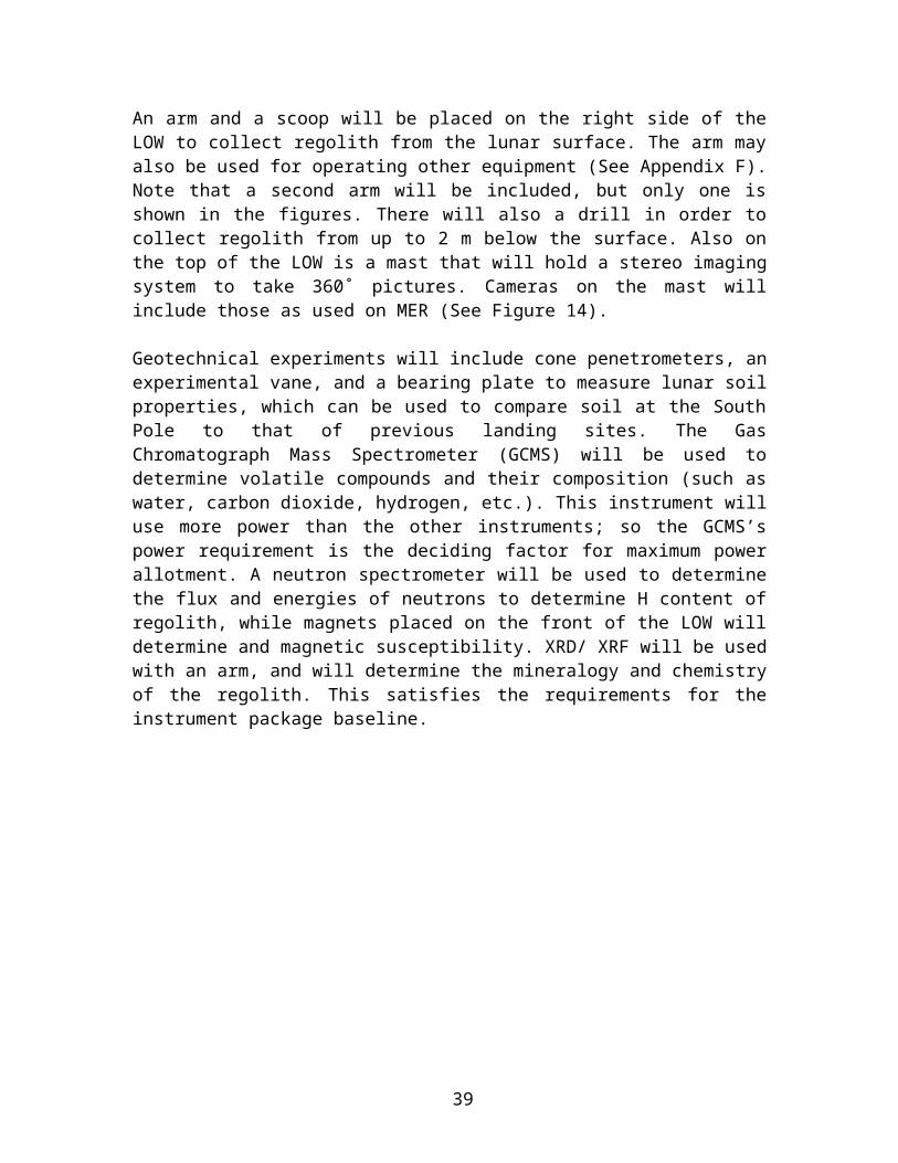
Battery Calculations
6
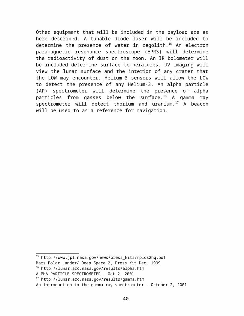
Appendix C - Guidance, Navigation, and ControlGN&C Specification Sheet
Instrument Type Vendor Model Qty. Dimensions (mm) Mass (kg) Power Consumption (W) Temperature Range MTBFInertial Measurement Unit ACS Sensor Northrop Grumman LN-200 Fiber Optic 2 88.9 Dia x 85.1 H 1.5 12 (-54°C to 71°C) >20,000 hrsStar Tracker ACS Sensor Goodrich HD-1003 1 135 Dia x 142 H 3.4 10 (-30°C to 65°C) 1M hrsSun Sensor ACS Sensor Optical Energy Technology Model 0.5 2 20 Dia x 40 H 0.008 0.05 (-30°C to 80°C) 131,400 hrsRadar Altimeter ACS Sensor Honeywell HG8500 1 86.4 W x 86.4 H x 142.4 L 1.36 16 N/A 5000 hrsTilt Sensor ACS Sensor Seika NG3 Inclinometer 2 67 Dia x 21.6 H 0.22 0.005 (-40°C to 85°C) N/AReaction Wheel ACS Actuator Ithaco Type A 1 204 Dia x 63.5 H 5.9 7 N/A 2M hrsMain Engine ACS Actuator Aerojet MR-80B 2 N/A 15.8 N/A N/A N/AThrusters ACS Actuator Aerojet MR-106 12 N/A 5.712 27 N/A N/AGuidance Computer Computer BAE Systems RAD750 2 130 sq mm (micoprocessor) 0.009 5 (-55°C to 125°C) >4.3M hrsLiDAR Optical MDA-Optech N/A 1 533.4 x 533.4 x 533.4 1.25 N/A N/A N/ADSMAC Optical Raytheon IIA 1 N/A N/A N/A N/A
Optical N/A Navcam 167 x 69 x 34 (electronics)41 x 51 x 15 (detector head) 0.22 2.15
N/A N/A
Optical N/A Hazcam 467 x 69 x 34 (electronics)41 x 51 x 15 (detector head) 0.98 2.15
N/A N/A
Optical N/A Pancam 267 x 69 x 34 (electronics)41 x 51 x 15 (detector head) 0.54 2.15 N/A N/A
Optical N/A Belly Cam 1 N/A 0.265 N/A N/A N/A
Cameras
7
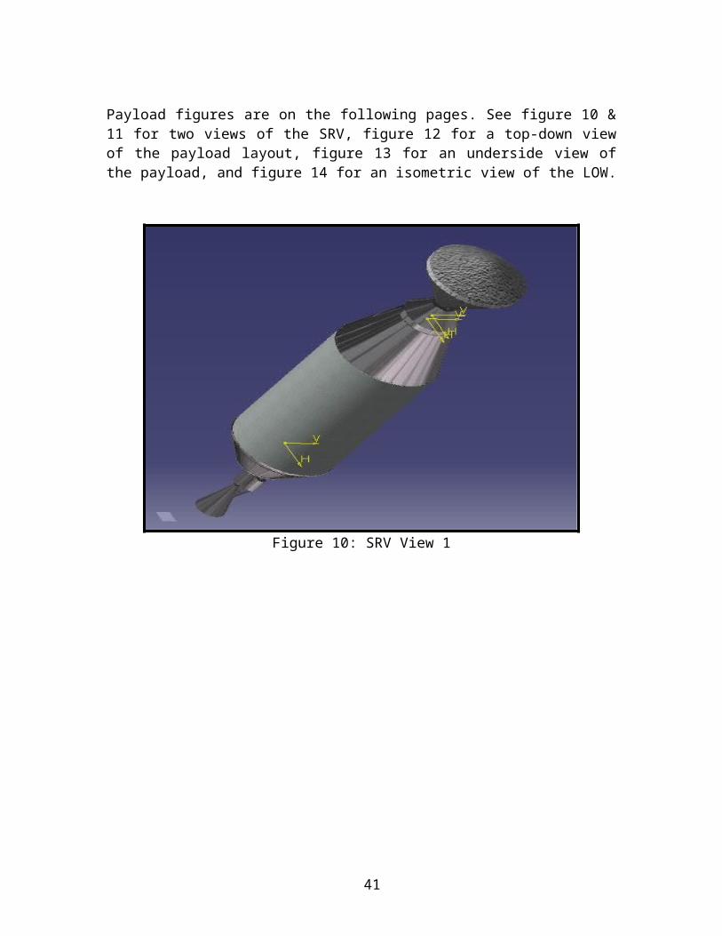
Redundancy Control Flowchart
Explanation:TDP Redundancy – A secondary IMU backs up the primary IMU. The Star Tracker and sun sensors back up/supplement the IMU. LiDAR Supplements the DSMAC system. The radar altimeter supplements the DSMAC system and backs up the LiDAR system. Reaction wheels back up the ACS Thrusters/Main Engine. LEP Redundancy - Tilt sensors supplement the IMU and the cameras back up the IMU
Appendix D – Thermal
8
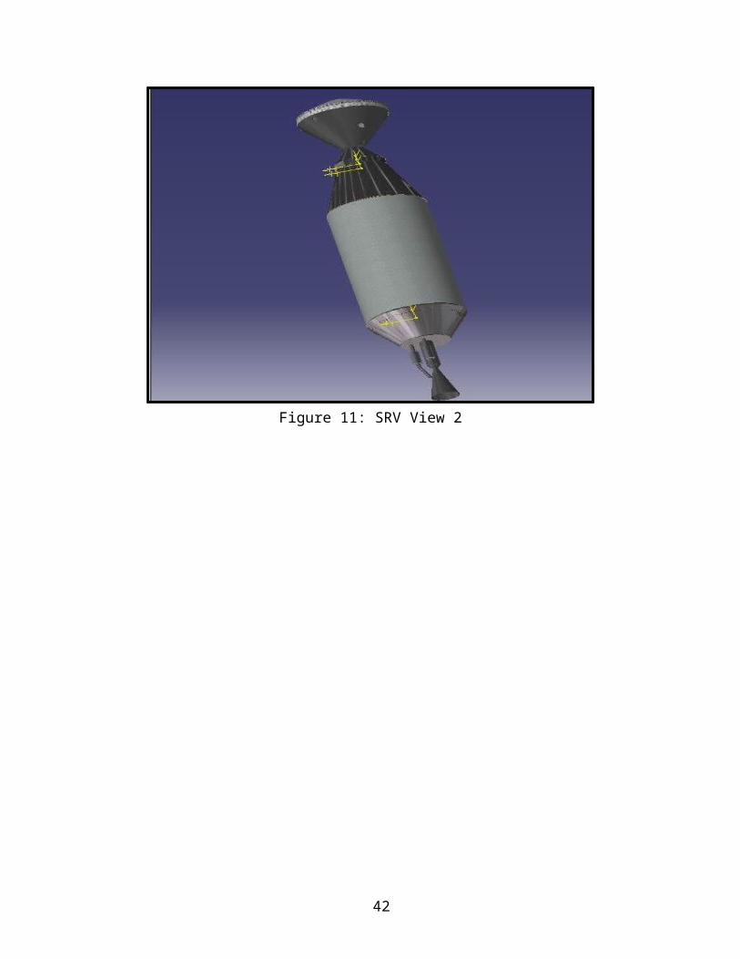
The Heat dissipated by the Radiator
qradiator 500W
5.6710 8W
m2 K4
A 15 m2
0.5
Tspace 0 K
Tradiatorqradiator A
Tspace4
1
4
Tradiator 185.175K
Temperature of the Rover, Cold Case
qrover 50W
rover 0.05
Frover 0.3
Flunar 0.7
Tsoil1 40K
Trovercqrover
A roverFrover Tspace
4 Flunar Tsoil14
1
4
Troverc 185.245K
9
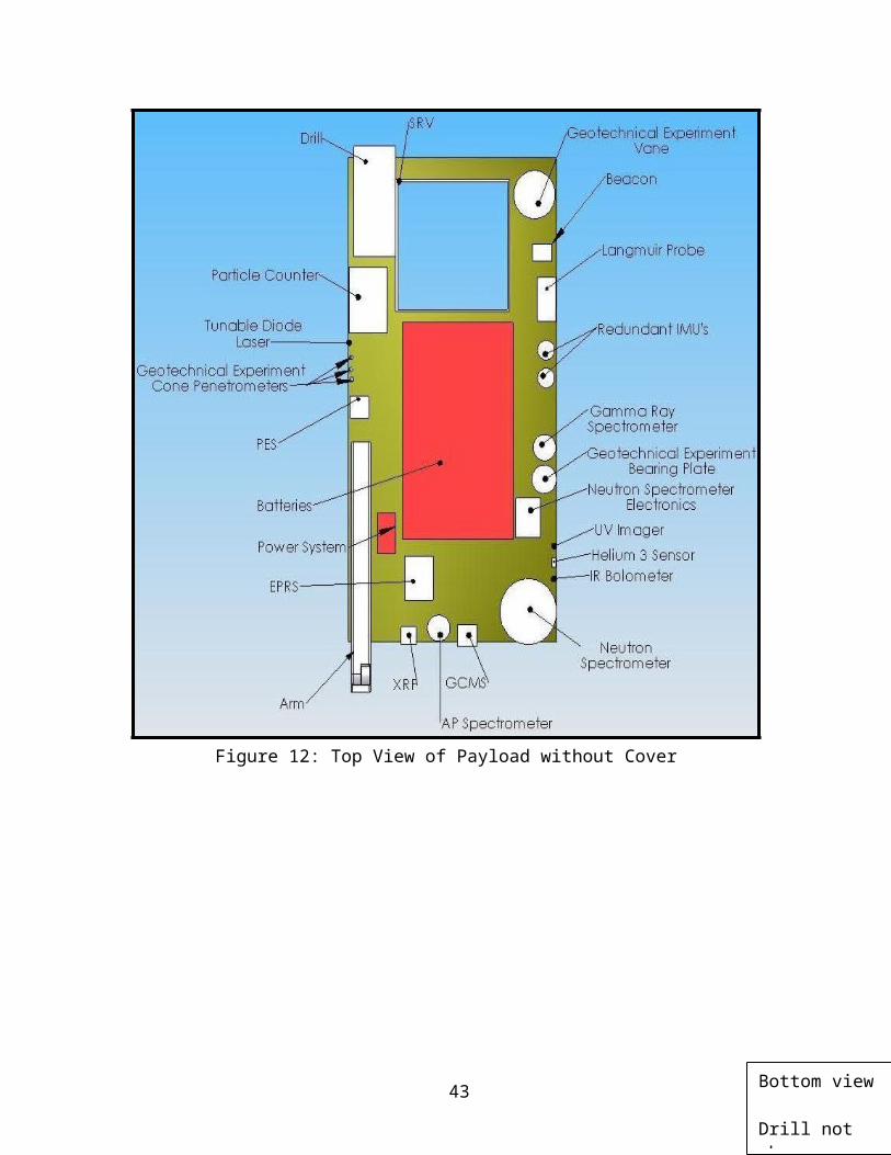
10
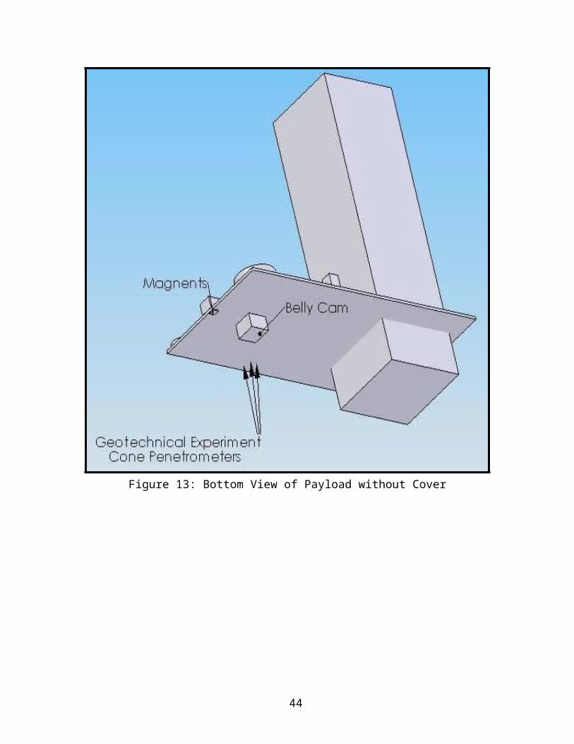
Temperature of the Rover, Cold Case
Tsoil2 230K
Troverhqrover
A roverFrover Tspace
4 Flunar Tsoil24
1
4
Troverh 236.618K
11
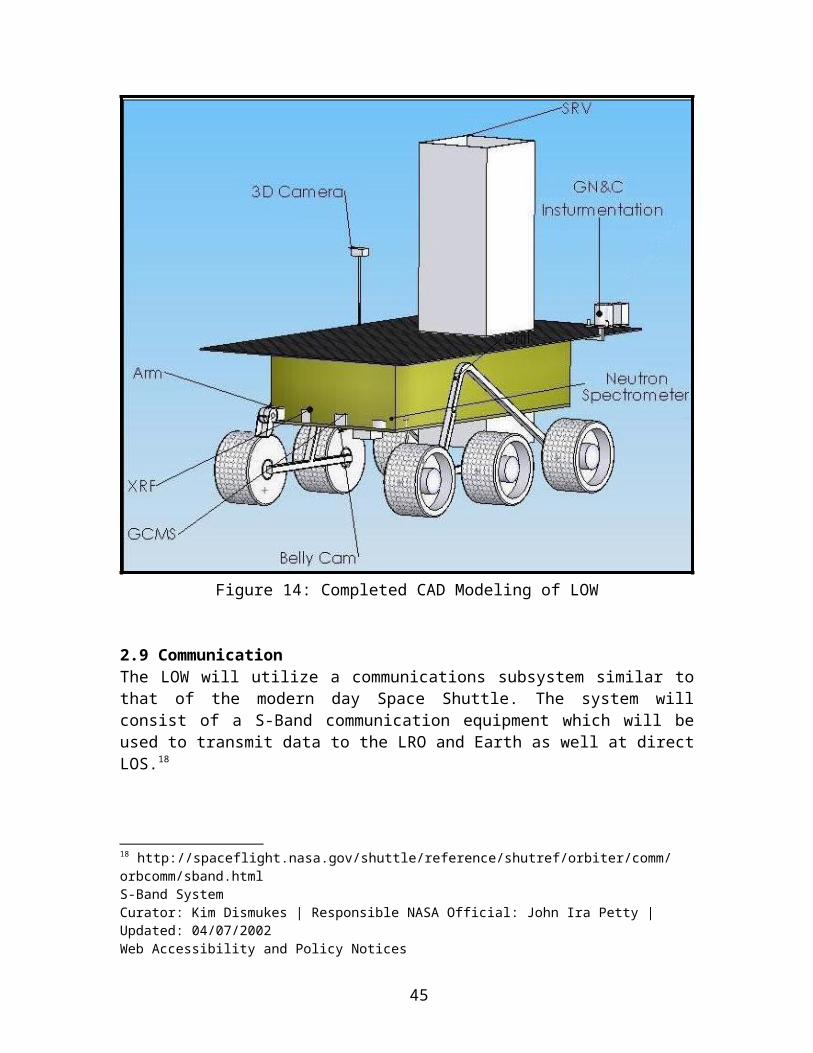
From COSMOS FEA analysis of the leg assembly, the minimum Factor of safety is 1.5. To verify the accuracy of this analysis, the manual method for calculating the max stress is performed.
Titanium Material Properties
Sy 1.4 108N
m2
Forces on member
Mlander 970kg
Impact 2 due to the assumption the crush pads will absorb 90% of the impact force.
I 2
The lander is a four leg configuration so:
FlegFtotal
4
FpinFleg
2
Since there are two pins, the force isdivided between each.
Fpin 400.125N
12
Su 2.35108N
m2 E 1.1 1011
N
m2
g 1.65m
s2 Force Mlander g Force 1.601 103 N
Ftotal Force I Ftotal 3.201 103 N
Fleg 800.25N
As a simplified assumption, the forceacting on the pin is in the middle of it.
Dist3.62
cmDpin 1cm r 0.5cm
M Fpin DistM 7.202m2 N
m
nom32 M
Dpin3
nom 7.336 107N
m2
13
From "Fundamentals of Machine Design" Stress concentration factorsDpin 1cm Dbase 4cm r 0.5cm
rDpin
0.5DbaseDpin
4 From Fig. 4.35 Kt 1
Since Kt is approximately 1 stress concentration is an insignificant factor.
max nom
For Shear Stress
A Dpin
2
4 A 0.785cm2
max43
FpinA
max 6.793 106N
m2
Von Mises Stress Analysis
e max2
3 max2
1
2 e 7.43 107
N
m2
FSSye
FS 1.884
The small difference in the factor of safety is most likely due to the assumption that the force is applied directly to the center of the pin.
max 7.336 107N
m2
14
15
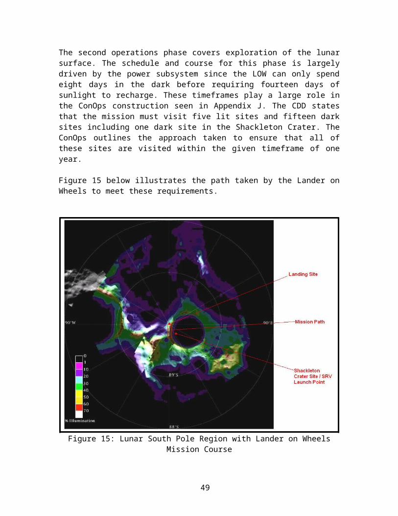
16
Appendix F - Payload
Lander Payload Element Objective Mass (kg)
Power (W)
Order of Operations Notes Heritage
The following items are used upon landing.
Mast for stereo imaging system Provide elevation and pointing for imaging 3.5 9.5 Single
deployment
Mast deployed upon landing. Holds stereo imaging system (cameras, etc.)
MER, Pathfinder
Photoemission Spectroscopy (PES)
Measures electrons emitted from solids, gases or liquids by the photoelectric effect, in order to determine the binding energies of electrons
3 ContinuousDeployed upon landing. Single-site goal.
Photoelectric Cells Determines Lighting Conditions 1 Continuous
Deployed upon landing. Single-site goal.
Emission spectroscopyDetermine chemical composition from micrometeorite impact flashes
3.0 7.0 ContinuousDeployed upon landing. Single-site goal.
Witness plate Target to observe micrometeorite impacts 1 Continuous
Deployed upon landing. Single-site goal.
Langmuir probe Levitated dust 3.0 5.0 ContinuousDeployed upon landing. Single-site goal.
Ground based and flight
Particle counter Levitated dust 7.0 7.5 ContinuousDeployed upon landing. Single-site goal.
Ground based and flight
17
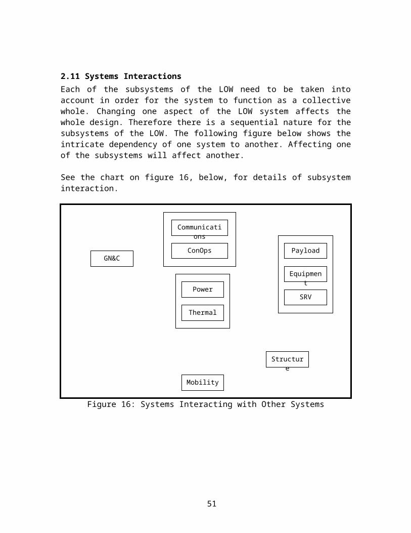
Neutron Spectrometer
Determine the flux and energies of neutrons to determine H content of regolith
1.0 1.8 Single measurement
Assumes Los Alamos HYDRA design. Sensitivity to 0.5 wt% H2O under 50 cm dry regolith. Can be mounted on the vehicle.
Lunar Prospector, CRUX
The following items are used as needed.
ArmDeploy instruments, conduct geotechnical experiments, collect regolith samples
13.0 43.0 Multiple uses
Used in conjuction with scoop and geotechnical experiments.
Phoenix, Mars Polar Lander, Viking, Surveyor
ArmDeploy instruments, conduct geotechnical experiments, collect regolith samples
13.0 43.0 Multiple uses
Used in conjuction with Gamma Ray Spectrometer, XRD/XRF.
Phoenix, Mars Polar Lander, Viking, Surveyor
Beacon Navigation reference 1.0 5.0Activates
when threatened
The following items are in order as given.
Drill and drill deployment mechanism Recover regolith samples from depths of up to 2 m 20.0 30.0 1
Apollo, Phoenix, Honeybee and Swales development activities
Belly Cam Imaging of drill interface with surface 0.4 3.8 1 Used with drill as
needed
Scoop Recover surface regolith samples 0.5 0.0 1 Deployed with arm Surveyor, Phoenix, Viking
GCMS (Gas Chromatograph Mass Spectrometer)
Determine the volatile compounds present and their isotopic composition
19.0 75.0 2 Runs for 4 hours.
Huygens, Viking, Mars Polar Lander, Phoenix, TEGA, SAM experiment MSL
18
GCMS Sample processing system Process core or scoop material for analysis for GSMS 1.0 2
Use to prepare regolith samples with GCMS.
Mars Science Laboratory, Viking, RESOLVE
Tuneable Diode Laser Determine the amount of H2O present in the regolith, in situ 1.0 10.0 3 Mars Polar Lander, SAM -
MSL,
XRD / XRF Mineralogy and chemistry of regolith 2 10 3 Deploy with arm.
EPRS (Electron paramagnetic resonance spectroscopy)
Determine the reactivity of the dust for biologic implications 5.0 5.0 4
EPRS Sample processingSeparate regolith particles into >100 nm and <100 nm size fractions
1.0 4
Geotechnical Experiments - bearing plate End effector for geotech properties 1.0 0.0 5 Deployed with arm. Apollo, Lunokhod
Geotechnical Experiments - cone penetrometer (3)
End effector for geotech properties 1.5 0.0 5 Deployed with arm. Apollo, Lunokhod
Geotechnical Experiments - shear vane End effector for geotech properties 0.5 0.0 5 Deployed with arm. Apollo, Lunokhod
MagnetsDetermine magnetic susceptibility of regolith particles
0.5 0.0 6 Mounted on front of rover MER
IR Bolometer Determine surface and near surface temperatures 2.0 5.0 6
Guess. Power estimate based on imaging system detectors.
UV imaging View the interior of the crater with Lyman a illumination 5.0 5.0 6 Alan Stern email. LAMP
mass 5 kg.
19
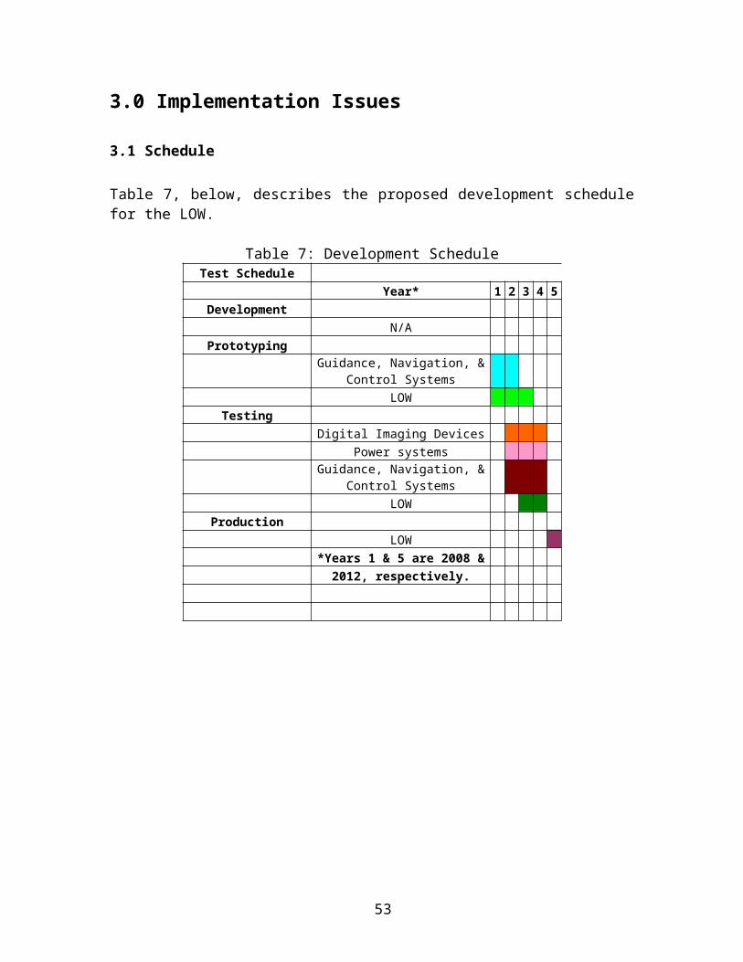
Helium-3 Sensors Detect presensce of He-3, can be used for power 1.0 7
Alpha Particle SpectrometerDetects A.P.s emitted by radioactive gases leaking from lunar interior
4.0 7.0 7 Lunar Prospecter
Gamma Ray Spectrometer Detects presense of thorium and uranium. Uses arm. 8.6 7 Lunar Prospecter
Stereo imaging system Acquire images of surface for analysis 0.8 6.0 8
360° stereo images. Uses MER cameras as described elsewhere.
MER, MSL
Illumination for stereo imaging system Provide illumination for dark imaging 0.4 1.0 8 Used when needed.
Total mass / Power (Not all equipment used at one time - power constraints not an issue)
123.5 265.6
20
Solar Calculations
Xe .65 Pe 1W Pd 5W Te 14day Td 14day Xd .85
Prv
Pe Te
Xe
Pd Td
Xd
Td degration 3.75% Lsa 1yr
23.5deg P0 302W
m2 Id .77 LD t( ) 1 degration( )
t
yr
Ld LD Lsa PBOL P0 Id cos
PEOL PBOL Ld
ArvPrv
PEOL Arv 0.036m2
mSC .04kgW
Prv mSC 0.297kg
DOD .65 nrv .9 Nrv 1
Pn 1W Tn 14day
CrPn Tn
DOD Nrv nrv Cr 574.359W hr
densityLiIon 70W hr
kg
mBCr
densityLiIon mB 8.205kg
mC 5kg
mI 7.5kg all instrumentation including light sensors, micromeatorite flux sensors, andelectrostatic dust levetation sensors for all single sight goals
MT mSC mB mC mI MT 21.002kg
21
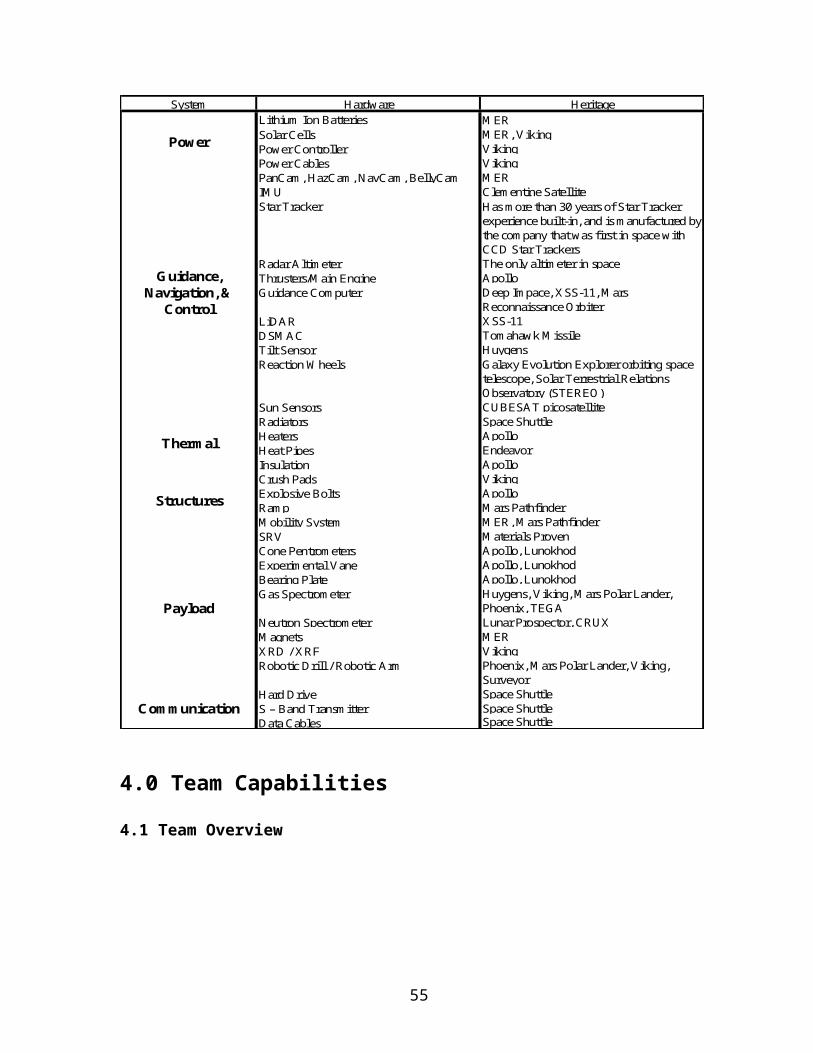
Appendix G – SRVGeneral presentation
Each physical system has got a proper behaviour. So the probability that its behaviour corresponds to the behaviour we would like to obtain is very low: that’s why we have to control it with different methods.We have three major steps:
Navigation: it gives the position and the speed of the vehicle thanks to an inertial unit, which can work in parallel with a GPS unit.
Guidance : it computes during the flight the control rules that will be used on the vehicle systems :
o Entries: information from the navigation, orbits information, characteristics of the rocket.
o Command: attitude orders to the systems of control (orientation of the thrust).
Control: it must follows the orders coming from the guidance block; ensure the stability of the rocket.
o Entries: attitude measures given by the inertial unit, orders from the guidance.
o Command: orders for the orientation of the nozzles.
The drawing here shows the interactions between navigation, guidance and control.
Choice of the type of control for the SRV
To command our SRV during its propulsion phase, we have several different solutions:
Reaction control system thanks to thrusters, 30 N class Control by orientation of the nozzle thanks to hydraulic actuators
1. Orientation of the nozzle
During all our studies on the SRV control systems, we will base on the Ariane-5 systems. It means that we will use the same type of sensors and actuators of that rocket.
Sensors:
We have several different sensors on our SRV: 2 RLG (Ring Laser Gyros) giving:
o Acceleration measures (accelerometers)o Attitude measures (thanks to the integration of gyros’ measures)
2 gyros giving the angular speed
22
Pressure, airspeed, angle of attack: used for the re-entry capsule
Control actuators:
Thrust orientation by hydraulic or electric servo-actuators, in propulsion phase. Opening control of nozzles during ballistic phase: cold gas, hydrazine Orientation of aerodynamic actuators during re-entry phase
We will now focus on the control of the Thrust Vectoring Control (TVC) chain for mobile nozzles.To orientate the propelling thrust:
The nozzle is being orientated by the SVG, that receives orders from the calculator
The SVG has got 2 actuators situated in 2 orthogonal plans. Each actuator is placed between a fixed point from the structure (‘A’) and a
mobile point on the nozzle (‘T’). By making a variation of its elongation, each actuator implies a rotation of the
nozzle in its activation plan.
Control system study
In this part, we will present a control system study of the rocket. Indeed, we will control the attitude in yaw and pitch of the rocket.
The description below shows the relation between pitch, yaw angle and angle of rotation of the nozzle.
Two actuators are going to make the rocket rotate in pitch and yaw. They’ll be disposed like that:
23
The description below shows the principle of the nozzle orientation, made by a linear actuator.
Pitch actuator
Nozzle
Pitch actuator
Nozzle
Contributors
Project OfficeEddie
KiesslingSystems
EngineeringJay GalaGuidance Navigation &
ControlBrandon York / Joseph
SandlinPowerChris
GoesThermal Kathryn
KirshOperations/Communicati
onsBrett GuinPayloadBr
ent NewsonStructur
esNathan CoffeeTechnical EditorMichael
Bryan
Sample Return VehicleJulien
Gobeaut Sample Return VehicleGhislan
PelieuMobilityMiles
TorrengoMobilityTorey
CrosbyMobilityJuan Loretto
Contributors
Project OfficeEddie
KiesslingSystems EngineeringJay GalaGuidance Navigation &
ControlBrandon
York / Joseph SandlinPowerChris
GoesThermal
Kathryn
KirshOperations/CommunicationsBrett
GuinPayloadBrent NewsonStructuresNathan CoffeeTechnical Editor
Michael Bryan
Sampl
e Return VehicleJulien Gobeaut Sa
mple
Return VehicleGhislan PelieuMobilityMiles TorrengoMobilityTorey CrosbyMobilityJuan Loretto
Contributors
Project OfficeEddie KiesslingSystems EngineeringJay
GalaGuidance Navigation & ControlBrandon York /
Joseph SandlinPowerChris
GoesThermal Kathryn KirshOperations/Commun
icationsBrett GuinPayloadBrent
NewsonStructuresNathan CoffeeTechnical
EditorMichael Bryan
Sample Return VehicleJulien Gobeaut
Sample Return VehicleGhislan Pelieu
MobilityMiles TorrengoMobilityTorey
CrosbyMobilityJuan Loretto
Contributors
Project OfficeEddie KiesslingSystems EngineeringJay GalaGuidance Navigation &
ControlBrandon York / Joseph
SandlinPowerChris GoesThermal
Kathryn KirshOperations/CommunicationsBrett GuinPayloadBrent
NewsonStructuresNathan CoffeeTechnical EditorMichael Bryan
Sample Return VehicleJulien
Gobeaut Sample Return
VehicleGhislan Pelieu
MobilityMiles TorrengoMobilityTor
ey CrosbyMobilityJuan
Loretto
Contributors
Project OfficeEddie
KiesslingSystems EngineeringJay
GalaGuidance Navigation &
ControlBrandon York / Joseph
SandlinPowerChris GoesThermal
Kathryn KirshOperations/Communications
Brett GuinPayloadBre
nt NewsonStructure
sNathan CoffeeTechnical EditorMichael
Bryan
Sample Return VehicleJulien
Gobeaut Sample Return
VehicleGhislan Pelieu
MobilityMiles TorrengoMobilit
yTorey CrosbyMobilityJ
uan Loretto
Contributors
Project OfficeEd
die KiesslingSystems EngineeringJay
GalaGuidance
Navigation &
ControlBrandon York / Joseph
SandlinPowerChri
s GoesThe
rmal Kathryn KirshOperations/CommunicationsB
rett GuinPayloadBrent NewsonStructuresNathan CoffeeTechnical
EditorMichael Bryan
Sample Return
VehicleJulien
Gobeaut Sample Return
VehicleGhislan Pelieu
MobilityMiles
TorrengoMobility
Torey CrosbyMobilityJu
an Loretto
Contributors
Project OfficeEd
die KiesslingSystems
EngineeringJay
GalaGuidance
Navigation &
ControlBrandon York / Joseph
SandlinPowerChri
s GoesTher
mal Kathryn
KirshOperations/CommunicationsBre
tt GuinPayloadBrent NewsonStructuresNathan
CoffeeTechnical
EditorMichael Bryan
Sample Return
VehicleJulien
Gobeaut Sample Return
VehicleGhislan Pelieu
MobilityMiles
TorrengoMobilityT
orey CrosbyMobilityJuan Loretto
Contributors
Project OfficeEddie KiesslingSystems EngineeringJay GalaGuidance Navigation &
ControlBrandon York / Joseph
SandlinPowerChris GoesThermal
Kathryn KirshOperations/CommunicationsBrett GuinPayloadBrent
NewsonStructuresNathan
CoffeeTechnical EditorMichael
Bryan
Sample Return VehicleJulien
Gobeaut Sample Return
VehicleGhislan Pelieu
MobilityMiles TorrengoMobilityTo
rey CrosbyMobilityJuan
Loretto
Contributors
Project Office
Eddie Kiessling
Systems Engineering
Jay Gala
Guidance Navigation & Control
Brandon York / Joseph Sandlin
Power
Chris Goes
Thermal
Kathryn Kirsh
Operations/Communications
Brett Guin
Payload
Brent Newson
Structures
Nathan Coffee
Technical Editor
Michael Bryan
Sample Return Vehicle
Julien Gobeaut Sample Return Vehicle
Ghislan Pelieu
Mobility
Miles Torrengo
Mobility
Torey Crosby
Mobility
Juan Loretto
Contributor
s
Project
OfficeEddie KiesslingSystems Engineering
Jay GalaGuidanc
e Navigation
& ControlBrandon York / Josep
h SandlinPowerChri
s GoesTherma
l Kathr
yn KirshOperations/Com
municationsBrett
GuinPayloadBrent NewsonStructuresNatha
n CoffeeTechni
cal EditorMicha
el Bryan
Sample
Return
VehicleJulie
n Gobea
ut Sampl
e Retur
n VehicleGhisl
an PelieuMobilityMil
es TorrengoMobilityTorey
CrosbyMobilityJua
n Lorett
o
24
We have got the following relations between the steering angle theta and the actuator clearance x.+
, with the hypothesis of tiny angles. The rotation point is situated under the sonic section of the nozzle. Indeed, it will be easier to make a rotation of the nozzle with this configuration.During the rest of the study, we will give the actuator an order of clearance x, obtained by dividing the steering angle desired by the constant r.Typically, r = 100 mm.
Presentation of the Simulink model of the actuator:
The actuator used for the control will be the following one (references in annex):
Characteristics: Surface: S = 1e-3 m²Volume of the chamber: V = 0.4e-4 m^3
Liquid used: oilBulk modulus: beta = 15000e5 PaViscosity: mu = 0.88 Pa.s
Servo valve:Gain: Kvalve = 4e-2Time constant: tau = 2e-3 s
Starkness of the actuator: k = 1e6 N/m.Nozzle mass: m = 6 kg
25
With:
, ,
ksi = 0.1, w0 = 3.5e3 rad/s.
This actuator is only corrected by a proportional gain (Gain1), because the transfer function of the system already includes an integrator (class 1). The permanent error is consequently zero.
Basically, for a step order, the actuator has got an overshoot of 30 % in closed loop, and answers in 20 ms.
Presentation of the Simulink model of the rocket:
26
The block concerning the rocket is the following one:
It’s a second order system. The coefficients K1 and A6 represent:
K1: propulsion efficiency
A6: aerodynamic efficiency: null in our case, because of the non atmospheric environment
Pc: useful thrust for the control of the rocket.
Lt: distance between the centre of gravity and the application point of the thrust (Catia measurements).
I: inertia around the pitch and yaw axis.
Finally we have got:
This system gives the rocket angle (pitch or yaw), when it receives an order of steering in entry.
The order in entry of the rocket block is provided by the actuator, which receives in entry the orders coming from the correction blocks.
Typically, the correction blocks are a proportional gain, coupled with a phase advance corrector.
The experience shows that the corrector must be settled like this:
Ki = 200, a1 = 7.548, tau1 = 0.0052.
The corrector receives in entry the error, provided by the subtraction of the order and the real value of angle.
This real value is given by a gyro meter, which can be synthesized by a second order, with a damping ratio of 0.7 and a natural frequency of 200 rad/s.
We have the following answer for a step of yaw of 4.5°:
27
The system answers in approximately 200 ms, which is quite a good result for such a complex interlock.
The Bode diagram in open loop is:
We have a phase margin of +44.6°, which is what is currently waited for an interlock in automatic. Moreover, this shows that the system is steady in closed loop.
28
Conclusion: The rocket answers in less than 200 ms. The force produced thanks to the orientation of the nozzle is:
with a thrust of 643 N.
2. Reaction control system
The technology that could be used for our application is the following one:Page vannage gaz chaudsThis device would be situated in the combustion chamber, before the sonic section of the nozzle.
Sizing of the force needed to reach the desired speed and acceleration of the rocket in pitch and yaw
We will size approximately the force of the thrusters:
The movement of the rocket in pitch and yaw is the same. So we have the same inertia of the rocket: J = 38 kg.m².Then we will study the movement in pitch. We have a pitch rotation speed .We consider that the rocket reaches the rotation speed in 200ms, .So the force is:
Where AG is the distance between the centre of gravity and the point of application of the force. Here we have 700 mm between these two points.
AN:
Then the control of the rocket is the same as the one above, except the transfer function that changes. Indeed, it’s no more between the steering angle of the nozzle and the pitch angle; in our case here it’s between the opening state of the valve on each axis (open or closed) and the pitch angle.
29
Different options concerning the steadiness of our SRV (put it before what’s above)
See above the computations made about the force needed for the thrusters (for the 2 solutions presented above).It’s quite obvious to say that if our SRV, with the same mass of 200 kg, has got a low centre of gravity, the force needed to satisfy the Fundamental Principle of Dynamics (conserve the same angle acceleration) will be much higher rather than if the SRV had a high centre of gravity. See the picture below explaining that:
To have a conservation of the angle acceleration of our rocket, we need to conserve the torque around the considered axis. So we need to conserve the product F*d.
If we have a low centre of gravity, we will need a higher force to conserve the torque. If we have d1 = 3*d2, we will need a force of F2 = 3*F1. If we look much closer at the computations made above, we won’t be able to provide an effort of 156 N (3*53 N) by an orientation of the nozzle.So it’s obvious to have a centre of gravity situated the highest possible. After having considered that, appears the problem of steadiness. The handiness of our rocket is inversely proportional to its steadiness. Indeed we have to find a compromise between the steadiness and the handiness. We know that during the come back to earth, we will need a very precise and handy rocket. The studies above show that for the configuration of the SRV chosen, the rocket is steady (the phase margin is +44.6°).
Design of the nozzle orientation system (protection of the connection)
We will design in this part the system for the orientation of the nozzle. The main goal is to get a solution conserving the most possible the thrust flow created by the nozzle.
Solution joint caoutchouc tient la route niveau thermique ? Recherche sur Internet de caoutchoucs résistant à cette température.
Contributors
Project OfficeEddie
KiesslingSystems
EngineeringJay
GalaGuidance
Navigation & ControlBrandon
York /
Joseph SandlinPowerChris
GoesThermal
Kathryn KirshOperations/CommunicationsBrett
GuinPayloadBrent NewsonStructuresNathan CoffeeTechnical EditorMichael Bryan
Sample Return
VehicleJulien Gobeaut Sample Return
VehicleGhislan PelieuMobility
Miles TorrengoMobilityTorey CrosbyMobilityJuan
Loretto
Contributors
Project OfficeEddie
KiesslingSystems
EngineeringJay
GalaGuidance
Navigation & ControlBrandon
York /
Joseph SandlinPowerChris
GoesThermal
Kathryn KirshOperations/CommunicationsBrett
GuinPayloadBrent NewsonStructuresNathan CoffeeTechnical EditorMichael Bryan
Sample Return
VehicleJulien Gobeaut Sample Return
VehicleGhislan PelieuMobility
Miles TorrengoMobilityTorey CrosbyMobilityJuan
Loretto
30
Appendix H- Communications
Data Transfer Calculations from LOW to LRO
31
Appendix I - Concept of Operations
ConOPS: Team Eclipse
Day Task Light/DarkSite
Conditions Charge1 Landing, Unload, System Check, Send 'OK' Signal Light 2 Site 1 Experiments, Send Site 1 Data Light Light 1 3 Travel to Site 2, Send Site 1 Data Light 4 Travel to Site 2, Send Site 1 Data Light 5 Travel to Site 2, Send Site 1 Data Light 6 Travel to Site 2, Send Site 1 Data Light
7Travel to Site 2, Complete Site 1 Data Transfer, Site 2 Experiments, Send Site 2 Data Light Light 2
8 Travel to Site 3, Send Site 2 Data Light 9 Travel to Site 3, Send Site 2 Data Light
10 Travel to Site 3, Send Site 2 Data Light 11 Travel to Site 3, Send Site 2 Data Light
12Travel to Site 3, Complete Site 2 Data Transfer, Site 3 Experiments Light Light 3
13 Travel to Site 4, Send Site 3 Data Light 14 Travel to Site 4, Send Site 3 Data Light 15 Travel to Site 4, Send Site 3 Data Dark Battery16 Travel to Site 4, Send Site 3 Data Dark Battery17 Travel to Site 4, Send Site 3 Data, Site 4 Experiments Dark Dark 1 Battery
18Travel to Site 5, Complete Site 3 Data Transfer, Send Site 4 Data Dark Battery
19 Travel to Site 5, Send Site 4 Data Dark Battery20 Travel to Site 5, Send Site 4 Data Dark Battery21 Travel to Site 5, Send Site 4 Data Dark Battery22 Travel to Site 5, Send Site 4 Data Dark Battery23 Awaiting Sunlight Dark 24 Awaiting Sunlight Dark 25 Awaiting Sunlight Dark 26 Awaiting Sunlight Dark 27 Awaiting Sunlight Dark 28 Awaiting Sunlight Dark 29 Charge Batteries, Complete Site 4 Data Transfer Light
30Charge Batteries, Site 5 Experiments, Send Site 5 Data Light Light 4
31 Charge Batteries, Travel to Site 6, Send Site 5 Data Light 32 Charge Batteries, Travel to Site 6, Send Site 5 Data Light 33 Charge Batteries, Travel to Site 6, Send Site 5 Data Light 34 Charge Batteries, Travel to Site 6, Send Site 5 Data Light
35
Charge Batteries, Travel to Site 6, Complete Site 5 Data, Site 6 Experiments, Send Site 6 Data Light Light 5
32
36 Charge Batteries, Send Site 6 Data Light 37 Charge Batteries, Send Site 6 Data Light 38 Charge Batteries, Send Site 6 Data Light 39 Charge Batteries, Send Site 6 Data Light
40Charge Batteries, Complete Site 6 Data Transfer, Travel to Site 7 Light
41 Charge Batteries, Travel to Site 7, Send Any Remaining Data Light
42Charge Batteries, Travel to Site 7, Send Any Remaining Data Light
43 Travel to Site 7 Dark Battery44 Travel to Site 7, Site 7 Experiments, Send Site 7 Data Dark Dark 2 Battery45 Travel to Site 8, Send Site 7 Data Dark Battery46 Travel to Site 8, Send Site 7 Data Dark Battery47 Travel to Site 8, Send Site 7 Data Dark Battery48 Travel to Site 8, Send Site 7 Data Dark Battery
49Travel to Site 8, Site 8 Experiments, Complete Site 7 Data, Send Site 8 Data Dark Dark 3 Battery
50 Travel to Site 9, Send Site 8 Data Dark Battery51 Awaiting Sunlight Dark 52 Awaiting Sunlight Dark 53 Awaiting Sunlight Dark 54 Awaiting Sunlight Dark 55 Awaiting Sunlight Dark 56 Awaiting Sunlight Dark 57 Charge Batteries, Travel to Site 9, Send Site 8 Data Light 58 Charge Batteries, Travel to Site 9, Send Site 8 Data Light 59 Charge Batteries, Send Site 8 Data Light 60 Charge Batteries, Complete Site 8 Data Transfer Light 61 Charge Batteries, Send Any Remaining Data Light 62 Charge Batteries, Send Any Remaining Data Light 63 Charge Batteries Light 64 Charge Batteries Light 65 Charge Batteries Light 66 Charge Batteries Light 67 Charge Batteries Light 68 Charge Batteries Light 69 Charge Batteries Light 70 Charge Batteries, Travel to Site 9 Light 71 Travel to Site 9 Dark Battery72 Travel to Site 9, Site 9 Experiments, Send Site 9 Data Dark Dark 4 Battery73 Travel to Site 10, Send Site 9 Data Dark Battery74 Travel to Site 10, Send Site 9 Data Dark Battery75 Travel to Site 10, Send Site 9 Data Dark Battery76 Travel to Site 10, Send Site 9 Data Dark Battery
77Travel to Site 10, Site 10 Experiments, Complete Site 9 Data Transfer Dark Dark 5 Battery
78 Travel to Site 11, Send Site 10 Data Dark Battery79 Awaiting Sunlight Dark 80 Awaiting Sunlight Dark
33
81 Awaiting Sunlight Dark 82 Awaiting Sunlight Dark 83 Awaiting Sunlight Dark 84 Awaiting Sunlight Dark 85 Charge Batteries, Send Site 10 Data Light 86 Charge Batteries, Send Site 10 Data Light 87 Charge Batteries, Send Site 10 Data Light 88 Charge Batteries, Send Site 10 Data Light 89 Charge Batteries, Complete Site 10 Data Transfer Light 90 Charge Batteries, Send Any Remaining Data Light 91 Charge Batteries, Send Any Remaining Data Light 92 Charge Batteries Light 93 Charge Batteries Light 94 Charge Batteries Light 95 Charge Batteries Light 96 Charge Batteries, Travel to Site 11 Light 97 Charge Batteries, Travel to Site 11 Light 98 Charge Batteries, Travel to Site 11 Light 99 Travel to Site 11 Dark Battery
100Travel to Site 11, Site 11 Experiments, Send Site 11 Data Dark Dark 6 Battery
101 Travel to Site 12, Send Site 11 Data Dark Battery102 Travel to Site 12, Send Site 11 Data Dark Battery103 Travel to Site 12, Send Site 11 Data Dark Battery104 Travel to Site 12, Send Site 11 Data Dark Battery
105Travel to Site 12, Site 12 Experiments, Complete Site 11 Data Transfer Dark Dark 7 Battery
106 Travel to Site 13, Send Site 12 Data Dark Battery107 Awaiting Sunlight Dark 108 Awaiting Sunlight Dark 109 Awaiting Sunlight Dark 110 Awaiting Sunlight Dark 111 Awaiting Sunlight Dark 112 Awaiting Sunlight Dark 113 Charge Batteries, Send Site 12 Data Light 114 Charge Batteries, Send Site 12 Data Light 115 Charge Batteries, Send Site 12 Data Light 116 Charge Batteries, Send Site 12 Data Light 117 Charge Batteries, Complete Site 12 Data Transfer Light 118 Charge Batteries, Send Any Remaining Data Light 119 Charge Batteries, Send Any Remaining Data Light 120 Charge Batteries Light 121 Charge Batteries Light 122 Charge Batteries Light 123 Charge Batteries Light 124 Charge Batteries, Travel to Site 13 Light 125 Charge Batteries, Travel to Site 13 Light 126 Charge Batteries, Travel to Site 13 Light 127 Travel to Site 13 Dark Battery
34
128Travel to Site 13, Site 13 Experiments, Send Site 13 Data Dark Dark 8 Battery
129 Travel to Site 14, Send Site 13 Data Dark Battery130 Travel to Site 14, Send Site 13 Data Dark Battery131 Travel to Site 14, Send Site 13 Data Dark Battery132 Travel to Site 14, Send Site 13 Data Dark Battery133 Travel to Site 14, Site 14 Experiments,
Complete Site 13 Data TransferDark Dark 9 Battery
134 Travel to Site 15, Send Site 14 Data Dark Battery135 Awaiting Sunlight Dark 136 Awaiting Sunlight Dark 137 Awaiting Sunlight Dark 138 Awaiting Sunlight Dark 139 Awaiting Sunlight Dark 140 Awaiting Sunlight Dark 141 Charge Batteries, Send Site 14 Data Light 142 Charge Batteries, Send Site 14 Data Light 143 Charge Batteries, Send Site 14 Data Light 144 Charge Batteries, Send Site 14 Data Light 145 Charge Batteries, Complete Site 14 Data Transfer Light 146 Charge Batteries, Send Any Remaining Data Light 147 Charge Batteries, Send Any Remaining Data Light 148 Charge Batteries Light 149 Charge Batteries Light 150 Charge Batteries Light 151 Charge Batteries Light 152 Charge Batteries, Travel to Site 15 Light 153 Charge Batteries, Travel to Site 15 Light 154 Charge Batteries, Travel to Site 15 Light 155 Travel to Site 15 Dark Battery156 Travel to Site 15, Site 15 Experiments,
Send Site 15 DataDark Dark 10 Battery
157 Travel to Site 16, Send Site 15 Data Dark Battery158 Travel to Site 16, Send Site 15 Data Dark Battery159 Travel to Stie 16, Send Site 15 Data Dark Battery160 Travel to Site 16, Send Site 15 Data Dark Battery161 Travel to Site 16, Site 16 Experiments,
Complete Site 15 Data TransferDark Dark 11 Battery
162 Travel to Site 17, Send Site 16 Data Dark Battery163 Awaiting Sunlight Dark 164 Awaiting Sunlight Dark 165 Awaiting Sunlight Dark 166 Awaiting Sunlight Dark 167 Awaiting Sunlight Dark 168 Awaiting Sunlight Dark 169 Charge Batteries, Send Site 16 Data Light 170 Charge Batteries, Send Site 16 Data Light 171 Charge Batteries, Send Site 16 Data Light 172 Charge Batteries, Send Site 16 Data Light 173 Charge Batteries, Complete Site 16 Data Transfer Light
35
174 Charge Batteries, Send Any Remaining Data Light 175 Charge Batteries, Send Any Remaining Data Light 176 Charge Batteries Light 177 Charge Batteries Light 178 Charge Batteries Light 179 Charge Batteries Light 180 Charge Batteries, Travel to Site 17 Light 181 Charge Batteries, Travel to Site 17 Light 182 Charge Batteries, Travel to Site 17 Light 183 Travel to Site 17 Dark Battery
184Travel to Site 17, Site 17 Experiments, Send Site 17 Data Dark Dark 12 Battery
185 Travel to Site 18, Send Site 17 Data Dark Battery186 Travel to Site 18, Send Site 17 Data Dark Battery187 Travel to Site 18, Send Site 17 Data Dark Battery188 Travel to Site 18, Send Site 17 Data Dark Battery
189Travel to Site 18, Site 18 Experiments, Complete Site 17 Data Transfer Dark Dark 13 Battery
190 Travel to Site 19, Send Site 18 Data Dark Battery191 Awaiting Sunlight Dark 192 Awaiting Sunlight Dark 193 Awaiting Sunlight Dark 194 Awaiting Sunlight Dark 195 Awaiting Sunlight Dark 196 Awaiting Sunlight Dark 197 Charge Batteries, Send Site 18 Data Light 198 Charge Batteries, Send Site 18 Data Light 199 Charge Batteries, Send Site 18 Data Light 200 Charge Batteries, Send Site 18 Data Light 201 Charge Batteries, Complete Site 18 Data Transfer Light 202 Charge Batteries, Send Any Remaining Data Light 203 Charge Batteries, Send Any Remaining Data Light 204 Charge Batteries Light 205 Charge Batteries Light 206 Charge Batteries Light 207 Charge Batteries Light 208 Charge Batteries, Travel to Site 19 Light 209 Charge Batteries, Travel to Site 19 Light 210 Charge Batteries, Travel to Site 19 Light 211 Travel to Site 19 Dark Battery
212Travel to Site 19, Site 19 Experiments, Send Site 19 Experiments Dark Dark 14 Battery
213 Travel to Site 20 (Shackleton), Send Site 19 Data Dark Battery214 Travel to Site 20 (Shackleton), Send Site 19 Data Dark Battery215 Travel to Site 20 (Shackleton), Send Site 19 Data Dark Battery216 Travel to Site 20 (Shackleton), Send Site 19 Data Dark Battery
217Travel to Site 20 (Shackleton), Complete Site 19 Data Transfer Dark Battery
218 Travel to Site 20 (Shackleton) Dark Battery219 Awaiting Sunlight Dark
36
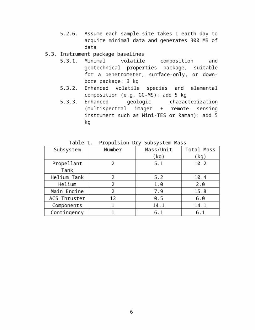
220 Awaiting Sunlight Dark 221 Awaiting Sunlight Dark 222 Awaiting Sunlight Dark 223 Awaiting Sunlight Dark 224 Awaiting Sunlight Dark 225 Charge Batteries, Travel to Site 20 (Shackleton) Light 226 Charge Batteries, Travel to Site 20 (Shackleton) Light 227 Charge Batteries, Travel to Site 20 (Shackleton) Light 228 Charge Batteries, Travel to Site 20 (Shackleton) Light 229 Charge Batteries, Travel to Site 20 (Shackleton) Light 230 Charge Batteries, Travel to Site 20 (Shackleton) Light 231 Charge Batteries, Travel to Site 20 (Shackleton) Light 232 Charge Batteries, Travel to Site 20 (Shackleton) Light 233 Charge Batteries, Travel to Site 20 (Shackleton) Light 234 Charge Batteries, Travel to Site 20 (Shackleton) Light 235 Charge Batteries, Travel to Site 20 (Shackleton) Light 236 Charge Batteries, Travel to Site 20 (Shackleton) Light 237 Charge Batteries, Travel to Site 20 (Shackleton) Light 238 Charge Batteries, Travel to Site 20 (Shackleton) Light 239 Awaiting Sunlight Dark 240 Awaiting Sunlight Dark 241 Awaiting Sunlight Dark 242 Awaiting Sunlight Dark 243 Awaiting Sunlight Dark 244 Awaiting Sunlight Dark 245 Awaiting Sunlight Dark 246 Awaiting Sunlight Dark 247 Awaiting Sunlight Dark 248 Awaiting Sunlight Dark 249 Awaiting Sunlight Dark 250 Awaiting Sunlight Dark 251 Awaiting Sunlight Dark 252 Awaiting Sunlight Dark 253 Charge Batteries, Travel to Site 20 (Shackleton) Light 254 Charge Batteries, Travel to Site 20 (Shackleton) Light 255 Charge Batteries, Travel to Site 20 (Shackleton) Light 256 Charge Batteries, Travel to Site 20 (Shackleton) Light 257 Charge Batteries, Travel to Site 20 (Shackleton) Light 258 Charge Batteries, Travel to Site 20 (Shackleton) Light 259 Charge Batteries, Travel to Site 20 (Shackleton) Light 260 Charge Batteries, Travel to Site 20 (Shackleton) Light 261 Charge Batteries, Travel to Site 20 (Shackleton) Light 262 Charge Batteries, Travel to Site 20 (Shackleton) Light 263 Charge Batteries, Travel to Site 20 (Shackleton) Light 264 Charge Batteries, Travel to Site 20 (Shackleton) Light 265 Charge Batteries, Travel to Site 20 (Shackleton) Light 266 Charge Batteries, Travel to Site 20 (Shackleton) Light 267 Awaiting Sunlight Dark 268 Awaiting Sunlight Dark 269 Awaiting Sunlight Dark
37
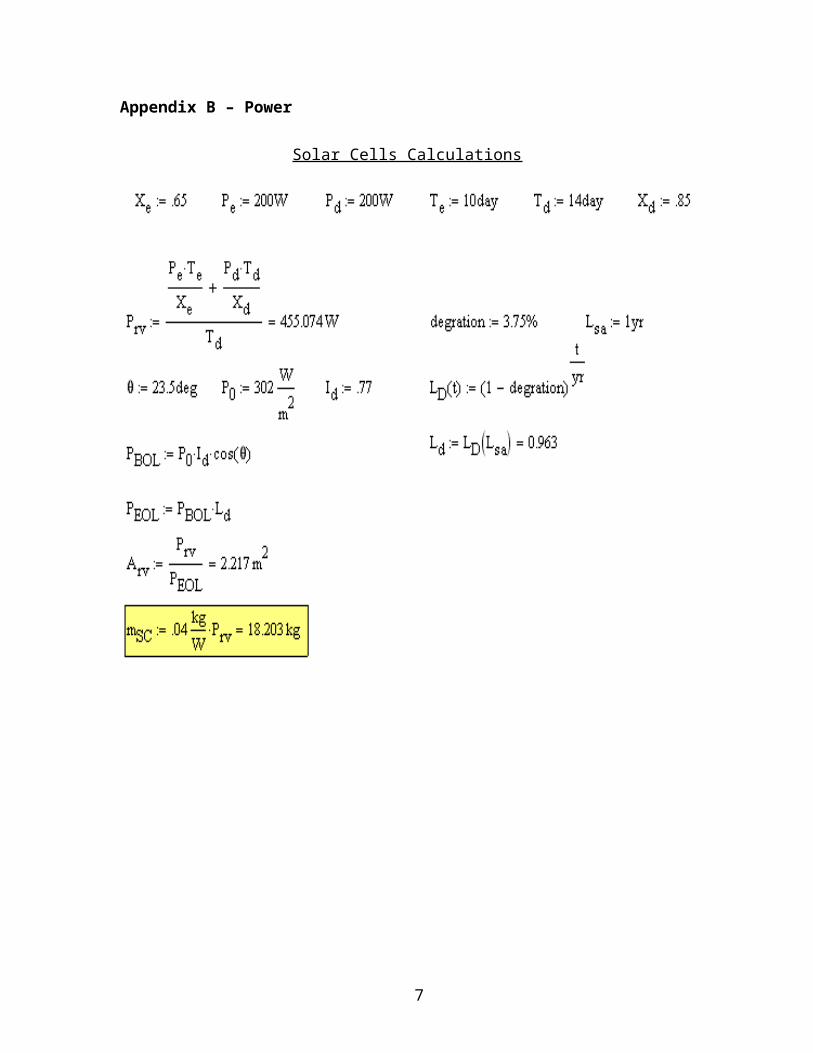
270 Awaiting Sunlight Dark 271 Awaiting Sunlight Dark 272 Awaiting Sunlight Dark 273 Awaiting Sunlight Dark 274 Awaiting Sunlight Dark 275 Awaiting Sunlight Dark 276 Awaiting Sunlight Dark 277 Awaiting Sunlight Dark 278 Awaiting Sunlight Dark 279 Awaiting Sunlight Dark 280 Awaiting Sunlight Dark 281 Charge Batteries, Travel to Site 20 (Shackleton) Light 282 Charge Batteries, Travel to Site 20 (Shackleton) Light 283 Charge Batteries, Travel to Site 20 (Shackleton) Light 284 Charge Batteries, Travel to Site 20 (Shackleton) Light 285 Charge Batteries, Travel to Site 20 (Shackleton) Light 286 Charge Batteries, Travel to Site 20 (Shackleton) Light 287 Charge Batteries, Travel to Site 20 (Shackleton) Light 288 Charge Batteries, Travel to Site 20 (Shackleton) Light 289 Charge Batteries, Travel to Site 20 (Shackleton) Light 290 Charge Batteries, Travel to Site 20 (Shackleton) Light 291 Charge Batteries, Travel to Site 20 (Shackleton) Light 292 Charge Batteries, Travel to Site 20 (Shackleton) Light 293 Charge Batteries, Travel to Site 20 (Shackleton) Light 294 Charge Batteries, Travel to Site 20 (Shackleton) Light 295 Travel to Site 20 (Shackleton) Dark Battery296 Site 20 (Shackleton) Experiments, Send Site 20 Data Dark Dark 15 Battery297 Send Site 20 Data Dark Battery298 Send Site 20 Data Dark Battery299 Send Site 20 Data Dark Battery300 Send Site 20 Data Dark Battery
301Complete Site 20 Data Transfer, Launch SRV, End of Mission Dark Battery
38
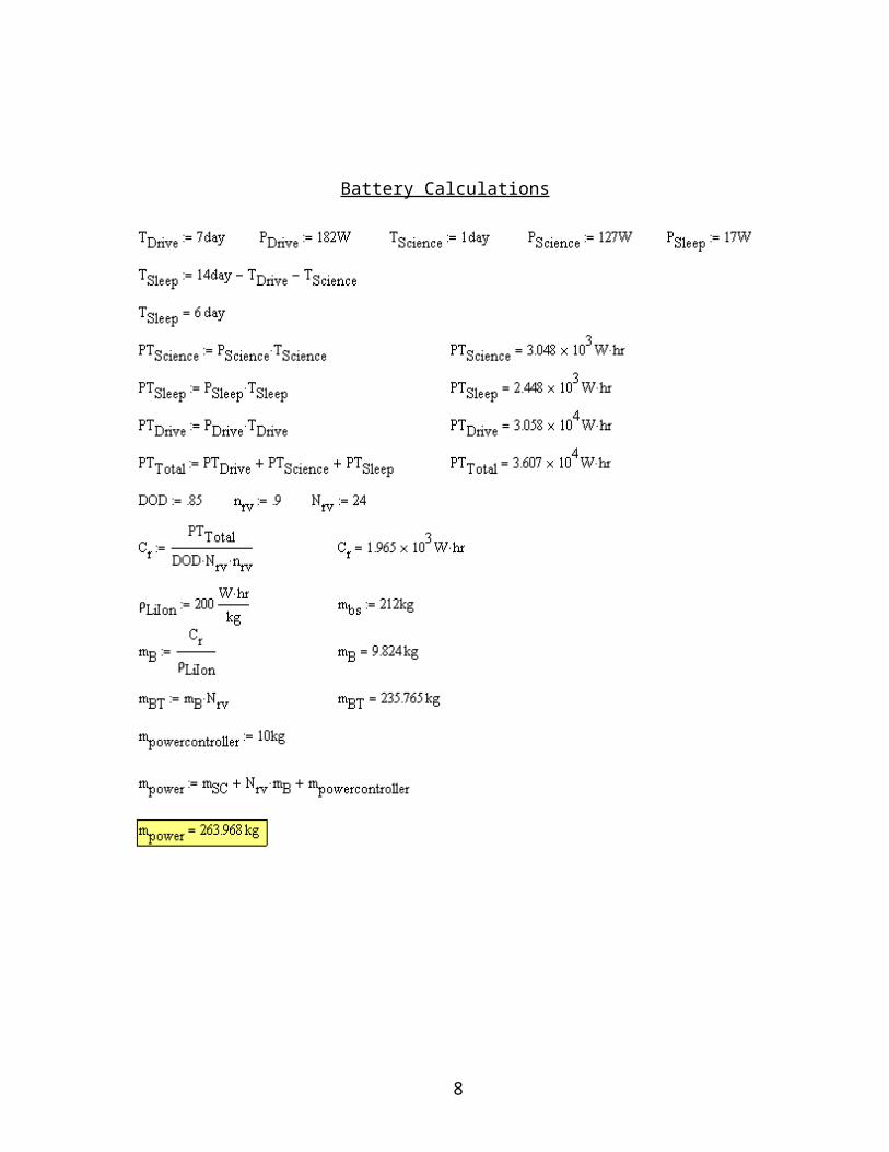
Appendix J - Level II Requirements
1. Power subsystem level II requirements1.1. The LOW Landing phase will divide up the power to the subsystems.
1.1.1. The LOW will require no more then 130 We average during the Landing phase
1.1.2. The LOW Thermal subsystem will require no more then 40 We average during the Landing phase.
1.1.3. The LOW GN&C subsystem will require no more then 50 We average during the Landing phase.
1.1.4. The LOW POWER subsystem will require no more then 10 We average during the Landing phase.
1.1.5. The LOW C&DH subsystem will require no more then 2 We average during the Landing phase.
1.1.6. The LOW Communications subsystem will require no more then 2 We average during the Landing phase.
1.1.7. The LOW Propulsion subsystem will require no more then 5 We average during the Landing phase.
1.1.8. The LOW Mobility subsystem will require no more then 4 We average during the Landing phase.
1.1.9. The LOW Mechanisms subsystem will require no more then 4 We average during the Landing phase.
1.1.10. The LOW Payload subsystem will require no more then 2 We average during the Landing phase.
1.1.11. The LOW SRV subsystem will require no more then 1 We average during the Landing phase.
1.2. The LOW Initializing phase will divide up the power to the subsystems1.2.1. The LOW will require no more then 150 We average during the
Initializing phase.1.2.2. The LOW Thermal subsystem will require no more then 40 We average
during the Initializing phase.1.2.3. The LOW GN&C subsystem will require no more then 2 We average
during the Initializing phase.1.2.4. The LOW Power subsystem will require no more then 10 We average
during the Initializing phase.1.2.5. The LOW C&DH subsystem will require no more then 20 We average
during the Initializing phase.1.2.6. The LOW Communications subsystem will require no more then 30 We
average during the Initializing phase.1.2.7. The LOW Mobility subsystem will require no more then 10 We average
during the Initializing phase.1.2.8. The LOW Mechanisms subsystem will require no more then 2 We average
during the Initializing phase.
39
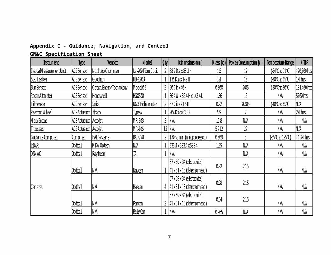
1.2.9. The LOW Payload subsystem will require no more then 2 We average during the Initializing phase.
1.2.10. The LOW SRV subsystem will require no more then 1 We average during the Initializing phase.
1.3. The LOW Driving phase will divide up the power to the subsystems.1.3.1. The LOW Will require no more then 200 We average during the Driving
phase1.3.2. The LOW Thermal subsystem will require no more then 40 We average
during the Driving phase.1.3.3. The LOW GN&C subsystem will require no more then 23 We average
during the Driving phase.1.3.4. The LOW Power subsystem will require no more then 10 We average
during the Driving phase.1.3.5. The LOW C&DH subsystem will require no more then 5 We average
during the Driving phase.1.3.6. The LOW Communications subsystem will require no more then 2 We
average during the Driving phase.1.3.7. The LOW Mobility subsystem will require no more then 100 We average
during the Driving phase.1.3.8. The LOW mechanisms subsystem will require no more then 2 We average
during the Driving phase.1.3.9. The LOW Payload subsystem will require no more then 2 We average
during the Driving phase.1.3.10. The LOW SRV subsystem will require no more then 1 We average during
the Driving phase.
1.4. The LOW Science phase will divide up the power to the subsystems.1.4.1. The LOW Will require no more then 200 We average during the Science
phase1.4.2. The LOW Thermal subsystem will require no more then 40 We average
during the Science phase.1.4.3. The LOW GN&C subsystem will require no more then 15 We average
during the Science phase.1.4.4. The LOW Power subsystem will require no more then 10 We average
during the Science phase.1.4.5. The LOW C&DH subsystem will require no more then 20 We average
during the Science phase.1.4.6. The LOW Communications subsystem will require no more then 2 We
average during the Science phase.1.4.7. The LOW Mobility subsystem will require no more then 10 We average
during the Science phase.1.4.8. The LOW Mechanisms subsystem will require no more then 1 We average
during the Science phase.1.4.9. The LOW Payload subsystem will require no more then 75 We average
during the Science phase.
40
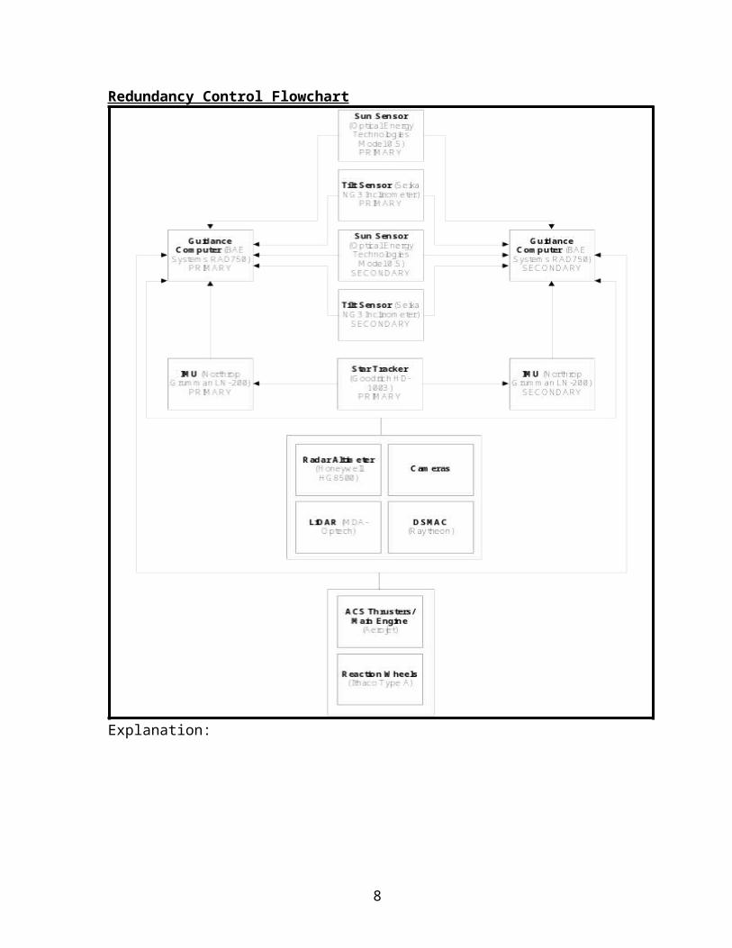
1.4.10. The LOW SRV subsystem will require no more then 1 We average during the Science phase.
1.5. The LOW Communications phase will divide up the power to the subsystems.1.5.1. The LOW will require no more then 200 We average during the
Communications.1.5.2. The LOW Thermal subsystem will require no more then 40 We average
during the Communications phase.1.5.3. The LOW GN&C subsystem will require no more then 10 We average
during the Communications phase.1.5.4. The LOW Power subsystem will require no more then 10 We average
during the Communications phase.1.5.5. The LOW Thermal subsystem will require no more then 40 We average
during the Communications phase.1.5.6. The LOW C&DH subsystem will require no more then 20 We average
during the Communications phase.1.5.7. The LOW Communications subsystem will require no more then 30 We
average during the Communications phase.1.5.8. The LOW Mobility subsystem will require no more then 10 We average
during the Communications phase.1.5.9. The LOW Mechanisms subsystem will require no more then 2 We average
during the Communications phase.1.5.10. The LOW payload subsystem will require no more then 2 We average
during the Communications phase.1.5.11. The LOW SRV subsystem will require no more then 1 We average during
the Communications phase.
1.6. The LOW Sleep phase will divide up the power to the subsystems.1.6.1. The LOW will require no more then 20 We average during the Sleep
phase.1.6.2. The LOW Thermal subsystem will require no more then 10 We average
during the Sleep phase.1.6.3. The LOW GN&C subsystem will require no more then 1 We average
during the Sleep phase.1.6.4. The LOW Power subsystem will require no more then 1 We average
during the Sleep phase.1.6.5. The LOW C&DH subsystem will require no more then 1 We average
during the Sleep phase.1.6.6. The LOW Communications subsystem will require no more then 1 We
average during the Sleep phase.1.6.7. The LOW Mobility subsystem will require 0 We average during the Sleep
phase.1.6.8. The LOW Mechanisms subsystem will require no more then 1 We average
during the Sleep phase.1.6.9. The LOW Payload subsystem will require no more then 1 We average
during the Sleep phase.
41
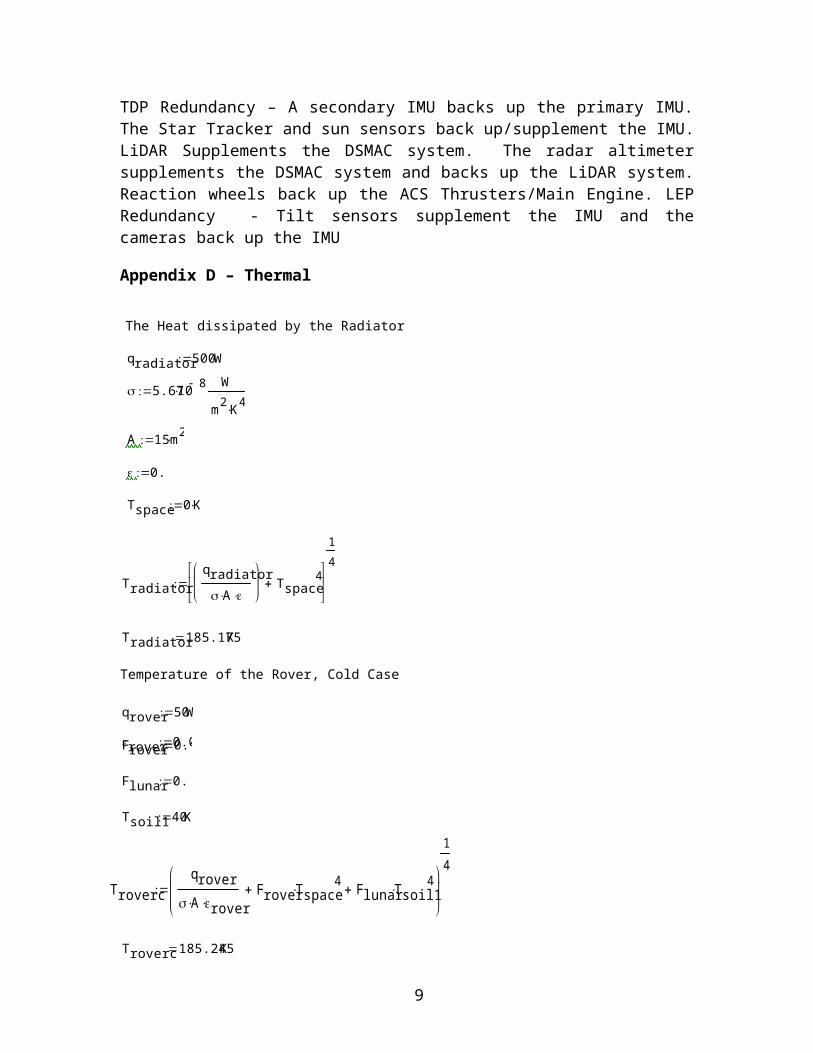
1.6.10. The LOW SRV subsystem will require no more then 1 We average during the Sleep phase.
1.7. The LOW EoM & SRV phase will divide up the power to the subsystems.1.7.1. The LOW will require no more then 100 We average during the EoM &
SRV phase.1.7.2. The LOW Thermal subsystem will require no more then 2 We average
during the EoM & SRV phase.1.7.3. The LOW GN&C subsystem will require no more then 10 We average
during the E0M & SRV phase.1.7.4. The LOW Power subsystem will require no more then 10 We average
during the E0M & SRV phase.1.7.5. The LOW C&DH subsystem will require no more then 40 We average
during the E0M & SRV phase.1.7.6. The LOW Communications subsystem will require no more then 2 We
average during the E0M & SRV phase.1.7.7. The LOW Mobility subsystem will require 10 We average during the E0M
& SRV phase.1.7.8. The LOW Mechanisms subsystem will require no more then 2 We average
during the E0M & SRV phase.1.7.9. The LOW Payload subsystem will require no more then 10 We average
during the E0M & SRV phase.1.7.10. The LOW SRV subsystem will require no more then 10 We average
during the E0M & SRV phase.
1.8. The LOW will require Solar cells1.8.1. The LOW Solar Cell’s mass will be no more the 20 kg1.8.2. The LOW Solar Cells Area will be no more the 5m2 and no less then 3m2
1.8.3. The LOW Solar Cells worst case output must be not below 455 W
1.9. The LOW will require 24 Lithium-Ion batteries1.9.1. The LOW Lithium-Ion battery’s mass total not be more then 240 kg
1.9.1.1. The LOW Lithium-Ion battery’s mass each not be more the 10 kg1.9.2. The LOW Lithium-Ion battery’s capacity total not be less then 48 KWe-hr
1.9.2.1. The LOW Lithium-Ion battery’s capacity can be less then 2 kWe-hr1.10.The LOW Will require a PCS
1.10.1. The LOW PCS mass is required to be no more than 10 kg1.10.2. The LOW PCS power usage is to be no more than 7 We
1.11.The LOW will require Teflon insulated power cables1.11.1. The LOW power cables will be required to transmit up to 30V1.11.2. The LOW power cables total length is required to be no more than 201.11.3. The LOW power cables total mass is required to be no more than 15 kg
42

2. Payload level II requirements2.1. The LOW will require a stereo imaging system.
2.1.1. The LOW’s stereo imaging system will require a mass of 0.8 kg.2.1.2. The LOW’s stereo imaging system will require power of 6.0 W.2.1.3. The LOW’s stereo imaging system will include cameras.2.1.4. The LOW’s stereo imaging system will be capable of taking 360° pictures.2.1.5. The LOW’s stereo imaging system will require a mast.
2.1.5.1. The LOW’s mast will require a mass of 3.5 kg.2.1.5.2. The LOW’s mast will require power of 9.5 W.2.1.5.3. The LOW’s mast will be deployed once at the initial site.
2.1.6. The LOW’s stereo imaging system will require a illumination system.2.1.6.1. The LOW’s illumination system will have four bulbs at 0.1 kg each.2.1.6.2. The LOW’s illumination system will require a total mass of 0.4 kg.2.1.6.3. The LOW’s illumination system will require power of 1.0 W.
2.2. The LOW’s illumination system will be used as needed for dark imaging.
2.3. The LOW will require a beacon for navigation reference.2.3.1. The LOW’s beacon will require a mass of 1.0 kg.2.3.2. The LOW’s beacon will require power of 5.0 W.2.3.3. The LOW’s beacon will be activated when needed.
2.4. The LOW will require a drill system.2.4.1. The LOW’s drill system will require a mass of 20.0 kg.2.4.2. The LOW’s drill system will require power of 30.0 W.2.4.3. The LOW’s drill system will be capable of recovering regolith from a
depth of up to 2 m.2.4.4. The LOW’s drill system will require a belly cam.
2.4.4.1. The LOW’s belly cam will require a mass of 0.4 kg.2.4.4.2. The LOW’s belly cam will require power of 3.8 W.2.4.4.3. The LOW’s belly cam will be capable of imaging the drill interface
with surface.
2.5. The LOW will require a scoop.2.5.1. The LOW’s scoop will require a mass of 0.5 kg.2.5.2. The LOW’s scoop will be capable of recovering regolith from the surface.
2.6. The LOW will require an XRD / XRF system.2.6.1. The LOW’s XRD / XRF system will require a mass of 2.0 kg.2.6.2. The LOW’s XRD / XRF system will require power of 10.0 W.2.6.3. The LOW’s XRD / XRF system will be capable of determining the
mineralogy and chemistry of the regolith.
2.7. The LOW will require geotechnical experiments2.7.1. The LOW’s geotechnical experiments will require a bearing plate with a
mass of 1.0 kg.
43
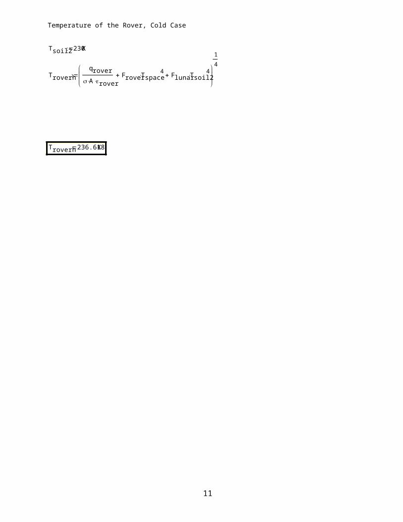
2.7.2. The LOW’s geotechnical experiments will require three cone penetrometers with a total mass of 1.5 kg.
2.7.3. The LOW’s geotechnical experiments will require a shear vane of with a mass of 0.5 kg.
2.7.4. The LOW’s geotechnical experiments will be capable of determining geotechnical properties such as soil cohesiveness, density, packing, moisture, and heat.
2.8. The LOW will require an gamma ray spectrometer.2.8.1. The LOW’s gamma ray spectrometer will require a mass of 8.6 kg.2.8.2. The LOW’s gamma ray spectrometer will detect the presence of thorium
and uranium.
2.9. The LOW will require two arms.2.9.1. Each of the LOW’s arms will require a mass of 13.0 kg.2.9.2. Each of the LOW’s arms will require power of 43.0 W.2.9.3. One of the LOW’s arms will be capable of controlling the scoop and the
geotechnical experiments and loading the SRV.2.9.4. One of the LOW’s arms will be capable of controlling the Gamma Ray
Spectrometer and the XRD / XRF.
2.10.The LOW will require a photoemission spectrometer (PES).2.10.1. The LOW’s PES will require a mass of 3.0 kg.2.10.2. The LOW’s PES will be capable of measuring electrons emitted from the
surface.2.10.3. The LOW’s PES will be deployed at the first site.
2.11.The LOW will require a photoelectric system.2.11.1. The LOW’s photoelectric system will require a mass of 1.0 kg.2.11.2. The LOW’s photoelectric system will be capable of determining the
intensity of light.2.11.3. The LOW’s photoelectric system will be deployed at the first site.
2.12.The LOW will require an emission spectrometer.2.12.1. The LOW’s emission spectrometer will require a mass of 3.0 kg.2.12.2. The LOW’s emission spectrometer will require power of 7.0 W.2.12.3. The LOW’s emission spectrometer will be capable of determining the
chemical composition from micrometeoric impact flashes. mast will be deployed once at the initial site.
2.12.4. The LOW’s emission spectrometer will be deployed at the first site.
2.13.The LOW will require a witness plate.2.13.1. The LOW’s witness plate will require a mass of 1.0 kg.2.13.2. The LOW’s witness plate will be used to observe micrometeorite impacts.
44
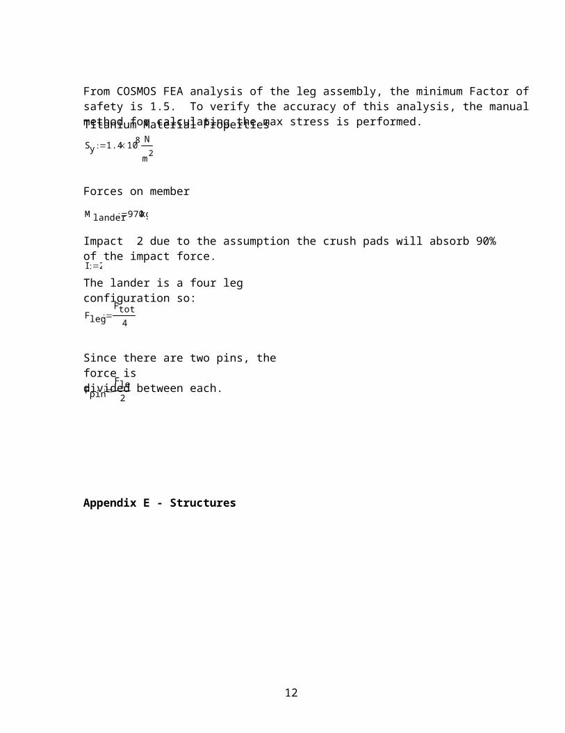
2.14.The LOW will require a langmuir probe.2.14.1. The LOW’s langmuir probe will require a mass of 3.0 kg.2.14.2. The LOW’s langmuir probe will require power of 5.0 W.2.14.3. The LOW’s langmuir probe will be capable of analyzing levitated dust.2.14.4. The LOW’s photoelectric system will be deployed at the first site.
2.15.The LOW will require a particle probe.2.15.1. The LOW’s langmuir probe will require a mass of 7.0 kg.2.15.2. The LOW’s langmuir probe will require power of 7.5 W.2.15.3. The LOW’s langmuir probe will be capable of analyzing levitated dust.2.15.4. The LOW’s photoelectric system will be deployed at the first site.
2.16.The LOW will require a neutron spectrometer.2.16.1. The LOW’s neutron spectrometer will require a mass of 1.0 kg.2.16.2. The LOW’s neutron spectrometer will require power of 1.8 W.2.16.3. The LOW’s neutron spectrometer will be capable of determining the H
content of regolith.2.16.4. The LOW’s photoelectric system will be deployed at the first site.
2.17.The LOW will require a Gas Chromatograph Mass Spectrometer (GCMS).2.17.1. The LOW’s GCMS will require a mass of 19.0 kg.2.17.2. The LOW’s GCMS will require power of 75.0 W.2.17.3. The LOW’s GCMS will run for four hours at each site.2.17.4. The LOW’s GCMS will analyze the compounds and composition of
regolith.
2.18.The LOW’s GCMS will require a GCMS sample processing system.2.18.1. The LOW’s GCMS sample processing system will require a mass of 1.0
kg.2.18.2. The LOW’s GCMS sample processing system will prepare regolith
samples with the GCMS.
2.19.The LOW will require a tunable diode laser.2.19.1. The LOW’s tunable diode laser will require a mass of 1.0 kg.2.19.2. The LOW’s tunable diode laser will require power of 10.0 W.2.19.3. The LOW’s tunable diode laser will determine the amount of water in
regolith.
2.20.The LOW will require an electron paramagnetic resonance spectroscope (EPRS).
2.20.1. The LOW’s EPRS will require a mass of 5.0 kg.2.20.2. The LOW’s EPRS will require power of 5.0 W.2.20.3. The LOW’s EPRS will determine the reactivity of dust.
45
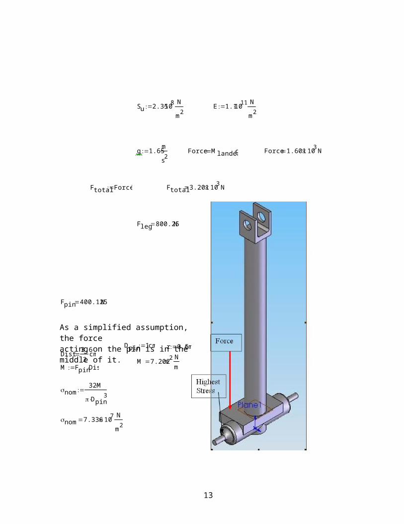
2.21.The LOW’s EPRS will require an EPRS sampling processing system.2.21.1. The LOW’s EPRS sampling processing system will require a mass of 1.0
kg.2.21.2. The LOW’s EPRS will separate regolith particles based on size (less than
and greater than 100 nm).
2.22.The LOW will require magnets.2.22.1. The LOW’s magnets will require a mass of 0.5 kg.2.22.2. The LOW’s magnets will determine the magnetic susceptibility of
regolith.
2.23.The LOW will require an IR bolometer.2.23.1. The LOW’s IR bolometer will require a mass of 2.0 kg.2.23.2. The LOW’s IR bolometer will require power of 5.0 W.2.23.3. The LOW’s IR bolometer will determine surface temperature.
2.24.The LOW will require UV imaging.2.24.1. The LOW’s UV imaging will require a mass of 5.0 kg.2.24.2. The LOW’s UV imaging will require power of 5.0 W.2.24.3. The LOW’s UV imaging view the surface of each site.
2.25.The LOW will require Helium-3 sensors.2.25.1. The LOW’s 3He sensors will determine the presence of 3He.
2.26.The LOW will require an alpha particle (AP) spectrometer.2.26.1. The LOW’s AP spectrometer will require a mass of 4.0 kg.2.26.2. The LOW’s AP spectrometer will require power of 7.0 W.2.26.3. The LOW’s AP spectrometer will detect APs emitted by radioactive gases
leaking from the lunar interior.
3. GN&C Level 2 Requirements3.1. All GN&C equipment used on the LOW must be space qualified and/or have
flight heritage in a space environment.
3.2. The GN&C must include a guidance computer with flight software where all relevant signals are relayed to and interpreted.
3.3. The GN&C subsystem must make use of an Inertial Measurement Unit in order to stabilize the LOW (during the Terminal Descent Phase) with the following constraints:
3.3.1. Must be no more than 1 kg in mass3.3.2. Must have a nominal operating power of no more than 15W3.3.3. Must have a low operating temp of at least -50 ºC and a high operating
temp of at least 70 ºC.3.3.4. MTBF (Mean Time Between Failures) of at least 20,000 hours
46
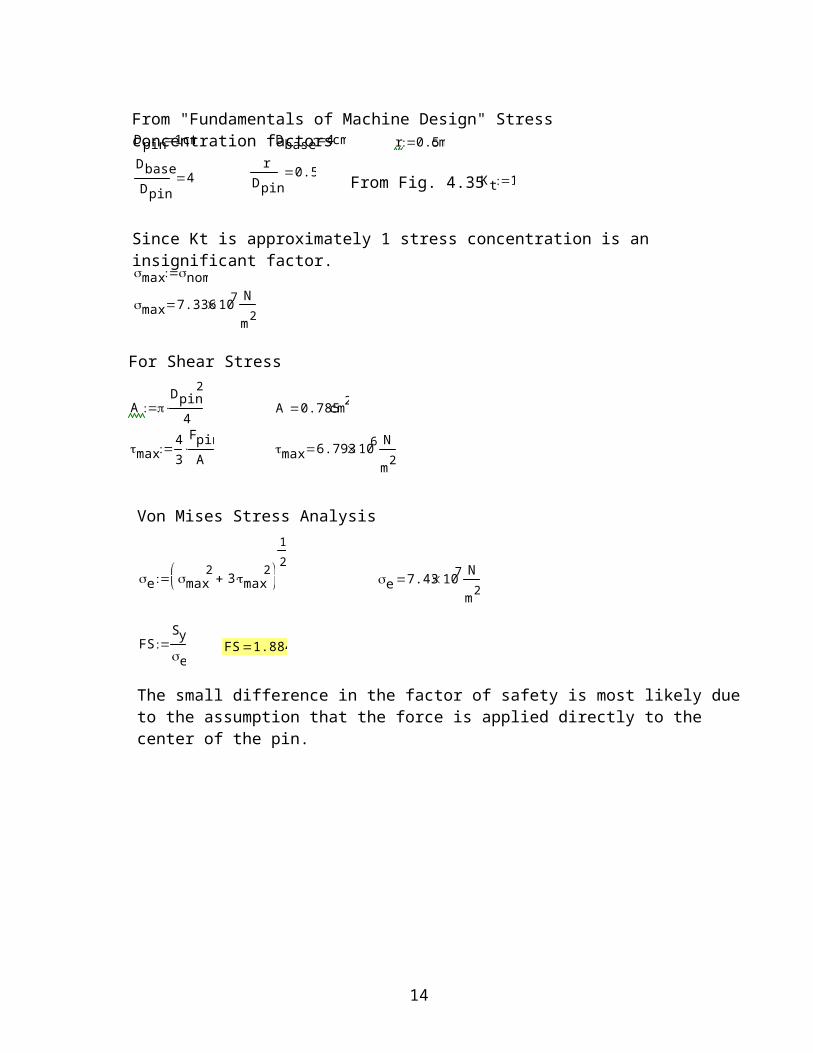
3.4. The LOW must be equipped with a star tracker in order to assist with determining its attitude. The star tracker must have the following qualities:
3.4.1. Must be no more than 3.0kg in weight3.4.2. Must not exceed 10W in operating power3.4.3. Must be able to simultaneously track at least 6 stars at one time3.4.4. Must be highly reliable – a MTBF of at least one million hours
3.5. The LOW must make use of an off-the-shelf technology to provide for a non-GPS type of navigation during descent since there is currently no GPS on the moon.
3.6. The LOW must make use of an optical remote sensing technology to determine whether or not the landing site terrain is sloped and/or hazardous.
3.7. The Lander must be equipped with a radar altimeter to determine its height above the lunar surface during descent. The following constraints are to be on said altimeter:
3.7.1. Must be no more than 2kg in mass3.7.2. Must not exceed 17W in operating power3.7.3. Must have a MTBF of at least 5000 hours
3.8. In order to assist the ACS Thrusters during the Terminal Descent Phase, the LOW must be equipped with reaction wheels capable of providing an external force, or torque, thus changing its angular momentum. Reaction wheels are to have the following constraints:
3.8.1. Must be no more than 2 kg in mass3.8.2. Must have a steady state power consumption of no more than 7W3.8.3. Must have an operational temperature range of at least -20ºC to 55 ºC.
3.9. The GN&C subsystem must provide for traversing (or navigating) the lunar terrain (Lunar Excursion Phase) by way of cameras.
3.9.1. Must be no more than 0.3 kg in mass (per camera).3.9.2. The total power used by the cameras must not exceed 20 We.
4. Structures Level 2 Requirements4.1. Viking I heritage crush pads must be manufactured and sized for the lander legs
of the LOW.
4.2. The lander ramps and the rover must utilize explosive bolts to remain secure until the LOW has safely landed on the lunar surface.
4.3. Facilities, equipment, and personnel must be in place for the construction of the large lander and rover assemblies. At a minimum, the following will be required:
4.3.1. CNC mill with a capacity to mill 3 m stock lengths of material4.3.2. CNC lathe with the capacity to turn 0.5m diameter and 1m length stock
material
47

4.3.3. Welding equipment to weld both aluminum and titanium.4.3.4. Rigs to hold up to 1m by 2m sheets on aluminum for welding
4.4. At a minimum, the following list of stock material must be available for the construction of the LOW:
4.4.1. Ramps - 0.6m2 by 10cm thick Aluminum 6061-T64.4.2. Lander Base – 2.4 m2 by 10 thick Aluminum 6061-T64.4.3. Rover Body – 5.63m2 by 10 cm thick Aluminum 6061-T64.4.4. Lander Legs
4.4.4.1. 6m x .05m Ti -6Al-4v bar stock4.4.4.2. 0.5m x 0.5m Ti -6Al-4v bar stock4.4.4.3. 5m x 0.1m x 0.1m Ti -6Al-4v plate4.4.4.4. 2m x 0.25m Ti -6Al-4v bar stock4.4.4.5. 0.5m x 0.5m x 0.25m Ti -6Al-4v plate4.4.4.6. 5m x .3m Aluminum 6061-T6 bar stock
4.5. In addition, the materials to construct the propulsion system hydrazine and helium tanks must be available.
5. Thermal Level 2 Requirements5.1. The Thermal system for the LOW must be no more than 40 kg in mass.
5.2. The total power used by the thermal system during active phase must not exceed 40We.
5.3. The total power used by the thermal system during sleep phase must not exceed 10We.
5.4. The LOW requires the use of a radiator.5.4.1. The radiator must dissipate a max of 2000 WT.5.4.2. The area of the radiator must not exceed 1m2.
5.5. The LOW requires the use heaters.5.5.1. The heaters must be connected to the heat pipes.5.5.2. The heaters must be configured in a central location.5.5.3. The mobility system must have separate heaters.
5.6. The LOW requires external heat pipes connected to batteries (-55ºC to 22ºC) to be constructed from aluminum.
5.6.1. The LOW requires the working fluid of the heat pipes to the batteries to be ammonia.
5.6.2. The LOW requires an open artery wick structure for the batteries.
5.7. The LOW requires external heat pipes connected to the electronics (0º to 40ºC) to be constructed from Aluminum.
48
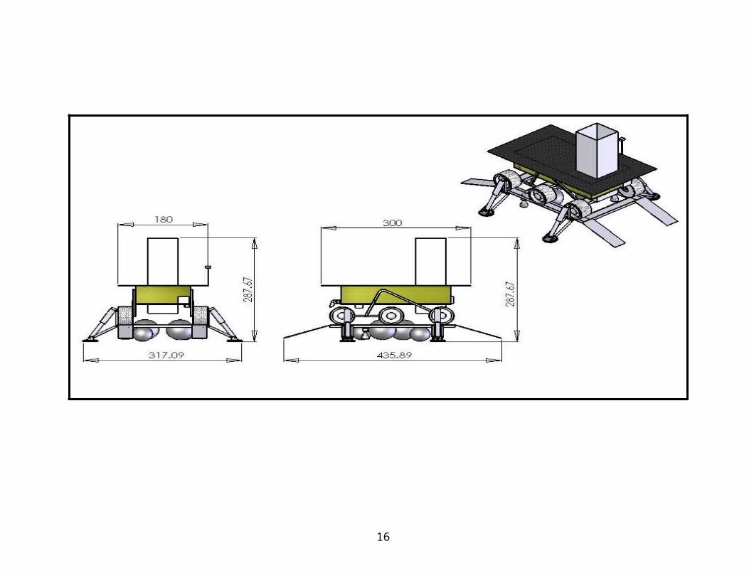
5.7.1. The LOW requires the working fluid of the heat pipes to the electronics to be ammonia.
5.7.2. The LOW requires an open artery wick structure for the electronics.
5.8. The LOW requires external heat pipes connected to the power baseplate (-10ºC to 50ºC) to be constructed from Aluminum.
5.8.1. The LOW requires the working fluid of the heat pipes to the power baseplate to be ammonia.
5.8.2. The LOW requires an open artery wick structure for the power baseplate.
5.9. The LOW requires external heat pipes connected to the C&DH (-20º to 60ºC) subsystem to be constructed from Aluminum.
5.9.1. The LOW requires the working fluid of the heat pipes to the C&DH subsystem to be ammonia.
5.9.2. The LOW requires an open artery wick structure for the C&DH subsystem.
5.10.The weight parameter for the aluminum must be 7.5 x 10⁻⁷ s2/ft2
5.11.The LOW requires a minimum of 15 MLI layers.5.11.1. MLI must have a weight per unit area of 0.021 kg/m2
6. Communications Level 2 Requirements6.1. The LOW communications subsystem must be capable of transmitting data to the
LRO6.1.1. The LOW and LRO data transfer system must be compatible6.1.2. The LOW data transfer error should be kept below 3%
6.2. The LOW communications subsystem must have a data transfer rate of at least 72,000 bits/sec
6.3. The LOW must have adequate data storage for the communications subsystem6.3.1. LOW data storage is a minimum of 300 MB6.3.2. LOW optimal data storage amount is .5 GB in order to avoid wasted time
or data loss
6.4. The LOW communications subsystem requires a maximum power of 30 W
6.5. The LOW communications subsystem must be able to operate at a bandwidth from 1700-2300 MHz
49
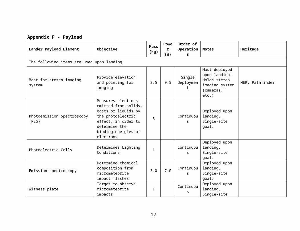
7. ConOPS Level II Requirements7.1. The LOW requires a landing procedure.
7.1.1. The LOW requires a Systems Check upon landing.7.1.2. The LOW requires an initializing phase upon landing.7.1.3. The LOW requires uploading data from earth.7.1.4. The LOW will require unloading from the landing platform.7.1.5. The LOW will require dropping a single sight box immediately upon
unloading from the landing platform ramp.7.1.6. The LOW will require the batteries are charged during the daytime.
7.2. The LOW will require beginning Site 1 experiments upon ending initializing of all systems and unloading from the landing platform ramp.
7.2.1. The LOW will require the next 5 days sending data to the LRO.
7.3. The LOW will require a Science procedure for Science Sites 2-19.7.3.1. The LOW requires no more then 4.5 days traveling to each site from the
previous.7.3.2. The LOW requires no more then 1 day at each science site.7.3.3. The LOW requires powering into sleep phase upon reaching a site but
waiting for sunlight.7.3.4. The LOW requires 5 days including the Science days to send data to the
LRO.7.3.5. The LOW requires 14 days to charge the batteries during sunlight.
7.4. The LOW will require a special procedure for Science site 20.7.4.1. The LOW requires no more then 50 days traveling to site 20.7.4.2. The LOW requires powering down in sleep phase during the dark.7.4.3. The LOW requires traveling into Shackleton for Site 20.7.4.4. The LOW will require 5 days sending data to the LRO.7.4.5. The LOW will launch the SRV at completion of the sending data.
8. Mobility Level II Requirements8.1. The Mobility mass must not be more then 100 kg.
8.2. The Mobility must be capable of traveling no less then 5 m/hr.
8.3. The Mobility must not use more then 100 We.
8.4. The Mobility requires a 6 wheel rocker bogie configuration.8.4.1. The Mobility wheels must not exceed 1m diameter.8.4.2. The Mobility must clear a height of 1 m.8.4.3. The Mobility must be capable of placing the rover’s body on the ground.
8.5. The Mobility must be capable of a 30º inclination.
8.6. The Mobility must be capable of surviving the conditions of 50 K to 400K.
50
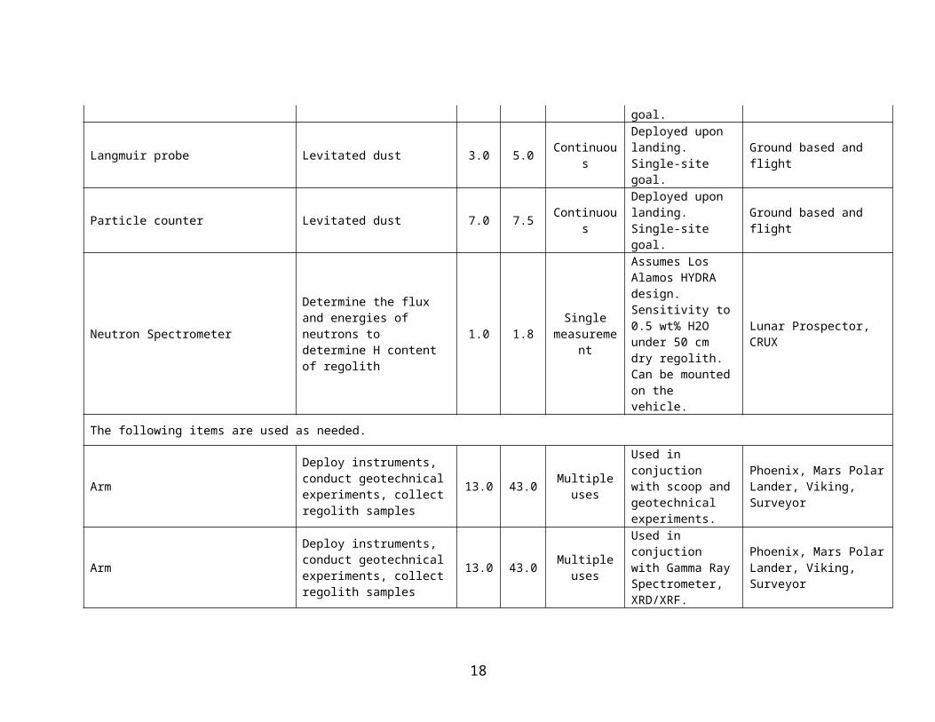
9. SRV Level 2 Requirements9.1. The LOW will require an SRV
9.2. The LOW’s SRV requires containment in a box that must not exceed 0.6m x 0.5m x 2.5m.
9.3. The LOW’s SRV requires the capability of launching no less than 1 kg of samples.
9.4. The LOW’s SRV requires accessibility from the robotic arm.
9.5. The LOW’s SRV requires not exceeding power consumption of 1We before launch phase.
9.6. The LOW’s SRV requires not exceeding power consumption of 20We during launch phase.
51
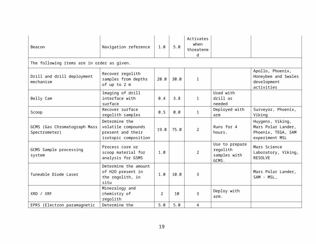
References:
Brown D. Charles. Elements of Spacecraft Design. Reston, VA: American Institute of Aeronautics and Astronautics, Inc., 20022 Brown D. Charles. Elements of Spacecraft Design. Reston, VA: American Institute of Aeronautics and Astronautics, Inc., 20023 http://en.wikipedia.org/wiki/Inertial_Measurement_Unit4 http://www.es.northropgrumman.com/solutions/ln200/assets/Inertial_Measurement_Unit_LN-2.pdfLN-200 Fiber Optic Inertial Measurement Unit5 http://science.ksc.nasa.gov/shuttle/technology/sts-newsref/sts-gnnc.htmlGuidance, Navigation, and Control. Updated 8/31/006 Quaternions and rotation Sequences: a Primer with Applications to Orbits, Aerospace, and Virtual Reality. Kuipers, Jack B., Princeton University Press copyright 19997 http://www.oss.goodrich.com/datasheets/oss/Goodrich_HD1003_StarTracker.pdf HD-1003 Star Tracker Attitude Sensor. 20048 http://www.agi.com/downloads/corporate/partners/edu/advancedSunSensorProject.pdf Attitude Determination – Advanced Sun Sensors for Pico-satellites. 9 https://www.llnl.gov/etr/pdfs/06_94.1.pdfThe Clementine Satellite. June 19940 http://www51.honeywell.com/aero/common/documents/myaerospacecatalog-documents/MilitaryAC/HG8500_Radar_Altimeter.pdfHoneywell HG8500 Series Radar Altimeter. June 13, 200311 http://trs-new.jpl.nasa.gov/dspace/bitstream/2014/15835/1/00-1598.pdfDevelopment and Validation of Reaction Wheel Disturbance Models: Empirical Model. June 28, 20012 http://mars.jpl.nasa.gov/mer/mission/tl_surface_nav_balance.htmlRover Navigation During Surface Operations. October 4, 20053 http://www-robotics.jpl.nasa.gov/publications/Mark_Maimone/maki-jgr-2003je002077.pdfMars Exploration Rover Engineering Cameras. Journal of Geophysical Research. 2003 4 http://www-robotics.jpl.nasa.gov/publications/Mark_Maimone/maki-jgr-2003je002077.pdfMars Exploration Rover Engineering Cameras. Journal of Geophysical Research. 20035 http://www.jpl.nasa.gov/news/press_kits/mplds2hq.pdfMars Polar Lander/ Deep Space 2, Press Kit Dec. 19996 http://lunar.arc.nasa.gov/results/alpha.htmALPHA PARTICLE SPECTROMETER - Oct 2, 20017 http://lunar.arc.nasa.gov/results/gamma.htmAn introduction to the gamma ray spectrometer - October 2, 20018 http://spaceflight.nasa.gov/shuttle/reference/shutref/orbiter/comm/orbcomm/sband.htmlS-Band System Curator: Kim Dismukes | Responsible NASA Official: John Ira Petty | Updated: 04/07/2002
52