Embed Size (px)
Citation preview
FINAL REPORT
Portable Digital Mouth andOcclusion Reproducer
(KSTC-144-401-07-015)
PI: Fuhua (Frank) Cheng
Department of Computer Science
College of Engineering
University of Kentucky
Tel: (859) 268-5823
Email: [email protected]
http://www.cs.engr.uky.edu/˜ cheng/
10/29/2009
Summary
This is the summary of our work during the past two and half years (June 1, 2007 - Septem-
ber 30, 2009). Technical tasks finished during this period include: the construction of a
standard model, the construction of a occlusion model, the design of a mouth scan system,
mesh simplification technique, mesh interpolation technique, mesh curvature computation
technique, mesh segmentation technique, constraint based scaling, offset surface generation
technique, a square tube mirror based imaging system, and a feature based shape recon-
struction technique. Four generations of a prototype have been built.
We consider this grant a success. Our most important achievement is the development of
an imaging system and required geometric algorithms to support 3D shape reconstruction.
We also produced two MS students (Jiaxi Wang, graduated in March 2008, and Conglin
Huang, graduated in June, 2009), 8 journal papers and 6 conference paper. A PhD student
that has been supported by this grant (Mr. Fengtao Fan) will graduate at the end of next
year.
Table of Contents
1 Introduction 1
2 Objective 2
3 Technical Tasks 3
4 Experimental Method 4
5 Results and Discussion 10
6 Commercialization Plan 136.1 Plans towards Commercialization . . . . . . . . . . . . . . . . . . . . . . . . 136.2 Strategy for short-term goal . . . . . . . . . . . . . . . . . . . . . . . . . . . 146.3 Strategy for mid-term goal . . . . . . . . . . . . . . . . . . . . . . . . . . . . 156.4 Strategy for long-term goal . . . . . . . . . . . . . . . . . . . . . . . . . . . . 15
7 Conclusions 15References16
1 Introduction
Current dental CAD/CAM systems can do 3D design of veneers, inlays/onlays, crowns/Cores,
bridges/frameworks [138]. A patient can go to a dentistry to get dental restoration service
such as the ones mentioned above in only one trip [138]. However, this is not possible if a (re-
movable) partial denture is needed, even though the current CAM technology can handle the
partial denture manufacturing process completely [96][123]. The problem is with the CAD
representation of the patient’s mouth required by the CAM system: such a representation
simply is not there. The problem is twofold.
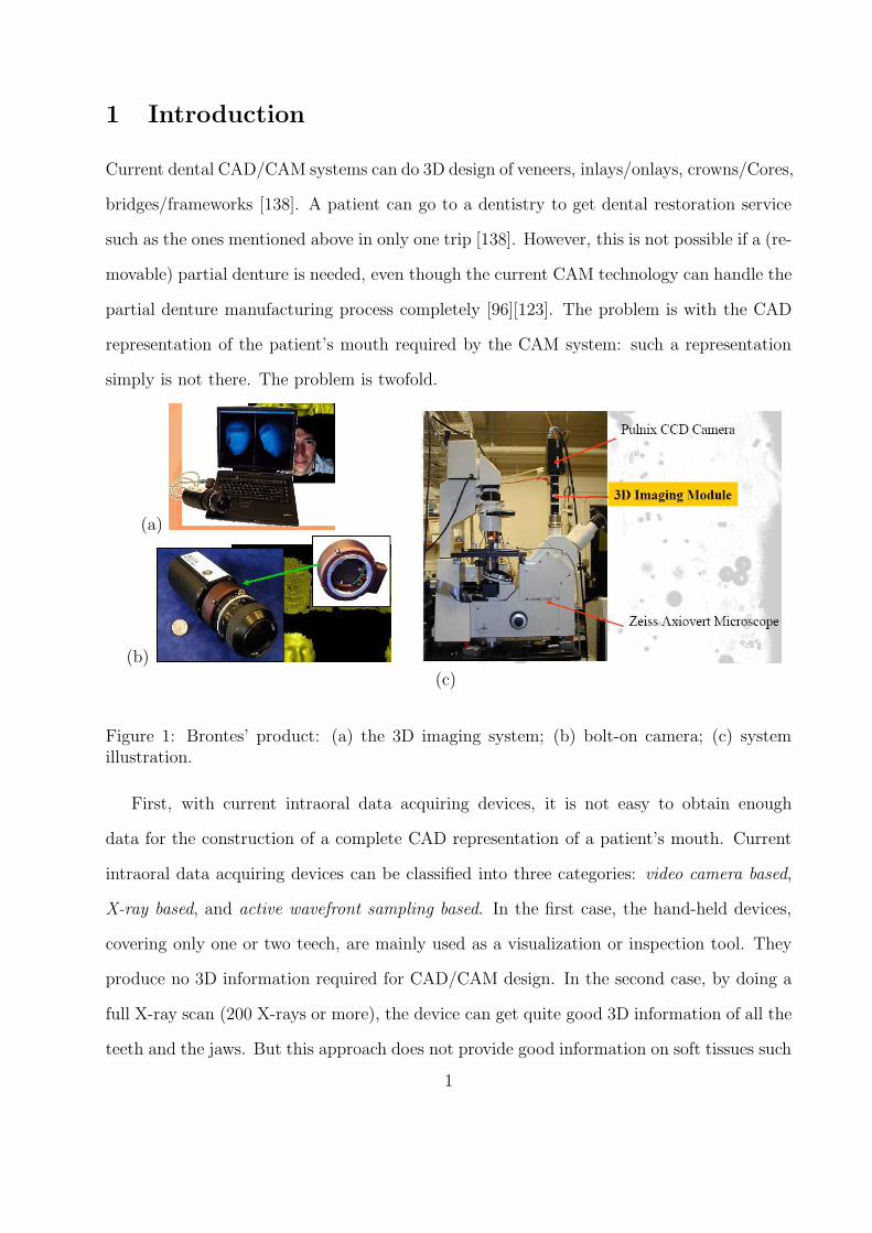
(a)
(b)
(c)
Figure 1: Brontes’ product: (a) the 3D imaging system; (b) bolt-on camera; (c) systemillustration.
First, with current intraoral data acquiring devices, it is not easy to obtain enough
data for the construction of a complete CAD representation of a patient’s mouth. Current
intraoral data acquiring devices can be classified into three categories: video camera based,
X-ray based, and active wavefront sampling based. In the first case, the hand-held devices,
covering only one or two teech, are mainly used as a visualization or inspection tool. They
produce no 3D information required for CAD/CAM design. In the second case, by doing a
full X-ray scan (200 X-rays or more), the device can get quite good 3D information of all the
teeth and the jaws. But this approach does not provide good information on soft tissues such
1
as the gums which are critical in the reconstruction of the patient’s mouth for partial denture
design. In the third case, the single-camera device can actually see in 3D. Brontes’ product
is the only product in this category [74] (see Figure 3 for the imaging system, the camera
and the system illustration of this product). However, like all the imaging systems, it can
only provide information on visible portions of an object, it can not provide informtation
on the portions of an object that it can not see. Therefore, dentists are still using the
impressing-taking approach to reproduce a patient’s mouth even though this approach has
problems such as: (1) the need of taking multiple impressions; (2) remakes and multiple
try-ins of the partial dentures due to poor quality of the impressions; (3) over extended or
under extended borders of the partial dentures; and (4) dimension instability due to alginate
shrinkage/expansion.
Second, there is not design support for compact, one-piece representation of the mouth of a
patient. CAD representations supported by current chairside CAD/CAM systems are either
mesh based or NURBS-based [145]. Mesh-based representations are expensive to maintain
and process because usually excessively large amount of vertices and faces are needed in
the representation to reach a required precision. On average, 20,000 vertices and faces are
needed in a single tooth representation in this approach [145]. The NURBS-based approach,
on the other hand, limited by the rectangular grid topology of its parameter space, can not
represent complicated shape with only one surface. Therefore, current chairside CAD/CAM
systems are hindered not only by insufficient data for the reconstruction of a mouth, but
also inefficient CAD modeling techniques in representing the mouth.
2 Objective
The goal of this project is to develop a device that is capable of reproducing the mouth
and occlusion of a patient. The device is composed of a Mouth Scan System (MSS), a flat-
panel liquid crystal display (LCD) monitor, a PC, and a set of reconstruction, modeling and
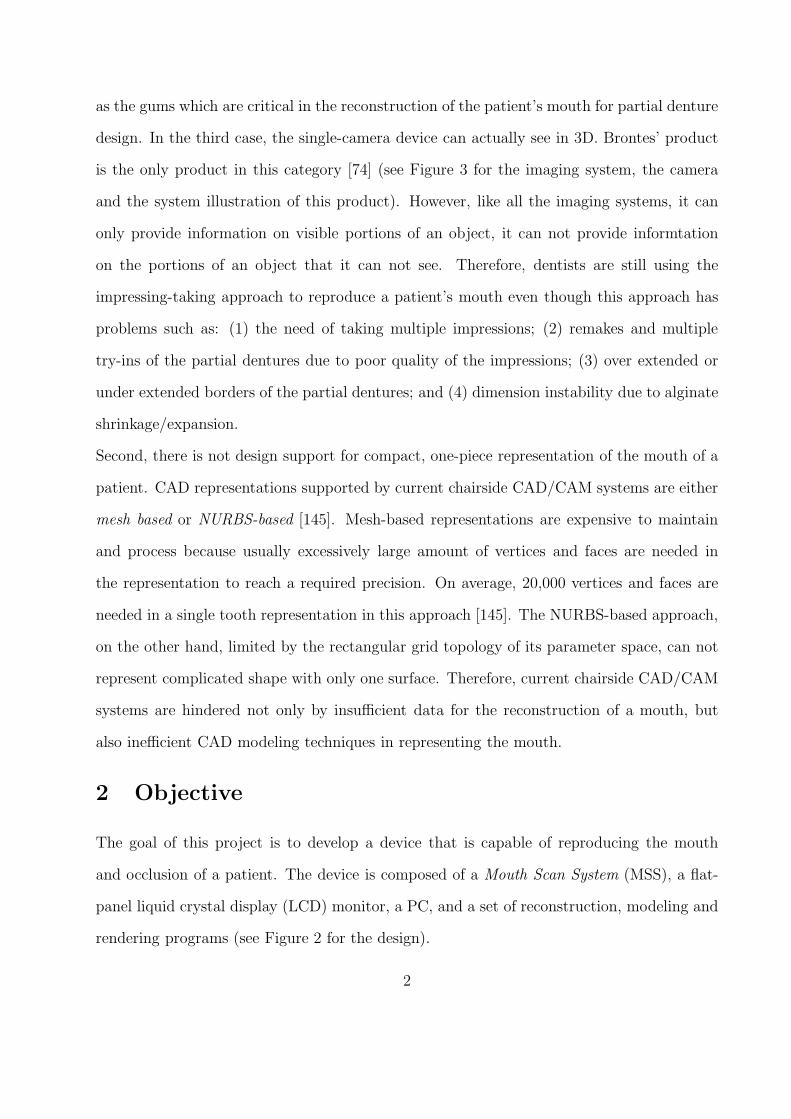
rendering programs (see Figure 2 for the design).
2
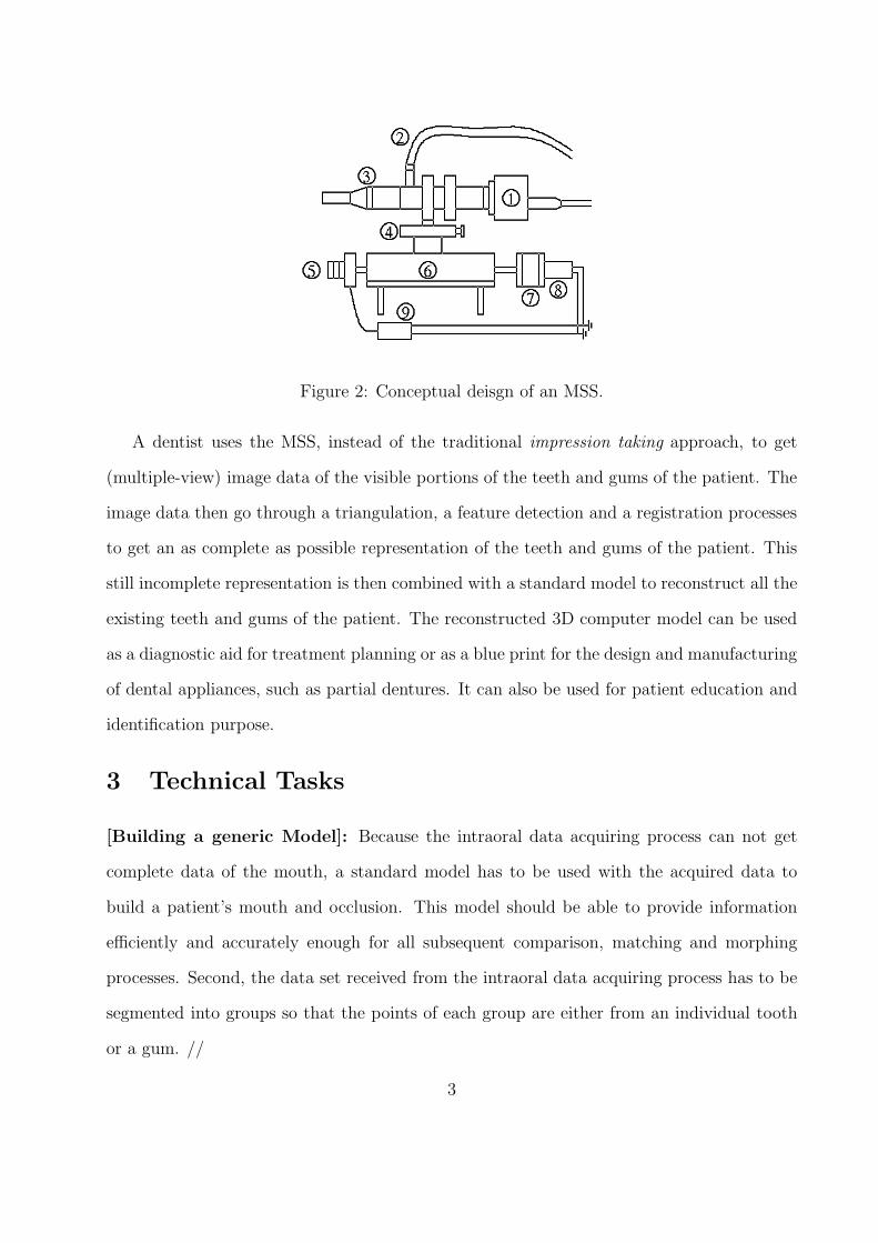
Figure 2: Conceptual deisgn of an MSS.
A dentist uses the MSS, instead of the traditional impression taking approach, to get
(multiple-view) image data of the visible portions of the teeth and gums of the patient. The
image data then go through a triangulation, a feature detection and a registration processes
to get an as complete as possible representation of the teeth and gums of the patient. This
still incomplete representation is then combined with a standard model to reconstruct all the
existing teeth and gums of the patient. The reconstructed 3D computer model can be used
as a diagnostic aid for treatment planning or as a blue print for the design and manufacturing
of dental appliances, such as partial dentures. It can also be used for patient education and
identification purpose.
3 Technical Tasks
[Building a generic Model]: Because the intraoral data acquiring process can not get
complete data of the mouth, a standard model has to be used with the acquired data to
build a patient’s mouth and occlusion. This model should be able to provide information
efficiently and accurately enough for all subsequent comparison, matching and morphing
processes. Second, the data set received from the intraoral data acquiring process has to be
segmented into groups so that the points of each group are either from an individual tooth
or a gum. //
3
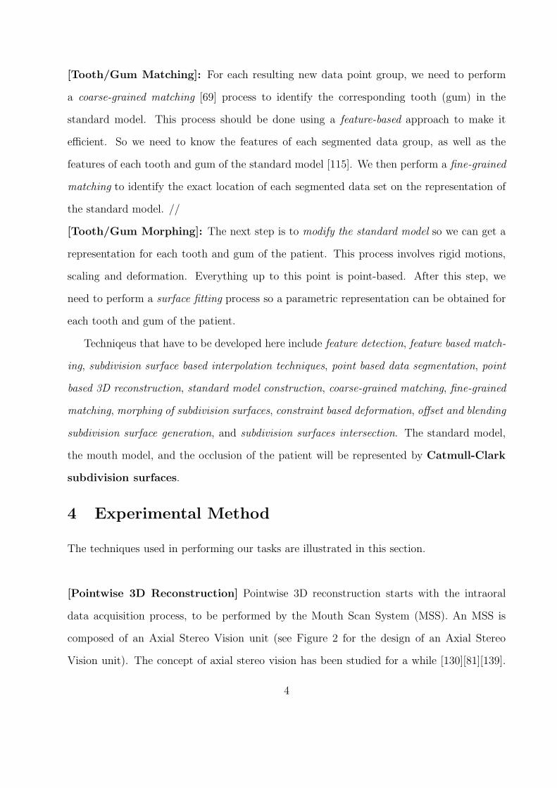
[Tooth/Gum Matching]: For each resulting new data point group, we need to perform
a coarse-grained matching [69] process to identify the corresponding tooth (gum) in the
standard model. This process should be done using a feature-based approach to make it
efficient. So we need to know the features of each segmented data group, as well as the
features of each tooth and gum of the standard model [115]. We then perform a fine-grained
matching to identify the exact location of each segmented data set on the representation of
the standard model. //
[Tooth/Gum Morphing]: The next step is to modify the standard model so we can get a
representation for each tooth and gum of the patient. This process involves rigid motions,
scaling and deformation. Everything up to this point is point-based. After this step, we
need to perform a surface fitting process so a parametric representation can be obtained for
each tooth and gum of the patient.
Techniqeus that have to be developed here include feature detection, feature based match-
ing, subdivision surface based interpolation techniques, point based data segmentation, point
based 3D reconstruction, standard model construction, coarse-grained matching, fine-grained
matching, morphing of subdivision surfaces, constraint based deformation, offset and blending
subdivision surface generation, and subdivision surfaces intersection. The standard model,
the mouth model, and the occlusion of the patient will be represented by Catmull-Clark
subdivision surfaces.
4 Experimental Method
The techniques used in performing our tasks are illustrated in this section.
[Pointwise 3D Reconstruction] Pointwise 3D reconstruction starts with the intraoral
data acquisition process, to be performed by the Mouth Scan System (MSS). An MSS is
composed of an Axial Stereo Vision unit (see Figure 2 for the design of an Axial Stereo
Vision unit). The concept of axial stereo vision has been studied for a while [130][81][139].
4
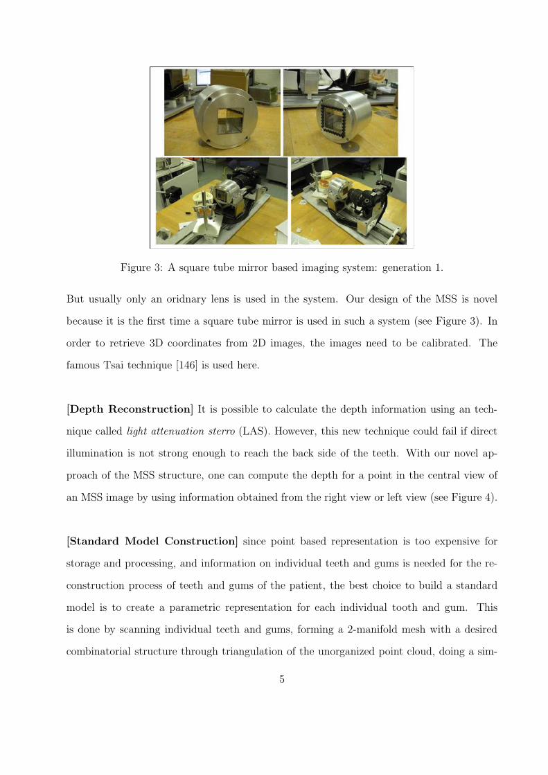
Figure 3: A square tube mirror based imaging system: generation 1.
But usually only an oridnary lens is used in the system. Our design of the MSS is novel
because it is the first time a square tube mirror is used in such a system (see Figure 3). In
order to retrieve 3D coordinates from 2D images, the images need to be calibrated. The
famous Tsai technique [146] is used here.
[Depth Reconstruction] It is possible to calculate the depth information using an tech-
nique called light attenuation sterro (LAS). However, this new technique could fail if direct
illumination is not strong enough to reach the back side of the teeth. With our novel ap-
proach of the MSS structure, one can compute the depth for a point in the central view of
an MSS image by using information obtained from the right view or left view (see Figure 4).
[Standard Model Construction] since point based representation is too expensive for
storage and processing, and information on individual teeth and gums is needed for the re-
construction process of teeth and gums of the patient, the best choice to build a standard
model is to create a parametric representation for each individual tooth and gum. This
is done by scanning individual teeth and gums, forming a 2-manifold mesh with a desired
combinatorial structure through triangulation of the unorganized point cloud, doing a sim-
5
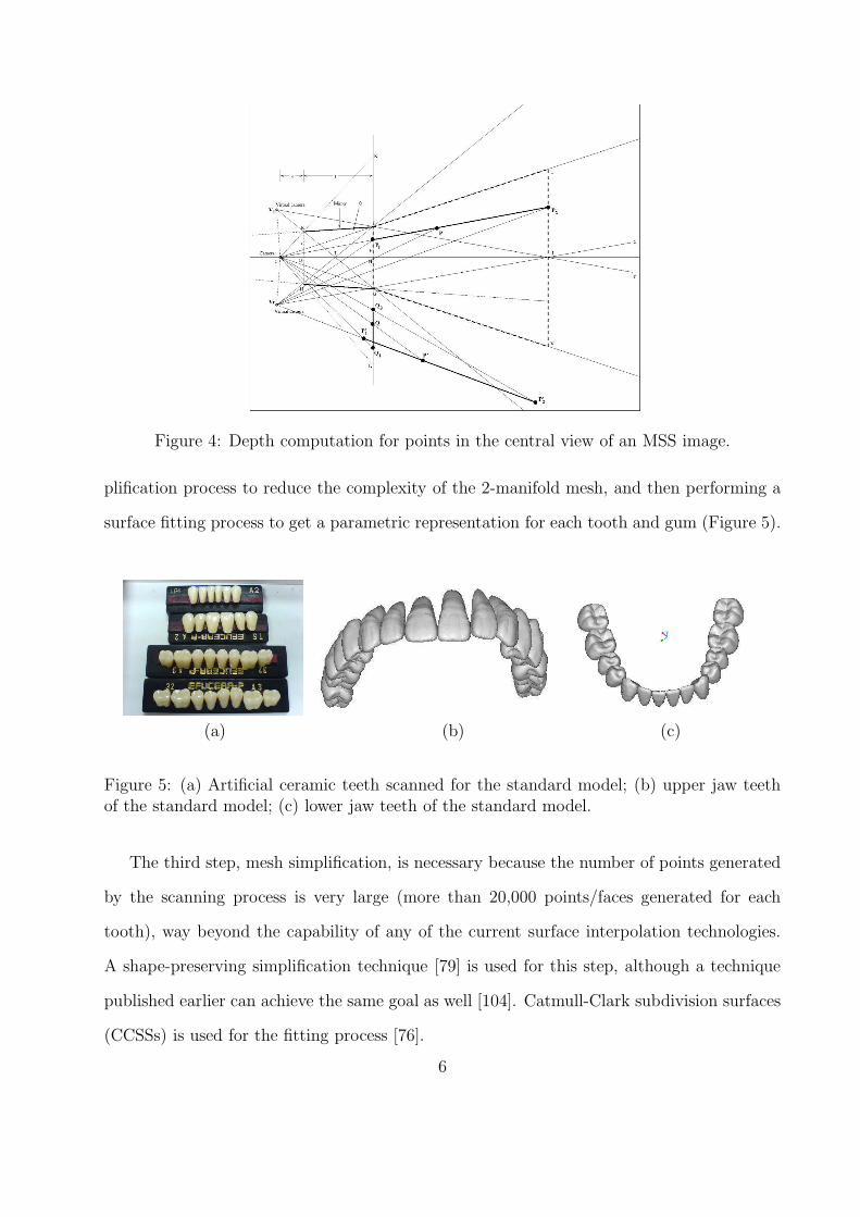
Figure 4: Depth computation for points in the central view of an MSS image.
plification process to reduce the complexity of the 2-manifold mesh, and then performing a
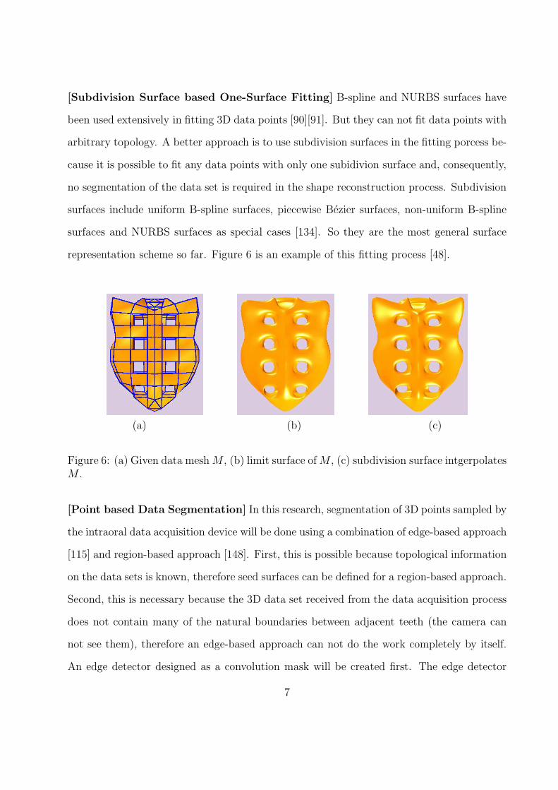
surface fitting process to get a parametric representation for each tooth and gum (Figure 5).
(a) (b) (c)
Figure 5: (a) Artificial ceramic teeth scanned for the standard model; (b) upper jaw teethof the standard model; (c) lower jaw teeth of the standard model.
The third step, mesh simplification, is necessary because the number of points generated
by the scanning process is very large (more than 20,000 points/faces generated for each
tooth), way beyond the capability of any of the current surface interpolation technologies.
A shape-preserving simplification technique [79] is used for this step, although a technique
published earlier can achieve the same goal as well [104]. Catmull-Clark subdivision surfaces
(CCSSs) is used for the fitting process [76].
6
[Subdivision Surface based One-Surface Fitting] B-spline and NURBS surfaces have
been used extensively in fitting 3D data points [90][91]. But they can not fit data points with
arbitrary topology. A better approach is to use subdivision surfaces in the fitting porcess be-
cause it is possible to fit any data points with only one subidivion surface and, consequently,
no segmentation of the data set is required in the shape reconstruction process. Subdivision
surfaces include uniform B-spline surfaces, piecewise Bezier surfaces, non-uniform B-spline
surfaces and NURBS surfaces as special cases [134]. So they are the most general surface
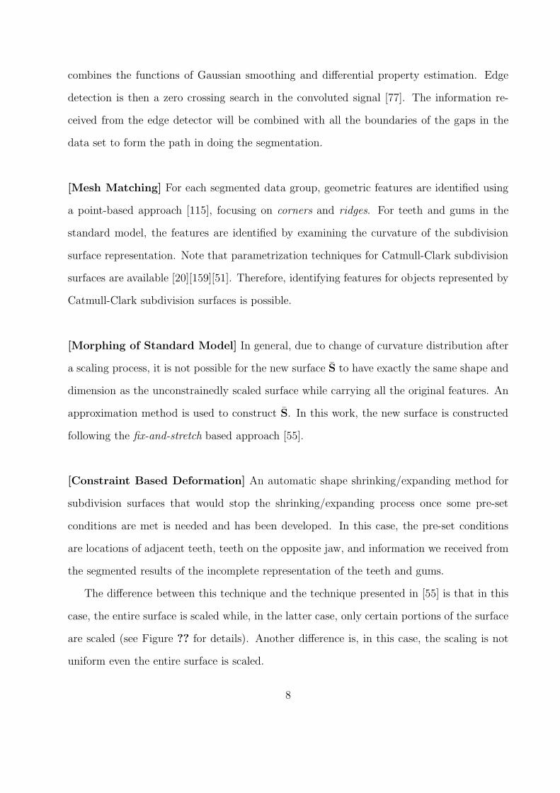
representation scheme so far. Figure 6 is an example of this fitting process [48].
(a) (b) (c)
Figure 6: (a) Given data mesh M , (b) limit surface of M , (c) subdivision surface intgerpolatesM .
[Point based Data Segmentation] In this research, segmentation of 3D points sampled by
the intraoral data acquisition device will be done using a combination of edge-based approach
[115] and region-based approach [148]. First, this is possible because topological information
on the data sets is known, therefore seed surfaces can be defined for a region-based approach.
Second, this is necessary because the 3D data set received from the data acquisition process
does not contain many of the natural boundaries between adjacent teeth (the camera can
not see them), therefore an edge-based approach can not do the work completely by itself.
An edge detector designed as a convolution mask will be created first. The edge detector
7
combines the functions of Gaussian smoothing and differential property estimation. Edge
detection is then a zero crossing search in the convoluted signal [77]. The information re-
ceived from the edge detector will be combined with all the boundaries of the gaps in the
data set to form the path in doing the segmentation.
[Mesh Matching] For each segmented data group, geometric features are identified using
a point-based approach [115], focusing on corners and ridges. For teeth and gums in the
standard model, the features are identified by examining the curvature of the subdivision
surface representation. Note that parametrization techniques for Catmull-Clark subdivision
surfaces are available [20][159][51]. Therefore, identifying features for objects represented by
Catmull-Clark subdivision surfaces is possible.
[Morphing of Standard Model] In general, due to change of curvature distribution after
a scaling process, it is not possible for the new surface S to have exactly the same shape and
dimension as the unconstrainedly scaled surface while carrying all the original features. An
approximation method is used to construct S. In this work, the new surface is constructed
following the fix-and-stretch based approach [55].
[Constraint Based Deformation] An automatic shape shrinking/expanding method for
subdivision surfaces that would stop the shrinking/expanding process once some pre-set
conditions are met is needed and has been developed. In this case, the pre-set conditions
are locations of adjacent teeth, teeth on the opposite jaw, and information we received from
the segmented results of the incomplete representation of the teeth and gums.
The difference between this technique and the technique presented in [55] is that in this
case, the entire surface is scaled while, in the latter case, only certain portions of the surface
are scaled (see Figure ?? for details). Another difference is, in this case, the scaling is not
uniform even the entire surface is scaled.
8
[Offset and Blending Subdivision Surface Generation] For a given subdivision surface
S, the work we need to do here is to create an offset surface S∗ for a specified portion of
the given surface. Our approach here is to use a combination of constrained scaling and
constrained translation to get a general offset surface generated and then use surface-surface
intersection to remove undesired portion of the surface. This approach is independent of the
topology of the base surface and, consequently, can be used for surfaces whose parameters
are not rectangular such as subdivision surfaces.
A blending surface is generated by mixing several base surfaces with appropriate weights
to form a new surface. The weight of each base surface is determined by a real-valued func-
tion called ”weightfunction” or ”blendingfunction”. The basic idea is to construct a rail
curve on both surfaces, using the surface-surface intersection technique shown below, then
build a general blending model. This is because the construction of a smoothing surface for
two intersecting surfaces requires the computation of the intersection curve in certain cases
only. The computed intersection curve does not have to be exact; a good approximation
would usually be enough. The construction of the rail curve and the blending area are per-
formed in parameter space to avoid unnecessary adjustment process. A blending technique
for the smoothing of a sharp corner shared by three faces is developed here too.
[Subdivision Surfaces Intersection] The intersection operation is performed in the pa-
rameter spaces of the subdivision surfaces, not in object space. A cubic frame buffer is
created for each closed subdivision surface (a solid: a tooth or a gum). The representation
of each tooth (gum) is voxelized first and then a volume flooding is performed to mark all
the voxels that are inside the given tooth (gum).
[Outcome Assessment] We use one metric in assessing the outcome of the innovation
research described above. We consider the outcome a good one if the relative error in each
9
case is smaller than or equal to 3% of the dimemsion of a tooth. Measuring absolute error
does not make much sense here because the dimension of a tooth is already relatively small.
The reason for using 3% for the relative error bound is because it corresponds to half a pixel
in a resolution of 1280 × 960. This bound is used both for DMR and shape representation.
5 Results and Discussion
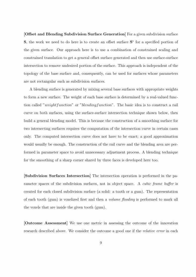
[Mouth Scan System] Our square tube mirror based imaging system has been improved
three times. Generations 2 through 4 are shown below.
Figure 7: A square tube mirror based imaging system: generation 2.
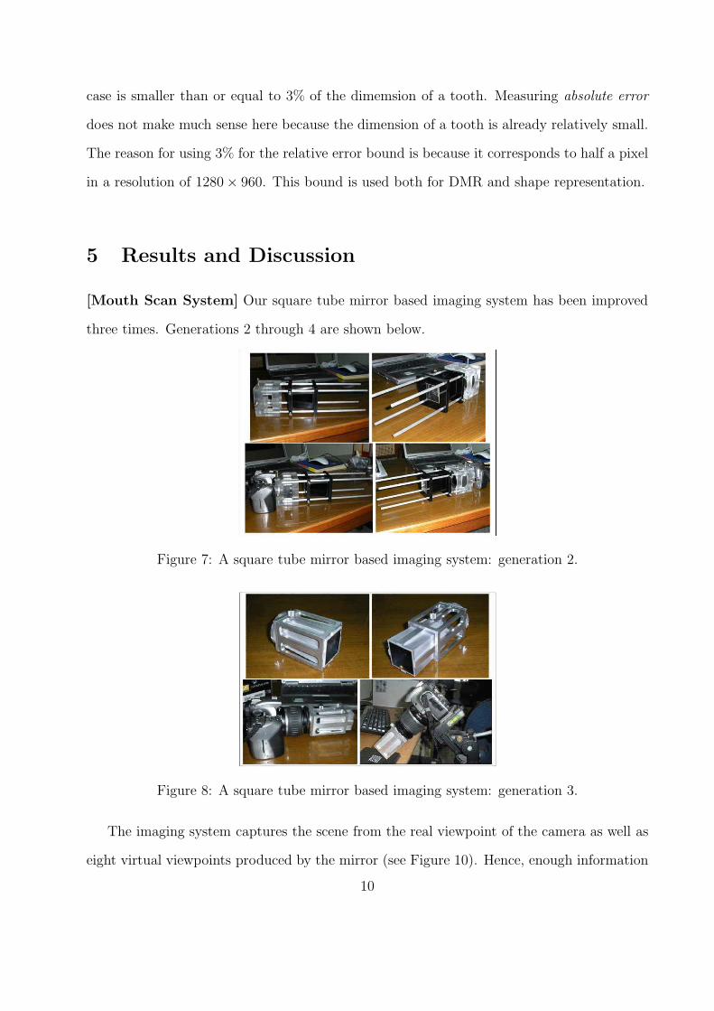
Figure 8: A square tube mirror based imaging system: generation 3.
The imaging system captures the scene from the real viewpoint of the camera as well as
eight virtual viewpoints produced by the mirror (see Figure 10). Hence, enough information
10
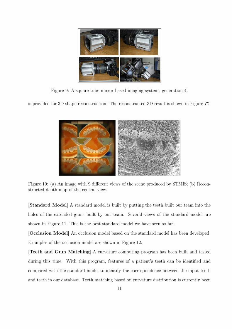
Figure 9: A square tube mirror based imaging system: generation 4.
is provided for 3D shape reconstruction. The reconstructed 3D result is shown in Figure ??.
Figure 10: (a) An image with 9 different views of the scene produced by STMIS; (b) Recon-structed depth map of the central view.
[Standard Model] A standard model is built by putting the teeth built our team into the
holes of the extended gums built by our team. Several views of the standard model are
shown in Figure 11. This is the best standard model we have seen so far.
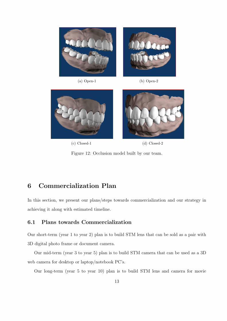
[Occlusion Model] An occlusion model based on the standard model has been developed.
Examples of the occlusion model are shown in Figure 12.
[Teeth and Gum Matching] A curvature computing program has been built and tested
during this time. With this program, features of a patient’s teeth can be identified and
compared with the standard model to identify the correspondence between the input teeth
and teeth in our database. Teeth matching based on curvature distribution is currently been
11

(a) Top-1 (b) Top-2
(c) Bottom-1 (d) Bottom-2
Figure 11: Standard model built by our team.
developed.
[Teeth and Gum Segmentation] A segmentation program has been developed. The teeth
and the gums of the standard model are segmented using this technique and the results are
shown in Figure 13. The original mesh is shown in Figure 11. Corrected We use different
colors for different teeth and gums to show the correctness of our results.
[Offset Surface Generation] An offset surface generation technique for Loop subdivision
surface has been developed.
[Outcome Assessment] We use one metric in assessing the outcome of the innovation re-
search described above. An outcome is considered a good one if the relative error in each case
is smaller than or equal to 3% of the dimemsion of a tooth. Measuring absolute error does
not make much sense here because the dimension of a tooth is already relatively small. The
reason for using 3% for the relative error bound is because it corresponds to half a pixel in
a resolution of 1280×960. This bound has been used for both DMR and shape representation.
12
(a) Open-1 (b) Open-2
(c) Closed-1 (d) Closed-2
Figure 12: Occlusion model built by our team.
6 Commercialization Plan
In this section, we present our plans/steps towards commercialization and our strategy in
achieving it along with estimated timeline.
6.1 Plans towards Commercialization
Our short-term (year 1 to year 2) plan is to build STM lens that can be sold as a pair with
3D digital photo frame or document camera.
Our mid-term (year 3 to year 5) plan is to build STM camera that can be used as a 3D
web camera for desktop or laptop/notebook PC’s.
Our long-term (year 5 to year 10) plan is to build STM lens and camera for movie
13
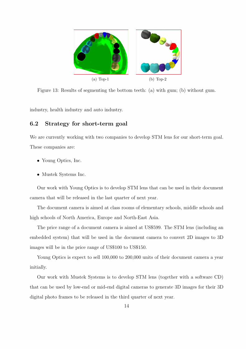
(a) Top-1 (b) Top-2
Figure 13: Results of segmenting the bottom teeth: (a) with gum; (b) without gum.
industry, health industry and auto industry.
6.2 Strategy for short-term goal
We are currently working with two companies to develop STM lens for our short-term goal.
These companies are:
• Young Optics, Inc.
• Mustek Systems Inc.
Our work with Young Optics is to develop STM lens that can be used in their document
camera that will be released in the last quarter of next year.
The document camera is aimed at class rooms of elementary schools, middle schools and
high schools of North America, Europe and North-East Asia.
The price range of a document camera is aimed at US$599. The STM lens (including an
embedded system) that will be used in the document camera to convert 2D images to 3D
images will be in the price range of US$100 to US$150.
Young Optics is expect to sell 100,000 to 200,000 units of their document camera a year
initially.
Our work with Mustek Systems is to develop STM lens (together with a software CD)
that can be used by low-end or mid-end digital cameras to generate 3D images for their 3D
digital photo frames to be released in the third quarter of next year.
14
The price range of the (7”) 3D digital photo frames is between US$199 and US$299. The
price of the STM lens and the CD will be below US$100 to ensure the combined price of the
pair is acceptable to the consumers.
Currently the sales volume of 2D digital photo frames is 20,000,000 units a year. 3D
photo frames, with a higher unit price, will not be able to achieve such a sales volume in the
initial three or five years. Our estimate is to sell 200,000 to 300,000 units a year initially.
6.3 Strategy for mid-term goal
We will work with some potential comapany (most likely Young Optics) to develop STM
carema that can be used as a web camera for desktop and laptop/notebook PC’s. This is
our year 3 to year 5 plan.
This job is not easy, but will be very rewarding if successful. Currently, more than
20,000,000 PC’s are sold each year. it is estimated that by 2012, 47,000,000 units of PC will
be sold each year. Hence a product that can be used as a web camera by PC’s will have a
big sales volume. The price of an STM camera is expected to be below US$100.
6.4 Strategy for long-term goal
We are working with MacKay Memorial Hospital in Taiwan to develop STM lens for their
endocsopes. We don’t have any prototypes yet. So, we don’t have a concrete picture for this
part yet.
7 Conclusions
Technical tasks finished during the past 30-month period (6/1/07 - 9/30/09) include: the
construction of a standard model, the construction of a occlusion model, the construction
of a mouth scan system, mesh simplification technique, mesh interpolation technique, mesh
curvature computation technique, mesh segmentation technique, constraint based scaling,
offset surface generation technique, and feature based matching technique.
15

We consider this grant a success. We not only have reached most of our research goals,
i.e., developing the necessary imaging system and required geometric algorithms to support
the reproduction of a patient’s mouth and occlusion, but also produced two MS (Ds. Jiaxi
Wang, graduated in March, 2008, and Conglin Huang, graduated in June, 2009), 8 journal
papers and 6 conference paper. A PhD student that has been supported by this grant (Mr.
Fengtao Fan) will graduate at the end of next year.
Acknowledgement
Research work presented in this report is supported by the Kentucky Science and Technology
Corporation (grant number: KSTC-144-401-07-015). Teeth data and gum data used in this
project are provided by Prof. H.T. Yao and his research group at the National Chung-Cheng
University of Taiwan.
16
References
[1] Catmull E, Clark J. Recursively generated B-spline surfaces on arbitrary topologicalmeshes, Computer-Aided Design, 1978, 10(6):350-355.
[2] D. Doo and M. A. Sabin. Behaviour of recursive subdivision surfaces near extraordinarypoints. Computer-Aided Design, 10:356-360, 1978.
[3] C.T. Loop, Smooth subdivision surfaces based on triangles, M.S. Thesis, Departmentof Mathematics, University of Utah, Salt Lake City, 1987.
[4] KOBBELT, L.√
3 Subdivision, Proceedings of SIGGRAPH 2000, pp. 103-112, July,2000.
[5] Ball AA, Storry DJT, Conditions for tangent plane continuity over recursively gener-ated B-spline surfaces, ACM Transactions on Graphics, 1988, 7(2): 83-102.
[6] Ball AA, Storry DJT, An investigation of curvature variations over recursively gener-ated B-spline surfaces, ACM Transactions on Graphics, 1990, 9(4):424-437.
[7] Biermann H, Kristjansson D, Zorin D, Approximate Boolean operations on free-formsolids, Proceedings of SIGGRAPH, 2001: 185-194.
[8] Boier-Martin I, Zorin D, Differentiable Parameterization of Catmull-Clark SubdivisionSurfaces, Eurographics Symposium on Geometry Processing (2004).
[9] Chen G, Cheng F, Matrix based Subdivision Depth Computation Method for Extra-Ordinary Catmull-Clark Subdivision Surface Patches, Lecture Notes in Computer Sci-ence, Vol. 4077, Springer, 2006, 545-552.
[10] Cheng F, Yong J, Subdivision Depth Computation for Catmull-Clark Subdivision Sur-faces, Computer Aided Design & Applications 3, 1-4, 2006.
[11] Cheng F, Chen G, Yong J, Subdivision Depth Computation for Extra-OrdinaryCatmull-Clark Subdivision Surface Patches, Lecture Notes in Computer Science, Vol.4035, Springer, 2006, 545-552.
[12] DeRose T, Kass M, Truong T, Subdivision Surfaces in Character Animation, Proc. ofSIGGRAPH, 1998.
[13] Halstead M, Kass M, DeRose T, Efficient, fair interpolation using Catmull-Clark sur-faces, Proceedings of SIGGRAPH, 1993:35-44.
[14] Litke N, Levin A, Schroder P, Trimming for Subdivision Surfaces, Computer AidedGeometric Design 2001, 18(5):463-481.
[15] Reif U, A unified approach to subdivision algorithms near extraordinary vertices, Com-puter Aided Geometric Design, 1995, 12(2): 153-174.
[16] Jorg Peters, Ulrich Reif , Analysis of Algorithms Generalizing B-Spline Subdivision,SIAM Journal of Numerical Analysis, Vol. 35, No. 2, pp. 728-748, 1998.
17
[17] Lutterkort D, Peters J, Tight linear envelopes for splines, Numerische Mathematik 89,4, 735-748, 2001.
[18] Peters J, Patching Catmull-Clark Meshes, Proceedings of SIGGRAPH 2000, 255-258.
[19] Sederberg TW, Zheng J, Sewell D, Sabin M, Non-uniform recursive subdivision sur-faces, Proceedings of SIGGRAPH, 1998:19-24.
[20] Stam J, Exact Evaluation of Catmull-Clark Subdivision Surfaces at Arbitrary Param-eter Values, Proceedings of SIGGRAPH 1998:395-404.
[21] Stam J, Evaluation of Loop Subdivision Surfaces, SIGGRAPH’99 Course Notes, 1999.
[22] Peter Schroder, Denis Zorin, Subdivision for Modeling and Animation, SIGGRAPH’98Course Notes, 1998.
[23] Zorin, D., Schroder, P., and Sweldens, W. Interactive Multiresolution Mesh Editing.In Proceedings of SIGGRAPH 1997, 259-268.
[24] Joe Warren, Henrik Weimer, Subdivision Methods for Geometric Design: A Construc-tive Approach. ISBN: 1-55860-446-4, Academic Press, 2002.
[25] Kobbelt, L., Interpolatory subdivision on open quadrilateral nets with arbitrary topol-ogy, Computer Graphics Forum, Eurographics, V.15, 1996.
[26] D. Zorin, P. Schroder, W. Sweldens, Interpolating Subdivision for meshes with arbi-trary topology, ACM SIGGRAPH, 1996:189-192.
[27] Dyn,N., Levin, D., and Gregory, J. A., A butterfly subdivision scheme for surfaceinterpolation with tension control, ACM Transactions on Graphics, 9, 2 (1990) 160-169.
[28] Nasri, A. H., Surface interpolation on irregular networks with normal conditions, Com-puter Aided Geometric Design, 8 (1991), 89-96.
[29] Garland M, Heckber P, Surface simplification using quadric error metrics, Proceedingsof SIGGRAPH 1997:209-216.
[30] Settgast V, Muller K, Funfzig C, et.al., Adaptive Tesselation of Subdivision Surfaces,In Computers & Graphics, 2004, pp:73-78.
[31] Amresh A, Farin G, Razdan A, Adaptive Subdivision Schemes for Triangular Meshes,In Hierarchical and Geometric Methods in Scientific Visualization, Springer-Verlag,2002 pp:319-327.
[32] Wu X, Peters J, An Accurate Error Measure for Adaptive Subdivision Surfaces, InShape Modeling International, 2005
[33] M. Boo, M. Amor, M. Doggett, et.al., Hardware Support for Adaptive Subdivision Sur-face Rendering, In Proceedings of the ACM SIGGRAPH/EUROGRAPHICS workshopon Graphics hardware 2001, pp:33-40.
18
[34] Isenberg T, Hartmann K, Konig H, Interest Value Driven Adaptive Subdivision, InSimulation und Visualisierung, March 6-7, 2003, Magdeburg, Germany.
[35] Sovakar A, Kobbelt L, API Design for adaptive subdivision schemes. 67-72, Computers& Graphics, Vol. 28, No. 1, Feb. 2004.
[36] Rose D, Kada M, Ertl T, On-the-Fly Adaptive Subdivision Terrain. In Proceedingsof the Vision Modeling and Visualization Conference, Stuttgart, Germany, pp: 87-92,Nov. 2001.
[37] Yong J, Cheng F, Adaptive Subdivision of Catmull-Clark Subdivision Surfaces,Computer-Aided Design & Applications 2(1-4):253-261, 2005.
[38] Kersey S N, Smoothing and near-interpolatory subdivision surfaces,www.cs.georgiasouthern.edu/faculty/kersey s/private/res/siam2003.pdf
[39] Levin A, Interpolating nets of curves by smooth subdivision surfaces, ACM SIG-GRAPH, 1999, 57-64.
[40] Litke N, Levin A, Schroder P, Fitting subdivision surfaces, Proceedings of the confer-ence on Visualization 2001:319-324.
[41] Nasri A H, Sabin M A, Taxonomy of interpolation constraints on recursive subdivisioncurves, The Visual Computer, 2002, 18(4):259-272.
[42] Schaefer S, Warren J, A Factored Interpolatory Subdivision Scheme for QuadrilateralSurfaces, Curves and Surface Fitting, 2002, 373-382.
[43] Peters J, C1-surface splines. SIAM Journal on Numerical Analysis 1995, 32(2):645-666.
[44] Schaefer S., Warren, J., Zorin, D., Lofting curve networks using subdivision surfaces,Proc 2004 Eurographics symposium on Geometry processing, 2004:103-114.
[45] Baker, T. J., Interpolation from a cloud of points, Proceedings, 12th InternationalMeshing Roundtable, Sandia National Laboratories, pp.55-63, Sept 2003.
[46] Xunnian Yang, Surface interpolation of meshes by geometric subdivision, Computer-Aided Design, 2005, 37(5):497-508.
[47] Kestutis Karciauskas and Jorg Peters, Guided Subdivision,http://www.cise.ufl.edu/research/ SurfLab/papers/05guiSub.pdf, 2005.
[48] Shuhua Lai, Fuhua (Frank) Cheng, Similarity based Interpolation Using Catmull-ClarkSubdivision Surfaces, The Visual Computer 22,9-11 (October 2006), 865-873.
[49] Shuhua Lai, Fuhua (Frank) Cheng, Inscribed Approximation based Adaptive Tessella-tion, International Journal of CAD/CAM, Vol. 6, No. 1, 2006.
[50] Shuhua Lai, Fuhua (Frank) Cheng, Voxelization of Free-form Solids Represented byCatmull-Clark Subdivision Surfaces, Lecture Notes in Computer Science, Vol. 4077,Springer, 2006, pp. 595-601.
19
[51] Shuhua Lai, Fuhua (Frank) Cheng, Parametrization of Catmull-Clark Subdivision Sur-faces and its Applications, Computer Aided Design & Applications, 3, 1-4, 2006.
[52] Shuhua Lai, Fuhua (Frank) Cheng, Near-Optimum Adaptive Tessellation of GeneralCatmull-Clark Subdivision Surfaces, CGI 2006, Lecture Notes in Computer Science,Vol. 4035, Springer, 2006, pp. 562-569.
[53] Shuhua Lai, Fuhua (Frank) Cheng, Texture Mapping on Surfaces of Arbitrary Topologyusing Norm Preserving based Optimization, The Visual Computer, 21(1-8):783-790,2005.
[54] Shuhua Lai, Fuhua (Frank) Cheng, Adaptive Rendering of Catmull-Clark Subdivi-sion Surfaces, 9th International Conference of Computer Aided Design & ComputerGraphics, 125-130, 2005.
[55] Shuhua Lai, Shiping Zou, Fuhua (Frank) Cheng, Constrained Scaling of Catmull-ClarkSubdivision Surfaces, Computer Aided Design & Applications, 1(1-4): 7-16, 2004.
[56] Shuhua Lai, Fuhua (Frank) Cheng, Robust and Error Controllable Boolean Operationson Free-Form Solids Represented by Catmull-Clark Subdivision Surfaces, Submitted.
[57] V. Settgast, K. Muler, Christoph Fufzig et.al., Adaptive Tesselation of SubdivisionSurfaces in OpenSG, In Proceedings of OpenSG Symposium, 2003, pp:39-47.
[58] Matthias Zwicker, Hanspeter Pfister, Jeroen van Baar, Markus Gross, Surface Splat-ting, SIGGRAPH 2001.
[59] D. Gonsor and M. Neamtu. Subdivision surfaces - can they be useful for geometricmodeling applications?, Technical Report, Boeing Technical Report 01-011, BoeingCompany, 2001.
[60] Wang H, Qin K, 2004. Estimating Subidivision Depth of Catmull-Clark Surfaces. J.Comput. Sci. & Technol. 19, 5, 657-664.
[61] Wu X, Peters J, An Accurate Error Measure for Adaptive Subdivision Surfaces, Proc.Shape Modeling International 2005, 1-6.
[62] AFT Digital, Roswell, GA, USA (http://www.lightyeardirect.com/)
[63] Ambrosio L, Montegazza C, Curvature and distance function from a manifold, J. Ge-omet. Analy. 1998, 8:723-748.
[64] Amenta N, Marshall B, Manolis K, A New Voronoi-Based Surface ReconstructionAlgorithm, Computer Graphics (proc. of SIGGRAPH ’98) 1998, 415-421.
[65] Austin SP, Jerard RB, Drysdale RL, Comparison of discretization algorithms forNURBS surfaces with application to numerically controlled machining, ComputerAided Design 1997, 29(1): 71-83.
[66] Bajaj C, Bernardini F, Xu G, Automatic Reconstruction of Surfaces and Scalar Fieldsfrom 3D Scans, Computer Graphics (proc. of SIGGRAPH ’95) 1995, 109-118.
20
[67] Barnhill R, Frost TM, Parametric Offset Surface Approximation, Computing Supple-ment 1995, 10:1-34.
[68] BEGO Medical AG, Bremen, Germany (www.bego-medical.de/)
[69] Belongie S, Malik J, Puzicha J, Matching Shapes, proc Int. Conf. Computer Vision2001
[70] Belongie S, Malik J, Puzicha J, Shape Matching and Object Recognition Using ShapeContexts, IEEE Transactions on Pattern Analysis and Machine Intelligence 2002,24(4):509-522.
[71] Berg AC, Berg TL, Malik J, Shape Matching and Object Recognition using Low Dis-tortion Correspondence, proc of IEEE Computer Vision and Pattern Recognition 2005
[72] Besl PJ, Jain RC, Segmentation through Variable-order Surface Fitting, IEEE Trans-actions on Pattern Analysis and Machine Intelligence 1988, 10(2):167-192.
[73] Bien A, Cheng F, A Blending Model for Parametrically Defined Geometric Objects,Proc. ACM Solid Modeling’91 Conference 1991, 339-347.
[74] Brontes Technologies, Lexington, MA, USA (www.brontes3d.com/)
[75] Cad.esthetics AB, Skelleftea, Sweden (www.cadesthetics.com/)
[76] Catmull E, Clark J, Recursively generated B-spline surfaces on arbitrary topologicalmeshes, Computer-Aided Design, 1978, 10(6):350-355.
[77] Canny J, A Computational Approach to Edge Detection, IEEE Transactions on Pat-tern Analysis and Machine Intelligence 1986, 8(6):679-698.
[78] Cheng D, Wang W, Qin H, Wong KK, Yang H, Liu Y, Fitting subdivision surfacesto unorganized point data using SDM, Proc 12th Pacific Graphics, IEEE ComputerSociety Press, 2004, 16-24.
[79] Cohen J, Olano M, Manocha D, Appearance-Preserving Simplification, ComputerGraphics (Proc. of SIGGRAPH 98), 1998, 115-122.
[80] Cynovad, Saint-Laurent, Quebec, Canada (www.cynovad.com/)
[81] Dalmia AK, Trivedi MM, Acquisition of 3D structure of selectable quality from imagestreams, IEEE Workshop on Applications of Computer Vision, 1994, 289-296.
[82] Davis J, Yang R, Wang L, BRDF invariant stereo using light transport constancy,Proc. International Conference on Computer Vision (ICCV), 2005, 436-443.
[83] DCS AG, Allschwil, Switzerland (www.dcs-dental.com/)
[84] Degudent, Frankfurt, Germany (www.degudent.de/)
[85] DePiero F, Trivedi MM, 3-D Computer Vision using Structured Light: Design, Cali-bration, and Implementation Issues Advances in Computers, 2006, 43:243-278.
21
[86] Dhond U, Aggrawal J, Structure from Stereo: a Review, IEEE Transactions on Sys-tems, Man, and Cybernetics, 1989, 19(6):1489-1510.
[87] Hint-ELs, Griesheim, Germany (www.hintel.de/)
[88] etkon AG, Grafelfingen, Germany (www.etkon.de/)
[89] Fang L, Gossard D, Reconstruction of Smooth Parametric Surfaces from UnorganizedData Points, Curves and Surfaces in Computer Vision and Graphics 1992, Vol. 1830,SPIE, 226-236.
[90] Farin G, Curves and Surfaces for Computer Aided Geometric Design, Academic Press,San Diego, 1990.
[91] Piegl L, Tiller W, The NURBS Book, 2nd edition, Springer-Verlag, New York, 1997.
[92] Fasbinder DJ, Clinical Performance of Chairside CAD/CAM Restorations, Journal ofAmerican Dental Association 2006, 137(Special supplement):22s-31s.
[93] Forster F, A High-Sesolution and High Accuracy Real-Time 3D Sensor based on Struc-tured Light, Proc. 3rd Int. Sym. on 3D Data Processing, Visulization, and transmission(3DPVT’06), 2006, 208-215.
[94] Frigerio F, Hart DP, Calibrationless Aberration Correction through Active WavefrontSampling (AWS) and Multi-Camera Imaging, Proc. 13th Int. Symp on Appl. LaserTechniques to Fluid Mechanics 2006.
[95] Gendex Dental Systems, Lake Zurich, IL, USA (http://www.gendex.com/)
[96] Giordano R, CAD/CAM: an overview of machines and materials, J Dent Technol 2003,20:20-30.
[97] GC international, Tokyo, Japan (www.gcdental.co.jp/cadcam/index.html)
[98] Goshtasby A, Nambala S, deRijk WG, Campbell SD, A System for Digital Reconstruc-tion of Gypsum Dental Casts, IEEE Trans. Medical Imaging 1997, 16(5):664-674.
[99] Gluckman J, Nayar SK, Planar Catadioptric Stereo: Geometry and Calibration, Proc.Computer Vision and Pattern Recognition (CVPR), 1999, 1022-1028.
[100] Guo B, Menon J, Willette B, Surface Reconstruction Using Alpha Shapes, ComputerGraphics Forum 1997, 16(4):177-190.
[101] Hoppe H, DeRose T, Duchamp T, McDonald J, Stuetzle W, Surface Reconstructionfrom Unorganized Points, Computer Graphics (proc. of SIGGRAPH ’92) 1992, 71-78.
[102] Hoppe H, DeRose T, Duchamp T, McDonald J, Stuetzle W, Mesh Optimization, Com-puter Graphics (proc. of SIGGRAPH ’93) 1993, 19-26.
[103] Hoppe H, DeRose T, Duchamp T, Halstead M, Jin H, McDonald J, Schweitzer J,Stuetzle W, Piecewise smooth surface reconstruction, Computer Graphics (proc. ofSIGGRAPH ’94) 1994, 295-302.
22
[104] Hoppe H, Progressive Meshes, Computer Graphics (proc. of SIGGRAPH ’96) 1996,99-108.
[105] Huang M, Wang R, Thompson V, Rekow D, Soboyejo WO, Bioinspired design of dentalmultilayers. J Mater Sci Mater Med. 2007, 18(1):57-64.
[106] Kavo, Leutkirch, Germany (www.kavo-everest.com/)
[107] Khodakovsky A, Schroder P, Sweldens W, Progressive Geometry compression, proc. ofSIGGRAPH 2000 271-278.
[108] Khodakovsky A, Guskov l, Normal mesh compression, in Geometric Modeling for Sci-entific Visualization 2004, 189-206.
[109] Kodak Dental System, USA (http://www.kodakdental.com/)
[110] Krishnamurthy V, Levoy M, Fitting Smooth Surfaces to Dense Polygon Meshes, Com-puter Graphics (proc. of SIGGRAPH ’96) 1996, 303-312.
[111] Lin S-S, Bajcsy R, High Resolution Catadioptric Omni-Directional Stereo Sensor forRobot Vision, Proc. ICRA, 2003, 1694–1699.
[112] Liu L, Zhang C, Cheng F, Parametrization of Quadrilateral Meshes, Lecture Notes inComputer Science, Vol. 4488 (2007), Springer, 17-24.
[113] Zhou Y, Zhang C, Cheng F, Mesh Simplification by Volume Variation with FeaturePreserving, in preparation.
[114] Laurendeau D, Guimond L, Poussart D, A Computer-Vision Technique for the Aquisi-tion and Processing of 3-D Profiles of Dental Imprints: An Application in Orthodontics,IEEE Transactions on Medical Imaging 1991, 10(3):453-461.
[115] Lee NL, Feature Recognition from Scanned Data Points, PhD Thesis, The Ohio StateUniversity, 1995.
[116] Level D, Sharir M, An Efficient and Simple Motion Planning Algorithm for a LadderAmidst Polygonal Barriers, Journal of Algorithms 1987, 8:192-215.
[117] Lozano-Perez T, Wesley MA, An Algorithm for Planning Collision-Free Paths AmongPolyhedral Obstracles, Communications of the ACM 1979, 22:560-570.
[118] Moore M, Wilhelms J, Collision Detection and Response for Computer Animation,Computer Graphics (proc. of SIGGRAPH ’88) 1988, 22:289-298.
[119] Mori G, Belongie S, Malik J, Shape Contexts Enable Efficient Retrieval of SimilarShapes, proc of IEEE Computer Vision and Pattern Recognition 2001
[120] Mormann WH, Lutz F, Gotsch T, CAD-CAM ceramic inlays and onlays: a case reportafter 3 years in place, Journal of the American Dental Association 1990, 120:517-520.
[121] Mormann WH, The origin of the CEREC method: a personal review of the first 5years, Int J Comput Dent 2004, 7(1):11-24.
23
[122] Mormann WH, Brandestini M, The fundamental inventive principles of CERECCAD/CAM, in Mormann WH, ed. State of the art of CAD/CAM restorations: 20years of CEREC, London:Quintessence; 2006:1-8.
[123] Mormann WH, The evolution of the CEREC system, Journal of American DentalAssociation 2006, 137(Special supplement):7s-13s.
[124] Nakamura T, Hirata T, Maruyama T, Computer Technology on Esthetic Dentistry -Dental CAD/CAM and Computer Imaging System, Esthetic Dentistry 1993, 5(1):1-6.
[125] Mayar SK, Sphereo: Recovering depth using a single camera and two specular spheres,Proceedings of SPIE: Optzcs, Illumination, and Image Sensing for Machine Vision 11,1988.
[126] Mayar SK, Baker S, Catadioptric Image Formation, Proc. DARPA Image Understand-ing Workshop, 1997.
[127] Kuthirummal S, Nayar SK, Multiview Radial Catadioptric Imaging for Scene Capture,ACM Trans. on Graphics (also Proc. of ACM SIGGRAPH), 2006.
[128] Nayar SK, Krishnan G, Grossberg MD, Raskar R, Fast Separation of Direct and GlobalComponents of a Scene using High Frequency Illumination, ACM Trans. on Graphics(also Proc. of ACM SIGGRAPH), 2006.
[129] Nene S, Mayar SK, Stereo with Mirrors, Proc. 6th International Conference on Com-puter Vision, 1998, 1087-1094.
[130] O’Brien N, Jain R, Axial motion stereo, Proc. IEEE Workshop Computer Vision, 1984,88-92.
[131] Pottmann H, Leopoldseder S, Hofer M, Approximation with active b-spline curves andsurfaces, Proc 10th Pacific Graphics, IEEE Computer Society press, 2002, 8-25.
[132] Pottmann H, Hofer M, Geometry of the squared distance function to curves and sur-faces, in Visualization and Mathematics III, H. Hege and K. Polthier, Eds., 2003,223-244.
[133] Nobel Biocare, Goteburg, Sweden (www.nobelbiocare.com/)
[134] Sederberg TW, Zheng J, Sewell D, Sabin M, Non-uniform recursive subdivision sur-faces, Proceedings of SIGGRAPH, 1998:19-24.
[135] Shen TS, Huang J, Menq CH, Multiple-Sensor Integration for Rapid and High-Precision Coordinate metrology, IEEE/ASME Transactions on Mechatronics 2006,5(2):110-121.
[136] Sirona Dental Systems, Bensheim, Germany (http://www.sirona.com/)
[137] Southwell D, Basu A, Fiala M, Reyda J, Panoramic Stereo, Proc. International Con-feyence on Pattern Recognition (ICPR), 1996:378-382.
24
[138] Strub JR, Rekow ED, Witkowski S, Computer-aided design and fabrication of dentalrestorations: Surrent systems and future possibilities, Journal of American DentalAssociation 2006, 137(9):1289-1296.
[139] Su W, Axial Motion Stereo Vision and Structured Light for 3D Acquisition of theHuman Ear, PhD Thesis, ECE Dept, University of Kentucky, 2006.
[140] Suni Medical Imaging, San Jose, CA, USA (http://www.suni.com/)
[141] Tanaka F, Kishinami T, Computer Model of Teeth Row and Occlusion MovementSimulation, 4th Sapporo International Computer Graphics Symposium 1990.
[142] Technologyinsider (www.epoch.org.tw/upload/startup.2005.ILP.pdf)
[143] 3M ESPE, Seefeld, Germany (http://cms.3m.com/cms/US/en/2-2/kzikuFW/view.jhtml)
[144] Tinschert J, Natt G, Hassenpflug S, Spiekermann H, Status of current CAD/CAMtechnology in dental medicine, Surrent systems and future possibilities, Int J ComputDent 2004, 7(1):25-45.
[145] TurboDent System, Taichung, Taiwan (http://www.taiwandent.com/)
[146] Tsai RY, A Versatile Camera Calibration Technique for High-Accuracy 3D Machine Vi-sion Metrology Using Off-the-Shelf TV Cameras and Lenses, IEEE Journal of Roboticsand Automation, 1987, RA-3(4):323-344.
[147] Uranishi Y, Three-Dimensional Measurement System Using a Cylindrical Mirror, Mas-ter’s Thesis, Department of Information Processing, Graduate School of InformationScience, Nara Institute and Technilogy, Japan, 2005.
[148] Varady T, Martin RR, Cox J, Reverse Engineering of Geometric Modeling - an Intro-duction, Computer-Aided Design, 1997, 29(4):255-268.
[149] Wang W, Pottmann H, Liu Y, Fitting B-spline curves to point clouds by curvature-based squared distance minimization, ACM Transactions on Graphics, 2006, 25(2):214-238.
[150] Whitaker R, Breen D, Museth K, Soni N, Segmentation of biological datasets usinga level-set framework, in M Chen and A. Kaufman, Editors, Volume Graphics 2001,Springer, Vienna, 249-263.
[151] Wieland Dental + Technik GmbH, Pforzheim, Germany (www.wielang-dental.de/)
[152] Witkowski S, (CAD-)/CAM in dental technology, Quintessence Dent Technol 2005,28:169-184.
[153] Wol-Dent, Ludwigshafen, Germany (www.wolzdental.com/)
[154] Zheng J, Cai Y, Making Doo-Sabin surface interpolation always work over irregularmeshes, The Visualization Computer, 2005, 21:242-251.
25

[155] Yang R, Pollefeys M, Multi-Resolution Real-Time Stereo on Commodity GraphicsHardware, Proc. Computer Vision and Pattern Recognition (CVPR), 2003, 211-218.
[156] Yang Z, Wang YF, Error ananysis of 3D shape construction from structured lighting,Pattern Recognition, 1996, 23(2):189-206.
[157] Zhang S, Huang P, High-resolution, Real-time 3D Shape Acquisition, Proc. 2004 IEEEComputer Society Conference on Computer Vision and Pattern Recognition Workshops(CVPRW’04), 2004, 1063-1069.
[158] Zheng J, Cai Y, Interpolation over Arbitrary Topology Meshes Using a Two-PhaseSubdivision Scheme, IEEE Transactions on Visualization and Computer Graphics,2006, 12(3):301-310.
[159] Zorin D, Kristjansson D, Evaluation Piecewise Smooth Subdivision Surfaces, The Vi-sual Computer 2002, 18(5/6):299-315.
26