Embed Size (px)
Citation preview
1
FINAL REPORT Title: Improving Paper Machine Efficiency Through On-Line Control of Stock Delivery, Headbox and Forming Hydrodynamics Recipient: Institute of Paper Science and Technology at Georgia Tech., Atlanta, GA Award Number: DE–FC36–99GO10416 Subcontractors: None Other Partners: None PI: Cyrus K. Aidun (404) 894-6645 [email protected]
EXECUTIVE SUMMARY This project involves implementing a new technology, microforming, in a headbox to produce an isotropic sheet with significant reductions in the MD/CD stiffness ratio (increasing CD specific STFI) and improved sheet uniformity. Microforming involves generating axial vorticity (i.e., swirl) prior to the converging nozzle of the headbox by retrofitting an existing tube block with swirl generation devices referred to as Vortigen system. The Vortigen system developed in this project is a retrofit technology to a hydraulic headbox tube block. The tubes in the tube block are re-designed to generate axial vorticity (or swirl) in the tubes. This type of flow results in higher intensity small-scale turbulence in the forming jet at the slice. The net effect, as demonstrated in pilot and commercial trials, is improvement in formation and surface smoothness, lower MD/CD tensile ratio, and consequently, higher CD strength properties such as CD STFI, Ring Crush and tensile or breaking length. The objective of this project is to implement microforming by developing the retrofit technology for generation and on-line control of axial vorticity in the tubes to optimize turbulent scale and intensity, and consequently, fiber network structure properties in the sheet. This technology results in significant improvements in the performance and capital effectiveness of the paper machine (PM) for a fraction of the cost to replace a headbox. In this project we have developed and demonstrated the concept of generating axial vorticity to control the fiber orientation in the converging zone of the headbox, and to produce a sheet with isotropic fiber orientation. The technology developed here has been demonstrated in static form on several pilot trials and two series of commercial trials. The economic feasibility of this technology is based primarily on fiber savings in cases where a more isotropic fiber orientation can be used to reduce the basis weight of the product. Even a 5% decrease in basis weight will results in substantial savings covering the cost of a commercial retrofit in 6 months or less in a medium size machine. The project also resulted in significant amount of information on fiber orientation in turbulent flow and in a converging nozzle where the results can be used in other applications, such as formation of composite materials. Several MS and Ph.D. students and postdoctoral associates have been trained as part of this project.
2
I. Background This project has been part of a comprehensive research program at IPST to investigate the hydrodynamics of the forming section and its effects on the physical properties in terms of uniformity of mass formation, fiber orientation, freeness, short compression test, ring crush strength, and other physical properties. Important physical properties of paper and board depend primarily on the flow characteristics inside the headbox, the jet/wire interaction, and the hydrodynamics of the forming table. A technique to increase the turbulence level at the slice with higher CD shear was invented as part of a Young Investigator Award to the PI by the National Science Foundation during 1992-93. The initial patent for this technology (referred to as the Vortigen technology) was issued to IPST in 1995. Several other continuation-in-part patents have been issued since then. The first phase of this project involves development and pilot/commercial trials of the vortex generating (vortigen) concept in the headbox for producing an isotropic sheet. Vortigen headbox technology will impact production operations and economic benefit in a manner depending upon the existing characteristics of individual processes and specific products to be made. Under appropriate conditions, the technology can produce a very randomly dispersed, closed sheet formation having near equal sheet properties in both machine and cross-machine directions. Fiber orientation can be controlled by headbox rush/drag adjustment; although, formation will be best at lower MD/CD tensile ratio. The overall level of sheet strength properties (geometric mean) attained will be influenced by fiber properties and degree of refining and pressing. At effective jet/wire speed ratio = 1, the following operational impacts and product parameter changes can be expected. Containerboard sheet properties which should be optimized by bringing the MD/CD ratio in fiber orientation to 1.0 with the Vortigen system include:
- Maximum (CD) strength properties at a given basis weight. - (CD) STFI = 10+ % improvement - (CD) Ring Crush ~ 20% improvement - (CD) Tensile breaking length ~ 25% improvement - Improved smoothness and printability from formation effects - As much as 2% increased trim at the reel due to reduced CD shrinkage in drying. - Reduced potential for twist warp in corrugating operations.
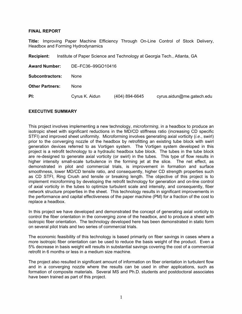
The impact on formation can be observed in the optical and beta images of the samples from the standard and the Vortigen system shown side by side in Figures II.1 and II.2, below. The advantages from improvement in formation are two fold. First, better formation gives better surface smoothness, requiring less calendering, resulting in higher caliper and less strength degradation. Second, improved formation has been shown in many studies (D. Page, 2001; Gottsching, 1979; R. Norman, 1966; and Soszynski & Seth, 1985) to improve burst and tensile strength.
3
Trials of this study have emphasized improvement in linerboad operations; however, numerous benefits also seem relevant to the production of corrugating medium, shipping sack paper and various printing and writing grades. a. Standard (sample No. 9156/01.05)2: b. Vortigen (sample No. 9156/06.04)1:
Sample from Standard tube block Sample from Vortigen system with
otherwise identical production conditions
1 For more information about the samples and other data, refer to Henssler & Bubik, 2000 [7].
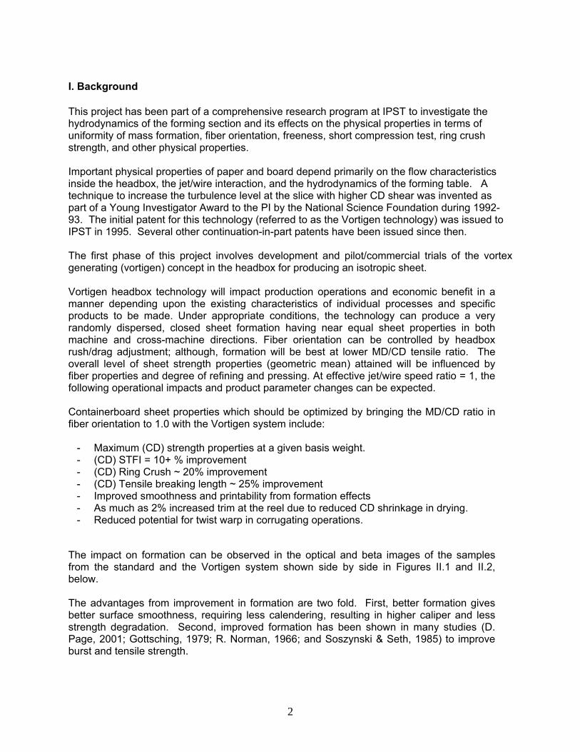
Sample from Standard Tube block Sample from Vortigen system Avg. air = 9195.2 Avg. air = 9224.2 BW= 106 g/m2 BW = 105 g/m2 standard deviation = 12.78 g/m2 standard deviation = 9.1 g/m2 coefficient of variation = 0.12 coefficient of variation =0.086
a. Standard (sample No. 9156/01.05)2: b. Vortigen (sample No. 9156/06.04)2:
Figure I.1. Optical images with transmission light
Figure I.2. High-resolution Beta formation measurements.
4
II. Project Objective The main objective of this project is to retrofit a current headbox with an on-line controlled hydrodynamic system for uniform dispersion and distribution of fibers on the moving wire. The project will proceed in three phases with the third phase requiring a new project for commercial implementation. These are:
1. generation axial vorticity in a tube bundle of the paper machine headbox to produce isotropic fiber orientation;
2. Pilot machine trials of the Vortigen concept; 3. Commercial trials of the Vortigen concept; 4. Extension of the Vortigen system to generation and control of axial vorticity in a tube
bundle using “smart materials” for on-line actuation; 5. Laboratory implementation 6. commercial implementation on a small hydraulic headbox (collaboration with a
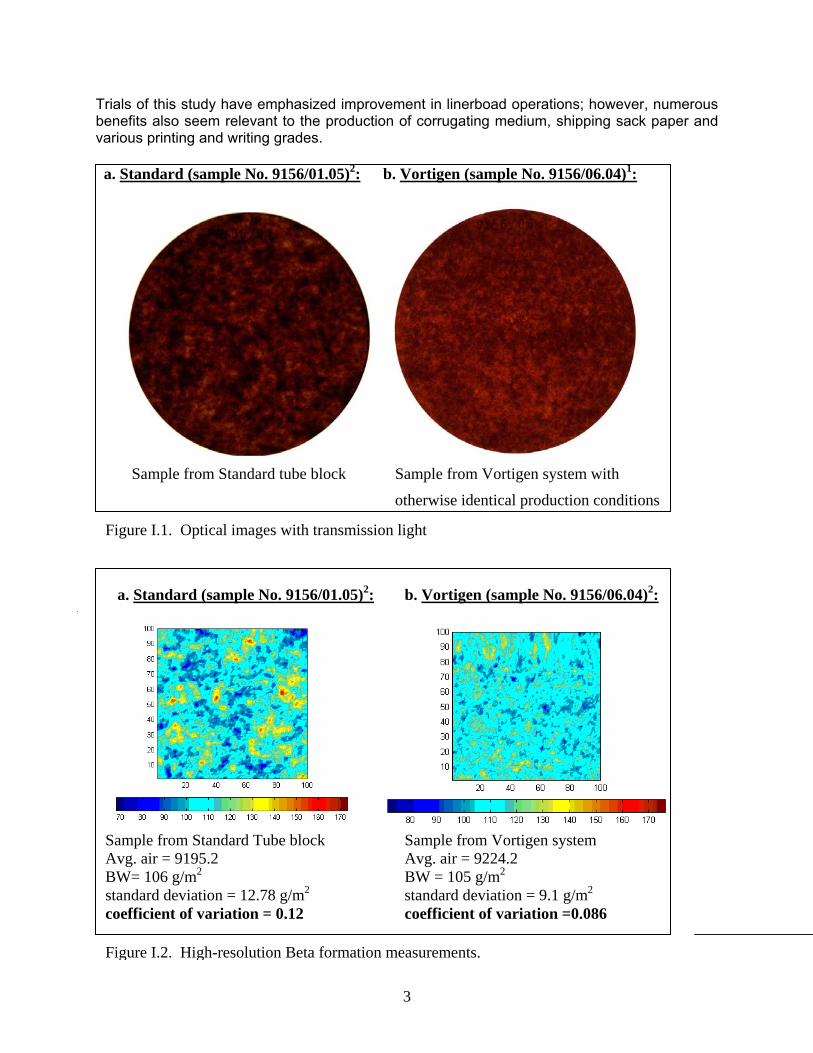
supplier and one or more paper companies through a new project) III. Introduction It is well understood that with current headbox systems, the in-plane fiber orientation and formation are coupled. That is, by increasing the convergence angle of the headbox nozzle, formation improves and fiber orientation anisotropy (i.e., MD/CD ratio approaching 1.0) increases. Consider a typical hydraulic headbox, as shown in Figure III.1. The performance of the headbox in terms of formation and fiber orientation depends primarily on the tube bank and the converging nozzle, prior to the slice. Formation and fiber orientation (F.O.) are coupled through the headbox nozzle design as outlined in Table III.I. Decreasing the convergence angle results in lower MD/CD ratio at the expense of deterioration in formation.
Figure III.1. Picture of a hydraulic headbox showing the tube bank and the converging nozzle.
Tube bank Converging nozzle
5
TABLE III.I. Impact of Headbox design on formation and fiber orientation Nozzle geometry Formation F. O. Anisotropy
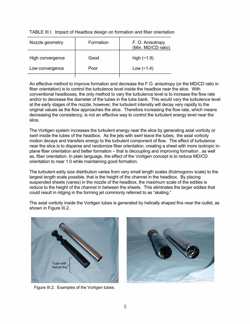
(Min. MD/CD ratio) High convergence Good high (~1.9) Low convergence Poor Low (~1.4) An effective method to improve formation and decrease the F.O. anisotropy (or the MD/CD ratio in fiber orientation) is to control the turbulence level inside the headbox near the slice. With conventional headboxes, the only method to vary the turbulence level is to increase the flow rate and/or to decrease the diameter of the tubes in the tube bank. This would vary the turbulence level at the early stages of the nozzle, however, the turbulent intensity will decay very rapidly to the original values as the flow approaches the slice. Therefore increasing the flow rate, which means decreasing the consistency, is not an effective way to control the turbulent energy level near the slice. The Vortigen system increases the turbulent energy near the slice by generating axial vorticity or swirl inside the tubes of the headbox. As the jets with swirl leave the tubes, the axial vorticity motion decays and transfers energy to the turbulent component of flow. The effect of turbulence near the slice is to disperse and randomize fiber orientation, creating a sheet with more isotropic in-plane fiber orientation and better formation – that is decoupling and improving formation , as well as, fiber orientation. In plain language, the effect of the Vortigen concept is to reduce MD/CD orientation to near 1.0 while maintaining good formation. The turbulent eddy size distribution varies from very small length scales (Kolmogorov scale) to the largest length scale possible, that is the height of the channel in the headbox. By placing suspended sheets (vanes) in the nozzle of the headbox, the maximum scale of the eddies is reduce to the height of the channel in between the sheets. This eliminates the larger eddies that could result in ridging in the forming jet commonly referred to as “skating.” The axial vorticity inside the Vortigen tubes is generated by helically shaped fins near the outlet, as shown in Figure III.2.
Figure III.2. Examples of the Vortigen tubes.
Tube with helical fins
6
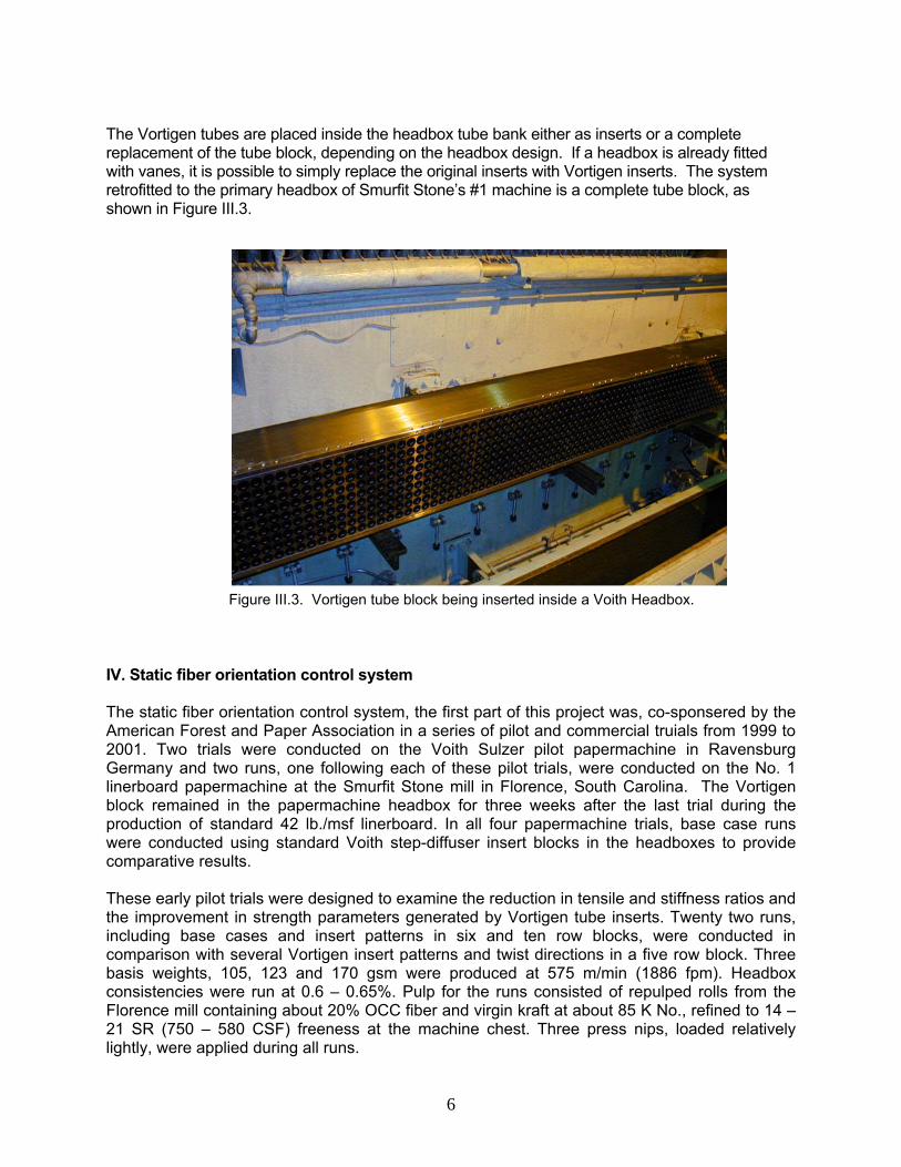
The Vortigen tubes are placed inside the headbox tube bank either as inserts or a complete replacement of the tube block, depending on the headbox design. If a headbox is already fitted with vanes, it is possible to simply replace the original inserts with Vortigen inserts. The system retrofitted to the primary headbox of Smurfit Stone’s #1 machine is a complete tube block, as shown in Figure III.3. IV. Static fiber orientation control system The static fiber orientation control system, the first part of this project was, co-sponsered by the American Forest and Paper Association in a series of pilot and commercial truials from 1999 to 2001. Two trials were conducted on the Voith Sulzer pilot papermachine in Ravensburg Germany and two runs, one following each of these pilot trials, were conducted on the No. 1 linerboard papermachine at the Smurfit Stone mill in Florence, South Carolina. The Vortigen block remained in the papermachine headbox for three weeks after the last trial during the production of standard 42 lb./msf linerboard. In all four papermachine trials, base case runs were conducted using standard Voith step-diffuser insert blocks in the headboxes to provide comparative results. These early pilot trials were designed to examine the reduction in tensile and stiffness ratios and the improvement in strength parameters generated by Vortigen tube inserts. Twenty two runs, including base cases and insert patterns in six and ten row blocks, were conducted in comparison with several Vortigen insert patterns and twist directions in a five row block. Three basis weights, 105, 123 and 170 gsm were produced at 575 m/min (1886 fpm). Headbox consistencies were run at 0.6 – 0.65%. Pulp for the runs consisted of repulped rolls from the Florence mill containing about 20% OCC fiber and virgin kraft at about 85 K No., refined to 14 – 21 SR (750 – 580 CSF) freeness at the machine chest. Three press nips, loaded relatively lightly, were applied during all runs.
Figure III.3. Vortigen tube block being inserted inside a Voith Headbox.
7
Results of the pilot trial had indicated that Vortigen inserts installed in an alternating checkerboard pattern of twist direction in a nine row block showed promise in producing the desired improvements in strength ratios and other paper properties. Base line runs were made with the standard step diffuser block at 1865 fpm on both 42 and 35 lb/msf grades at 0.52 and 0.62 % HB consistency. (It was later found that these consistencies were actually 0.72 and 0.82%). As with the pilot trials, rush/drag was adjusted in several steps from –40 through 0 to +30 fpm and samples taken on one set turn-ups. On the next day the Vortigen block was installed and the same procedure was initiated, starting with 42 lb liner. While preliminary results indicated improvement in the desired ratios and paper properties, unstable slice flows and “skating” created unsellable CD basis weight and moisture profiles. After several hours of effort by the papermakers, the trial was halted. After evaluation of the Florence experience, the pilot headbox Vortigen block was modified with a redesign of the Vortigen tube inlet flange and means for attaching Lexan sheets to the block to improve jet stability and reduce turbulent eddy size. Three initial trial runs included a standard step diffuser base case, a Vortigen checkerboard twist pattern (as in the first Florence trial), and a pattern with uniform twist in all inserts; all three with no Lexan sheets. Nine subsequent runs were made with the uniform Vortigen insert twist pattern and various combinations of sheet length and row position. Slice jet and forming table stability were evaluated subjectively, visually and by high-speed videography. All runs were at 105 gsm basis weight. Tapio instrumentation was used to conduct basis weight variance partition analysis in strip samples. Pressing level was relatively high for all runs, with two nips loaded to about 4300 pli each. Pulp consisted of butt rolls donated by Weyerhaeuser, Pine Hill containing about 20% OCC and virgin pulp at about 95 Kappa No. Pulp freeness was found to drift somewhat during these trials, causing predictable impacts on strength properties. Details of this trial may be found in a Voith Paper Trial Report (2000). This second trial series on the Florence No.1 papermachine was conducted to confirm that difficulties experienced during the first trial had been resolved (indicated by the Ravensburg II results) and that expected product property benefits could be achieved. Three runs on 35 lb./msf were conducted, including a base line run using the standard step diffuser insert block. Two trial runs using Vortigen inserts with uniform twist pattern and Lexan sheet sets at two lengths provided both very conservative and more aggressive turbulence effects. As with previous trials, a series of rush/drag levels were set for each run going from –50 to 0 to +10 fpm. It should be noted that the papermachine has three open draws between the couch and the dryers (no suction pick-up), is driven by a steam turbine lineshaft and has relatively low level pressing (no shoe press). These factors may have contributed to runnability difficulties experienced as rush/drag approached the zero point during the various runs. The machine was slowed about 100 fpm and refining was reduced during the last run in an attempt to stabilize the couch and press draws. The Vortigen block remained in the headbox for three weeks after the trial, during production of 42 lb./msf liner, and was removed during an early field day called to replace a 1st Press jack-shaft. A converting trial to compare the performance of baseline and Vortigen trial liners produced at zero rush/drag during Florence Trial II was conducted at the Smurfit Stone plant in Latta, South Carolina. During five corrugator runs at 700 – 750 fpm, rolls from the front/front and front /back papermachine positions from each trial liner were mounted at the single- and double-facer. The front/front baseline roll combination was then repeated. The 35HP/26C/35HP combined board was then processed on a rotary die-cutter and a flexo-folder-gluer, both fitted for simple black

8
printing. Liner, medium, combined board and standard test box samples were evaluated at IPST and Weyerhaeuser test facilities. Details of this trial may be found in a Project Final Report by IPST to AF&PA (Shaepe, 2001). RESULTS In reviewing trial results, it should be recognized that the Vortigen headbox technology affects only fiber orientation and distribution and that numerous other process variables also interact to affect specific physical product test levels. This point will be discussed in more detail later. For this reason it may be more appropriate to judge the technology on the basis of comparisons of strength ratios and formation values; although, CD stiffness values may be of the most interest. In addition, pilot trials can give indications of relative property changes but cannot reflect all the positive (or negative) changes to sheet properties that may affect convertability or final product functionality. Previous reports (Holzer, 1999; Henssler and Bubik, 2000) have contained voluminous tables of results. The following listing of key trial results, (compared to standard step diffuser results) while not always positive, reflect continued progress toward commercialization of the Vortigen technology: - Ravensburg Trial I
• Reduced MD/CD TSI Ratio from 1.5 to 1.0 (Sonic elastic modulus) • Improved CD STFI by 10% • Improved CD Ring Crush by 20% • Improved CD Breaking Length (Tensile) by 25% • Improved Ambertec formation by 8%
- Florence Trial I
• Effects on formation and strength properties inconclusive. • Slice jet turbulence and instability caused unacceptable variation in basis
weight and moisture profiles.
- Ravensburg Trial II
• Reduced MD/CD TSI Ratio from 1.5 to <1.0 • Improved CD SCT Index (STFI) by 30% • Improved Burst Index by 10% • Improved Ambertec formation by 30%

9
- Florence Trial II
– w/very conservative Lexan sheet lengths (longer), 35HP grade.
• No change in properties vs. standard step-diffuser headbox.
– w/ more optmimum Lexan sheet lengths (shorter), 35HP grade.
• Reduced MD/CD TSI Ratio from 1.98 to 1.69 • Reduced MD/CD STFI Ratio from 1.51 to 1.37 • Maintained STFI level at 22.6 with 12% less refining specific energy • Mullen reduced 8% because of 12% less refining • Sheffield Smoothness improved 20 – 30 units to 315 – 320 range • Basis Weight and Moisture variability in normal range • Mill experience on 42lb./msf during three weeks after trial indicated 4%
STFI average improvement with 5% less refining at –25 fpm drag. - Latta Box Plant Trial
• No difference in corrugator runnability between standard and Vortigen liners. (both very good)
• No difference in printing, folding, die-cutting, slotting. • Fiber Angle of both liners within +/- 5 deg. • Both ECT and BCT of the finished boxes declined about 3 – 5% during
the course of the converting runs, but not likely due to liner effects.
10
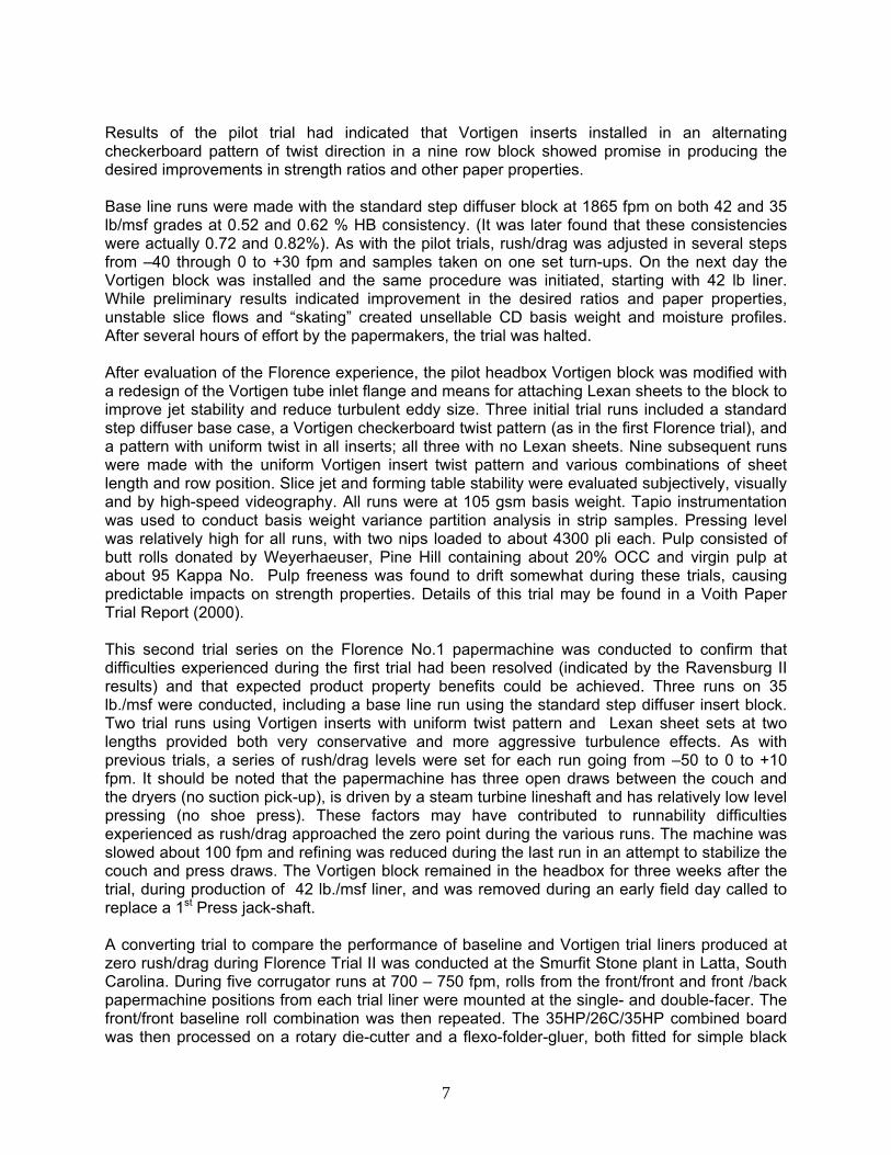
V. On-line control system A robust system has been designed for pilot trials and final commercial implementation. The system uses four thin SMA vanes spaced evenly around the circumference of the Vortigen tube that twist through a fixed angle when heated above their transition temperature Tc (Fig. V.1a) and return to an untwisted or straight configuration at temperatures below Tc (Fig. V.1b). SMA of various compositions are commercially available with transition temperatures Tc ranging from about 20°C up to 90°C. Four of these vanes will be mounted symmetrically in the Vortigen tube (Figure V.1c) and when twisted, will generate the axial vorticity or swirl required for microforming. This new Vortigen concept is more robust than the single-vane system because the vanes themselves are composed of the SMA, thereby greatly simplifying the vane actuation and swirl control systems. During this quarter, we have improved our test facility to overcome lensing effects due to the pipe curved wall. Therefore, we have assembled a rectangular tank of optical glass filled with glycerin, a liquid whose refractive index is virtually identical to that of the pipe wall, and attached this box to the curved wall of the pipe. Now, we observe a significant improvement in measurements of the azimuthal velocity with the new set-up.
Figure V.1. (a) A sketch of the SMA fin shown in its unheated, relatively soft martensite phase at a temperature below Tc. (b) The same SMA fin shown in its heated, relatively stiff austenite phase at temperatures above Tc. (c) Photo of an assembly of four such SMA fins in the new Vortigen concept.
The one-way SMA fins easily assume their “twisted” configuration when heated above their transition temperature. Returning the one-way SMA fins to their straight configuration below this temperature, however, requires an external restoring force. In two-way shape memory effect, unlike the one-way effect, an external force is not needed to achieve reversible shape change. Therefore, a component can be made to twist one way on heating and turn back to its original shape on cooling. The two-way fins used have an austenite finish temperature of approximately 100 oC, meaning that, they will have a twisted shape above this temperature. We also focused on developing a method to heat the SMA vanes for online control. Using a DC-current source, we have tested one of the SMA fins in air. DC-current is applied to the tip of the fin, which would stay outside the vortigen tube. The power requirement for changing the phase of the material from martensite to austenite is measured to be 1.4 W, which should be applied for a duration of 120 sec. It is expected that when the fins are cooled by the flow, power requirement will be higher.
11
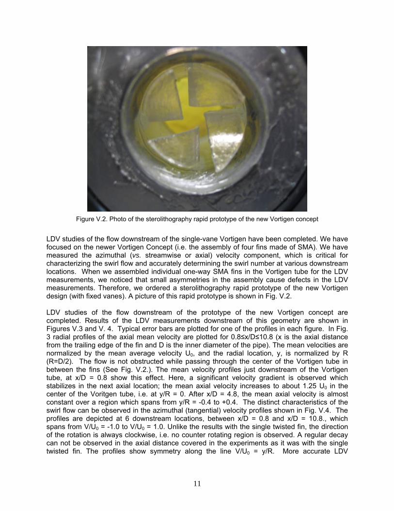
Figure V.2. Photo of the sterolithography rapid prototype of the new Vortigen concept
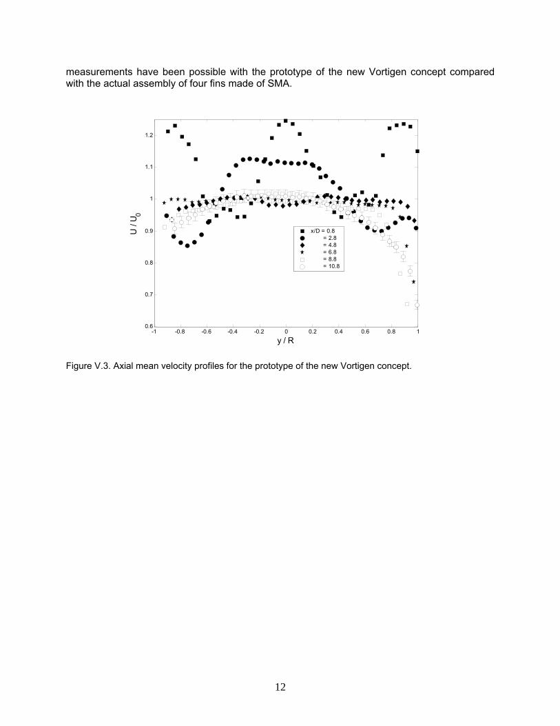
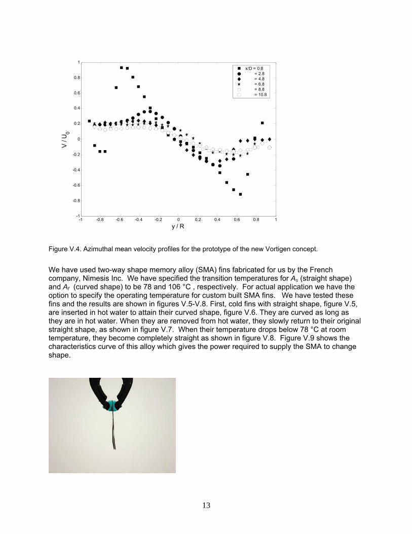
LDV studies of the flow downstream of the single-vane Vortigen have been completed. We have focused on the newer Vortigen Concept (i.e. the assembly of four fins made of SMA). We have measured the azimuthal (vs. streamwise or axial) velocity component, which is critical for characterizing the swirl flow and accurately determining the swirl number at various downstream locations. When we assembled individual one-way SMA fins in the Vortigen tube for the LDV measurements, we noticed that small asymmetries in the assembly cause defects in the LDV measurements. Therefore, we ordered a sterolithography rapid prototype of the new Vortigen design (with fixed vanes). A picture of this rapid prototype is shown in Fig. V.2. LDV studies of the flow downstream of the prototype of the new Vortigen concept are completed. Results of the LDV measurements downstream of this geometry are shown in Figures V.3 and V. 4. Typical error bars are plotted for one of the profiles in each figure. In Fig. 3 radial profiles of the axial mean velocity are plotted for 0.8≤x/D≤10.8 (x is the axial distance from the trailing edge of the fin and D is the inner diameter of the pipe). The mean velocities are normalized by the mean average velocity U0, and the radial location, y, is normalized by R (R=D/2). The flow is not obstructed while passing through the center of the Vortigen tube in between the fins (See Fig. V.2.). The mean velocity profiles just downstream of the Vortigen tube, at x/D = 0.8 show this effect. Here, a significant velocity gradient is observed which stabilizes in the next axial location; the mean axial velocity increases to about 1.25 U0 in the center of the Voritgen tube, i.e. at y/R = 0. After x/D = 4.8, the mean axial velocity is almost constant over a region which spans from y/R = -0.4 to +0.4. The distinct characteristics of the swirl flow can be observed in the azimuthal (tangential) velocity profiles shown in Fig. V.4. The profiles are depicted at 6 downstream locations, between x/D = 0.8 and x/D = 10.8., which spans from V/U0 = -1.0 to V/U0 = 1.0. Unlike the results with the single twisted fin, the direction of the rotation is always clockwise, i.e. no counter rotating region is observed. A regular decay can not be observed in the axial distance covered in the experiments as it was with the single twisted fin. The profiles show symmetry along the line V/U0 = y/R. More accurate LDV
12
measurements have been possible with the prototype of the new Vortigen concept compared with the actual assembly of four fins made of SMA.
-1 -0.8 -0.6 -0.4 -0.2 0 0.2 0.4 0.6 0.8 10.6
0.7
0.8
0.9
1
1.1
1.2
y / R
U /
U 0
x/D = 0.8 = 2.8 = 4.8 = 6.8 = 8.8 = 10.8
Figure V.3. Axial mean velocity profiles for the prototype of the new Vortigen concept.
13
-1 -0.8 -0.6 -0.4 -0.2 0 0.2 0.4 0.6 0.8 1-1
-0.8
-0.6
-0.4
-0.2
0
0.2
0.4
0.6
0.8
1
y / R
V /
U0
x/D = 0.8 = 2.8 = 4.8 = 6.8 = 8.8 = 10.8
Figure V.4. Azimuthal mean velocity profiles for the prototype of the new Vortigen concept.
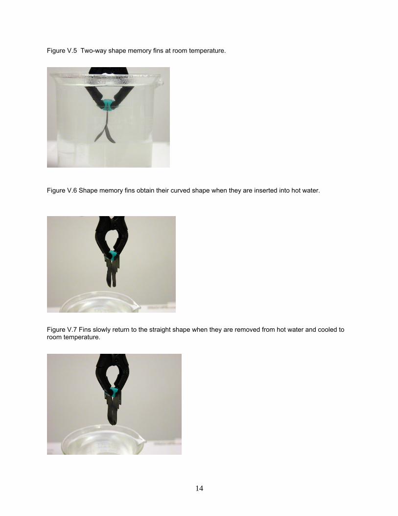
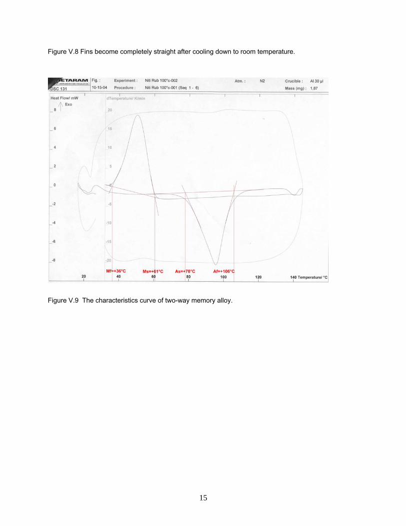
We have used two-way shape memory alloy (SMA) fins fabricated for us by the French company, Nimesis Inc. We have specified the transition temperatures for As (straight shape) and Af (curved shape) to be 78 and 106 °C , respectively. For actual application we have the option to specify the operating temperature for custom built SMA fins. We have tested these fins and the results are shown in figures V.5-V.8. First, cold fins with straight shape, figure V.5, are inserted in hot water to attain their curved shape, figure V.6. They are curved as long as they are in hot water. When they are removed from hot water, they slowly return to their original straight shape, as shown in figure V.7. When their temperature drops below 78 °C at room temperature, they become completely straight as shown in figure V.8. Figure V.9 shows the characteristics curve of this alloy which gives the power required to supply the SMA to change shape.
14
Figure V.5 Two-way shape memory fins at room temperature.
Figure V.6 Shape memory fins obtain their curved shape when they are inserted into hot water.
Figure V.7 Fins slowly return to the straight shape when they are removed from hot water and cooled to room temperature.
15
Figure V.8 Fins become completely straight after cooling down to room temperature.
Figure V.9 The characteristics curve of two-way memory alloy.
16
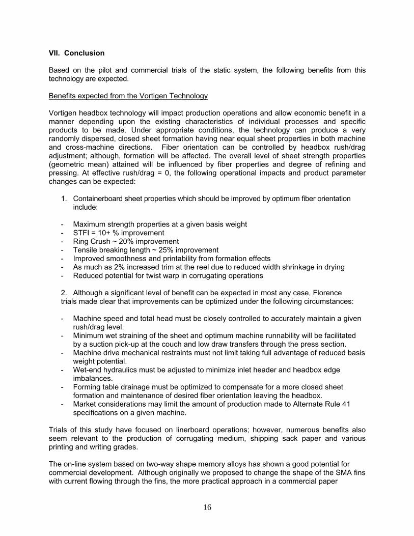
VII. Conclusion Based on the pilot and commercial trials of the static system, the following benefits from this technology are expected. Benefits expected from the Vortigen Technology Vortigen headbox technology will impact production operations and allow economic benefit in a manner depending upon the existing characteristics of individual processes and specific products to be made. Under appropriate conditions, the technology can produce a very randomly dispersed, closed sheet formation having near equal sheet properties in both machine and cross-machine directions. Fiber orientation can be controlled by headbox rush/drag adjustment; although, formation will be affected. The overall level of sheet strength properties (geometric mean) attained will be influenced by fiber properties and degree of refining and pressing. At effective rush/drag = 0, the following operational impacts and product parameter changes can be expected:
1. Containerboard sheet properties which should be improved by optimum fiber orientation include:
- Maximum strength properties at a given basis weight - STFI = 10+ % improvement - Ring Crush ~ 20% improvement - Tensile breaking length ~ 25% improvement - Improved smoothness and printability from formation effects - As much as 2% increased trim at the reel due to reduced width shrinkage in drying - Reduced potential for twist warp in corrugating operations
2. Although a significant level of benefit can be expected in most any case, Florence trials made clear that improvements can be optimized under the following circumstances: - Machine speed and total head must be closely controlled to accurately maintain a given
rush/drag level. - Minimum wet straining of the sheet and optimum machine runnability will be facilitated
by a suction pick-up at the couch and low draw transfers through the press section. - Machine drive mechanical restraints must not limit taking full advantage of reduced basis
weight potential. - Wet-end hydraulics must be adjusted to minimize inlet header and headbox edge
imbalances. - Forming table drainage must be optimized to compensate for a more closed sheet
formation and maintenance of desired fiber orientation leaving the headbox. - Market considerations may limit the amount of production made to Alternate Rule 41
specifications on a given machine. Trials of this study have focused on linerboard operations; however, numerous benefits also seem relevant to the production of corrugating medium, shipping sack paper and various printing and writing grades. The on-line system based on two-way shape memory alloys has shown a good potential for commercial development. Although originally we proposed to change the shape of the SMA fins with current flowing through the fins, the more practical approach in a commercial paper

17
machine is to change the temperature of the stock for on-line control of the the vortigen effect. In other words, the shape of the SMA fin will automatically be controlled by the stock temperature. With this approacvh, the installation of the on-line system will be as easy as the static vortigen system which has been demonstrated in a commercial machine. We are hoping that we can commercialize this technology through a new project with participation of a machine supplier and one or more paper companies.
18
VIII. Publications resulting from this project
– Cazan, R., and Aidun, CK, “Experimental investigation of the swirling flow induced by a twisted tape inside a circuler pipe,” to be submitted to Phys of Fluids, 2007.
– Parsheh, M., Aidun, C.K., “Counter-rotating core in swirling turbulent flow inside a pipe,” Phys of
Fluids, Vol. 19, No. 6, 2007. – Parsheh M., Brown, M., and Aidun, C.K., “Fiber Orientation in a Planar Contraction: Shape
Effect” Int. J. Multiphase Flow, 32, 1354-1369, 2006. – Brown, M., Parsheh, M., and Aidun, C.K., “Turbulent Flow in a Converging Channel: Effect of
Contraction and Return to Isotropy,” J. Fluid Mech., 560, 437-448, 2006.
– Parsheh, M., Brown, M. and Aidun, C.K., “Investigation of Closure Approximations for Fiber Orientation Distribution in Contracting Turbulent Flow,” J. Non-Newtonian Fluid Mechanics, 136, 38-49, 2006.
– Parsheh, M., Brown, M. and Aidun, C.K., “On the Orientation of Stiff Fibres Suspended in
Turbulent Flow in a Planar Contraction,” J. Fluid Mech., 545, 245-269, 2005. – Xu, Hanjiang (John), and Aidun, C.K., “Characteristics of Fiber Suspension Flow in a
Rectangular Channel” Int. J. Multiphase Flow, 3 1/3, pp. 318-336, 2005.
– Ono, K., Xu, H., Park, C., Yoda, M, and Aidun, C., “Forming Jet Surface Velocity Profile Measurements with High Speed Digital Imaging,” Tappi J., 84 (3), 2001. (2002 Tappi J. and J. Pulp and Paper Sci. best research paper award)
– Kondo, Y., and Aidun, C.K., “Development of image analysis for the measurement of
internal properties of coated paper by X-ray microtomography,” Tappi Coating Conf., 2005.
– Aidun, C.K., “fiber orientation in headbox and forming jet -- from modeling to 3-D
imaging,” Tappi Paper making Conf., Milwaukee, Wisconsin, 2005. – Parsheh, M., Brown, M.L., Aidun, C.K., “On the development of the rotational diffusion in
a planar contraction”, 57th Annual Meeting, Div. Fluid Dynamics, American Physical Society, Nov. 23-25, 2004.
Patents (Inventor: Aidun, C.K.)
Aidun, C.K. “Method and Apparatus to Enhance Paper Forming,” – Patent no. 5,792,321, issued Aug. 11, 1998; – CIP Pat. no. 5,876,564 issued March 2, 1999; – CIP Pat. no. 6,153,057 issued Nov. 28, 2000; – CIP Pat. no. 6,368,460 issued April 9, 2002.

19
REFERENCES 1. Page, D. H., personal communication, March 8, 2001. 2. Gottsching, L., Wochenblatt fur Paperfabrikation 107 (7): 228, 1979. 3. Norman, R. J., Consolidation of the Paper Web (F. Bolam, Ed.), Vol. 1, Tech. Sect., BPBMA,
London, pp. 269 – 298, 1966. 4. Soszynski, R.M., and Seth, R.S., International Packaging Conference Proceedings, Vol. 2,
Beijing, China, pp. 590 – 604, 1985. 5. Industial Energy End-Use Analysis and Conservation Potential in Six Major Industries in
Canada, M.J. Jaccard and Assoc., Willis Energy Services, Ltd., March, 1996. 6. Holzer, W., “Vortigen Tubes – Headbox for High CD Strength”, Trial No. 8410, Report No.
1099, Voith Sulzer Paper Technology, Ravensburg, Germany, December 16, 1999. 7. Henssler, J., and Bubik, A., “Vortigen II”, Trial No. 9156, Report No. 1117, Voith Paper,
Ravensburg, Germany, October 10, 2000. 8. Mann, R.W., Baum, G.A., and Habeger, C.C., Tappi J., 63 (2), 163, 1980. 9. Fleischman, E.H., Baum, G.A., and Habeger, C.C., Tappi J., 65 (10), 115, 1982. 10. Jonakin, J.L., Aidun, C., Kast, T., Pantaleo, S., Replogle, J., “Pilot Headbox Trial of Vortigen Technology”, Report To American Forest and Paper Association Containerboard Group, Project 3813, Camden, Alabama, pp. 1 – 12, 2000. 11. Schaepe, M., Final Report by IPST to AF&PA Containerboard Group on Project 4270 (in
preparation) 2001.
20
APPENDIX I (to be submitted to Phys Fluids for publication)
Experimental investigation of the swirling flow induced by Vortigen tube This section describes the experimental investigation of the turbulent swirling flow induced by the vortigen tube. This work was done wit my student, Radu Cazan who has done the experiments and provided all of the data in this section. The origin of this work is from the observations of the Vortigen experiments in the pilot machine at Ravensburg, Germany and the commercial trials at the Florence Paper Mill at Florence SC. These experiments showed that at high speed vortices appear superimposed on the forming jet. Subsequent to these trials, we continued with laboratory experiments where a single vortigen tube was installed inside a tube and the the flow downstream was analyzed in some detail. The investigation shows the existence of two co-rotating helical vortices superimposed over the main swirling flow. The close proximity of the two co-rotating vortices creates flow reversal at the central region of the pipe. In order to understand the source of this problem, more detailed studies was undertaken. The flow is investigated using detailed LDV measurements and high speed visualization with air bubbles. Three cases with twisted fins having 45, 60 and 90 mm pitches are investigated at Reynolds number ranging from 25,000 to 100,000. Through a reconstruction technique, the tangential flow field for a twisted fin with 60 mm pitch is described by 400 measurements in the axial direction, providing accuracy similar to the one achieved in numerical simulations. The measurements are confirmed by direct visualization of fine air bubbles injected in the flow. Images and movies recorded with a high speed camera clearly show that the secondary co-rotating helical vortices are very stable as they rotate around their own axis. After extracting the defining azimuthal velocity profiles of the main vortex and of the two secondary vortices, it is observed that the maximum azimuthal velocity of all three normalized with the bulk velocity is about the same. The pitch of the helical vortices is found to be 4/3 of the pitch of the twisted fin for all three swirlers investigated, independent of the Reynolds number for the range considered. We conclude that the co-rotating helical vortices are generated inside the twisted fin swirler, as predicted in the previous study of this flow. It appears that the main rotational flow accelerates the co-rotating vortex while it decelerates the counter-rotating vortex. As a result, the counter-rotating vortex disappears while the co-rotating vortices reach the same maximum azimuthal velocity as the main flow. Thus the azimuthal velocity at the wall is approximately doubled in the region where the secondary helical vortices are superimposed on the main rotating flow.
21
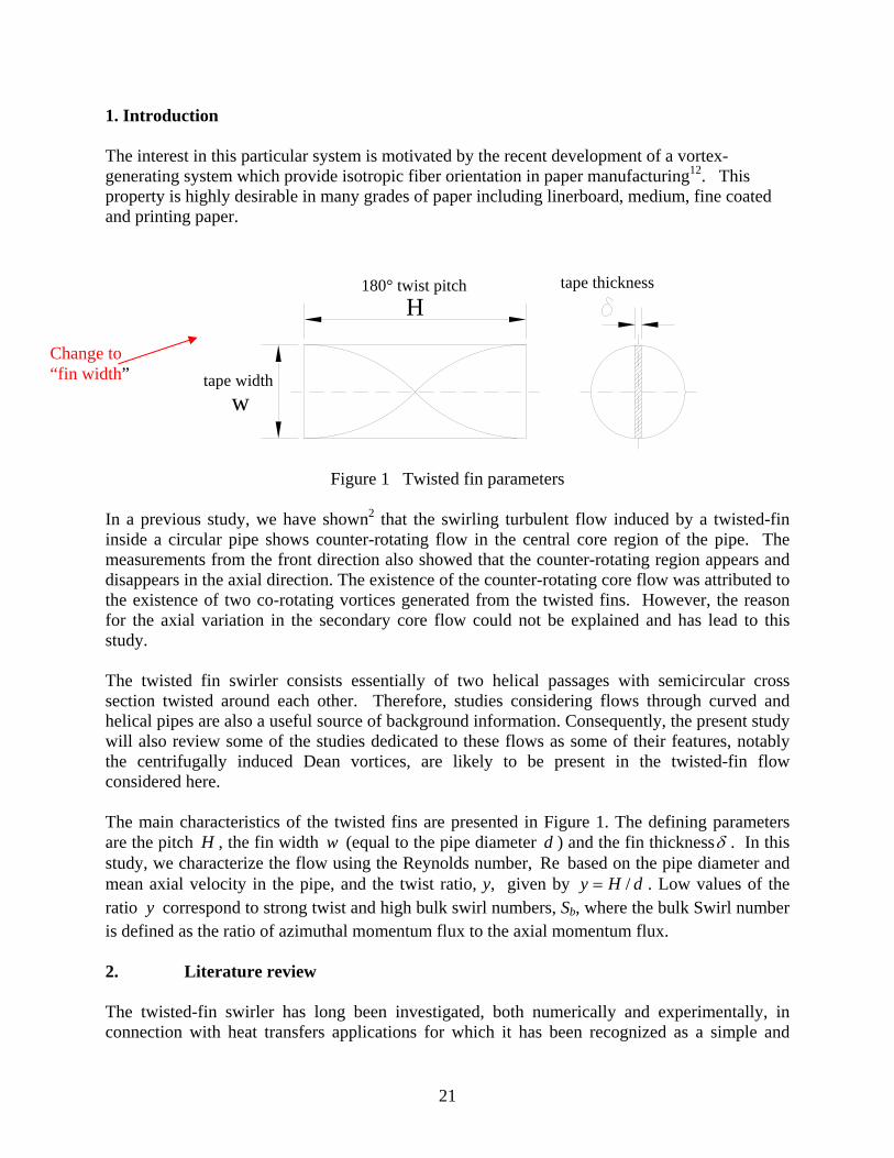
1. Introduction The interest in this particular system is motivated by the recent development of a vortex-generating system which provide isotropic fiber orientation in paper manufacturing12. This property is highly desirable in many grades of paper including linerboard, medium, fine coated and printing paper.
Figure 1 Twisted fin parameters In a previous study, we have shown2 that the swirling turbulent flow induced by a twisted-fin inside a circular pipe shows counter-rotating flow in the central core region of the pipe. The measurements from the front direction also showed that the counter-rotating region appears and disappears in the axial direction. The existence of the counter-rotating core flow was attributed to the existence of two co-rotating vortices generated from the twisted fins. However, the reason for the axial variation in the secondary core flow could not be explained and has lead to this study. The twisted fin swirler consists essentially of two helical passages with semicircular cross section twisted around each other. Therefore, studies considering flows through curved and helical pipes are also a useful source of background information. Consequently, the present study will also review some of the studies dedicated to these flows as some of their features, notably the centrifugally induced Dean vortices, are likely to be present in the twisted-fin flow considered here. The main characteristics of the twisted fins are presented in Figure 1. The defining parameters are the pitch H , the fin width w (equal to the pipe diameter d ) and the fin thicknessδ . In this study, we characterize the flow using the Reynolds number, Re based on the pipe diameter and mean axial velocity in the pipe, and the twist ratio, y, given by dHy /= . Low values of the ratio y correspond to strong twist and high bulk swirl numbers, Sb, where the bulk Swirl number is defined as the ratio of azimuthal momentum flux to the axial momentum flux. 2. Literature review The twisted-fin swirler has long been investigated, both numerically and experimentally, in connection with heat transfers applications for which it has been recognized as a simple and
180° twist pitchH
tape width w
tape thickness
Change to “fin width”
22
cheap mean to produce significant heat transfer enhancement1. Unfortunately most studies investigated only the heat transfer and friction coefficient variations without any attempts to elucidate the mechanisms behind these changes. The following review will try to summarize the few articles which do investigate the fluid mechanics details of these flows. One of the first studies of twisted fin flows studied examined the decay of turbulent swirling water flow in a 1 inch diameter pipe with a twisted fin15. The twisted fin was long enough to consider the flow fully developed. The swirl measured at different axial locations using a rotating blade in the middle of the pipe decayed to 10-20% of the initial swirl intensity in about 50 diameters. The swirl decay was faster at low Reynolds numbers and independent of the pitch. Seymour23 investigating high Reynolds number swirling flows in pipes showed the presence of two asymmetric vortices in the flow field at Re=100,000 in a 3 inch pipe. Measurements near the walls of the pipe and near the twisted fins revealed a pressure gradient in the direction of the twist. A study on twisted fin inserts by Smithberg & Landis showed similar features as Seymour’s investigation for axial velocities, but no secondary flow patterns for tangential velocities. Later, Date5 investigated numerically the flow in the laminar regime confirming the presence of two vortices in the semicircular cross section for low Reynolds numbers. He showed axial velocity profiles exhibiting an evident asymmetry. At low twist ratios the peak values occurred near the wall, in opposite direction relative to the twist of the fin. At higher twist ratios the velocity profiles showed two peaks. More recent studies17,18,19 have identified the secondary flow as one of the important causes of the heat transfer enhancement in swirling flows. In these studies, smoke visualization in air was used at low Reynolds numbers to validate numerical simulations. The images showed the presence of two vortices in the semicircular cross section. The two vortex cell pattern emerged when the Reynolds number was increased or the twist ratio was decreased. Kazushia et al.,14 described another numerical investigation of the laminar swirling flow generated by a twisted-fin insert in a cylindrical pipe. Their simulation captured the inception and evolution of the secondary flow showing that the secondary flow first appears early after the inlet in a central position and then drifts to the corner of the semicircle domain, against the twist direction. This drifting was explained as an effect of the centrifugal forces, but the exact mechanism is not given. They assumed that the buoyancy effect is important only for the laminar regime subject to high heat flux and not for turbulent flows. They concluded that when the buoyancy is neglected, the flow patterns depend only on the swirl number and not on the Reynolds number. A class of flows with similar characteristics to the twisted fin flows are the flows through helical pipes. Kao13 demonstrated that increasing the torsion magnitude at low Dean numbers might reduce the two cell secondary flow to a single vortex. His numerical simulations using the orthogonal coordinate transformation developed earlier by Germano10 showed that small changes in torsion caused significant changes in the flow pattern. The changes were more dramatic as the Dean number increased. He found that the flow patterns were influenced by the ratio torsion/curvature, rather then the absolute values of the two parameters. Testing the effect of the ratio, he found that for a ratio of 3 the lower vortex is so dominant that the upper one is squeezed
23
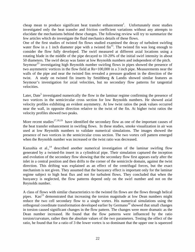
in a very narrow region with a poorly defined core. The axial velocity distribution was also shifted toward exterior at an angle. Liu & Masliyah16 who also studied numerically the laminar flow in helical pipes with circular cross section confirmed these findings. For constant Reynolds and Dean numbers the two-cell vortex pattern changed to one vortex as a result of increased torsion. As torsion increased, the maximum axial velocity location moved spirally from the outer wall toward the center while the pressure plots showed a low-pressure zone near the inner wall. 3. Experimental Setup The experimental setup is designed to allow the investigation of the swirling flow induced by a twisted fin in a circular pipe (Fig. 2). It consists of a closed circuit where water from the tanks is pumped by a 0.5 HP magnetic drive centrifugal pump with a frequency controlled motor. The inner diameter of the testing pipe is 1” ( 4.25=d mm) and the pipe is made of 1.5 mm thick glass which provides optical access. The pump allows tests at Reynolds numbers in the range 104 to 105 (Re based on the pipe diameter d ). The water tanks 1 and 2 have a maximum combined capacity of approximately 1 cubic meter but usually about half of this capacity is used during
tests. Figure 2 Setup Schematic
The flow circuit has a calming section right before the twisted fin. The calming section is designed to reduce the turbulence level9 and consists of a coarse screen, a honeycomb, two fine screens and a nozzle. The hexagonal cells of the honeycomb have a flat side to flat side dimension of 6.35 mm and wall thickness of 0.25mm. The coarse screen and the two fine screens have square cells with cell sizes 9.6, 2 and 1 mm. A nozzle with a 9:1 area contraction ratio is installed 25 mm downstream of the second fine screen. The flow exits from the nozzle into the pipe containing the twisted fin that generates swirling flow. The twisted fins tested have lengths of 45, 60 and 90 mm and a twist of °180 (the pitch is equal to the length) with corresponding pitch to diameter ratios 1.77, 2.36 and 3.54. The swirlers were manufactured by stereolithography (Vistatek Inc) using “Somos Watershed 11120” resin. The fin
LightSources
High SpeedCamera3800 fps
Air BubblesGenerator
TwistedFin
750WCompressed
Air
500W
Pump
WaterTank 1
WaterTank 2
LDVLaser Head
Glass PipeI.D. Ø1"
Glass Rectangular Container
CalmingSection
24
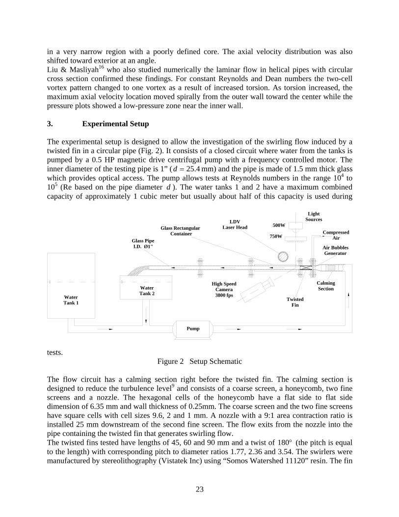
and the pipe form a single part so the width of the fin is equal to the inner diameter of the pipe, avoiding any secondary effects of the fin/wall clearance which occur in common twisted fins inserts. (Fig. 3).
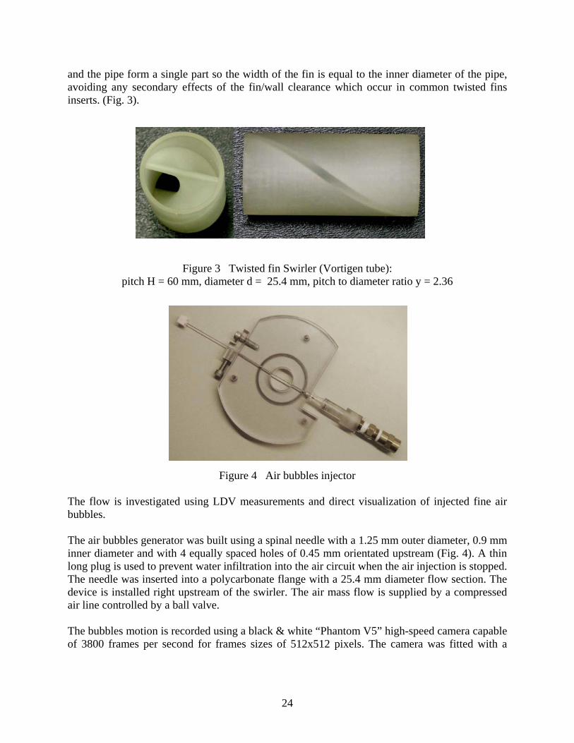
Figure 3 Twisted fin Swirler (Vortigen tube): pitch H = 60 mm, diameter d = 25.4 mm, pitch to diameter ratio y = 2.36
Figure 4 Air bubbles injector The flow is investigated using LDV measurements and direct visualization of injected fine air bubbles. The air bubbles generator was built using a spinal needle with a 1.25 mm outer diameter, 0.9 mm inner diameter and with 4 equally spaced holes of 0.45 mm orientated upstream (Fig. 4). A thin long plug is used to prevent water infiltration into the air circuit when the air injection is stopped. The needle was inserted into a polycarbonate flange with a 25.4 mm diameter flow section. The device is installed right upstream of the swirler. The air mass flow is supplied by a compressed air line controlled by a ball valve. The bubbles motion is recorded using a black & white “Phantom V5” high-speed camera capable of 3800 frames per second for frames sizes of 512x512 pixels. The camera was fitted with a
25
Nikon “Micro-Nikkor” lens with focal length 55=f mm while the lighting is provided by two light sources of 500 W and 750 W. In addition to the high speed camera some images were also recorded with a regular camera Sony DSC-H5. Flow velocities are measured using a two-component LDV system (TSI Inc.) in backscattering mode with an argon-ion laser (Coherent Innova 70). The laser has a maximum power of 3.4 W. Green light 514.5 nm was used for axial velocity measurements while blue light 488 nm was used for the azimuthal velocity measurements. One of the blue light beams had a phase shift of 1 MHz to distinguish between the positive and negative velocities. The head of the laser can be translated in all three directions using a traverse system with three electric motors controlled by a computer. The spatial resolution of the traverse is 210− mm. Velocity statistics were calculated from batches of 5000 samples collected at each measurement point. The high curvature of the pipe walls required special measures to compensate for light refraction. Following previous investigations11 on the lensing effect of curved glass walls, a rectangular glass enclosure (340x40x50 mm) with 3 mm thick walls was attached to the glass pipe, while the space between the straight walls and the pipe was filled with glycerin which has a refraction index close to the refraction index of glass. The positions and the velocities measured were than adjusted to account for the refraction changes after solving a non-linear equation system detailed by Glover & all11. Velocities were measured only along the horizontal diameter where the azimuthal velocity is equal to the vertical component of the velocity which can be measured by the LDV system. Also, measurements along the horizontal diameter minimize the light distortion created by refraction effects. The level of light distortion is still very high even with the presence of the rectangular container filled with glycerin. The 24 mm field investigated inside the pipe corresponds to only 15 mm outside the pipe (laser head motion) making the calculation of the actual positions and velocities essential for accurate measurements. The flow was seeded with 3 microns diameter titanium dioxide (TiO2) particles with density 4.2 g/cc and refraction index 2.6. Initial measurements for the 90 mm swirler were performed using 0.3 microns alumina particles (Al2O3) with density 3.84 g/cc and refraction index 1.67, but the increase in the diameter and refraction index greatly improved the signal to noise ratio (SNR) without any loss of sensitivity20. As a result, the measurements with TiO2 particles were collected much faster and they showed no scattering. The laser was also used to create a cross section sheet of light after crossing a green light beam through a divergent cylindrical lens with a focal length 40−=f mm. The laser sheet combined with the air bubbles clearly showed the cross section locations of the centers of the secondary vortices. 4. Results and Comments
26
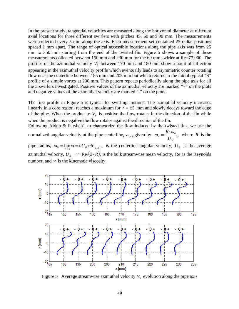
In the present study, tangential velocities are measured along the horizontal diameter at different axial locations for three different swirlers with pitches 45, 60 and 90 mm. The measurements were collected every 5 mm along the axis. Each measurement set contained 25 radial positions spaced 1 mm apart. The range of optical accessible locations along the pipe axis was from 25 mm to 350 mm starting from the end of the twisted fin. Figure 5 shows a sample of these measurements collected between 150 mm and 230 mm for the 60 mm swirler at Re=77,000. The profiles of the azimuthal velocity θV between 170 mm and 180 mm show a point of inflection appearing in the azimuthal velocity profile which eventually leads to asymmetric counter rotating flow near the centerline between 185 mm and 205 mm but which returns to the initial typical “S” profile of a simple vortex at 230 mm. This pattern repeats periodically along the pipe axis for all the 3 swirlers investigated. Positive values of the azimuthal velocity are marked “+” on the plots and negative values of the azimuthal velocity are marked “-” on the plots. The first profile in Figure 5 is typical for swirling motions. The azimuthal velocity increases linearly in a core region, reaches a maximum for 5±=r mm and slowly decays toward the edge of the pipe. When the product θVr ⋅ is positive the flow rotates in the direction of the fin while when the product is negative the flow rotates against the direction of the fin. Following Aidun & Parsheh2, to characterize the flow induced by the twisted fins, we use the
normalized angular velocity at the pipe centerline, nω , given by b
n UR 0ω
ω⋅
= , where R is the
pipe radius, 000 lim
=→∂∂==
rrrUθωω , is the centerline angular velocity, θU is the average
azimuthal velocity, ( )RU b ⋅⋅= 2Reν , is the bulk streamwise mean velocity, Re is the Reynolds number, and ν is the kinematic viscosity.
Figure 5 Average streamwise azimuthal velocity θV evolution along the pipe axis
27
between z = 150 mm and z = 230 mm
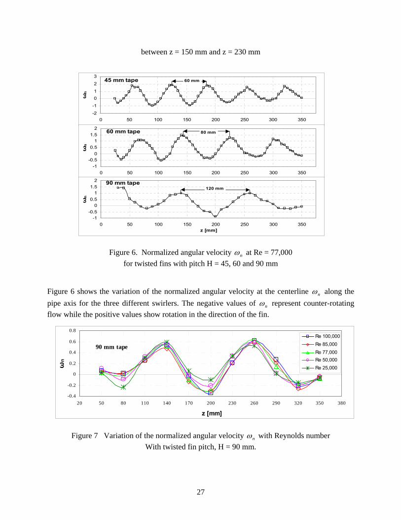
Figure 6. Normalized angular velocity nω at Re = 77,000
for twisted fins with pitch H = 45, 60 and 90 mm Figure 6 shows the variation of the normalized angular velocity at the centerline nω along the pipe axis for the three different swirlers. The negative values of nω represent counter-rotating flow while the positive values show rotation in the direction of the fin.
Figure 7 Variation of the normalized angular velocity nω with Reynolds number
With twisted fin pitch, H = 90 mm.
-2
-1
01
2
3
0 50 100 150 200 250 300 350
ωn
45 mm tape 60 mm
-1-0.5
00.5
11.5
2
0 50 100 150 200 250 300 350
ωn
60 mm tape 80 mm
-1-0.5
00.5
11.5
2
0 50 100 150 200 250 300 350z [mm]
ωn
90 mm tape120 mm
90 mm tape
-0.4
-0.2
0
0.2
0.4
0.6
0.8
20 50 80 110 140 170 200 230 260 290 320 350 380
z [mm]
ωn
Re 100,000Re 85,000Re 77,000Re 50,000Re 25,000
28
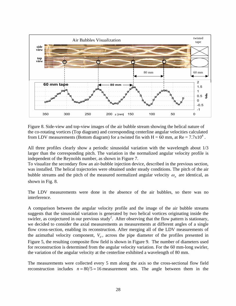
Figure 8. Side-view and top-view images of the air bubble stream showing the helical nature of the co-rotating vortices (Top diagram) and corresponding centerline angular velocities calculated from LDV measurements (Bottom diagram) for a twisted fin with H = 60 mm, at Re = 7.7x10⁴ .
All three profiles clearly show a periodic sinusoidal variation with the wavelength about 1/3 larger than the corresponding pitch. The variation in the normalized angular velocity profile is independent of the Reynolds number, as shown in Figure 7. To visualize the secondary flow an air-bubble injection device, described in the previous section, was installed. The helical trajectories were obtained under steady conditions. The pitch of the air bubble streams and the pitch of the measured normalized angular velocity nω are identical, as shown in Fig. 8. The LDV measurements were done in the absence of the air bubbles, so there was no interference. A comparison between the angular velocity profile and the image of the air bubble streams suggests that the sinusoidal variation is generated by two helical vortices originating inside the swirler, as conjectured in our previous study2. After observing that the flow pattern is stationary, we decided to consider the axial measurements as measurements at different angles of a single flow cross-section, enabling its reconstruction. After merging all of the LDV measurements of the azimuthal velocity component, θV , across the pipe diameter of the profiles presented in Figure 5, the resulting composite flow field is shown in Figure 9. The number of diameters used for reconstruction is determined from the angular velocity variation. For the 60 mm-long swirler, the variation of the angular velocity at the centerline exhibited a wavelength of 80 mm. The measurements were collected every 5 mm along the axis so the cross-sectional flow field reconstruction includes 16580 ==n measurement sets. The angle between them in the
-1-0.500.511.52
050100150200250300350 z [mm]
ωn
60 mm tape 80 mm
60 mm80 mm
twistedtape
sideview
topview
Air Bubbles Visualization
29
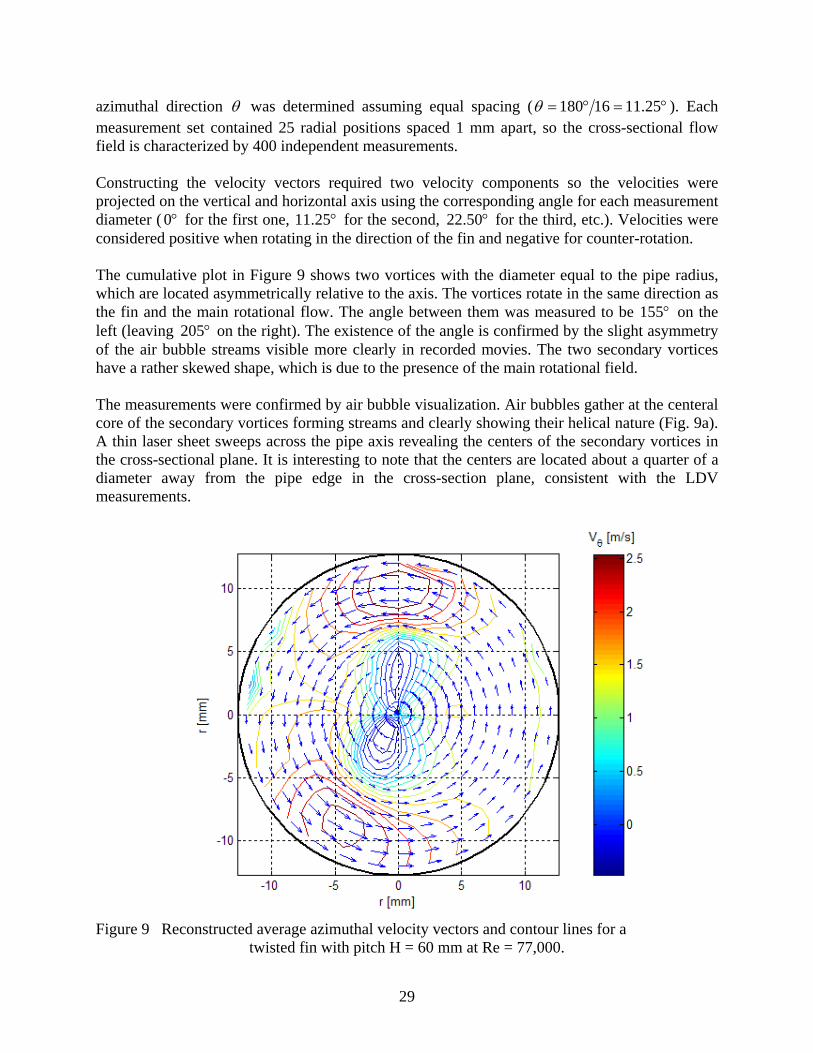
azimuthal direction θ was determined assuming equal spacing ( °=°= 25.1116180θ ). Each measurement set contained 25 radial positions spaced 1 mm apart, so the cross-sectional flow field is characterized by 400 independent measurements. Constructing the velocity vectors required two velocity components so the velocities were projected on the vertical and horizontal axis using the corresponding angle for each measurement diameter ( °0 for the first one, °25.11 for the second, °50.22 for the third, etc.). Velocities were considered positive when rotating in the direction of the fin and negative for counter-rotation. The cumulative plot in Figure 9 shows two vortices with the diameter equal to the pipe radius, which are located asymmetrically relative to the axis. The vortices rotate in the same direction as the fin and the main rotational flow. The angle between them was measured to be °155 on the left (leaving °205 on the right). The existence of the angle is confirmed by the slight asymmetry of the air bubble streams visible more clearly in recorded movies. The two secondary vortices have a rather skewed shape, which is due to the presence of the main rotational field. The measurements were confirmed by air bubble visualization. Air bubbles gather at the centeral core of the secondary vortices forming streams and clearly showing their helical nature (Fig. 9a). A thin laser sheet sweeps across the pipe axis revealing the centers of the secondary vortices in the cross-sectional plane. It is interesting to note that the centers are located about a quarter of a diameter away from the pipe edge in the cross-section plane, consistent with the LDV measurements.
Figure 9 Reconstructed average azimuthal velocity vectors and contour lines for a twisted fin with pitch H = 60 mm at Re = 77,000.
30
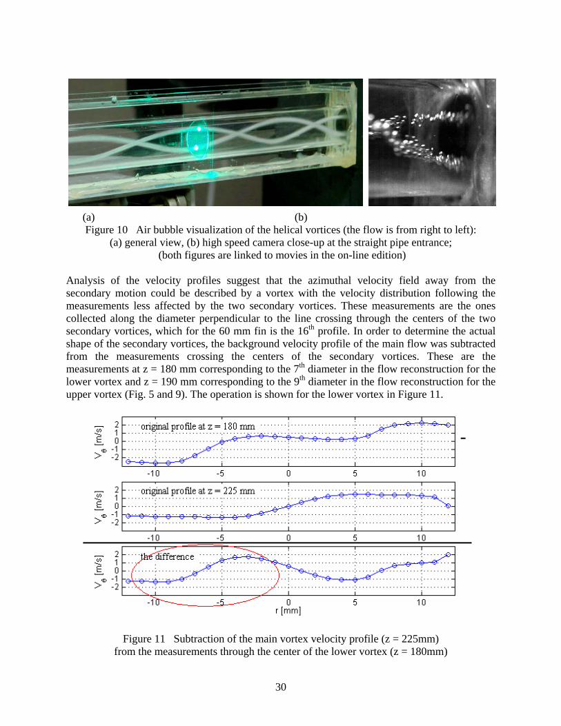
(a) (b) Figure 10 Air bubble visualization of the helical vortices (the flow is from right to left):
(a) general view, (b) high speed camera close-up at the straight pipe entrance; (both figures are linked to movies in the on-line edition)
Analysis of the velocity profiles suggest that the azimuthal velocity field away from the secondary motion could be described by a vortex with the velocity distribution following the measurements less affected by the two secondary vortices. These measurements are the ones collected along the diameter perpendicular to the line crossing through the centers of the two secondary vortices, which for the 60 mm fin is the 16th profile. In order to determine the actual shape of the secondary vortices, the background velocity profile of the main flow was subtracted from the measurements crossing the centers of the secondary vortices. These are the measurements at z = 180 mm corresponding to the 7th diameter in the flow reconstruction for the lower vortex and z = 190 mm corresponding to the 9th diameter in the flow reconstruction for the upper vortex (Fig. 5 and 9). The operation is shown for the lower vortex in Figure 11.
Figure 11 Subtraction of the main vortex velocity profile (z = 225mm) from the measurements through the center of the lower vortex (z = 180mm)
31
revealed the actual shape and magnitude of the lower secondary vortex
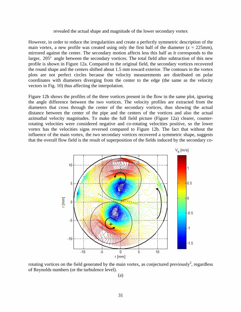
However, in order to reduce the irregularities and create a perfectly symmetric description of the main vortex, a new profile was created using only the first half of the diameter (z = 225mm), mirrored against the center. The secondary motion affects less this half as it corresponds to the larger, °205 angle between the secondary vortices. The total field after subtraction of this new profile is shown in Figure 12a. Compared to the original field, the secondary vortices recovered the round shape and the centers shifted about 1.5 mm toward exterior. The contours in the vortex plots are not perfect circles because the velocity measurements are distributed on polar coordinates with diameters diverging from the center to the edge (the same as the velocity vectors in Fig. 10) thus affecting the interpolation. Figure 12b shows the profiles of the three vortices present in the flow in the same plot, ignoring the angle difference between the two vortices. The velocity profiles are extracted from the diameters that cross through the center of the secondary vortices, thus showing the actual distance between the center of the pipe and the centers of the vortices and also the actual azimuthal velocity magnitudes. To make the full field picture (Figure 12a) clearer, counter-rotating velocities were considered negative and co-rotating velocities positive, so the lower vortex has the velocities signs reversed compared to Figure 12b. The fact that without the influence of the main vortex, the two secondary vortices recovered a symmetric shape, suggests that the overall flow field is the result of superposition of the fields induced by the secondary co-
rotating vortices on the field generated by the main vortex, as conjectured previously2, regardless of Reynolds numbers (or the turbulence level).
(a)
+
+
32
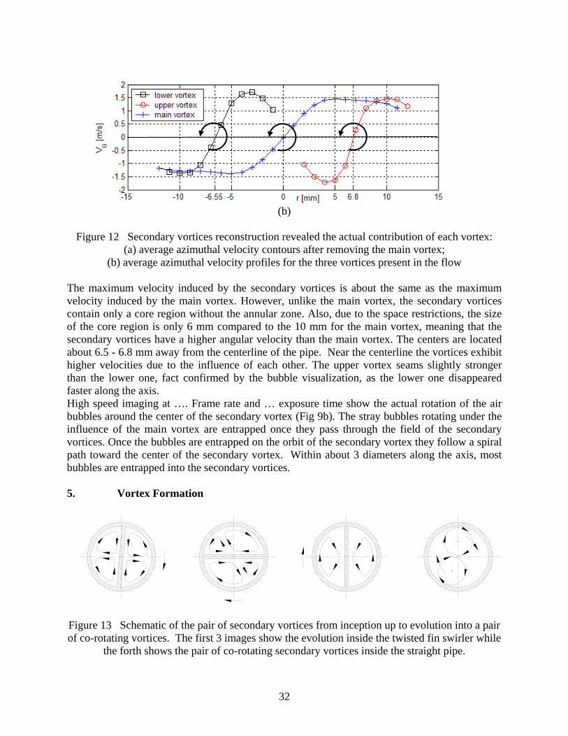
(b)
Figure 12 Secondary vortices reconstruction revealed the actual contribution of each vortex: (a) average azimuthal velocity contours after removing the main vortex;
(b) average azimuthal velocity profiles for the three vortices present in the flow The maximum velocity induced by the secondary vortices is about the same as the maximum velocity induced by the main vortex. However, unlike the main vortex, the secondary vortices contain only a core region without the annular zone. Also, due to the space restrictions, the size of the core region is only 6 mm compared to the 10 mm for the main vortex, meaning that the secondary vortices have a higher angular velocity than the main vortex. The centers are located about 6.5 - 6.8 mm away from the centerline of the pipe. Near the centerline the vortices exhibit higher velocities due to the influence of each other. The upper vortex seams slightly stronger than the lower one, fact confirmed by the bubble visualization, as the lower one disappeared faster along the axis. High speed imaging at …. Frame rate and … exposure time show the actual rotation of the air bubbles around the center of the secondary vortex (Fig 9b). The stray bubbles rotating under the influence of the main vortex are entrapped once they pass through the field of the secondary vortices. Once the bubbles are entrapped on the orbit of the secondary vortex they follow a spiral path toward the center of the secondary vortex. Within about 3 diameters along the axis, most bubbles are entrapped into the secondary vortices. 5. Vortex Formation
Figure 13 Schematic of the pair of secondary vortices from inception up to evolution into a pair of co-rotating vortices. The first 3 images show the evolution inside the twisted fin swirler while
the forth shows the pair of co-rotating secondary vortices inside the straight pipe.
33
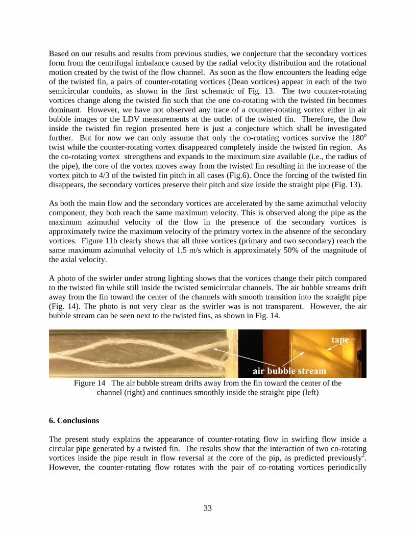
Based on our results and results from previous studies, we conjecture that the secondary vortices form from the centrifugal imbalance caused by the radial velocity distribution and the rotational motion created by the twist of the flow channel. As soon as the flow encounters the leading edge of the twisted fin, a pairs of counter-rotating vortices (Dean vortices) appear in each of the two semicircular conduits, as shown in the first schematic of Fig. 13. The two counter-rotating vortices change along the twisted fin such that the one co-rotating with the twisted fin becomes dominant. However, we have not observed any trace of a counter-rotating vortex either in air bubble images or the LDV measurements at the outlet of the twisted fin. Therefore, the flow inside the twisted fin region presented here is just a conjecture which shall be investigated further. But for now we can only assume that only the co-rotating vortices survive the 180o twist while the counter-rotating vortex disappeared completely inside the twisted fin region. As the co-rotating vortex strengthens and expands to the maximum size available (i.e., the radius of the pipe), the core of the vortex moves away from the twisted fin resulting in the increase of the vortex pitch to 4/3 of the twisted fin pitch in all cases (Fig.6). Once the forcing of the twisted fin disappears, the secondary vortices preserve their pitch and size inside the straight pipe (Fig. 13). As both the main flow and the secondary vortices are accelerated by the same azimuthal velocity component, they both reach the same maximum velocity. This is observed along the pipe as the maximum azimuthal velocity of the flow in the presence of the secondary vortices is approximately twice the maximum velocity of the primary vortex in the absence of the secondary vortices. Figure 11b clearly shows that all three vortices (primary and two secondary) reach the same maximum azimuthal velocity of 1.5 m/s which is approximately 50% of the magnitude of the axial velocity. A photo of the swirler under strong lighting shows that the vortices change their pitch compared to the twisted fin while still inside the twisted semicircular channels. The air bubble streams drift away from the fin toward the center of the channels with smooth transition into the straight pipe (Fig. 14). The photo is not very clear as the swirler was is not transparent. However, the air bubble stream can be seen next to the twisted fins, as shown in Fig. 14.
Figure 14 The air bubble stream drifts away from the fin toward the center of the
channel (right) and continues smoothly inside the straight pipe (left) 6. Conclusions The present study explains the appearance of counter-rotating flow in swirling flow inside a circular pipe generated by a twisted fin. The results show that the interaction of two co-rotating vortices inside the pipe result in flow reversal at the core of the pip, as predicted previously2. However, the counter-rotating flow rotates with the pair of co-rotating vortices periodically
34
crossing the horizontal axis where the LDV measurements are taken. This explains the periodic appearance of the counter-rotating velocity field. It is conjectured that the pair of co-rotating vortices originate inside the two spiral conduits formed by the twisted fin in the form of two pairs of counter-rotating vortices. However, the vortices co-rotating with the primary twisting direction of the fin survive while the counter-rotating vortices disappear, as shown schematically in Fig. 13. It is important to note that the presence of secondary vortices effectively doubles the local near-wall azimuthal velocity, which must have significant impact on heat transfer and near wall particulate agglomeration. Also, at the central core region of the pipe, mixing is increased due to the counter-rotating flow generated by the two co-rotating vortices. References [1] Abu-Khader M.M., “Further Understanding of Twisted fin Effects as Tube Insert for Heat Transfer Enhancement”, Heat and Mass Transfer, Vol. 43, pp. 123-134, (2006); [2] Aidun C.K., Parsheh M., “Spatially Periodic Reversing Core in a Twisted – Fin Generated Swirling Pipe Flow”, Physics of Fluids, Vol. 19, No. 6, (2007); [3] Alekseenko S.V., Kuibin P.A., Okulov V.L., Shtork S.I., “Helical Vortices in Swirl Flow”, Journal of Fluid Mechanics, Vol. 382, pp. 195-243, (1999); [4] Cheng K.C., Inaba T., Akiyama M., “Flow Visualization Studies of Secondary Flow Patterns and Centrifugal Instability in Curved Circular and Semicircular Pipes”, Proceedings of the 3rd International Symposium of Flow Visualization, Ann Arbor, MI, pp. 531-536, (1987); [5] Date A.W., “Prediction of Fully-Developed Flow in a Tube Containing a Twisted-Fin”, International Journal of Heat Mass Transfer, Vol. 17, 1974, pp. 845-859, (1974); [6] Dean W.R., “Note on the Motion of Fluid in a Curved Pipe”, The London, Edinburgh and Dublin Philosophical Magazine and Journal of Science, Series 7, Vol. 4, No. 20, pp. 208-223, (1927); [7] Dean W.R., “Fluid Motion in a Curved Channel”, Proceedings of the Royal Society of London, Series A, Vol. 121, No.787, pp. 402-420, (1928); [8] Eustice J., “Experiments on Stream-line Motion in Curved Pipes”, Proceedings of the Royal Society of London, Series A, Vol. 85, No. 576, pp. 119-131, (1911); [9] Farell C., Youssef S, “Experiments on Turbulence Management Using Screens and Honeycombs”, Journal of Fluids Engineering, Vol. 118, pp. 26-32, (1996); [10] Germano M., “On the Effect of Torsion on a Helical Pipe Flow”, Journal of Fluid Mechanics, Vol. 125, pp. 1-8, (1982); [11] Glover J., Bullen P.R., Cheeseman D.J., “The effects of refraction on the measurement of velocity of water flow in a circular pipe using a three beam laser Doppler anemometer system”, Proceedings of the Developments in Measurements and Instrumentation in Engineering, Durham, England, pp. 59-72, (1985); [12] Aidun, C.K.; “Method and Apparatus to Enhance Paper Forming,” Patent no. 5,792,321, issued Aug. 11, 1998; CIP Pat. no. 5,876,564 issued March 2, 1999; CIP Pat. no. 6,153,057 issued Nov. 28, 2000;

35
CIP Pat. No. 6,368,460 issued April 9, 2002. [13] Kao H.C., “Torsion Effect on Fully Developed Flow in a Helical Pipe”, Journal of Fluid Mechanics, Vol. 184, pp. 335-356, (1987); [14] Kazuhisa Y., Hidetoshi H., Saburo T., “Numerical Simulation on Heat Transfer Enhancement in Twisted-Fin-Inserted Tubes”, Journal of Enhanced Heat Transfer, Vol. 11, No. 4, pp.379-389, (2004); [15] Kreith F., Sonju O.K., “The Decay of a Turbulent Swirl in a Pipe”, Journal of Fluid Mechanics, Vol. 22, pp. 257-271, (1965); [16] Liu S., Masliyah J.H., “Axially Invariant Laminar Flow in Helical Pipes with Finite Pitch”, Journal of Fluid Mechanics, Vol. 251, pp. 315-353, (1993); [17] Manglik R.M., Maramaju S., Bergles A.E., “The Scaling and Correlation of Low Reynolds Number Swirl Flows and Friction Factors in Circular Tubes with Twisted-Fin Inserts”, Journal of Enhanced Heat Transfer, Vol. 8, No. 6, pp. 383-395, (2001); [18] Manglik R.M., Bergles A.E., “Heat Transfer and Pressure Drop Correlations for Twisted-Fin Inserts in Isothermal Tubes: Part I – Laminar Flows”, Journal of Heat Transfer, Vol. 115, No. 4, pp. 881-889, (1993); [19] Manglik R.M., Ranganathan C., “Visualization of Swirl Flows Generated by Twisted-Fin Insert in Circular Pipes”, Proceedings of the 4th World Conference on Experimental Heat Transfer, Fluid Mechanics and Thermodynamics, pp. 1631-1636, (1997); [20] Menon R., Lai W.T., “Key Considerations in the Selection of Seed Particles for LDV Measurements”, Presented at the 4th International Conference on Laser Anemometry, Cleveland, Ohio, August, (1991); [21] Rahmani R.K., “Three-Dimensional Numerical Simulation and Performance Study of an Industrial Helical Static Mixer”, University of Toledo, Ph.D. thesis, (2004); [22] Rahmani R.K., Keith T.G., Ayasoufi A., “Three-Dimensional Numerical Simulation and Performance Study of an Industrial Helical Static Mixer”, Journal of Fluids Engineering, Vol. 127, pp. 467-483, (2005); [23] Seymour E.V., “Fluid Flow Through Tubes Containing Twisted fins”, The Engineer, Vol. 222, , pp. 634-642, (1966); [24] Smithberg E., Landis F., “Friction and Forced Convection Heat Transfer Characteristics in Tubes with Twisted fin Swirl Generators”, Journal of Heat Transfer, Vol. 86, pp. 39-49, (1964); [25] Tiwari P., Antal S.P., Podowski M.Z., “Three-Dimensional Fluid Mechanics of Particulate Two-Phases Flows in U-Bend and Helical Conduits”, Physics of Fluids, Vol. 18, 043304, (2006);