Embed Size (px)
Citation preview
Fingertip Force Estimation via Inertial and Magnetic Sensors inDeformable Object Manipulation
Mostafa Mohammadi 1,2, Tommaso Lisini Baldi1,2, Stefano Scheggi 3, and Domenico Prattichizzo 1,2
Abstract— Fingertip contact forces are of utmost importancein evaluating the quality of the human grasp. However, mea-suring such forces during object manipulation is not a trivialtask. In this paper, we propose a novel method to estimatethe fingertip contact forces in grasping deformable objects withknown shape and stiffness matrix. The proposed approach usesa sensing glove instrumented with inertial and magnetic sensors.Data obtained from the accelerometers and gyroscopes placedon the distal phalanges are used to determine when the fingersestablish contacts with the object. The sensing glove is used toestimate the configuration of the hand and the deformation ofthe object at each contact with the fingertips of the human hand.The force exerted by each fingertip is obtained by multiplyingthe stiffness matrix of the object and the vector of object’slocal deformation in the contact point. Extensive simulationshave been performed in order to evaluate the robustness of theproposed approach to noisy measurements, and uncertaintiesin human hand model. In order to validate the proposedapproach, experimental validations with a virtual object havebeen performed. A haptic device was used to generate thecontact forces with the virtual object and accurately measurethe forces exerted by the users during the interaction.
I. INTRODUCTION
Contact forces determine the quality of a grasp in objectmanipulation for human and robotic hands. The knowledgeof the fingertip contact forces in grasping and manipulatingan object can be useful in a variety of research areas suchas: anatomical study [1], brain researches [2], rehabilitation[3], haptic rendering [4], [5], human action learning [6],human robot interaction [7], and sensorimotor control [8].For more than two decades data gloves, such as CyberGlove(CyberGlove Systems LLC, USA), based on arrays of resis-tive bend-sensors were the main reliable solution for handgesture detection [9]. Recently, results in force evaluationusing a sensing glove made by pressure sensors have beenpresented in [10], where the authors show a flexible andstretchable fabric-based tactile data glove to measure the
The research leading to these results has received funding from theEuropean Union Seventh Framework Programme FP7/2007-2013 undergrant agreement n. 601165 of the project “WEARHAP - WEARableHAPtics for humans and robots”, and from the European Union’s Horizon2020 research and innovation programme (H2020-ICT-645599) under grantagreement n. 645599 of the project ”SOMA: Soft-bodied intelligence forManipulation”.
1 Authors are with the Department of Information Engineering andMathematics, University of Siena, 53100 Siena, Italy. {mohammadi,lisini, prattichizzo}@diism.unisi.it
2 Authors are with the Department of Advanced Robotics, IstitutoItaliano di Tecnologia, Genova, 16163, Italy. {mostafa.mohammadi,tommaso.lisini, domenico.prattichizzo}@iit.it
3 Author is with the Surgical Robotics Laboratory, Departmentof Biomechanical Engineering, MIRA-Institute for Biomedical Technol-ogy and Technical Medicine, University of Twente, The [email protected]
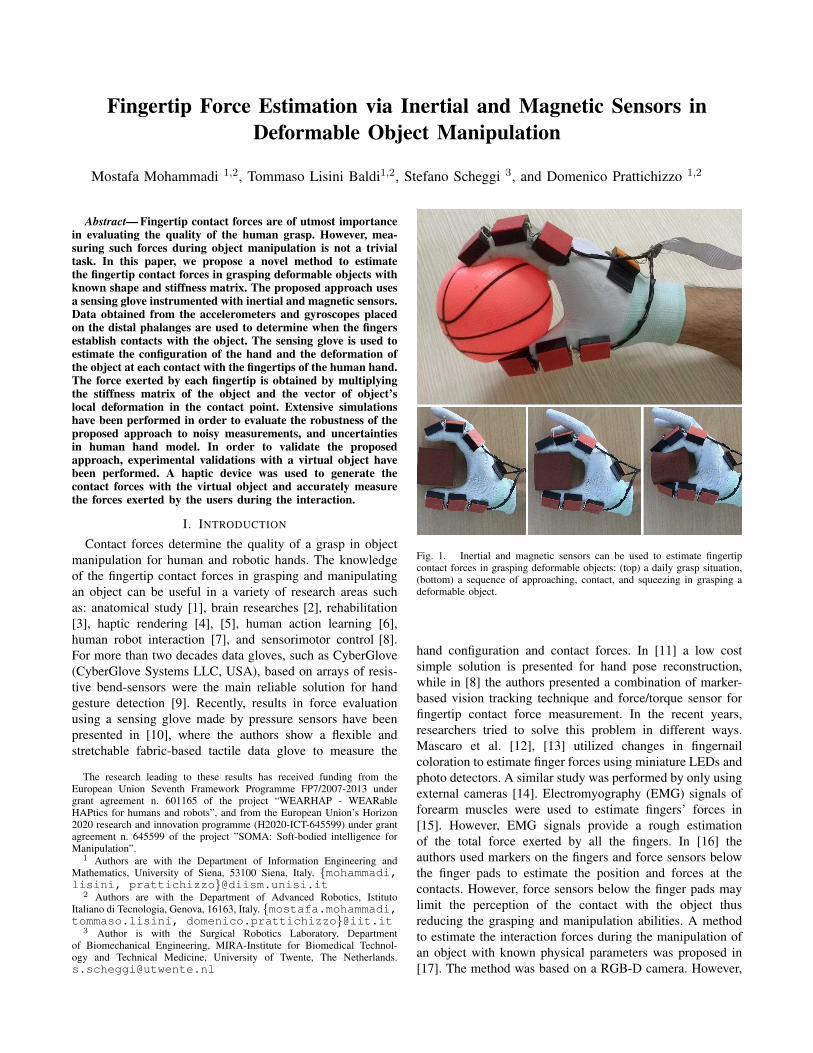
Fig. 1. Inertial and magnetic sensors can be used to estimate fingertipcontact forces in grasping deformable objects: (top) a daily grasp situation,(bottom) a sequence of approaching, contact, and squeezing in grasping adeformable object.
hand configuration and contact forces. In [11] a low costsimple solution is presented for hand pose reconstruction,while in [8] the authors presented a combination of marker-based vision tracking technique and force/torque sensor forfingertip contact force measurement. In the recent years,researchers tried to solve this problem in different ways.Mascaro et al. [12], [13] utilized changes in fingernailcoloration to estimate finger forces using miniature LEDs andphoto detectors. A similar study was performed by only usingexternal cameras [14]. Electromyography (EMG) signals offorearm muscles were used to estimate fingers’ forces in[15]. However, EMG signals provide a rough estimationof the total force exerted by all the fingers. In [16] theauthors used markers on the fingers and force sensors belowthe finger pads to estimate the position and forces at thecontacts. However, force sensors below the finger pads maylimit the perception of the contact with the object thusreducing the grasping and manipulation abilities. A methodto estimate the interaction forces during the manipulation ofan object with known physical parameters was proposed in[17]. The method was based on a RGB-D camera. However,
vision based approaches still suffer from occlusion and needexternal and non wearable equipments.
By using multi-axes force/torque sensors to measure thecontact forces (such as the three degrees of freedom (DoF)approach presented in [18] and the 6-DoF approach presentedin [8]) the results might be precise in force measurement.However, heavy equipment and metal parts surrounding thefinger pads might cause losing the cutaneous perceptionsignificantly. Moreover, multi-axes force/torque sensors stillneed a tracking system, e.g., Vicon (Vicon Motion Systems,UK) or PhaseSpace (PhaseSpace Motion Capture, USA),to estimate the hand pose and contact points. Data glovesbased on inertial and magnetic sensors for hand tracking arepresented in [19], [20].
In this paper we propose a new technique for fingertipcontact force estimation in grasping deformable objects.The method uses Magnetical, Angular Rate, and Gravity(MARG) sensors to estimate the fingertip contact forces.The proposed system is wearable and allows unlimitedworkspace. In the proposed approach, we considered neg-ligible rolling and skidding of the fingertips over the object,negligible finger pad deformation compared to the objectdeformation (hard finger model), and fixed object’s posew.r.t. the palm. We assumed that the stiffness matrix of theobject is fixed and does not change with its deformation.
In the proposed approach, the joint angles of the fingersand the orientation of the palm are provided by the MARGsensors of the sensing glove. Then, by considering thekinematic model of the hand, the pose of each fingertip isestimated with respect to the palm [20]. The MARGs areinstalled on the phalanges and palm (Fig. 1) and measure ac-celeration, angular rate and magnetic field. Since accelerom-eter and gyroscope are sensitive to impact, we can use theirinformation to detect the contact events. In fact, when afingertip touches an object, it is subject to a fast change inthe acceleration (and angular velocity), so we can detect thecontact time analyzing the raw data of accelerometer andgyroscope. Once a contact event is detected, the positionof the corresponding fingertip is considered as the contactframe origin on the object. The axes of the contact frame aredefined as follows: two axes are tangent to the object surfaceand third one (normal axis) points inside the object. For adeformable object with known stiffness matrix, neglectingthe change in stiffness matrix due to local deformation, theapplied force of each fingertip during the contact is obtainedby multiplying the stiffness matrix and the fingertip positionvector w.r.t. the contact frame.
Error sources in this method are: hand model errors(including the length of phalanges, and configuration ofthe hand), MARG measurement errors (including bias andnoise), delay in contact event detection, and object’s stiffnessmatrix error. The palm configuration error, i.e., error in theplacement of MCP and TM joints, and the phalanges lengthcan cause error in both magnitude and direction of the forces.Thus, an accurate model of the hand improves the accuracyof the estimated forces. Errors in the orientation measure-ment of each MARG are the most important error sources
of this approach. Therefore, appropriate calibration of theMARGs is important in order to have a better estimation offorces. Delay in contact event detection can also be a reasonfor error in the direction and amplitude of the estimatedforces. It can be reduced by increasing the sampling rate ofthe sensors. Finally, errors in estimating the object stiffnessmatrix cause error in the estimation of the fingertip contactforces.
A simulation study has been performed to evaluate therobustness of the proposed approach and to understand howthe error sources affect the results of the proposed algorithm.Preliminary experiment with virtual objects were performedin order to validate the proposed approach. An omega.3(Force Dimension, Switzerland) haptic device was used toprovide the user with the contact forces with the object andaccurately measure the forces exerted by the user during theinteraction.
The rest of the paper is organized as follows. Section IIreviews the sensing glove made by inertial and magneticsensor. Section III explains the fingertip contact force es-timation algorithm. Section IV and Section V report theresults of simulation and experimental validations. Finally,in Section VI conclusions are drawn and possible subjectsof future research are outlined.
II. HAND POSE ESTIMATION USING INERTIAL ANDMAGNETIC SENSORS.
In this section we briefly describe the design of theMARG sensing glove, and the algorithms used to esti-mate the hand’s pose. The proposed glove is based onthe design presented in [20]. In this preliminary study weinstrumented only the thumb and the index finger. Theprototype is made by seven MARG sensors: one on thepalm, three on the thumb, and three on the index fingeras depicted in Fig. 1. Each MARG sensor utilizes a triax-ial accelerometer/gyroscope (InvenSense MPU6050) and atriaxial magneto-resistor (Honeywell HMC5883L). The rawdata of all the sensors are transmitted to an external PCthrough serial port at 115200 bps. All the pre-processingand calculations are performed by the external PC.
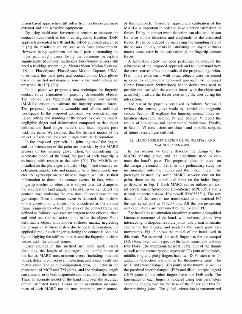
The hand’s pose estimation algorithm assumes a simplifiedkinematic structure of the hand, with universal joints (twointersecting, orthogonal revolute joints) and planar kinematicchains for the fingers, and neglects the small joint axismovements. Fig. 2 shows the model of the hand used inthis work. We assumed that each finger has the metacarpal(MC) bone fixed with respect to the hand frame, and featuresfour DoFs. The trapeziometacarpal (TM) joint of the thumbas well as the metacarpophalangeal (MCP) joint of the index,middle, ring and pinky fingers have two DoFs each (one foradduction/abduction and another for flexion/extension). TheMCP and interphalangeal (IP) joints of the thumb, as well asthe proximal interphalangeal (PIP) and distal interphalangeal(DIP) joints of the other fingers have one DoF each. Thekinematics of each finger is modeled using four parametersencoding angles, two for the base of the finger and two forthe remaining joints. The global orientation is parametrized
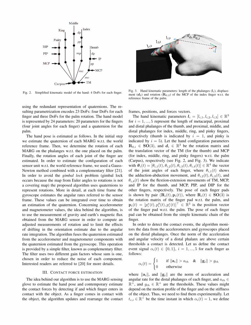
Fig. 2. Simplified kinematic model of the hand: 4 DoFs for each finger.
using the redundant representation of quaternions. The re-sulting parametrization encodes 23 DoFs: four DoFs for eachfinger and three DoFs for the palm rotation. The hand modelis represented by 24 parameters: 20 parameters for the fingers(four joint angles for each finger) and a quaternion for thepalm.
The hand pose is estimated as follows. In the initial stepwe estimate the quaternion of each MARG w.r.t. the worldreference frame. Then, we determine the rotation of eachMARG on the phalanges w.r.t. the one placed on the palm.Finally, the rotation angles of each joint of the finger areestimated. In order to estimate the configuration of eachsensor unit w.r.t. the world reference frame, we used a Gauss-Newton method combined with a complementary filter [21].In order to avoid the gimbal lock problem (gimbal lockoccurs because the map from Euler angles to rotations is nota covering map) the proposed algorithm uses quaternions torepresent rotations. More in detail, at each time frame thegyroscope estimates the angular rates referred to the sensorframe. These values can be integrated over time to obtainan estimation of the quaternion. Concerning accelerometerand magnetometer values, the idea behind the algorithm, isto use the measurement of gravity and earth’s magnetic fluxobtained from the MARG sensor in order to compute anadjusted measurements of rotation and to limit the effectsof drifting in the orientation estimate due to the angularrate integration. The algorithm fuses the quaternion estimatedfrom the accelerometer and magnetometer components withthe quaternion estimated from the gyroscope. This operationis provided by a simple filter, known as complementary filter.The filter uses two different gain factors whose sum is one,chosen in order to reduce the noise of each component.Interested readers are referred to [20] for more details.
III. CONTACT FORCE ESTIMATION
The idea behind our algorithm is to use the MARG sensingglove to estimate the hand pose and contemporary estimatethe contact forces by detecting if and which finger enters incontact with the object. As a finger comes in contact withthe object, the algorithm updates and rearrange the contact
Fig. 3. Hand kinematic parameters: length of the phalanges (li), displace-ment (d2) and rotation (R0,2) of the MCP of the index finger w.r.t. thereference frame of the palm.
frames, positions, and forces vectors.The hand kinematic parameters li = [li,1, li,2, li,3] ∈ R3
for i = 1, ..., 5 represent the length of metacarpal, proximaland distal phalanges of the thumb, and proximal, middle, anddistal phalanges for index, middle, ring, and pinky fingers,respectively (thumb is indicated by i = 1, and pinky isindicated by i = 5). Let the hand configuration parametersR0,i ∈ SO(3), and di ∈ R3 be the rotation matrix andthe translation vector of the TM (for the thumb) and MCP(for index, middle, ring, and pinky fingers) w.r.t. the palm(Carpus), respectively (see Fig. 2, and Fig. 3). We indicatewith θi(t) = [θi,1(t), θi,2(t), θi,3(t), θi,4(t)] ∈ R4 the vectorof the joint angles of each finger, where θi,1(t) showsthe adduction-abduction movement, and θi,2(t), θi,3(t), andθi,4(t) show the flextion-extension movements of TM, MCP,and IP for the thumb, and MCP, PIP, and DIP for theother fingers, respectively. The pose of each finger padsis shown by pair (Ri(t),pi(t)), where Ri(t) ∈ SO(3) isthe rotation matrix of the finger pad w.r.t. the palm, andpi(t) = [pxi (t), p
yi (t), p
zi (t)]
> ∈ R3 is the position vectorof the finger pad w.r.t. the palm. The pose of each fingerpad can be obtained from the simple kinematic chain of thefinger.
In order to detect the contact events, the algorithm moni-tors the data from the accelerometers and gyroscopes placedon the distal phalanges. Once the norm of the accelerationand angular velocity of a distal phalanx are above certainthresholds a contact is detected. Let us define the contactevent signal αi(t) ∈ {0, 1}, i = 1, ..., 5 for each finger asfollows:
αi(t) =
{1 if ‖ai‖ > ath & ‖gi‖ > gth
0 otherwise
where ‖ai‖, and ‖gi‖ are the norm of acceleration andangular rate for the distal phalanges of each finger, and ath ∈R+, and gth ∈ R+ are the thresholds. These values mightdepend on the motion profile of the finger and on the stiffnessof the object. Thus, we need to find them experimentally. Lettc,i ∈ R+ be the time instant in which αi(t) = 1, we define
a new contact frame Ci = 〈Oi,xi,yi, zi〉 where Oi is theorigin of the contact frame, whose distance from the palm isequal to pi(tc,i), two of its axes (yi and zi) are tangent tothe surface of the object, and xi is the normal component ofthe coordinate frame pointing inside the object. Let Ri(tc,i)be the rotation matrix of such coordinate frame w.r.t. palm.The position of each fingertip w.r.t. the new contact framepc,i(t) = [pxc,i(t), p
yc,i(t), p
zc,i(t)]
> ∈ R3 can be obtained by:
pc,i(t) = R>i (tc,i)(pi(t)− pi(tc,i))
For an object with known stiffness matrix Ko ∈ R3×3
the force applied by each finger to the object in the contactframe is:
λi(t) =
{Kopc,i(t) if pxc,i(t) > 0
0 otherwise
where λi(t) = [λxi (t), λyi (t), λ
zi (t)]
> ∈ R3 is the forcevector in the contact frame Ci and pxc,i(t) is the normalcomponent of pc,i(t).
An accurate hand kinematic and configuration parameters(li, R0,i, and di) improve the accuracy of the force esti-mation using MARG sensors. Furthermore, an appropriatecalibration procedure reduces bias and noise, and decreasesthe force estimation error. Moreover, using a high samplingtime for the sensors results in a lower delay in contactevent detection, and improves the accuracy of the proposedapproach. A precise model of the stiffness matrix of the ma-nipulated object leads to a better estimation of the fingertipcontact forces.
IV. SIMULATION RESULTS
In order to evaluate the robustness of the proposed ap-proach, and to deeply investigate the effects of various errorsources, simulation studies have been performed. We simu-lated the bone and joint structures of the anthropomorphichand. A MARG is considered for the palm and all phalanges.The data provided by the MARGs (orientation w.r.t. globalframe) is used to reproduce the hand articulation pose.Contact event signals for each fingertip are simulated, soat the contact event time instances, the signal is logicallyhigh, and in all other moments it is logically low (similar tothe real system). Simulations have been done in Simulink®
using SimMechanicsTM with a sampling time of 1 ms.The simulation scenario is as follows. The deformable
manipulated object is a sphere with 6 cm radius, and stiffnessmatrix Ko = diag[1000, 1000, 1000] (N/m), initially locatedat [50,−30,−70] mm w.r.t. palm. In the first five secondsthe palm is fixed and the fingers approaching the objectin a synergistic manner, each finger establishes a contactin different times (t ∈ [0 5)) while grasping the object;then, in next five seconds (t ∈ [5 10)) the fingers keepthe contacts and the palm starts to rotate around its y-axiswith a constant velocity up to 60 deg. In the next fiveseconds (t ∈ [10 15)) the palm goes back to its initialorientation while the fingers do not move. In the last fiveseconds (t ∈ [15 20)) the palm is fixed while the fingersare releasing the object in a synergistic manner.
TABLE IHAND PARAMETERS AND PALM CONFIGURATION VALUES
hand parameters nominal values real values
l1 (mm) [40, 30, 28] [40.29, 27.40, 21.60]l2 (mm) [37, 24, 23] [35.95, 24.96, 27.96]d1 (mm) [20, 0, 0] [13.55, 0, 0]d2 (mm) [18.12, 67.61, 0] [18.04, 67.34, 0]R0,1 I3 I3R0,2 I3 I3
TABLE IINUMERICAL VALUES OF THE ERROR SOURCES USED FOR SIMULATION
Error source values
Delay in contact detection (ms) 30Error in link lengths li (mm) N(0, 5)Error in hand configuration parameter di (mm) N(0, 5)Bias of MARGs’ orientation for each angle (deg) N(0, 2)Noise of MARGs’ orientation for each angle (deg) N(0, 0.5)Stiffness matrix (N/m) 0
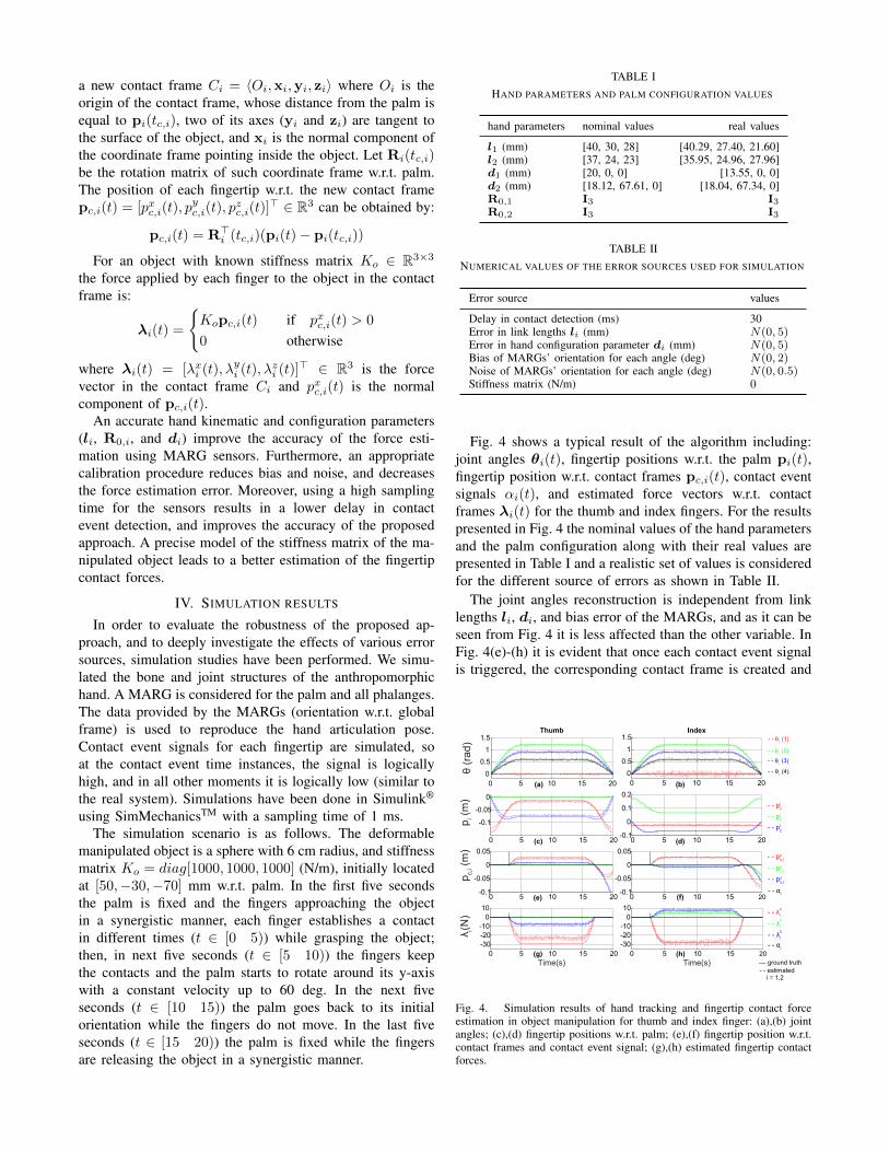
Fig. 4 shows a typical result of the algorithm including:joint angles θi(t), fingertip positions w.r.t. the palm pi(t),fingertip position w.r.t. contact frames pc,i(t), contact eventsignals αi(t), and estimated force vectors w.r.t. contactframes λi(t) for the thumb and index fingers. For the resultspresented in Fig. 4 the nominal values of the hand parametersand the palm configuration along with their real values arepresented in Table I and a realistic set of values is consideredfor the different source of errors as shown in Table II.
The joint angles reconstruction is independent from linklengths li, di, and bias error of the MARGs, and as it can beseen from Fig. 4 it is less affected than the other variable. InFig. 4(e)-(h) it is evident that once each contact event signalis triggered, the corresponding contact frame is created and
0 5 10 15 200
0.51
1.5
θ (r
ad)
Thumb
0 5 10 15 200
0.51
1.5Index
0 5 10 15 20
-0.1
-0.05
0
p i (m
)
0 5 10 15 20-0.1
0
0.1
0.2
0 5 10 15 20-0.1
-0.05
0
0.05
p c,i (
m)
0 5 10 15 20-0.1
-0.05
0
0.05
0 5 10 15 20-30-20-10
010
Time(s)
λi(N
)
0 5 10 15 20-30-20-10
010
Time(s)
- - pxc,i
- - pxi
- - λix
__ ground truth - - estimated
i = 1,2
- - θi (1)
(a)
(c)
(e)
(g)
(b)
(d)
(f)
(h)
- - θi (2)- - θi (3)
- - θi (4)
- - pyi
- - pzi
- - pyc,i
- - pzc,i
- - αi
- - λi
y
- - λi
z - - αi
Fig. 4. Simulation results of hand tracking and fingertip contact forceestimation in object manipulation for thumb and index finger: (a),(b) jointangles; (c),(d) fingertip positions w.r.t. palm; (e),(f) fingertip position w.r.t.contact frames and contact event signal; (g),(h) estimated fingertip contactforces.
σ (deg)-0.5 0 0.5 1 1.5 2 2.50
2
4
6
8
10
12
λ (N
)a
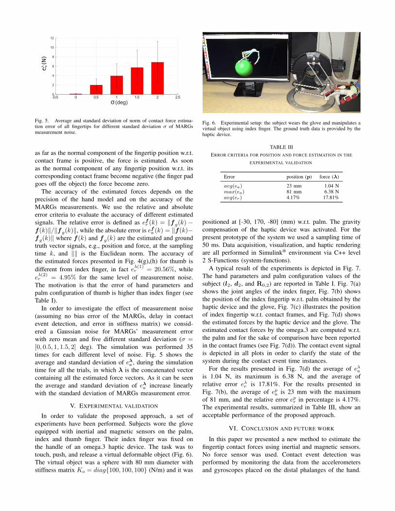
Fig. 5. Average and standard deviation of norm of contact force estima-tion error of all fingertips for different standard deviation σ of MARGsmeasurement noise.
as far as the normal component of the fingertip position w.r.t.contact frame is positive, the force is estimated. As soonas the normal component of any fingertip position w.r.t. itscorresponding contact frame become negative (the finger padgoes off the object) the force become zero.
The accuracy of the estimated forces depends on theprecision of the hand model and on the accuracy of theMARGs measurements. We use the relative and absoluteerror criteria to evaluate the accuracy of different estimatedsignals. The relative error is defined as efr (k) = ‖fg(k) −f(k)‖/‖fg(k)‖, while the absolute error is efa (k) = ‖f(k)−fg(k)‖ where f(k) and fg(k) are the estimated and groundtruth vector signals, e.g., position and force, at the samplingtime k, and ‖‖ is the Euclidean norm. The accuracy ofthe estimated forces presented in Fig. 4(g),(h) for thumb isdifferent from index finger, in fact eλ(1)r = 20.56%, whileeλ(2)r = 4.95% for the same level of measurement noise.
The motivation is that the error of hand parameters andpalm configuration of thumb is higher than index finger (seeTable I).
In order to investigate the effect of measurement noise(assuming no bias error of the MARGs, delay in contactevent detection, and error in stiffness matrix) we consid-ered a Gaussian noise for MARGs’ measurement errorwith zero mean and five different standard deviation (σ =[0, 0.5, 1, 1.5, 2] deg). The simulation was performed 35times for each different level of noise. Fig. 5 shows theaverage and standard deviation of eλa , during the simulationtime for all the trials, in which λ is the concatenated vectorcontaining all the estimated force vectors. As it can be seenthe average and standard deviation of eλa increase linearlywith the standard deviation of MARGs measurement error.
V. EXPERIMENTAL VALIDATION
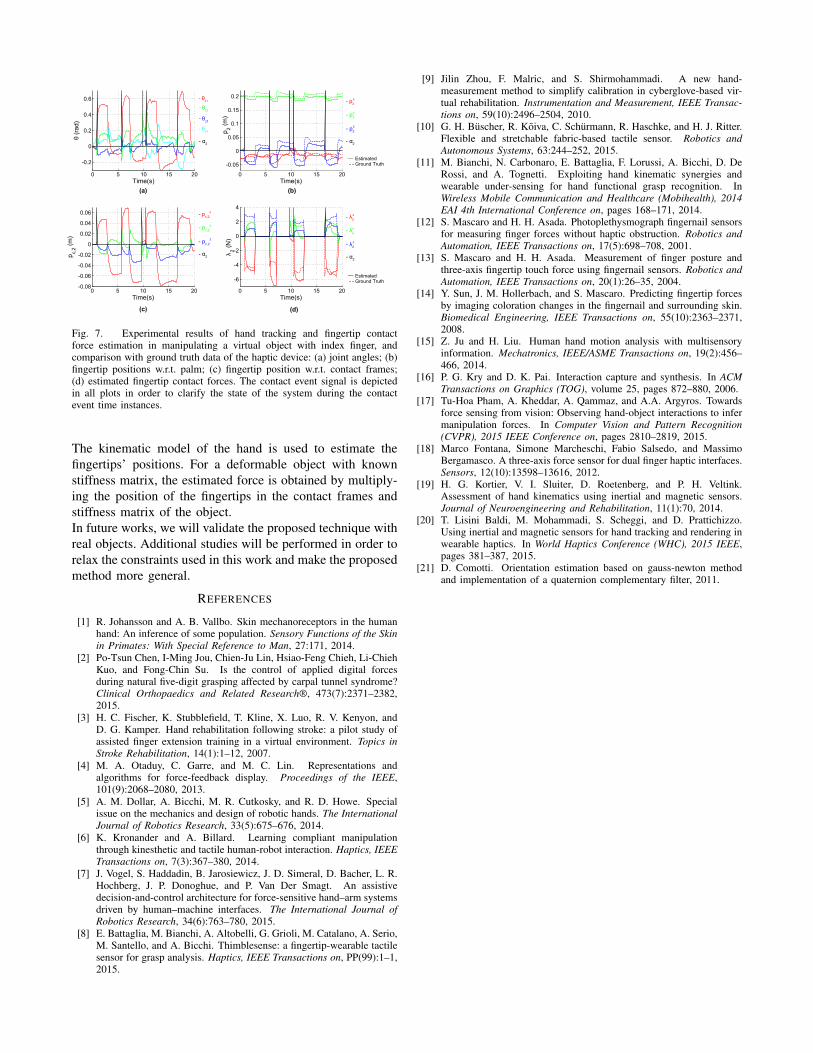
In order to validate the proposed approach, a set ofexperiments have been performed. Subjects wore the gloveequipped with inertial and magnetic sensors on the palm,index and thumb finger. Their index finger was fixed onthe handle of an omega.3 haptic device. The task was totouch, push, and release a virtual deformable object (Fig. 6).The virtual object was a sphere with 80 mm diameter withstiffness matrix Ko = diag{100, 100, 100} (N/m) and it was
Fig. 6. Experimental setup: the subject wears the glove and manipulates avirtual object using index finger. The ground truth data is provided by thehaptic device.
TABLE IIIERROR CRITERIA FOR POSITION AND FORCE ESTIMATION IN THE
EXPERIMENTAL VALIDATION
Error position (p) force (λ)
avg(ea) 23 mm 1.04 Nmax(ea) 81 mm 6.38 Navg(er) 4.17% 17.81%
positioned at [-30, 170, -80] (mm) w.r.t. palm. The gravitycompensation of the haptic device was activated. For thepresent prototype of the system we used a sampling time of50 ms. Data acquisition, visualization, and haptic renderingare all performed in Simulink® environment via C++ level2 S-Functions (system-functions).
A typical result of the experiments is depicted in Fig. 7.The hand parameters and palm configuration values of thesubject (l2, d2, and R0,2) are reported in Table I. Fig. 7(a)shows the joint angles of the index finger, Fig. 7(b) showsthe position of the index fingertip w.r.t. palm obtained by thehaptic device and the glove, Fig. 7(c) illustrates the positionof index fingertip w.r.t. contact frames, and Fig. 7(d) showsthe estimated forces by the haptic device and the glove. Theestimated contact forces by the omega.3 are computed w.r.t.the palm and for the sake of comparison have been reportedin the contact frames (see Fig. 7(d)). The contact event signalis depicted in all plots in order to clarify the state of thesystem during the contact event time instances.
For the results presented in Fig. 7(d) the average of eλais 1.04 N, its maximum is 6.38 N, and the average ofrelative error eλr is 17.81%. For the results presented inFig. 7(b), the average of epa is 23 mm with the maximumof 81 mm, and the relative error epr in percentage is 4.17%.The experimental results, summarized in Table III, show anacceptable performance of the proposed approach.
VI. CONCLUSION AND FUTURE WORK
In this paper we presented a new method to estimate thefingertip contact forces using inertial and magnetic sensors.No force sensor was used. Contact event detection wasperformed by monitoring the data from the accelerometersand gyroscopes placed on the distal phalanges of the hand.
0 5 10 15 20
-0.2
0
0.2
0.4
0.6
Time(s)
θ (ra
d)
0 5 10 15 20
-0.05
0
0.05
0.1
0.15
0.2
p 2 (m)
Time(s)
0 5 10 15 20-0.08
-0.06
-0.04
-0.02
0
0.02
0.04
0.06
p c,2 (m
)
Time(s)0 5 10 15 20
-6
-4
-2
0
2
4
λ 2 (N)
Time(s)
- p2x
- α2
__ Estimated - - Ground Truth
(a)
(c)
(b)
(d)
- θ22
- θ23
- θ24
- θ21
- p2y
- p2z
- α2
- pc,2x
- pc,2y
- pc,2z
- α2
- λ2x
- λ2y
- λ2z
- α2
__ Estimated - - Ground Truth
Fig. 7. Experimental results of hand tracking and fingertip contactforce estimation in manipulating a virtual object with index finger, andcomparison with ground truth data of the haptic device: (a) joint angles; (b)fingertip positions w.r.t. palm; (c) fingertip position w.r.t. contact frames;(d) estimated fingertip contact forces. The contact event signal is depictedin all plots in order to clarify the state of the system during the contactevent time instances.
The kinematic model of the hand is used to estimate thefingertips’ positions. For a deformable object with knownstiffness matrix, the estimated force is obtained by multiply-ing the position of the fingertips in the contact frames andstiffness matrix of the object.In future works, we will validate the proposed technique withreal objects. Additional studies will be performed in order torelax the constraints used in this work and make the proposedmethod more general.
REFERENCES
[1] R. Johansson and A. B. Vallbo. Skin mechanoreceptors in the humanhand: An inference of some population. Sensory Functions of the Skinin Primates: With Special Reference to Man, 27:171, 2014.
[2] Po-Tsun Chen, I-Ming Jou, Chien-Ju Lin, Hsiao-Feng Chieh, Li-ChiehKuo, and Fong-Chin Su. Is the control of applied digital forcesduring natural five-digit grasping affected by carpal tunnel syndrome?Clinical Orthopaedics and Related Research®, 473(7):2371–2382,2015.
[3] H. C. Fischer, K. Stubblefield, T. Kline, X. Luo, R. V. Kenyon, andD. G. Kamper. Hand rehabilitation following stroke: a pilot study ofassisted finger extension training in a virtual environment. Topics inStroke Rehabilitation, 14(1):1–12, 2007.
[4] M. A. Otaduy, C. Garre, and M. C. Lin. Representations andalgorithms for force-feedback display. Proceedings of the IEEE,101(9):2068–2080, 2013.
[5] A. M. Dollar, A. Bicchi, M. R. Cutkosky, and R. D. Howe. Specialissue on the mechanics and design of robotic hands. The InternationalJournal of Robotics Research, 33(5):675–676, 2014.
[6] K. Kronander and A. Billard. Learning compliant manipulationthrough kinesthetic and tactile human-robot interaction. Haptics, IEEETransactions on, 7(3):367–380, 2014.
[7] J. Vogel, S. Haddadin, B. Jarosiewicz, J. D. Simeral, D. Bacher, L. R.Hochberg, J. P. Donoghue, and P. Van Der Smagt. An assistivedecision-and-control architecture for force-sensitive hand–arm systemsdriven by human–machine interfaces. The International Journal ofRobotics Research, 34(6):763–780, 2015.
[8] E. Battaglia, M. Bianchi, A. Altobelli, G. Grioli, M. Catalano, A. Serio,M. Santello, and A. Bicchi. Thimblesense: a fingertip-wearable tactilesensor for grasp analysis. Haptics, IEEE Transactions on, PP(99):1–1,2015.
[9] Jilin Zhou, F. Malric, and S. Shirmohammadi. A new hand-measurement method to simplify calibration in cyberglove-based vir-tual rehabilitation. Instrumentation and Measurement, IEEE Transac-tions on, 59(10):2496–2504, 2010.
[10] G. H. Buscher, R. Koiva, C. Schurmann, R. Haschke, and H. J. Ritter.Flexible and stretchable fabric-based tactile sensor. Robotics andAutonomous Systems, 63:244–252, 2015.
[11] M. Bianchi, N. Carbonaro, E. Battaglia, F. Lorussi, A. Bicchi, D. DeRossi, and A. Tognetti. Exploiting hand kinematic synergies andwearable under-sensing for hand functional grasp recognition. InWireless Mobile Communication and Healthcare (Mobihealth), 2014EAI 4th International Conference on, pages 168–171, 2014.
[12] S. Mascaro and H. H. Asada. Photoplethysmograph fingernail sensorsfor measuring finger forces without haptic obstruction. Robotics andAutomation, IEEE Transactions on, 17(5):698–708, 2001.
[13] S. Mascaro and H. H. Asada. Measurement of finger posture andthree-axis fingertip touch force using fingernail sensors. Robotics andAutomation, IEEE Transactions on, 20(1):26–35, 2004.
[14] Y. Sun, J. M. Hollerbach, and S. Mascaro. Predicting fingertip forcesby imaging coloration changes in the fingernail and surrounding skin.Biomedical Engineering, IEEE Transactions on, 55(10):2363–2371,2008.
[15] Z. Ju and H. Liu. Human hand motion analysis with multisensoryinformation. Mechatronics, IEEE/ASME Transactions on, 19(2):456–466, 2014.
[16] P. G. Kry and D. K. Pai. Interaction capture and synthesis. In ACMTransactions on Graphics (TOG), volume 25, pages 872–880, 2006.
[17] Tu-Hoa Pham, A. Kheddar, A. Qammaz, and A.A. Argyros. Towardsforce sensing from vision: Observing hand-object interactions to infermanipulation forces. In Computer Vision and Pattern Recognition(CVPR), 2015 IEEE Conference on, pages 2810–2819, 2015.
[18] Marco Fontana, Simone Marcheschi, Fabio Salsedo, and MassimoBergamasco. A three-axis force sensor for dual finger haptic interfaces.Sensors, 12(10):13598–13616, 2012.
[19] H. G. Kortier, V. I. Sluiter, D. Roetenberg, and P. H. Veltink.Assessment of hand kinematics using inertial and magnetic sensors.Journal of Neuroengineering and Rehabilitation, 11(1):70, 2014.
[20] T. Lisini Baldi, M. Mohammadi, S. Scheggi, and D. Prattichizzo.Using inertial and magnetic sensors for hand tracking and rendering inwearable haptics. In World Haptics Conference (WHC), 2015 IEEE,pages 381–387, 2015.
[21] D. Comotti. Orientation estimation based on gauss-newton methodand implementation of a quaternion complementary filter, 2011.


![Inertial Odometry on Handheld Smartphones · Inertial odometry is concerned with estimation of the change of position over time. The extensive survey of Harle [17] covers many approaches](https://img.pdfslide.net/doc/110x75/5e20397c5606a777765a5caa/inertial-odometry-on-handheld-smartphones-inertial-odometry-is-concerned-with-estimation.jpg)


![Walk Distance Estimation Using an Ankle- mounted Inertial ... · [2], which often place the inertial sensors in the waist [3], wrist [4], hand or pocket. Since this information is](https://img.pdfslide.net/doc/110x75/6029ccf9c25adc5db81ba85d/walk-distance-estimation-using-an-ankle-mounted-inertial-2-which-often-place.jpg)