Embed Size (px)
Citation preview
_____
17
Chapter 3
THERMAL ACTION
3.1. GENERAL
The thermal action represents the action of the fire on the structure and
Eurocode 1 gives different possibilities for the thermal action to be
considered.
One possibility consists of time-temperature relationships. These are
relationships that give the evolution as a function of time of a temperature
that could be the temperature of the gases surrounding the structure. This
temperature, together with the appropriate boundary conditions, can be used
to determine the heat flux transmitted from the environment1 to the structure.
Another possibility consists of relationships that give directly the heat
flux impinging on the structure. This impinging heat flux is then combined
with the flux reemitted by the structure to determine the evolution of the
temperature in the structure.
In Eurocode 1, the distinction is made between nominal
temperature-time curves, on one hand, and natural fire models on the other
hand.
The thermal action to be used is normally a legal requirement defined
by the country or region where the building is located and depending on its
size, use and occupancy.
Some countries give prescriptive requirements that define both the
time-temperature curve and the time (called the fire resistance) the structure
must survive when exposed to this curve. For example, a hotel located in the
city A must have a resistance to the standard curve of 60 minutes, whereas a
1 i.e., the fire, the hot gases and the walls of the compartment.
Fire Design of Steel Structures Jean-Marc Franssen and Paulo Vila Real© 2012 ECCS – European Convention for Constructional Steelwork. Published 2012 by ECCS – European Convention for Constructional Steelwork
3. THERMAL ACTION
_____
18
railways station located in a city B must have a resistance to the hydrocarbon
curve of 30 minutes. In such cases, the designer must ensure that the
structure complies with the requirement and he must use the prescribed
time-temperature curve.
In other countries or regions, the legal environment may be more
flexible and allow the designer to make a performance based design. In such
a case, it is the responsibility of the designer to use an appropriate
representation of the fire, although the Eurocode gives some guidance in the
form of limits of application to some of the proposed natural fire models.
Ideally, such natural fire models should be used with performance based
requirements linked, for example, to the time required for evacuation or
intervention. It is recommended to have approval of the authority having
jurisdiction on the design fire and design scenario before starting any
performance-based design.
3.2. NOMINAL TEMPERATURE-TIME CURVES
Temperature-time curves are analytical functions of time that give a
temperature. The term curve comes from the fact that these functions are
continuous and can be used to draw a curve in a time-temperature plane.
They are called nominal because they are not supposed to represent a
real fire. They have to be considered as conventional, or arbitrary, functions.
This is why the term fire curve is rather inappropriate because it implies that
the temperature is the temperature of a fire. In fact, the temperature is of the
same order of magnitude as temperatures observed in fires. Because they are
conventional, such relationships are thus to be used in a prescriptive
regulatory environment. Any requirement that is expressed in terms of a
nominal curve is thus also prescriptive and, in a sense, arbitrary. The
resistance of a structure to a nominal fire should not be compared to the
duration required for evacuation or intervention.
Eurocode 1 proposes three different nominal temperature-time curves.
The standard temperature-time curve is the one that has been
historically used, and it is still used today, in standard fire tests to rate
structural and separating elements. It is used to represent a fully developed
fire in a compartment. It is often referred to as the ISO curve because the
expression was taken from the ISO 834 standard. This standard curve is
3.2. NOMINAL TEMPERATURE-TIME CURVES
_____
19
given by Eq. (3.1).
1020 345log 8 1g t (3.1)
where g is the gas temperature in °C and t is the time in minutes.
The external time-temperature curve is used for the outside surface of
separating external walls which are exposed to fire from different parts of
the façade. The fire exposure can come either directly from the inside of the
fire compartment or from a compartment situated below or adjacent to the
external wall. Because external walls are rarely made of steel, this curve is
not relevant for steel structures.
This curve should not be used for calculating the effects of a fire on an
external load bearing structure, for example steel beams and columns,
located outside the envelope of the building. The thermal attack on external
structural steel elements is described in Annex B of Eurocode 1.
The external curve is given by Eq. (3.2).
0.32 3.820 660 1 0.687 0.313t t
g e e (3.2)
The hydrocarbon time-temperature curve is used for representing the
effects of a hydrocarbon type fire. It is given by Eq. (3.3).
0.167 2.520 1080 1 0.325 0.675t t
g e e (3.3)
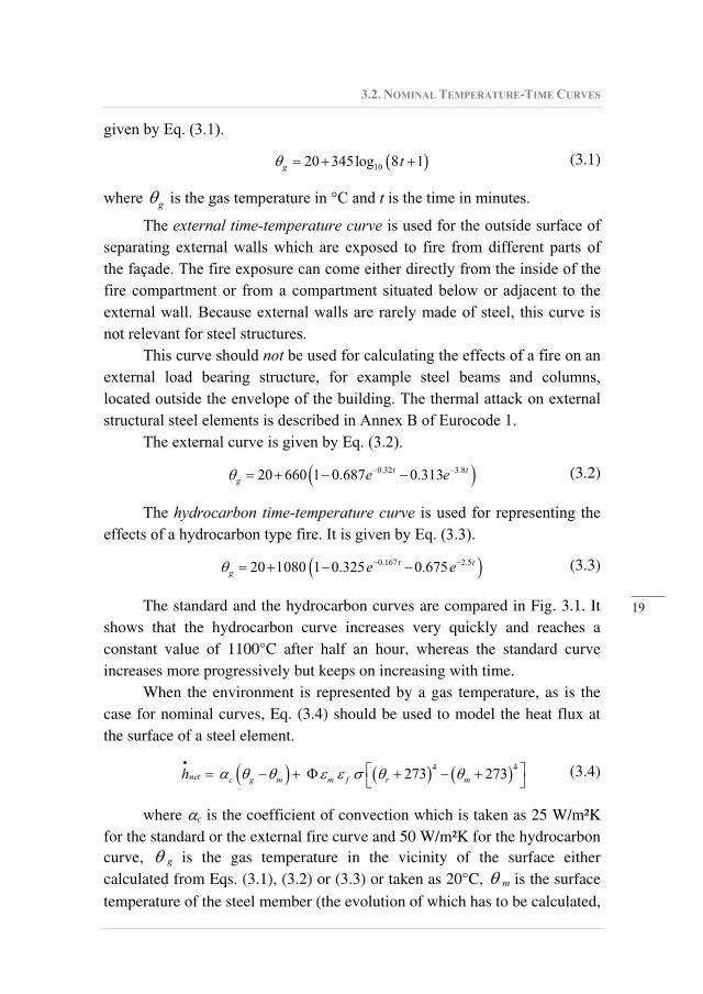
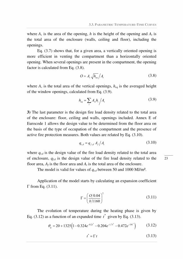
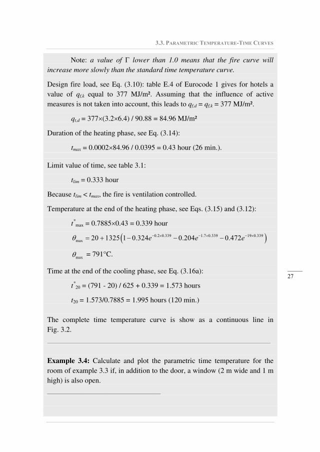
The standard and the hydrocarbon curves are compared in Fig. 3.1. It
shows that the hydrocarbon curve increases very quickly and reaches a
constant value of 1100°C after half an hour, whereas the standard curve
increases more progressively but keeps on increasing with time.
When the environment is represented by a gas temperature, as is the
case for nominal curves, Eq. (3.4) should be used to model the heat flux at
the surface of a steel element.
4 4273 273net c g m m f r mh (3.4)
where c is the coefficient of convection which is taken as 25 W/m²K
for the standard or the external fire curve and 50 W/m²K for the hydrocarbon
curve, g is the gas temperature in the vicinity of the surface either
calculated from Eqs. (3.1), (3.2) or (3.3) or taken as 20°C, m is the surface
temperature of the steel member (the evolution of which has to be calculated,
3. THERMAL ACTION
_____
20
see Chapter 4), is a configuration factor that is usually taken equal to 1.0
but can also be calculated using Annex G of Eurocode 1 when so-called
position or shadow effects have to be taken into account, m is the surface
emissivity of the member taken as 0.7 for carbon steel, 0.4 for stainless steel
and 0.8 for other materials, f is the emissivity of the fire, in general taken as
1.0, is the Stephan Boltzmann constant equal to 5.67 10-8
W/m²K4 and
r is the radiation temperature of the fire environment taken as equal to g
in the case of fully engulfed members.
0
200
400
600
800
1000
1200
0 1 2 3 4Time [hours]
Te
mp
era
ture
[°C
]
Hydrocarbon curve
Standard curve
Fig. 3.1: Comparison between two nominal temperature-time curves
Example 3.1: How long will it take before the standard curve reaches a
temperature of 1000°C?
_______________________________ The answer can be determined by solving Eq. (3.1), in which g is set to
1000°C. This yields the following equation:
1000 20
34510 186.5min
8t
_____________________________________________________________
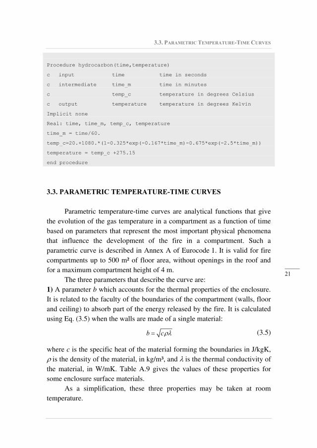
Example 3.2: Using the international system of units, write a procedure that
returns the value of the hydrocarbon time-temperature curve for a given
time.
_______________________________
3.3. PARAMETRIC TEMPERATURE-TIME CURVES
_____
21
Procedure hydrocarbon(time,temperature)
c input time time in seconds
c intermediate time_m time in minutes
c temp_c temperature in degrees Celsius
c output temperature temperature in degrees Kelvin
Implicit none
Real: time, time_m, temp_c, temperature
time_m = time/60.
temp_c=20.+1080.*(1-0.325*exp(-0.167*time_m)-0.675*exp(-2.5*time_m))
temperature = temp_c +275.15
end procedure
3.3. PARAMETRIC TEMPERATURE-TIME CURVES
Parametric temperature-time curves are analytical functions that give
the evolution of the gas temperature in a compartment as a function of time
based on parameters that represent the most important physical phenomena
that influence the development of the fire in a compartment. Such a
parametric curve is described in Annex A of Eurocode 1. It is valid for fire
compartments up to 500 m² of floor area, without openings in the roof and
for a maximum compartment height of 4 m.
The three parameters that describe the curve are:
1) A parameter b which accounts for the thermal properties of the enclosure.
It is related to the faculty of the boundaries of the compartment (walls, floor
and ceiling) to absorb part of the energy released by the fire. It is calculated
using Eq. (3.5) when the walls are made of a single material:
b c (3.5)
where c is the specific heat of the material forming the boundaries in J/kgK,
is the density of the material, in kg/m³, and is the thermal conductivity of
the material, in W/mK. Table A.9 gives the values of these properties for
some enclosure surface materials.
As a simplification, these three properties may be taken at room
temperature.
3. THERMAL ACTION
_____
22
When different parts of the walls, the floor or the ceiling are made
from different materials, a global value is calculated for the parameter b of
the compartment by factoring the value of each part with respect to its area
(openings not included), see Eq. (3.6).
i i
i
b Ab
A (3.6)
where bi is the value of the factor for part i and Ai is the area of part i, openings not included.
When a surface is made of different layers of material, only the value
b of the material of the innermost layer is considered, provided this value is
lower than the value of the second layer of material. If the b value of the
inner layer is higher than the b value of the second layer, then the b value of
the inner layer may be used if this layer is thick; if this layer is thin, the
influence of the second layer is also taken into account following the
procedure given by Eq. (A.4) in the Eurocode.
The parameter b should have a value between 100 and 2200 J/m²s1/2
K.
The parameter b is based on the theory of heat penetration by
conduction in a semi-infinite medium. In a wall made of two layers of
gypsum board separated by a cavity filled with air, for example, applying the
equations of the Eurocode with the values of c, and of the air would not
be correct because heat travels by radiation and not by conduction in the air
cavity. Similarly, it would not be correct to apply this model for a wall made
of a thin steel sheet, in an industrial building for example. This model would
be valid for steel only if the steel wall has infinite thickness, which is not
practical (furthermore b for steel is around 13400, which is in excess of the
admissible value of 2200).
2) A parameter O that accounts for the openings in the vertical walls. Higher
values of this parameter mean more ventilation for the compartment. The
value of this parameter has to be in the range 0.02 to 0.20 for the model of
the Eurocode to be applicable. If a single opening is present in the
compartment, the opening factor is calculated using Eq. (3.7). This equation
has been derived from the integration of the Bernoulli equation for a
pressure differential between the outside and the inside of the compartment
that varies linearly as a function of the vertical position.
v tO A h A (3.7)
3.3. PARAMETRIC TEMPERATURE-TIME CURVES
_____
23
where Av is the area of the opening, h is the height of the opening and At is
the total area of the enclosure (walls, ceiling and floor), including the
openings.
Eq. (3.7) shows that, for a given area, a vertically oriented opening is
more efficient in venting the compartment than a horizontally oriented
opening. When several openings are present in the compartment, the opening
factor is calculated from Eq. (3.8).
v eq tO A h A (3.8)
where Av is the total area of the vertical openings, heq is the averaged height
of the window openings, calculated from Eq. (3.9).
eq vi i v
i
h A h A (3.9)
3) The last parameter is the design fire load density related to the total area
of the enclosure: floor, ceiling and walls, openings included. Annex E of
Eurocode 1 allows the design value to be determined from the floor area on
the basis of the type of occupation of the compartment and the presence of
active fire protection measures. Both values are related by Eq. (3.10).
, ,t d f d f tq q A A (3.10)
where qt,d is the design value of the fire load density related to the total area
of enclosure, qf,d is the design value of the fire load density related to the
floor area, Af is the floor area and At is the total area of the enclosure.
The model is valid for values of qt,d between 50 and 1000 MJ/m².
Application of the model starts by calculating an expansion coefficient
from Eq. (3.11).
2
0.04
1160
O
b (3.11)
The evolution of temperature during the heating phase is given by
Eq. (3.12) as a function of an expanded time *t given by Eq. (3.13).
* * *0.2 1.7 1920 1325 1 0.324 0.204 0.472t t t
g e e e (3.12)
*t t (3.13)
3. THERMAL ACTION
_____
24
where t is the time in hours.
The curve that can be plot from Eq. (3.12) as a function of *t is very
close to the standard temperature-time curve. Eq. (3.13) shows that, when
is greater than 1, the temperature increase as a function of the real time t is
faster than for lower values of .
The duration of the heating phase tmax is given, in hours, by Eq. (3.14).
max ,0.0002 t dt q O (3.14)
This value has to be compared with a limit value tlim that depends on
the growth rate associated to the occupancy of the compartment, see
Table (3.1).
Table 3.1: Values of tlim as a function of the growth rate
Growth rate tlim in minutes tlim in hours
Slow (transport (public space) ) 25 0.417
Medium (dwelling, hospital room, hotel
room, office, classroom of a school)
20 0.333
Fast (library, shopping centre,
theatre/cinema )
15 0.250
The comparison between the value calculated for tmax and the value of
tlim can lead to two different situations:
Either tmax tlim and the fire is ventilation controlled. The procedure for
this situation is explained below.
The value of the gas temperature at the end of the heating phase, max, is
calculated by substituting the value of tmax for t in Eq. (3.13) and (3.12).
The expanded time that corresponds to the maximum time is calculated
from Eq. (3.15). *
max maxt t (3.15)
The time temperature in the cooling phase is given by:
* *
max max625g t t for *
max 0.5t (3.16a)
* * *
max max max250 3g t t t for *
max0.5 2.0t (3.16b)
* *
max max250g t t for *
max2.0 t (3.16c)
3.3. PARAMETRIC TEMPERATURE-TIME CURVES
_____
25
Or tmax < tlim and the fire is fuel controlled. The procedure for this
situation is explained below:
Eq. (3.17) is used instead of Eq. (3.13) to compute the evolution of the
temperature during the heating phase. *
limt t (3.17)
with
2
limlim
0.04
1160
O
b (3.18)
and
lim , lim0.0001 t dO q t (3.19)
If O > 0.04 and qt,d < 75 and b < 1160, then lim in Eq. (3.18) has to be
multiplied for the factor k given by Eq. (3.20).
, 750.04 11601
0.04 75 1160
t dqO bk (3.20)
The expanded time that corresponds to the time of maximum
temperature is calculated from Eq. (3.21).
*
max lim limt t (3.21)
The value of the gas temperature at the end of the heating phase, max, is
calculated by substituting the value of t*max for t*
in Eq. (3.12).
The time temperature in the cooling phase is given by: *
max lim625g t t for *
max 0.5t (3.22a)
* *
max max lim250 3g t t t for *
max0.5 2.0t (3.22b)
*
max lim250g t t for *
max2.0 t (3.22c)
When applying Eq. (3.22), t* and t*max are calculated from Eqs. (3.13)
and (3.15), and not from Eqs. (3.17) and (3.21).
It has to be noted that there is a discontinuity in the model at the
transition from a fuel controlled fire to a ventilation controlled fire, because
of different factors present in Eq. (3.14) and Eq. (3.19). An infinitely small
variation of a parameter can produce two time-temperature curves that are
3. THERMAL ACTION
_____
26
not close to each other. In other words, when tmax is exactly equal to tlim, the
equations for a ventilation controlled fire lead to a fire curve that is different
from the one obtained by the equations of a fuel controlled fire.
When a parametric fire model is used, the heat flux at the surface of a
steel member is calculated from Eq. (3.4) with a coefficient of convection c
equal to 35 W/m²K.
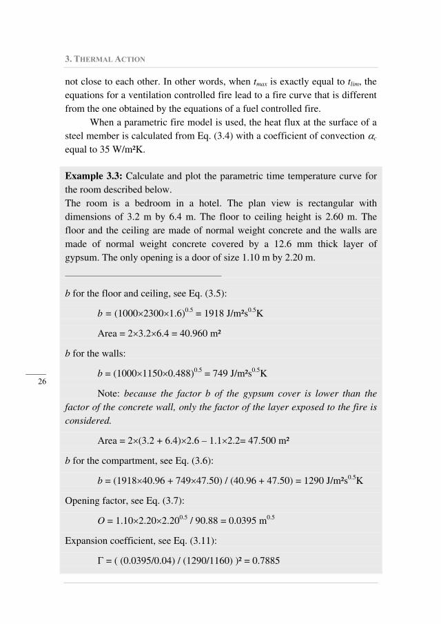
Example 3.3: Calculate and plot the parametric time temperature curve for
the room described below.
The room is a bedroom in a hotel. The plan view is rectangular with
dimensions of 3.2 m by 6.4 m. The floor to ceiling height is 2.60 m. The
floor and the ceiling are made of normal weight concrete and the walls are
made of normal weight concrete covered by a 12.6 mm thick layer of
gypsum. The only opening is a door of size 1.10 m by 2.20 m.
_______________________________
b for the floor and ceiling, see Eq. (3.5):
b = (1000 2300 1.6)0.5
= 1918 J/m²s0.5
K
Area = 2 3.2 6.4 = 40.960 m²
b for the walls:
b = (1000 1150 0.488)0.5
= 749 J/m²s0.5
K
Note: because the factor b of the gypsum cover is lower than the factor of the concrete wall, only the factor of the layer exposed to the fire is considered.
Area = 2 (3.2 + 6.4) 2.6 – 1.1 2.2= 47.500 m²
b for the compartment, see Eq. (3.6):
b = (1918 40.96 + 749 47.50) / (40.96 + 47.50) = 1290 J/m²s0.5
K
Opening factor, see Eq. (3.7):
O = 1.10 2.20 2.200.5
/ 90.88 = 0.0395 m0.5
Expansion coefficient, see Eq. (3.11):
= ( (0.0395/0.04) / (1290/1160) )² = 0.7885
3.3. PARAMETRIC TEMPERATURE-TIME CURVES
_____
27
Note: a value of lower than 1.0 means that the fire curve will increase more slowly than the standard time temperature curve.
Design fire load, see Eq. (3.10): table E.4 of Eurocode 1 gives for hotels a
value of qf,k equal to 377 MJ/m². Assuming that the influence of active
measures is not taken into account, this leads to qf,d = qf,k = 377 MJ/m².
qt,d = 377 (3.2 6.4) / 90.88 = 84.96 MJ/m²
Duration of the heating phase, see Eq. (3.14):
tmax = 0.0002 84.96 / 0.0395 = 0.43 hour (26 min.).
Limit value of time, see table 3.1:
tlim = 0.333 hour
Because tlim < tmax, the fire is ventilation controlled.
Temperature at the end of the heating phase, see Eqs. (3.15) and (3.12):
t*max = 0.7885 0.43 = 0.339 hour
0.2 0.339 1.7 0.339 19 0.339
max 20 1325 1 0.324 0.204 0.472e e e
max = 791°C.
Time at the end of the cooling phase, see Eq. (3.16a):
t*20 = (791 - 20) / 625 + 0.339 = 1.573 hours
t20 = 1.573/0.7885 = 1.995 hours (120 min.)
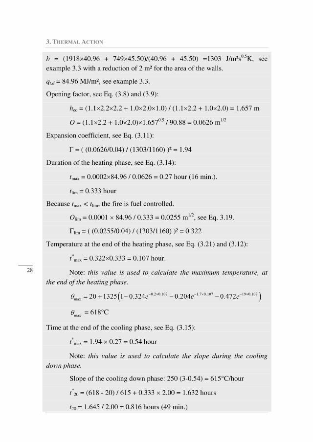
The complete time temperature curve is show as a continuous line in
Fig. 3.2.
_____________________________________________________________
Example 3.4: Calculate and plot the parametric time temperature for the
room of example 3.3 if, in addition to the door, a window (2 m wide and 1 m
high) is also open.
_______________________________
3. THERMAL ACTION
_____
28
b = (1918 40.96 + 749 45.50)/(40.96 + 45.50) =1303 J/m²s0.5
K, see
example 3.3 with a reduction of 2 m² for the area of the walls. qt,d = 84.96 MJ/m², see example 3.3. Opening factor, see Eq. (3.8) and (3.9):
heq = (1.1 2.2 2.2 + 1.0 2.0 1.0) / (1.1 2.2 + 1.0 2.0) = 1.657 m
O = (1.1 2.2 + 1.0 2.0) 1.6570.5
/ 90.88 = 0.0626 m1/2
Expansion coefficient, see Eq. (3.11):
= ( (0.0626/0.04) / (1303/1160) )² = 1.94 Duration of the heating phase, see Eq. (3.14):
tmax = 0.0002 84.96 / 0.0626 = 0.27 hour (16 min.).
tlim = 0.333 hour Because tmax < tlim, the fire is fuel controlled.
Olim = 0.0001 84.96 / 0.333 = 0.0255 m1/2
, see Eq. 3.19.
lim = ( (0.0255/0.04) / (1303/1160) )² = 0.322 Temperature at the end of the heating phase, see Eq. (3.21) and (3.12):
t*max = 0.322 0.333 = 0.107 hour.
Note: this value is used to calculate the maximum temperature, at the end of the heating phase.
0.2 0.107 1.7 0.107 19 0.107
max 20 1325 1 0.324 0.204 0.472e e e
max = 618°C
Time at the end of the cooling phase, see Eq. (3.15):
t*max = 1.94 0.27 = 0.54 hour
Note: this value is used to calculate the slope during the cooling down phase. Slope of the cooling down phase: 250 (3-0.54) = 615°C/hour
t*20 = (618 - 20) / 615 + 0.333 2.00 = 1.632 hours
t20 = 1.645 / 2.00 = 0.816 hours (49 min.)
3.4. ZONE MODELS
_____
29
The complete time temperature curve is show as a dotted line in Fig. 3.2.
0
100
200
300
400
500
600
700
800
900
0 30 60 90 120 150Time [min.]
Te
mp
era
ture
[°C
]
Example 3.3
Example 3.4
Fig. 3.2: Examples of parametric time-temperature curves
3.4. ZONE MODELS
Zone models are models that can be used to compute the development
of the temperature in the fire compartment1 on the basis of differential
equations expressing mass balance and energy balance equilibrium.
The main parameters that influence the development of the
temperature are the same as those for the parametric fire models.
The openings in the boundaries play a crucial role because they
provide the air that feeds the fire and because they can vent the
compartment. But, whereas all the openings are represented by a single
lumped parameter O in the parametric model, each individual opening can
be represented in a zone model with its own dimensions and position.
Openings in the walls as well as in the ceiling can be taken into account.
Some may be closed at the beginning of the fire and opened at a given time
(human intervention) or at a given temperature criteria (braking of the
windows). Forced ventilation can also be considered if needed.
1 And, for multiroom models, also in the adjacent compartments.
3. THERMAL ACTION
_____
30
The energy absorbed by the walls is also important but, whereas all the
boundaries of the compartment are represented by a lumped parameter b and
the heat penetration theory in semi-infinite media is used in the parametric
model, each wall can be represented individually in a zone model, each with
all the different layers that may be present. The energy absorbed by the
boundaries can be calculated precisely on the basis of the heat absorbed and
transmitted to the exterior of the compartment by conduction and radiation in
cavities when relevant.
The amount of fuel q present in the compartment is of course of
primary importance. For a zone model, not only the total quantity present in
the compartment must be given as a data but also the rate at which it will be
released (Rate of Heat Release, RHR) as well as the associated mass loss rate
(pyrolysis rate). The user can find some guidance on these rates in
Annex E.4 of Eurocode 1. If the pyrolysis rate and/or the RHR introduced by
the user are at any time higher than those that the openings can
accommodate, the zone model can detect this situation and modify the data
accordingly, either by a modification of the pyrolysis rate (and the duration
of the fire is extended) or by a modification of the RHR (corresponding to
some part of the combustion taking place outside of the compartment). Zone
models don’t have any prescribed shape embedded for the time temperature
curve, as is the case for the parametric models. The shape of the time
temperature curve is different for each case, although it is strongly linked to
the shape of the RHR curve that has been introduced.
Such models are called “zone models” because the compartment is
divided into one or several zones in which the situation is assumed to be
uniform. The most commonly used models are one zone models where the
whole compartment consist of one single zone and two zone models in which
a lower zone comprises cold and clean air and an upper zone contains hot
combustion products. One zone models represent a post-flash-over situation
whereas two zone models represent a pre-flash-over situation. Some models
may start in a two zone situation and shift automatically to a one zone
situation when some predefined criteria are met. More refined models can
distinguish zones at a more detailed level such as, for example, the plume or
the ceiling jet, but such models are not envisaged in Eurocode 1.
Eurocode 1 gives very few recommendations on zone models except
that gas properties, mass exchanges and energy exchanges should be
considered and that an iterative procedure is involved. This means that the
3.5. CFD MODELS
_____
31
differential equations have to be integrated with time to yield the
time-temperature curve. This can not be done by hand and computer
software is required. Several computer programs are available and two zone
models produced by research institutions can be downloaded for free,
namely CFAST from NIST in the U.S.A. and OZone from the University of
Liege in Belgium.
When the steel member is located in the hot zone of a two zone model,
or when it is located in a compartment modelled by a one zone model, the
heat flux at the surface is calculated from Eq. (3.4) with a coefficient of
convection c equal to 35 W/m²K.
When a steel member is located in the lower and cold zone of a two
zone model, heat transfer is by convection with the air of the cold zone, but
radiation from different surfaces should theoretically also be considered, for
example, from the separation plane with the upper zone, from the floor and
parts of the walls that are in the cold zone and from the fire plume. The
evaluation of the temperature of steel members located in the cold zone is
usually not performed because the temperatures are not normally significant
for structural steel elements located in that zone. An exception to this is
when the steel members are close enough to the fire source that the effect of
heat transfer from the source is significant. Localised fire models allow this
effect to be considered, see Section 3.6.
3.5. CFD MODELS
CFD models have become more and more popular in fire safety
engineering in the last decade. CFD stands for Computational Fluid Dynamics. Such models rely on a division of the compartment into a very
high number of cells in which the Navier-Stokes equations are written and
solved. Such models produce a large number of results at a very detailed
level, for example, pressure, temperature, velocity, chemical components
and optical obstruction in every cell. Application of such models requires
specific software, powerful computers and well educated and highly
experienced users. They are mentioned in Eurocode 1 without any
recommendation. A detailed description of such models is beyond the scope
of this design guide.
3. THERMAL ACTION
_____
32
3.6. LOCALISED FIRES
Except in very exceptional circumstances, every fire in a building
starts as a small localised fire. The fire ceases to be localised when
flash-over occurs. Even a localised fire may have a significant impact on a
structure, depending on the type of structure and relative position of the fire
with respect to the structural elements.
Eurocode 1 states that thermal actions of a localised fire should be
taken into account “where flash-over is unlikely to occur”. Apart from the
fact that the term unlikely is vague and cannot be transformed into an
operational recommendation, this sentence is misleading. For example, a
localised fire near a main column in an airport hall may lead to the collapse
of the column and, perhaps, of the whole buildings. Although flash-over is
unlikely to occur in such a big hall, does this mean that this action can be
ignored? Probably not. More correctly the wording of the sentence should
say “when the flash-over has not yet occurred”. This means that localised
fires can be ignored if the fire model is a post-flash-over model such as for
nominal time-temperature fire curves and one zone models. Effects of a
localised fire are automatically taken into account in a CFD model, at least
during the first stage of the fire. In a two zone model, effects of the localised
fire should be considered, at least as long as the flash-over has not occurred.
In that case, Eurocode 1 explicitly recommends that the maximum between
the effect of the localised fire and the effect of the hot zone be considered.
Two models are presented in Annex C of Eurocode 1 for the effects of
a localised fire. Which one has to be used depends on the vertical length of
the flame that would develop in the absence of any ceiling. This length Lf is
evaluated from Eq. (3.23)
0.40.0148 1.02fL Q D (3.23)
where D is the diameter of the fire and Q is the rate of heat release of the fire
according to Annex E.4.
Example 3.5: What is the flame length of a localised fire in a shopping
centre 5 minutes after the start of the fire?
_______________________________
3.6. LOCALISED FIRES
_____
33
Table E.5 recommends a fast fire for a shopping centre, with a time constant
t of 150 seconds. Eq. (E.5) of Eurocode 1 yields:
Q = 106 (5×60/150)² = 4 MW.
The same table recommends a heat release rate density of 250 kW/m².
The fire surface required to release a power of 4 MW is thus given by:
Afire = 4 / 0.25 =16 m².
Assuming a circular shape of the fire yields a diameter:
D = (4×16 / )0.5
= 4.514 m
The length of the flame is thus calculated from Eq. (3.23)
Lf = 0.0148× (4×106)
0.4 – 1.02×4.514 = 1.869 m
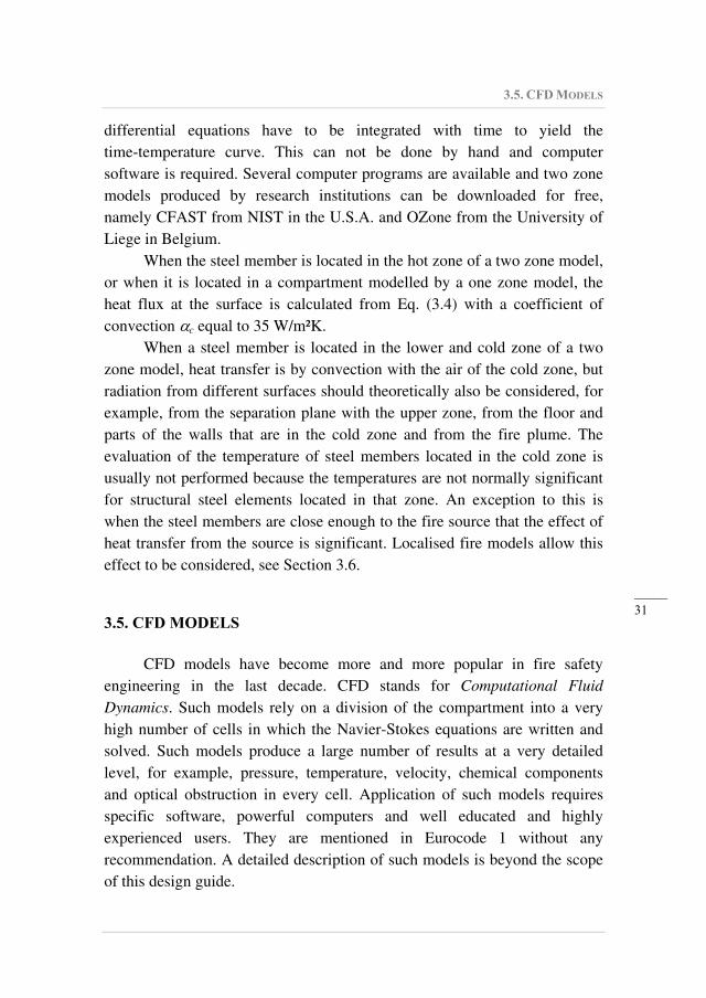
Fig. 3.3, taken from Annex C of Eurocode 1, shows the length of the
flame Lf when the fire source is on the floor and the flame does not impact
the ceiling. Depending on the particular situation, the vertical location of the
fire source might be at a higher level than the floor level. The Eurocode says
that the flame does not impact the ceiling when Lf < H, but this condition
must be modified when the fire source is not located on the floor. In that
case, H has to be understood as the vertical distance from the fire source to
the ceiling.
Fig. 3.3: Flame on the floor and not impacting the ceiling
When the flame is not impacting the ceiling or if the fire is in the open
air, the temperature (z) in the plume along the symmetrical vertical flame
axis is given by Eq. (3.24).
3. THERMAL ACTION
_____
34
2 5
3 320 0.25 900c OzQ z z (3.24)
where Qc is the convective part of the rate of heat release [W], taken as 0.8 Q
by default, z is the height along the flame axis from the position of the
source [m] and z0 is the virtual origin of the fire source, calculated from Eq.
(3.25).
0.4
0 0.00524 1.02z Q D (3.25)
The net heat flux neth received by the surface of a structural member
from the fire source should be calculated from Eq. (3.26), see Section 3.1 in
Eurocode 1.
4 4273 273net c g m m f r mh (3.26)
where c is the coefficient of convection taken here as 35 W/m²K, g is the
gas temperature in the vicinity of the surface either calculated from
Eq. (3.24) if the surface is in the fire plume or taken as 20°C if the surface is
in air at ambient temperature1, m is the surface temperature of the member
or of the thermal protection material, is a configuration factor to be
calculated using Annex G of Eurocode 1, m is the surface emissivity of the
member taken as 0.7 for carbon steel, 0.4 for stainless steel and 0.8 for other
materials, f is the emissivity of the fire, in general taken as 1.02, is the
Stephan Boltzmann constant equal to 5.67 10-8 W/m²K
4 and r is the
radiation temperature of the fire environment.
To apply Eq. (3.26), the second term of the right-hand part, taking
radiation into account, should be split in a spatial integration on the
hemisphere normal to the surface, with different view factors considered for
parts of the solid angle that don't comprise the fire plume (and where r
should be taken as 20°C) and for parts of the solid angle that comprise the
fire plume (where r should be calculated from Eq. (3.24)). A hypothesis has
thus to be made on the shape of the fire plume, for example, cylindrical or
conical. The solid angle that encompasses the plume should itself be divided
1 That means, out of the plume and out of the eventual hot zone when the model is
combined with a zone model. 2 Eq. (B.16) of Annex B of Eurocode 1 could be used and yield an emissivity lower
than 1.0 if the flame is thin (when D is small).
3.6. LOCALISED FIRES
_____
35
into several vertical slices, because the temperature of the flame varies with
elevation. The section of the steel member itself must be divided into several
surfaces, each with a different orientation, some facing the fire, some not
seeing the fire, and some seeing it only partially. Practical application of the
model can quickly become complex.
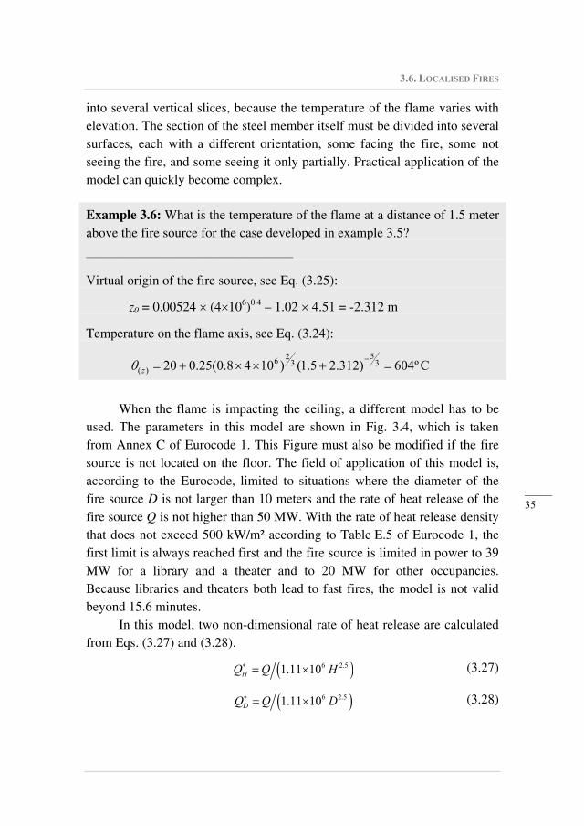
Example 3.6: What is the temperature of the flame at a distance of 1.5 meter
above the fire source for the case developed in example 3.5?
_______________________________
Virtual origin of the fire source, see Eq. (3.25):
z0 = 0.00524 (4 106)
0.4 – 1.02 4.51 = -2.312 m
Temperature on the flame axis, see Eq. (3.24):
Cº604)312.25.1()1048.0(25.020 35
32
6)( z
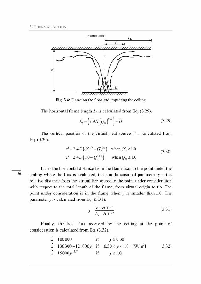
When the flame is impacting the ceiling, a different model has to be
used. The parameters in this model are shown in Fig. 3.4, which is taken
from Annex C of Eurocode 1. This Figure must also be modified if the fire
source is not located on the floor. The field of application of this model is,
according to the Eurocode, limited to situations where the diameter of the
fire source D is not larger than 10 meters and the rate of heat release of the
fire source Q is not higher than 50 MW. With the rate of heat release density
that does not exceed 500 kW/m² according to Table E.5 of Eurocode 1, the
first limit is always reached first and the fire source is limited in power to 39
MW for a library and a theater and to 20 MW for other occupancies.
Because libraries and theaters both lead to fast fires, the model is not valid
beyond 15.6 minutes.
In this model, two non-dimensional rate of heat release are calculated
from Eqs. (3.27) and (3.28).
6 2.51.11 10HQ Q H (3.27)
6 2.51.11 10DQ Q D (3.28)
3. THERMAL ACTION
_____
36
Fig. 3.4: Flame on the floor and impacting the ceiling
The horizontal flame length Lh is calculated from Eq. (3.29).
0.33
2.9h HL H Q H (3.29)
The vertical position of the virtual heat source z' is calculated from
Eq. (3.30).
2 5 2 3
2 5
' 2.4 when 1.0
' 2.4 1.0 when 1.0
D D D
D D
z D Q Q Q
z D Q Q
(3.30)
If r is the horizontal distance from the flame axis to the point under the
ceiling where the flux is evaluated, the non-dimensional parameter y is the
relative distance from the virtual fire source to the point under consideration
with respect to the total length of the flame, from virtual origin to tip. The
point under consideration is in the flame when y is smaller than 1.0. The
parameter y is calculated from Eq. (3.31).
'
'h
r H zy
L H z (3.31)
Finally, the heat flux received by the ceiling at the point of
consideration is calculated from Eq. (3.32).
1.0if00015
1.00.30if000121300136
0.30if000100
73 yyh
yyh
yh
.
[W/m2] (3.32)
3.6. LOCALISED FIRES
_____
37
Because Eq. (3.32) only gives the flux received at the surface, the net
heat flux has to be calculated from Eq. (3.33).
4 420 273 293net c m m f mh h (3.33)
This equation verifies the condition that, when the impinging flux h is
equal to 0, a temperature of the member m of 20°C will lead to a situation
where the net flux received at the surface neth is equal to 0.
It also shows that, when the impinging flux is constant for a long
period, the temperature of the member tends toward an equilibrium
temperature (corresponding to neth = 0) that is directly linked to the value of
the impinging flux. With a coefficient of convection c equal to 35 W/m²K
and an emissivity of steel equal to 0.7 (emissivity of the flame and
configuration factor equal to 1.0) the temperature of a steel member cannot
exceed 880°C for an impinging flux that cannot exceed 100 kW/m2, see
Eq. (3.32).
In the experimental tests that are at the basis of this model, the
fluxmeters were located at ceiling level. This is the location for which
Eq. (3.32) gives the received flux. For a steel element, say a steel beam,
located under the ceiling, not all surfaces are located at the level of the
ceiling. The level that should be considered when applying the model is not
given in the Eurocode. For a section located just above the fire source,
considering each surface with its own level, or assuming that all surfaces
have the same level as the lower flange, are probably on the safe side. For a
section located far away from the fire source, the model is theoretically only
applicable for surfaces located at the level of the ceiling. Considering the
flux received at that level for all surfaces of the section is probably on the
safe side in this case, because the flame is normally constrained under the
ceiling. If the depth of the beam is relatively small compared to the fire
source to ceiling distance, then it may be reasonable to consider the level of
the axis of the beam for all surfaces in all sections. Engineering judgement is
required here.
Example 3.7: What is the maximum flux received at the level of the ceiling
in a library 15 minutes after the start of the fire if the vertical distance from
the fire source to the ceiling is 3 meters?
3. THERMAL ACTION
_____
38
_______________________________
Table E.5 recommends a fast fire for a library, with a time constant t of
150 seconds. Eq. (E.5) of Eurocode 1 yields:
Q = 106 (15×60/150)² = 36 MW.
The same table recommends a rate of heat release rate density of 500 kW/m².
The fire surface required to release a power of 36 MW is thus given by:
Afire = 36 / 0.50 = 72 m².
Assuming a circular shape of the fire yields a diameter:
D = (4×72 / )0.5
= 9.58 m
The length of the flame is thus calculated from Eq. (3.23)
Lf = 0.0148× (36×106)
0.4 – 1.02×9.58 = 5.816 m
Because this length is higher than the source to ceiling distance, the second
model has to be used.
HQ = 36×106/(1.11×10
6 × 3
2.5) = 2.081
DQ = 36×106/(1.11×10
6 × 9.58
2.5) = 0.114
Horizontal flame length, see Eq. (3.29).
Lh = 2.9 × 3 × 2.0810.33
– 3 = 8.080 m
Virtual position of the fire source, see Eq. (3.30)
z’ = 2.4 × 9.58 (0.1142/5
-0.1142/3
) = 4.24 m.
The maximum flux occurs just above the fire source, where r = 0. At this
location, the parameter y is calculated from Eq. (3.31).
y = (3+4.24)/(8.080+3+4.24) = 0.473
The heat flux received is given by Eq. (3.32)
h = 136.3 – 121 × 0.473 = 79.1 kW/m²
_____________________________________________________________
3.7. EXTERNAL MEMBERS
_____
39
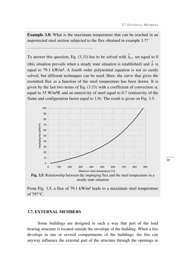
Example 3.8: What is the maximum temperature that can be reached in an
unprotected steel section subjected to the flux obtained in example 3.7?
_______________________________
To answer this question, Eq. (3.33) has to be solved with neth set equal to 0
(this situation prevails when a steady state situation is established) and h is
equal to 79.1 kW/m². A fourth order polynomial equation is not so easily
solved, but different techniques can be used. Here, the curve that gives the
reemitted flux as a function of the steel temperature has been drawn. It is
given by the last two terms of Eq. (3.33) with a coefficient of convection c
equal to 35 W/m²K and an emissivity of steel equal to 0.7 (emissivity of the
flame and configuration factor equal to 1.0). The result is given on Fig. 3.5.
0
10
20
30
40
50
60
70
80
90
100
0 100 200 300 400 500 600 700 800 900
Maximum steel temperature [°C]
Impin
gin
g f
lux [
kW
/m²]
Fig. 3.5: Relationship between the impinging flux and the steel temperature in a
steady state situation From Fig. 3.5, a flux of 79.1 kW/m² leads to a maximum steel temperature
of 797°C.
3.7. EXTERNAL MEMBERS
Some buildings are designed in such a way that part of the load
bearing structure is located outside the envelope of the building. When a fire
develops in one or several compartments of the buildings, the fire can
anyway influence the external part of the structure through the openings in
3. THERMAL ACTION
_____
40
the envelope (mainly the windows).
Annex B of Eurocode 1 gives a method for determining the radiation
and convection parameters that can be used in a thermal analysis for
calculating the temperature in the external elements. To calculate the
radiation and convection parameters, the maximum temperature of the
compartment fire as well as the size and temperature of the flames from the
openings are first calculated.
The model assumes a steady state situation of a fully developed fire in
the compartment, and the pre-flash-over phase and the cooling down phase
of the fire are neglected.
The method is valid only for fire loads qf,d higher than 200 MJ per
square meter of floor area and the size of the compartment should not exceed
70 m in length, 18 m in width and 5 m in height.
Application of the method starts by evaluating the ratio D/W which
depends on the number of walls that contain windows, the number of
windows in the relevant wall and the presence of a core in the compartment.
Reference is made in the Eurocode to wall 1 as the wall assumed to contain
the greatest window area. It is likely that, if a compartment has openings in
several walls, the method should be applied successively for each wall with
wall 1 being, in each case, the wall that is relevant for the external structural
element under consideration.
If there are windows only in wall 1 and there is no core in the fire
compartment, the ratio D/W is calculated from Eq. (3.34).
1
2/w
WWD (3.34)
where W2 is the width of the wall perpendicular to wall 1 in the fire
compartment (i.e., the size of the fire compartment perpendicular to wall 1),
and w1 is the width of wall 1.
Other equations are proposed if windows are present in several walls
or if there is a core in the fire compartment. All parts of an external wall that
don't have the fire resistance (REI) required for the stability of the building
have to be considered as windows. If the total window area in a wall exceeds
50% of the area of the wall, two subsequent calculations have to be made,
first with the total window area and then with only half of the total window
area being active (window panes broken). The location of the active part of
the windows must be chosen as the most severe for the structural elements.
3.7. EXTERNAL MEMBERS
_____
41
The wind has two effects on the model. First, the flames can leave the
fire compartment through the windows either perpendicular to the façade or
at a horizontal angle of 45° to the façade. A strict interpretation of this
recommendation means that three different directions should be considered
for the flames from the opening: -45°, 0° and +45°. Second, if there are
openings on opposite sides of the fire compartment, the calculation shall be
made in forced draught conditions. This is also the case if additional air is
being fed in the compartment from another source (other than the windows),
but this situation is not common.
If there is no forced draught, the rate of heat release in the
compartment is given by Eq. (3.35).
, 0.036min ;3.15 1f f d eqO
v
F
A q hQ e A
D W (3.35)
where F is the free burning duration assumed to be equal to 1200 seconds1.
The first term in the parenthesis of Eq. (3.35) represents a fuel
controlled situation whereas the second term represents a ventilation
controlled situation.
The steady state temperature of the fire compartment is given by
Eq. (3.36).
0.1 0.00286
06000 1 1O
fT e O e T (3.36)
where
,f f d
v t
A q
A A (3.37)
and the opening factor O is given by Eq. (3.8).
The flame exits through the upper 2/3 of the window height whereas
fresh air flows into the compartment through the lower 1/3. From the
window, the width of the flame is not modified; it remains equal to the
window width.
On exiting the window, the flame is deflected upward and, from the
top of the window, the thickness of the flame perpendicular to the wall is
equal to 2/3 of the window height whereas the flame height (i.e., the vertical
extension of the flame above the top of the window), is given by Eq. (3.38).
1 Note the similarity with tlim used in the parametric fire model.
3. THERMAL ACTION
_____
42
23
1.9L eq
t
QL h
w (3.38)
Other expressions are used to calculate LH, the horizontal distance
from the wall to the centerline of the flame at the top of the flame. The
geometrical shape of the flame is thus fully defined. The flame trajectory
may be deflected by the presence of balconies and awnings and Eurocode 1
gives modified equations for these cases.
The flame temperature at the window is given by Eq. (3.39).
0520 1 0.4725W f tT L w Q T (3.39)
with f tL w Q < 1.
The emissivity of the flames at the window may be taken as f = 1.0.
The temperature of the flame along the axis at a distance Lx from the
window is given by Eq. (3.40).
0 01 0.4725Z W X tT T T L w Q T (3.40)
with X tL w Q < 1.
The emissivity of the flame may be calculated from Eq. (3.41).
0.3
1 fd
f e (3.41)
where df is the flame thickness.
The convective heat transfer coefficient is given by Eq. (3.42).
0.60.44.67c eq vd Q A (3.42)
where deq is the characteristic size of the structural member, for example, its
diameter or width.
Some equations are given for the configuration factors between an
opening or a flame (assumed to be rectangular in shape) and the side of a
member.
Annex G gives the equations for calculating the configuration factor
from a radiating surface to a receiving surface. The configuration factor is
calculated at the center P of each surface of the structural member.
3.7. EXTERNAL MEMBERS
_____
43
When the radiating surface and the receiving surface are parallel, a
perpendicular line is drawn from point P to the radiating surface that it
intersects at point X, see Fig. 3.6 taken from Eurocode 1. The radiating
surface is then divided into 4 rectangular surfaces, each one having its own
height h and width w. Equation G.2 given in the Eurocode is in fact valid for
a radiating surface that has the intersection point X at one of its corners. This
equation has thus to be applied 4 times, once for each rectangle, and the sum
of the 4 contributions yields the configuration factor between the radiating
surface and the receiving surface.
When the radiating surface and the receiving surface are
perpendicular, a perpendicular line is drawn from point P to the radiating
surface which it intersects at point X, see Fig. 3.7 which is taken from
Eurocode 1. If part of the radiating surface cannot "see" the receiving
surface, this part does not contribute to the radiating factor. The contributing
part of the radiating surface is then divided into two rectangular surfaces,
each one having its own height h and width w. Equation G.3 given in the
Eurocode is valid for a radiating surface that has the intersection point X at
one of its corners. This equation has to be applied twice, once for each
rectangle, and the sum of the two contributions yields the configuration
factor between the radiating surface and the receiving surface.
Fig. 3.6: Configuration factor for two parallel surfaces
3. THERMAL ACTION
_____
44
Fig. 3.7: Configuration factor for two perpendicular surfaces
If the intersection point X is outside the radiating surface, the radiating
surface must be extended to the Point X and some negative contributions
must be taken into account, see Fig. 3.8.
Fig. 3.8: Configuration factor when point P is outside the radiating surface
When the configuration factor has been calculated for the four faces of
a structural member, the overall configuration factor can be calculated from
Eq. (3.43). This equation can be applied whether the radiating surface is a
window or a flame.
4
1
4
1
i i ii
i ii
C d
C d
(3.43)
where Ci is equal to 0 for a thermally protected face and equal to 1
otherwise, i is the configuration factor of face i and di is the cross-
sectional dimension of face i.
X X X
= -