Embed Size (px)
Citation preview
1 of 9Publication part number A9900488 issue 4, ADC 12976© Triumph Designs Ltd. 2013
English
Fitting Instructions:Tiger Explorer and Tiger Explorer XCA9638086, A9638048 and A9638121Thank you for choosing this Triumph genuine accessory kit. This accessory kit is the product of Triumph's use of provenengineering, exhaustive testing, and continuous striving for superior reliability, safety and performance.
Completely read all of these instructions before commencing the installation of the accessory kit in order to becomethoroughly familiar with the kit’s features and the installation process.
These instructions should be considered a permanent part of your accessory kit, and should remain with it even if youraccessory-equipped motorcycle is subsequently sold.
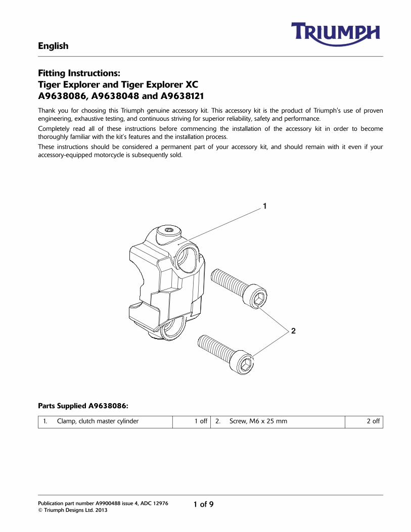
Parts Supplied A9638086:
1. Clamp, clutch master cylinder 1 off 2. Screw, M6 x 25 mm 2 off
1
2
2 of 9
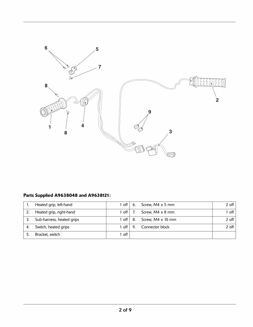
Parts Supplied A9638048 and A9638121:
1. Heated grip, left-hand 1 off 6. Screw, M4 x 5 mm 2 off
2. Heated grip, right-hand 1 off 7. Screw, M4 x 8 mm 1 off
3. Sub-harness, heated grips 1 off 8. Screw, M4 x 10 mm 2 off
4. Switch, heated grips 1 off 9. Connector block 2 off
5. Bracket, switch 1 off
1
2
34
56
7
8
8
9
3 of 9
Heated Grip Installation
1. Remove the rider’s seat, refer to the owner’s manual.
2. Disconnect the battery, negative (black) lead first.
3. Remove the following items as described in the servicemanual:
• Fuel tank;
• Handlebar end weights;
• Left-hand switch cube;
• Left-hand handlebar grip.
4. Remove the right-hand switch cube screws andposition the rear of the switch cube away from thehandlebar.
Note:
• To gain access to the switch cube screws it maybe necessary to slacken the front brake mastercylinder clamp screws and rotate the assemblyout of the way.
Note:
• Note the position and orientation of the twistgrip to the switch cube for installation.
WarningThis accessory kit is designed for use on TriumphTiger Explorer and Tiger Explorer XC motorcycles onlyand should not be fitted to any other Triumph model or toany other manufacturer's motorcycle. Fitting this accessorykit to any other Triumph model or to any othermanufacturer's motorcycle will affect the performance,stability and handling of the motorcycle. This may affectthe rider's ability to control the motorcycle and couldcause an accident.
WarningAlways have Triumph approved parts, accessories andconversions fitted by a trained technician of an authorisedTriumph dealer. The fitment of parts, accessories andconversions by a technician who is not of an authorisedTriumph dealer may affect the handling, stability or otheraspects of the motorcycle’s operation which may result inloss of motorcycle control and an accident.
WarningAlways ensure that the newly installed wiring does notchafe against other parts of the motorcycle such that itmay be rubbed through and cause an electrical problem.In addition, always ensure that the newly installed wiringwill not restrict steering movement. Both conditions arehazardous and could give rise to a dangerous ridingcondition resulting in a fire, loss of motorcycle control andan accident.
WarningThroughout this operation, ensure that the motorcycle isstabilised and adequately supported to prevent risk ofinjury from the motorcycle falling.
WarningA torque wrench of known accurate calibration must beused when fitting this accessory kit. Failure to tighten anyof the fasteners to the correct torque specification mayaffect motorcycle performance, handling and stability. Thismay result in loss of motorcycle control and an accident.
WarningDo not allow the master cylinder to invert as this willintroduce air into the brake system and may also causebrake fluid to leak resulting in damage to bodywork.
A dangerous riding condition, leading to loss ofmotorcycle control and an accident could result if thiswarning is ignored.
4 of 9
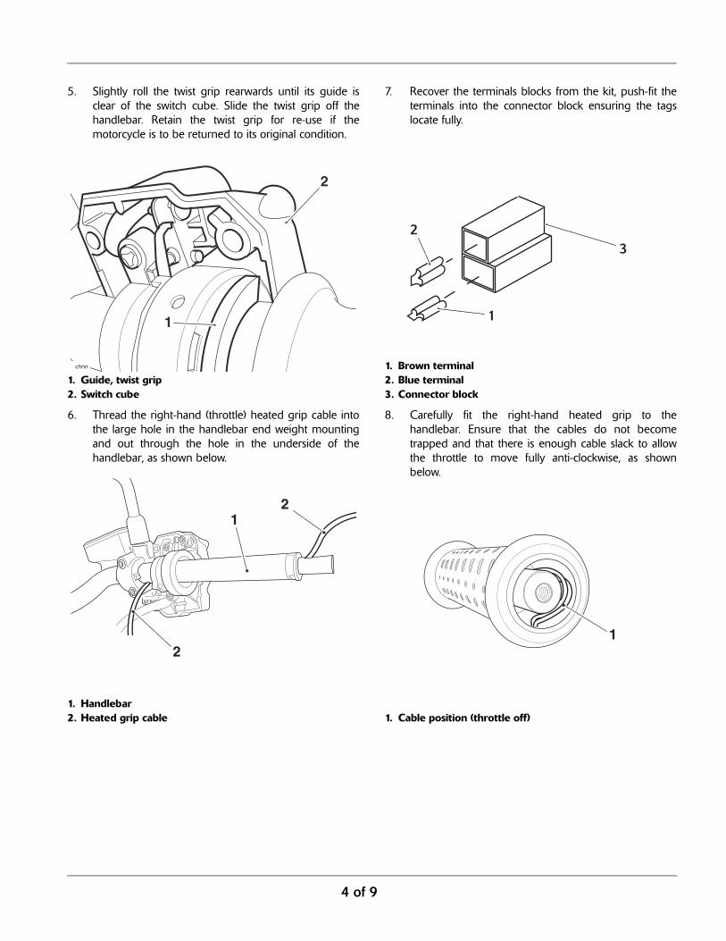
5. Slightly roll the twist grip rearwards until its guide isclear of the switch cube. Slide the twist grip off thehandlebar. Retain the twist grip for re-use if themotorcycle is to be returned to its original condition.
1. Guide, twist grip2. Switch cube
6. Thread the right-hand (throttle) heated grip cable intothe large hole in the handlebar end weight mountingand out through the hole in the underside of thehandlebar, as shown below.
1. Handlebar2. Heated grip cable
7. Recover the terminals blocks from the kit, push-fit theterminals into the connector block ensuring the tagslocate fully.
1. Brown terminal2. Blue terminal3. Connector block
8. Carefully fit the right-hand heated grip to thehandlebar. Ensure that the cables do not becometrapped and that there is enough cable slack to allowthe throttle to move fully anti-clockwise, as shownbelow.
1. Cable position (throttle off)
1
2
chnn
1
2
2
1
23
1
5 of 9
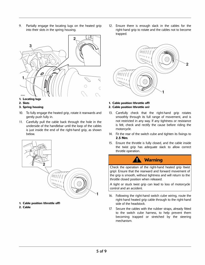
9. Partially engage the locating lugs on the heated gripinto their slots in the spring housing.
1. Locating lugs2. Slots3. Spring housing
10. To fully engage the heated grip, rotate it rearwards andgently push fully in.
11. Carefully pull the cable back through the hole in theunderside of the handlebar until the loop of the cablesis just inside the end of the right-hand grip, as shownbelow.
1. Cable position (throttle off)2. Cable
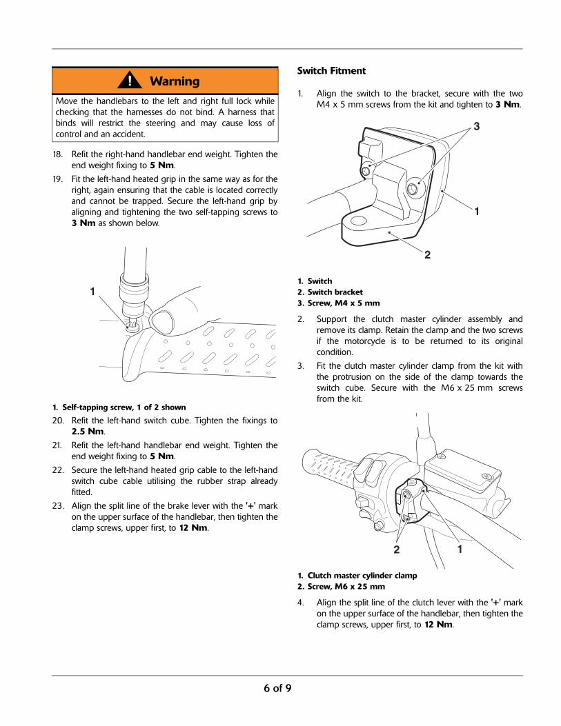
12. Ensure there is enough slack in the cables for theright-hand grip to rotate and the cables not to becometrapped.
1. Cable position (throttle off)2. Cable position (throttle on)
13. Carefully check that the right-hand grip rotatessmoothly through its full range of movement, and isnot restricted in any way. If any tightness or resistanceis felt, check and rectify the cause before riding themotorcycle.
14. Fit the rear of the switch cube and tighten its fixings to2.5 Nm.
15. Ensure the throttle is fully closed, and the cable insidethe twist grip has adequate slack to allow correctthrottle operation.
16. Following the right-hand switch cube wiring, route theright-hand heated grip cable through to the right-handside of the headstock.
17. Secure the cables with the rubber straps, already fittedto the switch cube harness, to help prevent thembecoming trapped or stretched by the steeringmechanism.
3
1
2
chnm
1
2Warning
Check the operation of the right-hand heated grip (twistgrip). Ensure that the rearward and forward movement ofthe grip is smooth, without tightness and will return to thethrottle closed position when released.
A tight or stuck twist grip can lead to loss of motorcyclecontrol and an accident.
1
2
6 of 9
18. Refit the right-hand handlebar end weight. Tighten theend weight fixing to 5 Nm.
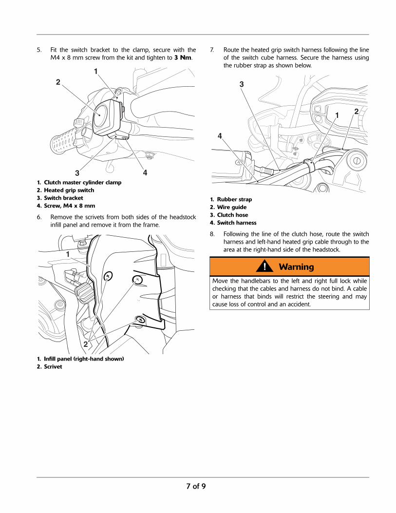
19. Fit the left-hand heated grip in the same way as for theright, again ensuring that the cable is located correctlyand cannot be trapped. Secure the left-hand grip byaligning and tightening the two self-tapping screws to3 Nm as shown below.
1. Self-tapping screw, 1 of 2 shown
20. Refit the left-hand switch cube. Tighten the fixings to2.5 Nm.
21. Refit the left-hand handlebar end weight. Tighten theend weight fixing to 5 Nm.
22. Secure the left-hand heated grip cable to the left-handswitch cube cable utilising the rubber strap alreadyfitted.
23. Align the split line of the brake lever with the '+' markon the upper surface of the handlebar, then tighten theclamp screws, upper first, to 12 Nm.
Switch Fitment
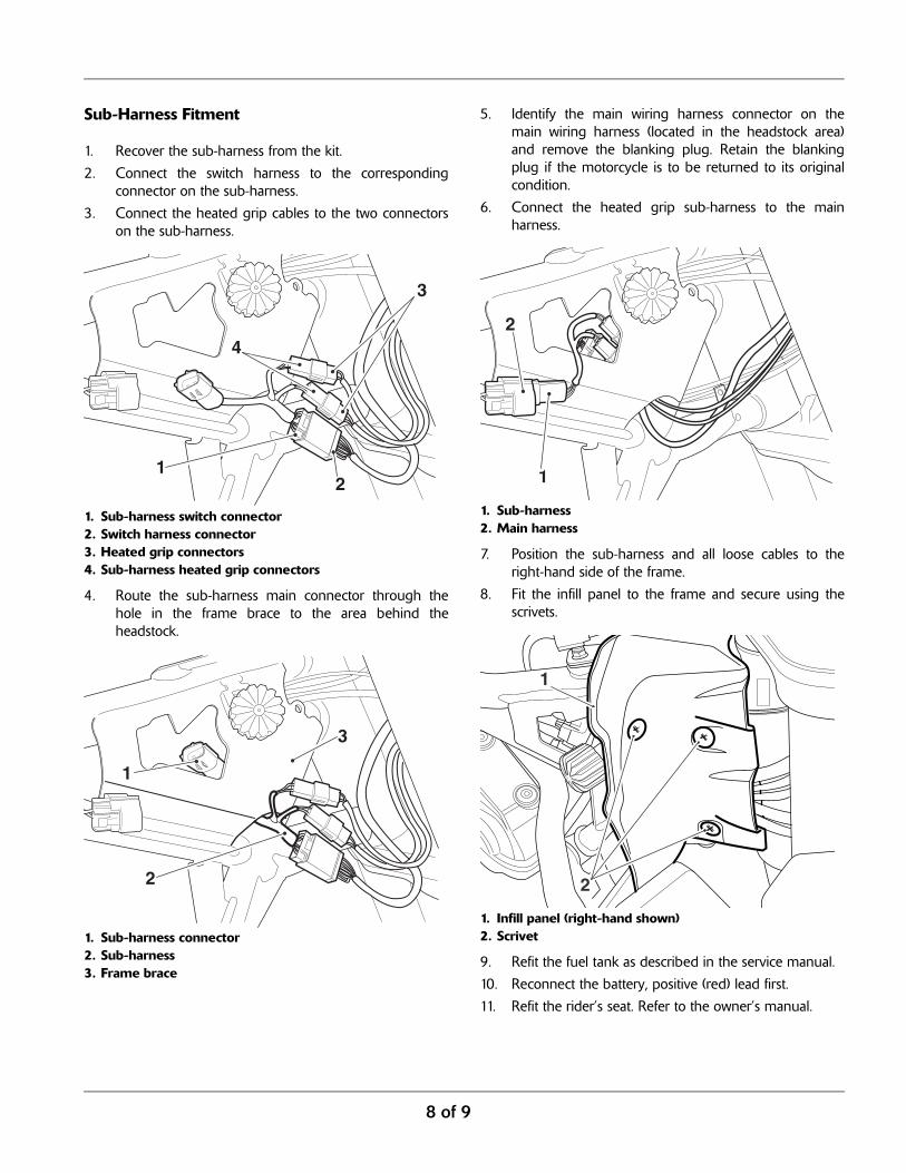
1. Align the switch to the bracket, secure with the twoM4 x 5 mm screws from the kit and tighten to 3 Nm.
1. Switch2. Switch bracket3. Screw, M4 x 5 mm
2. Support the clutch master cylinder assembly andremove its clamp. Retain the clamp and the two screwsif the motorcycle is to be returned to its originalcondition.
3. Fit the clutch master cylinder clamp from the kit withthe protrusion on the side of the clamp towards theswitch cube. Secure with the M6 x 25 mm screwsfrom the kit.
1. Clutch master cylinder clamp2. Screw, M6 x 25 mm
4. Align the split line of the clutch lever with the '+' markon the upper surface of the handlebar, then tighten theclamp screws, upper first, to 12 Nm.
WarningMove the handlebars to the left and right full lock whilechecking that the harnesses do not bind. A harness thatbinds will restrict the steering and may cause loss ofcontrol and an accident.
1
1
3
2
2 1
7 of 9
5. Fit the switch bracket to the clamp, secure with theM4 x 8 mm screw from the kit and tighten to 3 Nm.
1. Clutch master cylinder clamp2. Heated grip switch3. Switch bracket4. Screw, M4 x 8 mm
6. Remove the scrivets from both sides of the headstockinfill panel and remove it from the frame.
1. Infill panel (right-hand shown)2. Scrivet
7. Route the heated grip switch harness following the lineof the switch cube harness. Secure the harness usingthe rubber strap as shown below.
1. Rubber strap2. Wire guide3. Clutch hose4. Switch harness
8. Following the line of the clutch hose, route the switchharness and left-hand heated grip cable through to thearea at the right-hand side of the headstock.
43
21
1
2
WarningMove the handlebars to the left and right full lock whilechecking that the cables and harness do not bind. A cableor harness that binds will restrict the steering and maycause loss of control and an accident.
1
3
4
2
8 of 9
Sub-Harness Fitment
1. Recover the sub-harness from the kit.
2. Connect the switch harness to the correspondingconnector on the sub-harness.
3. Connect the heated grip cables to the two connectorson the sub-harness.
1. Sub-harness switch connector2. Switch harness connector3. Heated grip connectors4. Sub-harness heated grip connectors
4. Route the sub-harness main connector through thehole in the frame brace to the area behind theheadstock.
1. Sub-harness connector2. Sub-harness3. Frame brace
5. Identify the main wiring harness connector on themain wiring harness (located in the headstock area)and remove the blanking plug. Retain the blankingplug if the motorcycle is to be returned to its originalcondition.
6. Connect the heated grip sub-harness to the mainharness.
1. Sub-harness2. Main harness
7. Position the sub-harness and all loose cables to theright-hand side of the frame.
8. Fit the infill panel to the frame and secure using thescrivets.
1. Infill panel (right-hand shown)2. Scrivet
9. Refit the fuel tank as described in the service manual.
10. Reconnect the battery, positive (red) lead first.
11. Refit the rider’s seat. Refer to the owner’s manual.
12
3
4
1
2
3
1
2
1
2
9 of 9
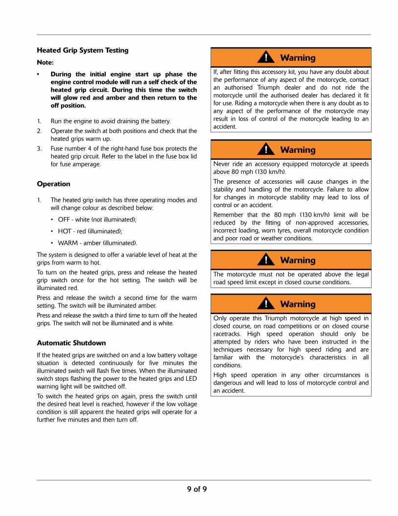
Heated Grip System Testing
Note:
• During the initial engine start up phase theengine control module will run a self check of theheated grip circuit. During this time the switchwill glow red and amber and then return to theoff position.
1. Run the engine to avoid draining the battery.
2. Operate the switch at both positions and check that theheated grips warm up.
3. Fuse number 4 of the right-hand fuse box protects theheated grip circuit. Refer to the label in the fuse box lidfor fuse amperage.
Operation
1. The heated grip switch has three operating modes andwill change colour as described below:
• OFF - white (not illuminated);
• HOT - red (illuminated);
• WARM - amber (illuminated).
The system is designed to offer a variable level of heat at thegrips from warm to hot.
To turn on the heated grips, press and release the heatedgrip switch once for the hot setting. The switch will beilluminated red.
Press and release the switch a second time for the warmsetting. The switch will be illuminated amber.
Press and release the switch a third time to turn off the heatedgrips. The switch will not be illuminated and is white.
Automatic Shutdown
If the heated grips are switched on and a low battery voltagesituation is detected continuously for five minutes theilluminated switch will flash five times. When the illuminatedswitch stops flashing the power to the heated grips and LEDwarning light will be switched off.
To switch the heated grips on again, press the switch untilthe desired heat level is reached, however if the low voltagecondition is still apparent the heated grips will operate for afurther five minutes and then turn off.
WarningIf, after fitting this accessory kit, you have any doubt aboutthe performance of any aspect of the motorcycle, contactan authorised Triumph dealer and do not ride themotorcycle until the authorised dealer has declared it fitfor use. Riding a motorcycle when there is any doubt as toany aspect of the performance of the motorcycle mayresult in loss of control of the motorcycle leading to anaccident.
WarningNever ride an accessory equipped motorcycle at speedsabove 80 mph (130 km/h).
The presence of accessories will cause changes in thestability and handling of the motorcycle. Failure to allowfor changes in motorcycle stability may lead to loss ofcontrol or an accident.
Remember that the 80 mph (130 km/h) limit will bereduced by the fitting of non-approved accessories,incorrect loading, worn tyres, overall motorcycle conditionand poor road or weather conditions.
WarningThe motorcycle must not be operated above the legalroad speed limit except in closed course conditions.
WarningOnly operate this Triumph motorcycle at high speed inclosed course, on road competitions or on closed courseracetracks. High speed operation should only beattempted by riders who have been instructed in thetechniques necessary for high speed riding and arefamiliar with the motorcycle’s characteristics in allconditions.
High speed operation in any other circumstances isdangerous and will lead to loss of motorcycle control andan accident.